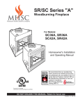
1
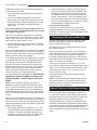
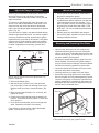
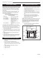
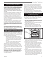
Winter Warm®
Small Insert
Homeowner’s
Installation
and Operating
Manual
For Use in North America
0888
WinterWarm
Small Insert
cover
4/01
Safety Notice: If this appliance is not properly installed, operated and maintained, a house fire may result.
To reduce the risk of fire, follow the installation instructions. Failure to
follow instructions may result in property damage, bodily injury or even
death. Contact local building officials about restrictions and installation
inspection requirements in your area.
Do Not Discard This Manual: Retain for Future Use
2000888 9/10 Rev. 21
WinterWarm® Small Insert
Introduction
Thank you for purchasing a Vermont Castings WinterWarm Small Insert, an efficient fireplace carefully engineered to
bring you the latest in wood combustion principles and modern foundry technology.
While it can be used to transform a traditional masonry fireplace into a powerful heater, it is also designed to be installed into a listed factory-built fireplace where no masonry fireplace and chimney exists.
Whichever installation you have chosen, you can count on years of comfortable heating and pleasurable fire-viewing if
you operate and maintain it according to the directions in this Owner’s Guide.
The WinterWarm Small Insert is listed by OMNI-Test Laboratories of Portland, Oregon, according to ANSI/UL 1482 for
the United States and ULC S628 for Canada. The WinterWarm Small Insert is listed to, and in compliance with, the
standards set forth by the Federal Environmental Protection Agency, 40 CFR Part 60.532(b), as stated on the permanent label attached to each appliance.
This manual describes the installation and operation of the WinterWarm Small Insert catalytic-equipped wood heater.
This heater meets the U.S. Environmental Protection Agency’s emission limits for wood heaters sold after July 1,
1990. Under specific test conditions this heater has been shown to deliver heat at a rate ranging from 8,700 to 31,000
BTU/hr.
For more complete details on WinterWarm Small Insert performance and specifications, please refer to Page 3.
The WinterWarm Small Insert is designed, tested and listed for burning wood. Do not burn other fuels.
Installation or service of the WinterWarm Small Insert should be performed only by a qualified installer, preferably NFI
or WETT (Canada) certified.
Please read the sections of this manual which apply to your installation before you install and use your WinterWarm
Small Insert.
Failure to follow these instructions may result in property damage, bodily injury or even death.
Save These Instructions for Future Reference
Table of Contents
Specifications.......................................................... 3
Installation............................................................... 4
Operation................................................................. 9
Maintenance.......................................................... 14
Catalytic Combustor Appendix.............................. 20
Replacement Parts................................................ 21
The WinterWarm Small Insert is designed,
tested and listed for burning wood. Do not
burn other fuels.
The WinterWarm Small Insert is not listed for
mobile home installations.
Failure to follow these instructions may
result in property damage, bodily injury or
even death.
Warning
Proposition 65 Warning: Fuels used in gas, woodburning or oil fired appliances, and the products of
combustion of such fuels, contain chemicals known
to the State of California to cause cancer, birth defects and other reproductive harm.
California Health & Safety Code Sec. 25249.6
This fireplace has not been tested with an
unvented gas log set. To reduce the risk of
fire or injury, do not install an unvented gas
log set into this fireplace.
2000888
WinterWarm® Small Insert
Specifications
WinterWarm Small Insert
EPA Emissions Rating........................g/hr, catalytic 2.1*
Range of heat output*................ 8,700 - 31,100 BTU/hr
Maximum heat output**...........................30,000 BTU/hr
Area heated***............................................. 1,000 sq. ft.
Size of wood splits..................................... 18” (460mm)
Fuel Capacity......................................... 30lbs. (13.5kg)
Loading...................................................................Front
Flue size...................................................... 6” (150mm)
Fireplace Insert weight.......................... 285lbs. (130kg)
Primary Air Control.........................Manual/thermostatic
Secondary Air Control.............................Self-regulating
Glass panel.......................... High-temperature ceramic
Flue exit position...................................................... Top
Blower rating................................110cfm. (115V, 60Hz)
*Under specific test conditions used during EPA emissions standard testing.
**This value can vary depending on how the unit is
operated, and the type and moisture content of the fuel
used. Figure shown is based on maximum fuel consumption obtained under laboratory conditions and on
average efficiencies.
***These values are based on operation in buildingcode conforming homes under typical winter climate
conditions in New England. If your home is of nonstandard construction (e.g. unusually well insulated, not insulated, built under ground, etc.) or if you live in a more
severe or more temperate climate, these figures amy
not apply. Since so many variables affect performance,
consult your Vermont Castings’ Authorized Dealer to
determine realistic expectations for your home.
1656O" (420mm)
656O"
(160mm)
2156M"
(535mm)
13" (330mm)
66M"
(165mm)
26" (660mm)
2156M" (535mm)
256" (650mm)
2156M"
(535mm)
0888
Fig. 1 WinterWarm Small Insert dimensions.
2000888
0888
WWsi
specifications
WinterWarm® Small Insert
Installation
Installing the WinterWarm Small Insert into an existing
masonry or factory-built fireplace is an effective way to
add an efficient heater to your home. The existing fireplace and chimney must meet certain requirements.
Requirements for Existing Fireplaces
The WinterWarm Small Insert is listed for installation
within a properly built masonry or heat circulating, masonry-type fireplace that is constructed in accordance
with the requirements of recognized building codes. A
heat-circulating masonry-type fireplace must conform
to building code standards for masonry fireplaces, and
must consist of a factory-built metal firebox with air
circulation pathways that are surrounded by masonry
materials. Air circulation pathways must not be blocked
by the insert or surround panels.
Requirements for Existing Chimneys
Chimney requirements differ for the U.S. and Canada.
Specifications for each are listed below. Connect the
insert to the chimney in accordance with local codes
and the requirements of the listing agency as specified
in this manual.
Chimney Height / U.S. and Canada
Chimney height should be no less than 15’ (4.5m)
above the hearth and no more than 35’ (10.5m).
The chimney should extend at least 3’ (914m) above
the highest point where it passes through a roof, and at
least 2’ (610mm) higher than any portion of a building
within 10’ (3m). (Fig. 2)
The fireplace and chimney must be clean and structurally sound. Have them inspected by a qualified professional chimney sweep, a mason, or your Vermont
Castings’ Authorized Dealer before the WinterWarm
Small Insert is installed. Any deterioration (cracks, loose
mortar or loose bricks) must be repaired.
Codes may permit removal of the damper in order to
make a positive connection for the vent between the
firebox and the chimney. However, the fireplace should
not be modified in any way without first checking with
your local building inspector or fire marshal. Provision
should be made to restore the fireplace to its original
condition if the insert is removed. Do not remove bricks
or mortar that may jeopardize the compliance of the
fireplace with local building codes.
The WinterWarm Small Insert is also listed for installation in tested and listed factory-built fireplaces. Listings
for factory-built fireplaces include meeting standards
for both the firebox and chimney. Review the owner’s
manual, and inspect the fireplace for metal tags or
labels which give information concerning installation of
inserts into the factory-built fireplace. Codes may permit
removal of the damper in order to install a chimney
liner. Codes may also permit removal of external trim
pieces which do not affect the operation of the unit, as
long as the pieces are stored on or within the fireplace
for re-assembly if the insert is removed. Air flow within
and around the fireplace shall not be altered (louvers
or cooling air inlet or outlet ports may not be blocked).
Louvered surrounds are permitted. Again, check with
local authorities before making any modifications.
0 To 10’
2’ Min.
3’
Min.
0 To 10’
2’ Min.
3’
Min.
Reference
Point
AC617
Fig. 2 The 2’-3’-10’ rule for chimneys.
Do not connect your WinterWarm small insert to a
AC617
chimney flue serving
another appliance.
RLTSKC8
2/11/98
U.S.
In the U.S. (ANSI/NFPA 211, 1988), when installed in a masonry fireplace:
• A connector must extend from the flue collar to the flue liner.
• The cross sectional area of the flue must be less •
•
than or equal to three times the area of the flue collar. If larger, the chimney must be re-lined.
Means must be provided to prevent room air passing to the chimney cavity.
Provision must be made for removal of the insert to clean the chimney flue.
2000888
WinterWarm® Small Insert
When the insert is installed in a factory-built fireplace:
• The factory-built chimney must meet type HT requirements of UL 103, ULC S629M or UL 127-
1988, or be re-lined from the insert to the chimney top.
General Considerations / U.S.
• While not required in most jurisdictions in the
•
•
U.S., MHSC strongly recommends a full stainless
steel chimney liner be installed for the insert to
the chimney top to increase overall performance
and reduce yearly maintenance.
A masonry chimney must be well-constructed
and must meet minimum code requirements.
The chimney flue should have a code-approved
liner made of masonry or pre-cast refractory
tiles, straight or flexible stainless steel pipe, or a
poured-in-place liner. An unlined chimney must
be relined professionally.
The chimney must have a nominal flue size of 6”
(152 mm) diameter, but no greater than 3 times
larger. A chimney larger than this must be relined.
Be aware that a chimney originally designed for fireplace use may perform differently when used to vent
an air-controlled appliance such as your WinterWarm
Small Insert - even if the flue is less than 3 times larger
than the flue collar. For example, a chimney on an
outside wall may not heat up enough to sustain an
adequate draft. Such a flue can often be improved if it
is relined to reduce its size and/or insulated to keep it
warmer.
• A positive flue connection must be made between the Insert and the first masonry tile or
prefabricated metal chimney section. A positive
flue connection consists of a plate that seals or
replaces the fireplace damper and a section of
chimney connector that passes through the plate
into the chimney. The chimney connector must be
a minimum equivalent to a 6” (152 mm) diameter
opening and must be 24 gauge or heavier stainless steel.
Chimney Connection systems are available from a
variety of manufacturers. Your Vermont Castings dealer
can recommend a system that will best meet the requirements of your particular installation.
Sealing Requirements / U.S.
• The chimney must be sealed off from room air,
either by a plate at the damper level or by sealing
the fireplace opening.
2000888
• Unused openings to the flue must be sealed with
masonry to the thickness of the chimney wall.
Openings sealed with pie plates or wallpaper are
a hazard. In the event of a chimney fire, flames
and smoke may be forced from the openings.
Canada
In Canada (CAN/CSA-B365-M91, Section 5), whether installed in a masonry or factory built fireplace:
• A full chimney liner meeting ULC S635, Class III
(stainless steel) must be installed from the insert
to the chimney top, and securely attached to
both. The damper may be removed to accommodate the liner.
• The opening of the fireplace around the insert
must be sealed to prevent room air passing to the
fireplace cavity.
• Existing air-circulation chambers in a fireplace
with a steel liner may not be blocked.
• Provision must be made for removal of the insert
to clean the chimney flue.
• A permanent metal warning label must be affixed
to the back of the fireplace stating the fireplace
may have been altered to accommodate the insert, and may be unsafe to use as a conventional
fireplace. (A Fireplace Modification Tag is included in the hardware bag inside the WinterWarm
Small Insert.)
Minimum Fireplace Dimensions
The WinterWarm Small Insert will fit most masonry and
factory-built fireplaces. To confirm that it will fit yours,
measure the lintel depth, plus the height, width, and
depth of your fireplace and hearth. Compare them to
the measurements in the accompanying chart. If you
choose to install a new hearth over an existing fireplace
hearth, be sure to take its thickness into consideration
when measuring both front and back height of the
fireplace.
The unit can be installed virtually flush with the fireplace
opening or it can extend up to 6³⁄₄” (172mm) onto the
hearth. Figure 3 gives minimum and maximum dimensions for fireplaces which will accommodate the WinterWarm Small Insert.
NOTE: The clearance between the WinterWarm Small
Insert and the mantel, top trim and side trim cannot be
reduced by installing shields.
Another requirement to consider is the clearance for
movable items such as tables, bookcases, rugs, furnishings, and your woodbox. All combustible materials of
this type should be a minimum of 48” (1220 mm) from
the front surface of the WinterWarm Small Insert. Be
sure that family members are aware of this requirement
as well, so they too will keep objects a safe distance
from the WinterWarm Small Insert.
WinterWarm® Small Insert
A
B
D,J
E
B
C
Measure
side trim
clearance
from here
A,I
Fireplace Minimums
A. Width at Face
26¹⁄₂” (673 mm)
B. Width at
9” depth
26¹⁄₂” (673 mm)
C. Depth1
14¹⁄₂” (370 mm)
D. Height at Face 21¹⁄₂” (540 mm)
E. Height at
15¹⁄₂” depth
21¹⁄₂” (540 mm) D,J
X
H
C
Fireplace Maximums
H. Lintel depth
9¹⁄₂” (240 mm)
I. Width2
44¹⁄₂” (1130 mm)
J. Height2
31” (770 mm)
FP1085
Fireplace Clearances
A. Mantel*
34” (865 mm)
B. Top Trim*
34” (865 mm)
C. Side Trim**
20¹⁄₈” (510 mm)
FP1085
* for more details on mantel
and top trim, see Note below.
WinterWarm
** Where side trim extends
more than 2” (50mm) from the fireplace
clearances
facing, the side clearance
3/01must be no less than 20⁵⁄₈” (525 mm).
E
FP1084
1. The minimum depth must be maintained from the floor of the
fireplace to a heightFP1084
of 21¹⁄₂” (540 mm)
2. Though the WinterWarm
Small Insert will fit into larger fireplaces,
winterwarm
the decorative optional MHSC Surround Panels will not completely
fireplace
minimum
dimensions
cover the fireplace opening
if these
dimensions
are exceeded. Custom made trim pieces
may
be
used.
3/01
Fig. 3 Use these measurements to confirm that the WinterWarm Small Insert will fit into your masonry fireplace.
Clearance Requirements
After confirming that your fireplace is the right size,
check the clearance to combustibles. First mark with
tape the exact center of your fireplace opening on the
hearth. Measure the side clearance from this point.
Measure the top trim and/or mantel clearances from the
finished hearth surface. Measure the front clearance (to
furnishings, etc.) from the fireplace face. (Fig. 4)
C
Measure the side clearance (C) from the exact center of your fireplace opening on the hearth (X). Measure the top trim (B) and/or
mantel clearances (A) from the finished hearth surface. Measure
the front clearance (to furnishings, etc.) from the fireplace face.
Fig. 4 Observe these clearances to combustible trim.
Hearth Requirements
In some fireplaces, the hearth in front of the fireplace
opening is brick, stone, slate, or some other non-combustible material that is in direct contact with concrete
poured over earth. These are the only hearths that are
considered noncombustible. In other fireplaces, the
brick or concrete hearth in front of the fireplace opening
is supported by heavy wooden framing. Because neither brick nor concrete has good insulating properties,
heat radiated by the fire will pass downward through
the hearth to the wooden framing. Such hearths are
considered combustible.
Unless the fireplace and hearth are constructed over a
completely non-combustible surface (such as unpainted
concrete over dirt), a floor protector must be used
in front of and to the sides of the door as protection
against spilled coals and embers. Floor protectors must
extend at least 8” (203 mm) from the side of the door
opening, making the protector 41” (1041 mm) wide. In
addition, the floor protector must extend from the front
door opening a minimum of 16” (406 mm) in the United
States and 18” (457 mm) in Canada. (Fig. 5)
2000888
WinterWarm® Small Insert
That is, when using brick for the hearth extension, the
brick must be a minimum of 2.6” (65mm) thick. Once
you know the K factor of a given material, you can use
this same formula to calculate its required thickness for
approved hearth protection.
The WinterWarm Small Insert has two leveling screws
at the front to accomodate hearth irregularities.
Optional Surround Packages
B
Custom-made surround panels may be made from any
noncombustible material.
B
A
MHSC offers both steel and cast iron Surround panel
kits, each in two sizes.
Enclosure Area
Steel Surround Trim Kits:
Shadow
Tray
C
United StatesCanada
A.16“ (410 mm) 18” (460 mm)
B. 8” (203 mm) 8” (203 mm)
C.41” (1040 mm) 41” (1040 mm)
6”, #2970..........................36¹⁄₂” x 27” (927 x 686 mm)
10”, #2971......................44¹⁄₂” x 31” (1130 x 787 mm)
Cast Iron Surround Trim Kits:
FP1095
FP1095
Fig. 5 Unless your fireplace
and hearth are constructed over
WWsi
Hearth over dirt), you must use a
a dirt floor (or unpainted concrete
djt requirements.
floor protector that satisfies4/3/01
the above
The approved construction of a floor protector calls
for a minimum of 24 gauge galvanized sheet metal or
equivalent such as 7/16” Durock® or Wonderboard® or
other listed floor protector. The floor protector may be
covered with a noncombustible decorative material if
desired.
Custom-made floor protectors may be used if they
offer the same protection as the approved floor protecNEW
thickness
K of
material (per
inch)
®
tor described
in new
the preceding
paragraph.
Durock
or
required =
of listed
x
®
Wonderboard
have
a
standard
K
value
of
0.84.
Custhickness
material
K of listed material (per inch)
tom-built floor protectors must have a K value equal to,
or less than 0.84, meaning that heat will transfer at the
same rate or more slowly than the tested standard.
To calculate the thickness required for an alternate
IWF291
material to result in a K value of 0.84, first determine
MBUF
6/19/96
the alternate material’s K factor. This information
should
be available from your local building supply yard. Then,
use the following formula to calculate the value:
(K factor
of alternate
material)
(0.84)
X (7/16" [11mm]) =
(Required thickness of
alternate material)
Let’s use brick as an example, since it is a commonly
used hearth material. Its K factor is 5.0.
(5.0)
(0.84)
2000888
7”, #2972.......................40” x 28¹⁄₂” (1016 x 724 mm)
10”, #2973........................45” x 31” (1143 x 787 mm)
Installing the WinterWarm Small Insert
The hardware bag included with your WinterWarm
contains the Draw-down assembly components that
provide a means to secure the chimney connector to
the Insert. Be sure you have the following items:
1, 1/4-20 x 6³⁄₄” Threaded Rod (A)
2, 1/4” Washers (B)
2, Hex Head Nuts (C)
1, 1/4-20 x 2” Hook (D)
1, 1” x 6” Steel Bar (E)
1, 1/4-20 Wing Nut (F)
1. Remove or Disable the Fireplace Damper.
A
C
B
D
E
F
If codes allow, remove the damper. Many dampers can
be removed simply by removing a cotter pin and/or
a
FP1096
WWsi
set screw.
pull down parts
If it is not permissible or possible to remove the4/01damper,
secure the damper in the fully open position.
~ NOTE: CANADIAN INSTALLATIONS ~
In accordance with CAN/CSA B365-M91, you must
permanently secure the Fireplace Modification Tag
to the rear of the fireplace cavity if you have modified the fireplace in any way to accommodate installation of a fireplace insert. This tag is in the hardware
bag included with your Insert.
2. Install the Chimney Connector System. Be sure
any chimney connector or adapter is properly installed and secured in place.
X (7/16" [11mm]) = 2.6" (65mm)
WinterWarm® Small Insert
3. Install the Chimney Connector Starter Pipe. (Not
supplied)
• Mark and drill two 5/16”, (8 mm) holes 1⁵⁄₈” (41
mm) from the lower edge of the pipe. Locate the
holes on an axis that will be perpendicular to the
fireplace opening when the pipe is installed. (Fig.
6)
16"
(35mm)
8.Join the Chimney Connector to the Flue Collar.
• Assemble the draw-down hook and bar (D,E,F).
• From inside the firebox, reach up through the flue
collar and engage the hook over the threaded
rod inside the starter pipe. Position the steel bar
behind the two tabs within the flue collar and then
turn the wing nut clockwise to draw the starter
pipe down. (Fig. 7)
9.Connect the Blower power cord to the power
supply.
This completes installation of your WinterWarm Small
Insert.
Seat the Starter
Pipe on the two
tabs inside the flue
collar
Fireplace
Front
Starter Pipe
Draw-down
Bar Assembly
FP1097
Fig. 8 Install the threaded rod inside the Starter Pipe (not a
supplied item, starter pipe is available from the Chimney Connector manufacturer).
• Install the threaded rod (A), into the starter pipe
using washers and hex nuts (B,C),on the outside
FP1097
of the pipe. Tighten
the nuts, but do not distort the
WWsi
pipe opening. (Fig. 6)
starter pipe
• Secure the starter
pipedjtto the chimney connector.
4/3/01
(Fig. 7)
4. Install the Floor Protector. Make sure the floor protector satisfies the requirements discussed on Page
6.
5. Install the Optional Outside Air Adapter. Follow
the instructions provided with the kit.
6. Install the Optional Surround Kit. Follow the instructions provided with the kit.
7. Slide the Firebox into Position. At least two people
will be needed to move the firebox. Position the
firebox so the flue collar lines up with the connector.
Use the leveling screws at the front of the Insert to
adjust the level. Route the power cord to the side
nearest the power supply and test the fans.
FP1098
Fig. 7 Attach starter pipe to flue collar.
FP1098
pipes to cabinet
4/01
2000888
WinterWarm® Small Insert
Operation
Your WinterWarm Insert’s
Controls and What They Do
Primary Air Control Lever
All WinterWarm Small Insert controls are conveniently
located on the front. (Fig. 8)
2:00 High
3:00 Medium
Three controls regulate the performance of your WinterWarm Small Insert:
4:00
4:30 Low
The primary air control supplies oxygen for the fire.
The damper directs air flow within the fireplace.
The variable-speed fan control, or rheostat, regulates
the warm air flow into the room.
Primary Air
Control Lever
Damper Control
Lever
FP1100
Fig. 9 Settings for the primary air control range from 2:00
(high burn rate) to 4:30 (low burn rate).
The Damper
The damper directs air flow within the fireplace. The
damper is operated by moving the lever located above
the door. It has two positions: Open, to start or revive
the fire; and closed, for normal operation. The damper
is open when the lever is to the far right, and closed
when to the far left. There are no intermediate settings
for damper position. (Fig. 12)
To open the damper, insert the fall-away handle into the
hole in the lever, lift up on the lever and move it to the
FP1100
far right.
WWsi
control
To close the damper, moveair
the
leversettings
to the left, continu4/03/01 djt
ing past the resistance to lock the damper in position.
Fan Speed Control
FP1099
Damper Open
Damper
Fig. 8 WinterWarm Small Insert controls.
Primary
Air Control
FP1099
WWsi
A single air control regulates the amount of heat the fire
controls
will produce and how long
it will burn.
4/01
The primary air control lever is located midway up
Secondary Air
Inlet
the left side panel. The lever regulates air for starting,
maintaining, and reviving the fire.
Generally, more air entering the stove makes the fire
burn hotter and faster, while less air prolongs the burn.
The WinterWarm Small Insert’s air supply is increased
when the control lever is moved counterclockwise, and
decreased when moved clockwise. It may be set anywhere between the two extremes, however, depending
on the amount of heat desired. (Fig. 9)
Damper Closed
Damper
FP1071a
WW si
damper open
4/03/01 djt
To complement the manual setting of the air control,
the WinterWarm Small Insert has an internal automatic
thermostat that ensures an even delivery of heat at the
manual setting you select.
Catalytic
Combustor
Secondary Air
Inlet
FP1071/2a
Fig. 10 When the damper is open, smoke is vented directly
to the chimney. When the damper is closed, smoke is chanFP1072a
nelled through the catalytic
combustor.
2000888
WWsi
damper closed
4/3/01
WinterWarm® Small Insert
The Fans
Two fans deliver a steady stream of warm air into the
room. Use the fall-away handle, (used to operate the
damper), to control fan settings. (Fig. 11)
The fan speed should be set at “low” when operating at
low to medium burn rates. The fan speed may be set
anywhere between “low” and “high” when operating at
high burn rates.
The control setting also depends on your particular
installation’s “draft,” or the force that moves air from the
stove up through the chimney. Draft is affected by such
things as the length, type, and location of the chimney,
local geography, nearby obstructions, and other factors.
Too much draft may cause excessive temperatures in
the WinterWarm Small Insert, and could even damage
the combustor. On the other hand, too little draft can
cause backpuffing into the room and/or the “plugging”
of the chimney or combustor.
How do you know if your draft is excessively high or
low? Symptoms of too much draft include an uncontrollable burn or glowing-red cast iron. A sign of inadequate
draft is smoke leaking into the room through the stove
or chimney connector joints, low heat, and dirty glass.
HIGH
OFF
LOW
FP1101
Fig. 11 Fan speed control settings.
Burn Only High-Quality
FP1101 Wood
fandesigned
switch position
The WinterWarm Small Insert is
to burn
4/01
natural wood only; do not burn fuels other than that for
which it was designed.
You’ll enjoy the best results when burning wood that
has been adequately air-dried. Avoid burning “green”
wood that has not been properly seasoned or cordwood
that is more than two years old.
The best hardwood fuels include oak, maple, beech,
ash, and hickory that has been split, stacked, and airdried outside under cover for at least one to two years.
In some newer homes that are well-insulated and
weather-tight, poor draft may result from insufficient air
in the house. In such instances, an open window near
the stove on the windward side of the house will provide
the fresh air needed.
Another option for getting more combustion air to the
stove is to duct air directly from the outside to the stove.
In fact, in some areas provisions for outside combustion
air are required in all new construction. To duct outside
air to your WinterWarm Small Insert, use Outside Air
Kit #3252 available from your Vermont Castings dealer.
Follow the installation instructions included with the kit.
When first using the stove, keep track of the settings
of the air controls. You will quickly find that a specific
setting will give you a fixed amount of heat. It may take
a week or two to determine the amount of heat and the
length of burn you should expect from various settings.
For areas that do not have a supply of hardwood, commonly burned softwoods include tamarack, yellow pine,
white pine, Eastern red cedar, fir, and redwood. These
too should be properly dried.
Most installations do not require a large amount of
combustion air, especially if adequate draft is available.
Do not for any reason attempt to increase the firing
of your heater by altering the air control adjustment
range outlined in these directions.
Your WinterWarm Small Insert will accept wood up to
18” (460mm). Longer wood pieces work better than
short ones.
Use the following primary air control lever and fan
speed control lever settings as a starting point to help
determine the best settings for your installation.
Wood should be stored under cover to maintain dryness. Even for short-term storage, however, keep wood
a safe distance from the heater and keep it out of the
areas around the heater used for re-fueling and ash
removal.
Use the Air Control Settings
that Work Best for You
No single air control setting will fit every situation. Each
installation will differ depending on the quality of the
fuel, the amount of heat desired, and how long you wish
the fire to burn.
10
WinterWarm Small Insert Control Settings
Primary AirAir Circulation
BurnControl
Rate
Setting
High
Medium
Low
FanControl
SpeedPosition
2:00
High
Horizontal
3:00 - 4:00
Low
Turn clockwise
4:30
Off Turn Counterclockwise
2000888
WinterWarm® Small Insert
How To Build and Sustain a Wood Fire
A WinterWarm Small Insert leaves the factory with the
combustor installed.
In the United States, it is against the law to operate this
wood heater in a manner inconsistent with operating
instructions in this manual, or if the catalytic combustor
is deactivated or removed.
High-Efficiency Wood Burning with
Catalytic Combustion
tor may stop working or the fire may go out if the fire
is allowed to die down immediately as a result of the
damper being closed. Once the combustor starts working, heat generated by burning the smoke will keep it
working.
To determine whether the combustor is operating, compare the amount of smoke leaving the chimney when
the damper is open and when it is closed. This procedure is described on Page 17.
Starting and Maintaining a Wood Fire
The components of the catalytic combustion system in
your WinterWarm Small Insert work together to produce
optimum conditions for secondary combustion.
Burn solid wood fuel only in the WinterWarm Small
Insert, and burn it directly on the grate. Do not
elevate the fuel. Do not burn coal or other fuels.
When the damper is closed, smoke is directed through
the catalytic element, which causes ignition of smoke
at temperatures of 450°-550°F (230°-290°C), half the
temperature normally required for unaided secondary
combustion.
Cast iron is a superior material for solid fuel stoves but
it must be treated with respect. It is extremely strong,
but can be broken with a sharp blow from a hammer
or from the thermal shock of rapid and extreme temperature changes. It is important to temper the cast iron
plates with an initial series of 3-4 break-in fires. The
plates expand and contract with changes in temperature. Minimize thermal stress by allowing the plates to
adjust gradually during the break-in fires by following
Steps 1-3 on the following page.
The catalytic element is a ceramic “honeycomb” coated
with the catalytic material. The element is located in
the secondary combustion chamber, molded from a
special high-temperature insulating refractory material. The design of the chamber provides the correct
environment necessary for secondary combustion of
the fuel (smoke).
Catalytic combustion is activated by closing the damper, thereby exposing the smoke to the combustor.
Closing the stove damper may also reduce the draft, so
to avoid putting out the fire or deactivating the combustor, close the damper only when a fire is well-established. When starting a fire, wait until the fire is well
established and there is an ember bed of at least 3-4”
(76 - 102mm) before closing the damper.
Never kindle a fire with colored paper or paper that
has colored ink or a glossy surface, and never burn
treated wood, garbage, solvents, or trash. All of these
may poison the catalyst and prevent it from operating
properly. Never burn cardboard or loose paper except
for kindling purposes. Never burn coal; doing so can
produce soot or large flakes of char or fly ash that can
coat the combustor and cause smoke to spill into the
room. Coal smoke also can poison the catalyst so that
it won’t operate properly.
In general, the fire must be sufficiently well-established
to ensure that catalytic activity is initiated. When first
starting a fire, a medium- to high- firing rate must be
maintained for at least twenty minutes. This ensures
the stove, catalyst, and fuel are all stabilized at the
proper operating temperatures.
Even though it is possible for the fire to get quite hot
within a few minutes after a fire is started, the combus-
2000888
Always be certain the damper is open when starting a
fire or when re-fueling. To open the damper, lift up on
the lever and move it to the right. (Fig.12)
Closed
Open
Damper Control Lever
FP1102
Fig. 12 Damper control.
WARNING: Operate your WinterWarm Small Insert
only with the door fully closed. If the door is left
FP1102
partially open, gas and
flame may be drawn out of
the fireplace opening,WWsi
creating risks of both fire and
smoke.
damper controls
4/01
11
WinterWarm® Small Insert
Follow these guidelines as you start and maintain the
fire, and remove the ashes.
1. Open the stove damper, and open the primary air
control fully.
2. Lay some crumpled newspapers on the bottom
grate. Place on the paper six or eight pieces of dry,
finely-split kindling. On the kindling lay two or three
larger sticks of split dry wood approximately 1-2”
(25-50 mm).
Do not use chemicals or fluids to start the fire. Do
not burn garbage or flammable fluids such as gasoline, naptha, or engine oil.
Also, never use gasoline-type lantern fuel, kerosene,
charcoal lighter fluid, or similar liquids to start or “freshen up” a fire in this heater. Keep all such liquids well
away from the heater while it is in use.
3. Light the newspaper and close the door. Gradually
build up the fire by adding a few 3-5” (76 -127 mm)
diameter splits.
If this is your initial break-in fire, let the fire burn brightly,
but not to excess. Control the fire’s intensity by adjusting the air control lever. After an hour or so stop adding
wood so that the fire dies out gradually.
For ongoing operation after the initial break-in, continue
to add a few sticks at a time of a progressively larger
size. Be sure to keep the fuel load behind the front
grate bar at all times. Continue until you have a live
ember bed at least 3-4” (76 - 102 mm) deep. This may
take an hour or longer, particularly when the WinterWarm Small Insert is vented to an exterior masonry
chimney or when you are just starting a fire.
You’ll soon find that the WinterWarm is HOT WHILE IN
OPERATION! KEEP CHILDREN, CLOTHING, AND
FURNITURE AWAY. CONTACT MAY CAUSE SKIN
BURNS.
NOTE: Some chimneys need to be “primed,” or
warmed up, before they will draw sufficiently to start
a fire. To correct this situation, roll up a couple pieces
of newspaper, place them on top of the kindling and
toward the back of the stove, light them, and close the
doors. This should heat the chimney enough to initiate
a draft.
Once the draft is established, open the front door and
light the rest of the fuel from the bottom. Do not light the
main bed of fuel until the chimney begins drawing, and
repeat the procedure as often as necessary if the initial
attempt is unsuccessful.
4. Once a good ember bed of at least 3-4” (76 - 102
mm) has formed, close the damper to activate the
combustor. To ensure continued operation of the
combustor, let the fire burn hot for an additional ten
to fifteen minutes after the damper is closed.
12
5. Close the primary air control to a medium-low setting. The fire volume will diminish immediately, but
the WinterWarm Small Insert will continue to heat
up. Maintain control of the fire using the primary air
control, and remember: reduce the setting for less
heat, increase the setting for more heat. Refer back
to the air control settings chart on Page 6 for recommended settings at different burn rates.
Do not over-fire this heater.
Overfiring may cause a house fire, or can result in
permanent damage to the stove and to the catalytic
combustor. If an exterior part of the WinterWarm Small
Insert glows, you are overfiring.
Reloading and Reviving a Wood Fire
Open the stove damper, set the air control on “High,”
and wait at least fifteen seconds for the draft to increase. Open the door slowly.
Check the ash level, and empty the ash pan if necessary. Replace the pan.
Add the fuel, smaller pieces first. If it is necessary to
use wood smaller than the 18” (460 mm) optimum size,
be sure to fill the firebox as completely as possible
by loading the wood pieces alternately on the left and
right. Split wood will fill the firebox more completely and
reduce the frequency of reloading.
If you have an ember bed of at least 3-4” (76 - 102
mm), leave the damper open and the thermostat set on
“high” for 10-15 minutes, then close the damper. If the
ember bed is less than 3-4” (76 - 102 mm), you may
have to let it burn longer.
Finally, adjust the air control and fan speed for your
desired heat level.
NOTE: If the charcoal bed is relatively thick and your
fuel is well-seasoned, it is possible to add fresh fuel
(smaller pieces first), close the door and damper, and
reset the air control immediately.
Special Tactics for Cold-Climate Heating
The WinterWarm Small Insert is capable of producing up to 30,000 Btu/hour and heating an area of up
to 1,000 sq. ft. However, many factors affect heating
performance and can influence the extent to which the
WinterWarm Small Insert can heat a given area.
A well-insulated home, located in a moderate climate
and with the WinterWarm Small Insert located centrally
in an open floor plan, will be easier to heat than a drafty
home in the far north in which a WinterWarm Small
Insert is installed on an exterior wall at the end of a long
house.
2000888
WinterWarm® Small Insert
In Fireplace Insert installations, over-sized chimneys
can produce less effective results than those that are
properly sized, and interior chimneys usually perform
better than those located outside the house.
Different results may be experienced even in the same
installation if you switch from burning good, dry wood to
wood that is partially rotted or inadequately seasoned.
To compensate for these factors in cold climates, it may
be necessary to operate the WinterWarm Small Insert
for longer periods of time than described above before
closing the damper, or to leave the air control set to a
higher level more of the time.
Remove and Store Ash Safely
Check the ash pan before reloading the stove, and
empty if necessary using the following procedure:
•
•
•
•
•
•
•
•
Turn off the fans.
Open the damper.
Open the load door.
Pull open the ash chamber door with the fallaway handle. (Fig. 13)
If the ash level is nearing the top, take the pan
outdoors and empty the ash into your ash container.
Ash may contain hot coals and must be treated
with extreme care.
Before replacing the ash pan, clear away any ash
that has spilled over the sides and back of the
pan.
Replace the ash pan and close the ash door and
front door.
Empty the ash pan regularly, typically every one to
three days. The frequency will vary depending on how
you operate your WinterWarm Small Insert; more
wood is consumed at higher heat output settings, and
ash will accumulate faster.
Ash should be removed frequently and placed outdoors
in a metal container with a
tight-fitting lid. The closed
container of ash should
be placed on a noncombustible floor or
on the ground, well
away from all combustible materials, pending final
disposal. If the ash is disposed of by burial in soil or
otherwise locally dispersed, it should be retained in
ST438
the closed container until all cinders
have thoroughly
cooled. Wood ash may be used asasha pail
garden fertilizer.
7/6/00 djt
CAUTION: Never use your household or shop vacuum
cleaner to remove ash from the fireplace; always remove and dispose of the ash properly.
Ash Pan
Ash Chamber Door
Load Door
FP1103
Fig. 13 Wear heavy stove gloves if it is necessary to handle
the ash when hot coals are present.
2000888
FP1103
Ash door
4/04/01 djt
13
WinterWarm® Small Insert
Maintenance
Keep Your WinterWarm Small Insert Looking New and Working Its Best
Care of the Cast Iron Surface
An occasional dusting with a dry rag will keep the
painted cast iron of your WinterWarm Small Insert looking new.
If the paint needs retouching, first allow the surface to
cool completely. Mask glass, trim parts and enamelled
areas. Wire-brush those areas needing to be painted.
Touch-up with high temperature stove paint available
from your local dealer. Apply the paint sparingly. Two
light coats are better than one heavy one.
Care of the Porcelain Enamel Surface
Use a soft brush as necessary. Do not use water or
other liquids on your WinterWarm Small Insert. Fingerprints usually can be buffed off porcelain enamel with a
dry, soft cloth. If marks remain, allow the WinterWarm
Small Insert to cool completely, then buff with a slightly
damp, soft cloth. Dry completely before starting a fire to
avoid streaking.
Never use abrasives or harsh chemical cleaners on the
porcelain enamel finish; the enamel may scratch and
expose the cast iron, which can then stain or rust. If
you must remove spills or stains from porcelain surfaces, make sure the fire is out and the WinterWarm Small
Insert has cooled completely before cleaning. Use a
kitchen appliance cleaner and/or polish specially formulated for enamel surfaces. Apply the cleaner sparingly
with a soft cloth, and buff away all traces.
Cleaning the Glass
The WinterWarm Small Insert glass system requires
a minimum amount of cleaning. Most carbon deposits
that accumulate will burn off during hot fires.
Ash residue that accumulates on the glass should be
removed periodically to prevent etching. To clean the
glass, use the following procedure.
• Be sure the glass is completely cool.
• Cleaning with water will work in most cases. Use
a glass cleaner especially made for this purpose
only if deposits are specially heavy. (If heavy
deposits are a frequent occurrence, however,
evaluate your operating techniques.) Do not use
abrasive cleaners.
• Rinse the glass thoroughly.
• Dry the glass completely.
14
NOTE: The WinterWarm Small Insert glass is
coated with a special material on one side that
helps reflect heat back into the fire chamber. Do
not attempt to remove this coating.
Adjust the Door Latch Periodically
The front door of the WinterWarm Small Insert should
close securely to prevent accidental opening and
should close tightly to prevent air from leaking into the
fire chamber. The door handle will be positioned vertically when the door is closed.
Over a period of time, the gasket around the door will
compress and the latch may need adjustment. To adjust the handle, follow this procedure:
1. Loosen the small lock nut with a 7/16” wrench. (Fig.
14)
2. Extend the striker screw one turn by turning it with a
1/8” Allen wrench.
3. Re-tighten the lock nut, while at the same time holding the striker screw with the Allen wrench to prevent
its turning.
Pawl
Small
Locking Nut
Striker Screw
Large
Locking
Nut
Set Screw
Handle Stub
ST531
Fig. 14 Turn the door latch striker screw in or out to tighten or
loosen the door latch.
ST531
Test the door seal. Close the door
on a dollar bill and
Pawl
attempt to pull it free. If the billDoor
is freed
with little resistance, the gasket isn’t snug11/00
enough at that spot.
Continue to make small adjustments until the setting is
right.
If additional adjusting of the latch does not enable the
door to seal sufficiently in one area, try “adjusting” the
gasket in that area. Pack more cement or a smaller
diameter gasket into the channel beneath the gasket so
the main gasket is raised and makes contact with the
door frame. If this procedure doesn’t solve the problem,
replace the gasket. Instructions for gasket replacement
are given later in this section.
2000888
WinterWarm® Small Insert
IMPORTANT NOTES
Adjust the Damper as Needed
• Do not operate the WinterWarm Small Insert if
Examine your WinterWarm Small Insert’s damper after
the first 50 hours of use and adjust it if necessary.
Thereafter, check the damper at least once a year and
adjust as needed.
the glass is damaged or broken.
• The glass used in your WinterWarm Small Insert
To inspect how well the damper seals, first make sure
the fire is out and the WinterWarm Small Insert is cool.
Open the front door, and close and lock the damper.
Inspect how the damper plate seals against the damper
frame. (Fig. 15)
There should be no gaps in the gasket and the damper
should be tight against the frame. If a section of gasket
is missing, replace the gasket. Instructions for gasket
replacement are given later in this section. If the gasket
appears to be in good condition, continue by pushing
gently on the damper. There should be some give but
no rattle. If adjustment is necessary, proceed as follows:
Damper Latch
•
Removing and Replacing Door Glass
Follow this procedure to replace glass.
• Open the door and loosen the four retaining clip
Latch
Retaining
Screw
•
Damper Control
Rod
FP1105
Fig. 15 With the mantel removed, the damper latch is exposed for adjustment.
1. Remove the Mantel piece.
2. With the Damper Control Lever in the open position (to the right), loosen the retaining screw on the
Damper Latch by turning it counterclockwise. (Fig.
FP1104
15
3. Move the latch approximately
WWsi1/16” to the left, and
tighten the screw.
damper adj
4. Examine the upright tab that holds the damper rod
4/01
in place. If the screw is
loose, tighten it. If the tab is
bent, replace it.
5. Close and lock the damper, and check for gap and
rattle. Repeat the procedure if necessary.
is coated with a special material on one side that
reflects heat back into the fire chamber. To replace new glass correctly, look along the edge of
the glass for a printed notice that reads, “THIS
SIDE OUT”. Be sure to install the glass with the
notice side out.
Replace glass only with MHSC high temperature ceramic glass, available from your Vermont
Castings’ Authorized Dealer.
•
•
•
screws that hold the glass to the door. Swing the
clips out of the way. Tilt the glass away from the door
frame and lift up. (Fig. 16) Wear gloves and use caution when handling broken glass.
Examine the gasket that seals the glass to the door
frame. Replace if necessary with gasket obtained
from your local Vermont Castings’ Authorized Dealer.
Directions for replacing gaskets are given below.
Check the channel at the bottom of the door frame,
and clear away debris if necessary.
Carefully place the new glass in the door frame.
Secure the clips, being careful not to over-tighten.
Be sure the glass is firmly seated against the gasket.
Close the door gently to confirm the clips have been
properly positioned. It is possible for the glass to be
damaged if the clips have been installed incorrectly
and the door is closed with force.
Gasket
If the problem is still not solved, replace the damper
gasket. Instructions are on Page 16.
Door
Gasket
Retainer
Clips
Fig. 16 Components fo the front door may be disassembled
to allow replacement of the glass, gaskets or both.
2000888
FP1105
WinterWarm
glass install
15
WinterWarm® Small Insert
How to Replace Gaskets
Replacing the Damper Gasket
Your WinterWarm Small Insert uses rope-type fiberglass gaskets to make a tight seal between some parts.
With use, particularly on those parts that move, gaskets
can become brittle and compressed and can begin
to lose their effectiveness. These will need periodic
replacement.
• Lift and remove the left and right burn plates.
• Two wedges hold the fireback in place. Using a
All of the gaskets used are made of fiberglass. The
three sizes of replaceable gasket are listed below,
along with their application.
•
Replaceable WinterWarm Small Insert
Fiberglass Gaskets
•
•
Gasket Size....................And The Parts It Seals
1/2” (1203564)................Door to the front - 5.6’
5/16” (1203591)..............Glass to the door - 5.2’
5/16” (1203588)..............Ash door to the front - 4’
.......................................Bypass damper - 2’
.......................................Damper housing - 2.5’
.......................................Fireback - 3’
3/16” (1203556)..............Thermostat cover to the left .......................................side - 1’
To change a gasket, wait until the fire is out and the
stove has cooled. Wear protective eyewear and a dust
mask. The procedure is the same for all gaskets.
1. Remove the existing fiberglass gasket by grasping
an end and pulling firmly.
2. Use a wire brush or the tip of a screwdriver to clean
the channel of any remaining cement or bits of gasket.
3. Apply a thin bead of stove cement to the newlycleaned groove.
4. Place a new gasket into the groove. Wait until you
have placed all but a couple inches from the end
before you trim the end to an exact fit.
Replacing the Insert’s Door Gaskets
• Remove the door by lifting it straight up from its
•
•
•
•
•
16
hinge pins.
Lay it face down on a padded surface.
Remove the glass. Follow the instructions for
removing and replacing glass which start on page
15.
Replace gaskets. Follow steps 1-4, above.
Replace the glass.
Replace the door.
•
hammer and a block of wood, tap upward on the
wedges and remove them.
Grasp the fireback by its vertical ribs and remove
it, together with the throat hood.
Disconnect the damper linkage from the damper
by removing the hex head bolt from the damper
tab.
Remove the two 1/4-20 screws holding the
damper housing to the back. The damper and
damper housing may now be removed.
Replace the damper gasket.
NOTE: Check the gaskets on the damper housing and
fireback while these components are out of the stove.
These gaskets seal non-moving parts and are much
less subject to wear than other gaskets, but can be
replaced if necessary.
• Reverse the procedure to replace the damper,
damper housing and fireback.
Damper Housing
and Bolts
Damper
Tab and Bolt
Linkage
Wedge
Wedge
Throat
Hood
Burn
Plate
Burn
Plate
Fireback
FP1106
Fig. 17 Remove the parts illustrated above to access the
damper.
FP1106
WinterWarm
Small Insert
damper access
4/4/01 djt
2000888
WinterWarm® Small Insert
Care of the Catalytic Combustor
Your wood heater contains a catalytic combustor which
should be inspected regularly and replaced periodically
to ensure proper operation. It is illegal in the United
States to operate this wood heater in a manner
inconsistent with operating instructions in this
manual, or if the catalytic element is deactivated or
removed.
Under normal operating conditions, the catalytic combustor should remain active for two to six years (depending on the amount of wood burned). However, it
is important to monitor the combustor to ensure it is
functioning properly, as well as to determine when it
needs to be replaced. A non-functioning combustor will
result in a loss of heating efficiency, and an increase in
creosote and emissions.
The combustor should be visually inspected “in place”
for fly ash accumulation and physical damage three
times per year. Actual removal of the combustor is not
recommended unless a more detailed inspection is warranted because of diminished performance as outlined
below.
The refractory package that houses the catalytic combustor should be inspected annually for a build-up of fly
ash and cleaned if necessary. This may be done during
examination of the catalytic combustor.
Burning “green” (insufficiently seasoned) wood will
result in poorer performance than burning properly
seasoned fuel. You may have to run your stove hotter
(more air) to achieve good performance if you are burning green or wet wood. Also, consider any changes in
your operating routine as well.
Once you have ruled out any other possible causes
for a decline in performance, you may proceed with an
inspection of the combustor.
Removal and Inspection of the Combustor
and Refractory Package
Before you begin, observe the basic safety precautions
for working with dusty materials: always wear protective eyewear, a recommended dust mask, and gloves.
1. Remove the andirons and burn plates.
2. Two cast iron wedges hold the fireback in place. Using a block of wood and a hammer, tap the wedges
upward. (Page 16, Fig. 17)
3. Grasp the fireback by its vertical ribs and remove it,
together with the throat hood.
4. Clean the left and right exhaust pockets of the
refractory package. Use a shop vacuum to avoid
damaging the fragile refractory material. (Fig. 18)
When To Suspect a Combustor Problem
The best way to evaluate the performance of your
WinterWarm Small Insert’s combustor is to observe the
amount of smoke leaving the chimney — both when the
combustor has achieved “light-off” and when it has not.
Follow this simple two-step procedure:
Refractory
Plug
Exhaust
Pockets
• With a fire going and the combustor properly
•
activated with the damper closed to route smoke
through it as described in the Operation Section,
go outside and observe the smoke leaving the
chimney.
Then, open the stove damper and once again
observe the smoke leaving the chimney.
Significantly more smoke should be observed after
the second step when the stove damper is open and
exhaust is not routed through the combustor. Be careful, however, not to confuse smoke with steam from wet
wood.
If this test indicates a problem, consider other possible
factors as well, such as the time of year or a change
in the quality of your fuel. In spring and fall, draft is
weaker than it is in colder winter weather, and fires can
burn sluggishly. Small, hot fires are a good solution
under these conditions.
2000888
FP1107
Fig. 18 The refractory package.
5. Inspect the gaskets that seal the fireback to the
damper frame and stove back. Replace if necessary.
6. Carefully remove the refractory plug.
7. Gently slide the catalytic element out of the refractory chamber. Check the element
and the bottom of
FP1107
the refractory chamber for a build-up of fly ash.
WWsi
8. If the honeycomb is clogged, take it outside for
refractory
package
cleaning. Blow gently through
the honeycomb.
A
sizeable quantity of ash may
be removed from the
4/01
element.
9. Inspect the element. Although small hairline cracks
will not affect performance, the element essentially
should be intact. If the element is broken in pieces
or has sections missing, it should be replaced. Call
your local Vermont Castings Authorized Dealer for a
replacement element, item #160-2521.
17
WinterWarm® Small Insert
If replacement of the refractory package is required,
proceed to #10.
10. Remove 1/4-20 x 1/2” hex head screw from the
damper tab holding the damper link to the damper and
let the link drop down.
11. Remove the two (2) 1/4-20 x 1Z\x” hex head screws
and washers holding the damper housing to the stove
back and drop the damper housing out of the stove.
The Chimney System
A Clean Chimney System is Safer
and Works Better
Although the catalytic combustion system in your WinterWarm Small Insert can reduce creosote formation
dramatically, it is not a substitute for regular inspection
and cleaning of the chimney and chimney connector.
12. Carefully slide the refractory package out of the
unit.
13. Install the new refractory package making sure to
pilot a small hole for the secondary probe in the proper
location at the back of the refractory package.
14. Reinstall the damper housing and damper link.
Catalytic Element
FP1108
Fig. 19 The refractory plug is removed to access the catalytic
element.
Watch for Better Results
Operate the stove in a typical manner for two weeks,
inspecting the chimney and the chimney connector frequently during thisFP1108
period. If creosote is not building up
as fast, it is likely the
performance change was caused
WinterWarm
by fly ash deposits on the catalytic element. However,
Small Insert
continue the inspections of the chimney system for a
Catalytic
element
few weeks to ensure
that proper
performance continues.
4/01
If you continue to find a significant creosote build-up
or if you continue to see excessive smoke from the
chimney, the catalytic element will need to be replaced.
Contact your nearest Vermont Castings Authorized
Dealer for information about a replacement element.
NOTE: Use only the replacement catalyst #160-2521
supplied by MHSC.
The refractory and the catalytic element are
extremely fragile and must be handled carefully.
18
Learn To Recognize —
And Avoid — Creosote
Your WinterWarm Small Insert has been designed to
minimize creosote build-up. Regular chimney inspection
and maintenance, however, must still be performed.
For safety, good stove performance, and to protect your
chimney and chimney connector, inspect your chimney
and chimney connector on a regular schedule. Clean
the system if necessary. Failure to keep the chimney
and connector system clean can result in a serious
chimney fire.
When wood is burned slowly, it produces tar, organic
vapors and moisture which combine to form creosote.
The creosote vapors condense in the relatively cool
chimney flue of a slow-burning fire. As a result, creosote residue accumulates on the flue lining. When
ignited, this creosote makes an extremely hot fire within
the flue system that can damage the chimney and
overheat adjacent combustible material. If a significant
layer of creosote has accumulated —1/8” (3mm) or
more — it should be removed to reduce the risk of a
chimney fire.
If you do experience a chimney fire, act promptly to:
• Close the damper and thermostat lever.
• Get everyone out of the house.
• Call the Fire Department from a nearby house.
You should inspect the system every two weeks during
the heating season as part of a regular maintenance
schedule. To inspect the chimney, let the WinterWarm
Small Insert cool completely. Then, using a strong light,
sight up through the flue collar into the chimney flue. If it
is not possible to inspect the flue system in this fashion, the firechamber must be removed to provide better
viewing access.
If it is necessary to remove the firechamber to inspect
or clean the chimney, this is how to do it:
• Let the WinterWarm Small Insert cool.
• Disconnect the fan power cord.
• You may wish to lighten the firebox by removing
•
the load door, andirons, grate and ash door.
Retract the two levelling screws until they bear no
weight.
2000888
WinterWarm® Small Insert
• Disconnect the flue liner or vent connector from
the flue collar of the stove.
• Slide the firechamber forward until you have access to the fireplace opening.
• Inspect the flue.
You can now inspect the smoke shelf area and the
chimney. Before replacing the WinterWarm Small Insert, this area should be inspected for signs of deterioration and cleaned thoroughly with a chimney brush.
Clean the chimney using a specially designed brush the
same size and shape as the flue liner. Flexible fiberglass rods are used to run the brush up and down the
liner, causing any deposits to fall to the bottom of the
chimney where they can be removed through the cleanout door.
The chimney connector should be cleaned by disconnecting the sections, taking them outside, and removing
any deposits with a stiff wire brush. Reinstall the connector sections after cleaning, being
sure to secure the individual sections with sheet metal
screws.
If your WinterWarm Small Insert is installed into a
factory-built fireplace, the chimney should be cleaned
from above using the appropriate size round brush and
enough rods to clean the entire length of the flue.
If you can’t do the chimney inspection yourself, contact your local Vermont Castings’ Authorized Dealer, or
engage a professional chimney sweep to perform the
inspection and cleaning of the chimney.
Fireplace System Maintenance Schedule
Fireplace:
Daily:
• Ash should be removed before the level reaches
•
Yearly Spring Cleaning:
• Remove ash from the firebox and replace with a
•
moisture-absorbing material (such as Kitty Litter)
to keep the interior of the fireplace dry.
Touch up painted surfaces with black paint.
Flex Connection:
Two Weeks:
• Inspect the chimney and flue connection. Clean
the system if necessary.
Yearly Spring Cleaning:
• Disassemble the flue connection and take it
•
Reverse the procedure to re-install the firechamber.
•
2000888
the top of the pan. Check each time you re-load,
or at least once a day.
Keep the area around the fireplace clear of any
combustible material.
outdoors for inspection and cleaning. Replace
weak sections of connector.
Inspect the chimney for signs of deterioration.
Repairs to a masonry chimney should be made
by a professional mason. Replace damaged
sections of prefabricated chimney. Your local
Vermont Castings’ dealer or a chimney sweep
can help determine when replacement is
necessary.
Thoroughly clean the chimney.
19
WinterWarm® Small Insert
Appendix: Catalytic Combustor
In any chemical reaction, including the combustion
process, there are certain conditions which must be
met before the reaction can take place. For example, a
reaction may require a certain temperature, or a certain
concentration of the reactants (the combustion gases
and oxygen), or a certain amount of time. Catalysts,
though not changed themselves during the reaction,
have the ability to act at a molecular level to change
these requirements. In the secondary combustion
chamber of the WinterWarm Small Insert, the catalyst
reduces the temperature at which secondary combustion can start from the 1000° - 1200°F (540° - 650°C)
range to the 500° - 600°F (260° - 315°C) range, increasing efficiency, and reducing creosote and emissions.
The catalytic reaction, though advantageous, does
have some limitations of its own. Primary among these
is the reactants (the gases) come into close physical
contact with the catalyst itself.
To ensure the necessary contact, the catalytic element in your WinterWarm Small Insert is composed
of a ceramic base in the shape of a honeycomb. On
each of the honeycomb’s many surfaces a coating of
the catalyst (usually a noble metal such as platinum or
palladium) is applied. The large surface area exposed
in this configuration ensures that the combustion gases
have the greatest opportunity to come in contact with
the catalyst.
Loss of catalytic activity will be apparent in several
ways. First you may notice an increase in fuel consumption. Second, there will be a visible increase in the
rate at which creosote builds up in your chimney connector system. You may also notice a heavy discharge
of smoke from the chimney. There are a number of
catalytic problems which can cause loss of activity:
Blockage
While the honeycomb pattern ensures good contact, it
also increases the resistance to flow of the combustion
gases, and, because of the many surfaces, provides
more places for creosote and fly ash to deposit. It is
important to follow the operating instructions in order
to minimize these deposits, and to periodically inspect
your catalyst for signs of blockage.
20
Masking and Poisoning
While the catalyst itself does not enter into the combustion process, it is possible for certain elements, such
as lead and sulfur, to attach to the active sites on the
surface of the honeycomb. Though the catalyst is still
there, it is covered, or masked, by the contaminant, and
cannot function. To avoid this situation, it is important
not to burn anything in your WinterWarm Small Insert
that is a source of these contaminants. Particularly
avoid painted or treated wood, coal, household trash,
colored papers, metal foils, or plastics. Chemical chimney cleaners may also contain harmful elements. The
safest approach is to burn only untreated, natural wood.
Flame Impingement
The catalytic element is not designed for exposure to
direct flame. If you continually over-fire your WinterWarm Small Insert the chemistry of the catalyst coating
may be altered, inhibiting the combustion process.
Thermal degradation of the ceramic base may also occur, causing the element to disintegrate. Stay within the
recommended guidelines of the Operation section.
Mechanical Damage
If the element is mishandled, damage may occur.
Always treat the element carefully. Remember the
catalyst is made of a ceramic material; treat it as you
would fine china. Hairline cracks will not affect the
performance of the catalyst, as long as the steel sleeve
holds the element in the proper position.
Peeling
Peeling of the surface coat may occur if the catalytic
element is frequently subjected to excessive temperatures. Follow the operating instructions carefully to
avoid this type of damage.
Every MHSC product is equipped with a Corning “LongLife”® “Honeycomb”®. If for any reason you must ship
your catalytic element, remember its fragile nature.
Place the element in a plastic bag, and package it with
a generous amount of shock absorbing material.
2000888
WinterWarm® Small Insert
23
26
47
24
9
30
55
41
6
43
54
42
10
56
61
13
11
14
15
57
29
44
45
31
28
7
17
14
12
32
16
27
18
17a
39
33
62
5
25
26
8
49
21
1
36
18a
35
4
52
58
19
37
38
24
59
22
20
40
48 53
60
50
51
34
3
Draw-down Kit
MHSC reserves the right to make changes in design, materials, specifications, prices and discontinue colors and products at any time, without
notice.
WinterWarm Small Insert
Model 2080
Item DescriptionPart Number
Item
14.
15.
16.
17.
17a.
18.
18a.
19.
20.
21.
22.
23.
24.
1.
2.
3.
4.
5.
6.
7.
8.
9.
10.
11.
12.
13.
Bottom Bottom Leg
Shadow Tray
Air Valve, Primary
Clip, Glass
Right Side
Left Side
Primary Air Cover
Back
Catalyst Block
Refractory Assembly
Throat Hood
Fiberglass Gasket
2000888
1301332
1301341
1301321
1601570
1601396
1301317
1301318
1301324
1301328
30001153
1602527
30001649
1203588
0888
WinterWarm
small insert
parts
6/01
DescriptionPart
Wedge
Catalyst Fireback
Front Frame II
Hinge, Upper
Hinge
Hinge, Lower
Ashpit Door Hinge
Ashpit Door
Gasket, Fiberglass
Gasket, Fiberglass
Door
Top
Air Reservoir
Number
1301340
1301346
1301367
1301325
1301366
1301326
1301336
1301335
1203588
1203564
See Chart Pg. 22
1301307
1301323
21
WinterWarm® Small Insert
WinterWarm Small Insert
5
Model 2080 (continued)
25.
26.
27.
28.
29.
30.
31.
32.
33.
34.
35.
36.
37.
38.
39.
40.
41.
42.
43.
44.
45.
46.
47.
48.
49.
50.
51.
52.
53.
54.
55.
56.
57.
58.
59.
60.
61.
62.
Item DescriptionPart Number
Coil & Shaft, Thermostat Assy.
5003733
Side Trim Panel
See Chart Pg. 22
Thermostat Cover
1301304
Gate Frame II
1301357
Left Burnplate
1301338
Right Burnplate
1301339
Grate
1301365
Andiron
1301333
Retainer
1301301
Ashpan
1402442
Fan Cover
1301331
Gasket, Fan Cover
1203588
Steel Handle Stub
30002723
Ashdoor Lockplate
1405797
Door Glass (19³⁄zn” x 11C⁄₈”)
1601571
Wood Handle
1600682
Wireform Handle
1600694
Insert, Lifter -Brushed Nickel
30002714
Mantel
See Chart Pg. 22
Damper Housing
1301348
Damper
1301347
Damper Handle
1301327
Damper Rod Connector
1601573
Damper Handle Adjusting Plate
1604507
Adjustable Airwash Plate
1405815
Hook Bolt
1201497
Threaded Rod 1/4-20 x 7¹⁄₂”
1204242
Steel Plate 1/4” x 1” x 8”
1405819
Wing Nut
1203110
Hex Nuts 1/4 20
1203210
Washer
1202470
Secondary Air Cover Plate
1601492
Secondary Air Probe Assy
1601489
Secondary Air Link
1601486
Secondary Air Flap
1601490
Gasket 5/16” Adhesive Backed
1203591
Door Handle Assy
30002717
Door Handle Pawl Assy
30002362
Access Plug
1602516
Shield, Primary Air
30002433
Shell Enamel Parts - WinterWarm Small Insert
Model 2080
Part NameClassic
Sand
Midnight
Door
1301322 1321322 1341322
Side Trim Panel 1301342 1321342 1341342
Mantel
1301320 1321320 1341320
22
2
3
1
4
6
ST724
7
8
MHSC reserves the right to make changes in design, materials, specifications, prices and discontinue colors and products at any time, without
notice.
Small WinterWarm Cabinet
Item DescriptionPart Number
1.
2.
3.
4.
5.
6.
7.
8.
Access Cover
ST724
Shell
Backside
WinterWarm
Outside
Airport Cover
Small Cabinet
Duct
8/8/02 djt
Duct Cover
Top Shell
Junction Box Cover Plate
Shell Bottom
Leveller Bolt
Fan
Rheostat Handle
Retainer Clips (1-Rheostat Handle
Fan Cable Assembly
Power Cord
Terminal Strip
Fan/Shroud Assembly
Rheostat Cable Assembly
Shaker Hole Plug
1405817
1405806
1408730
1405800
1405799
1405805
1405802
1405804
1201744
1601578
1601577
1601393
5003724
1601482
1204897
5003728
5003721
1600561
For parts and information about your insert, contact your
Vermont Castings authorized dealer. For the name of the
dealer nearest you, contact: MHSC
149 Cleveland Drive
Paris, KY 40361
800-668-5323
2000888
WinterWarm® Small Insert
Warranty
Limited 3 Year Warranty
MHSC warrants that this woodburning stove will be free of defects
in material and workmanship for a period of three years from the
date you receive it, except that the catalyst, thermostat assembly,
handles, glass door panels, cement, and gasketing shall be warranted as described below.
MHSC will repair or replace, at its option, any part found to be defective
upon inspection by a Vermont Castings, Authorized Dealer. The customer must return the defective part or the stove, with shipping prepaid,
to the Authorized Dealer or pay for any Authorized Dealer in-home
travel fees or service charges for in-home repair work. It is the dealer’s
option whether the repair work will be done in the customer’s home or
in the dealer’s shop. If, upon inspection, the damage is found to be the
fault of the manufacturer, repairs will be authorized at no charge to the
customer for parts and/or labor.
Any woodburning stove or part thereof that is repaired or replaced during the limited warranty period will be warranted under the terms of the
limited warranty for a period not to exceed the remaining term of the
original limited warranty or six (6) months, whichever is longer.
Limited 1 Year Warranty
The following parts of the woodburning stove are warranted to be free
of defects in material and workmanship for a period of one year from
the date you receive it: The thermostat assembly, handles, glass door
panels, cement, and gasketing. Any of these items found to be defective will be repaired or replaced at no charge, upon the return of the part
with postage prepaid to a Vermont Castings Authorized Dealer.
Any part repaired or replaced during the limited warranty period will
be warranted under the terms of the limited warranty for a period not
to exceed the remaining term of the original limited warranty or six (6)
months, whichever is longer.
Limited Catalyst Warranty
The catalyst will be warranted for a six year period as follows: If the
original catalyst or a replacement catalyst proves defective or ceases to
maintain 70% of its particulate emission reduction activity (as measured
by an approved testing procedure) within 24 months from the date the
stove is received, the catalyst itself will be replaced free.
From 25 - 72 months a pro-rated credit will be allowed against a replacement catalyst and the cost of labor necessary for its installation at
the time of replacement.
For stove purchases made after June 30, 1990, a third year
(25 - 36 months) of no charge replacement will be made when combustor failure is due to thermal degradation of the substrate (crumbling of
ceramic material). The customer must pay for any in-home travel fees,
service charges, or transportation costs for returning the stove to the
Authorized Dealer.
Amount of Time
Credit Towards
Since Purchase
Replacement Cost
0 - 24 months
100%
25 - 36 months
50%
37 - 48 months
30%
49 - 60 months
20%
61 - 72 months
10%
Any replacement catalyst will be warranted under the terms of the
catalyst warranty for the remaining term of the original warranty. The
purchaser must provide the following information in order to receive a
replacement catalyst under the terms of this limited warranty:
1. Name, address and telephone number.
2. Proof of original purchase date.
3. Date of failure of catalyst.
4. Any relevant information or circumstances regarding determination of failure.
5. In addition, the owner must return the failed catalyst.
2000888
Exclusions & Limitations
1. This product must be installed or serviced by a qualified installer,
preferably NFI or WETT (Canada) certified, as prescribed by the
local jurisdiction. It must be installed and operated at all times in accordance with the Installation and Operating instructions furnished
with the product any alterion, willful abuse, accident or misuse of
this product shall nullify this warranty.
2. This warranty is transferable; however, proof of original retail purchase is required.
3. This warranty does not cover misuse of the stove. Misuse includes
overfiring which will result if the stove is used in such a manner as
to cause one or more of the plates to glow red. Overfiring can be
identified later by warped plates and areas where the paint pigment
has burned off. Overfiring in enamel fireplaces is identified by bubbling, cracking, chipping and discoloration of the porcelain enamel
finish. MHSC offers no warranty on chipping of enamel surfaces.
Inspect your woodburning stove prior to accepting it for any damage
to the enamel.
4. This warranty does not cover misuse of the stove as described
in the Owner’s Guide, nor does it cover an stove which has been
modified unless authorized by a MHSC representative in writing.
This warranty does not cover damage to the stove caused by burning salt saturated wood, chemically treated wood, or any fuel not
recommended in the Owner’s Guide.
5. This warranty does not cover a stove repaired by someone other
than a Vermont Castings Authorized Dealer.
6. Damage to the unit while in transit is not covered by this warranty
but is subject to a claim against the common carrier. Contact
Vermont Castings Authorized Dealer from whom you purchased
your stove or MHSC if the purchase was direct. (Do not operate the
stove as this may negate the ability to process the claim with the
carrier.)
7. Claims are not valid where the installation does not conform to local
building and fire codes or, in their absence, to the recommendations
in our Owner’s Guide.
8. The salt air environment of coastal areas, or a high-humidity environment, can be corrosive to the porcelain enamel finish. These
conditions can cause rusting of the cast iron beneath the porcelain
enamel finish, which will cause the porcelain enamel finish to flake
off. This warranty does not cover damage caused by a salt air or
high-humidity environment.
9. MHSC shall have no obligation to enhance or update any unit once
manufactured.
IN NO EVENT SHALL MHSC BE LIABLE FOR INCIDENTAL AND CONSEQUENTIAL DAMAGES. ALL IMPLIED WARRANTIES, INCLUDING
THE IMPLIED WARRANTIES OF MERCHANTABILITY AND FITNESS,
ARE LIMITED TO THE DURATION OF THIS WRITTEN WARRANTY.
THIS WARRANTY SUPERCEDES ALL OTHER ORAL OR WRITTEN
WARRANTIES.
Some states do not allow the exclusion or limitations of incidential and
consequential damages or limitations on how long an implied warranty
lasts, so the above limitations may not apply to you. This warranty gives
you specific rights and you may have other rights which vary from state
to state.
How to Obtain Service
If a defect is noted within the warranty period, the customer should
contact a Vermont Castings Authorized Dealer or MHSC if the purchase
was direct with the following information:
1. Name, address, and telephone number of the purchaser.
2. Date of purchase.
3. Serial number from the label on the back.
4. Nature of the defect or damage.
5. Any relevant information or circumstances, e.g., installation,
mode of operation when defect was noted.
A warranty claim will then start in process. MHSC reserves the right to
withhold final approval of a warranty claim pending a visual inspection
of the defect by authorized representatives.
23
MHSC
149 Cleveland Drive • Paris, Kentucky 40361
www.mhsc.com