1
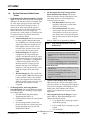
Easy Series Intrusion Alarm System
Release Notes for Version 3.0
January 2009
•
Trademarks
•
Microsoft®, ActiveX®, Windows® 2000, XP, NT®,
and Vista™ are either registered trademarks or
trademarks of Microsoft Corporation in the
United States and/or other countries.
•
InstallShield® is a registered trademark and
service mark of the Macrovision Corporation in
the United States and other countries.
•
Duracell® is a registered trademark of and
proprietary to Procter & Gamble, or other
respective owners that have granted P&G the
right and license to use such marks."
1.0
1.1
Control Panel Firmware
Version 3.0
GPRS and GSM Communication Support:
Control panel firmware 3.0 and later supports the
ITS-DX4020-G Integrated GPRS/GSM IP
Communicator. This device provides GPRS with
GSM backup communication.
•
24-Hour Trouble Point Type: The control panel
now supports a 24-Hour Trouble point type and
related event reports. Devices assigned to this
point type must be force-armed when faulted.
Faulting and restoring a 24-Hour point is
reported.
•
New Output Functions: Firmware version 2.8
supports two new output functions: Interior
Intrusion and Fire, and System On Unocccupied.
•
“Network“ Added as a New Reporting Format
Option: Firmware version 2.8 supports network
communication over an Ethernet network. Select
“Network“ as the reporting format for the desired
report route.
•
Missing wLSN Devices Can Cause a Tamper
Condition: You can configure wLSN devices to
create tamper conditions if they go missing.
•
Password Tamper Alarms: A passcode tamper
creates an alarm condition when the system is
armed. A passcode tamper alarm must be cleared
before you arm the system.
Event History Announcements: When the
installer listens to events in the history log, the
system now announces the event report status
after each event entry. After the event, a short
beep sounds, after which the system announces a
two-digit code that identifies the event status for
Routes 1 and 2. The first digit is the status for
Route 1, and the second digit is the status for
Route 2. Each digit ranges from 0 to 3:
•
0 = Local event or only logged in history log
(not announced) for this route
•
1 = Successful event transmission for this
route
•
2 = Unsuccessful event transmission for this
route
•
3 = The event is still pending for this route
For example: the cover is closed on a wLSN
siren, clearing the tamper condition. The tamper
restoral event is logged and sent to the CMS using
Route 1 only. When the installer listens to the
event history, this event is announced with a
date/time stamp, a single beep, followed by "10".
"1" indicates the event was successfully sent using
Route 1. "0" indicates that Route 2 was not
configured to send the report.
New Features
•
ICP-EZM2
•
Invalid Passcodes Threshold: Too many invalid
passwords create a tamper condition that is
recorded as a passcode tamper in the history log.
•
Programming Changes Now Recorded:
Changes that are recorded now include: installer
passcode changes; erase and discover command;
copy blue key data to the control panel; add
wireless devices; replace or delete devices; tranfer
data between control panel and hub; default
wireless devices; and switch wireless frequency.
•
Tamper Alarm When System is Disarmed
Options: If your system must generate a tamper
alarm when the system is accessed and the system
is diarmed, set an output to Interior Intrusion and
Fire. Enable a 3-min installer access window by
entering the Installer passocde. The system briefly
activates the output.
•
3-Min Installer Access Window: When the
installer passcode is used to access the installer
phone menu, a timer starts that allows access to
the installer phone menu for three minutes.
ICP-EZM2
•
Control Panel Alarms: Tamper alarms are
prevented when the control panel enclosure is
open. While disarmed, the installer passcode
silences alarms. If the control panel is armed, any
tamper condition creates an alarm.
•
System Inactivity Monitor: A System Inactivity
Monitor has been added for unarmed systems.
The feature includes an Inactivity Event report,
and Programming options.
1.2
Enhancements
•
New User Emergency Point Type: Use this
point type for supervisory alarm conditions. This
point type is always monitored and does not
depend on whether the control panel is armed or
disarmed.
•
Point Number Spoken When Assigned: When
a new point is discovered and a point number
assigned, the system announces “Point xx. “
•
Guard Code: User 22 can now support the
Guard Code feature. This feature allows a guard
to turn the system on or off—when special
conditions are met—using a token or telephone,
and it provides reports for system-off events.
•
•
1.3
Norway AC Fail Reports: For systems set to the
Norwegian country code (38), AC Fail reports are
delayed 60 minutes. AC Fail Restoral reports are
not delayed.
wLSN Hub Base Station Loss: The control panel
does not automatically recover from a wLSN hub
base station loss condition even though the
accompanying system trouble condition has been
cleared. To force the control panel to recover,
enter the Installer Telephone Menu and press
[1][6][4] to select the Transfer wireless data
(control panel-to-hub) option. Cycling system
power also forces the control panel to recover
from the condition.
•
Adding and then Deleting Wireless Devices in
RPS before Completing Discovery Process: If
you use RPS to add a wireless device, but then
delete the device before entering the telephone
menu to complete the discovery process (point
test), the control center announces the “wireless
devices not configured” message, which cannot be
cleared at the control center. To clear the
message, configure RPS to reset the control panel
when the online session ends, or cycle power to
the control panel.
•
Control Panel/wLSN Hub Firmware
Compability: Control panels using firmware
version 3.0 are not compatible with wLSN hubs
using firmware version 3.5 or earlier. For proper
control panel-to-hub communication, ensure the
wLSN hub is using firmware version 3.7 or later.
•
Point Tampers During Walk Test and Control
Center Operation: During Walk Test, if a point
is tampered and then restored, the control center
indicates a trouble condition by showing the
flashing circle. Control center announcements
might not occur as expected.
•
Unexpected Exit by Control Panel when in
Telephone Menu: The control panel does not
reset the 30-sec timer each time a key is pressed
on the control center when using the Operate
Outputs function. The control panel exits the
telephone menu after the initial 30-sec timer ends.
•
Force-armed 24-Hour Point Causes Alarm
when System is Disarmed: If a 24-hour point is
force-armed and then faulted, restored, and
faulted again, the point creates an alarm condition
immediately when the system is disarmed.
•
Swinger Bypass Limit and Restoral Events: If
the control panel is armed and a point exceeds
the swinger bypass limit, the control panel
immediately sends the restoral event to the central
station instead of waiting until it is disarmed.
No Tamper Alarm During Walk Test: In
firmware version 2.8, a tamper condition does not
create an alarm during a Walk Test.
Control Panel Known Issues
•
Force-armed 24-Hour Points and Restoral
Reports: If a 24-Hour point is faulted and then
force-armed, the system sends the restoral report
to the central station even though the condition
causing the fault has not been fixed.
•
Cannot Force-arm Tampered Fire Points: You
cannot force-arm tampered fire points (Fire
Instant or Fire Verified). To allow the system to
arm, you must fix the tamper condition.
•
•
Programming Item 159 (Start Arming with
Faulted Points: In Firmware 3.0, if Programming
Item 159 is disabled, all points that are faulted
before the control panel performs its fault check
must be force-armed.
ICP-EZM2 Release Notes
F01U088437-02
Page 2
© 2009 Bosch Security Systems, Inc.
ICP-EZM2
•
Cannot Clear Fire Trouble Condition: If a
trouble condition on a fire point occurs while the
system is arming and the condition cannot be
cleared by presenting a token or entering a
passcode, cycle power to the system to clear the
condition.
•
•
Cannot Clear Network Failure Condition: If a
network failure condition occurs and it cannot be
cleared, cycle power to the control panel.
1.4
•
•
Removing or Adding Devices While System
Power is Applied Causes Undesired
Configuration Changes: If you disconnect or
add a data bus device when the power is on, the
control panel configuration data might become
corrupted. For example, during the next power
cycle the control panel might report that wSLN
devices are lost. Remove all system power before
you add or remove any data bus devices.
Point Test Allows Testing of Some Devices
Only Once During Each Point Test Session: To
test a point again after the system announces
“Point xx was tested,” exit from and resume the
Point Test.
•
Fast Format Using Multiple Report
Destinations: If both report destinations in a
route are used (for example, Route 1 Primary and
Route 1 Backup), and you select Fast Format as
the format option for one destination, you must
select Fast Format for the other destination, too.
•
Status Announcements during One Button
System Test: To ensure that you hear the status
of all tests performed when you press the System
Test button, leave Expert Programming Item 139
(Verbose System Test Enabled) set to 1.
•
English SMS Text for “Point,” “Output,” and
“Key Fob”: “Point,” “Output,” and “Key Fob”
always appear in English in SMS text messages.
•
Fire Alarm Not Detected If Preceded by
Unrestored Tamper Condition: If a tamper
condition occurs on a fire point and it remains
unrestored when a fire alarm condition occurs on
the same fire point, the fire alarm condition is not
detected. This issue is valid only for a fire point
with its circuit style option set to 0 (dual 2.2 kΩ
alarm and tamper circuit).
Wall Tamper Condition Disables Control
Center: If a wall tamper condition occurs on a
control center with its wall tamper option enabled,
that control center is disabled and can no longer
access the system. Use a telephone or a keyswitch
to access or control the system.
Quick Start Guide Known Issues
Incorrect Key Sequence for Wireless
Configuration Menu: Section 3.0 Configure the System
incorrectly shows [6][1][2] as the key sequence to press
in order to enter the Wireless Configuration Menu.
The correct sequence is [1][6].
1.5
User Guide Known Issues
Incorrect LED Indications for Output Options in
Key Fob LED Status Table: Wireless key fob LED
status indications and output option descriptions are
listed below for Firmware Version 2.1:
•
Green on steady and slow amber flash: Either
or
was pressed to turn an output on or
off.
•
Red on steady and slow amber flash: Either
or
was pressed to turn an output on for
two seconds.
ICP-EZM2 Release Notes
© 2009 Bosch Security Systems, Inc.
Page 3
F01U088437-02
ICP-EZM2
1.6
•
System Reference Guide Known
Issues
No Description for Cross Zoning and Exit
Route/Non-Exit Route Points: The System
Reference Guide is missing a description of the
relationship between cross zoning and exit
route/non-exit route points.
No Description for Intrusion and Fire 2 Output
Type: The System Reference Guide is missing the
description for Intrusion and Fire 2 (Output Type
16). This output type goes into the alarm state
when any alarm occurs (Intrusion or Fire). It
remains in the alarm state until the system is
silenced, disarmed, or the bell cut-off time ends.
When a fire alarm occurs, this output type
provides only a steady output (no Temporal Code
3 or pulsed cadence). Fire alarms always take
priority over intrusion alarms.
•
•
•
On-board Outputs 1-3: The normal state
for these outputs is On, and the alarm
state is Off (reverse of Intrusion and Fire
output type). Select this output type for
these outputs to drive a siren or event
recorder where an alarm occurs when
power is removed from the system.
•
On-board Output 4: If Output 4 is
configured as an unsupervised open
collector, the Intrusion and Fire 2 output
type functions the same as for On-board
Outputs 1-3. If Output 4 is configured as
a supervised 8 Ω speaker driver, the
Intrusion and Fire 2 output type also
functions the same as for On-board
Outputs 1-3, but supervision only occurs
when the output is in the alarm state
(Off).
•
Wireless Outputs 5-8: The normal state
for these outputs is Off. The wireless siren
is silent, and the wireless relay module’s
relay is de-energized. In the alarm state
(On), the wireless siren is on steady, and
the wireless relay module’s relay is
energized.
No Description for Answering Machine
Override/Bypass: The System Reference Guide
is missing the steps for overriding or bypassing an
answering machine:
1. Set Phone Answer Ring Count (Expert
Programming Item 222) to 11.
2. Call the premises where the control panel
is installed.
3. If an answering machine answers the
phone call before the control panel, press
the [#] repeatedly until you enter the
Installer Phone Menu.
•
Exit Route Point: Exit Delay starts
regardless of the point’s current status
(normal or off-normal).
•
Non-exit Route Point: The point’s
current status must be normal at the start
of Exit Delay in order for the system to
arm. If the point is off-normal, the point
must be force-armed to allow the system
to arm.
Refer to Table 1 for programming conditions.
Table 1: Programming Exit Route or Non-Exit
Route Points
Exit Route Point
1. Set Expert Programming Item 159 (Start Arming with
Faulted Points) to 1 (Exit Delay starts with faulted
points).
2. Set the point’s cross zone value (Expert Programming
Item 9xx4) to 0 or 1.
0 = Cross zoning disabled, point is on the exit route.
1 = Cross zoning enabled, point is on the exit route.
Non-Exit Route Point
1. Set Expert Programming Item 159 to 0 (Force arm all
faulted points).
2. Set the point’s cross zone value to 2 or 3.
2 = Cross zoning disabled, point is not on the exit
route (must force arm).
3 = Cross zoning enabled, point is not on the exit
route.
•
Control Center Display State Tables: The
tables showing the control center display states
when the system is on (Occupied, Unoccupied, or
Custom) are incomplete. The flashing red circle
display state, which indicates active alarm
memory, also indicates that a system trouble
might exist.
•
Wireless Jam Detect Level Ranges: Control
panel values for Expert Programming Item 150
(Wireless Jam Detect Level) are:
•
1-7 to disable device reporting, but allow
wLSN Hub reporting.
•
8-15 to enable device reporting as a point
trouble.
• 12 is the default.
ICP-EZM2 Release Notes
F01U088437-02
Page 4
© 2009 Bosch Security Systems, Inc.
ICP-EZM2
3.0
2.0
wLSN 868 MHz
2.1
Known Issues
•
•
•
•
Tampered Hub Prevents Wireless Network
Configuration from being Saved: When
configuring the wireless network or programming
the wireless hub, do not tamper the hub (Address
50 Tamper). Doing so prevents the hub from
saving wireless configuration data.
No Dialer Delay for Key Fob Panic Alarm:
The control panel immediately sends a panic
alarm report to the central station when the
buttons are pressed simultaneously on
and
the wireless key fob.
Changing the Batteries in the Key Fob: Only
use 3 V lithium coin cell batteries (Duracell®
DL2032 or equivalent).
1. Remove the screws from the back of the key
fob, and remove the end cover (key ring
attached).
2. Remove the old batteries and replace with
new batteries.
Ensure that battery polarity is correct.
3. Replace the end cover and screws.
4. Test the key fob by pressing a button.
If the key fob fails, ensure the batteries are
properly installed, or re-enroll the key fob
into the system (User Maintenance Menu).
AC Failure Event History Message: If the
system announces an AC Failure message with a
point or output number, a wireless relay module
or siren lost power on its secondary power
terminals. If the system announces an AC Failure
message without a point or output number, the
control panel has an AC failure condition.
•
Unexpected Alarm Occurs When Pressing the
Button on the Wireless Key Fob: If there is
a faulted Interior point, and you press the
button on the wireless key fob five consecutive
times to arm the system, an unexpected alarm
might occur on the faulted Interior point.
•
Removing a Wireless Device from the System:
To properly remove a wireless device from the
system, select Option 3 (Delete a Device) from the
Wireless Configuration Menu. Changing the
wireless device’s function setting to 0 (Disabled)
does not delete the device from the system.
Data Bus Device Known Issues
•
DX4020 Firmware: To ensure proper operation
of the DX4020 with an Easy Series system,
upgrade the DX4020 firmware to version 2.23 or
later.
•
24-Hour Trouble Point Condition Cannot be
Cleared: If a trouble condition occurs on a 24Hour point connected to a DX2010, you must
remove and re-apply power to the control panel
to clear the condition. You cannot clear it from
the control center.
•
Disconnected DX2010 Alarm Cannot be
Cleared: After a missing points alarm occurs on a
DX2010, when the DX2010 is restored and the
system disarmed, the alarm does not clear. To
clear the alarm history, remove and re-apply
power to the control panel.
•
Fire Tamper Condition Does Not Clear on
DX2010 Fire Inputs When Tampered After an
Alarm Occurred on a Different Fire Input: To
clear tamper conditions for fire inputs after a
different fire input alarm initiates, cycle power to
the control panel.
•
Changing a Point Type and Exiting from the
Installer Menu Causes Missing DX2010: In the
rare event that this occurs, clear the missing
condition with the passcode or token.
•
Disconnected + or – Power From Any Data
Bus Device Causes Missing Bus Devices: All
bus devices might go missing when the + or –
power is disconnected from any data bus device.
Replacing the power restores all bus devices.
•
Shorted Data Bus Wires Cause Missing
Wireless Devices: If wireless devices are missing
as a result of shorted wires on the data bus, fix the
shorted wires, then remove and reapply all power
to the system to restore the missing wireless
devices.
ICP-EZM2 Release Notes
© 2009 Bosch Security Systems, Inc.
Page 5
F01U088437-02
ICP-EZM2
•
4.0
RPS 5.10 for Easy Series V2+
and V3+ Known Issues
4.1
Operational Issues
•
No Point Numbers Shown for 24-Hour Trouble
and Restoral Events: In RPS 5.10, the event
history for an Easy Series control panel account
does not show the associated point numbers for
24-Hour Trouble and 24-Hour Trouble Restoral
events.
•
Incorrect Status in History for Failed and
Pending Reports: If RPS retrieves history events
from an Easy Series control panel with firmware
version 3.0 installed, the history log shows an
event report status of Failed when the actual
status is Pending. The history log also shows an
event report status of Pending when the actual
status is Failed.
•
Cross Zone Time and Confirmed Alarm
Operation: If you select either of the Confirmed
Alarm options for Point Alarm Verification, RPS
allows a minimum entry of only 1800 sec (30 min)
for Cross Zone Timer. If you enter a value less
than 1800 sec, the control panel adjusts this entry
to 1800 sec, but does not update the cell display
accordingly in RPS. For example, if you set Cross
Zone Timer to 1500 sec, the control panel adjusts
this setting to 1800 sec, but RPS continues to
show 1500 sec as the entry. The maximum entry
of 3600 sec (60 min) is unaffected.
4.2
•
Help File Issues
Missing Modems in Modem Compatibility List
Topic (Easy Series V2+ and V3+ Help Files):
The following modems are missing from the
Modem Compatibility List topic:
Agere Systems AC’97 Modem
Keyfob Low Battery Acknowledge: This
parameter is not supported by RPS. Setting this
parameter has no effect on RPS or the control
panel.
•
Init String:
ATE0X1B0\G1\N1\Q0&K0S7=255S11=200S
10=255N0S37=5S8=5
•
Reset String: AT&F
Fire Verified Point Type Option Not
Supported by the wLSN Smoke Detector: The
wLSN smoke detector does not support the Fire
Verified point type option even though RPS
shows this as an available option.
Conexant CXT Soft Data Fax Modem with
SmartCP
•
Init String:
ATL1M1N0X0&C1&D2&Q0%C0\N0S7=255
S10=255
•
No User Number Shown for Key Fob Duress
Events: RPS does not show in the History List the
user number for Duress events initiated from a
wireless key fob. To identify the user number,
listen to the event in the control panel event
history, or view the event sent to the central
station receiver.
•
Reset String: AT&F
•
Cancel Events Show as Points instead of Users:
In the History List, Cancel events show as point
numbers instead of user numbers in the Details
column.
•
Incorrect External Power Messages for
Wireless Points: In rare cases, the External
Power field on the Diagnostics Points tab
incorrectly shows “Present” or “Missing” for the
wireless door/window contact, mini recessed
door/window contact, PIR detector, smoke
detector, and glass break detector. These messages
apply only to the wireless relay module and siren.
•
ICP-EZM2 Release Notes
F01U088437-02
Page 6
© 2009 Bosch Security Systems, Inc.
ICP-EZM2
•
Network Option Missing from Panel
Communication Topic (Easy Series V3+ only):
The Panel Communication topic does not include
information for the Network option.
•
Connect Via: Select Network for
network communication.
•
Panel IP Address: This field displays the
IP address as entered in the Panel Data
window. This field is read-only.
•
Panel Port Number: This field displays
the port number, to which the control
panel is connected, as entered in the
Panel Data window. This field is readonly.
•
•
Network Test: RPS conducts a network
test by sending a “ping” only as far as the
network interface module (NIM). If the
NIM hears the “ping,” it generates the
appropriate response and sends it back to
RPS. The Status field shows the result of
the network test.
•
Incorrect Screenshot Labels in UOM/UON
Tab Overview Topic: In the RPS Help, the
screenshot in the UOM/UON Tab Overview
topic shows incorrect labels. The incorrect labels
as shown in the screenshot are the Call In
Settings button, and the Expert Mode checkbox.
In RPS 5.10, the correct labels are the Panel Call
In Settings button, and the Expert Mode for
Easy Series V3+ checkbox.
•
Norwegian Easy Series Help File: The
Norwegian Easy Series help file contains incorrect
or missing descriptions for the following features:
•
Hours:Minutes from UTC (Panel DataNew Window or Panel Data-Edit
Window)
•
Expert Mode (Config→System and panel
account window)
For complete descriptions, refer to the English
Easy Series V3+ help file.
•
Norwegian RPS General Help File: The
Norwegian RPS general help file contains
incorrect operational descriptions for the
following features:
•
UOM/UON Tab (Config→System)
•
Hours:Minutes from UTC (Easy Series
V2+ and V3+ accounts only)
•
Supported Panel Types
(Config→System→Modem Tab)
For correct operational descriptions, refer to the
English RPS general help file.
•
Panel Test: RPS conducts a panel test by
sending a “ping” to the control panel at
the specified IP address. If the control
panel hears the “ping” from RPS, it
generates the appropriate response and
sends it back to RPS. This test confirms
that the physical link between the control
panel and RPS is correctly configured.
The Status field shows the result of the
panel test.
Help File Defaults: The defaults shown in the
help files for the Easy Series V2+ and V3+
control panels are for Country Code 58 (default
country code selection). If you change the country
code selection, RPS updates the defaults shown to
match the selected country code.
•
ICP-EZM2 Release Notes
© 2009 Bosch Security Systems, Inc.
Page 7
F01U088437-02
© 2009 Bosch Security Systems, Inc.
130 Perinton Parkway, Fairport, NY 14450-9199 USA
Customer Service: (800) 289-0096; Technical Support: (888) 886-6189
F01U088437-02
Release Notes
1/09
ICP-EZM2
Page 8 of 8