1
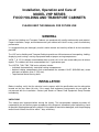
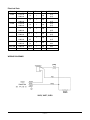
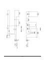
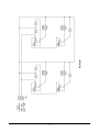
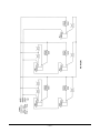
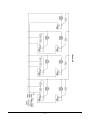
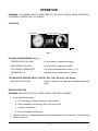
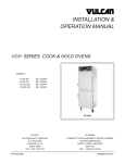
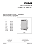
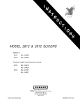
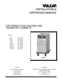
INSTALLATION &
OPERATION MANUAL
VHP SERIES FOOD HOLDING AND
TRANSPORT CABINETS
MODELS
VHP3
VHP7
VHP8
VHP15
VHP20
VHP7W
VHP72W
VHP73W
VHP74W
ML-126343
ML-126344
ML-126345
ML-126346
ML-126347
ML-126348
ML-126349
ML-126350
ML-126351
VHP7W
In U.S.A.:
In Canada:
VULCAN-HART COMPANY
P.O. BOX 696
LOUISVILLE, KY
40201-0696
TEL.: 502-778-2791
HOBART FOOD EQUIPMENT GROUP CANADA
190 RAILSIDE ROAD
NORTH YORK, ONTARIO
M3A 1B1
TEL.: 1-800-444-4764
F31080B (399)
PRINTED IN U.S.A.
TABLE OF CONTENTS
GENERAL............................................................................................................................................. 3
INSTALLATION .................................................................................................................................... 3
Unpacking ................................................................................................................................. 3
Location .................................................................................................................................... 4
Installation Codes and Standards ........................................................................................... 4
Electrical Connections ............................................................................................................. 4
Wiring Diagrams ....................................................................................................................... 5
OPERATION ...................................................................................................................................... 10
Controls .................................................................................................................................. 10
Before First Use ..................................................................................................................... 10
Operating Cabinet .................................................................................................................. 11
Cleaning .................................................................................................................................. 12
MAINTENANCE ................................................................................................................................. 12
Service and Parts Information ............................................................................................... 12
© VULCAN-HART COMPANY, 1998
—2—
Installation, Operation and Care of
MODEL VHP SERIES
FOOD HOLDING AND TRANSPORT CABINETS
PLEASE KEEP THIS MANUAL FOR FUTURE USE
GENERAL
Vulcan-Hart Holding and Transport Cabinets are produced with quality workmanship and material.
Proper installation, usage, and maintenance of your cabinet will result in many years of satisfactory
performance.
It is suggested that you thoroughly read this entire manual and carefully follow all of the instructions
provided.
The VHP series Holding and Transport Cabinets provide an efficient means of transporting, holding,
displaying, and serving a variety of prepared foods at proper serving temperatures.
VHP3, 7, 8, 15, 20 cabinets accommodate either a third, half, or full size steam table pans of various
depths. The cabinets will also accommodate the 1/1 gastronorm pan.
The VHP7W, 72W, 73W, 74W series cabinets include:
• Individual thermostatically controlled heating compartments.
• Ambient holding compartments that accommodate the standard 12x20" (305x508 mm) steam
table pans of depths up to 6" (152 mm).
• Top mounted heated serving wells.
INSTALLATION
Before installing, verify that the electrical service agrees with the specifications on the rating plate
located on the rear lower left side. If the supply and equipment requirements do not agree, do
not proceed with the installation. Contact your dealer or Hobart Food Equipment Group Canada
immediately.
UNPACKING
This cabinet was inspected before leaving the factory. The transportation company assumes full
responsibility for safe delivery upon acceptance of the shipment. Immediately after unpacking, check
for possible shipping damage to the cabinet. If the cabinet is found to be damaged, save the packaging
material and contact the carrier within 7 days of delivery.
—3—
Carefully unpack cabinet and place in a work-accessible area as near to its final installed position as
possible.
1. Remove cardboard carton and plastic bag covering the carton.
2. Carefully lift cabinet off carton bottom and place it on the floor.
3. Open cabinet door and remove any packaging materials used to hold tray slides in place.
LOCATION
For efficient cabinet operation, choose a location that will provide easy loading and unloading without
interfering with the final assembly of food orders.
The installation location must allow adequate clearances for servicing and proper operation.
INSTALLATION CODES AND STANDARDS
The cabinet must be installed in accordance with:
In the United States of America:
1. State and local codes.
2. National Electrical Code, ANSI/NFPA-70 (latest edition). Copies may be obtained from The
National Fire Protection Association, Batterymarch Park, Quincy, MA 02269.
In Canada:
1. Local codes.
2. Canadian Electrical Code, Part 1 CSA C22.1 (latest edition). Copies may be obtained from The
Canadian Standard Association, 178 Rexdale Blvd., Etobicoke, Ontario, Canada M9W 1R3.
ELECTRICAL CONNECTIONS
WARNING: ELECTRICAL AND GROUNDING CONNECTIONS MUST COMPLY WITH THE
APPLICABLE PORTIONS OF THE NATIONAL ELECTRICAL CODE AND/OR OTHER LOCAL
ELECTRICAL CODES.
WARNING: THIS APPLIANCE IS EQUIPPED WITH A FLEXIBLE ELECTRIC SUPPLY CORD
PROVIDED WITH A THREE-PRONG GROUNDING PLUG. THIS PLUG MUST BE CONNECTED
INTO A PROPERLY GROUNDED THREE-PRONG RECEPTACLE. IF THE RECEPTACLE IS NOT
THE PROPER GROUNDING TYPE, CONTACT AN ELECTRICIAN. DO NOT REMOVE THE
GROUNDING PRONG FROM THIS PLUG.
Refer to wiring diagrams in this manual (see pages 5-9).
All cabinets are equipped with an 8 ft. (2.4 m) cord and NEMA plug.
—4—
Electrical Data
Model
VHP3
VHP7
VHP8
VHP15
VHP20
VHP7W
VHP72W
VHP73W
VHP74W
Voltage
110/120
208/240
110/120
208/240
110/120
208/240
110/120
208/240
110/120
208/240
110/120
208/240
110/120
208/240
208/240
208/240
Amp
Phase
Hz
10
1
60
10
1
60
10
1
60
10
1
60
16.7
1
60
1
60
1
60
1
1
60
60
11.25
6.5
22.5
13
16.6
23.8
NEMA Plug
5-15
6-15
5-15
6-15
5-15
6-15
5-15
6-15
5-20
6-15
5-15
6-15
5-30
6-20
6-20
6-20
WIRING DIAGRAMS
VHP3, VHP7, VHP8
—5—
—6—
VHP7W
VHP15, VHP20
—7—
VHP72W
—8—
VHP73W
—9—
VHP74W
OPERATION
WARNING: THE CABINET AND ITS PARTS ARE HOT. BE VERY CAREFUL WHEN OPERATING,
CLEANING OR SERVICING THE CABINET.
CONTROLS
THERMOMETER
HEAT INDICATOR LIGHT
POWER INDICATOR LIGHT
FULL RANGE THERMOSTAT
PL-41226-1
Fig. 1
HOLDING COMPARTMENTS (Fig. 1)
POWER INDICATOR LIGHT
– Lit when power is supplied to cabinet.
HEAT INDICATOR LIGHT
– Lit when heat is supplied to cabinet.
FULL RANGE THERMOSTAT
– Turn to desired temperature setting (1-10).
THERMOMETER
– Indicates interior temperature of cabinet.
TOP MOUNTED SERVING WELLS (VHP7W, 72W, 73W, 74W Only - Not Shown)
RED INDICATOR LIGHT
– Light is lit when heat is supplied to Top Mounted Serving
Wells.
BEFORE FIRST USE
WARNING: UNPLUG ELECTRICAL POWER SUPPLY BEFORE CLEANING.
1. Clean cabinet thoroughly.
a. Use mild soap and water solution to clean cabinet.
b. Rinse thoroughly and wipe dry with a soft clean cloth.
c. Clean all accessories.
d. Rinse thoroughly and wipe dry.
2. Operate cabinet(s) in highest temperature setting for a period of 30-40 minutes. (See Operating
Cabinet, page 11.)
— 10 —
OPERATING CABINET
Holding Compartments (All Models)
1. Plug in electrical power supply.
• Power indicator light(s) is lit.
2. Turn thermostat knob(s) to desired setting.
• Heating elements begin heating.
• Heat indicator light(s) is lit.
3. Thermometer will indicate the interior temperature of the cabinet(s).
4. Once desired temperature is reached, heating elements will cycle on and off.
• Heat light(s) will cycle on and off with the heating elements.
5. Temperature in heated cabinet(s) will fluctuate as the heating elements cycle on and off.
6. Monitor the food product to ensure proper temperatures.
Top Mounted Serving Wells (VHP7W, 72W, 73W, 74W Only)
1. Turn thermostat knob(s) to 5.
• Heating elements begin heating.
• Red indicator light is lit.
2. Once desired temperature is reached, the heating elements will cycle on and off.
• Red indicator light will cycle on and off with the heating elements.
Cabinet Temperatures
The greater the thermostat setting number, the higher the cabinet(s) temperature. The lower the
thermostat setting number, the lower the cabinet(s) temperature.
Thermostat Setting
1
2
3
4
5
6
7
8
9
10
Approximate
Temperature
110°F
(43°C)
120°F
(49°C)
130°F
(54°C)
140°F
(60°C)
150°F
(66°C)
160°F
(71°C)
170°F
(77°C)
180°F
(82°C)
190°F
(88°C)
200°F
Shutdown
Unplug electrical power supply. Power indicator light will go off.
— 11 —
(93°C)
CLEANING
WARNING: UNPLUG ELECTRICAL POWER SUPPLY BEFORE CLEANING.
Clean cabinet interior with a mild soap and water whenever food spill occurs. Never use harsh
chemicals or abrasive pads to clean cabinet.
Daily
1. Allow cabinet to cool before cleaning.
2. Remove the tray slides and clean in a sink as you would any normal utensil.
3. Clean the interior of the cabinet(s) with a mild soap and water.
4. Rinse and dry with a soft dry cloth.
5. Replace tray slides in cabinet.
MAINTENANCE
WARNING: THE CABINET AND ITS PARTS ARE HOT. BE VERY CAREFUL WHEN OPERATING,
CLEANING OR SERVICING THE CABINET.
WARNING: UNPLUG ELECTRICAL POWER SUPPLY BEFORE SERVICING THE CABINET.
SERVICE AND PARTS INFORMATION
To obtain service and parts information concerning this cabinet, contact the Hobart Food Equipment
Group Office in your area or call 1-800-444-4764.
— 12 —