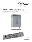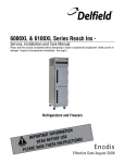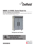
1
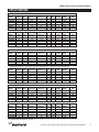
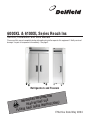
6000XL & 6100XL Series Reach Ins
Service, Installation and Care Manual
Please read this manual completely before attempting to install or operate this equipment! Notify carrier of
damage! Inspect all components immediately. See page 2.
Refrigerators and Freezers
TION
A
M
R
O
T INF
N
A
T
R
O
USE
IMP
E
R
O
F
E
ONS!
I
T
C
READ B
U
R
INST
E
S
E
H
T
AVE
S
E
S
A
E
PL
Effective Date May 2004
6000XL Series Service and Installation Manual
CONTENTS
RECEIVING & INSPECTING EQUIPMENT ................................. 2
SPECIFICATIONS........................................................................ 3
INSTALLATION .......................................................................... 4
OPERATION................................................................................ 5
MAINTENANCE .......................................................................6-7
PROGRAMMING GUIDE ............................................................ 8
WIRING DIAGRAMS .............................................................9-10
PARTS LISTING ..................................................................11-14
STANDARD LABOR GUIDELINES............................................ 15
STANDARD WARRANTIES .................................................16-17
AUTHORIZED PARTS DEPOTS.................................BACK PAGE
©2004 The Delfield Company. All rights reserved. Reproduction without
written permission is prohibited. “Delfield” is a registered trademark of The
Delfield Company.
SERIAL NUMBER INFORMATION
The serial number of all self-contained 6000XL Series
refrigerators and freezers is located above the door under the
shroud.
Always have the serial number of your unit available when
calling for parts or service. A complete list of authorized
Delfield parts depots is shown on the back.
This manual covers standard units only. If you have a custom
unit, consult the customer service department at the number
listed below.
RECEIVING AND INSPECTING THE EQUIPMENT
Even though most equipment is shipped crated, care should
be taken during unloading so the equipment is not damaged
while being moved into the building.
4.
1.
5.
2.
3.
2
Visually inspect the exterior of the package and skid or
container. Any damage should be noted and reported to
the delivering carrier immediately.
If damaged, open and inspect the contents with the
carrier.
In the event that the exterior is not damaged, yet upon
opening, there is concealed damage to the equipment
notify the carrier. Notification should be made verbally
6.
7.
as well as in written form.
Request an inspection by the shipping company of the
damaged equipment. This should be done within 10
days from receipt of the equipment.
Be certain to check the compressor compartment
housing and visually inspect the refrigeration package.
Be sure lines are secure and base is still intact.
Freight carriers can supply the necessary damage forms
upon request.
Retain all crating material until an inspection has been
made or waived.
For customer service, call (800) 733-8829, (800) 733-8821, Fax (989) 773-3210, www.delfield.com
6000XL Series Service and Installation Manual
SPECIFICATIONS
6000XL SOLID DOOR REFRIGERATORS
MODEL #
6025XL-S
6025XL-SH
6051XL-S
6051XL-SH
6076XL-S
6076XL-SH
VOLTAGE
115
115
115
115
115
115
AMPS
12
12
12
12
13
13
STORAGE
CAPACITY FT3
20.0
20.0
43.5
43.5
66.5
66.5
SHELF
CAPACITY FT2
15.1
15.1
33.2
33.2
48.3
48.3
H.P.
1/3
1/3
1/3
1/3
1/2
1/2
BTU
2885
2885
2981
2981
4148
4321
CHARGE
11
11
12.5
12.5
13
13
SHIP
WEIGHT
274 LBS
274 LBS
454 LBS
454 LBS
622 LBS
622 LBS
NEMA
PLUG
5-15P
5-15P
5-15P
5-15P
5-20P
5-20P
Remote units supplied with: Evaporator coil, solenoid valve, expansion valve, and temperature control. Condensing units to be sized and supplied by others.
REMOTE
MODEL #
6025XL-SR
6025XL-SHR
6051XL-SR
6051XL-SHR
6076XL-SR
6076XL-SHR
VOLTAGE
115
115
115
115
115
115
AMPS
5
5
6
6
7
7
STORAGE
CAPACITY FT3
20.0
20.0
43.5
43.5
66.5
66.5
SHELF
CAPACITY FT2
15.1
15.1
33.2
33.2
48.3
48.3
H.P.*
1/3
1/3
1/3
1/3
1/2
1/2
BTU
2885
2885
2981
2981
4148
4321
EVAP
TEMP
20°
20°
20°
20°
20°
20°
SHIP
WEIGHT
274 LBS
274 LBS
454 LBS
454 LBS
622 LBS
622 LBS
NEMA
PLUG
—
—
—
—
—
—
SHELF
CAPACITY FT2
15.1
15.1
33.2
33.2
48.3
48.3
H.P.
1/3
1/3
1/3
1/3
1/2
1/2
BTU
1994
1994
2453
2453
3057
3057
CHARGE
11
11
12.5
12.5
13
13
SHIP
WEIGHT
338 LBS
338 LBS
548 LBS
548 LBS
774 LBS
774 LBS
NEMA
PLUG
5-15P
5-15P
5-20P
5-20P
5-20P
5-20P
*Recommended; will vary with refrigerant used, contact factory.
6000XL GLASS DOOR REFRIGERATORS
MODEL #
6025XL-G
6025XL-GH
6051XL-G
6051XL-GH
6076XL-G
6076XL-GH
VOLTAGE
115
115
115
115
115
115
AMPS
12
12
14
14
15
15
STORAGE
CAPACITY FT3
20.0
20.0
43.5
43.5
66.5
66.5
Remote units supplied with: Evaporator coil, solenoid valve, expansion valve, and temperature control. Condensing units to be sized and supplied by others.
REMOTE
MODEL #
6025XL-GR
6025XL-GHR
6051XL-GR
6051XL-GHR
6076XL-GR
6076XL-GHR
VOLTAGE
115
115
115
115
115
115
AMPS
5
5
6
6
7
7
STORAGE
CAPACITY FT3
20.0
20.0
43.5
43.5
66.5
66.5
SHELF
CAPACITY FT2
15.1
15.1
33.2
33.2
48.3
48.3
H.P.*
1/3
1/3
1/3
1/3
1/2
1/2
BTU
1994
1994
2453
2453
3057
3057
EVAP
TEMP
20°
20°
20°
20°
20°
20°
SHIP
WEIGHT
338 LBS
338 LBS
548 LBS
548 LBS
774 LBS
774 LBS
NEMA
PLUG
—
—
—
—
—
—
SHELF
CAPACITY FT2
15.1
15.1
33.2
33.2
48.3
48.3
H.P.
1/2
1/2
3/4
3/4
3/4
3/4
BTU
1729
1729
3321
3321
3501
3501
CHARGE
18
18
18.5
18.5
17
17
SHIP
WEIGHT
274 LBS
274 LBS
454 LBS
454 LBS
622 LBS
622 LBS
NEMA
PLUG
5-15P
5-15P
5-20P
5-20P
5-20P
5-20P
*Recommended; will vary with refrigerant used, contact factory.
6000XL SOLID DOOR FREEZERS
MODEL #
6125XL-S
6125XL-SH
6151XL-S
6151XL-SH
6176XL-S
6176XL-SH
VOLTAGE
115
115
115
115
115
115
AMPS
12
12
15
15
16
16
STORAGE
CAPACITY FT3
20.0
20.0
43.5
43.5
66.5
66.5
Remote units supplied with: Evaporator coil, solenoid valve, expansion valve, and temperature control. Condensing units to be sized and supplied by others.
REMOTE
MODEL #
6125XL-SR
6125XL-SHR
6151XL-SR
6151XL-SHR
6176XL-SR
6176XL-SHR
VOLTAGE
115
115
115
115
115
115
AMPS
7
7
9
9
11
11
STORAGE
CAPACITY FT3
20.0
20.0
43.5
43.5
66.5
66.5
SHELF
CAPACITY FT2
15.1
15.1
33.2
33.2
48.3
48.3
H.P.*
1/2
1/2
3/4
3/4
3/4
3/4
BTU
1729
1729
3321
3321
3501
3501
EVAP
TEMP
-15°
-15°
-15°
-15°
-15°
-15°
SHIP
WEIGHT
274 LBS
274 LBS
454 LBS
454 LBS
622 LBS
622 LBS
NEMA
PLUG
—
—
—
—
—
—
*Recommended; will vary with refrigerant used, contact factory.
For customer service, call (800) 733-8829, (800) 733-8821, Fax (989) 773-3210, www.delfield.com
3
6000XL Series Service and Installation Manual
INSTALLATION
Location
Units represented in this manual are intended for indoor use
only. Be sure the location chosen has a floor strong enough
to support the total weight of the cabinet and contents. A fully
loaded 6000XL series can weigh as much as 1500 pounds.
Reinforce the floor as necessary to provide for maximum
loading. For the most efficient refrigeration, be sure to provide
good air circulation inside and out.
Inside cabinet: Do not pack refrigerator so full that air
cannot circulate. The refrigerated air is discharged at the top
rear of the unit. It is important to allow for proper air flow
from the top rear to the bottom of the unit. Obstructions to
this air flow can cause evaporator coil freeze ups and loss of
temperature or overflow of water from the evaporator drain
pan. The rear of the unit has molded ribs and the shelves
have a rear turn up on them to
prevent this. However, bags and
other items can still be located to
the far rear of the cabinet. There is
also a return air diffuser along the
top front of the cabinet interior, this
also requires proper air circulation.
Prevent obstruction by locating large
boxes and tall stacks of product
to the bottom of the cabinet. (See
Diagram at right)
Stabilizing
Some models are supplied on casters for your convenience,
ease of cleaning underneath and for mobility. It is very
important, however, that the cabinet be installed in a stable
condition with the front wheels locked while in use.
Should it become necessary to lay the unit on its side or back
for any reason, allow at least 24 hours before start-up so as to
allow compressor oil to flow back to the sump. Failure to meet
this requirement can cause compressor failure and unit damage.
Unit repairs will not be subject to standard
unit warranties due to improper installation
procedures.
Electrical connection
Refer to the amperage data on page 3, the serial tag, your
local code or the National Electrical Code to be sure the unit is
connected to the proper power source. A protected circuit of
the correct voltage and amperage must be run for connection
of the line cord, or permanent connection to the unit.
The thermostat must be turned to OFF and
the unit disconnected from the power source
whenever performing service, maintenance
functions or cleaning the refrigerated area.
Outside cabinet: Be sure that the
unit has access to ample air. Avoid
hot corners and locations near stoves and ovens.
It is recommended that the unit be installed no closer than 2”
from any wall with at least 12” of clear space above the unit.
Avoid exposing glass door units to direct sunlight. Direct
sunlight through the glass doors will make the ABS liner
fade and become brittle and will greatly reduce refrigeration
efficiency.
Leveling
A level cabinet looks better and will perform better because
the doors will line up with the frames properly, the cabinet will
not be subject to undue strain and the contents of the cabinet
will not move around on the shelves. Use a level to make sure
the unit is level from front to back and side to side. Units
supplied with legs will have adjustable bullet feet to make the
necessary adjustments. If the unit is supplied with casters, no
adjustments are available. Ensure the floor where the unit is to
be located is level.
4
For customer service, call (800) 733-8829, (800) 733-8821, Fax (989) 773-3210, www.delfield.com
6000XL Series Service and Installation Manual
OPERATION
Do not place hot pans on the blue ABS liner. Do
not throw items into the storage area. Failure
to heed these recommendations could result in
damage to the interior of the cabinet.
Temperature control instruction
Refrigerators: A thermostat located at the top of the
refrigerator, in the inset portion of the shroud assembly,
controls the temperature in the box. The factory setting for
the control is “4” and maintains about 38°F (3°C) in the box.
Set toward “1” for higher temperatures and toward “7” for
lower temperatures.
Freezers: A thermostat located at the top of the freezer,
in the inset portion of the shroud assembly, controls the
temperature in the box. The factory setting for the control
is “4” and maintains about -3°F (-18°C) in the box. Set
toward “1” for higher temperatures and toward “7” for lower
temperatures.
Refrigeration cycle
Refrigerators: During the refrigeration cycle the evaporator
fans will run continuously with the exception of door
openings. The door switch will activate the lights when
opened and turn power off to the evaporator fan motors.
1. The temperature control allows for the evaporator coil to
clear after each off cycle and before the compressor runs
again.
2. Anti-sweat heaters around each door opening operate
continually.
Freezers: During the refrigeration cycle the timer supplies
power to the temperature control (for power to the condensing
unit) and evaporator fan motors. The evaporator fans will run
at any time when the evaporator coil temperature is below
35°, they will also cycle off during door openings and during
a defrost period. The door switch will activate the lights when
opened and turn power off to the evaporator fan motors.
1. See Defrost Cycle
2. Anti-sweat heaters around each door opening operate
continually.
Defrost cycle - Freezers only
When defrost control goes into defrost, power to the
condensing unit and evaporator fans is interrupted and the
defrost heater is energized. The defrost heater warms the
evaporator coil thereby melting all frost accumulated during
the previous refrigeration cycle. Once all frost is eliminated,
the temperature of the coil continues to rise until it reaches
70°F (27°C). When this temperature is sensed by the defrost
limit control, the defrost control switches to refrigeration
mode.
If for any reason the timer remains in defrost for a period of
time greater than 40 minutes, a back-up defrost termination
is also provided which will terminate defrost at 80°F.
The defrost time can be changed in the field as follows: On
two and three door models push down and rotate pointer
on inside (2 hour) dial until it is opposite desired time
period (in minutes). On 1 door models, it can be changed
by adjusting the electric control switches 1 thru 4, “Defrost
Time” as shown on page 8 figure 1.
Freezer defrost control: All 6151XL-S & 6176XL-S freezers
are equipped with a Paragon 8145 defrost control for
automatic defrosting of the evaporator coil. All 6125XL-S
freezers are equipped with Air-O-Tronics time clock for
automatic defrosting of the evaporator coil. Air-O-Tronics
can not be adjusted to the time of day.
To set time of day (Two & three door models only): Grasp
the knob of the Paragon 8145 time clock dial in the center
of the inner (2 hour) dial and rotate it in a counter-clockwise
direction (see page 8 figure 2). This will revolve the outer
dial. Continue turning until the correct time of day on the
outer dial lines up with the time pointer. This operation
requires an initial start-up and any time thereafter when
there is an interruption of power to the freezer.
NOTE: There is no time adjustment for one
door models.
Operation (One door models): The electric defrost controller
is preset at the factory to provide a defrost cycle every 6
hours (4 defrosts per day). If it is necessary to change the
number of defrosts due to unusual operating conditions,
it can be accomplished by adjusting switches 1 thru 4 on
“Cycletime” dip switches.
Operation (Two & three door models): The Paragon 8145
timer is preset at the factory to provide four defrosts per day
at six hour intervals starting at 6:00 am. If it is necessary
to change the number of defrosts due to unusual operating
conditions it can be accomplished by placing the pins in
the outer dial at the appropriate time of the day that defrost
initiation is desired.
Even under the most severe operating conditions it should
not be necessary to set the back-up time greater than 60
minutes. Consult the factory if complete de-icing of the coil
is not accomplished within this time period.
For customer service, call (800) 733-8829, (800) 733-8821, Fax (989) 773-3210, www.delfield.com
5
6000XL Series Service and Installation Manual
MAINTENANCE
The thermostat must be turned to OFF and
the unit disconnected from the power source
whenever performing service, maintenance
functions or cleaning the refrigerated area.
Refrigerators and Freezers
The interior and exterior can be cleaned using soap and warm
water. If this isn’t sufficient, try ammonia and water or a
nonabrasive liquid cleaner. When cleaning the exterior, always
rub with the “grain” of the stainless steel to avoid marring the
finish.
Do not use an abrasive cleaner because it will scratch the
stainless steel and plastic and can damage the breaker strips
and gaskets.
Cleaning the Condenser Coil
The condenser coil requires regular cleaning, recommended
is every 90 days. In some instances though you may find
that there is a large amount of debris and dust or grease
accumulated prior to the 90 day time frame. In these cases the
condenser coil should be cleaned every 30 days.
If the build up on the coil consists of only light dust and debris
the condenser coil can be cleaned with a simple brush, heavier
dust build up may require a vacuum or even compressed air to
blow through the condenser coil.
If heavy grease is present there are de-greasing agents
available for refrigeration use and specifically for the condenser
coils. The condenser coil may require a spray with the degreasing agent and then blown through with compressed air.
Failure to maintain a clean condenser coil can initially cause
high temperatures and excessive run times, continuous
operation with dirty or clogged condenser coils can result in
compressor failures. Neglecting the condenser coil cleaning
procedures will void any warranties associated with the
compressor or cost to replace the compressor.
Never use a high pressure water wash for this
cleaning procedure as water can damage the
electrical components located near or at the
condenser coil.
Stainless Steel Care and Cleaning
To prevent discoloration of rust on stainless steel several
important steps need to be taken. First, we need to understand
the properties of stainless steel. Stainless steel contains 7080% iron which will rust. It also contains 12-30% chromium
which forms an invisible passive film over the steels surface
which acts as a shield against corrosion. As long as the
protective layer is intact, the metal is still stainless. If the film
is broken or contaminated, outside elements can begin to
breakdown the steel and begin to form rust of discoloration.
Proper cleaning of stainless steel requires soft cloths or plastic
scouring pads.
NEVER USE STEEL PADS, WIRE BRUSHES OR
SCRAPERS!
Cleaning solutions need to be alkaline based or non-chloride
cleaners. Any cleaner containing chlorides will damage
the protective film of the stainless steel. Chlorides are also
commonly found in hard water, salts, and household and
industrial cleaners. If cleaners containing chlorides are
used be sure to rinse repeatedly and dry thoroughly upon
completion.
Routine cleaning of stainless steel can be done with soap and
water. Extreme stains or grease should be cleaned with a
non-abrasive cleaner and plastic scrub pad. It is always good
to rub with the grain of the steel. There are also stainless steel
cleaners available which can restore and preserve the finish of
the steels protective layer.
Early signs of stainless steel breakdown can consist of small
pits and cracks. If this has begun, clean thoroughly and start
to apply stainless steel cleaners in attempt to restore the
passivity of the steel.
Never use an acid based cleaning solution!
Many food products have an acidic content
which can deteriorate the finish. Be sure to
clean the stainless steel surfaces of ALL food
products. Common items include, tomatoes,
peppers and other vegetables.
In order to maintain proper refrigeration performance, the
condenser fins must be cleaned of dust, dirt and grease
regularly. It is recommended that this be done at least every
three months. If conditions are such that the condenser is
totally blocked in three months, the frequency of cleaning
should be increased. Clean the condenser with a vacuum
cleaner or stiff brush. If extremely dirty, a commercially
available condenser cleaner may be required.
6
For customer service, call (800) 733-8829, (800) 733-8821, Fax (989) 773-3210, www.delfield.com
6000XL Series Service and Installation Manual
MAINTENANCE CONTINUED
If your freezer seems to vibrate excessively
when the compressor is running, loosen (but do
not remove) the bolts on the compressor. Semi
hermetic models should be loosened before
operating.
BASIC MAINTENANCE
Gasket Maintenance
Gaskets require regular cleaning to prevent mold and mildew
build up and also to keep the elasticity of the gasket. Gasket
cleaning can be done with the use of warm soapy water. Avoid
full strength cleaning products on gaskets as this can cause
them to become brittle and prevent proper seals. Also, never
use sharp tools or knives to scrape or clean the gasket which
could possibly tear the gasket and rip the bellows.
Gaskets can easily be replaced and do not require the use of
tools or authorized service persons. The gaskets are “Dart”
style and can be pulled out of the grove in the door and new
gaskets can be “pressed” back into place.
Doors/Hinges
Over time and with heavy use doors the hinges may become
loose. If it is noticed that the door is beginning to sag, it may
become necessary to tighten the screws that mount the hinge
brackets to the frame of the unit. If the doors are loose or
sagging this can cause the hinge to pull out of the frame which
may damage both the doors and the door hinges. In some
cases this can require qualified service agents or maintenance
personnel.
Drain Maintenance
Each unit has a drain located inside the unit which removes
the condensation from the evaporator coil and evaporates it
at an external condensate evaporator pan. Each drain can
become loose or disconnected from moving or bumping the
drain. If you notice excessive water accumulation on the
inside of the unit be sure the drain tube is connected from
the evaporator housing to the condensate evaporator drain
pan. If water is collected underneath the unit you may want
to check the condensate evaporator drain tube to be sure it
is still located inside the drain pan. The leveling of the unit is
important as the units are designed to drain properly when
on a level surface, if your floor is not level this can also cause
drain problems. Be sure all drain lines are free of obstructions,
typically food product is found blocking drain lines causing
water to back up and overflow the drain pans.
For customer service, call (800) 733-8829, (800) 733-8821, Fax (989) 773-3210, www.delfield.com
7
6000XL Series Service and Installation Manual
DEFROST TIMER PROGRAMMING GUIDE (ALL MODELS)
A (2) 4 position dip switch provides user control of defrost duration and
cycle time. The selection is as follows:
Programming Example
Defrost
Time
O 1 2 3 4
N
Defrost Time
off
off
off
off
off
on
on
on
off
off
off
off
on
off
off
off
off
on
off
off
off
on
on
on
on
on
min
void
5
10
15
20
25
30
35
40
45
50
55
60
Cycle Time
6 Hour Frequency
Typical Sequence of Operation
Period
40 Min
Frost Build Time
Compressor
Defrost terminated by
time or temperature
Defrost
6 Hour Cycle
Next cycle begins
(Figure 1)
Two and three section units only.
Paragon 8145
TIME POINTER
E
TIM
11
10
9
OUTER
(24 HR.) DIAL
NOO
N
1
8
K N OB
7
6
110
3
100
90
INSIDE
(2 HR.) DIAL
80
5
70
5
4
4
20
START PIN
40
K NO B
30
3
60
T
U
R
N
6
50
2
7
8
9
10 11
M
NIG ID
HT
1
hrs
void
2
4
6
8
10
12
14
16
18
20
22
24
10
off
off
off
off
on
off
off
off
on
on
on
on
on
2
off
off
off
off
off
on
on
on
off
off
off
off
on
2
Dip Switch
Setting
off
off
on
off
off
on
on
on
on
on
on
off
off
on
on
on
off
off
on
off
off
on
on
on
off
off
*Factory settings highlighted
O 1 2 3 4
N
40 Minute Duration
T
U
R
N
Dip Switch
Setting
off
off
on
off
off
on
on
on
on
on
on
off
off
on
on
on
off
off
on
off
off
on
on
on
off
off
*Factory settings highlighted
Cycle
Time
NOTE: The time
clock dial is
accessible by
removing the
larger plate of
the electrical box
located behind
the removable
louver.
BACK-UP
DEFROST
POINTER
Removing of the top panel or timer cover may
expose live electrical parts. Disconnect power
supply before servicing.
(Figure 1)
(Figure 2)
8
For customer service, call (800) 733-8829, (800) 733-8821, Fax (989) 773-3210, www.delfield.com
6000XL Series Service and Installation Manual
WIRING DIAGRAMS: REFRIGERATORS
All refrigerated models.
FRAME HEATER
(1 PER DOOR)
BLACK
WHITE
EVAPORATOR FAN(S)
BLUE
WHITE
JAMB SWITCH(ES)
(1 PER DOOR)
BLUE
RED
WHITE
BLACK
INTERIOR LIGHT
BLACK
RED
THERMOSTAT
BROWN
BLACK
SWITCH
COMP
WHITE
WHITE
BALLAST
BLACK
FLUORESCENT LAMP
L1 G N
For customer service, call (800) 733-8829, (800) 733-8821, Fax (989) 773-3210, www.delfield.com
9
6000XL Series Service and Installation Manual
WIRING DIAGRAMS: FREEZERS
MODELS: 6125XL
MODELS: 6151XL, 6176XL
1
O1
N
2
X
P2
K N OB
90
80
60
3
9
10
11
DEFROST
LINE NO
MID
NIGHT
TIMER RELEASE SOLENOID
3
PARAGON
8145-00B
OFF
OFF
ON
ON
WHITE
BROWN
PURPLE
BLACK
YELLOW
O
N
1 2 3 4
O
N
1 2 3 4
WHITE
BLACK
PURPLE
YELLOW
DEFROST LIMIIT
FAN DELAY
BROWN
WHITE
THERMOSTAT
BLUE
EVAPORATOR FANS
BLUE
WHITE
BLUE
JAMB SWITCH
(1 PER DOOR)
BLACK
INTERIOR LIGHT
BLACK
RED
WHITE
RED
BROWN
COMP
WHITE
DEFROST HEATER
YELLOW
WHITE
FRAME HEATER
BLACK
WHITE
L1
G
N
115V-1PH-60HZ POWER SUPPLY
( 2 & 3 DOOR FREEZER )
CORD & PLUG PROVIDED AS STANDARD
JAMBSWITCH SHOWN WITH DOORS CLOSED
10
For customer service, call (800) 733-8829, (800) 733-8821, Fax (989) 773-3210, www.delfield.com
ON
OFF
OFF
OFF
PURPLE
WHITE
PURPLE
BROWN
YELLOW
N
WHITE
4 X
1 2
BLACK
2
1
T
COMP
LINE NO
BROWN
6
70
50
8
4
AIR-O-TRONICS
MC1DD1062JN
40
K NOB
7
30
5
6
20
RN
P1
N
YELLOW
7
RN
10
5
TU
CR
P3
DEFROST
ON LED
2
TU
110
4
8
9
3
0
10
BLACK
DEFROST
234
NOON
11
O1
N
TI
M
E
DEFROST
INITIATE
10
CYCLE
TIME
234
2 & 3 DOOR
6000XL Series Service and Installation Manual
REPLACEMENT PARTS
6025XL-S
DESCRIPTION
Door gasket
Evap fan motor
Evap fan blade
Cond. fan motor
Cord & plug
Hinge cartridge
Spring hinge
Hinge brackets:
Top right
Bottom right
Casters:
With brake
Without brake
Legs
Door lock
Temp control
Thermometer
Expansion valve
Evap. coil
Condenser coil
Shelves
Shelf clip
Rocker switch
6051XL-S
DESCRIPTION
Door gasket
Evap fan motor
Cord & plug
Hinge cartridge
Spring hinge
Hinge brackets:
Top right or left
Bottom right
Bottom left
Casters:
With brake
Without brake
Legs
Door lock
Temp control
Thermometer
Expansion valve
Evap. coil
Condenser coil
Shelves LH
Shelves RH
Rocker switch
6076XL-S
DESCRIPTION
Door gasket
Evap fan motor
Cord & plug
Hinge cartridge
Spring hinge
Hinge brackets:
Top right or left
Bottom right
Bottom left
Casters:
With brake
Without brake
Legs
Door lock
Temp control
PART #
1701279
2162691
3516172
2162688
2183348
3234225
3237509
3237497
3237492
3234779
3234778
3234791
3234752
2194224
3516134
3516273
3516283
3516269
3978018
5189779
5066440
PART #
1701279
2162515
2183348
3234225
3237509
3237497
3237492
3237493
3234779
3234778
3234791
3234752
2194224
3516134
3516273
3516283
3516269
3978168
3978169
5066440
PART #
1701279
2162515
2183540
3234225
3237509
3237497
3237492
3237493
3234779
3234778
3234791
3234752
2194224
Thermometer
Capillary tube
Evap. coil
Shelves 1 dr section
Shelves LH
Shelves RH
Shelf clip
Rocker switch
6125XL-S
DESCRIPTION
Defrost timer
Door gasket
Evap fan motor
Evap fan blade
Cond. fan motor
Cord & plug
Fan delay
Switch heater safety
Defrost heater
Hinge cartridge
Spring hinge
Hinge brackets:
Top right
Bottom right
Casters:
With brake
Without brake
Legs
Door lock
Temp control
Thermometer
Expansion valve
Evap. coil
Condenser coil
Shelves
Shelf clip
Rocker switch
6151XL-S
DESCRIPTION
Defrost timer
Door gasket
Evap fan motor
Cord & plug
Fan delay
Switch heater safety
Defrost heater
Hinge cartridge
Spring hinge
Hinge brackets:
Top right or left
Bottom right
Bottom left
Casters:
With brake
Without brake
Legs
Door lock
Temp control
Thermometer
Capillary tube
Evap. coil
Defrost timer
Shelves LH
Shelves RH
Rocker switch
3516134
0074057
3516257
3978018
3978168
3978169
5189779
5066440
PART #
3516300
1701279
2162691
3516172
2162688
2183541
2194046
2194235
2194405
3234225
3237509
3237497
3237492
3234779
3234778
3234791
3234752
3516043
3516134
3516271
3516282
3516269
3978018
5189779
5066440
PART #
2194260
1701279
2162515
2183340
2194046
2194235
2194339
3234225
3237509
3237497
3237492
3237493
3234779
3234778
3234791
3234752
3516043
3516134
3547588
3516209
2194260
3978168
3978169
5066440
6176XL-S
DESCRIPTION
Door gasket
Evap fan motor
Cord & plug
Fan delay
Switch heater safety
Defrost heater
Hinge cartridge
Spring hinge
Hinge brackets:
Top right or left
Bottom right
Bottom left
Casters:
With brake
Without brake
Legs
Door lock
Temp control
Thermometer
Capillary tube
Evap. coil
Defrost timer
Shelves 1 dr section
Shelves LH
Shelves RH
Shelf clip
Rocker switch
6025XL-SH
DESCRIPTION
Door gasket
Evap fan motor
Evap fan blade
Cond. fan motor
Cord & plug
Hinge cartridge
Spring hinge
Hinge brackets:
Top right
Bottom right
RH Center
Casters:
With brake
Without brake
Legs
Door lock
Temp control
Thermometer
Expansion valve
Evap. coil
Condenser coil
Shelves
Shelf clip
Rocker switch
6051XL-SH
DESCRIPTION
Door gasket
Evap fan motor
Cord & plug
Hinge cartridge
Spring hinge
Hinge brackets:
Top right or left
Bottom right
Bottom left
PART #
1701279
2162515
2183540
2194046
2194235
2194340
3234225
3237509
3237497
3237492
3237493
3234779
3234778
3234791
3234752
3516043
3516134
3517345
3516207
2194150
3978018
3978168
3978169
5189779
5066440
PART #
1701280
2162691
3516172
2162688
2183348
3234225
3237509
3237497
3237491
3237495
3234779
3234778
3234791
3234752
2194224
3516134
3516273
3516283
3516269
3978018
5189779
5066440
PART #
1701280
2162515
2183348
3234225
3237509
3237497
3237491
3237494
RH center
LH center
Casters:
With brake
Without brake
Legs
Door lock
Temp control
Thermometer
Expansion valve
Evap. coil
Condenser coil
Shelves LH
Shelves RH
Rocker switch
6076XL-SH
DESCRIPTION
Door gasket
Evap fan motor
Cord & plug
Hinge cartridge
Spring hinge
Hinge brackets:
Top right or left
Bottom right
Bottom left
Casters:
With brake
Without brake
Legs
Door lock
Temp control
Thermometer
Capillary tube
Evap. coil
Shelves 1 dr section
Shelves LH
Shelves RH
Shelf clip
Rocker switch
6125XL-SH
DESCRIPTION
Defrost timer
Door gasket
Evap fan motor
Evap fan blade
Cond. fan motor
Cord & plug
Fan delay
Switch heater safety
Defrost heater
Hinge cartridge
Spring hinge
Hinge brackets:
Top right
Bottom right
Casters:
With brake
Without brake
Legs
Door lock
Temp control
Thermometer
Expansion valve
Evap. coil
3237495
3237496
3234779
3234778
3234791
3234752
2194224
3516134
3516273
3516283
3516269
3978168
3978169
5066440
PART #
1701280
2162515
2183540
3234225
3237509
3237497
3237492
3237493
3234779
3234778
3234791
3234752
2194224
3516134
0074057
3516257
3978018
3978168
3978169
5189779
5066440
PART #
3516300
1701280
2162691
3516172
2162688
2183541
2194046
2194235
2194405
3234225
3237509
3237497
3237492
3234779
3234778
3234791
3234752
3516043
3516134
3516271
3516282
For customer service, call (800) 733-8829, (800) 733-8821, Fax (989) 773-3210, www.delfield.com
11
6000XL Series Service and Installation Manual
REPLACEMENT PARTS
Hinge cartridge
Spring hinge
Hinge brackets:
Top right or left
Bottom right
Bottom left
RH center
LH center
Casters:
With brake
Without brake
Legs
Door lock
Temp control
Thermometer
Capillary tube
Evap. coil
Defrost timer
Shelves LH
Shelves RH
Rocker switch
6176XL-SH
DESCRIPTION
Door gasket
Evap fan motor
Cord & plug
Fan delay
Switch heater safety
Defrost heater
Hinge cartridge
Spring hinge
Hinge brackets:
Top right or left
Bottom right
Bottom left
Casters:
With brake
Without brake
Legs
Door lock
Temp control
Thermometer
Capillary tube
Evap. coil
Defrost timer
Shelves 1 dr section
Shelves LH
Shelves RH
Shelf clip
Rocker switch
6025XL-SR
DESCRIPTION
Gasket
Evap fan motor
Light bulb
Socket
Temp control
Actuator plate
Pilaster
Pull-down catch
Pull-down stricker
Door lock
Casters:
With brake
Without brake
Spring hinge
Hinge brackets:
Top right or left
12
3234225
3237509
3237497
3237491
3237494
3237495
3237496
3234779
3234778
3234791
3234752
3516043
3516134
3547588
3516209
2194260
3978168
3978169
5066440
PART #
1701280
2162515
2183540
2194046
2194235
2194340
3234225
3237509
3237497
3237491
3237494
3234779
3234778
3234791
3234752
3516043
3516134
3517345
3516207
2194260
3978018
3978168
3978169
5189779
5066440
PART #
1701279
2162691
2194005
2194145
2194224
2194621
3234448
3234746
3234747
3234752
3234779
3234778
3237509
Bottom right
Bottom left
Legs
Solenoid
56” fan blade
Expansion valve
Evap coil R-404A
Dial thermometer
Wire shelf
Rocker switch
Shelf support clip
6025XL-SHR
DESCRIPTION
Gasket
Evap fan motor
Light bulb
Socket
Temp control
Actuator plate
Pilaster
Pull-down catch
Pull-down stricker
Door lock
Casters:
With brake
Without brake
Hinge brackets:
Top right or left
Bottom right
Bottom left
Legs
Hinge insert
Solenoid
56” fan blade
Expansion valve
Evap coil R-404A
Dial thermometer
Wire shelf
Rocker switch
Shelf support clip
6051XL-SR
DESCRIPTION
Gasket
Evap fan motor
Cord lead
Light bulb
Socket
Temp control
Actuator plate
Pull-down catch
Door lock
Casters:
With brake
Without brake
Hinge insert
Legs
Hinge brackets:
Top right or left
Bottom right
Bottom left
Solenoid
Vacuum breaker
Expansion valve
Evap coil R-404A
Dial thermometer
3237492
3237493
3234791
3516041
3516172
3516273
3516283
3516323
3978018
5066440
5189779
PART #
1701280
2162691
2194005
2194145
2194224
2194621
3234448
3234746
3234747
3234752
3234779
3234778
3237497
3237491
3237494
3234791
3237509
3516041
3516172
3516273
3516283
3516323
3978018
5066440
5189779
PART #
1701279
2162515
2183348
2194005
2194145
2194224
2194621
3234746
3234752
3234779
3234778
3237509
3234791
3237497
3237492
3237493
3516041
3516204
3516273
3516283
3516323
Wire shelf left
Wire shelf right
Rocker switch
6051XL-SHR
DESCRIPTION
Gasket
Evap fan motor
Cord lead
Socket
Temp control
Actuator plate
Pull-down catch
Pull-down stricker
Door lock
Casters:
With brake
Without brake
Hinge brackets:
Top right
Top left
Bottom right
Bottom left
Legs
Hinge insert
Solenoid
Vacuum breaker
Expansion valve
Evap coil R-404A
Dial thermometer
Wire shelf left
Wire shelf right
Rocker switch
6076XL-SR
DESCRIPTION
Gasket
Evap fan motor
Cord lead
Light bulb
Socket
Temp control
Actuator plate
Pilaster
Pull-down catch
Pull-down stricker
Door lock
Casters:
With brake
Without brake
Hinge brackets:
Top right or left
Bottom right
Bottom left
Legs
Hinge insert
Solenoid
Expansion valve
Evap coil R22
Dial thermometer
Wire shelf left
Wire shelf right
Rocker switch
Shelf support clip
6076XL-SHR
DESCRIPTION
Gasket
3237497
For customer service, call (800) 733-8829, (800) 733-8821, Fax (989) 773-3210, www.delfield.com
3978168
3978169
5066440
PART #
1701280
2162515
2183348
2194145
2194224
2194621
3234746
3234747
3234752
3234779
3234778
3237495
3237496
3237491
3237494
3234791
3237509
3516041
3516204
3516273
3516283
3516323
3978168
3978169
5066440
PART #
1701279
2162515
2183347
2194005
2194145
2194224
2194621
3234448
3234746
3234747
3234752
3234779
3234778
3237497
3237492
3237493
3234791
3237509
3516041
3516316
3516257
3516323
3978168
3978169
5066440
5189779
PART #
1701280
Evap fan motor
Cord lead
Light bulb
Socket
Temp control
Actuator plate
Pilaster
Pull-down catch
Pull-down stricker
Door lock
Casters:
With brake
Without brake
Hinge brackets:
Top right
Top left
Bottom right
Bottom left
Legs
Hinge insert
Solenoid
Vacuum breaker
Expansion valve
Evap coil R22
Dial thermometer
Wire shelf left
Wire shelf right
Rocker switch
Shelf support clip
6125XL-SR
DESCRIPTION
Gasket
Evap fan motor
Light bulb
Fan delay
Socket
Heater safety switch
Defrost heater
Actuator plate
7 amp defrost fuse
Pilaster
Pull-down catch
Pull-down stricker
Door lock
Casters:
With brake
Without brake
Hinge brackets:
Top right or left
Bottom right
Bottom left
Legs
Hinge insert
Solenoid
Temp control
56” fan blade
Vacuum breaker
Expansion valve
Evap coil R-404A
Air-O-Tronics timer
Dial thermometer
Wire shelf
Rocker switch
Shelf support clip
2162515
2183347
2194005
2194145
2194224
2194621
3234448
3234746
3234747
3234752
3234779
3234778
3237495
3237496
3237491
3237494
3234791
3237509
3516041
3516204
3516316
3516257
3516323
3978168
3978169
5066440
5189779
PART #
1701279
2162691
2194005
2194046
2194145
2194235
2194405
2194621
2194631
3234448
3234746
3234747
3234752
3234779
3234778
3237497
3237492
3237493
3234791
3237509
3516041
3516043
3516172
3516204
3516271
3516282
3516300
3516323
3978018
5066440
5189779
6000XL Series Service and Installation Manual
REPLACEMENT PARTS
6125XL-SHR
DESCRIPTION
Gasket
Evap fan motor
Light bulb
Fan delay
Socket
Heater safety switch
Defrost heater
Actuator plate
7 amp defrost fuse
Pilaster
Pull-down catch
Pull-down stricker
Door lock
Casters:
With brake
Without brake
Hinge brackets:
Top right
Bottom right
Legs
Hinge insert
Solenoid
Temp control
56” fan blade
Vacuum breaker
Expansion valve
Evap coil R-404A
Air-O-Tronics timer
Dial thermometer
Wire shelf
Rocker switch
Shelf support clip
6151XL-SR
DESCRIPTION
Gasket
Evap fan motor
Cord lead
Light bulb
Fan delay
Socket
Heater safety switch
Paragon timer
Defrost heaters
Actuator plate
Pull-down catch
Pull-down stricker
Door lock
Casters:
With brake
Without brake
Hinge brackets:
Top right or left
Bottom right
Bottom left
Legs
Hinge insert
Solenoid
Temp control
Vacuum breaker
Evap coil R-404A
Expansion valve
Dial thermometer
Wire shelf left
Wire shelf right
Rocker switch
PART #
1701280
2162691
2194005
2194046
2194145
2194235
2194405
2194621
2194631
3234448
3234746
3234747
3234752
3234779
3234778
3237491
3237495
3234791
3237509
3516041
3516043
3516172
3516204
3516271
3516282
3516300
3516323
3978018
5066440
5189779
PART #
1701279
2162515
2183348
2194005
2194046
2194145
2194235
2194260
2194339
2194621
3234746
3234747
3234752
3234779
3234778
3237497
3237492
3237493
3234791
3237509
3516041
3516043
3516204
3516209
3516317
3516323
3978168
3978169
5066440
6151XL-SHR
DESCRIPTION
Gasket
Evap fan motor
Cord lead
Light bulb
Fan delay
Socket
Heater safety switch
Paragon timer
Defrost heaters
Pull-down catch
Pull-down stricker
Door lock
Casters:
With brake
Without brake
Legs
Hinge brackets:
Top right
Top left
Bottom right
Bottom left
Hinge insert
Solenoid
Temp control
Vacuum breaker
Evap coil R-404A
Expansion valve
Dial thermometer
Wire shelf left
Wire shelf right
Rocker switch
6176XL-SR
DESCRIPTION
Gasket
Evap fan motor
Cord lead
Light bulb
Fan delay
Socket
Heater safety switch
Paragon timer
Defrost heaters
Actuator plate
Pilaster
Pull-down catch
Pull-down stricker
Door lock
Casters:
With brake
Without brake
Hinge brackets:
Top right or left
Bottom right
Bottom left
Legs
Hinge insert
Solenoid
Temp control
Vacuum breaker
Evap coil
Expansion valve
Dial thermometer
Wire shelf left
Wire shelf right
Rocker switch
Shelf support clip
PART #
1701280
2162515
2183348
2194005
2194046
2194145
2194235
2194260
2194339
3234746
3234747
3234752
3234779
3234778
3234791
3237495
3237496
3237491
3237494
3237509
3516041
3516043
3516204
3516209
3516317
3516323
3978168
3978169
5066440
PART #
1701279
2162515
2183347
2194005
2194046
2194145
2194235
2194260
2194340
2194621
3234448
3234746
3234747
3234752
3234779
3234778
3237497
3237492
3237493
3234791
3237509
3516041
3516043
3516204
3516207
3516317
3516323
3978168
3978169
6176XL-SHR
DESCRIPTION
Gasket
Evap fan motor
Cord lead
Light bulb
Fan delay
Socket
Heater safety switch
Paragon timer
Defrost heater
Actuator plate
Pilaster
Pull-down catch
Pull-down stricker
Door lock
Casters:
With brake
Without brake
Hinge brackets:
Hinge brackets:
Top right
Top left
Bottom right
Bottom left
Legs
Hinge insert
Solenoid
Temp control
Vacuum breaker
Evap coil
Expansion valve
Dial thermometer
Wire shelf left
Wire shelf right
Rocker switch
Shelf support clip
6025XL-G
DESCRIPTION
Gasket
Evap fan motor
Evap fan blade
Cond. fan motor
Cord & plug
Hinge brackets:
Top right
Bottom right
Casters:
With brake
Without brake
Legs
Door lock
Temp control
Thermometer
Expansion valve
Evap. coil
Condenser coil
Shelves
Shelf clip
Rocker switch
6051XL-G
DESCRIPTION
Gasket
5066440
5189779
PART #
1701280
2162515
2183347
2194005
2194046
2194145
2194235
2194260
2194340
2194621
3234448
3234746
3234747
3234752
3234779
3234778
3237495
3237496
3237491
3237494
3234791
3237509
3516041
3516043
3516204
3516207
3516317
3516323
3978168
3978169
5066440
5189779
PART #
M3234849
2162691
3516172
2162688
2183348
3237498
3237499
3234779
3234778
3234791
3234752
2194224
3516134
3516273
3516283
3516269
3978018
5189779
2190154
PART #
M3234849
Evap fan motor
Cord & plug
Hinge brackets:
Top right or left
Bottom right
Bottom left
Casters:
With brake
Without brake
Legs
Door lock
Temp control
Thermometer
Expansion valve
Evap. coil
Condenser coil
Shelves LH
Shelves RH
Rocker switch
6076XL-G
DESCRIPTION
Gasket
Evap fan motor
Cord & plug
Hinge brackets:
Top right or left
Bottom right
Bottom left
Casters:
With brake
Without brake
Legs
Door lock
Temp control
Thermometer
Capillary tube
Evap. coil
Shelves 1 dr section
Shelves LH
Shelves RH
Shelf clip
Rocker switch
6025XL-GH
DESCRIPTION
Door gasket
Evap fan motor
Evap fan blade
Cond. fan motor
Cord & plug
Hinge brackets:
Top right
Bottom right
RH Center
Casters:
With brake
Without brake
Legs
Door lock
Temp control
Thermometer
Expansion valve
Evap. coil
Condenser coil
Shelves
Shelf clip
Rocker switch
2162515
2183348
3237498
3237499
3237501
3234779
3234778
3234791
3234752
2194224
3516134
3516273
3516283
3516269
3978168
3978169
2190154
PART #
M3234849
2162515
2183540
3237498
3237499
3237501
3234779
3234778
3234791
3234752
2194224
3516134
0074057
3516257
3978018
3978168
3978169
5189779
2190154
PART #
M3234850
2162691
3516172
2162688
2183348
3237498
3237500
3237503
3234779
3234778
3234791
3234752
2194224
3516134
3516273
3516283
3516269
3978018
5189779
2190154
For customer service, call (800) 733-8829, (800) 733-8821, Fax (989) 773-3210, www.delfield.com
13
6000XL Series Service and Installation Manual
REPLACEMENT PARTS
6051XL-GH
DESCRIPTION
Door gasket
Evap fan motor
Cord & plug
Hinge brackets:
Top right or left
Bottom right
Bottom left
RH center
LH center
Casters:
With brake
Without brake
Legs
Door lock
Temp control
Thermometer
Expansion valve
Evap. coil
Condenser coil
Shelves LH
Shelves RH
Rocker switch
6076XL-GH
DESCRIPTION
Door gasket
Evap fan motor
Cord & plug
Hinge brackets:
Top right or left
Bottom right
Bottom left
Casters:
With brake
Without brake
Legs
Door lock
Temp control
Thermometer
Capillary tube
Evap. coil
Shelves 1 dr section
Shelves LH
Shelves RH
Shelf clip
Rocker switch
6025XL-GR
DESCRIPTION
Gasket
Rocker switch
118V ballast
Temp control
Lampholder
18” lamp
Cord & plug
Pull-down catch
Pull-down stricker
6” black leg
Hinge brackets:
Top right
Bottom right
Full glass door right
Solenoid
56” fan blade
Expansion valve
14
PART #
M3234850
2162515
2183348
3237498
3237500
3237502
3237503
3237504
3234779
3234778
3234791
3234752
2194224
3516134
3516273
3516283
3516269
3978168
3978169
2190154
PART #
M3234850
2162515
2183540
3237498
3237500
3237502
3234779
3234778
3234791
3234752
2194224
3516134
0074057
3516257
3978018
3978168
3978169
5189779
2190154
PART #
M3234849
2190154
2194161
2194224
2194289
2194290
2183348
3234746
3234747
3234791
3237498
3237499
3455601
3516041
3516172
3516273
Evap. coil
Dial thermometer
Shelves
Shelf clip
6025XL-GHR
DESCRIPTION
Gasket
Fan motor
Temp control
Lampholder
18” lamp
Cord & plug
Pull-down catch
Pull-down stricker
6” black leg
Hinge brackets:
Top right
Bottom right
Right top glass door
Right bottom glass dr
Solenoid
56” fan blade
Expansion valve
Evap. coil
Dial thermometer
Shelves
Rocker switch
Shelf clip
6051XL-GR
DESCRIPTION
Gasket
Evap fan motor
Cord & plug
Rocker switch
Ballast
Temp control
Lampholder
18” lamp
Pull-down catch
Pull-down stricker
Legs
Hinge brackets:
Top right or left
Bottom right
Bottom left
Full glass door left
Full glass door right
Solenoid
Vacuum breaker
Expansion valve
Evap. coil
Dial thermometer
Shelves LH
Shelves RH
Rocker switch
6051XL-GHR
DESCRIPTION
Gasket
Evap fan motor
Cord & plug
Rocker switch
Ballast
Temp control
Lampholder
18” lamp
3516283
3516323
3978018
5189779
PART #
M3234850
2162691
2194224
2194289
2194290
2183348
3234746
3234747
3234791
3237498
3237500
3455603
3455605
3516041
3516172
3516273
3516283
3516323
3978018
5066440
5189779
PART #
M3234849
2162515
2183348
2190154
2194161
2194224
2194289
2194290
3234746
3234747
3234791
3237498
3237499
3237501
3455600
3455601
3516041
3516204
3516273
3516283
3516323
3978168
3978169
5066440
PART #
M3234850
2162515
2183348
2190154
2194161
2194224
2194289
2194290
Pull-down catch
Pull-down stricker
Legs
Hinge brackets:
Top right or left
Bottom right
Bottom left
Solenoid
Vacuum breaker
Expansion valve
Evap. coil
Dial thermometer
Shelves LH
Shelves RH
Rocker switch
6076XL-GR
DESCRIPTION
Gasket
Evap fan motor
Cord lead
Rocker switch
Ballast
Temp control
Lampholder
18” lamp
Pilaster clip
Pull-down catch
Pull-down stricker
Legs
Hinge brackets:
Top right or left
Bottom right
Bottom left
Full glass door left
Full glass door right
Solenoid
Vacuum breaker
Evap coil
Expansion valve
Dial thermometer
Shelves LH
Shelves RH
Rocker switch
Shelf clip
6076XL-GHR
DESCRIPTION
Gasket
Evap fan motor
Cord lead
Rocker switch
Ballast
Temp control
Lampholder
18” lamp
Pilaster clip
Pull-down catch
Pull-down stricker
Legs
Hinge brackets:
Bottom right
Bottom left
Solenoid
Vacuum breaker
Evap coil
Expansion valve
Dial thermometer
Shelves LH
For customer service, call (800) 733-8829, (800) 733-8821, Fax (989) 773-3210, www.delfield.com
3234746
3234747
3234791
Shelves RH
Rocker switch
Shelf clip
3978169
5066440
5189779
3237498
3237500
3237502
3516041
3516204
3516273
3516283
3516323
3978168
3978169
5066440
PART #
M3234849
2162515
2183347
2190154
2194161
2194224
2194289
2194290
3234448
3234746
3234747
3234791
3237498
3237499
3237501
3455600
3455601
3516041
3516204
3516257
3516316
3516323
3978168
3978169
5066440
5189779
PART #
M3234850
2162515
2183347
2190154
2194161
2194224
2194289
2194290
3234448
3234746
3234747
3234791
3237500
3237502
3516041
3516204
3516257
3516316
3516323
3978168
NOTE: For ALL Models
Filter Drier Part #3516382
6000XL Series Service and Installation Manual
STANDARD LABOR GUIDELINES TO REPAIR OR REPLACE PARTS ON DELFIELD EQUIPMENT
Advice and recommendations given by Delfield Service Technicians do not constitute or guarantee any special coverage.
• A maximum of 1-hour is allowed to diagnose a defective component.
• A maximum of 1-hour is allowed for retrieval of parts not in stock.
• A maximum travel distance of 100 miles round trip and 2-hours will be reimbursed.
• Overtime, installation/start-up, normal control adjustments, general maintenance, glass breakage, freight damage, and/or
correcting and end-user installation error will not be reimbursed under warranty unless pre-approved with a Service Work
Authorization from Delfield. You must submit the number with the service claim.
LABOR OF 1-HOUR IS ALLOWED TO REPLACE:
• Thermostat
• Infinite Switch
• Door Jamb Switch
• Solenoid Coil
• Hi-limit/Thermal Protector Switch
• Fan Delay/Defrost Termination Switch
• Compressor Start Components and Overload Protector
• Defrost Timer
• Thermometer
• Gear Box
•
•
•
•
•
•
•
•
•
Contactor/Relay
Transformer
Evaporator/Condenser Fan Motor and Blade
Circulating Fan Motor and Blade
Microprocessor Control
Water Level Sensor/Probe
Door Hinges, Locks, and Gaskets
Condensate Element
Springs/Lowerator
LABOR OF 2 HOURS TO REPLACE:
• Drawer Tracks/Cartridges
• Defrost Element
• Pressure Control
• Heating Element
• Solenoid Valve
• Locate/Repair Leak
LABOR OF 3 HOURS TO REPLACE:
• EPR or CPR Valve
• Condenser or Evaporator Coil
• Expansion Valve
LABOR OF 4 HOURS TO REPLACE
• Compressor
This includes recovery of refrigerant and leak check.
$35.00 maximum reimbursement for refrigerant recovery (includes recovery machine, pump, torch, oil, flux, minor fittings,
solder, brazing rod, nitrogen, or similar fees.)
REFRIGERANTS
• R22 A maximum of $4.00/lb. or 25¢/oz. will be reimbursed.
• R134A A maximum of $5.00/lb. or 31¢/oz. will be reimbursed.
• R404A A maximum of $12.00/lb. or 75¢/oz. will be reimbursed.
For customer service, call (800) 733-8829, (800) 733-8821, Fax (989) 773-3210, www.delfield.com
15
6000XL Series Service and Installation Manual
Manufacturers Limited Lifetime Warranty
Delfield warrants to the original purchaser-user, subject to the
limitations and exclusions set forth below, that the ABS interior of the
Delfield models identified above will be free of manufactured defects
for as long as the equipment is owned by the original purchaser-user
and is in operation.
What is covered.
The interior liner of the 6000XL Series refrigerators are covered
against manufactured defects under normal use. For purposes of
this Warranty, interior liner is defined as the portion of the interior
liner which is made of ABS material. This warranty applies only to
products sold and installed after March 1, 2000 in the United States,
Canada, Puerto Rico, and Mexico. For purposes of this warranty,
lifetime is defined as the expected usable life for the equipment of 12
years.
Delfield’s Obligation
Limited strictly to shipping OEM replacement parts or repair kits
for any covered ABS interior. A Delfield authorized service dealer
and Delfield’s Service Department must confirm the liner defect
has occurred under normal conditions and is not due to misuse
as defined below. All decisions regarding the ABS interior shall be
made by Delfield’s Service Department and shall be binding upon
the parties. No labor or service charges or allowances are covered
by this warranty. Warranty service must be performed by a Delfield
approved authorized service agent.
User Responsibility
The product must be installed, cleaned and maintained as described
in the Service and Installation manual which is furnished with the
product. Only approved replacement parts may be used. Failure
to adhere to the requirements of this paragraph may void warranty
coverage.
Exclusions
This warranty does not cover labor, service, charges for travel time,
mileage, or premium charges. This warranty also does not include
defects resulting from:
•
•
•
•
•
Operation of the product beyond the specification set forth in the
Service and Installation Manual.
Failure to clean and maintain the product as described in the
Service and Installation Manual.
Installation of the product in a manner other than as set forth in
the Service and Installation.
Use of installation of replacement parts not approved by
Delfield; or
The introduction hot items directly onto the ABS liner.
This warranty is in lieu of all other warranties or guarantees of
any kind, express or implied, except Delfield’s One Year Parts
and One year Labor Warranty. ANY IMPLIED WARRANTIES OR
MERCHANTABILITY OR FITNESS FOR A PARTICULAR PURPOSE
ARE HEREBY DISCLAIMED AND EXCLUDED. IN NO EVENT SHALL
DELFIELD BE LIABLE FOR INCIDENTAL OR CONSEQUENTIAL
DAMAGES OF ANY KIND OR NATURE, OR FOR ANY DEFECT
RESULTING IN WHOLE OR IN PART FROM MISUSE, ALTERATION,
IMPROPER INSTALLATION OR INADEQUATE MAINTENANCE OF THE
PRODUCT OR ANY PART THEREOF.
No part or assembly which has been subject to accident, alteration
or misuse, or which has not been installed or serviced in accordance
with the Operation Manual furnished with the product, or which is
from equipment on which the serial number has been altered or
removed, shall be covered by this warranty.
Procedures
All claims for replacement parts or repair kits must be made through
a Delfield Parts Depot or an authorized Delfield dealer. The defective
part invoice must be returned to Delfield within 15 days after the
date of service to be eligible for warranty coverage. All claims
must include the model number, serial number, an original date of
installation and customer identification. Use of parts other than
original Delfield replacement parts will not be covered.
16
For customer service, call (800) 733-8829, (800) 733-8821, Fax (989) 773-3210, www.delfield.com
6000XL Series Service and Installation Manual
STANDARD ONE YEAR WARRANTY (ONE YEAR PARTS AND LABOR.)
The Delfield Company (“Delfield”) warrants to the Original Purchaser
of the Delfield product (herein called the “Unit”) that such Unit, and all
parts thereof, will be free from defects in material and workmanship
under normal use and service for a period of one (1) year from
the date of shipment of the Unit to the Original Purchaser or, if the
Original Purchaser returns the warranty card completely filled out
including the date of installation within thirty (30) days of receipt
of the Unit, one (1) year from the date of installation. During this
one year warranty period, Delfield will repair or replace any defective
part or portion there of returned to Delfield by the Original Purchaser
which Delfield determines was defective due to faulty material or
workmanship. The Original purchaser will pay all labor, crating, freight
and related costs incurred in the removal of the Unit of defective
component and shipment to Delfield, except that during a period of
either ninety (90) days from the date of shipment of the Unit to the
Original Purchaser or, if the Original Purchaser returns the warranty
card completely filled out including the date of installation within thirty
(30) days of receipt of the Unit, ninety (90) days from the date of
installation Delfield will pay all related labor costs. Delfield will pay the
return costs if the Unit or part thereof was defective.
The term “Original Purchaser” as used herein means that person, firm,
association, or corporation for whom the Unit was originally installed.
This warranty does not apply to any Unit or part thereof that has
been subjected to misuse, neglect, alteration, or accident, such as
accidental damage to the exterior finish, operated contrary to the
recommendations specified by Delfield; or repaired or altered by anyone
other than Delfield in any way so as to, in Delfield’s sole judgement,
affect its quality or efficiency. This warranty does not apply to any Unit
that has been moved from the location where it was originally installed.
This warranty also does not cover the refrigerator drier or the light
bulbs used in the Unit. The warranty is subject to the user’s normal
maintenance and care responsibility as set forth in the Service and
Installation Manual, such as cleaning the condenser coil, and is in
lieu of all other obligations of Delfield. Delfield neither assumes, nor
authorizes any other person to assume for Delfield, any other liability
in connection with Delfield’s products.
Removal or defacement of the original Serial Number or Model Number
from any Unit shall be deemed to release Delfield from all obligations
hereunder or any other obligations, express or implied.
Parts furnished by suppliers to Delfield are guaranteed by Delfield only
to the extent of the original manufacturer’s express warranty to Delfield.
Failure of the Original Purchaser to receive such manufacturer’s express
warranty to Delfield. Failure of the Original Purchaser to receive such
manufacturers warranty shall in no way create any warranty, expressed
or implied, or any other obligation or liability on Delfield’s part in respect
thereof.
IF THE CUSTOMER IS USING A PART THAT RESULTS IN A VOIDED
WARRANTY AND A DELFIELD AUTHORIZED REPRESENTATIVE
TRAVELS TO THE INSTALLATION ADDRESS TO PERFORM WARRANTY
SERVICE, THE SERVICE REPRESENTATIVE WILL ADVISE CUSTOMER
THE WARRANTY IS VOID. SUCH SERVICE CALLS WILL BE BILLED
TO CUSTOMER AT THE AUTHORIZED SERVICE CENTER’S THEN
APPLICABLE TIME AND MATERIALS RATES. CONSIDER: CUSTOMER
MAY INITIATE A SERVICE AGREEMENT WITHOUT PARTS COVERAGE.
If shipment of a replacement part is requested prior to the arrival in
the Delfield factory of the part claimed to be defective, the Original
Purchaser must accept delivery of the replacement part of a C.O.D.
basis, with credit being issued after the part has been received and
inspected at Delfield’s plant and determined by Delfield to be within this
warranty.
Under no condition does this warranty give the Original Purchaser the
right to replace the defective Unit with a complete Unit of the same
manufacturer or of another make. Unless authorized by Delfield in
writing, this warranty does not permit the replacement of any part,
including the motor-compressor, to be made with the part of another
make or manufacturer.
No claims can be made under this warranty for spoilage of any products
for any reason, including system failure.
The installation contractor shall be responsible for building access,
entrance and field conditions to insure sufficient clearance to allow any
hood(s), vent(s), or Unit(s) if necessary, to be brought into the building.
Delfield will not be responsible for structural changes or damages
incurred during installation of the Unit or any exhaust system.
Delfield shall not be liable in any manner for any default or delay in
performance hereunder caused by or resulting from any contingency
beyond Delfield’s control, including, but not limited to, war,
governmental restrictions or restraints, strike, lockouts, injunctions,
fire, flood, acts of nature, short or reduced supply of raw materials, or
discontinuance of the parts by the original part manufacturer.
Except as provided in any Additional Four Year Protection Plan,
if applicable, and the Service Labor Contract, if applicable, the
foregoing is exclusive and in lieu of all other warranties, whether
written or oral, express or implied. This warranty supersedes
and excludes any prior oral or written representations or
warranties. Delfield expressly disclaims any implied warranties
of merchantability, fitness for a particular purpose of compliance
with any law, treaty, rule or regulation relating to the discharge of
substances into the environment. The sole and exclusive remedies
of any person relating to the Unit, and the full liability of Delfield for
any breach of this warranty, will be as provided in this warranty.
Other than this Delfield Standard One Year Limited Warranty, any
applicable Delfield Additional Four Year Protection Plan or applicable
Delfield Service Labor Contract, the Original Purchaser agrees and
acknowledges that no other warranties are offered or provided in
connection with or for the unit or any other part thereof.
In no event will Delfield be liable for special, incidental or consequential
damages, or for damages in the nature of penalties.
IF DURING THE WARRANTY PERIOD, CUSTOMER USES A PART FOR
THIS DELFIELD EQUIPMENT OTHER THAN AN UNMODIFIED NEW
OR RECYCLED PART PURCHASED DIRECTLY FROM DELFIELD OR
ANY OF ITS AUTHORIZED SERVICE CENTERS AND/OR THE PART
BEING USED IS MODIFIED FROM ITS ORIGINAL CONFIGURATION,
THIS WARRANTY WILL BE VOID. FURTHER, DELFIELD AND ITS
AFFILIATES WILL NOT BE LIABLE FOR ANY CLAIMS DAMAGES OR
EXPENSES INCURRED BY THE CUSTOMER WHICH ARISE DIRECTLY
OR INDIRECTLY, IN WHOLE OR IN PART, DUE TO THE INSTALLATION
OF ANY MODIFIED PART AND/OR PART RECEIVED FROM AN
UNAUTHORIZED SERVICE CENTER. If the warranty becomes void,
Customer may purchase from Delfield, if available, a Service
Agreement or service at the then current time and materials rate.
For more information on Delfield warranty’s log on and check out the
service section of our web site at www.delfield.com.
For customer service, call (800) 733-8829, (800) 733-8821, Fax (989) 773-3210, www.delfield.com
17
NORTH
AMERICA
12
8
5
1
11
15
10
6
4
4
2
3 16
14
13
7
9
12
Delfield has 16 conveniently located Parts Depots to ensure parts are handled promptly and accurately.
1) The Delfield Company
980 South Isabella Road
Mt. Pleasant, MI 48858
800.733.8829
989.773.7981
989.773.3210 FAX
custom parts direct from Delfield
5) Contract Ice
2) A.I.S. Commercial Parts & Service
3) Appliance Installation Service
1816 West 26th Street
Erie, PA 16508-1149
800.332.3732
814.456.3732
814.452.4843 FAX
1336 Main Street
Buffalo, NY 14209
800.722.1252
716.884.7425
716.884.0410 FAX
serves: MD, NJ, OH, PA, VA, WV
serves: CT, DC, DE, MA, MD, ME,
NH, NJ, NY, PA, RI, VA, VT, WV
6) E.M.C.O. Sales & Distributors
7) Stove Parts Supply/GCS Service
14450 Ewing Ave S. #100
Burnsville, MN 55306
800.422.2823
952.894.4427
952.894.2164 FAX
3909 St. Timothy Lane
St. Ann, MO 63074
800.972.7670
314.427.7477
314.427.8190 FAX
2120 Solona St.
PO Box 14009
Fort Worth, TX 76117-0009
800.433.1804
800.272.7358 fax
serves: IA, MN, MT, ND, SD, WI
serves: AR, IA, IL, KS,
KY, MO, NE, OK, TX, NM, LA
serves: AR, LA, NM, OK, TX
9) Global Parts and Supplies
10) Hawkins Commercial Appl. Svc.
2920 N.W. 109th Avenue
Miami, FL 33172
305.994.9994
305.994.9992 FAX
3000 S. Wyandot
Englewood, CO 80110
800.624.2117
303.761.8861 FAX
International parts depot
serves: AZ, CO, KS, NE, NM, OK, UT, WY
11) MicroDine, Inc.
44792 Helm
Plymouth, MI 48170
888.828.4454
734.451.2043
734.451.3215 FAX
serves: MI, IN, WI, OH
13) Heritage Food Svc. Eq. of GA, Inc.
2100 Norcross Parkway, Suite 130
Norcross, GA 30071
866.388.9837
866.388.9838 FAX
serves: FL, GA, MS, NC, SC, VA
15) Heritage Food Svc. Eq. Inc.
14) T.M.A.
2916 Sidco Drive
Nashville, TN 37204
615.726.0351
800.737.0351
615.259.4100 FAX
4) Pacific Coast Parts
15024 Staff Court
Gardena, CA 90248
800.531.1111
800.782.5747
Email: [email protected]
www.pacparts.com
serves: AZ, CA, HI, NV, OR
8) Garland Group
1177 Kamato Road
Mississauga, Ontario L4W1X4
800.427.6668
800.361.7745 FAX
serves: Canada
12) Performance Refrigeration Parts
9923 S.W. 178th St.
Vashon, WA 98070
888.872.2465
206.463.1772
206.463.4431 FAX
serves: AK, HI, ID, MT, OR, WA
16) Northern Parts & Service
5130 Executive Blvd.
Fort Wayne, IN 46808
800.458.5593
800.800.4981 FAX
21 Northern Avenue
Plattsburgh, NY 12903
800.634.5005
800.782.5424 FAX
serves: IL, IN, MI, OH, WI
serves: CT, DC, DE, MA, MD, ME,
NH, NJ, NY, PA, RI, VA, VT, WV
serves: TN, AL
980 S. Isabella Rd., Mt. Pleasant, MI 48858, U.S.A. • (989) 773-7981 or (800) 733-8829 • Fax (989) 773-3210 • www.delfield.com
Delfield reserves the right to make changes in design or specifications without prior notice. ©2004 The Delfield Company. All rights reserved. Printed in the U.S.A.
DM6000XL-9291098 03/07