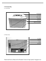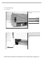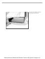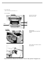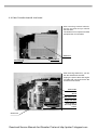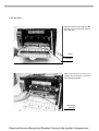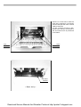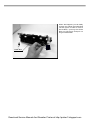
1
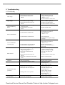
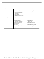
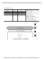
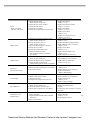
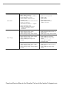
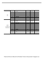
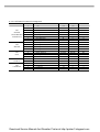
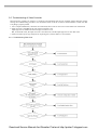
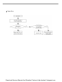
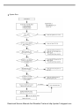
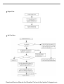
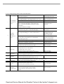
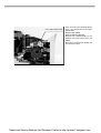
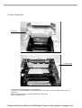
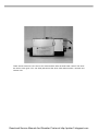
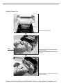
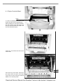
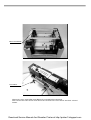
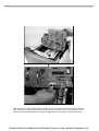
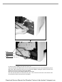
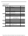
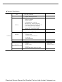
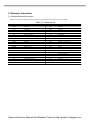
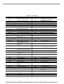
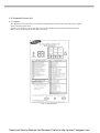
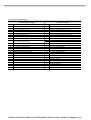
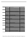
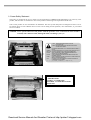
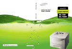
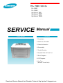
ML-7000 Series
ML-7000P
ML-7000N
QwikLaser 7000
QwikLaser 7000P
QwikLaser 7000N
SERVICE
Laser printer
Manual
Contents
1. Precautions
2. Reference Information
3. Product Information
4. Disassembly
5. Trouble Shooting
6. Exploded Views & Parts List
7. Block Diagrams
8. PCB Diagrams
9. Port Thru
(Network Printer Card)
Download Service Manual And Resetter Printer at http://printer1.blogspot.com
5. Troubleshooting
5-1 Print Quality
Error status
Dark Image
Light Image
Horizontal Density
Band.
Check
1. Check HVPS output voltage
2. Check terminal contact for
HVPS.
1. Check the toner quantity.
2. Check HVPS output voltage
3. Check the terminal contact for
HVPS.
1. Compare new image cartridge
with present one
2. Contamination of Transfer
Roller
1. Contamination of Fuser Unit
2. Contamination of Heat roller
Print Contamination
3. Contamination of OPC Drum
1. Contamination of Fuser Unit
Toner on Backside
of printer page
Back Ground
Vertical Black Streak
and band
Vertical White Streak
2. Contamination of transfer Roller
3. Contamination fo paper path
1. Check HVPS output voltage
2. OPC Drum contamination or
image cartridge life
3. Check the contamination of
PTL lens
4. Check the terminal contact for
HVPS.
5. Check the contamination fo transfer
roller.
1. OPC Drum scar
2. OPC Drum damage
1. Contamination of LSU window
1. OPC Drum scar or particle
2. Heat roller scar or particle
3. Develope roller scar or particle
Partial Black Image
(periodic)
4. Charge roller scar or particle
Partial White Image
(not periodic)
1. OPC Drum scar or particle
2. Check the cartridge life
Solution
1. Refer to HVPS output spec
- Replace the engine board
- Refer to “4 - 11”
2. Fix the terminal to contact well.
1. Replace image cartridge.
2. Refor to HVPS output spec.
-Replace the engine board.
3. Fix the terminal to contact well.
1. Replace image cartridge
2. Replace transfer roller
1. Clean Fuser Unit or change
If not improved, replace it.
2. Clean Heat Roller
- Refer to “4-5”
3. Clean OPC Drum.
If not improved, replace image
cartridge.
1. Clean Fuser Unit.
If not improved, replace it.
- Refer to “4-5”
2. Replace Transfer Roller
3. Remove the contamination on
paper path.
1. Refer to HVPS output spec
- Replace the engine board
2. Replace the image cartridge
3. Clean the lens with a soft
dry cloth
4. Fix the terminal to contact well.
5. Relpace Transfer Roller
1. Clean OPC Drum
2. Replace image cartridge
1. Clean LSU window
2. If not improved,
replace image cartridge
1. Clean OPC Drum & roller
2. Cleaning heat roller
3. Clean the develope roller.
If not improved,
replace image cartridge.
4. Clean the charge roller.
If not improved,
replace image cartridge.
1. Clean OPC Drum
2. Replace image cartridge
Download Service Manual And Resetter Printer at http://printer1.blogspot.com
Error status
No image (all white)
All Black Image
Check
1. Check HVPS voltage
2. Check the GND OPC contact.
- Contact among GND OPC
contact points.
- Image cartridge.
- GND OPC terminal on frame
- GND OPC terminal on the
engine board
- Confirm the voltage between
GND-OPC and GND-Frame.
: -130V approx
3. Check LSU operation.
- Refer to DCU control “05”
4. Compare new video board
with present one.
5. Toner empty
1. Check the charger voltage
2. Check the terminal contact
3. Compare new video board with
present one
Solution
1. Refer to HVPS output spec.
- Replace the engine board
2. Fix contact points to fit well.
3. Replace the LSU.
-Refer to “4-8”
4. Replace the video board.
5. Replace the image cartridge.
1. Refer to HVPS output spec
- Replace the engine board
2. Replace terminal
3. Replace video board
Download Service Manual And Resetter Printer at http://printer1.blogspot.com
5-2 HVPS Output Spec
DCU
CHARGER
TRANSFER “-”
TRANSFER “+”
BIAS
SUPPLY
OPC GND
CODE NO.
“01”
“02”
“03”
“04”
“04”
¶
HVPS OUTPUT
- 1.55 KV
-1KV~ -1.4KV
+1.8 KV
- 500 V
- 700 V
- 130 V
REMARK
1. Turn off the printer
2. Open the rear cover and disassemble
the cover-shield.
3. Connect the DCU on engine board and
close the rear cover.
4. Open the top cover.
5. Remove image Cartridge.
6. Push the Cover Open Switch
7. Select the Diagnostic mode and
measure HVPS output.
° Recommanded Test Equipment
- DVM -High Voltage Probe
Download Service Manual And Resetter Printer at http://printer1.blogspot.com
5-3 Malfunction
Error status
No Power
Internal Error 11
(Fuser Error)
Cover open
Check
1. Check FUSE
- F1(8A), F2(5A) OPEN.
2. Check FUSE.
- F3(250V/3A) OPEN.
1. Check Fuser unit
- Thermostat open
- hallogen lamp defect
Normal : 110V version - 2~3•
220V version - 5~6•
2. Check themistor wire assembly defect.
Normal : 2~400k•
3. Check SMPS
- CN2 conection on SMPS
- Fuse(F2) open
- Defect of component related to Fuser
control.
4. Check Engine Board
- CN7 connection
- Fuser control line:
Cn5-2 level (Lamp on : 0.2V, Lamp off:24V)
Check the Cover Open operation
1. Cover open unit defect
2. Cable damage and connection
3. Engine board defect
Solution
1. Replace SMPS.
- Refer to “4-12”
2. Measure the resistance +5V and GND.
(Engine board CN5-pin6 and CN5pin9). If find the short circuit, replace
the Engine board.
To disassemble the Fuser unit,
refer to “4-5”.
1. If the thermostat of the fuser unit
is opened. replace it.
2. If the thermistor wire of the fuser unit
is defected, replace it.
3. If the fuser unit is normal,
replace SMPS.
4. If not normal operation after replacing
it, replace the engine board.
1. Replace cover open Unit
-Refer to “4-6”
2. Replace cover open switch
assembly, and connect properly.
3. Replace the engine board.
Download Service Manual And Resetter Printer at http://printer1.blogspot.com
Error status
Jam 2
“Paper is stopped
just after exit sensor”
Duplex Jam 1
Duplex Jam 2
PTL Error
(Pre Transfer Lamp)
Toner Empty
OUT-BIN Full
Internal Error 20
(Engine Error)
Check
1. Check the exit sensor.
- Refer to DCU mode “08”
2. Check the exit sensor actuator.
3. Check the Exit Roller.
4. Check the Cover Rear.
5. Check the Contamination of Fuser Unit
Solution
1. Replace Exit sensor.
- Refer to “4-11”
2. Replace Exit sensor actuator.
- Refer to “4-5, 6-6”
3. Replace Exit Roller.
- Refer to “4-3, 6-1”
4. Replace Cover Rear.
- Refer to “6-1”
5. Replace or Clean Fuser Unit
- Refer to “4-5, 6-6”
1. Replace Duplex Clutch.
- Refer to “4-6”
2. Replace the DS1 on Engine Board.
3. Replace Duplex sensor 1 actuator.
- Refer to “4-11”
4. Replace Cover Rear.
- Refer to “6-1”
5. Replace bracket duplex unit
- Refer to “6-8”
6. Replace duplex solenoid ass’y.
1. Replace the DS2 on Engine board.
2. Replace Duplex sensor actuator.
3. Replace Gear of shield pcb
- Refer to “4-11, 6-7”
1. Check the operation of Duplex Clutch
- Refer to DCU mode “12”
2. Check the Duplex sensor 1.
- Refer to DCU mode “07”
3. Check the Duplex sensor 1 actuator.
4. Check the Cover Rear.
5. Check the bracket duplex unit
6. Check the duplex solenoid.
The resistance of duplex solenoid:
40~50 ohm.
1. Check the Duplex sensor 2.
- Refer to DCU mode “07”
2. Check the Duplex sensor 2 actuator.
3. Check the Gear of shield pcb
- Check all the gear for correct installation
1. Check the LED Array.
1. Replace LED Array.
2. Check the cable connection or wire defect.
- Refer to “6-2”
3. Check Joint board.
2. Replace harness or reconnection.
3. Replace Joint board.
- Refer to Disassembly
1. Check image cartridge life
1. Replace image cartridge.
2. Check Toner sensor contact.
2. Replace harness or reconnection.
3. Check Joint board
3. Replace Joint board.
4. Compare new image with present on.
- Refer to “4-4”
4. Replace image cartridge.
1. Check OUT-BIN sensor.
1. Replace OUT-BIN sensor.
- Refer to DCU mode “09”
2. Replace OUT-BIN sensor
2. Check OUT-BIN sensor actuator.
actuator.
3. Check cable connection or wire defect
3. Connect the cable correctly or replace
the cable.
1. Check the Cable between Engine and
1. Connect the cable correctly or
Video controller.
replace the cable.
(Engine board CN10®Video controller
- Refer to “4-4”
M
board J11.)
2. Replace Engine board.
2. Engine board defect.
Download Service Manual And Resetter Printer at http://printer1.blogspot.com
Error status
Internal Error 10
(Scanner Error)
Check
1. Check the DC supply for laser
scanning unit
2. Check laser scanning unit
- Refer to DUC mode “05”
3. Check the cable connection and defect
4. Engine board.
1. 1st cassette feeding
1) Check the operation of Pick-up Clutch
- Refer to DCU mode “06”
2) Check PAD of Pickup roller.
3) Check the Gear of Pickup Unit.
Jam 0
1. Paper is not
exitted from cassette
2. Paper is stopped
before feed sensor.
Jam 1
“Paper is stopped
on feed sensor”
4) Check paper installation in cassette
2. Multi purpose feeding
1) Check the operation of
multi purpose Clutch
- Refer to DCU mode “13”
- Check MP solenoid.
The resistance of MP solenoid 70~80•
2) Check PAD of Pickup roller
3) Check Joint board
Measure the CN503-2pin
4) Check the Gear of multi Purpose
Pickup Unit
5) Check cable connection or wire defect.
3. Second cassette feeding
1) Check Pickup Clutch for SCF.
- The resistance of SCF solenoid: 70~80•
2) Check PAD of Pickup roller
3) Check the Gear of pickup Unit
4) Check paper installation in cassette.
5) Check cable connection or wire defect.
1. Check the Feed sensor.
- Refer to DCU mode “08”
2. Check the Feed Sensor actuator
3. Check the paper installation in
cassette.
Solution
1. If +5Vs for laser diode isn’t supplied.
check the cover switch assembly for
+5Vs and fix it,
2. If the DC power supply for laser
scanning unit has normal operation,
replace the laser scanning unit
3. Replace cable and connect properly.
4. If not normal operation after replacing
it, replace the engine board.
1. Replace the Pick-up solenoid on
Engine Board.
- Refer to “4-11”
2. Replace PAD.
- Refer to “4-7, 6-5”
3. Replace Pickup Unit Gear.
- Refer to “4-7, 6-5”
4. Install paper properly.
1. Replace MP solenoid.
If not normal operation after replacing
it, replace the engine board.
- Refer to “4-11”.
2. Replace PAD
- Refer to “4-9, 6-4”
3. Replace Joint board.
- Refer to “4-4”
4. Replace Pickup Unit Gear.
5. Connect the cable correctly
or replace the cable.
1. Replace the pick-up clutch for SCF.
If not improved, replace SCF board
2. Replace PAD.
- Refer to “6-11”
3. Replace Pickup Unit Gear.
- Refer to “6-11”
4. Reinstiall paper properly.
5. Connect the cable correctly, or
replace the cable.
1. Replace Feed Sensor.
- Refer to “4-11”
2. Replace Feed Sensor actuator.
- Refer to “4-11, 6-2”
3. Reinstall paper properly.
Download Service Manual And Resetter Printer at http://printer1.blogspot.com
Error status
Main Motor
Paper Empty
Check
- Refer to DCU mode “00”
1. Check the supply voltage. (+24Vdc)
Engine board CN1 -2,5 pin
2. Check the Motor cable for cuts or
pinched wiring.
3. Check the resistance for Motor between
pin No. 1 to 3(4 to 6)
The resistance of motor : 3• approx.
4. Check the Engine board.
5. Check Gear of Motor Drive Unit.
- Check all the gear for correct
installation.
1) 1’st Cassette Feeder
1. Check the paper empty sensor
- Refer to DCU mode “07”
2. Check the paper empty sensor actuator.
2) Multi Purpose Feeder
1. Check the paper empty sensor for MP.
- Refer to DCU mode “07”
2. Check the MP paper empty sensor
actuator.
3) Second Cassette Feeder
1. Check the paper empty sensor for SCF
- Refer to DCU mode “07”
2. Check the paper empty sensing actuator
for SCF.
Solution
1. Replace to cover open unit.
2. Replace cable
3. Replace Motor.
4. Replace Engine board.
5. Replace Motor Drive Unit
- Refer to “4-6, 6-9”
1. Replace the paper empty sensor on
Engine board.
2. Replace paper empty sensor actuator.
1. Replace MP sensor assembly.
2. Replace MP paper empty sensor
actuator.
If not improved, replace
the engine board
1. Replace the paper empty sensor on
S.C.F board.
2. Replace MP paper empty sensor
actuator.
Download Service Manual And Resetter Printer at http://printer1.blogspot.com
5-4 .Connector Pin Assignment
5-4-1. Engine Board Connector Pin Assignment
CONNECTOR
PIN-NO
1
2.5
CN1
3
MOTOR
4
6
CN2
1
DUPLEX
1
1
CN3
2
FAN
3
1
CN4
2
CASSETTE
3
BOARD
4
1
2
3,5,7
CN5
4
SMPS
6,8,10
9,11,12
13,14,15,16
1,2,3
4
5
6
7,9
CN6
8
JOINT BOARD
10
INTERFACE
11,13
12
14
15,17
16
18
CN7
1
THERMISTOR
2
1
CN8
2
DCU
3
4
DESCRIPTION
MOTOR_PB*
+24V
MOTOR_PB
MOTOR_PA*
MOTOR_PA*
+24V
D_CLUTCH
+24V
NC
FAN
CAST_SENS1
CAST_SENS2
CAST_SENS3
DGND
+24VS2
FUSERON
AGND
+5Vs
+5V
DGND
+24VS2
+5V
MP_CLUTCH
+5Vs
Q_LAMP
+24VS2
SCF_READY
STS_SCF
AGND
MP_PAPER
TONER
DGND
CMD_SCF
OPT_CLK
THERMISTOR
THERMISTOR
+5V
DCU_DATA
DCU_CLK
DGND
IDLE
+24V
+24V
+24V
+24V
+24V
+24V
+24V
+24V
NC
+24V
H
H
H
DGND
+24V
+24V
AGND
+5V
+5V
DGND
+24V
+5V
L
+5V
L
+24V
H
PULSE
AGND
H
H
DGND
PULSE
PULSE
+5V
PULSE
CLOCK
DGND
ACTIVE
PULSE
+24V
PULSE
PULSE
+24V
+24V
L
+24V
NC
L
L
L
L
DNGD
+24V
L
AGND
+5V
+5V
DGND
+24V
+5V
0.7V
+5V
0.7V
+24V
L
PULSE
AGND
L
L
DGND
PULSE
PULSE
+5V
PULSE
CLOCK
DGND
IN/OUT
O
O
O
O
O
O
I
I
I
O
O
O
I
I
I
I
O
O
I/O
O
-
Download Service Manual And Resetter Printer at http://printer1.blogspot.com
CONNECTOR
PIN-NO
1.4
2
3
5
CN9
6
LSU
7
8
9
10
1
2,17,19,20,21
22,23,24
3
4
5
CN10
6
VIDEO
7
CONTROLLER
8
INTERFACE
9
10
11
12
13,15,16,18
25,27,28
14
DESCRIPTION
DGND
VDO
LDON
+5Vs
HSYNC
LREADY
PMOTOR
AGND
+24VS2
EBUSY
IDLE
DGND
H
H
+5V
H
H
+24V
AGND
+24V
H
ACTIVE
DNGD
L
L
+5V
L
L
L
AGND
+24V
L
IN/OUT
O
O
I
I
O
O
DGND
DGND
DNGD
-
EMSG
EXIT_PAP
CCLK
PRINT
VDI
CPRDY
PSYNC
READY
HSYNC
NC
H
H
H
H
H
H
H
H
NC
L
L
PULSE
L
L
L
L
NC
O
O
I
I
I
+5V
+5V
+5V
-
CMSG
H
O
O
O
-
I
Download Service Manual And Resetter Printer at http://printer1.blogspot.com
5-4-2. Joint Board Connector Pin Assignment
CONNECTOR
CN501
JOINT BOARD
INTERFACE
CN502
SCF
INTERFACE
CN503
MP_CLUTCH
CN504
Q_LAMP
CN505
MP_SENSOR
CN506
TONER
PIN-NO
1,2,4
3
5
6
7
8,10
9
11
12,14
13
15
16,18
17
1
2
3
4
5
6
7
8
1
2
1
2
1
2
3
1
2
3
DESCRIPTION
+5V
MP_CLUTCH
Q_LAMP
+5Vs
SCF_READY
+24VS2
STS_SCF
MP_PAPER
AGND
TONER
CMD_SCF
DGND
OPT_CLK
+5V
AGND
+24V
STS_SCF
CMD_SCF
OPT_CLK
SCF_READY
DGND
+24V
MP_CLUTCH
+5V
Q_LAMP
MP_SENSOR
DGND
+5V
+5V
TONER
AGND
IDLE
+5V
L
L
+5V
H
+24V
PULSE
H
AGND
H
PULSE
DGND
PULSE
+5V
AGND
+24V
PULSE
PULSE
PULSE
H
DGND
+24V
+24V
+5V
+5V
H
DGND
+5V
+5V
H
AGND
ACTIVE
+5V
0.7V
0.7V
+5V
L
+24V
PULSE
L
AGND
L
PULSE
DGND
PULSE
+5V
AGND
+24V
PULSE
PULSE
PULSE
L
DGND
+24V
L
+5V
L
L
DGND
+5V
+5V
L
AGND
IN/OUT
O
O
I
I
O
I
O
O
O
I
I
O
O
O
I
O
-
Download Service Manual And Resetter Printer at http://printer1.blogspot.com
5-4-3. S.C.F Board Connector Pin Assignment
CONNECTOR
CN1
ENGINE
JONIT BOARD
INTERFACE
CN2
MOTOR
CN3
DCU
CN4
PICK UP
CN5
CASSETTE
PIN-NO
1
2
3
4
5
6
7
8
1
2
3
4
1
2
3
4
1
2
1
2
3
4
DESCRIPTION
+5V
AGND
+24V
STS_SCF
CMD_SCF
OPT_CLK
SCF_READY
DGND
MOT_PA
MOT_PB
MOT_PA*
MOT_PB*
+5V
DCU_IN/OUT
DCU_CLK
DGND
+24V
CLUTCH
CASET_1
CASET_2
CASET_3
DGND
IDLE
+5V
AGND
+24V
PULSE
PULSE
PULSE
H
DGND
+24V
+24V
+24V
+24V
+5V
PULSE
CLOCK
DGND
+24V
+24V
H
H
H
DGND
ACTIVE
+5V
AGND
+24V
PULSE
PULSE
PULSE
L
DGND
PULSE
PULSE
PULSE
PULSE
+5V
PULSE
CLOCK
DNGD
+24V
L
L
L
L
DNGD
IN/OUT
O
I
I
O
O
O
O
I/O
O
O
I
I
I
-
Download Service Manual And Resetter Printer at http://printer1.blogspot.com
5-5 .Troubleshooting of Video Controller
Most electronic products are sensitive to connectors and assemblies that are not complete seated. Therefore, before
starting the troubleshooting procedure, do a mechanical check of all the connectors and assemblies to make sure that
everything is properly seated.
1. For a complex malfunction, check first for a bad weld, short circuit or loose wire on the solder area of the board
2. Input low level is standard for the TTL logic level below 0.8V.
Input high level is standard for the TTL logic level above 3.5V.
But, for PowerPC 603e, the input low level is less than 0.8V, and the input high level is more than 2.0V.
3. USE an oscilloscope or logic analyzer for inspecting the crystal oscillator or its waveform.
5-5-1. Troubleshooting Flow Chart
Download Service Manual And Resetter Printer at http://printer1.blogspot.com
Power Error
Download Service Manual And Resetter Printer at http://printer1.blogspot.com
System Error
Download Service Manual And Resetter Printer at http://printer1.blogspot.com
Engine Error
Self Test Error
Download Service Manual And Resetter Printer at http://printer1.blogspot.com
Parallel Interface Error
Printing Error
Download Service Manual And Resetter Printer at http://printer1.blogspot.com
5-5-2. Troubleshooting Table of Video Controller Board
NO.
Error Type
1
The backlight
of LCD is not
lit up
2
It doesn’t
displayed
characters on
LCD
3
White copy
4
DRAM Error
5
EEPROM
6
ROM Error
7
Engine Error
Parallel
Interface
Error
General descriptions of
troubleshooting
8
9
Ckeck List
Power cord connection
Vcc voltage(nominal is +5V) level
Vcc voltage should be in the range between+4.38-+5.2V
Short Between Vcc and GND
Mutual connection of engine, key panel to LCD
panel’s connected cable(10pin), video board to key
panel’s connected cable(20pin) and engine interface
cable(28pin)
The pin of connector is straigh.
Mutual connection of panel cabel(10pin)
video board to key panel’s connected cable(20pin)
Any component damage on a video controller board.
Any foreign conductive chips of solder or material
is on the video controller board or is laid between
IC pins after power off.
Reset Error:Reset signal is normal high during operation
System source clock is a 50ß÷
Check point : U16(FS741)’s pin No.6,
The output clock of QP17000 is a 25ß÷
.
Repair
Connect the power cord
Refer to the section of
Engine troubleshooting
Repair board
Connect the cable to
connector
Confirm the connection
of connector
Repair or replace it
with appropriate tools.
If uanable to do this,
replace video board.
Remove any foreign
conductive chips on the
video controller board.
Replace the FS741
The input clock of CPU(U26) and U24 is a 25ß÷
.
Replace the board
The video data colck source is a 62.7639ß÷
at OSc2
The input clock of U31 is a 62.76397ß÷
.
The output clock of U31 is a 16ß÷
.
The input clock of U2’s pin No.125 is a 16ß÷
.
Replace the board
°·
Check the normal operation of HSYNC* and PSYNC*
Active low impulse
°·
Check the DRAM address signals.(pin No. 17-20, 23-28 : U20, U290)
°·
Check the DRAM data signals. (pin No. 2-5. 7-10. 33-36. 38-41 : U20, U29)
°·
Check the EEPROM clock signal. (pin No. 2 : U1)
°·
Check the EEPROM data signals. (pin No. 3,4 : U1)
°·
Check the ROM chip select signals and read signal (pin No. 12,14)
°·
CHeck the ROM data signals. (pin No. 15-22, 24-31 : U25, U27, U30, U32)
°·
Refer to the section of Engine troubleshooting
Refer to USER’s manual
°·
CHeck the operation of printer driver.
Replace the printer
°·
Check the printer cable(bidirectional cable)
cable
°·
Please refer to the user’s manual.
°·
If you can’t fix the trouble of video controller
Replace the board
board, replace the video board by the verified
board.
Download Service Manual And Resetter Printer at http://printer1.blogspot.com
4. Disassembly
4-1 Front View
°
Control Panel
Cover Open
Power Switch
°
Cover Tray
Cover Front
°
°
°
Paper Level Indicator
°
4-2 Rear View
Cover Rear
Controller
°
Cassette
Power Inlet
°
°
Download Service Manual And Resetter Printer at http://printer1.blogspot.com
4-3 Cabinet Disassembly
4-3-1. Cover Right
Remove the screws and open the
Cover Rear.
°
Cover Rear
°
Screw
Cover Right
Screw
In order to remove the Cover Right.
Please see the hook which locks
the cabinet to the frame, right hand
should first grab the hook and pull it
out for releasing the hook from the
frame.
Hook
Download Service Manual And Resetter Printer at http://printer1.blogspot.com
The left hand should slide the
Cover Right to the backward.
Download Service Manual And Resetter Printer at http://printer1.blogspot.com
4-3-2. Cover Left
Remove screw and open the Cover
Rear.
Screw
Please see the hook of the Cover
Left. Pull the Hook and release it
from the frame.
Hook
Slide the Cover Left to the
backward with pulling the hook out.
The Cover Left can be easily
removed.
Pull
Download Service Manual And Resetter Printer at http://printer1.blogspot.com
4-3-3. Cover Front
Please see the MP tray disassembly. (4-9)
4-3-4. Cover Main
Cover Open
Open the Cover Open.
Remove two screws.
Cover Top
Screw
Screw
Cover Main
Up
See the hooks.
Push the hooks up and pull them
upward.
With holding Cover Main, remove
the panel wire.
Download Service Manual And Resetter Printer at http://printer1.blogspot.com
4-3-5. Cover Rear
Stripe
Open the Cover Rear.
Detach the stripe by pushing the
stripe.
There is a hook holding the stripe.
®
®
Cover Rear
After detaching the stripe from the
Cover Rear,
Release the Cover Rear from the
hinge.
Hinge
Download Service Manual And Resetter Printer at http://printer1.blogspot.com
4-4 Video Controller board & Joint board
After removing external cabinet,
see the 5 screws and you should
remove them.
The Shield ICU is important for EMI
and protection for Controller.
°
Shield ICU
Joint Board
Screw
After removing Shield ICU, you can
see the assembled controller.
Unplug the panel cable and engine
I/F cable with care and remove the
screws from the frame.
Panel Cable
Controller
Board
RAM Simm Socket
Engins I/F cable
Flash SIMM or
Postscript SiMM
Socket
Frame ICU
Download Service Manual And Resetter Printer at http://printer1.blogspot.com
Remove the screws which hold the
Bracket ICU to the frame and detach controller from the frame.
You can see the Frame ICU.
Screw
Parallel
I/F
reserved for
Network
reserved for
Serial
Screw
ASIC(QP1700)
ASIC
(Powerbridge)
Connector for
Network
ASIC
(Hype chip)
Power PC processor
Video Controller Board
Download Service Manual And Resetter Printer at http://printer1.blogspot.com
4-5 Fuser Ass’y
Open the Cover Rear and see the
screws and unscrew and remove
the Cover pcb.
Screw
Cover pcb
for engine B’d
After removing the Cover pcb,
unplug the Thermistor connetor
from the Engine Board.
Thermistor
connector
Download Service Manual And Resetter Printer at http://printer1.blogspot.com
See the 4 screws which hold the
fuser assy to the frame. You should
unscrew and pull the fuser out and
it will be removed.
The AC connector for fuser is designed to be directly connected to
the AC socket which is positioned
in the frame.
Screw
Screw
Screw
Screw
exit sensor
actuator
< Fuser Ass’y >
Download Service Manual And Resetter Printer at http://printer1.blogspot.com
When Jam happens, you can easily
remove it by pulling the Guide Rear
out like figure. In order to remove
Guide Rear, opening the Guide
Rear out like figure and pull out
hinge of Guide Rear.
®
Guide Rear
®
Download Service Manual And Resetter Printer at http://printer1.blogspot.com
4-6 Bracket Motor Ass’y & Cover Open Switch Unit
Bracket Motor ass’y is located in
the right-upper side. Remove 7
black screws and detach the ass’y
from the frame and unplug the
motor connector from the motor.
Bracket Motor Ass’y
You can see the Bracket Motor ass’y.
Motor and several gears are assembled in one gear bracket.
Motor
< Bracket Motor Ass’y >
Download Service Manual And Resetter Printer at http://printer1.blogspot.com
Cover Open Switch unit
After removing the Bracket Motor
ass’y, you can see the Cover Open
Switch Unit.
Remove the SMPS.
Refer to SMPS & Bracket
Duplex Ass’y disassembly (4-12)
Detach two Connectors form the
SMPS.
Remove 2 screws and detach the
unit from the frame.
Download Service Manual And Resetter Printer at http://printer1.blogspot.com
4-7 Pickup Ass’y
After running about more than
100,000 pages, the pickup ass’y
may be needed to be replaced
depending on feeding quality.
Remove the screw of Bracket
Support and tension spring.
Pickup Ass’y
Tension Spring
Screw
Lift Guide Front Duplex and
remove the 3 mounting screws of
Pickup Ass’y.
Guide Front Duplex
Screws
Download Service Manual And Resetter Printer at http://printer1.blogspot.com
4-8 Laser Scanner Unit
Cover Top
Cap-wire LSU
Laser Scanner Unit is located in the upper frame.
In order for LSU disassembling, disassemble the Cover Main, you should take off the left and
right cover.
There is wiring protection cover(Cap Wire LSU)for LSU wires.
Remove Cap wire LSU.
Download Service Manual And Resetter Printer at http://printer1.blogspot.com
There are two wires for LSU. One is LSU motor and the other is Laser beam control. The wires
are wire to wire types. You can easily disconnect the wires. After disconnection, unscrew and
remove LSU.
Download Service Manual And Resetter Printer at http://printer1.blogspot.com
4-9 Multi Purpose Tray
Remove the Cover main.
Hook
See the Links which hold the MP tray
in the both side.
Hold the Links and pull it to the arrow
direction.
Hold the MP tray and pull it to the
arrow direction.
Download Service Manual And Resetter Printer at http://printer1.blogspot.com
Screw
Hook
Cover Front
After detaching the Tray MP, see the screws and remove them.
Remove the hook and release the Cover Front by releasing the hook.
Download Service Manual And Resetter Printer at http://printer1.blogspot.com
Screw
Screw
Screw
Screw
After removing Cover Front, detach
the MP ass’y by unscrewing 4
screws.
Before detaching MP Ass’y, unplug
the MP solenoid and MP sensor
connector from the Joint Board.
< MP Assy >
Download Service Manual And Resetter Printer at http://printer1.blogspot.com
4-10 Control Panel
LCD Ass’y
Cover Top
Cover Open
First lift up Cover Main and see the panel wire and disconnect the wire from the panel board. And
next step is to remove the panel board which is located in the Cover Top.
Control panel consists of LCD ass’y and Key&LED ass’y.
Remove Key&LED ass’y and remove LCD ass’y.
Download Service Manual And Resetter Printer at http://printer1.blogspot.com
LCD Ass’y
Hook
Cover Top
Hinge
After removing Key&LED ass’y, release the hook of LCD assy from Cover Top and see the hinge
for LCD ass’y in the cabinet and release them.
You should spread the hinge of LCD ass’y.
But be careful not to damage the hinge.
Download Service Manual And Resetter Printer at http://printer1.blogspot.com
4-11 Engine Controller Board
Paper
In order for disassembling PCU, the
printer should be turned upside down.
When turned over, toner may contaminate LSU window. Open the Cover Top
and you should insert one paper into
the inner like above figure.
Open the Cover Rear and remove the
Cover PCB.
Screw
wire
After removing Cover Rear, disconnect
all wires from the PCU. and then
remove the screw of Ground Shield
SMPS, Turn over the printer.
Download Service Manual And Resetter Printer at http://printer1.blogspot.com
Bar Cross Bottom
CST Sensor
After turning over, remove Bar cross Bottom by unscrewing them 8 screws.
Next remove the CST Sensor and remove the screws in the PCU which are black colored
screws.
Download Service Manual And Resetter Printer at http://printer1.blogspot.com
After unscrewing, lift the PCU like above figure. And you can see the connector which are LSU’s
and ‘Video I/F’s’. Unplug them with care. Be careful not to be hurt to your hands when you
disconnect the wires because the connection is tight and you may pull the connectors strongly.
Download Service Manual And Resetter Printer at http://printer1.blogspot.com
PCU room
< PCU Ass’y >
Above is to show the disassembled PCU and Frame. PCU Assy has some sensor, some
actuator, solenoid and Shield plate and HVPS circuit. Service man could ask the Assy or repair
parts.
Download Service Manual And Resetter Printer at http://printer1.blogspot.com
Screw
Screw
Screw
Screw
In order to remove SMPS, first remove Cover Left.
Use your left hand to release hook from the frame and slide the Cover Left to backward by use of
right hand. After removing Cover Left, you can see the SMPS. Unplug the power connector and
release the wire from the wire guide of the SMPS.
Remove four screws and separate SMPS from the frame.
You can see the fuser AC connector and +5V, +24V connector which are connected to the
microswitches. Detach the wires from the SMPS.
Download Service Manual And Resetter Printer at http://printer1.blogspot.com
+24V
AC Connector
+5V
There are 4 connectors to the SMPS. The power connector is +5V and +24V output from SMPS.
AC for fuser is AC output from SMPS to the fuser. And there are microswitches whice are
attached to the upper frame and which are attached to the upper frame and which are shorted
when Top cover is closed, namely interlock Switches for +24V for HVPS, motor and for +5V for
Laser beam.
Bracket Duplex Ass’y
The Bracket Duplex Ass’y is located in the left upper side. Remove the screws and detach the
ass’y from the Frame.
In order to remove the connector of Solenoid, first remove Engine Controller Board.
Refer to Engine Controller Board disassembly (4-11)
Download Service Manual And Resetter Printer at http://printer1.blogspot.com
4-13 Transfer Roller Ass’y
Holder Transfer Roller
Open the Cover Top, you can see colored levers at each side of Transfer Roller, push the levers
which is attached in the Holder transfer Roller to release the Ass’y.
Download Service Manual And Resetter Printer at http://printer1.blogspot.com
3. Product Information
Engine Specifiation
Item
Engine
Speed
Resolution
Imaging
Toning/Fusing
WarmUp time
FPOT
Duty Cycle
Size(WDH)
Weight
Power Consumption
Noise Level
Input Capacity
Optional Input
Output Capacity
MP Tray
Envelop Feeder
Paper
Handling
Imaging
Catridge
Type of Media
Duplexing
Paper Sensor
CRU type
CRU Life
Cleaning System
Charging/Transfer
Toner Sensor
Toner saving
Control Panel
Others
Paper Level Indicator
Power Switch
Descriptions
17 PPM
600 DPI +RET
Eletrophotography
Non-mag monocomponent/contact
Less than 60 secs
Less than 13 secs
Maximum 50,000 pages per month
427 ° 442 ° 301mm
Less than 16.5Kg (36.4lb)
340W Avg/ 34W Sleep
Printing : ° 50dB
Standby : ° 36dB
Sleep : Background noise
500 sheets
500 sheets (40 envelopes)
250 sheets Facedown
100 sheets (10 envelopes)
supported by Multi-Purpose tray, optional cassette
°Cassette : A4, LTR, FO, LEG, EXE, ISO B5
°MP Tray : Legal~A6, OHP, LABEL
COM-10, MON, DL, C5, C6
°Optional Cassette : A4, LTR, FO, LEG
COM-10, MONARCH, DL, C5
Paper : A4, LTR, FO, LEG
Yes
Single cartridge Replacement
8,000 pages at 5% coverage
Mechanical Cleaning
Contact Charging & Transfer
Yes
Yes
°8° 2 LCD
°LCD Display angle adjusting
°Backlighting
Visible Mechanism
Front & Left side, Push botton
Remarks
Letter
N/N condition
standby mode
not packaged
Blow Fan off
Universal
No faceup mode
Download Service Manual And Resetter Printer at http://printer1.blogspot.com
Controller Specification
Item
CPU
Emulation
Memory
Interface
Controller
AIS/AES
Font
Port Thru
(Network Printer Card)
Device Driver
Descriptions
Power PC, 100MHZ
°Default : PCL6
°Option : Postscript Level 2
°4MB Standard
°Max up to 68MB
°Speed : 60nS
° DRAM Module’s Features
°Refresh Time : 2048 Cycles/32mS
°Fast Page Mode with Extended data out
°CAS-before-RAS refresh capability
°TTL compatible inputs and outputs
°Single +5V °10% power supply
°2, 4MB Flash memory option
°Postscript : 12MB Standart
°IEEE 1284 B type
Option :
Serial RS 232C
InfraRed Adaptor connector
Local Talk,
Internal Network
Y/Y
35 Intellifont, 10 True Type, 1Bit Map
°Ethernet
°10 base T
°SNMP in MIB
°TCP/IP
°Netware, Windows, OS/2, Unix, Mac
PCL : Windows 3.1/95/NT, DOS
Remarks
P.S Simm Module
TCP/IP, SPX/IPX
Apple Talk,
NetBEUI/NetBios
Download Service Manual And Resetter Printer at http://printer1.blogspot.com
2. Reference Information
2-1 Abbreviations and Acronyms
Tables 2-1 and 2-2 List abbreviations and acronyms which may be found in this sevice manual.
Table 2-1. Abbreviations
Abbv
amps
Definition
amperes
ass’y
badac
assembly
bad assess
bps
clk
cm
CON
GND
HLDA
HLDAR
HLDR
HOR
in
INTA
INT
INTR
I/O
mpx
bits per second
clock
centimeter(s)
connector
ground
hold acknowledge
hold acknowledge received
hold request
horizontal
inch(es) or input
interrupt Acknowledge
Interrupt
Interrupt request
Input and Output
multiplex
Abbv
lb
lin
lock
mm
neg
od
OSC
OUT
PIC
pos
pot
psynrq
pwr
qty
sw
sync
tach
Vcc
vert
Vp-p
VR
Definition
pound(s)
linearity
bus lock
millimeter(s)
negative
open drain
oscillator
output
picture
positive or position
potential
page synchronizaton request
power
quantity
switch
synchronous or
synchronization
tachometer
collector supply valtage(dc)
vertical
peak-to-peak voltage
variable resistor
Download Service Manual And Resetter Printer at http://printer1.blogspot.com
Table 2-2. Acronyms
Acronym
ABL
Definition
Automatic Blanking Limiter
Acronym
IDE
ACC
ADC
ADS
Automatic Color Control
Analog to Digital Converter
Address/Data Status
IF
IPM
ISA
Definition
Intelligent Drive electronics or
Imbedded Drive Electronics
Intermediate Frequency
Images Per Minute
Industry Standard Architecture
ALE
ASCII
Address-Latch Enable
American Standard Code for
Information interchange
Basic Input/Output System
Band Pass Second
Bits Per Second
Cold Cathode Fluorescent Tube
Color Graphics Adapter
Complementary Metal Oxide
Semiconductor
Central Processing Unit
Cathode Ray Tube
Customer Replacement Unit
Direct Memory Access or
Dynamic Memory Address
Direct Memory Access
Controller
Digital Voltmeter
KBC
LAD
Keyboard Controller
Local Address/Data Bus
LCD
LED
MCA
MDA
NC
NF
Liquid Crystal Display
Light Emitting Diode
Micro Channel Architecture
Monochrome Display Adapter
No Connection
Noise Fiqure or Noise Factor
PA
PBA
Power Amplifier
Printed Board Assembly
PBM
Primary Bus master
PCB
Printd Circuit Board
BIOS
BPF
BPS
CCFT
CGA
CMOS
CPU
CRT
CRU
DMA
DMAC
DVM
EEPROM
EGA
EISA
ESDI
FDC
FDD
FL
HDD
HPF
SCSI
SIO
SOP
SSOP
STN
SCC
TFT
TS
TSOP
Electronically Erasable Programmable read Only Memory
Enhanced Graphics Adapter
Extended Industry Standard
Architecture
Enhanced Small Device
Interface
Floppy Disk Controller
Floppy Disk Drive
Fluorescent Light(Lamp)
Hard Disk Drive
High Pass Filter
Small Computer Systems
Interface
Serial Input/Output Controller
Small Outline Package
Shrink Small Outline Package
Super Twisted Nematic
Serial Communications
Controller
Thin Film Transistor
Tri-State
Thin Small Outline Package
PCMCIA
PLCC
Personal Computer Memory
Card International Association
Plastic Leaded Chip Carrier
PMS
POST
Power Management System
Power On Self Test
PPM
Pages Per Minute
PQFP
QFP
RAM
ROM
RTC
SBM
Plastic Quad Flat Package
Quad Flat Package
Random Access Memory
Read Only Memory
Real-Time Clock
Secondary Bus Master
TSTN
UHF
VCO
VESA
VGA
Triple Super Twisted Nematic
Ultrahigh Frequency
Voltage Controlled Oscillator
Video Electronics Standard
Association
Video Graphics Array
VHF
XO
Very High Frequency
Crystal Oscillator
Download Service Manual And Resetter Printer at http://printer1.blogspot.com
2-2. Diagnostic Control Unit
2-2-1. Abstract
The diagnostic Control Unit(DCU) is useful for troubleshooting the Laser beam printer ML Series engines,
and for checking printer status.
The DCU can be used in common for ML series, but each model has several different code description.
Refer to the code description for ML-7000 in next page.
< Fig 1-1. ML-80 DCU >
Download Service Manual And Resetter Printer at http://printer1.blogspot.com
2-2-2. List of code description
Code Description
00
01
02
03
04
05
06
07
08
09
10
11
12
13
14
15
1. DIAGNOSTIC CODE
MAIN MOTOR OPERATING
MAIN HIGH VOLT ON / OFF TEST
THV (- ) ON / OFF TEST
THV (+) ON / OFF TEST
DEV, SUPPLY ON / OFF TEST
LSU OPERATING TEST
PICK UP CLUTCH ON
PE, DS1, DS2 SENSOR TEST
MP, EXIT, FEED SENSOR TEST
TOP & REAR COVER OPEN,
OUT BIN SENSOR TEST
FUSER TEST
HOT BURN TEST
DUPLEX CLUTCH TEST
MULTI PURPOSE CLUTCH TEST
THERMISTER 2 TEST
PAPER SIZE SENSOR TEST
78
00
01
02
03
04
05
20
21
22
23
50
60
62
68
61
64
69
70
71
72
73
74
75
76
95
2.STATUS CODE
SYSTEM ERROR
Ready to print from LEGAL paper tray
Ready to print form LETTER paper tray
Ready to print form A4 paper tray
Ready to print form EXEC paper tray
Ready to print from B5 paper tray
Ready to print from FOLIO paper tray
PRINT START (1st CASSETTE)
PRINT START (MULTI PURPOSE)
PRINT START (2’nd CASSETTE)
PRINT START (DUPLEX)
PAPER OUT
OPEN FUSER ERROR
LOW HEATER ERROR
OVER HESTER ERROR
WARM-UP
COVER OPEN ERROR
SLEEP MODE
NO PAPER or CASSETTE
PAPER JAM “0”
PAPER JAM “1”
PAPER JAM “2”
DUPLEX JAM “1”
DUPLEX JAM “2”
OUT BIN FULL
LSU NOT READY
Download Service Manual And Resetter Printer at http://printer1.blogspot.com
2-2-3. The Diagnostic Control Unit (DCU) Operating Guide
The DCU has functions as follows:
1) Engine Status and Error Code Display mode
¶ Display the engine status and error status code. Refer to List of Code Description.
°
2) Self-Test mode.
¶ When the engine is ready, this button starts printing a streak pattern.
°
3) Green mode
¶ Transfer high Voltage adjustment mode
With the power off, hold down the Self-Test button and turn on the pinter. Continue holding down the button
for 5 seconds to start Green mode.
4) Diagnostic Control mode.
¶ With the power off, hold down the 3 button (up/down, shift, stop/enter) and turn on the printer
Continue holding down the button for 5 seconds to start Diagnostic Control mode on the engine.
¶ The DCU has three diagnostic control buttons.
UP
: Steps the function of the other two buttons:
SHIFT : Controls the function of the other two buttons:
SHIFT+UP means step down and SHIFT+START means stop.
START : Stasrts or stops the current diagnostic test.
Code
00
01
02
03
04
05
Key
ENTER
SHIFT+STOP
UP
SHIFT+DOWN
ENTER
SHIFT+STOP
UP
SHIFT+DOWN
ENTER
SHIFT+STOP
UP
SHIFT+DOWN
ENTER
SHIFT+STOP
UP
SHIFT+DOWN
ENTER
SHIFT+STOP
UP
SHIFT+DOWN
ENTER
UP
SHIFT+STOP
UP
SHIFT+DOWN
Operation
Run Main Motor
Stop Main Motor
Increment DCU Code No. (01, MHV)
Decrement DCU code No. (13, MP)
MHV ON
MHV OFF
Increment DCU Code No. (02, THV Negative)
Decrement DCU code No. (00, Main Motor)
THV Negative ON
THV Negative OFF
Increment DCU Code No. (03, THV)
Decrement DCU code No. (02, MHV)
THV ON
THV OFF
Increment DCU Code No. (04, Dev)
Decrement DCU code No. (02, THV Negative)
DEV, SUPPLY ON
DEV, SUPPLY ON
Increment DCU Code No. (05, LSU)
Decrement DCU code No. (03, THV)
LSU Motor On
LSU Leady and LD On
LSU Motor OFF
Increment DCU Code No. (06, Pickup Clutch)
Decrement DCU code No. (04, Dev)
LED Display
Lighten ON LED
Lighten OFF LED
Lighten ON LED
Lighten OFF LED
Lighten ON LED
Lighten OFF LED
Lighten ON LED
Lighten OFF LED
Lighten ON LED
Lighten OFF LED
Lighten 3rd LED
Lighten 1, 2nd LED
Download Service Manual And Resetter Printer at http://printer1.blogspot.com
°
°
°
Code
06
07
08
09
10
12
13
14
15
Key
ENTER
SHIFT+STOP
UP
SHIFT+DOWN
No Action
No Action
No Action
UP
SHIFT+DOWN
No Action
No Action
No Action
UP
SHIFT+DOWN
No Action
No Action
No Action
UP
SHIFT+DOWN
ENTER
SHIFT+STOP
UP
SHIFT+DOWN
ENTER
SHIFT+STOP
UP
SHIFT+DOWN
ENTER
SHIFT+STOP
UP
SHIFT+DOWN
No Action
No Action
No Action
No Action
No Action
UP
SHIFT + DOWN
No Action
No Action
No Action
UP
SHIFT + DOWN
Operation
Pickup Clutch ON
Pickup Clutch OFF
Increment DCU Code No. (07, Sensor TEST)
Decrement DCU code No. (06, Pickup Clutch)
Paper Empty Sensor ON/OFF
Duplex 1 Sensor ON/OFF
Duplex 2 Sensor ON/OFF
Increment DCU Code No. (08, Sensor TEST)
Decrement DCU Code No. (06, Pickup Clutch)
Multi Purpose Sensor ON/OFF
Exit Sensor ON/OFF
Feed Sensor ON/OFF
Increment DCU Code No. (09, Sensor TEST)
Decrement DCU Code No. (07, Sensor TEST)
Cover Open Sensor ON/OFF
Cover Open Sensor ON/OFF
Out Bin Sensor ON/OFF
Increment DCU Code No. (10, Fuser TEST)
Decrement DCU Code No. (08, Sensor Clutch)
Fuser ON
Fuser OFF
Increment DCU Code No. (04, Dev)
Decrement DCU code No. (02, THV Negative)
Duplex Clutch ON
Duplex Clutch OFF
Increment DCU Code No. (13, MP Cluth)
Decrement DCU code No. (11, Self-Test)
Multi Purpose Clutch ON
Multi Purpose Clutch OFF
Increment DCU Code No. (14,Thermister 2 Test)
Decrement DCU code No. (12, Duplex Clutch)
Temperature ß 15°
15° ¶ Temperature ¶ 30°
Temperature ß 30°
Thermister 2 Open
Thermister 2 Short
Increment DCU code No. (15, Cassette sensor TEST)
Decrement DCU Code No. (13, MP Clutch TEST)
Cassette Sensor 1 ON/OFF
Cassette Sensor 2 ON/OFF
Cassette Sensor 3 ON/OFF
Increment DCU Code No. (00, Main Motor)
Decrement DCU Code No. (14, Thermister 2 Test)
LED Display
Lighten ON LED
Lighten OFF LED
1st LED ON/OFF
2nd LED ON/OFF
3rd LED ON/OFF
1st LED ON/OFF
2nd LED ON/OFF
3rd LED ON/OFF
1st LED ON/OFF
2nd LED ON/OFF
3rd LED ON/OFF
Lighten ON LED
Lighten OFF LED
Lighten ON LED
Lighten OFF LED
Lighten ON LED
Lighten OFF LED
1st LED ON
2nd LED ON Z
3nd LED ON
All LED ON
All LED OFF
Z
Z
[
1st LED ON/OFF
2nd LED ON/OFF
3nd LED ON/OFF
Download Service Manual And Resetter Printer at http://printer1.blogspot.com
List of Contents
1. Precautions
1-1 Safety Precautions
1-2 Laser Safety Statement
2. Reference Information
2-1 Abbreviations and Acronyms
2-2 Diagnostic Control Unit
3. Product Information
4. Disassembly
4-1 Front View
4-2 Rear View
4-3 Cabinet disassembly
4-4 Video Controller Board & Joint Board
4-5 Fuser Ass’y
4-6 Bracket Motor Ass’y & Cover Open
Switch Unit
4-7 Pickup Ass’y
4-8 Laser Scanner Unit
4-9 Multi Purpose Tray
4-10 Control Panel
4-11 Engine Controller Board
4-12 SMPS & Bracket Duplex Ass’y
4-13 Transfer Roller Ass’y
5. Troubleshooting
5-1 Print Quality
5-2 HVPS OUTPUT Spec
5-3 Malfunction
5-4 Connector Pin Assignment
5-5 Trouble shooting of Video Controller.
6. Exploded Views & Parts List
6-1 Cover Ass’y
6-2 Frame Ass’y
6-3 Cassette Ass’y
6-4 MP Tray Ass’y
6-5 Pick Up Ass’y
6-6 Fuser Ass’y
6-7 Shield Ass’y
6-8 Bracket Duplex Ass’y
6-9 Bracket Motor Ass’y
6-10 Frame SCF Ass’y
6-11 Cassette SCF Ass’y
6-12 Miscellaneous Items
7. Block Diagrams
7-1 Wiring Diagrams
7-2 Engine Controller
7-3 Video Controller
8. PCB Diagrams
8-1 Engine Controller Board & Joint Board
8-2 Cassette Sensor Board
8-3 Video Contoller Board
8-4 Panel & LCD Board
8-5 PTL (Pre Transfer Lamp) Board
8-6 SCF (Second Cassette Feeder) Board
8-7 InfraRed Adaptor Board
8-8 Flash SIMM Board
8-9 Postscript Board
8-10 Local Talk & Serial Board
9. Port Thru (Network Printer Cord) :
Option
Download Service Manual And Resetter Printer at http://printer1.blogspot.com
1. Precautions
1-1 Safety precautions
Read each caution carefully
1. Do not use the pinter near water or when exposed to inclement weather.
2. Do not place this printer on an unstable cart, stand or table, the product may fall, causing
serious damage to the product.
3. Slots and openings on the cabinet are provided for ventilation. To ensure reliable operation
and to protect the printer from overheation, do not block or cover any of these openings. Do
not place the printer in an enclosure unless the enclosure providesadequate ventilation.
4. Never push any kind of objects into the printer through the cabinet ventilaition slots as they
may touch dangerous hihg voltage points, create short circuits, cause a fire, or produce an
electrical shock. Never spill any kind of liquid on the printer.
5. Do not place the printer in a lacation where someone may trip on the cord.
6. Select a work surface that is lartge enough to hold the printer.
7. Operate this printer using the power source (110V, 220V, etc) indicated on the marking label.
If you are not sure of the type of power source available, consult your dealer or local power
company.
8. If you need to use an extension power cord with this printer, make sure that is uses a threewire grounded cord and that the total ampere ratings for all of the products using the
extension, do not exceed the extension cord ampere ration.
9. Do not allow anything to rest on th power cord or data communications cable.
10. Unplug this printer from the wall outlet before cleaning. Do not use liquid cleaners or aerosol
sprays. Use a damp cloth for cleaning.
11. Do not touch the surface of the photo-sensitive drum as marks ro scratches may impair print
quality.
12. Do not expose the drum unit to direct light for prolonged periods.
13. Use only standard papers, OHP films and approved envelopes.
Download Service Manual And Resetter Printer at http://printer1.blogspot.com
1-2 Laser Safety Statement
The printer is certified in the U.S to conform to the requirement of DHHS 21CFR Subchapter J for Class I(1) laser
product, and elsewhere is certified as a class I laser product conforming to the requirement of IEC 825.
Class I laser product are not considered to be hazardous. The laser system and printer are designed so there is never
any human assess to laser radiation above a Class I level during normal operation, user maintenance, or prescribed
service condition
Caution : Never operate and service the printer with the protective cover removed from Laser Scanner
Assembly. The reflective beam, although invisible, can damage your eyes
CAUTION - INVISIBLE LASER RADIATION WHEN THIS COVER OPEN.
DO NOT OPEN COVER
VORSICHT- UNSICHTBARE SASERSTRAHLUNG, WENN ABDECKUNG GEÖFFNET.
NICHT DEM STRAHL AUSSETZEN.
ATTENTION - RAYONNEMENT LASER INVISIBLE EN CAS D’OUVERTURE, EXPOSITION DANGEREUSE AU
FAISCEAU.
ATTENZIONE - RADIAZIONE LASER INVISIBLE IN CASO DI APETURA, EVITARE L’ESPOSIZIONE AL FASCIO.
PRECAUCION - RADIACION LASER IVISIBLE CUANDO SE ABRE, EVITAR EXPONERSE ALRAYO.
ADVARSEL
- USTNLIG LASERSTRÄLNING VED ÄBNING, NÄR SIKKERHEDSBRYDERE ER UDE AF
FUNKTION, UNDGÄ UDSAETTELSE FOR STRÄLNING.
ADVARSEL
- USYNLIG LASERSTRÄLNING NÄR DEKSEL ÄPNES, STIRR IKKE INN I STRÄLEN, UNNGÄ
EKSPONERING FOR STRALEN.
VARNING
-OSYNLIG LASERSTRÄLNING NÄR DENNA DELÄR ÖPPNADOCH SPÄRREN ÄR URKOPPLAD,
BETRAKTA EJ STRÄLEN, STRÄLEN ÄR FARLIG.
VARO!
- AVATTAESSA JA SUOJALUKITUS OHITEETTAESSA OLET ALTTINA NÄKYMÄTTÖMÄLLE
LASER SÄTELYLLE ÄLÄ KATSO SÄTEESEEN.
¡÷ ¿« - ¿Ã
µ§∞≥∏¶
ø≠∏È
∑π¿Ã¡Æ±§ø°
≥Î√‚µ…
ºˆ
¿÷¿∏π«∑Œ
¡÷¿««œΩ
. Ω√ø¿
LSU caution label is located on the LSU top side
CLASS 1 LASER PRODUCT
LASER KLASSE 1
LUOKAN 1 LASERLAITE
APPAREIL A LASER DE CLASSE 1
TO IEC 825
Download Service Manual And Resetter Printer at http://printer1.blogspot.com
ELECTRONICS
© Samsung Electronics Co., Ltd. Sep. 1998
Printed in Korea
P/N. JC68-00034A Rev 1.00
Download Service Manual And Resetter Printer at http://printer1.blogspot.com