1
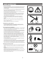
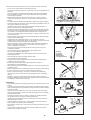
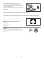
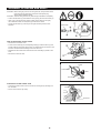
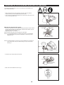
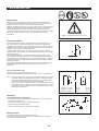
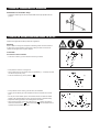
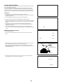
I Petunjuk Penggunaan Tài liệu hướng dẫn คูมือการใชงาน Important: Read this instruction manual carefully before putting the brush cutter/string trimmer into operation and strictly observe the safety regulations! Preserve instruction manual carefully! Penting: Bacalah petunjuk penggunaan ini dengan teliti sebelum mengoperasikan pemotong semak/mesin pemangkas bermata senar ini dan patuhilah dengan ketat peraturan keselamatan yang berlaku! Simpanlah buku petunjuk penggunaan ini dengan baik! Quan trọng: Đọc kỹ tài liệu hướng dẫn này trước khi vận hành máy cắt cỏ chạy xăng/máy tỉa cành giật dây chạy xăng và tuân thủ nghiêm ngặt các quy định về an toàn! Giữ tài liệu hướng dẫn một cách cẩn thận! ข้อสำคัญ: อ่านคู่มือการใช้งานนี้อย่างระมัดระวังก่อนใช้งานเครื่องตัดหญ้า/เครื่องเล็มหญ้าตัดขอบ และปฏิบัติตามกฎความปลอดภัยอย่างเคร่งครัด! เก็บคู่มือการใช้งานไว้ในที่ปลอดภัย! EM2500U English (Original instructions) Thank you very much for purchasing the MAKITA brush cutter/string trimmer. We are pleased to recommend to you the MAKITA brush cutter/string trimmer which is the result of a long development program and many years of knowledge and experience. Please read this booklet which refers in detail to the various points that will demonstrate its outstanding performance. This will assist you to obtain the best possible result from your MAKITA brush cutter/string trimmer. Table of Contents Page Symbols .........................................................................2 Safety instructions .........................................................3 Technical data................................................................7 Designation of parts.......................................................8 Assembly of engine and shaft .......................................9 Mounting of handle ......................................................10 Mounting of protector................................................... 11 Mounting of cutter blade or nylon cutting head............12 Fuels/Refuelling ...........................................................13 Correct handling of machine........................................14 Points in operation and how to stop ............................14 Resharpening the cutting tool ......................................15 Servicing instructions...................................................17 Storage ........................................................................19 SYMBOLS You will note the following symbols when reading the instructions manual. Wear eye and ear protection (for string trimmer only) Read instruction Manual Wear protective helmet, eye and ear protection (for brush cutter only) Take Particular care and Attention Forbidden Do not use metal blades (for string trimmer only) Keep distance Top permissible tool speed Flying object hazard Fuel and oil mixture No Smoking Engine-Manual start No open flame Emergency stop Protective gloves must be worn First Aid Kickback Recycling Keep the area of operation clear of all persons and pets ON/START Wear sturdy boots with non-slip soles. Steel toed safety boots are recommended. OFF/STOP 2 SAFETY INSTRUCTIONS General Instructions – To ensure correct operation, user has to read this instruction manual to make himself familiar with the handling of the brush cutter/string trimmer. Users insufficiently informed will risk danger to themselves as well as others due to improper handling. – It is recommended only to lend the brush cutter/string trimmer to people who have proven to be experienced with brush cutter/string trimmers. Always hand over the instruction manual. – First users should ask the dealer for basic instructions to familiarize oneself with the handling of an engine powered cutter. – Children and young persons aged under 18 years must not be allowed to operate the brush cutter/string trimmer. Persons over the age of 16 years may however use the device for the purpose of being trained only whilst under supervision of a qualified trainer. – Use brush cutter/string trimmers with the utmost care and attention. – Operate the brush cutter/string trimmer only if you are in good physical condition. Perform all work calmly and carefully. The user has to accept liability for others. – Never use the brush cutter/string trimmer after consumption of alcohol or drugs, or if feeling tired or ill. – National regulation can restrict the use of the machine. Intended use of the machine – The brush cutter/string trimmer is only intended for cutter grass, weeds, bushes, undergrowth it should not be used for any other purpose such as Edging or hedge cutting as this may cause injury. Personal protective equipment – The clothing worn should be functional and appropriate, i.e. it should be tightfitting but not cause hindrance. Do not wear either jewelry or clothing which could become entangled with bushes or shrubs. – In order to avoid either head, eye, hand or foot injuries as well as to protect your hearing the following protective equipment and protective clothing must be used during operation of the brush cutter/string trimmer. – Always wear a helmet where there is a risk of falling objects. The protective helmet (1) is to be checked at regular intervals for damage and is to be replaced at the latest after 5 years. Use only approved protective helmets. – The visor (2) of the helmet (or alternatively goggles) protects the face from flying debris and stones. During operation of the brush cutter/string trimmer always wear goggles, or a visor to prevent eye injuries. – Wear adequate noise protection equipment to avoid hearing impairment (ear muffs (3), ear plugs etc.). – The work overalls (4) protect against flying stones and debris. We strongly recommend that the user wears work overalls. – Special gloves (5) made of thick leather are part of the prescribed equipment and must always be worn during operation of the brush cutter/string trimmer. – When using the brush cutter/string trimmer, always wear sturdy shoes (6) with a non-slip sole. This protects against injuries and ensures a good footing. Starting up the brush cutter Diagrammatic figure – Please make sure that there are no children or other people within a working range of 15 meters (50 ft), also pay attention to any animals in the working vicinity. – Before use always check that the brush cutter/string trimmer is safe for operation: Check the security of the cutting tool, the control lever for easy action and check for proper functioning of the control lever lock. – Rotation of the cutting tool during idling speed is not allowed. Check with your dealer for adjustment if in doubt. Check for clean and dry handles and test the function of the start/stop switch. 3 15 Meters Start the brush cutter/string trimmer only in accordance with the instructions. – Do not use any other methods for starting the engine! – Use the brush cutter/string trimmer and the tools only for such applications as specified. – Only start the brush cutter/string trimmer engine, after the entire assembly is done. Operation of the device is only permitted after all the appropriate accessories are attached! – Before starting make sure that the cutting tool has no contact with hard objects such as branches, stones etc. as the cutting tool will revolve when starting. – The engine is to be switched off immediately in case of any engine problems. – Should the cutting tool hit stones or other hard objects, immediately switch off the engine and inspect the cutting tool. – Inspect the cutting tool at short regular intervals for damage (detection of hairline cracks by means of tapping-noise test). – Operate the brush cutter/string trimmer only with the shoulder strap attached which is to be suitably adjusted before putting the brush cutter/string trimmer into operation. It is essential to adjust the shoulder strap according to the user’s size to prevent fatigue occurring during use. Never hold the cutter with one hand during use. – During operation always hold the brush cutter/string trimmer with both hands. Always ensure a safe footing. – Operate the brush cutter/string trimmer in such a manner as to avoid inhalation of the exhaust gases. Never run the engine in enclosed rooms (risk of gas poisoning). Carbon monoxide is an odorless gas. – Switch off the engine when resting and when leaving the brush cutter/string trimmer unattended, and place it in a safe location to prevent danger to others or damage to the machine. – Never put the hot brush cutter/string trimmer onto dry grass or onto any combustible materials. – The cutting tool has to be equipped with it’s appropriate guard. Never run the cutter without this guard! – All protective installations and guards supplied with the machine must be used during operation. – Never operate the engine with faulty exhaust muffler. – Shut off the engine during transport. – During transport over long distances the tool protection included with the equipment must always be used. – Ensure safe position of the brush cutter/string trimmer during car transportation to avoid fuel leakage. – When transporting the brush cutter/string trimmer, ensure that the fuel tank is completely empty. – When unloading the brush cutter/string trimmer from the truck, never drop the Engine to the ground or this may severely damage the fuel tank. – Except in case of emergency, never drop or cast the brush cutter/string trimmer to the ground or this may severely damage the brush cutter/string trimmer. – Remember to lift the entire equipment from the ground when moving the equipment. Dragging the fuel tank is highly dangerous and will cause damage and leakage of fuel, possibly causing fire. • Resting • Transport • Refuelling • Maintenance • Tool Replacement Refuelling – Shut off the engine during refuelling, keep away from open flames and do not smoke. – Avoid skin contact with mineral oil products. Do not inhale fuel vapor. Always wear protective gloves during refuelling. Change and clean protective clothing at regular intervals. – Take care not to spill either fuel or oil in order to prevent soil contamination (environmental protection). Clean the brush cutter/string trimmer immediately after fuel has been spilt. – Avoid any fuel contact with your clothing. Change your clothing instantly if fuel has been spilt on it (to prevent clothing catching fire). – Inspect the fuel cap at regular intervals making sure that it can be securely fastened and does not leak. – Carefully tighten the fuel tank cap. Change location to start the engine (at least 3 meters away from the place of refuelling). – Never refuel in closed rooms. Fuel vapors accumulate at ground lever (risk of explosions). – Only transport and store fuel in approved containers. Make sure the fuel stored is not accessible to children. 4 rs ete 3m Method of operation – Only use the brush cutter/string trimmer in good light and visibility. During the winter season beware of slippery or wet areas, ice and snow (risk of slipping). Always ensure a safe footing. – Never cut above waist height. – Never stand on a ladder and run the brush cutter/string trimmer. – Never climb up into trees to perform cutting operation with the brush cutter/ string trimmer. – Never work on unstable surfaces. – Remove sand, stones, nails etc. found within the working range. Foreign particles may damage the cutting tool and can cause dangerous kickbacks. – Before commencing cutting, the cutting tool must have reached full working speed. Kickback Caution: Kickback – When operating the brush cutter, uncontrolled kickback may occur. – This is particularly the case when attempting to cut within a blade segment between 12 and 2 o’clock. – Never apply the brush cutter within a segment between 12 and 2 o’clock. – Never apply this segment of the brush cutter blade to solids, such as bushes and trees, etc., having a diameter in excess of 3 cm or the brush cutter will be deflected at great force with the risk of injuries. Diagrammatic figure Kickback prevention To avoid kickbacks, observe the following: – Operation within a blade segment between 12 and 2 o’clock presents positive hazards, especially when using metal cutting tools. – Cutting operations within a blade segment between 11 and 12 o’clock, and between 2 and 5 o’clock, must only be performed by trained and experienced operators, and then only at their own risk. Easy cutting with almost no kickback is possible within a blade segment between 8 and 11 o’clock. Diagrammatic figure Cutting Tools Employ only the correct cutting tool for the job in hand. EM2500U with cutter blade (Star Blade (4 teeth), Eddy Blade (8 teeth)) or Nylon cutting head. For cutting thick materials, such as weed, high grass, bushes, shrubs, underwood, thicket etc. (max. 2 cm dia. thickness). Perform this cutting work by swinging the brush cutter evenly in half-circles from right to left (similar to using a scythe). Maintenance instructions – The condition of the cutter, in particular of the cutting tool of the protective devices and also of the shoulder strap must be checked before commencing work. Particular attention is to be paid to the cutting blades which must be correctly sharpened. – Turn off the engine and remove spark plug connector when replacing or sharpening cutting tools, and also when cleaning the cutter or cutting tool. 5 Never straighten or weld damaged cutting tools. – Operate the brush cutter/string trimmer with as little noise and contamination as possible. In particular check the correct setting of the carburetor. – Clean the brush cutter/string trimmer at regular intervals and check that all screws and nuts are well tightened. – Never service or store the brush cutter/string trimmer in the vicinity of naked flames. – Always store the brush cutter/string trimmer in locked rooms and with an emptied fuel tank. Observe the relevant accident prevention instructions issued by the relevant trade associations and by the insurance companies. Do not perform any modifications on the brush cutter/string trimmer as this will endanger your safety. The performance of maintenance or repair work by the user is limited to those activities as described in the instruction manual. All other work is to be done by an Authorized Service Agent. Use only genuine spare parts and accessories released and supplied by MAKITA. Use of non-approved accessories and tools means increased risk of accidents. MAKITA will not accept any liability for accidents or damage caused by the use of non-approved cutting tools and fixing devices of cutting tools, or accessories. First Aid In case of accident make sure that a first-aid box is available in the vicinity of the cutting operations. Immediately replace any item taken from the first aid box. When asking for help, please give the following information: – Place of accident – What happened – Number of injured persons – Kind of injuries – Your name Packaging The MAKITA brush cutter/string trimmer will be delivered in two protective cardboard boxes to prevent transport damage. Cardboard is a basic raw material and is therefore consequently reusable or suitable for recycling (waste paper recycling). 6 TECHNICAL DATA EM2500U M Dimensions: length x width x height (without cutting blade) Mass (without plastic guard and cutting blade) EM2500U U handle mm kg 4.5 L 0.5 3 24.5 Volume (fuel tank) Engine displacement 1,770 * 620 * cm Maximum engine performance 0.73 at 7,000 min-1 kw Engine speed at recommended max. spindle speed min-1 8,800 Maximum spindle speed (corresponding) min-1 6,500 Maximum fuel consumption kg/h — g/kwh — Maximum specific fuel consumption min -1 3,000 Clutch engagement speed min -1 4,100 Carburetor type WALBRO WYJ Ignition system type Solid state ignition Spark plug type NGK BPMR7A Electrode gap mm 0.6 - 0.7 Idling speed Vibration per ISO 22867 Right handle (Rear grip) Left handle (Front grip) ahv eq Uncertainty K ahv eq 2 5.188 2 1.5 2 4.166 2 m/s m/s m/s Uncertainty K m/s 1.5 Sound pressure level average to ISO 22868 LPA eq dBA 97.5 Uncertainty K dBA 3 Sound power level average to ISO 22868 LWA eq dBA 107.25 Uncertainty K dBA 2.42 Mixed gas (gasoline: Makita Genuine Two-stroke Engine Oil = 50:1) Fuel Gear ratio 14/19 7 DESIGNATION OF PARTS EM2500U U Handle Type (4) (12) (4) (12) (9) (11) (9) (7) (11) (8) (7) (8) (13) (10) (16) (10) (15) (16) (15) (14) (13) (17) (14) (18) (3) (7) (19) G 1 (21) (1) (5) (22) (6) (20) (23) (2) 8 DESIGNATION OF PARTS Fuel Tank 2 Rewind Starter 3 Air Cleaner 4 I-O Switch (on/off) 5 Spark Plug 6 Exhaust Muffler 7 Clutch Case 8 Waist Pad 9 Hanger 10 Handle 11 Control Lever 12 Control Cable 13 Shaft 14 Protector (Cutting tool guard) 15 Gear Case 16 Handle Holder 17 Cutter Blade 18 Nylon Cutting Head 19 Fuel Filler Cap 20 Starter Knob 21 Primer Pump 22 Choke Lever 23 Exhaust Pipe ASSEMBLY OF ENGINE AND SHAFT CAUTION: Before doing any work on the string trimmer, always switch off the motor and pull the spark plug connector off the spark plug. Always wear protective gloves. CAUTION: Start the string trimmer only after having assembled it completely. – Loosen the two bolts (1) and insert the main pipe (2) into the case clutch (3). – Insert it up to the arrow-mark position. (Refer to the sketch on the right.) If it is difficult to insert, turn the spline (4) a little and re-insert. – Tighten the two bolts (1) uniformly on the right and left by Allen wrench supplied. Arrow-mark How to mount the control cable – Remove the air cleaner cover. – Put the control cable (5) into the adjusting cable (6). Shift the swivel (7) and put the cable into the swivel. At this time, be careful that the round hole in the swivel is oriented toward the fitting at the inner wire end. – Release the swivel and make sure that the inner wire fitting is placed in the hole. – Mount the air cleaner cover. Swivel Control cable Insert Round hole End fitting Connection of the switch cord – Connect the switch cords to the two cords from the engine by inserting one into the other. – Fix the cord connector by clamp. Connector 9 MOUNTING OF HANDLE CAUTION: Before doing any work on the brush cutter, always stop the engine and pull the spark plug connector off the spark plug. Always wear protective gloves! CAUTION: Start the brush cutter only after having assembled it completely. For machines with U Handle models – Place the handle-fixing metal so that the handle with the control lever will be positioned on the right (the right-hand grip side) as viewed from the engine side, and the other handle on the left side. – Fit the groove of the handle-fixing material to the handle end. Fix provisionally the attached metal by hexagon socket bolt supplied. – Adjust the handle to an easy-to-operate position, and tighten securely the four hexagon socket bolts uniformly on the right and left by Allen wrench. L R – Surround the throttle cable (1) which comes from carburetor along the engine cylinder cover in accordance with the direction which is away from the operator, and wrap it by waist pad (2) along the opposite side of the pipe operator. (2) (1) – Insert the throttle cable (1) of control lever into the clamping slot (3) of lower splint of handle holder. (1) (3) CAUTION: After waist pad is packed, the redundant throttle cable close to the engine side can not be curved which can cause phenomenon of too high idle speed and the blade can not stop, see right photo. 10 MOUNTING OF PROTECTOR To meet the applicable safety provisions, only the tool/protector combinations as indicated in the table must be used. Be sure to use genuine MAKITA cutter blades or nylon cutting head. – The cutter blade must be well polished, free of cracks or breakage. If the cutter blade hits against a stone during operation, stop the engine and check the blade immediately. – Polish or replace the cutter blade every three hours of operation. – If the nylon cutting head hits against a stone during operation, stop the engine and check the nylon cutting head immediately. Star Blade Eddy Blade Protector for metal blades Nylon cutting head Protector for cord cutter CAUTION: The appropriate protector must always be installed, for your own safety and in order to comply with accident-prevention regulations. Operation of the equipment without the guard being in place is not permitted. – Fix the protector (1) to the clamp (3) with two bolts M6 x 30 (2). (2) (3) (1) – When using the string head, fit the protector (6) into the protector (1), and tighten them with two nuts (5) and two screws (4). (4) (1) (6) (5) 11 MOUNTING OF CUTTER BLADE OR NYLON CUTTING HEAD Turn the machine upside down, and you can replace the cutter blade or the nylon cutting head easily. – Insert the hex wrench through the hole in the gear case and rotate the receiver washer (3) until it is locked with the hex wrench. (2) (1) – Loosen the nut (1) (left-hand thread) with the socket wrench and remove the nut (1), and clamp washer (2). (3) With the hex wrench still in place. – Mount the cutter blade onto the shaft so that the guide of the receiver washer (3) fits in the arbor hole in the cutter blade. Install the clamp washer (2) and secure the cutter blade with the nut (1). [Tightening torque: 13 - 23 N-m] Loosen Tighten NOTE: Always wear gloves when handling the cutter blade. NOTE: The cutter blade-fastening nut (with spring washer) is a consumable part. If there appears any wear or deformation on the spring washer, replace the nut. Hex wrench NOTE: The clamp washer (2), and nut (1) are not necessary for mounting the nylon cutting head. The nylon head should go on top of the receiver washer (3). – Screw the nylon cutting head onto the shaft. Tighten Loosen Hex wrench – Make sure that the blade is the left way up. Rotation 12 FUELS/REFUELLING Handling fuel Utmost care is required when handling fuel. Fuel may contain substances similar to solvents. Refuel either in a well ventilated room or outdoors. Do not inhale fuel vapors, avoid any contact of fuel or oil with your skin. Mineral oil products degrease your skin. If your skin comes in contact with these substances repeatedly and for an extended period of time, it will desiccate. Various skin diseases may result. In addition, allergic reactions may occur. Eyes can be irritated by contact with oil. If oil comes into your eyes, immediately wash them with clear water. If your eyes are still irritated, see a doctor immediately. Observe the Safety Instructions on page 4. Fuel and oil mixture The engine of the brush cutter is a high-efficiency two-stroke engine. It is run with a mixture of fuel and two-stroke engine oil. The engine is designed for unleaded regular fuel with a min. octane value of 91 RON. In case no such fuel is available, you can use fuel with a higher octane value. This will not affect the engine, but may cause poor operating behavior. A similar situation will arise from the use of leaded fuel. To obtain optimum engine operation and to protect your health and the environment, only unleaded fuel should be used! For lubricating the engine use a two-stroke engine oil (quality grade: TC-3), which is added to the fuel. The engine has been designed to use specified twostroke engine oil at mixture ratio of 50:1 to protect the environment. In addition, a long service life and a reliable operation with a minimum emission of exhaust gases is guaranteed. It is absolutely essential to observe a mixture ratio of 50:1 (specified 2-stroke engine oil), as otherwise reliable function of the brush cutter cannot be guaranteed. The correct mixture ratio: Gasoline Gasoline: Specified two-stroke engine oil = 50:1 or Gasoline: Other manufacturer’s two-stroke engine oil = 25:1 recommended Note: For preparing the fuel-oil mixture first mix the entire oil quantity with half of the fuel required, then add the remaining fuel. Thoroughly shake the mixture before filling it into the brush cutter tank. It is not wise to add more engine oil than specified to ensure safe operation. This will only result in a higher production of combustion residues which will pollute the environment and clog the exhaust channel in the cylinder as well as the muffler. In addition, the fuel consumption will rise and the performance will decrease. 50:1 25:1 + 1,000 cm3 (1 liter) 5,000 cm3 (5 liter) 10,000 cm3 (10 liter) 20 cm3 100 cm3 200 cm3 40 cm3 200 cm3 400 cm3 Refuelling The engine must be switched off. – Thoroughly clean the area around the fuel filler cap (2), to prevent dirt from getting into the fuel tank (1). – Unscrew the fuel filler cap (2) and fill the tank with fuel. – Tightly screw on the fuel filler cap (2). – Clean screw fuel filler cap (2) and tank after refuelling. (2) (1) Storage of Fuel Fuel cannot be stored for an unlimited period of time. Purchase only the quantity required for a 4 week operating period. Only use approved fuel storage containers. 13 CORRECT HANDLING OF MACHINE Attachment of shoulder strap – Adjust the strap length so that the cutter blade will be kept parallel with the ground. POINTS IN OPERATION AND HOW TO STOP Observe the applicable accident prevention regulations. Starting Move at least 3 m away from the place of refuelling. Place the brush cutter on a clean piece of ground taking care that the cutting tool does not come into contact with the ground or any other objects. Cold start (1) For machine with U Handle – Push the I-O switch (1) in the direction shown by the arrow. – First place the machine on the ground. – Give a gentle push on the primer pump (2) repeatedly (7 – 10 times) until fuel comes into the primer pump. – Push the choke lever (3) to the position “ ”. (3) (2) – Firmly hold the clutch case by your left hand, as illustrated. – Slowly pull the starter grip until resistance is felt and continue with a smart pull. – Do not pull out the starter rope to its full extent and do not allow the starter handle to be retracted without control, but ensure that it is retracted slowly. – Repeat the starting operation until initial ignitions are heard. – When the engine start, return the choke lever to “ ”. Please note that the choke lever will return to “ ” position automatically when the throttle lever is operated and the throttle is opened. 14 – Run the engine for approximately one minute at a moderate speed before applying full throttle. Note: – If the starter handle is pulled repeatedly when the choke lever remains at “ ” position, the engine will not start easily due to excessive fuel intake. – In case of excessive fuel intake, remove the spark plug and pull the starter handle slowly to remove excess fuel. Also, dry the electrode section of the spark plug. Caution during operation: If the throttle lever is opened fully in a no-load operation, the engine rotation is increased to 10,000 min-1 or more. Never operate the engine at a higher speed than required and at an approximate speed of 6,000 - 8,000 min-1. Starting the warm engine – Same as above, except without moving the choke lever (choke lever remains in the position “ ”). STOPPING – Release the throttle lever (4) fully, and when the engine rpm has lowered, push the I-O switch (1) to “O” position the engine will now stop. (1) – Be aware that the cutting head may not stop immediately and allow it to slow down fully. (4) ADJUSTMENT OF LOW-SPEED ROTATION (IDLING) The cutter blade or the nylon cutting head should not run when the control lever is fully released. If necessary, adjust the idle rpm using the idle adjusting screw. Checking the Idling speed – Idle speed should be set to 3,000 min-1. If necessary correct it by means of the idle screw (the blade or the nylon cutting head must not turn when the engine is on idle). Screwing in the screw (1) will cause an increase in the engine speed, whereas backing off the screw will reduce the engine speed. (1) Slow RESHARPENING THE CUTTING TOOL CAUTION: The cutting tools mentioned below must only be resharpened by an authorized facility. Manual resharpening will result in imbalances of the cutting tool causing vibrations and damage to the equipment. – cutter blade (star blade (4 teeth), eddy blade (8 teeth)) An expert resharpening and balancing service is provided by Authorized Service Agents. NOTE: To increase the service life of the cutter blade (star blade, eddy blade) it may be turned over once, until both cutting edges have become blunt. 15 High NYLON CUTTING HEAD Most effective cutting area The nylon cutting head is a dual string trimmer head capable of both automatic and bump & feed mechanisms. The nylon cutting head will automatically feed out the proper length of nylon cord by the changes in centrifugal force caused by increasing or decreasing rpms. However, to cut soft grass more efficiently, bump the nylon cutting head against the ground to feed out extra cord as indicated under operation section. Operation – Increase the nylon cutting head speed to approx. 6,000 min-1. Low speed (under 4,800 min-1) is not suitable, the nylon cord will not feed out properly at low speed. – The most effective cutting area is shown by the shaded area. Idle speed If the nylon cord does not feed out automatically proceed as follows: 1. Release the throttle lever to run the engine idle and then squeeze the throttle lever fully. Repeat this procedure until the nylon cord feeds out to the proper length. 2. If the nylon cord is too short to feed out automatically with the above procedure, bump the knob of the nylon cutting head against the ground to feed out the nylon cord. 3. If the nylon cord does not feed out with procedure 2, rewind/replace the nylon cord by following the procedures described under “Replacing the nylon cord”. Full speed Knob Replacing the nylon cord – First, stop the engine. – Press on the housing latches inward to lift off the cover, then remove the spool. Cover Latches Press – Hook the new nylon cord into the each hole at the spool, with one end of the cord extending about 80 mm (3-1/8”) more than the other. Then wind both ends firmly around the spool in the direction of the head rotation (left-hand direction indicated by LH and right-hand direction by RH on the side of the spool). Spool Press 80 mm (3-1/8”) For left hand rotation Spool – Wind all but about 150 mm (6”) of the cords, leaving the ends temporarily hooked through a notch on the side of the spool. 150 mm (6”) Notches 16 – Feed the cords through the eyelets to come out of the housing. Mount the spool in the housing with the spring and washer. Eyelets – Align the protrusion on the underside of the cover with the slots of the eyelets. Then push cover firmly onto the housing to secure it. Cover Protrusion Slot of eyelet SERVICING INSTRUCTIONS CAUTION: Before doing any work on the brush cutter, always switch off the motor and pull the plug cap off the spark plug (see “Checking the spark plug”). Always wear protective gloves. CAUTION: Never remove the recoil starter for yourself, which may cause an accident. It should be asked to the Authorized Service Agent. To ensure a long service life and to avoid any damage to the equipment, the following servicing operations should be performed at regular intervals. Daily checkup and maintenance – Before operation, check the machine for loose screws or missing parts. Pay particular attention to the tightness of the cutter blade or nylon cutting head. – Before operation, always check for clogging of the cooling air passage and the cylinder fins. Clean them if necessary. – Perform the following work daily after use: • Clean the brush cutter externally and inspect for damage. • Clean the air filter. When working under extremely dusty conditions, clean the filter the several times a day. • Check the blade or the nylon cutting head for damage and make sure it is firmly mounted. • Check that there is sufficient difference between idling and engagement speed to ensure that the cutting tool is at a standstill while the engine is idling (if necessary, reduce idling speed). If under idling conditions the tool should still continue to run, consult your nearest Authorized Service Agent. – Check the functioning of the I-O switch, the lock-off lever, the control lever, and the look button. Cleaning of air cleaner – Unscrew screw (1). – Remove the air cleaner cover (3). – Take out the sponge element (2), wash it in lukewarm water and dry it completely. – After cleaning, put back the air cleaner cover (3) and fasten it with screw (1). (1) NOTE: If there is excessive dust or dirt adhering to the air cleaner, clean it every day. A clogged air cleaner may make it difficult or impossible to start the engine or increase the engine rotational speed. (2) (3) 17 Checking the spark plug – Only use the supplied universal wrench to remove or to install the spark plug. – The gap between the two electrodes of the spark plug should be 0.6 – 0.7 mm (0.024” – 0.028”). If the gap is too wide or too narrow, adjust it. If the spark plug is clogged with carton or fouled, clean it thoroughly or replace it. CAUTION: Never touch the spark plug connector while the engine is running (danger of high voltage electric shock). 0.6 mm – 0.7 mm (0.024” – 0.028”) Supply of grease to gear case Grease hole – Supply grease (Shell Alvania 3 or equivalent) to the gear case through the grease hole every 30 hours. (Genuine MAKITA grease may be purchased from your MAKITA dealer.) Suction head in the fuel tank – The fuel filler (4) of the suction head is used to filler the fuel required by the carburetor. (4) – A periodical visual inspection of the fuel filter is to be conducted. For that purpose open the tank cap, use a wire hook and pull out the suction head through the tank opening. Filters found to have hardened, been polluted or clogged up are to be replaced. – Insufficient fuel supply can result in the admissible maximum speed being exceeded. It is therefore important to replace the fuel filter at least quarterly to ensure satisfactory fuel supply to the carburetor. Cleaning of muffler exhaust port – Check of muffler exhaust port (5) regularly. – If it is clogged by carbon deposits, carefully scratch the deposits out with a suitable tool. (5) Any maintenance of adjustment work that is not included and described in this manual is only to be performed by Authorized Service Agents. 18 STORAGE – When the machine is in storage for a long time, drain fuel from the fuel tank and carburetor, as follows: Drain all fuel from the fuel tank. Dispose of properly and in accordance with all local laws. – Remove the spark plug and a few drops of oil into the spark plug hole. Then, pull the starter gently, so that oil covers the engine inside and tighten the spark plug. Drain fuel Humidity – Clear dirt or dust from the cutter blade and outside of engine, wipe them with a oil-immersed cloth and keep the machine in a place as dry as possible. Maintenance schedule General Engine assembly, screws and nuts Visual inspection for damage and tightness Check for general condition and security After each refuelling Control lever I-O switch Functional check Functional check Daily Air filter Cooling air duct Cutting tool Idling speed To be cleaned To be cleaned Check for damage and sharpness Inspection (cutting tool must not move) Weekly Spark plug Muffler Inspection, replace if necessary Check and if necessary clean the opening Quarterly Suction head Fuel tank To be replaced To be cleaned Shutting down procedure Fuel tank Carburetor Empty fuel tank Operate until engine runs out of fuel Fault location F Engine not starting or with difficulty System Observation Cause Ignition system Ignition spark O.K. Fault in fuel supply or compression system, mechanical defect No ignition spark I-O switch operated, wiring fault or short circuit, spark plug or connector defective, ignition module faulty Fuel supply Fuel tank filled Incorrect choke position, carburetor defective, fuel supply line bent or blocked, fuel dirty Compression No compression when pulled over Cylinder bottom gasket defective, crankshaft seals damaged, cylinder or piston rings defective or improper sealing of spark plug Mechanical fault Starter not engaging Broken starter spring, broken parts inside of the engine Tank filled ignition spark existing Carburetor contaminated, must be cleaned Tank filled Incorrect idling adjustment, carburetor contaminated Warm start problems Engine starts but dies Fuel supply Fuel tank vent defective, fuel supply line interrupted, cable or I-O switch faulty Insufficient performance Several systems may simultaneously be affected Engine idling poor 19 Air filter contaminated, carburetor contaminated, muffler clogged, exhaust duct in the cylinder clogged Makita Corporation Anjo, Aichi, Japan EM2500U-SEA4-1012 ALA www.makita.com