1
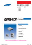
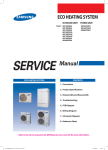
SYSTEM AIR CONDITIONER
OUTDOOR UNIT
AM036FXMDCH
AM048FXMDCH
AM053FXMDCH
AIR CONDITIONER
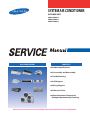
CONTENTS
C Product Specifications
C Disassembly and Reassembly
C Troubleshooting
C PCB Diagram
C Wiring Diagram
C Reference Sheet
C Check Operation & Amount of
Refregent Automatically Checking
Refer to the service manual in the GSPN(see the rear cover) for the more information.
Contents
͑غProduct Specifications
...............................................................................................................
1
1. The Feature of Product........................................................................................................................
1
1-1 Featres ...........................................................................................................................
1
2. Product Specifications .........................................................................................................................
7
1͑غDisassembly and Reassembly ............................................................................................... 8
1 غTroubleshooting ............................................................................................................................ 18
1. Error Display .......................................................................................................................................... 18
2. Error Code .............................................................................................................................................. 19
3. How to take measures for each symptom ....................................................................................... 20
3-1 Communicaion error between indoor and outdoor units during tracking(Error Code:E201) .......
3-2 Communicaion error between indoor and outdoor units during tracking(Error Code:E202) .......
3-3 Communicaion error (1minute)between Main and Sub Micoms of an Outdoor unit or among
Outdoor Units (Error Code:E203) .......................................................................................
3-4 Outdoor temperature sensor error (Error Code : E221, E231, E251, E269) .................................
3-5 High pressure temperature sensor error (Open/Short) (Error Code : E291)
Low pressure temperature sensor error (Open/Short) (Error Code : E296) ......
20
21
3-6 Compressor down by antifreeze control (Error Code: E403) ...................................................
3-7 Comp. down due to a protective control of high pressure (Error Code : E407) ..........................
3-8 Comp. down due to a protective control of low pressureError Code : E410) .............................
3-9 Comp. down due to a discharge temperature sensor of a compressor (Error Code : E416)..........
3-10 Reverse phase detection error (3Phase outdoor unit) (Error Code : E425) ...............................
3-11 ESC EEV open error (Error Code : E438) ..............................................................................
3-12 Refrigerant leakage error (Error Code : E439) ......................................................................
3-13 Prohibition of the compressor operation due to outdoor temperature (Error Code : E440, 441).....
3-14 Refrigerant leakage error (during operation) (Error Code : E443) ..............................................
3-15 Outdoor unit fan error (Error Code : E458, 475) .....................................................................
3-16 Comp down due to OLP temperature control (Error Code : E463) ............................................
3-17 Compressor starting/rotation error (Error Code : E461, E467) ..................................................
3-18 Current error / PFC overload error (Error Code : E462, E484) ....................................................
3-19 IPM over current error (Error Code : E464) ..........................................................................
3-20 DC-Link voltage under/over error (Error Code : E466) ..........................................................
3-21 Gas leak error (Error Code : E554)......................................................................................
3-22 Others ..........................................................................................................................
25
26
27
28
29
30
31
32
32
33
34
35
37
38
41
43
45
22
23
24
1 غPCB Diagram .....................................................................................................................................
46
1 غWiring Diagram
..............................................................................................................................
52
1 غReference Sheet ..............................................................................................................................
53
1. Refrigerant cycle diagram...................................................................................................................
2. Nomenclature ......................................................................................................................................
53
54
1 غCheck Operation & Amount of Refrigerant Automatically Checking .......
55
1. Check Operation...................................................................................................................................
55
1-1 Check Operation .............................................................................................................
1-2 How to trouble of the "Undetermined" ...............................................................................
1-3 Automatic Commissioning Error Code ................................................................................
2. Amount of Refrigerant Automatically Checking
...........................................................................
55
56
63
64
͑غProduct Specifications
1. The Feature of Product
1-1 Feature
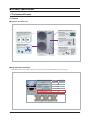
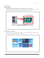
QStructure of outdoor unit
Anti-chloride coated outdoor unit
heat exchanger
High performance BLDC fan motor
䭓Anti-corrosion /erosion G-Fin
provide stable heat exchanging
performanceation
䭓33% more efficient compare to AC motor
䭓Wide speed control range, less noise
generation
Turbo Inter-cooler
䭓Long piping up to 175m with sub-cooling
䭓Up to 50m levela difference is allowed for
installation
High efficient propeller fan
Cross section of a Turbo Inter-cooler
䭓Reduced noise on outdoor
unit
䭓Improved heat exchange
rate
Twin BLDC compressor
䭓Increased energy efficiency
compare to conventional compressor
䭓Stable operation with 80%
decreased vibration
QHigh efficient heat exchanger
High efficient G-Fin & epoxy acrylic coating has increased heat transfer and hydrophilicity on heat exchanger.
Company A
Diameter
Ø8
Heat transfer surface area
Condensation
ᇉ
10.3%
ᇉ
30.8%
Internal heat transfer performance
Company A
2
19%
Evaporation
ᇉ
Pressure
loss in heat
exchanger
Ø7
Pressure resistance
14.1%
Same
Samsung Electronics
Product Specifications
Feature (cont.)
QApplication of wide fin
0.24
Ø7 Groove
12
Ø8 High Groove
Increased by 30.8%
0.16
Decreased by 14%
0.12
10
8
0.08
4
0.04
2
0.00
20
30
40
Refrigerant flow (Kg/h)
New Ø7 wide fin
New Ø8 wide fin
Heat transfer
amount
Heat transfer
amount
15%
15%
Ø7 wide fin
Pressure loss (kPa/m)
Amount of transferred heat (kW/m)
High efficient heat exchanger has been applied, therefore it delays the onset of frost formation and increased heat transfer efficiency.
0
Ø8 Fin
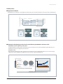
QOptimized cooling/heating and increased system efficiency! Liquid EEV & Turbo Inter-cooler
• Liquid EEV for increased efficiency of the system
Through Liquid EEV, controlling of valve opening has become more efficient and it achieved optimized system efficssiency and
minimized noise from the refrigerant in the indoor unit.
• Turbo Inter-cooler
High performing shell & tube type heat exchanger has been applied to secure cooling/heating efficiency. It has secured enough
subcooling to acquire reliability on long piping and it also increased cooling/heating efficiency.
Saturated liquid refrigerant
Temperature
Low temperature
gas refrigerant
온도
Low temperature
liquid refrigerant
Sub-cooled
liquid refrigerant
Cross section of the
Turbo inter-cooler
Cross section of the
conventional inter-cooler
*Increased heat transfer area with Shell & Tube type
Turbo Inter-cooler
Samsung Electronics
3
Product Specifications
Feature (cont.)
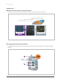
QReinforced corrosion resistance on the heat exchanger
To prevent corrosion of the products which is installed in saline area, corrosion resistance has been reinforced.
Hydrophilic layer (Acrylic resin + surfactant)
Anti corrosive layer (Epoxy acrylic)
Raw aluminum material
0.3 m
2.0 m
92 m
Company A
No corrosion after 1,000 hours of test
Corrosion is evident after 1,000 hours of test
Company A
* Tested by Samsung
QLong piping/High level difference technology
Longest piping length is allowed up to 175m (equivalent length) and Maximum 50m of level difference is allowed for more flexible
installation.
Long piping
175m
(Equivalent length)
Level
difference
High level
between
difference
50m indoor units
15m
4
Samsung Electronics
Product Specifications
Feature (cont.)
QMemory module
• Achieves world-class efficiency with hyper compressor that applies double compression technology
If outdoor unit malfunction occurs, diagnose and repair of the problem will be much quicker with the last 3 minutes worth of a data
saved before the malfunction. (With the extra memory module, 3 months worth of a data can be saved.)
※ 3 month worth of data can be saved
when memory module is installed
Black box function of the Main PCS
QSilent operation at nighttime
• When outdoor unit needs to operate more silently during nighttime, silent mode can be set from the outdoor unit option mode.
• Silent mode can be adjusted in 3 levels depending on the level of noise.
Highest temperature
6 hours
12 hours of silent mode
Operation
time
7 : 00
Samsung Electronics
13 : 30
End
19 : 00
7 : 00
5
Product Specifications
Feature (cont.)
QRefrigerant pump-down
If you need to move/replace the outdoor unit or when there are problems on indoor units or on the pipes, outdoor unit will recover
refrigerant remaining on the pipes.
Indoor unit
malfunction
Refrigerant recoveringsss
QSystem check through View mode
• Through the window on outdoor unit PCB display, you can check the main system data during operation.
• Shortened maintaining and inspection
• Displaying 15 main data including high pressure of system
- Outdoor temperature
- Discharge temperature of the compressor
- Condensing temperature
• Using the DIP switch on the outdoor unit PCB, you can limit the running current of the system
6
Samsung Electronics
Product Specifications
Feature (cont.)
QMaximum 9 indoor unit connection
You may connect up to 9 indoor units on a single outdoor unit. It will allow more powerful and flexible air conditioning system
and you can select refrigerant pipe length, or number of indoor units depending on the needs for office, commercial and residential
places.
Maximum 9 indoor unit connection
QConvenient product installation
Service valve is not exposed to keep the neat appearance and pipe can be connected in 4 different directions which provide flexible
installation and maintenance services.
Conventional
* For models with 9kW or larger (Flare type connection)
Samsung Electronics
7
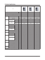
2. Product Specifications
Type
Performance
38,000
48,000
53,000
Model
Btu/h
AM036FXMDCH
AM048FXMDCH
AM053FXMDCH
Power Supply(Φ/V/Hz)
1, 208~230, 60
1, 208~230, 60
1, 208~230, 60
Mode
HP
HP
HP
Cooling
Btu/h
38,000
48,000
53,000
Heating
Btu/h
42,000
54,000
61,000
-10°C Heating
Btu/h
26,500
35,000
38,000
Cooling*
A
15.2
20.7
24.7
Heating*
A
18.1
23.2
26.6
Cooling*
W
3390
4700
5610
Heating*
W
4100
5270
6060
Performance
Running Current
Power
Input
Power Breaker(MCCB/ELB)
Compressor
A
4,100
5270
40
Type
-
Twin BLDC Inverter
Twin BLDC Inverter
Twin BLDC Inverter
Piston
cc/REV
43.0
43.0
43.0
Output
W
-
-
-
Type
-
POE
POE
POE
Charging
Lubricant
Refrigerant
FAN
cc
1,700
1,700
1,700
Type
-
R410A
R410A
R410A
Factory Charging
kg
3.2
3.2
3.3
Type
-
Propeller Fan
Propeller Fan
Propeller Fan
Motor Output
W
125x2
125x2
125x2
Airflow rate
CMM
95 (C) / 100 (H)
95 (C) / 100 (H)
95 (C) / 100 (H)
Liquid
ø,mm
9.52
9.52
9.52
Gas
ø,mm
15.88
15.88
19.05
Max. Length
M
300
300
300
Length
M
150
150
150
Max. Height
M
50
50
50
Piping connections
Pipe
Installation Limitation
Cable
Set Size
Operating
Temp. Range
Main Power(Below/about 20m)
mm
CV 2.5/4.0
CV 2.5/4.0
CV 4.0/6.0
Communication
mm
VCTF 0.75~1.5
VCTF 0.75~1.5
VCTF 0.75~1.5
Net weight
Kg
100
100
103
Shipping Weight
Kg
105
105
108
Net dimension(WxHxD)
mm
940x1,210x330
940x1,210x330
940x1,210x330
Shipping dimension(WxHxD)
mm
995x1,338x426
995x1,338x426
995x1,338x426
Cooling
°C
-5~48
-5~48
-5~48
Heating
°C
-20~26
-20~26
-20~26
6
8
9
Maximum of connected indoor units
* Rated Power/Current using Ducted indoor units
8
Samsung Electronics
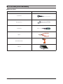
͑غDisassembly and Reassembly
QNecessary Tools
Item
Remark
+Screw Driver
Monkey Spanner
–Screw Driver
Nipper
Electric Motion Driver
L-Wrench
Samsung Electronics
9
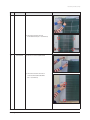
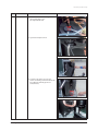
Disassembly and Reassembly
QOUTDOOR UNIT
No
Parts
1
Cabi Front RH
Procedure
Remark
You must turn off the Power before
disassembly.
1) Unscrew and remove 2 mounting screw in
the Cabinet Front RH. (Use + Screw Driver)
10
2
Cabi Top
3
Cabi Install Front
1) Unscrew and remove 9 screws
on each side of the Cabinet-Top.
(Use +Screw Driver)
1) Unscrew and remove 1 screw
in the Cabinet-Install Front.
(Use +Screw Driver)
Samsung Electronics
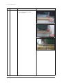
Disassembly and Reassembly
No
Parts
4
Guard Cond
Procedure
Remark
1) Pull the sensor from Guard Cond.
2) Unscrew and remove 4 screws
in the Guard Cond. (Use + Screw Driver)
5
Cabi Back RH
1) Pull the sensor from Cabi Back RH.
2) Unscrew and remove 4 screws on
each side of the Cabinet Back RH.
(Use + Screw Driver)
Samsung Electronics
11
Disassembly and Reassembly
12
No
Parts
6
Cabi Install Back
7
Cabi Front LF
Procedure
Remark
1) Unscrew and remove 1 screw
in the Cabinet-Install Back.
(Use +Screw Driver)
1) Unscrew and remove 10 screws
in the Cabinet-Front LF.
(Use +Screw Driver)
Samsung Electronics
Disassembly and Reassembly
No
Parts
8
Fan
Samsung Electronics
Procedure
Remark
1) Turn 2 mounting nuts as shown in the
picture and remove it. (Use L Wrench or
Monkey Spanner or Socket Wrench )
13
Disassembly and Reassembly
No
Parts
Procedure
9
Motor
1) Separate the Fan Propeller.
2) Unscrew and remove the 8 Motor mounting
screws. (Use +Screw Driver)
Remark
3) Disconnect the Motor wire from
Ass’y Control Out.
10
14
Bracket Motor
1) Unscrew and remove 2 mounting screws in
Bracket Motor. (Use + Screw Driver)
Samsung Electronics
Disassembly and Reassembly
No
Parts
11
Control Out
Procedure
Remark
1) Disconnect 9 Connectors from
Ass’y control Out.
2) Unscrew and remove 1 mounting screw in
Control Out. (Use + Screw Driver.)
3) Separate Ass’y Control Out.
Samsung Electronics
15
Disassembly and Reassembly
No
Parts
12
Ass'y Tube EEV
Procedure
Remark
1) Purge the Coolant first.
2) Separate 2 parts of the pipe using a welder.
When removing the compressor,
Heat Exchanger and Pipe, purge the
refrigerant inside the Compressor
completely and remove the pipe with
a welding flame.
13
Ass'y Tube Suction
14
Ass'y Tube 4Way
1) Separate 2 parts of the pipe using a welder.
1) Unscrew and remove 2 mounting screws
in Oil Separator. (Use + Screw Driver.)
2) Separate 2 parts of the pipe using a welder.
16
Samsung Electronics
Disassembly and Reassembly
No
Parts
13
Compressor
Procedure
Remark
1) Unscrew and remove 1 mounting
nut in bottom of the cover.
(Use Adjustable Wrench)
2) Separate the Compressor Felt.
3) As shown in the picture, unscrew and
remove 3 mounting screws from the bottom.
(Use L-Wrench or Monkey Spanner or
Socket Wrench)
Samsung Electronics
17
Disassembly and Reassembly
18
No
Parts
16
Cond Out
Procedure
Remark
1) Unscrew and remove 3 screws
on each side of the Ass’y Cond Out.
(Use + Screw Driver)
Samsung Electronics
͑غTroubleshooting
1. Error Display
Samsung Electronics
19
2. Error Code
20
No.
Code
Description
1
E201
Communication error between indoor and outdoor unit (Tracking failure or the setting quantity/address of indoor unit
in outdoor unit’s PCB differs from the quantity/address of installed indoor unit.)
2
E202
Communication error between indoor and outdoor unit. (All the indoor communication error, outdoor communication
cable error.)
3
E203
Communication error between main and sub micom or communication error between main and sub outdoor units.
4
E221
Error on ambient temperature sensor of outdoor unit. (Open or Short)
5
E251
Error on discharge temperature sensor of compressor. (Open or Short)
6
E231
Error on Cond-out temperature sensor of outdoor unit. (Open or Short)
7
E291
High pressure sensor error (Open/Short)
8
E296
Low pressure sensor error (Open/Short)
9
E308
Suction sensor error (Open/Short)
10
E311
Double tube sensor error (Open/Short)
11
E403
Antifreeze error
12
E407
Compressor stop by high pressure protection control
13
E410
Compressor stop by low pressure protection control
14
E416
Compressor stop by discharge temperature protection control
15
E419
EEV open error
16
E425
Reverse phase detection error
17
E438
EVI EEV open error
18
E439
Refrigerant leakage error (during stop status)
19
E440
Prohibition of heating operation when the ambient temperature is over 30°C
20
E441
Prohibition of cooling operation when the ambient temperature is below -15°C
21
E443
Refrigerant leakage error (during operation)
22
E458
Outdoor fan 1 error
23
E460
Power or voltage in connection wire between indoor-outdoor unit
24
E461
Compressor starting error
25
E462
Total current protection control, compressor stops
26
E463
OLP temperature control, compressor stops
27
E464
IPM over current error
28
E465
Compressor overload error
29
E466
DC-Link voltage under/over error
30
E467
Compressor rotation error
31
E468
Current sensor error
32
E469
DC LINK voltage sensor error
33
E470
EEPROM read/write error
34
E471
EEPROM unmatching error
35
E474
Heat sink temperature error
36
E475
Outdoor fan 2 error
37
E484
PFC overload
38
E485
Input current sensor error
39
E500
Heat sink overheat
40
E554
Gas leak error
Samsung Electronics
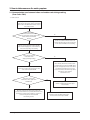
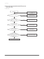
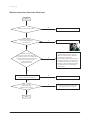
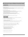
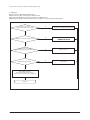
3. How to take measures for each symptom
3-1 Communication error between indoor and outdoor units during tracking
(Error Code : E201)
1. How to check
Compare the number of setting values of
setup switch for the number of indoor unit installed
for the outdoor unit PCB and the number of actual
indoor units installed.
Is the number of
actual indoor units installed and the
number of setting values of setup switch for the
number of indoor unit installed
identical?
No
Set the correct number of indoor units on the
outdoor unit switch and press the reset key (K3)
on the outdoor unit PCB to execute tracking.
Yes
Press the reset key (K3) of the outdoor unit PCB
then check the display part to see the number of
indoor units responding to the tracking
Is there any response from
indoor units on the
display part during tracking?
No
Yes
After 2 minutes, find an indoor unit that shows
a communication error then check if PCB address
setup has overlapped. (If an indoor unit’s address
is overlapped, communication error occurs)
- In that case, all indoor units with wrong address
setup for more than 2 will have
communication error.
Remove communication line from the
outdoor unit to indoor units then measure 2 lines
on the outdoor unit with SCOPE.
At that time, is the power
between the 2 lines a squire wave
with DC±0.7V?
No
If there is any problem with the address,
check the communication line then replace
indoor unit PCB.
Yes
Check the communication line from the outdoor unit
to indoor units and if there is no problem, find an indoor unit
that hampers communication by making a connection to
each unit and replace the indoor unit PCB
after checking out lines.
Samsung Electronics
Check the outdoor unit PCB communication
line and connector then replace the PCB.
21
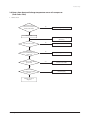
Troubleshooting
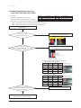
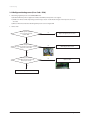
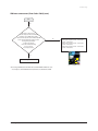
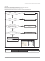
3-2 Communication error between indoor and outdoor units after completing tracking
(Error Code : E202)
1. How to check
Press the reset key (K3) of the outdoor unit PCB
then check the display part.
Is there any response from
indoor units on the
display part during tracking?
No
After 2 minutes, find an indoor unit than shows a
communication error then check if PCB address setup
has overlapped. (If an indoor unit's address is overlapped,
communication error occurs)
- In that case, all indoor units with wrong address
setup for more than 2 will have communication error.
Yes
Remove a communication line
from the outdoor unit to indoor units then
measure 2 lines on the
outdoor unit with SCOPE.
If there is any problem with the address, check the
communication line then replace indoor unit PCB.
At that time, is the power
between the 2 lines a square wave?
No
Yes
Check the outdoor unit PCB communication
line and connector then replace the PCB
Reconnect the communication line from the
outdoor unit to indoor units then remove all communication
connectors on the indoor unit PCB then find an indoor unit
that hampers communication by making a connection to
each unit and replace indoor unit PCB after checking out lines.
Good
Defective
0.7V
0.7V
22
Samsung Electronics
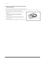
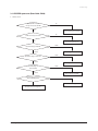
Troubleshooting
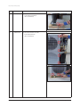
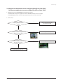
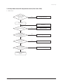
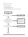
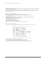
3-3 Communication error (1 minute) between Main and Sub Micoms of an Outdoor unit or
among Outdoor Units (Error Code : E203)
1. Check items
1) Is there power on outdoor unit inverter PBA?
2) Connect the power cable/check the fuse
3) Is there any problem on communication cable between outdoor unit inverter (CN31) <-> Main PBA (CN39)?
4) Check the communication cable connection
2. Check procedure
Turn off the power and turn it on again after 30 seconds.
Is there any communication error?
No
End service
Yes
Is there power on Inverter PBA?
No
Connect the power cable/check the fuse
1. Is there any problem on the power cable between
outdoor unit main l EMI PBA?
2. Is there any problem on the power cable between
outdoor unit inverter l EMI PBA?
[Check the LED on inverter PBA]
[Check list for AM666FXMDCH series]
Yes
Is there any problem on
communication cable between outdoor unit inverter
(CN31) l Main PBA (CN39)?
No
Check the communication cable connection
Yes
Change the outdoor unit inverter or main PBA
1. If the 7-segment on the outdoor unit main PBA shows E203
error, change the PBA o outdoor unit main PBA is normal
2. When the LED on the outdoor unit inverter is shown as
following; Red-On, Green-On, Orange-Blinking and if the
7-segment on the outdoor unit main PBA does not display
anything, change the main PBA o Outdoor unit inverter
PBA is normal
[7-segment on
Main PBA (Common)]
Samsung Electronics
[Check list for AM666FXMDCH series]
Inverter PBA connector (CN31)
MAIN PBA connector (CN39)
[AM666FXMDCH series
inverter PBA LED]
23
Troubleshooting
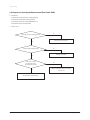
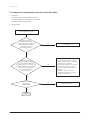
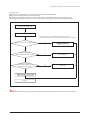
3-4 Outdoor temperature sensor error
(Error Code : E221, E231, E251, E269)
Error code
Error explanation
1. Check items
E221
Outdoor unit temperature sensor Error
1) Check the temperature sensor connector
E231
Outdoor unit COND.sensor Error
2) Check the resistance value of outdWoor temperature
E251
Outdoor unit discharge sensor Error
3) When E221 occurs, please recheck display two minutes later.
If E221 is displayed two minutes later, please follow the below check produre.
If E441 is displayed two minutes later, please follow E441 check produre.
2. Check procedure
Error code
Error explanation
E320
Indoor unit OLP sensor Error
E308
Suction temperature sensor error
E311
Double tube temperature sensor error
Turn off the power
Is the temperature sensor
connector properly connected?
No
Connect the temperature sensor connector
Check the CN43 connection
Check the CN44 connection
Yes
If the resistance value measure
on temperature sensor similar to the values on the
table on the right side?
Change the temperature sensor o Turn on the power
o Check if everything is normal and end service
No
OLP sensor: 200kΩ at 25°C
Discharge sensor: 200kΩ at 25°C
COND. sensor: 10kΩ at 25°C
Outdoor unit temperature sensor: 10kΩ at 25°C
OLP : 200Kohm at 25°C
D-tube : 10Kohm at 25°C
(Ex.) Resistance value for temperatures measured by Cond. Sensor/
outdoor temperature sensor : E231, E221
Yes
Current
Temp. (°C)
Resistance
(kΩ)
Current
Temp. (°C)
Resistance
(kΩ)
70
4
20
10
60
5
10
20
50
6
0
30
40
7
-10
40
30
8
Ex) Temperature 26°C –
Resistance 10.28kΩ
(Ex.) Resistance value for temperatures measured by OLP Sensor/
Discharge sensor: E320, E251
If the resistance value measure
on temperature sensor similar to the values on the
table on the right side?
No
Current
Temp. (°C)
Resistance
(kΩ)
Current
Temp. (°C)
Resistance
(kΩ)
80
40
30
180
70
50
20
220
60
60
10
320
50
90
0
550
40
110
Ex) Temperature 21°C –
Resistance 205.4kΩ
Check if everything is normal and end service
Yes
Change the outdoor unit PBA o Turn on the power o
Check if everything is normal and end service
24
Samsung Electronics
Troubleshooting
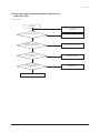
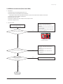
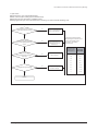
3-5 High pressure temperature sensor error (Open/Short) (Error Code : E291)
Low pressure temperature sensor error (Open/Short) (Error Code : E296)
1. High/low pressure sensor OPEN/SHORT error determination method
1) Identifies from when power is supplied or 2 minutes after RESET, and only when set is stopped.
2) An OPEN/SHORT error will occur if the input voltage standard exceeds 0.5V ~ 4.95V range
2. How to check
Did the high/low pressure
connector get disconnected from
the PCB?
No
Please re-inspect after connecting
the connector to the PCB
Yes
Is there refrigerant inside
the set? (Please check by connecting the manifold
gauge to the service valve)
No
Refill refrigerant after vacuum
Yes
On the high/low-pressure
sensor terminals of the PCB, is the value of voltage
5V, between pins 3 and 4?
No
Refill refrigerant after vacuum
Yes
The فmark is the 1st pin on the PCB.
Replace high/low-pressure sensor
Samsung Electronics
25
Troubleshooting
3-6 Compressor down by antifreeze control (Error Code: E403)
1. Check items
1) Check if the indoor fan/motor is working properly
2) Check if the indoor EEV is working properly
3) Check the indoor heat exchanger IN/OUT sensor
4) Check if the indoor air inlet blocked
2. How to check
Is the indoor fan/motor working properly?
No
Check the relevant indoor fan
Yes
Is the indoor EEV working properly?
No
Check the relevant EEV
Yes
Is the sensor on indoor
heat exchanger shows
the temperature correctly?
Yes
No
Refer to temperature sensor error section to
check for error
Check for indoor air inlet blockage
26
Samsung Electronics
Troubleshooting
3-7 Comp. down due to a protective control of high pressure
(Error Code : E407)
1. How to check
Test operation
Connect S-net and Manifold gauge
(Mandatory)
Are service valves open?
No
Open the service valve
Yes
Do the values of S-net and
Manifold gauge correspond?
No
Replace a high pressure sensor
Yes
Does indoor/outdoor EEV
operate well?
No
Check the relevant EEV
Yes
Is there any clogged place
in the piping (ex. filter)?
Yes
Check the piping
No
Check the amount of refrigerant
Samsung Electronics
27
Troubleshooting
3-8 Comp. down due to a protective control of low pressure
(Error Code : E410)
1. How to check
Test operation
Connect S-net and Manifold gauge
(Mandatory)
Are service valves open?
No
Open the service valve
Yes
Do the values of S-net and
Manifold gauge correspond?
No
Replace a high pressure sensor
Yes
Does indoor/outdoor EEV
operate well?
No
Check the relevant EEV
Yes
Is there any clogged place
in the piping (ex. filter)?
Yes
Check the piping
No
Is there any leakage
in liquid pipe valve or discharge
check valve of the stop-side outdoor unit when
several outdoor units are in
operation?
Yes
Replace the relevant components
No
Check the amount of refrigerant
28
Samsung Electronics
Troubleshooting
3-9 Comp. down due to a discharge temperature sensor of a compressor
(Error Code : E416)
1. How to check
Is the discharge sensor
resistance of the compressor
normal? (refer to E251)
No
Replace discharge temperature sensor
Yes
Test operation
Connect S-net and Manifold gauge
(Mandatory)
Are service valves open?
No
Open the service valve
예
Do the values
of S-net and Manifold gauge
correspond?
No
Replace a high pressure sensor
Yes
Does indoor/outdoor EEV
operate well?
Yes
Check the relevant EEV
No
Is there any
clogged place in the piping
(ex. filter)?
Check the piping
Check the amount of
refrigerant
Samsung Electronics
29
Troubleshooting
3-10 Reverse phase detection error (3Phase outdoor unit)
(Error Code : E425)
1. When power is on, it checks the power status used for 3-phase power compressor.
When the order of 3-phase L1(R) – L2(S) – L3(T) is changed (reversed) or there is a phase that does not receive power (phase fail),
it will display [E425] and the air conditioner will stop operating.
1) Check the voltage on L1(R) – L2(S) phase/ L1(R) – L3(T) phase/ L2(S) –
L3(T) phase.
2) When there is any terminal that does not have normal voltage,
check the external power of the air conditioner and take
appropriate measures.
3) If 3-phase power is normal check the phase of the power line using
3-phase tester. If it shows reverse phase, please change the current
3-phase tester
power line connection.
4) After completing above, press reset key (K3) then check the power again.
30
Samsung Electronics
Troubleshooting
3-11 ESC EEV open error (Error Code : E438)
1. How to check
Is the ESC EEV connector
correctly connected to the PBA?
No
Yes
Is EEV coil correctly connected?
Check and connect the connector
No
Yes
Check the leakage on ESC EEV
Check and assemble the coil
Failure
Normal
Check the leakage on sub-cooler
Change the ESC EEV
Failure
Normal
Check the leakage on
indoor unit EEV
Normal
Change the sub-cooler
Failure
Change the indoor unit EEV
Check the piping connection
Connect liquid-gas pipe)
Re-install the pipe
Check the amount of refrigerant
Samsung Electronics
31
Troubleshooting
3-12 Refrigerant leakage error (Error Code : E439)
1. Determining high/low-pressure sensor OPEN/SHORT error
1) Identifies from when power is supplied or 2 minutes after RESET, and only when set is stopped.
2) An E439 error will occur if the input voltage standard ranges of 0.5V ~ 4.95V of both the high- and low-pressure sensors are
exceeded.
3) Will occur if the measured value of both high/low-pressure sensors is 1kgf/cm2G
2. How to check
Did the high/low-pressure
connector get disconnected
from the PCB?
No
Replace the high/low-pressure sensor
Yes
Is there refrigerant inside
the set? (Please check by connecting the manifold
gauge to the service valve)
No
Refill refrigerant after vacuum
Yes
On the high-pressure sensor
of the PCB, is the value of voltage 5V,
between pins 3 and 4?
No
Replace the PCB
Yes
The فmark is the 1st pin on the PCB.
Replace the high/low-pressure sensor
32
Samsung Electronics
Troubleshooting
3-13 Prohibition of the compressor operation due to outdoor temperature
(Error Code : E440, 441)
1. How to check
The above error code is not caused by a product's problem but a function to protect the product by limiting the available temperature
range so please refer to the usable temperature range in the product manual.
If the error code is displayed despite a condition that does not belong to any of the above diagnosis methods, read the temperature
sensor value of the outdoor inlet air with View Mode or S-net, and if the actual outdoor temperature is different, please replace the
temperature sensor.
3-14 Refrigerant leakage error (during operation) (Error Code : E443)
1. How to check
Is high pressure sensor
correctly connected to PCB?
No
Check and reconnect the connector
Yes
Is there leakage of refrigerant
in the system or charging inferior?
(Check with manifold gauge)
No
Yes
Refill or recharge the refrigerant
Replace the high pressure sensor
Samsung Electronics
33
Troubleshooting
3-15 Outdoor unit fan error (Error Code : E458, 475)
1. Check items
1) Check the connection of the fan connector (CN90, CN 91)
2) Check the voltage of the fan motor connector on outdoor unit inverter PBA
3) Check the power connection on outdoor unit inverter PBA
4) Check the fan motor (Motor connector must be disconnected after 30 seconds from power off)
5) For models with single fan, connector must be connected to CN90 (Fan2 error will not occur)
2. Check procedure
Turn off the power before inspection
Check the connection
on fan connector (CN91 or CN901
1. Is the fan connector correctly connected?
2. is the wire on outdoor fan connector
correctly connected?
No
Properly connect the fan connector (CN90 or CN901) o
Turn on the power o Check if everything is normal
and end service
Yes
Check the voltage of
the fan connector on outdoor
unit inverter PBA o Turn on the power
and check the voltage between connector fans
1. Is the DC_link voltage normal? (Normal 280Vdc ≤
DC_Link voltage ≤ 360Vdc)
2. Is the fan command voltage normal? (Normal 14Vdc ≤
fan control voltage ≤ 16Vdc
3. Is the fan command
control normal? (Normal 2Vdc
≤ fan command voltage
≤ 5Vdc
Proper connection
of the connector
with 2 outdoor fans
No
Proper connection of
the connector with
single outdoor fan
Check the power connection on outdoor unit inverter PBA
1. Refer to ‘When outdoor unit power does not come on – initial
inspection’ for inspection o If PBA has a problem, change the PBA and
check if everything is normal o end service
#1-#3 DC_Link voltage (Between DC_link – GND)
#4-#3 DC voltage (Between DC15V-GND)
#5-#3Fan command voltage (Between Fan control – GND
Yes
Measuring part
Check the fan
motor (Motor connector must be
disconnected after 30 seconds from power off)
1. Is the resistance level between the pins on the
fan motor connector similar to
the below table?
No
Motor connector
280Vdc ~ 360Vdc
14Vdc ~ 16Vdc
2Vdc ~ 5Vdc
Inspection part
#1(RED)-#3(BLK) Resistance
(Between DC_link-GND)
Value
Open
(Infinite resistance value)
#4(WHT)-#3(BLK) Resistance
(Between DC_15V-GND)
About 1.0kΩ ~ 3kΩ
#5(YEL)-#3(BLK) Resistance
(Between Fan control-GND)
#6(BLU)-#3(BLK) Resistance
(Between Feedback-GND)
About 230kΩ ~ 280kΩ
Over 1MΩ or open
Infinite resistance value)
Yes
Turn on the power and check if everything is
normal o end service
* When connecting/disconnecting the fan motor connector, you must wait for 30 seconds after turning off the power -> If not, motor or PBA can get damaged
* You must check the inverter PBA or fan motor and replace them only when they have problem
* Do not change the outdoor unit PBA with fan motor problem
o If the 7-segment on the outdoor unit main PBA shows error, there is no problem with outdoor unit main PBA
o Control related problems can be solved by S/W update
34
Samsung Electronics
Troubleshooting
3-16 Comp down due to OLP temperature control (Error Code : E463)
1. How to check
Is resistance value
on OLP sensor normal?
(Refer to E320)
No
Change the OLP sensor
Yes
Test operation
Connect S-net and Manifold gauge
(Mandatory)
Are service valves open?
No
Open the service valve
Yes
Do the values of
S-net and Manifold gauge
correspond?
No
Replace a high pressure sensor
Yes
Does indoor/outdoor EEV
operate well?
Yes
Check the relevant EEV
No
Is there any clogged place
in the piping (ex. filter)?
Check the piping
Check the amount of
refrigerant
Samsung Electronics
35
Troubleshooting
3-17 Compressor starting/rotation error (Error Code : E461, E467)
1. Check items
1) Check the power and restarting after power reset
2) Check for compressor and compressor wire assembly
3) Check for compressor wire problem
2. Check procedure
Turn off the power and
turn it on again after 30 seconds
Check the power and
restarting after power reset
1. Is there any problem on input power?
(1phase: 220Vac. 3phase: 380Vac)
2. Does error occur again
after resetting the power?
No
End service
Yes
Check the compressor
and wire assembly for the compressor
1. Is resistance value between phases of t
he compressor same? (U lV, U lW, V lW)
2. Is the wire connected to compressor normal?
(disconnection, wrong connection)
3. Is there any noise when the
compressor rotates?
No
1. Change the compressor: When the resistance
value between phases of the compressor is
different oTurn the power on oCheck for
normal operation oEnd service
2. Reassemble wire: When the wire connection
of the compressor is wrong oTurn the
power on oCheck for normal operation o
End service
3. Change the compressor: When loud
abnormal noise generates (such as metal
grinding), or severe vibration
Yes
Is the resistance between
compressor body
and chassis MegaΩ?
No
Change the compressor
Yes
Cont.
36
Samsung Electronics
Troubleshooting
Compressor starting/rotation error (Error Code : E461, E467) (cont.)
Cont.
Yes
Is the compressor wire
assembled in following color? U: RED,
V: BLU, W: YEL
o Check for wire disconnection on PBA and COMP.
2. Is the terminal within the compressor
wire housing firmly assembled?
3. Is there any problem, such as disconnected
housing or cut, on some of the
compressor wire?
No
1. Change the compressor wire o Turn on the
power o End service
2. Change the compressor wire oTurn on the
power o End service
3. Change the compressor wire o Turn on the
power o End service
Yes
W
V
Change the outdoor unit PBA and check
for normal operation o End service
U
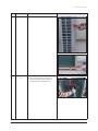
[AM666FXMDCH series]
* Do not change the EMI/outdoor unit main/ Indoor unit main PBA when E461, E467 error occurs
o It is Compressor, inverter PBA related error, therefore it is not related to above PBA
* Make sure to check if service valve is open
o If the service valve is close, damage could occur due to pressure difference during operation
Samsung Electronics
37
Troubleshooting
3-18 Current error / PFC overload error (Error Code : E462, E484)
1. Check items
1) Check the power and restarting after power reset
2) Check the outdoor unit installation and environments
o Check if the outdoor unit inverter PBA related wires
are disconnected. Check the installation environment
3) Check for indoor unit installation environment
4) Check for open service valve
Error CODE
E462
E484
Error description
Outdoor unit total current error
Outdoor unit PFC overload error
Related model
AM666FXMDCH series
AM666FXMDCH series
2. Check procedure
Turn off the power and turn it
on again after 30 seconds
Is the outdoor unit installed correctly?
No
Check the outdoor unit installation and
environment o Check for normal operation o
End service
1. Check for wire disconnection related to outdoor
unit inverter PBA
2. Remove the obstacles on outdoor unit air inlet
and secure enough space
3. Remove the obstacles on outdoor unit air outlet
and secure enough space
Yes
[AM666FXMDCH series]
Is the indoor unit installed correctly??
No
Yes
Is the service valve completely open?
No
Check the indoor unit installation and
environment o Check for normal operation o
End service
1. Remove obstacles on air inlet and secure
enough space
2. Remove obstacles on air outlet and secure
enough space
Open the valve
Yes
Is the compressor operating normally?
No
Change the compressor
Yes
Change the outdoor unit inverter PBA and check for normal
operation o End service
38
Samsung Electronics
Troubleshooting
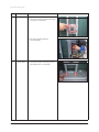
3-19 IPM over current error (Error Code : E464)
1. Check items
1) Check the power and restarting after power reset
2) Check the outdoor unit installation and environments
o Check if the outdoor unit inverter PBA related wires are disconnected. Check the installation environment
3) Check for indoor unit installation environment
4) Check for open service valve
5) Check the assembly status of the compressor and compressor wire
6) Check the compressor wire
2. Check procedure
Turn off the power and turn it
on again after 30 seconds
Is the outdoor unit installed correctly?
No
[AM666FXMDCH series: Check
for disconnected wires]
Yes
Is the indoor unit installed correctly??
Check the outdoor unit installation and
environment o Check for normal operation o
End service
1. Check for wire disconnection related to outdoor
unit inverter PBA
2. Remove the obstacles on outdoor unit air inlet
and secure enough space
No
Check the indoor unit installation and
environment o Check for normal operation o
End service
1. Remove obstacles on air inlet and secure
enough space
2. Remove obstacles on air outlet and secure
enough space
Yes
Is piping/wiring between
the indoor and outdoor unit
done correctly?
No
Re-install them correctly
Yes
Cont.
Samsung Electronics
39
Troubleshooting
IPM over current error (Error Code : E464) (cont.)
Cont.
Is the service valve completely open?
Are the compressor
wires correctly connected to
the compressor?
No
No
Open the valve
Check the connection of the compressor
Yes
Check the compressor
1. Is resistance value between phases of
the compressor same? (U lV, U lW, V lW)
2. Is the wire connected to compressor normal?
(disconnection, wrong connection)
3. Is there any noise when
the compressor rotates?
No
1. Change the compressor: When the resistance
value between phases of the compressor is
different o Turn the power on o Check for
normal operation o End service
2. Reassemble wire: When the wire connection of
the compressor is wrong o Turn the power on
o Check for normal operation o End service
3. Change the compressor: When loud abnormal
noise generates (such as metal grinding), or
severe vibration
Yes
Is the resistance between
compressor body and chassis MegaΩ?
No
Change the compressor
Yes
Is the location and
measured value of the
temperature sensor normal?
No
Turn off the power and change the location
of the temperature sensor or replace it
Yes
Cont.
40
Samsung Electronics
Troubleshooting
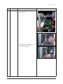
IPM over current error (Error Code : E464) (cont.)
Cont.
Yes
Check the compressor wire
1. Is the compressor wire assembled in
following color? U: RED, V: BLU, W: YEL
o Check for wire disconnection on PBA and COMP.
2. Is the terminal within the compressor wire
housing firmly assembled?
3. Is there any problem,
such as disconnected housing
or cut, on some of
the compressor wire?
No
1. Change the compressor wire o Turn on the
power o End service
2. Change the compressor wire o Turn on the
power o End service
3. Change the compressor wire o Turn on the
power o End service
Yes
W
Change the PCB
V
U
[AM666FXMDCH series]
* Do not change the EMI/outdoor unit main/ Indoor unit main PBA when E464 error occurs
o It is Compressor, inverter PBA related error, therefore it is not related to above PBA
Samsung Electronics
41
Troubleshooting
3-20 DC-Link voltage under/over error (Error Code : E466)
1. Check items
1) Check the power and restarting after power reset
o Is there any problem with input power?
(1 Phase: 220Vac, 3 Phase: 380Vac)
o Does error occur again during operation after power reset?
2) Check the power cable connection, and joint cable connection
3) Check the reactor and reactor wire
4) Check the fuse on the EMI PBA
5) Check the Terminal block, power terminal cabinet and the power wire assembly
2. Check procedure
Turn off the power
Is the power cable connected properly?
No
Re-connect the power cable
[AM666FXMDCH series]
Yes
[Common: Power joint connection failure]
Check the reactor and
reactor wire connection
1. Is wire connection between the reactor l
outdoor unit inverter PBA normal?
2. Is there any problem on reactor coil?
(such as scratch/pressed/
broken terminal/
loose terminal)
No
1. Correctly connect the wire between the reactor
l outdoor unit inverter PBA o Check for
normal operation o End service
2. Change the reactor o Check for normal operation o
End service
[AM666FXMDCH series]
Yes
Cont.
42
Samsung Electronics
Troubleshooting
DC-Link voltage under/over error (Error Code : E466) (cont.)
Cont.
Yes
Is EMI PBA fuse disconnected?
Yes
Change the fuse
[AM666FXMDCH series]
Yes
Check the terminal block
and the power terminal cabinet
1. Is screw on the terminal block firmly assembled?
2. Is power cable and terminal on the power
terminal cabinet firmly assembled?
Yes
1. Connect the terminal block screw and the
power cable oCheck for normal operation o
End service
2. Connect the terminal and the power cable in
the power terminal cabinet o Check for normal
operation o End service
No
Change the outdoor unit inverter PBA and
check for normal operation o End service
Samsung Electronics
43
Troubleshooting
3-21 Gas leak error (Error Code : E554)
1. Check items
1) Check the power and restarting after power reset
o Is there any problem with input power?
(1 Phase: 220Vac, 3 Phase: 380Vac)
o Does error occur again during operation after power reset?
2) Check the compressor and compressor wire assembly
3) Check the outdoor unit installation and environments
o Check if the outdoor unit inverter PBA related wires are disconnected. Check the installation environment
o If there were multiple installation, check if the communication cable and the pipes are installed correctly.
2. Check procedure
Turn off the power and turn it
on again after 30 seconds
Does error occur again?
No
End service
Yes
Check the compressor
and compressor wire assembly
1. Is resistance value between phases of the
compressor same? (U lV, U lW, V lW)
2. Is the wire connected to compressor normal?
(disconnection, wrong connection)
3. Is there any noise when
the compressor rotates?
No
1. Change the compressor: When the resistance
value between phases of the compressor is
different o Turn the power on o Check for
normal operation o End service
2. Reassemble wire: When the wire connection of
the compressor is wrong o Turn the power on
o Check for normal operation o End service
3. Change the compressor: When loud abnormal
noise generates (such as metal grinding), or
severe vibration
Yes
Is the outdoor and indoor unit
pipes/cables correctly installed?
No
Install them correctly
Yes
Cont.
44
Samsung Electronics
Troubleshooting
Gas leak error (Error Code : E554) (cont.)
Cont.
Yes
No
Is the service valve completely open?
Open the valve
Yes
Is the EVA sensor correctly connected?
No
Re-connect the sensor connector
Yes
Is the refrigerant charged?
No
Charge the refrigerant
Yes
Is the refrigerant charged?
Samsung Electronics
45
Troubleshooting
3-22 Others
1. Compressor Vlimit error: E465
If the compressor operation is abnormal, change the compressor and check for normal operation
o If the compressor operation is normal, check the assembly between heat sink plate and if there is no problem, change the inverter
PBA
2. Current sensor error: E468
EEPROM Uploading at indoor main PBA, Check if PCB operation is normal
3. OTP error: E471
Error occurs when the EEPROM DATA in the outdoor unit main PBA and inverter PBA is different from each other. Check the model
name and EEPROM code to use it
4. DC link voltage sensor error: E469
Error occurs when DC LINK value is not normal (DC LINK VOLTAGE: 280~320V)
Check the value of DC link when error occurs and check the reactor disconnection
5. Heat sink temperature error: E474, E500
Error occurs when heat sink of the inverter PBA exceeds rated range
Clean and remove any dust and other foreign substances on the outdoor unit and then check the connection between heat sink and
inverter PBA
Make sure grease is applied properly and screw is firmly fixed
6. Input current sensor error: E485
Detect the input sensor while the set is in stop status to check if there’s any problem
When error occurs, turn on/off the power for number of time and if same error occurs while the power is off, change the inverter PBA
7. EEPROM read/write error: E470
Error occurs when there is no EEPROM data in the set. Check the model name and insert EEPROM for corresponding model or load the
EEPROM data.
46
Samsung Electronics
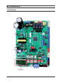
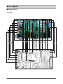
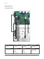
͑غPCB Diagram
غOutdoor Unit PCB
- Main PCB
48
Samsung Electronics
PCB Diagram
Main PCB (cont.)
① CN101-AC INPUT
#1~#3 : 220~240Vac
⑤ CN704-4WAY VALVE 2
#1~#3 : 220~240Vac
⑨ CN806-E2P MODULE
② CN701-HOT GAS
#1~#3 : 220~240Vac
⑥ CN403- TEMP SENSOR
⑦ CN306-MICOM DOWNLOAD
⑧ CN802-EEV 1
#1~#10 : Micom down
#1~4 : EEV signal
#5,6 : DC 12V
⑩ CN002-HIGH P S/W
⑭ CN406-
#1~4 : EEV signal
#5 : DC 12V
⑰ CN305-COMM INV PBA
⑪ CN803-EEV 2
#1~4 : EEV signal
#5 : DC 12V
⑮ CN805-EEV 4
#1~4 : EEV signal
#5 : DC 12V
⑱
CN501-SELECT COOLING
ONLY
⑲ CN401-LOW P SENSOR
#2 : INPUT
#3 : GND
#4 : VCC
CN401-MID P SENSOR
④ CN703-BASE HEATER
#1~#3 : 220~240Vac
#1 : OUT TEMP
#2,4,6,8: GND
#3 : COND TEMP
#5 : DISCHARGE TEMP
#7 : OLP SENSOR
#1 : INPUT
#2 : GND
⑬ CN804-EEV 3
③ CN702-4WAY VALVE 1
#1~#3 : 220~240Vac
CN302-COMM SUB PBA
CN303-COM INDOOR UNIT
⑫ CN001-Flow S/W
#1 : INPUT
#2 : GND
⑯
CN801-EXTERNAL CONTROL
OUT
#1,3 : DC 12V
#2 : ERROR CHECK OUT
#4 : COM CHK OUT
⑳ CN401-HIGH P SENSOR
#1 : INPUT
#3 : GND
#4 : VCC
CN103-EARTH
#1 : INPUT
#2 : GND
#4 : VCC
Samsung Electronics
49
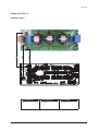
PCB Diagram
Outdoor Unit PCB (cont.)
- Inverter PCB : 1Phase II
① Reactor-A1/B1
#Reactor-A2 : WHT
#Reactor-B2 : WHT
② Reactor-A2/B2
#Reactor-A2 : BLK
#Reactor-B2 : BLK
③ CN31-MAIN COMM
#1 : RXD#2 : TXD
#3 : GND, #4 : DC 5V
#5 : DC 12V, #6 : INV. SMPS signal
④ CN22-Downloader
#1 : RXD_ATARO, #2 : TXD_ATARO
#3, #8 : N.C, #4~#7 : DATA signal
#9 : GND, #10 : DC 5V
⑤ CN21-DAC/ENCODER
For S/W engineer debugging
⑥ CN91-FAN2
#1 : DC 360V
#2 : N.C
#3 : GND
#4 : DC 15V
#5 : FAN RPM
#6 : FAN RPM feedback
⑦ CN90-FAN1
#1 : DC 360V
#2 : N.C
#3 : GND
#4 : DC 15V
#5 : FAN RPM
#6 : FAN RPM feedback
⑧ CN71-COMP.
#1 : COMP. U-phase(RED)
#2 : COMP. V-phase(BLU)
#3 : COMP. U-phase(YEL)
50
Samsung Electronics
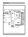
PCB Diagram
Outdoor Unit PCB (cont.)
- EMI PCB : 1Phase
① L1-AC POWER L phase
L1 : BRN
Samsung Electronics
② N1-AC POWER N phase
N1 : SKY-BLU
③ CN01-AC POWER
#1-#3 : AC 220~240V
51
͑غWiring Diagram
غ1 Phase
This Document can not be used without Samsung’s authorization.
52
Samsung Electronics
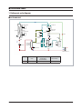
͑غReference Sheet
1. Refrigerant cycle diagram
غOUTDOOR UNIT
%/'&0RWRU
:D\99
&KHFN
99
&RQGHQVRU
+LJK3UHVV
6HQVRU
)$1Ż
jG
7DLU
o
oG
wUV
/RZ3UHVV
6
6HQVRU
7
7FRXW
W
7VXF
2LO
6HSDUDWRU
%/'& 0RWRU
)LOWHU
7GLV
)LOWHU
)LOWHU
7RS
0DLQ((9
7VF
&RPS
SUHVVRU
$FFXPXODWRU
'RXEOHSLSH
'
EO L
RXWWXEH
WHPSHUDWXUH
+RW JDV
E\SDVV
99
³$´
(6&((9
)LOW
)LOWHU
6HUYLFH99
“A”
53
Name
AM036FXMDCH
AM048FXMDCH
RD050MHXGA(EA)
AM053FXMDCH
Service V/V
15.88
19.05
Samsung Electronics
Reference Sheet
2. Nomenclatures
غOUTDOOR UNIT
AM
+
053
+
F+
X+
Classification
AM
M
+
D+
DVM
%8<(5
Rating Voltage
N
INDOOR UNIT (NASA)
A
A(115V, 60Hz,1 Ф )
X
OUTDOOR UNIT (NASA)
B
B(220V, 60Hz,1 Ф )
C
C(208V~230V, 60Hz)
D
D(200V~220V, 50Hz)
E
E(220V~240V, 50Hz)
F
F(208V~230V, 60Hz,3 Ф )
G
G(380V~415V, 50Hz,3 Ф )
H
H(380V, 60Hz,3 Ф )
J
J(460V, 60Hz,3 Ф )
BTU/H(*100)
Version
AA
+
Product Type
Capacity
666
H+
C+
Product Notation
F
2013
K
DVM PLUS (OUTDOOR)
G
2014
V
DVM Inverter (OUTDOOR)
H
2015
L
DVM SLIM (OUTDOOR)
G
DVM GHP (OUTDOOR)
M
DVM MONO (OUTDOOR)
W
DVM WATER (OUTDOOR)
C
DVM GEO(GEOTHERMAL)
(OUTDOOR)
D
DVM PLUS3 (OUTDOOR)
X
DVM PLUS2 (OUTDOOR)
K
K(220V~240V, 50/60Hz, 1 Ф)
M
M(127V, 50Hz)
N
N(380V~415V, 50/60Hz, 3 Ф)
Mode
Product Notation
54
K
DVM PLUS (OUTDOOR)
V
DVM Inverter (OUTDOOR)
L
DVM SLIM (OUTDOOR)
G
DVM GHP (OUTDOOR)
M
DVM MONO (OUTDOOR)
W
DVM WATER (OUTDOOR)
C
DVM GEO(GEOTHERMAL)
(OUTDOOR)
D
DVM PLUS3 (OUTDOOR)
X
DVM PLUS2 (OUTDOOR)
C
COOLING ONLY
H
HEAT PUMP
R
HEAT RECOVERY
Samsung Electronics
͑غCheck Operation & Amount of Refrigerant Automatically Checking
1. Check Operation
1-1 Check Operation
1) What is the Check Operation?
DVM MINI main components defective check and check the status of the installation, provide guidelines that can promptly
and accurately resolve the problems that may occur in the field.
If does not end the Automatic Commissioning, normal operation is impossible to enter, it should protect the system from
the abnormal state. ("UP")
2) Check operation Preliminary checking.
(1) Check the Power cable of Indoor / Outdoor Unit and communication wire.
(2) Turn on the power 3 hours before to start the Check operation. (Crankcase heater to be heated sufficiently.)
(3) Check before applying power voltage and phase using a phase tester and voltmeter.
phase-to-phase, 220V (R-N, S-N, T-N).
(4) Power on, perform the tracking. (Outdoor Unit inspects Indoor Unit and optional.)
(5) Card to verify the installation of the control box front : must be record the installation details.
※ Necessarily turn on the power 3 hours before to start the Check operation.
3) How to use the Check operation.
(1) Check operation, use the Key Mode. (Pressing the K1 Tact Switch for a long time)
- If does not complete the Check operation, Display the "UP"(Unprepared) on the LED after checking communication.
(Compressor to operate general operation is prohibited.)
※ UP Mode will be turned off automatically at finished the Check operation.
- Check operation is carried out by the operating conditions.
(From 30 minutes to maximum 50 minutes)
- During Check operation due to the valve check, the noise can be generated. (Sustained abnormal noise occurs, check it)
(2) When an error occurs during the Check operation, check the error code in the product and then service it.
(3) Shut down the Check operation, resulting report will be issued using the S-NET or S-CHECKER.
- The resulting report of the "Undetermined"item, troubleshoot the accordance with the service manual.
- Troubleshoot all the items of "Undetermined" and then restart the Check operation.
(4) Check the following as Check operation. (Heating / Cooling)
- Check the Cooling and Heating operation is progressing well.
- Individual Indoor Unit control : check the wind direction, wind speed.
- Check the Indoor and Outdoor abnormal noise.
- Check the drainage of the Indoor Unit cooling operation.
- More operation : Checking status by using the S-NET.
(5) Refer to manual and explain air conditioner usage to user.
(6) Deliver this installation guide so that customer retain.
Samsung Electronics
55
Check Operation & Amount of Refriherant Automatically Checking
※ If out of warranty coverage and bounds, installation, operation according to the conditions the some of items displayed as
"Undetermined" and judgment is not.
Ex) system that module installed : If the outdoor unit is not operation by the load on the indoor and outdoor, corresponding
Sub Outdoor Unit does not judge the inspection entries. (However, Indoor / Outdoor Temperature sensor and Pressure
sensor judgment is available.)
4) Inspection item of the Check operation
During the Check operation of the DVM MINI, defect check items are as follows.
- Indoor Unit Temperature sensor (Indoor temperature of each Indoor Unit, EVA In/Out Temperature sensor)
- Outdoor Unit Temperature sensor
(Outdoor temperature of each Outdoor Unit, Cond_Out, Suction, Liquid Pipe Temperature sensor)
- Outdoor Unit High Pressure sensor & Low Pressure sensor
- Outdoor Unit Compressor : Judgment of the operation current
- Cycle state judgment of the Outdoor Unit
- Outdoor Unit 4Way Valve : Judgment of the operation
- Outdoor Unit MAIN EEV : Judgment of the operation
(※ The operation mode of the Automatic Commissioning : "Heating" only if the detection.)
Outdoor Temperature (˚C)
5) Warranty Coverage of the Check operation
As follows, in order to accurately measure Indoor / Outdoor temperature conditions in the Check operation is carried out.
Cooling
Heating
Indoor Temperature (˚C)
- Heating / Cooling mode is automatically selected of Check operation.
- Oblique line marked area in the during operation of the system can be protection control.
(Check operation of normal judgment can be difficult by the protection control operation.)
- If out of warranty coverage and the boundary area : Check operation judgment accuracy may be reduced.
56
Samsung Electronics
Check Operation & Amount of Refriherant Automatically Checking
1-2 How to troubleshoot of the "Undetermined"
1) Indoor Unit Temperature sensor
C Inspection item : Indoor temperature of each Indoor Unit, EVA In / Out Temperature sensor
C Error code: None (The resulting report "Undetermined")
C Determine the status of the Temperature sensor of the Indoor Unit installed before the compressor start.
C Commissioning methods
Blast operation for more than 10 minutes
Is deviations of the Indoor Unit Temperature
sensors, more than 10℃?
※ Resistance measurement method After
separating the Temperature sensor connector
from the PCB, measure the resistance value
between the two terminals.
Yes
Is Indoor temperature of the Indoor Unit by wired remote
control setting?
No
Indoor Temperature
sensor setting(Remote
control → indoor unit)
No
Does Temperature sensor connection wire of
Outdoor Unit properly connect?
No
Confirmation and
Measures
[Discharge
Temperature sensor
resistance value]
Temperature(℃)
Resistance(Ku)
70
60
50
40
30
20
10
0
-10
2.2
3.0
4.2
5.8
8.3
12.1
18.0
27.3
43.0
Yes
Is Outdoor Unit Temperature sensor resistance
value normal?
No
Replace sensor
Yes
Check the breakaway of sensor or replace PCB
Is deviations of the Indoor Unit Temperature
sensors, less than 10℃?
Complete
[Caution]
- If the Outdoor Unit with a history of operation (Automatic commissioning inclusion) : Must be carried out Automatic Commissioning after 1
hour from final operation stopped.
Samsung Electronics
57
Check Operation & Amount of Refriherant Automatically Checking
2) Outdoor Unit Temperature sensor
C Inspection item : Outdoor temperature of each Outdoor Unit, Cond_Out, Suction, Liquid pipe temperature sensor
C Error code: None (The resulting report "Undetermined")
C Determine the status of the Temperature sensor of the each Outdoor Unit installed before the compressor start.
C If the judgment of Outdoor Unit Temperature sensor is "Undetermined" : Checking in accordance with the following order.
Must wait more than 1 hour
Is deviations of the each
Outdoor Unit Temperature sensors,
more than 10℃?
No
※ Resistance measurement method After
separating the Temperature sensor connector
from the PCB, measure the resistance value
between the two terminals.
Yes
Is Temperature sensor properly assembled?
[Discharge
Temperature sensor
resistance value]
Temperature(℃)
No
Yes
Is Temperature
sensor connector properly connect?
No
Yes
Is Temperature sensor resistance value normal?
No
7 0
2 2.
6 0
3 0.
5 0
4 2.
4 0
5 8.
3 0
8 3.
2 0
1 2
1 .
1 0
1 8
0 .
0
2 7
3 .
- 01
4 3
0 .
Replace sensor
Yes
Check the breakaway
of sensor or replace PCB
No
Is deviations of the each
Outdoor Unit Temperature sensors, less than 10℃?
Yes
Complete
[Caution]
- If the Outdoor Unit with a history of operation (Automatic commissioning inclusion) : Must be carried out Automatic Commissioning after 1
hour from final operation stopped.
58
Samsung Electronics
Check Operation & Amount of Refriherant Automatically Checking
3) Pressure sensor
C Inspection item : High/Low Pressure sensor of the independent installed Outdoor Unit.
CError code: None (The resulting report "Undetermined")
C Determine the status of the Pressure sensor of the independent installed Outdoor Unit before the compressor start.
C If the judgment of Outdoor Unit Pressure sensor is "Undetermined" : Checking in accordance with the following order.
Vacuum mode of Outdoor Unit
Check the pressure sensor breakdown
※ Check the Pressure sensor breakdown after the saturation pressure
of the outdoor temperature or connect the manifold gauge to check the pressure
.
Is Pressure sensor connector properly connect?
No
Yes
Is voltage 5V between
3, 4 pin of PCB Pressure sensor terminal?
No
Replace Hub PCB
Yes
Is deviation of outdoor
unit as following?"High pressure Max
/Min deviation : less than 2"
No
Replace PCB
Yes
Complete
[Caution]
- If the Outdoor Unit with a history of operation (Automatic commissioning inclusion) : Maintain the vacuum mode for more than 5 minutes.
Samsung Electronics
59
Check Operation & Amount of Refriherant Automatically Checking
4) Abnormal operation of the Compressor
C Inspection item : Operation current of Outdoor Unit Compressor.
C Error code: None (The resulting report "Undetermined")
C Determine the status of the operating current of the each Outdoor Unit Compressor.
C If the judgment of operation current of Outdoor Unit Compressor is "Undetermined" :
Checking in accordance with the following order.
Is Outdoor Unit
No
status normal?
Yes
When Outdoor Unit is
stopped state : Is current(CT)value of Compressor 0?
No
Replace Inverter PCB
Yes
Is resistance between
the phase of compressor normal?
No
Yes
Restart Automatic Commissioning
after current meter installation.
Is the current
measurement results of the compressor and CT
sensor have the same value?
No
Replace Inverter PCB
Yes
Is Compressor current(CT) value normal?
No
Is refrigerant
in the system properly?
Yes
No
Yes
Adjusts the refrigerant
(Addition / Emitted)
IIs operation
current of Compressor
normal?
Yes
No
Replace Compressor
Complete
60
Samsung Electronics
Check Operation & Amount of Refriherant Automatically Checking
5) Cycle status
C Inspection item : Cycle status of Outdoor Unit.
C Error code: None (The resulting report "Undetermined")
C Determine the Cycle status of the each Outdoor Unit.
C If the judgment of Cycle status is "Undetermined" : Checking in accordance with the following order.
Commissioning results,
is Valve and Pressure sensor normal?
No
Check the corresponding Valve
/Sensor and Compressor.
Yes
Is Discharge Temperature
sensor of corresponding Outdoor Unit
normal?
No
Inspection and measures of
Discharge Temperature sensor.
(Assembly status, connector,
resistance, etc.)
[Discharge
Temperature sensor
resistance value]
Temperature(℃)
Yes
When commissioning,
does maintain Thermo On status of
Indoor Unit?
No
Indoor ventilation
Yes
Is refrigerant in the system properly?
※ Resistance measurement method
After separating the Temperature sensor
connector from the PCB, measure
the resistance value between
the two terminals.
No
Adjusts the refrigerant
(Addition / Emitted)
1 30
8 9.
1 20
1 12 .
10
1 85 .
80
3 20 .
60
5 90 .
25
2 0 00 .
20
2 4 02 .
10
3 6 02 .
0
5 5 03 .
Yes
Complete
Samsung Electronics
61
Check Operation & Amount of Refriherant Automatically Checking
6) 4Way Valve
C Inspection item : 4Way Valve of Outdoor Unit.
C Error code: None (The resulting report "Undetermined")
C Determine the 4Way Valve operation status of the each Outdoor Unit.
C If the judgment of 4Way Valve is "Undetermined" : Checking in accordance with the following order.
Commissioning results,
is Valve and Pressure sensor normal?
No
Check the corresponding Pressure sensor.
Yes
Is 4Way Valve connector properly connect?
No
Yes
Is 4Way Valve coil normal?
(Wire breaking, operation impossible, etc.)
No
Replace Valve coil
Yes
Is PCB Output signal normal?
No
Replace PCB
Yes
Replace 4Way Valve Body
(Retry the Automatic Commissioning :
If the continuous "Undetermined" is displayed.)
Complete
62
Samsung Electronics
Check Operation & Amount of Refriherant Automatically Checking
7) Main EEV
C Inspection item : Main EEV of Outdoor Unit.(Automatic Commissioning : Heating only )
C Error code: None (The resulting report "Undetermined")
C Determine the Main EEV operation status of the each Outdoor Unit.
C If the judgment of Main EEV is "Undetermined" : Checking in accordance with the following order.
No
COMMISSIONING RESULTS, IS VALVE AND
PRESSURE SENSOR NORMAL?
Check the Valve and Pressure sensor.
Yes
No
IS MAIN EEV CONNECTOR NORMAL?
Confirmation and Measures
Yes
IS MAIN EEV COIL NORMAL?
(RESISTANCE, WIRE BREAKING,
OPERATION IMPOSSIBLE, ETC.)
No
Replace Coil
Yes
No
S PCB OUTPUT SIGNAL NORMAL?
REPLACE HUB PCB
Yes
Replace Main EEV
※ Main EEV coil resistance value based (Measured temperature is 20°C)
Complete
Main EEV Coil
Voltage
(VDC)
between the
phase (Ω)
1-3 Automatic Commissioning Error Code
Division
Dedicated Error Code
Error Code
E503
E505
E506
Description
Service Valve is closed
High pressure sensor breakdown
Low pressure sensor breakdown
Remark
Refer to "Service Valve"
Refer to "High/Low pressure sensor
(Module installed)"
※Other error codes : Refer to Service Manual.
Samsung Electronics
63
2. Amount of Refrigerant Automatically Checking
Through the detect operation is the ability to verify automatically for the amount of refrigerant.
Start
"K2" Tact Switch : Press the 5 times.S
(Normal)
ignal input
S-CHECKERsignal input
Check the amount of refrigerantC
heck the amount of refrigerant
Judge the amount of refrigerant
Judge the amount of refrigerant
(Excessive)
(Undetermined)
Normal
Excessiveof
refrigerant
amount
refrigerant
amount
Over-cooling Undetermined
Complete
[Caution]
B If escape the warranty temperatures, can not get the accurate results.
- Indoor : 20~30°C
- Outdoor : 5~43°C
B If operation cycle is not stable, refrigerant detection operation can be forced to shut down.
B If did not operation for a long time, or when running the heating operation, the accuracy may be lower.
Therefore carried out for more than 30 minutes cooling operation.
B Depending on the installation environment, system protection operation is performed, in this case,
the amount of refrigerant checked result maybe inaccurate.
[How to troubleshoot the judged results]
B Excessive of refrigerant amount : After the 5% emissions of calculated total refrigerant amount, retry refrigerant detection operation.
B Deficiency of refrigerant amount : After the 5% addition of calculated total refrigerant amount, retry refrigerant detection operation.
B Undetermined : Refrigerant detection operation confirms that is performed in warranty temperatures area.
Ensure that there is no other problems in the system by Commissioning.
64
Samsung Electronics
*631*/2%$/6(59,&(3$571(51(7:25.
$UHD
:HE6LWH
(XURSH&,60LGHDVW$IULFD JVSQVDPVXQJFVSRUWDOFRP
$VLD
JVSQVDPVXQJFVSRUWDOFRP
1RUWK/DWLQ$PHULFD
JVSQVDPVXQJFVSRUWDOFRP
&KLQD
FKLQDVDPVXQJSRUWDOFRP
This Service Manual is a property of Samsung Electronics Co., Ltd.
Any unauthorized use of Manual can be punished under applicable
International and/or domestic law.
© Samsung Electronics Co., Ltd. February. 2013.
Printed in Korea.
Code No. AC-00013E_1