1
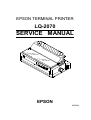
EPSON TERMINAL PRINTER
LQ-2070
SERVICE MANUAL
EPSON
4006244
NOTICE
•
•
•
•
All right reserved. Reproduction of any part of this manual in any form wharsoever without SEIKO EPSON’s express
written permission is forbidden.
The contents of this manual are subject to change without notice.
All efforts have been made to ensure the accuracy of the contents of this manual. However, should any errors be
detected, SEIKO EPSON would greatly appreciate being informed of them.
The above notwithstanding SEIKO EPSON can assume no responsibility for any errors in this manual or the
consequences thereof.
Copyright 1995 by SEIKO EPSON CORPORATION
Nagano, Japan
PRECAUTIONS
Precautionary notations throughout the tect are categorized relative to 1) personal injury, and 2) damage to
equipment:
DANGER
Singnals a precaution which, if ignored, could ressult in serious or fatal personal
injury, Great caution should be exercised in performing procedures preceded by
a DANGER headings.
WARNING
Singnals a precaution which, if ignored, could result in damage to equipment.
The precautionary measures itemized below should always be observed when performing repair
/maintenance procedures.
DANGER
1. ALWAYS DISCONNECT THE PRODUCT FROM BOTH THE POWER SOURCE AND THE
HOST COMPUTER BEFORE PERFORMING ANY MAINTENANCE OR REPAIR PROCEDURE.
2. NO WORK SHOULD BE PERFORMED ON THE UNIT BY PERSONS UNFAMIAR WITH
BASIC SAFETY MEASURES AS DICTATED FOR ALL ELECTRONICS TECHNICIANS IN
THEIR LINE OF WORK
3. WHEN PERFORMING TESTING AS DISCATED WITHIN THIS MANUL, DO NOT CONNECT
THE UNIT TO A POWER SOURCE UNIT INSTRUCTED TO DO SO. WHEN THE POWER
SUPPLY CABLE MUST BE CONNECTED, USE EXTREME CAUTION IN WORKING ON
POWER SUPPLY AND OTHER ELECTRONIC COMPONENTS.
WARNING
1. REPAIRS ON EPSON PRODUCT SHOULD BE PERFORMED ONLY BY AN EPSON
CERTIFIED REPAIR TECHNICIAN.
2. MAKE CERTAIN THAT THE SOURCE VOLTAGE IS THE SAME AS THE RATED VOLTAGE,
LISTED ON THE SERIAL NUMBER/RATIG PLATE. IF THE EPSON PRODUCT HAS A
PRIMARY-AC RATING DIFERENT FORM THE AVAILABLE POWER SOURCE, DO NOT
CONNECTE IT TO THE POWER SOURCE.
3. ALWAYS VERIFY THAT THE EPSON PRODUCT HAS BEEN DISCONNECTED FROM THE
POWER SOURCE BEFORE REMOVING OR REPLACING PRINTED CIRCUIT BOARDS
AND/OR INDDIVIDUAL CHIPS.
4. IN ORDER TO PROTECT SENSITIVE m P CHIPS AND CIRCUITRY, USE STATIC
DISCHARGE EQUIPMENT, SUCH AS ANTI-STATIC WRIST STRAPS, WHEN ACCESSING
INTERNAL COMPONENTS.
5. REPLACE MALFUNCTIONING COMPONENTS ONLY WITH THOSE COMPONENTS
RECOMMENTED BY THE MAANUFACTURE; INTRODUCTION OF SECOND-SOURCE ICs
OR OTHER NONAPPROVED COMPONENTS MAY DAMAGE THE PRODUCT AND VOID
ANY APPLICABLE EPSON WARRANTY.
PREFACE
This manual describes functions, theory of electrical and mechanical operations, maintenance, and repair of
the FX-2170. The instructions and procedures included herein are intended for the experienced repair
technician, and attention should be given to the precautions on the preceding page. The chapters are
organized as follows:
Chapter 1
-
Provides a general product overview, Lists specifications, and illustrates the main
components of the printer.
Chapter 2
-
Describes the theory of printer operation.
Chapter 3
-
Includes a step-by-step guide for product disassembly and assembly.
Chapter 4
-
Includes a step-by step guide for addjustement.
Chapter 5
-
Provides Epson-approved techniques for troubleshooting.
Chapter 6
-
Describes prevetive maintenance techniques.
❇ The contents of this manual are subject to change without notice.
REVISION SHEET
Revision
Issued Date
Revision Page
Rev. A
April 8,1996
1st issued
TABLE OF CONTENTS
CHAPTER 1.
CHAPTER 2.
CHAPTER 3.
CHAPTER 4.
CHAPTER 5.
CHAPTER 6.
APPENDIX
GENERAL DESCRIPTION
OPERATION PRINCIPLES
DISASSEMBLY AND ASSEMBLY
ADJUSTMENTS
TROUBLESHOOTING
MAINTENANCE
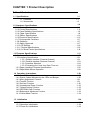
CHAPTER 1 Product Description
Table of Contents
1-1
1.1 Specifications
1.1.1 Features. . . . . . . . . . . . . . . . . . . . . . . . . . . . . . . . . . . . . . . . . . . . 1-1
1.1.2 Accessories . . . . . . . . . . . . . . . . . . . . . . . .. . . . . . . . . . . . . . . . . . . 1-3
1-4
1.2 Hardware Specifications
1.2. I Printing Method. . . . . . . . . . . . . . . . . . . . . . . . . . . . . . . . . . . . .
. 1-4
.
.
.
.
.
.
.
.
1-5
1.2.2 Printing Specifications . . . . . . . . . . . . . . . . . . . . . . . . . . . . . . .
1.2.3 Paper Handling Specifications . . . . . . . . . . . . . . . . . . . . . . . . . . . . . . . ...1-6
1.2.4 Paper Specifications . . . . . . . . . . . . . . . . . . . . . . . . . . . . . . . . . 1-8
1.2.5 Ribbon Specifications . . . . . . . . . . . . . . . . . . . . . . . . . . . . . . ... ..... 1-16
1.2.6 Electrical Specifications. . . . . . . . . . . . . . . . . . . . . . . . . . . . . . . . . . .....1-16
1.2.7 Environmental Conditions . . . . . . . . . . . . . . . . . . . . . . . . . . . . . . . . . . . . . 1-17
1.2.8 Reliability. . . . . . . . . . . . . . . . . . . . . . . . . . . . . . . . . . . . . . . . . .- ...., .. 1-17
1.2.9 Safety Approvals. . . . . . . . . . . . . . . . . . . . . . . . . . . . . . . . . . . . . . . .....1-17
1.2.10 CE Marking . . . . . . . . . . . . . . . . . . . . . . . . . . . . . . . . . . . . . . . . . . .....1-18
1.2.11 Physical Specifications . . . . . . . . . . . . . . . . . . . . . . . . . . . . . . . . . .....1-18
1.2.12 Cut Sheet Feeder Specifications. . . . . . . . . . . . . . . . . . . . . . . . . . . . . . . 1-18
1-20
1.3 Firmware Specifications
1.3.1 Control Codes and Fonts . . . . . . . . . . . . . . . . . . . . . . . . . . . . . . . . .....1-20
1.3.21nterface Specifications . . . . . . . . . . . . . . . . . . . . . . . . . . . . . . . . . . .....1-21
1.3.2.1 Parallel Interface (Forward Channel) . . . . . . . . . . . . . . . . . . . . .. 1-21
1.3.2.2 Parallel interface (Reverse Channel) . . . . . . . . . . . . . . . . . . . . . 1-23
1.3.2.3 Interface Selection . . . . . . . . . . . . . . . . . . . . . . . . . . . . . . . . .. ..1-24
1.3.2.4 Preventing the Host from Data Time-out . . . . . . . . . . . . . . .....1-24
1.3.3 Paper Handling Firmware Specifications . . . . . . . . . . . . . . . . . . . . . . . . . 1-25
1.3.4 PaperWidth Sensor Operation. . . . . . . . . . . . . . . . . . . . . . . . . . . . . . . . . 1-28
1-29
1.4 Operating Instructions
1.4.1 Control Panel Operation . . . . . . . . . . . . . . . . . . . . . . . . . . . . . . . . . . .. ..1-29
1.4.2 Status Codes Indicated by the LEDs and Beeper . . . . . . . . . . . . . . .....1-30
1.4.3 Micro Adjustment Function . . . . . . . . . . . . . . . . . . . . . . . . . . . . . . . .....1-31
1.4.4 TearOff Function. . . . . . . . . . . . . . . . . . . . . . . . . . . . . . . . . . . . . . . .....1-31
1.4.5 Self-test Function. . . . . . . . . . . . . . . . . . . . . . . . . . . . . . . . . . . . . . . .....1-32
1.4.6 Hexadecimal Dump Function . . . . . . . . . . . . . . . . . . . . . . . . . . . . . . . . ..1-32
1.4.7 Default Setting Function . . . . . . . . . . . . . . . . . . . . . . . . . . . . . . . . . .....1-33
1.4.8 EEPROM Clear Function . . . . . . . . . . . . . . . . . . . . . . . . . . . . . . . . .....1-33
1.4.9 Bidirectional Adjustment Function . . . . . . . . . . . . . . . . . . . . . . . . . . . . . . . 1-34
1.4.10 Quiet Mode Function . . . . . . . . . . . . . . . . . . . . . . . . . . . . . . . . . . . . . . ..1-34
1.5 Initialization
1-34
1.5.1 Software initialization. . . . . . . . . . . . . . . . . . . . . . . . . . . . . . . . . . . . .....1-34
1.5.2 Operation initialization. . . . . . . . . . . . . . . . . . . . . . . . . . . . . . . . . . . .....1-34
1.5.3 Power On initialization. . . . . . . . . . . . . . . . . . . . . . . . . . . . . . . . . . . .....1-34
1-35
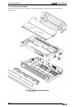
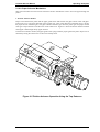
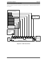
1.6 MAIN COMPONENTS
1.6.1 C186 MAIN Board Assembly. . . . . . . . . . . . . . . . . . . . . . . . . . . . . . . . . . 1-36
1.6.2 C166 PSB/PSE Board Assembly . . . . . . . . . . . . . . . . . . . . . . . . . . . . . . 1-36
1.6.3 C165 PNL Board Assembly. . . . . . . . . . . . . . . . . . . . . . . . . . . . . . . . . . . 1-37
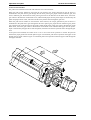
1.6.4 Printer Mechanism . . . . . . . . . . . . . . . . . . . . . . . . . . . . . . . . . . . . . . . . . 1-37
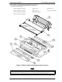
1.6.5 Housing Assembly. . . . . . . . . . . . . . . . . . . . . . . . . . . . . . . . . . . . . . . . . . 1-38
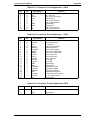
List of Figures
Figure 1-1. Exterior View of the LQ-2070 . . . . . . . . . . . . . . . . . . . . . . . . . . . . . . 1-2
Figure l-2. Pin Configuration . . . . . . . . . . . . . . . . . . . . . . . . . . . . . . . . . . . . . . . 1-4
Figure 1-3. Printable Area for Cut Sheets. . . . . . . . . . . . . . . . . . . . . . . . .“. . . . . . 1-9
Figure 1-4. Printable Area for Envelopes and Card Stock . . . . . . . . . . . . . . . . 1-11
Figure l-5. PrintableAreafor Continuous Paper . . . . . . . . . . . . . . . . . . . . . . . 1-13
Figure 1-6. Label Size. . . . . . . . . . . . . . . . . . . . . . . . . . . . . . . . . . . . . . . . . . . . 1-14
Figure 1-7. Printable Area for Roll Paper . . . . . . . . . . . . . . . . . . . . . . . . . . . . . 1-15
Figure l-8. Data Transmission Timing . . . . . . . . . . . . . . . . . . . . . . . . . . . . . . . 1-22
Figure l-9. Control Panel . . . . . . . . . . . . . . . . . . . . . . . . . . . . . . . . . . . . . . . . . 1-29
Figure 1-10. Self-test Printout. . . . . . . . . . . . . . . . . . . . . . . . . . . . . . . . . . . . . . . 1-32
Figure l-11. Hexadecimal Dump Printout. . . . . . . . . . . . . . . . . . . . . . . . . . . . . 1-32
Figure l-12. Main Components, . . . . . . . . . . . . . . . . . . . . . . . . . . . . . . . . . . . . 1-35
Figure l-13. C186MAlN Board Assembly.. . . . . . . . . . . . . . . . . . . . . . . . . . . 1-36
Figure l-14. C166 PSB/PSE Board Assembly . . . . . . . . . . . . . . . . . . . . . . . . . 1-36
Figure l-15. C165 PNLBoardAssembly . . . . . . . . . . . . . . . . . . . . . . . . . . . . . 1-37
Figure l-16. Printer Mechanism . . . . . . . . . . . . . . . . . . . . . . . . . . . . . . . . . . . . 1-37
Figure l-17. Housing Assembly . . . . . . . . . . . . . . . . . . . . . . . . . . . . . . . . . . . . 1-38
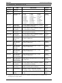
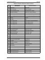
List of Tables
Table 1-1. Items Included with the Printer . . . . . . . . . . . . . . . . . . . . . .........1-3
Table 1-2. Consumables . . . . . . . . . . . . . . . . . . . . . . . . . . . . . . . . . . . . . . . . .. .1-3
Table 1-3. Optional Units . . . . . . . . . . . . . . . . . . . . . . . . . . . . . . . . . . . . . . . “ “ “ .1-3
Table l-4. PrintSpeed and Printable Columns . .........................1-5
Table l-5. Print Resolution. . . . . . . . . . . . . . . . . . . . . . . . . . . . . . . . . .........1-5
Table 1-6. Paper Path and Paper Types . . . . . . . . . . . . . . . . . . . . . ..........1-6
Table l-7. PaperThickness Lever Positions.. . . . . . . . . . . . . . . . . . . . . . . . . . . 1’7
Table 1-8. Specifications for Cut Sheets (Single Sheet, not Multipart) . .......1-8
Table 1-9. Specifications for Cut Sheets (Multiparty). . . . . . . . . . . . . . . . . . . . . .. 1-8
Table l-l O. Printable Area for Cut Sheets. . . . . . . . . . . . . . . . . . . . . . . .......1-9
Table l-11. Specifications for Envelopes . . . . . . . . . . . . . . . . . . . . . . . . . .....1-10
Table 1-12. Specifications for Card Stock . . . . . . . . . . . . . . . . . . . . . . . . .....1-10
Table 1-13. Printable Area for Envelopes and Card Stock . . . . . . . . . . . .....1-11
Table 1-14. Specifications for Continuous Paper (Single Sheet and Multipatt ) 1-12
Table 1-15. Printable Area for Continuous Paper . . . . . . . . . . . . . . . . . . . . .. .1-13
Table 1-16. Specifications for Continuous Paper with Labels . . . . . . . . . .....1-14
Table 1-17. Specifications for Roll Paper. . . . . . . . . . . . . . . . . . . . . . . . . .....1-15
Table 1-18. Printable Area for Roll Paper . . . . . . . . . . . . . . . . . . . . . . . . .....1-15
Table 1-19. Ribbon Specifications . . . . . . . . . . . . . . . . . . . . . . . . . . . . . . .....1-16
Table 1-20. Electrical Specifications for 120 V Version. . .................1-1 6
Table 1-21. Electrical Specifications for 220/240 V Version . . . . . . . . . . .....1-16
Table 1-22. Environmental Conditions. . . . . . . . . . . . . . . . . . . . . . . . . . . .....1-17
Table 1-23. Reliability. . . . . . . . . . . . . . . . . . . . . . . . . . . . . . . . . . . . . . . . . .. ..1-17
Table 1-24. Safety Information for Printer Models . . . . . . . . . . . . . . . . . . . . .. .1-17
Table 1-25. CE Marking . . . . . . . . . . . . . . . . . . . . . . . . . . . . . . . . . . . . . . . . .. .1-18
Table 1-26. Physical Specifications . . . . . . . . . . . . . . . . . . . . . . . . . . . . . .....1-18
Table 1-27. Hopper Capacity. . . . . . . . . . . . . . . . . . . . . . .................1-1 8
Table 1-28. Stacker Capacity. . . . . . . . . . . . . . . . . . . . . . . . . . . . . . . . . . .....1-19
Table 1-29. Environmental Conditions. . . . . . . . . . . . . . . . . . . . . . . . . . . .....1-19
Table 1-30. Character Tables . . . . . . . . . . . . . . . . . . . . . . . . . . . . . . . . . .....1-20
Table 1-31. Pin Assignment of Forward Channel . . . . . . . . . . . . . . . . . . . . .. .1-21
Table 1-32. Minimum and Maximum Timings for Data Transmission . . . .....1-22
Table 1-33. Pin Assignments for Reverse Channel. . . . . . . . . . . . . . . . . . . . . .1-23
Table -34. Paper Handling Sequence 1 . . . . . . . . . . . . . . . . . . . . . . . . . .....1-25
Table -35. Paper Handling Sequence 2. . . . . . . . . . . . . . . . . . . . . . . . . .....1-25
Table -36. Paper Handling Sequence 3. . . . . . . . . . . . . . . . . . . . . . . . . . . . . . 1-26
Table -37. Paper Handling Sequence 4. . . . . . . . . . . . . . . . . . . . . . . . . . . . . . 1-26
Table -38. Paper Handling Sequence 5. . . . . . . . . . . . . . . . . . . . . . . . . . . . . . 1-27
Table -39. Paper Handling Sequence 6. . . . . . . . . . . . . . . . . . . . . . . . . .....1-27
Table -40. PaperWidth SensorOperation. . . . . . . . . . . . . . . . . . . . . . . . . . . . 1-28
Table 1-41. Operations in Normal Mode . . . . . . . . . . . . . . . . . . . . . . . . . .....1-29
Table l-42. 0perationsat Power On....... . . . . . . . . . . . . . . . . . . . . . . . . . . 1-30
Table 1-43. Operations for Default Setting Mode. . . . . . . . . . . . . . . . . . . . . .. .1-30
Table l-44. indicators and Beeper . . . . . . . . . . . . . . . . . . . . . . . . . . . . . . . . . . . 1-30
Table 1-45. EEPROM Initialization Settings. . . . . . . . . . . . . . . . . . . . . ... , .. .1-33
Product Description
LQ-2070 Sendce Manual
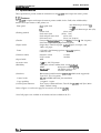
1.1 Specifications
These specifications provide statistical information for the LQ-2070 serial impact dot matrix printer.
1.1.1. Features
The LQ-2070 is a 24pin serial impact dot-matrix printer suitable for the VAR (value addedreseller)
market. The major features of this printer are:
. Print speed
300 characters per second (cps)
275 CPS
92 cps at 10 characters per inch (cPi)
High speed draft
Draft
~Q
(front, rear)
(front, rear)
(front, rear)
(front, rear, bottom)
●
Feeding method
Friction feed
Push tractor feed
Push and pull tractor feed
Pull tractor feed
●
Feeder
Front push tractor(option), rear push &actor, CSF bin 1 / bin 2 (option)
Pull tractor (option), roll paper holder (option)
●
Paper/media
Single sheet, continuous paper, multipart paper, envelopes, card
labels, roll paper
. Fonts
9 LQ and 1 draft bitmap typefaces, 4 Sarable typefaces,
8 barcode fonts
●
Character tables
Standard version
NLSP version
11 tables
20 tables
●
Input buffer
64KB
●
Acoustic noise
51 dB (A), 1S0 7779 pattern
●
Reliability
Total print volume 6 million lines, except printhead
MTBF
6000 power on hours (POH)
Printhead life
200 million strokes/wire
Ribbon life
8 million characters
●
Interfaces
Bidirectional parallel interface (IEEE-P1284 nibble mode supported)
Type B I/F Level 2 (option)
. Control codes
ESC/P2 and IBM 2390/2391 plus emulation
. Copy capability
1 original+ 3 copies
●
Control panel functions
Font, Pause, Condensed Pause, Tear off, Bin, LF/FF, Load/Eject, Micro
Adjust, Default Setting
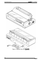
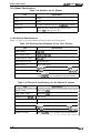
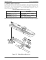
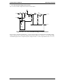
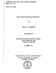
Refer to Figure 1-1 on the next page for an exterior view of the LQ-2070.
Note: Roll paper is not available on all models and not available in the U.S.
Rev.A
1-1
Product Description
LQ-2070 Service Manual
Figure 1-1 Exterior View of the LQ-2070
1-2
Rev.A
Product Description
LCk2070 Service Manual
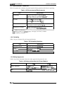
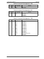
1.1.2. Accessories
●
Items included in the printer carton
Table 1-1 Items Included with the Printer
Quantity
Enclosed Items
User’s guide
1
Driver diskette
1
Ribbon cartridge
1
Power cord
1
. Consumables
Table 1-2 Consumables
Part Number
Consumable Item
Ribbon cartridge
S015083/S01 5086
Ribbon pack
soloo31/sol 0033
. Options
Table 1-3 Optional Units
Description
Unit
High-capacity cut sheet feeder 1 (bin 1)
Second bin cut sheet feeder 2 (bin 2)
Pull tractor unit
Roll paper holder
!
C80673*
I
C80674*
I
C80032*
#831 O
Serial l/F card
C82305* / C82306*
32KB intelligent serial l/F card
C82307* / C82308*
32KB intelligent parallel l/F card
C8231O*/C82311•
Local Talk l/F card
C82312*
32KB IEEE-488 l/F card
C82313*
Coax l/F card
C82314*
Twinax l/F card
C82315*
Ethernet l/F card
C82331•
* The number represented by an asterisk varies, depending on the country.
Note: Roll paper is not available on all models and not available in the U.S.
Rev.A
1-3
LQ-2070 Servioe Manual
Product Description
1.2 Hardware Specifications
This section provides detailed hardware specifications for the LQ-2070.
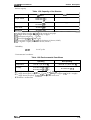
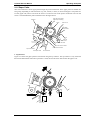
1.2.1 Printing Method
. l?rintig method
Impact dot matrix
. Color
. Number of pins
Black
24 pins
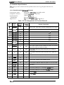
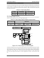
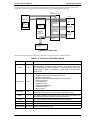
. Pin arrangement
● print Pin diameter
12x 2 staggered
0.2 mm (0.0079 inch)
f)=108°*
0.2°
J<! >
#2
‘:~9Tf
.
~1I18O')
~’~gd’re”’on
—
1
T #4
0.141mm
7 (1/180’)
+#6
~
#7
*#8
+#9
3.246mm
(23/180”)
+#l
b#12
b$13
I
0,,5
;
#l?
I
T #16
I
9#18
T
T#19
+#21
v
b #lo
1
4 #23
0,423 mm(l160’) \
1=
>
Head center
I
1
I
I
!/
r 1-
+$20
+#22
-l
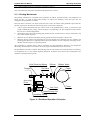
Figure 1-2. Pin Configuration
$k The figure above shows the configuration of pins on the paper .
. Print direction
1-4
Bidirectional, with logic seeking for text, and unidirectional for
graphics. (Bidirectional printing of graphics can be selected with a
printer setting or software command.)
Rev.A
Product Description
LQ-2070 Service Manual
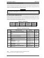
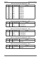
1.2.2 Printing Specifications
1 original+ 3copies
●
Copy capability
●
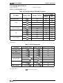
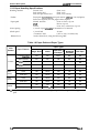
Print speed and printable columns
Table 1-4 Print Speed and Printable Columns
Print Speed (cps)
Print Mode
High-speed draft
Draft
Draft condensed
LQ
LQ Condensed
Character Pitch
Printable Columns
Normal
copy
10 cpi
136
300
244
10 cpi
136
275
183
12 cpi
163
330
220
15 cpi
204
413
275
17 cpi
233
236
157
20 cpi
272
275
183
10 cpi
136
92
61
12 cpi
163
110
73
15 cpi
204
138
92
17 cpi
233
157
105
20 cpi
2
183
122
7
2
. Resolution
Table 1-5 Print Resolution
Print Mode
Horizontal Density
High-speed draft
90 dpi
180 dpi
No
Draft
120 dpi
180 dpi
No
Draft condensed
240 dpi
180 dpi
No
LQ
360 dpi
180 dpi
No
60,80, 90, or 120 dpi
60 dpi
Yes
120 or 240 dpi
60 dpi
No
60,90, 120, or 180 dpi
180 dpi
Yes
360 dpi
180 dpi
No
180 or 360 dpi
180 or 360 dpi
Yes
8 pin bit image
24 pin bit image
.
Raster graphics
●
Acoustic noise
Rev.A
Vertical Density Adjacent Dot Printed?
51 dB (A), 1S0 7779 pattern
1-5
LQ-2070 Service Manual
Product Description
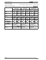
1.2.3 Paper Handling Specifications
●
Friction feed
Push tractor feed
Push and pull tractor feed
Feeding method
(front, rear)
(front, rear)
(front, rear, bottom)
. Feeder
Front push tractor(option), mar push tractor, CSFbin 1 /bin 2 (Option)
Pull tractor (Option) and roll paper holder (Option)
. Paper path
Manual insertion
CSF
Tractor
Front or rear in, top out
Rear in, top out
Front, rear, or bottom in, top out
●
Line spacing
1/6 inch or programrnable in increments of 1/360 inch.
●
Feed speed
1/6 inch feed
Continuous feed
45 msec
0.127 m /see ( 5.0 inches/see)
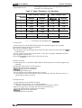
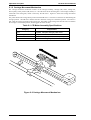
Set the release lever, using the following table.
. Release lever
Table 1-6 Paper Path and Paper Types
Paper Types
Lever
Position
Friction
Rear
tractor
Front
tractor
Full
release
Paper Entrance
Single Sheet
Labels
Card Stock I
Envelopes
Multipart
Roll Paper
Front insedion
OK
NO
OK%
OK
NO
Rear insertion
OK
NO
OK
OK
NO
CSF bin 1
OK
NO
OK
OK
NO
CSF bin 2
OK
NO
NO
NO
NO
Roll paper holder
NO
NO
NO
NO
OK
Push
OK
OK%
NO
OK
NO
Push-pull
OK
OK%
NO
OK
NO
Push
OK
OK%
NO
OK
NO
Push-pull
OK
OK%
NO
OK
NO
Pull (front bottom)
OK
OK
NO
OK
NO
Pull (rear)
OK
OK X
NO
OK
NO
% This symbol after “OK” means you need to check the paper type before using it with this paper
path.
1-s
Rev.A
Product Description
LQ-2070 Service Manual
Set the paper thickness lever to the appropriate position, as
indicated in the following table.
. Paper thickness lever
Table 1-7 Paper Thickness Lever Positions
Paper Thickness ( inches)
Paper Thickness (mm)
Lever Position
Minimum
Maximum
Minimum
Maximum
o
0.0024
0.0047
0.065
0.12
1
0.0047
0.0075
0.12
0.19
2
0.0075
0.0102
0.19
0.26
3
0.0102
0.0126
0.26
0.32
4
0.0126
0.0142
0.32
0.36
5
0.0142
0.0157
0.36
0.40
6
0.0157
0.0205
0.40
0.52
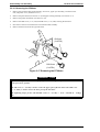
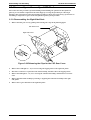
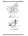
—–-——— Precautions for Handling Paper
1. Friction feed
. Set the release lever to the FRICTION position and install the paper eject assembly
● Load paper from the front or top entrance.
● Do not use continuous paper.
. Do not perform any reverse paper feeds within the top 8.5 mm (0.33 inch) and bottom 22 mm
(0.87 inch) area.
. Do not perform reverse feeds greater than 1/6 inch after the paper endhasbeen detected.
● Use the paper-tension unit.
● Insert the multipart cut sheet forms only from the front.
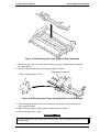
2. Push tractor feed
. Set the release lever to the REAR PUSH/FRONT PUSH position and install the paper eject
assembly.
● Load paper from the rear or front entrance.
● Release the friction feed mechanism.
. Multipart paper must be carbonless.
● Use the paper-tension unit.
. Do not perform reverse feeds greater than 1/6 inch.
. Do not perform reverse feeds after the paper end has been detected, because accuracy of
paper feeding cannot be assured.
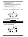
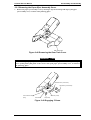
3. Pull tractor feed
. Set the release lever to the PULL position.
● Load paper from the front, rear, or bottom entrance.
(The front or bottom entrance is recommended for thick paper or labels.)
● Remove the paper eject assembly and attach the pull tractor unit.
. Insert paper from either from the front or bottom.
. Multipart paper must be carbonless.
. Do not perform reverse feeds.
Rev.A
1-7
LQ-2070 Service Manual
Product Description
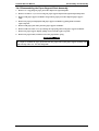
4. Push-pull tractor feed
release lever to the REAR PUSH/FRONT PUSH position.
Load paper from the front or rear entrance.
● Remove the paper eject assembly and attach the pull tractor unit.
● Remove any slack in the paper between the platen and pull tractor.
. Precisely adjust the horizontal position of the pull tractor and push tractor.
. Multipart paper mustbe carbonless.
. Do not perform reverse feeds greater than 1/6 inch.
. Do not perform reverse feeds after the paper end has been detected.
Set the
●
●
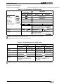
1.2.4 Paper Specifications
This section describes the printable area and types of paper that can be used in this printer.
Cut Sheets
●
The following table shows specifications for cut sheets.
Paper/ media specifications
Table 1-8 Specifications for Cut Sheets (Single Sheet, Not Multipart)
Rear Entry
Front Entry
Minimum
Maximum
Minimum
Maximum
Width
101 mm (4.0”)
420 mm (1 6.5”)
101 mm (4.0”)
420 mm (16.5”)
Length
147 mm (5.8”)
420 mm (16.5”)
101 mm (4.0”)
420 mm (16.5”)
0.065 mm(O.0025”)
0.14 mm (0.0055”)
0.065 mm(O.0025”)
0.14 mm (0.0055”)
52.3 g/m2 (14 lb)
90 g/m2 (24 lb)
52.3 g/m2 (14 lb)
90 g/m2 (24 lb)
Thickness
Weight
I
I
Plain paper, recycled paper.
Not curled, not folded, or not crumpled.
Quality
Plain paper, recycled paper.
Not curled, not folded, or not crumpled.
Table 1-9 Specifications for Cut Sheets (Multipart)
I
I
Front Entry
Rear Entry
Minimum
Maximum
Minimum
Maximum
Width
101 mm (4.0”)
420 mm (1 6.5”)
101 mm (4.0”)
420 mm (16.5”)
Length
147 mm (5.8”)
420 mm (16.5”)
101 mm(4.0”)
420 mm (16.5”)
Copies
1 original+ 3 copies
1 original+ 3 copies
Total
thickness
0.12 mm (0.0047”)
0.32 mm (0.013”)
W e i g h t %
I 40g/m2(121b)
Quality
Plain paper, recycled paper.
Not curled, not folded, or not crumpled.
Plain paper, recycled paper.
Not curled, not folded, or not crumpled.
Binding
A line of glue at the top or one side of the
form.
A line of glue at the top of the form.
I
58 g/m2 (15 lb)
0.12 mm (0.0047”)
I
40 g/m2 (12 lb)
0.32 mm (0.013”)
I
58 g/m2 (15 lb)
% This weight is for one sheet of the multipart form.
1-8
Rev.A
LC?-2070 Service Manual
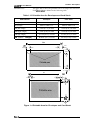
●
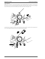
Printable area
Product Description
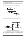
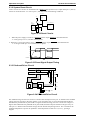
Figure 1-3 shows the printable area for cut sheets. The table
b;low defines the abbreviations used in the figure.
Table 1-10 Printable Area for Cut Sheets
Abbreviations
Single Sheet
Multipart
PW (width)
Refer to Table 1-8.
Refer to Table 1-9.
PL (length)
Refer to Table 1-8.
Refer to Table 1-9.
LM (left margin)
3 mm (0.12”) or more
(PW ~ 364 mm (14.33”))
25 mm (0.98”) or more
(PW = 420 mm (16.5”))
3 mm (0.1 2“) or more
(PW <364 mm (14.33”))
25 mm (0.98”) or more
(PW = 420 mm (16.5”))
RM (right margin)
3 mm or more
(PWs 364 mm (14.33”))
25 mm (0.98”) or more
(PW = 420 mm (16.5”))
3 mm or more
(PW S 364 mm (14.33”))
25 mm (0.98”) or more
(PW = 420 mm (16.5”))
TM (top margin)
4.2 mm (0.17”) or more
4.2 mm (0.17”) or more
BM (bottom margin)
4.2 mm (0.17”) or more
4.2 mm (0.1 7“) or more
I
———
TM
7
——?
PL
J
———
BM
} t
— ——— —
?
Figure 1-3 Printable Area for cut Sheets ‘
Rev.A
1-9
LQ-2070 Service Manual
Product Description
Envelopes and Card Stock
●
The following tables gives specifications for envelopes and card stock.
Paper/media specifications
Table 1-11 Specifications for Envelopes
Rear Entry
Front Entry
No. 6
envelopes
I
---
Width
Maximum
Minimum
Maximum
Minimum
166 mm (6.5”)
Length
*
--
92 mm (3.6”)
!!5L_E&
---
240 mm (9.5”)
..-
104 mm (4.1”)
Total thickness
---
....
---
Quality
0.52 mm (0.020”)
Differences in thickness in the printable
area must be within 0.25 mm (0.0098”).
.-.
Weight
0.16 mm (0.0063”)
....
45g/m2(12 lb)
91 g/m2 (24 lb)
Bond paper, plain paper, or airmail.
No glue at the flap.
Not curled. not folded. or not C~MDled.
....
% Printing on envelopes is available only at normal temperatures and humidity.
% Insert envelopes from the rear entrance only.
X Insert the longer side of the envelope horizontally.
Table 1-12 Specifications for Card Stock
Front Entry
Rear Entry
Minimum
Maximum
Minimum
Maximum
Width
105 mm (4.13”)
148 mm (5.83”)
105 mm (4.1 3“)
148 mm (5.83”)
Length
148 mm (5.83”)
148 mm (5.83”)
105 mm (4.13”)
148 mm (5.83”)
Thickness
Weight
Quality
0.22 mm (0.0087”)
0.22 mm (0.0087”)
192 g/m2 (51 lb)
192 g/m2 (51 lb)
Plain paper, recycled paper.
Not curled, not folded, or not
crumpled.
Plain paper, recycled paper.
Not curled, not folded, or not
crumpled.
% Printing on card stock is available only at normal temperatures and humidity.
* When the longer side of an A6 card is to be inserted horizontally, insert it from the rear entrance.
1-1o
Rev.A
Product Description
LQ-2070 Service Manual
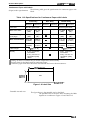
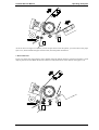
●
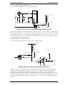
The figure below shows the printable area for envelopes and card stock.
Each ~bbreviation is defined-in the following table. -
Printable area
Table 1-13 Printable Area for Envelopes and Card Stock
Envelopes
Card Stock
PW (width)
Refer to Table 1-11.
Refer to Table 1-12.
PL (length)
Refer to Table 1-11.
Refer to Table 1-12.
LM (left margin)
3 mm (0.1 2“) or more
3 mm (0.12”) or more
RM (right margin)
3 mm (0.12”) or more
3 mm (0.12”) or more
TM (top margin)
4.2 mm (0.17”) or more
4.2 mm (0.17”) or more
4.2 mm (0.17”) or more
4.2 mm (0.1 7“) or more
Abbreviations
BM (bottom
margin)
.
Pw
t
\
>1
-%
-–wI
\\
TM ‘
———
?
-–#-
K,
I
‘>; LM ~–
I
Pw
,
>1
–>i RMk+
‘
,
I
.—J—
TM
———
+
+
———
BM
.———
+
Figure 1-4 Printable Area for Envelopes and Card Stock
Rev.A
1-11
LQ-2070 Service Manual
Product Description
Continuous Paper
●
The following table gives specifications continuous paper.
Paper/media specifications
Table 1-14 Specifications for Continuous Paper (Single Sheet and Multipart)
Front Entry
Width
Length
Copies
Total thickness
Weight
(not multipart)
Weight (one sheet
of a multipart form)
Rear Entry
Bottom Entry
Minimum
Maximum
Minimum
Maximum
Minimum
Maximum
101 mm
406 mm
101 mm
406 mm
101 mm
406 mm
(4.0”)
(16”)
(4.0”)
(16”)
(4.0”)
(16”)
101 mm
(4.0”)
559 mm
(22”)
101 mm
559 mm
101 mm
559 mm
(4.0”)
(22”)
(4.0”)
(22”)
1 original + 3 copies
1 original+ 3 copies
1 original + 3 copies
0.065 mm
(0.0025”)
0.32 mm
0.065 mm
0.32 mm
0.065 mm
0.32 mm
(0.013”)
(0.0025”)
(0.013”)
(0.0025”)
(0.013”)
52.3 g/m2
(14 lb)
82 g/m2
(22 lb)
52.3 g/m2
(14 lb)
82 g/m2
(22 lb)
52.3 g/m2
(14 lb)
82 g/m2
(22 lb)
40 g/m2
(12 lb)
58 g/m2
(15 lb)
40 g/m2
58 g/m2
40 g/m2
58 g/m2
(12 lb)
(15 lb)
(12 lb)
(15 lb)
Types of paper
Plain paper.
Recycled paper.
Carbonless multipart.
Plain paper.
Recycled paper.
Carbonless multipart.
Plain paper.
Recycled paper.
Carbonless multipart.
Binding
Dots of glue or paper
staples (both sides).
Dots of glue or paper
staples (both sides).
Dots of glue or paper
staples (both sides).
1-12
Rev.A
Product Description
LQ-2070 Service Manual
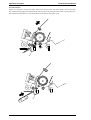
●
The figure below shows the printable area for continuous paper.
Each abbreviation is defined in the following table.
Printable area
Table 1-15 Printable Area for Continuous Paper
I
I
Abbreviations
Continuous Paper
PW (width)
Refer to Table 1-14.
PL (length)
Refer to Table 1-14.
LM (left margin)
13 mm (0.51”) or more
RM (right margin)
13 mm (0.51”) or more
TM (top margin)
4.2 mm (0.17”) or more
BM, (bottom margin)
4.2 mm (0.1 7“) or more
Pw
<
I
I
I
t
– – – – – – – – –
I 0
–––l–-
4
———
BM
—
—)
T
Figure 1-5 Printable Area for Continuous Paper
Rev.A
1-13
LQ-2070 Service Manuai
Product Description
Continuous Paper with Labels
●
The following table gives the specifications for continuous paper with
labels.
Paper/media specifications
Table 1-16 Specifications for Continuous Paper with Labels
Rear Entry
Front Entry
Minimum
Label size
Maximum
Minimum
Base sheet length
(one page)
Base sheet thickness
Total thickness
101 mm
406 mm
(4.0”)
(16”)
101 mm
(4.0”)
559 mm
(22”)
0.07 mm
0.09 mm
(0,0028”)
(0.0035)
0.16 mm
(0.0063”)
(0.0075”)
Label weight
-
Minimum
Maximum
See the figure below
-
...
101 mm
406 mm
(4.0”)
(16”)
101 mm
559 mm
‘-
‘--
(4.0”)
(22”)
0.07 mm
0.09 mm
‘-
‘--
(0.0028”)
(0.0035”)
0.16 mm
0.19 mm
‘--
‘-
(0.0063”)
(0.0075”)
0.19 mm
-..
68 g/m2 (17 lb)
. A very continuous
form labels
. A very mini-line or
equivalent quality
labels
Quality
Maximum
---
See the figure below
Base sheet width
Bottom Entry
-
68 g/m2 (17 lb)
. Avery continuous
form labels
. Avery mini-line or
equivalent quality
labels
.-.
% Printing on labels is available only at normal temperatures and humidity.
* The base sheet for the labels must be continuous paper.
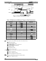
% Continuous paper with labels should be inserted from the front or bottom entrance.
<
2.5inch (63.5mm) min.
>
—
T
15/16inch
(23.6mm)
min.
Label
RO.linch (2.5mm) min.
Figure 1-6 Label Size
. Printable size and area
1-14
The figure above is the printable size for the labels.
The printable area for the base sheet containing the labels
depends on conditions in Figure 1-5 and Table-1-15.
Rev.A
Product Description
Lt2-2070 Service Manual
Roll Paper
Note:
Roll paper is not available in all models, and not available in the U.S.
. Paper/media specifications
The following table shows specifications for roll paper.
Table 1-17 Specifications for Roll Paper
I
I
I
Rear Entry
Front Entry
Maximum
Minimum
Maximum
Minimum
Width
---
216 mm (8.5”)
Length
.-.
.-.
Thickness
---
---
0.07 mm (0.0028”)
0.09 mm (0.0035”)
Weight
..-
---
52.3 g/m2 (14 lb)
82 g/m2 (22 lb)
Quality
●
Plain paper, recycled paper.
Not curled. not folded, or not crumpled.
---
I
Figure 1-7 gives the printable area for roll paper.
Each abbreviation is defined in the following table.
Printable area
Table 1-18 Printable Area for Roll Paper
Roll Paper
Abbreviations
PW (width)
See Table 1-17.
PL (length)
See Table 1-17.
LM
3 mm (0.12”) or more
RM
3 mm (0.12”) or more
TM
4.2 mm (0.17”) or more
BM
4.2 mm (0.17”) or more
—
Pw
&
II
I
I
1
1
-LTM
PL
Figure 1-7 Printable Area for Roll Paper
Rev.A
,,
1-15
LQ-2070 Service Manuai
Product Description
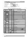
1.2.5 Ribbon Specifications
Table 1-19 Statistics on the Ribbon
Specification
Item
Type
Fabric
Color
Black
Ribbon life
8 million characters (draft, 10 cpi, 48dotcJ character)
Dimension
506.0 mm (W) x 123.5 mm (D) x 23.0 mm (H)
19.92” (W) X 4.86” (D) X .91 “ (H)
1.2.6 Electrical Specifications
Tables 1-20 and 1-21 provide statistics on electrical ratings and consumption.
Table 1-20 Electrical Specifications for the 120 V Version
Item
Specifications
Rated voltage
I 120VAC
Input voltage range
I 103.5to 132VAC
Rated frequency range
I 50t060 Hz
Input frequency range
49.5 to 60.5 Hz
Rated current
1.0 A (max. 2.4A)
Power consumption
Approx. 34 W (self-test in draft mode at 10 cpi)
Insulation resistance
10 MQ min. (between AC line and chassis, 500VDC)
Dielectric strength
I
1000 VAC rms. 1 min. or
1200 VAC rms. 1 sec. (between AC line and chassis)
Table 1-21 Electrical Specifications for the 220/240 V Version
Item
Rated voltage
220 to 240 VAC
Input voltage range
198 to 264 VAC
Rated frequency range
I 50to 60 Hz
Input frequency range
49.5 to 60.5 Hz
Rated current
0.5 A (maximum 1.2A)
Power consumption
1-16
Specifications
I Approx. 34 W (self-test in draft mode at IOcpi)
Insulation resistance
10 MQ min. (between AC line and chassis, 500VDC)
Dielectric strength
1500 VAC rms. 1 min. (between AC line and chassis)
Rev.A
Product Description
LQ-2070 Service Manual
1.2.7 Environmental Conditions
Table 1-22 explains the conditions the printer requires during operation and when not operating,
Table 1-22 Environmental Requirements
Item
Specifications
I
Temperature
5 to 35° C/41 to 95° F ( operating %1)
15to 25° C/59 to 77° F (operating X1,X 2)
-30 to 60° C/-22 to 140° F (non-operating)
Humidity
10 to 80 % RH (operating M 1)
30 to 60 ?’o RH (operating X 1,X 2)
O to 85 % RH (non-operating %1)
Resistance to shack
1 G, within 1 ms (operating)
2 G, within 2 ms (non-operating %3)
Resistance to vibration
0.25 G, 10 to 55 Hz (operating )
0.50 G, 10 to 55 Hz (non-oDeratina % 3)
% 1: Without condensation.
*2: During printing on multipart paper, envelopes, card stock, or labels.
%3: In shipment container.
1.2.8 Reliability
Table 1-23 gives maximum life and usage specifications.
Table 1-23 Reliability Statistics
Item
Specification
1
Total print volume
MTBF
Printhead life
Ribbon life
6 million lines (except printhead)
6000 power on hours (POH)
1
I 200 million strakes/wire
I
8 million characters
1.2.9 Safety Approvals
Table 1-24 provides information about the safety approvals the printer has met.
Table 1-24 Safety Information for Printer Models
120 v
I
230 V
Safety Standards
UL1950 with D3
CSA C22.2 N0,950 with D3
EMI
FCC parl 15 subpart B class B EN55022 (CISPR pub.22)
CSA CI08.8
class B
Rev.A
EN60950 (TuV. SEMKO,
DEMKO, NEMKO, FIMKO )
1-17
LQ-2070 Service Manual
Product Description
1.2.10 CE Marking
The following table lists CE marking information.
Table 1-25 CE Marking
Low Voltage Directive 73/23 / EEC
EN60950
EMC Directive 89/336/ EEC
EN55022 class B
EN50082-1 , IEC801-2
IEC801-3 , IEC801-4
EN45501
Non-Automatic Weighing Instruments Directive 90/384/EEC
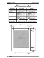
1.2.11 Physical Specifications
Table 1-26 provides printer dimensions and weight.
Table 1-26 Physical Specifications
Dimensions
Weight
639 mm (W) x402 mm (D) x 257 mm (H)
25.16” (W) X 16.14” (D) X 10.12” (H)
I
I Approx. 13 kg (28.66 lb)
1.2.12 Cut Sheet Feeder Specifications
This printer has two CSF options: a high-capaaty CSF and a 2nd bin CSF. The high-capacity CSF
has special a paper-feed motor to load the paper quickly. The 2nd bin CSF can be connected to the
high-capacity CSF to allow them to be used as a double bin CSF. The following table provides the
specifications for these CSF options.
. Hopper capacity
Table 1-27 Hopper Capacity
CSF Bin 1
Single sheets
150 sheets (%1) / 110 sheets (% 2)
185 sheets (%3) / 135 sheets (% 4)
CSF Bin 2
50 sheets (~ 1 ) / 50 sheets (% 2)
60 sheets (~ 3) / 60 sheets (3$ 4)
Envelopes
25 sheets (X 5)
30 sheets (% 6)
-..
Card stock
50 sheets (% 7)
-..
Multipart paper
40 sheets (% 8)
---
% 1 : Plain paper (weight: 82 g/m2, 22 lb) or recycled paper, except for A3-size paper.
%2: Plain paper (weight: 82 g/m2, 22 lb) or recycled paper, A3 paper.
%3: Plain paper (weight: 64 g/m2, 17 lb), except for A3 paper.
*4: Plain paper (weight: 64 g/m2, 17 lb), A3 paper.
X 5 : Envelopes (weight: 91 g/m2, 24 lb)
~ 6: Envelopes (weight: 45 g/m2, 12 lb)
%7: Card stock (weight: 192g/m2,51 lb; thickness: 0.22 mm, O.0087”)
3+8: 1 original+ 5 copies (thickness: 0.36 mm, 0.0142”)
1-18
Rev.A
Product Description
LQ-2070 Service Manual
. Stacker capacity
Table 1-28 Capacity of the Stacker
CSF Bin 1
CSF Bin 2
Single sheets
140 sheets (+$ 1)
100 sheets (~ 2)
----
Envelopes
15 sheets (% 3)
28 sheets (% 4)
----
Card stock
30 sheets (% 5)
----
Multipart
36 sheets (3$6)
... -
%1: Single sheets (weight: 82 g/m2i 22 lb), except for A3 paper
*2: Single sheets (weight: 82 g/m ,22 lb), A3 paper
*3: Envelopes (weight: 91 g/m2, 24 lb)
*4: Envelopes (weighti 45 g/m2, 12 lb)
*5: Card stock (weight: 192 g/m2, 51 lb; thickness: 0.22 mm, 0.0087”)
3%6: 1 original+ 5 copies (thickness: 0.36 mm, 0.0142”)
. Reliability
2 x 10⁵ cycles
MCBF:
. Environmental conditions
Table 1-29 Environmental Conditions
Temperature
Humidity
Operating
Non Operating
5 to 35° c (41 to 95° l=)
–30 to 60° C (-22 to 140° F)
10 to 80% RH (%1, X 3)
30 to 60% RH (%2, X 3)
O to 85% RH (%3)
Single sheets (plain, 64 g/m2 < weight <82 g/m2 ;/17 lb e weight <22 lb)
Single sheets (plain, weight< 64 g/m2, 82 g/m2 < weight/weight < 171b, 22 lb < weight)
Single sheets (recycled), multipart, envelopes, and card stock
Without condensation
Rev.A
1-19
LQ-2070 Service Manual
Product Description
1.3 Firmware Specifications
This section provides detailed information about LQ-2070
firmware.
1.3.1 Control Codes and Fonts
●
Control codes
ESC/P2 and IBM 2390/2391 plus emulations.
●
Typefaces
Bitmap fonts
EPSON Draft
EPSON Roman
EPSON Saris Serif
EPSON Courier
EPSON Prestige
EPSON Script
EPSON OCR-B
EPSON Orator
EPSON Orator-S
EPSON Script C
10 cpi, 12 cpi, 15 cpi
10 cpi, 12 cpi, 15 cpi, proportional
10 cpi, 12 cpi, 15 cpi, proportional
10 cpi, 12 cpi, 15 cpi,
10 cpi, 12 cpi
10 cpi
10 cpi
10 cpi
10 cpi
Proportional
Scalable font
EPSON Roman
EPSON Saris Serif
EPSON Roman T
EPSON Saris Serif H
10.5pt.,
10.5pt.,
10.5pt.,
10.5pt.,
8pt.-32pt. (every 2 pt.)
8pt.-32pt. (every 2pt.)
8pt.-32pt. (every 2pt.)
8pt.-32pt. (every 2pt.)
Bar code fonts
EAN-13, EAN-8, Interleaved 2 of 5, UPC-A, UPC-E, Code 39
Code 128, POSTNET
14 countries
U.S.A., France, Germany, U.K., Denmark 1, Sweden, Italy,
Spain l, Japan, Norway, Denmark2, Spain2, Latin America,Korea,Legal
International character sets
●
The standard version has 11 character tables and the NLSP version has 20
character tables, as shown in the following table.
. Character tables
Table 1-30 Character Tables
Character Tables
Version
PC-850 (Multilingual)
pC-437 (U.S., Standard Eur.)
Italic
I
Standard
Version
PC-860 (Portuguese)
PC-861 (Icelandic)
PC- 863 (Canadian-French)
PC-865 (Nordic)
Abicomp
BRASCII
I Roman8
] ISOLatin 1
PC-855 (Cynllic)
I PC-852 (East Europe)
I
PC-857 (Turkish)
PC-869 (Greek)
MAZOWAI (Poland)
PC-437 Greek
NLSP Version
I
I
I
1-20
ISO 8859-7 (Latin/Greek)
I
Estonia (Estonia)
ISO Latin IT (Turkish)
I PC-853 (Turkish)
I
PC-866 (Russian)
Code MJK (CSFR)
d
Bulgaria (Bulgarian)
ISO Latin 2
PC-744(LST 1283:1993)
)
I
PC-866 LAT (Latvia)
PC-850 (Multilingual)
PC- 437 (US, Standard Eur.)
Italic
I
I
PC-864 (Arabic)
Rev.A
Product Description
LQ-2070 Service Manual
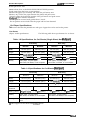
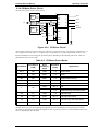
1.3.2 Interface Specifications
This printer provides a bidirectional 8-bit parallel interface and a Type B optional interface slot,
standard.
1.3.2.1 Parallel Interface (Fotward Channel)
●
Transmission mode
8-bit parallel, IEEE-P1284, compatibility mode
●
Adaptable connector
●
Synchronization
57-30360 (Amphenol) or equivalent
STROBE P1.lk
BUSY and ACI@lLG signals
. Handshaking
●
‘ITL compatible (IEEE-P1284 level 1. device)
Signal level
Table 1-31 Pin Assignments for Forward Channel
Pin
No.
Signal
Name
Return
GND pin
In IOut
Function Description
1
STROBE
19
In
Strobe pulse. Input data is latched at falling edge of the signal
2
DATA1
20
In
Parallel input data to the printer
3
DATA2
21
In
bit 1
4
DATA3
22
In
bit 2
5
DATA4
23
In
bit 3
6
DATA5
24
In
bit 4
7
DATA6
25
In
bit 5
8
DATA7
26
In
bit 6
9
DATA8
27
In
bit 7: MSB
10
ACKNLG
28
out
This signal (negative pulse) indicates the printer has received
data and is ready to accept more data.
11
BUSY
29
out
This signal’s HIGH level means the printer is not ready to
accept data.
PE
28
out
This signal’s HIGH level means the printer has a paper-out
error.
13
SLCT
28
out
Always HIGH when the printer is powered on.
14
AFXT
30
In
Not used.
31
M
30
In
This signal’s negative pulse initializes printer.
32
ERROR
29
out
36
SLIN
30
In
18
Logic H
----
out
This line is pulled up to + 5 V through 3.9KQ resistor.
35
+5V
----
Out
This line is pulled up to +5 V through 3.3KQ resistor.
17
Chassis
----
-–-
Chassis GND.
GND
----
---
Signal GND.
19-30
15,34
NC
----
---
Not connected.
, 12
16,33,
Rev.A
bit O: LSB
This signal’s LOW level means the printer is in an error state.
Not used.
1-21
Product Description
LC?-2070 Service Manual
DATA
‘T
R O B E
~tsetu~<
BUSY
1
tstb
!
p-r
I
&
!
treadv~l>
tbusy
ACKNLG
I
I
Figure 1-8 Data Transmission Timing
Table 1-32 Maximum and Minimum Timings for Data Transmission
Parameter
Minimum
Maximum
setup
500 nsec
-...
thold
500 nsec
-----
t stb
500 nsec
.....
tready
0
-...
tbusy
-..
500 nsec
treply
-..
-...
tack
500 nsec
10 ~
tnbusy
o
-...
tnext
o
-...
ttout
-..
120 nsec
ttin
-..
200 nsec
0 The BUSY signal is active (HIGH level) under the conditions below:
0 During data receipt.
0 If the input buffer is full.
0 If the INITsignal is active (LOW level).
0 During hardware initialization.
0 In self-test mode.
0 In adjustment mode.
0 In default-setting mode.
0 The ERROR signal is active (LOW level) under the conditions below:
0 If there is a fatal error.
0 If there is a paper-out error.
0 If the cover is open (cover open error).
. PE signal is active (HIGH level) under the conditions below:
0 If there is a paper-out error.
1-22
Rev.A
Product Description
LQ-2070 Service Manual
1.3.2.2 Parallel Interface (Reverse Channel)
IEEE-P1284 nibble mode
Transmission mode
. Adaptable comector
● Synchronization
57-30360 (Anphenol) or equivalent
Refer to the IEEE-P1284 Specification
. Handshaking
Refer to the IEEE-P1284 Specification
●
●
TILcompatible (IEEE-P1284 level 1 device)
Signal level
Refer to the specification
. Data transmission timing
Table 1-33 Pin Assignments for Reverse Channel
Pin
No,
Signal
Name
Retl$yn@JD
In/Out
1
HostClk
19
In
Host clock signal.
2
DATA1
20
In
Parallel input data to the printer
3
DATA2
21
In
bit 1
4
DATA3
22
In
bit 2
5
DATA4
23
In
bit 3
6
DATA5
24
In
bit 4
7
DATA6
25
In
bit 5
8
DATA7
26
In
bit 6
9
DATA8
27
In
bit 7: MSB
10
PtrClk
28
out
Printer clock signal.
11
PtrBusy I
DataBit-3, 7
29
out
Printer busy signal and reverse channel transfer of data
bits 3 or 7
12
AckDataReq/
DataBit-2, 6
28
out
Acknowledge data request signal and reverse channel
transfer of data bits 2 or 6
13
Xflag /
DataBit-l, 5
28
out
X-flag signal and reverse channel transfer of data bits 1
or 5
14
HostBusy
30
In
Host busy signal.
31
m
30
In
Not used.
32
DataAvail /
DataBit-O, 4
29
out
36
1284-Active
30
In
18
Logic H
---
out
This line is pulled up to + 5 V through 3.3K Q resistor.
35
+5 v
-..
out
This line is pulled up to +5 V through 3.3K Q resistor.
17
Chassis
---
-—
Chassis GND.
16,33,
19-30
GND
-..
..-
Signal GND.
15,34
NC
-..
..-
Not connected.
Rev.A
Function Description
bit O: LSB
Data available signal and reverse channel transfer of
data bits O or 4
1284 active signal.
1-23
LQ-2070 Service Manual
Product Description
Extensibility request
●
●
00 H
Request nibble mode of reverse channel transfer.
04 H
Request device ID in nibble mode of reverse channel transfer.
Refer to the following descriptions:
Device ID
ESC/P2
The printer responds to the extensibility request in the affirmative, when
the request is 00 H or 04 H, which means:
[00 H][32 H] . . . . . . MFG: EPSON, CMD: ESCPC2-00, MDL: LQ-2070, CLS: PRINTER
IBM2391 ph.Is [00 H][33H] . . . . . . MGF: EPSON, CMD: PRPXL24-01, MDL: LQ-2070, CLS: PRINTER
1.3.2.3 Interface Selection
The printer has 2 interfaces: the parallel interface and Type B optional interface. These interfaces
are selected manually in default setting mode or selected automatically.
●
Manual selection
One of 2 interfaces can be selected in default setting mode.
. Automatic selection
Automatic interface is enabled in default setting mode. In automatic interface mode, the printer is
initialized to the idle state, where it scans which interface is to be activated. The interface that
receives data first is selected. When the host stops data transfer, and the printer is in standby for a
number of seconds specified in default setting mode, the printer returns to the idle state. As long as
the host sends data or the printer interface is busy, the selected interface remains active.
. Interface state and interface selection
When the parallel interface is not selected, that interface goes into a busy state. When the Type B
serial interface card is installed and it is not selected, the interface sends an XOFF code and sets the
DTR signal to MARK. When the optional interface is not selected, the printer sends disable
commands to the optional interface. When the printer is initialized or returned to the idle state, the
parallel interface gcxx into the ready state, the serial interface sends an XON code and sets the DTR
signal to SPACE, and the printer sends an enable command to the optional interface. Remember
that interrupt signals, such as the INIT signal on the parallel interface, are not effective unless that
interface is selected.
1.3.2.4 Prevention Hosts from Data Transfer Time-out
Generally, hosts abandon data transfer to peripherals when the peripheral is in the busy state for
dozens of seconds continuously. To prevent hosts from this kind of time-out, the printer receives
data very slowly, several bytes per minute, even if the printer is in the busy state. This slowdown is
started when the rest of the input buffer becomes several hundreds of bytes. Finally, when the
input buffer is full, the printer is in busy continuously.
1-24
Rev.A
Product Description
LQ-2070 Service Manual
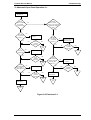
1.3.3 Paper Handling Sequence
In this section, paper handling firmware sequences are described in several cases.
●
Printer status
Printer is on line (not in the pause state).
No PE sensor detects that paper is loaded.
The release lever position is set to continuous paper.
Table 1-34 Paper Handling Sequence 1
Result
Occurrence
Print command sent
Continuous paper is loaded.
Pause button pressed
Printer enters pause state.
LF/FF button pressed
Continuous paper is loaded.
I
Continuous paper is loaded.
i
I No operation.
I
Load/Eject button pressed
I Micro Adjust ~button pressed
●
Micro Adjust ~ button pressed
No operation.
Release lever set to Friction
The paper path is changed for cut sheets.
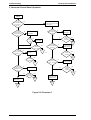
Printer status
The rear PE sensor detects that paper is loaded in the rear paper path.
The release lever is set to continuous paper.
Table 1-35 Paper Handling Sequence 2
Occurrence
Result
Pause button pressed
The printer goes off or on line.
LF/FF button pressed
The printer performs a line feed.
LF/FF button held down continuously
The printer performs a form feed after the line
feed.
Load / Eject button pressed
Paper is ejected to the rear paper park position.
Load /Eject button pressed and paper
advanced to skiR area
Paper is advanced to the nexl TOF position.
Micro Adjust ~ button pressed
The printer micro feeds paper forward.
Micro Adjust ~ button pressed
The printer micro feeds paper backward,
Release lever set to Friction
The beeper sounds.
Front paper end sensor detects that paper is
loaded in the front paper path.
The beeper sounds.
Rev.A
1-25
LQ-2070 Service Manual
Product Description
. Printer status
The front PE sensor detects that paper is loaded in the front paper path.
The release lever is set to continuous paper
Table 1-36 Paper Handling Sequence 3
Result
Occurrence
PAUSE button pressed
Printer goes off or on line.
LF/FF button rxessed
Printer Derforms a line feed.
LF/FF button held down continuously
The printer performs a form feed after the line
feed.
Paper is ejected to the front paper park position
Load / Eject button pressed
I
●
Load /Eject button pressed and the paper was
advanced to skip area
Paper is advanced to the next TOF position.
Micro Adjust button pressed
The printer micro feeds paper forward.
Micro Adjust ~ button pressed
The printer micro feeds paper backward.
Release lever was set to Friction
The beeper sounds.
Front paper end sensor detects that paper
was loaded in the rear paper path.
The beeper sounds.
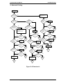
Printer status
Printer is on line ( not in the pause state).
No PE sensor detects that paper is loaded. ( The printer is set to CSF.)
The release lever is set to the Friction.
Table 1-37 Paper Handling Sequence 4
Occurrence
Result
Print command sent
The paper is loaded from the CSF.
Pause button pressed
Printer goes off line.
LF/FF button pressed
Paper is loaded from the CSF.
Load / Eject button pressed
Paper is loaded from the CSF.
Micro Adjust ? button pressed
No operation.
Micro Adjust ~ button pressed
No operation.
Release lever set to tractor position
The paper path is changed to tractor.
Rear/ Front paper end sensor detects that
paper is loaded in the rear or front paper path.
And, 3 seconds have passed.
The printer feeds paper.
Rear/ Front paper end sensor detects that
paper is loaded in the rear or front paper path.
And, Pause, LF/FF, or LOAD/EJECT button
was pressed.
Ignored.
1-26
Rev.A
Product Description
LQ-2070 Service Manual
●
Printer status
The rear PE sensor detects that paper is loaded in the rear paper path.
Release lever position is set to Fri&ion.
Table 1-38 Paper Handling Sequence 5
Result
Occurrence
Pause button pressed
Printer goes on or off line.
LF/FF button pressed
Printer performs a line feed.
LF/FF button held down continuously
Printer ejects paper forward after the line feed
(except with roll paper).
The printer performs a form feed after the line
feed (roll paper).
LF / FF button pressed, and paper is
advanced over the logical paper length.
Paper is ejeded forward (except with roll paper).
The printer petfonns a form feed (roll paper).
Load /Eject button pressed
Paper is ejected forward (except with roll paper).
The printer petforms a form feed (roll paper).
Micro Adjust ~ button pressed
The printer micro feeds paper forward.
Micro Adjust ~ button pressed
The printer micro feeds paper backward.
Release lever set to the tractor position
The beeper sounds.
Front paper end sensor detects that paper
was loaded in the rear paper path.
The beeper sounds.
. Printer status
Front PE sensor detects that paper is loaded in the rear paper path
The release lever position is set to Friction.
Table 1-39 Paper Handling Sequence 6
Trigger
Result
Pause button pressed
Printer goes on or off line.
LF/FF button pressed
Printer Derforms a line feed.
LF/FF button held down continuously
Paper is ejected forward after the line feed.
LF / FF button pressed, and paper advanced
more than the logical paper length.
The paper is ejected forward.
Load /Eject button pressed
The paper is ejected forward.
Micro Adjust ? button pressed
The printer micro feeds paper fotward.
Micro Adjust $ button pressed
The printer micro feeds paper backward.
Release lever set to tractor position
The beeper sounds.
Front paper end sensor detects that paper
was loaded on the rear paper path.
The beeper sounds.
Rev.A
I
1-27
LC?-2070 Service Manual
Product DescrhXion
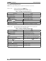
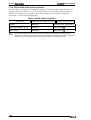
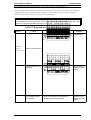
1.3.4. Paper Width (PW) Sensor Operation
The PW sensor is mounted on the ribbon mask holder to measure the paper width and detect the
top edge of the paper. However, in cases where print data is over the paper width, the image cut
function does not operate in all modes. This section describes when the image cut function is
operational, as shown in the following table.
Table 1-40 PW Sensor Operation
I
Paper Path
] P a p e r W i d t h M e a s u r e m e n t I Image Cut Function I
Friction
Measured
Executed (Only Copy Mode 2)
Push Tractor (Rear / Front)
Measured
Not Executed X 1
Pull Tractor
Measured
Not Executed % 1
*1:
The measured paper width value is used to estimate the printhead centering position.
When narrow continuous paper (fewer than 30 columns) is loaded, the printer changes the
centering position to the proper position, based on the measured paper width.
1-28
Rev.A
Product Description
LC?-2070 Service Manual
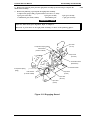
1.4 Operating Instructions
This section provides detailed information about the LQ-2070 control panel buttons and LEDs.
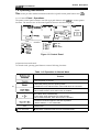
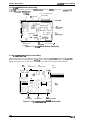
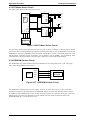
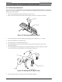
1.4.1 Control Panel Operations
The printer control panel contains 6 non-lock type push buttons and 8 LEDs for various printer
functions. The exterior view of the control panel is shown in the following figure.
~
$ ~..!!.
. . . . . . . . . . . . . . . . . . . ~comjen~ed,
~ ;-.
:;:
;:::.
Ii
❑ ❑ ❑ F~nt
Tear
.
o.ff.:/
:!:
:.
: ::,
: : :
:::
:;
. . . . . . . . . . . . . . . . . . , . . .:.. . . . . . . . . . . . . . . .,
o!
o
~
r
‘in w
F=F=
I
..................
: LF/FF
Font
. . . . . . . . . . . . . . . . . . -----~n ❑ ■ D r a f t
:0 ■ ❑ Roman
~ ❑ ■ 9 suns serif
; ■ ❑ ❑ Courier
: = ❑ ■ prestige
~~ ~ Script
; ■ ■ ■ others
.........................
Condensed
SS Paper Out
Operate
m
Load / Eject
. Tear
. . . . . . .Off
. . . . . /. . Bii
...
a LED Off
■ LED On
,4,
■ LED Blinks
Figure 1-9 Control Panel
●
Operation in normal mode
In normal mode, pressing panel buttons executes following functions:
Table 1-41 Operation in Normal Mode
I
Function
Turns the printer on and off.
Pause
~
Load / Eject
t---
. Alternates printing and non-printing states.
. Enables the micro adiust function. when held down for 3 seconds.
Loads or ejects paper
. Micro feeds forward, when that function is enabled.
●
Line feed, when pressed briefly.
. Form feeds, when held down for a few seconds.
. Micro feeds backward, when that function is enabled.
●
LF I FF
t==
I
Font
I Condensed
Rev.A
. Advances continuous paper to the tear-off position.
. Selects CSF bin 1 / 2 or card mode.
●
Selects font.
● Alternates condensed mode and non-condensed mode.
1-29
LQ-2070 Service Manual
Product Description
●
Operations at power on
Turning the printer on while pressing panel buttons executes the functions below:
Table 1-42 Operation at Power On
Function
Button
LQ self-test
Load / Eject
Draft self-test
LF I FF
Load I Eject and LF I FF
Condensed
Data dump
Default setting
Font and Tear Off / Bin
Clear EEPROM
Pause
Bi-d adjustment
Others
Not available
Font & Condensed
Quiet mode
.
. Operation in default setting mode
The buttons used in default setting mode areas follows:
Table 1-43 Operation at Default Setting Mode
Button
Function
Font
Selects the menu.
Tear Off / Bin
Others
Changes the setting
Not available
1.4.2 Status Codes Indicated by the LEDs and Beeper
Table 1-44 Indicators and Beeper
Pause
Off I Condensed
Paper Out Tear
Bin
Font
Beeper
Pause
On
--
.-
---
..-
...
Paper Out
On
On
---
..-
...
0 0 0
Paper Jam
On
Blinks
--
---
-..
Head Hot
Blinks
---
.-
.-.
...
On
Blinks
--
-..
---
Blinks
--
.-
...
...
0
Tear Off
..-
--
.-
.-,.
-..
0
Bin Selection
--
-.
.-
---
---
0
Condensed
---
--
.-
---
. .
0
Font Selection
---
-.
.-
..-
...
0
Blinks
Blinks
Blinks
Blinks
Blinks
Release Lever
Micro Adjust
Fatal Error
●
0 0 0 0
---
●
●
0000
0 0 0 0
m indicates the beeper sounds for 100 ms with an interval of 100 ms.
● indicates the beeper sounds for 500 ms with an interval of 100 ms.
— indicates that the LED or beeper is not used to indicate this status condition.
1-30
Rev.A
Product Description
LQ-2070 Service Manual
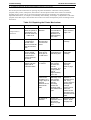
1.4.3 Micro Adjust Function
The micro adjust function lets you set the TOF and tear off positions. After the printer is put in this
mode, you can adjust the top of form (TOF) position up or down in increments of %16 inch by
pressing the LF/FF or Load/Eject button. The adjusted TOF position is saved to *e EEPROM. If
the printer is turned off, the setting is not cleared. The function is operational in the printer under
the following conditions and within the following area:
●
Conditions required for the adjustment
The TOF position can be adjusted under the following conditions:
1. The data buffer is empty and the printer is on line.
Paper is at the TOF position.
3. The Pause button is held down more than 3 seconds to put the printer in micro adjust mode.
2.
. Adjustable area
Micro adjust positions can be set within the following range from the top edge of the page:
4.2rnm- 8.5 mm ,8.5 mm + 1 inch
(0.16” - 0.33”, 0.33” + 24.5”)
1.4.4 Tear Off Function
The tear off function advances continuous paper to the tear off position when the Tear Off/ Bin
button is pressed. There are two modes for this function: auto tear off and manual tear off. The
teax off mode can be selected in the default setting mode. After the paper is tom off at the
perforation, it is fed back to the TOF position when any new print data is sent to the printer. The
tear off position is saved in the EEPROM, and if the printer is turned off, the setting is not cleared.
●
Conditions required for the adjustment
% Auto tear off function
0 Auto tear off has been set to ON in default setting mode.
0 The release lever has been set to Tractor. 0 The data buffer is empty, and the printer is on line.
0 More than 3 seconds have passed after tAe host computer finished transferring print data.
% Manual tear off function
0 Auto tear off has been set to OFF in default setting mode.
0 The release lever has been set to Tractor.
0 The data buffer is empty and the printer is on line, or the printer is off line.
0 The Tear Off button was pressed under all the conditions listed above.
. Paper handling with the tear off position
0 Pressing the Pause button with the printer offline feeds the paperback to the TOF
position for the next page and brings the printer back on line.
0 Pressing the Pause button with the printer on line feeds the paperback to the TOF
position for the next page and takes the printer off line.
0 Pressing the LF /FF button feeds the paperback to the TOFposition for the next
page and executes a line feed.
0 Pressing the Load /Eject button fee& the paperback to the TOF position for the next
page and ejects paper backward.
0 Pressing the Pause button more than 3 seconds puts the printer in micro adjust mode,
where you can adjust the tear off posit-ion by pressing the I-F /FF or Load/Eject button.
0 If the printer is turned off while in the tear off mode, the tear off position is saved, and
paper is fed back to the TOF position for the next page by turning on the printer, again.
Rev.A
1-31
LQ-2070 Sewice Manual
Product Description
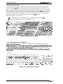
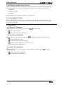
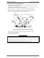
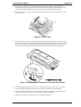
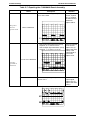
1.4.5 Self-test Function
Pressing the Load / Eject button while turning on the printer puts the printer in LQ self-test
mode. Pressing the LF/FF button while turning on the printer puts the printer in Draft self-test
mode. You can stop the self-test temporarily by pressing the Pause button, and you can exit the
self-test mode by turning off the printer. When pages are printed from the CSF, the first sheet is
used for scaling the sheet length. Then, the maximum number of printable lines is printed as the
bottom line of the sheet and this number is saved in non-volatile memory as the default page
length. Page lengths are saved individually when a dual-bin CSF is in use.
The self-test prints out the following:
0 The maximum number of printable lines (only oncutsheets from the CSF)
0 The pattern of characters shown in the figure below.
Roman
! “#$%&‘ ( )*+, -. /0 12345 6789: ; <--> ?@ ABCDEFGH I JKLMNopQRs’flJWxyz[ \ ] “ ‘ abcde fgh i j k lrnnopql
! II #$%&~ ( ) *+,-./0123456789:; <=> ?@ABCDEFGH I JKLMNOPQRSTU~XyZ [ \ 1“–~abcde f gh i j k lmnOPqr:
abcde f gh i .j k lrnnopq r.s 1
“#S%&’ ( )*+, -. /01 23456789 : ; <=> ?@ ABCDEFGH 1 jKLMNOpQRSTUVWXy Z [ \ ] “—~
#$%&’ ( )*+, -. / 0 1 2 3 4 5 6 7 8 9 : ;z=>?@-cDEFGHIJKLMNOpQRsTUmyZ[ \] ‘abcdefghi jklrnnopqrstl
$%&’ ( )*+, - . /012345 6789 : ; <=> ?@ ABCDEFGH I JKLMNOPQRSTUVWXYZ [ \ ] “ ‘abcdefgh i j k 1 mnopqrstul
%&$ ( )*+,-./0123456789:;<=> ?@ABCDEFGHI JKLMNOPQRSTUVWXYZI \ 1“–yabcde f ghi Jk ~ mnoPqrs tuv~
&’ ( ) *+, -./0 123456789: ; <=> ?@ABCDEFGHI JKLMNOPQRSTU~Xyz [ \ ] “–’ abcdef ghi jk lmnopqrs t uvw:
Saris S e r i f
‘ ( )*+, - ./01 23456789: ; <=> ?@ ABCDE FGH I J KLMNOPQRSTUVWXYZ [ \ 1‘— ‘ abcde f gh i 1 k 1 mnOPq r St uvwx !
( )•+,-./0123456789 : ; c=> ?.ABCDE FGH I J K LMNOPQRSTUVWXY Z [ \ 1‘— abc de f gh i 1 k 1 mnoPcl r St uvwx Y;
) ● + ,-. /01 23456789: ; :=>?eABCDEFGli 1 JKLMNOPQRSTUVWx YZ [ \ ] - ‘ abcdef gh i j k 1 mnopq rst uvwx YZ
● + ,- ,/@1234567B9: ;<=>?eABcDEFGHIJKLMNOPQRSTUVWXYZ[\]”–iabcdef9hi jklmnopqrstuvwxyz{
‘–’abcdefghi iklmnopqrstuvwxyz{ j
+,-./0123456789: ,.<=>?.ABcDEFGHIJKLMNOP(2RSTUVWXYZ[\]
, - . / 0 1 2 3 4 5 6 7 8 9 : ,.<=>?oABCDEFGHIJKLMNOPQRSTUVWXYZ[\] “–’abcdefghi jklmnopqrstuvwxyz (;)’
-./01234~6~89: ;<=>?eABcDEFGHIJKLMNoPoRsTuvwxYZ[\]
‘-’ abcdefghi jklmnopqrstuvwxyz( ~}-~
Figure l-lOSelf -test Printout
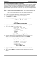
1.4.6. Hexadecimal Dump Function
Pressingthe Load/Ejectand LF/FFbuttons whiletumingon theprinterputs theprinterin
hexadecimaldump mode.In thismode,datareceivedisprinted outinhexadecimalforrna~along
with the corresponding ASCII characters. The function isuseful tocheckdata received from the
host. Ifareceivedcodeisnot aprintableASCIIcharacte~ the printer prints aperiod(.) inthe
ASCIIcolumn.Whenreceived dataremainsinthebuffe~ thatdataisprintedbypressingthe
Pausebutton.
Hex
Dump
1B401B2847o1OO 01 18285501oooA1B 5,5
01 IB 28 43 02 00 78 OF IB 28 63 04 00 00 00 00
00 16 2B 30 OA 09 OA OA OA OA OA IB 2E 01 14 14
18 00 06 81 00 81 00 81 00 81 00 81 00 81 00 81
00 81 00 81 00 81 00 81 00 81 00 81 00 81 00
00 81 00 81 00 81 00 81 00 81 00 81 00 81 00 81
00 81 00 81 00 81 00 81 00 ES 00 02 3F FF EO
00 03 03 CO 01 EO FE 00 02 03 80 IE FE 00 02
00 OE FA 00 07 03 CO 01 EO 00 00 OF CO 81
81
FE
IC
00
.@. (G. ...UU. ...U
.. (C. .X.. (C.....
..+0. . . . . . . . . . . .
...U.U.U.U.U.U.U
.u.u.u.u.ij.u.u.u
.U.u.u.u.u.u.u.u
.Li.u.ij.u.a..z a.. .L.aE...~.~.. .
E6 ... . . ~-~.--L~-~
Figure l-n Hexadecimal Printout
1-32
Rev.A
Product Description
LQ-2070 Service Manual
1.4.7 Default Setting Function
Pressing the Pitch button while turning on the printer puts the printer in default setting mode.
Some default printer settings can be changed in this operation. The method for setting defaults is
described in the instruction sheets, which are printed out immediately after you enter the mode.
You are asked to use three buttons (Font, Condensed, and Tear Off/ Bin) and watch six LEDs
(Condensed: 3 LEDs, Tear Off/Bin: 2 LEDs, and Pause: 1 LED) on the control panel. Refer the
instructions printed in default setting mode for the actual method used to set defaults.
1.4.8 EEPROM Clear Function
Pressing the Font and Tear Off /Bin buttons while turning on the printer resets the EEPROM to the
standard factory settings. This operation initializes the iterns below to the factory settings in the
right-hand column.
Table 1-45 EEPROM Initialization Settings
Setting
Font
Factory Default
I
I Roman
Condensed
10 CPI
Character Table
PC437
Page Format
( Tractor Rear/ Front)
Page Length:
11 inches
TOF Position:
8.5 mm (0.333 inches)
Bottom Margin : 11 inches
Page Format
(Friction , CSF Bin 1 / Bin 2,
Manual Feed Rear/ Front )
Page Length:
TOF Position:
Bottom Margin:
Print Direction
Bi-d
Auto LF
off
Auto Tear-Off
off
l-inch Skip
off
High Speed Draft
On
Input Buffer
On
BDC-ST Reply
off
l/F Selection
Auto l/F Mode
Auto l/F Wait Time
10 sec.
Software
ESCIP2
Slashed Zero
off
Buzzer
On
Auto CR ( IBM Mode)
off
Adjust Tear-Off Position
O inch
Paper Conditions
Friction: Bin 1, Tractor: Tear-Off: Status Off
Rev.A
22 inch
8.5 mm (0.333 inch)
22 inches
1-33
Product Description
LQ-2070 Service Manual
1.4.9 Bidirectional Adjustment Function
Pressing the Pause button while turning on the printer puts the printer in bidirectional adjustment
mode. In this mode, you can adjust the bidirectional alignment for the following three modes:
1. Draft mode
2. Draft
copy mode
3. LQmode
For instructions on performing the adjustment, see Chapter 4.
1.4.10 Quiet Mode Function
Pressing the Font button while turning on the printer puts the printer in quiet mode. In this quiet
mode, the printing speed can be 1/2 slower than usual speed. This function does not remain after
the printer is turned off.
1.5 Initialization
1.5.1 Software Initialization
This initialization is activated by the control code ESC@?. This initialization:
0 Clears unprinted data.
0 Resets the printer’s setting defaults.
1.5.2 Operation Initialization
This initialization is activated by receipt of the ~ signal (negative pulse). This initialization:
Cl Clears the buffer of all data.
0 Cancels download character definition.
0 Puts the printer in standby state, if no errors occur.
0 Executes software initialization.
1.5.3 Power On Initialization
This initialization is activated by power on or by a cold-reset command (remote RS command).
This initialization
0 Initializes the printer mechanism.
0 Executes operation initialization.
1-34
Rev.A
LC?-2070 Service Manual
Product Description
1.6 MAIN COMPONENTS
The main components
of the LQ-2070 are designed for easy removal and repair.
The main components are:
0 C186 MAIN Board Assembly
0C166PSB/PSE Board Assembly (120 V/230V)
0 C165 PNL Bowd Assembly
0 Printer Mechanism
Cl HousingAssembly
The following figure shows the main components of the LQ-2070.
Rev.A
1-35
LQ-2070 Service Manual
Product Description
1.6.1 C186 MAIN Board Assembly
The C186 MAIN board consists of a TMP96C041AF CPU, an E05B13 gate array, a program/CG
ROM, a PS-IWM, an EEPROM, etc.
Head Driva
TRANSISTOR
ICI 1,14 PF Motor Driver
TEA3718SDP
IC 5 PS RAM
1
1
~n
D
.H
/
IC12
CR Motor Driver
SLA7024M
\
IC
8
EEPROM
‘CN2 for Option I I F
Figure 1-13 C186 MAIN Board Assembly
1.6.2 C166 PSB/PSE Board Assembly
These boardshave two AC input voltage ratings: 120VAC (C166PSB) and230VAC (C166PSE).
Both boards consist of a transformer, switcking FET, regulator IC, diode bridge, etc. The power
supply board provides +5 VDC and +35 VDC for the main board and printer mechanism.
/ -
F1
Q1
Pcl
IC52
Fuse
I
Switching FET
Photo Coupler
OP-amp
II
1.
w
‘CIkD
,
El
D
\
1/
/
/
DBI
-
C!!!!!;
o
o
r\
Diode Bridge
/
/
.-
0
n
A
r
Ti
Trensformaer
1
1
/
1/51
Switching Regulator
TL494CN
Figure 1-14 C166 PSB/PSE Board Assembly
1-36
Rev.A
Product Description
LQ-2070 Service Manual
1.6.5. Housing Assembly
This consists of printer cover assembly, edge guide assembly, upper housing, lower housing
assembly, etc.
Figure 1:17 Housing Assembly
1-38
Rev.A
CHAPTER 2
Operating Principles
Table of Contents
2.1 PRINTER MECHANISM OPERATION
2-1
2.1.1 Printing Mechanism . . . . . . . . . . . . . . . . . . . . . . . . . . . . . . . . . . . . . . . . . . 2-1
2.1.2 Carriage Movement Mechanism . . . . . . . . . . . . . . . . . . . . . . . . . . . . . . . . 2-2
2.1.3. Platen Gap Adjustment . . . . . . . . . . . . . . . . . . . . . . . . . . . . . . . . . . . . . . . 2-3
2.1.4 Paper Handling Mechanism . . . . . . . . . . . . . . . . . . . . . . . . . . . . . . . . . . . . 2-4
2.1.4.1 Release Lever. . . . . . . . . . . . . . . . . . . . . . . . . . . . . . . . . . . . . . . . . 2-4
2.1.4.2 Paper Advance Mechanism . . . . . . . . . . . . . . . . . . . . . . . . . . . . . . 2-5
2.1.5 Paper Paths . . . . . . . . . . . . . . . . . . . . . . . . . . . . . . . . . . . . . . . . . . . . . . . 2-11
2.1.6 Ribbon Advance Mechanism . . . . . . . . . . . . . . . . . . . . . . . . . . . . . . . . . . 2-16
2.2 POWER SUPPLY OPERATION
2-17
2.2.1 Power Supply Overview . . . . . . . . . . . . . . . . . . . . . . . . . . . . . . . . . . . . . . 2-17
2.2.2 Power Supply Circuit Operation . . . . . . . . . . . . . . . . . . . . . . . . . . . . . . . . 2-18
2.3 CONTROL CIRCUIT
2.3.1 Control Circuit Operation Overview . . . . . . . . . . . . . . . . . . . . . . . . . . . . .
2.3.2 System Reset Circuit . . . . . . . . . . . . . . . . . . . . . . . . . . . . . . . . . . . . . . . .
2.3.3 Printhead Driver Circuit . . . . . . . . . . . . . . . . . . . . . . . . . . . . . . . . . . . . . .
2.3.4 CR Motor Driver Circuit . . . . . . . . . . . . . . . . . . . . . . . . . . . . . . . . . . . . . .
2.3.5 PF Motor Driver Circuit . . . . . . . . . . . . . . . . . . . . . . . . . . . . . . . . . . . . . . .
2.3.6 EEPROM Control Circuit . . . . . . . . . . . . . . . . . . . . . . . . . . . . . . . . . . . . .
2.3.7 Sensor Circuits . . . . . . . . . . . . . . . . . . . . . . . . . . . . . . . . . . . . . . . . . . . . .
2-22
2-22
2-24
2-24
2-25
2-26
2-26
2-27
List of Figures
Figure 2-1. Principles of Printhead Operation . . . . . . . . . . . . . . . . . . . . . . . . . . . 2-1
Figure 2-2. Carriage Movement Mechanism. . . . . . . . . . . . . . . . . . . . . . . . . . . . 2-2
Figure 2-3. Platen Gap Adjust Lever . . . . . . . . . . . . . . . . . . . . . . . . . . . . . . . . . . 2-3
Figure 2-4. Release Sensor Switches . . . . . . . . . . . . . . . . . . . . . . . . . . . . . . . . . 2-4
Figure 2-5. Friction Advance Operation Using the Top Entrance . . . . . . . . . . . . 2-5
Figure 2-6. Push Tractor Operation Using the Rear Paper Entrance . . . . . . . . . 2-6
Figure 2-7. Push Tractor Operation Using the Front Paper Entrance. . . . . . . . . 2-7
Figure 2-8. Pull Tractor Operation Using the Bottom Paper Entrance . . . . . . . . 2-8
Figure 2-9. Push- Pull Tractor Operation Using the Rear Paper Entrance . . . . . 2-9
Figure 2-10. Push- Pull Tractor Operation Using the Front Paper Entrance . . 2-10
Figure 2-11. Paper Path and Detector PE Sensor Location . . . . . . . . . . . . . . . 2-11
Figure 2-12. Friction Feeding Using the Top Entrance . . . . . . . . . . . . . . . . . . . 2-11
Figure 2-13. Push Tractor Feeding Using the Rear Entrance. . . . . . . . . . . . . . 2-12
Figure 2-14. Pull Tractor Feeding Using the Rear Entrance . . . . . . . . . . . . . . . 2-12
Figure 2-15. Push-Pull Tractor Feeding Using the Rear Entrance . . . . . . . . . . 2-13
Figure 2-16. Pull Tractor Feeding Using the Bottom Entrance . . . . . . . . . . . . . 2-13
Figure 2-17. Friction Feeding Using the Front Entrance . . . . . . . . . . . . . . . . . . 2-14
Figure 2-18. Push Tractor Feeding Using the Front Entrance . . . . . . . . . . . . . 2-14
Figure 2-19. Pull Tractor Feeding Using the Front Entrance . . . . . . . . . . . . . . 2-15
Figure 2-20. Push-Pull Tractor Feeding Using the Front Entrance. . . . . . . . . . 2-15
Figure 2-21. Ribbon Advance Mechanism . . . . . . . . . . . . . . . . . . . . . . . . . . . . 2-16
Figure 2-22. Power Supply Circuit Block Diagram . . . . . . . . . . . . . . . . . . . . . . 2-17
Figure 2-23 Power Switch Circuit . . . . . . . . . . . . . . . . . . . . . . . . . . . . . . . . . . . 2-18
Figure 2-24. Over Voltage Protection Circuit . . . . . . . . . . . . . . . . . . . . . . . . . . 2-18
Figure 2-25. +35 V Line Constant Voltage Control Circuit . . . . . . . . . . . . . . . . 2-19
Figure 2-26. +35 V Line Overload Detector Circuit . . . . . . . . . . . . . . . . . . . . . . 2-19
Figure 2-27. +35 V Line Over Current Protection Circuit . . . . . . . . . . . . . . . . . 2-20
Figure 2-28. +5 V Line Over Current Protection Circuit . . . . . . . . . . . . . . . . . . 2-20
Figure 2-29. +5 V Constant Voltage Control Circuit . . . . . . . . . . . . . . . . . . . . . 2-21
Figure 2-30. Control Circuit Block Diagram. . . . . . . . . . . . . . . . . . . . . . . . . . . . 2-22
Figure 2-31. Data Flow . . . . . . . . . . . . . . . . . . . . . . . . . . . . . . . . . . . . . . . . . . . 2-23
Figure 2-32. Reset Circuit . . . . . . . . . . . . . . . . . . . . . . . . . . . . . . . . . . . . . . . . . 2-24
Figure 2-33. Reset Signal Output Timing . . . . . . . . . . . . . . . . . . . . . . . . . . . . . 2-24
Figure 2-34. Printhead Driver Circuit. . . . . . . . . . . . . . . . . . . . . . . . . . . . . . . . . 2-24
Figure 2-35. CR Driver Circuit . . . . . . . . . . . . . . . . . . . . . . . . . . . . . . . . . . . . . . 2-25
Figure 2-36. PF Motor Driver Circuit . . . . . . . . . . . . . . . . . . . . . . . . . . . . . . . . . 2-26
Figure 2-37. EEPROM Control Circuit. . . . . . . . . . . . . . . . . . . . . . . . . . . . . . . . 2-26
Figure 2-38. Sensor Circuit . . . . . . . . . . . . . . . . . . . . . . . . . . . . . . . . . . . . . . . . 2-27
List of Tables
Table 2-1. CR Motor Assembly Specifications . . . . . . . . . . . . . . . . . . . . . . . . . . 2-2
Table 2-2. Platen Gap and Print Speed . . . . . . . . . . . . . . . . . . . . . . . . . . . . . . . 2-3
Table 2-3. Release Lever Position . . . . . . . . . . . . . . . . . . . . . . . . . . . . . . . . . . . 2-4
Table 2-4. Ribbon Advance Gear Linkage . . . . . . . . . . . . . . . . . . . . . . . . . . . . 2-16
Table 2-5. Power Supply Board . . . . . . . . . . . . . . . . . . . . . . . . . . . . . . . . . . . . 2-17
Table 2-6. Power Supply Output Voltage and Applications . . . . . . . . . . . . . . . 2-17
Table 2-7. Functions of the Main IC . . . . . . . . . . . . . . . . . . . . . . . . . . . . . . . . . 2-23
Table 2-8. CR Motor Driver Mode . . . . . . . . . . . . . . . . . . . . . . . . . . . . . . . . . . . 2-25
LQ-2070 Service Manual
Operating Principles
2.1 PRINTER MECHANISM OPERATION
This section describes the printer mechanism and explains how it works.
2.1.1 Printing Mechanism
The printing mechanism is composed of the printhead, ink ribbon, and ribbon mask. The printhead is an
24-pin (12 pins × 2) head for impact dot printing. To improve the durability of the dot wires, they are
arranged on the printhead in 2 columns.
Each wire has its own drive coil, which causes the wire to move in and out of the printhead to print each dot.
The four steps below describe how these driving wires work to print a single dot.
1.
2.
3.
4.
A drive signal, transmitted from the control circuit to the printhead driver circuit, is converted to the
proper printhead driving voltage, which energizes a corresponding coil. The energized coil then causes
the iron core to become magnetized.
The magnetic force draws the actuating plate toward the core, and the dot wire, which is connected to the
core, rushes toward the platen.
When the dot wire impacts the platen, pressing against the ribbon and paper, it prints a dot.
When the driving voltage stops energizing the coil, the magnetic force from the iron core vanishes. The
actuating plate returns to its original position (the position before coil was energized) with spring action.
The dot wire also returns to its original position.
The mechanism is equipped with a built-in thermistor for head temperature detection. The temperature
detected by the thermistor is converted to an electric signal and fed back to the control circuit.
The printhead is also used as a beeper. Head driving coils move all the dot wires back and forth at a frequency
of 1.65 KHz for 90 ± 5 µsec without impacting the platen, so that the wires vibrate. The vibrating dot wires
create the sound used for beep codes.
Wire Resetting Spring
Stopper
Ribb on
Ribbon Mask
Paper
Dot Wire
Actuating
Plate
Platen
Iro n Core
Head Driving Coil
Actuating Spring
Figure 2-1 Printhead Operation Principles
Rev.A
2-1
Operation Principles
LQ-2070 Servcie Manual
2.1.2 Carriage Movement Mechanism
The carriage movement mechanism consists of the carriage assembly, carriage (CR) motor, timing belt,
driven pulley, home position (HP) sensor, etc. The CR motor drives the timing belt. The carriage assembly is
connected to the timing belt, which is moved by the CR motor. Figure 2-2 shows the carriage movement
mechanism.
The printer detects the carriage home position with the HP sensor. This sensor is the basis for determining the
carriage position. The HP sensor informs the CPU when the carriage is at the home position. The sensor is
ON, when the carriage is pushed to the right or left. The striker on the carriage activates the sensor to indicate
the carriage is at the home position, which toggles the sensor to OFF.
Table 2-1. CR Motor Assembly Specifications
Category
Requirement
Type
4-phase, 200-pole, HB-type pulse motor
Drive Voltage
35 ± 2.1 VDC
Coil Resistance
2.7 Ω ± 10%, per phase, at 25° C (77° F)
Inductance
3.7 mH ± 20% (per phase, at 1K Hz 1 V rms)
Figure 2-2 Carriage Movement Mechanism
2-2
Rev.A
LQ-2070 Service Manual
Operating Principles
2.1.3 Platen Gap Adjustment
You can adjust the platen gap (the gap between the platen and printhead) to allow the printer to use paper of
different weights or thicknesses. When you move the platen gap adjust lever forward or backward, the
carriage guide shaft rotates. This rotation moves the carriage either toward or away from the platen and
changes the platen gap. This adjustment function has nine ranges for the adjustment, and the adjustment
position is detected by platen gap (PG) switches.
Lever, PG, Adjust
Close
Op e n
PG SW
Platen Gap Adjustment Slot
Figure 2-3 Platen Gap Adjustment Lever
Moving the platen gap adjust lever beyond position 2 changes the print speed mode to Copy mode, and the
speed slows down to about 2⁄3 normal to protect the printhead. The following table show you the relationship
between the platen gap and the print speed.
Table 2-2. Platen Gap and Print Speed
Adjust Lever
Position
PG SW
Print Speed
0.065 (14 lb)
0
Closed
Normal
0.1 (22 lb)
0
Closed
Normal
0.14 (24 lb)
1
Closed
Normal
Continuous
Paper (Single
Sheet)
0.065 (14 lb)
0
Closed
Normal
0.09 (20 lb)
0
Closed
Normal
Continuous
Paper (Multipart)
~0.18 (1+1 P)
1
Closed
Normal
~0.25 (1+2 P)
2
Open
Copy
~0.32 (1+3 P)
3
Open
Copy
Labels
0.07 — 0.19
2
Open
Copy
Envelopes
0.16 — 0.32
2
Open
Copy
0.16 — 0.40
3
Open
Copy
0.22 — 0.44
4
Open
Copy
0.23 — 0.46
4
Open
Copy
0.26 — 0.52
6
Open
Copy
0.22
2
Open
Copy
Paper Type
Single Sheet
Card Stock
Rev.A
Paper
Thickness (mm)
2-3
Operation Principles
LQ-2070 Servcie Manual
2.1.4. Paper Handling Mechanisms
During normal operation, paper is fed into the printer, advanced to the specified position, and then ejected
from the printer. These paper-handling operations are performed by various paper handling mechanisms, such
as tractors, platens, rollers, and gears. This section describes the printer’s paper handling mechanisms.
2.1.4.1. Release Lever
The release lever is used to select friction for rear/front tractor feed or to release the paper for pull tractor
feed. Changing the release lever position moves the paper guide rollers, and the new lever position is
detected by 2 release switch sensors (RLSW1 and RLSW2). See the following table. The RLSW1 sensor is
located on the left side frame and the RLSW2 sensor is located on the inside of the right sub frame. Refer to
Figure 2-4.
Table 2-3. Release Lever Position
Release Lever
Position
Status of Paper Guide Rollers
RLSW1
RLSW2
Friction mode
The paper guide rollers are
pressed against the platen
Open
Open
Rear push tractor
mode
The paper guide rollers are
separated from the platen
Closed
Open
Front push tractor
mode
The paper guide rollers are
separated from the platen
Closed
Open
Pull tractor mode
The paper guide rollers and the
rollers for the lower paper guide
are separated from each other.
Closed
Closed
Lelease SW2
Platen
Re lea se SW1
Left Frame
Tractor Clutch Cam
Open
Right Sub Fram
Close
Figure 2-4 Release Switch
2-4
Rev.A
LQ-2070 Service Manual
Operating Principles
2.1.4.2. Paper Advance Mechanism
This section describes how the friction and tractor advance mechanisms work to move the paper through the
printer.
1. Friction Advance Method
Paper is held between the platen and the paper guide rollers and between the paper tension roller and paper
tension unit cover. The paper feed (PF) motor pinion gear, turns in the direction of the black arrow, driving
the paper advance reduction gear. The paper advance reduction gear turns the platen gear and paper tension
roller gear. Paper advances in the direction of the white arrow. Figure 2-5 shows the friction advance method
when paper is fed through the top paper entrance.
In the friction advance method, the paper guide roller spring holds the paper against the platen. Paper can be
released by setting the release lever to the tractor feed position.
Figure 2-5 Friction Advance Operation Using the Top Entrance
Rev.A
2-5
Operation Principles
LQ-2070 Servcie Manual
2. Push Tractor Method
The push tractor method can be used with either the rear or front entrance.
When the push tractor method is used with the rear entrance, the torque generated by the PF motor is
transmitted to the push tractor gear through the PF motor pinion gear, paper advance reduction gear, and
tractor reduction gear. When the PF motor pinion gear turns in the direction of the black arrow, the tractor
gear rotates in the direction of the black arrow, and thus feeds paper into the printer. Paper is advanced by the
platen and paper tension roller, which are also driven by the PF motor through the gear train.
When the push tractor method is used with the front entrance, the torque generated by the PF motor is
transmitted to the push tractor gear through the PF motor pinion gear, paper advance reduction gear, platen
gear, and gear train in the front part of the printer. When the PF motor pinion gear turns in the direction of the
black arrow, the tractor gear rotates in the direction of the black arrow and thus feeds paper into the printer.
Paper is advanced by the paper drive roller and platen, which are also driven by the PF motor through the gear
train.
In the push tractor method, the release lever is set to one of the tractor positions to release the pressure
between the paper guide roller and the platen. Figure 2-6 illustrates push tractor operation when paper is fed
through the rear paper entrance. Figure 2-7 illustrates push tractor operation when the paper is fed through the
front paper entrance.
2-6
Rev.A
LQ-2070 Service Manual
Rev.A
Operating Principles
2-7
Operation Principles
LQ-2070 Servcie Manual
3. Pull Tractor Method
The pull tractor advances paper in basically the same way as the push tractor. The push tractor is installed at
the paper entrance and pushes paper into the printer. On the other hand, the pull tractor is installed at the
paper exit and pulls paper out of the printer mechanism. As a result, the paper tension unit is not required.
Figure 2-8 illustrates pull tractor operation when paper is fed through the bottom paper entrance.
2-8
Rev.A
LQ-2070 Service Manual
Operating Principles
4. Push-Pull Tractor Method
The push-pull tractor method is a combination of the push and pull tractor methods. Two tractors advance the
paper: one at the front paper entrance and the other at the rear paper entrance. They operate simultaneously
to push and pull the paper through the printer mechanism. Figure 2-9 illustrates push-pull tractor operation
when paper is fed through the rear paper entrance. Figure 2-10 illustrates push-pull tractor operation when
paper is fed through the front entrance.
Rev.A
2-9
Operation Principles
2-10
LQ-2070 Servcie Manual
Rev.A
LQ-2070 Service Manual
Operating Principles
2.1.5 Paper Paths
This section describes various paper paths through the printer mechanism. These paper paths are divided into
four groups, depending on which entrance (top, rear, bottom, or front) is used to feed paper. The printer has
two PE (paper end) sensors. The front PE sensor is located in front of the printer mechanism. The rear PE
sensor is located behind the printer mechanism. See the figure below.
Paper Eject Drive Roller
(Paper Eject Assembly)
Printhead
Platen
Platen Cover
Middle
Paper Guide
Rear PE
Sensor
Rear Driven PF Roller
Front Driven PF Roller
Lower Driven PF Roller
Paper Drive Roller
Front Paper Guide
Front PE Sensor
1. Top Entrance
Figure 2-12 shows the paper path for friction feed using the top entrance. The top entrance is only used with
the friction feed method. When the top entrance is used, the rear PE sensor detects when the paper is out.
Up
Up
Rev.A
2-11
Operation Principles
LQ-2070 Servcie Manual
2. Rear Entrance
Figures 2-13, 2-14, and 2-15 show the paper paths for tractor feeding using the rear entrance. You can use the
rear entrance with any of the following paper feed methods: push tractor feed, pull tractor feed, or push-pull
tractor feed. When you use the rear entrance, the rear PE sensor detects when paper is out.
Down
As shown above in Figure 2-14, when you use the pull tractor in this printer, you must remove the paper eject
cover, which includes the paper tension roller, from the printer mechanism.
Down
2-12
Rev.A
LQ-2070 Service Manual
Operating Principles
As shown above in Figure 2-15, when you use the pull tractor with this printer, you must remove the paper
eject cover, which includes the paper tension roller, from the printer mechanism.
3. Bottom Entrance
Figure 2-16 shows the paper path for tractor feeding using the bottom entrance. The bottom entrance is used
only for pull tractor feed. When the bottom entrance is used, the front PE sensor detects when paper is out.
Down
Rev.A
2-13
Operation Principles
LQ-2070 Servcie Manual
4. Front Entrance
Figures 2-17 through 2-20 show the paper paths for the front entrance. The front entrance can be used with
any of the following paper feed methods: friction feed, push tractor feed, pull tractor feed, or push-pull tractor
feed. When the front entrance is used, the front PE sensor detects when paper is out.
Up
Up
2-14
Rev.A
LQ-2070 Service Manual
Operating Principles
Down
Rev.A
2-15
Operation Principles
LQ-2070 Servcie Manual
2.1.6 Ribbon Advance Mechanism
The ribbon is held between the ribbon advance roller (ribbon driven gear) and the ribbon pressure roller.
When the carriage moves from left to right and vice versa on the CR guide shaft, the timing belt turns the
belt-driven pulley. Then the torque is transmitted to the ribbon driving gear through the gear trains. The
ribbon driving gear rotates counterclockwise, no matter what direction the carriage moves, because a
planetary gear is used in the gear linkage.
Table 2-4. Ribbon Advance Gear Linkage
Direction of Carriage Movement
Gear Linkage
Left to right
(indicated by the black arrow)
Belt driven pulley → Gear (1) → Gear (2) →
Ribbon driving gear
Right to light
(indicated by the white arrow)
Belt driven pulley → Gear (1) → Gear (3) →
Gear (4) → Ribbon driving gear
The ribbon brake spring, attached to the exit of the cartridge case, prevents slack in the ribbon and keeps the
ribbon tension at an appropriate level. The ribbon mask prevents the ribbon from brushing against the paper.
Figure 2-21 Ribbon Advance Mechanism
2-16
Rev.A
LQ-2070 Service Manual
Operating Principles
2.2 POWER SUPPLY OPERATION
The printer can be powered by either of two power supply boards: the C166 PSB (120 V) or C166 PSE (230
V) power supply. These boards are the same as the FX-2170. Additionally, the PSB and PSE boards function
the same, except for a difference in primary circuitry. The power supply board outputs the DC current
necessary to drive the printer control circuits and drive mechanism. Table 2-5 shows the input voltages and
fuse ratings for these boards.
Table 2-5. Power Supply Board
Board
Input Voltage
Fuse F1 Rating
C166 PSB
103.5 to 132 VAC
3.15 A / 125 V
C166 PSE
198 to 264 VAC
T2.0 AH / 250 V
2.2.1 Power Supply Overview
The power supply board has two power outputs for use by the various control circuits and drive mechanisms.
Table 2-6 lists the applications for the two DC output supply voltages.
Table 2-6 Power Supply Output Voltages and Applications
Output Voltage (DC)
Applications
+5 V
Main Board Logic Circuit
Sensors
Control Panel LEDs
+35 V
CR Motor
PF Motor
Printhead Driver
Figure 2-22 shows a block diagram of the power supply circuitry.
Secondary Circuit
Primary Circuit
+5V Switching
Regurator
+5V DC
+5V Constant Voltage
Control Circuit
+5V Over current
Protection Circuit
Full Wave
Rectification
Circuit
Filter Circuit
Smoothing
Circuit
Switching
Circuit
Smoothing
Circuit
PhotoCoupler
+35V DC
+35V Line
Over Load
Detector Circuit
CPU
Port 20
+35V Line
Constant Voltage
Control Circuit
AC input
PhotoCoupler
+35V Line
Over Voltage
Protection Circuit
+5V Line
Over Voltage
Protection Circuit
+35V Line
Over Current
Protection Circuit
Operation
SW
Figure 2- 22 Power Supply Circuit Block Diagram
As shown in the figure above, when AC power enters the printer from an external power source, the filter
circuit removes the noise. The AC voltage then undergoes full-wave rectification and is smoothed to produce
direct voltage. The voltage is fed to the gate port for the switching FET (Q1: K2126 or K21230) through
resistors R18 and R31, and then the switching circuit operates. The secondary smoothing circuit produces a
stepped down +35 VDC voltage. The +5 VDC voltage is generated by feeding the +35 VDC voltage through
the +5 VDC power supply circuit, where the +35 VDC is stepped down to a stable +5 VDC from the 35 VDC
line.
Rev.A
2-17
Operation Principles
LQ-2070 Servcie Manual
2.2.2 Power Supply Circuit Operation
The power supply circuit is composed of an RCC (ringing choke converter) system and the power switch
circuit in the secondary circuitry. The power supply circuit has several protection and control circuits. This
section describes these circuits.
1. Power Switch Circuit
The power switch circuit is in the secondary circuitry. It is shown in the illustration below.
R91
8
+35V Line
D52
C55
7
D85
D84
Q31
6
3
5
4
R68
PSC line
PC1
R69
OFF
Operation SW
(Power SW)
Figure 2-23 Power Switch Circuit
When printer power is off, the PSC line is connected to a ground line and the current is loaded from
C55 to PC1. Consequently, Q32 and Q31 are turned on, and the switching FET is shut off.
(2) +35 V/+5 VDC Line Over Voltage Protection Circuit
This circuit is shown below.
+35V Line
ZD86
C82
Q81
PC1
Q31
FET
6
3
5
4
ZD52
ZD87
R89
D82
Q55
R90
ZD53
+5V Line
GND
Figure 2-24 Over Voltage Protection Circuit
The +35 VDC over voltage protection circuit operates when voltage exceeds 42.42 V between ZD52 and
ZD87 and shuts off the switching FET (Q1: K2126 or K2130). The +5 VDC over voltage protection circuit
operates when voltage exceeds 7.5 V between ZD53, and shuts off the switching FET (Q1: K2126 or
K2130). When either of these protection circuits operate, the protection cannot be removed without turning
power off and on again.
2-18
Rev.A
LQ-2070 Service Manual
Operating Principles
3. +35 V Constant Voltage Control Circuit
The +35 V constant voltage control circuit is illustrated below.
11
C15
C13
Q1
R11
10+
+35V Line
R20
R15
R21
Q3
Q2
R19
R16
ZD51
ZD81
ZD82
ZD83
ZD84
ZD85
R13
R14
C12
+
IC1
9+
GND Line
R56
8
1
7
2
D81
R57
Figure 2-25 +35 V Line Constant Voltage Control Circuit
The constant voltage control circuit operates to keep the 35 V line at 35 V ± 6 %. When the voltage between
ZD51 and ZD85 becomes 32.7 V ± 2.75 %, PC1 turns on, and then Q2 also turns on. Consequently, switching
FET Q1 shuts off. When the voltage between ZD51 and ZD85 becomes less than 32.7 ± 2.75 V, PC1 turns
off, and then Q2 also turns off. Consequently, switching FET Q1 operates again. Repeating the above
operation keeps the +35 V line at 35 V ± 6%.
4. +35V Line Overload Detection Circuit
The +35 V line voltage drop protection circuit is shown in the figure below.
+35V Line
ZD51
ZD81
ZD82
ZD83
ZD84
ZD85
+5V Line
GND Line
PC1
Q31
8
1
7
2
R56
D81
R57
R86
R83
5
8
R87
+
R20
PWDN
6
4
-
7
R84
GND
Figure 2-26 +35 V Line Overload Detection Circuit
When the +35 V line is overloaded, it means that constant voltage control is not being maintained. In this
condition, the forward current of PC1 drops to 0 A. Consequently, voltage Vf between PC1 and D81 also
drops. On this circuit, when the Vf voltage drops below 1.3 V (+35 V line: 33.1 V), IC528 detects the
overload and outputs the PWDN signal (+5 V: HIGH active) to port 20 of the CPU. When the CPU receives
this PWDN signal, printing stops. When the +35 V line becomes normal again, the voltage between PC1 and
D81 also becomes normal. When the Vf voltage goes above 1.6 V (+35 V line: 33.4 V), the PWDN signal is
removed.
Rev.A
2-19
Operation Principles
LQ-2070 Servcie Manual
5. +35 V Line Over Current Protection Circuit
The +35 V line over current control circuit is illustrated below.
R54
+35V Line
R70
D85
Q53
R71
R72
R73
GND
C57
R74
Q31
R75
3
6
Q54
4
R68
5
Q82
PSC
Figure 2-27 +35 V Line Over Current Protection Circuit
When the +35 V line becomes less than 27 V, Q82 and Q54 turn on, and PC1 turns on. Consequently, Q32
and Q31 turn off, and then switching FET Q1 shuts off. When the protection circuit operates, this protection
can only be removed by turning the power off and on again.
6. +5 V Line Over Current Protect Circuit
+5 V line over current control circuit is shown below.
L51
Q51
+35V Line
R53
+5v Line
R88
R61
R51
D51
R64
8
R65
IC51
TL494CN
GND
+
+
2
R67
1
Figure 2-28 +5 V Line Over Current Protection Circuit
Port 2 of IC51 (TL494CN) monitors the +5 V line, and this protection circuit operates when the +5 V line
goes below 4.75 V. When this circuit operates, port 8 signal output of the PWM pulse stops, and Q51 stops its
switching operation. Consequently, the +5 V line stops generating.
2-20
Rev.A
LQ-2070 Service Manual
Operating Principles
7. +5 V Line Constant Voltage Control Circuit
The +5 V line constant voltage control circuit is shown below.
+35V
R81
R60
R59
L51
Q51
GND
R53
+5v Line
ZD55
R88
R61
GND
R51
D51
16
R64
+
15
-
8
R65
GND
IC51
TL494CN
Figure 2-29 +5 V Line Constant Voltage Control Circuit
Port 16 of IC51 (TL494CN) monitors the + 5 V line, and the voltage is compared with the standard voltage,
which is input into port 15. When the voltage of port 16 goes below 4.81 V or above 5.17 V, the pulse width
of the PWM signal, which is output from port 8, changes and the +5 V line is kept between 4.81 V to 5.17 V.
Rev.A
2-21
Operation Principles
LQ-2070 Servcie Manual
2.3 CONTROL CIRCUIT
The control circuit consists of the C186 MAIN board assembly and C165 PNL board This section describes
the major components and explains how the boards work.
2.3.1 Overview of Control Circuit Operation
The printer’s control circuit includes a TMP96C041AF CPU that runs at 17.20 MHz, an E05B24YA gate
array, a 1M bit PS-RAM (8-bit bus, less than 100ns) , a 2M bit PROM (8-bit bus, less than 100ns), 4M CG
(Standard Version) or 8M CG (NLSP Version). It oversees control of all the components in the printer. The
following chart shows you a block diagram of the control circuit.
Q1 ~Q24
Head Drv.
Type B I/F
IC 3 ROM
Head Temp.
Detector
IC 5 RAM
+35V Voltage
Detector
Parallel I/F
PE-Rear
Detector
IC2
Panel LED
Gate Array
E05B24YA
Panel SW
PE-Front
Detector
IC 1
CPU
IC 8
EEPROM
TMP96C041AF
Pow er SW
IC 10
Rest IC
PSC
Home
Detector
Release
Lever
Detector
PWDN
P/ S
Unit
P-Width
Detector
5V
GL
35V
GP
Gap
Lever
Detector
IC 12
CR Drv.
SLA7024M
IC 11, IC14
PF Drv.
TEA3718SDP
CSF Drv.
CSF
Detector
: Data Bus
: Address Bus
Figure 2-30 Control Circuit Block Diagram
2-22
Rev.A
LQ-2070 Service Manual
Operating Principles
The following figure shows the data flow from the host computer to the printhead. Data sent from the host
computer is converted to image data and transmitted to the printhead through the gate array.
C PU
T M P9 6 C 0 4 1 AF
Option I/F
RAM
Parallel I/F
Input
Buffer
Host
Com puter
Gate Array
E0 5B24 YA
Data latch
and
data output
Print data
conversion 1
Line Edit
Bu ff er
Print data
conversion 2
Image
Buffer
Im age data
transfer
Pr i nthe ad d r ive
cir cuite
Figure 2-31 Data Flow
The following table lists the each function of the main components of the C186 MAIN board.
Table 2-7 Functions of the Main Board
IC
Location
Function
IC1
Receives data from the host computer and sends it to the input buffer
in RAM (under interrupt processing control). Extends the input data
held in the buffer to create image data. Loads this image data to the
image buffer in RAM. Transfers the image data to the printhead
driver circuit.
Gate Array
IC2
Controls the functions below:
• Controls output data from the internal block
• Memory management
• Address latch of the address/data bus from the CPU
• Clock control unit
• Bit manipulation
• Interface control
• Expanded parallel port
• Printhead control
• Motor control
EEPROM
IC 8
An electrically writable and erasable ROM used to hold information
such as the TOF position and bidirectional adjustment value.
ROM
IC 3
The ROM contains the program that runs the CPU and holds the
character design (also called the character generator).
RAM
IC 5
The RAM contains the CPU working area and the buffers
CG
IC 7
The CG contains the bitmap fonts for each character table
SLA7024M
IC 12
Driver circuit for the CR motor
TEA3718SDP
IC 11,14
Driver circuit for the PF motor
CPU
Rev.A
2-23
Operation Principles
LQ-2070 Servcie Manual
2.3.2 System Reset Circuit
Control circuits IC1 and IC2 are initialized when a RESET signal (LOW level) is output from port 1 (VOUT)
of IC10. IC10 monitors the +5 V line on port 3, and resets under the following conditions:
IC2 E05B24YA
+5V
RESET
61
R47
1K
IC1 0
PST5 9 2 0
I C1 TP M9 6C04 1A F
+5V
VOUT 1
23 RESET
MRES 2
VCC 3
GND 4
C16
0 .1 U
Figure 2-32 Reset Circuite
1.
When the power supply is turned on, a RESET signal is output. RESET is canceled when the
+5 V line goes up to 4.2 V, and then 100 ms passes.
2. When the +5 V line goes below +4.2 V, a RESET signal is output. RESET is canceled when the
+5 V line goes back up to 4.2 V and then 100 ms passes.
(v)
5
4
100ms
100ms
3
2
1
RESET
RESET
Power On
VCC (+5V line)
VOUT (RESET)
Figure 2-33 Reset Signal Output Timing
2.3.3 Printhead Driver Circuit
Print Head
+35V
C9
+35V
HT MP
+
Printhead Drive Transistor Q1~ Q12, Q13~24
R49
Pr in thead Dr ive Sign al
69 76~ 89 91~99
R50
Address
D at a Li n e
+35V
37
~
Gate
Array
~
28
21
44
31
15
CPU
74
73
79
R51
78
ZD 1
+35V
C19
Figure 2-34 Printhead Drive Circuit
The standard voltage for the A/D converter is made in ZD1 and input to CPU port 78. Based on this standard
voltage, the A/D converter in the CPU operates. Port 74 monitors the +35 V line between R50 and R51 to
determine the printhead driver pulse width. Using the monitored voltage, the CPU converts the voltage to a
digital value and decides the printhead driver pulse width, and then transports the data to the gate array via
CPU port 15. Based on the monitored voltage, the CPU decides the printing interval. Port 73 monitors the
printhead temperature to protect the printhead. If the temperature exceeds 95° C (213° F) , printing is
stopped.
2-24
Rev.A
LQ-2070 Service Manual
Operating Principles
2.3.4 CR Motor Driver Circuit
The CR motor driver circuit is shown below.
CPU
+5V
Address
Data Line
Gate
Array
PG00
PG01
PG02
PG03
6
IN A
5
17 IN-A
16 IN B
1
2
3
4
IN-B
R67
R72
R73
65
CRI0
R74
64
CRI1
CRI2
R68
C29, 30
63 R75
R76
CRI3 62
R71
3
14
A
CR A
-A
CR-A
B
CR B
-B
CR-B
RFA
RFB
SL A7 0 2 4 M
CRCOM
9 RSA
10
RSB
C31
R69, 70
4
GND A
15 GNB B
+35V
Figure 2-35 CR Driver Circuit
The carriage motor driver circuit controls the CR motor, using an open-loop, constant drive arrangement. 2-2
and 1-2 phases excite the motor. A 2-2 phase step is equivalent to a 1-2 phase step doubled. Ports 1 to 4 of
the SLA7024M are used to change the excitation phase, depending on the selected print mode. Table 2-8
describes the motor driver modes.
Table 2-8 CR Motor Driver Modes
Speed Mode
Print Speed
(CPS)
Drive
Frequency
(PPS)
Excitation
Phase
36/11
300
7200
1-2
Super Draft
3
275
6600
1-2
Draft
8/3
244
5866
1-2
Super Draft and Copy
2
183
4400
1-2
Super Draft and Power Down
3/2
138
3300
1-2
Draft and Power Down
1
92
4400
W1-2
Applications
LQ
1-2
Draft and Copy and Power Down
LQ and Copy
2/3
61
1464
1-2
1/2
46
2200
W1-2
LQ and Power Down
1/3
31
1464
W1-2
LQ and Copy and Power Down
1/4
23
1100
W1-2
Raster Graphics
The SLA7024M (IC12) CR motor driver circuit detects and regulates the amount of current flowing in the
carriage motor coil. The current flowing through the coil varies, depending on the speed of the CR motor.
The CPU sets the amount of current and signals are sent via ports 32 to port 35. The SLA7024M sets the coil
current, depending on the CR speed.
Rev.A
2-25
Operation Principles
LQ-2070 Servcie Manual
2.3.5 PF Motor Driver Circuit
The figure below shows the PF motor driver circuit.
IC11
P FI 1A
P FI 0A
PFFASEA
9
63
62
32
IN0
7
IN1
8
PHASE
11
REF
OUTA
OUTB
1 PF A
3 PF-A
C67
C66
D4
3
+35V
VS1
14
VS2
C26
GND1
GND2
GND3
GND4
G a te
Array
IC2
PFHOLD
15
1
66
D5
+35
+35
D6
IC14
PFI1B
PFI0B
PFFASEB
PP PP
G3 G2
PP
G1
9
64
129
7
8
PHASE
11
REF
PP
G0
7
8
9
10
8
7
6
5
PG
13
65
IN0
IN1
OUTA
OUTB
D7
2
15
1
4
PF B
PF-B
C67
C66
3
VS1
14
VS2
GND1
GND2
GND3
GND4
C73
PG PG PG
12 11 10
CPU
IC1
Figure 2-36 PF Motor Driver Circuit
The gate array receives phase data from the CPU via ports 7 (PPG3), 8 (PPG2), 9 (PPG1), and 10 (PPG0),
converts the data to TEA3718SDP form, and then sends that phase data via ports 32 (PHASEA) and ports 129
(PHASEB) to each ports 8 (PHASE) of TEA3718SDP. The PF driver current is controlled on the Gate Array
and the signals are output via port 62 (PFI0A), port 63 (PFI1A), port 64 (PFI0B), port 65 (PFI1B). These
controlled drive currents are output to the each ports 9 (IN0), port 7 (IN1)of the TEA3718SDP.
2.3.6 EEPROM Control Circuit
The EEPROM is non-volatile memory that stores information even if the printer power is off. The figure
below shows the EEPROM control circuit.
CPU
9
P70
10
P71
11
P72
12
P73
1 CS
2
CK
3 DI
4
DO
IC 8
EEPROM
Figure 2-37 EEPROM Control Circuit
The EEPROM is controlled by CPU ports 9 (P70), 10 (P71), 11 (P72), and 12 (P73). Port 11 is the data
output line used to save the information to the EEPROM, and port 12 is the data input line used to read the
saved data from the EEPROM. Port 70 is the chip select line, and port 71 is the clock timing line. When the
PWDN signal (power down) is detected on port 20 (INTO), the CPU writes the necessary data to the
EEPROM before the +5 V line drops to 4.75 V.
2-26
Rev.A
LQ-2070 Service Manual
Operating Principles
2.3.7 Sensor Circuits
The CPU detects conditions of the following sensors: home position (HP) sensor, release sensors 1 and 2,
platen gap (PG) sensor, rear and front paper end (PE) sensors, paper width (PW) sensor.
+5V
+5V
+5V
70
Rear PE
Sensor
P53
P4 0
Front PE
Sensor
68
PW Se n so r
75
P36
CPU
P2 7
+5V
76
HP Sensor
PG Sensor
61
AN2
+5V
+5V
+5V
+5V
Gate
Array
68
Release
Sensor 2
R1 6 7
Release
Sensor 1
R2
Figure 2-38 Sensor Circuit
Two types of sensors are used in this printer. Release sensors 1 and 2, the PG sensors, and the front PE sensor
are momentary switches. Pages 2-3 and 2-4 describe the relationship between release and PG sensor
operation and actual print operation.
The HP sensor, rear PE sensor, and PW sensor are photo diode switches. The HP sensor detects CR home
position when the photo diode rays are cut off by the printhead. The rear PE sensor detects that paper has
been loaded when the photo diode rays are cut off by the sensor plate, which is included in the rear PE
sensor. The PW sensor, used for paper width measurement and paper loading positioning, detects the paper
edge by comparing the voltage it measures with a standard voltage that was measured during the power on
sequence.
Additionally, as mentioned on the page 2-24, the +35 V line and head temperatures are monitored to set the
pulse length of the head driver signal.
Rev.A
2-27
CHAPTER 3
Disassembly and Assembly
Table of Contents
3.1 OVERVIEW
3.1.1 Precautions. . . . . . . . . . . . . . . . . . . . . . . . . . . . . . . . . . . . . . . . . . . . . . . . .
3.1.2 Tools . . . . . . . . . . . . . . . . . . . . . . . . . . . . . . . . . . . . . . . . . . . . . . . . . . . . . .
3.1.3 Service Checks After Repair . . . . . . . . . . . . . . . . . . . . . . . . . . . . . . . . . . .
3.1.4 Specifications for Screws . . . . . . . . . . . . . . . . . . . . . . . . . . . . . . . . . . . . . .
3-1
3-1
3-1
3-2
3-3
3.2 PRINTER DISASSEMBLY AND ASSEMBLY
3-4
3.2.1 Before Starting Disassembly Procedures . . . . . . . . . . . . . . . . . . . . . . . . . 3-5
3.2.2 Removing the Panel Board Assembly . . . . . . . . . . . . . . . . . . . . . . . . . . . . 3-6
3.2.3 Removing the Printhead . . . . . . . . . . . . . . . . . . . . . . . . . . . . . . . . . . . . . . . 3-7
3.2.4 Removing the HP Sensor. . . . . . . . . . . . . . . . . . . . . . . . . . . . . . . . . . . . . . 3-8
3.2.5 Removing the PW Sensor Assembly . . . . . . . . . . . . . . . . . . . . . . . . . . . . . 3-8
3.2.6 Removing the Platen Assembly . . . . . . . . . . . . . . . . . . . . . . . . . . . . . . . . 3-10
3.2.7 Removing the Upper Housing Assembly . . . . . . . . . . . . . . . . . . . . . . . . . 3-11
3.2.8 Removing the CR Motor Assembly . . . . . . . . . . . . . . . . . . . . . . . . . . . . . 3-12
3.2.9 Removing the Printer Mechanism . . . . . . . . . . . . . . . . . . . . . . . . . . . . . . 3-13
3.2.9.1. Removing the PF Motor Assembly . . . . . . . . . . . . . . . . . . . . . . . 3-14
3.2.9.2 Removing the PG Sensor Assembly . . . . . . . . . . . . . . . . . . . . . . 3-15
3.2.9.3 Removing the Right Frame Assembly . . . . . . . . . . . . . . . . . . . . . 3-16
3.2.9.4. Disassembling the Right Frame Assembly . . . . . . . . . . . . . . . . . 3-16
3.2.9.5. Removing the Left Frame Assembly . . . . . . . . . . . . . . . . . . . . . . 3-19
3.2.9.6 Removing the Ribbon Drive (RD) Assembly . . . . . . . . . . . . . . . . 3-20
3.2.9.7. Removing the CR Assembly . . . . . . . . . . . . . . . . . . . . . . . . . . . . 3-21
3.2.9.8 Removing the Rear PE Sensor Assembly. . . . . . . . . . . . . . . . . . 3-23
3.2.9.9 Removing the Front PE Sensor Assembly . . . . . . . . . . . . . . . . . 3-23
3.2.10 Removing the C186 MAIN Board Assembly . . . . . . . . . . . . . . . . . . . . . . 3-24
3.2.11 Removing the C166 PSB/E Board Assembly . . . . . . . . . . . . . . . . . . . . . 3-25
3.3 DISASSEMBLY AND ASSEMBLY OF CSF BIN 1
3.3.1 Disassembling the Right Side Block . . . . . . . . . . . . . . . . . . . . . . . . . . . . .
3.3.2 Disassembling the Paper Support Block Assembly . . . . . . . . . . . . . . . . .
3.3.3 Removing the Paper Eject Cover Assembly . . . . . . . . . . . . . . . . . . . . . .
3-26
3-26
3-28
3-30
3.4 DISASSEMBLY AND ASSEMBLY OF CSF BIN 2
3-31
3.4.1 Disassembly Right Side Block. . . . . . . . . . . . . . . . . . . . . . . . . . . . . . . . . . 3-31
3.4.2 Disassembly Paper Support Block Assembly . . . . . . . . . . . . . . . . . . . . . . 3-32
List of Figures
Figure 3-1. Screw Types and Abbreviations . . . . . . . . . . . . . . . . . . . . . . . . . . . . 3-3
Figure 3-2. Flowchart for Disassembling the Printer . . . . . . . . . . . . . . . . . . . . . . 3-4
Figure 3-3. Before Starting Disassembly Procedures . . . . . . . . . . . . . . . . . . . . . 3-5
Figure 3-4. Removing the Panel Board Assembly . . . . . . . . . . . . . . . . . . . . . . . 3-6
Figure 3-5. Lock Cover for CN1 and the FFC . . . . . . . . . . . . . . . . . . . . . . . . . . . 3-6
Figure 3-6. Removing the Printhead . . . . . . . . . . . . . . . . . . . . . . . . . . . . . . . . . . 3-7
Figure 3-7. Connecting the Printhead FFCs . . . . . . . . . . . . . . . . . . . . . . . . . . . . 3-7
Figure 3-8. Removing the HP Sensor . . . . . . . . . . . . . . . . . . . . . . . . . . . . . . . . . 3-8
Figure 3-9. Removing the PW Sensor Assembly . . . . . . . . . . . . . . . . . . . . . . . . 3-8
Figure 3-10. Mounting Position for the PW Sensor Assembly . . . . . . . . . . . . . . 3-9
Figure 3-11. Releasing the Locks for the Bushings . . . . . . . . . . . . . . . . . . . . . 3-10
Figure 3-12. Removing the Platen Assembly . . . . . . . . . . . . . . . . . . . . . . . . . . 3-10
Figure 3-13. Releasing the Upper Housing Assembly Hooks. . . . . . . . . . . . . . 3-11
Figure 3-14. Removing the Upper Housing Assembly . . . . . . . . . . . . . . . . . . . 3-11
Figure 3-15. Removing the CR Motor Assembly. . . . . . . . . . . . . . . . . . . . . . . . 3-12
Figure 3-16. Removing the Printer Mechanism. . . . . . . . . . . . . . . . . . . . . . . . . 3-13
Figure 3-17. Removing the PF Motor . . . . . . . . . . . . . . . . . . . . . . . . . . . . . . . . 3-14
Figure 3-18. Removing the PG Sensor Assembly . . . . . . . . . . . . . . . . . . . . . . 3-15
Figure 3-19. Removing the Right Frame Assembly. . . . . . . . . . . . . . . . . . . . . . 3-16
Figure 3-20. Removing the Right Sub Frame . . . . . . . . . . . . . . . . . . . . . . . . . . 3-16
Figure 3-21. Engaging Gears 1 . . . . . . . . . . . . . . . . . . . . . . . . . . . . . . . . . . . . . 3-17
Figure 3-22. Engaging Gears 2 . . . . . . . . . . . . . . . . . . . . . . . . . . . . . . . . . . . . . 3-18
Figure 3-23. Engaging the Tractor Clutch Cam . . . . . . . . . . . . . . . . . . . . . . . . 3-18
Figure 3-24. Removing the Left Frame Assembly. . . . . . . . . . . . . . . . . . . . . . . 3-19
Figure 3-25. Removing the Driven Pulley Holder . . . . . . . . . . . . . . . . . . . . . . . 3-20
Figure 3-26. Removing the RD Assembly. . . . . . . . . . . . . . . . . . . . . . . . . . . . . 3-20
Figure 3-27. Engaging Gears for the RD Assembly . . . . . . . . . . . . . . . . . . . . . 3-20
Figure 3-28. Disconnecting the FFC . . . . . . . . . . . . . . . . . . . . . . . . . . . . . . . . . 3-21
Figure 3-29. Removing the CR Assembly. . . . . . . . . . . . . . . . . . . . . . . . . . . . . 3-21
Figure 3-30. Inserting the Timing Belt . . . . . . . . . . . . . . . . . . . . . . . . . . . . . . . . 3-22
Figure 3-31. Inserting the Oil Pads into the CR Assembly . . . . . . . . . . . . . . . . 3-22
Figure 3-32. Assembling the Rear CR Guide Shaft . . . . . . . . . . . . . . . . . . . . . 3-22
Figure 3-33. Removing the Rear PE Sensor Assembly . . . . . . . . . . . . . . . . . . 3-23
Figure 3-34. Removing the Front PE Sensor Assembly . . . . . . . . . . . . . . . . . . 3-23
Figure 3-35. Removing the C186 MAIN Board Assembly. . . . . . . . . . . . . . . . . 3-24
Figure 3-36. Removing the C166 PSB/E Board Assembly . . . . . . . . . . . . . . . . 3-25
Figure 3-37. Direction for Mounting the Fan Motor . . . . . . . . . . . . . . . . . . . . . . 3-25
Figure 3-38. Releasing the Clips for the Right CSF Cover . . . . . . . . . . . . . . . . 3-26
Figure 3-39. Cable Alignment . . . . . . . . . . . . . . . . . . . . . . . . . . . . . . . . . . . . . . 3-27
Figure 3-40. Engaging 13 Gears . . . . . . . . . . . . . . . . . . . . . . . . . . . . . . . . . . . 3-27
Figure 3-41. Removing the E-ring . . . . . . . . . . . . . . . . . . . . . . . . . . . . . . . . . . . 3-28
Figure 3-42 Removing 1 Gear (29 mm) . . . . . . . . . . . . . . . . . . . . . . . . . . . . . . 3-28
Figure 3-43. Removing the CPB Tight Screw . . . . . . . . . . . . . . . . . . . . . . . . . . 3-28
Figure 3-44. Removing the Paper Support Block Assembly. . . . . . . . . . . . . . . 3-29
Figure 3-45. Removing the Paper Loading Roller Cover . . . . . . . . . . . . . . . . . 3-29
Figure 3-46. Removing the Paper Eject Cover Assembly. . . . . . . . . . . . . . . . . 3-30
Figure 3-47. Assembling the Paper Eject Cover Assembly . . . . . . . . . . . . . . . 3-30
Figure 3-48. Removing the Gear Train Cover . . . . . . . . . . . . . . . . . . . . . . . . . .
Figure 3-49. Engaging 5 Gears . . . . . . . . . . . . . . . . . . . . . . . . . . . . . . . . . . . . .
Figure 3-50. Removing the E-ring and 2 CBS Screws. . . . . . . . . . . . . . . . . . .
Figure 3-51. Removing the Paper Feed Roller Cover . . . . . . . . . . . . . . . . . . . .
3-31
3-31
3-32
3-32
List of Tables
Table 3-1. Recommended Tools . . . . . . . . . . . . . . . . . . . . . . . . . . . . . . . . . . . . .
Table 3-2. Equipment Required for Maintenance . . . . . . . . . . . . . . . . . . . . . . . .
Table 3-3. Inspection Check List for Repaired Printer . . . . . . . . . . . . . . . . . . . . .
Table 3-4. Screw Types and Abbreviations . . . . . . . . . . . . . . . . . . . . . . . . . . . . .
3-1
3-1
3-2
3-3
LQ-2070 Service Manual
Disassembly and Assembly
3.1 OVERVIEW
This section describes various points to note when disassembling and assembling the printer.
3.1.1 Precautions
Follow the precautions below for disassembly or assembly.
WARNING
Before disassembling, assembling, or adjusting the printer, disconnect the power supply cable from
the AC power socket. Failure to do so can cause physical injury. The power switch is wired in the
secondary circuitry. Therefore, the printer’s primary circuitry remains live even after the power
switch is turned off.
Never touch primary parts of the the power supply unit (including the heat sink) while the power
supply cable is connected to the AC power socket.
CAUTION
To maintain efficient printer operation:
• Use only recommended tools for maintenance work.
• Use only recommended lubricants and adhesives (see Chapter 6).
• Adjust the printer only in the manner described in this manual.
3.1.2 Tools
Tables 3-1 and 3-2 list the tools recommended for disassembling, assembling, or adjusting the printer. Use
only tools that meet these specifications.
Table 3-1. Recommended Tools
Tool
Note:
Part No.
Round-nose pliers
B740400100
Nippers
B740500100
Tweezers
B741000100
Soldering iron
B740200100
E-ring holder #2.5
B740800400
Phillips screwdriver No.
B743800200
Standard screwdriver
B743000100
Thickness gauge
B776702201
All tools are commercially available.
Table 3-2. Equipment Required for Maintenance
Description
Multimeter
Oscilloscope
Note:
Rev.A
Specification
——
50 MHz
An oscilloscope is required only for servicers who repair to the component level.
3-1
Disassembly and Assembly
LQ-2070 Service Manual
3.1.3 Service Checks After Repair
Before returning the printer after service, use the check list in Table 3-3, which provides a record to make
servicing and shipping more efficient.
Table 3-3. Inspection Check List for the Repaired Printer
Category Component
Printer
units
Item to Check
Are any wires broken?
Checked
Not necessary
Are any wires worn out?
Checked
Not necessary
Carriage
Does the carriage move smoothly?
Movement noisy Mechanism dirty
mechanism
Mechanism oily
Checked
Not necessary
Checked
Not necessary
Checked
Not necessary
Is the paper feed motor running
at the correct temperature (not
overheating)?
Checked
Not necessary
Is the type of paper in the printer
feeding smoothly?
Checked
Not necessary
Is the tractor feeding the paper
correctly?
Checked
Not necessary
Is the paper path clear of all
obstructions?
Checked
Not necessary
Is the platen free of damage?
Checked
Not necessary
Ribbon
mask
Is the ribbon mask free of distortion?
Checked
Not necessary
Self-test
Was the self-test successful?
Checked
Not necessary
Checked
Not necessary
Is the platen gap adjusted correctly?
Checked
Not necessary
Is the bidirectional print position
adjusted correctly?
Checked
Not necessary
Default
settings
Have user-changeable settings been
reset to the default values?
Checked
Not necessary
ROM
version
ROM version ________.
Checked
Not necessary
Shipment
Has the ribbon been removed?
Checked
Not necessary
Have all relevant parts been included
in the shipment?
Checked
Not necessary
Printhead
Is the CR motor at the correct
temperature (not overheating)?
Paper
Is paper advancing smoothly?
Movement noisy Mechanism dirty
advance
Mechanism oily
mechanism
Paper path
On-line test Was the on-line test successful?
Adjustment Printhead
printing
System
upgrade
3-2
Is Check Required?
Rev.A
LQ-2070 Service Manual
Disassembly and Assembly
3.1.4 Specifications for Screws
Table 3-4 lists the abbreviations used in the following sections for small parts, such as screws and washers.
Table 3-4. Screw Types and Abbreviations
Abbreviation
Part Name
CPS
Cross-recessed pan head S-tight screw
CBB
Cross-recessed bind head B-tight screw
CBS
Cross-recessed bind head S-tight screw
CBN
Cross-recessed bind head N-tight screw
CBC
Cross-recessed bind head C-lamitite screw
CBA
Cross-recessed bind head A-lamitite screw
CB(O)
Cross-recessed bind head with outside-toothed lock washer
Head
Top
Side
Pan
Cross-recessed head
Body
S-tight
Bind
Normal
B-tight
(with Notch)
C-lamitite
A-lamitite
Figure 3-1 Screw Types and Abbreviations
Rev.A
3-3
Disassembly and Assembly
LQ-2070 Service Manual
3.2. PRINTER DISASSEMBLY AND ASSEMBLY
This section describes procedures for disassembling and assembling the main components of the printer.
When the procedure for installing a component is simply the reverse of removing the component, this chapter
does not describe the assembly procedure. If necessary, special notes on assembling or adjusting a component
are given at the end of the description of each procedure. Be sure to follow the instructions in these notes.
CAUTION
• Before disassembling any part of the printer, note the warnings in Section 3.1.
• Before beginning to disassemble the printer, remove the paper and the ink ribbon.
Also disconnect the interface cable.
• Whenever the printer is repaired, wipe the surface of the paper width (PW) sensor assembly
with a soft cloth, and keep it clean to avoid abnormal operation. If the surface is dirty from
any adhering material, sensor sensitivity goes down and operation is not correct.
• Be careful operating the release lever. Frequent operation of the release lever back and forth
without the upper housing cover may cause damage to the lever or dislocation of the engagement.
Note: Exploded diagrams in the appendix show you how the components fit together. Refer to them
as necessary. The flowchart below shows the order you need to use to disassemble the
printer. For details of the required adjustments, refer to Chapter 4.
START
Bidirectional adjustment
required.
PG adjustment
required.
Disconnect power
cord and I/F cable.
Bidirectional and PG
adjustment required.
Bidirectional adjustment
and factory setting required
(when part is replaced).
3.2.1
Page 3-5
TPE level reset required
(when part is replaced).
Before Starting
Disassembly
3.2.2
Page 3-6
Removing the Panel
Board Assembly
3.2.3
Page 3-7
Remo ving the
Printhead
3.2.4
Page 3-8
3.2.7
3.2.5
Page 3-8
Remo ving the
PW Sensor
Removing the
HP Sensor
3.2.6
Page 3-10
Removing t he
Platen Assembly
Page 3-11
Removing the Upper
Housing Assembly
3.2.8
Page 3-1 2
Removing the CR
Motor Assembly
3.2.9.1
Page 3-1 4
Removing th e PF
Motor Assembly
3.2.9.6
3.2.9
3.2.9.2
Page 3-15
Removing the
P G Se nso r
Page 3-2 0
Removi ng the RD
Assembly
Page 3-13
Removing the
Printer Mechanism
3.2.9.7
3.2.9.3
3.2.10
Page 3-16
Removing the Right
Frame Asse mbly
Page 3-2 1
Removing the CR
Assembly
Page 3-24
Removing the
C1 86 M AIN Board
3.2.9.8
3.2.9.4
3.2.11
Page 3-16
Disassembling the
Right Sub Frame
Page 3-2 3
Removing the Rear
PE Sensor
Page 3-25
Removing the
C166 PSB /E Boa rd
3.2.9.9
3.2.9.5 Page 3-1 9
Removing the Left
Frame Assembly
Page 3-23
Removing the Front
PE Sensor
Figure 3-2 Flowchart for Disassembling the Printer
3-4
Rev.A
LQ-2070 Service Manual
Disassembly and Assembly
3.2.1. Before Starting Disassembly Procedures
1. Remove the following parts:
.
➮ Front edge guide assembly
➅ Front cover
➆ Bottom cover
➬ Rear edge guide assembly
➉ Printer cover
➴ Paper eject assembly
➄ Front/rear tractor assembly
➦ Ribbon cartridge
Refer to the following figure.
2
5
8
6
1
3
7
3
4
Figure 3-3 Before Starting the Disassembly Procedure
Note
Remove the paper eject cover and the front/rear tractor assembly by pushing to release the hooks
at both sides. When remounting them, be sure to snap the hooks on the projecting parts.
Rev.A
3-5
Disassembly and Assembly
LQ-2070 Service Manual
3.2.2. Removing the Panel Board Assembly
1.
Remove the printer cover and ribbon cartridge (see Section 3.2.1).
2.
Release the left clips for the panel board assembly by pushing them from the cutout located on
the inside front of the upper housing assembly.
3.
Release the flexible flat cable (FFC) by pulling the lock cover for CN1, and then disconnect the
FFC for CN1 from the C165 PNL board assembly.
4. Remove the panel board assembly from the upper housing assembly.
CN1
Figure 3-4 Removing the Panel Board Assembly
Assembly Notes
Lock Cover for CN 1
Slide
CN 1
CN 1
CN 1
FFC
Exposed terminals face
Figure 3-5 Lock Cover for CN1 and the FFC
Before disconnecting the FFC from CN1, slide the lock cover for CN1 as shown in Figure 3-5, and
release the FFC from CN1. After reconnecting the FFC for CN1, lock the lock cover .
The FFC must be connected properly, as shown in Figure 3-5. Exposed terminals must be
connected face upward against the C165 PNL board.
3-6
Rev.A
LQ-2070 Service Manual
Disassembly and Assembly
3.2.3. Removing the Printhead
1.
Remove the printer cover and ribbon cartridge (see Section 3.2.1).
2.
Remove 2 CBS screws (3 × 10, F/Zn) securing the printhead to the CR assembly.
3.
Remove the printhead from the CR assembly.
4.
Disconnect 2 wide FFCs from the printhead and then disconnect the narrow FFC from the
connector on the CR cover.
CBSScrews (3X10F/Zn)
Printhead
Figure 3-6 Removing the Printhead
Assembly Notes
The FFC must be connected properly, as shown in the following figure.
The tightening torque for the 2 CBS screws (3 × 10, F/Zn) =
0.59 ~ 0.78 Nm ( 6 ~8 Kg f. cm )
Adjust the platen gap. Refer to Chapter 4.
Figure 3-7 Method for Connecting the Printhead FFC
Rev.A
3-7
Disassembly and Assembly
LQ-2070 Service Manual
3.2.4 Removing the HP Sensor
1.
Remove the printer cover, ribbon cartridge, front edge guide, and front cover (see Section 3.2.1).
2.
Disconnect the connector cable for the HP sensor.
3.
Remove the HP sensor by pushing up and releasing the 2 clips at the bottom of the HP sensor
from the front paper entrance.
2 Clips for HP Sensor
Figure 3-8 Removing the HP Sensor
Assembly Note
Notice the direction for mounting the HP sensor.
3.2.5 Removing the PW Sensor Assembly
1.
Remove the printer cover and ribbon cartridge (see Section 3.2.1).
2.
Remove the CB screw (2.5 × 5, F/Zn) securing the PW sensor to the ribbon mask holder. Then,
remove the FFC from the PW sensor connector, mounted onto the CR cover.
3.
Remove the PW sensor assembly along with the CR cover by pushing and releasing the 2 clips
for the CR cover, as shown in the following figure.
Figure 3-9 Removing the PW Sensor Assembly
3-8
Rev.A
LQ-2070 Service Manual
Disassembly and Assembly
Assembly Notes
Mount the PW sensor assembly onto the ribbon mask holder groove, aligning the bottom line of micro
photo sensor to the bottom line of the groove.
Whenever you remove the PW sensor assembly, clean the surface of the sensor by wiping it with a
soft material. If the surface is not clean, abnormal operations may occur, such as printing on the
platen surface.
The tightening torque for the CB screw (2.5 × 5, F/Zn) =
0.08 ~ 0.12 Nm (0.8 ~ 0.12 Kg f-cm)
When you replace the PW sensor assembly, reset the TPE level. Refer to Chapter 4.
Micro Photo Sensor
Bold Perforated line is the Groove.
View of PW Sensor
through Ribbon Mask Holder
CB Screw ( 2.5X5 F/Zn)
PW Sensor Assembly
Ribbon Mask Holder
Figure 3-10 Mounting Position for the PW Sensor Assembly
Rev.A
3-9
Disassembly and Assembly
LQ-2070 Service Manual
3.2.6 Removing the Platen Assembly
1.
Remove the printer cover, ribbon cartridge, and platen knob (see Section 3.2.1).
2.
Release both locks for the left and right bushings (8 mm) by pushing the lever holder for the
bushings outside, and then pulling the holder lever forward.
Left and Right Bushings (8mm)
Figure 3-11 Releasing the Locks for the Bushings
3
Slide the platen assembly to the right, and move the printhead to the right edge.
4.
Pull the left edge of the platen assembly upward by tilting it backward, and then pull up the
right edge of the platen assembly.
Figure 3-12 Removing the Platen Assembly
Assembly Notes
Before reinstalling the platen assembly into the printer mechanism, move the printhead to the right
edge of the CR shaft, and set the release lever to the tractor position. This pre-assembly operation
helps you mount the platen assembly more easily.
After installing the platen assembly into the printer mechanism, make sure both locks for left and
right bushings (8 mm) are locked completely.
Be careful handling the lever holders for the left and right bushings (8 mm). These are fragile.
Adjust the platen gap. Refer to Chapter 4.
3-10
Rev.A
LQ-2070 Service Manual
Disassembly and Assembly
3.2.7 Removing the Upper Housing Assembly
1
Remove the rear edge guide assembly, paper eject assembly, rear tractor unit, and printer cover
(see Section 3.2.1).
2.
Remove the panel board assembly (see Section 3.2.2).
3.
Remove 4 CBB screws (4 × 14, F/Zn) securing the upper housing assembly.
4.
Remove the platen knob.
5.
Lift up the front side of the upper housing assembly by releasing 2 hooks from the holes located
on right and left of the front bottom side.
Figure 3-13 Releasing the Upper Housing Assembly
Figure 3-14 Removing the Upper Housing Assembly
6
Remove the upper housing assembly.
Assembly Note
The tightening torque for the CBB (4 × 14, F/Zn) =
Rev.A
0.98 Nm (10 ~ 12 Kg - cm)
3-11
Disassembly and Assembly
LQ-2070 Service Manual
3.2.8 Removing the CR Motor Assembly
1
Remove the rear edge guide assembly, paper eject assembly, rear tractor unit, and printer cover
(see Section 3.2.1).
2.
Remove the panel board (see Section 3.2.2) and upper housing assembly (see Section 3.2.7).
3.
Remove the 2 CR mounting screws securing the CR motor assembly. After releasing the
extension spring (15.7 g), disengage the timing belt from the CR motor assembly.
4. Remove 3 CBS screws (3 x 4,F/Zn), 2 CBB screws (3 x 12 F/Zn) securing the upper shield plate
main board.
5.
Disconnect the cable for CN11 from the C186 MAIN board assembly.
6.
Remove the CR motor assembly from the printer mechanism.
over the
CR Mounting Screws
Figure 3-15 Removing the CR Motor Assembly
Assembly Notes
The tightening torque for the 2 CR mounting screws =
0.78 ~ 0.98 Nm (8~10 Kg - cm)
Adjust the bidirectional print alignment. Refer to Chapter 4.
3-12
Rev.A
LQ-2070 Service Manual
Disassembly and Assembly
3.2.9 Removing the Printer Mechanism
1.
Remove the rear/front edge guide assembly, front cover, paper eject assembly, rear/front tractor
units, and printer cover (see Section 3.2.1).
2.
Remove the panel board assembly (see Section 3.2.2) and upper housing assembly (see Section
3.2.7).
3. Remove 3 CBS screws (3 x 4,F/Zn), 2 CBB screws (3 X 12,F/Zn) securing the upper shield plate
the main board, and remove the upper shield plate.
4.
Remove 4 printer mechanism mounting screws securing the printer mechanism.
5.
Disconnect the following connectors on the C186 MAIN board assembly:
CN4 ( 3-pin, white)
CN7 (4-pin, white FFC)
CN10 (4-pin, blue)
CN13 (2-pin, black)
g
6.
CN5 ( 3-pin, black)
CN8 (17-pin, white FFC)
CN11 (5-pin, blue)
CN 16 (2-pin, yellow)
over
CN6 ( 2-pin, white )
CN9 (15-pin, white FFC)
CN12 (2-pin, white)
Disconnect the cables for CN10 and CN11 after releasing the connector locks by pulling up.
Remove the printer mechanism.
Printer Mechanism Mounting Screws
Figure 3-16 Removing the Printer Mechanism
Assembly Notes
Notice the connection for cables CN10 and CN11 and align the red colored cable to pin 1 of the
connector.
The tightening torque for the printer mechanism mounting screw =
0.98 Nm ~ 1.18 Nm (10 ~ 12 Kg - cm)
Adjust the bidirectional print alignment. When the printer mechanism is replaced to new one,
reset the TPE level. Refer to the Chapter 4.
Rev.A
3-13
Disassembly and Assembly
LQ-2070 Service Manual
3.2.9.1 Removing the PF Motor
1.
Remove the rear/front edge guide assembly, front cover, paper eject assembly, rear/front tractor
unit, and printer cover (see Section 3.2.1).
2.
Remove the panel board (see Section 3.2.2) and upper housing assembly (see Section 3.2.7).
3.
Remove the printer mechanism (see Section 3.2.9).
4.
Remove the CBS screw (3 × 6, F/Zn) and CB screw (3 × 8, F/Zn) securing the PF motor.
5.
Disconnect connector CN10 from the C186 MAIN board assembly.
6.
Remove the PF motor from the right sub frame.
CB Screw
(3 x 8F/Zn)
CBS Screw
(3 x 6F/Zn)
Figure 3-17 Removing the PF Motor
Assembly Note
Before attaching the PF motor to the proper position on the right sub frame, set the release lever
to the full release position.
The CB screw (3 × 8, F/Zn) is used to secure the upper part of the PF motor. The CBS screw
(3 × 6, F/Zn ) is used to secure the lower part of the PF motor.
The tightening torque for the CB and CBS screws (3 × 8, F/Zn) = 0.78 ~ 0.98 Nm (8 ~ 10 Kg fcm)
3-14
Rev.A
LQ-2070 Service Manual
Disassembly and Assembly
3.2.9.2 Removing the PG Sensor Assembly
1.
Remove the rear/front edge guide assembly, front cover, paper eject assembly, rear/front tractor
unit, and printer cover (see Section 3.2.1).
2.
Remove the panel board (see Section 3.2.2) and upper housing assemblies (see Section 3.2.7).
3.
Remove the printer mechanism (see Section 3.2.9 ).
4.
Remove the hexagon nut (standard, M4) securing the PG sensor assembly to the right frame
assembly.
Hexagon Nut(Standard,M4)
Figure 3-18 Removing the PG Sensor Assembly
Assembly Notes
The tightening torque for the hexagon nut (standard, M4) =
1.18 ~ 1.37 Nm (12 ~ 14 Kg f - cm)
When securing the shaft, push the front CR guide shaft to the bottom of the cutout.
Rev.A
3-15
Disassembly and Assembly
LQ-2070 Service Manual
3.2.9.3 Removing the Right Frame Assembly
1.
Remove the rear/front edge guide assembly, front cover, paper eject assembly, rear/front tractor
unit, and printer cover (see Section 3.2.1).
2.
Remove the panel board (see Section 3.2.2) and upper housing assembly (see Section 3.2.7).
3
Remove the printer mechanism (see Section 3.2.9 ), CR motor assembly (see Section 3.2.8), PF
motor, (see Section 3.2.9.1), and PG sensor assembly (see Section 3.2.9.2 ).
4.
Remove the cable holder attached to the right sub frame.
5.
Remove the hexagon nut (standard, M4) securing the gap adjust lever. Then, remove the gap
adjust lever from the right frame assembly.
6.
Remove 2 CBS screws (3 × 6, F/Zn) securing the platen cover.
7. Remove 3 CBS screws (3 × 6, F/Zn) securing the right frame assembly at the positions
illustrated.
CBS Screw (3 x6) Securing the Right Frame Assembly
Figure 3-19 Removing the Right Frame Assembly
8.
Remove the right frame assembly.
Assembly Notes
Adjust the platen gap and bidirectional print alignment. Refer to Chapter 4.
3.2.9.4 Disassembling the Right Sub Frame Assembly
1.
Remove 1 CBS screw (3 × 6, F/Zn ) and 1 CBS screw (3 × 8, F/Zn) securing the right sub frame.
(The bold line in the illustration is the right sub frame.)
Right Sub Frame
CBS Screw (3 X6 FZ/n )
Securing the Right Sub Fram
CBS Screw (3 x 8 F/Zn)
Securing the Right Sub Frame
Figure 3-20 Removing the Right Sub Frame
3-16
Rev.A
LQ-2070 Service Manual
Disassembly and Assembly
2. Remove the right sub frame from the right frame assembly by disconnecting CN16 from the
MAIN board assembly.
3.
C186
Remove the following 11 parts from the right frame assembly.
2 compression springs (200 g) 2 plain washers (8.2 x 0.5 x 15, S/Na)
2 spur gears (34.5 mm)
1 spur gear (34 mm)
1 combination gear (8 mm, 30 mm)
1 intermittent gear
1 spur gear (21 mm)
1 spur gear (27 mm)
Assembly Notes
Adjust the bidirectional print alignment. Refer to Chapter 4.
Mount the 11 parts above on the right frame assembly, as shown in the following figures.
Spur Gear
(21 mm)
Compression Spring (200g)
Plain Wahser
(8.2x0.5x1.5S/Na)
Spur Gear
(34.5 mm)
Combination Gear
(8mm/30mm)
Intermittent Gear
Compression Spring
(200g)
Spur Gear
(27mm)
Plain Washer
(8.2x0.5x1.5S\Na)
Spur Gear
(34.5mm)
Spur Gear
(34mm)
Figure 3-21 Engaging Gears 1
Rev.A
3-17
Disassembly and Assembly
LQ-2070 Service Manual
Assembly Notes
When you engage the release lever and release lever transmission to the tractor clutch cam, notice
the points in the following figure.
The tightening torque for the CBS screws (3 × 6, F/Zn) and (3 × 8, F/Zn)
0.78 ~ 0.98 Nm (8 ~ 10 Kg - cm)
The tightening torque for the hexagon nut (standard, M4) =
1.18 ~ 1.37 Nm(12 ~ 14 Kg f - cm)
Notice how the intermittent gear, release lever, and release lever transmission are engaged.
Figure 3-22 Engaging Gears 2
Pay attention to how the tractor clutch cam is engaged. Refer to the following figure.
Assembly Note
Be careful operating the release lever. Frequent operation of the release lever back and forth
without the upper housing cover may cause damage to the lever and dislocation of engagement.
Tractor Clutch Cam
Figure 3-23 Engaging the Tractor Clutch Cam
3-18
Rev.A
LQ-2070 Service Manual
Disassembly and Assembly
3.2.9.5 Removing the Left Frame Assembly
1.
Remove the rear/front edge guide assembly, front cover, paper eject assembly, rear/front tractor
unit, and printer cover (see Section 3.2.1).
2.
Remove the panel board assembly (see Section 3.2.2), upper housing assembly (see Section 3.2.7),
and then remove the printer mechanism (see Section 3.2.9 ).
3.
Remove 2 CBS screws (3 × 6, F/Zn) securing the platen cover (both right and left side).
4.
Remove the hexagon nut (standard, M4) securing the front CR guide shaft and left frame.
5
Remove 4 CBS screws (3 × 6, F/Zn) securing the left frame assembly.
Platen Cover
C.B.S Screw (3 X 6 FZ/n)
Hexagon Nut (Normal, M4)
CBS Screw (3 X 6 FZ/n ) Securing the Left Frame Assembly
Figure 3-24 Removing the Left Frame Assembly
6.
Disconnect a connector cable from the release lever sensor, and then disconnect the
connector cable from the HP sensor.
7.
Remove the left frame assembly.
Assembly Notes
The tightening torque for the CBS screw (3 × 6, F/Zn) = 0.78 ~ 0.98 Nm (8 ~ 10 Kg f - cm)
The tightening torque for the hexagon nut (standard, M4) = 1.18 ~ 1.37 Nm (12 ~ 14 Kg f - cm)
Adjust the platen gap and bidirectional print alignment. Refer to Chapter 4.
Rev.A
3-19
Disassembly and Assembly
LQ-2070 Service Manual
3.2.9.6 Removing the Ribbon Drive (RD) Assembly
1.
Remove the rear/front edge guide assembly, front cover, paper eject assembly, rear/front tractor
unit, and printer cover (see Section 3.2.1).
2.
Remove the panel board (see Section 3.2.2) and upper housing assembly (see Section 3.2.7).
3.
Remove the printer mechanism (see Section 3.2.9).
4.
Remove the left frame assembly (see Section 3.2.9.5).
5. Remove the driven pulley holder by loosing CBS screw(3 x 6, F/Zn), and then remove the driven
cover.
pulley
CBS Screw (3x6, F/Zn)
Left Frame Assembly
Shaft of Driven Pulley Assembly
Driven Pulley Cover
Driven Pulley
Timing Belt
Holder
Driven Pulley Assembly
Figure 3-25 Removing the Driven Pulley Holder
6.
Remove 2 CBS screws (3 × 8, F/Zn ) securing the RD assembly to the front frame.
7.
Remove the RD assembly from the front frame.
8.
Remove the timing belt from the RD assembly.
Driven Pulley Assembly
RD Assembly
Timing Belt
Figure 3-26 Removing the RD Assembly
Assembly Notes
Notice how the gears in the RD assembly are engaged. Refer to the following figure.
The tightening torque for the CBS screw (3 × 8, F/Zn) =
0.78 ~ 0.98 Nm (8 ~ 10 Kg f- cm)
Adjust the platen gap and perform the bidirectional print alignment. See Chapter 4.
Rachet, RD
Combination Spring
(7g/23g)
Driven Pulley Assembly
Spur Gears
(11mm)
Spur Gear
(25mm)
Figure 3-27 Engaging Gears for the RD Assembly
3-20
Rev.A
LQ-2070 Service Manual
Disassembly and Assembly
3.2.9.7 Removing the CR Assembly
1.
Remove the rear/front edge guide assembly, front cover, paper eject assembly, rear/front tractor
unit, and printer cover.
2.
Remove the panel board (see Section 3.2.2) and upper housing assembly (see Section 3.2.7) .
3.
Remove the printer mechanism (see Section 3.2.9 ).
4.
Remove the left frame assembly (see Section 3.2.9.5) and RD assembly (see Section 3.2.9.6).
5.
Disconnect 3 FFCs from the printhead and PW sensor assembly.
PW Sensor Assembly
CB Screw (2 x 5 F/Zn)
Figure 3-28 Disconnecting the FFCs
6.
Disengage the timing belt from the CR motor pinion gear.
7.
Remove the CR assembly from the rear/front CR guide shaft.
Figure 3-29 Removing the CR Assembly
8.
Remove the timing belt from the 2 holding slots under CR assembly.
9.
Remove the CR assembly.
Assembly Note
Adjust the platen gap and the bidirectional print alignment. Refer to Chapter 4.
Rev.A
3-21
Disassembly and Assembly
LQ-2070 Service Manual
Assembly Notes
Insert the timing belt properly into the 2 holding slots at the bottom of the CR assembly. Take up
the timing belt slack between the two slots completely, as shown in the following figure.
Insert the 2 oil pads into the proper positions in the CR assembly, as shown.
If you remove the rear CR guide shaft along with the CR assembly, be sure to reinstall the rear CR
guide shaft in the printer mechanism. The rear CR guide shaft has been drilled through the shaft
near the right edge, and one side of the hole has a chamfered edge. This edge should be up.
CR Assembly
Timing Belt
Figure 3-30 Inserting the Timing Belt
Oil Pads
Leaf Spring
Carriage Assembly
Bushing
Figure 3-31 Installing the Oil Pads in the CR Assembly
Right Frame Assembly
Chamfered hole
Figure 3-32 Assembling the Rear CR Guide Shaft
3-22
Rev.A
LQ-2070 Service Manual
Disassembly and Assembly
3.2.9.8 Removing the Rear PE Sensor Assembly
1
Remove the rear/front edge guide assembly, front cover, paper eject assembly, rear/front tractor
unit, and printer cover.
2.
Remove the panel board (see Section 3.2.2) and upper housing assembly (see Section 3.2.7).
3.
Remove the printer mechanism (see Section 3.2.9).
4.
Turn the printer mechanism over, and insert a standard screwdriver or other prying tool into
hole in the rear frame shown in the figure.
5.
Release 2 clips while pushing up the rear PE sensor with the screwdriver or other prying tool.
Rear PE Sensor Assembly
2 Clips
Figure 3-33 Removing the Rear PE Sensor Assembly
6.
Remove the rear PE sensor after disconnecting the connector.
3.2.9.9 Removing the Front PE Sensor Assembly
1.
Remove the rear/front edge guide assembly, front cover, paper eject assembly, rear/front tractor
unit, and printer cover.
2.
Remove the panel board (see Section 3.2.2) and upper housing assembly (see Section 3.2.7).
3.
Remove the printer mechanism (see Section 3.2.9).
4.
Turn the printer mechanism over on the reverse side and remove the front PE sensor by pushing
and releasing the 2 clips.
Front PE Sensor Assembly
Figure 3-34 Removing the Front PE Sensor Assembly
Rev.A
3-23
Disassembly and Assembly
LQ-2070 Service Manual
3.2.10 Removing the C186 MAIN Board Assembly
1.
Remove the rear/front edge guide assembly, front cover, paper eject assembly, rear/front tractor
unit, and printer cover (see Section 3.2.1)
2.
Remove the panel board (see Section 3.2.2) and upper housing assembly (see Section 3.2.7).
3.
Disconnect the following connectors from the C186 MAIN board assembly.
CN3 (10-pin , blue)
CN6 (2-pin, white)
CN9 (15-pin, white FFC)
CN12 (2-pin, white)
CN16 (2-pin, yellow)
❇
❇
CN4 (3-pin, white)
CN7 (4-pin, white FFC)
CN10 (4-pin, blue)
CN13 (2-pin, black)
CN5 (3-pin, black)
CN8 (17-pin, white FFC)
CN11 (5-pin, blue)
CN15 (22-pin FFC)
Disconnect the cables for CN10 and CN11 after releasing the connector lock.
Disconnect the cable for CN3 by pushing down the connector lock.
4.
Remove the 2 CBS screws ( 3 × 12, F/Zn) securing the upper connector cover.
5.
Remove 5 CBB screws (3 × 12, F/Zn) and 1 CBC lamitite screw (3 × 8, F/Zn ) securing the C186
MAIN board assembly to the lower housing assembly.
6.
Remove the option I/F cage from the C186 MAIN board by releasing the hooks fixing it to the
C186 MAIN board.
C186 MAIN Board Assembly
Figure 3-35 Removing the C186 Main Board Assembly
7.
Remove the C186 MAIN board assembly.
Assembly Notes
Notice the location of the CBC lamitite screw (3 × 8, F/Zn). Refer to the above figure.
Lock CN10 and CN11 by pushing down each connector’s lock after inserting the connector cable.
The tightening torque for the CBB (3 × 12, F/Zn) screw =
The tightening torque for CBB (3 × 8, F/Zn) screw =
0.78 ~ 0.98 Nm (8 ~ 10 Kg f - cm)
0.78 ~ 0.98 Nm (8 ~ 10 Kg f - cm)
If you replace the main board, adjust the bidirectional print alignment and run the default setting
program. Refer to Chapter 4.
3-24
Rev.A
LQ-2070 Service Manual
Disassembly and Assembly
3.2.11 Removing the C166 PSB/E Board Assembly
1.
Remove the rear/front edge guide assembly, front cover, paper eject assembly, rear/front tractor
unit, and printer cover.
2.
Remove the panel board (see Section 3.2.2) and upper housing assembly (see Section 3.2.7).
3.
Remove the 5 CBB screws (3 × 12, F/Zn) securing the C166 PSB/E board assembly.
4.
Disconnect the cable for CN3 on the C186 MAIN board assembly.
5.
Disconnect the cable for the fan motor from CN3 on the C166 PSB/E board assembly.
6.
Remove the C166 PSB/E board assembly while pulling up the fan motor.
CN3 Connector
Figure 3-36 Removing the C166 PSB/E Board Assembly
Assembly Notes
Insert the cable for CN2 (C166 PSB/E board assembly side) under the fan motor.
The tightening torque for the CBB screw (3 × 12, F/Zn) =
0.78 ~ 0.98 Nm (8 ~ 10 Kg f- cm)
Notice the direction for mounting the fan motor. Refer to the following figure.
Figure 3-37 Direction for Mounting the Fan Motor
Rev.A
3-25
Disassembly and Assembly
LQ-2070 Service Manual
3.3. Disassembly and Assembly of CSF Bin 1
This section describes procedures for disassembling and assembling the optional cut sheet feeder. In
general, you can install a component in the CSF simply by reversing the procedure for removing it.
Therefore, this section does not describe assembly procedures in most cases. If necessary, special notes on
assembling a component are given at the end of the description of each procedure.
3.3.1 Disassembling the Right Side Block
1. Remove the CSF gear cover by pushing and releasing the 4 clips in the following figure.
CSF Gear Cover
Right CSF Frame
Figure 3-38 Releasing the Clips for the CSF Gear Cover
2.
Remove the 3 CPB tight (3 × 12) screws securing the stepping motor to the right CSF frame.
3.
Disconnect connector CN1 from the CSF board assembly, and then remove the stepping motor.
4.
Remove the CPB tight (3 × 12) screw securing the CSF board assembly, and disconnect connector
CN2.
5.
Remove the CSF board assembly by releasing 1 clip fixing the CSF board assembly to the right
CSF frame.
6.
Remove the 13 gears mounted on the right CSF frame.
3-26
Rev.A
LQ-2070 Service Manual
Disassembly and Assembly
Assembly Notes
Be careful of the cable alignment for the CN1 connector cable and earth cables. Align those
cables as shown in the following figure. If these cables is not aligned properly, the CSF gear
cover cannot be assembled properly.
Right CSF Frame
Connector CN1
Connector CN2
Figure 3-39 Cable Alignment
Use the following figure to assemble the 13 gears onto the right CSF frame.
Gear (29 mm)
Driven Transmission Gear
Paper Eject DrivenTransmission Gear
CSF Planetary.
Lever Assembly
Gear (30 mm)
Co mbi nat ion Gear (20mm /33.5m m)
Combination Gear( 8.5mm/33mm)
Gear (18mm)
CSF Planetary Lever
Gear (15mm)
Gear
(15.5mm)
Paper Eject
Gears
Transmission
(10 mm)
Sub Assembly
Gear A
Figure 3-40 Engaging 13 Gears
Rev.A
3-27
Disassembly and Assembly
LQ-2070 Service Manual
3.3.2 Disassembling Paper Support Block Assembly
1.
Remove the CSF gear cover. Refer to step 1 in Section 3.3.1.
2.
Remove the stepping motor. Refer to steps 2 and 3 in the Section 3.3.1.
3.
Remove the E-ring fixing the right edge of the paper feed shaft.
Figure 3-41 Removing the E-ring
4.
Remove 1 gear (29 mm) from the right edge of the paper feed shaft.
Paper Feed Shaft
Gear(29 mm)
Figure 3-42 Removing 1 Gear (29 mm)
5.
Remove the paper feed shaft by pulling it toward the right side.
6.
Remove the CPB tight (3 × 8) screw securing the paper support shaft to the right CSF frame, as
shown in the following figure.
Paper Support Shaft
CPB tight Screw (3X8)
Figure 3-43 Removing the CBP Tight (3 X 8) Screw
3-28
Rev.A
LQ-2070 Service Manual
Disassembly and Assembly
Figure 3-44 Removing the Paper Support Block Assembly
7.
Remove the paper support assembly along with the paper support shaft and paper shaft holder
by pulling upward.
8.
Remove both paper feed rollers from both paper support assemblies.
Paper Support Assembly
Paper Loading Roller Cover
Figure 3-45 Removing the Paper Loading Roller Cover Assembly
9.
Remove both paper loading roller cover assemblies by releasing the clips fixing them to the
paper support assembly.
10. Remove the paper support shaft by pulling it toward the right or left side.
11. Remove the paper holder spring.
Assembly Note
Be sure to assemble the paper feed roller into the proper side. The right and left rollers are not
interchangeable.
Rev.A
3-29
Disassembly and Assembly
LQ-2070 Service Manual
Figure 3-46 Removing the Paper Eject Assembly Cover
Thin Plastic Film
Figure 3-47 Assembling the Paper Eject Assembly Cover
3-30
Rev.A
LQ-2070 Service Manual
Disassembly and Assembly
3.3.3 Removing the Paper Eject Assembly Cover
1.
Remove the paper eject assembly cover by releasing 2 clips located along both edges of the paper
eject assembly cover, as shown in the following figure.
Gear Train Cover
Figure 3-48 Removing the Gear Train Cover
Assembly Note
When attaching the paper eject assembly cover to the CSF unit, pay attention to the position of 2
pieces of thin plastic film glued on the reverse side of the paper eject assembly cover, as shown in
the following figure.
Combination Gear ( 25 mm/11mm)
CSF Planetary Lever Assembly
CSF Transmission Gauge
Spring
White Gear ( 22mm)
Plain Washer
Gear (22mm)
Figure 3-49 Engaging 5 Gears
Rev.A
3-31
Disassembly and Assembly
LQ-2070 Service Manual
3.4 Disassembly and Assembly of CSF Bin 2
3.4.1 Disassembling the Right Side Block
E- ring
CTPB Screw (3x8)
Right CSF Frame
Figure 3-50 Removing 1 E-ring and 2 CTBS Screws
1.
Remove the gear train cover by releasing the 4 clips shown in the following figure.
2.
Remove the following 5 gears and 1 spring from the right CSF frame.
Assembly Note
Pay attention how the 5 gears are engaged. Refer to the following figure.
Left CSF Roller Cover
Right CSF Roller Cover
Figure 3-51 Removing the CSF Roller Cover
3-32
Rev.A
LQ-2070 Service Manual
Disassembly and Assembly
3.4.2 Disassembling the Paper Support Block Assembly
1.
Remove 1 E -ring fixing the paper feed roller shaft to the right CSF frame.
2.
Remove 2 CTBS (3 × 8) screws securing the paper support shaft to both right and left CSF frames.
3.
Remove both paper support assemblies along with the paper feed roller shaft and paper support
shaft.
4.
Remove the paper feed shaft from both paper support assemblies by pulling them toward the
right or left side.
5.
Remove both paper feed rollers from the paper support assemblies.
6.
Remove both CSF roller covers by releasing the clips fixing them to the paper support assemblies.
7.
Remove the paper support shaft by pulling out it toward the right or left side.
8.
Remove the paper holder, and then remove the paper holder spring.
Assembly Note
Be careful to assemble the paper feed roller into the proper side of the paper support assembly. The
right and left rollers are not interchangeable.
Rev.A
3-33
Disassembly and Assembly
3-34
LQ-2070 Service Manual
Rev.A
CHAPTER 4
Adjustments
Table of Contents
4.1 ADJUSTMENT OVERVIEW
4-1
4.1.1 Required Adjustments . . . . . . . . . . . . . . . . . . . . . . . . . . . . . . . . . . . . . . . . 4-1
4.1.2. Required Adjustment Tools . . . . . . . . . . . . . . . . . . . . . . . . . . . . . . . . . . . . 4-1
4.2 ADJUSTING AND RESETTING THE PRINTER
4.2.1 Platen Gap Adjustment . . . . . . . . . . . . . . . . . . . . . . . . . . . . . . . . . . . . . . .
4.2.2 Bidirectional Print Alignment Adjustment . . . . . . . . . . . . . . . . . . . . . . . . . .
4.2.2.1 Bi-d Print Alignment Adjustment on the Settings Diskette . . . . . . .
4.2.2.2 Bi-d Print Alignment Adjustment on the Control Panel . . . . . . . . . .
4.2.3 Factory Setting . . . . . . . . . . . . . . . . . . . . . . . . . . . . . . . . . . . . . . . . . . . . .
4.2.4 TPE Level Reset. . . . . . . . . . . . . . . . . . . . . . . . . . . . . . . . . . . . . . . . . . . . .
4-2
4-2
4-4
4-4
4-6
4-7
4-8
List of Figures
Figure 4-1. Removing the Ribbon Mask. . . . . . . . . . . . . . . . . . . . . . . . . . . . . . . .
Figure 4-2. Setting Position for PG Adjust Lever . . . . . . . . . . . . . . . . . . . . . . . . .
Figure 4-3. Platen Gap . . . . . . . . . . . . . . . . . . . . . . . . . . . . . . . . . . . . . . . . . . . . .
Figure 4-4. Adjusting the Parallelism of the CR Guide Shaft . . . . . . . . . . . . . . . .
Figure 4-5. Machine Select Menu . . . . . . . . . . . . . . . . . . . . . . . . . . . . . . . . . . . .
Figure 4-6. Factory Setting File Menu . . . . . . . . . . . . . . . . . . . . . . . . . . . . . . . . .
Figure 4-7. Main Menu . . . . . . . . . . . . . . . . . . . . . . . . . . . . . . . . . . . . . . . . . . . .
Figure 4-8. Bidirectional Adjustment Menu . . . . . . . . . . . . . . . . . . . . . . . . . . . .
Figure 4-9. Current Bi-d Print Alignment . . . . . . . . . . . . . . . . . . . . . . . . . . . . . . .
Figure 4-10. Guide Sheet for Bi-d Adjustment . . . . . . . . . . . . . . . . . . . . . . . . . . .
Figure 4-11. Machine Select Menu . . . . . . . . . . . . . . . . . . . . . . . . . . . . . . . . . . .
Figure 4-12. Factory Setting File Menu . . . . . . . . . . . . . . . . . . . . . . . . . . . . . . . .
Figure 4-13. Main Menu . . . . . . . . . . . . . . . . . . . . . . . . . . . . . . . . . . . . . . . . . . . .
Figure 4-14. Machine Select Menu . . . . . . . . . . . . . . . . . . . . . . . . . . . . . . . . . . .
Figure 4-15. Factory Setting File Menu . . . . . . . . . . . . . . . . . . . . . . . . . . . . . . . .
Figure 4-16. Mani Menu . . . . . . . . . . . . . . . . . . . . . . . . . . . . . . . . . . . . . . . . . . . .
4-2
4-2
4-3
4-3
4-4
4-4
4-4
4-5
4-5
4-6
4-7
4-7
4-7
4-8
4-8
4-8
Lists of Tables
Table 4-1. Required Adjustment. . . . . . . . . . . . . . . . . . . . . . . . . . . . . . . . . . . . . . 4-1
Table 4-2. Required Adjustment Tool. . . . . . . . . . . . . . . . . . . . . . . . . . . . . . . . . . 4-1
LQ-2070 Service Manual
Adjustment
4.1 ADJUSTMENT OVERVIEW
4.1.1 Required Adjustments
This section describes what adjustments are required after any part is removed or replaced. The following
table shows the relationship between the repaired item and the adjustment.
Table 4-1 Required Adjustments
Platen
Gap
Bi-d Print
Alignment
Factory
Settings
TPE Level
Reset
—- ( ❇1)
❍ ( ❇ 2)
—-
❍
Main Board Replacement
—-
❍
❍
—-
EEPROM Replacement
—-
❍
❍
—-
PW Sensor Assembly Replacement
—-
—-
—-
❍
Platen Assembly Replacement or Removal
❍
—-
—-
—-
CR Motor Assembly Replacement or Removal
—-
❍
—-
—-
Right Frame Assembly Replacement or
Removal
❍
❍
—-
—-
Right Frame Disassembly
—-
❍
—-
—-
Left Frame Replacement or Removal
❍
❍
—-
—-
RD Assembly Replacement or Removal
❍
❍
—-
—-
CR Assembly Replacement or Removal
❍
❍
—-
—-
Repaired Item \ Adjustment
Printer Mechanism Replacement
( ❇ 1) : —- means adjustment is not required.
( ❇ 2) : ❍ means adjustment is required.
Note
When any part is replaced or reassembled, use the Check Program included on the Settings
Diskette, and check the performance and settings of various check patterns.
4.1.2 Required Adjustment Tools
The following table shows the tools required for each adjustment.
Table 4-2 Required Adjustment Tools
Adjustment
Required Tool
Page
Platen Gap
Thickness Gauge (B776702201)
4-2
Bi-d Print Alignment
Settings Diskette ( ❇ 1) or Remote Utility or Panel Operation
4-4
Factory Settings ( ❇ 2)
Settings Diskette
4-7
TPE Level Reset
Settings Diskette
4-8
❇ 1:
The Settings Diskette contains 3 settings programs: the bidirectional adjustment program,
factory settings program, and TPE (top paper end) level rewrite. The diskette also includes 5
check programs: continuous form paper, A3 cut sheets, A4 1P cut sheets, A4 multipart, and
setting diskette can be used for FX-2170/LQ-2170/LQ-2070.
❇ 2:
Rev. A
envelopes. This
This factory settings program includes several factory setting items. Using this program sets
the printer to the destination factory settings.
4-1
Adjustment
LQ-2070 Service Manual
4.2 ADJUSTING AND RESETTING THE PRINTER
4.2.1 Platen Gap Adjustment
If you have rotated or reassembled the rear CR guide shaft or parallelism adjustment bushing, or if printing is
light or dark, even at the proper PG lever position, perform this adjustment with the printer in 3 positions: the
5th, 80th, and 130th columns.
1.
Remove the printhead from the CR assembly (see Section 3.2.3).
2.
Remove the ribbon mask from the ribbon mask holder using tweezers, as shown in the figure.
Ribbon Mask
Ribbon Mask Holder
Figure 4-1 Removing the Ribbon Mask
3.
Attach the printhead to the CR assembly again, tightening the 2 CBS screws (3 × 10, F/Zn).
4.
Move the printhead to 5th column position.
5.
Set the release lever to the FRICTION position.
6.
Set the PG adjust lever to the second slot from rear of the printer mechanism as shown in the
following illustration.
7.
Loosen the hexagon nut (standard, M4) securing the PG adjust lever while setting the PG adjust
lever to the second slot position from the rear of the printer mechanism.
PG Adjust Lever
PG SW
PG Adjust Slot
Figure 4-2 Setting the PG Adjust Lever
8.
4-2
Insert the thickness gauge vertically between the printhead and platen.
Rev.A
LQ-2070 Service Manual
9.
Adjustment
Insert a thin screwdriver into the drilled hole at the right edge of the rear CR guide shaft
and adjust the platen gap by moving the screwdriver forward or backward until the gap is large
enough for a 0.38 mm thickness gauge but too narrow for a 0.41 mm thickness gauge.
10. When the gap is correct at the 5th column, check the platen gap at the 80th, and then the 130th
column positions.
Figure 4-3 Platen Gap
11. If the platen gap is wider at the 5th column than the 130th column, adjust the parallelism for the
rear CR guide shaft by moving the parallelism adjustment bushing backward. If the platen gap is
more narrow for the 5th column than the 130th column, adjust the parallelism of the CR guide
shaft by moving the parallelism adjustment bushing forward. Refer to the following figure.
Figure 4-4 Adjusting the Parallelism of the CR Guide Shaft
12. Continue performing adjustment steps 8 to 11 until the platen gap is correct at all 3 positions.
After completing the adjustment, remove the screwdriver from the rear CR guide shaft.
13. After inserting the ribbon mask in the ribbon mask holder and installing the printhead into CR
assembly, tighten the 2 CBS screws (3 × 8,F/Zn) to attach the printhead.
14. Tighten the hexagon nut (standard, M4) securing the PG adjust lever.
Rev. A
4-3
Adjustment
LQ-2070 Service Manual
4.2.2 Bidirectional Print Alignment Adjustment
This section describes the procedure for adjusting the bidirectional print alignment, required after mechanism
repair. This procedure is also necessary if you replace the main board assembly or EEPROM, because the
adjusted value is written to the EEPROM on the C186 MAIN board. You can perform the adjustment from
the Settings Diskette, using the control panel, or with a remote utility. This section describes the adjustment
procedure with the Settings Diskette first, and then describes the adjustment procedure using the control
panel.
Notes:
• When the main board or EEPROM is replaced, reset the Factory Settings first, then
perform the bidirectional adjustment.
• Do not perform the Bi-d adjustment if the input voltage is fluctuating heavily.
4.2.2.1 Bi-d Print Alignment Adjustment using the Settings Diskette
1.
Insert the Settings Diskette into Drive A of the PC and turn the power on.
2.
Type GWBASIC and press ENTER.
3.
Load and run the J10A30E program. First, the program displays Machine Select Menu.
Program : J10A30E
VR 0 = 0
[ Printer select
(1) 9 pins
> (2) 24 pins
Setting :
VR 1 = 0
VR 2 = 0
]
Figure 4-5 Machine Select Menu
4.
Highlight 24 pins by moving the cursor with ↑ or ↓ key and select it by pressing ENTER.
5.
After you select 24 pins, you see the following menu.
Program : J10A30E
24 pins VR 0 = 0
[
> (1)
(2)
(3)
(4)
(5)
Setting : DEFSTD
VR 1 = 0
VR 2 = 0
Factory Setting File
]
DEFSTD
(6) ITALIC
USASTD
EURSTD
NLSP
RUSSIAN
Figure 4-6 Factory Setting File Menu
6.
In this menu, highlight the factory settings for the printer’s destination by moving the cursor
with the ↑ or ↓ key and select the destination factory settings by pressing ENTER.
7.
After you select the factory settings, the program displays the Main Menu, shown below.
Program : J10A30E
Setting : DEFSTD
24 pins VR 0 = 0
VR 1 = 0
VR 2 = 0
[ Main MENU ]
> (1) Bi-d Adjust
(6) Check Pro. (Envelope)
(2) Check Pro. (FF)
(7) TPE LEVEL RESET
(3) Check Pro. (A3)
(4) Check Pro. (A4 1P)
(5) Check Pro. (A4 Multipart)
Figure 4-7 Main Menu
8.
Highlight Bi-d Adjust by moving the cursor with the ↑ or ↓ key and select it by pressing
ENTER.
9.
After you select Bi-d Adjust, the program displays the Bi-D Adjustment Menu, shown on the
next page.
4-4
Rev.A
LQ-2070 Service Manual
Adjustment
< BI-D adjustment >
Cancel
[ ESC]
> Mode 1
=
Mode 2
=
0
Mode 4
=
0
Print
[SPACE]
Speed
]
[
0
Value
[
]
Write
[ RET ]
Default
[HOME]
Figure 4-8 Bi-d Adjustment Menu
10. Highlight the mode by moving the cursor with the ↑ or ↓ key, and then print the current Bi-d
print alignment pattern for that mode by pressing SPACE.
Mode 1
VR = 0
Figure 4-9 Current Bi-d Alignment
11. If the Bi-d pattern is not aligned properly, adjust it by changing the value with the ← or →
key. If the second row is shifted to the right of the first row, change the value by pressing the ←
key, and print the new Bi-d print alignment pattern by pressing SPACE. If the second row is
shifted to the left of the first row, change the value by pressing the → key, and print the new Bi-d
print alignment pattern by pressing SPACE. Perform this operation for each mode (1,2, and 4).
12. When the Bi-d print alignment is correct for each print mode, press ENTER to write the
adjusted values to the EEPROM and print the adjusted value for each mode. This operation
returns the program to the Main Menu automatically.
13. To exit this program, press ESC until the computer returns to the MS-DOS prompt.
Note
The factory settings are written to the EEPROM when you run the “Check pro.(FF) shown in the
Main Menu. After you select the factory settings, be sure to run the ”Check pro. (FF).
Rev. A
4-5
Adjustment
LQ-2070 Service Manual
4.2.2.2 Bi-d Print Alignment Adjustment from the Control Panel
1.
Turn the printer on while pressing the PAUSE button to put the printer into Bi-D adjustment
mode.
2.
The printer prints out a guide sheet, containing 25 patterns in Draft mode.
To adjust your printer, follow these steps
1. Look for the alignment pattern that is most closely alignment and press the LF/FF or the Load/Eject button until
the lights indicate the appropriate pattern number as shown below.
2. Press the Font button to resister your selection. The printer prints additional pages that display alignment
patterns.
3. When you have made your last selection (sheet LQ), turn the printer off.
Pattern number
Font LEDs
1
2
3
4
5
6
7
8
9
10
11
12
13
14
15
16
17
18
19
20
21
22
23
24
25
Draft
No, 1
No, 2
Figure 4-10 Guide Sheet for Bi-d Adjustment
3.
Look for the pattern most closely aligned on the sheet.
4. Press the LF/FF or LOAD/EJECT button until the lights match those for the best-aligned pattern
guide sheet.
on the
5 Press the FONT button to save your selection. The printer then prints 25 patterns in Draft Copy
on the additional pages.
print mode
6.
Return to step 3 of this procedure to adjust the bidirectional alignment in Draft Copy mode.
7.
After you perform steps 3 to 5 above for Draft Copy mode, go back to step 3 to adjust NLQ mode.
8.
When you have made your last selection in NLQ mode, turn the printer off to finish the
adjustment.
4-6
Rev.A
LQ-2070 Service Manual
Adjustment
4.2.3 Factory Settings
This section describes the procedure to reset factory settings, which is necessary if the main board or
EEPROM is replaced. You can perform this procedure only with the Settings Diskette.
Notes: •
After you select factory settings in the Factory Setting File menu, be sure to run the “Check
Pro. (FF)” program in the Main Menu. Running the “Check Pro. (FF)” to writes the selected
factory settings to the EEPROM and prints several check patterns.
If the another Check program was run before run the “Check Pro. (FF)” , the printer indicate
the Fatal Error condition because of the selected factory setting is not written.
1.
Insert the Settings Diskette into Drive A of the PC and turn PC power on.
2.
Type GWBASIC, and press ENTER.
3.
Load and run the J10A30E program. The program displays the Machine Select Menu shown
below.
Program : J10A30E
VR 0 = 0
[ Printer select
(1) 9 pins
> (2) 24 pins
Setting :
VR 1 = 0
VR 2 = 0
]
Figure 4-11 Machine Select Menu
4. In this menu, highlight 24 pins by moving the cursor with the ↑ or ↓ key and select it by
ENTER.
5.
pressing
After you select 24 pins, the Setting File menu is shown.
Program : J10A30E
24 pins VR 0 = 0
[
> (1)
(2)
(3)
(4)
(5)
Setting : DEFSTD
VR 1 = 0
VR 2 = 0
Factory Setting File
]
DEFSTD
(6) ITALIC
USASTD
EURSTD
NLSP
RUSSIAN
Figure 4-12 Factory Setting Menu
6.
In this menu, highlight the destination factory settings by moving the cursor with ↑ or ↓ key and
select the destination factory settings by pressing ENTER.
7.
After you select the factory settings, the program displays the Main Menu.
Program : J10A30E
Setting : DEFSTD
24 pins VR 0 = 0
VR 1 = 0
VR 2 = 0
[ Main MENU ]
(1) Bi-d Adjust
(6) Check Pro. (Envelope)
(2) Check Pro. (FF)
(7) TPE LEVEL RESET
(3) Check Pro. (A3)
(4) Check Pro. (A4 1P)
(5) Check Pro. (A4 Multipart)
Figure 4-13 Main Menu
8.
In this menu, select “Check Pro. (FF)” in the Main Menu, and run the “Check Pro. (FF)” to
write the selected factory setting into the EEPROM while printing several check patterns.
9.
To exit the program, press ESC until the display returns to the MS-DOS prompt.
Rev. A
4-7
Adjustment
LQ-2070 Service Manual
4.2.4 TPE Level Reset
This section describes the procedure to reset the TPE (top paper end) level. This operation is required when
the PW sensor assembly is replaced, and if it is not performed, the printer does not recognize that the PW
sensor has been replaced, which limits the ability of the new sensor to operate. This reset operation can be
performed only from the Settings Diskette.
Note:
•
After this operation, the reset value for the TPE LEVEL is printed out automatically.
Check that the reset value is FF<H>.
•
When you run Check Pro. from the Main Menu after running the TPE LEVEL RESET,
the TPE LEVEL is not printed for “FF.” This is because the measured TPE level
has been overwritten in the EERPOM. This is no problem unless an extremely low
TPE LEVEL is printed as the Check Pro. result, despite the PW sensor’s having been
replaced and the TPE LEVEL being reset. If this occurs, replace the PW sensor again.
1.
Insert the Settings Diskette into Drive A of the PC, and turn the power on.
2.
Type GWBASIC and press ENTER.
3.
Load and run the J10A30E program. First, the Machine Select Menu is displayed.
Program : J10A30E
VR 0 = 0
[ Printer select
(1) 9 pins
> (2) 24 pins
Setting :
VR 1 = 0
VR 2 = 0
]
Figure 4-14 Machine Select Menu
4.
In this menu, highlight 24 pins by moving the cursor with ↑ or ↓ key, and select it by pressing
ENTER.
5.
After you select 24 pins, the Setting File menu is displayed.
Program : J10A30E
24 pins VR 0 = 0
[
> (1)
(2)
(3)
(4)
(5)
Setting : DEFSTD
VR 1 = 0
VR 2 = 0
Factory Setting File
]
DEFSTD
(6) ITALIC
USASTD
EURSTD
NLSP
RUSSIAN
Figure 4-15 Factory Setting Menu
6.
In this menu, highlight the destination factory settings by moving the cursor with ↑ or ↓ key,
and select the factory settings by pressing ENTER.
7.
After you select the factory settings, the Main Menu is displayed.
Program : J10A30E
Setting : DEFSTD
24 pins VR 0 = 0
VR 1 = 0
VR 2 = 0
[ Main MENU ]
(1) Bi-d Adjust
(6) Check Pro. (Envelope)
(2) Check Pro. (FF)
> (7) TPE LEVEL RESET
(3) Check Pro. (A3)
(4) Check Pro. (A4 1P)
(5) Check Pro. (A4 Multipart)
Figure 4-16 Main Menu
8.
In this menu, highlight TPE LEVEL RESET by moving the cursor with ↑ or ↓ key and select it
by pressing ENTER. This operation prints the reset value of the TPE LEVEL automatically. The
reset value should be FF in hexadecimal. Check that the reset value is FFH.
9.
To exit the program, press ESC until the display returns to the MS-DOS prompt.
4-8
Rev.A
Chapter 5
Troubleshooting
Table of Contents
5.1 OVERVIEW
5-1
5.2 TROUBLESHOOTING INFORMATION
5.2.1 PRINTHEAD . . . . . . . . . . . . . . . . . . . . . . . . . . . . . . . . . . . . . . . . . . . . . . . .
5.2.2 SENSORS . . . . . . . . . . . . . . . . . . . . . . . . . . . . . . . . . . . . . . . . . . . . . . . . . .
5.2.3 MOTORS. . . . . . . . . . . . . . . . . . . . . . . . . . . . . . . . . . . . . . . . . . . . . . . . . . .
5.2.4 ERROR CODES WITH THE INDICATORS AND BUZZER . . . . . . . . . . . .
5-1
5-1
5-2
5-3
5-3
5.3 UNIT LEVEL TROUBLESHOOTING
5-4
5.4 REPAIRING THE C166PSB/PSE BOARD ASSEMBLY
5-10
5.5 REPAIRING THE C186 MAIN BOARD ASSEMBLY
5-12
5.6 REPAIRING THE PRINTER MECHANISM
5-15
List of Figures
Figure 5-1. Printhead Connector Pin Alignment. . . . . . . . . . . . . . . . . . . . . . . . . .
Figure 5-2. Flowchart — 1 . . . . . . . . . . . . . . . . . . . . . . . . . . . . . . . . . . . . . . . . . .
Figure 5-3. Flowchart — 2 . . . . . . . . . . . . . . . . . . . . . . . . . . . . . . . . . . . . . . . . . .
Figure 5-4. Flowchart — 2-1. . . . . . . . . . . . . . . . . . . . . . . . . . . . . . . . . . . . . . . . .
Figure 5-5. Flowchart — 3 . . . . . . . . . . . . . . . . . . . . . . . . . . . . . . . . . . . . . . . . . .
Figure 5-6. Flowchart — 4 . . . . . . . . . . . . . . . . . . . . . . . . . . . . . . . . . . . . . . . . . .
5-1
5-5
5-6
5-7
5-8
5-9
List of Tables
Table 5-1. Printhead Coil Resistance Test Points . . . . . . . . . . . . . . . . . . . . . . . . 5-1
Table 5-2. Sensor Test Points . . . . . . . . . . . . . . . . . . . . . . . . . . . . . . . . . . . . . . . 5-2
Table 5-3. Motor Test Points . . . . . . . . . . . . . . . . . . . . . . . . . . . . . . . . . . . . . . . . 5-3
Table 5-4. Indicators and Buzzer . . . . . . . . . . . . . . . . . . . . . . . . . . . . . . . . . . . . . 5-3
Table 5-5. Symptoms and Problem Descriptions . . . . . . . . . . . . . . . . . . . . . . . . . 5-4
Table 5-6. Repairing the C166 PSB/PSE Board Assembly . . . . . . . . . . . . . . . . 5-10
Table 5-7. Repairing the C186 MAIN Board Assembly . . . . . . . . . . . . . . . . . . . 5-12
Table 5-8. Repairing the Printer Mechanism . . . . . . . . . . . . . . . . . . . . . . . . . . . 5-15
LQ-2070 Service Manual
Troubleshooting
5.1 OVERVIEW
This chapter contains flowcharts and checkpoint tables to help you troubleshoot the printer. Flowcharts let
you isolate a faulty unit based on abnormal symptoms. The checkpoint tables let you identify the faulty part
or unit by checking the values or ranges listed for each component.
5.2 TROUBLESHOOTING INFORMATION
This section gives troubleshooting information to let you check test points for replaceable units.
5.2.1 Printhead
5-1. Printhead Coil Resistance Test Points
Test Method
Common
Pin No.
Test
Pin No.
Refer to the
following figure.
Refer to the
following figure.
(Set meter to ohms. Disconnect
the printhead after the printer is
powered off.)
Meter Reading
Place one lead on each pin and the
other lead on each common pin.
39.3 ± 10% Ω
( at 25° C, 77° F)
R
3 1 1 2 19 7 C 3 C 6 C 2 2 2 1 5 1 8 23 1 0 1 4 6
F
R
F
5 1 13 9 21 17 C5 C 4 C1 24 20 12 8 16 T T
F
R
C O M.
C2
Pin No, 2,6,10,18
4
C3
C6
3,7,11,15 14,22,19,23
COM.
C1
C4
Pin No, 1,8,16,24 4,12,20,21
C5
5,9,13,17
T
: Thermistor terminal
C1~C6 : Common terminal
1~24
: Wire number
Figure 5-1 Printhead Connected Pin Alignment
Rev.A
5-1
Troubleshooting
LQ-2070 Service Manual
5.2.2 Sensors
Table 5-2 Sensor Test Points
Sensor
Connector
Number
CN4
(HP Sensor)
Test Pin
Number
1: HP
Test Method
Meter Reading
(Set Meter to DC Voltage. )
Place one lead on pin 1 and the other
lead on pin 2, and check the voltage while
blocking the two sensor terminals.
Open: +5 V
(Home position)
Short: 0 V
(Not home)
^
2: GND
^
^
3: +5 V
^
CN5
(Rear PE
Sensor)
1: +5 V
Place one lead on pin 2 and the other
lead on pin 3, and check the voltage while
toggling the sensor lever.
Open: +5 V
(Paper loaded)
Short: 0 V
(No paper)
^
2: PE
^
^
3: GND
^
CN6
(Front PE
Sensor)
^
CN13
(PG Sensors )
1: PE
Place one lead on pin 1 and the other
lead on pin 2, and check the voltage while
toggling the sensor lever.
2: GND
1: PG 1
^
2: GND
CN12
(Release
Sensor 1)
1: Release 1
^
2: GND
CN16
(Release
Snesor 2)
1: Release 2
^
2: GND
CN7
(PW Sensor)
1: E
Open : +5 V
(Paper loaded)
Short: 0 V
(No paper)
^
Place one lead on pin 1 and the other
lead on pin 2 and check the voltage while
toggling the sensor lever.
Open: +5 V
Short: 0 V
Place one lead on pin1 and other lead on
pin 2 and chaeck the voltage while
toggling the sensor lever.
Open: +5V
Short: 0V
^
^
Place one lead on pin1 and other lead on
pin 2 and chaeck the voltage while
toggling the sensor lever.
Open: +5V
Short: 0V
^
Place one lead on pin 1 and the other
lead on pin 2, and check the voltage while
inserting and removing paper between
the platen and sensor.
0 < Open Voltage
(No paper)
< Short Voltage
(Paper loaded)
^
2: GND
^
^
3: +5 V
^
^
4: A
^
5-2
Rev. A
LQ-2070 Service Manual
Troubleshooting
5.2.3 Motors
Table 5-3 Motor Test Points
Test Method
Motor
Connector
Number
Common
Pin
Number
Test Pin
Number
CR Motor
CN11
5
1, 2, 3, 4
Place one lead on pin 5 and the
other lead on each of 4 test pins.
2.7 Ω ± 10 %
(at 25° C, 77° F)
1, 2, 3, 4
Place one lead on pin 1 and other
lead on pin 3.
Place one lead on pin 2 and other
lead on pin 4.
16 Ω ± 10%
(at 25° C, 77° F)
PF Motor
CN10
—
(Set Meter to Ohms. Disconnect
Motor from Main Board after the
Printer is Powered off.)
Meter Reading
5.2.4 Error Codes with Indicators and Buzzer
Table 5-4 Indicators and Buzzer
Error
Condition
^
Buzzer
❇1
Indicator
Pause
Paper Out
Tear Off /
Bin
Condensed
Font
^
Paper Out
On
On
—
—
—
❍×3
Paper Jam
On
Blinks
—
—
—
●×5
Head Hot
Blinks
—
—
—
—
—
Release Lever
Error
On
Blinks
—
—
—
●×5
Fatal Error
Blinks
Blinks
Blinks
Blinks
Blinks
●×5
❇ 1:
❍ indicates that the beep sounds for 100 ms with an interval of 100 ms.
● indicates that the beep sounds 500 ms with an interval of 100 ms.
Rev.A
5-3
Troubleshooting
LQ-2070 Service Manual
5.3 UNIT LEVEL TROUBLESHOOTING
You may be able to identify the defective unit just from the symptom displayed. The table below provides the
symptoms for a number of failures. Once you identify the problem, refer to the flowchart listed in the
right-hand column of the table below to determine the cause of the problem.
Table 5-5. Symptoms and Problem Descriptions
Symptom
Problem Description
Flowchart No.
Abnormal CR
Operation
• Carriage does not move at all.
• When the printer is powered on, the CR moves
away
from home position after a moment and stops. All
indicator LEDs on the control panel blink.
Abnormal Paper
Feed
Flowchart 2
• Paper does not feed at all.
• When the printer is powered on, paper is ejected
Flowchart 2-1
automatically.
• When paper is loaded, it is ejected automatically and
then the printer indicates “Ready.”
Abnormal Control
Panel Operation
• Control panel indicator LEDs do not light.
• Operate button does not work.
• Panel buttons do not operate.
Flowchart 3
Abnormal Printing
• No image is printed.
• Faulty printing — some dots are not printing.
Flowchart 4
5-4
Flowchart 1
Rev. A
LQ-2070 Service Manual
Troubleshooting
1. Abnormal CR Operation
START
When the printer
was powerd on, dose the
CR motor rotate ?
NO
Is the Connector
CN 11 connected
correctly ?
NO
Connect the
CN 11
correctly
YES
Dose
the CR motor
stop during or after
initilization ?
NO
Check the resistance of
the motor coils.
See Table 5-3.
NO
Is the trouble
removed ?
YES
YES
YES
Whe n
you move the
CR manually wih the
power off, dose it
move freely ?
NO
Is it
OK?
END
NO
Replace the
C186 MAIN
Board.
Replace the
CR motor
YES
END
Is the
platen gap
adjusted
properly ?
NO
Adjust the Platen Gap properly
Refer the Chapter 4.
YES
YES
Is the
problem corrected ?
NO
Replace the oil pad mounted on
the CR assembly. Clean the CR
shaft, and lubricate the oil pad
and the surface of the CRshaft.
NO
Is CN4
connected
correctly ?
END
YES
Connect the CN4
correctly.
Is the
NO
resistance for
the CR motor correct ?
See table 5-3.
Replace the
CR motor.
NO
YES
YES
NO
Is the
problem
corrected?
YES
Is the
problem
corrected ?
YES
NO
Dose the
HP sensor work
correctly ? See
Table 5-2.
EN D
Replace the HP
Sensor to new one.
Replace the C186
MAIN board.
YES
NO
Is the
Nproblem
O
corrected ?
YES
EN D
Figure 5-2 Flowchart1
Rev.A
5-5
Troubleshooting
LQ-2070 Service Manual
2. Abnormal Paper Feed Operation 1
START
Dose
the PFmotor
rotate?
Is
CN10
connected
correctly?
No
No
Connect it
correctly.
YES
YES
When
the printer is
powered on,
is paper ejected
automatically?
No
No
Go to flowchart
2-1.
YES
Is the
resistance
of the PF motor
coils correct?
YES
After
paper is
ejected, dose the
printer indicate
"Ready"?
Is the
problem
corrected?
After
paper is
ejected, dose the
printer indicate
"Paper out"?
No
END
No
Replace the C186
MAIN Board
YES
YES
Replace the
PF motor.
YES
Is the
probelm
corrected?
No
YES
Is
somthing
stuck to the
surface of the
PW sensor ?
YES
Is the
release lever
frinction
mode?
No
YES
END
YES
Is
something
jammed between
the front/rear PE sensor
and the platen ?
Remove the substance
blocking the sensor.
Are
CN5 and CN6
connected
correctly?
No
YES
YES
Is the
problem
corrected?
No
Dose
the sensor
operated
correctly?
YES
No
YES
Replace the sensor.
END
No
Is the
problem
corrected ?
Is the
problem
corrected?
YES
No
Dose
the front and
rear PE sensor
operate
correctly?
Clean the jam.
Connect them
correctly.
No
Is the
problem
corrected?
YES
YES
END
No
No
Replace the sensor.
END
YES
Replace the C186
MAIN board.
Is the
problem
corrected ?
No
YES
END
Replace the C186
MAIN board.
END
Figure 5-3 Flowchart 2
5-6
Rev. A
LQ-2070 Service Manual
Troubleshooting
2. Abnormal Paper Feed Operation 2-1
Continued from
flowchart 2.
Wh en
paper is loaded,
is it ejected
automatically?
Is
cut-sheet
paper loaded
correctly, but continuous
paper not loaded
at all ?
NO
YE S
YES
NO
Is CN7
connected
correctly ?
Connect CN7
correctly.
YES
NO
Is the
problem
corrected ?
YE S
Is CN12
or CN16
connected
correctly ?
YE S
NO
Connect CN12 or
CN16 correctly.
NO
END
Is
th e FFC
cab le OK?
Is the
problem
corrected ?
YES
NO
Replace the cable
YES
Is the
problem
corrected ?
END
YE S
END
Dos e
the PWsensor
work correctly ?
(See Table 5-2)
YES
Dose
the release
sensor operated
correctly (See
table 5-2) ?
NO
YE S
Replace the cable
NO
NO
Replace the
sensor.
Is the
problem
corrected ?
YES
END
NO
Is the
problem
corrected ?
YES
Replace the C186
MAIN baord.
END
Replace the C186
MAIN baord.
END
END
Figure 5-4 Flowchart 2-1
Rev.A
5-7
Troubleshooting
LQ-2070 Service Manual
3. Abnormal Control Panel Operation
START
D os e
the Operate button
turn power on
and off?
NO
Check the Operate button
on the control panel using
a mutometer.
YES
Do the
control panel
buttons function
OK?
NO
Is the
Operate button
OK?
Check them using
a multimeter.
NO
Replace the
PNL board.
YES
YES
NO
Are
they
OK?
NO
Replace the
PNL board.
Is the
problem
corrected ?
YES
END
YES
NO
Is the
FFC connected
correctly ?
NO
Is the
problem
connected ?
Connect the cable
correctly.
Is the
FFC connected
correctly?
YES
NO
Connected the
cable correctly.
YES
END
Is the
problem
corrected ?
YES
YES
YES
Is the
problem
corrected?
END
Check
the FFC using a
multimeter. Is it
OK ?
YES
Check
pin19 of the
FFC. Is it OK?
NO
Connected the
cable correctly.
YES
NO
NO
Replace the FFC.
NO
Replace the C186
MAIN board.
END
YES
Is the
problem
corrected?
Is the
problem
corrected ?
YES
END
Y ES
Replace the C166
PSB/PSE board.
END
END
END
Figure 5-5 Flowchart 3
5-8
Rev. A
LQ-2070 Service Manual
Troubleshooting
4. Abnormal Printing
START
Is the
selftest excecuted
correctly ?
Date received from the
host is not printed
correctly.
YES
NO
Are all
the dosts printed
OK?
YES
Are any
wires in the
printhead
broken?
NO
NO
YES
Do all
the LEDs on
the control panel
blink at power on?
YES
Are
printer
settings
correct?
YES
Check printhead, motors
drivers and power supply
with a meter.
Replace any bad parts.
Is the
problem
corrected ?
Are
the correct
printer drivers
installed ?
YES
Replace the
printhead..
Is the
problem
corrected ?
YES
Is the
FFC
connected
correctly?
END
END
NO
Check
the FFC using
a multimeter.
Is it OK ?
Connect the
cable correctly.
YES
NO
Is the
problem
corrected ?
YES
NO
Replace the
FFC.
YES
Is the
problem
corrected ?
NO
Dose
the printer
work OK with
another
computer?
YES
END
NO
Install the correct
printer driver.
YES
YES
END
END
YES
Is the
probelm
corrected?
NO
NO
NO
NO
Reset the
printer.
YES
Dose
the resistence
of printhead wires
check OK?
NO
NO
Is the
probelm
corrected?
YES
END
NO
Problem with
computer.
YES
END
YES
Replace the C186
MAIN abord
END
END
Check
the FFC using a
multimeter. Is it
OK?
NO
END
END
Replace the
FFC.
Is the
bottom of
characters
missing ?
YES
NO
Replace the C186
MAIN baord.
END
END
END
Is the
problem
corrected ?
YES
NO
END
Reinstall the
Ribbon mask.
YES
NO
Is the
problem
corrected ?
YES
END
END
END
Replace the C186
MAIN baord.
END
END
END
END
Figure 5-6 Flowchart 4
Rev.A
5-9
Troubleshooting
LQ-2070 Service Manual
5.4 REPAIRING C166 PSB/PSE BOARD ASSEMBLY
This section provides instructions to repair a defective power supply board assembly. It describes various
symptoms, likely causes, and checkpoints. Checkpoints refer to proper waveforms, resistances, and other
values to check when evaluating the operation of any potentially faulty component. Check these values
and take the appropriate action.
Note:
This information is necessary only for servicers who repair to the component level. Servicers who repair to
the unit level (including all servicers in the U.S.) can ignore this section.
WARNING
The OPERATE switch on the control panel only turns the secondary power circuit on or off, so
the primary circuit is live as long as the printer is connected to an AC power outlet. Before, you
repair or touch the power supply board, be sure to disconnect the AC power outlet.
Table 5-6. Repairing the C166 PSB/PSE Board Assembly
Problem
Cause
The 35 V and
5 V lines are
not output
when the
printer is
powered on.
The diode bridge DB1
is dead.
^
The transformer coil is
open.
5-10
Checkpoint
Solution
Measure the DC voltage between the pins
3 and 4 of the DB1.
Replace
the DB1.
Measure the resistance of T1 transformer
coils at pins 12-15, 9-11, 7-8, 3-4.
Replace
the T1.
Rev. A
LQ-2070 Service Manual
Q1 is dead.
Troubleshooting
Check that the resistance between the
source and drain is infinite.
Check the voltage waveform between
the source and drain of the Q1.
Replace
the Q1.
^
PC1 is dead.
Rev.A
Check the voltage waveform between
pins 3 and 4 of the PC1.
Replace
PC1.
5-11
Troubleshooting
LQ-2070 Service Manual
Table 5-6. Repairing the C166 PSB/PSE Board Assembly (Continued)
Problem
Cause
Checkpoint
Solution
The 35 V and
5 V lines are
not output
when the
printer is
powered on.
Q32 is dead.
Check that the resistance between the
collector and emitter is infinite.
Replace
the Q32.
^
Q31 is dead.
Check that the resistance between the
source and drain is infinite.
Replace
the Q31.
Check the voltage waveform at pin 8 of
IC51. The voltage waveform is as follows:
Replace
IC51.
The +5 V line
is not output.
IC51 is dead.
Check the voltage at pin 12 of IC51.
Q51 is dead.
Check the voltage waveform between
emitter and collector of Q51.
Replace
Q51.
^
L51 is short.
Check the resistance between both
terminals of L51
Replace
L51.
The PWDN
signal is
constantly
HIGH.
IC52 is dead.
Check whether the voltage of pin 6 is
more than 1.3 V or not. If the voltage is
more than 1.3 V, IC52 is dead.
Replace
IC52.
^
5-12
Rev. A
LQ-2070 Service Manual
Troubleshooting
5.5 REPAIRING THE C186 MAIN BOARD ASSEMBLY
This section provides instructions to repair the C186 MAIN board assembly. It describes various problems,
symptoms, likely causes, and solutions. The checkpoint column provides proper waveforms, resistance
values, and other information for each component of C186 MAIN.
Note:
This information is necessary only for servicers who repair to the component level. Servicers who
repair to the unit level (including all servicers in the U.S.) can ignore this section.
Table 5-7. Repairing the C186 MAIN Board Assembly
Problem
The printer
does not
operate at all.
Cause
Checkpoint
Solution
Check the voltage waveforms of the VCC
signal (CH1: IC10 pin 3 ) and VOUT signal
(CH2: IC10 pin 1) when power is turned
on.
Replace IC10.
The PROM (IC3) is not
selected.
Check for a change in the signal from
HIGH/LOW at pin 137 of IC2.
Replace IC2 (or
replace the main
board).
The PSRAM (IC5) is
not selected
Check for a change in the signal from
HIGH/LOW at pin 132 of the IC.
Replace IC2 (or
replace the main
board).
Reset IC10 is defective.
^
^
Rev.A
5-13
Troubleshooting
LQ-2070 Service Manual
Table 5-7. Repairing the C186 MAIN Board Assembly
Problem
Cause
Checkpoint
Check the oscillator signal at pins 26
or 27 of the CPU
The printer
does not
operate at all.
Solution
If the signal is not
correct, replace
IC1 ( or replace
the main board).
Otherwise,
replace CRU1.
CRU1 is defective.
Check input signal waveform (CH1)
at pins 6, 5, 17, and 16 of IC1.
Check output signal waveform (CH2)
at pins 8, 1, 18, and 11 of IC12.
If the input signal
is not correct,
replace IC1 (or
replace the main
board). If the
output signal is
not correct,
replace IC12.
IC12 or IC1 is defective.
Carriage
operation is
abnormal.
IC1 is defective.
5-14
Check the output signal at pins 32,33,
34, 35 of IC1
If there is no
output signal,
replace IC1 (or
replace the main
board.)
Rev. A
LQ-2070 Service Manual
Troubleshooting
Table 5-7. Repairing the C186 MAIN Board Assembly
Problem
Cause
IC1 is defective.
or
IC2 is defective.
or
IC11 or IC14 is
defective.
Checkpoint
Check input signal waveform at 8 pin
on the both IC11 and IC14.
Check output signal waveform at 1 and
15pin on the both IC11 and IC14.(CH1)
Paper feed is
abnormal.
IC1 is defective.
Check the output signal waveform at pin
15 of IC1.
Solution
If the input signal
is not correct,
replace IC1 or
IC2. ( or replace
the main borad)
If the input signal
is correct and the
output signal is
not correct,
replace the IC11.
If this signal is
not output,
replace IC1.
( or replace the
main board)
No data is
printed.
IC2 is defective.
or
One of the head drive
transistors is defective
(Q1 ~ Q24).
A particular
dot fails to
print.
Rev.A
Check the voltage waveform (CH1) at
pin 69 and pins 76 ~ 89, pins 91~ 99 of
IC2.
Check the voltage waveform (CH2) for
each transistor.
If the head drive
signal is not
output, replace
IC2.( or replace
the main board)
If the head drive
signal is output
from the head
drive transistors,
replace the head
drive transistor.
5-15
Troubleshooting
LQ-2070 Service Manual
5.6 REPAIRING THE PRINTER MECHANISM
This section provides instructions for repairing the printer mechanism. It describes various problems,
symptom, likely causes, checkpoints, and solutions. The checkpoint column shows items to be checked,
including proper values to be set for each component of the printer mechanism. For replacement and
adjustment instructions, see Chapter 3, Disassembly and Assembly, and Chapter 4, Adjustments. If the same
symptom recurs after repair, select another item in the list of causes and repair the printer according to those
instructions.
Table 5-8. Repairing the Printer Mechanism
Problem
Symptom
Cause
Checkpoint
Solution
The CR motor is
defective.
Measure the
coil resistance
of the motor.
Resistance is
approximately
2.7 ohms.
Replace the CR
motor. Refer to
page 3-12.
CR operation is
abnormal.
When the printer is
powered on, the
CR motor does not
rotate at all.
CN11 is
disconnected
from the main
board.
Check CN11.
Connect CN11
correctly.
^
When the printer
is powered on,
the CR motor
does not rotate all
and all indicators
blink.
^
The CR motor
can be rotated
when the printer
is powered on.
But the CR does
not move.
The timing belt
came off the
pinon gear of
the CR motor.
Check the
engagement of
the timing belt.
Reinstall the
timing belt
correctly.
The CR moves
slightly and then
stops and all
indicators blinks.
Platen gap is
too narrow.
Manually move
the CR and
check that it
moves
smoothly. The
proper platen
gap is
approximately
0.37 mm.
Adjust the
platen gap
properly.
Refer to page
4-2.
Printer lacks
lubrication or a
foreign object is
jammed
between the oil
pad and CR
shaft.
Manually move
the CR and
check that it
moves
smoothly.
Check the
surface of the
CR shaft and oil
pad.
Replace or
lubricate the oil
pad. If any
foreign object is
jamming the
carriage,
remove it and
clean the
surface of the
CR shaft. Then
lubricate the CR
shaft.
HP sensor is
defective.
Check the
operation of the
HP sensor.
Refer to page
5-2.
Replace the HP
sensor. Refer
the page 3-8.
^
^
^
5-16
Rev. A
LQ-2070 Service Manual
Troubleshooting
Table 5-8. Repairing the Printer Mechanism
Problem
Symptom
Cause
Checkpoint
Solution
A foreign object
is jammed
between both
terminals of the
HP sensor.
Check the HP
sensor.
Remove the any
foreign object.
CN4 connector
removed from
the HP sensor.
Check the
connection of the
connector.
Connect the CN4
correctly.
The HP sensor is
defective.
Check the
operation of the
HP sensor. Refer
to page 5-2.
Replace the HP
sensor.
Common wires
in the printhead
FFC are
disconnected or
there is no
continuity.
Check the
common wires in
the printhead
FFC.
Replace the
printhead FFC.
The printhead is
defective.
Measure the coil
resistance of the
printhead. The
resistance
should be
approximately
39.3 ohms. Refer
to page 5-1.
Replace the
printhead.
The printhead
FFC is
disconnected, or
there is no
continuity.
Check the
continuity in the
FFC.
Replace the
printhead FFC.
^
Printing is
uneven on both
edges of the
column.
Platen
parallelism is not
adjusted
properly.
Check the platen
parallelism.
Refer to page
4-2.
Adjust the platen
parallelism.
^
The printed
result is too
light.
The printhead is
defective.
Check if the tip
of the dot wire is
worn.
Replace the
printhead.
The platen gap is
too wide.
Check the platen
gap. Refer to
page 4-2.
Adjust the platen
gap properly.
The PF motor is
defective.
Measure the coil
resistance of the
PF motor.
The value is
approximately 16
ohms.
Replace the PF
motor.
CR operation is
abnormal.
The CR moves
slightly and then
stops and all
indicators blinks.
^
^
Printing is
abnormal.
The CR moves to
the left side (HP
side) and strikes
the frame of the
printer.
No image is
printed.
The printer does
not print a
particular dot.
^
^
^
Abnormal paper
feed.
Rev.A
The PF motor
does not rotate at
all.
5-17
Troubleshooting
LQ-2070 Service Manual
Table 5-8. Repairing the Printer Mechanism
Problem
Symptom
Cause
Checkpoint
Solution
CN10 is
disconnected
from the main
board.
Check CN10.
Connect CN10
correctly.
The both rear
and front PE
sensors are not
mounted
correctly.
Check the both
sensors
mounting
position.
Mount the rear
and front PE
sensors into the
proper positions.
Check the both
paper paths.
Remove any
foreign object.
A foreign
substance is
sticking to the
surface of the
PW sensor.
Check the
surface of the
PW sensor.
Remove the
ribbon mask
holder assembly,
and remove any
foreign objects.
The PW sensor
is defective.
Check the
Replace the PW
operation of the
sensor. Refer to
PW sensor.
page 3-9.
Refer to page 5-2.
A foreign object
is jammed
between the
platen and
rear/front PE
sensor.
Remove the
platen, and
check the paper
path. Refer to
page 3-10.
Remove the
platen and
remove any
foreign object.
Refer to page
3-10.
CN5 or CN6 is
disconnected.
Check the
connectors.
Connect the
connector
properly.
The rear/front
PE sensor is
defective.
Check the
operation of the
rear/front PE
sensor.
Refer to page 5-2.
Replace the
rear/front PE
sensor. Refer to
page 3-23.
The FFC (CN7)
for the PW
sensor is
disconnected.
Check the
connector.
Connect the FFC
properly.
Check the
continuity of the
FFC using a
multimeter.
Replace the FFC.
^
The FFC is
broken.
^
The PW sensor
is defective.
Check the
operation of the
PW sensor.
Refer to page 5-2.
Replace the PW
sensor. Refer to
page 3-8 and
3-9.
Abnormal
paper feed
The PF motor does
not rotate at all.
^
^
^
^
^
^
When the printer is
powered on, buzzer
sounds continuously Any foreign
object is jaming
on the both rear
and front PE
sensors.
When the printer is
powered on, paper
is ejected
automatically, and
then the printer
becomes Ready.
When the printer is
powered on, paper
is ejected
automatically, and
then the printer
signals a paper
end error.
( on the friction
mode)
^
^
5-18
When paper is
loaded, it is
ejected
automatically.
Rev. A
LQ-2070 Service Manual
Troubleshooting
Table 5-8. Repairing the Printer Mechanism
Problem
Abnoraml paper
feed.
^
Symptom
Cause
Checkpoint
CN12 or CN16 is
not connected
correctly.
Check the
connector. Refer
to page 3-19.
Connect the
CN12 or CN16
correctly.
Check the
operation of the
release sensor.
Refer to page
5-2.
Replace the
release sensor.
The ribbon
cartridge is
defective.
Remove the
ribbon cartridge.
Then rotate the
ribbon feed roller
manually to
check that the
ribbon cartridge
feeds the ribbon
normally.
Replace the
ribbon cartridge.
Foreign
substances are
caught in the
gears of the RD
assembly.
Check that the
ribbon driving
gear rotates
properly when
the carriage is
moved
manually.
Remove any
foreign
substances or
replace the RD
assembly.
The planetary
gear is defective.
Manually move
the carriage and
check that the
planetary gear
functions
normally.
Replace the RD
assembly.
Cut-sheet paper
is loaded
The release
correctly, but
continuous paper sensor is
is not loaded at all. defective.
Ribbon feed is
abnormal.
The ribbon is not
fed.
^
^
Rev.A
The ribbon feeds
properly only
when the
carriage moves
in one direction.
Solution
5-19
CHAPTER 6
Maintenance
Table of Contents
6.1 PREVENTIVE MAINTENANCE
6-1
6.2 APPLYING LUBRICATION
6-1
List of Figures
Figure 6-1. Lubrication Points 1 and 3 . . . . . . . . . . . . . . . . . . . . . . . . . . . . . . . . .
Figure 6-2. Lubrication Point 2 . . . . . . . . . . . . . . . . . . . . . . . . . . . . . . . . . . . . . . .
Figure 6-3. Lubrication Point 4 . . . . . . . . . . . . . . . . . . . . . . . . . . . . . . . . . . . . . . .
Figure 6-4. Lubrication Points 5, 6, and 7 . . . . . . . . . . . . . . . . . . . . . . . . . . . . . .
Figure 6-5. Lubrication Point 8 . . . . . . . . . . . . . . . . . . . . . . . . . . . . . . . . . . . . . . .
6-2
6-2
6-3
6-3
6-3
List of Tables
Table 6-1. Lubrication. . . . . . . . . . . . . . . . . . . . . . . . . . . . . . . . . . . . . . . . . . . . . . 6-1
Table 6-2. Lubrication Points . . . . . . . . . . . . . . . . . . . . . . . . . . . . . . . . . . . . . . . . 6-1
LQ-2070 Service Manual
Maintenance
6.1 PREVENTIVE MAINTENANCE
Preventive maintenance includes regular cleaning of the exterior case using denatured alcohol, as well as
occasional vacuuming of the mechanism interior to remove dust and paper debris. After cleaning the unit,
check that it is adequately lubricated, as described in Section 6.2, below. Before returning the printer to the
customer, inspect springs, paper-feed rollers, and basic operation.
CAUTION
Disconnect the printer from the external AC power source before performing maintenance. Do
not use thinner, trichloroethylene, or ketone-based solvents on the plastic components of the
printer.
6.2 APPLYING LUBRICATION
EPSON recommends the printer be lubricated at the points illustrated to the following pages. Table 6-2 lists
each point along with its recommended lubricant. The recommended lubricants are EPSON G-26 and O-2,
which have been tested extensively and found to comply with the needs of this printer. (Table 6-1 provides
details about these lubricants.) Before applying a lubricant, be sure the surface to be lubricated is clean. Do
not apply too much lubricant, as this may damage nearby parts.
Table 6-1. Lubrication
Type
Name
Quantity
Availability
Part No.
Grease
G-26
40 gm
EPSON
B702600001
Oil
O-2
40 cc
EPSON
B703700001
Table 6-2. Lubrication Points
Ref. No.
Lubrication Points
Quantity
Lubricant
1
Cam surface on the 34.5 mm spur gear
2 mm width, halfway
G-26
2
The platen gap adjustment slots on the right
frame.
2 mm width, from the
top slot to the 3rd from
the bottom.
G-26
3
The shaft end of drive roller assembly and the
cutout section on the left frame.
About 1/2 the size of a
grain of rice
G-26
4
Oil pad
half of the pad
O-2
5
RD planetary shaft and planetary lever leaf
spring
About 1/2 the size of a
grain of rice.
G-26
RD housing
Side of shafts: 3 points
Inside hole:
1 point
About 1/2 the size of a
grain of rice
About the whole the
size of a grain of rice.
G-26
7
RD Assembly
Gear teeth:
About 1/2 the size of a
grain of rice
G-26
8
Contact area of the paper guide and the
release shaft
About whole the size
of a grain of rice.
G-26
6-1
6-2
Note:
5 points
Lubrication must be applied during the reassembly process.
For lublication points, refer to the figure on the next page.
Rev. A
6-1
Maintenance
LQ-2070 Service Manual
Cam, Clutch, Tractor
Spur Gear, 34.5
: Lubrication Point Ref. No.(1)
: Lubrication Point Ref. No.(3)
Figure 6-1. Lubrication Points 1 and 3
Gap Adjust Lever
Platen Gap Adjustment Slot
Lubricate all these slots
Lubrication Point Ref. No. (2)
Figure 6-2. Lublication Point 2
6-2
Rev. A
LQ-2070 Service Manual
Maintenance
: Lubrication Point Ref. No. 4
Figure 6-3. Lubrication Point 4
: Lubrication Point Ref. No.(5)
: Lubrication Point Ref. No.(6-1)
: Lubrication Point Ref. No.(6-2)
: Lubrication Point Ref. No.(7)
Figure 6-4. Lubrication Points 5, 6,and 7
: Lubrication Point Ref.No.8
Figure 6-5. Lubrication Points 8
Rev. A
6-3
Maintenance
6-4
LQ-2070 Service Manual
Rev. A
Appendix
Table of Contents
A.1. EXPANDED PRODUCTION COMMANDS
A-1
A.2. EEPROM ADRESS MAP
A-2
A.3 CONNECTOR SUMMARY
A-5
A.4 CIRCUIT DIAGRAMS
A-11
A.5 CIRCUIT BOARD COMPONENT LAYOUTS
A-17
A.6 EXPLODED DIAGRAMS
A-20
A.7. PARTS LIST
A-26
List of Figures
Figure A-1. Cable Connections . . . . . . . . . . . . . . . . . . . . . . . . . . . . . . . . . . . . . A-5
Figure A-2. C186 MAIN Board Assembly Circuit Diagram. . . . . . . . . . . . . . . . A-11
Figure A-3. C166 PSB Board Assembly Circuit Diagram. . . . . . . . . . . . . . . . . A-13
Figure A-4. C166 PSE Board Assembly Circuit Diagram. . . . . . . . . . . . . . . . . A-15
Figure A-5. C186 MAIN Board Assembly Component Layout . . . . . . . . . . . . . A-17
Figure A-6. C166 PSB Board Assembly Component Layout . . . . . . . . . . . . . . A-18
Figure A-7. C166 PSE Board Assembly Component Layout . . . . . . . . . . . . . . A-19
Figure A-8. LQ-2070 Exploded Diagrams (1). . . . . . . . . . . . . . . . . . . . . . . . . . A-20
Figure A-9. LQ-2070 Exploded Diagrams (2). . . . . . . . . . . . . . . . . . . . . . . . . . A-21
Figure A-10. LQ-2070 Exploded Diagrams (3). . . . . . . . . . . . . . . . . . . . . . . . . A-22
Figure A-11. CSF Bin 1 Exploded Diagrams (1) . . . . . . . . . . . . . . . . . . . . . . . A-23
Figure A-12. CSF Bin 1 Exploded Diagrams (2) . . . . . . . . . . . . . . . . . . . . . . . A-24
Figure A-13. CSF Bin 2 Exploded Diagrams . . . . . . . . . . . . . . . . . . . . . . . . . . A-25
List of Tables
Table A-1. Connector Summary. . . . . . . . . . . . . . . . . . . . . . . . . . . . . . . . . . . . .
Table A-2. Connector Pin Assignments – CN3 . . . . . . . . . . . . . . . . . . . . . . . . .
Table A-3. Connector Pin Assignments – CN4 . . . . . . . . . . . . . . . . . . . . . . . . .
Table A-4. Connector Pin Assignments – CN5 . . . . . . . . . . . . . . . . . . . . . . . . .
Table A-5. Connector Pin Assignments – CN6 . . . . . . . . . . . . . . . . . . . . . . . . .
Table A-6. Connector Pin Assignments – CN7 . . . . . . . . . . . . . . . . . . . . . . . . .
Table A-7. Connector Pin Assignments – CN8 . . . . . . . . . . . . . . . . . . . . . . . . .
Table A-8. Connector Pin Assignments – CN9 . . . . . . . . . . . . . . . . . . . . . . . . .
Table A-9. Connector Pin Assignments – CN10 . . . . . . . . . . . . . . . . . . . . . . . .
Table A-10. Connector Pin Assignments - CN11 . . . . . . . . . . . . . . . . . . . . . . . .
Table A-11. Connector Pin Assignments - CN12 . . . . . . . . . . . . . . . . . . . . . . . .
Table A-12. Connector Pin Assignments - CN13 . . . . . . . . . . . . . . . . . . . . . . . .
Table A-13. Connector Pin Assignments - CN14 . . . . . . . . . . . . . . . . . . . . . . . .
Table A-14. Connector Pin Assignments - CN15 . . . . . . . . . . . . . . . . . . . . . . . .
A-6
A-6
A-6
A-7
A-7
A-7
A-8
A-8
A-8
A-8
A-8
A-9
A-9
A-9
Table A-15. Connector Pin Assignments - CN16 . . . . . . . . . . . . . . . . . . . . . . . . A-9
Table A-16.Parts Comparison Between LQ2070,LQ2170 and FX2170 . . . . . A-10
Table A-17.Parts List . . . . . . . . . . . . . . . . . . . . . . . . . . . . . . . . . . . . . . . . . . . A-26
LQ-2070 Service Manual
Appendix
A.1 EXPANDED PRODUCTION COMMANDS
1. Write Bidirectional Adjustment Data to EEPROM
• Format
1B 7C 00 06 00 00 FF 00 (in hex) dl d2 d3
• Parameters
dl
Print speed (0: High speed draft /Draft, 1: Draft, 2: LQ)
d2 , d3
Bi-d adjustment data to be written (units = 1/720 inch)
n = FFF4H (–12)
|
n = FFFFH (–1)
n = 0000H (+0)
n = 0001H (+1)
|
n = 000CH (+12)
• Range
dl
d2, d3
12/720 inch to the right
1/720 inch to the right
1/720 inch to the left
12/720 inch to the left
0, 1, or 2
–12 ≤ n ≤ +12 (n = d2 + d3 × 256)
2. Print Data for Selected EEPROM Address
• Format
1B 7C 00 04 00 01 FE 80 (in hex) dl
• Parameter
dl
EEPROM address
• Range
dl
00H ≤ dl ≤ 7FH
3. Write Data to Specific EEPROM Address
• Format
1B 7C 00 05 00 04 FB 02 (in hex) dl d2
• Parameters
dl
d2
• Range
d1
d2
EEPROM address
Byte of data to be written
00H ≤ dl ≤ 7FH
00H ≤ d2 ≤ FFH (Will not accept addresses 00Hor 02H)
4. Set Print Mode
• Format
1B 7C 00 04 00 03 FC 81 (in hex) dl
• Parameter
dl
• Range
Print speed
bit 0: Reserved
bit 1: Reserved
bit 2: Head cold mode (1) / not fixed (0)
bit 3: Reserved
bit 4: Thick paper mode (1) / not fixed (0)
bit 5: Reserved
bit 6: Power down mode (1)/ not fixed (0)
bit 7: Normal mode (1)/ not fixed (0)
00 H ≤ dl ≤ 05H
5. Compare Data at Selected EEPROM Addresses
• Format
1B 7C 00 05 00 05 FA 82 (in hex) d1 d2
• Parameters
dl
• Range
Rev.A
d2
EEPROM address
Address of data to be compared
d1
d2
00H ≤ d1 ≤ 7FH
00H ≤ d2 ≤ FFH
A-1
Appendix
LQ-2070 Service Manual
A.2 EEPROM ADDRESS MAP
Address
00H, 01H
Data
Data Format
Default
Reserved
0000H
Area 1
0000H
(PC437)
02H, 03H
Character table
selection
0: PC437
3: PC863
6: BRASCII
9: Roman8,
12: PC853
15: PC864
18: ISOLatin1T
21: Code MJK
24: PC774
04H, 05H
Page length
for rear tractor
1 to 22 x 360 (in units of 1/360 inch), 0000H:
11 inches (same as default)
0000H
(11")
06H, 07H
Page length for
front tractor
1 to 22 x 360 (in units of 1/360 inch), 0000H:
11 inches (same as default)
0F78H
(11")
08H, 09H
Page length
for CSF bin 1
1 to 22 x 360 (in units of 1/360 inch), 0000H:
22 inches (same as default)
1EF0H
(22")
0AH, 0BH
Page length
for CSF bin 2
1 to 22 x 360 (in units of 1/360 inch), 0000H:
22 inches (same as default)
1EF0H
(22")
0CH, 0DH
TOF adjustment
value for rear
tractor
–60 to 360 (4.2 mm to 8.5 mm + 1 inch,
in units of 1/360 inch)
0000H
(8.5 mm)
0EH, 0FH
TOF adjustment
value for front
tractor
–60 to 360 (4.2 mm to 8.5 mm + 1 inch,
in units of 1/360 inch)
0000H
(8.5 mm)
10H,11H
TOF adjustment
value for front
CSF bin1
–60 to 360 (4.2 mm to 8.5 mm + 1 inch,
in units of 1/360 inch)
0000H
(8.5 mm)
12H,13H
TOF adjustment
value for front
CSF bin2
–60 to 360 (4.2 mm to 8.5 mm + 1 inch,
in units of 1/360 inch)
0000H
(8.5 mm)
14H,15H
TOF adjustment
value for rear
manual insertion
–60 to 360 (4.2 mm to 8.5 mm + 1 inch,
in units of 1/360 inch)
0000H
(8.5 mm)
16H,17H
TOF adjustment
value for front
manual insertion
–60 to 360 (4.2 mm to 8.5 mm+1 inch, in units
of 1/360 inch
0000H
(8.5 mm)
18H,19H
Bottom margin for
front tractor
1 to 22 x 360 (in units of 1/360 inch), 0000H:
11 inches (same as default)
0F78H
(11")
1AH,1BH
Bottom margin for
rear tractor
1 to 22 x 360 (in units of 1/360 inch),
0000H:11inches (same as default)
0F78H
(11")
1CH
Front selection
0: Roman, 1: Draft , 2: Sans serif , 3:Courier
00H
4: Prestige, 5: Script , 6:Others (Default Setting Font) (Roman)
1DH
Condensed
setting
0: Off
1: On
❇
A-2
1: PC850
4: PC865
7: Abicomp
10: PC437Greek
13: PC855
16: PC866
19: ISO8859-7
22: Bulgaria
25: ISO Latin2
2: PC860
5: PC861
8: ISO Latin 1
11: PC852
14: 857
17: PC869
20: MAZOWAI
23: Estonia
26: PC866 LAT.
00H
(Off)
Assignment of data for two or more bytes is sequential: from lower byte to lower address, and
from higher byte to higher address.
Rev.A
LQ-2070 Service Manual
Address
Appendix
Data
Data Format
Default
1EH
Reserved
1FH
Pitch direction
setting
0: Bi-d, 1: Uni-d
00H
20H
I/F mode selection
0: Auto I/F Selection, 1: Parallel I/F, 2: Type-B
I/F
00H
(Auto)
21H
Auto I/F wait time
setting
10: 10 Sec., 30: 30 Sec., 00: 10 Sec.
0AH
(10 sec.)
22H
Auto line feed
Auto tear off
Skip over
perforation
High speed draft
Input buffer
———
———
———
b0: Auto line feed
b1: Auto tear off
b2: Skip over perforation
b3: High speed draft
b4: Input buffer
b5: Reserved
b6: Reserved
b7: Reserved)
23H
Software
0 slashed
Buzzer
Roll paper
Auto CR
A.G.M.
————-
b0: Software
b1: 0 slashed
b2: Buzzer
b3: Roll paper
b4: Auto CR (IBM)
b5: A.G.M. (IBM)
b6: Reserved
b7: Reserved
24H, 25H
Tear Off
adjustment
–128 to +127 (in units of 1/360 inch)
0000H
26H
Other font
selection
0: Roman T , 1: Sans Serif H , 2: OCR-B
3: Orator ,
4:Orator-S ,
5: Script C
00H
27H
Backup flags 1
Copy mode
28H
Backup flags 2
In tear-off state
Bin select
b0: Friction Bin 1 or Tractor not Tear Off
b1: Friction Bin 1
b2: Friction Bin 2
b3: Friction (Card Stock)
b4: Tractor and Tear off
00H
29H
Panel mask
pattern 1
b0: LOAD function
b1: EJECT function
b2: FONT selection
b3: PITCH selection
b4: TEAR OFF function
b5: BIN selection
b6: Draft self test
b7: LQ self test
00H
2AH
Panel mask
pattern 2
b0: LF function
b1: FF function
b2: MICRO ADJUST function
b3: PAUSE function
b4: Data dump
b5: Default setting
b6: Bi-d adjustment
b7: Reserved
00H
❇
0000H
0: Off
0: Off
0: Off
0: On
0: On
1: On
1: On
1: On
1: Off
1: Off
0: ESC/P 1: IBM2381 Plus
0: Off
1: On
0: On
1: Off
0: Off
1: On
0: Off
1: On
0: Off
1: On
00H
00H
00H
Assignment of data for two or more bytes is sequential: from lower byte to lower address, and
from higher byte to higher address.
Rev.A
A-3
Appendix
LQ-2070 Service Manual
Address
Data
Data Format
Default
2BH
Manual insertion
wait time
3 to 30 (by 0.1 sec.), 00H: 2 sec. when Normal
mode. (same as default)
3sec.when Copy mode.(same as default)
00H (2or
3 sec.)
2CH 1
Tear-off wait time
3 to 30 (by 0.1 sec.) , 00H: 3 sec. (same as
default)
00H
(3 sec.)
2DH, 2EH
Reserved
00H
2FH, 33H
Reserved
00H
34H, 53H
Reserved
00H
54H, 5DH
Reserved
00H
5EH, 5FH
Paper edge length
00H
60H, 61H
Paper length for
1 to 22 x 360 (by 1/360 inch) 0000H: 22 inches
rear manual insertion (same as default)
0000H
(22")
62H, 63H
Paper length forfront
manual insertion
1 to 22 x 360 (by 1/360 inch) 0000H: 22 inches
(same as default)
0000H
(22")
64H to 66H
Sub number for
customization
00H to 09H
000000H
Standard
67H
Reserved
00H
Area 2
68H
Market
0: Standard version, 1: NLSP version
00H
69H to 70H
IBM charactor table
0: Table2 1:Table1
00H
71H
Checksum of Area 2
(68-70H)
00H
72H
Vp adjustment value
*a
73H
Vp adjustment value
(complement of 72H)
*a
74H
Bi-d adjustment
value for high speed
draft / draft mode
–12 to +12 (in units of 1/720 inch)
00H
75 H
Bi-d adjustment
value for draft copy
mode
–12 to +12 (in units of 1/720 inch)
00H
76H
Bi-d adjustment
value for LQ mode
–12 to +12 (in units of 1/720 inch)
00H
77H
Reserved
00H
78H
TPE level
FFH
79H
TPE adjustment
position
7AH to 7EH
Reserved
00H
7FH
Reserved
00H
Area 3
–10 to +10 (in units of 1/180 inch)
00H
❇ EEPROM data in Area 3 is set for each printer in the factory. Do not change this data afterwards. *a) This
datum is fixed by each printer hardware in the factory.
A-4
Rev.A
LQ-2070 Service Manual
Appendix
A.3 CONNECTOR SUMMARY
Figure A-1 illustrates how primary components are connected. Table A-1 summarizes functions and sizes of
the connectors.
Printer Mechanism
PF Motor
CR Motor
PG Sensor
Board Assy., C166
PSB / PSE
Release Lever Position Sensor
PE- Rear Sensor
PE- Front Sensor
HP Sensor
PW Sensor
Printhead
Board Assy.,
C165PNL
CN1
CN 15
CSF
Bin 1
CN 14
CN8
CN9
CN7 CN4
CN6
C N 5 C N1 2 C N1 3 C N1 1 C N1 0
CN 16
Board Assy., C186 MAIN
CN3
Host
Computer
CN1
Parallel I/F
CN2
Option I/F
Figure A-1. Cable Connections
Rev.A
A-5
Appendix
LQ-2070 Service Manual
Table A-1. Connector Summary
Board
Connector
MAIN Board
Assembly
Function
Pins
CN1
Parallel interface
36
CN2
Type B interface
36
CN3
C166 PSB/PSE board assembly
10
CN4
HP sensor
3
CN5
Rear PE sensor
3
CN6
Front PE sensor
2
CN7
PW sensor
4
CN8
Printhead
17
CN9
Printhead
15
CN10
PF motor
4
CN11
CR motor
5
CN12
Release lever position sensor
2
CN13
PG sensor
2
CN14
CSF bin 1
10
CN15
PNL board assembly
22
CN16
Release lever position sensor
2
Table A-2. Connector Pin Assignments – CN3
Pin
I/O
1
2
3
4
5
6
7
8
9
10
——I
I
——I
I
I
O
Signal Name
GP
GP
+35V
+35V
GND
GND
+5V
+5V
PWDN
PSC
Function
——
——
+35 VDC line
+35 VDC line
——
——
+5VDC line
+5VDC line
+35 V line overload section signal
Power on/off switch signal
Table A-3. Connector Pin Assignments – CN4
Pin
I/O
1
2
3
I
——
Signal Name
HP
GND
+5V
Function
CR home position signal
Signal GND
+5 VDC
Table A-4. Connector Pin Assignments – CN5
A-6
Pin
I/O
1
2
3
—I
—
Signal Name
+5V
PE
GND
Function
+5 VDC
Rear paper end signal
Signal ground
Rev.A
LQ-2070 Service Manual
Appendix
Table A-5. Connector Pin Assignments – CN6
Pin
I/O
1
2
I
—-
Signal Name
PE
GND
Function
Front paper end signal
Signal GND
Table A-6. Connector Pin Assignments - CN7
Pin
I/O
1
2
3
4
I
———-
Signal Name
E
GND
+5V
A
Function
TOP paper end signal
Signal GND
+5 VDC line
+5 VDC line
Table A-7. Connector Pin Assignments – CN8
Rev.A
Pin
I/O
1
2
3
4
5
6
7
8
9
10
11
12
13
14
15
16
17
O
O
O
O
O
O
——O
O
O
O
O
O
I
I
O
Signal Name
HD5
HD1
HD13
HD 9
HD21
HD17
+35V
+35V
+35V
HD24
HD20
HD12
HD 8
HD16
HTMP
+5V
HD4
Function
Head Data 5
Head data 1
Head data 13
Head data 9
Head data 21
Head data 17
+35 VDC line
+35 VDC line
+35 VDC line
Head data 24
Head data 20
Head data 12
Head data 8
Head data 16
Head temperature signal
+5VDC linel
Head data 4
A-7
Appendix
LQ-2070 Service Manual
Table A-8. Connector Pin Assignments – CN9
Pin
I/O
1
2
3
4
5
6
7
8
9
10
11
12
13
14
15
O
O
O
O
O
—
—
—
O
O
O
O
O
O
O
Signal Name
HD3
HD11
HD2
HD19
HD7
+35V
+35V
+35V
HD22
HD15
HD11
HD23
HD10
HD14
HD6
Function
Head data 3
Head data 11
Head data 2
Head data 19
Head data 7
+35 VDC line
+35 VDC line
+35 VDC line
Head data 22
Head data 15
Head data 11
Head data 23
Head data 10
Head data 14
Head data 6
Table A-9. Connector Pin Assignments – CN10
Pin
I/O
1
2
3
4
O
O
O
O
Signal Name
PF A
PF B
PF –A
PF –B
Function
PF motor phase A
PF motor phase B
PF motor phase –A
PF motor phase –B
Table A-10. Connector Pin Assignments – CN11
Pin
I/O
1
2
3
4
5
O
O
O
O
O
Signal Name
CR A
CR –A
CR B
CR –B
CR COM
Function
CR motor phase A
CR motor phase –A
CR motor phase B
CR motor phase –B
CR motor common
Table A-11. Connector Pin Assignments – CN12
Pin
I/O
1
2
I
—-
Signal Name
RELEASE1
GND
Function
Release sensor 1 signal
Signal GND
Table A-12. Connector Pin Assignments - CN13
A-8
Pin
I/O
1
2
I
—-
Signal Name
PG1
GND
Function
Platen gap sensor signal
Signal GND
Rev.A
LQ-2070 Service Manual
Appendix
Table A-13. Connector Pin Assignments – CN14
Pin
I/O
1
2
3
4
5
6
7
8
9
10
——O
—O
O
——O
O
Signal Name
+35V
+5V
HOLD
+35V
-A
B
GND
GND
A
-B
Function
+35 VDC line
+5 VDC line
CSF motor hold signal
+35 VDC line
CSF motor phase -A
CSF motor phase B
Signal GND
Signal GND
CSF motor phase A
CSF motor phase -B
Table A-14. Connector Pin Assignments – CN15
Pin
I/O
1
2
3
4
5
6
7
8
9
10
11
12
13
14
15
16
17
18
19
20
21
22
I
O
—O
O
I
O
O
O
O
—O
O
——I
I
I
I
I
I
—-
Signal Name
COPEN
PAUSEL
+5V
POUTL
RESRVL
PAUSSW
TBIN2L
TBIN1L
PITC2L
PITC1L
FONT3L
FONT2L
FONT1L
GND
GND
FONTSW
PITCSW
TBINSW
PSC
LDEJSW
LFFFSW
FG
Function
Case open sensor signal
Pause LED signal
+5 VDC line
Paper out LED signal
Pitch select LED
Pause button signal
Tear off/ bin select LED
Tear off/ bin select LED
Pitch select LED
Pitch select LED
Not connected
Font LED
Font LED
Signal GND
Signal GND
Font button signal
Pitch button signal
Tear off/ bin signal
Operate button signal
Load / Eject button signal
LF / FF button signal
Frame GND
Table A-15. Connector Pin Asssignments- CN16
Rev.A
Pin
I/O
1
I
2
—-
Signal Name
Function
RELEASE2
Release sensor 2 signal
GND
Signal GND
A-9
Appendix
LQ-2070 Service Manual
Table A-16 Parts Comparison Between LQ2070, LQ 2170 and FX 2170
LQ - 2070 (24pins)
LQ -2170 (24pins)
FX - 2170 (9pins)
Main Board
C186
C165
C165
PSB/PSE Board
C166
C165
C165
Cover Open Sensor
X
O
O
PG sensors
1
1
2
Release Lever
Sensors
Located at both sides
2 on left side
2 on left side
CR Motor
EM-248 (AM0083)
EM-241
EM-241
PF Motor
EM-247
EM-242
EM-247
EM-243
EM-249
O: Available.
X: Not available.
A-10
Rev.A
Appendix
LQ-2070 Service Manual
A.7.PARTS LIST
Table A-17 Part No. Reference Table
Ref.
No.
Description
Parts Price List Name
100
Lower Housing
Housing Assy,.Lower
101
Front Cover
Cover,Front
102
Upper housing
Housing,Upper
103
Rear Printer Cover
Cover, Printer,Rear
104
Printer Cover
Cover,Assy.,Printer
105
Font Edge Guide
Edge Guide Assy.,Front
106
Rear Edge Guide
Edge Guide Assy.,Rear
107
Bottom Cover
Cover,Bottom
108
Platen Knob
Knob
109
Shield Plate
Shield Plate
110
Upper Conector Cover
Cover,Connector,Upper
111
Upper Shield Plate
Shield Plate, Upper E
112
Grounding Plate
Grounding Plate
113
I/F Grounding Plate
Grounding Plate,I/F
114
Front Cover Stopper
Stopper,Cover,Front
115
Cover Compression Spring
Cover,Compression Spring
116
Sensor Holder
Holder,Detector
117
I/F Board Guide
Guide, I/F Board
118
Compression Spring 2.94
Compression Spring,2.94
119
Case Open Sensor Assembly
Detector Assy.,Case Open
120
Logo Plate
Logo Plate
121
C.B.B. Screw(M4x14)
C.B.B. Screw (M3x8)
122
C.B.C-Lamitite(M3x8)
C.B.C. Lamititie (M3x8)
123
Rivet B-Tite Screw
Rivet B-Tite (For EAI,ETT)
123
C.B.B. Screw(M3x12)
C.B.B.Screw(M3x12)
124
C.B. B.Screw(M3x8)
C.B.B Screw(M2x7)
125
C.B.Screw(M2X7)
C.B. Screw(M2X7)
126
Printer Mechanism Mounting Screw
Printer Mechanism Mounting Screw
127
C.B.B. Screw(M4X12)
C.B.B. Screw (M4X12)
128
Hexagon Nut
Hexagon Nut
129
C.B.B. Screw(M4X12)
C.B.B.Screw(M4X12)
A-26
Rev.A
LQ-2070 Service Manual
Appendix
Table A-17 Part No. Reerence Table (Continue)
Ref.
No.
Description
Parts Price List Name
130
Ferrite Core
Ferrite Core
133
C.B.S.-Tite Screw
C.B.S.-Tite Screw
137
Upper Grounding I/F Plate
Grounding Plate, I/F,Upper
200
Main Board Assembly
Board Assy., Main (For Europe)
200
Main Board Assembly
Board Assy.,Main
300
Power Supply Board Assembly
Board Assy.,Power Supply
300
Power Supply Board Assembly
Board Assy.,Power Supply
330
Harness
Harness
380
Fan Motor
Fan
400
Power Supply Cable
Power Cable (For EDG/EFS/EIS/EIB)
400
Power Supply Cable
Power Cable (For ESP)
400
Power Supply Cable
Power Cable (For EUL)
400
Power Supply Cable
Power Cable (For EHK)
400
Power Supply Cable
AC Cable (For EAL)
400
Power Supply Cable
Power Cable Assy (For USA)
450
Panel Board Assembly
Board Assy.,Panel
500
Printer Mechanism
Printer Mechanism(ASP)
501
Right Frame Assembly
Frame Assy., Right
502
Left Frame Assembly
Frame Assy., Left
503
CR Motor
Motor, CR
504
Ribbon Drive Assembly
RD Assy.
511
PF Motor
Motor, PF
521
PG Sensor Connector Cable
Harness, PG
522
HP Sensor
Detector, HP
523
HP Sensor Connector
Harness, HP
524
PG Sensor
Connector Switch;B
525
Paper Guide
Paper Guide
526
Release Shaft
Shaft, Release
527
Front Paper End Harness
Harness, PE, Front
528
Rear Paper End Harness
Harness, PE, Rear
529
Support Paper End Lever
Lever, PE, Support
530
Front Paper End Sensor
Detector, PE, Front
Rev.A
A-27
Appendix
LQ-2070 Service Manual
Table A-17 Part No. Reference Table(Continue)
Ref.
No.
Description
Parts Price List Name
531
Rear PE Sensor
Detector Assy., Rear
532
Lower Paper Feed Driven Roller
Roller,PF, Driven, Lower
533
Paper Feed Roller Assembly
Roller Assy., PF
534
Extension Spring, 70
Extension Spring,70
535
Compression Spring,10.8
Compression Spring,10.8
536
Carriage Assembly
Carriage Assy.
538
CR Cover
Cover, CR
539
Bushing, 14
Bushing,14
541
Rear Tractor Assembly
Tractor,Assy,.Rear
542
Left Tractor
Tractor, Left
543
Right Tractor
Tractor, Right
544
Tractor Drive Shaft
Shaft,TR, Drive
545
Tractor Guide Shaft
Shaft,TR Guide
546
Left Tractor Frame
Frame,TR, Left
547
Right Tractor Frame
Frame, TR, Right
548
Left Tractor Rear Lever
Lever,TR, Left, Rear
549
Right Tractor Rear Lever
Lever,TR, Right, Rear
550
Paper Support
Paper Support
551
Supur Gear (20mm)
Spur Gear, 20
552
Extension Spring 15.7
Extension Spring 15.7
555
Paper Eject Assembly
Paper Eject Assy.
556
Paper Eject Cover
Cover, Paper Eject
557
Paper Eject Base Frame
Frame,Paper Eject, Base
558
Paper Eject Left Frame
Frame, Paper Eject, Left
559
Paper Eject Right Frame
Frame, Paper Eject, Right
560
Paper Eject Driven Roller
Roller, Paper Eject, Driven
561
Spur Gear,15
Spur Gear,15
562
Spur Gear,18
Spur Gear,18
564
Paper Eject Drive Roller
Roller,Paper, Eject, Driven
565
Paper Feed Drive Roller Assembly
Roller,Assy.,PF, Drive
566
Head Cable Holder
Holder,Head,Cable
567
Lower FFC for Printhead
Cable, Head, Lower
568
Upper FFC for Printhead
Cavle, Head, Upper
A-28
Rev.A
LQ-2070 Service Manual
Appendix
Table A-17 Part No. Reference Table(Continue)
Ref.
No.
Description
Parts Price List Name
569
Left Bushing (8mm)
Bushing, 8 Left
570
Platen
Platen
571
Platen Gear
Platen Gear
572
Right Bushing (8mm)
Bushing, 8 Right
573
Platen Cover
Cover,Platen
574
PW Sensor Assembly
Detector, Assy., PW
575
Ribbon Mask
Ribbon Mask
576
Paper Guide Support
Paper Guide,Support
578
Rear Frame
Frame, Rear
579
Front Frame
Frame, Front
580
Right Sub Frame
Frame, Sub, Right
581
Rear CR Guide Shaft
Shaft, CR, Guide,Rear
582
Front CR Guide Shaft
Shaft, CR, Guide, Front
583
Parallelism Adjustment Bushing
Bushing, Parallel, Adjust
584
PG Adjust Lever
Lever, Gap, Adjust
585
PG Adjust Lever Cap
Cap, Lever
586
Release Sheet Cap
Sheet, Release,Cap
587
CR Motor Mounting Plate
Mounting Plate, Motor, CR
588
Ribbon Mask Holder
Holder, Ribbon Mask
589
Lower Oil Pad
Oil Pad, Lower
590
Release Lever
Lever, Release
591
Tractor Cam Clutch
Cam, Clutch, Tractor
592
Base Rubber
Base Rubber
593
Combination Gear (8,30)
Combination Gear,8,30
594
Spur Gear (27mm)
Spur Gear,27
595
Spur Gear (34.5mm)
Spur Gear 34,5
596
Spur Gear (34mm)
Spur Gear 34
597
Leaf Spring CR
Leaf Spring CR
598
Intermittent Gear
Intermittent Gear
599
Middle Paper Guide
Paper Guide, Middle
600
Front Paper Guide
Paper Guide, Front
601
Compression Spring (200 g)
Compression Spring, 200
602
Spur Gear (21mm)
Spur Gear,21
603
Transmission Lever Release
Lever,Release,Transmission
Rev.A
A-29
Appendix
LQ-2070 Service Manual
Table A-17Part No. Reference Table (Continue)
Ref.
No.
Description
Parts Price List Name
604
Oil Pad
Oil Pad
605
PG Sensor Holder
Holder,Detector,PG
606
Release Sensor Lever
Lever, Release, Detector
607
Paper Guide Middle Grounding Plate
Grounding Plate, Paper Guide, Middle
608
Release Sheet Sub Cap
Sheet, Release, Cap, Sub
609
Cable Holder
Holder,Cable
610
Driven Pully Cover
Cover, Driven Pulley
611
C.B. Screw (M3 X8)
C.B. Screw(M3 X 8)
612
Paper Eject Grounding Plate
Grounding Plate, Paper Eject
613
CR Mounting Screw
Shaft, Mount,CR
614
C.B. Screw (M2.5X5)
C.B. Screw (M2,5X5)
617
Leaf Spring CR
Leaf Spring,CR
620
Rear PE Sensor Lever
Lever,Detector, PE, Rear
621
Front Tractor Assembly
Tractor Assy., Front
622
Left Tractor Frame
Frame,TR, Left
623
Right Tractor Frame
Frame,TR, Right
624
Left Tractor Front Lever
Lever,TR, Left, Front
625
Right Tractor Front Lever
Lever,TR, Right,Front
626
Torsion Spring (0.26g)
Torsion Spring,0.26
627
Paper Eject Driven Holder
Holder, Paper Eject,Driven
628
Compression Spring(1.08g)
Cmpression Spring, 1.08
629
Paper Eject Spring Holder
Holder,Paper Eject, Spring
630
FFC for PW Sensor
Cable Detector
631
Rear Harness
Harness,RE
632
Paper Eject Guide
Guide, Paper Eject
633
Retaining Ring
Retaining Ring
634
Spring Pin
Spring Pin
635
C.P.S.P.S. Screw
C.P.S.P.S. Screw
636
C.B.S. Screw
C.B.S.Screw
637
Plain Washer
Plain Washer
638
Retaining Ring
Retaining Ring
639
C.B.C-Lamitite
C.B.C-Lamitite
640
C.B. Screw
C.B. Screw
A-30
Rev.A
LQ-2070 Service Manual
Appendix
Table A-17 Parts No. Reference Table (Continue)
Ref.
No
Description
Parts Price List Name
641
C.B.S. Screw
C.B.S Screw
642
C.F.P-Tite Screw, 2.6 X 8, F/Zn
C.F.P.-Tite Screw, 2.6X8, F/Zn
643
Hexagon Nut
Hexagon Nut
644
C.B.S. Screw
C.B.S. Screw
650
Print Head
Print Head, DH24-0A-0
Rev.A
A-31
EPSON