1
MITSUBISHI ELECTRIC
MELSEC System Q
Programmable Logic Controllers
Programming Manual
(Process Control Instructions)
QnPH CPUs
Art. no.: 149256
10 04 2002
SH (NA)-080316
Version A
MITSUBISHI ELECTRIC
INDUSTRIAL AUTOMATION
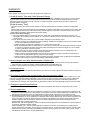
• SAFETY CAUTIONS •
(You must read these cautions before using the product)
In connection with the use of this product, in addition to carefully reading both this manual and the related
manuals indicated in this manual, it is also essential to pay due attention to safety and handle the product
correctly.
The safety cautions given here apply to this product in isolation. For information on the safety of the PLC
system as a whole, refer to the CPU module User's Manual.
Store this manual carefully in a place where it is accessible for reference whenever necessary, and
forward a copy of the manual to the end user.
A-1
A-1
REVISIONS
* The manual number is given on the bottom left of the back cover.
Print Date
* Manual Number
Apr., 2002 SH (NA)-080316E-A First edition
Revision
Japanese Manual Version SH-080265-A
This manual confers no industrial property rights or any rights of any other kind, nor does it confer any patent
licenses. Mitsubishi Electric Corporation cannot be held responsible for any problems involving industrial property
rights which may occur as a result of using the contents noted in this manual.
2002 MITSUBISHI ELECTRIC CORPORATION
A-2
A-2
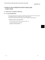
INTRODUCTION
Thank you for purchasing the Mitsubishi MELSEC-Q Series (Q mode) PLC.
Before using the product, please read this manual carefully to develop full familiarity with the functions and
performance of the Q Series (Q mode) PLC you have purchased, so as to ensure correct use.
CONTENTS
SAFETY CAUTIONS.....................................................................................................................................AREVISIONS ...................................................................................................................................................ACONTENTS...................................................................................................................................................AAbout Manuals...............................................................................................................................................A1. OVERVIEW
1 - 1 to 1 - 9
1.1 Features.................................................................................................................................................. 1 1.2 PID Control Overview............................................................................................................................. 1 1.3 Forward Oprration and Reverse Operation ........................................................................................... 1 1.4 PID Control ............................................................................................................................................. 1 1.4.1 Proportional operation (P operation) ............................................................................................... 1 1.4.2 Integral operation (I operation) ........................................................................................................ 1 1.4.3 Derivative operation (D operation) .................................................................................................. 1 1.4.4 PID operation................................................................................................................................... 1 2. STRUCTURE AND COMBINATIONS OF PROCESS CONTROL INSTRUCTIONS
1
2
2
2
3
3
4
4
4
5
5
3 - 1 to 3 - 9
3.1 Process Control Instructions and Data Configuration ........................................................................... 3 3.2 Local Work Memory ............................................................................................................................... 3 3.3 Data Used for Process Control Instructions .......................................................................................... 3 3.3.1 Loop memory................................................................................................................................... 3 3.3.2 Input data ......................................................................................................................................... 3 3.3.3 Block memory.................................................................................................................................. 3 3.3.4 Operation constant .......................................................................................................................... 3 3.3.5 Loop tag memory allocation contents ............................................................................................. 3 -
A-3
1
4
5
6
6
7
8
9
2 - 1 to 2 - 6
2.1 Instruction Configuration ........................................................................................................................ 2 2.2 Method for Specifying the Data in a Device........................................................................................... 2 2.2.1 For bit data....................................................................................................................................... 2 2.2.2 For word (16-bit) data ...................................................................................................................... 2 2.2.3 Double word (32-bit) data ................................................................................................................ 2 2.2.4 For real number data (floating-point data) ...................................................................................... 2 2.2.5 Process control instruction operation error ..................................................................................... 2 2.2.6 Instruction execution conditions ...................................................................................................... 2 2.2.7 Number of steps .............................................................................................................................. 2 2.2.8 Index qualification ............................................................................................................................ 2 2.3 Basic Loop Types Available by Combinations of Process Control Instructions.................................... 2 3. DATA USED FOR PROCESS CONTROL INSTRUCTIONS AND HOW TO SPECIFY DATA
1
2
3
7
A-3
1
3
4
4
5
6
6
7
4. HOW TO EXECUTE PROCESS CONTROL INSTRUCTIONS
4 - 1 to 4 - 2
4.1 Execution Time and Control Cycle......................................................................................................... 4 - 1
4.2 Concept of Program ............................................................................................................................... 4 - 2
5. EXECUTION CONDITION SWITCHING AND FUNCTIONS
5 - 1 to 5 - 3
5.1 Execution Condition Switching............................................................................................................... 5 5.1.1 Loop RUN/STOP ............................................................................................................................. 5 5.2 Functions ................................................................................................................................................ 5 5.2.1 Tracking function ............................................................................................................................. 5 5.2.2 Cascade loop tracking..................................................................................................................... 5 5.2.3 Loop selector tracking ..................................................................................................................... 5 6. INSTRUCTION LIST
1
1
2
2
2
3
6 - 1 to 6 - 6
6.1 How to Read the Instruction List Table .................................................................................................. 6 6.2 Functions ................................................................................................................................................ 6 6.2.1 I/O control instruction....................................................................................................................... 6 6.2.2 Control operation instruction............................................................................................................ 6 6.2.3 Compensation operation instruction................................................................................................ 6 6.2.4 Arithmetic operation instruction ....................................................................................................... 6 6.2.5 Comparison operation instruction ................................................................................................... 6 6.2.6 Auto tuning instruction ..................................................................................................................... 6 -
1
2
2
3
5
5
6
6
7. HOW TO READ INSTRUCTIONS
7 - 1 to 7 - 4
8. I/O CONTROL INSTRUCTIONS
8 - 1 to 8 - 36
8.1 Analog Input Processing (S.IN).............................................................................................................. 8 - 1
8.2 Output Processing with Mode Switching1 (S.OUT1)............................................................................. 8 - 6
8.3 Output Processing with Mode Switching2 (S.OUT2)............................................................................. 8 - 12
8.4 Manual Output (S.MOUT) ...................................................................................................................... 8 - 17
8.5 Time Rate Example (S.DUTY)............................................................................................................... 8 - 21
8.6 Batch Counter (S.BC)............................................................................................................................. 8 - 28
8.7 Pulse Retentive (S. PSUM).................................................................................................................... 8 - 32
9. CONTROL OPERATION INSTRUCTIONS
9 - 1 to 9 -111
9.1 Basics PID (S.PID) ................................................................................................................................. 9 - 1
9.2 2-degree-of-freedom PID (S.2PID) ........................................................................................................ 9 - 9
9.3 Position Type PID (S.PIDP) ................................................................................................................... 9 - 17
9.4 Sample PI (S.SPI) .................................................................................................................................. 9 - 26
9.5 I-PD Control (S.IPD)............................................................................................................................... 9 - 33
9.6 Blend PI Control (S.BPI)......................................................................................................................... 9 - 41
9.7 Rate (S.R)............................................................................................................................................... 9 - 48
9.8 Upper/lower Limit alarm (S.PHPL)......................................................................................................... 9 - 53
9.9 Lead/lag (S.LLAG).................................................................................................................................. 9 - 59
A-4
A-4
9.10 Integration (S.I)..................................................................................................................................... 9 - 61
9.11 Differentiation (S.D).............................................................................................................................. 9 - 63
9.12 Dead Time (S.DED) ............................................................................................................................. 9 - 65
9.13 High Selector (S.HS) ............................................................................................................................ 9 - 68
9.14 Low Selector (S.LS) ............................................................................................................................. 9 - 70
9.15 Intermediate Value Selection (S.MID).................................................................................................. 9 - 72
9.16 Average Value (S.AVE)........................................................................................................................ 9 - 75
9.17 Upper /lower Limiter (S.LIMT).............................................................................................................. 9 - 77
9.18 Change Rate Limiter 1 (S.VLMT1) ...................................................................................................... 9 - 79
9.19 Change Rate Limiter 2 (S.VLMT2) ...................................................................................................... 9 - 81
9.20 2-position ON/OFF (S.ONF2) .............................................................................................................. 9 - 83
9.21 3-position ON/OFF (S.ONF3) .............................................................................................................. 9 - 89
9.22 Dead Zone (S.DBND) .......................................................................................................................... 9 - 95
9.23 Program Setting Device (S.PGS)......................................................................................................... 9 - 97
9.24 Loop Selector (S. SEL)........................................................................................................................ 9 -102
9.25 Bump-less Transfer (S.BUMP) ........................................................................................................... 9 -108
9.26 Analog Memory (S.AMR) .................................................................................................................... 9 -110
10. COMPENSATION OPERATION INSTRUCTIONS
10 - 1 to 10 - 15
10.1 Polygon (S.FG)................................................................................................................................... 10 - 1
10.2 Inverted Polygon (S.IFG).................................................................................................................... 10 - 3
10.3 Standard Filter (S.FLT)....................................................................................................................... 10 - 5
10.4 Retentive (S.SUM) ............................................................................................................................. 10 - 8
10.5 Temperature/Pressure Compensation (S.TPC)................................................................................ 10 - 10
10.6 Engineering Value Conversion (S.ENG)............................................................................................ 10 - 12
10.7 Engineering Value Reverse Conversion (S.IENG)............................................................................ 10 - 14
11. ARITHMETIC OPERATION INSTRUCTIONS
11- 1 to 11 - 12
11.1 Addition (S.ADD) ................................................................................................................................ 11 - 1
11.2 Subtraction (S.SUB) ........................................................................................................................... 11 - 3
11.3 Multiplication (S.MUL) ........................................................................................................................ 11 - 5
11.4 Division (S.DIV) .................................................................................................................................. 11 - 7
11.5 Extraction (S.SQR)............................................................................................................................. 11 - 9
11.6 Absolute Value (S.ABS) ..................................................................................................................... 11 - 11
12. COMPARISON OPERATION INSTRUCTIONS
12.1 Comparison (S.
12.2 Comparison (S.
12.3 Comparison (S.
12.4 Comparison (S.
12.5 Comparison (S.
13. AUTO TUNING
12- 1 to 12 - 10
) ............................................................................................................................ 12 ) ............................................................................................................................ 12 )............................................................................................................................ 12 ) ........................................................................................................................ 12 ) ........................................................................................................................ 12 -
1
3
5
7
9
13- 1 to 13 - 12
13.1 Auto Tuning Instruction (S.AT1)......................................................................................................... 13 - 4
A-5
A-5
14. ERROR CODE
14- 1 to 14 - 2
14.1 Error Code List ................................................................................................................................... 14 - 1
APPENDICES
APP - 1 to APP - 21
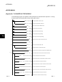
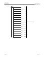
APPENDIX1 EXAMPLE PROGRAM.......................................................................................................APP - 1
APPENDIX 2 LOOP TAG MEMORY LIST ..............................................................................................APP - 5
2.1 PID Control (SPID), 2-degree-of-freedom PID Control (S2PID), Sample PI Control (SSPI)........APP - 5
2.2 I-PD Control (SIPD), Blend PI Control (SBPI)................................................................................APP - 7
2.3 Manual Output (SMOUT), Monitor (SMON)...................................................................................APP - 9
2.4 Manual Output with Monitor (SMWM), PIDP Control (SPIDP)......................................................APP -10
2.5 2 Position ON/OFF Control (SONF2), 3 Position ON/OFF Control (SONF3) ...............................APP -12
2.6 Batch Counter (SBC)......................................................................................................................APP -13
2.7 Rate Control (SR) ...........................................................................................................................APP -14
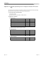
APPENDIX 3 OPERATION PROCESSING TIME ..................................................................................APP -16
3.1 The Operation Processing Time of Each Instruction.....................................................................APP -16
3.2 Operation Processing Time of 2-degree-of-freedom PID Control Loop........................................APP -19
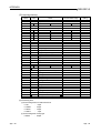
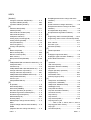
INDEX
A-6
Index- 1 to Index- 3
A-6
About Manuals
The manuals related to the Q/QnACPU are listed in the table below.
Please order those you require.
Related Manuals
Manual Name
Process CPU User's Manual (Hardware Design, Maintenance and Inspections)
Describes the specifications of the CPU module, power supply module, base unit, expansion cables, and
memory card.
(Sold separately)
Process CPU User's Manual (Function Explanation, Program Fundamentals)
This manual explains the functions, programming methods, devices and so on necessary to create programs
with the Process CPU.
(Sold separately)
QCPU (Q Mode)/QnACPU Programming Manual (Common Instructions)
This manual describes how to use the sequence instructions, basic instruction and application instructions.
(Sold separately)
QCPU (Q mode)/QnACPU Programming Manual (SFC)
Describes the system configuration, performance specifications, functions, programming, debugging, and error
codes, for MELSAP3.
(Sold separately)
QCPU (Q mode) Programming Manual (MELSAP-L)
Describes the system configuration, performance specifications, functions, programming, debugging, error
codes and others of MELSAP-L.
(Sold separately)
A-7
Manual Number
(Model Code)
SH-080314E
(13JR55)
SH-080315E
(13JR56)
SH-080039
(13JF58)
SH-080041
(13JF60)
SH-080076
(13JF61)
A-7
MEMO
A-8
A-8
1 OVERVIEW
MELSEC-Q
1 OVERVIEW
1
This manual describes the process control instructions equipped for the QnPHCPU.
1.1 Features
The process control instructions have the following features.
(1) Use of floating-point data
Capable of handling floating-point type real number data, the instructions can perform widerange and accurate operations.
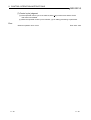
(2) Increased efficiency of system adjustment
Micro-blocked process control instructions are combined to perform PID control.
This enables actions to be confirmed on a process control instruction basis, ensuring efficient
system adjustment.
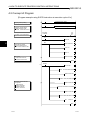
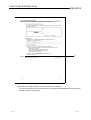
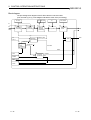
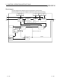
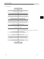
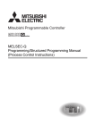
Example) Process control instructions used to carry out 2-degree-of-freedom PID control
Use name instruction common table.
Loop tag memory setting
Operation constant setting
K1
T0
Execution command
T0
PLS
M0
M0
CALL P1
RST
T0
FEND
P1
Process control instruction 1
(Input instruction)
Normal execution
FLT D0
R0
Microblock
S.IN
R0 R100 R200 R1000
S.IN instruction
EMOV R100 R20
Process control instruction 2
(Upper/lower limit alarm instruction)
Microblock
S.PHPL
R20 R120 R220 R1000
S.PHPL instruction
Set value (SV)
EMOV R120 R40
Process value (PV)
Process control instruction 3
(2-degree-of-freedom PID
control instruction)
Microblock
S.2PID R40 R140
R240 R1000
R300
S.2PID instruction
EMOV R140 R60
Process control instruction 4
(Output instruction)
Microblock
S.OUT1 R60 R160 R260 R1000
S.OUT1 instruction
INT R160 D1
RET
1-1
1-1
1 OVERVIEW
MELSEC-Q
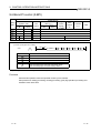
(3) Free combination of process control instructions for application to a wide
range of control
As an option, a process control instruction can be inserted in a loop that links process control
instructions.
1
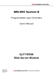
Add the extraction operation instruction (S.SQR) to perform the extraction operation of an input
signal to provide an output signal as shown below.
FIC
Regulator
FE flow meter
Liquid
Diaphragm valve
[Example of adding extraction operation instruction (S.SQR) to process control instructions]
Loop tag memory setting
Operation constant setting
Added as
option
Process control instruction
(Extraction operation
S.SQR
instruction)
Normal ON
S.SQR
R0
EM0V
R100
R100 R200
SD1506
instruction
Process control instruction
(2-degree-of-freedom PID
control instruction)
S.2PID instruction
R40
Normal ON
S.2PID R40 R140 R240 R1000 R300
(4) Automatic detection of various alarms
A system can be configured safely since various alarms are detected automatically in the
system.
1-2
1-2
1 OVERVIEW
MELSEC-Q
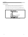
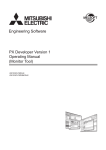
(5) PID algorithm using a velocity type incomplete differential format
Partial differential has the following advantages over the complete differential format.
(a) The differential gain is 1/ and the limit value can be set.
(b) The output contains time amplitude, so the system actually responds to the operation edge
so the derivative operation makes the movement valid.
Deviation
DV
PID
Manipulated
variable
Time(t)
1-3
1-3
1 OVERVIEW
MELSEC-Q
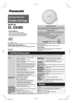
1.2 PID Control Overview
PID control is applied to the process control of flow rate, speed, air volume, temperature, tension,
compounding or like.
In a configuration shown in Fig. 1.1, PID control maintains the object to be controlled at a preset
value.
Process control instructions
are used
Subdivided (micro-blocked) processings
of PID control
Manual
MV
Set value
SV
PV
PID
operation
Automatic
MV
MV
D/A
converter
module
Controlled
system
A/D
converter
module
Sensor
Fig. 1.1 Example of application to process control
PID control compares the value measured in the detection section (process value: PV) with the
preset value (set value: SV) and adjust the output value (manipulated value: MV) to eliminate the
difference between the process value and set value.
In PID control, proportional operation (P), integral operation (I) and derivative operation (D) are
combined to calculate the manipulated value that will make the process value equal to the set
value fast and precisely.
• If the difference between the process value and set value is large, the manipulated value is
increased to make it close to the set value fast.
• When the difference between the process value and set value has reduced, the manipulated
value is decreased to make it equal to the set value slowly and precisely.
1-4
1-4
1 OVERVIEW
MELSEC-Q
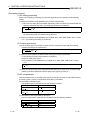
1.3 Forward Operation and Reverse Operation
(1) Forward operation is the action that increases the manipulated value when the process value
increases more than the set value.
(2) Reverse operation is the action that increases the manipulated value when the process value
is decreasing more than the set value.
(3) Forward operation and reverse action make the manipulated value larger as the difference
between the set value and the process value becomes larger.
(4) An example of process control performed by forward and reverse operations is shown in Fig.
1.2.
Temperature
Set value
Temperature
Process value
Set value
Time
Forward operation (for air conditioning)
Process value
Time
Reverse operation (for heating)
Fig. 1.2 Example of process control performed by forward and reverse operations
1-5
1-5
1 OVERVIEW
MELSEC-Q
1.4 PID Control
This section explains "proportional operation", "integral operation" and "derivative operation"
performed for PID control using the process control instructions.
1.4.1 Proportional operation (P operation)
This section explains the control method using proportional operation.
(1) Proportional operation is the action that compares the deviation (difference between the set
value and the process value) to find the manipulated value.
(2) The change in relationship between deviation (DV) and manipulated value (MV) using
proportional operation is shown using the following numeric expression.
MV
Kp • DV
Kp is called the proportional gain or proportional constant.
Deviation
(3) The proportional operation when the deviation is a constant stepped response is shown in Fig.
1.3.
DV
Manipulated
value
Time
K P DV
Time
Fig. 1.3 Proportional operation when deviation is constant
(4) The manipulated value fluctuates between 10 and 110%.
As Kp becomes larger the manipulated value corresponding to the deviation also becomes
larger making the compensation operation stronger.
(5) Offset occurs in proportional operation.
1-6
1-6
1 OVERVIEW
MELSEC-Q
1.4.2 Integral operation (I operation)
This section explains the control method using integral operation.
(1) Integral operation is the operation that continuously changes the manipulated value to
eliminate deviation when there is deviation.
This operation can eliminate the offset that occurs during control performed by a proportional
operation.
(2) The time from when a deviation occurs until the manipulated value of the integral operation
reaches the manipulated value of the proportional operation in the integral operation is called
integral time (TI).
(a) Increasing the integral time decreases the effect of integration.
(It will take time to stabilize.)
(b) Decreasing the integral time increases the effect of integration.
However, since the integral operation will be stronger, hunting may become greater.
Deviation
(3) The integral operation when the deviation is a constant value stepped response is shown in
Fig. 1.4.
DV
Time
Manipulated
value
Proportional operation integral operation manipulated value
Integral operation manipulated value
KP DV
Manipulated value in the proportional operation
TI
Time
Fig. 1.4 Integral operation when the deviation is a constant
(4) The integral operation is used as the PI operation that is combined with the proportional
operation or as the PID operation that is combined with the proportional operation and the
derivative operation.
Control cannot be carried out by merely performing the integral operation.
1-7
1-7
1 OVERVIEW
MELSEC-Q
1.4.3 Derivative operation (D operation)
This section explains the control method using the derivative operation.
(1) The derivative operation is an operation that adds the proportional manipulated value to the
change speed to eliminate deviation when a deviation has occurred.
The derivative operation can prevent large changes in the object control from disturbances.
(2) Derivative time (TD) indicates the length of time from when a deviation occurred until the
manipulated value of a derivative operation reaches that of a proportional operation.
Increasing the derivative time makes the derivative operation stronger.
Deviation
(3) The derivative operation when the deviation is a constant value stepped response is shown in
Fig. 1.5.
DV
Manipulated
value
Time
K P DV
Manipulated value for proportional operation
TD
Time
Fig. 1.5 Derivative operation when the deviation is a constant
(4) The derivative operation can be used as PD operation in combination with a proportional
operation or as a PID operation in combination with the proportional operation and integral
operation.
Control cannot be carried out by merely performing the derivative operation.
1-8
1-8
1 OVERVIEW
MELSEC-Q
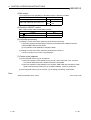
1.4.4 PID operation
This section explains the control operation using combinations of proportional operation (P
operation), integral operation (I operation), and derivative operation (D operation).
(1) The PID operation controls the calculated manipulated value using (P
I
D) operation.
Deviation
(2) The PID operation when the deviation is a constant value stepped response is shown in Fig.
1.6.
Manipulated value
Time
PID operation
PI
operation
I operation
P operation
D operation
Time
Fig. 1.6 PID operation when deviation is constant
1-9
1-9
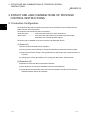
2 STRUCTURE AND COMBINATIONS OF PROCESS CONTROL
INSTRUCTIONS
MELSEC-Q
2 STRUCTURE AND COMBINATIONS OF PROCESS
CONTROL INSTRUCTIONS
2.1 Instruction Configuration
2
The instructions that can be used by the process control instructions can be divided into the
"instruction part" and "device part".
The instruction part and device part are as follows.
• Instruction part.................. This shows the functions for these instructions.
• Device part ....................... This shows the data required for operations and the storage
destination of the stored operation results.
The device part is classified as the source device and destination device.
(1) Source (S)
The source stores the data used for operation.
(a) In the process control instruction, specify the head device that stores the source data.
(b) Data must have been stored in the specified device until the process control instruction is
executed.
(c) Changing the source data allows you to change the data used in that instruction.
(2) Destination (D)
Destination is where the data is stored after operation.
(a) Sets the device for which the data will be stored in the destination.
(b) Depending on the instruction used, data used for operation must also be stored in the
destination before start of the operation.
2-1
2-1
2 STRUCTURE AND COMBINATIONS OF PROCESS CONTROL
INSTRUCTIONS
MELSEC-Q
2.2 Method for Specifying the Data in a Device
The following 4 types of data can be used by the process control instructions.
Data that can be handled
by process control instruction
Bit data
Numeric data
Integer data
Word data
2
Double word data
Real number data
(floating-point data)
2.2.1 For bit data
Bit data is handled on a single bit basis.
The QnPHCPU uses a word device for alarm condition or selection on a single bit basis.
By specifying the bit number of the word device, you can use the 1/0 of the specified bit number
as bit data.
b15
b0
Word device 1/0 1/0 1/0 1/0 1/0 1/0 1/0 1/0 1/0 1/0 1/0 1/0 1/0 1/0 1/0 1/0
1 in each bit can be used as ON,
or 0 as OFF.
Specify the bit of the word device in the form of " Word device . Bit No. ".
(Specify the bit number in hexadecimal.)
For example, specify the bit 5 (b5) of D0 as D0.5, and the bit 10 (b10) of D0 as D0.A.
However, you cannot specify the bits of the timer (T), retentive timer (ST), counter (C) and index
register (Z). (Example: You cannot specify Z0.0.)
2.2.2 For word (16-bit) data
Word data is the 16-bit numeric data that is used for the loop tag memory bit pack contents and
operation constants, etc.
• Decimal constant....................K-32768 to K32767
• Hexadecimal constant............H0000 to HFFFF
Example) For the loop tag memory ALM (standard value setting 4000H)
ALM
0
1
0
4
2-2
0
0
0
0
0
0
0
0
0
0
0
0
0
0
0
0
2-2
2 STRUCTURE AND COMBINATIONS OF PROCESS CONTROL
INSTRUCTIONS
MELSEC-Q
2.2.3 Double word (32-bit) data
Double word data is 32-bit numeric data.
• Decimal constant....................K-2147483648 to K2147483647
• Hexadecimal constant............H00000000 to HFFFFFFFF
When using double word data, specify the word device to be used in the lower-order 16 bits.
The 32-bit data is stored into the (specified word device number) and ((specified word device
number) 1).
Example) When D10 is specified for double word data, D10 and D11 are used.
D11
D10
(BW1) H
(BW1) L
2.2.4 For real number data (floating-point data)
The data required for operations and the operation results are 32-bit floating-point data.
Floating-point data is displayed as follows using 2 word devices.
1. [Fixed-point part]
2 [Exponent part]
The bit configuration when the floating-point data is expressed internally and its meaning are as
follows.
b31
b30
to
b23
b22
to
b16
b15
b23 to b30
Exponent part
to
b0
b0 to b22
Fixed-point part
b31
Fixed-point part sign
• Fixed-point part sign
0: Positive
1: Negative
This shows the fixed-point part sign in b31.
n
• Exponent part
This shows the 2 's n and b23 to b30.
The n from b23 to b30's BIN value is as follows.
b23 to b30
n
FFH
FEH FDH
Non-numeric
127
data
• Fixed-point part
126
81H
2
80H
1
7FH
0
7EH
-1
02H
01H
00H
Non-numeric
-125 -126
data
This shows the value of XXXXXX... in the 23 bits, b0 to b22, when 1.XXX
XXX... is represented in binary.
POINT
• The monitor function of GX Developer allows you to monitor the real number data of the
QnPHCPU.
-126
128
• The real number setting range is 0, 2
2 .
|value|
• To represent 0, set 0 in all of b0 to b31.
2-3
2-3
2 STRUCTURE AND COMBINATIONS OF PROCESS CONTROL
INSTRUCTIONS
MELSEC-Q
2.2.5 Process control instruction operation error
Operation errors from these process control instruction are stored in the following special
registers. For information regarding other than operation errors, refer to the error codes listed in
the QCPU(Q Mode)/QnACPU Programming Manual (Common Instructions). (The error codes are
stored in special register SD0.)
REMARK
The following contents for errors other than operation errors are stored in the special register.
Error code 4100.......... When there is data that cannot be handled.
4300.......... When the specified instruction is incorrect.
4301.......... When the process control instruction number of devices is incorrect.
4302.......... When a device that cannot be specified is specified.
(1) For error code 4100, the detailed information is stored in special registers SD1502 to
SD1503. At times other than when a process control instruction operation error occurs,
SD1502 and SD1503 are set to 0.
SD1502.......... This shows the error code when an error occurs in the process control
instruction.
SD1503.......... This shows the instruction process No. when an error occurs.
For an explanation of the error contents refer to the Chapter 14.
2.2.6 Instruction execution conditions
The process control instructions are instructions that are executed while the input condition is ON.
2.2.7 Number of steps
The number of process control instruction steps differs depending upon the number of instruction
characters, the device used, and whether or not an indirect setting is valid.
The basic number of steps for the extension instruction are as follows.
Number of steps in process control instruction
2
number of instruction characters (Note 1)
2
number of devices
Note 1: The number of characters is calculated by adding 1 when the number is odd. (For
example when rounding up the results of a division.)
S.IN
R0
R100 R200
1Step
The "S." of the instruction code is not
included in the number of characters.
1Step
R1000
7Step
1Step
1Step
1Step
2+2/2+4=7Step
For details refer to QCPU (Q Mode)/QnACPU Programming Manual (Common Instructions).
2-4
2-4
2 STRUCTURE AND COMBINATIONS OF PROCESS CONTROL
INSTRUCTIONS
MELSEC-Q
2.2.8 Index qualification
Index qualification usable with the process control instructions is the same as the one usable with
the basic instructions of the QnPHCPU.
2.3 Basic Loop Types Available by Combinations of Process Control
Instructions
Loop type
Structure
SET
Application
SV
PV
2-degree-of-freedom PID control
(S2PID)
INPUT
S.IN
S.PHPL
MV
S.2PID
SET
S.OUT1
SV
PV
INPUT
S.IN
S.PHPL
S.DUTY
S.IN
S.PHPL
MV
S.PID
SET
S.OUT1
S.IN
S.PHPL
PV
S.PHPL
MV
OUTPUT
SV
Sample PI control
(SSPI)
PV
INPUT
S.IN
S.PHPL
MV
S.SPI
SET
S.OUT1
PV
S.IN
S.PHPL
S.OUT1
PV
S.PHPL
SET
S.OUT1
OUTPUT
Control is performed to keep constant the
rate of the given manipulated value to the
other varying value.
OUTPUT
Depending on the sign (positive/negative)
of a deviation, operation to turn the
manipulated value ON or OFF is
performed.
SV
Rate control
(SR)
PV
INPUT1
OUTPUT
Used for a process where the manipulated
value may vary in a short period of time
and may be constant in a long period of
time.
MV
S.BPI
S.IN
S.PHPL
MV
S.R
SET
SV
2-position ON/OFF control
(SONF2)
S.OUT2
MV
PV
INPUT
S.IN
S.PHPL
S.ONF2
SET
SV
3-position ON/OFF control
(SONF3)
MV
PV
INPUT
S.IN
S.PHPL
S.ONF3
Used for a process that has long dead
time.
PI control is executed for only the period of
control execution time in each control
cycle and the output is kept constant after
that.
OUTPUT
SV
S.IN
Used for general PID control. (Position
type)
Conducts PID operation for each control
cycle.
Used to make slow response so that the
operation end and process are not given
impact when the set value is varied.
MV
S.IPD
SET
Blend PI control
(SBPI)
INPUT
OUTPUT
SV
I-PD control
(SIPD)
INPUT
OUTPUT
S.PIDP
SET
2-5
S.DUTY
SV
S.IN
Used for general PID control. (velocity
type)
Conducts PID operations for each control
cycle.
MV
S.PID
SET
PIDP control
(SPIDP)
INPUT
OUTPUT
SV
PV
INPUT
OUTPUT
SV
PV
PID control
(SPID)
Used for general PID control (2-degree-offreedom). (velocity type)
Conducts PID operations for each control
cycle.
MV
S.2PID
SET
INPUT
OUTPUT
OUTPUT
3-position ON/OFF control outputs signals
of three areas in response to the process
value to carry out control.
This control can suppress the sudden
variation of the manipulated value.
2-5
2 STRUCTURE AND COMBINATIONS OF PROCESS CONTROL
INSTRUCTIONS
MELSEC-Q
Loop type
Batch counter
(SBC)
Structure
INPUT
S.PSUM
S.BC
MV
Program setting device
(SPGS)
S.PGS
Manual output
(SMOUT)
S.MOUT
Monitor
(SMON)
INPUT
S.IN
S.PHPL
Manual output with monitor
(SMWM)
INPUT
S.IN
S.PHPL
Selector
(SSEL)
INPUT1
INPUT2
S.SEL
2-6
OUTPUT
OUTPUT
This is output in accordance with the
previously set value time change.
OUTPUT
This manually operates the operation
terminal end.
MV
PV
OUTPUT
PV
S.MOUT
Application
A valve or like is controlled ON/OFF in a
process of batch preparation for a tank or
like.
MV
OUTPUT
OUTPUT
This inputs the process value and detects
process errors such as upper/lower limit
alarms.
This inputs the process value and
conducts manual operation while checking
that no errors occur.
This is used to select signals.
2-6
3 DATA USED FOR PROCESS CONTROL INSTRUCTIONS AND HOW TO
SPECIFY DATA
MELSEC-Q
3 DATA USED FOR PROCESS CONTROL
INSTRUCTIONS AND HOW TO SPECIFY DATA
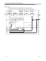
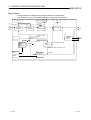
3.1 Process Control Instructions and Data Configuration
This section explains the data structure (data flow) used for process control instructions.
(a) Configuration when using loop tag
1) The loop units have common storage areas that show the control information. This
collection of common information is called a loop tag and the storage memory is called
the loop tag memory.
2) By monitoring the loop tag, you can monitor and tune the loop (control unit).
3
Block diagram
Loop tag memory
S.IN
Process
control
instruction
S.PHPL
Output
Process
control
instruction
Input
Operation
constant 1
3-1
Block
memory 1
S.2PID
Output
Process
control
instruction
Input
Operation
constant 2
Block
memory 2
S.OUT1
Output
Process
control
instruction
Output
Input
Operation
constant 3
Block
memory 3
Operation
constant 4
Block
memory 4
3-1
3 DATA USED FOR PROCESS CONTROL INSTRUCTIONS AND HOW TO
SPECIFY DATA
MELSEC-Q
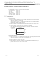
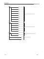
(b) Loop tag memory and operation constant locations in ladder diagram
Ladder diagram
Use name instruction common table.
Loop tag memory (96 words)
Loop tag memory setting
Instruction
used
Operation constant setting
Item
Standard
value setting
K1
T0
Execution command
T0
PLS
M0
M0
CALL P1
RST
T0
Data type
BIN16bit
+0
8H
BIN16bit
ALM
4000 H
BIN16bit
INH
4000 H
+1
MODE
+3
+4
BIN16bit
+10
S.PHPL
PV
0.0
Real number
+12
S.OUT1
MV
0.0
Real number
+14
S.2PID
SV
0.0
Real number
+16
S.2PID
DV
0.0
Real number
+18
S.OUT1
MH
100.0
Real number
+20
S.OUT1
ML
0.0
Real number
+22
S.PHPL
RH
100.0
Real number
3
FEND
P1 Normal execution
FLT D0
S.IN
R0
R0
R100 R200 R1000
EMOV R100 R20
S.PHPL
R20 R120 R220 R1000
EMOV R120 R40
S.2PID R40
R140 R240 R1000 R300
EMOV R140 R60
S.OUT1
+46
S.2PID
CT
1.0
Real number
+48
S.OUT1
DML
100.0
Real number
+50
S.2PID
DVL
100.0
Real number
+52
S.2PID
P
1.0
Real number
+54
S.2PID
I
10.0
Real number
+56
S.2PID
D
0.0
Real number
+58
S.2PID
GW
0.0
Real number
+60
S.2PID
GG
1.0
Real number
+62
S.OUT1
MVP
0.0
Real number
+64
S.2PID
0.0
Real number
+66
S.2PID
1.0
Real number
+90
0.0
Real number
+92
0.0
Real number
+94
0.0
Real number
R60 R160 R260 R1000
INT
R160 D1
RET
The symbols in the ladder diagram mean the following.
Start contact
3-2
Instruction
name
1) 2) 3) 4) 5)
Instruction name
1) Input data head device
2) Block memory head device
3) Operation constant head device
4) Loop tag memory head device
5) Set value head device
S.IN
R0
R100
R200
S.PHPL S.2PID
R20
R40
R120
R140
R220
R240
R1000
R300
S.OUT1
R60
R160
R260
3-2
3 DATA USED FOR PROCESS CONTROL INSTRUCTIONS AND HOW TO
SPECIFY DATA
MELSEC-Q
3.2 Local Work Memory
The local work memory is used as a temporary storage area in process control instruction
operation. (Memory used for micro blocks only)
The following instructions use the local work memory.
Instruction name
Remarks
S.LLAG (Lead/Lag)
S.D (Differentiation)
S.DED (Dead time)
S.FLT (Standard filter)
S.BUMP (Bump-less transfer)
S.AT1 (Auto tuning)
S.FG (Polygon)
S.IFG (Inverted polygon)
This stores the midway operation results for the OS itself.
(Cannot be used by the user.)
This stores the polygon coordinate value (Xn, Yn) used by
the user. Operations are conducted based on this.
Block diagram
Input data setting
Operation constant setting
Data for operation
Process control
instruction execution
Data after operation
Local work
memory
Operation result
Block memory
Ladder diagram
Operation constant setting
Normal ON
S.LLAG
R0
R100 R20
R200
Instruction name
S.LLAG (Lead/Lag)
Input data head device
R0
Block memory head device
R100
Operation constant head device
R20
Local work memory head device
R200
The application of the local work memory changes depending on the used instruction. Refer to the
explanation section of the corresponding instruction.
3-3
3-3
3 DATA USED FOR PROCESS CONTROL INSTRUCTIONS AND HOW TO
SPECIFY DATA
MELSEC-Q
3.3 Data Used for Process Control Instructions
The following data are used for the process control instructions.
• Loop tag memory
Section 3.3.1
• Input data
Section 3.3.2
• Block memory
Section 3.3.3
• Operation constant Section 3.3.4
• Local work memory Section 3.2
3.3.1 Loop memory
(1) Loop memory
(a) The loop memory is an area that stores the data used commonly by the process control
instructions specified as the loop type.
The loop memory also has an area that stores the data used by the QnPHCPU system
during process control instruction execution.
(b) The loop memory has the "loop tag memory" and "loop tag past value memory" areas.
(c) The loop memory consists of 128 words (word device: 128 points).
When setting the loop memory areas, specify the device that can occupy 128 words
consecutively.
Loop memory
Specified device
+0
Loop tag memory
96word
+95
+96 Loop tag past value memory
(Usage possible on the user's
side.)
+127
32word
(2) Loop tag memory
(a) The loop tag memory is an area that stores the data used commonly by the process control
instructions specified as the loop type indicated in Section 2.3.
(b) The loop tag memory consists of 96 words.
(c) Refer to Appendix 2 (Loop tag memory list) for the applications of the area used by the
process control instructions in the loop tag memory.
3-4
3-4
3 DATA USED FOR PROCESS CONTROL INSTRUCTIONS AND HOW TO
SPECIFY DATA
MELSEC-Q
(3) Loop tag past value memory
(a) The loop tag past value memory is an area used by the QnPHCPU system at the time of
process control instruction execution.
The user cannot write data to this memory during run.
If the user writes data to the loop tag past value memory during run, normal operation
cannot be performed.
(b) The loop tag past value memory is a 32-word area after the loop tag memory.
(c) At the start of the process control instruction, write "0" to the loop tag past value memory.
3.3.2 Input data
(1) Input data is variable data given to each process control instruction.
(2) The input data uses the block word of the block memory that stores the operation result of the
process control instruction executed previously.
Process control instruction
S.IN
Input data
Process control instruction
Operation result
Block word
S.PHPL
Input data
Operation result
Block word
Block bit
Block bit
Block memory*
Transferred by user
(3) The application of the input data changes depending on the used instruction. Refer to the
explanation section of the corresponding instruction.
REMARKS
*: Refer to Section 3.3.3 for the block memory.
3-5
3-5
3 DATA USED FOR PROCESS CONTROL INSTRUCTIONS AND HOW TO
SPECIFY DATA
MELSEC-Q
3.3.3 Block memory
The block memory is an area that stores the output information of the corresponding process
control instruction.
The block memory has "block words" and "block bits".
The application of the block memory changes depending on the used instruction.
Refer to the explanation section of the corresponding instruction.
Block memory
Specified device number
0
1
Block word
(2 words)
2
Block bit
2 words are used when real number
is stored into block word.
As block bit, each bit of one word
is used to store ON/OFF data.
(1) Block word (BW)
(a)The block word is an area that stores the operation result of the process control instruction.
(b) As the input data of the next process control instruction linked by the loop, the data stored
in the block word is used.
Process control instruction
Operation result
S.IN
Input data
Process control instruction
S.PHPL
Block word
Input data
Block bit
Operation result
Block word
Block bit
Transferred by user
(2) Block bit (BB)
The block bit is an area that stores the corresponding alarm data at process control
instruction execution.
As the block bits, 16 bits of b0 to b15 are represented as BB1 to BB16.
b12
b15
Block bit
B
B
1
6
B
B
1
5
B
B
1
4
B
B
1
3
b8
B
B
1
2
B
B
1
1
B
B
1
0
B
B
9
b0
b4
B
B
8
B
B
7
B
B
6
B
B
5
B
B
4
B
B
3
B
B
2
B
B
1
3.3.4 Operation constant
(1) The operation constant is an area that stores the data used by only one process control
instruction.
(2) The application of the operation constant changes depending on the used instruction. Refer to
the explanation section of the corresponding instruction.
3-6
3-6
3 DATA USED FOR PROCESS CONTROL INSTRUCTIONS AND HOW TO
SPECIFY DATA
MELSEC-Q
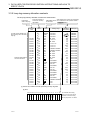
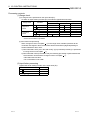
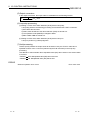
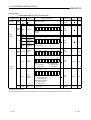
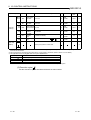
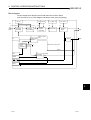
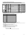
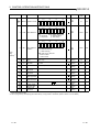
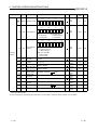
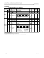
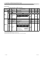
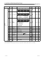
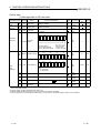
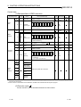
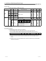
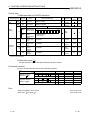
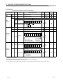
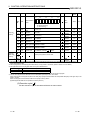
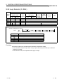
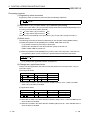
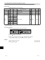
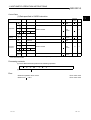
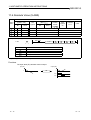
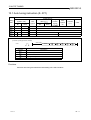
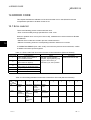
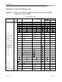
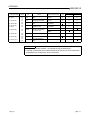
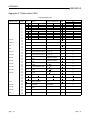
3.3.5 Loop tag memory allocation contents
The loop tag memory allocation contents are shown below.
Instructions
used in loop tag
After setting some values are changed by
Abbreviated name the numbers from the operation results.
of each item
(Highlighted areas)
Show the number of
words from the loop
tag header
Instruction
used
Item
Offset
Setting range
Standard
value setting
Data type
0
1
3
MODE
ALM
0 to FFFFH
0 to FFFFH
S.PHPL
4
10
0 to FFFFH
RL to RH
S.OUT1
S.2PID
12
14
INH
PV
MV
S.2PID
S.OUT1
16
18
20
For PID control (S2PID loop)
All commonly set in the same
loop tag
S.OUT1
S.PHPL
S.PHPL
S.PHPL
S.PHPL
S.PHPL
S.PHPL
S.IN
Sets the offset position
for each instruction
MH
ML
RH
RL
PH
28
30
32
PL
HH
LL
-10 to 110
-10 to 110
-999999 to 999999
-999999 to 999999
RL to RH
RL to RH
RL to RH
RL to RH
40
42
S.PHPL
S.2PID
44
46
48
S.OUT1
S.2PID
S.2PID
S.2PID
S.2PID
S.2PID
S.2PID
S.OUT1
S.2PID
S.2PID
HS
0 to 999999
0 to 999999
0 to 100
CTIM
DPL
CT
DML
DVL
P
I
56
58
60
D
GW
GG
62
64
MVP
100.0
0.0
100.0
0.0
100.0
1.0
100.0
100.0
1.0
0 to 999999
0 to 999999
0 to 999999
10.0
0.0
0.0
0 to 100
0 to 999999
-999999 to 999999
0 to 1
0 to 1
66
0.0
100.0
0.0
0.0
0 to 999999
0 to 100
0 to 100
50
52
54
0.0
0.0
100.0
0.0
0.2
0 to 1
38
S.PHPL
S.PHPL
0.0
0.0
-10 to 110
RL to RH
-110 to 110
SV
DV
22
24
26
8H
4000H
4000H
1.0
0.0
0.0
1.0
BIN16bit
BIN16bit
BIN16bit
Real number
Real number
Real number
Real number
Real number
Real number
Real number
Real number
Real number
Real number
Real number
Real number
Real number
Real number
Real number
Real number
Real number
Real number
Real number
Real number
Real number
Real number
Real number
Real number
Real number
Real number
Real number
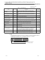
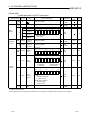
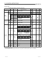
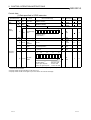
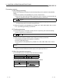
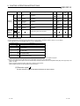
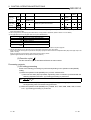
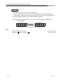
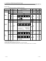
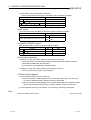
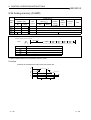
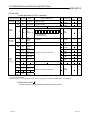
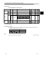
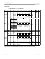
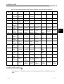
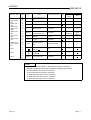
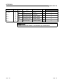
(1) Shows the contents of the bit pack using the loop tag data.
(a) ALM
b15 b14 b13 b12 b11 b10 b9 b8 b7 b6 b5 b4 b3 b2 b1 b0
S
P
A
3-7
D
M
L
A
O
O
P
A
S
E
A
H
H
A
L
L
A
P
H
A
P
L
A
D
P
P
A
D
P
N
A
D
V
L
A
M
H
A
M
L
A
The standard value setting
4000H is shown when manual
operation is conducted using
the loop step status. Use 0000H
3-7
3 DATA USED FOR PROCESS CONTROL INSTRUCTIONS AND HOW TO
SPECIFY DATA
MELSEC-Q
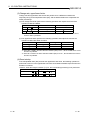
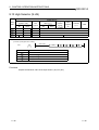
S: Stored by the system
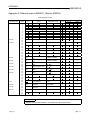
Table 3.1 ALM details list
Name
Abbreviation
Stop alarm
Description
Shows the loop stop status. Changes the loop mode to manual.
Conducts stop alarm processing for the output value (BW) and alarm
signal.
Conducts the change rate limiter for the input data and outputs the
change rate alarm. (For the output change upper limit value/control
value).
Shows that it has changed to open status when the operation output
signal has become disconnected, etc.
Sensor error alarm
Checks the upper limit value of the process equipment upper limit, and
outputs an alarm if the process value is higher than the upper limit
value.
Checks the lower limit value of the process equipment lower limit, and
outputs an alarm if the process value is lower than the lower limit value.
Checks the upper limit value of the process value, and outputs an alarm
if the process value is higher than the upper limit value.
Checks the lower limit value of the process value, and outputs an alarm
if the process value is lower than the lower limit value.
Outputs an alarm if the change rate is higher than the upward trend
change rate range.
Outputs an alarm if the change rate is lower than the downward trend
change rate range.
Conducts an error check and then outputs an alarm if over. In addition,
if the error check determines that the deviation is completely less than
the warning value and the error is reduced by a set value from the
warning value then the deviation large alarm will be released.
Conducts a check using the upper/lower limiter and if the limiter results
are larger than the input upper limit value an alarm is output.
A check is conducted by an upper/lower limiter and if the limiter results
are smaller than the input lower limit value an alarm is output.
SPA
Output change rate limit alarm
DMLA
Output open alarm
OOPA
Sensor alarm
SEA
Upper upper limit alarm
HHA
Lower lower limit alarm
LLA
Upper limit alarm
PHA
Lower limit alarm
PLA
Positive direction change rate
alarm
Negative direction change rate
alarm
DPPA
DPNA
Deviation large alarm
DVLA
Output upper limit alarm
MHA
Output lower limit alarm
MLA
U: Set by the user
Flag
establishment
conditions
U
S
S
S
S
S
S
S
S
S
S
S
S
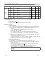
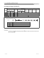
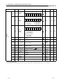
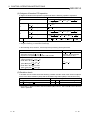
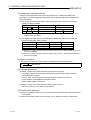
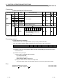
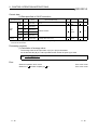
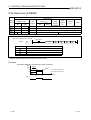
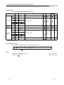
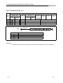
(b) INH
This prohibits alarm detection for each item. In addition, the alarms prohibited by INH are
not detected. (The INH bits 0 to 11 correspond to the bits 0 to 11 of ALM.)
b15 b14 b13 b12 b11 b10 b9 b8 b7
E
R
R
I
T
R
K
F
D
M
L
I
O
O
P
I
S
E
I
H
H
I
L
L
I
b6 b5 b4 b3 b2 b1 b0
P
H
I
P
L
I
D
P
P
I
D
P
N
I
D
V
L
I
M
H
I
M
L
I
Trucking flag
(We ask the user not touch this.)
All alarm detection prohibited
3-8
3-8
3 DATA USED FOR PROCESS CONTROL INSTRUCTIONS AND HOW TO
SPECIFY DATA
MELSEC-Q
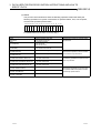
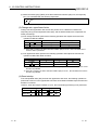
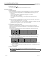
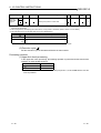
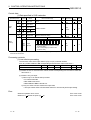
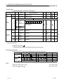
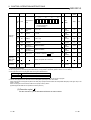
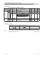
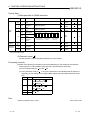
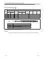
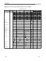
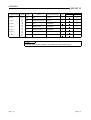
(c) MODE
The process control instructions have the following operation modes that satisfy the
following operations in a system connected to an operator station, PLC, host computer,
machine side operation panel and like.
b15 b14 b13 b12 b11 b10 b9 b8 b7 b6 b5 b4 b3 b2 b1 b0
C
S
V
C
M
V
C
C
B
C
A
B
C
M
B
C
A
S
A
U
T
M
A
N
L
C
C
L
C
A
L
C
M
For MODE make one of them a 1 bit only flag 1.
Operation mode
MAN
(MANUAL)
AUT
(AUTOMATIC)
CAS
(CASCADE)
CMV
(COMPUTER MV)
CSV
(COMPUTER SV)
CMB
(COMPUTER MANUAL BACK UP)
CAB
(COMPUTER AUTOMATIC BACK UP)
CCB
(COMPUTER CASCADE BACK UP)
LCM
(LOCAL MANIPULATED)
LCA
(LOCAL AUTOMATIC)
LCC
(LOCAL CASCADE)
3-9
Description
• Manual operation from OPS
• SV and MV can be set.
• Automatic operation
• SV can be set.
• MV cannot be set.
• Cascade operation
• SV and MV cannot be set.
• Automatic MV setting from host computer
• Automatic SV setting from host computer
• Manual operation backup when host
computer is abnormal
• Automatic operation backup when host
computer is abnormal
• Cascade operation backup when host
computer is abnormal
• Local manual operation
• Local automatic operation
Application
Monitoring and control from operator station
are performed.
Loop operation from host computer can be
performed and operation mode is controlled
and monitored at operator station.
During loop control by host computer, backup
is provided by predetermined operator station
when computer fails.
At startup of plant, operation and startup are
performed by loop display or like from other
than operator station and operation mode is
monitored by operator station.
• Local cascade operation
3-9
4 HOW TO EXECUTE PROCESS CONTROL INSTRUCTIONS
MELSEC-Q
4 HOW TO EXECUTE PROCESS CONTROL
INSTRUCTIONS
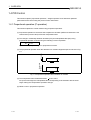
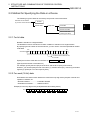
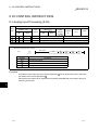
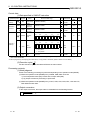
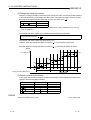
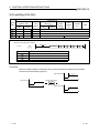
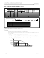
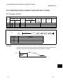
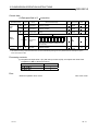
4.1 Execution Cycle and Control Cycle
(1) Execution cycle
(a) An execution cycle is an interval at which the process control instruction is executed.
(b) There are the following methods to execute the process control instruction in each
execution cycle.
1) Method using timer
A timer is used to measure the execution cycle and the process control instruction is
executed when the timer times out.
2) Method using interrupt programs
Any of interrupt programs of I28 to I31 is run in each execution cycle.
3) Method using fixed scan execution type program
A fixed scan execution type program is run in each execution cycle.
(c) Specify in the special registers (SD1500, SD1501) the value of the execution cycle used for
the process control instruction as a real number.
(2) Control cycle
(a) A control cycle is an interval in which PID control is performed for an instruction such as
S.2PID (2-degree-of-freedom PID).
As the control cycle, specify an integral multiple of the execution cycle.
The S.2PID or similar instruction counts the execution cycle in each execution cycle and
starts PID operation when the specified control cycle is reached.
(b) Specify in the loop tag memory (See Section 3.3.1) the control cycle used for the S.2PID or
similar instruction.
The S.2PID or similar instruction uses the value of the control cycle specified in the loop
tag memory to perform PID control.
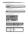
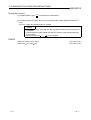
Example) When monitoring is performed at intervals of 1s in 2-degree-of-freedom PID
control and PID control is carried out at intervals of 5s.
0
1
3
2
5
4
6
7
8
9
10
11
12
13
14
15
16
17
18
(s)
Execution cycle
1s
1s
1s
1s
1s
5s
5s
5s
Control cycle
(Execution cycle)
N
S.2PID instruction performs processing at intervals of 5s.
POINT
When the control cycle is set to an integral multiple of the execution cycle,
monitoring such as a PV check can be performed in each execution cycle.
4-1
4-1
4
4 HOW TO EXECUTE PROCESS CONTROL INSTRUCTIONS
MELSEC-Q
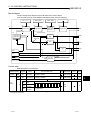
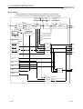
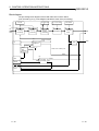
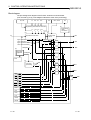
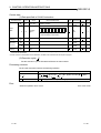
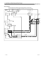
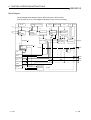
4.2 Concept of Program
[Program example using S.2PID instruction at execution cycle of 1s]
Loop tag memory setting
Loop tag memory setting
Operation constant setting
Operation constant setting
Setting of data for S.IN,
S.PHPL, S.2PID and S.OUT1
Execution
command
(1s)
K10
T0
Execution cycle measurement
T0
PLS M0
M0
4
MOV U0\GO D0
Input data (PV) setting
Import of data (PV) from
A/D converter module or like
CALL P1
RST T0
MOV D1 U2\G0
MV output
Output of MV from D/A
converter module or like
FEND
P1
SM400
FLT D0 R0
S.IN
R0 R100 R200 R1000
EMOV R100 R20
S.PHPL R20 R120 R220 R1000
Process control instruction
designation
S.IN instruction
S.PHPL instruction
S.2PID instruction
S.OUT1 instruction
EMOV R120 R40
S.2PID R40 R140 R240 R1000 R300
EMOV R140 R60
S.OUT1 R60 R160 R260 R1000
INT
R160 D1
RET
4-2
4-2
5 EXECUTION CONDITION SWITCHING AND FUNCTIONS
MELSEC-Q
5 EXECUTION CONDITION SWITCHING AND
FUNCTIONS
5.1 Execution Condition Switching
5.1.1 Loop RUN/STOP
If any loop component such as a detector or operation end other than the PLC fails, each loop can
be run/stopped to perform the maintenance of the corresponding loop.
The "SPA" bit of the alarm detection (ALM) is used to run/stop the corresponding loop.
(1) Basic operation during loop STOP
(a) Output status hold (The S.2PID instruction is output = 0)
(b) Alarm No detection (Process alarm)
(c) Make the control mode MAN.
5
5-1
5-1
5 EXECUTION CONDITION SWITCHING AND FUNCTIONS
MELSEC-Q
5.2 Functions
5.2.1 Tracking function
The tracking function includes the "bump-less function" and "output limiter processing".
(1) Bump-less function
The bump-less function prevents manipulated value (MV) output stepping changes when
switching from the automatic mode to manual mode and continuously controls MV output.
(2) Output limiter processing function
The output limiter processing function limits the upper limit and lower limit of the manipulated
value (MV) output by the PID operation during the automatic mode. This output limiter
processing function is only valid in the automatic mode and is not executed for manual data. In
addition, when the parameter tracking function execution validity is set to not valid when in the
automatic mode the output limiter processing function will not execute.
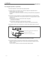
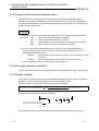
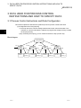
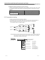
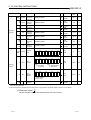
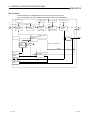
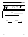
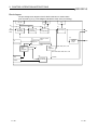
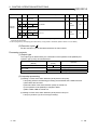
5.2.2 Cascade loop tracking
5
The process control loops that comprise a cascade loop use the manipulated value (MV) of a
primary loop (Loop 0) as the set value (SV) of a secondary loop (Loop 1).
Tracking is performed to prevent the sudden variation of the set value (SV) when the operation
mode of the secondary loop (Loop 1) is changed.
(1) The cascade PID loop Tracking processing is shown in the diagram below.
[Processing concept diagram]
SV
PID
PV1
Loop 0
Trucking data transmission
MV
SV
Trucking bit (TRK: 1)
PID
PV2
Loop 1
MV
(a) In cascade operation, the manipulated value (MV) of Loop 0 is transferred to the set value
(SV) of Loop 1.
(b) When cascade operation is not performed, the set value (SV) of Loop 1 is transferred to the
manipulated value (MV) of Loop 0.
(Tracking to the source specified as the input terminal of the set value (SV) of Loop 1)
5-2
5-2
5 EXECUTION CONDITION SWITCHING AND FUNCTIONS
MELSEC-Q
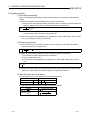
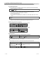
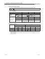
(2) Make the following settings to perform tracking.
(Tracking is performed when the operation mode is switched to other than CAS, CSV or CCB.)
For 2-degree-of-freedom PID (S.2PID), set the following operation constant items to specify
tracking.
Setting item
Setting
Tracking bit (TRK)
Set value pattern (SVPTN)
Set value pattern
Set value Used
1 (Tracking performed)
0 (Set value is upper loop MV.)
0 (E2 is used)
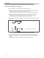
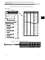
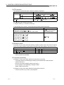
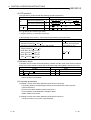
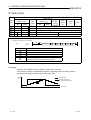
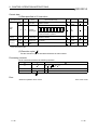
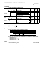
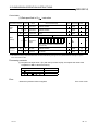
5.2.3 Loop selector tracking
Tracking is performed under the following conditions.
• The operation mode is any of MAN, CMB, CMV and LCM and the tracking bit (TRK) is 1
• When the operation mode is any of AUT, CAS, CAB, CCB, CSV, LCA and LCC
The tracking bit (TRK) is 1 and BB1 of BB is 1
Manipulated
value (MV)
Loop tag memory
Process value
(PV1)
S.IN
S.PHPL
S.2PID
Tracking
E1
S.OUT1
Loop 0
S.SEL
Loop 1
Process value
(PV2)
S.IN
S.PHPL
S.2PID
Loop tag memory
S.OUT1
E2
Manipulated
value (MV)
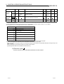
Example) When the S.SEL instruction uses the input value E1 and E1 uses the upper loop
(loop 0) MV, the S.SEL instruction's MV is trucked to loop 0's MV. The setting
that conducts Tracking is shown below.
Operation constant
Tracking bit
Set value pattern
5-3
S2
+4
+5
1
0
1
0
1
0: Tracking not performed.
0
1: Tracking performed.
Input value selection
0: E1 is selected.
1: E2 is selected.
Input value (E1) use
0: E1 is used.
1: E1 is not used.
Input value (E2) use
0: E2 is used.
1: E2 is not used.
Input value (E1) pattern
0: E1 is upper loop MV.
1: E1 is not upper loop MV.
Input value (E2) pattern
0: E2 is upper loop MV.
1: E2 is not upper loop MV.
5-3
6 INSTRUCTION LIST
MELSEC-Q
6 INSTRUCTION LIST
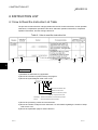
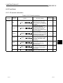
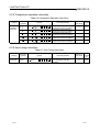
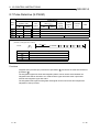
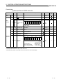
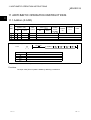
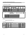
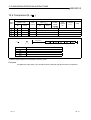
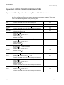
6.1 How to Read the Instruction List Table
The process control instruction is largely divided into the I/O control instructions, control operation
instructions, compensation operation instructions, arithmetic operation instructions, comparison
operation instructions, and auto tuning instructions.
Table 6.1 How to read the instruction list
1)
2)
4)
3)
5)
6)
6
Explanation
1) Classifies the instructions by application.
2) Shows the instruction symbols used by the program.
3) Shows the symbol diagram used in the circuit.
S.OUT2
S1 D1 S2 D2
Shows the destination side.
Shows the source side.
Shows the instruction symbol.
Figure 6.1 Symbols in the circut
Destination: Shows the destination of the data after operation.
Source:
Stores the data before the operation.
4) Shows the processing content of each instruction.
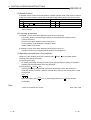
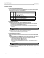
5) Shows the number of steps for each instruction. For information regarding the number of steps
refer to Item 2.2.7.
6) Shows the explanation page for each instruction.
6-1
6-1
6 INSTRUCTION LIST
MELSEC-Q
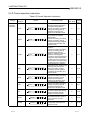
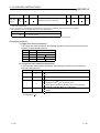
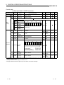
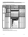
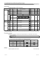
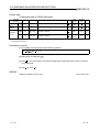
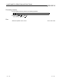
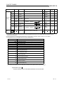
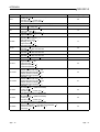
6.2 Functions
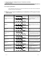
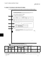
6.2.1 I/O control instruction
Table 6.2 I/O Control instruction
Category
Instruction
Symbols
Symbol
I/O control
instruction
6-2
S.IN
S.IN
S1 D1 S2 D2
S.OUT1
S.OUT1
S1 D1 S2 D2
S.OUT2
S.OUT2
S1 D1 S2 D2
S.MOUT
S.MOUT
S1 D1 S2 D2
S.DUTY
S.DUTY
S1 D1 S2 D2
S.BC
S.BC
S1 D1 S2 D2
S.PSUM
S.PSUM
S1 D1 S2 D2
Processing Details
Conducts the input data (PV)
Upper/lower limit check, input
limiter processing, engineering
value conversion, and digital filter
processing.
Calculates the MV (0 to 100%)
from the input data (MV),
processes the upper and lower
limit and Change rate limiter
processing, and conducts output
on time conversion.
Performs change rate,
upper/lower limiter processing
and output on time conversion
from the input data (MV).
Reads the MV of the loop tag
memory and performs output
conversion and alarm clear
processing.
Changes the ON/OFF rate within
a given cycle in proportion to the
input data (0 to 100%) and
outputs the result.
Compares the input data with the
set value and outputs bit data as
soon as the input data reaches
the set value.
Integrates the number of input
pulses and outputs the result.
See for
Number of
Descript
Basic Steps
ion
7
8- 1
8
8- 6
8
8-12
8
8-17
8
8-21
7
8-28
8
8-32
6-2
6
6 INSTRUCTION LIST
MELSEC-Q
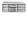
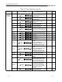
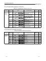
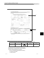
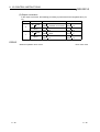
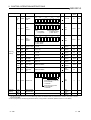
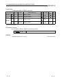
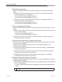
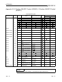
6.2.2 Control operation instruction
Table 6.3 Control Operation Instruction
Category
Instruction
Symbols
Symbol
Control
operation
instruction
6-3
S.PID
S.PID
S1 D1 S2 D2 S3
S.2PID
S.2PID
S1 D1 S2 D2 S3
S.PIDP
S.PIDP
S1 D1 S2 D2 S3
S.SPI
S.SPI
S1 D1 S2 D2 S3
S.IPD
S.IPD
S1 D1 S2 D2 S3
S.BPI
S.BPI
S1 D1 S2 D2 S3
S.R
S.R
S1 D1 S2 D2 S3
S.PHPL
S.PHPL
S1 D1 S2 D2
S.LLAG
S.LLAG
S1 D1 S2 D2
Processing Details
Conducts process value
derivative type PID operations.
(Incomplete differentiation)
Performs SV setting processing,
tracking processing, gain Kp
operation processing, PID
operation and deviation check.
Performs 2-degree-of-freedom
PID operation (incomplete
differentiation).
Performs SV setting processing,
tracking processing, gain Kp
operation processing, 2-degreeof-freedom PID operation and
deviation check.
Performs position type PID
operation.
Performs SV setting processing,
tracking processing, gain Kp
operation processing, PID
operation, deviation check and
operation mode judgment.
According to the result, performs
change rate, upper/lower limiter
and output on time conversion or
performs alarm clear processing
and output on time conversion.
Judges between the operating
time and hold time, and if it is the
operating time, performs SV
setting processing, tracking
processing, gain Kp operation
processing, SPI operation and
deviation check.
Performs I-PD operation.
Performs SV setting processing,
tracking processing, gain Kp
operation processing, IPD
operation and deviation check.
Performs blend PI operation.
Performs SV setting processing,
tracking processing, gain Kp
operation processing, BPI
operation and deviation check.
Performs engineering value
conversion, tracking processing,
change rate limiter and rate
operation on the input data.
Conducts an Upper limit
value/lower limit value check of
the PV output by the S.IN
instruction.
Conducts Lead/lag compensation
for input data and outputs the
operation results.
See for
Number of
Descript
Basic Steps
ion
9
9-1
9
9-9
9
9-17
9
9-26
9
9-33
9
9-41
8
9-48
8
9-53
8
9-59
6-3
6 INSTRUCTION LIST
MELSEC-Q
Table 6.3 Control Operation Instruction
Category
Control
operation
instruction
Instruction
Symbols
S.I
S.I
S1 D1 S2 D2
S.D
S.D
S1 D1 S2 D2
S.DED
S.DED
S1 D1 S2 D2
S.HS
S.HS
S1 D1 S2 D2
S.LS
S.LS
S1 D1 S2 D2
S.MID
S.MID
S1 D1 S2 D2
S.AVE
S.AVE
S1 D1 S2 D2
S.LIMT
S.LIMT
S1 D1 S2 D2
S.VLMT1
S.VLMT1
S1 D1 S2 D2
S.VLMT2
S.VLMT2
S1 D1 S2 D2
S.ONF2
S.ONF2
S1 D1 S2 D2 S3
S.ONF3
S.ONF3
S1 D1 S2 D2 S3
S.DBND
S.DBND
S1 D1 S2 D2
S.PGS
S.PGS
S1 D1 S2 D2
S.SEL
6-4
Symbol
S.SEL
S1 D1 S2 D2 S3
S.BUMP
S.BUMP
S1 D1 S2 D2
S.AMR
S.AMR
S1 D1 S2 D2
Processing Details
Conducts integral operations on
the input data and outputs the
operation results.
Conducts Derivative operations
on the input data and outputs the
operation results.
Delays the input data by the
specified dead time and then
outputs it.
Outputs the maximum value
among the input data.
Outputs the minimum value
among the input data.
Outputs the intermediate value
between the maximum value and
minimum value among the input
data.
Calculates and outputs the
average value of the input data.
Limits the output value with
hysteresis.
Limits the varying speed of the
output value.
Limits the varying speed of the
output value.
Performs two-position ON/OFF
control.
Performs SV setting processing,
tracking processing, MV
compensation, MV output and
two-position ON/OFF control.
Performs three-position ON/OFF
control.
Performs SV setting processing,
tracking processing, MV
compensation, MV output and
three-position ON/OFF control.
Provides a dead band and
performs output processing.
Provides a control output
according to the SV and MV
pattern.
Outputs the value selected by the
selection signal out of the input
data in the automatic mode, or
outputs the MV of the loop tag
memory in the manual mode.
Brings the output value closer to
the output set value from the
output control value gradually
when the mode select signal is
switched from manual to
automatic.
Increases or decreases the output
value at the fixed rate.
See for
Number of
Descript
Basic Steps
ion
7
9-61
7
9-63
8
9-65
7
9-68
7
9-70
8
9-72
8
9-75
8
9-77
9
9-79
9
9-81
9
9-83
9
9-89
8
9-95
8
9-97
9
9-102
8
9-108
8
9-110
6-4
6 INSTRUCTION LIST
MELSEC-Q
6.2.3 Compensation operation instruction
Table 6.4 Compensation Operation Instruction
Category
Compensation
operation
instruction
Instruction
Symbols
Symbol
S.FG
S.FG
S1 D1 S2 D2
S.IFG
S.IFG
S1 D1 S2 D2
S.FLT
S.FLT
S1 D1 S2 D2
S.SUM
S.SUM
S1 D1 S2 D2
S.TPC
S.TPC
S1 D1 S2 D2
S.ENG
S.ENG
S1 D1 S2 D2
S.IENG
S.IENG
S1 D1 S2 D2
Processing Details
Outputs the value that follows
the polygon pattern whose input
data is specified.
Outputs the value that follows
the inverted polygon pattern
whose input data is specified.
Outputs the average value of n
pieces of data sampled at the
specified data collection
intervals.
Integrates the input data and
outputs the result.
Makes temperature/pressure
compensation to the input data
and outputs the result.
Converts the input data into an
engineering value.
Reversely converts the input
data from the engineering value
and outputs the result.
See for
Number of
Descript
Basic Steps
ion
7
10- 1
8
10- 3
8
10- 5
8
10- 8
8
10-10
8
10-12
8
10-14
6.2.4 Arithmetic operation instruction
Table 6.5 Arithmetic Operation Instruction
Category
Arithmetic
operation
instruction
6-5
Instruction
Symbols
Symbol
S.ADD
S.ADD
S1 D1 S2 D2
S.SUB
S.SUB
S1 D1 S2 D2
S.MUL
S.MUL
S1 D1 S2 D2
S.DIV
S.DIV
S1 D1 S2 D2
S.SQR
S.SQR
S1 D1 S2 D2
S.ABS
S.ABS
S1 D1 S2 D2
Processing Details
Adds the input data with
coefficients.
Subtracts the input data with
coefficients.
Multiplies the input data with
coefficients.
Divides the input data with
coefficients.
Outputs the extraction ( ) of
the input data.
Outputs the absolute value of the
input data.
See for
Number of
Descript
Basic Steps
ion
8
11- 1
8
11- 3
8
11- 5
8
11- 7
8
11- 9
8
11-11
6-5
6 INSTRUCTION LIST
MELSEC-Q
6.2.5 Comparison operation instruction
Table 6.6 Comparison Operation Instruction
Category
Comparison
operation
instruction
Instruction
Symbols
Symbol
S.
S.
S1 D1 S2 D2
S.
S.
S1 D1 S2 D2
S.
S.
S1 D1 S2 D2
S.
S.
S1 D1 S2 D2
S.
S.
S1 D1 S2 D2
Processing Details
Compares the input data and
outputs the result of comparison.
Compares the input data and
outputs the result of comparison.
Compares the input data and
outputs the result of comparison.
Compares the input data and
outputs the result of comparison.
Compares the input data and
outputs the result of comparison.
See for
Number of
Descript
Basic Steps
ion
7
12- 1
7
12- 3
7
12- 5
7
12- 7
7
12- 9
6.2.6 Auto tuning instruction
Table 6.7 Auto Tuning Instruction
Category
Auto Tuning
Instruction
6-6
Instruction
Symbols
S.AT1
Symbol
S.AT1
S1 D1 S2 D2 D3
Processing Details
Performs auto tuning and makes
the initial setting of the PID
constants.
See for
Number of
Descript
Basic Steps
ion
9
13-4
6-6
7 HOW TO READ INSTRUCTIONS
MELSEC-Q
7 HOW TO READ INSTRUCTIONS
The following format will be used to explain to read instructions presented hereafter.
1)
2)
3)
4)
5)
7
1) Shows the item No. in the instruction summary.
2) is added to devices that can be used the instruction.
The usage classifications for devices that can be used is shown below.
Device
classifications
Usable
devices *3
Internal devices
(System, user)
Bit
X, Y, M,
L, SM, F,
B, SB,
FX, FY *2
MELSECNET/H
direct J
\
File register
Word
T, ST, C,
D, W, SD,
SW, FD,
@
Bit
R, ZR
J
J
J
J
\X
\Y
\B
\SB
Word
J
J
\W
\SW
Intelligent
function
module
U
\G
U
\G
Index
register
Z
Constant *1
Other *1
Z
Decimal constant
Hexadecimal constant
Real number constant
Character string constant
P, I, J, U,
DX, DY,
N, BL, TR,
BL\S, V
*1: The devices that can be set are given in the Constant and others field.
*2: FX and FY can be used with only bit data and FD with only word data.
*3: For the explanation of each device, refer to the user's manual (function explanation, program fundamentals) of the used
CPU module.
7-1
7-1
7 HOW TO READ INSTRUCTIONS
MELSEC-Q
6)
7)
7
3) This shows the expression and instruction execution conditions in the circuit mode.
Execution conditions
Normal execution
Displays the No. of the
explanation page
Nothing recorded
Executed during on
Executed once
during on
Executed once
during off
Nothing recorded
Nothing recorded
4) Explains the set data of the instruction.
5) Indicates the functions performed by the instruction.
6) Indicates the processing sequence of the instruction.
7) Lists the data specified for the instruction.
S and U in the Storage field indicate the following.
• S: Stored by the system
• U: Set by the user
7-2
7-2
7 HOW TO READ INSTRUCTIONS
MELSEC-Q
8)
upper
Upper
*1: When SEI or ERRI in the alarm detection inhibition (INH) is set to 1, SEA, BB1, BB2, and BB3
show 0 since the alarm is prohibited.
Upper
8) Explains each processing of the instruction.
7-3
7-3
7 HOW TO READ INSTRUCTIONS
MELSEC-Q
3
Range check ".
9)
9) Indicates the condition for error occurrence and the error number.
For errors other than the one described, refer to the QCPU (Q Mode)/QnACPU Programming
Manual (Common Instructions).
7-4
7-4
8 I/O CONTROL INSTRUCTIONS
MELSEC-Q
8 I/O CONTROL INSTRUCTIONS
8.1 Analog Input Processing (S.IN)
Internal devices
(System, user)
Setting
data
Bit
Word
File
register
Usable devices
MELSECNET/H
Intelligent
direct J \
function
module
Bit
Word
U \G
Index
register
Zn
Constant
K, H
Other
S1
D1
S2
D2
[Instruction symbol] [Execution condition]
Start contact
S.IN
S.IN
Set data
S1
D1
S2
D2
S1
D1
S2
D2
Description
Input data head device
Block memory head device
Operation constant head device
Loop tag memory head device
Functions
Converts the input value (E1) of the device specified in S1 into an engineering value, and stores
the result into the device specified in D1 .
Also performs the range check, input limiter processing and digital filter processing of the input
value (E1) at this time.
8
8-1
8-1
8 I/O CONTROL INSTRUCTIONS
MELSEC-Q
Block diagram
The processing block diagram of the S.IN instruction is shown below.
(The numerals (1) to (5) in the diagram indicate the order of the processing.)
HH, H, L, LL
(1)
NMAX, NMIN
EMAX, EMIN
(2)
(3)
E1
Range check
RUN(SPA
(5)
(4)
Engineering
value reverse
conversion
Input limiter
Digital filter
BW
0)
Upper limit alarm
Loop stop
judgment
STOP(SPA 1)
Lower
limit alarm
AND
BB2
AND
BB3
BB1
OR
SPA
SEA
(5)
ERRI
Last BW
SEI
MAN
MODE
Loop stop
processing
All OFF
Control data
Data specified in S.IN instruction
Specified position
Input data
S1 +0
+1
D1 +0
+1
Symbol
Recommended range *1
Name
E1
Input value
-999999 to 999999
BW
Output value
(-999999 to 999999)
Alarm
b15
Unit
%
Data format
Standard
value
Store
Real number
U
Real number
S
BIN
16bit
S
BB
Block
memory
BB1
+2
BB2
BB3
Input upper
limit alarm
Input lower
limit alarm
b12
b8
b4
b0
B B
B B
3 2
B
B
1
(0: Without alarm)
(1: With alarm)
*1: The data of the item(s) where the values within the recommended range are given in the parentheses are stored by the system.
Users cannot set the data.
8-2
8-2
8
8 I/O CONTROL INSTRUCTIONS
Specified position
S2
Symbol
+0
+1
EMAX
+2
+3
EMIN
+4
+5
+6
+7
Operation
constant
NMAX
NMIN
+8
+9
HH
+10
+11
H
+12
+13
L
+14
+15
LL
MELSEC-Q
Recommended range *1
Name
Engineering
conversion
upper limit
Engineering
conversion
lower limit
Input upper
limit
Input lower
limit
Upper limit
range error
occurrence
Upper limit
range error
return
Lower limit
range error
return
Lower limit
range error
occurrence
Unit
Data format
Standard
value
Store
-999999 to 999999
%
Real
number
100.0
U
-999999 to 999999
%
Real
number
0.0
U
100.0
U
0.0
U
Real
number
Real
number
-999999 to 999999
-999999 to 999999
-999999 to 999999
Real
number
110.0
U
-999999 to 999999
Real
number
100.0
U
-999999 to 999999
Real
number
0.0
U
-999999 to 999999
Real
number
-10.0
U
BIN
16bit
8H
S/U
BIN
16bit
4000H
S/U
BIN
16bit
4000H
S/U
0 to FFFFH
D1
+1
MODE
Operation
mode
b15
b12
b8
b4
b0
C C C C C C A M L L L
S M C A M A U A C C C
V V B B B S T N C A M
0 to FFFFH
b15
+3
ALM
b12
S
P
A
Alarm
detection
b8
SPA
0: Loop RUN
1: Loop STOP
Loop tag
memory *2
b4
b0
S
E
A
SEA
(0: Without alarm)
(1: With alarm)
0 to FFFFH
b15
+4
INH
Alarm
detection
inhibition
b12
E
R
R
I
b8
b4
b0
S
E
I
0: Alarm enable
1: Alarm inhibit
+38
Filter
Real
0 to 1
0.2
+39
coefficient
number
*1: The data of the item(s) where the values within the recommended range are given in the parentheses are stored by the system.
Users cannot set the data.
*2: The loop tag memory and loop tag past value memory occupy a total of 128 words. (Refer to Section 3.3.1 for details.)
(2) Execution cycle ( T)
Set the execution cycle in SD1500 and SD1501 as real numbers.
8-3
8-3
U
8 I/O CONTROL INSTRUCTIONS
MELSEC-Q
Processing contents
(1) Range check
(a) A range check is performed on the input value (E1).
An alarm is output if the input value (E1) exceeds the upper/lower limit value.
Range check
Condition
BB2
Range check result (alarm output)
BB3
BB1, SEA
*1
*1
E1 HH
1
1
E1 H
0
0
H E1 HH
Last value
Last value
*1
*1
E1 LL
1
1
Lower limit
E1 L
0
0
check
LL E1 L
Last value
Last value
*1: When SEI or ERRI in the alarm detection inhibition (INH) is set to 1, SEA, BB1, BB2 and BB3
show 0 since the alarm is prohibited.
Upper limit
check
(b) Last value hold processing
When a range excess occurs (BB1 1) in the range check, whether operation will be
continued unchanged or the S.IN instruction will be terminated is judged depending on
whether SM1500 is ON or OFF.
1) When SM1500 is OFF (not in the hold mode), "(2) Input limiter processing" is performed
if a range excess occurs (BB1 1).
2) When SM1500 is ON (in the hold mode), the following processing is performed and the
S.IN instruction is terminated if a range excess occurs (BB1 1).
• BW retains the last value.
• Error information is set in BB.
(2) Input limiter processing
Upper/lower limiter setting is made on the input value (E1).
Condition
E1 NMAX
E1 NMIN
NMIN E1 NMAX
8-4
Result (T1)
NMAX
NMIN
E1
8-4
8 I/O CONTROL INSTRUCTIONS
MELSEC-Q
(3) Engineering value reverse conversion
The result (T1) of the input limiter is converted reversely from the engineering value according
to the following expression.
T2
EMAX
T2
(EMAX EMIN)
T1 NMIN
NMAX NMIN
EMIN
EMIN
NMIN
NMAX
T1
(4) Digital filter
The input value (E1) is digitally filtered according to the following expression.
The digital filter is used to reduce noise.
BW
T2
(Previous BW value
T2)
(5) Loop stop processing
(a) Setting 1 in SPA of the alarm detection (ALM) selects a loop stop.
A loop stop performs the following processing and terminates the S.IN instruction.
1) BW retains the last value.
2) SEA of the alarm detection (ALM) are turned to 0.
3) The operation mode (MODE) is changed to MAN.
4) BB1 to BB3 of BB are turned to 0.
(b) Setting 0 in SPA of the alarm detection (ALM) selects a loop run.
A loop run performs "(1) Range check".
ERROR
• When an operation error occurs
8-5
Error code: 4100
8-5
8 I/O CONTROL INSTRUCTIONS
MELSEC-Q
8.2 Output Processing with Mode Switching1 (S.OUT1)
Internal devices
(System, user)
Setting
data
Bit
Word
File
register
Usable devices
MELSECNET/H
Intelligent
direct J \
function
module
Bit
Word
U \G
Index
register
Zn
Constant
K, H
Other
S1
D1
S2
D2
[Instruction symbol] [Execution condition]
Start contact
S.OUT1
S.OUT1
Set data
S1
D1
S2
D2
S1
D1
S2
D2
Description
Input data head device
Block memory head device
Operation constant head device
Loop tag memory head device
Functions
Calculates the manipulated value (MV) by performing input addition processing from the input
value (E1
MV) of the device specified in S1 , and stores the result into the device specified in
D1 .
Also performs the change rate, upper/lower limiter, reset windup and output conversion
processings of the calculated manipulated value (MV) at this time.
8-6
8-6
8 I/O CONTROL INSTRUCTIONS
MELSEC-Q
Block diagram
The processing block diagram of the S.OUT1 instruction is shown below.
(The numerals (1) to (6) in the diagram indicate the order of the processing.)
MH, ML, DML
(1)
E1
Mode
judgment
RUN(SPA
(6)
Loop
stop
judgment
AUT (2)
or like
Input addition
processing
0)
STOP(SPA 1)
MV
(3)
MVP
(4)
Change rate,
upper/lower
limiter
NMAX, NMIN
(5)
Reset windup
Output
conversion
processing
BW
MAN or like
Alarm clear
processing
Upper limit alarm
Lower limit alarm
Change rate alarm
SPA
ERRI
MHI
AND
BB2
ERRI
MLI
AND
BB3
ERRI
DMLI
AND
BB4
MHA
MLA
DMLA
TRKF
BB1
OR
MODE
(6)
All OFF
MAN
8-7
Last BW
Loop stop
processing
All OFF
8-7
8 I/O CONTROL INSTRUCTIONS
MELSEC-Q
Control data
(1) Data specified in S.OUT1 instruction
Specified position
Input data
S1 +0
+1
D1 +0
+1
Symbol
E1
Input value
( MV)
-999999 to 999999
BW
Output value
(-999999 to 999999)
BB
BB1
Block
memory
BB2
+2
BB3
BB4
S2 +0
Operation
constant
+1
Recommended range *1
Name
NMAX
+2
+3
NMIN
D2 +1
MODE
%
Alarm
b15
b12
b8
Output upper
limit alarm
Output lower
limit alarm
(0: Without alarm)
Output change (1: With alarm)
rate alarm
Output
conversion
-999999 to 999999
upper limit
Output
conversion
-999999 to 999999
lower limit
0 to FFFFH
Operation
mode
b15
b12
Unit
b4
b4
Standard
value
Store
Real
number
U
Real
number
S
BIN
16bit
S
b0
B
B
4
b8
Data format
B B
B B
3 2
B
B
1
b0
C C C C C C A M L L L
S M C A M A U A C C C
V V B B B S T N C A M
Real
number
100.0
U
Real
number
0.0
U
BIN
16bit
8H
S/U
BIN
16bit
4000H
S/U
BIN
16bit
4000H
S/U
0 to FFFFH
b15
+3
ALM
b12
S
P
A
Alarm
detection
b8
b0
M M
H L
A A
SPA
0: Loop RUN
1: Loop STOP
Loop tag
memory *2
b4
D
M
L
A
DMLA, MHA, MLA
(0: Without alarm)
(1: With alarm)
0 to FFFFH
b15
E
R
R
I
+4
INH
Alarm
detection
inhibition
b12
T
R
K
F
b8
D
M
L
I
TRKF
(0: Without tracking)
(1: With tracking)
b4
b0
M M
H L
I I
ERRI, DMLI, MHI, MLI
0: Alarm enable
1: Alarm inhibit
+12
Manipulated
Real
MV
(-10 to 110)
%
0.0
+13
value
number
*1: The data of the item(s) where the values within the recommended range are given in the parentheses are stored by the system.
Users cannot set the data.
*2: The loop tag memory and loop tag past value memory occupy a total of 128 words. (Refer to Section 3.3.1 for details.)
8-8
8-8
S
8 I/O CONTROL INSTRUCTIONS
Specified position
D2
Loop tag
memory *2
Symbol
MELSEC-Q
Recommended range *1
Name
Unit
Data format
Standard
value
Store
+18
+19
MH
Output upper
limit value
-10 to 110
%
Real
number
100.0
U
+20
+21
ML
Output lower
limit value
-10 to 110
%
Real
number
0.0
U
+48
+49
DML
Output
change rate
limit value
0 to 100
%
Real
number
100.0
U
+54
+55
I
Integral
constant
0 to 999999
s
Real
number
10.0
U
MV inside
Real
operation
(-999999 to 999999)
%
0.0
number
value
*1: The data of the item(s) where the values within the recommended range are given in the parentheses are stored by the system.
Users cannot set the data.
*2: The loop tag memory and loop tag past value memory occupy a total of 128 words. (Refer to Section 3.3.1 for details.)
+62
+63
MVP
S
(2) Execution cycle ( T)
Set the execution cycle in SD1500 and SD1501 as real numbers.
Processing contents
(1) Mode judgment
Either of the following processings is performed depending on the operation mode (MODE).
(a) When the operation mode (MODE) is any of MAN, CMB, CMV and LCM (alarm clear
processing)
1) MHA, MLA and DMLA of the alarm detection (ALM) are turned to 0.
2) BB1 to BB4 of BB are turned to 0.
3) The tracking flag (TRKF) of the alarm detection inhibition (INH) is turned to 1.
4) "(5) Output conversion processing" is performed and the instruction is terminated.
(b) When the operation mode (MODE) is any of AUT, CAB, CAS, CCB, CSV, LCA and LCC,
"(2) Input addition processing" is performed.
However, when SEA of the alarm detection (ALM) is 1 and SM1501 is ON (with hold), BB1
to BB4 are turned to 0 and the S.OUT1 instruction is terminated.
(2) Input addition processing
The temporary MV (T) is calculated on the basis of the input value (E1
MV).
(a) When the tracking flag (TRKF) of the alarm detection inhibition (INH) is 1, the following
processing is performed.
1) The manipulated value (MV) is stored into the MV internal operation value (MVP).
2) The input value (E1) is changed to 0. ( MV 0)
3) The tracking flag (TRKF) of the alarm detection inhibition (INH) is turned to 0.
4) The temporary MV (T) is calculated with the following expression.
T
MVP
8-9
E1
MVP
T
8-9
8 I/O CONTROL INSTRUCTIONS
MELSEC-Q
(b) When the tracking flag (TRKF) of the alarm detection inhibition (INH) is 0, the temporary
MV (T) is calculated with the following expression.
T
E1
MVP
MVP
T
(3) Change rate, upper/lower limiter
Change rate and upper/lower limit checks are performed on a difference between the
temporary MV (T) and manipulated value (MV), and the data and alarm are output after the
limiter processings.
(a) The change rate limiter performs the following operation and outputs the result of the
operation to BB4 and DMLA.
Condition
|T
MV| DML
MV) DML
(T
MV)
DML
(T
BB4, DMLA
Result (T1)
0
*1
1
*1
1
T
MV
MV
DML
DML
*1: When DMLI or ERRI in the alarm detection inhibition (INH) is set to 1, DMLA and BB4 show 0
since the alarm is prohibited.
(b) The upper/lower limiter performs the following operation and outputs the result of the
operation to BB2, BB3, MHA and MLA.
Condition
T1 MH
T1 ML
ML T1 MH
BB3, MLA
0
*3
1
0
BB2, MHA
*2
1
0
0
MV
MH
ML
T1
*2: When MHI or ERRI in the alarm detection inhibition (INH) is set to 1, MHA and BB2 show 0 since
the alarm is prohibited.
*3: When MLI or ERRI in the alarm detection inhibition (INH) is set to 1, MLA and BB3 show 0 since
the alarm is prohibited.
(4) Reset windup
If the manipulated value (MV) exceeds the upper/lower limit value, the following operation is
performed to return it to the upper/lower limit value and enable immediate response when the
deviation is inverted.
However, when the integral constant (T1) is 0, the reset windup processing is not performed.
Condition
8 - 10
When MHA
1,
When MLA
1,
Operation expression
T
TI
T
TI
1
MVP
1
MVP
T
(MH
TI
T
(ML
TI
T)
T
T)
T
8 - 10
8 I/O CONTROL INSTRUCTIONS
MELSEC-Q
(5) Output conversion
In the output conversion, the output value is calculated from the following formula.
BW
NMAX NMIN
100
MV
NMIN
(6) Loop stop processing
(a) Setting 1 in SPA of the alarm detection (ALM) selects a loop stop.
A loop stop performs the following processing and terminates the S.OUT1 instruction.
1) BW retains the last value.
2) DMLA, MHA and MLA of the alarm detection (ALM) are turned to 0.
3) The operation mode (MODE) is changed to MAN.
4) BB1 to BB4 of BB are turned to 0.
(b) Setting 0 in SPA of the alarm detection (ALM) selects a loop run.
A loop run performs "(1) Mode judgment".
(7) Hold processing
Used to specify whether the output value will be held or not by the S.OUT1 instruction is
specified at sensor error occurrence (detected by the S.IN instruction) in the loop stop
processing.
Use SM1501 to select whether the manipulated value (MV) will be held or not at sensor alarm
occurrence.
• SM1501 OFF: Manipulated value (MV) will not be held.
• SM1501 ON: Manipulated value (MV) will be held.
ERROR
• When an operation error occurs
8 - 11
Error code: 4100
8 - 11
8 I/O CONTROL INSTRUCTIONS
MELSEC-Q
8.3 Output Processing with Mode Switching2 (S.OUT2)
Internal devices
(System, user)
Setting
data
Bit
Word
File
register
Usable devices
MELSECNET/H
Intelligent
direct J \
function
module
Bit
Word
U \G
Index
register
Zn
Constant
K, H
Other
S1
D1
S2
D2
[Instruction symbol] [Execution condition]
Start contact
S.OUT2
S.OUT2
Set data
S1
D1
S2
D2
S1
D1
S2
D2
Description
Input data head device
Block memory head device
Operation constant head device
Loop tag memory head device
Functions
Converts the input value (E1 MV) of the device specified in S1 into an output, and stores the
result into the device specified in D1 .
Also performs the change rate, upper/lower limiter processing and output conversion processing
of the input value at this time.
8 - 12
8 - 12
8 I/O CONTROL INSTRUCTIONS
MELSEC-Q
Block diagram
The processing block diagram of the S.OUT2 instruction is shown below.
(The numerals (1) to (4) in the diagram indicate the order of the processing.)
MH, ML, DML
NMAX, NMIN
MV
E1
(1)
(2)
Mode
judgment
RUN(SPA 0)
(4)
Loop
stop
judgment
AUT or like
MAN or like
STOP(SPA 1)
(3)
Change rate,
upper/lower
limiter
Output
conversion
processing
BW
Alarm clear
processing
Upper limit alarm
Lower limit alarm
Change rate alarm
SPA
ERRI
MHI
AND
BB2
ERRI
MLI
AND
BB3
ERRI
DMLI
AND
BB4
MHA
MLA
DMLA
OR
BB1
MODE
(4)
All OFF
MAN
8 - 13
Last BW
Loop stop
processing
All OFF
8 - 13
8 I/O CONTROL INSTRUCTIONS
MELSEC-Q
Control data
(1) Data specified in S.OUT2 instruction
Specified position
Input data
S1 +0
+1
D1 +0
+1
Symbol
E1
Input
value(MV)
-999999 to 999999
BW
Output value
(-999999 to 999999)
BB
BB1
Block
memory
BB2
+2
BB3
BB4
S2
Operation
constant
Recommended range *1
Name
+0
+1
NMAX
+2
+3
NMIN
Alarm
Output upper
limit alarm
Output lower
limit alarm
Output change
rate alarm
Output
conversion
upper limit
Output
conversion
lower limit
b15
b12
Unit
%
b8
b4
Data format
Standard
value
Store
Real
number
U
Real
number
S
BIN
16bit
S
b0
B
B
4
B B
B B
3 2
B
B
1
(0: Without alarm)
(1: With alarm)
-999999 to 999999
Real
number
100.0
U
-999999 to 999999
Real
number
0.0
U
BIN
16bit
8H
S/U
BIN
16bit
4000H
S/U
BIN
16bit
4000H
S/U
0 to FFFFH
D2 +1
MODE
Operation
mode
b15
b12
b8
b4
b0
C C C C C C A M L L L
S M C A M A U A C C C
V V B B B S T N C A M
0 to FFFFH
b15
+3
ALM
b12
S
P
A
Alarm
detection
b8
b4
D
M
L
A
b0
M M
H L
A A
SPA
0: Loop RUN
1: Loop STOP
DMLA, MHA, MLA
(0: Without alarm)
(1: With alarm)
0 to FFFFH
Loop tag
memory *2
b15
+4
INH
Alarm
detection
inhibition
E
R
R
I
b12
b8
D
M
L
I
b4
b0
M M
H L
I I
0: Alarm enable
1: Alarm inhibit
+12
+13
+18
+19
+20
+21
Manipulated
Real
(-10 to 110)
%
0.0
value
number
Output upper
Real
-10 to 110
%
100.0
MH
limit value
number
Output lower
Real
-10 to 110
%
0.0
ML
limit value
number
Output change
+48
Real
DML rate
0 to 100
%
100.0
+49
number
limit value
*1: The data of the item(s) where the values within the recommended range are given in the parentheses are stored by the system.
Users cannot set the data.
*2: The loop tag memory and loop tag past value memory occupy a total of 128 words. (Refer to Section 3.3.1 for details.)
8 - 14
MV
S
U
U
U
8 - 14
8 I/O CONTROL INSTRUCTIONS
MELSEC-Q
(2) Execution cycle ( T)
Set the execution cycle in SD1500 and SD1501 as real numbers.
Processing contents
(1) Mode judgment
Either of the following processings is performed depending on the operation mode (MODE).
(a) When the operation mode (MODE) is any of MAN, CMB, CMV and LCM (alarm clear
processing)
1) MHA, MLA and DMLA of the alarm detection (ALM) are turned to 0.
2) BB1 to BB4 of BB are turned to 0.
3) "(3) Output conversion processing" is performed and the S.OUT2 instruction is
terminated.
(b) When the operation mode (MODE) is any of AUT, CAB, CAS, CCB, CSV, LCA and LCC,
"(2) Change rate, upper/lower limiter" is performed.
However, when SEA of the alarm detection (ALM) is 1 and SM1501 is ON (with hold), BB1
to BB4 are turned to 0 and the S.OUT2 instruction is terminated.
(2) Change rate, upper/lower limiter
Change rate and upper/lower limit checks are performed on a difference between the
temporary MV (T) and manipulated value (MV), and the data and alarm are output after the
limiter processings.
(a) The change rate limiter performs the following operation and outputs the result of the
operation to BB4 and DMLA.
Condition
BB4, DMLA
Result (T1)
|E1 MV| DML
0
E1
*1
(E1 MV) DML
1
MV DML
*1
(E1 MV)
DML
1
MV
DML
*1: When DMLI or ERRI in the alarm detection inhibition (INH) is set to 1, DMLA and BB4 show 0
since the alarm is prohibited.
(b) The upper/lower limiter performs the following operation and outputs the result of the
operation to BB2, BB3, MHA and MLA.
Condition
BB3, MLA
T1 MH
T1 ML
ML T1 MH
0
*3
1
0
BB2, MHA
*2
1
0
0
MV
MH
ML
T1
*2: When MHI or ERRI in the alarm detection inhibition (INH) is set to 1, MHA and BB2 show 0 since
the alarm is prohibited.
*3: When MLI or ERRI in the alarm detection inhibition (INH) is set to 1, MLA and BB3 show 0 since
the alarm is prohibited.
(3) Output conversion
In the output conversion, the output value is calculated from the following formula.
BW
8 - 15
NMAX NMIN
100
MV
NMIN
8 - 15
8 I/O CONTROL INSTRUCTIONS
MELSEC-Q
(4) Loop stop processing
(a) Setting 1 in SPA of the alarm detection (ALM) selects a loop stop.
A loop stop performs the following processing and terminates the S.OUT2 instruction.
1) BW retains the last value.
2) DMLA, MHA and MLA of the alarm detection (ALM) are turned to 0.
3) The operation mode (MODE) is changed to MAN.
4) BB1 to BB4 of BB are turned to 0.
(b) Setting 0 in SPA of the alarm detection (ALM) selects a loop run.
A loop run performs "(1) Mode judgment".
(5) Hold processing
Used to specify whether the output value will be held or not by the S.OUT2 instruction is
specified at sensor error occurrence (detected by the S.IN instruction) in the loop stop
processing.
Use SM1501 to select whether the manipulated value (MV) will be held or not at sensor alarm
occurrence.
• SM1501 OFF: Manipulated value (MV) will not be held.
• SM1501 ON: Manipulated value (MV) will be held.
ERROR
• When an operation error occurs
8 - 16
Error code: 4100
8 - 16
8 I/O CONTROL INSTRUCTIONS
MELSEC-Q
8.4 Manual Output (S.MOUT)
Internal devices
(System, user)
Setting
data
Bit
Word
Usable devices
MELSECNET/H
Intelligent
direct J \
function
module
Bit
Word
U \G
File
register
Index
register
Zn
Constant
K, H
Other
S1
D1
S2
D2
[Instruction symbol] [Execution condition]
Start contact
S.MOUT
S.MOUT
Set data
S1
D1
S2
D2
S1
D1
S2
D2
Description
*1
Dummy device
Block memory head device
Operation constant head device
Loop tag memory head device
*1: Special register SD1506 can be specified as a dummy device.
Functions
Converts the manipulated value (MV) specified in
device specified in D1 .
8 - 17
D2
into an output, and stores the result into the
8 - 17
8 I/O CONTROL INSTRUCTIONS
MELSEC-Q
Block diagram
The processing block diagram of the S.MOUT instruction is shown below.
(The numerals (1) to (3) in the diagram indicate the order of the processing.)
NMAX, NMIN
MV
(2)
(1)
MAN or like
Output
conversion
Mode
judgment
RUN(SPA 0)
(3)
Loop
stop
judgment
AUT or like
BW
Last BW
STOP(SPA 1)
(3)
SPA
MODE
8 - 18
MAN
Loop stop
processing
Last BW
8 - 18
8 I/O CONTROL INSTRUCTIONS
MELSEC-Q
Control data
(1) Data specified in S.MOUT instruction
Specified position
Block
memory
Symbol
D1
+0
+1
BW
S2
+0
+1
NMAX
+2
+3
NMIN
Operation
constant
Recommended range *1
Name
Output value
Output
conversion
upper limit
Output
conversion
lower limit
Unit
Data format
Standard
value
Store
(-999999 to 999999)
Real
number
-999999 to 999999
Real
number
100.0
U
-999999 to 999999
Real
number
0.0
U
BIN
16bit
8H
S/U
BIN
16bit
4000H
S/U
S
0 to FFFFH
D2
+1
MODE
b15
Operation
mode
b12
b8
b4
b0
C C C C C C A M L L L
S M C A M A U A C C C
V V B B B S T N C A M
0 to FFFFH
b15
Loop tag
memory *2
+3
ALM
b12
b8
b4
b0
S
P
A
Alarm
detection
SPA
0: Loop RUN
1: Loop STOP
+12
Manipulated
Real
MV
-10 to 110
%
0.0
+13
value
number
*1: The data of the item(s) where the values within the recommended range are given in the parentheses are stored by the system.
Users cannot set the data.
*2: The loop tag memory and loop tag past value memory occupy a total of 128 words. (Refer to Section 3.3.1 for details.)
U
(2) Execution cycle ( T)
Set the execution cycle in SD1500 and SD1501 as real numbers.
Processing contents
(1) Mode judgment
Either of the following processings is performed depending on the operation mode (MODE).
(a) When the operation mode (MODE) is any of MAN, CMB, CMV and LCM
1) The manipulated value (MV) is used as the output value (BW).
2) "(2) Output conversion processing" is performed.
(b) When the operation mode (MODE) is any of AUT, CAB, CAS, CCB, CSV, LCA and LCC,
BW retains the last value.
(2) Output conversion
In the output conversion, the output value is calculated from the following formula.
BW
8 - 19
NMAX NMIN
100
MV
NMIN
8 - 19
8 I/O CONTROL INSTRUCTIONS
MELSEC-Q
(3) Loop stop processing
(a) Setting 1 in SPA of the alarm detection (ALM) selects a loop stop.
A loop stop performs the following processing and terminates the S.MOUT instruction.
1) BW retains the last value.
2) The operation mode (MODE) is changed to MAN.
(b) Setting 0 in SPA of the alarm detection (ALM) selects a loop run.
A loop run performs "(1) Mode judgment".
ERROR
• When an operation error occurs
8 - 20
Error code: 4100
8 - 20
8 I/O CONTROL INSTRUCTIONS
MELSEC-Q
8.5 Time Rate Example (S.DUTY)
Internal devices
(System, user)
Setting
data
Bit
Word
Usable devices
MELSECNET/H
Intelligent
direct J \
function
module
Bit
Word
U \G
File
register
Index
register
Zn
Constant
K, H
Other
S1
D1
S2
D2
[Instruction symbol] [Execution condition]
Start contact
S.DUTY
S.DUTY
Set data
S1
D1
S2
D2
S1
D1
S2
D2
Description
Input data head device
Block memory head device
*1
Dummy device
Loop tag memory head device
*1: Special register SD1506 can be specified as a dummy device.
Functions
Calculates the manipulated value (MV) by performing input addition processing from the input
value (E1
MV) of the device specified in S1 . Turns ON/OFF the device specified in D1 in
proportion to the manipulated value (MV).
The ON/OFF time is a value on the assumption that the time specified as the control output cycle
(CTDUTY) is 100%.
The ON/OFF time is changed in each execution cycle.
Also performs the change rate, upper/lower limiter and reset windup of the calculated manipulated
value (MV) at this time.
Manipulated
value
70
50
30
Time
Output Value (BW)
(Device specified in
ON
D1
)
OFF
30
50
70
70
50
30
8 - 21
8 - 21
8 I/O CONTROL INSTRUCTIONS
MELSEC-Q
Block diagram
The processing block diagram of the S.DUTY instruction is shown below.
(The numerals (1) to (7) in the diagram indicate the order of the processing.)
MH, ML, DML MV
AUT
or like(2)
(1)
(3)
E1
Mode
judgment
RUN(SPA 0)
(7)
Loop
stop
judgment
STOP
(SPA 1)
Input addition
processing
Change rate,
upper/lower
limiter
MVP
CTDUTY
(5)
(4)
Reset windup
(6)
Output
ON time
conversion
Output
conversion
BW
MAN or like
Alarm clear
processing
Upper limit alarm
Lower limit alarm
Change rate alarm
SPA
ERRI
MHI
AND
BB2
ERRI
MLI
AND
BB3
ERRI
DMLI
AND
BB4
MHA
MLA
DMLA
TRKF
OR
BB1
MODE
(7)
All OFF
MAN
8 - 22
Last BW
Loop stop
processing
All OFF
8 - 22
8 I/O CONTROL INSTRUCTIONS
MELSEC-Q
Control data
(1) Data specified in S.DUTY instruction
Specified position
Input data
S1
+0
+1
Symbol
E1
Recommended range *1
Name
Input value
( MV)
Unit
-999999 to 999999
%
Data format
Standard
value
Store
Real
number
U
BIN
16Bit
S
BIN
16Bit
S
BW
b15
D1
+0
b12
b8
b4
b0
B
W
1
BW1 Output bit
(0: OFF)
(1: ON)
Block
memory
BB
BB1
BB2
+1
BB3
BB4
Alarm
Output upper
limit alarm
Output lower
limit alarm
Output
change rate
alarm
b15
b12
b8
b4
b0
B
B
4
B B
B B
3 2
B
B
1
(0: Without alarm)
(1: With alarm)
0 to FFFFH
D2
+1
MODE
Operation
mode
b15
b12
b8
b4
b0
C C C C C C A M L L L
S M C A M A U A C C C
V V B B B S T N C A M
BIN
16Bit
8H
S/U
BIN
16Bit
4000H
S/U
BIN
16Bit
4000H
S/U
0 to FFFFH
b15
+3
ALM
b12
S
P
A
Alarm
detection
b8
b0
M M
H L
A A
SPA
0: Loop RUN
1: Loop STOP
Loop tag
memory *2
b4
D
M
L
A
DMLA, MHA, MLA
(0: Without alarm)
(1: With alarm)
0 to FFFFH
b15
E
R
R
I
+4
INH
Alarm
detection
inhibition
b12
T
R
K
F
b8
D
M
L
I
TRKF
(0: Without tracking)
(1: With tracking)
b4
b0
M M
H L
I I
ERRI, DMLI, MHI, MLI
0: Alarm enable
1: Alarm inhibit
+12
Manipulated
Real
MV
(-10 to 110)
%
0.0
+13
value
number
*1: The data of the item(s) where the values within the recommended range are given in the parentheses are stored by the system.
Users cannot set the data.
*2: The loop tag memory and loop tag past value memory occupy a total of 128 words. (Refer to Section 3.3.1 for details.)
8 - 23
S
8 - 23
8 I/O CONTROL INSTRUCTIONS
Specified position
D2
Loop tag
memory *2
Symbol
*2 *3
Recommended range *1
Name
Unit
Data format
Standard
value
Store
+18
+19
MH
Output upper
limit value
-10 to 110
%
Real
number
100.0
U
+20
+21
ML
Output lower
limit value
-10 to 110
%
Real
number
0.0
U
+48
+49
DML
Output change
0 to 100
rate limit value
%
Real
number
100.0
U
+54
+55
I
Integral
constant
0 to 999999
s
Real
number
10.0
U
(-999999 to 999999)
%
Real
number
0.0
S
s
Real
number
1.0
U
MV inside
operation
value
+68
Control output
CTDUTY
+69
cycle
D2 +118
+62
+63
Loop tag
past value
memory
MELSEC-Q
MVP
0 to 999999
Note that
CTDUTY
T
32767
Used by the system as a work area.
S
+121
*1: The data of the item(s) where the values within the recommended range are given in the parentheses are stored by the system.
Users cannot set the data.
*2: The loop tag memory and loop tag past value memory occupy a total of 128 words. (Refer to Section 3.3.1 for details.)
*3: The applications of the loop tag past value memory are indicated below.
Specified position
Description
D2 +118
Control output cycle counter initial preset flag
+119 Control output cycle counter
+120 Output counter
+121 Output ON counter
When control is to be started from the initial status, the data must be cleared with the sequence program.
(2) Execution cycle ( T)
Set the execution cycle in SD1500 and SD1501 as real numbers.
8 - 24
8 - 24
8 I/O CONTROL INSTRUCTIONS
MELSEC-Q
Processing contents
(1) Mode judgment
Either of the following processings is performed depending on the operation mode (MODE).
(a) When the operation mode (MODE) is any of MAN, CMB, CMV and LCM (alarm clear
processing)
1) MHA, MLA and DMLA of the alarm detection (ALM) are turned to 0.
2) BB1 to BB4 of BB are turned to 0.
3) The tracking flag (TRKF) of the alarm detection inhibition (INH) is turned to 1.
4) "(5) Output ON time conversion processing" is performed.
(b) When the operation mode (MODE) is any of AUT, CAB, CAS, CCB, CSV, LCA and LCC,
"(2) Input addition processing" is performed.
However, when SEA of the alarm detection (ALM) is 1 and SM1501 is ON (with hold), BB1
to BB4 are turned to 0 and the S.DUTY instruction is terminated.
(2) Input addition processing
The temporary MV (T) is calculated on the basis of the input value (E1
MV).
(a) When the tracking flag (TRKF) of the alarm detection inhibition (INH) is 1, the following
processing is performed.
1) The manipulated value (MV) is stored into the MV internal operation value (MVP).
2) The input value (E1) is changed to 0. ( MV 0)
3) The tracking flag (TRKF) of the alarm detection inhibition (INH) is turned to 0.
4) The temporary MV (T) is calculated with the following expression.
T
E1
MVP
MVP
T
(b) When the tracking flag (TRKF) of the alarm detection inhibition (INH) is 0, the temporary
MV (T) is calculated with the following expression.
T
MVP
8 - 25
E1
MVP
T
8 - 25
8 I/O CONTROL INSTRUCTIONS
MELSEC-Q
(3) Change rate, upper/lower limiter
Change rate and upper/lower limit checks are performed on a difference between the
temporary MV (T) and manipulated value (MV), and the data and alarm are output after the
limiter processings.
(a) The change rate limiter performs the following operation and outputs the result of the
operation to BB4 and DMLA.
Condition
|T
MV| DML
MV) DML
(T
MV)
DML
(T
BB4, DMLA
0
*1
1
*1
1
Result (T1)
T
MV DML
DML
MV
*1: When DMLI or ERRI in the alarm detection inhibition (INH) is set to 1, DMLA and BB4 show 0
since the alarm is prohibited.
(b) The upper/lower limiter performs the following operation and outputs the result of the
operation to BB2, BB3, MHA and MLA.
Condition
T1 MH
T1 ML
ML T1 MH
BB3, MLA
0
*3
1
0
BB2, MHA
*2
1
0
0
MV
MH
ML
T1
*2: When MHI or ERRI in the alarm detection inhibition (INH) is set to 1, MHA and BB2 show 0 since
the alarm is prohibited.
*3: When MLI or ERRI in the alarm detection inhibition (INH) is set to 1, MLA and BB3 show 0 since
the alarm is prohibited.
(4) Reset windup
If the manipulated value (MV) exceeds the upper/lower limit value, the following operation is
performed to return it to the upper/lower limit value and enable immediate response when the
deviation is inverted.
However, when the integral constant (T1) is 0, the reset windup processing is not performed.
Condition
When MHA = 1,
When MLA = 1,
8 - 26
Operation expression
T
TI
T
TI
1
MVP
1
MVP
T
(MH
TI
T
(ML
TI
T)
T
T)
T
8 - 26
8 I/O CONTROL INSTRUCTIONS
MELSEC-Q
(5) Output ON time conversion processing
(a) When the control output cycle (CTDUTY) is reached, the output ON counter is calculated
with the following expression. At this time, the output counter is cleared (to 0).
OutputON Counter
CTDUTY
T
MV
1
100
The output ON counter rounds off a fraction to no decimal places.
(b) When the control output cycle (CTDUTY) is not reached, the output counter is incremented
by 1 and "(6) Output conversion processing" is performed.
(6) Output conversion processing
In the output conversion processing, the following processing is performed.
Output counter
Output counter
Condition
output ON counter
output ON counter
BW
1 (ON)
0 (OFF)
(7) Loop stop processing
(a) Setting 1 in SPA of the alarm detection (ALM) selects a loop stop.
A loop stop performs the following processing and terminates the S.DUTY instruction.
1) BW is output at the last ON/OFF rate.
2) DMLA, MHA and MLA of the alarm detection (ALM) are turned to 0.
3) The operation mode (MODE) is changed to MAN.
4) BB1 to BB4 of BB are turned to 0.
(b) Setting 0 in SPA of the alarm detection (ALM) selects a loop run.
A loop run performs "(1) Mode judgment".
(8) Hold processing
Used to specify whether the output value will be held or not by the S. DUTY instruction is
specified at sensor error occurrence (detected by the S.IN instruction) in the loop stop
processing.
Use SM1501 to select whether the manipulated value (MV) will be held or not at sensor alarm
occurrence.
• SM1501 OFF: Manipulated value (MV) will not be held.
• SM1501 ON: Manipulated value (MV) will be held.
ERROR
• When an operation error occurs
8 - 27
Error code: 4100
8 - 27
8 I/O CONTROL INSTRUCTIONS
MELSEC-Q
8.6 Batch Counter (S.BC)
Internal devices
(System, user)
Setting
data
Bit
Word
File
register
Usable devices
MELSECNET/H
Intelligent
direct J \
function
module
Bit
Word
U \G
Index
register
Zn
Constant
K, H
Other
S1
D1
S2
D2
[Instruction symbol] [Execution condition]
Start contact
S.BC
S.BC
Set data
S1
D1
S2
D2
S1
D1
S2
D2
Description
Input data head device
Block memory head device
*1
Dummy device
Loop tag memory head device
*1: Special register SD1506 can be specified as a dummy device.
Functions
Compares the input value (E1) with the set value 1 (SV1)/set value 2 (SV2), and outputs bit data
as soon as the input value (E1) reaches the set value 1 (SV1)/set value 2 (SV2).
Also performs the upper limit check processing, change rate check processing and output
conversion processing of the input value (E1) at this time.
8 - 28
8 - 28
8 I/O CONTROL INSTRUCTIONS
MELSEC-Q
Control data
(1) Data specified in S.BC instruction
Specified position
Input data
S1 +0
+1
Symbol
E1
Recommended range *1
Name
Input value
Unit
0 to 2147483647
Data format
Standard
value
Store
BIN
32Bit
U
BIN
16Bit
S
BIN
16Bit
S
BW
b15
b12
b8
b4
BW1 Output1
D1 +0
BW2 Output2
Block
memory
BB
BB1
+1
BB2
BB3
b0
B B
W W
2 1
(0: OFF)
(1: ON)
Alarm
Upper limit
alarm
b15
Change rate
alarm
(0: Without alarm)
(1: With alarm)
b12
b8
b4
b0
B B
B B
3 2
B
B
1
0 to FFFFH
b15
D2 +3
ALM
b12
b8
b4
P
H
A
Alarm
detection
b0
D
P
P
A
BIN
16Bit
4000H
S/U
BIN
16Bit
4000H
S/U
0
U
0
U
PHA, DPPA
(0: Without alarm)
(1: With alarm)
0 to FFFFH
b15
+4
INH
Loop tag
memory *2
Alarm
detection
inhibition
b12
E
R
R
I
b8
b4
P
H
I
D
P
P
I
b0
0: Alarm enable
1: Alarm inhibit
+14
+15
+16
+17
SV1
Set value1
0 to 2147483647
SV2
Set value2
0 to 2147483647
BIN
32Bit
BIN
32Bit
Upper limit
BIN
alarm set
0 to 2147483647
0
32Bit
value
Change rate
CTIM
Real
+42
32767
s
0.0
CTIM alarm check
0 to 999999
Note that
T
number
+43
time
+44
Change rate
BIN
DPL
0 to 2147483647
0
+45
alarm value
32Bit
*1: The data of the item(s) where the values within the recommended range are given in the parentheses are stored by the system.
Users cannot set the data.
*2: The loop tag memory and loop tag past value memory occupy a total of 128 words. (Refer to Section 3.3.1 for details.)
+26
+27
8 - 29
PH
U
U
U
8 - 29
8 I/O CONTROL INSTRUCTIONS
Specified position
Loop tag
past value
memory
D2
Symbol
MELSEC-Q
Recommended range *1
Name
Unit
Data format
Standard
value
Store
+124
Used by the system as a work area.
S
*2 *3
+127
*1: The data of the item(s) where the values within the recommended range are given in the parentheses are stored by the system.
Users cannot set the data.
*2: The loop tag memory and loop tag past value memory occupy a total of 128 words. (Refer to Section 3.3.1 for details.)
*3: The applications of the loop tag past value memory are indicated below.
Specified position
D2 +124
+125
+126
+127
Description
Change rate monitor counter initial preset flag
Change rate monitor counter
Xn-m
When control is to be started from the initial status, the data must be cleared with the sequence program.
(2) Execution cycle ( T)
Set the execution cycle in SD1500 and SD1501 as real numbers.
Processing contents
(1) Upper limit check processing
In the upper limit check processing, the following operation is performed and the result of the
operation is output to BB2 and PHA.
Condition
BB2, PHA
*1
E1 PH
1
Others
0
*1: When PHI or ERRI in the alarm detection inhibition (INH) is set to 1, PHA and BB2 show 0 since the
alarm is prohibited.
8 - 30
8 - 30
8 I/O CONTROL INSTRUCTIONS
MELSEC-Q
(2) Change rate check processing
Performs a change rate alarm check during the change rate alarm check time (CTIM) specified
in the loop tag memory. The change rate alarm check compares the change of the input value
(E1) with the change rate alarm value (DPL) in each execution cycle ( T).
Condition
(Xn
Xn-m)
Others
BB3, DPPA
*2
DPL
1
0
*2: When DPPI or ERRI of the alarm detection inhibition (INH) is 1, DPPA and BB3 turn to 0 since the
alarm is prohibited.
The change rate alarm counter (m) is calculated with the following expression.
CTIM
T
Change rate alarm counter (m)
The change rate alarm counter (m) varies from 1 to m.
However, when the change rate alarm counter (m) 0, no processing is performed.
4, processing is perform as shown
Example) When the change rate alarm counter (m)
below.
Xn
DPL
Input value (E1)
Xn
5
Xn
4
Xn
m
Xn
Xn
3
2
Xn
1
Xn
m
DPL
Xn
Xn
Xn
DPL
Xn
12
Xn
m
Xn
11
Xn
Xn
6
7
8
9
10
Execution cycle
CTIM
Change rate alarm (BB3,DPPA)
(3) Output conversion processing
In the output conversion processing, the following operation is performed and the result of the
operation is stored into BW1 and BW2.
Condition
BW1
BW2
0
0
1
0
E1 0
0 E1 SV1
E1 SV1
0 E1 SV2
E1 SV2
0
1
ERROR
• When an operation error occurs
8 - 31
Error code: 4100
8 - 31
8 I/O CONTROL INSTRUCTIONS
MELSEC-Q
8.7 Pulse Retentive (S.PSUM)
Internal devices
(System, user)
Setting
data
Bit
Word
File
register
Usable devices
MELSECNET/H
Intelligent
direct J \
function
module
Bit
Word
U \G
Index
register
Zn
Constant
K, H
Other
S1
D1
S2
D2
[Instruction symbol] [Execution condition]
Start contact
S.PSUM
S.PSUM
Set data
S1
D1
S2
D2
S1
D1
S2
D2
Description
Input data head device
Block memory head device
Operation constant head device
Loop tag memory head device
Functions
Integrates the input value (E1) of the device specified in S1 , and stores the result into the device
specified in D1 .
The integration upper limit value and integration pattern can be used to select whether the
integrated value will be returned to 0 or retained at the upper limit value if the output value
exceeds the integration upper limit value.
The integration start signal and integration hold signal can be used to start and suspend the
integration of the input value.
8 - 32
8 - 32
8 I/O CONTROL INSTRUCTIONS
MELSEC-Q
(1) Operation performed when the integration pattern is set to "integrated value
returns to 0 when the integration upper limit value is exceeded"
Integration start
signal (e1)
Reset
Start
Reset Start
Reset
When e1 turns OFF
e2 should also turn OFF.
Integration hold Hold cancel
signal (e2)
Hold
Hold cancel
Hold
Hold cancel
Input value (E1)
Ring counter upper
limit value
0
Ring counter lower
limit value
Output value (BW)
Retentive upper
limit value HILMT
0
(2) Operation performed when the integration pattern is set to " integrated value
is retained at the integration upper limit value when the upper limit value is
exceeded"
Integration start
signal (e1)
Reset
Integration hold Hold cancel
signal (e2)
Start
Reset Start
Reset
When e1 turns OFF
e2 should also turn OFF.
Hold
Hold cancel
Hold
Hold cancel
Input value (E1)
Ring counter upper
limit value
0
Ring counter lower
limit value
Output value (BW)
Retentive upper
limit value HILMT
0
8 - 33
8 - 33
8 I/O CONTROL INSTRUCTIONS
MELSEC-Q
Control data
(1) Data specified in S.PSUM instruction
Specified position
S1
+0
+1
Symbol
E1
Recommended range *1
Name
Input value
Unit
Data format
Standard
value
Use the ring counter of 16 bits or more.
• 16-bit ring counter
00000000H 0000FFFFH 00000000H
• 24-bit ring counter
BIN
00000000H 00FFFFFFH 00000000H
pulse
32Bit
• 32-bit ring counter
00000000H FFFFFFFFH 00000000H
Set 32767 (7FFFH) or less as a pulse increment
at each instruction execution.
Store
U
e
Input data
b15
b12
b8
b4
b0
e
2
e1
Integration
start signal
+2
e2
D1
Block
memory
S2
Operation
constant
+0
+1
BW1
+2
+3
BW2
+0
W
+1
U
+2
+3
HILMT
+4 SUMPTN
Integration
hold signal
e
1
Integration start signal
0: Integration stop/reset
1: Integration start
Unit
conversion
constant
Retentive
upper limit
value
Integration
pattern
U
BIN
32Bit
S
BIN
32Bit
S
Integration hold signal
0: Integration hold cancel
1: Integration hold
Output value
(0 to 2147483647)
(Integer part)
Output value
(Fraction part) (0 to 2147483647)
Weight per
pulse
BIN
16Bit
1 to 999
BIN
16Bit
1
U
1, 10, 100, 1000
BIN
16Bit
1
U
1 to 2147483647
BIN
32Bit
21474836
47
U
0: Returns to 0 when the integration upper limit
value (HILMT) is exceeded.
1: Retains the integration upper limit value
when the integration upper limit value
(HILMT) is exceeded.
BIN
16Bit
0
U
Retentive
BIN
value
(0 to 2147483647)
0
32Bit
(Integer part)
Loop tag
memory *2
Retentive
+12
BIN
SUM2
(0 to 2147483647)
0
value
+13
32Bit
(Fraction part)
*1: The data of the item(s) where the values within the recommended range are given in the parentheses are stored by the system.
Users cannot set the data.
*2: The loop tag memory and loop tag past value memory occupy a total of 128 words. (Refer to Section 3.3.1 for details.)
+10
+11
8 - 34
SUM1
S
S
8 - 34
8 I/O CONTROL INSTRUCTIONS
Specified position
Loop tag
past value
memory
D2
Symbo
l
MELSEC-Q
Recommended range *1
Name
+116
+117
Unit
Data format
Standard
value
Store
Used by the system as a work area.
S
*2 *3
*1: The data of the item(s) where the values within the recommended range are given in the parentheses are stored by the system.
Users cannot set the data.
*2: The loop tag memory and loop tag past value memory occupy a total of 128 words. (Refer to Section 3.3.1 for details.)
*3: The applications of the loop tag past value memory are indicated below.
Specified position
Description
D2 +116
E1n-1 (Last input value)
+117
When control is to be started from the initial status, the data must be cleared with the sequence program.
Processing contents
(1) Upper limit check processing
In the upper limit check processing, the following operation is performed and the result of the
operation is output to BB2 and PHA.
e1
0
0
1
1
e2
0
1
0
1
Input value increment (T1)
E1
E1n-1
(2) Integrated value operation processing
In the integrated value operation processing, the following processing is performed for the
input value increment (T1).
e1
e2
0
0
0
1
1
0
1
1
Retentive value (Integer part) (T2), Retentive value (Fraction part) (T3)
T2
0
T3
0
T2
0
*1
T3
0
T4
quotient of {(T1 W) / U} <integer part>
T5
remainder of {(T1 W) / U} <fraction part>
T2
SUM1 T4 [quotient of {(SUM2 T5) / U}] <integer part>
T3
remainder of {(SUM2 T5) / U} <fraction part>
T2
SUM1
T3
SUM2
*1: At an integration stop/reset (e1
is canceled (e2
0).
8 - 35
0), processing is performed on the assumption that integration hold
8 - 35
8 I/O CONTROL INSTRUCTIONS
MELSEC-Q
(3) Output conversion
In the output conversion, the following processing is performed for the integrated value (T2,
T3).
SUMPTN
Condition
T2
HILMT
0
Others
T2
HILMT
1
Others
BW1, SUM1
BW1 remainder of T2 / HILMT
SUM1
remainder of T2 / HILMT
BW1 T2
SUM1
T2
BW1 HILMT
SUM1
HILMT
BW2, SUM2
BW2 T3
SUM2
T3
BW2 T3
SUM2
T3
BW2 0
SUM2
0
BW1 T2
SUM1
T2
BW2 T3
SUM2
T3
ERROR
• When an operation error occurs
8 - 36
Error code: 4100
8 - 36
9 CONTROL OPERATION INSTRUCTIONS
MELSEC-Q
9 CONTROL OPERATION INSTRUCTIONS
9.1 Basics PID (S.PID)
Internal devices
(System, user)
Setting
data
Bit
Word
File
register
Usable devices
Intelligent
MELSECNET/H
function
direct J \
module
Bit
Word
U \G
Index
register
Zn
Constant
K, H
Other
S1
D1
S2
D2
S3
[Instruction symbol] [Execution condition]
Start contact
S.PID
S.PID
Set data
S1
D1
S2
D2
S3
S1
D1
S2
D2
S3
Description
Input data head device
Block memory head device
Operation constant head device
Loop tag memory head device
When set value (E2) is used: Set value head device
*1
When set value (E2) is not used: Dummy device
*1: Special register SD1506 can be specified as a dummy device.
Functions
Performs PID operation when the specified control cycle is reached. (PID operation is of velocity
type/process value derivative type (incomplete differentiation type).)
Also performs SV setting processing, tracking processing, gain (Kp) operation processing and
deviation check processing at this time.
9
9-1
9-1
9 CONTROL OPERATION INSTRUCTIONS
MELSEC-Q
Block diagram
The processing block diagram of the S.PID instruction is shown below.
(The numerals (1) to (7) in the diagram indicate the order of the processing.)
RL, RH
DVL, DVLS
P, I, D, MTD, CT
DV GW, GG
E1
(1)
(2)
(3)
E2
Gain K p
operation
processing
Tracking
processing
SV setting
processing
(When
used)
(7)
CT
(4)
(5)
Deviation
check
PID operation
When in control
cycle
Control cycle
judgment
(6)
BW
BB1
AND
RUN(SPA 0)
Loop
stop
judgment
STOP(SPA 1)
When not in control cycle
BW=0
(6)
SPA
Last BW
MAN
MODE
ERRI
Loop stop
processing
OFF
DVLI
DVLA
9
9-2
9-2
9 CONTROL OPERATION INSTRUCTIONS
MELSEC-Q
Control data
(1) Data specified in S.PID instruction
Specified position
Input
data
+0
+1
D1 +0
+1
S1
Symbol
Recommended range *1
Name
E1
Input value
-999999 to 999999
BW
Output value
( MV)
(-999999 to 999999)
Unit
Data format
Standard
Store
value
Real
number
Real
number
U
S
BB
b15
Block
memory
+2
BB1
b12
b8
b4
b0
B
B
1
Deviation large
alarm
BIN
16bit
S
(0: Without alarm)
(1: With alarm)
S2
+0
+1
+2
+3
DVLS
+4
PN
+5
TRK
MTD
Derivative gain 0 to 999999
Deviation large
alarm
hysteresis
Operation
mode
Tracking
bit
Operation
constant
0 to 100
0: Reverse operation
1: Forward operation
0: Not trucked
1: Trucked
0 to 3
b15
+6 SVPTN
%
b12
Real
number
8.0
U
Real
number
2.0
U
0
U
0
U
3
U
BIN
16bit
BIN
16bit
b8
b4
b0
Set value
pattern
BIN
16bit
Set value pattern *3
0: E2 is upper loop MV
1: E2 is not upper loop MV
Set value used *2
0: E2 is used
1: E2 is not used
*1: The data of the item(s) where the values within the recommended range are given in the parentheses are stored by the system.
Users cannot set the data.
*2: Specify whether the set value (E2) is to be used or not.
*3: Specify whether the MV of the upper loop is to be used or not as the set value (E2).
9-3
9-3
9 CONTROL OPERATION INSTRUCTIONS
Specified position
Symbol
MELSEC-Q
Recommended range *1
Name
Unit
Data format
Standard
Store
value
0 to FFFFH
D2
+1 MODE
Operation
mode
b15
b12
b8
b4
b0
C C C C C C A M L L L
S M C A M A U A C C C
V V B B B S T N C A M
BIN
16bit
8H
S/U
BIN
16bit
4000H
S/U
BIN
16bit
4000H
S/U
0.0
U
0.0
S
0 to FFFFH
b15
+3
ALM
b12
b8
b4
S
P
A
Alarm
detection
b0
D M M
V H L
L A A
A
SPA
0: Loop RUN
1: Loop STOP
DVLA, MHA, MLA
(0: Without alarm)
(1: With alarm)
0 to FFFFH
b15
E
R
R
I
+4
INH
Alarm
detection
inhibition
b12
b8
T
R
K
F
b4
b0
D M M
V H L
L I I
I
TRKF
(0: Without tracking)
(1: With tracking)
ERRI, DVLI, MHI, MLI
0: Alarm enable
1: Alarm inhibit
Loop
tag
memory *2
+14
+15
+16
+17
SV
Set value
RL to RH
DV
Deviation
(-110 to 110)
+22
+23
RH
+24
+25
RL
Engineering
value upper
limit
Engineering
value lower
limit
%
Real
number
Real
number
-999999 to 999999
Real
number
100.0
U
-999999 to 999999
Real
number
0.0
U
CT
+46
Real
32767
CT
Control cycle
s
1.0
0 to 999999 Note that
T
+47
number
+50
Change rate
Real
DVL
0 to 100
%
100.0
+51
limit value
number
+52
Real
P
Gain
0 to 999999
1.0
+53
number
+54
Integral
Real
I
0 to 999999
s
10.0
+55
constant
number
+56
Derivative
Real
D
0 to 999999
s
0.0
+57
constant
number
+58
Real
0.0
GW
Gap width
0 to 100
%
+59
number
*1: The data of the item(s) where the values within the recommended range are given in the parentheses are stored by the system.
Users cannot set the data.
*2: The loop tag memory and loop tag past value memory occupy a total of 128 words. (Refer to Section 3.3.1 for details.)
9-4
9-4
U
U
U
U
U
U
9 CONTROL OPERATION INSTRUCTIONS
Specified position
D2
Loop tag
memory *2
Loop tag
past value
memory *2 *3
D2
Symbol
Recommended range *1
Name
+60
GG
+61
Gap gain
0 to 999999
+62
MVP
+63
MV Inside
operation
value
(-999999 to 999999)
MELSEC-Q
Unit
%
Data format
Standard
Store
value
Real
number
1.0
U
Real
number
0.0
S
+96
Used by the system as a work area.
+111
S3 +0
Real
0.0
E2
Set value
-10 to 110
%
Set value *4
number
+1
*1: The data of the item(s) where the values within the recommended range are given in the parentheses are stored by the system.
Users cannot set the data.
*2: The loop tag memory and loop tag past value memory occupy a total of 128 words. (Refer to Section 3.3.1 for details.)
*3: The applications of the loop tag past value memory are indicated below.
S
U
Specified position
Description
D2 +96 Control cycle counter initial preset flag
+97 Control cycle counter
+102
Bn-1 (Last value)
+103
+104
PVn (Process value)
+105
+106
PVn-1 (Last process value)
+107
+108
PVn-2 (Process value before last)
+109
+110
DVn-1 (Last deviation value)
+111
When control is to be started from the initial status, the data must be cleared with the sequence program.
*4: The set value (E2) becomes valid when the set value pattern (SVPTN) is set to "E2 is used".
When using the MV of the upper loop as the set value (E2), specify the device where the manipulated value (MV) of the upper loop is set
(offset + 12: MV).
When not using E2 as the set value, make sure to specify a dummy device.
(Special register SD1506 can be specified as a dummy device.)
(2) Execution cycle ( T)
Set the execution cycle in SD1500 and SD1501 as real numbers.
9-5
9-5
9 CONTROL OPERATION INSTRUCTIONS
MELSEC-Q
Processing contents
(1) SV setting processing
Either of the following processings is performed depending on the operation mode (MODE)
setting.
(a) When the operation mode (MODE) is any of CAS, CCB and CSV
1) When the set value (E2) is specified, engineering value conversion is performed with the
following expression and then "(2) Tracking processing" is performed.
SVn
RH RL
E2 RL
100
2) When the set value (E2) is not specified, "(2) Tracking processing" is performed without
the engineering value conversion being performed.
(b) When the operation mode (MODE) is any of MAN, AUT, CMV, CMB, CAB, LCM, LCA and
LCC, "(2) Tracking processing" is performed.
(2) Tracking processing
(a) The set value (SV) is converted reversely from the engineering value with the following
operation expression to calculate SVn'.
SVn'
100
(SVn
RH RL
RL)
(b) When all of the following conditions hold, tracking processing is performed.
1) The tracking bit (TRK) of the operation constant is 1.
2) The set value (E2) is used.
3) The operation mode (MODE) is any of MAN, AUT, CMV, CMB, CAB, LCM, LCA and
LCC.
E2
SVn'
(c) When the set value (E2) is the manipulated value (MV) of the upper loop, the tracking flag
(TRKF) of the alarm detection inhibition (INH) in the upper loop turns to 1.
(3) Gain (Kp) operation processing
(a) The deviation (DV) is calculated under the following condition.
Condition
Forward operation(PN 1)
Reverse operation(PN 0)
Operation expression
DV E1 SVn'
DV SVn' E1
(b) The output gain (K) is calculated under the following condition.
Condition
9-6
Operation expression
When |DV|
GW
K GG
When |DV|
GW
K
1
(1
GG) GW
|DV|
9-6
9 CONTROL OPERATION INSTRUCTIONS
MELSEC-Q
(4) PID operation
PID operation is performed with the following operation expression.
Item
Operation expression
When forward operation
(PN 1)
When reverse operation
(PN 0)
Bn
{(PVn 2PVn-1 PVn-2)
Bn-1
M D TD
MD CT TD
{
KP {(DVn
BW ( MV)
KP: K
Bn-1
M D TD
MD CT TD
DVn-1)
(PVn 2PVn-1 PVn-2)
CT
DVn
TI
CT
Bn-1
}
TD
CT
Bn-1
}
TD
Bn}
Gain (P), MD: Derivative gain (MTD)
TI: Integral constant (I), TD: Derivative constant (D)
In the following case, however, note that special processing will be performed.
Condition
Processing
Bn
0
(However, the loop tag past
value memory is set.)
In either of the following cases 1, 2
1. Derivative constant (D)
0 (TD
0)
2. Operation mode (MODE) is any of MAN, LCM and CMV
In any of the following cases 1, 2, 3
1. Integral constant (I)
0 (TI
0)
2. When MH or ML error occurred
CT
TI
CT
MH) and ( TI DVn 0)
3. When MH or ML error occurred
(MVP
(MVP
CT
ML) and ( TI
DVn
DVn
0
0)
(5) Deviation check
A deviation check is made under the following condition and the result of the check is output to
DVLA of the alarm detection (ALM) and the deviation large alarm (BB1) of the block memory.
Condition
DVL |DV|
(DVL
DVLS) |DV| DVL
|DV| (DVL DVLS)
DVLA
DVLA
DVLA
BB1
BB1
BB1
Result
*1
1
*1
Last value status hold
0
*1: When DVLI or ERRI in the alarm detection inhibition (INH) is set to 1, DVLA and BB1 show
0 since the alarm is prohibited.
(6) Loop stop processing
(a) Setting 1 in SPA of the alarm detection (ALM) selects a loop stop.
A loop stop performs the following processing and terminates the S.PID instruction.
1) BW is turned to 0.
2) DVLA of the alarm detection (ALM) is turned to 0.
3) The operation mode (MODE) is changed to MAN.
4) BB1 of BB are turned to 0.
(b) Setting 0 in SPA of the alarm detection (ALM) selects a loop run.
A loop run performs "(7) Control cycle judgment".
9-7
9-7
9 CONTROL OPERATION INSTRUCTIONS
MELSEC-Q
(7) Control cycle judgment
(a) If the specified control cycle is not reached, BW ( MV) is turned to 0 and the S.PID
instruction is terminated.
(b) When the specified control cycle is reached, "(1) SV setting processing" is performed.
Error
• When an operation error occurs
9-8
Error code: 4100
9-8
9 CONTROL OPERATION INSTRUCTIONS
MELSEC-Q
9.2 2-degree-of-freedom PID (S.2PID)
Internal devices
(System, user)
Setting
data
Bit
Word
File
register
Usable devices
MELSECNET/H
Intelligent
direct J \
function
module
Bit
Word
U \G
Index
register
Zn
Constant
K, H
Other
S1
D1
S2
D2
S3
[Instruction symbol] [Execution condition]
Start contact
S.2PID
S.2PID
Set data
S1
D1
S2
D2
S3
S1
D1
S2
D2
S3
Description
Input data head device
Block memory head device
Operation constant head device
Loop tag memory head device
When set value (E2) is used: Set value head device
*1
When set value (E2) is not used: Dummy device
*1: Special register SD1506 can be specified as a dummy device.
Functions
Performs 2-degree-of-freedom PID operation when the specified control cycle is reached.
Also performs SV setting processing, tracking processing, gain (Kp) operation processing and
deviation check processing at this time.
9-9
9-9
9 CONTROL OPERATION INSTRUCTIONS
MELSEC-Q
Block diagram
The processing block diagram of the S.2PID instruction is shown below.
(The numerals (1) to (7) in the diagram indicate the order of the processing.)
RL, RH
DV GW, GG
P, I, D, MTD, CT
DVL, DVLS
E1
(1)
(2)
(3)
E2
Gain K p
operation
processing
Tracking
processing
SV setting
processing
(When
used)
(7)
CT
(4)
(5)
2-degree-offreedom
PID operation
Deviation
check
When in control
cycle
Control cycle
judgment
(6)
BW
BB1
AND
RUN(SPA 0)
Loop
stop
judgment
STOP(SPA 1)
When not in control cycle
BW=0
(6)
SPA
Last BW
MAN
MODE
ERRI
Loop stop
processing
OFF
DVLI
DVLA
9 - 10
9 - 10
9 CONTROL OPERATION INSTRUCTIONS
MELSEC-Q
Control data
(1) Data specified in S.2PID instruction
Specified position Symbol
Input
data
+0
+1
D1 +0
+1
S1
Recommended range *1
Name
Unit
E1
Input value
-999999 to 999999
%
BW
Output value
( MV)
(-999999 to 999999)
%
Data format
Standard
value
Real
number
Real
number
Store
U
S
BB
b15
Block
memory
+2
b12
b8
b4
b0
B
B
1
Deviation large
BB1
alarm
BIN
16Bit
S
(0: Without alarm)
(1: With alarm)
S2
+0
+1
+2
+3
MTD
DVLS
+4
PN
+5
TRK
Operation
constant
Derivative gain
0 to 999999
Deviation large
0 to 100
alarm hysteresis
0: Reverse operation
Operation mode
1: Forward operation
0: Not tracked
Tracking bit
1: Tracked
0 to 3
b15
+6 SVPTN
b12
%
b8
b4
Real
number
Real
number
BIN
16bit
BIN
16bit
U
2.0
U
0
U
0
U
3
U
b0
Set value
pattern
BIN
16bit
Set value pattern *3
0: E2 is upper loop MV
1: E2 is not upper loop MV
8.0
Set value used *2
0: E2 is used
1: E2 is not used
*1: The data of the item(s) where the values within the recommended range are given in the parentheses are stored by the system.
Users cannot set the data.
*2: Specify whether the set value (E2) is to be used or not.
*3: Specify whether the MV of the upper loop is to be used or not as the set value (E2).
9 - 11
9 - 11
9 CONTROL OPERATION INSTRUCTIONS
Specified position Symbol
MELSEC-Q
Recommended range *1
Name
Unit
Standard
value
Store
BIN
16bit
8H
S/U
BIN
16bit
4000H
S/U
BIN
16bit
4000H
S/U
Real
number
0.0
U
Real
number
0.0
S
Data format
0 to FFFFH
b15
D2
b12
+1 MODE Operation mode
b8
b4
b0
C C C C C C A M L L L
S M C A M A U A C C C
V V B B B S T N C A M
0 to FFFFH
b15
+3
ALM
b12
b8
b4
S
P
A
Alarm detection
b0
D M M
V H L
L A A
A
SPA
0: Loop RUN
1: Loop STOP
DVLA, MHA, MLA
(0: Without alarm)
(1: With alarm)
0 to FFFFH
b15
E
R
R
I
Loop tag
memory *2
+4
INH
Alarm
detection
inhibition
b12
b8
T
R
K
F
b4
b0
D M M
V H L
L I I
I
TRKF
(0: Without tracking)
(1: With tracking)
ERRI, DVLI, MHI, MLI
0: Alarm enable
1: Alarm inhibit
+14
+15
SV
Set value
RL to RH
+16
+17
DV
Deviation
(-110 to 110)
%
+22
Engineering
Real
RH
-999999 to 999999
100.0
+23
value upper limit
number
+24
Engineering
Real
RL
-999999 to 999999
0.0
+25
value lower limit
number
CT
Real
+46
1.0
CT
Control cycle
s
0 to 999999 Note that T 32767
number
+47
Real
Change rate
+50
100.0
0 to 100
%
DVL
number
limit value
+51
+52
Real
P
Gain
0 to 999999
1.0
+53
number
Real
Integral
+54
10.0
0 to 999999
s
I
number
constant
+55
+56
Derivative
Real
D
0 to 999999
s
0.0
+57
constant
number
+58
Real
GW
Gap width
0 to 100
%
0.0
+59
number
*1: The data of the item(s) where the values within the recommended range are given in the parentheses are stored by the system.
Users cannot set the data.
*2: The loop tag memory and loop tag past value memory occupy a total of 128 words. (Refer to Section 3.3.1 for details.)
9 - 12
U
U
U
U
U
U
U
U
9 - 12
9 CONTROL OPERATION INSTRUCTIONS
Specified position Symbol
D2
Loop tag
memory *2
+60
+61
GG
+62
+63
MVP
+64
+65
+66
+67
Loop tag
past value
memory *2 *3
Recommended range *1
Name
Gap gain
MELSEC-Q
Unit
0 to 999999
MV inside
(-999999 to 999999)
operation
value
2 degree-of0 to 1
freedom
parameter *5
2 degree-offreedom
0 to 1
parameter *6
%
Standard
value
Store
Real
number
1.0
U
Real
number
0.0
S
Real
number
0.0
U
Real
number
1.0
U
Data format
+96
Used by the system as a work area.
+115
S3 +0
Real
Set value *4
E2
Set value
-10 to 110
%
0.0
+1
number
*1: The data of the item(s) where the values within the recommended range are given in the parentheses are stored by the system.
Users cannot set the data.
*2: The loop tag memory and loop tag past value memory occupy a total of 128 words. (Refer to Section 3.3.1 for details.)
*3: The applications of the loop tag past value memory are indicated below.
S
U
Specified position
Description
D2 +96 Control cycle counter initial preset flag
+97 Control cycle counter
+102
Bn-1 (Last value)
+103
+104
PVn (Process value)
+105
+106
PVn-1 (Last process value)
+107
+108
PVn-2 (Process value before last)
+109
+110
DVn-1 (Last deviation value)
+111
+112
DVn-2 (Deviation value before last)
+113
+114
Dn-1 (Last value)
+115
When control is to be started from the initial status, the data must be cleared with the sequence program.
*4: The set value (E2) becomes valid when the set value pattern (SVPTN) is set to "E2 is used".
When using the MV of the upper loop as the set value (E2), specify the device where the manipulated value (MV) of the upper loop is set
(offset + 12: MV).
When not using E2 as the set value, make sure to specify a dummy device.
(Special register SD1506 can be specified as a dummy device.)
*5: Increasing decreases the manipulated value variation relative to the set value change.
(It will take time to stabilize.)
Decreasing increases the manipulated value variation relative to the set value change.
However, since a compensation operation will be stronger, hunting may become greater.
*6: Increasing decreases the effect of differentiation on the set value change.
Decreasing increases the effect of differentiation on the set value change.
(2) Execution cycle ( T)
Set the execution cycle in SD1500 and SD1501 as real numbers.
9 - 13
9 - 13
9 CONTROL OPERATION INSTRUCTIONS
MELSEC-Q
Processing contents
(1) SV setting processing
Either of the following processings is performed depending on the operation mode (MODE)
setting.
(a) When the operation mode (MODE) is any of CAS, CCB and CSV
1) When the set value (E2) is specified, engineering value conversion is performed with the
following expression and then "(2) Tracking processing" is performed.
SVn
RH RL
E2 RL
100
2) When the set value (E2) is not specified, "(2) Tracking processing" is performed without
the engineering value conversion being performed.
(b) When the operation mode (MODE) is any of MAN, AUT, CMV, CMB, CAB, LCM, LCA and
LCC, "(2) Tracking processing" is performed.
(2) Tracking processing
(a) The set value (SV) is converted reversely from the engineering value with the following
operation expression to calculate SVn'.
SVn'
100
(SVn
RH RL
RL)
(b) When all of the following conditions hold, tracking processing is performed.
1) The tracking bit (TRK) of the operation constant is 1.
2) The set value (E2) is used.
3) The operation mode (MODE) is any of MAN, AUT, CMV, CMB, CAB, LCM, LCA and
LCC.
E2=SVn'
(c) When the set value (E2) is the manipulated value (MV) of the upper loop, the tracking flag
(TRKF) of the alarm detection inhibition (INH) in the upper loop turns to 1.
(3) Gain (Kp) operation processing
(a) The deviation (DV) is calculated under the following condition.
Condition
Forward operation (PN 1)
Reverse operation (PN 0)
Operation expression
DV E1 SVn'
DV SVn' E1
(b) The output gain (K) is calculated under the following condition.
Condition
9 - 14
Operation expression
When |DV|
GW
K GG
When |DV|
GW
K
1
(1
GG) GW
|DV|
9 - 14
9 CONTROL OPERATION INSTRUCTIONS
MELSEC-Q
(4) 2-degree-of-freedom PID operation
2-degree-of-freedom PID operation is performed with the following operation expression.
Item
Operation expression
Bn-1
Bn
When forward operation
(PN 1)
When reverse operation
(PN 0)
Cn
Dn
{(DVn 2DVn-1 DVn-2)
(PVn
Bn-1
}
TD
CT
Dn-1
}
TD
PVn-1)
Dn-1
M D TD
MD CT TD
{(PVn 2PVn-1 PVn-2)
When reverse operation
(PN 0)
Dn-1
M D TD
MD CT TD
{
KP {(1
CT
PVn-1
When forward operation
(PN 1)
BW ( MV)
KP: K
PVn
M D TD
MD CT TD
) (DVn DVn-1)
(PVn 2PVn-1 PVn-2)
CT
DVn (1
TI
) Bn
CT
Cn
Dn-1
}
TD
Dn}
Gain (P), MD: Derivative gain (MTD)
TI: Integral constant (I), TD: Derivative constant (D)
In the following case, however, note that special processing will be performed.
Condition
In either of the following cases 1, 2
1. Derivative constant (D)
0 (TD
0)
2. Operation mode (MODE) is any of MAN, LCM and CMV
In any of the following cases 1, 2, 3
1. Integral constant (I)
0 (TI
0)
2. When MH or ML error occurred
Processing
Bn
0, Dn
0
(However, the loop tag past
value memory is set.)
CT
TI
CT
MH) and ( TI DVn 0)
3. When MH or ML error occurred
(MVP
(MVP
CT
ML) and ( TI
DVn
DVn
0
0)
(5) Deviation check
A deviation check is made under the following condition and the result of the check is output to
DVLA of the alarm detection (ALM) and the deviation large alarm (BB1) of the block memory.
Condition
DVL |DV|
(DVL
DVLS) |DV|
|DV| (DVL DVLS)
DVL
Result
DVLA
DVLA
DVLA
BB1
BB1
BB1
*1
1
*1
Last value status hold
0
*1: When DVLI or ERRI in the alarm detection inhibition (INH) is set to 1, DVLA and BB1 show 0 since the
alarm is prohibited.
9 - 15
9 - 15
9 CONTROL OPERATION INSTRUCTIONS
MELSEC-Q
(6) Loop stop processing
(a) Setting 1 in SPA of the alarm detection (ALM) selects a loop stop.
A loop stop performs the following processing and terminates the S.2PID instruction.
1) BW is turned to 0.
2) DVLA of the alarm detection (ALM) is turned to 0.
3) The operation mode (MODE) is changed to MAN.
4) BB1 of BB are turned to 0.
(b) Setting 0 in SPA of the alarm detection (ALM) selects a loop run.
A loop run performs "(7) Control cycle judgment".
(7) Control cycle judgment
(a) If the specified control cycle is not reached, BW ( MV) is turned to 0 and the S.2PID
instruction is terminated.
(b) When the specified control cycle is reached, "(1) SV setting processing" is performed.
ERROR
• When an operation error occurs
9 - 16
Error code: 4100
9 - 16
9 CONTROL OPERATION INSTRUCTIONS
MELSEC-Q
9.3 Position type PID (S.PIDP)
Internal devices
(System, user)
Setting
data
Bit
Word
File
register
Usable devices
MELSECNET/H
Intelligent
direct J \
function
module
Bit
Word
U \G
Index
register
Zn
Constant
K, H
Other
S1
D1
S2
D2
S3
[Instruction symbol] [Execution condition]
Start contact
S.PIDP
S.PIDP
Set data
S1
D1
S2
D2
S3
S1
D1
S2
D2
S3
Description
Input data head device
Block memory head device
Operation constant head device
Loop tag memory head device
When set value (E2) is used: Set value head device
*1
When set value (E2) is not used: Dummy device
*1: Special register SD1506 can be specified as a dummy device.
Functions
Performs position type PID operation when the specified control cycle is reached.
Also performs SV setting processing, tracking processing, gain (Kp) operation processing,
deviation check processing and operation mode (MODE) judgment at this time.
Performs change rate, upper/lower limiter and output processings or alarm clear processing and
output conversion according to the result of the judgment.
9 - 17
9 - 17
9 CONTROL OPERATION INSTRUCTIONS
MELSEC-Q
Block diagram
The processing block diagram of the S.PIDP instruction is shown below.
(The numerals (1) to (10) in the diagram indicate the order of the processing.)
DV
RH, RL
GW,GG
P, I, D, MTD, CT
MH, ML,
DML
DVL, DVLS
MV
NMIN, NMAX
E1
(1)
E2
(2)
SV setting
processing
(When
used)
(3)
Tracking
processing
(4)
Gain K p
operation
processing
(5)
PID
operation
(7)
Change
rate,
upper/lower
limiter
Deviation
check
(8)
Output
conversion
BW
(6)
(10)
When in control
cycle
Control
When not in control
RUN(SPA 0) cycle
judgment cycle
CT
(9)
Loop
stop
judgment
Other than MAN, CMB
Mode
judgment CMV, LCM
MAN, CMB
CMV, LCM
BB2
AND
(6)
RUN(SPA 0)
Alarm clear
processing
STOP(SPA 1)
(9)
All OFF
Upper limit alarm
Lower limit alarm
Change rate alarm
Last BW
Loop stop
MAN processing All OFF
SPA
MODE
ERRI
DVLI
DVLA
ERRI
MHI
ERRI
MLI
ERRI
DMLI
AND
BB3
AND
BB4
AND
BB5
MHA
MLA
DMLA
OR
9 - 18
BB1
9 - 18
9 CONTROL OPERATION INSTRUCTIONS
MELSEC-Q
Control data
(1) Data specified in S.PIDP instruction
Specified position Symbol
Input data
+0
+1
D1 +0
+1
S1
Block
memory
+2
S2
Recommended range *1
Name
E1
Input value
-999999 to 999999
BW
Output value
(-999999 to 999999)
BB
BB1 Alarm
Deviation large
BB2
alarm
Output upper
BB3
limit alarm
Output lower
BB4
limit alarm
BB5
Output change
rate alarm
b15
b12
b8
b4
Data format
Standard
value
Real
number
Real
number
Derivative gain
0 to 999999
DVLS
Deviation large
alarm
hysteresis
0 to 100
+4
PN
Operation mode
U
S
b0
B B
B B
2 1
BIN
16bit
+5
TRK
Tracking
bit
%
S
b12
Real
number
8.0
U
Real
number
2.0
U
0
U
0
U
3
U
BIN
16bit
BIN
16bit
0: Reverse operation
1: Forward operation
0: Not trucked
1: Trucked
0 to 3
b15
b8
b4
b0
Set value
pattern
BIN
16bit
Set value pattern *3
0: E2 is upper loop MV
1: E2 is not upper loop MV
Set value used *2
0: E2 is used
1: E2 is not used
Output
+7
Real
NMAX conversion
-999999 to 999999
100.0
+8
number
upper limit
Output
+9
Real
NMIN conversion
-999999 to 999999
0.0
+10
number
lower limit
*1: The data of the item(s) where the values within the recommended range are given in the parentheses are stored by the system.
Users cannot set the data.
*2: Specify whether the set value (E2) is to be used or not.
*3: Specify whether the MV of the upper loop is to be used or not as the set value (E2).
9 - 19
Store
(0: Without alarm)
(1: With alarm)
MTD
+6 SVPTN
%
B B B
B B B
5 4 3
+0
+1
+2
+3
Operation
constant
Unit
U
U
9 - 19
9 CONTROL OPERATION INSTRUCTIONS
Specified position Symbol
MELSEC-Q
Recommended range *1
Name
Unit
Standard
value
Store
BIN
16bit
8H
S/U
BIN
16bit
4000H
S/U
BIN
16bit
4000H
S/U
Data format
0 to FFFFH
b15
D2
b12
b8
+1 MODE Operation mode
b4
b0
C C C C C C A M L L L
S M C A M A U A C C C
V V B B B S T N C A M
0 to FFFFH
b15
+3
ALM
b12
S
P
A
Alarm detection
b8
b4
D
M
L
A
b0
D M M
V H L
L A A
A
SPA
DVLA, DMLA, MHA, MLA
(0: Without alarm)
0: Loop RUN
(1: With alarm)
1: Loop STOP
0 to FFFFH
b15
E
R
R
I
+4
Loop
tag
memory *2
INH
Alarm detection
inhibition
b12
T
R
K
F
b8
D
M
L
I
TRKF
(0: Without tracking)
(1: With tracking)
b4
b0
D M M
V H L
L I I
I
ERRI, DMLI, DVLI, MHI, MLI
0: Alarm enable
1: Alarm inhibit
+12
Manipulated
Real
MV
(-10 to 110)
%
0.0
+13
value
number
+14
Real
SV
Set value
RL to RH
0.0
+15
number
+16
Real
DV
Deviation
(-110 to 110)
%
0.0
+17
number
+18
Output upper
Real
MH
-10 to 110
%
100.0
+19
limit value
number
+20
Output lower
Real
ML
-10 to 110
%
0.0
+21
limit value
number
+22
Engineering
Real
RH
-999999 to 999999
100.0
+23
value upper limit
number
+24
Engineering
Real
RL
-999999 to 999999
0.0
+25
value lower limit
number
CT
Real
+46
32767
1.0
CT
Control cycle
0 to 999999 Note that
s
T
number
+47
Real
Output change
+48
100.0
0 to 100
%
DML
number
rate limit value
+49
Real
Change rate
+50
100.0
0 to 100
%
DVL
number
limit value
+51
*1: The data of the item(s) where the values within the recommended range are given in the parentheses are stored by the system.
Users cannot set the data.
*2: The loop tag memory and loop tag past value memory occupy a total of 128 words. (Refer to Section 3.3.1 for details.)
9 - 20
S
U
S
U
U
U
U
U
U
U
9 - 20
9 CONTROL OPERATION INSTRUCTIONS
Specified position Symbol
D2
Loop tag
memory *2
Loop tag
past value
memory *2
Unit
Standard
value
Store
Real
number
1.0
U
Data format
+52
+53
P
Gain
0 to 999999
+54
+55
I
Integral
constant
0 to 999999
s
Real
number
10.0
U
+56
+57
D
Derivative
constant
0 to 999999
s
Real
number
0.0
U
GW
Gap width
0 to 100
%
0.0
U
GG
Gap gain
0 to 999999
1.0
U
+58
+59
+60
+61
D2 +96
Real
number
Real
number
Used by the system as a work area.
*3
+107
Set value
S3
*4
Recommended range *1
Name
MELSEC-Q
+0
+1
E2
Set value
-10 to 110
S
%
Real
number
0.0
U
*1: The data of the item(s) where the values within the recommended range are given in the parentheses are stored by the system.
Users cannot set the data.
*2: The loop tag memory and loop tag past value memory occupy a total of 128 words. (Refer to Section 3.3.1 for details.)
*3: The applications of the loop tag past value memory are indicated below.
Specified position
Description
D2 +96 Control cycle counter initial preset flag
+97 Control cycle counter
+100
In-1 (Last value)
+101
+102
Bn-1 (Last value)
+103
+104
PVn (Process value)
+105
+106
PVn-1 (Last process value)
+107
When control is to be started from the initial status, the data must be cleared with the sequence program.
*4: The set value (E2) becomes valid when the set value pattern (SVPTN) is set to "E2 is used".
When using the MV of the upper loop as the set value (E2), specify the device where the manipulated value (MV) of the upper loop is set
(offset + 12: MV).
When not using E2 as the set value, make sure to specify a dummy device.
(Special register SD1506 can be specified as a dummy device.)
(2) Execution cycle ( T)
Set the execution cycle in SD1500 and SD1501 as real numbers.
9 - 21
9 - 21
9 CONTROL OPERATION INSTRUCTIONS
MELSEC-Q
Processing contents
(1) SV setting processing
Either of the following processings is performed depending on the operation mode (MODE)
setting.
(a) When the operation mode (MODE) is any of CAS, CCB and CSV
1) When the set value (E2) is specified, engineering value conversion is performed with the
following expression and then "(2) Tracking processing" is performed.
SVn
RH RL
E2 RL
100
2) When the set value (E2) is not specified, "(2) Tracking processing" is performed without
the engineering value conversion being performed.
(b) When the operation mode (MODE) is any of MAN, AUT, CMV, CMB, CAB, LCM, LCA and
LCC, "(2) Tracking processing" is performed.
(2) Tracking processing
(a) The set value (SV) is converted reversely from the engineering value with the following
operation expression to calculate SVn'.
SVn'
100
(SVn
RH RL
RL)
(b) When all of the following conditions hold, tracking processing is performed.
1) The tracking bit (TRK) of the operation constant is 1.
2) The set value (E2) is used.
3) The operation mode (MODE) is any of MAN, AUT, CMV, CMB, CAB, LCM, LCA and
LCC.
E2=SVn'
(c) When the set value (E2) is the manipulated value (MV) of the upper loop, the tracking flag
(TRKF) of the alarm detection inhibition (INH) in the upper loop turns to 1.
(3) Gain (Kp) operation processing
(a) The deviation (DV) is calculated under the following condition.
Condition
Forward operation (PN 1)
Reverse operation (PN 0)
Operation expression
DV E1 SVn'
DV SVn' E1
(b) The output gain (K) is calculated under the following condition.
Condition
9 - 22
Operation expression
When |DV|
GW
K GG
When |DV|
GW
K
1
(1
GG) GW
|DV|
9 - 22
9 CONTROL OPERATION INSTRUCTIONS
MELSEC-Q
(4) PID operation
PID operation is performed with the following operation expression.
Item
Bn
KP: K
When forward operation
(PN
1)
When reverse operation
(PN
0)
Operation expression
Bn-1
M D TD
MD CT TD
{(PVn PVn-1)
Bn-1
M D TD
MD CT TD
{
CT
TI
In
In-1
T
Kp (DVn
CT
(PVn PVn-1)
Bn-1
}
TD
CT
Bn-1
}
TD
DVn
In
Bn)
Gain (P), MD: Derivative gain (MTD)
TI: Integral constant (I), TD: Derivative constant (D)
In the following case, however, note that special processing will be performed.
Condition
In either of the following cases 1, 2
1. Derivative constant (D)
0 (TD
0)
2. Operation mode (MODE) is any of MAN, LCM and CMV
In any of the following cases 1, 2, 3
1. Integral constant (I)
0 (TI
0)
2. When MH error occurred
CT
TI
DVn
Processing
Bn
0
(However, the loop tag past
value memory is set.)
CT
TI
0
DVn
0
3. When ML error occurred
CT
TI
DVn
0
(5) Deviation check
A deviation check is made under the following condition and the result of the check is output to
DVLA of the alarm detection (ALM) and the deviation large alarm (BB2) of the block memory.
Condition
DVL |DV|
(DVL DVLS) |DV|
|DV| (DVL DVLS)
Result
*1
DVL
DVLA BB2 1
*1
DVLA BB2 Last value status hold
DVLA BB2 0
*1: When DVLI or ERRI in the alarm detection inhibition (INH) is set to 1, DVLA and BB2 show
0 since the alarm is prohibited
(6) Mode judgment
Either of the following processings is performed depending on the operation mode (MODE)
setting.
(a) When the operation mode (MODE) is any of MAN, CMB, CMV and LCM (alarm clear
processing)
1) MHA, MLA and DMLA of the alarm detection (ALM) are turned to 0.
2) BB3 to BB5 of BB are turned to 0.
3) Data of BB2 is transferred to BB1 of BB. (BB1 BB2)
4) "(8) Output conversion processing" is performed and the S.PIDP instruction is
terminated.
(b) When the operation mode (MODE) is any of AUT, CAB, CAS, CCB, CSV, LCA and LCC,
"(7) Change rate, upper/lower limiter" is executed.
9 - 23
9 - 23
9 CONTROL OPERATION INSTRUCTIONS
MELSEC-Q
(7) Change rate, upper/lower limiter
Change rate and upper/lower limit checks are performed on a difference between the
temporary MV (T) and manipulated value (MV), and the data and alarm are output after the
limiter processings.
(a) The change rate limiter performs the following operation and outputs the result of the
operation to BB5 and DMLA.
Condition
|T
MV| DML
MV) DML
(T
MV)
DML
(T
BB5, DMLA
0
*1
1
*1
1
T1
T
MV DML
MV
DML
*1: When DMLI or ERRI in the alarm detection inhibition (INH) is set to 1, DMLA and BB5 show 0
since the alarm is prohibited.
(b) The upper/lower limiter performs the following operation and outputs the result of the
operation to BB3, BB4, MHA and MLA.
Condition
T1 MH
T1 ML
ML T1 MH
BB4, MLA
0
*3
1
0
BB3, MHA
*2
1
0
0
MV
MH
ML
T1
*2: When MHI or ERRI in the alarm detection inhibition (INH) is set to 1, MHA and BB3 show 0 since
the alarm is prohibited.
*3: When MLI or ERRI in the alarm detection inhibition (INH) is set to 1, MLA and BB4 show 0 since
the alarm is prohibited.
(8) Output conversion
In the output conversion, the output value is calculated from the following formula.
BW
NMAX NMIN
100
MV
NMIN
(9) Loop stop processing
(a) Setting 1 in SPA of the alarm detection (ALM) selects a loop stop.
A loop stop performs the following processing and terminates the S.PIDP instruction.
1) BW retains the last value.
2) DVLA, MHA, MLA and DMLA of the alarm detection (ALM) are turned to 0.
3) The operation mode (MODE) is changed to MAN.
4) BB1 to BB5 of BB are turned to 0.
(b) Setting 0 in SPA of the alarm detection (ALM) selects a loop run.
A loop run performs "(10) Control cycle judgment".
(10) Control cycle judgment
(a) When the specified control cycle is not reached, BW is retained and the S.PIDP instruction
is terminated.
(b) When the specified control cycle is reached, "(1) SV setting processing" is performed.
9 - 24
9 - 24
9 CONTROL OPERATION INSTRUCTIONS
MELSEC-Q
ERROR
• When an operation error occurs
9 - 25
Error code: 4100
9 - 25
9 CONTROL OPERATION INSTRUCTIONS
MELSEC-Q
9.4 Sample PI (S.SPI)
Internal devices
(System, user)
Setting
data
Bit
Word
File
register
Usable devices
MELSECNET/H
Intelligent
direct J \
function
module
Bit
Word
U \G
Index
register
Zn
Constant
K, H
Other
S1
D1
S2
D2
S3
[Instruction symbol] [Execution condition]
Start contact
S.SPI
S.SPI
Set data
S1
D1
S2
D2
S3
S1
D1
S2
D2
S3
Description
Input data head device
Block memory head device
Operation constant head device
Loop tag memory head device
When set value (E2) is used: Set value head device
*1
When set value (E2) is not used: Dummy device
*1: Special register SD1506 can be specified as a dummy device.
Functions
Performs normal PI operation during operating time (ST).
Judges between operating time (ST) or hold time (HT), and if it is the operating time, performs SV
setting processing, tracking processing, gain (Kp) operation processing, SPI operation and
deviation check.
MV
t
HT
ST
STHT
9 - 26
HT
ST
STHT
HT
ST
STHT
9 - 26
9 CONTROL OPERATION INSTRUCTIONS
MELSEC-Q
Block diagram
The processing block diagram of the S.SPI instruction is shown below.
(The numerals (1) to (7) in the diagram indicate the order of the processing.)
RL, RH
P, I
DV GW, GG
DVL, DVLS
E1
(1)
E2
(When
used)
(2)
SV setting
processing
(3)
(4)
Gain K p
operation
processing
Tracking
processing
(5)
Deviation
check
SPI operation
BW
(7)
Operating time
ST
STHT
Operating
time monitor
(6)
BB1
AND
RUN(SPA 0)
Loop
stop
judgment
STOP(SPA 1)
Hold time
BW=0
(6)
SPA
Last BW
MAN
MODE
ERRI
Loop stop
processing
OFF
DVLI
DVLA
9 - 27
9 - 27
9 CONTROL OPERATION INSTRUCTIONS
MELSEC-Q
Control data
(1) Data specified in S.SPI instruction
Specified position Symbol
Input
data
+0
+1
D1 +0
+1
S1
Recommended range *1
Name
Unit
E1
Input value
-999999 to 999999
%
BW
Output value
( MV)
(-999999 to 999999)
%
Data format
Standard
value
Real
number
Real
number
Store
U
S
BB
b15
Block
memory
+2
BB1
b12
b8
b4
b0
B
B
1
Deviation large
alarm
BIN
16bit
S
(0: Without alarm)
(1: With alarm)
S2
+0
+1
DVLS
Deviation large
alarm
hysteresis
+2
PN
Operation mode
+3
TRK
Tracking
bit
Operation
constant
0 to 100
b12
Real
number
BIN
16bit
BIN
16bit
0: Reverse operation
1: Forward operation
0: Not trucked
1: Trucked
0 to 3
b15
+4 SVPTN
%
b8
b4
U
0
U
0
U
3
U
b0
Set value
pattern
BIN
16bit
Set value pattern *3
0: E2 is upper loop MV
1: E2 is not upper loop MV
2.0
Set value used *2
0: E2 is used
1: E2 is not used
*1: The data of the item(s) where the values within the recommended range are given in the parentheses are stored by the system.
Users cannot set the data.
*2: Specify whether the set value (E2) is to be used or not.
*3: Specify whether the MV of the upper loop is to be used or not as the set value (E2).
9 - 28
9 - 28
9 CONTROL OPERATION INSTRUCTIONS
Specified position Symbol
MELSEC-Q
Recommended range *1
Name
Unit
Standard
value
Store
BIN
16Bit
8H
S/U
BIN
16Bit
4000H
S/U
BIN
16Bit
4000H
S/U
Data format
0 to FFFFH
b15
D2
b12
+1 MODE Operation mode
b8
b4
b0
C C C C C C A M L L L
S M C A M A U A C C C
V V B B B S T N C A M
0 to FFFFH
b15
+3
ALM
b12
b8
b4
S
P
A
Alarm detection
b0
D M M
V H L
L A A
A
SPA
0: Loop RUN
1: Loop STOP
DVLA, MHA, MLA
(0: Without alarm)
(1: With alarm)
0 to FFFFH
b15
E
R
R
I
+4
Loop tag
memory *2
INH
Alarm detection
inhibition
b12
b8
T
R
K
F
TRKF
(0: Without tracking)
(1: With tracking)
b4
b0
D M M
V H L
L I I
I
ERRI, DVLI, MHI, MLI
0: Alarm enable
1: Alarm inhibit
+14
Real
SV
Set value
RL to RH
0.0
+15
number
+16
Real
DV
Deviation
(-110 to 110)
%
0.0
+17
number
+22
Engineering
Real
RH
-999999 to 999999
100.0
+23
value upper limit
number
+24
Engineering
Real
RL
-999999 to 999999
0.0
+25
value lower limit
number
ST
+46
Real
32767
ST
Operating time 0 to 999999 Note that
s
0.0
T
+47
number
+50
Change rate
Real
DVL
0 to 100
%
100.0
+51
limit value
number
+52
Real
P
Gain
0 to 999999
1.0
+53
number
+54
Integral
Real
I
0 to 999999
s
10.0
+55
constant
number
STHT
+56
Real
32767
STHT Sample cycle
s
0.0
0 to 999999 Note that
T
+57
number
+58
Real
GW
Gap width
0 to 100
%
0.0
+59
number
*1: The data of the item(s) where the values within the recommended range are given in the parentheses are stored by the system.
Users cannot set the data.
*2: The loop tag memory and loop tag past value memory occupy a total of 128 words. (Refer to Section 3.3.1 for details.)
9 - 29
U
S
U
U
U
U
U
U
U
U
9 - 29
9 CONTROL OPERATION INSTRUCTIONS
Specified position
+60
+61
+62
+63
D2 +96
D2
Loop tag
memory *2
Loop tag
past value
memory *2 *3
Symbol
Recommended range *1
Name
GG
Gap gain
MVP
MV inside
(-999999 to 999999)
operation value
MELSEC-Q
Unit Data format
0 to 999999
%
Real
number
Real
number
Standard
value
Store
1.0
U
0.0
S
Used by the system as a work area.
+101
S3 +0
Real
Set value *4
E2
Set value
-10 to 110
%
0.0
+1
number
*1: The data of the item(s) where the values within the recommended range are given in the parentheses are stored by the system.
Users cannot set the data.
*2: The loop tag memory and loop tag past value memory occupy a total of 128 words. (Refer to Section 3.3.1 for details.)
*3: The applications of the loop tag past value memory are indicated below.
Specified position
D2 +96
+97
+98
+99
+100
+101
U
Description
Control cycle counter initial preset flag
Sample counter
Operation definition
Hold counter
DVn-1 (Last deviation value)
When control is to be started from the initial status, the data must be cleared with the sequence program.
*4: The set value (E2) becomes valid when the set value pattern (SVPTN) is set to "E2 is used".
When using the MV of the upper loop as the set value (E2), specify the device where the manipulated value (MV) of the upper loop is set
(offset + 12: MV).
When not using E2 as the set value, make sure to specify a dummy device.
(Special register SD1506 can be specified as a dummy device.)
(2) Execution cycle ( T)
Set the execution cycle in SD1500 and SD1501 as real numbers.
Processing contents
(1) SV setting processing
Either of the following processings is performed depending on the operation mode (MODE)
setting.
(a) When the operation mode (MODE) is any of CAS, CCB and CSV
1) When the set value (E2) is specified, engineering value conversion is performed with the
following expression and then "(2) Tracking processing" is performed.
SVn
RH RL
E2 RL
100
2) When the set value (E2) is not specified, "(2) Tracking processing" is performed without
the engineering value conversion being performed.
(b) When the operation mode (MODE) is any of MAN, AUT, CMV, CMB, CAB, LCM, LCA and
LCC, "(2) Tracking processing" is performed.
9 - 30
9 - 30
9 CONTROL OPERATION INSTRUCTIONS
MELSEC-Q
(2) Tracking processing
(a) The set value (SV) is converted reversely from the engineering value with the following
operation expression to calculate SVn'.
SVn'
100
(SVn
RH RL
RL)
(b) When all of the following conditions hold, tracking processing is performed.
1) The tracking bit (TRK) of the operation constant is 1.
2) The set value (E2) is used.
3) The operation mode (MODE) is any of MAN, AUT, CMV, CMB, CAB, LCM, LCA and
LCC.
E2
SVn'
(c) When the set value (E2) is the manipulated value (MV) of the upper loop, the tracking flag
(TRKF) of the alarm detection inhibition (INH) in the upper loop turns to 1.
(3) Gain (Kp) operation processing
(a) The deviation (DV) is calculated under the following condition.
Condition
Operation expression
Forward operation(PN
Reverse operation(PN
1)
0)
DV
DV
E1
SVn'
SVn'
E1
(b) The output gain (K) is calculated under the following condition.
Condition
Operation expression
When |DV|
GW
K
When |DV|
GW
K
GG
1
(1
GG) GW
|DV|
(4) SPI operation
SPI operation is performed with the following operation expression.
Condition
Operation expression
During operating time (ST)
BW
During hold time (STHT ST)
BW
KP: K
KP {(DVn
DVn-1)
BT
TI
DVn}
0 (loop tag past value memory is not set.)
Gain (P), TI: Integral constant (I), BT: Execution cycle ( T)
In the following case, however, note that special processing will be performed.
Condition
Operation expression
In any of the following cases 1, 2, 3
1. Integral constant (I)
0 (TI
0)
2. When MH or ML error occurred
BT
MH) and ( TI DVn 0)
3. When MH or ML error occurred
(MVP
(MVP
9 - 31
BT
ML) and ( TI
DVn
BT
TI
DVn
0
0)
9 - 31
9 CONTROL OPERATION INSTRUCTIONS
MELSEC-Q
(5) Deviation check
A deviation check is made under the following condition and the result of the check is output to
DVLA of the alarm detection (ALM) and the deviation large alarm (BB1) of the block memory.
Condition
DVL |DV|
(DVL
DVLS) |DV|
|DV| (DVL DVLS)
Result
DVLA
DVLA
DVLA
DVL
BB1
BB1
BB1
*1
1
*1
Last value status hold
0
*1: When DVLI or ERRI of the alarm detection inhibition (INH) is 1, DVLA and BB1 turn to 0 since the
alarm is inhibited.
(6) Loop stop processing
(a) Setting 1 in SPA of the alarm detection (ALM) selects a loop stop.
A loop stop performs the following processing and terminates the S.SPI instruction.
1) BW is turned to 0.
2) DVLA of the alarm detection (ALM) is turned to 0.
3) The operation mode (MODE) is changed to MAN.
4) BB1 of BB are turned to 0.
(b) Setting 0 in SPA of the alarm detection (ALM) selects a loop run.
A loop run performs "(7) Operating time/hold time check judgment ".
(7) Operating time/hold time check judgment
Whether it is the operating time (ST) or hold time (HT STHT ST) is judged and the
following processing is performed.
(a) Operating time (ST)
SV setting processing, tracking processing, gain (Kp) operation processing, PI operation
(operating time) and deviation check are performed.
(b) Hold time (HT STHT ST)
Tracking processing, SPI operation (hold time) and deviation check are performed.
Under the following condition, however, the hold time is set to 0 and continuous PI control
is carried out.
STHT
T
ST
T
When the integer part of
STHT
T
is 0, no processing is performed. ( MV also remains
unchanged.)
Error
• When an operation error occurs
9 - 32
Error code: 4100
9 - 32
9 CONTROL OPERATION INSTRUCTIONS
MELSEC-Q
9.5 I-PD Control (S.IPD)
Internal devices
(System, user)
Setting
data
Bit
Word
File
register
Usable devices
MELSECNET/H
Intelligent
direct J \
function
module
Bit
Word
U \G
Index
register
Zn
Constant
K, H
Other
S1
D1
S2
D2
S3
[Instruction symbol] [Execution condition]
Start contact
S.IPD
S.IPD
Set data
S1
D1
S2
D2
S3
S1
D1
S2
D2
S3
Description
Input data head device
Block memory head device
Operation constant head device
Loop tag memory head device
When set value (E2) is used: Set value head device
*1
When set value (E2) is not used: Dummy device
*1: Special register SD1506 can be specified as a dummy device.
Functions
Performs I-PD control when the specified control cycle is reached.
Also performs SV setting processing, tracking processing, gain (Kp) operation processing and
deviation check at this time.
9 - 33
9 - 33
9 CONTROL OPERATION INSTRUCTIONS
MELSEC-Q
Block diagram
The processing block diagram of the S.IPD instruction is shown below.
(The numerals (1) to (7) in the diagram indicate the order of the processing.)
RL, RH
DV GW, GG
P, I, D, CT, MTD
DVL, DVLS
E1
(1)
(2)
(3)
E2
SV setting
processing
(When
used)
Tracking
processing
(7)
CT
(4)
Gain Kp
operation
processing
(5)
Deviation
check
IPD operation
When in control
cycle
Control cycle
judgment
(6)
BW
AND
BB1
RUN(SPA 0)
Loop
stop
judgment
STOP(SPA 1)
When not in control cycle
BW=0
(6)
SPA
Last BW
MAN
MODE
ERRI
Loop stop
processing
OFF
DVLI
DVLA
9 - 34
9 - 34
9 CONTROL OPERATION INSTRUCTIONS
MELSEC-Q
Control data
(1) Data specified in S.IPD instruction
Specified position Symbol
Input
data
+0
+1
D1 +0
+1
S1
Recommended range *1
Name
Unit
E1
Input value
-999999 to 999999
%
BW
Output value
( MV)
(-999999 to 999999)
%
Data format
Standard
value
Real
number
Real
number
Store
U
S
BB
b15
Block
memory
+2
BB1
b12
b8
b4
b0
B
B
1
Deviation large
alarm
BIN
16bit
S
(0: Without alarm)
(1: With alarm)
S2
+0
+1
+2
+3
MTD
Derivative gain
0 to 999999
DVLS
Deviation large
alarm hysteresis
0 to 100
+4
PN
Operation mode
+5
TRK
Tracking
bit
Operation
constant
0: Reverse operation
1: Forward operation
0: Not trucked
1: Trucked
0 to 3
b15
+6 SVPTN
%
b12
b8
b4
Real
number
Real
number
BIN
16bit
BIN
16bit
U
2.0
U
0
U
0
U
3
U
b0
Set value
pattern
BIN
16bit
Set value pattern *3
0: E2 is upper loop MV
1: E2 is not upper loop MV
8.0
Set value used *2
0: E2 is used
1: E2 is not used
*1: The data of the item(s) where the values within the recommended range are given in the parentheses are stored by the system.
Users cannot set the data.
*2: Specify whether the set value (E2) is to be used or not.
*3: Specify whether the MV of the upper loop is to be used or not as the set value (E2).
9 - 35
9 - 35
9 CONTROL OPERATION INSTRUCTIONS
Specified position Symbol
MELSEC-Q
Recommended range *1
Name
Unit Data format
Standard
value
Store
BIN
16bit
8H
S/U
BIN
16bit
4000H
S/U
BIN
16bit
4000H
S/U
0 to FFFFH
b15
D2
b12
+1 MODE Operation mode
b8
b4
b0
C C C C C C A M L L L
S M C A M A U A C C C
V V B B B S T N C A M
0 to FFFFH
b15
+3
ALM
b12
b8
b4
S
P
A
Alarm detection
b0
D M M
V H L
L A A
A
SPA
0: Loop RUN
1: Loop STOP
DVLA, MHA, MLA
(0: Without alarm)
(1: With alarm)
0 to FFFFH
b15
E
R
R
I
+4
Loop
tag
memory *2
INH
Alarm
detection
inhibition
b12
b8
T
R
K
F
TRKF
(0: Without tracking)
(1: With tracking)
b4
b0
D M M
V H L
L I I
I
ERRI, DVLI, MHI, MLI
0: Alarm enable
1: Alarm inhibit
+14
Real
SV
Set value
RL to RH
0.0
+15
number
+16
Real
DV
Deviation
(-110 to 110)
%
0.0
+17
number
+22
Engineering
Real
RH
-999999 to 999999
100.0
+23
value upper limit
number
+24
Engineering
Real
RL
-999999 to 999999
0.0
+25
value lower limit
number
CT
+46
Real
32767
CT
Control cycle
s
1.0
0 to 999999 Note that
T
+47
number
+50
Change rate
Real
DVL
0 to 100
%
100.0
+51
limit value
number
+52
Real
P
Gain
0 to 999999
1.0
+53
number
+54
Integral
Real
I
0 to 999999
s
10.0
+55
constant
number
+56
Derivative
Real
D
0 to 999999
s
0.0
+57
constant
number
+58
Real
GW
Gap width
0 to 100
%
0.0
+59
number
*1: The data of the item(s) where the values within the recommended range are given in the parentheses are stored by the system.
Users cannot set the data.
*2: The loop tag memory and loop tag past value memory occupy a total of 128 words. (Refer to Section 3.3.1 for details.)
9 - 36
U
S
U
U
U
U
U
U
U
U
9 - 36
9 CONTROL OPERATION INSTRUCTIONS
Specified position
+60
+61
+62
+63
D2 +96
D2
Loop tag
memory *2
Loop tag
past value
memory *2 *3
Symbol
Recommended range *1
Name
GG
Gap gain
MVP
MV inside
(-999999 to 999999)
operation value
MELSEC-Q
Unit
0 to 999999
%
Data format
Real
number
Real
number
Standard
value
Store
1.0
U
0.0
S
Used by the system as a work area.
+109
S3 +0
Real
Set value *4
E2
Set value
-10 to 110
%
0.0
+1
number
*1: The data of the item(s) where the values within the recommended range are given in the parentheses are stored by the system.
Users cannot set the data.
*2: The loop tag memory and loop tag past value memory occupy a total of 128 words. (Refer to Section 3.3.1 for details.)
*3: The applications of the loop tag past value memory are indicated below.
Specified position
D2 +96
+97
+102
+103
+104
+105
+106
+107
+108
+109
S
U
Description
Control cycle counter initial preset flag
Control cycle counter
Bn-1 (Last value)
PVn (Process value)
PVn-1 (Last process value)
PVn-2 (Process value before last)
When control is to be started from the initial status, the data must be cleared with the sequence program.
*4: The set value (E2) becomes valid when the set value pattern (SVPTN) is set to "E2 is used".
When using the MV of the upper loop as the set value (E2), specify the device where the manipulated value (MV) of the upper loop is
set (offset + 12: MV).
When not using E2 as the set value, make sure to specify a dummy device.
(Special register SD1506 can be specified as a dummy device.)
(2) Execution cycle ( T)
Set the execution cycle in SD1500 and SD1501 as real numbers.
9 - 37
9 - 37
9 CONTROL OPERATION INSTRUCTIONS
MELSEC-Q
Processing contents
(1) SV setting processing
Either of the following processings is performed depending on the operation mode (MODE)
setting.
(a) When the operation mode (MODE) is any of CAS, CCB and CSV
1) When the set value (E2) is specified, engineering value conversion is performed with the
following expression and then "(2) Tracking processing" is performed.
SVn
RH RL
E2 RL
100
2) When the set value (E2) is not specified, "(2) Tracking processing" is performed without
the engineering value conversion being performed.
(b) When the operation mode (MODE) is any of MAN, AUT, CMV, CMB, CAB, LCM, LCA and
LCC, "(2) Tracking processing" is performed.
(2) Tracking processing
(a) The set value (SV) is converted reversely from the engineering value with the following
operation expression to calculate SVn'.
SVn'
100
(SVn
RH RL
RL)
(b) When all of the following conditions hold, tracking processing is performed.
1) The tracking bit (TRK) of the operation constant is 1.
2) The set value (E2) is used.
3) The operation mode (MODE) is any of MAN, AUT, CMV, CMB, CAB, LCM, LCA and
LCC.
E2
SVn'
(c) When the set value (E2) is the manipulated value (MV) of the upper loop, the tracking flag
(TRKF) of the alarm detection inhibition (INH) in the upper loop turns to 1.
(3) Gain (Kp) operation processing
(a) The deviation (DV) is calculated under the following condition.
Condition
Forward operation (PN
Reverse operation (PN
1)
0)
Operation expression
DV
SVn'
E1
DV
SVn'
E1
(b) The output gain (K) is calculated under the following condition.
Condition
9 - 38
Operation expression
When |DV|
GW
K
When |DV|
GW
K
GG
1
(1
GG) GW
|DV|
9 - 38
9 CONTROL OPERATION INSTRUCTIONS
MELSEC-Q
(4) I-PD operation
I-PD operation is performed with the following operation expression.
Item
Operation expression
When forward operation (PN
1)
Bn-1
When reverse operation (PN
0)
Bn-1
When forward operation (PN
1)
KP
When reverse operation (PN
0)
KP
Bn
BW ( MV)
KP: K
M D TD
CT Bn-1
{(PVn 2PVn-1 PVn-2)
}
MD CT TD
TD
M D TD
CT Bn-1
{ (PVn 2PVn-1 PVn-2)
}
TD
MD CT TD
CT
{
DVn (PVn PVn-1) Bn}
TI
CT
{
DVn (PVn PVn-1) Bn}
TI
Gain (P), MD: Derivative gain (MTD)
TI: Integral constant (I), TD: Derivative constant (D)
In the following case, however, note that special processing will be performed.
Condition
In either of the following cases 1, 2
1. Derivative constant (D)
0 (TD
0)
2. Operation mode (MODE) is any of MAN, LCM and CMV
In any of the following cases 1, 2, 3
1. Integral constant (I)
0 (TI
0)
2. When MH or ML error occurred
Processing
Bn
0
(However, the loop tag past
value memory is set.)
CT
TI
CT
MH) and ( TI DVn 0)
3. When MH or ML error occurred
(MVP
(MVP
CT
ML) and ( TI
DVn
DVn
0
0)
(5) Deviation check
A deviation check is made under the following condition and the result of the check is output to
DVLA of the alarm detection (ALM) and the deviation large alarm (BB1) of the block memory.
Condition
DVL |DV|
DVLS) |DV|
(DVL
DVLS)
|DV| (DVL
DVL
Result
DVLA
DVLA
DVLA
BB1
BB1
BB1
*1
1
*1
Last value status hold
0
*1: When DVLI or ERRI in the alarm detection inhibition (INH) is set to 1, DVLA and BB1 show
0 since the alarm is prohibited.
(6) Loop stop processing
(a) Setting 1 in SPA of the alarm detection (ALM) selects a loop stop.
A loop stop performs the following processing and terminates the S.IPD instruction.
1) BW is turned to 0.
2) DVLA of the alarm detection (ALM) is turned to 0.
3) The operation mode (MODE) is changed to MAN.
4) BB1 of BB are turned to 0.
(b) Setting 0 in SPA of the alarm detection (ALM) selects a loop run.
A loop run performs "(7) Control cycle judgment".
9 - 39
9 - 39
9 CONTROL OPERATION INSTRUCTIONS
MELSEC-Q
(7) Control cycle judgment
(a) If the specified control cycle is not reached, BW ( MV) is turned to 0 and the S.IPD
instruction is terminated.
(b) When the specified control cycle is reached, "(1) SV setting processing" is performed.
Error
• When an operation error occurs
9 - 40
Error code: 4100
9 - 40
9 CONTROL OPERATION INSTRUCTIONS
MELSEC-Q
9.6 Blend PI control (S.BPI)
Internal devices
(System, user)
Setting
data
Bit
Word
File
register
Usable devices
MELSECNET/H
Intelligent
direct J \
function
module
Bit
Word
U \G
Index
register
Zn
Constant
K, H
Other
S1
D1
S2
D2
S3
[Instruction symbol] [Execution condition]
Start contact
S.BPI
S.BPI
Set data
S1
D1
S2
D2
S3
S1
D1
S2
D2
S3
Description
Input data head device
Block memory head device
Operation constant head device
Loop tag memory head device
When set value (E2) is used: Set value head device
*1
When set value (E2) is not used: Dummy device
*1: Special register SD1506 can be specified as a dummy device.
Functions
Performs BPI operation when the specified control cycle is reached.
Also performs SV setting processing, tracking processing, gain (Kp) operation processing and
deviation check at this time.
9 - 41
9 - 41
9 CONTROL OPERATION INSTRUCTIONS
MELSEC-Q
Block diagram
The processing block diagram of the S.BPI instruction is shown below.
(The numerals (1) to (7) in the diagram indicate the order of the processing.)
RL, RH
P, I, CT
DV GW, GG
DVL, DVLS
E1
(1)
E2
SV setting
processing
(When
used)
(3)
(2)
Tracking
processing
(7)
CT
(4)
Gain K p
operation
processing
(5)
Deviation
check
BPI operation
When in control
cycle
Control cycle
judgment
(6)
BW
AND
BB1
RUN(SPA=0)
Loop
stop
judgment
STOP(SPA=1)
When not in control cycle
BW=0
(6)
SPA
Last BW
MAN
MODE
ERRI
Loop stop
processing
OFF
DVLI
DVLA
9 - 42
9 - 42
9 CONTROL OPERATION INSTRUCTIONS
MELSEC-Q
Control data
(1) Data specified in S.BPI instruction
Specified position Symbol
Input
data
+0
+1
D1 +0
+1
S1
Recommended range *1
Name
Unit Data format
E1
Input value
-999999 to 999999
%
BW
Output value
( MV)
(-999999 to 999999)
%
Standard
value
Real
number
Real
number
Store
U
S
BB
b15
Block
memory
+2
BB1
b12
b8
b4
b0
B
B
1
Deviation large
alarm
BIN
16bit
S
(0: Without alarm)
(1: With alarm)
S2
+0
+1
DVLS
Deviation large
alarm hysteresis
+2
PN
Operation mode
+3
TRK
Tracking
bit
0 to 100
0: Reverse operation
1: Forward operation
0: Not trucked
1: Trucked
0 to 3
b15
Operation
constant
+4 SNPTN
%
b12
b8
b4
Real
number
BIN
16bit
BIN
16bit
U
0
U
0
U
3
U
b0
Set value
pattern
BIN
16bit
Set value pattern *3
0: E2 is upper loop MV
1: E2 is not upper loop MV
2.0
Set value used *2
0: E2 is used
1: E2 is not used
*1: The data of the item(s) where the values within the recommended range are given in the parentheses are stored by the system.
Users cannot set the data.
*2: Specify whether the set value (E2) is to be used or not.
*3: Specify whether the MV of the upper loop is to be used or not as the set value (E2).
9 - 43
9 - 43
9 CONTROL OPERATION INSTRUCTIONS
Specified position Symbol
MELSEC-Q
Recommended range *1
Name
Unit Data format
Standard
value
Store
BIN
16bit
8H
S/U
BIN
16bit
4000H
S/U
BIN
16bit
4000H
S/U
0.0
U
0.0
S
100.0
U
0.0
U
1.0
U
100.0
U
1.0
U
0 to FFFFH
b15
D2
b12
+1 MODE Operation mode
b8
b4
b0
C C C C C C A M L L L
S M C A M A U A C C C
V V B B B S T N C A M
0 to FFFFH
b15
+3
ALM
b12
b8
b4
S
P
A
Alarm detection
b0
D M M
V H L
L A A
A
SPA
0: Loop RUN
1: Loop STOP
DVLA, MHA, MLA
(0: Without alarm)
(1: With alarm)
0 to FFFFH
b15
E
R
R
I
+4
INH
Alarm
detection
inhibition
Loop
tag
memory *2
b12
b8
b4
T
R
K
F
b0
D M M
V H L
L I I
I
TRKF
(0: Without tracking)
(1: With tracking)
ERRI, DVLI, MHI, MLI
0: Alarm enable
1: Alarm inhibit
+14
+15
+16
+17
+22
+23
+24
+25
+46
+47
+50
+51
+52
+53
+54
+55
SV
Set value
RL to RH
DV
Deviation
(-110 to 110)
RH
RL
Engineering
-999999 to 999999
value upper limit
Engineering
-999999 to 999999
value lower limit
CT
Control cycle
0 to 999999 Note that
DVL
Change rate
limit value
0 to 100
Gain
0 to 999999
P
%
CT
T
32767
s
%
Real
number
Real
number
Real
number
Real
number
Real
number
Real
number
Real
number
Real
number
Integral
0 to 999999
s
10.0
constant
DV cumulative
Real
+56
-999999 to 999999
%
0.0
SDV value
number
+57
( DV)
*1: The data of the item(s) where the values within the recommended range are given in the parentheses are stored by the system.
Users cannot set the data.
*2: The loop tag memory and loop tag past value memory occupy a total of 128 words. (Refer to Section 3.3.1 for details.)
9 - 44
I
U
S
9 - 44
9 CONTROL OPERATION INSTRUCTIONS
Specified position
+58
+59
+60
+61
D2 +96
D2
Loop tag
Memory *2
Loop tag
past value
Memory *2 *3
Symbol
Recommended range *1
Name
GW
Gap width
0 to 100
GG
Gap gain
0 to 999999
MELSEC-Q
Unit
%
Data format
Real
number
Real
number
Standard
value
Store
0.0
U
1.0
U
Used by the system as a work area.
+99
S3 +0
Real
Set value *4
E2
Set value
-10 to 110
%
0.0
+1
number
*1: The data of the item(s) where the values within the recommended range are given in the parentheses are stored by the system.
Users cannot set the data.
*2: The loop tag memory and loop tag past value memory occupy a total of 128 words. (Refer to Section 3.3.1 for details.)
*3: The applications of the loop tag past value memory are indicated below.
Specified position
D2 +96
+97
+98
+99
S
U
Description
Control cycle counter initial preset flag
Control cycle counter
CT
DVI
TI
When control is to be started from the initial status, the data must be cleared with the sequence program.
*4: The set value (E2) becomes valid when the set value pattern (SVPTN) is set to "E2 is used".
When using the MV of the upper loop as the set value (E2), specify the device where the manipulated value (MV) of the upper loop is set
(offset + 12: MV).
When not using E2 as the set value, make sure to specify a dummy device.
(Special register SD1506 can be specified as a dummy device.)
(2) Execution cycle ( T)
Set the execution cycle in SD1500 and SD1501 as real numbers.
Processing contents
(1) SV setting processing
Either of the following processings is performed depending on the operation mode (MODE)
setting.
(a) When the operation mode (MODE) is any of CAS, CCB and CSV
1) When the set value (E2) is specified, engineering value conversion is performed with the
following expression and then "(2) Tracking processing" is performed.
SVn
RH RL
E2 RL
100
2) When the set value (E2) is not specified, "(2) Tracking processing" is performed without
the engineering value conversion being performed.
(b) When the operation mode (MODE) is any of MAN, AUT, CMV, CMB, CAB, LCM, LCA and
LCC, "(2) Tracking processing" is performed.
9 - 45
9 - 45
9 CONTROL OPERATION INSTRUCTIONS
MELSEC-Q
(2) Tracking processing
(a) The set value (SV) is converted reversely from the engineering value with the following
operation expression to calculate SVn'.
SVn'
100
(SVn
RH RL
RL)
(b) When all of the following conditions hold, tracking processing is performed.
1) The tracking bit (TRK) of the operation constant is 1.
2) The set value (E2) is used.
3) The operation mode (MODE) is any of MAN, AUT, CMV, CMB, CAB, LCM, LCA and
LCC.
E2
SVn'
(c) When the set value (E2) is the manipulated value (MV) of the upper loop, the tracking flag
(TRKF) of the alarm detection inhibition (INH) in the upper loop turns to 1.
(3) Gain (Kp) operation processing
(a) The deviation (DV) is calculated under the following condition.
Condition
Forward operation (PN
Reverse operation (PN
Operation expression
1)
0)
SVn'
E1
SVn'
E1
DV
DV
(b) The output gain (K) is calculated under the following condition.
Condition
Operation expression
When |DV|
GW
K
When |DV|
GW
K
GG
1
(1
GG) GW
|DV|
(4) BPI operation
BPI operation is performed with the following operation expression.
Condition
Operation expression
KP BT
BW ( MV)
(DVn
CT
TI
DVI)
Kp: K Gain (P), BT: Execution cycle, TI: Integral constant (I),
DVI: Cumulative value of DVn, DVn: Deviation
In the following case, however, note that special processing will be performed.
Condition
9 - 46
In either of the following cases 1, 2
1. Integral constant (I)
0 (TI
0)
2. Either MLA or MHA of alarm
detection (ALM) is 1
CT
TI
DVI
last value unchanged
1. Integral constant (I)
CT
TI
DVI
CT
TI
0 (TI
0)
( DVI
DVn)
9 - 46
9 CONTROL OPERATION INSTRUCTIONS
MELSEC-Q
(5) Deviation check
A deviation check is made under the following condition and the result of the check is output to
DVLA of the alarm detection (ALM) and the deviation large alarm (BB1) of the block memory.
Condition
DVL |DV|
DVLS) |DV|
(DVL
DVLS)
|DV| (DVL
DVL
Result
DVLA
DVLA
DVLA
BB1
BB1
BB1
*1
1
*1
Last value status hold
0
*1: When DVLI or ERRI in the alarm detection inhibition (INH) is set to 1, DVLA and BB1 show
0 since the alarm is prohibited.
(6) Loop stop processing
(a) Setting 1 in SPA of the alarm detection (ALM) selects a loop stop.
A loop stop performs the following processing and terminates the S.BPI instruction.
1) BW is turned to 0.
2) DVLA of the alarm detection (ALM) is turned to 0.
3) The operation mode (MODE) is changed to MAN.
4) BB1 of BB are turned to 0.
(b) Setting 0 in SPA of the alarm detection (ALM) selects a loop run.
A loop run performs "(7) Control cycle judgment".
(7) Control cycle judgment
(a) If the specified control cycle is not reached, BW is turned to 0 and the S.BPI instruction is
terminated.
(b) When the specified control cycle is reached, "(1) SV setting processing" is performed.
Error
• When an operation error occurs
9 - 47
Error code: 4100
9 - 47
9 CONTROL OPERATION INSTRUCTIONS
MELSEC-Q
9.7 Rate (S.R)
Setting
data
Internal devices
(System, user)
Bit
Usable devices
MELSECNET/H
Intelligent
direct J \
function
module
Bit
Word
U \G
File
register
Word
Index
register
Zn
Constant
K, H
Other
S1
D1
S2
D2
S3
[Instruction symbol] [Execution condition]
Start contact
S.R
S1
S.R
Set data
D1
S2
D2
S3
Description
Input data head device
Block memory head device
Operation constant head device
Loop tag memory head device
When set value (E2) is used: Set value head device
*1
When set value (E2) is not used: Dummy device
S1
D1
S2
D2
S3
*1: Special register SD1506 can be specified as a dummy device.
Functions
Performs rate operation when the specified control cycle is reached.
Also performs operation mode (MODE) judgment, engineering value conversion, tracking
processing and change rate limiter processing at this time.
SPR
SPR: Set value
Rn
Rn: Rate current value
DR: Change rate limit value
DR
Control cycle
t0
9 - 48
t1
t2
t3
t4
t5
t6
t7
t8
t9
t10
t11
t12
9 - 48
9 CONTROL OPERATION INSTRUCTIONS
MELSEC-Q
Block diagram
The processing block diagram of the S.R instruction is shown below.
(The numerals (1) to (6) in the diagram indicate the order of the processing.)
RMIN, RMAX
DR
BIAS
Rn
E1
(1)
(6)
E2
Engineering
value
conversion
(When
used)
(2)
Tracking
processing
(3)
Change rate
limiter
Rate operation
BW
Other than CAS, CCB, CSV
CAS, CCB, CSV
(5)
(6)
Control cycle
Control cycle
judgment
CT
(4)
Mode judgment
RUN(SPA 0)
Loop
stop
judgment
STOP(SPA 1)
When not in control cycle
(4)
SPA
MODE
9 - 49
Last BW
MAN
Loop stop
processing
9 - 49
9 CONTROL OPERATION INSTRUCTIONS
MELSEC-Q
Control data
(1) Data specified in S.R instruction
Specified position Symbol
Input
data
Block
memory
+0
+1
D1 +0
+1
S1
S2
+0
Recommended range *1
Name
E1
Input value
-999999 to 999999
%
BW
Output value
(-999999 to 999999)
%
TRK
Tracking bit
0: Not trucked
1: Trucked
0 to 3
b15
Operation
constant
Unit
+1 SVPTN
b12
b8
b4
Real
number
Real
number
BIN
16bit
Standard
value
Store
U
S
0
U
BIN
16bit
3
U
BIN
16bit
8H
S/U
BIN
16bit
4000H
S/U
b0
Set value
pattern
Set value pattern *3
0: E2 is upper loop MV
1: E2 is not upper loop MV
Data format
Set value used *2
0: E2 is used
1: E2 is not used
0 to FFFFH
b15
D2
b12
+1 MODE Operation mode
b8
b4
b0
C C C C C C A M L L L
S M C A M A U A C C C
V V B B B S T N C A M
0 to FFFFH
b15
Loop
tag
memory *4
+3
ALM
Alarm detection
b12
S
P
A
b8
b4
b0
SPA
0: Loop RUN
1: Loop STOP
+14
Real
SPR Set value
-999999 to 999999
0.0
+15
number
+16
Real
BIAS Bias
-999999 to 999999
%
0.0
+17
number
CT
+46
Real
32767
CT
Control cycle
0 to 999999 Note that
s
1.0
T
+47
number
+50
Change rate
Real
DR
0 to 999999
100.0
+51
limit value
number
*1: The data of the item(s) where the values within the recommended range are given in the parentheses are stored by the system.
Users cannot set the data.
*2: Specify whether the set value (E2) is to be used or not.
*3: Specify whether the MV of the upper loop is to be used or not as the set value (E2).
*4: The loop tag memory and loop tag past value memory occupy a total of 128 words. (Refer to Section 3.3.1 for details.)
9 - 50
U
U
U
U
9 - 50
9 CONTROL OPERATION INSTRUCTIONS
Specified position
Symbol
+52
Rate upper
RMAX
+53
limit value
Rate lower
+54
RMIN
limit value
+55
+56
Rate current
Rn
+57
value
D2 +96
D2
Loop tag
memory *2
Loop tag
past value
memory *2 *3
Recommended range *1
Name
MELSEC-Q
Unit
-999999 to 999999
-999999 to 999999
(-999999 to 999999)
Data format
Real
number
Real
number
Real
number
Standard
value
Store
100.0
U
0.0
U
0.0
S
Used by the system as a work area.
+99
S3 +0
Real
Set value *4
E2
Set value
-10 to 110
%
0.0
+1
number
*1: The data of the item(s) where the values within the recommended range are given in the parentheses are stored by the system.
Users cannot set the data.
*2: The loop tag memory and loop tag past value memory occupy a total of 128 words. (Refer to Section 3.3.1 for details.)
*3: The applications of the loop tag past value memory are indicated below.
Specified position
D2 +96
+97
+98
+99
S
U
Description
Control cycle counter initial preset flag
Control cycle counter
Rn-1 (Last value)
When control is to be started from the initial status, the data must be cleared with the sequence program.
*4: The set value (E2) becomes valid when the set value pattern (SVPTN) is set to "E2 is used".
When using the MV of the upper loop as the set value (E2), specify the device where the manipulated value (MV) of the upper loop is set
(offset + 12: MV).
When not using E2 as the set value, make sure to specify a dummy device.
(Special register SD1506 can be specified as a dummy device.)
(2) Execution cycle ( T)
Set the execution cycle in SD1500 and SD1501 as real numbers.
Processing contents
(1) Tracking processing
(a) When all of the following conditions hold, tracking processing is performed.
1) The tracking bit (TRK) of the operation constant is 1.
2) The set value (E2) is used.
3) The operation mode (MODE) is any of MAN, AUT, CMV, CMB, CAB, LCM, LCA and
LCC.
E2
100
RMAX RMIN
(SPR
RMIN)
(b) When the set value (E2) is the manipulated value (MV) of the upper loop, the tracking flag
(TRKF) of the alarm detection inhibition (INH) in the upper loop turns to 1.
9 - 51
9 - 51
9 CONTROL OPERATION INSTRUCTIONS
MELSEC-Q
(2) Change rate limiter
In the change rate limiter, the following operation is performed and the result of the operation is
stored into the current rate value (Rn).
(SPR
(SPR
|SPR
Condition
Rn) DR
DR
Rn)
Rn| DR
Rn
Rn
Rn
Operation expression
Rn-1 DR
Rn-1
DR
SPR
(3) Rate operation
Rate operation is performed with the following operation expression.
BW
Rn RMIN
RMAX RMIN
E1
BIAS
(4) Loop stop processing
(a) Setting 1 in SPA of the alarm detection (ALM) selects a loop stop.
A loop stop performs the following processing and terminates the S.R instruction.
1) BW retains the last value.
2) The operation mode (MODE) is changed to MAN.
(b) Setting 0 in SPA of the alarm detection (ALM) selects a loop run.
A loop run performs "(5) Control cycle judgment".
(5) Control cycle judgment
(a) When the specified control cycle is not reached, BW is retained and the S.R instruction is
terminated.
(b) When the specified control cycle is reached, "(6) Mode judgment" is performed.
(6) Mode judgment
Either of the following processings is performed depending on the operation mode (MODE)
setting.
(a) When the operation mode (MODE) is any of CAS, CCB and CSV
1) When the set value (E2) is specified, engineering value conversion is made with the
following expression and then "(2) Change rate limiter" is performed.
SPR
RMAX RMIN
100
E2
RMIN
2) When the set value (E2) is not specified, "(2) Change rate limiter" is performed without
engineering value conversion being made.
(b) When the operation mode (MODE) is any of MAN, AUT, CMV, CMB, CAB, LCM, LCA and
LCC, "(1) Tracking processing" is executed.
ERROR
• When an operation error occurs
9 - 52
Error code: 4100
9 - 52
9 CONTROL OPERATION INSTRUCTIONS
MELSEC-Q
9.8 Upper/lower limit alarm (S.PHPL)
Internal devices
(System, user)
Setting
data
Bit
Word
File
register
Usable devices
MELSECNET/H
Intelligent
direct J \
function
module
Bit
Word
U \G
Index
register
Zn
Constant
K, H
Other
S1
D1
S2
D2
[Instruction symbol] [Execution condition]
Start contact
S.PHPL
S.PHPL
Set data
S1
D1
S2
D2
S1
D1
S2
D2
Description
Input data head device
Block memory head device
*1
Dummy device
Loop tag memory head device
*1: Special register SD1506 can be specified as a dummy device.
Functions
Performs a upper/lower limit check on the input value (E1) and provides an alarm output.
9 - 53
9 - 53
9 CONTROL OPERATION INSTRUCTIONS
MELSEC-Q
Block diagram
The processing block diagram of the S.PHPL instruction is shown below.
(The numerals (1) to (5) in the diagram indicate the order of the processing.)
RL, RH
LL
HH
PL
HS
PH
PV
DPL, CTIM
(1)
(4)
Engineering value reverse conversion
LL'
HH' PL'
(2)
E1
Engineering
value
conversion
PH'
(3)
Change rate
check
Upper/lower limit check
Upper limit alarm
Positive
Lower limit alarm
Upper upper limit alarm
Negative
BW
BB2
AND
Lower lower limit alarm
RUN(SPA 0)
(5)
Loop stop
judgment
BB3
AND
STOP(SPA 1)
AND
SPA
AND
(5)
Loop stop
processing
BW
OFF
BB4
AND
BB5
AND
ERRI
PHI
ERRI
PLI
ERRI
HHI
ERRI
LLI
ERRI
DPPI
ERRI
DPNI
OR
BB1
PHA
PLA
HHA
LLA
DPPA
DPNA
9 - 54
9 - 54
9 CONTROL OPERATION INSTRUCTIONS
MELSEC-Q
Control data
(1) Data specified in S.PHPL instruction
Specified position
Input
data
+0
+1
D1 +0
+1
S1
Block
memory
+2
Symbol
Recommended range *1
Name
E1
Input value
-999999 to 999999
%
BW
Output value
(-999999 to 999999)
%
BB
BB1 Alarm
Upper limit
BB2
alarm
b15
b12
b8
Lower limit
BB3
alarm
Positive direction
BB4 change rate
(0: Without alarm)
alarm
(1: With alarm)
Negative
BB5 direction change
rate alarm
0 to FFFFH
b15
D2
Unit
b12
+1 MODE Operation mode
b4
B
B
5
b8
Data format
Standard
value
Real
number
Real
number
Store
U
S
b0
B B B B
B B B B
4 3 2 1
b4
b0
C C C C C C A M L L L
S M C A M A U A C C C
V V B B B S T N C A M
BIN
16bit
S
BIN
16bit
8H
S/U
BIN
16bit
4000H
S/U
BIN
16bit
4000H
S/U
0 to FFFFH
b15
+3
ALM
b12
S
P
A
Alarm detection
b8
SPA
0: Loop RUN
1: Loop STOP
Loop
tag
memory *2
b4
H L
H L
A A
P P
H L
A A
D
P
P
A
b0
D
P
N
A
Other
(0: Without alarm)
(1: With alarm)
0 to FFFFH
b15
+4
INH
Alarm detection
inhibition
b12
E
R
R
I
b8
H L
H L
I I
b4
P P D D
H L P P
I I P N
I I
b0
0: Alarm enable
1: Alarm inhibit
+10
Real
PV
Process value
(RL to RH)
0.0
+11
number
+22
Engineering
Real
RH
-999999 to 999999
100.0
+23
value upper limit
number
+24
Engineering
Real
RL
-999999 to 999999
0.0
+25
value lower limit
number
*1: The data of the item(s) where the values within the recommended range are given in the parentheses are stored by the system.
Users cannot set the data.
*2: The loop tag memory and loop tag past value memory occupy a total of 128 words. (Refer to Section 3.3.1 for details.)
9 - 55
S
U
U
9 - 55
9 CONTROL OPERATION INSTRUCTIONS
Specified position
+26
+27
+28
+29
+30
+31
+32
+33
+40
+41
+42
+43
+44
+45
D2 +96
D2
Loop tag
memory *2
Loop tag
past value
memory *2 *3
Symbol
PH
PL
HH
LL
HS
CTIM
DPL
MELSEC-Q
Recommended range *1
Name
Upper limit alarm
set value
Lower limit alarm
value
Upper upper limit
alarm value
Lower lower limit
alarm value
Upper/lower limit
alarm hysteresis
Change rate alarm
Check time
Change rate alarm
value
Unit
RL to RH
RL to RH
RL to RH
RL to RH
0 to 999999
%
0 to 999999 Note that
CTIM
T
32767
0 to 100
s
%
Data format
Real
number
Real
number
Real
number
Real
number
Real
number
Real
number
Real
number
Standard
value
Store
100.0
U
0.0
U
100.0
U
0.0
U
0.0
U
0.0
U
100.0
U
Used by the system as a work area.
+127
*1: The data of the item(s) where the values within the recommended range are given in the parentheses are stored by the system.
Users cannot set the data.
*2: The loop tag memory and loop tag past value memory occupy a total of 128 words. (Refer to Section 3.3.1 for details.)
*3: The applications of the loop tag past value memory are indicated below.
S
Specified position
Description
D2 +96
Change rate monitor counter initial preset flag
+97 Change rate monitor counter
+126
E1n-m
+127
When control is to be started from the initial status, the data must be cleared with the sequence program.
(2) Execution cycle ( T)
Set the execution cycle in SD1500 and SD1501 as real numbers.
Processing contents
(1) Engineering value reverse conversion
The following operations are performed to match the upper limit alarm value (PH), lower limit
alarm value (PL), upper upper limit alarm value (HH) and lower lower limit alarm value (LL)
ranges with the input value (E1).
9 - 56
PH'
100
(PH
RH RL
RL),
PL'
100
(PL
RH RL
RL)
HH'
100
(HH
RH RL
RL),
LL'
100
(LL
RH RL
RL)
9 - 56
9 CONTROL OPERATION INSTRUCTIONS
MELSEC-Q
(2) Upper/lower limit check
The upper/lower limit checks of the input value (E1) are made under the following conditions.
Check item
Upper limit check
Condition
E1
E1
PH’
PH’
ALM
PHA
PHA
HS
Others
E1 PL’
Lower limit check
Upper Upper limit
check
E1
PL’
BB2
*1
HS
PLA
*1
Hold
*1
1
0
*2
0
PLA: Last value is status hold
*3
HHA
1
HS
BB3
*1
1
0
PHA: Last value is status hold
*2
PLA
1
Others
E1 HH’
E1 HH’
Others
E1 LL’
1
0
*2
Hold
*2
HHA
0
*3
HHA: Last value is status hold
*4
LLA
1
Lower lower limit check
E1 LL’ HS LLA
0
*4
Others
LLA: Last value is status hold
*1: When PHI or ERRI in the alarm detection inhibition (INH) is set to 1, PHA and BB2 show 0 since the
alarm is prohibited.
*2: When PLI or ERRI in the alarm detection inhibition (INH) is set to 1, PLA and BB3 show 0 since the
alarm is prohibited.
*3: When HHI or ERRI in the alarm detection inhibition (INH) is set to 1, HHA show 0 since the alarm is
prohibited.
*4: When LLI or ERRI in the alarm detection inhibition (INH) is set to 1, LLA show 0 since the alarm is
prohibited.
(3) Change rate check
(a) A change rate check is performed for the time specified in CTIM.
The number of change rate checks to be made is found by the following expression.
m
CTIM
T
m varies from 1 to m.
However, when m 0 (integer part), no processing is performed.
For example, when m 4, the processing is performed as shown below.
(a) Zero time E1n E1n-4
(b) One time E1n+1 E1n
(c) Two time E1n+2 E1n
(d) Three time E1n+3 E1n
(e) Four time E1n+4 E1n
E1n
DPL
E1n
1
2
E1n
E1n
3
E1n
4
t
a
b
c
d
e
Execution cycle
CTIM
9 - 57
9 - 57
9 CONTROL OPERATION INSTRUCTIONS
MELSEC-Q
(b) The change of the input data is compared with the change rate alarm value (DPL) in each
execution cycle ( T).
Check item
E1n+m
Condition
E1n DPL
Others
E1n+m E1n
Change rate check
DPL
ALM
DPPA
DPPA
1
0
*1
*2
BB4
BB5
*1
1
0
*2
1
DPNA
1
Others
DPNA
0
0
*1: When DPPI or ERRI in the alarm detection inhibition (INH) is set to 1, DPPA and BB4 show 0 since
the alarm is prohibited.
*2: When DPNI or ERRI in the alarm detection inhibition (INH) is set to 1, DPNA and BB5 show 0 since
the alarm is prohibited.
(4) Engineering value conversion
Engineering value conversion is made with the following expression.
PV
RH RL
E1 RL
100
(5) Loop stop processing
(a) Setting 1 in SPA of the alarm detection (ALM) selects a loop stop.
A loop stop performs the following processing and terminates the S.PHPL instruction.
1) Engineering value reverse conversion is performed with the following expression.
BW
100
(PV
RH RL
RL)
2) BB1 to BB5 of BB are turned to 0.
3) DPNA, DPPA, LLA, HHA, PLA and PHA of the alarm detection (ALM) are turned to 0.
(b) Setting 0 in SPA of the alarm detection (ALM) selects a loop run.
A loop run performs "(1) Engineering value reverse conversion".
Error
• When an operation error occurs
9 - 58
Error code: 4100
9 - 58
9 CONTROL OPERATION INSTRUCTIONS
MELSEC-Q
9.9 Lead/lag (S.LLAG)
Internal devices
(System, user)
Setting
data
Bit
Word
File
register
Usable devices
MELSECNET/H
Intelligent
direct J \
function
module
Bit
Word
U \G
Index
register
Zn
Constant
K, H
Other
S1
D1
S2
D2
[Instruction symbol] [Execution condition]
Start contact
S.LLAG
S.LLAG
Set data
S1
D1
S2
D2
S1
D1
S2
D2
Description
Input data head device
Block memory head device
Operation constant head device
Local work memory head device
Functions
Performs lead/lag operation according to the lag time and lead time settings of the operation
constants and the actuating signal (e1).
Output Value (BW)
T2 T1
Lead/lag compensation
Input Value (E1)
t
1 T2S
1 T1S
t
Output Value (BW)
T2 T1
t
9 - 59
9 - 59
9 CONTROL OPERATION INSTRUCTIONS
MELSEC-Q
Control data
(1) Data specified in S.LLAG instruction
Specified position
S1
Symbol
+0
+1
E1
Recommended range *1
Name
Input value
Unit
-999999 to 999999
b15
%
b12
b8
b4
Data format
Standard
Store
value
Real
number
U
BIN
16bit
U
b0
e
1
Input
data
+2
e1
Actuating
signal
0: With lead/lag compensation
1: Without lead/lag compensation
Real
+0
BW
Output value
(-999999 to 999999)
%
number
+1
S2 +0
Real
1.0
T1
Delay time
0 to 999999
s
number
+1
Operation
constant
+2
Real
T2
Lead time
0 to 999999
s
1.0
+3
number
D2 +0
Local work
Last Input
Real
E1n-1
Used by the system as a work area.
memory *2
+1
value
number
*1: The data of the item(s) where the values within the recommended range are given in the parentheses are stored by the system.
Users cannot set the data.
*2: When control is to be started from the initial status, the data must be cleared with the sequence program.
Block
memory
D1
S
U
U
S
(2) Execution cycle ( T)
Set the execution cycle in SD1500 and SD1501 as real numbers.
Processing contents
The S.LLAG instruction instructs the following operation.
Condition
e1
0
e1
1
BW (Output value)
BW
1
T1
T
{T2
(E1
E1n-1)
T1
(BW Last value)
T
E1}
However, when T1
BW
T
0, BW
0
E1 (Input value is output unchanged)
Error
• When an operation error occurs
9 - 60
Error code: 4100
9 - 60
9 CONTROL OPERATION INSTRUCTIONS
MELSEC-Q
9.10 Integration (S.I)
Setting
data
Internal devices
(System, user)
Bit
Word
Usable devices
MELSECNET/H
Intelligent
direct J \
function
module
Bit
Word
U \G
File
register
Index
register
Zn
Constant
K, H
Other
S1
D1
S2
D2
[Instruction symbol] [Execution condition]
Start contact
S.I
S.I
Set data
S1
D1
S2
D2
S1
D1
S2
D2
Description
Input data head device
Block memory head device
Operation constant head device
*1
Dummy device
*1: Special register SD1506 can be specified as a dummy device.
Functions
Performs integral operation according to the operation control signal (e1).
Input Value (E1)
Output Value (BW)
1
TS
t
9 - 61
t
9 - 61
9 CONTROL OPERATION INSTRUCTIONS
MELSEC-Q
Control data
(1) Data specified in S.I instruction
Specified position
Symbol
S1 +0
+1
E1
Recommended range *1
Name
Input value
-999999 to 999999
b15
Input
data
Unit
b12
b8
b4
Data format
Standard
Store
value
Real
number
U
BIN
16bit
U
b0
e
1
+2
e1
Operation
control signal
0: With integral operation
1: Without derivative operation
Block
memory
Real
BW
Output value
(-999999 to 999999)
number
+1
S2 +0
Real
T
Integral time
0 to 999999
s
1.0
+1
number
Operation
constant
+2
Output initial
Real
Ys
-999999 to 999999
0.0
+3
value
number
*1: The data of the item(s) where the values within the recommended range are given in the parentheses are stored by the system.
Users cannot set the data.
D1 +0
S
U
U
(2) Execution cycle ( T)
Set the execution cycle in SD1500 and SD1501 as real numbers.
Processing contents
The S.I instruction performs the following operation.
e1
0
0
1
T
0
0
BW
BW
BW
BW
Yn
T
T
E1
Yn-1
Yn-1
Ys
E1: Current input value, T: Execution cycle, Yn: Current output value, Yn-1: Last output value
Error
• When an operation error occurs
9 - 62
Error code: 4100
9 - 62
9 CONTROL OPERATION INSTRUCTIONS
MELSEC-Q
9.11 Differentiation (S.D)
Setting
data
Internal devices
(System, user)
Bit
Word
Usable devices
MELSECNET/H
Intelligent
direct J \
function
module
Bit
Word
U \G
File
register
Index
register
Zn
Constant
K, H
Other
S1
D1
S2
D2
[Instruction symbol] [Execution condition]
Start contact
S.D
S.D
Set data
S1
D1
S2
D2
S1
D1
S2
D2
Description
Input data head device
Block memory head device
Operation constant head device
Local work memory head device
Functions
Executes derivative operation according to the operation control signal (e1).
Output Value (BW)
Input Value (E1)
TS
1 TS
t
9 - 63
t
9 - 63
9 CONTROL OPERATION INSTRUCTIONS
MELSEC-Q
Control data
(1) Data specified in S.D instruction
Specified position
S1
Symbol
+0
+1
E1
Recommended range *1
Name
Input value
Unit
-999999 to 999999
b12
b15
b8
b4
Data format
Standard
Store
value
Real
number
U
BIN
16bit
U
b0
e
1
Input
data
+2
Operation
control signal
e1
0: With derivative operation
1: Without derivative operation
Block
memory
+0
Real
BW
Output value
(-999999 to 999999)
+1
number
S2 +0
Real
1.0
T
Derivative time 0 to 999999
s
number
+1
Operation
constant
+2
Output initial
Real
Ys
-999999 to 999999
0.0
+3
value
number
D2 +0
Local work
Last input
Real
E1n-1
Used by the system as a work area.
memory *2
+1
value
number
*1: The data of the item(s) where the values within the recommended range are given in the parentheses are stored by the system.
Users cannot set the data.
*2: When control is to be started from the initial status, the data must be cleared with the sequence program.
D1
S
U
U
S
(2) Execution cycle ( T)
Set the execution cycle in SD1500 and SD1501 as real numbers.
Processing contents
The S.D instruction performs the following operation.
e1
0
BW
BW
T
T
T
(Yn-1
E1n-1
E1)
Note that T
T
0, BW
0.
Ys
1
BW
E1: Current input value, T: Execution cycle, Yn: Last output value, Yn-1: Last output value
Error
• When an operation error occurs
9 - 64
Error code: 4100
9 - 64
9 CONTROL OPERATION INSTRUCTIONS
MELSEC-Q
9.12 Dead Time (S.DED)
Internal devices
(System, user)
Setting
data
Bit
Word
Usable devices
MELSECNET/H
Intelligent
direct J \
function
module
Bit
Word
U \G
File
register
Index
register
Zn
Constant
K, H
Other
S1
D1
S2
D2
[Instruction symbol] [Execution condition]
Start contact
S.DED
S.DED
Set data
S1
D1
S2
D2
S1
D1
S2
D2
Description
Input data head device
Block memory head device
Operation constant head device
Local work memory head device
Functions
Outputs the input value (E1) with a delay of dead time according to the setting of the operation
control signal (e1).
SN
E1,Y1
SN
E1
Y1
Ys
ST1
ST2
ST3
ST4
ST5
ST6
ST7
e1
BB1
SN1
SN2
SN3
Dead time table
9 - 65
SN: Sampling count
E1: Input value
ST: Data collection interval
Ys: Output initial value’l
9 - 65
9 CONTROL OPERATION INSTRUCTIONS
MELSEC-Q
Control data
(1) Data specified in S.DED instruction
Specified position
S1
Symbol
+0
+1
E1
Recommended range *1
Name
Input value
Unit
-999999 to 999999
b15
b12
b8
b4
Data format
Standard
Store
value
Real
number
U
BIN
16bit
U
Real
number
S
BIN
16bit
S
b0
e
1
Input
data
+2
e1
Operation
control signal
0: With dead time
1: Without dead time
D1
+0
+1
BW
Output value
(-999999 to 999999)
BB
b15
Block
memory
+2
BB1
b12
b8
b4
b0
B
B
1
Data
sufficiency bit
(0: Data sufficiency)
(1: Data insufficiency)
S2
+0
+1
ST
+2
SN
+3
+4
Ys
Data collection
0 to 999999
Interval
Sampling
0 to 48
count
Output initial
-999999 to 999999
value
Operation
constant
b15
+5
D2
+0
+1
+2
Local
work
memory *2
+3
+4
+5
+6
OCHG
output
switching
Last value
input (e1’)
Cycle counter
Dead time
table number
of stored data
Dead time
table 1
Dead time
table 2
:
b12
Note that
b8
ST
T
b4
32767
s
Real
number
BIN
16bit
Real
number
1.0
U
0
U
0.0
U
0
U
b0
O
C
H
G
0: E1 when e1 turned from 1 to 0 is output up
to SN times.
1: Ys is output up to SN times.
BIN
16bit
S
Used by the system as a work area.
:
+2SN
+1
Dead time
table SN
+2SN
+2
*1: The data of the item(s) where the values within the recommended range are given in the parentheses are stored by the system.
Users cannot set the data.
*2: When control is to be started from the initial status, the data must be cleared with the sequence program.
(2) Execution cycle ( T)
Set the execution cycle in SD1500 and SD1501 as real numbers.
9 - 66
9 - 66
9 CONTROL OPERATION INSTRUCTIONS
MELSEC-Q
Processing contents
(1) The S.DED instruction performs the following operation.
e1
OCHG
Dead time
1
0/1
None
0
1 0
ST
SN
1
0 0
0/1
ST
SN
BW
E1
Up to SN
times
Later than
SN times
Up to SN
times
Later than
SN times
*1
Oldest data
E1 when e1 turns from 1 to 0
Oldest data
*1
YS
Oldest data
*1
*1: The oldest date is the E1 after the SNth time.
• When the dead time table date is not filled, BB1 is turned 1.
• When SN
0, BB1
0 and BW
E1.
Error
• When an operation error occurs
• When the sampling count is other than 0 to 48
9 - 67
Error code: 4100
Error code: 4100
9 - 67
9 CONTROL OPERATION INSTRUCTIONS
MELSEC-Q
9.13 High Selector (S.HS)
Internal devices
(System, user)
Setting
data
Bit
Word
File
register
Usable devices
MELSECNET/H
Intelligent
direct J \
function
module
Bit
Word
U \G
Index
register
Zn
Constant
K, H
Other
S1
D1
S2
D2
[Instruction symbol] [Execution condition]
Start contact
S.HS
S.HS
Set data
S1
D1
S2
D2
S1
D1
S2
D2
Description
Input data head device
Block memory head device
*1
Dummy device
*1
Dummy device
*1: Special register SD1506 can be specified as a dummy device.
Functions
Outputs the maximum value of the input values 1 (E1) to n (En).
9 - 68
9 - 68
9 CONTROL OPERATION INSTRUCTIONS
MELSEC-Q
Control data
(1) Data specified in S.HS instruction
Specified position
S1
Input
data
Block
memory
Symbol
+0
+1
+2
+3
+4
+2n-1
+2n
D1 +0
+1
+2
n
Recommended range *1
Name
Input count
E1
Input value 1
E2
Input value 2
En
Input value n
BW
Output value
Unit
1 to 16
-999999 to 999999
(Maximum value of E1 to En)
Data format
Standard
Store
value
BIN
16bit
U
Real
number
U
Real
number
S
BIN
16bit
S
BB
b15
BB1
Output
to
selection
BB16
b12
b8
B B B B B B B B
B B B B B B B B
16 15 14 13 12 11 10 9
b4
B B
B B
8 7
B B B
B B B
6 5 4
b0
B B
B B
3 2
B
B
1
(0: The corresponding input value is not
the maximum value)
(1: The corresponding input value is the
maximum value)
*1: The data of the item(s) where the values within the recommended range are given in the parentheses are stored by the system.
Users cannot set the data.
Processing contents
(1) High selector processing
The maximum value of the input values 1 (E1) to n (En) is stored into BW.
Also, any of BB1 to BB16 of BB corresponding to the maximum value is turned to 1.
Input value
Bit turned to 1 at maximum value
E16
BB16
E15
BB15
E14
BB14
to
to
E2
BB2
E1
BB1
(a) If there are two or more maximum values, the bits corresponding to the maximum values
are all turned to 1.
(b) If there is only one input
1) When only E1 is used as the input value
• E1 is stored into BW.
• BB1 of BB is turned to 1.
• BB2 to BB16 of BB are turned to 0.
2) Only one of E2 to E16 is used as the input value
• The input values of E2 to E16 and the data of E1 are used to perform processing.
Error
• When an operation error occurs
• When not 1 number of inputs (n)
9 - 69
16
Error code: 4100
Error code: 4100
9 - 69
9 CONTROL OPERATION INSTRUCTIONS
MELSEC-Q
9.14 Low Selector (S.LS)
Internal devices
(System, user)
Setting
data
Bit
Word
File
register
Usable devices
MELSECNET/H
Intelligent
direct J \
function
module
Bit
Word
U \G
Index
register
Zn
Constant
K, H
Other
S1
D1
S2
D2
[Instruction symbol] [Execution condition]
Start contact
S.LS
S.LS
Set data
S1
D1
S2
D2
S1
D1
S2
D2
Description
Input data head device
Block memory head device
*1
Dummy device
*1
Dummy device
*1: Special register SD1506 can be specified as a dummy device.
Functions
Outputs the minimum value of the input values 1 (E1) to n (En).
9 - 70
9 - 70
9 CONTROL OPERATION INSTRUCTIONS
MELSEC-Q
Control data
(1) Data specified in S.LS instruction
Specified position
S1
Input
data
Symbol
+0
+1
+2
+3
+4
+2n-1
+2n
D1 +0
+1
+2
n
Recommended range *1
Name
Input count
E1
Input value 1
E2
Input value 2
En
Input value n
BW
Output value
Data format
Standard
Store
value
1 to 16
BIN
16bit
U
-999999 to 999999
Real
number
U
(Minimum value of E1 to En)
Real
number
S
BIN
16bit
S
BB
b15
Block
memory
Unit
BB1
Output
to
selection
BB16
b12
b8
B B B B B B B B
B B B B B B B B
16 15 14 13 12 11 10 9
b4
B B
B B
8 7
B B B
B B B
6 5 4
b0
B B
B B
3 2
B
B
1
(0: The corresponding input value is not the
minimum value)
(1: The corresponding input value is the
minimum value)
*1: The data of the item(s) where the values within the recommended range are given in the parentheses are stored by the system.
Users cannot set the data.
Processing contents
(1) Low selector processing
The minimum value of the input values 1 (E1) to n (En) is stored into BW.
Also, any of BB1 to BB16 of BB corresponding to the minimum value is turned to 1.
Input value
Bit turned to 1 at minimum value
E16
BB16
E15
BB15
E14
BB14
to
to
E2
BB2
E1
BB1
(a) If there are two or more minimum values, the bits corresponding to the minimum values are
all turned to 1.
(b) If there is only one input
1) When only E1 is used as the input value
• E1 is stored into BW.
• BB1 of BB is turned to 1.
• BB2 to BB16 of BB are turned to 0.
2) Only one of E2 to E16 is used as the input value
• The input values of E2 to E16 and the data of E1 are used to perform processing.
Error
• When an operation error occurs
• When not 1 number of inputs (n)
9 - 71
16
Error code: 4100
Error code: 4100
9 - 71
9 CONTROL OPERATION INSTRUCTIONS
MELSEC-Q
9.15. Intermediate Value Selection (S.MID)
Internal devices
(System, user)
Setting
data
Bit
Word
File
register
Usable devices
MELSECNET/H
Intelligent
direct J \
function
module
Bit
Word
U \G
Index
register
Zn
Constant
K, H
Other
S1
D1
S2
D2
[Instruction symbol] [Execution condition]
Start contact
S.MID
S.MID
Set data
S1
D1
S2
D2
S1
D1
S2
D2
Description
Input data head device
Block memory head device
*1
Dummy device
*1
Dummy device
*1: Special register SD1506 can be specified as a dummy device.
Functions
Outputs the intermediate value between the maximum value and minimum value among the input
value 1 (E1) to input value n (En).
9 - 72
9 - 72
9 CONTROL OPERATION INSTRUCTIONS
MELSEC-Q
Control data
(1) Data specified in S.MID instruction
Specified position
S1
Input
data
Block
memory
Symbol
+0
+1
+2
+3
+4
+2n-1
+2n
D1 +0
+1
+2
n
Recommended range *1
Name
Input count
E1
Input value 1
E2
Input value 2
En
Input value n
BW
Output value
Unit
Data format
Standard
Store
value
1 to 16
BIN
16bit
U
-999999 to 999999
Real
number
U
(Intermediate value between maximum value
and minimum value)
Real
number
S
BIN
16bit
S
BB
b15
BB1
Output
to
selection
BB16
b12
b8
B B B B B B B B
B B B B B B B B
16 15 14 13 12 11 10 9
b4
B B
B B
8 7
b0
B B B
B B B
6 5 4
B B
B B
3 2
B
B
1
(0: The corresponding input value is not the
intermediate value)
(1: The corresponding input value is the
intermediate value)
*1: The data of the item(s) where the values within the recommended range are given in the parentheses are stored by the system.
Users cannot set the data.
Processing contents
(1) Intermediate value selector processing
The intermediate value of the input values 1 (E1) to n (En) is stored into BW.
Also, any of BB1 to BB16 of BB corresponding to the intermediate value is turned to 1.
Input value
Bit turned to 1 at intermediate value
E16
BB16
E15
BB15
E14
BB14
to
to
E2
BB2
E1
BB1
(a) If there are an even number of inputs, the smaller value of the intermediate values is
stored.
(b) If there are two or more intermediate values, the bits corresponding to the intermediate
values are all turned to 1.
9 - 73
9 - 73
9 CONTROL OPERATION INSTRUCTIONS
MELSEC-Q
Remark
The intermediate value is selected as described below.
1) The input value 1 (E1) to input value n (En) are rearranged in order of increasing value.
(If there are the same input values, they are arranged in order of increasing input number.)
2) The intermediate value among the rearranged values is selected.
Example) When the input data are 2, 5, 1, 4 and 3, the intermediate value is selected as
described below.
Input data
Rearranged data
E1
E2
E3
E4
E5
2
5
1
4
3
Rearrangement
E3
E1
E5
E4
E2
1
2
3
4
5
In the above case, the intermediate value is "3" and BB5 turns to 1.
Error
• When an operation error occurs
• When not 1 number of inputs (n)
9 - 74
16
Error code: 4100
Error code: 4100
9 - 74
9 CONTROL OPERATION INSTRUCTIONS
MELSEC-Q
9.16 Average Value (S.AVE)
Internal devices
(System, user)
Setting
data
Bit
Word
File
register
Usable devices
MELSECNET/H
Intelligent
direct J \
function
module
Bit
Word
U \G
Index
register
Zn
Constant
K, H
Other
S1
D1
S2
D2
[Instruction symbol] [Execution condition]
Start contact
S.AVE
S.AVE
Set data
S1
D1
S2
D2
S1
D1
S2
D2
Description
Input data head device
Block memory head device
*1
Dummy device
*1
Dummy device
*1: Special register SD1506 can be specified as a dummy device.
Functions
Calculates and outputs the average value of the input value 1 (E1) to n (En).
9 - 75
9 - 75
9 CONTROL OPERATION INSTRUCTIONS
MELSEC-Q
Control data
(1) Data specified in S.AVE instruction
Specified position
S1
Symbol
+0
+1
+2
+3
+4
Input
data
n
Recommended range *1
Name
Input count
E1
Input value 1
E2
Input value 2
Unit
Data format
Standard
Store
value
BIN
16bit
U
-999999 to 999999
Real
number
U
…
…
…
1 to 16
+2n-1
En
Input value n
+2n
D1
Block
Real
+0
BW
Output value
(Average value of E1 to En)
memory
number
+1
*1: The data of the item(s) where the values within the recommended range are given in the parentheses are stored by the system.
Users cannot set the data.
S
Processing contents
(1) Calculation of average value
The average value of the input value 1 (E1) to n (En) is calculated.
As the denominator (N), the value specified as the number of inputs (n) is used.
BW
E1
E2
E3
N
En
Error
• When an operation error occurs
• When not 1 (number of inputs (n))
9 - 76
16
Error code: 4100
Error code: 4100
9 - 76
9 CONTROL OPERATION INSTRUCTIONS
MELSEC-Q
9.17 Upper/lower Limiter (S.LIMT)
Internal devices
(System, user)
Setting
data
Bit
Word
File
register
Usable devices
MELSECNET/H
Intelligent
direct J \
function
module
Bit
Word
U \G
Index
register
Zn
Constant
K, H
Other
S1
D1
S2
D2
[Instruction symbol] [Execution condition]
Start contact
S.LIMT
S.LIMT
Set data
S1
D1
S2
D2
S1
D1
S2
D2
Description
Input data head device
Block memory head device
Operation constant head device
*1
Dummy device
*1: Special register SD1506 can be specified as a dummy device.
Functions
The upper and lower limit limiter is applied to the output value by adding a hysteresis.
BW
HILMT
HILMT
LOLMT
LOLMT
HS2
HS1
HILMT HS1
HILIMT
X1
LOLMT HS2
LOLMT
Upper limit alarm
BB1
Lower limit alarm
BB2
9 - 77
9 - 77
9 CONTROL OPERATION INSTRUCTIONS
MELSEC-Q
Control data
(1) Data specified in S.LIMT instruction
Specified position
Input
data
Symbol
+0
E1
+1
D1 +0
BW
+1
BB
S1
Block
memory
BB1
+2
BB2
Recommended range *1
Name
Unit
Input value
-999999 to 999999
%
Output value
(-999999 to 999999)
%
Upper limit
alarm
Lower limit
alarm
b15
b12
b8
b4
Data format
Standard
Store
value
Real
number
Real
number
U
S
b0
B
B
2
B
B
1
BIN
16bit
S
(0: Without alarm)
(1: With alarm)
Real
+0
Upper limit
-999999 to 999999
%
100.0
HILMT
number
+1
value*2
Real
+2
Lower limit
-999999 to 999999
%
0.0
LOLMT
number
+3
value*2
Operation
constant
+4
Upper limit
Real
HS1
0 to 999999
%
0.0
+5
hysteresis
number
+6
Lower limit
Real
HS2
0 to 999999
%
0.0
+7
hysteresis
number
*1: The data of the item(s) where the values within the recommended range are given in the parentheses are stored by the system.
Users cannot set the data.
*2: Make setting to satisfy HILMT LOLMT.
S2
U
U
U
U
Processing contents
(1) The S.LIMT instruction performs the following operation.
Condition
E1 HILMT
(LOLMT HS2) E1 (HILMT HS1)
E1 LOLMT
Other than above (hysteresis section)
BW
HILMT
E1
LOLMT
E1
BB1
1
0
0
Last value
BB2
0
0
1
Last value
Error
• When an operation error occurs
• When HS1 0 or HS2 0
9 - 78
Error code: 4100
Error code: 4100
9 - 78
9 CONTROL OPERATION INSTRUCTIONS
MELSEC-Q
9.18 Change rate limiter 1 (S.VLMT1)
Internal devices
(System, user)
Setting
data
Bit
Word
Usable devices
MELSECNET/H
Intelligent
direct J \
function
module
Bit
Word
U \G
File
register
Index
register
Zn
Constant
K, H
Other
S1
D1
S2
D2
[Instruction symbol] [Execution condition]
Start contact
S.VLMT1
S.VLMT1
Set data
S1
D1
S2
D2
Description
Input data head device
Block memory head device
Operation constant head device
*1
Dummy device
S1
D1
S2
D2
*1: Special register SD1506 can be specified as a dummy device.
Functions
Limits the varying speed of the output value.
Input
Input
Hysteresis
Hysteresis
t
Output
1
0
t
BB1
BW
Output
1
0
BB2
BW
t
(Positive Direction)
9 - 79
t
(Negative Direction)
9 - 79
9 CONTROL OPERATION INSTRUCTIONS
MELSEC-Q
Control data
(1) Data specified in S.VLMT1 instruction
Specified position
Input
data
Symbol
+0
E1
+1
D1 +0
BW
+1
BB
S1
Recommended range *1
Name
Input value
-999999 to 999999
%
Output value
(-999999 to 999999)
%
b15
Block
memory
BB1
+2
Unit
Positive
direction
restriction alarm
b12
b8
b4
Data format
Standard
Store
value
Real
number
Real
number
U
S
b0
B
B
2
B
B
1
BIN
16bit
(0: Without alarm)
(1: With alarm)
S
Negative
direction
restriction alarm
Positive
S2 +0
Real
V1
direction limit
0 to 999999
%/s
100.0
+1
number
value
Negative
+2
Real
V2
direction limit
0 to 999999
%/s
100.0
+3
number
value
Operation
constant
Positive
Real
+4
0.0
HS1
0 to 999999
%
direction
number
+5
hysteresis
Negative
Real
+6
0.0
HS2
0 to 999999
%
direction
number
+7
hysteresis
*1: The data of the item(s) where the values within the recommended range are given in the parentheses are stored by the system.
Users cannot set the data.
BB2
U
U
U
U
(2) Execution cycle ( T)
Set the execution cycle in SD1500 and SD1501 as real numbers.
Processing contents
(1) The S.VLMT1 instruction performs the following operation.
Positive
direction
When E1
Negative
direction
When E1
Input (E1
BW) (V1
(E1
BW) (V1
(E1
BW Others
E1)
(BW
(V2
(BW
E1)
BW Others
(V2
BW)
T)
T
BW
HS1) BW
BW
T)
BW
T
BW
BW V1
E1
E1
V2
BW
T
T
BB1
1
0
Last value
0
BB2
0
0
Last value
1
HS2) BW
E1
0
0
BW
E1
Last value
Last value
Error
• When an operation error occurs
• When HS1 0 or HS2 0
9 - 80
Error code: 4100
Error code: 4100
9 - 80
9 CONTROL OPERATION INSTRUCTIONS
MELSEC-Q
9.19 Change rate limiter 2 (S.VLMT2)
Internal devices
(System, user)
Setting
data
Bit
Word
File
register
Usable devices
MELSECNET/H
Intelligent
direct J \
function
module
Bit
Word
U \G
Index
register
Zn
Constant
K, H
Other
S1
D1
S2
D2
[Instruction symbol] [Execution condition]
Start contact
S.VLMT2
S.VLMT2
Set data
S1
D1
S2
D2
S1
D1
S2
D2
Description
Input data head device
Block memory head device
Operation constant head device
*1
Dummy device
*1: Special register SD1506 can be specified as a dummy device.
Functions
Limits the varying speed of the output value.
Input value E1
E1(BW)
Output value BW
BB1
BB2
9 - 81
9 - 81
9 CONTROL OPERATION INSTRUCTIONS
MELSEC-Q
Control data
(1) Data specified in S.VLMT2 instruction
Specified position
Input
data
Symbol
+0
+1
D1 +0
+1
S1
Recommended range *1
Name
Unit
E1
Input value
-999999 to 999999
%
BW
Output value
(-999999 to 999999)
%
Data format
Standard
value
Store
Real
number
Real
number
U
S
BB
Block
memory
BB1
+2
Positive direction
restriction alarm
b15
b12
b8
b4
b0
B
B
2
B
B
1
BIN
16Bit
Negative
(0: Without alarm)
BB2 direction
restriction alarm (1: With alarm)
Positive
S2 +0
Real
100.0
V1
0 to 999999
%/s
direction limit
number
+1
value
Negative
+2
Real
V2
direction limit
0 to 999999
%/s
100.0
+3
number
value
Operation
constant
Positive
+4
Real
HS1
direction
0 to 999999
%
0.0
+5
number
hysteresis
Negative
Real
+6
0.0
HS2
0 to 999999
%
direction
number
+7
hysteresis
*1: The data of the item(s) where the values within the recommended range are given in the parentheses are stored by the system.
Users cannot set the data.
S
U
U
U
U
(2) Execution cycle ( T)
Set the execution cycle in SD1500 and SD1501 as real numbers.
Processing contents
(1) The S.VLMT2 instruction performs the following operation.
Condition
Positive direction
When E1 BW
Negative direction
When E1 BW
BW
BW)
(E1
BW)
(E1
Others
E1)
(BW
(V1
(V1
T)
T
(V2
T)
E1)
(V2
T
(BW
Others
HS1)
HS2)
BB1
BB2
1
0
Last value
0
0
0
Last value
1
BW
BW
BW
BW
BW
E1
BW
BW
BW
E1
0
0
BW
BW
Last value
Last value
Error
• When an operation error occurs
• When HS1 0 or HS2 0
9 - 82
Error code: 4100
Error code: 4100
9 - 82
9 CONTROL OPERATION INSTRUCTIONS
MELSEC-Q
9.20 2-position ON/OFF (S.ONF2)
Internal devices
(System, user)
Setting
data
Bit
Word
File
register
Usable devices
MELSECNET/H
Intelligent
direct J \
function
module
Bit
Word
U \G
Index
register
Zn
Constant
K, H
Other
S1
D1
S2
D2
S3
[Instruction symbol] [Execution condition]
Start contact
S.ONF2
S.ONF2
Set data
S1
D1
S2
D2
S3
S1
D1
S2
D2
S3
Description
Input data head device
Block memory head device
Operation constant head device
Loop tag memory head device
When set value (E2) is used: Set value head device
*1
When set value (E2) is not used: Dummy device
*1: Special register SD1506 can be specified as a dummy device.
Functions
Performs 2-position ON/OFF control (ON/OFF of one contact) when the specified control cycle is
reached.
Also performs SV setting processing, tracking processing, MV compensation and MV output
processing at this time.
9 - 83
9 - 83
9 CONTROL OPERATION INSTRUCTIONS
MELSEC-Q
Block diagram
The processing block diagram of the S.ONF2 instruction is shown below.
(The numerals (1) to (7) in the diagram indicate the order of the processing.)
RL, RH
HSO
DV
MV
E1
(1)
(2)
(3)
(4)
E2
SV setting
processing
(When
used)
Tracking
processing
MV
compensation
(7)
When in control
cycle
CT
MV output
BW
(5)
2-position
ON/OFF
control
Control cycle
judgment
(6)
When not in control
cycle
RUN(SPA 0)
Loop
stop
judgment
BB1
Mode
judgment
STOP(SPA 1)
MAN, CMB, CMV, LCM
Other than MAN, CMB, CMV, LCM
(6)
Last BW
SPA
MODE
9 - 84
MAN
Loop stop
processing
9 - 84
9 CONTROL OPERATION INSTRUCTIONS
MELSEC-Q
Control data
(1) Data specified in S.ONF2 instruction
Specified position
Input data
+0
+1
D1 +0
+1
S1
Symbol
Recommended range *1
Name
Unit
E1
Input value
-999999 to 999999
%
BW
Output value
(-999999 to 999999)
%
Data format
Standard
Store
value
Real
number
Real
number
U
S
BB
b15
Block
memory
+2
b12
b4
BB1 Operation result
+0
PN
Operation mode
+1
TRK
Tracking bit
b0
B
B
1
(0: |BW|
(1: |BW|
S2
b8
50
50
S
)
)
0: Reverse operation
1: Forward operation
0: Without tracking
1: With tracking
0 to 3
b15
BIN
16bit
b12
BIN
16bit
BIN
16bit
b8
b4
0
U
0
U
BIN
16bit
3
U
BIN
16bit
8H
S/U
BIN
16bit
4000H
S/U
b0
Operation
constant
+2 SVPTN
Set value
pattern
Set value pattern *3
0: E2 is upper loop MV
1: E2 is not upper loop MV
Set value used *2
0: E2 is used
1: E2 is not used
0 to FFFFH
b15
D2
b12
+1 MODE Operation mode
Loop
tag
memory *4
b8
b4
b0
C C C C C C A M L L L
S M C A M A U A C C C
V V B B B S T N C A M
0 to FFFFH
b15
+3
ALM
Alarm detection
b12
S
P
A
b8
b4
b0
SPA
0: Loop RUN
1: Loop STOP
*1: The data of the item(s) where the values within the recommended range are given in the parentheses are stored by the system.
Users cannot set the data.
*2: Specify whether the set value (E2) is to be used or not.
*3: Specify whether the MV of the upper loop is to be used or not as the set value (E2).
*4: The loop tag memory and loop tag past value memory occupy a total of 128 words. (Refer to Section 3.3.1 for details.)
9 - 85
9 - 85
9 CONTROL OPERATION INSTRUCTIONS
Specified position
Symbol
MELSEC-Q
Recommended range *1
Name
Unit
Data format
Standard
Store
value
0 to FFFFH
b15
D2
+4
INH
b12
b8
b4
b0
T
R
K
F
Alarm detection
inhibit
BIN
16Bit
4000H
S/U
Real
number
0.0
S
Real
number
0.0
U
Real
number
0.0
S
Real
number
0.0
U
TRKF
(0: Without tracking)
(1: With tracking)
Loop tag
memory *2
Loop tag
past value
memory *2 *3
Set value *4
+12
+13
MV
Manipulated
value
(-10 to 110)
+14
+15
SV
Set value
RL to RH
+16
+17
DV
Deviation
(-110 to 110)
+18
+19
HS0
Hysteresis
0 to 999999
+22
+23
RH
Engineering
-999999 to 999999
value upper limit
Real
number
100.0
U
+24
+25
RL
Engineering
-999999 to 999999
value lower limit
Real
number
0.0
U
+46
+47
CT
Control cycle
Real
number
1.0
U
0 to 999999 Note that
%
%
CT
T
32767
s
+96
Used by the system as a work area.
S
+97
S3
+0
+1
E2
Set value
-10 to 110
%
Real
number
0.0
U
*1: The data of the item(s) where the values within the recommended range are given in the parentheses are stored by the system.
Users cannot set the data.
*2: The loop tag memory and loop tag past value memory occupy a total of 128 words. (Refer to Section 3.3.1 for details.)
*3: The applications of the loop tag past value memory are indicated below.
Specified position
Description
D2 +96 Control cycle counter initial preset flag
+97 Control cycle counter
When control is to be started from the initial status, the data must be cleared with the sequence program.
*4: The set value (E2) becomes valid when the set value pattern (SVPTN) is set to "E2 is used".
When using the MV of the upper loop as the set value (E2), specify the device where the manipulated value (MV) of the upper loop is set
(offset + 12: MV).
When not using E2 as the set value, make sure to specify a dummy device.
(Special register SD1506 can be specified as a dummy device.)
(2) Execution cycle ( T)
Set the execution cycle in SD1500 and SD1501 as real numbers.
9 - 86
9 - 86
9 CONTROL OPERATION INSTRUCTIONS
MELSEC-Q
Processing contents
(1) SV setting processing
Either of the following processings is performed depending on the operation mode (MODE)
setting.
(a) When the operation mode (MODE) is any of CAS, CCB and CSV
1) When the set value (E2) is specified, engineering value conversion is performed with the
following expression and then "(2) Tracking processing" is performed.
SVn
RH RL
E2 RL
100
2) When the set value (E2) is not specified, "(2) Tracking processing" is performed without
the engineering value conversion being performed.
(b) When the operation mode (MODE) is any of MAN, AUT, CMV, CMB, CAB, LCM, LCA and
LCC, "(2) Tracking processing" is performed.
(2) Tracking processing
(a) The set value (SV) is converted reversely from the engineering value with the following
operation expression to calculate SVn'.
SVn'
100
(SVn
RH RL
RL)
(b) When all of the following conditions hold, tracking processing is performed.
1) The tracking bit (TRK) of the operation constant is 1.
2) The set value (E2) is used.
3) The operation mode (MODE) is any of MAN, AUT, CMV, CMB, CAB, LCM, LCA and
LCC.
E2
SVn'
(c) When the set value (E2) is the manipulated value (MV) of the upper loop, the tracking flag
(TRKF) of the alarm detection inhibition (INH) in the upper loop turns to 1.
(3) MV compensation
After the deviation (DV) is calculated from the input value (E1) and the set value after tracking
processing (SVn'), the MV compensation value (MV') is calculated.
(a) Calculation of deviation (DV)
The deviation (DV) is calculated under the following condition.
Condition
Forward operation
1)
(PN
Reverse operation
0)
(PN
DV
E1
SVn’
SVn’
E1
(b) Calculation of MV compensation value (MV')
The MV compensation value (MV')is calculated under the following condition.
Condition
DV HS0
HS0
DV
HS0 DV
9 - 87
HS0
MV’
100%
0%
Last value (BW value)
9 - 87
9 CONTROL OPERATION INSTRUCTIONS
MELSEC-Q
(4) MV output
The manipulated value (MV(BW)) is calculated under the following condition.
Condition
CMV, MAN, CMB, LCM
CSV, CCB, CAB, CAS, AUT, LCC, LCA
BW
BW
BW
MVn
MVn
MV’
BW
(5) 2-position ON/OFF control
BB1 of BB is output under the following condition.
Condition
|BW|
|BW|
50%
50%
BB1
1
0
(6) Loop stop processing
(a) Setting 1 in SPA of the alarm detection (ALM) selects a loop stop.
A loop stop performs the following processing and terminates the S.ONF2 instruction.
1) BW and BB1 retain the last values.
2) The operation mode (MODE) is changed to MAN.
(b) Setting 0 in SPA of the alarm detection (ALM) selects a loop run.
A loop run performs "(7) Control cycle judgment".
(7) Control cycle judgment
(a) If the specified control cycle is not reached
1) When the operation mode (MODE) is any of CSV, CCB, CAB, CAS, AUT, LCC and
LCA, BW is retained and the S.ONF2 instruction is terminated.
2) When the operation mode (MODE) is any of MAN, CMB, CMV and LCM, BW is made
equal to MV and the processing of "(5) 2-position ON/OFF control" is performed.
(b) If the specified control cycle is reached, "(1) SV setting processing" is performed.
Error
• When an operation error occurs
9 - 88
Error code: 4100
9 - 88
9 CONTROL OPERATION INSTRUCTIONS
MELSEC-Q
9.21 3-position ON/OFF (S.ONF3)
Internal devices
(System, user)
Setting
data
Bit
Word
File
register
Usable devices
MELSECNET/H
Intelligent
direct J \
function
module
Bit
Word
U \G
Index
register
Zn
Constant
K, H
Other
S1
D1
S2
D2
S3
[Instruction symbol] [Execution condition]
Start contact
S.ONF3
S.ONF3
Set data
S1
D1
S2
D2
S3
S1
D1
S2
D2
S3
Description
Input data head device
Block memory head device
Operation constant head device
Loop tag memory head device
When set value (E2) is used: Set value head device
*1
When set value (E2) is not used: Dummy device
*1: Special register SD1506 can be specified as a dummy device.
Functions
Performs 3-position ON/OFF control (ON/OFF of two contact) when the specified control cycle is
reached.
Also performs SV setting processing, tracking processing, MV compensation and MV output
processing at this time.
9 - 89
9 - 89
9 CONTROL OPERATION INSTRUCTIONS
MELSEC-Q
Block diagram
The processing block diagram of the S.ONF3 instruction is shown below.
(The numerals (1) to (7) in the diagram indicate the order of the processing.)
RL, RH
HSO
HS1
DV
MV
E1
(1)
(2)
(4)
(3)
E2
SV setting
processing
(When
used)
Tracking
processing
MV
compensation
(7)
When in control
cycle
CT
MV output
BW
(5)
3-position
ON/OFF
control
Control cycle
judgment
(6)
BB2
When not in control
cycle
RUN(SPA 0)
Loop
stop
judgment
BB1
Mode
judgment
STOP(SPA 1)
MAN, CMB, CMV, LCM
Other than MAN, CMB, CMV, LCM
(6)
Last BW
SPA
MODE
9 - 90
MAN
Loop stop
processing
9 - 90
9 CONTROL OPERATION INSTRUCTIONS
MELSEC-Q
Control data
(1) Data specified in S.ONF3 instruction
Specified position
Input
data
+0
+1
D1 +0
+1
S1
Symbol
Recommended range *1
Name
Unit
E1
Input value
-999999 to 999999
%
BW
Output value
(-999999 to 999999)
%
Data format
Standard
Store
value
Real
number
Real
number
U
S
BB
b15
Block
memory
BB1
b12
b8
b4
+2
S2
BB2
Operation result
+0
PN
Operation mode
+1
TRK
Tracking bit
b0
B B
B B
2 1
Operation result
(0, 0: 25
(0, 1: BW
(1, 0: BW
BW 75
25 )
75 )
)
0: Reverse operation
1: Forward operation
0: Without tracking
1: With tracking
0 to 3
b15
b12
BIN
16bit
BIN
16bit
BIN
16bit
b8
b4
S
0
U
0
U
BIN
16bit
3
U
BIN
16bit
8H
S/U
BIN
16bit
4000H
S/U
b0
Operation
constant
+2 SVPTN
Set value
pattern
Set value pattern *3
0: E2 is upper loop MV
1: E2 is not upper loop MV
Set value used *2
0: E2 is used
1: E2 is not used
0 to FFFFH
b15
D2
b12
b8
b4
b0
C C C C C C A M L L L
S M C A M A U A C C C
V V B B B S T N C A M
+1 MODE Operation mode
0 to FFFFH
Loop tag
memory *4
b15
+3
ALM
Alarm detection
b12
S
P
A
b8
b4
b0
SPA
0: Loop RUN
1: Loop STOP
*1: The data of the item(s) where the values within the recommended range are given in the parentheses are stored by the system.
Users cannot set the data.
*2: Specify whether the set value (E2) is to be used or not.
*3: Specify whether the MV of the upper loop is to be used or not as the set value (E2).
*4: The loop tag memory and loop tag past value memory occupy a total of 128 words. (Refer to Section 3.3.1 for details.)
9 - 91
9 - 91
9 CONTROL OPERATION INSTRUCTIONS
Specified position
Symbol
MELSEC-Q
Recommended range *1
Name
Unit
Data format
Standard
Store
value
0 to FFFFH
b15
D2
+4
INH
b12
b8
b4
b0
T
R
K
F
Alarm detection
inhibit
BIN
16bit
4000H
S/U
0.0
S
0.0
U
0.0
S
0.0
U
0.0
U
100.0
U
0.0
U
1.0
U
TRKF
(0: Without tracking)
(1: With tracking)
Loop tag
memory *2
+12
+13
+14
+15
+16
+17
+18
+19
+20
+21
+22
+23
+24
+25
+46
+47
D2
Loop tag
past value
memory *2 *3
+9
6
MV
Manipulated
value
(-10 to 110)
SV
Set value
RL to RH
DV
Deviation
(-110 to 110)
HS0
Hysteresis 0
0 to 999999
Hysteresis 1
0 to 999999
HS1
RH
RL
CT
%
%
Engineering
-999999 to 999999
value upper limit
Engineering
-999999 to 999999
value lower limit
Control cycle
0 to 999999 Note that
CT
T
32767
s
Real
number
Real
number
Real
number
Real
number
Real
number
Real
number
Real
number
Real
number
Used by the system as a work area.
S
+97
+0
Real
E2
Set value
-10 to 110
%
0.0
+1
number
*1: The data of the item(s) where the values within the recommended range are given in the parentheses are stored by the system.
Users cannot set the data.
*2: The loop tag memory and loop tag past value memory occupy a total of 128 words. (Refer to Section 3.3.1 for details.)
*3: The applications of the loop tag past value memory are indicated below.
Set value *4
S3
U
Specified position
Description
D2 +96
Control cycle counter initial preset flag
+97 Control cycle counter
When control is to be started from the initial status, the data must be cleared with the sequence program.
*4: The set value (E2) becomes valid when the set value pattern (SVPTN) is set to "E2 is used".
When using the MV of the upper loop as the set value (E2), specify the device where the manipulated value (MV) of the upper loop is set
(offset + 12: MV).
When not using E2 as the set value, make sure to specify a dummy device.
(Special register SD1506 can be specified as a dummy device.)
(2) Execution cycle ( T)
Set the execution cycle in SD1500 and SD1501 as real numbers.
9 - 92
9 - 92
9 CONTROL OPERATION INSTRUCTIONS
MELSEC-Q
Processing contents
(1) SV setting processing
Either of the following processings is performed depending on the operation mode (MODE)
setting.
(a) When the operation mode (MODE) is any of CAS, CCB and CSV
1) When the set value (E2) is specified, engineering value conversion is performed with the
following expression and then "(2) Tracking processing" is performed.
SVn
RH RL
E2 RL
100
2) When the set value (E2) is not specified, "(2) Tracking processing" is performed without
the engineering value conversion being performed.
(b) When the operation mode (MODE) is any of MAN, AUT, CMV, CMB, CAB, LCM, LCA and
LCC, "(2) Tracking processing" is performed.
(2) Tracking processing
(a) The set value (SV) is converted reversely from the engineering value with the following
operation expression to calculate SVn'.
SVn'
100
(SVn
RH RL
RL)
(b) When all of the following conditions hold, tracking processing is performed.
1) The tracking bit (TRK) of the operation constant is 1.
2) The set value (E2) is used.
3) The operation mode (MODE) is any of MAN, AUT, CMV, CMB, CAB, LCM, LCA and
LCC.
E2
SVn'
(c) When the set value (E2) is the manipulated value (MV) of the upper loop, the tracking flag
(TRKF) of the alarm detection inhibition (INH) in the upper loop turns to 1.
(3) MV compensation
After the deviation (DV) is calculated from the input value (E1) and the set value after tracking
processing (SVn'), the MV compensation value (MV') is calculated.
(a) Calculation of deviation (DV)
The deviation (DV) is calculated under the following condition.
Condition
Forward operation
(PN
1)
Reverse operation
0)
(PN
9 - 93
DV
E1
SVn’
SVn’
E1
9 - 93
9 CONTROL OPERATION INSTRUCTIONS
MELSEC-Q
(b) Calculation of MV compensation value (MV')
The MV compensation value (MV')is calculated under the following condition.
MV’
Condition
DV (HS1 HS0)
DV
(HS1 HS0)
HS1 HS0) DV
(
Other than above
(HS1
HS0)
100%
0%
50%
Last value (BW value)
(4) MV output
The manipulated value (MV(BW)) is calculated under the following condition.
Condition
CMV, MAN, CMB, LCM
CSV, CCB, CAB, CAS, AUT, LCC, LCA
BW
BW
BW
MVn
MVn
MV’
BW
(5) 3-position ON/OFF control
BB1 and BB2 of BB are output under the following condition.
Condition
BW 75%
25% BW
BW 25%
75%
BB1
BB2
1
0
0
0
0
1
(6) Loop stop processing
(a) Setting 1 in SPA of the alarm detection (ALM) selects a loop stop.
A loop stop performs the following processing and terminates the S.ONF3 instruction.
1) BW, BB1 and BB2 retain the last values.
2) The operation mode (MODE) is changed to MAN.
(b) Setting 0 in SPA of the alarm detection (ALM) selects a loop run.
A loop run performs "(7) Control cycle judgment".
(7) Control cycle judgment
(a) If the specified control cycle is not reached
1) When the operation mode (MODE) is any of CSV, CCB, CAB, CAS, AUT, LCC and
LCA, BW is retained and the S.ONF3 instruction is terminated.
2) When the operation mode (MODE) is any of MAN, CMB, CMV and LCM, BW is made
equal to MV and the processing of "(5) 3-position ON/OFF control" is performed.
(b) If the specified control cycle is reached, "(1) SV setting processing" is performed.
Error
• When an operation error occurs
9 - 94
Error code: 4100
9 - 94
9 CONTROL OPERATION INSTRUCTIONS
MELSEC-Q
9.22 Dead zone (S.DBND)
Setting
data
Internal devices
(System, user)
Bit
Usable devices
MELSECNET/H
Intelligent
direct J \
function
module
Bit
Word
U \G
File
register
Word
Index
register
Zn
Constant
K, H
Other
S1
D1
S2
D2
[Instruction symbol] [Execution condition]
Start contact
S.DBND
S.DBND
Set data
S1
D1
S2
D2
S1
D1
S2
D2
Description
Input data head device
Block memory head device
Operation constant head device
*1
Dummy device
*1: Special register SD1506 can be specified as a dummy device.
Functions
Provides a dead zone and performs output processing.
Output
(BW)
D1 D2
2
D1
D1: Dead zone upper limit
D2
D2: Dead zone lower limit
D2
D1
Input (E1)
BB1 1
0
9 - 95
9 - 95
9 CONTROL OPERATION INSTRUCTIONS
MELSEC-Q
Control data
(1) Data specified in S.DBND instruction
Specified position
Input data
+0
+1
D1 +0
+1
S1
Symbol
Recommended range *1
Name
Unit
E1
Input value
-999999 to 999999
%
BW
Output value
(-999999 to 999999)
%
Data format
Standard
Store
value
Real
number
Real
number
U
S
BB
b15
Block
memory
+2
BB1
b12
b8
b4
b0
B
B
1
Dead zone
action
BIN
16bit
S
(0: Outside the dead zone range)
(1: Within the dead zone range)
Dead zone
+0
Real
-999999 to 999999
D1
100.0
upper limit
+1
number
+2
Dead zone
Real
D2
-999999 to 999999
0
+3
lower limit
number
*1: The data of the item(s) where the values within the recommended range are given in the parentheses are stored by the system.
Users cannot set the data.
S2
Operation
constant
U
U
Processing contents
(1) The S.DBND instruction performs the following processing.
Condition
D2
(E1
E1
D1
D2) or (E1
D1)
BW
BB1
D2 D1
2
1
E1
0
Error
• When an operation error occurs
9 - 96
Error code: 4100
9 - 96
9 CONTROL OPERATION INSTRUCTIONS
MELSEC-Q
9.23 Program Setting Device (S.PGS)
Internal devices
(System, user)
Setting
data
Bit
Word
Usable devices
MELSECNET/H
Intelligent
direct J \
function
module
Bit
Word
U \G
File
register
Index
register
Zn
Constant
K, H
Other
S1
D1
S2
D2
[Instruction symbol] [Execution condition]
Start contact
S.PGS
S.PGS
Set data
S1
D1
S2
D2
Description
*1
Dummy device
Block memory head device
*1
Dummy device
Loop tag memory head device
S1
D1
S2
D2
*1: Special register SD1506 can be specified as a dummy device.
Functions
Provides a control output according to the SV and MV pattern.
As the output types of the S.PGS instruction, there are three types of the "hold type", "return type"
and "cyclic type".
• Hold type
: Output is provided with the SV10 value held.
• Return type : The set value (SV) is set to 0 and the last value is output as the manipulated
value (MV).
• Cyclic type
: After SV1 to SV10 have been processed, processing is restarted from SV1 and
the output is provided.
MVPGS
MV5,MV6
MV3,MV4
MV7,MV8
MV1,MV2
MV9,MV10
SV1
9 - 97
SV2 SV3 SV4 SV5
SV6
SV7
SV8
SV9
SV10
SV
9 - 97
9 CONTROL OPERATION INSTRUCTIONS
MELSEC-Q
Block diagram
The processing block diagram of the S.PGS instruction is shown below.
(The numerals (2) to (5) in the diagram indicate the order of the processing.)
MV, MV1 to
MV16
SV, SV1 to
SV16
(3)
TYPE MV PGS
ML, MH
(4)
(5)
MV PGS
Operation
SV count-up
Output
processing
BW
BB1
OR
BB2
RUN(SPA 0)
PTNO.
BB3
(2)
Loop stop
judgment
STOP(SPA 1)
SPA
MHA
MLA
MODE
(2)
Last BW
All OFF
MAN
9 - 98
Loop stop
processing
All OFF
9 - 98
9 CONTROL OPERATION INSTRUCTIONS
MELSEC-Q
Control data
(1) Data specified in S.PGS instruction
Specified position
D1
+0
+1
Symbol
BW
Recommended range *1
Name
Output value
(-999999 to 999999)
Alarm
b15
Unit
%
Data format
Standard
value
Store
Real
number
S
BIN
16bit
S
BB
BB1
Block
memory
+2
BB2
Output upper
limit alarm
BB3
Output lower
limit alarm
b12
b8
b4
b0
B B
B B
3 2
B
B
1
(0: Without alarm)
(1: With alarm)
0 to FFFFH
b15
D2
b12
b8
b4
b0
C C C C C C A M L L L
S M C A M A U A C C C
V V B B B S T N C A M
+1 MODE Operation mode
BIN
16bit
8H
S/U
BIN
16bit
4000H
S/U
BIN
16bit
4000H
S/U
BIN
16bit
0
U
0.0
S
0.0
U
0
U
0 to FFFFH
b15
b12
b8
b4
S
P
A
+3
ALM
b0
M M
H L
A A
Alarm detection
SPA
0: Loop RUN
1: Loop STOP
MHA, MLA
(0: Without alarm)
(1: With alarm)
0 to FFFFH
b15
Loop tag
memory *2
+4
INH
Alarm detection
inhibition
b12
E
R
R
I
b8
b4
b0
M M
H L
I I
0: Alarm enable
1: Alarm inhibit
+10
+12
+13
+14
+15
+16
PTNO
MV
SV
TYPE
Number of
operation
constant
polygon points
Manipulated
value
0 to 16
(-10 to 110)
%
Set value
0 to 999999
s
Operation type
0: Hold type operation
(When operation mode is AUT or CAB)
1: Return type operation
(When operation mode is AUT or CAB)
Real
number
Real
number
BIN
16bit
+18
Output upper
Real
MH
-10 to 110
%
100.0
+19
limit value
number
*1: The data of the item(s) where the values within the recommended range are given in the parentheses are stored by the system.
Users cannot set the data.
*2: The loop tag memory and loop tag past value memory occupy a total of 128 words. (Refer to Section 3.3.1 for details.)
9 - 99
U
9 - 99
9 CONTROL OPERATION INSTRUCTIONS
Specified position
Symbol
+20
+21
+22
+23
Loop tag
memory *2
+52
+53
+54
+55
Recommended range *1
Name
ML
Output lower
limit value
SV1
Setting time 1
SV16
Setting time 16
MV1
Setting output 1
MELSEC-Q
Unit
Data format
Standard
Store
value
-10 to 110
%
Real
number
0.0
U
0 to 999999
s
Real
number
0.0
U
-10 to 110
%
Real
number
0.0
U
+84
Setting output
MV16
+85
16
*1: The data of the item(s) where the values within the recommended range are given in the parentheses are stored by the system.
Users cannot set the data.
*2: The loop tag memory and loop tag past value memory occupy a total of 128 words. (Refer to Section 3.3.1 for details.)
(2) Execution cycle ( T)
Set the execution cycle in SD1500 and SD1501 as real numbers.
Processing contents
(1) Output type
The output type is determined by the combination of the operation mode (MODE) and
operation type (TYPE) as indicated below.
Operation mode
(MODE)
MAN, CMB, CMV, LCM, LCA, LCC
AUT, CAB
CAS, CCB, CSV
Operation type
(TYPE)
Operation
0
1
Operation stopped at current SV and MV
Hold type operation
Return type operation
Cyclic type operation
(2) Loop stop processing
(a) Setting 1 in SPA of the alarm detection (ALM) selects a loop stop.
A loop stop performs the following processing and terminates the S.PGS instruction.
1) BW retains the last value.
2) MHA and MLA of the alarm detection (ALM) are turned to 0.
3) The operation mode (MODE) is changed to MAN.
4) BB1 to BB3 of BB are turned to 0.
(b) Setting 0 in SPA of the alarm detection (ALM) selects a loop run.
A loop run performs "(3) SV count-up processing".
9 - 100
9 - 100
9 CONTROL OPERATION INSTRUCTIONS
MELSEC-Q
(3) SV count-up processing
SV count-up is performed with the following expression in each execution cycle.
SV’
SV
T
(4) MVPGS operation
Type
Mode
MVPGS
operation
SV
SVn-1
Hold
SV1
SV
Cyclic
CAS, CCB, CSV
MV1
MVn MVn-1
SVn SVn-1
SVn
Mode change
Processing when
SV' SVn
Return
AUT, CAB
MAN
(SV
SVn-1) MVn-1
MAN
Not moved
SV
Last value
0
0
MV
Last value
After SV is set,
mode is changed
from MAN to AUT.
Last value
MV1
Restart method
Mode is changed
from MAN to AUT.
Automatic restart
(5) Output processing
Manual
Automatic
MAN, CMB, CMV, LCM, LCA, LCC
AUT, CAB, CAS, CCB, CSV
Condition
BB2,
BB3,
BW
BB2, MHA
BB3, MLA
BW
MHA
MLA
*1
MH
MVPGS MH
MVn
MVn
1
0
0
0
*2
ML
MVn
MVPGS ML
MVn
0
1
0
0
MVPGS
MVn
MVn
Others
0
0
0
0
*1: When MHI or ERRI in the alarm detection inhibition (INH) is set to 1, MHA and BB2 show 0 since the
alarm is prohibited.
*2: When MLI or ERRI in the alarm detection inhibition (INH) is set to 1, MLA and BB3 show 0 since the
alarm is prohibited.
9 - 101
9 - 101
9 CONTROL OPERATION INSTRUCTIONS
MELSEC-Q
9.24 Loop Selector (S. SEL)
Setting
data
Internal devices
(System, user)
Bit
Word
File
register
Usable devices
MELSECNET/H
Intelligent
direct J \
function
module
Bit
Word
U \G
Index
register
Zn
Constant
K, H
Other
S1
D1
S2
D2
S3
[Instruction symbol] [Execution condition]
Start contact
S.SEL
Set data
S1
D1
S2
D2
S3
S.SEL
S1
D1
S2
D2
S3
Description
Input data 1 head device
Block memory head device
Operation constant head device
Loop tag memory head device
Input data 2 head device
Functions
Provides an output in the specified mode (automatic mode/manual mode).
• In the automatic mode, the input value 1 (E1) or input value 2 (E2) selected by the selection
signal (e1) is output.
• In the manual mode, the manipulated value (MV) is output.
9 - 102
9 - 102
9 CONTROL OPERATION INSTRUCTIONS
MELSEC-Q
Block Diagram
The processing block diagram of the S. SEL instruction is shown below.
(The numerals (1) to (7) in the diagram indicate the order of the processing.)
SLNO PV, PV1 to PV2
RH, RL
RH, RL
NMAX, NMIN
MV
INH
TRK
e1
(1)
(2)
E1
E2
(3)
E1/E2
selection
processing
Engineering
value
conversion
(4)
Mode check
Change rate,
upper/lower
limiter
Alarm output
processing
MAN or like
(5)
(3)
RUN(SPA 0)
Output
conversion
processing
Alarm clear
(6)
Tracking
processing
BW
(7)
STOP(SPA 1)
Loop
stop
judgment
All OFF
BB1
OR
SPA
MHA
BB2
BB3
MLA
BB4
DMLA
(7)
MODE
All OFF
MAN
9 - 103
Loop stop
processing
All OFF
9 - 103
9 CONTROL OPERATION INSTRUCTIONS
MELSEC-Q
Control data
(1) Data specified in S. SEL instruction
Specified position
Input data 1
+0
+1
D1 +0
+1
S1
Symbol
Recommended range *1
Name
E1
Input value 1
-999999 to 9999999
BW
Output value
(-999999 to 9999999)
Unit
%
Data format
Standard
value
Real
number
Real
number
Store
U
S
BB
BB1
Alarm
b15
Block
memory
+2
BB2
Output upper
limit alarm
BB3
Output lower
limit alarm
BB4
S2
+0
NMAX
+1
+2
+3
NMIN
+4
TRK
Output change
rate alarm
Output
conversion
upper limit
Output
conversion
lower limit
Tracking bit
b12
b8
b4
b0
B B B
B B B
4 3 2
Set value
pattern
S
-999999 to 9999999
Real
number
100.0
U
-999999 to 9999999
Real
number
0.0
U
0: Without tracking
1: With tracking
BIN 16it
0
U
BIN 16bit
1EH
U
b0
Input value selection
0: E1
1: E2
+5 SVPTN
BIN 16bit
(0: Without alarm)
(1: With alarm)
b15
Operation
constant
B
B
1
*2
Input value 1 (E1) used
0: Used
1: Not used
Input value 2 (E2) used
0: Used
1: Not used
*3
*4
Input value 1 (E1) pattern *5
0: E1 is upper loop MV
1: E1 is not upper loop MV
Input value 2 (E2) pattern *6
0: E2 is upper loop MV
1: E2 is not upper loop MV
*1: The data of the item(s) where the values within the recommended range are given in the parentheses are stored by the system.
Users cannot set the data.
*2: Select E1 or E2 for the input value.
*3: Specify whether the input value 1 (E1) is to be used or not.
*4: Specify whether the input value 2 (E2) is to be used or not.
*5: Specify whether the MV of the upper loop is to be used or not as the input value 1 (E1).
*6: Specify whether the MV of the upper loop is to be used or not as the input value 2 (E2).
9 - 104
9 - 104
9 CONTROL OPERATION INSTRUCTIONS
Specified position
Symbol
MELSEC-Q
Recommended range *1
Name
Unit
Standard
value
Store
8H
S/U
BIN
16bit
4000H
S/U
BIN
16bit
4000H
S/U
0.0
S
0.0
S
0.0
S
0.0
S
100.0
U
0.0
U
Data format
0 to FFFFH
D2
+1
MODE
Operation
mode
b15
b12
b8
b4
b0
C C C C C C A M L L L
S M C A M A U A C C C
V V B B B S T N C A M
BIN 16bit
0 to FFFFH
b15
+3
ALM
b12
S
P
A
Alarm
detection
b8
b4
D
M
L
A
b0
M M
H L
A A
SPA
0: Loop RUN
1: Loop STOP
DMLA, MHA, MLA
(0: Without alarm)
(1: With alarm)
0 to FFFFH
b15
+4
INH
Alarm
detection
inhibition
b12
E
R
R
I
b8
D
M
L
I
b4
b0
M M
H L
I I
0: Alarm enable
1: Alarm inhibit
Loop tag
memory *2
+10
+11
+12
+13
+14
+15
+16
+17
+18
+19
+20
+21
PV
MV
PV1
PV2
MH
ML
+22
+23
RH
+24
+25
RL
Selection value RL to RH
Manipulated
value
Process value
1
Process value
2
Output upper
limit value
Output lower
limit value
Engineering
value upper
limit
Engineering
value lower
limit
(-10 to 110)
%
RL to RH
RL to RH
-10 to 110
%
-10 to 110
%
-999999 to 999999
Real
number
100.0
U
-999999 to 999999
Real
number
0.0
U
0
S
100.0
U
0.0
U
b15
+26
SLNO
Real
number
Real
number
Real
number
Real
number
Real
number
Real
number
Selection No.
b0
BIN
16bit
Input value 1 (E1) selection
0: Not selected
1: Selected
Input value 2 (E2) used
0: Not selected
1: Selected
Loop tag
memory *2
Input data 2
+48
+49
S3 +0
+1
DML
E2
Output change
rate limit value
0 to 100
%
Input value 2
-999999 to 999999
%
Real
number
Real
number
*1: The data of the item where the recommended range values are indicated within the parentheses is stored by the system. The user
cannot set the data.
*2: The loop tag memory and loop tag past value memory occupy a total of 128 words. (Refer to Section 3.3.1 for details.)
9 - 105
9 - 105
9 CONTROL OPERATION INSTRUCTIONS
MELSEC-Q
Processing contents
(1) Engineering value conversion
Engineering value conversion is performed with the following expression.
PVn
RH RL
En RL
100
(2) Input value 1 (E1) or input value 2 (E2) selection processing
Whether the input value 1 (E1) or input value 2 (E2) will be used is selected depending on the
e1 setting of the set value pattern (SVPTN).
• e1 0: Input value 1 (E1) is used PV PV1
• e1 1: Input value 2 (E2) is used PV PV2
SLN0: The bit corresponding to the input value 1 (E1) or input value 2 (E2) is turned to 1.
(3) Mode check
The following processing is performed depending on the operation mode (MODE) setting.
(a) When the operation mode (MODE) is any of MAN, CMB, CMV and LCM
1) "(5) Output conversion processing" is performed.
2) MHA, MLA and DMLA of the alarm detection (ALM) are turned to 0.
3) BB1 to BB4 of BB are turned to 0.
(b) When the operation mode (MODE) is any of AUT, CAB, CAS, CCB, CSV, LCA and LCC
1) Engineering value reverse conversion is performed with the following expression.
100
RH RL
T
(PV
RL)
2) "(4) Change rate, upper/lower limiter" is performed.
(4) Change rate, upper/lower limiter
Change rate and upper/lower limit value checks are performed on the input value 1 (E1) or
input value 2 (E2).
(a) Change rate limiter
Condition
|T
(T
(T
MVn|
MVn)
MVn)
DML
DML
DML
T’
T’
T’
T’
T
MVn
MVn
BB4, DMLA
DML
DML
0
*1
1
*1
1
*1: When DMLI or ERRI in the alarm detection inhibition (INH) is set to 1, DMLA and BB4
show 0 since the alarm is inhibited.
(b) Upper/lower limiter
Condition
T’ MH
T’ ML
ML T’
MH
MVn
MVn
MVn
MV
BB2, MHA
MH
ML
T’
1
0
0
*2
BB3, MLA
0
*3
1
0
*2: When MHI or ERRI in the alarm detection inhibition (INH) is set to 1, MHA and BB2 show 0
since the alarm is inhibited.
*3: When MLI or ERRI in the alarm detection inhibition (INH) is set to 1, MLA and BB3 show 0
since the alarm is inhibited.
9 - 106
9 - 106
9 CONTROL OPERATION INSTRUCTIONS
MELSEC-Q
(5) Output conversion processing
Engineering value conversion is performed with the following expression.
BW
NMAX NMIN
MVn NMIN
100
(6) Tracking processing
(a) When all of the following conditions hold, the BW value is output to the input value 1 (E1) or
input value 2 (E2).
1) The operation mode (MODE) is any of MAN, CMB, CMV and LCM.
2) The tracking bit (TRK) is 1.
En
MVn
(b) When all of the following conditions hold, the BW value is output to the input value 1 (E1) or
input value 2 (E2).
1) The operation mode (MODE) is any of AUT, CAS, CAB, CCB, CSV, LCA and LCC.
2) The tracking bit (TRK) is 1.
3) BB1 of BB is 1
En
MVn
(7) Loop stop processing
(a) Setting 1 in SPA of the alarm detection (ALM) selects a loop stop.
A loop stop performs the following processing and terminates the S.SEL instruction.
1) BW retains the last value.
2) DMLA, MHA and MLA of the alarm detection (ALM) are turned to 0.
3) The operation mode (MODE) is changed to MAN.
4) BB1 to BB4 of BB are turned to 0.
(b) Setting 0 in SPA of the alarm detection (ALM) selects a loop run.
A loop run performs "(1) Engineering value conversion ".
ERROR
• When an operation error occurs
9 - 107
Error code: 4100
9 - 107
9 CONTROL OPERATION INSTRUCTIONS
MELSEC-Q
9.25 Bump-less transfer (S.BUMP)
Internal devices
(System, user)
Setting
data
Bit
Word
File
register
Usable devices
MELSECNET/H
Intelligent
direct J \
function
module
Bit
Word
U \G
Index
register
Zn
Constant
K, H
Other
S1
D1
S2
D2
[Instruction symbol] [Execution condition]
Start contact
S.BUMP
S.BUMP
Set data
S1
D1
S2
D2
S1
D1
S2
D2
Description
Input data head device
Block memory head device
Operation constant head device
Local work memory head device
Functions
Brings the output value (BW) closer to the output set value (E1) from the output control value (E2)
at the fixed rate when the operation mode is switched from the manual mode to the automatic
mode.
Brings the output value (BW) closer to the output set value (E1) with a primary delay when the
output value (BW) falls within the range specified as the delay zone (a) relative to the output set
value (E1).
9 - 108
9 - 108
9 CONTROL OPERATION INSTRUCTIONS
MELSEC-Q
Control data
(1) Data specified in S. BUMP instruction
Specified position
S1
Input
data
+0
+1
+2
+3
+4
Block
memory
Symbol
Recommended range *1
Name
Output set
value
Output control
value
Mode switching
signal
E1
E2
e1
Unit
-999999 to 999999
%
-999999 to 999999
%
Data format
Standard
value
Store
Real
number
Real
number
BIN
16Bit
Real
number
Real
number
Real
number
0: Manual mode
1: Automatic mode
U
U
U
+0
BW
Output value
(-999999 to 999999)
%
+1
S2 +0
1.0
T
Delay time
0 to 9999999
s
+1
Operation
constant
+2
a
Delay zone
0 to 9999999
%
1.0
+3
D2 +0
Initial deviation
Xq
Local
+1
value
Real
Used by the system as a work area.
work
1.0
number
+2
*2
memory
Xp
Deviation
+3
*1: The data of the item(s) where the values within the recommended range are given in the parentheses are stored by the system.
Users cannot set the data.
*2: The loop tag memory and loop tag past value memory occupy a total of 128 words. (Refer to Section 3.3.1 for details.)
D1
S
U
U
S
(2) Execution cycle ( T)
Set the execution cycle in SD1500 and SD1501 as real numbers.
Processing contents
(1) Either of the following processings is performed depending on the mode select signal (e1)
setting of the input data.
(a) In the manual mode (e1 0), the output value (BW), initial deviation value (Xg) and
deviation (Xp) are calculated with the following expressions.
• BW output control value (E2)
• Xq output control value (E2) output set value (E1)
• Xp output control value (E2) output set value (E1)
(b) In the automatic mode (e1 = 1), the output value is calculated with the following expression.
Condition
Xp
|Xp|
Xp
Xp'
BW
BW
a
E1
However, when T
Xp
Xp
On the assumption that |Xp|
• BW
• Xp
|Xp|
T
Xq
T
T |Xq|
T
E1
Xp’
T in the automatic mode, BW
T
T
T
a
Xp'
BW
E1 Xp
On the assumption that |Xp|
• BW
E1
• Xp
Xp’
E1, Xp
-4
10
Xp'
Error
• When an operation error occurs
9 - 109
Error code: 4100
9 - 109
9 CONTROL OPERATION INSTRUCTIONS
MELSEC-Q
9.26 Analog memory (S.AMR)
Internal devices
(System, user)
Setting
data
Bit
Word
Usable devices
MELSECNET/H
Intelligent
direct J \
function
module
Bit
Word
U \G
File
register
Index
register
Zn
Constant
K, H
Other
S1
D1
S2
D2
[Instruction Symbol] [Execution Condition]
StartContact
S.AMR
S.AMR
Set data
S1
D1
S2
D2
S1
D1
S2
D2
Description
Input data head device
Block memory head device
Operation constant head device
*1
Dummy device
*1: Special register SD1506 can be specified as a dummy device.
Functions
Increases or decreases the output value at the fixed rate.
d1
1s
E1
E2
1s
E3
d2
t
e1
0
1
e2 1
9 - 110
0
e3 1
9 - 110
9 CONTROL OPERATION INSTRUCTIONS
MELSEC-Q
Control Data
(1) Data specified in S.AMR instruction
Specified position
S1
Input
data
Symbol
+0
+1
E1
+2
+3
E2
+4
+5
E3
Output addition
value
Output
subtraction
value
Output set
value
Operation
select signal
Output addition
signal
Output
subtraction
signal
e1
+6
e2
e3
Block
memory
Recommended range *1
Name
Unit
Data format
Standard
value
Store
-999999 to 9999999
Real
number
U
-999999 to 9999999
Real
number
U
-999999 to 9999999
Real
number
U
BIN
16Bit
U
b15
b12
b8
b4
b0
e
3
e1
e2
0: Manual mode
1: Automatic mode
e
2
e
1
e3
0: Not added
1: Added
0: Not subtracted
1: Subtracted
+0
Real
BW
Output value
(-999999 to 9999999)
+1
number
S2 +0
Output upper
Real
d1
0 to 9999999
1.0
+1
limit value
number
Operation
constant
+2
Output lower
Real
d2
0 to 9999999
1.0
+3
limit value
number
*1: The data of the item(s) where the values within the recommended range are given in the parentheses are stored by the system.
Users cannot set the data.
D1
S
U
U
(2) Execution cycle ( T)
Set the execution cycle in SD1500 and SD1501 as real numbers.
Processing contents
(1) Either of the following processings is performed depending on the settings of the operation
select signal (e1), output addition signal (e2) and output subtraction signal (e3).
(a) In the manual mode (e1 0), BW E3.
(b) In the automatic mode (e1 1), any of the operations in the following table is performed
depending on the settings of the output addition signal (e2) and output subtraction signal
(e3).
e2
1
e3
0
0
1
1
1
0
0
BW
BW
BW |E1|
T
On the assumption that
d1 BW: BW
d1
|E2|
BW
BW
T
On the assumption that
BW d2: BW
d2
BW
BW
Error
• When an operation error occurs
9 - 111
Error code: 4100
9 - 111
10 COMPENSATION OPERATION INSTRUCTIONS
MELSEC-Q
10 COMPENSATION OPERATION INSTRUCTIONS
10.1 Polygon (S.FG)
Internal devices
(System, user)
Setting
data
Bit
File
register
Word
Usable devices
MELSECNET/H
Intelligent
direct J \
function
module
Bit
Word
U \G
Index
register
Zn
Constant
K, H
Other
S1
D1
S2
D2
[Instruction symbol] [Execution condition]
Start contact
S.FG
S.FG
Set data
S1
D1
S2
D2
S1
D1
S2
D2
Description
Input data head device
Block memory head device
Operation constant head device
Local work memory head device
Functions
In response to the input value (E1), outputs the value following the polygon pattern that
consists of n pieces of polygon points specified as the operation constants.
Y
(X2,Y2)
Output (BW)
(X3,Y3)
(X1,Y1)
(X4,Y4)
X
Input (E1)
10
10 - 1
10 - 1
10 COMPENSATION OPERATION INSTRUCTIONS
MELSEC-Q
Control data
(1) Data specified in S.FG instruction
Specified position
Input data
Block
memory
Operation
constant
Local
work
memory
Symbol
+0
+1
D1 +0
+1
S1
S2
+0
D2
+0
+1
+2
+3
+4
+5
+6
+7
Recommended range *1
Name
E1
Input value
-999999 to 999999
BW
Output value
(-999999 to 999999)
SN
X1
Y1
X2
Y2
Unit
Data format
Real
number
Real
number
BIN
16Bit
Number of
0 to 48
polygon points
Polygon point
coordinates
Polygon point
coordinates
Polygon point
coordinates
Polygon point -999999 to 999999
coordinates
Standard
value
Store
U
S
0
U
Real
number
U
Polygon point
+4SN-4
Xn
coordinates
+4SN-3
+4SN-2
Polygon point
Yn
+4SN-1
coordinates
*1: The data of the item(s) where the values within the recommended range are given in the parentheses are stored by the system.
Users cannot set the data.
Processing contents
(1) The S.FG instruction performs the following operation.
Condition
E1
X1
Xi-1
E1
Xn
E1
(2) When n
Output value (BW)
BW
Xi (i
2 to n)
BW
BW
Y1
Yi
Xi
Yi
Xi
1
1
(E1 Xi
1
)
Yi
1
Yn
0 there is no processing.
(3) When Xi-1 Xi, the value is cut off to n i-1 (Data after that is ignored.)
When there are multiple Yi for the same Xi, the lowest i is selected.
ERROR
• When an operation error occurs
• When (n 0) or (n 48)
Error code: 4100
Error code: 4100
10
10 - 2
10 - 2
10 COMPENSATION OPERATION INSTRUCTIONS
MELSEC-Q
10.2 Inverted Polygon (S.IFG)
Internal devices
(System, user)
Setting
data
Bit
File
register
Word
Usable devices
MELSECNET/H
Intelligent
direct J \
function
module
Bit
Word
U \G
Index
register
Zn
Constant
K, H
Other
S1
D1
S2
D2
[Instruction symbol] [Execution condition]
Start contact
S.IFG
S.IFG
Set data
S1
D1
S2
D2
S1
D1
S2
D2
Description
Input data head device
Block memory head device
Operation constant head device
Loop work memory head device
Functions
In response to the input value (E1), outputs the value following the polygon pattern that consists of
n pieces of polygon points specified as the operation constants.
Y
(X3,Y3)
(X4,Y4)
(X2,Y2)
Input (E1)
(X1,Y1)
Output (BW)
10 - 3
X
10 - 3
10 COMPENSATION OPERATION INSTRUCTIONS
MELSEC-Q
Control data
(1) Data specified in S.IFG instruction
Specified position
Input data
Block
memory
Operation
constant
Local
work
memory
Symbol
+0
+1
D1 +0
+1
S1
S2
+0
D2
+0
+1
+2
+3
+4
+5
+6
+7
Recommended range *1
Name
Unit
Data format
Standard
value
Store
E1
Input value
-999999 to 999999
Real number
U
BW
Output value
(-999999 to 999999)
Real number
S
SN
X1
Y1
X2
Y2
Number of
0 to 48
polygon points
Polygon point
coordinates
Polygon point
coordinates
Polygon point
coordinates
Polygon point
-999999 to 999999
coordinates
BIN
16Bit
0
U
Real number
U
+4SN-4
Polygon point
Xn
+4SN-3
coordinates
+4SN-2
Polygon point
Yn
+4SN-1
coordinates
*1: The data of the item(s) where the values within the recommended range are given in the parentheses are stored by the system.
Users cannot set the data.
Processing contents
(1) The S.IFG instruction performs the following operation.
Condition
E1
Y1
Yi-1
E1
Yn
E1
(2) When n
Yi (i
Output value (BW)
2 to n)
BW
X1
BW
Xi
Yi
BW
Xn
Xi
Yi
1
1
(E1 Yi
1)
Xi
1
0 there is no processing.
(3) When Yi-1 Yi, the value is cut off to n i-1 (Data after that is ignored.)
When there are multiple Xi for the same Yi, the lowest i is selected.
ERROR
• When an operation error occurs
• When (n 0) or (n 48)
10 - 4
Error code: 4100
Error code: 4100
10 - 4
10 COMPENSATION OPERATION INSTRUCTIONS
MELSEC-Q
10.3 Standard Filter (S.FLT)
Internal devices
(System, user)
Setting
data
Bit
Word
File
register
Usable devices
MELSECNET/H
Intelligent
direct J \
function
module
Bit
Word
U \G
Index
register
Zn
Constant
K, H
Other
S1
D1
S2
D2
[Instruction symbol] [Execution condition]
Start contact
S.FLT
S.FLT
Set data
S1
D1
S2
D2
S1
D1
S2
D2
Description
Input data head device
Block memory head device
Operation constant head device
Local work memory head device
Functions
Stores SN pieces of input values (E1) sampled at the data collection intervals (ST) into the dead
time table, and outputs the average of those SN pieces of data.
10 - 5
10 - 5
10 COMPENSATION OPERATION INSTRUCTIONS
MELSEC-Q
Control data
(1) Data specified in S.FLT instruction
Specified position
Input data
Symbol
+0
+1
D1 +0
+1
S1
Recommended range *1
Name
E1
Input value
-999999 to 999999
BW
Output value
(-999999 to 999999)
Unit
Data format
Standard
value
Real
number
Real
number
Store
U
S
BB
b15
Block
memory
+2
BB1
b12
b8
b4
b0
B
B
1
Data
sufficiency bit
BIN
16Bit
S
(0: Data sufficiency)
(1: Data insufficiency)
S2
Operation
constant
D2
Local
work
memory
*2
+0
+1
ST
+2
SN
+0
+1
ST’
+2
SN’
Data
collection
interval
Sampling
count
Last data
collection
interval
Last sampling
count
+3
i
+4
n1
Number of
stored data
+5
n2
Store
+6
+7
+8
+9
+10
+11
1
2
Cycle counter
Dead time
table 1
Dead time
table 2
0 to 999999
s
0 to 48
Real
number
BIN
16Bit
1.0
U
0
U
Real
number
Used by the system as a work area.
Used by the system as a work area.
S
BIN
16Bit
BIN
16Bit
BIN
16Bit
BIN
16Bit
S
S
S
S
Real
number
S
+2SN+6
Dead time
SN
+2SN+7
table SN
*1: The data of the item(s) where the values within the recommended range are given in the parentheses are stored by the system.
Users cannot set the data.
*2: The loop tag memory and loop tag past value memory occupy a total of 128 words. (Refer to Section 3.3.1 for details.)
(2) Execution cycle ( T)
Set the execution cycle in SD1500 and SD1501 as real numbers.
10 - 6
10 - 6
10 COMPENSATION OPERATION INSTRUCTIONS
MELSEC-Q
Processing contents
(1) The data update cycle is
ST
T.
(The decimal is rounded down.)
(2) The data sufficiency bit (BB1) turns to 0 when the dead time table is filled with SN pieces of
data.
It turns to 1 when the dead time table is not filled.
POINT
• When the sampling count (SN) is 0, BW and BB are cleared and the instruction is
terminated.
• Until the dead time table is filled with data, the average of the data provided until
then is output.
• Processed using ST n
T. (n is an integral)
ERROR
• When an operation error occurs
• When (SN 0) or (SN 48)
10 - 7
Error code: 4100
Error code: 4100
10 - 7
10 COMPENSATION OPERATION INSTRUCTIONS
MELSEC-Q
10.4 Retentive (S.SUM)
Internal devices
(System, user)
Setting
data
Bit
Word
File
register
Usable devices
MELSECNET/H
Intelligent
direct J \
function
module
Bit
Word
U \G
Index
register
Zn
Constant
K, H
Other
S1
D1
S2
D2
[Instruction symbol] [Execution condition]
Start contact
S.SUM
S.SUM
Set data
S1
D1
S2
D2
S1
D1
S2
D2
Description
Input data head device
Block memory head device
Operation constant head device
*1
Dummy device
*1: Special register SD1506 can be specified as a dummy device.
Functions
Integrates and outputs the input value (E1) when the integration start signal (e1) turns from 0 to 1.
10 - 8
10 - 8
10 COMPENSATION OPERATION INSTRUCTIONS
MELSEC-Q
Control data
(1) Data specified in S.SUM instruction
Specified position
S1
Symbol
+0
+1
E1
Recommended range *1
Name
Input value
Unit
-999999 to 999999
Data format
Standard
value
Store
Real
number
U
BIN
16Bit
U
e
b15
b12
b8
b4
b0
e
1
Input data
+2
e1
Integration
start signal
0: Integration not executed
1: Integration executed
Block
memory
Operation
constant
+0
+1
S2 +0
+1
+2
+3
D1
BW
Output value
(-999999 to 999999)
ILC
Input
low cut value
-999999 to 999999
Initial value
-999999 to 999999
A
Real
number
Real
number
Real
number
S
0.0
U
0.0
U
1: /Second
BIN
2: /Minute
1
16Bit
3: /Hour
*1: The data of the item(s) where the values within the recommended range are given in the parentheses are stored by the system.
Users cannot set the data.
+4 RANGE Input range
U
(2) Execution cycle ( T)
Set the execution cycle in SD1500 and SD1501 as real numbers.
Processing contents
(1) The S.SUM instruction performs the following processing.
e1
E1
0
1
Output (BW)
E1
ILC
The initial value (A) of the operation constant is output.
The last value is output unchanged.
E1
ILC
BW
E1
T
T
Last value
(2) The T value used for the operation changes depending on the input range (RANGE) setting.
• When RANGE 1, T 1
• When RANGE 2, T 60
• When RANGE 3, T 3600
ERROR
• When an operation error occurs
• When the RANGE setting is other than 1 to 3
10 - 9
Error code: 4100
Error code: 4100
10 - 9
10 COMPENSATION OPERATION INSTRUCTIONS
MELSEC-Q
10.5 Temperature/Pressure Compensation (S.TPC)
Internal devices
(System, user)
Setting
data
Bit
Word
File
register
Usable devices
MELSECNET/H
Intelligent
direct J \
function
module
Bit
Word
U \G
Index
register
Zn
Constant
K, H
Other
S1
D1
S2
D2
[Instruction symbol] [Execution condition]
Start contact
S.TPC
S.TPC
Set data
S1
D1
S2
D2
S1
D1
S2
D2
Description
Input data head device
Block memory head device
Operation constant head device
*1
Dummy device
*1: Special register SD1506 can be specified as a dummy device.
Functions
The input value (E1) is subject to temperature pressure compensation (temperature or pressure)
and output.
10 - 10
10 - 10
10 COMPENSATION OPERATION INSTRUCTIONS
MELSEC-Q
Control data
(1) Data specified in S.TPC instruction
Specified position
S1
Symbol
+0
+1
+2
+3
+4
+5
Recommended range *1
Name
Differential
pressure
Measurement
temperature
Measured
pressure
E1
E2
E3
Unit
Real
number
Real
number
Real
number
-999999 to 999999
-999999 to 999999
-999999 to 999999
Store
U
U
U
e
Input data
b15
e1
b12
b8
b4
b0
E2 use flag
e
2
+6
e2
Block
memory
Standard
value
Data format
D1
+0
+1
BW
E3 use flag
0: Unused
1: Used
Output value
(-999999 to 999999)
e
1
BIN
16Bit
U
Real
number
S
Design
S2 +0
temperatureT’
Real
-999999 to 999999
TEMP
0.0
+1
(Engineering
number
value)
+2
Bias
Real
B1
-999999 to 999999
273.15
+3
(Temperature)
number
Operation
constant
Design
+4
pressureP’
Real
-999999 to 999999
PRES
0.0
+5
number
(Engineering
value)
Bias
+6
Real
B2
-999999 to 999999
10332.0
+7
(Pressure)
number
*1: The data of the item(s) where the values within the recommended range are given in the parentheses are stored by the system.
Users cannot set the data.
U
U
U
U
Processing contents
(1) The S.TPC instruction calculates the temperature/pressure compensation value with the
following expression.
BW
E1
A1
A2
(2) A1 and A2 use the values calculated with the following expressions.
Input
E2
E3
Used
Used
Not used
Used
Used
Not used
A1
T'
E2
B1
B1
1.0
T'
E2
B1
B1
A2
E3
P'
B2
B2
E3
P'
B2
B2
1.0
ERROR
• When an operation error occurs
10 - 11
Error code: 4100
10 - 11
10 COMPENSATION OPERATION INSTRUCTIONS
MELSEC-Q
10.6 Engineering Value Conversion (S.ENG)
Internal devices
(System, user)
Setting
data
Bit
Word
Usable devices
MELSECNET/H
Intelligent
direct J \
function
module
Bit
Word
U \G
File
register
Index
register
Zn
Constant
K, H
Other
S1
D1
S2
D2
[Instruction symbol] [Execution condition]
Start contact
S.ENG
S.ENG
Set data
S1
D1
S2
D2
Description
Input data head device
Block memory head device
Operation constant head device
*1
Dummy device
S1
D1
S2
D2
*1: Special register SD1506 can be specified as a dummy device.
Functions
The input value (E1) is output by the engineering conversion.
Input Value (E1)
[
Output Value (BW)
]
100
80
4
3
ENG
20
0
t
10 - 12
4
1
(RH)
(RL)
0
1
t
10 - 12
10 COMPENSATION OPERATION INSTRUCTIONS
MELSEC-Q
Control data
(1) Data specified in S.ENG instruction
Specified position
Input data
Block
memory
+0
+1
D1 +0
+1
Symbol
S1
Recommended range *1
Name
E1
Input value
-999999 to 999999
BW
Output value
(-999999 to 999999)
Unit
%
Data format
Standard
value
Real
number
Real
number
U
S
Engineering
Real
value upper
-999999 to 999999
100.0
number
limit
Operation
constant
Engineering
+2
Real
RL
value lower
-999999 to 999999
0.0
+3
number
limit
*1: The data of the item(s) where the values within the recommended range are given in the parentheses are stored by the system.
Users cannot set the data.
S2
+0
+1
RH
Store
U
U
Processing contents
(1) The S.ENG instruction performs the following operation.
BW
RH RL
100
E1
RL (E1
0 to 100%)
ERROR
• When an operation error occurs
10 - 13
Error code: 4100
10 - 13
10 COMPENSATION OPERATION INSTRUCTIONS
MELSEC-Q
10.7 Engineering Value Reverse Conversion (S.IENG)
Internal devices
(System, user)
Setting
data
Bit
Word
Usable devices
MELSECNET/H
Intelligent
direct J \
function
module
Bit
Word
U \G
File
register
Index
register
Zn
Constant
K, H
Other
S1
D1
S2
D2
[Instruction symbol] [Execution condition]
Start contact
S.IENG
S.IENG
Set data
S1
D1
S2
D2
Description
Input data head device
Block memory head device
Operation constant head device
*1
Dummy device
S1
D1
S2
D2
*1: Special register SD1506 can be specified as a dummy device.
Functions
The input value (E1) is converted to % value and output.
Input Value (E1)
Output Value (BW)
3
[
20
16
100
80
[m /h]
IENG
5
0
t
10 - 14
20
0
(RH)
(RL)
]
25
0
t
10 - 14
10 COMPENSATION OPERATION INSTRUCTIONS
MELSEC-Q
Control data
(1) Data specified in S.IENG instruction
Specified
Position
Input data
Block
memory
Symbol
+0
+1
D1 +0
+1
S1
Recommended range *1
Name
E1
Input value
-999999 to 999999
BW
Output value
(-999999 to 999999)
Unit
%
Data
format
Real
number
Real
number
Standard
value
U
S
Engineering
Real
value upper
-999999 to 999999
100.0
number
limit
Operation
constant
Engineering
+2
Real
RL
-999999 to 999999
0.0
value lower
+3
number
limit
*1: The data of the item(s) where the values within the recommended range are given in the parentheses are stored by the system.
Users cannot set the data.
S2
+0
+1
RH
Store
U
U
Processing contents
(1) The S.IENG instruction performs the following operation.
BW
100
RH RL
(E1 RL) (%)
(2) Make setting to satisfy RH
RL.
(3) If RH RL, the processing is executed unchanged but engineering value reverse conversion
is not performed.
(4) If RH
RL, BW
0.
ERROR
• When an operation error occurs
10 - 15
Error code: 4100
10 - 15
11 ARITHMETIC OPERATION INSTRUCTIONS
MELSEC-Q
11 ARITHMETIC OPERATION INSTRUCTIONS
11
11.1 Addition (S.ADD)
Internal devices
(System, user)
Setting
data
Bit
Word
File
register
Usable devices
MELSECNET/H
Intelligent
direct J \
function
module
Bit
Word
U \G
Index
register
Zn
Constant
K, H
Other
S1
D1
S2
D2
[Instruction symbol] [Execution condition]
Start contact
S.ADD
S.ADD
Set data
S1
D1
S2
D2
S1
D1
S2
D2
Description
Input data head device
Block memory head device
Operation constant head device
*1
Dummy device
*1: Special register SD1506 can be specified as a dummy device.
Functions
The input value (El to En) data is added by attaching a coefficient.
11 - 1
11 - 1
11 ARITHMETIC OPERATION INSTRUCTIONS
MELSEC-Q
Control Data
(1) Data specified in S.ADD instruction
Specification position Symbol
S1
+1
+2
+3
+4
Input data
Block
memory
+2n-1
+2n
D1 +0
+1
S2
Operation
constant
+0
+0
+1
+2
+3
+4
n
Recommended range*1
Name
Input count
E1
Input value 1
E2
Input value 2
Unit
Data format
Standard
Store
value
0 to 5
BIN
16Bit
U
-999999 to 999999
Real
number
U
En
Input value n
BW
Output value
(-999999 to 999999)
n
Number of
coefficients
0 to 5
K1
Coefficient 1
K2
Coefficient 2
Real
number
BIN
16Bit
Real
number
-999999 to 999999
S
0
U
1.0
U
+2n-1
Kn
Coefficient n
+2n
+2n+1
Real
0.0
B
Bias
-999999 to 999999
+2n+2
number
*1: The data of the item(s) where the values within the recommended range are given in the parentheses are stored by the system.
Users cannot set the data.
U
Processing contents
(1) The S.ADD instruction performs the following operation.
BW
(K1
E1)
(2) When n is 0, BW
(K2
E2) …
(Kn
En)
B
B.
Error
• When an operation error occurs
• When not n 0 to 5.
11 - 2
Error code: 4100
Error code: 4100
11 - 2
11
11 ARITHMETIC OPERATION INSTRUCTIONS
MELSEC-Q
11.2 Subtraction (S.SUB)
Internal devices
(System, user)
Setting
data
Bit
Word
File
register
Usable devices
MELSECNET/H
Intelligent
direct J \
function
module
Bit
Word
U \G
Index
register
Zn
Constant
K, H
Other
S1
D1
S2
D2
[Instruction symbol] [Execution condition]
Start contact
S.SUB
S.SUB
Set data
S1
D1
S2
D2
S1
D1
S2
D2
Description
Input data head device
Block memory head device
Operation constant head device
*1
Dummy device
*1: Special register SD1506 can be specified as a dummy device.
Functions
The input value (E1 to En) data is subtracted by attaching a coefficient.
11 - 3
11 - 3
11 ARITHMETIC OPERATION INSTRUCTIONS
MELSEC-Q
Control Data
(1) Data specified in S.SUB instruction
Specification position
S1
+2n-1
+2n
D1
+0
+1
S2
Operation
constant
+0
+1
+2
+3
+4
Input data
Block
memory
Symbol
+0
+1
+2
+3
+4
n
Name
Recommended range*1
Input count
E1
Input value 1
E2
Input value 2
Unit
Data format
Standard
Store
value
0 to 5
BIN
16Bit
U
-999999 to 999999
Real
number
U
En
Input value n
BW
Output value
(-999999 to 999999)
n
Number of
coefficients
0 to 5
K1
Coefficient 1
K2
Coefficient 2
Real
number
BIN
16Bit
Real
number
-999999 to 999999
S
0
U
1.0
U
+2n-1
Kn
Coefficient n
+2n
+2n+1
Real
B
Bias
-999999 to 999999
0.0
+2n+2
number
*1: The data of the item(s) where the values within the recommended range are given in the parentheses are stored by the system.
Users cannot set the data.
U
Processing contents
(1) The S.SUB instruction instructs the following operation.
BW
(K1
E1)
(2) When n is 0, BW
(K2
E2) …
(Kn
En)
B
B.
Error
• When an operation error occurs
• When not n 0 to 5.
11 - 4
Error code: 4100
Error code: 4100
11 - 4
11 ARITHMETIC OPERATION INSTRUCTIONS
MELSEC-Q
11.3 Multiplication (S.MUL)
Internal devices
(System, user)
Setting
data
Bit
Word
File
register
Usable devices
MELSECNET/H
Intelligent
direct J \
function
module
Bit
Word
U \G
Index
register
Zn
Constant
K, H
Other
S1
D1
S2
D2
[Instruction symbol] [Execution condition]
Start contact
S.MUL
S.MUL
Set data
S1
D1
S2
D2
S1
D1
S2
D2
Description
Input data head device
Block memory head device
Operation constant head device
*1
Dummy device
*1: Special register SD1506 can be specified as a dummy device.
Functions
The input value (E1 to En) data is multiplied by attaching a coefficient.
11 - 5
11 - 5
11 ARITHMETIC OPERATION INSTRUCTIONS
MELSEC-Q
Control Data
(1) Data specified in S.MUL instruction
Specification position Symbol
S1
+1
+2
+3
+4
Input data
Block
memory
+2n-1
+2n
D1 +0
+1
S2
Operation
constant
+0
+0
+1
+2
+3
+4
n
Recommended range*1
Name
Input count
E1
Input value 1
E2
Input value 2
Unit
Data format
Standard
Store
Value
0 to 5
BIN
16Bit
U
-999999 to 999999
Real
number
U
En
Input value n
BW
Output value
(-999999 to 999999)
n
Number of
coefficients
0 to 5
K1
Coefficient 1
K2
Coefficient 2
Real
number
BIN
16Bit
Real
number
-999999 to 999999
S
0
U
1.0
U
+2n-1
Kn
Coefficient n
+2n
+2n+1
Real
B
Bias
-999999 to 999999
0.0
+2n+2
number
*1: The data of the item(s) where the values within the recommended range are given in the parentheses are stored by the system.
Users cannot set the data.
U
Processing contents
(1) The S.MUL instruction performs the following operation.
BW
(K1
E1)
(2) When n is 0, BW
(K2
E2) …
(Kn
En)
B
B.
Error
• When an operation error occurs
• When not n 0 to 5.
11 - 6
Error code: 4100
Error code: 4100
11 - 6
11 ARITHMETIC OPERATION INSTRUCTIONS
MELSEC-Q
11.4 Division (S.DIV)
Internal devices
(System, user)
Setting
data
Bit
Word
File
register
Usable devices
MELSECNET/H
Intelligent
direct J \
function
module
Bit
Word
U \G
Index
register
Zn
Constant
K, H
Other
S1
D1
S2
D2
[Instruction symbol] [Execution condition]
Start contact
S.DIV
S.DIV
Set data
S1
D1
S2
D2
S1
D1
S2
D2
Description
Input data head device
Block memory head device
Operation constant head device
*1
Dummy device
*1: Special register SD1506 can be specified as a dummy device.
Functions
Divides the input value 1 (E1) by the input value 2 (E2).
11 - 7
11 - 7
11 ARITHMETIC OPERATION INSTRUCTIONS
MELSEC-Q
Control Data
(1) Data specified in S.DIV instruction
Specification position Symbol
*1
Name
Recommended range
Unit
Data format
Standard
Store
Value
+0
Input value 1
Real
E1
-999999 to 999999
+1
(Minute)
number
Input data
+2
Input value 2
Real
E2
-999999 to 999999
+3
(Denominator)
number
D1 +0
Block
Real
BW
Output value
(-999999 to 999999)
memory
+1
number
S2 +0
Real
A
Coefficient 1
-999999 to 999999
1.0
+1
number
+2
Real
K1
Coefficient 2
-999999 to 999999
1.0
+3
number
+4
Real
K2
Coefficient 3
-999999 to 999999
1.0
+5
number
Operation
constant
+6
Real
B1
Bias 1
-999999 to 999999
0.0
+7
number
+8
Real
B2
Bias 2
-999999 to 999999
0.0
+9
number
Real
+10
0.0
B3
Bias 3
-999999 to 999999
number
+11
*1: The data of the item(s) where the values within the recommended range are given in the parentheses are stored by the system.
Users cannot set the data.
S1
U
U
S
U
U
U
U
U
U
Processing contents
(1) The S.DIV instruction performs the following operation.
BW
A
K1
K2
E1 B1
E2 B2
B3
(2) When the denominator is 0, BW
B3.
Error
• When an operation error occurs
11 - 8
Error code: 4100
11 - 8
11 ARITHMETIC OPERATION INSTRUCTIONS
MELSEC-Q
11.5 Extraction (S.SQR)
Internal devices
(System, user)
Setting
data
Bit
Word
File
register
Usable devices
MELSECNET/H
Intelligent
direct J \
function
module
Bit
Word
U \G
Index
register
Zn
Constant
K, H
Other
S1
D1
S2
D2
[Instruction symbol] [Execution condition]
Start contact
S.SQR
S.SQR
Set data
S1
D1
S2
D2
S1
D1
S2
D2
Description
Input data head device
Block memory head device
Operation constant head device
*1
Dummy device
*1: Special register SD1506 can be specified as a dummy device.
Functions
The of input value (El) is output.
When the input value is negative, 0 is output.
Control Data
(1) Data specified in S.SQR instruction
Specification position Symbol
Name
*1
Recommended range
Unit
Data format
Standard
Store
Value
+0
Real
E1
Input value
0 to 999999
+1
number
D1 +0
Block
Real
BW
Output value
(0 to 999999)
memory
+1
number
S2 +0
Output low cut
Real
OLC
0 to 999999
0.0
+1
value
number
Operation
constant
+2
Real
K
Coefficient
0 to 999999
10.0
+3
number
*1: The data of the item(s) where the values within the recommended range are given in the parentheses are stored by the system.
Users cannot set the data.
Input data
11 - 9
S1
U
S
U
U
11 - 9
11 ARITHMETIC OPERATION INSTRUCTIONS
MELSEC-Q
Processing contents
(1) The S.SQR instruction performs the following operation.
BW
K
(E1)
(2) When K (E1)
Also, when (E1
0LC, BW 0.
0), BW 0.
Error
• When an operation error occurs
11 - 10
Error code: 4100
11 - 10
11 ARITHMETIC OPERATION INSTRUCTIONS
MELSEC-Q
11.6 Absolute Value (S.ABS)
Internal devices
(System, user)
Setting
data
Bit
Word
Usable devices
MELSECNET/H
Intelligent
direct J \
function
module
Bit
Word
U \G
File
register
Index
register
Zn
Constant
K, H
Other
S1
D1
S2
D2
[Instruction symbol] [Execution condition]
Start contact
S.ABS
S.ABS
Set data
S1
D1
S2
D2
Description
Input data head device
Block memory head device
*1
Dummy device
*1
Dummy device
S1
D1
S2
D2
*1: Special register SD1506 can be specified as a dummy device.
Functions
The input value (E1) absolute value is output.
Input (E1)
Output (BW)
ABS
0
0
t
t
BB1
BB2
11 - 11
11 - 11
11 ARITHMETIC OPERATION INSTRUCTIONS
MELSEC-Q
Control Data
(1) Data specified in S.ABS instruction
Specification Position Symbol
Input
data
+0
+1
D1 +0
+1
S1
Recommended range*1
Name
E1
Input value
-999999 to 999999
BW
Output value
(0 to 999999)
Unit
Data format
Standard
Store
Value
Real
number
Real
number
U
S
BB
b15
Block
memory
b12
b8
b4
b0
B
B
2
BB1
Judgment of
input value
(E1) sign
+2
BB2
When E1
When E1
When E1
0: BB1
0: BB2
0: BB1
1
1
BB2
B
B
1
BIN
16Bit
S
0
*1: The data of the item(s) where the values within the recommended range are given in the parentheses are stored by the system.
Users cannot set the data.
Processing contents
(1) The S.ABS instruction performs the following operation.
BW
|E1|
(2) The sign of the input value 1 (E1) is judged and the result is output to BB1 and BB2.
E1 Status
BB1
BB2
1
0
E1
0
E1
0
0
1
E1
0
0
0
Error
• When an operation error occurs
11 - 12
Error code: 4100
11 - 12
12 COMPARISON OPERATION INSTRUCTIONS
MELSEC-Q
12 COMPARISON OPERATION INSTRUCTIONS
12.1 Comparison(S.
12
Internal devices
(System, user)
Setting
data
Bit
Word
)
File
register
Usable devices
MELSECNET/H
Intelligent
direct J \
function
module
Bit
Word
U \G
Index
register
Zn
Constant
K, H
Other
S1
D1
S2
D2
[Instruction Symbol] [Execution Condition]
StartContact
S.
S.
Set data
S1
D1
S2
D2
S1
D1
S2
D2
Description
Input data head device
Block memory head device
Operation constant head device
*1
Dummy device
*1: Special register SD1506 can be specified as a dummy device.
Functions
Compares the input value 1 (E1) and input value 2 (E2) and outputs the result of comparison.
12 - 1
12 - 1
12 COMPARISON OPERATION INSTRUCTIONS
Control data
(1) Data specified in S.
Specified position
Symbol
+0
+1
+2
+3
D1 +0
+1
S1
Input
data
MELSEC-Q
instruction
Recommended range *1
Name
Unit
E1
Input value 1
-999999 to 999999
E2
Input value 2
-999999 to 999999
Output value
(The same value as the input value 1 (E1) is
stored)
BW
Data format
Standard
Store
Value
Real
number
Real
number
Real
number
U
U
S
BB
b15
Block
memory
+2
BB1
b12
b8
b4
b0
B
B
1
Comparison
output
BIN
16Bit
S
(The result of comparison between E1 and
E2 is stored.)
S2
Operation
constant
+0
+1
+2
+3
K
Set value
-999999 to 999999
HS
Hysteresis
0 to 999999
Real
number
Real
number
0.0
U
0.0
U
*1: The data of the item(s) where the values within the recommended range are given in the parentheses are stored by the system.
Users cannot set the data.
Processing contents
(1) Compares the input value 1 (E1) with the input value 2 (E2), and outputs the result of the
comparison to BB1 of the block memory.
Condition
E1 (E2 K)
HS)
E1 (E2 K
HS) E1
(E2 K
BB1
(E2
K)
1
0
Last value is output
Error
• When the hysteresis value is negative
12 - 2
Error code: 4100
12 - 2
12
12 COMPARISON OPERATION INSTRUCTIONS
12.2 Comparison(S.
Internal devices
(System, user)
Setting
data
Bit
Word
MELSEC-Q
)
File
register
Usable devices
MELSECNET/H
Intelligent
direct J \
function
module
Bit
Word
U \G
Index
register
Zn
Constant
K, H
Other
S1
D1
S2
D2
[Instruction Symbol] [Execution Condition]
StartContact
S.
S.
Set data
S1
D1
S2
D2
S1
D1
S2
D2
Description
Input data head device
Block memory head device
Operation constant head device
*1
Dummy device
*1: Special register SD1506 can be specified as a dummy device.
Functions
Compares the input value 1 (E1) and input value 2 (E2) and outputs the result of comparison.
12 - 3
12 - 3
12 COMPARISON OPERATION INSTRUCTIONS
MELSEC-Q
Control data
(1) Data specified in S.
Specified position
Symbol
+0
+1
+2
+3
D1 +0
+1
S1
Input
data
instruction
Recommended range *1
Name
Unit
E1
Input value 1
-999999 to 999999
E2
Input value 2
-999999 to 999999
BW
Output value
(The same value as the input value 1 (E1) is
stored)
Data format
Standard
Store
Value
Real
number
Real
number
Real
number
U
U
S
BB
b15
Block
memory
+2
BB1
b12
b8
b4
b0
B
B
1
Comparison
output
BIN
16Bit
S
(The result of comparison between E1 and
E2 is stored.)
S2
Operation
constant
+0
+1
+2
+3
K
Set value
-999999 to 999999
HS
Hysteresis
0 to 999999
Real
number
Real
number
0.0
U
0.0
U
*1: The data of the item(s) where the values within the recommended range are given in the parentheses are stored by the system.
Users cannot set the data.
Processing contents
(1) Compares the input value 1 (E1) with the input value 2 (E2), and outputs the result of the
comparison to BB1 of the block memory.
Condition
E1
(E2
K)
E1
(E2
K
HS)
(E2
K)
E1
(E2
BB1
1
0
K
HS)
Last value is output
Error
• When the hysteresis value is negative
12 - 4
Error code: 4100
12 - 4
12 COMPARISON OPERATION INSTRUCTIONS
12.3 Comparison(S.
Internal devices
(System, user)
Setting
data
Bit
Word
MELSEC-Q
)
File
register
Usable devices
MELSECNET/H
Intelligent
direct J \
function
module
Bit
Word
U \G
Index
register
Zn
Constant
K, H
Other
S1
D1
S2
D2
[Instruction Symbol] [Execution Condition]
StartContact
S.
S.
Set data
S1
D1
S2
D2
S1
D1
S2
D2
Description
Input data head device
Block memory head device
Operation constant head device
*1
Dummy device
*1: Special register SD1506 can be specified as a dummy device.
Functions
Compares the input value 1 (E1) and input value 2 (E2) and outputs the result of comparison.
12 - 5
12 - 5
12 COMPARISON OPERATION INSTRUCTIONS
Control data
(1) Data specified in S.
Specified position
Symbol
+0
+1
+2
+3
D1 +0
+1
S1
Input
data
MELSEC-Q
instruction
Recommended range *1
Name
Unit
E1
Input value 1
-999999 to 999999
E2
Input value 2
-999999 to 999999
BW
Output value
(The same value as the input value 1 (E1) is
stored)
Data format
Standard
Store
Value
Real
number
Real
number
Real
number
U
U
S
BB
b15
Block
memory
+2
BB1
b12
b8
b4
b0
B
B
1
Comparison
output
BIN
16Bit
S
(The result of comparison between E1 and
E2 is stored.)
Operation
constant
S2
+0
+1
K
Set value
Real
number
-999999 to 999999
0.0
U
*1: The data of the item(s) where the values within the recommended range are given in the parentheses are stored by the system.
Users cannot set the data.
Processing contents
(1) Compares the input value 1 (E1) with the input value 2 (E2), and outputs the result of the
comparison to BB1 of the block memory.
Condition
BB1
E1
(E2
K)
1
E1
(E2
K)
0
Error
• When an operation error occurs
12 - 6
Error code: 4100
12 - 6
12 COMPARISON OPERATION INSTRUCTIONS
)
12.4 Comparison(S.
Internal devices
(System, user)
Setting
data
Bit
Word
MELSEC-Q
File
register
Usable devices
MELSECNET/H
Intelligent
direct J \
function
module
Bit
Word
U \G
Index
register
Zn
Constant
K, H
Other
S1
D1
S2
D2
[Instruction symbol] [Execution condition]
Start contact
S.
S.
Set data
S1
D1
S2
D2
S1
D1
S2
D2
Description
Input data head device
Block memory head device
Operation constant head device
*1
Dummy device
*1: Special register SD1506 can be specified as a dummy device.
Functions
Compares the input value 1 (E1) and input value 2 (E2) and outputs the result of comparison.
12 - 7
12 - 7
12 COMPARISON OPERATION INSTRUCTIONS
MELSEC-Q
Control data
(1) Data specified in S.
Specification Position Symbol
+0
+1
+2
+3
D1 +0
+1
S1
Input
data
instruction
Recommended range *1
Name
Unit
E1
Input value 1
-999999 to 999999
E2
Input value 2
-999999 to 999999
BW
Output value
(The same value as the input value 1 (E1) is
stored)
Data format
Standard
Store
Value
Real
number
Real
number
Real
number
U
U
S
BB
b15
Block
memory
+2
BB1
b12
b8
b4
b0
B
B
1
Comparison
output
BIN
16Bit
S
(The result of comparison between E1 and
E2 is stored.)
S2
Operation
constant
+0
+1
+2
+3
K
Set value
-999999 to 999999
HS
Hysteresis
0 to 999999
Real
number
Real
number
0.0
U
0.0
U
*1: The data of the item(s) where the values within the recommended range are given in the parentheses are stored by the system.
Users cannot set the data.
Processing contents
(1) Compares the input value 1 (E1) with the input value 2 (E2), and outputs the result of the
comparison to BB1 of the block memory.
Condition
E1 (E2 K)
HS)
E1 (E2 K
HS) E1
(E2 K
(E2
K)
BB1
1
0
Last value is output
Error
• When the hysteresis value is negative
12 - 8
Error code: 4100
12 - 8
12 COMPARISON OPERATION INSTRUCTIONS
12.5 Comparison(S.
Internal devices
(System, user)
Setting
data
Bit
Word
MELSEC-Q
)
File
register
Usable devices
MELSECNET/H
Intelligent
direct J \
function
module
Bit
Word
U \G
Index
register
Zn
Constant
K, H
Other
S1
D1
S2
D2
[Instruction symbol] [Execution condition]
Start contact
S.
S.
Set data
S1
D1
S2
D2
S1
D1
S2
D2
Description
Input data head device
Block memory head device
Operation constant head device
*1
Dummy device
*1: Special register SD1506 can be specified as a dummy device.
Functions
Compares the input value 1 (E1) and input value 2 (E2) and outputs the result of comparison.
12 - 9
12 - 9
12 COMPARISON OPERATION INSTRUCTIONS
Control data
(1) Data specified in S.
Specification Position
Symbol
+0
+1
+2
+3
D1 +0
+1
S1
Input
data
MELSEC-Q
instruction
Recommended range *1
Name
Unit
E1
Input value1
-999999 to 999999
E2
Input value2
-999999 to 999999
BW
Output value
(The same value as the input value 1 (E1) is
stored)
Data format
Standard
Store
Value
Real
number
Real
number
Real
number
U
U
S
BB
b15
Block
memory
+2
BB1
b12
b8
b4
b0
B
B
1
Comparison
output
BIN
16Bit
S
(The result of comparison between E1 and
E2 is stored.)
S2
Operation
constant
+0
+1
+2
+3
K
Set value
-999999 to 999999
HS
Hysteresis
0 to 999999
Real
number
Real
number
0.0
U
0.0
U
*1: The data of the item(s) where the values within the recommended range are given in the parentheses are stored by the system.
Users cannot set the data.
Processing contents
(1) Compares the input value 1 (E1) with the input value 2 (E2), and outputs the result of the
comparison to BB1 of the block memory.
Condition
E1
(E2
E1
(E2
K
HS)
(E2
K)
E1
(E2
BB1
K)
1
0
K
HS)
Last value is output
Error
• When an operation error occurs
12 - 10
Error code: 4100
12 - 10
13 AUTO TUNING
MELSEC-Q
13 AUTO TUNING
Auto tuning is designed to make the initial setting of the PID constants.
The auto tuning of the QnPHCPU can be used for processes that can be approximated with a
primary delay plus dead time represented by the following expression.
Example: Process with relatively slow response such as temperature adjustment
K
-Ls
1+Ts e
K: Gain, T: Time constant, L: Dead time, s: Laplace operator
13
Auto tuning can be used for the loop that uses the S. PID or S. 2PID instruction.
Auto tuning is performed in the ZN process: stepped response process of Ziegler and Nichols.
[Outline of stepped response process]
With no control operation being performed, change the manipulated value (MV) step by step
and look how the process value (PV) varies.
1)
When the manipulated value (MV) is changed step by step, the process value (PV)
begins to vary slowly.
Soon, the PV will vary faster, then vary slowly again, and finally settle at a fixed value.
2)
Draw a tangent line at the place where the process value (PV) varies fastest, and find
the points of intersection A, B where this tangent line crosses the horizontal axis
corresponding to the first process value ( 0) and last process value ( 1).
This provides the equivalent dead time (L) and equivalent time constant (T) as shown
below.
3)
From the equivalent time constant (T) and maximum process value width (Y), calculate
the maximum slope (response speed) R Y/T.
Apply the equivalent dead time (L) and maximum slope (R) to the Ziegler and Nichols'
adjustment rule, and calculate the proportional gain Kp (P), integral constant TI (I) and
derivative constant TD (D).
Manipulated value for
auto tuning AT1MV
X
Process value PV
( )
B
1
Maximum slope
R
(response speed)
Y
T
Maximum measurement width
Y
A
0
Time (s)
Equivalent dead
time L
13 - 1
Equivalent time
constant T
13 - 1
13 AUTO TUNING
MELSEC-Q
Auto tuning procedure
Start
Since the PID constants are overwritten at completion of auto tuning,
record the PID constants as required.
Set the loop tag and operation constants necessary for auto tuning.
Change the operation mode (MODE) of the tuning target loop to Manual (MAN).
13
Make sure that the process of the tuning target is stable.
(Adjust the MV so that the process is stabilized as required.)
Disconnect the S.2PID/S.PID instruction of the tuning target loop and connect
the S.AT1 instruction to where the S.2PID/S.PID instruction was located.
Turn the auto tuning start signal (e1) to Start (1).
(Auto tuning in execution)
Auto Tuning Completed (BB16) turns to Completed (1) at end of auto tuning.
Turn the auto tuning start signal (e1) to End (0).
(Auto Tuning Completed (BB16) turns to Not completed (0).)
Check the PID constants stored in the loop tag.
Disconnect the S.AT1 instruction of the tuning target loop and connect
the S.2PID/S.PID instruction to where the S.AT1 instruction was located.
Make fine adjustment during normal operation.
End
13 - 2
13 - 2
13 AUTO TUNING
MELSEC-Q
(1) Time chart from auto tuning start until normal completion
Auto tuning start
Auto tuning start signal e1
Auto tuning completion
Auto tuning completion BB16
Various Alarm BB1 to BB8
Manipulated value MV
MV
MV + AT1STEPMV
MV
PID constants are set.
(2) Time chart from auto tuning start until stop due to alarm occurrence
Auto tuning start
Auto tuning start signal e1
Auto tuning suspension
Auto tuning completion BB16
Alarm Occurrence
Various Alarm BB1 to BB8
Manipulated value MV
MV
MV + AT1STEPMV
MV
PID constants are not set.
13 - 3
13 - 3
13 AUTO TUNING
MELSEC-Q
13.1 Auto tuning instruction (S. AT1)
Internal devices
(System, user)
Setting
data
Bit
Word
File
register
Usable devices
MELSECNET/H
Intelligent
direct J \
function
module
Bit
Word
U \G
Index
register
Zn
Constant
K, H
Other
S1
D1
S2
D2
D3
[Instruction symbol] [Execution condition]
Start contact
S.AT1
S.AT1
Set data
S1
D1
S2
D2
D3
S1
D1
S2
D2
D3
Description
Input data head device
Block memory head device
Operation constant head device
Loop tag memory head device
Local work memory head device
Functions
Performs auto tuning and makes the initial setting of the PID constants.
13 - 4
13 - 4
13 AUTO TUNING
MELSEC-Q
Control data
(1) Data specified in S. AT1 instruction
Specified position
S1
+0
+1
Symbol
E1
Recommended range *1
Name
Input value
-999999 to 999999
b15
Input data
+2
e1
Unit
b12
%
b8
b4
Data format
Standard
value
Real
number
Store
U
b0
e
1
Auto tuning
start signal
BIN
16bit
0
U
0: Stop/end
1: Start
BB
BB1
BB2
BB3
BB4
Block
memory
D1
+0
BB5
BB6
BB7
BB8
BB16
Operation
constant
S2
+0
PN
D2
+1
MODE
Alarm
Input upper
limit alarm
Input lower
limit alarm
Output upper
limit alarm
Output lower
limit alarm
Out time alarm
Operation
mode alarm
Identification
alarm
Auto tuning
completion
Operation
mode
Operation
mode
b15
b12
+3
ALM
Alarm
detection
b4
b0
B B B B
B B B B
8 7 6 5
BB16
(0: Incomplete)
(1: Complete)
BB1 to BB8
(0: Without alarm)
(1: With alarm)
B B
B B
4 3
B B
B B
2 1
0: Reverse operation
1: Forward operation
0 to FFFFH
b15
b12
b8
b4
b0
C C C C C C A M L L L
S M C A M A U A C C C
V V B B B S T N C A M
b15
Loop tag
memory *2
b8
B
B
16
b12
S
P
A
SPA
0: Loop RUN
1: Loop STOP
b8
H
H
A
b4
BIN
16bit
S
BIN
16bit
0
U
BIN
16bit
8H
S/U
BIN
16bit
4000H
S/U
b0
L P P
L H L
A A A
HHA, LLA, PHA, PLA
(0: Without alarm)
(1: With alarm)
+12
Manipulated
Real
-10 to 110
%
0.0
MV
+13
value
number
+18
Output upper
Real
MH
-10 to 110
%
100.0
+19
limit value
number
+20
Output lower
Real
ML
-10 to 110
%
0.0
+21
limit value
number
*1: The data of the item(s) where the values within the recommended range are given in the parentheses are stored by the system.
Users cannot set the data.
*2: The loop tag memory and loop tag past value memory occupy a total of 128 words. (Refer to Section 3.3.1 for details.)
13 - 5
U
U
U
13 - 5
13 AUTO TUNING
Specified position
D2
Loop tag
memory *2
Local
work
memory *3
+52
+53
+54
+55
+56
+57
MELSEC-Q
Symbol
P
Gain
I
D
Integral
constant
Derivative
constant
Step
manipulated
value for AT1
Sampling
cycle for AT1
+70
+71
AT1
STEP
MV
+72
+73
AT1ST
+74
+75
AT1
Time-out time
TOUT1 for AT1
+76
+77
D3
Recommended range *1
Name
Unit
0 to 999999
Data format
Standard
value
Store
Real
number
Real
number
Real
number
1.0
S/U
10.0
S/U
0.0
S/U
0 to 999999
s
0 to 999999
s
-100 to 100
%
Real
number
0.0
U
s
Real
number
1.0
U
s
Real
number
100.0
U
s
Real
number
10.0
U
0 to 999999
Note that
0 to 999999
Note that
After
AT1
maximum
0 to 999999
TOUT2 slope time-out
time for AT1
Note that
AT1ST
32767
T
AT1TOUT1
32767
T
AT1TOUT2
T
32767
+0
System area
Used by the system as a work area.
S
+21
*1: The data of the item(s) where the values within the recommended range are given in the parentheses are stored by the system.
Users cannot set the data.
*2: The loop tag memory and loop tag past value memory occupy a total of 128 words. (Refer to Section 3.3.1 for details.)
*3: The applications of the loop tag past value memory are indicated below.
Specified position
S3 +0
+1
+2
+3
+4
+5
+6
+7
+8
+9
+10
+11
+12
+13
+14
+15
+16
+17
+18
+19
+20
+21
contents
Sampling cycle counter initial preset flag
Sampling cycle counter
Time-out time counter initial preset flag
Time-out time counter
After maximum slope time-out time counter initial preset flag
After maximum slope time-out time counter
Step manipulated value preset flag
Counter from auto tuning start
Auto tuning start-time PV0
PVn-1 (Last process value)
Maximum slope value
Maximum slope-time counter
Maximum slope-time PV
R (Response speed)
L (Equivalent dead time)
When control is to be started from the initial status, the data must be cleared with the sequence program.
(2) Execution cycle ( T)
Set the execution cycle in SD1500 and SD1501 as a real number.
13 - 6
13 - 6
13 AUTO TUNING
MELSEC-Q
Processing contents
(1) Start signal judgement processing
Any of the following processings is performed depending on the statuses of the auto tuning
start signal (e1) and auto tuning completed (BB16).
e1
BB16
0
0
1
0
0
1
1
1
Processing
BB2 to BB8 of BB are turned to 0.
When the stepped manipulated value preset flag is 1, the following
processing is performed.
MV
MV
AT1STEPMV
The S. AT1 instruction is terminated.
"(2) Loop stop processing" is performed.
BB16 of BB is turned to 0.
The S. AT1 instruction is terminated.
The S. AT1 instruction is terminated.
(2) Loop stop processing
(a) Setting 1 in SPA of the alarm detection (ALM) selects a loop stop.
A loop stop performs the following processing and terminates the S. AT1 instruction.
1) The auto tuning completed (BB16) is turned to 1.
2) When the stepped manipulated value preset flag is 1, the following processing is
performed.
MV
MV
AT1STEPMV
(b) Setting 0 in SPA of the alarm detection (ALM) selects a loop run.
A loop run performs "(3) Mode judgement processing".
(3) Mode judgement processing
Either of the following processings is performed depending on the operation mode (MODE)
setting.
(a) When the operation mode (MODE) is any of AUT, CAB, CAS, CCB, CSV, LCA and LCC,
the following processing is performed and the S. AT1 instruction is terminated.
1) The operation mode alarm (BB7) is turned to 1.
2) The auto tuning completed (BB16) is turned to 1.
3) When the stepped manipulated value preset flag is 1, the following processing is
performed.
MV
MV
AT1STEPMV
(b) When the operation mode (MODE) is any of MAN, CMB, CMV and LCM, "(4) Input check
processing" is performed.
13 - 7
13 - 7
13 AUTO TUNING
MELSEC-Q
(4) Input check processing
Either of the following processings is performed depending on the alarm detection (ALM)
setting.
(a) If either of PHA and HHA of the alarm detection (ALM) is 1, the following processing is
performed and the S. AT1 is terminated.
1) The input upper limit alarm (BB3) is turned to 1.
2) The auto tuning completed (BB16) is turned to 1.
(b) If either of PLA and LLA of the alarm detection (ALM) is 1, the following processing is
performed and the S. AT1 is terminated.
1) The input lower limit alarm (BB3) is turned to 1.
2) The auto tuning completed (BB16) is turned to 1.
(5) Time-out judgement processing
Whether the auto tuning processing has reached the AT1 time-out time (AT1TOUT1) or not is
judged.
(a) If the AT1 time-out time (AT1TOUT1) is reached, the following processing is performed and
the S. AT1 is terminated.
1) The time-out alarm (BB6) is turned to 1.
2) The auto tuning completed (BB16) is turned to 1.
(b) If the AT1 time-out time (AT1TOUT1) is not reached, "(6) After maximum slope time-out
judgment processing" is performed.
(6) After maximum slope time-out judgment processing
Whether the auto tuning processing has reached the AT1 after maximum slope time-out time
(AT1TOUT2) or not is judged.
However, if the after maximum slope time-out time counter initial preset flag is 0, the
processing in (c) is performed.
(a) If the AT1 after maximum slope time-out time (AT1TOUT2) is reached, "(10) Identification
processing" is performed.
(b) If the AT1 after maximum slope time-out time (AT1TOUT2) is not reached, "(7) Stepped
manipulated value set processing" is performed.
(c) If the after maximum slope time-out time counter initial preset flag is 0, "(7) Stepped
manipulated value set processing" is performed.
(7) Stepped manipulated value set processing
Whether the stepped manipulated value is "set (1)" or "not set (0)" is judged from the stepped
manipulated value preset flag.
(a) If the stepped manipulated value preset flag is 0, the following processing is performed and
the S. AT1 is terminated.
1) The AT1 stepped manipulated value (AT1STEPMV) is added to the manipulated value
(MV).
T1
13 - 8
MV
AT1STEPMV
13 - 8
13 AUTO TUNING
MELSEC-Q
In the upper/lower limiter, the following operation is performed and the result of the operation is
output to BB4 and BB5.
Condition
BB4
BB5
Result
BB16
T1
MH
1
0
1
T1
ML
0
1
1
ML
T1
0
0
0
MH
MV
Processing after upper/lower
limiter
Original MV
unchanged
Original MV
unchanged
S. AT1 instruction is terminated.
T1
The processing in 2) and later is
performed.
2) The stepped manipulated value preset flag is turned to 1.
3) The counter from auto tuning start is cleared to 0.
4) The input value (E1) is stored into the auto tuning start-time PV0.
5) The input value (E1) is stored into the last process value (PVn-1).
6) The maximum slope value, maximum slope-time counter, maximum slope-time PV,
response speed (R) and equivalent dead time (L) are cleared to 0.
(b) If the stepped manipulated value preset flag is 1 "(8) Sampling cycle judgement
processing" is performed.
(8) Sampling cycle judgment processing
Whether the sampling cycle is reached or not is judged from the AT1 sampling cycle (AT1ST).
(a) If the sampling cycle is not reached, the S. AT1 instruction is terminated.
(b) If the sampling cycle is reached, "(9) Response waveform observation processing" is
performed.
(9) Response waveform observation processing
The following processing is performed for the input value (E1).
(a) Response waveform observation
1) The counter from auto tuning start is incremented.
2) The following processing is performed according to the input value (E1) and last process
value (PVn-1).
Reverse operation (PN
Forward operation (PN
0)
1)
T2
E1
PVn-1
3) The input value (E1) is stored into the last process value (PVn-1).
13 - 9
13 - 9
13 AUTO TUNING
MELSEC-Q
(b) Maximum slope value
Depending on the slope (T2), the following processing is performed and the S. AT1
instruction is terminated.
1) If reverse operation is performed (PN 0) and AT1 stepped manipulated value
(AT1STEPMV) 0 or forward operation is performed (PN 1) and AT1 stepped
manipulated value (AT1STEPMV) 0
Condition
Processing
Maximum slope value slope
(T2)
slope (T2)
• Maximum slope value
• Maximum slope-time counter
counter from auto tuning start
• Maximum slope-time PV
input value (E1)
• After maximum slope time-out count value is reset and count is
restarted.
Maximum slope value
Slope(T2)
Maximum slope value remains unchanged from the last value.
2) If forward operation is performed (PN 1) and AT1 stepped manipulated value
(AT1STEPMV) 0 or reverse operation is performed (PN 0) and AT1 stepped
manipulated value (AT1STEPMV) 0
Condition
Processing
Maximum slope value
Slope(T2)
slope (T2)
• Maximum slope value
• Maximum slope-time counter
counter from auto tuning start
• Maximum slope-time PV
input value (E1)
• After maximum slope time-out count value is reset and count is
restarted.
Maximum slope value
Slope(T2)
Maximum slope value remains unchanged from the last value.
(10) Identification processing
Using the maximum slope value, the following processing is performed.
(a) Response speed
1) The response speed for calculation (R') and response speed (R) are calculated with the
following expression.
R'
Maximum slope value(%)
AT1ST
,R
|R'|
(/s)
100
2) If R 0, the following processing is performed and the S. AT1 instruction is terminated.
The identification alarm (BB8) is turned to 1.
The auto tuning completed (BB16) is turned to 1.
When the stepped manipulated value preset flag is 1, the following processing is
performed.
MV
13 - 10
MV
AT1STEPMV
13 - 10
13 AUTO TUNING
MELSEC-Q
(b) Equivalent dead time
1) The segment (b) made by the Y axis and the equivalent dead time (L) provided when the
tangent line is drawn at the response speed for calculation (R') are calculated with the
following expression.
b
(maximum slope-time PV)
R'
L
(Auto tuning start-time PV0)-b
R'
(maximum slope counter)
AT1ST
2) If L 0, the following processing is performed and the S. AT1 instruction is terminated.
The identification alarm (BB8) is turned to 1.
The auto tuning completed (BB16) is turned to 1.
When the stepped manipulated value preset flag is 1, the following processing is
performed.
MV
MV
AT1STEPMV
(11) PID constant calculation processing
The response speed (R), equivalent dead time (L) and AT1 stepped manipulated value
(AT1STEPMV) are assigned to the adjustment rule to calculate the PID constants.
(a) Control system
The control system is selected according to the integral constant TI (I) and derivative
constant TD (D).
Integral constant TI (I)
TI
0
TI
0
Derivative constant TD (D)
TD
TD
0
0
Control method
Proportional control (P operation)
only
PI control (PI operation)
PID control (PID operation)
(b) Adjustment rule
The ZN process: adjustment rule based on the stepped response of Ziegler and Nichols is
used.
13 - 11
Control
method
Rate example gain Kp (P)
P
1
R L
PI
PID
Integral constant TI (I)
Derivative constant TD (D)
|AT1STEPMV|
100
0
0
0.9
R L
|AT1STEPMV|
100
3.33
1.2
R L
|AT1STEPMV|
100
2
L
L
0
0.5
L
13 - 11
13 AUTO TUNING
MELSEC-Q
(c) PID constant storage
The following processing is performed and the S. AT1 instruction is terminated.
1) The PID constants are stored into the gain (P), integral constant (I) and derivative
constant (D).
2) The auto tuning completed (BB16) is turned to 1.
3) The AT1 stepped manipulated value (AT1STEPMV) is subtracted from the manipulated
value (MV), and the result is stored into the manipulated value (MV).
MV
MV
AT1STEPMV
ERROR
When an operation error occurred.
13 - 12
Error code: 4100
13 - 12
14 ERROR CODE
MELSEC-Q
14 ERROR CODE
This chapter describes the definitions of the errors that will occur in the QnPHCPU and the
compensation operation to be taken for the errors.
14.1 Error code list
There is the following process control instruction error.
• Error occurred midway through operation Error code: 4100
When an operation error occurs (error code: 4100), a detailed error code is stored into SD1502
and SD1503.
• SD1502: Error code that occurred in process control instruction
• SD1503: Processing number of corresponding instruction where error occurred
14
If "OPERATION ERROR (error code: 4100)" occurred in the process control instruction, confirm
its details in the above special registers.
Table 14.1 Error Codes That Occurred in Process Control Instructions (Stored in SD1502)
Error code
1
2
3
Error definition
There is either a non-numeric or
non-normalized number.
Symbol error
(The number is negative)
Number error
(The number is outside the range)
4
5
Integer range is exceeded
Tried to divide by 0.
6
An overflow occurred.
Cause
Set data, such as operation
constant, loop tag memory, loop
tag past value memory or
execution cycle, has a problem.
Processing
Check/correct the set data.
Table 14.2 Processing Numbers of Instructions where Error Occurred (Stored in SD1503)
Processing
No.
1
Instruction
S. IN
Range
check
S. OUT1
S. OUT2
14 - 1
Input
addition
processing
2
3
Input limiter
Engineering
value
reverse
conversion
Reset
windup
Change
rate,
upper/lower
limiter
Change
rate,
upper/lower
limiter
4
5
6
7
8
Digital
Filter
Output
conversion
Output
conversion
14 - 1
14 ERROR CODE
MELSEC-Q
Table 14.2 Processing Numbers of Instructions where Error Occurred (Stored in SD1503)
Processing
No.
1
Instruction
S. DUTY
Input
addition
processing
S. BC
S. PSUM
S. PID
S. 2PID
S. PIDP
S. SPI
S. IPD
S. BPI
S. R
S. PHPL
S. ONF2
S. ONF3
S. PGS
S. SEL
S. AT1
Upper limit
check
Input value
increment
operation
Control
cycle
judgment
Control
cycle
judgment
Control
cycle
judgment
Operation
time monitor
Control
cycle
judgment
Control
cycle
judgment
Control
cycle
judgment
Engineering
value
reverse
conversion
Control
cycle
judgment
Control
cycle
judgment
Operation
constant
check
Engineering
value
conversion
Input check
2
3
Change
rate,
upper/lower
limiter
Change rate
check
Retentive
value
operation
SV setting
processing
Reset
windup
4
5
6
Output ON
time
conversion
Output
conversion
Tracking
processing
Gain (Kp)
operation
PID
operation
Deviation
check
SV setting
processing
Tracking
processing
Gain (Kp)
operation
SV setting
processing
Tracking
processing
Gain (Kp)
operation
PID
operation 1)
*1
PIDP
operation
PID
operation 2)
*2
Deviation
check
SV setting
processing
SV setting
processing
Tracking
processing
Tracking
processing
Gain (Kp)
operation
Gain (Kp)
operation
SPI
operation
IPD
operation
Deviation
check
Deviation
check
SV setting
processing
Tracking
processing
Gain (Kp)
operation
BPI
operation
Deviation
check
Engineering
value
conversion
Upper/lower
limit check
Tracking
processing
Change rate
limiter
Rate
operation
Change rate
check
Engineering
value
conversion
Loop stop
SV setting
processing
Tracking
processing
MV output
SV setting
processing
Tracking
processing
SV count
up
MVPGS
operation
MV
compensation
MV
compensation
Output
processing
E1, E2
selection
Engineering
value
reverse
conversion
After
maximum
slope timeout time
Change
rate, upper/
lower limiter
Output
conversion
Tracking
processing
Step
manipulated
value set
Sampling
cycle
judgment
Response
waveform
observation
Time out
judgment
7
8
Output
conversion
Output
conversion
MV output
PID
operation 3)
*3
Change
rate, upper/
lower limiter
Deviation
check
Identification
processing
PID
constant
calculation
Output
conversion
2-position
ON/OFF
control
3-position
ON/OFF
control
*1: Indicates the operation processing of Bn or Cn.
*2: Indicates the operation processing of Dn.
*3: Indicates the operation processing of MV.
Processing No. 1 is stored if an error occurs in the instruction that is not indicated in the above
table.
14 - 2
14 - 2
14
APPENDIX
MELSEC-Q
APPENDIX
Appendix 1 EXAMPLE PROGRAM
In the following program, the operation mode switches to the manual mode at power-on. Turning
X10 ON selects AUTO (automatic mode), starting PID control.
X10
0
MOVP H10 R1001
Changes operation mode to AUTO.
MOVP H0 R1003
Changes Alarm Detection (ALM) to 0.
SM402
CALL P0
5
8
10
12
App
14
16
21
24
X1
X1
X2
X2
SET
SM1500
Sets last value hold processing.
RST
SM1500
Resets last value hold processing.
SET
SM1501
Sets output value hold processing.
RST
SM1501
Resets output value hold processing.
K1
T0
Match with the time set for the execution cycle.
X0
T0
PLS
M0
M0
CALL P1
Jumps to P1 label when M0 is ON.
RST
T0
Changes T0 data to 0 when M0 turns ON.
FEND
Indicates the end of sequence program where SM402 is OFF.
R0
Converts D0 value into real number and stores it into R0.
31
P1
SM400
FLT D0
32
S.IN
R0 R100 R200 R1000
EMOV R100 R20
S.PHPL
R20 R120 R220 R1000
EMOV R120 R40
S.PID R40 R140 R240 R1000 R300
S.OUT1
App - 1
Jumps to P0 label when SM402 is ON.
R60
Sets each head device of S.IN instruction.
Transfers R100 value of S.IN instruction to R20 of S.PHPL.
Sets each head device of S.PHPL instruction.
Transfers R120 value of S.PHPL instruction to R40 of S.PID.
Sets each head device of S.PID instruction.
EMOV R140 R60
Transfers R140 value of S.PID instruction to R60 of S.OUT1.
R160 R260 R1000
Sets each head device of S.OUT1 instruction.
INT R160 D1
Converts R160, R161 real number into binary.
App - 1
APPENDIX
MELSEC-Q
81
RET
End of subroutine program
82
FEND
Main routine program end
P0
83
SM400
EMOV E0.1 SD1500
Sets execution cycle to 0.1s.
FMOV H0 R100 K100
Clears S.IN, S.PHPL. S.PID, S.OUT1 output values to 0.
FMOV H0 R1000 K128
Clears loop tag to 0.
MOV H1
R1000
MOV H8
R1001
MOV H7C7 R1002
MOV H4000 R1003
MOV H4000 R1004
EMOV E0
R1010
EMOV E0
R1012
App
EMOV E0 R1014
Default value setting of loop tag
EMOV E0 R1016
EMOV E100 R1018
EMOV E0 R1020
EMOV E100 R1022
EMOV E0 R1024
EMOV E100 R1026
EMOV E0 R1028
EMOV E100 R1030
App - 2
App - 2
APPENDIX
MELSEC-Q
151
SM400
EMOV E0
R1032
EMOV E100 R1034
EMOV E0
R1036
EMOV E0.2 R1038
EMOV E0
R1040
EMOV E0
R1042
EMOV E100 R1044
EMOV E1
R1046
Default value setting of loop tag
EMOV E100 R1048
EMOV E100 R1050
App - 3
EMOV E1
R1052
EMOV E10
R1054
EMOV E0
R1056
EMOV E0
R1058
EMOV E1
R1060
EMOV E0
R1062
App - 3
APPENDIX
216
MELSEC-Q
SM400
EMOV E100 R200
EMOV E0
R202
EMOV E100 R204
EMOV E0
R206
Operation constant setting of S.IN instruction
EMOV E110 R208
EMOV E100 R210
EMOV E0
R212
EMOV E-10 R214
249
264
SM400
SM400
EMOV E8
R240
EMOV E2
R242
MOV
H0
R244
MOV
H0
R245
MOV
H3
R246
Operation constant setting of S.PID instruction
EMOV E100 R260
Operation constant setting of S.OUT1 instruction
EMOV E0
App - 4
R262
273
RET
274
END
End of subroutine program
App - 4
APPENDIX
MELSEC-Q
Appendix 2 Loop Tag Memory List
Appendix 2.1 PID control (SPID) 2-degree-of-freedom PID control (S2PID)
Sample PI control (SSPI)
Loop tag memory list
Instruction used
S. PHPL
S. OUT1/S. DUTY
S. PID/S. 2PID/
S. SPI
S. PID/S. 2PID/
S. SPI
S. OUT1/S. DUTY
S. OUT1/S. DUTY
S. PHPL/S. PID/
S. 2PID/S. SPI
S. PHPL/S. PID/
S. 2PID/S. SPI
S. PHPL
S. PHPL
S. PHPL
S. PHPL
S. IN
S. PHPL
S. PHPL
S. PHPL
S. PID/S. 2PID/
S. SPI
App - 5
Offset
+0
1
2
3
4
5
6
7
8
9
10
11
12
13
14
15
16
17
18
19
20
21
22
23
24
25
26
27
28
29
30
31
32
33
34
35
36
37
38
39
40
41
42
43
44
45
46
47
Item
Name
Recommended range
Unit
Data storage
SPID
SSPI
S2PID
MODE *1
Operation mode
0 to FFFFH
-
S/U
S/U
ALM *1
INH *1
Alarm detection
Alarm detection inhibition
0 to FFFFH
0 to FFFFH
-
S/U
S/U
S/U
S/U
PV
Process value
(RL to RH)
S
S
MV
Manipulated value
(-10 to 110)
S
S
SV
Set value
RL to RH
U
U
DV
Deviation
(-110 to 110)
%
S
S
MH
Output upper limit value
-10 to 110
%
U
U
ML
Output lower limit value
-10 to 110
%
U
U
-999999 to 999999
U
U
-999999 to 999999
U
U
U
U
U
U
U
U
U
U
U
U
RH
RL
PH
PL
HH
LL
HS
CTIM
Engineering value upper
limit
Engineering value lower
limit
Upper limit alarm set
value
Upper upper limit alarm
value
Lower lower limit alarm
value
RL to RH
PL PH
RL to RH
PL PH
RL to RH
PH HH
RL to RH
LL PL
Filter coefficient
0 to 1
Lower limit alarm value
Upper/lower limit alarm
hysteresis
Change rate alarm check
time
%
0 to 999999
%
U
U
0 to 999999
s
U
U
DPL
Change rate alarm value
0 to 100
%
U
U
CT/ST
Control cycle/Operation
time
0 to 999999
s
U (Set CT)
U (Set ST)
App - 5
APPENDIX
Instruction used
MELSEC-Q
Offset
Name
Recommended range
Unit
Data storage
SPID
SSPI
S2PID
DML
Output change rate limit
value
0 to 100
%
U
U
DVL
Change rate limit value
0 to 100
%
U
U
P
Gain
0 to 999999
U
U
54
55
I *2
Integral constant
0 to 999999
s
U
U
S. PID/S. 2PID/
S. SPI
56
57
D/STHT
Derivative
constant/Sample cycle
0 to 999999
s
U
(D Setting)
U
(STHT
Setting)
S. PID/S. 2PID/
S. SPI
S. PID/S. 2PID/
S. SPI
58
59
60
61
GW
Gap width
0 to 100
%
U
U
GG
Gap gain
0 to 999999
U
U
S. PID/S. 2PID/
S. SPI/S. OUT1/S.
DUTY
62
63
MVP
MV inside operation
value
(-999999 to 999999)
S
S
S. 2PID
64
65
2Degree-of-freedom
parameter
0 to 1
U
S. 2PID
66
67
2Degree-of-freedom
parameter
0 to 1
U
S. DUTY
68
69
Control output cycle
0 to 999999
S. OUT1/S.DUTY
S. PID/S. 2PID/
S. SPI
S. PID/S. 2PID/
S. SPI
S. PID/S. 2PID/
S. SPI/S. OUT1/
S. DUTY
48
49
50
51
52
53
Item
CTDUTY
%
s
U
POINT
• MODE, ALM and INH marked *1 are shared among the instructions.
• I marked *2 shares the same value between the following instructions.
S. PID instruction and S. OUT1 instruction
S. PID instruction and S. DUTY instruction
S. 2PID instruction and S. OUT1 instruction
S. 2PID instruction and S. DUTY instruction
S. SPI instruction and S. OUT1 instruction
App - 6
App - 6
APPENDIX
MELSEC-Q
Appendix 2.2 I-PD Control (SIPD), Blend PI control (SBPI)
Loop tag memory list
Instruction used
S. PHPL
S. OUT1
S. IPD/S. BPI
S. IPD/S. BPI
S. OUT1
S. OUT1
S. PHPL/S. IPD/
S. BPI
S. PHPL/S. IPD/
S. BPI
S. PHPL
S. PHPL
S. PHPL
S. PHPL
S. IN
S. PHPL
S. PHPL
S. PHPL
S. IPD/S. BPI
App - 7
Offset
+0
1
2
3
4
5
6
7
8
9
10
11
12
13
14
15
16
17
18
19
20
21
22
23
24
25
26
27
28
29
30
31
32
33
34
35
36
37
38
39
40
41
42
43
44
45
46
47
Item
Name
Recommended range
Unit
Data storage
SIPD
SBPI
MODE *1
Operation mode
0 to FFFFH
S/U
S/U
ALM *1
INH *1
Alarm detection
Alarm detection inhibition
0 to FFFFH
0 to FFFFH
S/U
S/U
S/U
S/U
PV
Process value
(RL to RH)
S
S
MV
Manipulated value
(-10 to 110)
S
S
SV
Set value
RL to RH
U
U
DV
Deviation
(-110 to 110)
%
S
S
MH
Output upper limit value
-10 to 110
%
U
U
ML
Output lower limit value
-10 to 110
%
U
U
-999999 to 999999
U
U
-999999 to 999999
U
U
U
U
U
U
U
U
U
U
U
U
RH
RL
PH
PL
HH
LL
HS
CTIM
Engineering value upper
limit
Engineering value lower
limit
Upper limit alarm set
value
Upper upper limit alarm
value
Lower lower limit alarm
value
RL to RH
PL PH
RL to RH
PL PH
RL to RH
PH HH
RL to RH
LL PL
Filter coefficient
0 to 1
Lower limit alarm value
Upper/lower limit alarm
hysteresis
Change rate alarm check
time
%
0 to 999999
%
U
U
0 to 999999
s
U
U
DPL
Change rate alarm value
0 to 100
%
U
U
CT
Control cycle
0 to 999999
s
U
U
App - 7
APPENDIX
Instruction used
S. OUT1
S. IPD/S. BPI
S. IPD/S. BPI
S. IPD/S. BPI
S. OUT1
S. IPD/S. BPI
S. IPD/S. BPI
S. IPD/S. BPI
S. IPD/S. OUT1
MELSEC-Q
Offset
48
49
50
51
52
53
54
55
56
57
58
59
60
61
62
63
Item
Name
Recommended range
Unit
Data storage
SIPD
SBPI
DML
Output change rate limit
value
0 to 100
%
U
U
DVL
Change rate limit value
0 to 100
%
U
U
P
Gain
0 to 999999
U
U
I *2
Integral constant
0 to 999999
s
U
U
Derivative constant/DV
cumulative value
D:0 to 999999
SDV:-999999 to
999999
s
U
D/SDV
GW
Gap width
0 to 100
GG
Gap gain
0 to 999999
MVP
MV inside operation
value
(-999999 to 999999)
%
%
%
S
U
U
U
U
S
POINT
• MODE, ALM and INH marked *1 are shared among the instructions.
• I marked *2 shares the same value between the S. IPD and S. OUT1 instructions
and between the S. BPI and S. OUT1 instructions.
App - 8
App - 8
APPENDIX
MELSEC-Q
Appendix 2.3 Manual output (SMOUT), Monitor (SMON)
Loop tag memory list
Instruction used
S. PHPL
S. MOUT
S. PHPL
S. PHPL
S. PHPL
S. PHPL
S. PHPL
S. PHPL
S. IN
S. PHPL
S. PHPL
S. PHPL
Offset
+0
1
2
3
4
5
6
7
8
9
10
11
12
13
14
15
16
17
18
19
20
21
22
23
24
25
26
27
28
29
30
31
32
33
34
35
36
37
38
39
40
41
42
43
44
45
46
47
Item
Name
Setting/Store range
MODE *1
Operation mode
0 to FFFFH
ALM *1
INH *1
Alarm detection
Alarm detection inhibition
0 to FFFFH
0 to FFFFH
PV
Process value
(RL to RH)
MV
Manipulated value
-10 to 110
RH
RL
PH
PL
HH
LL
HS
CTIM
DPL
Engineering value upper
limit
Engineering value lower
limit
Upper limit alarm set
value
S/U
S/U
-
S/U
S/U
S
%
U
-999999 to 999999
U
Filter coefficient
0 to 1
Change rate alarm value
S/U
U
Upper upper limit alarm
value
Lower lower limit alarm
value
Upper/lower limit alarm
hysteresis
Change rate alarm
check time
-
Data storage
SMOUT
SMON
-999999 to 999999
RL to RH
PL PH
RL to RH
PL PH
RL to RH
PH HH
RL to RH
LL PL
Lower limit alarm value
Unit
U
U
U
U
U
0 to 999999
%
U
0 to 999999
s
U
0 to 100
%
U
POINT
• MODE, ALM and INH marked *1 are shared among the instructions.
App - 9
App - 9
APPENDIX
MELSEC-Q
Appendix 2.4 Manual output with monitor(SMWM), PIDP Control (SPIDP)
Loop tag memory list
Instruction used
S. PHPL
S. MOUT/S.
PIDP
S. PIDP
S. PIDP
S. PIDP
S. PIDP
S. PHPL/S. PIDP
S. PHPL/S. PIDP
S. PHPL
S. PHPL
S. PHPL
S. PHPL
S. IN
S. PHPL
S. PHPL
S. PHPL
S. PIDP
App - 10
Offset
+0
1
2
3
4
5
6
7
8
9
10
11
12
13
14
15
16
17
18
19
20
21
22
23
24
25
26
27
28
29
30
31
32
33
34
35
36
37
38
39
40
41
42
43
44
45
46
47
Item
Name
Recommended range
Unit
Data storage
SMWM
SPIDP
MODE *1
Operation mode
0 to FFFFH
S/U
S/U
ALM *1
INH *1
Alarm detection
Alarm detection inhibition
0 to FFFFH
0 to FFFFH
S/U
S/U
S/U
S/U
PV
Process value
(RL to RH)
S
S
MV
Manipulated value
-10 to 110
U
S
SV
Set value
RL to RH
DV
Deviation
(-110 to 110)
%
S
MH
Output upper limit value
-10 to 110
%
U
ML
Output lower limit value
-10 to 110
%
U
RH
RL
PH
PL
HH
LL
HS
CTIM
Engineering value upper
limit
Engineering value lower
limit
Upper limit alarm set
value
U
U
-999999 to 999999
U
U
U
U
U
U
U
U
U
U
U
U
Upper upper limit alarm
value
Lower lower limit alarm
value
Filter coefficient
0 to 1
Upper/lower limit alarm
hysteresis
Change rate alarm check
time
U
-999999 to 999999
RL to RH
PL PH
RL to RH
PL PH
RL to RH
PH HH
RL to RH
LL PL
Lower limit alarm value
%
0 to 999999
%
U
U
0 to 999999
s
U
U
U
U
DPL
Change rate alarm value
0 to 100
%
CT
Control cycle
0 to 999999
s
U
App - 10
APPENDIX
Instruction used
S. PIDP
S. PIDP
S. PIDP
S. PIDP
S. PIDP
S. PIDP
S. PIDP
MELSEC-Q
Offset
48
49
50
51
52
53
54
55
56
57
58
59
60
61
Item
Name
Recommended range
Unit
Data storage
SMWM
SPIDP
DML
Output change rate limit
value
0 to 100
%
U
DVL
Change rate limit value
0 to 100
%
U
P
Gain
0 to 999999
I
Integral constant
0 to 999999
s
U
D
Derivative constant
0 to 999999
s
U
GW
Gap width
0 to 100
%
U
GG
Gap gain
0 to 999999
U
U
POINT
• MODE, ALM and INH marked *1 are shared among the instructions.
App - 11
App - 11
APPENDIX
MELSEC-Q
Appendix 2.5 2 Position ON/OFF Control (SONF2), 3 Position ON/OFF Control
(SONF3)
Loop tag memory list
Instruction used
S.PHPL
S.ONF2/S.ONF3
S.ONF2/S.ONF3
S.ONF2/S.ONF3
S.ONF2/S.ONF3
S.ONF3
S.PHPL
S.PHPL
S.PHPL
S.PHPL
S.PHPL
S.PHPL
S.IN
S.PHPL
S.PHPL
S.PHPL
S.ONF2/S.ONF3
Offset
+0
1
2
3
4
5
6
7
8
9
10
11
12
13
14
15
16
17
18
19
20
21
22
23
24
25
26
27
28
29
30
31
32
33
34
35
36
37
38
39
40
41
42
43
44
45
46
47
Item
Name
Recommended range
Unit
Data storage
SONF2
SONF3
MODE *1
Operation mode
0 to FFFFH
S/U
S/U
ALM *1
INH *1
Alarm detection
Alarm detection inhibition
0 to FFFFH
0 to FFFFH
S/U
S/U
S/U
S/U
PV
Process value
(RL to RH)
S
S
MV
Manipulated value
(-10 to 110)
S
S
SV
Set value
RL to RH
U
U
DV
Deviation
(-110 to 110)
S
S
HSO
Hysteresis
0 to 999999
U
U
HS1
Hysteresis
0 to 999999
RH
RL
PH
PL
HH
LL
HS
CTIM
Engineering value upper
limit
Engineering value lower
limit
Upper limit alarm set
value
U
U
U
-999999 to 999999
U
U
U
U
U
U
U
U
U
U
U
U
Upper upper limit alarm
value
Lower lower limit alarm
value
Filter coefficient
0 to 1
Upper/lower limit alarm
hysteresis
Change rate alarm
check time
%
-999999 to 999999
RL to RH
PL PH
RL to RH
PL PH
RL to RH
PH HH
RL to RH
LL PL
Lower limit alarm value
%
0 to 999999
%
U
U
0 to 999999
s
U
U
DPL
Change rate alarm value
0 to 100
%
U
U
CT
Control cycle
0 to 999999
s
U
U
POINT
• MODE, ALM and INH marked *1 are shared among the instructions.
App - 12
App - 12
APPENDIX
MELSEC-Q
Appendix 2.6 Batch counter (SBC)
Loop tag memory list
Instruction used
S. PSUM
S. PSUM
S. BC
S. BC
S. BC
S. BC
S. BC
Offset
+0
1
2
3
4
5
6
7
8
9
10
11
12
13
14
15
16
17
18
19
20
21
22
23
24
25
26
27
28
29
30
31
32
33
34
35
36
37
38
39
40
41
42
43
44
45
46
47
Item
Name
Recommended range
Unit
Data storage
SBC
MODE *1
Operation mode
0 to FFFFH
S/U
ALM *1
INH *1
Alarm detection
Alarm detection inhibition
0 to FFFFH
0 to FFFFH
S/U
S/U
SUM1
SUM2
Retentive value (Integer
part)
Retentive value (Fraction
part)
(0 to 2147483647)
S
(0 to 2147483647)
S
SV1
Set value 1
0 to 2147483647
U
SV2
Set value 2
0 to 2147483647
U
PH
Upper limit alarm set
value
0 to 2147483647
U
CTIM
Change rate alarm check
time
0 to 999999
DPL
Change rate alarm value
0 to 2147483647
s
U
U
POINT
• MODE, ALM and INH marked *1 are shared among the instructions.
App - 13
App - 13
APPENDIX
MELSEC-Q
Appendix 2.7 Rate control (SR)
Loop tag memory list
Instruction used
S. PHPL
S. OUT2
S. R
S. R
S. OUT2
S. OUT2
S. PHPL
S. PHPL
S. PHPL
S. PHPL
S. PHPL
S. PHPL
S. IN
S. PHPL
S. PHPL
S. PHPL
S. R
App - 14
Offset
+0
1
2
3
4
5
6
7
8
9
10
11
12
13
14
15
16
17
18
19
20
21
22
23
24
25
26
27
28
29
30
31
32
33
34
35
36
37
38
39
40
41
42
43
44
45
46
47
Name
Recommended range
MODE *1
Operation mode
0 to FFFFH
S/U
ALM *1
INH *1
Alarm detection
Alarm detection inhibition
0 to FFFFH
0 to FFFFH
S/U
S/U
PV
Process value
(RL to RH)
S
MV
Manipulated value
(-10 to 110)
SPR
Set value
-999999 to 999999
BIAS
Bias
-999999 to 999999
%
U
MH
Output upper limit value
-10 to 110
%
U
ML
Output lower limit value
-10 to 110
%
U
RH
RL
PH
PL
HH
LL
HS
CTIM
Engineering value upper
limit
Engineering value lower
limit
Upper limit alarm set
value
S
U
U
-999999 to 999999
U
Upper upper limit alarm
value
Lower lower limit alarm
value
Filter coefficient
0 to 1
Upper/lower limit alarm
hysteresis
Change rate alarm check
time
%
-999999 to 999999
RL to RH
PL PH
RL to RH
PL PH
RL to RH
PH HH
RL to RH
LL PL
Lower limit alarm value
Unit
Data storage
SR
Item
U
U
U
U
U
0 to 999999
%
U
0 to 999999
s
U
DPL
Change rate alarm value
0 to 100
%
U
CT
Control cycle
0 to 999999
s
U
App - 14
APPENDIX
Instruction used
S. OUT2
S. R
S. R
S. R
S. R
MELSEC-Q
Offset
48
49
50
51
52
53
54
55
56
57
Item
Name
Recommended range
Unit
Data storage
SR
%
U
DML
Output change rate limit
value
0 to 100
DR
Change rate limit value
0 to 999999
U
RMAX
Rate upper limit value
-999999 to 999999
U
RMIN
Rate lower limit value
-999999 to 999999
U
Rn
Rate current value
(-999999 to 999999)
S
POINT
• MODE, ALM and INH marked *1 are shared among the instructions.
App - 15
App - 15
APPENDIX
MELSEC-Q
Appendix 3 OPERATION PROCESSING TIME
Appendix 3.1 The Operation Processing Time of Each Instruction
The operation processing time of each instruction is indicated in the table on this page and later.
Since the operation processing time changes depending on the setting conditions, refer to the
value in the table as the guideline of the processing time.
Instruction
S.IN
S.OUT1
S.OUT2
S.MOUT
S.DUTY
S.BC
S.PSUM
S.PID
S.2PID
S.PIDP
S.SPI
S.IPD
S.BPI
App - 16
Condition
Condition where ALM does not turn ON during loop run
Condition where ALM does not turn ON during loop run in AUT mode
Condition where ALM does not turn ON during loop run in AUT mode
Executed during loop run in MAN mode
1, Control output cycle 10
Execution cycle
Condition where ALM does not turn ON during loop run in AUT mode
Condition where ALM does not turn ON during loop run in AUT mode
Integration start signal ON
Integration hold signal OFF
3(Without cascade)
Set value pattern
Tracking bit
0
Control cycle 1
Execution cycle
Integral constant 0
Derivative constant 0
Condition where ALM does not turn ON during loop run in AUT mode
3(Without cascade)
Set value pattern
Tracking bit
0
Control cycle 1
Execution cycle
Integral constant 0
Derivative constant 0
Condition where ALM does not turn ON during loop run in AUT mode
3(Without cascade)
Set value pattern
0
Tracking bit
Execution cycle
Control cycle 1
Integral constant 0
Derivative constant 0
Condition where ALM does not turn ON during loop run in AUT mode
Set value pattern
3(Without cascade)
0
Tracking bit
Operating time Sample cycle (ST
STHT)
Integral constant 0
Condition where ALM does not turn ON during loop run in AUT mode
3(Without cascade)
Set value pattern
Tracking bit
0
Control cycle 1
Execution cycle
Integral constant 0
Derivative constant 0
Condition where ALM does not turn ON during loop run in AUT mode
Set value pattern
3(Without cascade)
0
Tracking bit
Execution cycle
Control cycle 1
Integral constant 0
Condition where ALM does not turn ON during loop run in AUT mode
Processing time(µs)
69
44
29
27
53
29
23
94
135
115
87
76
72
App - 16
APPENDIX
Instruction
S.R
S.PHPL
S.LLAG
S.I
S.D
S.DED
S.HS
S.LS
S.MID
S.AVE
S.LIMT
S.VLMT1
S.VLMT2
S.ONF2
S.ONF3
S.DBND
App - 17
MELSEC-Q
Condition
Set value pattern
3(Without cascade)
0
Tracking bit
Control cycle 1
Execution cycle
Executed during loop run in AUT
Condition where ALM does not turn ON during loop run in AUT mode
Input data 50, With lead/lag guarantee
1
Lead time 1, Delay time
1
Input data 50, Integral time
Output initial value 0
1
Input data 50, Derivative time
Output initial value 0
Input data 50
Operation control signal 0 → 1
1
Data collection interval
Sampling count 10
Output initial value 0
Initial output switching
0
Input number 5
Input data 50, 100, 150, 200, 250
Input number 5
Input data 50, 100, 150, 200, 250
Input number 5
Input data 50, 100, 150, 200, 250
Input number 2, Input data 50, 100
Input data 50
Upper limit value
100
0
Lower limit value
0
Upper limit hysteresis
Lower limit hysteresis
0
Input data 50
100
Positive direction limit value
100
Negative direction limit value
Positive direction hysteresis
0
Negative direction hysteresis 0
Input data 50
100
Positive direction limit value
Negative direction limit value
100
0
Positive direction hysteresis
Negative direction hysteresis 0
Input data 10
Set value pattern
3(Without cascade)
0
Tracking bit
Control cycle 1
Execution cycle
Executed during loop run in MAN mode
Input data 10
3(Without cascade)
Set value pattern
Tracking bit
0
Control cycle 1
Execution cycle
Executed during loop run in MAN mode
Input data 50
Dead zone upper limit
100, Dead zone lower limit
0
0, Initial value
0
Input low cut value
Input range 1
Processing time(µs)
58
100
27
14
16
17
29
32
39
24
30
25
27
52
59
26
App - 17
APPENDIX
Instruction
S.PGS
S.SEL
S.BUMP
S.AMR
S.FG
S.IFG
S.FLT
S.SUM
S.TPC
S.ENG
S.IENG
S.ADD
S.SUB
S.MUL
S.DIV
S.SQR
S.ABS
S.>
S.<
S.=
S.>=
S.<=
S.AT1
App - 18
MELSEC-Q
Condition
Number of operation constant polygon points
16
Operation type
0(Hold type)
1
Execution cycle
10
Set value
Condition where ALM does not turn ON during loop run in AUT mode
18H(E1, E2 Used, Without cascade)
Set value pattern
Tracking bit
0
Condition where ALM does not turn ON during loop run in AUT mode
0, Output control value 50
Output set value
Mode selection signal
1
1, Delay zone
1
Delay time
Output addition value 50, Output subtraction value 50
0, Output signal
1
Output set value
Output addition signal
1, Output subtraction signal
0
50, Output lower limit value
0
Output upper limit value
Input data 50, Number of polygon points
2
Polygon coordinates (30, 40), (60, 70)
1
Input data 50, Data collection interval
Sampling count 10
Input data 50
0, Initial value
0
Input low cut value
Input range 1
Both temperature and pressure are corrected.
300
Differential pressure 100, Measurement temperature
0
Measured pressure 10000, Design temperature
273.15
Bias (Temperature)
Design pressure 0
Bias pressure 10332.0
Input data 50, Engineering value upper limit
100
0
Engineering value lower limit
Input number 2, Input data 50, 100
Number of coefficients 2, Coefficient 1, 1, Bias
0
Input number 2, Input data 50, 100
0
Number of coefficients 2, Coefficient 1, 1, Bias
Input number 2, Input data 50, 100
0
Number of coefficients 2, Coefficient 1, 1, Bias
Input data 50, 100
Coefficient 1, 1, 1, Bias 0, 0, 0
Input data 50
0, Coefficient 10
Output low cut value
Input data 50
Input data 50, 100
0, Hysteresis
0
Set value
Input data 50, 100
0, Hysteresis
0
Set value
Input data 50, 100
0
Set value
Input data 50, 100
Set value
0, Hysteresis
0
Input data 50, 100
0, Hysteresis
0
Set value
Set value pattern
3(Without cascade)
Tracking bit
0
1
Execution cycle
Executed during loop run in MAN mode
Processing time(µs)
18
68
18
17
33
36
16
39
25
25
26
23
26
30
13
18
18
16
18
18
67
App - 18
APPENDIX
MELSEC-Q
Appendix 3.2 Operation processing time of 2-degree-of-freedom PID control
loop
This section gives an example of the operation constant of each instruction and the processing
times taken when actual values are stored into the loop tag memory.
(1) Loop type and used instructions
(a) Loop type: S2PID
(b) Used instructions: S.IN, S.PHPL, S.2PID, S.OUT1
(2) Operation constants
(a) S.IN instruction
Name
Engineering conversion upper limit
Engineering conversion lower limit
Input upper limit
Input lower limit
Upper limit range error occurrence
Upper limit range error return
Lower limit range error return
Lower limit range error occurrence
Item
EMAX
EMIN
NMAX
NMIN
HH
H
L
LL
Setting
100.0
0.0
100.0
0.0
95.0
80.0
20.0
5.0
(b) S.PHPL instruction: Without operation constant
(c) S.2PID instruction
Name
Derivative gain
Deviation large alarm hysteresis
Operation mode
Tracking bit
Set value pattern
Item
MTD
DVLS
PN
TRK
SVPTN
Setting
4.0
3.0
0
0
3
(d) S.OUT1 instruction
Name
Output conversion upper limit
Output conversion lower limit
App - 19
Item
NMAX
NMIN
Setting
100.0
0.0
App - 19
APPENDIX
MELSEC-Q
(3) Loop tag memory
Offset
+0
+1
+2
+3
+4
+5
+6
+7
+8
+9
+10
+12
+14
+16
+18
+20
+22
+24
+26
+28
+30
+32
+34
+36
+38
+40
+42
+44
+46
+48
+50
+52
+54
+56
+58
+60
+62
+64
+66
Item
Name
Recommended range
MODE
Operation mode
0 to FFFFH
ALM
INH
Alarm detection
Alarm detection inhibition
0 to FFFFH
0 to FFFFH
PV
MV
SV
DV
MH
ML
RH
RL
PH
PL
HH
LL
Process value
Manipulated value
Set value
Deviation
Output upper limit value
Output lower limit value
Engineering value upper limit
Engineering value lower limit
Upper limit alarm set value
Lower limit alarm value
Upper limit alarm value
Lower limit alarm value
RL to RH
-10 to 110
RL to RH
-110 to 110
-10 to 110
-10 to 110
-999999 to 999999
-999999 to 999999
RL to RH
RL to RH
RL to RH
RL to RH
Filter coefficient
Upper/lower limit alarm hysteresis
Change rate alarm check time
Change rate alarm value
Control cycle
Output change rate limit value
Change rate limit value
Gain
Integral constant
Derivative constant
Gap width
Gap gain
MV inside operation value
2-degree-of-freedom parameter
2-degree-of-freedom parameter
0 to 1
0 to 999999
0 to 999999
0 to 100
0 to 999999
0 to 100
0 to 100
0 to 999999
0 to 999999
0 to 999999
0 to 100
0 to 999999
-999999 to 999999
0 to 1
0 to 1
HS
CTIM
DPL
CT
DML
DVL
P
I
D
GW
GG
MVP
Setting
0
10H
0
0
0
0
0
0
0
0
0.0
0.0
55.0
7
100.0
0.0
100.0
0.0
80.0
20.0
90.0
10.0
0
0
0.0
3.0
8.0
30.0
1.0
100.0
25.0
3.0
8.0
5.0
15.0
2.0
0.25
0.0
1.0
(4) Processing time
(a) Processing times of used instructions
• S.IN
: 69µs
• S.PHPL
: 100µs
• S.2PID
: 135µs
• S.OUT1
: 44µs
(b) Processing time of loop type
• S2PID
: 348µs
App - 20
App - 20
APPENDIX
MELSEC-Q
MEMO
App - 21
App - 21
INDEX
[Number]
DPNI(Negative direction change rate alarm
inhibition) .........................................................3- 8
DPPA
(Positive direction change rate alarm) ...........3- 8
DPPI(Positive direction change rate alarm
inhibition) .........................................................3- 8
DVLA(Deviation large alarm)..........................3- 8
DVLI(Deviation large alarm inhibition)............3- 8
2-degree-of-freedom PID(S.2PID)................. 9- 9
2-position ON/OFF(S.ONF) .......................... 9-83
3-position ON/OFF(S.ONF3) ........................ 9-89
[A]
Absolute value(S.ABS)................................ 11-11
Addition(S.ADD) ........................................... 11- 1
Alarm detection inhibition(INH) ...................... 3- 8
Alarm detection(ALM) .................................... 3- 7
ALM(Alarm detection) .................................... 3- 7
Analog input processing(S.IN) ....................... 8- 1
Analog memory(S.AMR) ............................. 9-110
AUT(AUTOMATIC) ........................................ 3- 9
Auto tuning(S.AT1)....................................... 13- 4
Average value(S.AVE) .................................. 9-75
[B]
Basics PID(S.PID) .......................................... 9- 1
Batch counter(S.BC) ..................................... 8-28
Blend PI control (S.BPI) ................................ 9-41
Block memory................................................. 3- 6
Bump-less transfer(S.BUMP) ..................... 9-108
[C]
CAB(COMPUTER AUTOMATIC BACK UP) 3- 9
CAS(CASCADE) ............................................ 3- 9
Cascade loop.................................................. 5- 2
CCB(COMPUTER CASCADE BACK UP) .... 3- 9
Change rate limiter 1(S.VLIMT1).................. 9-79
Change rate limiter 2(S.VLIMT2).................. 9-81
CMB(COMPUTER MANUAL BACK UP) ...... 3- 9
CMV(COMPUTER MV).................................. 3- 9
Control cycle................................................... 4- 1
CSV(COMPUTER SV)................................... 3- 9
[D]
D operation ..................................................... 1- 8
Dead time(S.DED) ........................................ 9-65
Dead zone(S.DBND)..................................... 9-95
Derivative operation (D operation)................. 1- 8
Deviation large alarm inhibition(DVLI) ........... 3- 8
Deviation large alarm(DVLA) ......................... 3- 8
Differentiation(S.D)........................................ 9-63
Division(S.DIV) ............................................. 11- 7
DMLA(Output change rate limit alarm).......... 3- 8
DMLI
(Output change rate limit alarm inhibition)..... 3- 8
DPNA
(Negative direction change rate alarm) ......... 3- 8
Index - 1
[E]
Engineering value conversion(S.ENG) .......10-12
Engineering value reverse conversion(S.IENG)
......................................................................10-14
Error code list ................................................14- 1
Execution cycle ...............................................4- 1
Extraction(S.SQR) ........................................11- 9
[F]
Forward operation...........................................1- 5
[H]
HHA(Upper upper limit alarm) ........................3- 8
HHI(Upper upper limit alarm inhibition)..........3- 8
How to Read Instructions ...............................7- 1
[I]
I operation .......................................................1- 7
I-PD control(S.IPD) ........................................9-33
INH(Alarm detection inhibition).......................3- 8
Input data ........................................................3- 5
Integral operation(I operation) ........................1- 7
Integration(S.I) ...............................................9-61
Intermediate value .........................................9-72
Inverted polygon(S.IFG) ...............................10- 3
[L]
LCA(LOCAL AUTOMATIC) ............................3- 9
LCC(LOCAL CASCADE)................................3- 9
LCM(LOCAL MANIPULATED).......................3- 9
Lead/lag(S.LLAG) ..........................................9-59
LLA(Lower limit alarm)....................................3- 8
LLI(Lower limit alarm inhibition)......................3- 8
Local work memory.........................................3- 3
Loop memory ..................................................3- 4
Loop selector...................................................5- 3
Loop selector(S.SEL)...................................9-102
Loop tag memory list
............ Add- 5, Add- 7, Add- 9, Add- 11, Add- 13
Loop tag past value memory ..........................3- 5
Loop type.........................................................2- 6
Low selector(S.LS).........................................9-70
Index - 1
Ind
Ind
Lower limit alarm inhibition(LLI) ..................... 3- 8
Lower limit alarm inhibition(PLI)..................... 3- 8
Lower limit alarm(LLA) ................................... 3- 8
Lower limit alarm(PLA)................................... 3- 8
[M]
MAN(MANUAL) .............................................. 3- 9
Manual output(S.MOUT)............................... 8-17
MHA(Output upper limit alarm) ...................... 3- 8
MHI(Output upper limit alarm inhibition)........ 3- 8
MLA(Output lower limit alarm) ....................... 3- 8
MLI(Output lower limit alarm inhibition) ......... 3- 8
MODE(Operation mode) ................................ 3- 9
Multiplication(S.MUL) ................................... 11- 5
[N]
Negative direction change rate alarm inhibition
(DPNI)............................................................. 3- 8
Negative direction change rate alarm(DPNA)
........................................................................ 3- 8
[O]
OOPA(Output open alarm) ............................ 3- 8
OOPI(Output open alarm inhibition) .............. 3- 8
Operation constant......................................... 3- 6
Operation mode(MODE) ................................ 3- 9
Operation processing time........................Add-18
Output change rate limit alarm inhibition(DMLI)
........................................................................ 3- 8
Output change rate limit alarm(DMLA).......... 3- 8
Output limiter processing function ................. 5- 2
Output lower limit alarm inhibition(MLI) ......... 3- 8
Output lower limit alarm(MLA) ....................... 3- 8
Output open alarm inhibition(OOPI) .............. 3- 8
Output open alarm(OOPA) ............................ 3- 8
Output processing with mode switching 1(S.OUT1)
........................................................................ 8- 6
Output processing with mode switching 2(S.OUT2)
....................................................................... 8-12
Output upper limit alarm(MHA) ...................... 3- 8
Output upper limit alarm inhibition(MHI)........ 3- 8
[P]
P operation ..................................................... 1- 6
PHA(Upper limit alarm) .................................. 3- 8
PHI(Upper limit alarm inhibition) .................... 3- 8
PID Operation................................................. 1- 9
PLA(Lower limit alarm)................................... 3- 8
PLI(Lower limit alarm inhibition)..................... 3- 8
Polygon(S.FG).............................................. 10- 1
Position type PID(S.PIDP) ........................... 9- 17
Positive direction change rate alarm
inhibition(DPPI)
Index - 2
.........................................................................3- 8
Positive direction change rate alarm(DPPA) .3- 8
Process control instruction used data ............3- 4
Program example....................................... Add- 1
Program setting device(S.PGS) ....................9-97
Pulse retentive(S.PSUM)...............................8-32
[R]
Rate (S.R) ......................................................9-48
Rate example control(P operation) ................1- 6
Retentive(S.SUM) .........................................10- 8
Reverse action ................................................1- 5
[S]
S. (Comparison) .......................................12- 5
S. (Comparison) ........................................12- 3
S.
(Comparison).....................................12- 9
S. (Comparison) ........................................12- 1
S.
(Comparison).....................................12- 7
S.2PID (2-degree-of-freedom PID) ................9- 9
S.ABS(Absolute value) ................................11-11
S.ADD(Addition)............................................11- 1
S.AMR(Analog memory)..............................9-110
S.AT1(Auto tuning instruction) .....................13- 4
S.AVE(Average value)...................................9-75
S.BC(Batch counter)......................................8-28
S.BPI(Blend PI control)..................................9-41
S.BUMP (Bump-less transfer) .....................9-108
S.D (Differentiation) .......................................9-63
S.DBND(Dead zone) .....................................9-95
S.DED (Dead time) ........................................9-65
S.DIV(Division)..............................................11- 7
S.DUTY(Time ratio example) ........................8-21
S.ENG(Engineering value conversion) .......10-12
S.FG (Polygon) .............................................10- 1
S.FLT (Standard filter) ..................................10- 5
S.HS(Upper selector).....................................9-68
S.I(Integration) ...............................................9-61
S.IENG(Engineering value reverse conversion)
......................................................................10-14
S.IFG (Inverted polygon) ..............................10- 3
S.IN(Analog input processing)........................8- 1
S.IPD(I-PD control) ........................................9-33
S.LIMT(Upper/lower limiter)...........................9-77
S.LLAG (Lead/Lag)........................................9-59
S.LS(Low selector).........................................9-70
S.MID(Intermediate value selection) .............9-72
S.MOUT(Manual output) ...............................8-17
S.MUL(Multiplication)....................................11- 5
S.ONF2(2 position ON/OFF) .........................9-83
S.ONF3(3 position ON/OFF) .........................9-89
Index - 2
S.OUT1(Output processing with mode switching 1)
........................................................................ 8- 6
S.OUT2(Output processing with mode switching 2)
....................................................................... 8-12
S.PGS(Program setting device).................... 9-97
S.PHPL(Upper/lower limit alarm).................. 9-53
S.PID(Basics PID) .......................................... 9- 1
S.PIDP(Position type PID) ............................ 9-17
S.PSUM(Pulse retentive) .............................. 8-32
S.R(Rate)....................................................... 9-48
S.SEL(Loop selector) .................................. 9-102
S.SPI(Sample PI) .......................................... 9-26
S.SQR(Extraction)........................................ 11- 9
S.SUB(Subtraction)...................................... 11- 3
S.SUM(Retentive) ........................................ 10- 8
S.TPC(Temperature/pressure compensation)
..................................................................... 10-10
S.VLIMT1(Change rate limiter 1).................. 9-79
S.VLIMT2(Change rate limiter 2).................. 9-81
S2PID(2-degree-of-freedom PID control)
........................................................... 2- 5, Add- 5
Sample PI(S.SPI) .......................................... 9-26
SBC(Batch counter) ......................... 2- 6, Add-14
SBPI(Blend PI control) ...................... 2- 5, Add- 7
SEA(Sensor alarm) ........................................ 3- 8
SEI(Sensor alarm inhibition) .......................... 3- 8
Sensor alarm inhibition(SEI) .......................... 3- 8
Sensor alarm(SEA) ........................................ 3- 8
SIPD(I-PD control)............................. 2- 5, Add- 7
SMON(Monitor) ................................. 2- 6, Add- 9
SMOUT(Manual output).................... 2- 6, Add- 9
SMWM(Manual output with monitor)
.......................................................... 2- 6, Add-11
SONF2(2 position ON/OFF control)
.......................................................... 2- 5, Add-13
SONF3(3 position ON/OFF control)
.......................................................... 2- 5, Add-13
SPA(Stop alarm) ............................................ 3- 8
SPGS(Program setting device)...................... 2- 6
SPID(PID control).............................. 2- 5, Add- 5
SPIDP(PIDP control)........................ 2- 5, Add-11
SR(Rate control)............................................. 2- 5
SSEL(Selector)............................................... 2- 6
SSPI(Sample PI control) ................... 2- 5, Add- 5
SSR(Rate control) ....................................Add- 16
Standard filter(S.FLT)................................... 10- 5
Stepped response process .......................... 13- 1
Stop alarm(SPA) ............................................ 3- 8
Subtraction(S.SUB)...................................... 11- 3
Index - 3
[T]
Temperature/pressure compensation
correction(S.TPC) ........................................10-10
Time rate example(S.DUTY) .........................8-21
Tracking
Tracking flag(TRKF) .......................................3- 8
Tracking function.............................................5- 2
TRKF(Tracking flag) .......................................3- 8
[U]
Upper limit alarm(PHA)...................................3- 8
Upper limit alarm inhibition(PHI).....................3- 8
Upper/lower limit alarm(S.PHPL) ..................9-53
Upper/lower limiter(S.LIMT)...........................9-77
Upper selector(S.HS).....................................9-68
Upper upper limit alarm(HHA) ........................3- 8
Upper upper limit alarm inhibition(HHI)..........3- 8
[Z]
ZN process....................................................13- 1
Index - 3
WARRANTY
Please confirm the following product warranty details before starting use.
1. Gratis Warranty Term and Gratis Warranty Range
If any faults or defects (hereinafter "Failure") found to be the responsibility of Mitsubishi occurs during use of the product
within the gratis warranty term, the product shall be repaired at no cost via the dealer or Mitsubishi Service Company.
Note that if repairs are required at a site overseas, on a detached island or remote place, expenses to dispatch an
engineer shall be charged for.
[Gratis Warranty Term]
The gratis warranty term of the product shall be for one year after the date of purchase or delivery to a designated
place.
Note that after manufacture and shipment from Mitsubishi, the maximum distribution period shall be six (6) months, and
the longest gratis warranty term after manufacturing shall be eighteen (18) months. The gratis warranty term of repair
parts shall not exceed the gratis warranty term before repairs.
[Gratis Warranty Range]
(1) The range shall be limited to normal use within the usage state, usage methods and usage environment, etc.,
which follow the conditions and precautions, etc., given in the instruction manual, user's manual and caution labels
on the product.
(2) Even within the gratis warranty term, repairs shall be charged for in the following cases.
1. Failure occurring from inappropriate storage or handling, carelessness or negligence by the user. Failure caused
by the user's hardware or software design.
2. Failure caused by unapproved modifications, etc., to the product by the user.
3. When the Mitsubishi product is assembled into a user's device, Failure that could have been avoided if functions
or structures, judged as necessary in the legal safety measures the user's device is subject to or as necessary
by industry standards, had been provided.
4. Failure that could have been avoided if consumable parts (battery, backlight, fuse, etc.) designated in the
instruction manual had been correctly serviced or replaced.
5. Failure caused by external irresistible forces such as fires or abnormal voltages, and Failure caused by force
majeure such as earthquakes, lightning, wind and water damage.
6. Failure caused by reasons unpredictable by scientific technology standards at time of shipment from Mitsubishi.
7. Any other failure found not to be the responsibility of Mitsubishi or the user.
2. Onerous repair term after discontinuation of production
(1) Mitsubishi shall accept onerous product repairs for seven (7) years after production of the product is discontinued.
Discontinuation of production shall be notified with Mitsubishi Technical Bulletins, etc.
(2) Product supply (including repair parts) is not possible after production is discontinued.
3. Overseas service
Overseas, repairs shall be accepted by Mitsubishi's local overseas FA Center. Note that the repair conditions at each FA
Center may differ.
4. Exclusion of chance loss and secondary loss from warranty liability
Regardless of the gratis warranty term, Mitsubishi shall not be liable for compensation to damages caused by any cause
found not to be the responsibility of Mitsubishi, chance losses, lost profits incurred to the user by Failures of Mitsubishi
products, damages and secondary damages caused from special reasons regardless of Mitsubishi's expectations,
compensation for accidents, and compensation for damages to products other than Mitsubishi products and other duties.
5. Changes in product specifications
The specifications given in the catalogs, manuals or technical documents are subject to change without prior notice.
6. Product application
(1) In using the Mitsubishi MELSEC programmable logic controller, the usage conditions shall be that the application will
not lead to a major accident even if any problem or fault should occur in the programmable logic controller device, and
that backup and fail-safe functions are systematically provided outside of the device for any problem or fault.
(2) The Mitsubishi general-purpose programmable logic controller has been designed and manufactured for applications
in general industries, etc. Thus, applications in which the public could be affected such as in nuclear power plants and
other power plants operated by respective power companies, and applications in which a special quality assurance
system is required, such as for Railway companies or National Defense purposes shall be excluded from the
programmable logic controller applications.
Note that even with these applications, if the user approves that the application is to be limited and a special quality is
not required, application shall be possible.
When considering use in aircraft, medical applications, railways, incineration and fuel devices, manned transport
devices, equipment for recreation and amusement, and safety devices, in which human life or assets could be greatly
affected and for which a particularly high reliability is required in terms of safety and control system, please consult
with Mitsubishi and discuss the required specifications.
MITSUBISHI ELECTRIC
HEADQUARTERS
EUROPEAN REPRESENTATIVES
EUROPEAN REPRESENTATIVES
EUROPEAN REPRESENTATIVES
MITSUBISHI ELECTRIC
EUROPE
EUROPE B.V.
German Branch
Gothaer Straße 8
D-40880 Ratingen
Phone: +49 (0) 2102 / 486-0
Fax: +49 (0) 2102 / 486-1120
e mail: [email protected]
MITSUBISHI ELECTRIC
FRANCE
EUROPE B.V.
French Branch
25, Boulevard des Bouvets
F-92741 Nanterre Cedex
Phone: +33 1 55 68 55 68
Fax: +33 1 55 68 56 85
e mail: [email protected]
MITSUBISHI ELECTRIC
IRELAND
EUROPE B.V.
Irish Branch
Westgate Business Park, Ballymount
IRL-Dublin 24
Phone: +353 (0) 1 / 419 88 00
Fax: +353 (0) 1 / 419 88 90
e mail: [email protected]
MITSUBISHI ELECTRIC
ITALY
EUROPE B.V.
Italian Branch
Via Paracelso 12
I-20041 Agrate Brianza (MI)
Phone: +39 039 6053 1
Fax: +39 039 6053 312
e mail: [email protected]
MITSUBISHI ELECTRIC
SPAIN
EUROPE B.V.
Spanish Branch
Carretera de Rubí 76-80
E-08190 Sant Cugat del Vallés
Phone: +34 9 3 / 565 3131
Fax: +34 9 3 / 589 2948
e mail: [email protected]
MITSUBISHI ELECTRIC
UK
EUROPE B.V.
UK Branch
Travellers Lane
GB-Hatfield Herts. AL10 8 XB
Phone: +44 (0) 1707 / 27 61 00
Fax: +44 (0) 1707 / 27 86 95
e mail: [email protected]
MITSUBISHI ELECTRIC
JAPAN
CORPORATION
Office Tower “Z” 14 F
8-12,1 chome, Harumi Chuo-Ku
Tokyo 104-6212
Phone: +81 3 6221 6060
Fax: +81 3 6221 6075
MITSUBISHI ELECTRIC
USA
AUTOMATION
500 Corporate Woods Parkway
Vernon Hills, IL 60061
Phone: +1 847 / 478 21 00
Fax: +1 847 / 478 22 83
GEVA
AUSTRIA
Wiener Straße 89
AT-2500 Baden
Phone: +43 (0) 2252 / 85 55 20
Fax: +43 (0) 2252 / 488 60
e mail: [email protected]
TEHNIKON
BELARUS
Oktjabrskaya 16/5, Ap 704
BY-220030 Minsk
Phone: +375 (0)17 / 22 75 704
Fax: +375 (0)17 / 22 76 669
e mail: [email protected]
Getronics b.v.
BELGIUM
Control Systems
Pontbeeklaan 43
B-1731 Asse-Zellik
Phone: +32 (0) 2 / 467 17 51
Fax: +32 (0) 2 / 467 17 45
e mail: [email protected]
TELECON CO.
BULGARIA
4, A. Ljapchev Blvd.
BG-1756 Sofia
Phone: +359 (0) 2 / 97 44 05 8
Fax: +359 (0) 2 / 97 44 06 1
e mail: —
INEA CR d.o.o.
CROATIA
Drvinje 63
HR-10000 Zagreb
Phone: +385 (0) 1 / 36 67 140
Fax: +385 (0) 1 / 36 67 140
e mail: —
AutoCont
CZECH REPUBLIC
Control Systems s.r.o.
Nemocnicni 12
CZ-702 00 Ostrava 2
Phone: +420 59 / 6152 111
Fax: +420 59 / 6152 562
e mail: [email protected]
louis poulsen
DENMARK
industri & automation
Geminivej 32
DK-2670 Greve
Phone: +45 (0) 70 / 10 15 35
Fax: +45 (0) 43 / 95 95 91
e mail: [email protected]
UTU Elektrotehnika AS
ESTONIA
Pärnu mnt.160i
EE-11317 Tallinn
Phone: +372 (0) 6 / 51 72 80
Fax: +372 (0) 6 / 51 72 88
e mail: [email protected]
Beijer Electronics OY
FINLAND
Ansatie 6a
FIN-01740 Vantaa
Phone: +358 (0) 9 / 886 77 500
Fax: +358 (0) 9 / 886 77 555
e mail: [email protected]
UTECO A.B.E.E.
GREECE
5, Mavrogenous Str.
GR-18542 Piraeus
Phone: +302 (0) 10 / 42 10 050
Fax: +302 (0) 10 / 42 12 033
e mail: [email protected]
Meltrade Automatika Kft. HUNGARY
55, Harmat St.
HU-1105 Budapest
Phone: +36 (0)1 / 2605 602
Fax: +36 (0)1 / 2605 602
e mail: [email protected]
SIA POWEL
LATVIA
Lienes iela 28
LV-1009 Riga
Phone: +371 784 / 22 80
Fax: +371 784 / 22 81
e mail: [email protected]
UAB UTU POWEL
LITHUANIA
Savanoriu pr. 187
LT-2053 Vilnius
Phone: +370 (0) 52323-101
Fax: +370 (0) 52322-980
e mail: [email protected]
INTEHSIS SRL
MOLDOVA
Cuza-Voda 36/1-81
MD-2061 Chisinau
Phone: +373 (0)2 / 562 263
Fax: +373 (0)2 / 562 263
e mail: [email protected]
Getronics b.v.
NETHERLANDS
Control Systems
Donauweg 2 B
NL-1043 AJ Amsterdam
Phone: +31 (0) 20 / 587 67 00
Fax: +31 (0) 20 / 587 68 39
e mail: [email protected]
Beijer Electronics AS
NORWAY
Teglverksveien 1
N-3002 Drammen
Phone: +47 (0) 32 / 24 30 00
Fax: +47 (0) 32 / 84 85 77
e mail: [email protected]
MPL Technology Sp. z o.o. POLAND
ul. Sliczna 36
PL-31-444 Kraków
Phone: +48 (0) 12 / 632 28 85
Fax: +48 (0) 12 / 632 47 82
e mail: [email protected]
Sirius Trading & Services srl ROMANIA
Str. Biharia No. 67-77
RO-013981 Bucuresti 1
Phone: +40 (0) 21 / 201 1146
Fax: +40 (0) 21 / 201 1148
e mail: [email protected]
INEA d.o.o.
SLOVENIA
Stegne 11
SI-1000 Ljubljana
Phone: +386 (0) 1-513 8100
Fax: +386 (0) 1-513 8170
e mail: [email protected]
Beijer Electronics AB
SWEDEN
Box 426
S-20124 Malmö
Phone: +46 (0) 40 / 35 86 00
Fax: +46 (0) 40 / 35 86 02
e mail: [email protected]
ECONOTEC AG
SWITZERLAND
Postfach 282
CH-8309 Nürensdorf
Phone: +41 (0) 1 / 838 48 11
Fax: +41 (0) 1 / 838 48 12
e mail: [email protected]
GTS
TURKEY
Darülaceze Cad. No. 43 Kat. 2
TR-80270 Okmeydani-Istanbul
Phone: +90 (0) 212 / 320 1640
Fax: +90 (0) 212 / 320 1649
e mail: [email protected]
CSC Automation Ltd.
UKRAINE
15, M. Raskova St., Fl. 10, Office 1010
UA-02002 Kiev
Phone: +380 (0) 44 / 238-83-16
Fax: +380 (0) 44 / 238-83-17
e mail: [email protected]
Avtomatika Sever Ltd.
RUSSIA
Lva Tolstogo St. 7, Off. 311
RU-197376 St Petersburg
Phone: +7 812 / 11 83 238
Fax: +7 812 / 11 83 239
e mail: [email protected]
CONSYS
RUSSIA
Promyshlennaya St. 42
RU-198099 St Petersburg
Phone: +7 812 / 325 36 53
Fax: +7 812 / 147 20 55
e mail: [email protected]
Electrotechnical
RUSSIA
Systems Siberia
Partizanskaya St. 27, Office 306
RU-121355 Moscow
Phone: +7 095/ 416-4321
Fax: +7 095/ 416-4321
e mail: [email protected]
Electrotechnical
RUSSIA
Systems Siberia
Shetinkina St. 33, Office 116
RU-630088 Novosibirsk
Phone: +7 3832 / 22-03-05
Fax: +7 3832 / 22-03-05
e mail: [email protected]
Elektrostyle
RUSSIA
ul. Garschina 11
RU-140070 Moscow
Phone: +7 095 / 514 9316
Fax: +7 095 / 514 9317
e mail: [email protected]
Elektrostyle
RUSSIA
Krasnij Prospekt 220-1
Office No. 312
RU-630049 Novosibirsk
Phone: +7 3832 / 10 66 18
Fax: +7 3832 / 10 66 26
e mail: [email protected]
ICOS
RUSSIA
Industrial Computer Systems Zao
Ryazanskij Prospekt 8a, Office 100
RU-109428 Moscow
Phone: +7 095 / 232 - 0207
Fax: +7 095 / 232 - 0327
e mail: [email protected]
NPP Uralelektra
RUSSIA
ul. Sverdlova 11a
RU-620027 Ekaterinburg
Phone: +7 34 32 / 53 27 45
Fax: +7 34 32 / 53 27 45
e mail: [email protected]
SSMP Rosgidromontazh Ltd. RUSSIA
23, Lesoparkovaya Str.
RU-344041 Rostov On Don
Phone: +7 8632 / 36 00 22
Fax: +7 8632 / 36 00 26
e mail: —
STC Drive Technique
RUSSIA
ul. Bajkalskaja 239, Office 2 - 23
RU-664075 Irkutsk
Phone: +7 3952 / 24 38 16
Fax: +7 3952 / 23 02 98
e mail: [email protected]
STC Drive Technique
RUSSIA
Poslannikov Per. 9, str.1
RU-107005 Moscow
Phone: +7 095 / 790-72-10
Fax: +7 095 / 790-72-12
e mail: [email protected]
MIDDLE EAST REPRESENTATIVE
TEXEL Electronics Ltd.
ISRAEL
Box 6272
IL-42160 Netanya
Phone: +972 (0) 9 / 863 08 91
Fax: +972 (0) 9 / 885 24 30
e mail: [email protected]
MITSUBISHI ELECTRIC
Gothaer Strasse 8 Phone: +49 2102 486-0
D-40880 Ratingen Hotline: +49 1805 000-765
AFRICAN REPRESENTATIVE
CBI Ltd.
SOUTH AFRICA
Private Bag 2016
ZA-1600 Isando
Phone: +27 (0) 11/ 928 2000
Fax: +27 (0) 11/ 392 2354
e mail: [email protected]
INDUSTRIAL AUTOMATION
Fax: +49 2102 486-7170 www.mitsubishi-automation.de
[email protected] www.mitsubishi-automation.com