1
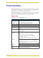
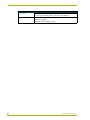
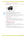
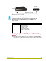
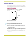
instruction manual
AXR-NWS
NetWave Server
C o n t r o l Pa n e l A c c e s s o r i e s
AMX Limited Warranty and Disclaimer
AMX Corporation warrants its products to be free of defects in material and workmanship under normal use for
three (3) years from the date of purchase from AMX Corporation, with the following exceptions:
•
Electroluminescent and LCD Control Panels are warranted for three (3) years, except for the display and touch
overlay components that are warranted for a period of one (1) year.
•
Disk drive mechanisms, pan/tilt heads, power supplies, MX Series products, and KC Series products are
warranted for a period of one (1) year.
•
Unless otherwise specified, OEM and custom products are warranted for a period of one (1) year.
•
Software is warranted for a period of ninety (90) days.
•
Batteries and incandescent lamps are not covered under the warranty.
This warranty extends only to products purchased directly from AMX Corporation or an Authorized AMX Dealer.
AMX Corporation is not liable for any damages caused by its products or for the failure of its products to perform.
This includes any lost profits, lost savings, incidental damages, or consequential damages. AMX Corporation is not
liable for any claim made by a third party or by an AMX Dealer for a third party.
This limitation of liability applies whether damages are sought, or a claim is made, under this warranty or as a tort
claim (including negligence and strict product liability), a contract claim, or any other claim. This limitation of
liability cannot be waived or amended by any person. This limitation of liability will be effective even if AMX
Corporation or an authorized representative of AMX Corporation has been advised of the possibility of any such
damages. This limitation of liability, however, will not apply to claims for personal injury.
Some states do not allow a limitation of how long an implied warranty last. Some states do not allow the limitation or
exclusion of incidental or consequential damages for consumer products. In such states, the limitation or exclusion of
the Limited Warranty may not apply. This Limited Warranty gives the owner specific legal rights. The owner may
also have other rights that vary from state to state. The owner is advised to consult applicable state laws for full
determination of rights.
EXCEPT AS EXPRESSLY SET FORTH IN THIS WARRANTY, AMX CORPORATION MAKES NO
OTHER WARRANTIES, EXPRESSED OR IMPLIED, INCLUDING ANY IMPLIED WARRANTIES OF
MERCHANTABILITY OR FITNESS FOR A PARTICULAR PURPOSE. AMX CORPORATION
EXPRESSLY DISCLAIMS ALL WARRANTIES NOT STATED IN THIS LIMITED WARRANTY. ANY
IMPLIED WARRANTIES THAT MAY BE IMPOSED BY LAW ARE LIMITED TO THE TERMS OF THIS
LIMITED WARRANTY.
Table of Contents
Table of Contents
Product Information .................................................................................................1
Specifications .................................................................................................................... 1
Installation .................................................................................................................3
Setting the Group Address ................................................................................................ 4
Setting the GROUP ADDRESS DIP switch ............................................................................. 5
Setting the Device Address on a touch panel .......................................................................... 5
Setting the Group ID.......................................................................................................... 6
Setting Group ID DIP switches................................................................................................. 6
Setting the Group ID on the touch panel.................................................................................. 6
Connecting to the Controller.............................................................................................. 7
Power guidelines...................................................................................................................... 7
Using AXlink for data and power.............................................................................................. 7
Using AXlink for data with an auxiliary power supply............................................................... 8
Preparing captive wires............................................................................................................ 8
Installing the Control System............................................................................................. 8
Installing the Optional NWA-EXT External Extended Range Antenna.............................. 9
Firmware Upgrades ................................................................................................11
Replacing the Firmware Chip .......................................................................................... 11
AXR-NWS NetWave Server
i
Table of Contents
ii
AXR-NWS NetWave Server
Product Information
Product Information
The AXR-NWS NetWave Server is a two-way Radio Frequency (RF) device employing 2.4 GHz
digital communications. The AXR-NWS is compatible with both Axcess and NetLinx Integrated
Central Controllers, and communicates with up to 16 wireless devices.
The AXR-NWS complies with Part 15 of the FCC Rules. Operation is subject to the following two
conditions: (1) this device may not cause harmful interference and (2) this device must accept any
interference received, including interference that may cause undesired operation.
Specifications
The following table lists the AXR-NWS specifications.
Specifications
Dimensions (HWD)
NWS without antenna
1.65" x 5.55" x 6.40" (4.19 cm x 14.10 cm x 16.20 cm)
NWS with antenna
7.41" x 5.55" x 6.40" (18.82 cm x 14.10 cm x 16.20 cm)
Faceplate
1.50" x 5.55" x 0.53" (3.80 cm x 14.10 cm x 1.30 cm)
Weight
10.56 oz (299.37 g)
Power Requirement
175 mA @ 12 VDC
Enclosure
Metal with black anodized matte finish
Operating Frequency
2.4 GHz RF digital spread-spectrum transmission and reception with up to 16
ViewPoints
Control Compatibility
Axcess Central Controllers
NetLinx Central Controllers
Landmark Controller
Front Panel Components:
AXlink LED
Green LED that shows power and AXlink communication activity. Blink patterns
include:
• Off - No power or the controller is not functioning properly.
• One blink per second - indicates power is active and AXlink data
communication is functional.
• Full On - Indicates power is active and AXlink data communication is not
functional.
Status LED
Red LED that lights when an RF link is established with one or more devices.
• If the light is On, the Server’s signal is locked and communicating with the
ViewPoint.
• If the light is Off, the Server is not communicating with the ViewPoint because
the signal is either lost or broken.
RX LED
Yellow LED that lights when the AXR-NWS receives RF control data.
Group Address
8 position DIP switch that sets the GROUP ADDRESS (0 - 255)
Group ID
4 position DIP switch that sets the control group identification (0 - 15)
Rear Panel Components:
Antenna
AXR-NWS NetWave Server
Omni-directional, swivel high-gain RF antenna
1
Product Information
Specifications (Cont.)
Connectors
Optional Accessories:
4-pin (male) AXlink, 3.5 mm, bus connector; connects to the Central Controller
for receiving and transmitting AXlink control data and 12 VDC power.
• AC-RK Rack Mount Kit
• PSN2.8 Power Supply
• NWA-EXT (External Netwave Antenna)
2
AXR-NWS NetWave Server
Installation
Installation
Before installing the wireless communications equipment, the AXR-NWS GROUP ADDRESS and
GROUP ID DIP switches must be set.
The AXR-NWS can be installed on any flat surface. Avoid installations that place the AXR-NWS
inside an equipment rack where the transmission/reception is hindered. Placing the AXR-NWS
above equipment, with no obstructions to the antenna, is best for peak performance.
Each AXR-NWS is capable of distributing a maximum of 16 Device Addresses, in any
combination, to communicating ViewPoint touch panels.
The AXR-NWS allows a maximum control of 1020 channels. An example is shown in FIG. 1.
Device #2
255 channels
Device #3
255 channels
Device #4
255 channels
ViewPoint
(Device #1)
255 channels
Device
Address
128-131
Device
Address
132-135
Device
Address
136-139
255 channels per device
for a max. of 1020 per
touch panel
Device
Address
140-143
GROUP ID
(0 - 15)
ViewPoint
Touch Panels
*16 possible Device Addresses
available to communicating
ViewPoints.
GROUP ADDRESS
(1 - 255)
NXI Integrated
Controller
(rear view)
Television
VCR
Television
FIG. 1 AXR-NWS control compatibility
The AXR-NWS only appears on the bus when communication with a ViewPoint;
otherwise, it is never visible.
AXR-NWS NetWave Server
3
Installation
Setting the Group Address
You must remove the translucent faceplate on the front panel before you can access the DIP
switches. The GROUP ADDRESS DIP switch sets the starting address for the device numbers. For
example, if the GROUP ADDRESS DIP switch is set to 128, the AXR-NWS communicates with
device numbers 128 - 143.
Device numbers for ViewPoint touch panels can range from 0 - 255, but typically begin at 128; they
are set within the ViewPoint’s protected setup page. Refer to the instruction manual supplied with
you touch panel for detailed information. The table below lists the DIP switch values.
Group Address DIP
Switch Values
Switch
Value
1
1
2
2
3
4
4
8
5
16
6
32
7
64
8
128
The GROUP ID DIP switch sets the identification number to synchronize communication between
the wireless devices and AXR-NWS. Each AXR-NWS must have a unique GROUP ID number. All
ViewPoints must match the four-position DIP switch on the AXR-NWS. FIG. 2 illustrates the
relationship between Group Address and Device Address.
Group Address #128
Group ID #0
Device Addresses
Address
#128
Address
#143
Group Address #144
Group ID #1
Device Addresses
Address
#144
Address
#159
FIG. 2 Relationship between Group Address and Device Address
To use 32 wireless devices, use two AXR-NWS Servers set to two different Group IDs. The first
Server is set to GROUP ID # that supplies the addresses 128 - 143. The second Server is set to the
GROUP ID# that supplies the addresses 144 - 159.
4
AXR-NWS NetWave Server
Installation
Setting the GROUP ADDRESS DIP switch
You must remove the translucent faceplate on the front panel before you can access
the DIP switches.
1. Determine the number of devices to control.
2. Allocate the device address range in sets of 16 (touch panel addresses can range from 0 - 255,
but typically begin at 128).
3. Verify device address values are not already assigned to other devices.
4. Verify the device assignments fall within the range assigned for each Server (numerical range
for any given AXR-NWS Group Address is 16).
5. Use the DIP switch values shown in Group Address DIP Switch Values table on page 4 to set
the address of the first device for the group address range on the Server.
6. Use the DIP switch program, on AMX’s Control CD, to determine the DIP switch arrangement
for a given value.
7. Enter the DIP switch value into the Device Number field, and the DIP switch on the right
shows the corresponding switch arrangement.
8. Set the GROUP ADDRESS DIP switch on the AXR-NWS to begin at the value assigned to the
first device.
Setting the Device Address on a touch panel
1. Press SETUP on the Main page of the touch panel.
2. Press PROTECTED SETUP on the Setup page to open the password keypad.
3. Enter 1988 (default password) in the keypad and press ENTER to open the Protected Setup
page, shown in FIG. 3. If you enter a wrong number, press CLEAR and re-enter the number.
FIG. 3 ViewPoint protected setup page
4. Press DEVICE BASE to open the numeric keypad.
5. Set the base address value for the touch panel and press ENTER. The base address range is
1 - 255.
If four devices are used, and the base address is 128, the touch panel occupies
device numbers 128 - 131.
AXR-NWS NetWave Server
5
Installation
6. Press DEVICE USED to open the keypad and set the panel’s device number (1 - 4). Each
device number supports up to 255 programmable channel codes.
7. Press ENTER twice to save the new values and return to the Main page.
Setting the Group ID
The four-position GROUP ID DIP switch sets the identification number to enable communication
between the wireless devices and the AXR-NWS. Each AXR-NWS must have a unique GROUP
ID. The maximum number of control devices connecting to an AXR-NWS is 16. The Group ID
DIP switch setting must be identical on the AXR-NWS and all ViewPoints communicating with it.
For example, if the AXR-NWS GROUP ADDRESS DIP switch is set to 128 and the GROUP ID
DIP switch is set to 1, the ViewPoint devices 128 - 143 must have their GROUP ID set to 1. If the
AXR-NWS GROUP ID number does not match the ViewPoint GROUP ID, they will not
communicate properly. The table below lists the Group ID DIP switch values.
Group ID DIP Switch Values
Switch
Value
1
1
2
2
3
4
4
8
Setting Group ID DIP switches
You must remove the translucent faceplate on the front panel before you can access
the DIP switches.
1. Determine the number of devices to be controlled.
2. Verify the desired device number values are not assigned to another device.
3. Determine the number of AXR-NWS Servers needed to control the wireless devices. These
devices are assigned addresses in groups of 16; each group is then assigned a GROUP ID. Use
the DIP switch values shown in the above Group ID DIP Switch Values table to set the GROUP
ID on the Server.
Setting the Group ID on the touch panel
1. Press SETUP on the Main Page of the touch panel.
2. Press PROTECTED SETUP on the Setup page to open the password keypad.
3. Enter 1988 (default password) in the keypad and press ENTER to open the Protected Setup
page. If you enter a wrong number, press CLEAR and re-enter the number.
4. Press WIRELESS SETTINGS to open the page shown in FIG. 4.
5. Press UP or Down to set the Group ID value for the AXR-NWS. This value must match the
DIP switch value assigned on the Server.
6. Press EXIT to save the changes and exit from the Wireless Settings page. Continue pressing
EXIT or return to the Main page.
6
AXR-NWS NetWave Server
Installation
FIG. 4 ViewPoint wireless settings page
Connecting to the Controller
Power guidelines
The AXR-NWS requires 12 VDC power to operate properly. Power is supplied by the control
system’s AXlink cable. The maximum wiring distance between the Controller and Server is
determined by power consumption, available voltage, and cable wire gauge. The following table
lists wire size and maximum lengths allowable between the AXR-NWS and the Central Controller.
Maximum wiring lengths are based on a minimum of 13.5 volts available at the control system’s
power supply output.
Wiring Guidelines
Wire Size
Maximum Wiring Length
18 AWG
670.69 ft. (204.42 m)
20 AWG
424.33 ft. (129.33 m)
22 AWG
264.55 ft. (80.63 m)
24 AWG
166.76 ft. (50.83 m)
Servers should not be located within 10 ft. of each other. Do not connect power to the
AXR-NWS until wiring is complete.
Do not install the AXR-NWS farther away from the control system than recommended
in the Wiring Guidelines table.
Using AXlink for data and power
Connect the AXlink connector to the AXlink port on the rear of the AXR-NWS for data and power
(FIG. 5), using mini- and standard 4-pin captive-screw type connectors.
PWR (+)
AXR-NWS
AXP
(3.5 mm connector) AXM
GND (-)
PWR (+)
AXP
AXM
GND (-)
Central Controller
AXlink connector on the Controller
FIG. 5 AXlink wiring diagram
AXR-NWS NetWave Server
7
Installation
Using AXlink for data with an auxiliary power supply
Connect the Controller’s AXlink connector to the AXlink connector on the rear panel of the AXRNWS, as shown in FIG. 6.
PWR (+)
12 VDC power supply
GND (-)
PWR (+)
AXP
AXM
GND (-)
PWR (+)
AXP
AXM
GND (-)
Controller
AXR-NWS (3.5 mm connector)
FIG. 6 AXlink and 12 VDC power supply wiring diagram
If you are not using power from AXlink, disconnect the wiring from the Controller
before wiring the AXR-NWS. Make sure the auxiliary power supply’s PWR (+) is not
connected to the Central Controller’s AXlink connector.
Use an auxiliary 12 VDC power supply when the distance between the Central Controller and
Server exceeds the limits described in Wiring Guidelines table. Connect only the GND (-) wire on
the AXlink connector when using an auxiliary 12 VDC power supply.
Preparing captive wires
1. Strip 0.25" of wire insulation off the ends of all wires.
2. Insert each wire end into the appropriate opening on the connector according to the wiring
diagrams and connector types described in theUsing AXlink for data and power section on
page 7. Do not tighten the screws excessively; doing so may strip threads and damage the
connector.
Installing the Control System
1. Install the AXR-NWS on any flat surface.
2. Rotate the RF antenna to a vertical position to communicate with the touch panels.
3. Verify that the Server DIP switch settings are configured with the correct GROUP ADDRESS
and GROUP ID.
4. Verify the touch panels have the same GROUP ID value as the Server.
5. Connect the Server to the Central Controller (FIG. 7) by connecting the 3.5 mm 4-pin AXlink
cable from the bus connector to the AXlink connector at the rear of the Central Controller.
8
AXR-NWS NetWave Server
Installation
AXR-NWS
(rear view)
Controller
(rear view)
Mini AXlink connector (3.5 mm)
FIG. 7 AXR-NWS connection to a Controller
The AXR-NWS does not support devices which previously used the AXR-WAVES
server. AXR-NWS uses a 2.4 GHz digital spread spectrum to avoid common
problems associated with RF control. However, avoid placing the AXR-NWS
components next to microwave ovens, spread-spectrum, consumer microwave video
link transceivers, projectors using Halide/Xenon lamps, or AXR-WAVES Server
(at least 10 ft. away).
Specifications for the Optional NWA-EXT
NWA-EXT
(External Netware Antenna)
• 6 ft coax with various connectors allow maximum flexibility in placement
• 1/2 wave coaxial dipole
• Frequency: 2.4-2.5 GHz
• Polarization: Vertical
• Nominal Impedence: 50 ohms
• VSWR 1.5:1 max at resonance
• RF Power Handling: 50 watts
• Temperature Range: -40ºC to +85ºC
Installing the Optional NWA-EXT External Extended Range
Antenna
1. Unscrew the extended range antenna (that comes shipped with the AXR-NWS) from the rear
coaxial connector on the NWS unit by twisitng the connector is a counter-clockwise direction.
2. Connect the NWA-EXT antenna to the rear of the NWS by inserting the terminal coaxial
connector and twisting it in a clockwise direction.
Verify that the antenna is not being obstructed by any other device or receiving interference
form anothersource.
AXR-NWS NetWave Server
9
Installation
10
AXR-NWS NetWave Server
Firmware Upgrades
Firmware Upgrades
Firmware upgrades allow you to install the latest available operating system for the AXR-NWS.
You will need a Phillips screwdriver and a non-conducting flat-blade tool to slip under the installed
firmware IC to lift it up and out of the IC socket.
Replacing the Firmware Chip
1. Disconnect the AXlink connector (FIG. 8) from the rear of the AXR-NWS.
AXlink connector
(3.5 mm)
High-Gain antenna
Alignment slot
Firmware socket
FIG. 8 AXR-NWS circuit board and IC socket location
2. Using a small Phillips-head screwdriver, remove the two screws on the rear side of the
AXR-NWS housing.
Ground yourself before touching anything within the AXR-NWS housing. Damage
may occur to the components mounted on the circuit board if you retain a static
electric charge.
3. Unscrew the antenna in a counter-clockwise direction and remove it from the rear connector.
4. Slide the rear plate/circuit board assembly out of the AXR-NWS housing.
5. Pry the firmware chip from its socket by placing a non-conducting, flat-blade tool between the
firmware chip and its mounting socket.
6. Place the new firmware chip in the mounting socket. Ensure the pins on the firmware chip and
the socket slots are aligned correctly. Apply sufficient pressure to the chip to seat it in the
socket.
7. Replace the rear plate/circuit board assembly and secure the rear plate using the two screws
removed in step 2.
AXR-NWS NetWave Server
11
Firmware Upgrades
8. Secure the antenna to the rear coaxial connector in a counter-clockwise direction.
Refer to the Installing the Optional NWA-EXT External Extended Range Antenna section on
page 9 for more detailed information on connecting the optional external antenna.
12
AXR-NWS NetWave Server
Installation
AXR-NWS NetWave Server
13
brussels • dallas • los angeles • mexico city • philadelphia • shanghai • singapore • tampa • toronto* • york
3000 research drive, richardson, TX 75082 USA • 469.624.8000 • 800.222.0193 • fax 469.624.7153 • technical support 800.932.6993
042-004-2258 5/03 ©2003 AMX Corporation. All rights reserved. AMX, the AMX logo, the building icon, the home icon, and the light bulb icon are all trademarks of AMX Corporation.
AMX reserves the right to alter specifications without notice at any time. *In Canada doing business as Panja Inc.
AMX reserves the right to alter specifications without notice at any time.