1
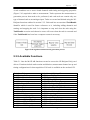
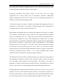
The Enhancement of a MultiTerrain Mechatron for
Autonomous Outdoor
Applications
A thesis
submitted in partial fulfilment
of the requirements for the Degree
of
Master of Science in
Physics and Electronic Engineering
at the
University of Waikato
by
Christopher Luke Cawley
2006
ii
The Enhancement of a Multi-Terrain Mechatron for Autonomous Outdoor Applications
Abstract
iii
ABSTRACT
Medium scale robotic vehicles which are easily portable by humans are achieving
increased application as technology improves, particularly in certain outdoor
environments. Conventional, manually operated equipment has difficulty traversing
uneven terrain, such as in dangerous environments where the human operators may be
at risk. Robots which are capable of autonomous operation can be used in place of
traditional machinery to perform repetitive or difficult tasks thus reducing the risk to
the human operators and increasing the overall productivity by operating for longer
time periods. This thesis discusses the modification and enhancement of a multiterrain robotic vehicle that will eventually be capable of autonomous operation.
The mechanical platform consists of a track-laying differential drive system
supporting payloads in excess of 100 kg which was previously developed by the
Mechatronics Group at the University of Waikato. The existing shell did not have any
working systems onboard so a complete design and installation of the electronics has
been completed and various sensory systems are evaluated and implemented. The
required control and navigation software systems have been designed enabling robot
control in an outdoor environment. The mechatron and the installed systems have
been successfully tested in a variety of outdoor conditions.
iv
The Enhancement of a Multi-Terrain Mechatron for Autonomous Outdoor Applications
Acknowledgements
v
ACKNOWLEDGEMENTS
The support and assistance throughout this project from the following people are
greatly appreciated and thus require acknowledgement.
To Dr Dale Carnegie, my project supervisor and valued lecturer during undergraduate
studies who made this project available for undertaking. The invitation to graduate
level study and continued support and guidance throughout this project is greatly
appreciated.
Assistance by the Physics Department technical staff during the project in all aspects
of electronic and mechanical design was always willingly provided. Special thanks to
Scott Forbes and Bruce Rhodes for their knowledge and humour throughout my time
at Waikato.
My fellow graduate students deserve no less appreciation for their ability to discuss
concepts and provide valued knowledge making the work environment interesting and
supportive. Thanks in particular to Jason Edwards, Praneel Chand, and Chris LeeJohnson.
Finally a special thank you to all of my family for your continued support and
encouragement throughout my university studies, without which my success to date
would not have been possible.
vi
The Enhancement of a Multi-Terrain Mechatron for Autonomous Outdoor Applications
Table of Contents
vii
TABLE OF CONTENTS
ABSTRACT................................................................................................................ iii
ACKNOWLEDGEMENTS ........................................................................................v
TABLE OF CONTENTS ..........................................................................................vii
LIST OF FIGURES ................................................................................................. xiii
LIST OF TABLES ....................................................................................................xix
1.
1.1
1.2
1.3
1.4
1.5
INTRODUCTION................................................................................................1
MOTIVATION FOR SYSTEM DEVELOPMENT..............................................1
COMMERCIAL APPLICATIONS .......................................................................2
PROJECT SPECIFICATIONS..............................................................................3
PROJECT PLANNING .........................................................................................4
THESIS STRUCTURE..........................................................................................5
2. BACKGROUND ..................................................................................................7
2.1 PREVIOUS MECHATRONICS RESEARCH........................................................7
2.2 RESEARCH OF CURRENT SYSTEMS................................................................8
2.2.1 TALON™ .........................................................................................................9
2.2.2 ACER................................................................................................................9
2.2.3 MATILDA Robotic Platform .........................................................................10
2.2.4 PackBot ...........................................................................................................11
2.2.5 Urbie ...............................................................................................................11
2.2.5 Other robots ....................................................................................................12
2.3 EXISTING PLATFORM.......................................................................................13
2.3.1 Drive Motors...............................................................................................14
2.3.2 Drive System Type .....................................................................................15
2.3.3 Advantages of Skid Steering.......................................................................17
2.3.4 Disadvantages of Skid Steering ..................................................................17
2.3.5 Existing Onboard Hardware .......................................................................19
2.4 PROCESSOR ARCHITECTURE .........................................................................20
2.4.1 Embedded Controller ..................................................................................21
2.4.2 FPGA ..........................................................................................................21
2.4.3 Handheld PC ...............................................................................................21
2.4.4 Laptop Computer ........................................................................................21
2.4.5 Full Size PC ................................................................................................22
2.4.6 ShuttleX PC ................................................................................................22
2.4.7 Selected Architecture ..................................................................................22
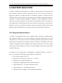
2.5 ELECTRONICS POWER SUPPLY .....................................................................23
2.6 BATTERY SELECTION ......................................................................................24
2.6.1 Required Specifications ..............................................................................24
2.6.2 Review of Battery Types ............................................................................25
2.6.3 Battery Ratings............................................................................................26
2.6.4 Selected Batteries........................................................................................27
2.6.5 Charging Procedure ....................................................................................28
2.7 DATA ACQUISITION CARD..............................................................................29
2.8 OTHER HARDWARE COMPONENTS ..............................................................31
viii The Enhancement of a Multi-Terrain Mechatron for Autonomous Outdoor Applications
2.8.1 Wireless Network Adapters ........................................................................31
2.8.2 Onboard Video Camera ..............................................................................32
2.8.3 Infrared Proximity Detectors ......................................................................33
2.8.4 Electronic Compass ....................................................................................33
2.8.5 GPS Receiver ..............................................................................................34
2.8.6 Inertial Sensor .............................................................................................35
2.8.7 Motor Drivers..............................................................................................35
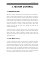
3. MOTOR CONTROL.........................................................................................37
3.1 INTRODUCTION .................................................................................................37
3.1.1 DC Motor Theory ...........................................................................................37
3.1.2 Possible Solutions ...........................................................................................38
3.1.3 Differential Drive Motor Control ...................................................................40
3.2 EXISTING MOTOR DRIVERS............................................................................41
3.2.1 Outdoor Mechatron.........................................................................................41
3.2.2 Co-operating Robots .......................................................................................42
3.2.3 Marvin.............................................................................................................43
3.2.4 Underwater ROV ............................................................................................43
3.3 GENERIC MOTOR DRIVERS.............................................................................43
3.3.1 Project Outline ................................................................................................44
3.3.2 Hardware Components....................................................................................45
3.3.3 Software Interface...........................................................................................47
3.3.4 Testing and Evaluation ...................................................................................48
3.3.5 Modifications ..................................................................................................50
Mounting Enclosure.............................................................................................50
PWM Frequency ..................................................................................................51
Shielding ..............................................................................................................52
Smoothing Capacitors..........................................................................................52
Ferrite Beads ........................................................................................................52
RFI Suppression Choke .......................................................................................53
3.3.6 Summary .........................................................................................................54
3.4 REVIEW OF COMMERCIAL SYSTEMS...........................................................55
3.4.1 MAXI Motor Driver Kit .................................................................................56
3.4.2 MD03 and MD22............................................................................................57
3.4.3 Tecel D200......................................................................................................58
3.4.4 MDM5253.......................................................................................................59
3.4.5 RoboteQ AX2550 ...........................................................................................60
3.5 SELECTED MODULES .......................................................................................61
3.5.1 Features ...........................................................................................................62
3.5.2 Interfacing .......................................................................................................64
3.5.3 Handheld Controller........................................................................................66
3.5.4 Programming...................................................................................................66
3.5.5 Status Codes....................................................................................................68
3.5.6 Robot Mounting ..............................................................................................69
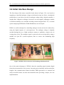
3.6 Initial Interface Design ..........................................................................................70
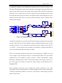
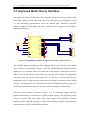
3.7 Improved Motor Driver Interface ..........................................................................72
3.8 MICROCONTROLLER ........................................................................................75
3.8.1 Selected Controller..........................................................................................76
3.8.2 Power Supply ..................................................................................................77
3.8.3 Memory Configuration ...................................................................................77
Table of Contents
ix
3.8.4 Programming...................................................................................................78
3.8.5 DAQ Card Interface........................................................................................78
3.8.6 Motor Driver Interface....................................................................................80
3.9 RADIO CONTROL ...............................................................................................81
4. ELECTRONICS AND SENSORS....................................................................83
4.1 CENTRAL COMPUTER ......................................................................................83
4.1.1 Installation.......................................................................................................83
4.1.2 Hard Drive Support.........................................................................................84
4.1.3 Communication Interfaces ..............................................................................85
4.2 POWER SYSTEM.................................................................................................85
4.2.1 Fuse Box .........................................................................................................86
4.2.2 Wiring .............................................................................................................86
4.2.3 Power Switch Panel ........................................................................................87
4.2.4 Power Distribution Board ...............................................................................88
4.3 SENSOR OPTIONS ..............................................................................................89
4.3.1 Requirements ..................................................................................................89
4.3.2 Positioning ......................................................................................................90
4.3.2 Ranging ...........................................................................................................91
4.3.4 Other sensors...................................................................................................91
4.4 ELECTRONIC COMPASS ...................................................................................92
4.4.1 Previous Module .............................................................................................92
4.4.2 Review of Available Modules ........................................................................93
KVH C100 Compass Engine ...............................................................................93
CMPS03...............................................................................................................94
Handheld Units ....................................................................................................95
Honeywell HMR3000..........................................................................................95
True North Revolution.........................................................................................96
TruePoint Compass Module ................................................................................96
4.4.3 Selected Module..............................................................................................98
4.4.4 Interface Design ..............................................................................................99
4.4.5 Mounting Enclosure......................................................................................100
4.5 GPS ......................................................................................................................101
4.5.1 Background ...................................................................................................101
4.5.2 Receiver ........................................................................................................103
4.6 ACCELEROMETER...........................................................................................104
4.6.1 Advantages....................................................................................................105
4.6.2 Device Specifications....................................................................................105
4.6.3 Theory of Operation......................................................................................106
4.6.4 Sensitivity .....................................................................................................107
4.6.5 Interface Design ............................................................................................108
4.6.6 Measuring Tilt...............................................................................................109
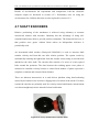
4.7 SHAFT ENCODERS...........................................................................................110
4.8 INFRARED SENSORS .......................................................................................111
4.8.1 Operation.......................................................................................................111
4.8.2 Sensor Response ...........................................................................................112
4.8.3 Range Calculation.........................................................................................113
4.8.4 Mounting.......................................................................................................115
4.9 DAQ CARD CONNECTOR MODULE .............................................................118
4.10 ELECTRONICS ENCLOSURE........................................................................120
x
The Enhancement of a Multi-Terrain Mechatron for Autonomous Outdoor Applications
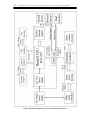
4.11 HARDWARE SUMMARY...............................................................................121
5. SOFTWARE.....................................................................................................123
5.1 APPLICATION REVIEW...................................................................................123
5.1.1 LabVIEW......................................................................................................124
5.1.2 Visual C++....................................................................................................125
5.1.3 Visual Basic ..................................................................................................126
5.1.4 Java ...............................................................................................................127
5.1.5 MATLAB......................................................................................................128
5.1.6 Linux .............................................................................................................128
5.1.7 Selected Software Platform...........................................................................128
5.2 WIRELESS NETWORK .....................................................................................130
5.2.1 Login Procedure............................................................................................130
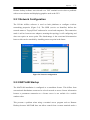
5.2.1 Network Configuration .................................................................................131
5.2.3 MATLAB Startup .........................................................................................131
5.3 DAQ CARD INTERFACE..................................................................................132
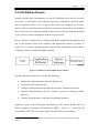
5.3.1 DAQ Toolbox ...............................................................................................132
5.3.2 NI-DAQmx Drivers ......................................................................................133
5.3.3 DLL Interface to NI-DAQmx .......................................................................134
5.3.4 Channels and Tasks.......................................................................................136
5.3.5 Available Functions ......................................................................................137
5.3.6 MAX Studio..................................................................................................138
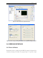
5.4 COMPASS INTERFACE....................................................................................139
5.4.1 Demo Software .............................................................................................139
5.4.2 Connection ....................................................................................................140
5.4.3 Data Collection .............................................................................................141
5.4.4 Configuration and Calibration ......................................................................143
5.5 GPS INTERFACE ...............................................................................................144
5.6 OTHER HARDWARE INTERFACES...............................................................146
5.6.1 Rangefinders .................................................................................................146
Mean ..................................................................................................................147
Weighted Mean..................................................................................................147
Median ...............................................................................................................148
Selected Method.................................................................................................148
5.6.2 Encoders........................................................................................................149
5.6.3 Accelerometer ...............................................................................................150
5.6.4 Video Camera ...............................................................................................151
5.7 SYSTEM CONFIGURATION............................................................................152
5.7.1 Timers/Callbacks ..........................................................................................152
5.7.2 Persistent Variables.......................................................................................153
5.7.3 Low Level Control Loop ..............................................................................154
5.7.4 DAQ Safety Pulse .........................................................................................156
5.7.5 Navigation Control Loop ..............................................................................156
5.7.6 Data log Files ................................................................................................157
5.8 MECHATON CONTROL ...................................................................................158
5.8.1 Velocity Control............................................................................................158
5.8.2 Heading Control............................................................................................160
5.8.3 Obstacle Avoidance ......................................................................................161
5.8.4 Navigation.....................................................................................................161
5.9 MICROCONTROLER CODE.............................................................................162
Table of Contents
xi
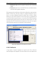
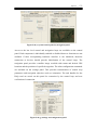
5.10 USER INTERFACE ..........................................................................................166
5.10.1 GUIDE ........................................................................................................167
5.10.2 TabPanels....................................................................................................168
6. RESULTS & CONCLUSION.........................................................................173
6.1 CURRENT CONSUMPTION .............................................................................173
6.2 ACCELEROMETER...........................................................................................177
6.2.1 Stationary Readings ..................................................................................177
6.2.2 Collision Detection ...................................................................................178
6.2.3 Tilt Measurements ....................................................................................180
6.3 ELECTRONIC COMPASS .................................................................................182
6.4 GPS EVALUATION ...........................................................................................184
6.4.1 Positioning ................................................................................................184
6.4.2 Heading .....................................................................................................185
6.4.3 Long Term GPS Response........................................................................186
6.4.4 Improving GPS Positioning ......................................................................189
6.4.5 GPS Deficiencies ......................................................................................190
6.5 ROBOT MOTION ...............................................................................................190
6.5.1 Motor Operation........................................................................................191
6.5.2 Automatic Heading Control......................................................................192
6.5.3 Obstacle Avoidance ..................................................................................193
6.6 INITIAL FIELD TRIAL......................................................................................193
6.7 TESTING OUTDOORS ......................................................................................195
6.8 FUTURE WORK.................................................................................................196
6.9 SUMMARY.........................................................................................................197
GLOSSARY..............................................................................................................199
REFERENCES.........................................................................................................201
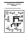
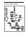
APPENDIX A: CIRCUIT DESIGN .......................................................................203
A.1 MOTOR DRIVER INTERFACE BOARD ........................................................203
A.2 MICROCONTROLLER BOARD ......................................................................204
A.3 ELECTRONIC COMPASS INTERFACE .........................................................205
A.4 GPS INTERFACE ..............................................................................................206
A.5 ACCELEROMETER BOARD ...........................................................................207
APPENDIX B: CD CONTENTS ............................................................................209
xii
The Enhancement of a Multi-Terrain Mechatron for Autonomous Outdoor Applications
List of Figures
xiii
LIST OF FIGURES
Figure 1.1: Robots used in dangerous environments. ……………………………….1
Figure 2.1: Fleet of mobile robots within Mechatronics Group...……… ……...……7
Figure 2.2: TALON military robot……………………………… ……………..……9
Figure 2.3: ACER robot………………………………………………………….…10
Figure 2.4: MATILDA tracked robot………………….………… …………...……10
Figure 2.5: Packbot…………………………………………………………...….…11
Figure 2.6: Urban reconnaissance robot …………………… …………………..…12
Figure 2.7: Collection of multi-terrain robots……………………… .......……...…12
Figure 2.8: Existing robot platform at project onset……………… ………………13
Figure 2.9: Drive motors from Dynamic Mobility………………… ………..….…14
Figure 2.10: Typical motor performance characteristics………………………..…14
Figure 2.11: Underside of mechatron illustrating concept of differential drive…...16
Figure 2.12: Tracked vehicle negotiating difficult terrain…………… …………...17
Figure 2.13: Skid steering on spot showing track movement and frictional forces. 18
Figure 2.14: Original microcontroller board and PC motherboard………… ……..19
Figure 2.15: Original power supply consisting of UPS and ATX converter… …...19
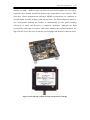
Figure 2.16: Small form factor ShuttleX PC………………………… ……………22
Figure 2.17: Olympic OTC-1000A UPS and ACE-828C ATX supply…… …..….23
Figure 2.18: Hella Endurant battery………………………………… ………….…27
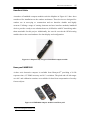
Figure 2.19: National Instruments PCI-6229M DAQ Card……………… …….…30
Figure 2.20: Wireless network adapters …………………………………… …..….32
Figure 2.21: Logitech QuickCam Pro 4000 webcam…………………… ……..….32
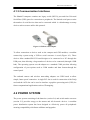
Figure 2.22: Sharp GP2Y0A02YK infrared sensor ………………………...…...…33
Figure 2.23: Honeywell HMR3300 electronic compass module…………… …..…34
Figure 2.24: Motorola M12+ Oncore GPS Receiver…………………… …………34
Figure 2.25: MMA7260Q 3-axis accelerometer …………………………… .....….35
Figure 2.26: Rhino DS72K motor driver module……………………………….…35
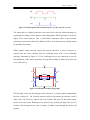
Figure 3.1: PWM signals and transmitted power………………………… …..……39
Figure 3.2: H-Bridge switching topography………………………………………..39
Figure 3.3: Differential drive configuration consists of two opposing motors… .....40
xiv The Enhancement of a Multi-Terrain Mechatron for Autonomous Outdoor Applications
Figure 3.4: Simplified single switch and relay drive circuit………………… …….41
Figure 3.5: Itchy and Scratchy motor drivers……………………………… ………42
Figure 3.6: One of the H-Bridge power circuit boards previously designed… ……45
Figure 3.7: Previously designed microcontroller board………………… …………46
Figure 3.8: Initial motor driver front end GUI…………………… ……………..…47
Figure 3.9: Small 24 V motor driver test motor………………………… ………....48
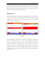
Figure 3.10: Clean and noisy 5 V supply rail…………………………… ……...….49
Figure 3.11: Noise from PWM at 34.72 kHz and PWM signal……………… …....49
Figure 3.12: Mounting enclosure and cooling fans for motor driver………… ……50
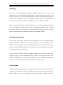
Figure 3.13: Noise after PWM changed to 12 kHz……………………… ………...51
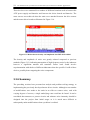
Figure 3.14: Inspection of single noise pulse (f ≈ 20 MHz)………………………..53
Figure 3.15: C215 RFI noise suppression choke and connection diagram………....53
Figure 3.16: Reduced noise density and amplitude after RFI choke added…… …..54
Figure 3.17: Assembled Modotronics MAXI motor driver kit……… …………….56
Figure 3.18: MDO3 and MD22 motor drivers………………………… …………..57
Figure 3.19: Tecel Microcontrollers D200 DC Motor Driver Board……… ………58
Figure 3.20: MDM5253 motor driver board…………………… ………………….59
Figure 3.21: RoboteQ AX2550 controller module.………………………………...60
Figure 3.22: RHINO DS72K controller dimensions……………… …………….....62
Figure 3.23: Example scooter tiller head from Dynamic Controls Ltd…… ……….64
Figure 3.24: RHINO suggested wiring diagram……………………… …………...65
Figure 3.25: Handheld motor driver controller………………………… ………….66
Figure 3.26: Connection of handheld programmer to RHINO controller…… …….67
Figure 3.27: RHINO controllers mounted on plate at rear of mechatron…………..69
Figure 3.28: Motor driver interface board utilizing PWM based DAC…… ………70
Figure 3.29: Simplified schematic of PWM interface board……………………….71
Figure 3.30: Simplified schematic of digital pot interface to motor drivers…… ….72
Figure 3.31: Schematic showing key switch control circuitry……………… ……..73
Figure 3.32: Microcontroller header and optoisolated status signals………… ……73
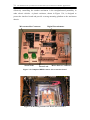
Figure 3.33: Completed RHINO motor driver interface board…………… …….…74
Figure 3.34: Mounting enclosure for motor driver interface…………………….…74
Figure 3.35: Microcontroller board for motor control……………………………...75
Figure 3.36: First microcontroller board and improved design………………….…76
Figure 3.37: Microcontroller power supply……………………………………...…77
List of Figures
xv
Figure 3.38: Radio Controller interface board……………………… …………..…81
Figure 3.39: Radio control handheld transmitter………………………………...…81
Figure 4.1: Computer installation – Original idea and revised option…… ……..…84
Figure 4.2: Protective hard drive cradle and mounting position……… ………...…84
Figure 4.3: USB to serial adapter…………………………………… …………..…85
Figure 4.4: Fuse enclosure……………………………………………………….…86
Figure 4.5: Subsection of wiring showing motor driver connection…… ……….…87
Figure 4.6: Power switch and charging panel…………………………………....…88
Figure 4.7: Power distribution board…………………………………………….…88
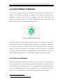
Figure 4.8: Earth's magnetic field………………………………………………..…92
Figure 4.9: Initial Vector2X compass and interface board……………………....…93
Figure 4.10: KVH C100………………………………………… ……………....…94
Figure 4.11: CMPS03 Low cost compass module……………… ……………....…94
Figure 4.12: MapStar fully integrated handheld compass module……………....…95
Figure 4.13: HMR3000 compass module from Honeywell……… …………..……95
Figure 4.14: TrueNorth Revolution compass module…………………………... …96
Figure 4.15: TruePoint compass module and protective housing………...….......…97
Figure 4.16: Axis of operation in a 3-axes compass module……… …………....…98
Figure 4.17: Compass module interface schematic…………… ……………….…100
Figure 4.18: Compass module protective enclosure…………………………....…100
Figure 4.19: Three GPS operation segments……………………… .……………..102
Figure 4.20: GPS antenna and receiver with interface board……… …………..…103
Figure 4.21: GPS receiver and interface board in protective case……………...…104
Figure 4.22: Capacitive sensing g-cells and ASIC………………… …………..…106
Figure 4.23: Beam and capacitor model of g-cells……………………..…………107
Figure 4.24: Suggested g-levels for various applications…………………………107
Figure 4.25: Accelerometer interface board and case……… .……………………108
Figure 4.26: Example of accelerometer tilt in Earth's gravity……….................…109
Figure 4.27: Newly manufactured encoder disks….…………… ……..………….110
Figure 4.28: Triangulation with infrared sensors…………… …………………....112
Figure 4.29: Infrared sensor response for different objects…………………….....113
Figure 4.30: MATLAB curve fitting toolbox for infrared sensor data………...….114
Figure 4.31: Infrared sensor locations……………………. ………………………116
Figure 4.32: Infrared sensor mounting brackets…………………………………..116
xvi The Enhancement of a Multi-Terrain Mechatron for Autonomous Outdoor Applications
Figure 4.33: Lateral sensing distance for different object ranges…………… …...117
Figure 4.34: Infrared based non-contact bumper…………………………… ……117
Figure 4.35: Infrared sensor interface boards……………………………………..118
Figure 4.36: Labelled terminal blocks…………………………………………….118
Figure 4.37: CB-68LPR terminal block and labelled connectors………………....119
Figure 4.38: NI-PCI6229 DAQ card connector pinout…………………… ……...119
Figure 4.39: Electronics enclosure………………………………………………...121
Figure 4.40: Block diagram overview of mechatron hardware…………… ……..122
Figure 5.1: Example LabView G code…………………………………… ………125
Figure 5.2: Typical Visual Basic development environment……………… …..…126
Figure 5.3: Remote Desktop Connection………………………………… ……....130
Figure 5.4: Network configuration………………………………… ………..……131
Figure 5.5: Position of NI-DAQmx driver software…………………… …..…….133
Figure 5.6: Load NI-DAQmx library into MATLAB…………………… …….....134
Figure 5.7: Unload NI-DAQmx library from MATLAB…………… ………..…..134
Figure 5.8: Excerpt from NI constants file………………………… …………..…135
Figure 5.9: Function call example…………………………………… ………...…135
Figure 5.10: Signal measurement and generation process……………...…………137
Figure 5.11: MAX Studio data acquisition interface………………… ……..……139
Figure 5.12: DAQ card test panels and power-up states configuration panel ….....139
Figure 5.13: HMR3300 demo software………………………………..………….140
Figure 5.14: Excerpt from compass initialization code…………………..……….141
Figure 5.15: Excerpt from compass disconnection code…………………..……...141
Figure 5.16: Compass_GetReading code extract…………… ……………..…..…142
Figure 5.17: Initialize compass callback…………………… …………..……...…142
Figure 5.18: Determine current compass data output mode.……………………...143
Figure 5.19: Example configuration function………………… ….....................…143
Figure 5.20: Storing GPS data into MATLAB structure………………...………..145
Figure 5.21: mas to degree conversion…………………………………..……..…146
Figure 5.22: Infrared sensor circular buffer shift……………… ………..……..…148
Figure 5.23: Encoder distance measurement………………………...…...……….149
Figure 5.24: Encoder velocity measurement………………… ……...…...…….…150
Figure 5.25: Accelerometer data acquisition for tilt calculation…… …...…......…151
Figure 5.26: Excerpt from camera connection code…………………...……….…151
List of Figures
xvii
Figure 5.27: Extract from image acquisition code ……………………………….152
Figure 5.28: Extract from low level control loop variable initialization …………155
Figure 5.29: Customization of individual hardware access functions…………….155
Figure 5.30: Excerpt from motor driver code showing safety pulse generation ….156
Figure 5.31: Unique data log file name creation ………………………………….157
Figure 5.32: Writing data to file using fprintf …………………………………….157
Figure 5.33: Use get() command to extract target velocity from sliders………….158
Figure 5.34: Heading error calculation for orientation control …………………...160
Figure 5.35: SPI code to send data word to digital potentiometer ………………..162
Figure 5.36: Radio control receiver calibration routine …………………………..163
Figure 5.37: Update digital potentiometer with RC data if RC signals are valid…164
Figure 5.38: Update digital potentiometer with DAQ card data valid ……………165
Figure 5.39: Graphical User Interface (GUI) ……………………………………..166
Figure 5.40: GUIDE interface development environment ………………………..168
Figure 5.41: Initiate tabpanel configuration utility ……………………………….169
Figure 5.42: Sequence of tab panels………………………………………………170
Figure 6.1: LEM current transducer ………………………………………………173
Figure 6.2: Current consumption for seven trials …………………………………175
Figure 6.3: Average current consumption for each test condition ……………….175
Figure 6.4: Operating time of starting vs deep cycle batteries ……………………176
Figure 6.5: Comparison between front and rear impacts …………………………179
Figure 6.6: Compass and accelerometer pitch angle comparison ………………...181
Figure 6.7: Compass and accelerometer roll angle comparison…………………..181
Figure 6.8: Effect of onboard IIR system filter on heading ………………………183
Figure 6.9: GPS Evaluation around 70 × 100 m path …………………………….184
Figure 6.10: Heading comparison between GPS and compass …………………186
Figure 6.11: GPS data logged over approximately 11 hours ……………………..188
Figure 6.12: Relative position over time in meters ……………………………….188
Figure 6.13: Dilution of Precision (DOP) vs Tracked satellites ………………….189
Figure 6.14: Improving GPS position based on DOP value………………………189
Figure 6.15: Mechatron velocity response forwards ……………………………...191
Figure 6.16: Mechatron velocity response reverse………………………………..191
Figure 6.17: Example responses for autonomous heading control ……………….192
Figure 6.18: Disengaged track and original pulleys with small flange …………...194
xviii The Enhancement of a Multi-Terrain Mechatron for Autonomous Outdoor Applications
Figure 6.19: New flange pulleys and positioning diagram ……………………….194
Figure 6.20: Images of successful robot operation in outdoor conditions ………..195
Figure 6.21: Robotic manipulator mounted on outdoor mechatron ………………196
Figure 6.22: Completed mechatron in operation outdoors ………………………..198
List of Tables
xix
LIST OF TABLES
Table 2.1: Dynamic Controls WMT90112 motor specifications……… …………15
Table 2.2: Selected battery specifications…………………………………………28
Table 3.1: RHINO programmer settings…………………………………………..67
Table 3.2: RHINO fault code reference…………………………………………...68
Table 3.3: Microcontroller to DAQ card connections……………………………. 79
Table 4.1: Sensitivity selection………………………………………………….. 107
Table 4.2: DAQ card connections summary……………………………………..120
Table 5.1: DAQ card function listing…………………………………………… 137
Table 6.1: Mechatron power consumption test conditions ………………………174
Table 6.2: Accelerometer stationary output voltage ……………………………..178
xx
The Enhancement of a Multi-Terrain Mechatron for Autonomous Outdoor Applications
Introduction
1
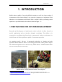
1. INTRODUCTION
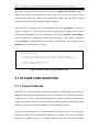
Mobile robots capable of traversing difficult terrain are useful in a large number of
circumstances where human labour is too expensive, dangerous or impractical. Such
industries or environments would benefit from a robotic vehicle performing certain
repetitive or specialized tasks such as those shown in Figure 1.1.
1.1 MOTIVATION FOR SYSTEM DEVELOPMENT
Research and development of multi-terrain robotic vehicles is often focused on
specific applications and are therefore designed accordingly. The ability to be
customized or reconfigured and function in an unstructured, outdoor environment is a
desired feature of robotic platforms capable of autonomous operation.
An emerging trend is the use of automated technology in farming and other
agriculture based industries. There is increasing potential for remote pasture analysis
and animal management to be carried out by mobile robots. Valuable human labour
can then be transferred to other tasks.
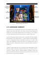
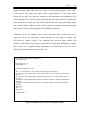
Figure 1.1 Robots used in dangerous environments LEFT: Volcano exploration1
RIGHT: Robot entering tunnel for nuclear waste disposal2
1
http://www.robovolc.dees.unict.it Robovolc is used to explore dangerous volcanic sites
http://www.bechtel.com/Briefs/0305/Yucca.htm Testing of robots for tunnel construction and
nuclear waste disposal
2
The Enhancement of a Multi-Terrain Mechatron for Autonomous Outdoor Applications
2
These devices have been restricted in the past due to technology limitations however,
as sophisticated devices become available, the requirements of co-ordination,
communication and precision control can be met by a robotic system.
Research and development of such a robotic system capable of replacing or
complimenting human labour has been initiated by the construction of a multi-terrain
mechatron (Cordes, 2002). This thesis uses the mechanical structure of this multiterrain mechatron, equips it with sensors, motor drivers, intelligence and other
electronics. High and low level software is developed and some mechanical
modifications are implemented so that at the conclusion of this project the mechatron
will have the capability to perform some autonomous tasks.
1.2 COMMERCIAL APPLICATIONS
The commercial applications for an autonomous mechatron capable of multi-terrain
operation are wide ranging and not only limited to farming applications. Other
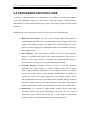
potential applications include the following:
•
Forestry – automatic tree grading and low level scrub clearing
•
Military – tactical reconnaissance and explosive disposal missions
•
Security – patrol of compound perimeter and intruder confrontation
•
Search and Rescue – disaster relief and urban survivor location
•
Terrain Mapping – digital profiling of open or underground terrain
•
Planetary Exploration – environment evaluation and facility construction
Taking into account these possible applications the mechatron must be capable of
carrying a large volume of application specific equipment. Therefore common robot
components such as motor drivers and sensors must be efficiently designed to allow
the addition of future components without overloading the mechatron.
Introduction
3
1.3 PROJECT SPECIFICATIONS
The objective of this project is to research and implement the necessary hardware and
software components required to eventually enable autonomous operation of a mobile
mechatron. The mechanical shell of a track-laying multi-terrain robotic vehicle has
previously been deigned and this project aims to equip it with the mechanisms for
operation and evaluate the performance of the installed components.
An autonomous mechatron is one which can independently monitor its operating
environment and make decisions that enable self control and execution of some
desired tasks. The robot will eventually be capable of accepting and analyzing
complex task descriptions for execution however, these high level functions are
outside the scope of this project.
This project involves a number of different aspects to achieve the objectives including
mechanical alterations, electronic circuit board design and software development in
different computer languages. These concepts will be brought together to enable
motion of the robot utilizing various sensors, electrical systems and control algorithms
to eventually achieve autonomous operation.
Future research by the Mechatronics Group into mobile robotic platforms may utilize
similar hardware and software elements to those used in this project, therefore an
emphasis is on the appropriate selection of these systems. By providing a detailed
review of commercially available sensors, motor driver units and computer
peripherals useful for robot control, future designers can reduce development time by
referring to this project.
This project considers the following attributes to produce a working mechatron:
•
Operating Environment – Operation of the mechatron is primarily
intended for outdoors where environmental conditions can greatly vary so
onboard systems should be chosen for durability and measures taken to
protect them from the elements.
4
The Enhancement of a Multi-Terrain Mechatron for Autonomous Outdoor Applications
•
Independent Operation – All power supply systems and computational
resources are to be mounted on the mechatron to facilitate self sufficient
operation.
•
Manoeuvrability – Design of motor control systems need to consider and
take advantage of the differential drive configuration to enable high
manoeuvrability over uneven terrain.
•
Software – Interface software to the hardware components and control
algorithms need to be designed to allow for future development and
extension.
•
Future Work – The design and implementation of each component must
consider upgrades and additions during future development.
1.4 PROJECT PLANNING
To attain the project specifications the following objectives must be met and roughly
adhere to the order of appearance:
¾ Examine initial mechanical platform and determine potential capabilities
¾ Determine and carry out mechanical modifications for operation and aesthetics
¾ Evaluate existing onboard electronics to establish operating conditions
¾ Select computer equipment for data processing and communications
¾ Identify and install a suitable power source and electronics supply
¾ Research and obtain sensors for robot localization and environment
interpretation
¾ Design and construction of interface electronics for sensors and other
peripherals
¾ Construct enclosure and mounting systems for sensors and electronics
¾ Development of hardware for motor control
¾ Installation of wiring and power distribution systems with overload protection
¾ Develop software interface to motors and sensors
Introduction
5
¾ Calibration and testing of sensors
¾ Provide communication link with remote base station
¾ Test and evaluate mechatron performance outdoors
The final result of this thesis will be a multi-terrain robotic platform capable of
autonomous operation outdoors. Supporting electronics and sensory systems will be
installed and evaluated to provide navigation data and obstacle avoidance. An
evaluation of available devices will facilitate future robotics research and a
comprehensive graphical software interface will provide access to robot control and
sensor data.
1.5 THESIS STRUCTURE
This thesis is divided into chapters and presented as follows:
Chapter 2
describes the background behind the project including the original
mechanical platform and the motivation behind the system
development.
Chapter 3
covers the theory and hardware associated with controlling the motors
using both existing and newly constructed driver modules.
Chapter 4
outlines the electronics and sensory systems that have been evaluated
and installed on the mechatron providing the means for future
autonomous operation.
Chapter 5
details the software algorithms written to control the robot including
hardware interfacing, sensor data acquisition and a user interface.
Chapter 6
presents the results of the various sensor evaluations and platform
testing completed. The entire thesis is then summarized and a brief
discussion on future work is outlined.
6
The Enhancement of a Multi-Terrain Mechatron for Autonomous Outdoor Applications
Background
7
2. BACKGROUND
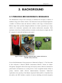
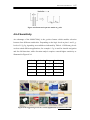
2.1 PREVIOUS MECHATRONICS RESEARCH
The Mechatronics Group at the University of Waikato has developed a number of
medium to large scale robotic vehicles. The robots have been specifically designed for
a number of different tasks and therefore exhibit a wide range of characteristics.
Robots range from specially designed platforms for indoor operation up to large
vehicles for underwater exploration and outdoor multi-terrain navigation. Each
mechatron in the fleet of mobile platforms contains an onboard power supply and full
PC computer for onboard intelligence and control.
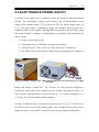
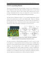
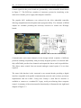
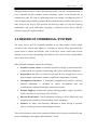
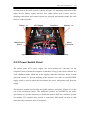
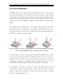
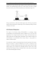
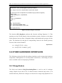
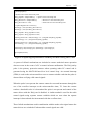
Figure 2.1 LEFT: Marvin, CENTRE: ROV, Outdoor Mechatron,
RIGHT: Itchy & Scratchy
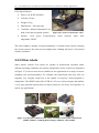
Four of the Mechatronics Group projects are illustrated in Figure 2.1. The first robot
in this collection is Marvin (Mobile Autonomous Robotic Vehicle for Indoor
Navigation). Equipped with various range and security sensors, Marvin is intended to
patrol indoor environments as a security device. Voice recognition and the ability to
portray
emotions
enable
effective
human-machine
interaction.
Underwater
exploration is the specialty of the Remote Operated Vehicle (ROV). Controlled from
the surface, the ROV includes a number of sensors including an inertial navigation
8
The Enhancement of a Multi-Terrain Mechatron for Autonomous Outdoor Applications
system and a wide field of view imaging system. A pair of identical robots (Itchy and
Scratchy) have been designed and built to investigate cooperative robotic interaction.
The project aims the curb the trend of mechanical scaling to perform ever increasing
tasks by utilizing multiple units working together in a controlled, outdoor
environment.
The mechanical construction of a track-based, multi-terrain vehicle has also been
carried out to investigate aspects of outdoor navigation. The outdoor robot directly
complements the existing fleet of vehicles thus enabling robotics research to span a
wide range of locomotion types and application environments. This platform will
enable navigation and control system development suited to the dynamic and often
difficult conditions found in an outdoor environment. The previous construction of
this platform forms the base of this project and is discussed further in section 2.3.
2.2 RESEARCH OF CURRENT SYSTEMS
A number of robotic platforms exist which are suitable for navigation of multi-terrain
environments. Research and development of such systems often focus on a very
specific task and as a result are highly design specific, lacking the ability for
reconfiguration. Other systems which are designed for research purposes, offering
configuration options, are sparse and very expensive, exceeding budgetary limitations
for this project.
Vehicles with a self-laying track locomotion system are usually designed for teleoperated tasks such as bomb disposal and traversing uneven terrain. In contrast,
wheeled robots that use non-differential steering such as an Ackerman configuration
are often useful for field operation and generally large, open spaces where speed is
considered more important than manoeuvrability. Existing in the department was a
self-laying, tracked mechatron capable of multi-terrain operation. To further explore
the functionality and operation of an outdoor robot, a decision to either modify the
current platform or investigate commercial systems was required. Some manufactured
designs which relate to this project were researched and evaluated based on system
configuration and onboard hardware pertaining to outdoor operation.
Background
9
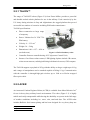
2.2.1 TALON™
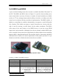
The range of TALON™ robots (Figure 2.2) from Foster-Miller3 provides a powerful
and durable tracked robotic platform for use in the military. Used extensively by the
U.S Army during missions in Iraq and Afghanistan, the rugged platform has proved
successful in a number of scenarios including EOD and reconnaissance.
TALON specifications:
•
Direct connection to large range
of weaponry
•
Power: Lithium Ion 36 VDC 750
Whr battery
•
Velocity: 0 – 2.32 ms-1
•
Weight: 34 – 54 kg
•
Dimensions: 0.86 × 0.57 × 0.28 m
(excludes arm)
Figure 2.2 TALON military robot
•
Controller: Remote controlled using OCU (Operator Control Unit)
•
Sensors: fixed focus colour camera, LED lighting Options include: IR camera,
colour zoom cameras, radiological/biological/chemical sensors, GPS compass.
The TALON supports a payload of 45 kg with the ability to drag a weight up to 91 kg
and a range of manipulators can be attached capable of lifting 11 kg. Communication
with the controller is through high-gain wireless up to 1200 m or Kevlar wrapped
fibre optics cable.
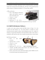
2.2.2 ACER
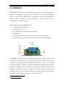
An Armoured Combat Engineer Robot (ACER) is available from Mesa Robotics Inc4
for use in heavy duty military based environments. The robot (Figure 2.3) is highly
mobile and easily transportable while having the durability to operate in the full range
of weather conditions including ice, snow, rain, sand and dust. The ACER robot
includes Ballistic Steel amour plating and has been designed for very heavy duty use
3
4
http://www.foster-miller.com
http://www.mesa-robotics.com
The Enhancement of a Multi-Terrain Mechatron for Autonomous Outdoor Applications
10
in a hazardous environment. Attachments such as earthmoving buckets and blades
enable terrain clearing and forced building entry. The large 1134 kg payload capacity
enables transport of equipment including an 11339 kg towing capability.
ACER specifications:
•
Power: Turbocharged 60 HP Diesel
engine with hydraulic system for
tracks and auxiliary tools
•
Velocity: 0 – 2.8 ms-1
•
Weight: 1905 kg
•
Dimensions: 2.1 × 1.58 × 1.42 m
•
Controller: Line of sight operation with portable briefcase type controller
Figure 2.3 ACER robot
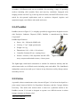
2.2.3 MATILDA Robotic Platform
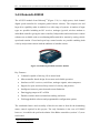
A smaller scale robotic platform called MATILDA shown in Figure 2.4 is also
available from Mesa Robotics Inc. The tracked platform is designed for remote
controlled missions primarily military related although provisions are available for
mounting of custom built manipulators and instrumentation. Robot control utilizes a
combination of RF and fibre-optics with a manually operated briefcase control station.
MATILDA specifications:
•
Power:
12
VDC
NiMH
(4- packs)
•
Operating Time: 4 – 6 hours
•
Velocity: 0 – 0.9 ms-1
•
Weight: 27.7 kg
•
Dimensions: 0.76 × 0.53× 0.3 m
•
Controller: 900 MHz portable control module with 2.4GHz video, joystick
Figure 2.4 MATILDA tracked robot
control of vehicle/camera/manipulator
•
Sensors: pan/tilt colour camera, IR thermal imaging, optional CBRN sensor kit
for chemical/biological and radiological detection
Background
11
A number of different track sets are available for traversing a range of operating
surfaces including slick (marble) floors and snow/icy conditions. Equipped with
imaging sensors and 220.5 kg or 441 kg tactical trailers, the MATILDA robot is best
suited for tele-operated applications such as explosives disposal, logistics and
equipment supply, surveillance and search and rescue.
2.2.4 PackBot
PackBot, shown in Figure 2.5, is a highly specialized, rugged robot designed to assist
with Explosive Ordnance Disposal (EOD). PackBot is manufactured by IRobot
Corporation5.
PackBot Specifications:
•
Power: 80 × 3000 mAh NiMH cells
•
Velocity: 3.7 ms-1 (high speed mode)
•
Weight: 18.1 kg
•
Dimensions: 0.41 × 0.88 × 0.18 m (base)
•
Controller: Pentium III core running Linux
•
Sensors: encoders, GPS, Superbrite and IR LED
Figure 2.5 Packbot
array, compass and attitude sensors, vision system
The lightweight, tread-based construction is suitable for numerous military and law
enforcement tasks over difficult terrain including stairs and rubble. The OmniReach
manipulator system can reach up to 2 meters in any direction to safely disrupt various
incendiary devices.
2.2.5 Urbie
A portable, urban reconnaissance robot, shown in Figure 2.6, has been developed in a
joint venture between NASA's Jet Propulsion Laboratory and the Carnegie Mellon
University. This small scale tracked robot is based on a platform similar to the
PackBot (section 2.2.4) and is designed to operate over difficult terrain in urban
hostage situations or disaster relief.
5
http://www.irobot.com
The Enhancement of a Multi-Terrain Mechatron for Autonomous Outdoor Applications
12
Urbie Specifications:
•
Power: 100 W NICAD Pack
•
Velocity: 0.8 ms-1
•
Weight: 22 kg
•
Dimensions: < 650 mm long
•
Controller: dedicated Pentium PC for
both vision and navigation systems
•
Figure 2.6 Urban reconnaissance robot
Sensors: 3-axis gyros, accelerometers, stereo cameras, sonar, laser
rangefinder, DGPS
The robot exhibits a number of useful capabilities of a multi-terrain vehicle, utilizing
the various sensors, the robot can accomplish stair climbing and stereo vision based
obstacle avoidance.
2.2.5 Other robots
Other robotic vehicles exist which are capable of multi-terrain operation under
different operating conditions and system configuration. Some of these are illustrated
in Figure 2.7, however most are not suitable for our application for a range of reasons
including cost and functionality. For example, the OmniTread robot (top left) can
negotiate very irregular terrain but is not capable of carrying a useful payload or
manipulator. The SPIKE robot (like ACER in 2.2.2) uses a diesel engine and exhibits
a very large payload capacity however these robots are too heavy and expensive to
run for our applications.
Figure 2.7 Collection of multi-terrain robots. Clockwise from top left: OmniTread,
SPIKE, URBOT, Lemming Robot, Ranger Modular robot, MARV
Background
13
2.3 EXISTING PLATFORM
Evaluation of commercially available platforms (section 2.2) reveals how unsuitable
they are for fulfilling the research purposes of this project. A low cost, medium scaled
track-based platform was required that could negotiate rough terrain and provide a
base for further research into outdoor robotics. The limiting factor with most of the
systems evaluated was the high cost and limited payload capacity. These factors
formed the motivation behind the design and construction of a custom unit.
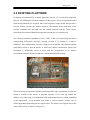
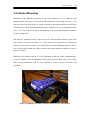
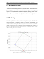
The existing mechanical platform (Cordes, 2002), is that of a track-laying mechatron
incorporating differential skid-style steering (section 2.3.2) similar to a tank or
bulldozer. This configuration provides a high level of stability and manoeuvrability
particularly suited to uneven terrain. A solid steel chassis construction ensures the
mechatron is sufficiently robust to cope with the irregularities of an outdoor
environment and provide the strength for a substantial payload capacity.
Figure 2.8 Existing robot platform at project onset
The track design incorporates dynamic tensioning and a bogie mechanism to allow the
tracks to contour to the terrain. A payload capacity of over 100 kg enables the
addition of a wide range of manipulators and instrumentation to be added depending
on the application. A top mounted steel frame is used to attach a robotic arm or
similar appendage depending on the required task. The robot in its original state at the
onset of this project is shown in Figure 2.8.
14
The Enhancement of a Multi-Terrain Mechatron for Autonomous Outdoor Applications
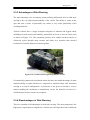
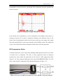
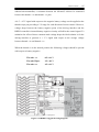
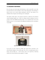
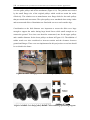
2.3.1 Drive Motors
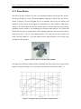
The drive system consists of a pair of permanent magnet, brush type DC motors.
Developed locally by a New Zealand company, Dynamic Controls Ltd, the motors,
shown in Figure 2.9 were designed for use in mobility devices for the elderly and
disabled. As the motors are designed for wheelchair use, they exhibit a high power
output of 230 W and thus are ideal for mobile robotic vehicles that need to powerfully
negotiate uneven surfaces. An attached gear reduction unit consists of a worm and
helical pair driving two pinion gears. The resulting reduction ratio between the motor
shaft and track is 394.33:1 and approximately 12:1 between the drive pulley and
track. The belt length is 2.3 m so the tracks travel a linear distance of 0.19 m for each
revolution of the gearbox.
Figure 2.9 Drive motors from Dynamic Mobility
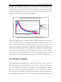
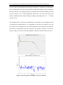
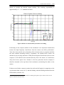
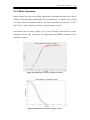
The typical performance characteristics including efficiency and power output of the
motors are shown in Figure 2.10, the motor specifications are listed in Table 2.1.
Figure 2.10 Typical motor performance characteristics
Background
15
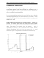
Some key points to note from the performance characteristics are the relationship
between efficiency and current. Although the rated current of 8 – 10 Amps produces
the highest efficiency of about 45%, actual operating current usually exceeds this
value meaning the motors are operating relatively inefficiently. This disadvantage is
however compensated by the large increase in output torque for a small decrease in
efficiency thus providing the power to the drive system required for rugged terrain
and slope negotiation. The maximum torque of 55 Nm is achieved at very low
efficiency and high currents, increasing the risk of motor burn out.
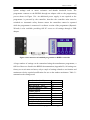
Motor Type
Permanent magnet commutator 24 V DC
Power Output (max)
230 W at 65 RPM
No Load Current
3.3 A (max)
Continuous Current
8.0 A
Torque Constant
1.1 Nm/A
Max Torque
55 Nm (50 A controller)
Parking Brake Type
Electro-mechanical 24 V DC
Parking Brake Holding Torque
> 50 Nm at output shaft
No load speed at output shaft
120 RPM nominal
Weight
5.5 kg each
Typical Backlash
1.5°
Motor Resistance
250 mΩ
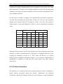
Table 2.1 Dynamic Controls WMT90112 motor specifications
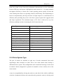
2.3.2 Drive System Type
The pair of motors are attached to rigid sets of tracks constructed from truck
supercharger belts mounted on either side of the robot chassis thus forming a
differential drive system. This configuration (also termed skid steering) is often used
in tracked vehicles designed for operation in unstable or loose surfaces due to the
extra traction.
A turn is accomplished by driving the tracks on each side of the vehicle at different
velocities. Symmetrical robots can rotate about the geometric centre by driving each
16
The Enhancement of a Multi-Terrain Mechatron for Autonomous Outdoor Applications
side at an equal but opposite velocity whereas straight line motion is achieved with
identical velocities in the same direction.
ℓR
ℓ
ℓL
θ
r
w
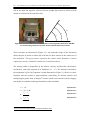
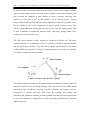
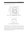
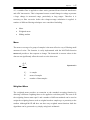
Figure 2.11 LEFT: Underside view of mechatron showing differential drive RIGHT:
Correlation diagram between track motion and mechatron movement
These concepts are illustrated in Figure 2.11. An underside image of the mechatron
shows the pair of tracks on either side with the two drive motors at the centre-rear of
the mechatron. The green arrows represent the relative track directions of travel
required to execute a clockwise rotation (as viewed from above).
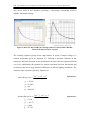
The turning radius is dependent on the relative velocity and therefore the distance
travelled by each track segment as in Equations 2.1 – 2.3. The distance travelled by
the mechatron is given by Equation 2.4 and illustrated in Figure 2.11 however, these
formulae must be treated as approximations, particularly for tracked vehicles and
turning angles greater than 10 degrees6 because small errors caused by track slippage
can rapidly accumulate rendering calculation results unreliable.
A L = rθ
Equation 2.1
A R = ( r + w)θ
Equation 2.2
AR −AL
w
A +AL
A= R
2
θ=
6
http://rossum.sourceforge.net/papers/DiffSteer/DiffSteer.html
Equation 2.3
Equation 2.4
Background
17
2.3.3 Advantages of Skid Steering
The main advantage of a locomotion system utilizing differential drive or skid-style
steering is the very high manoeuvrability of the vehicle. The ability to rotate on the
spot and turn a corner of practically any radius is very useful particularly when
avoiding obstacles.
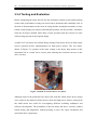
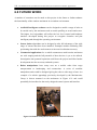
Tracked vehicles have a larger footprint compared to wheeled and legged robots
enabling increased traction and stability, particularly on loose or uneven terrain such
as shown in Figure 2.12. The continuous positive drive enables tracked vehicles to
effectively power through many terrains and climb over obstacles that wheeled
locomotors of similar diameters cannot negotiate.
Figure 2.12 Tracked vehicle negotiating difficult terrain
Geometrically symmetrical tread-based robots also have the added advantage of equal
manoeuvrability in either direction as compared to wheeled robots with Ackerman
steering or a tricycle configuration. A preference is not given to forward or reverse
motion enabling the mechatron to immediately reverse the direction of travel in a
confined space because a turn is not required.
2.3.4 Disadvantages of Skid Steering
There are a number of disadvantages to skid-style steering. The most prominent is the
high power requirements to implement a vehicle turn. Driving both tracks in different
18
The Enhancement of a Multi-Terrain Mechatron for Autonomous Outdoor Applications
directions and to a lesser extent different velocities is inherently inefficient and
demanding on the power supply.
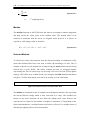
The worst case occurs when turning on the spot. As the vehicle rotates, the track
contact points move in an increasingly horizontal direction towards the track end
points as illustrated in Figure 2.13 (indicating a clockwise rotation). The high lateral
forces due to friction produce excessive wear on the tracks, particularly on rough
surfaces.
An indication of the frictional is shown in Figure 2.13. The magnitude of the friction
in proportional to the distance from the centre and therefore it follows that the total
force required depends on the total contact length and the weight of the vehicle. The
required forces can be reduced by designing a short, wide vehicle, using large turning
radii and placing most of the vehicle weight at the geometric centre.
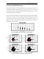
Figure 2.13 Skid steering turning on spot LEFT: Track segment movement direction
RIGHT: Relative friction forces between track and ground to overcome
Another important factor for autonomous robotic systems is the loss of odometry
information. Tracked differential drive vehicles inherently lose accuracy of position
information due to the non-uniform movement of the treads when turning. Any
slippage of the treads across the ground, even during relatively straight line motion
results in rapid accumulation of odometry errors which cannot be eliminated without
another method of positioning.
Background
19
2.3.5 Existing Onboard Hardware
This section describes the existing hardware components present on the mechatron at
the onset of this project. Although the mechatron could accomplish remote controlled
movement at the completion of the initial mechanical design, this was not the case at
the start of this project. The mechatron did not have any working electronic systems
due to many of the components being relocated to other projects. This formed the
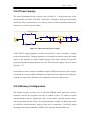
motivation to undertake a complete overhaul and redesign of all electronic systems.
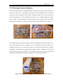
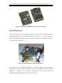
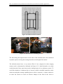
Figure 2.14 Original microcontroller board and PC motherboard
The original 8051 based microcontroller and PC motherboard is shown in Figure 2.14.
The microcontroller provides adequate space for modifications and connection to
peripherals however, the excessively large size of the board and plastic enclosure
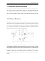
complicates mounting. The existing power supply system consisting of a UPS and
ATX converter are shown in Figure 2.15. Plastic boxes secure the ATX converter and
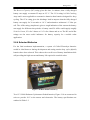
transformers making the entire power supply excessively bulky and heavy.
Figure 2.15 Original power supply consisting of UPS and ATX converter
20
The Enhancement of a Multi-Terrain Mechatron for Autonomous Outdoor Applications
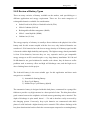
2.4 PROCESSOR ARCHITECTURE
A number of different hardware architectures are available to perform the onboard
processing algorithms required by this project. Data input/output, communications
and hardware control and monitoring are some of the tasks required of the central
controller.
Requirements of the architecture specific to this project are outlined below:
1) High Processor Speed: The CPU speed directly affects the number of
computational tasks that can be executed each second. A higher CPU clock
enables increasingly complex algorithms to be performed however at the
expense of increased power consumption which is not desirable for battery
based applications.
2) Data Memory: The data memory (RAM) is used for the temporary
storage of variables and data for the current application. Fast access to
memory with a large capacity is important for computationally intensive
processes such as image processing and floating point math.
3) Program Memory: Program memory is used to store the operation
instructions for robot control. To enable complex tasks such as motor
control and navigation algorithms a large program memory is required
because these tasks utilize a large number of instructions. In addition to
storing the actual robot-control application, the program memory stores
other applications such as the operating system and data analysis software
therefore a storage capacity exceeding gigabytes is desirable. The program
memory must also be easily reprogrammable allowing code modification.
4) Interfacing: It is expected a large number sensory devices and other
electronic systems will require interfacing to the main CPU. The selected
architecture must include provisions for a wide range of interfacing
protocols such as serial communications and data acquisition.
Background
21
Available systems were researched and evaluated on the basis of cost, size, processing
capability and system integration. Some of the solutions considered are discussed in
the following sections.
2.4.1 Embedded Controller
A wide range of embedded microcontrollers are available offering high processing
capability and low power consumption depending on the model. Data input/output
and many communication peripherals are often standard however functionality is
limited by program memory size mainly measured in kilobytes.
2.4.2 FPGA
FPGA (Field Programmable Gate Array) technology allows hardware based designed
to be implemented on a single IC. Although providing in-application reconfiguration,
FPGA’s are limited by gate number and development of external interfaces.
2.4.3 Handheld PC
Small computers such as a Palm PC offer reasonable processing power and very low
power consumption however connection to other hardware is difficult. Development
tools and driver support is not as widely available for handheld PC’s as standard
computers, increasing implementation complexity.
2.4.4 Laptop Computer
A laptop computer or notebook provides substantial processing power compared to
other small systems and low power consumption however the cost is high and
upgrades require entire system replacement. Data acquisition devices are often limited
to low cost USB systems with limited functionality.
The Enhancement of a Multi-Terrain Mechatron for Autonomous Outdoor Applications
22
2.4.5 Full Size PC
A full scale desktop PC provides the highest processing capability for a relatively low
cost however the size and power consumption limits the usefulness on a mobile robot.
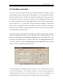
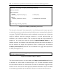
2.4.6 ShuttleX PC
A Shuttle PC provides a good compromise between a laptop computer and full size
desktop PC. Processing power is comparable to a standard PC while complex data I/O
can be achieved using the onboard PCI slot and USB ports.
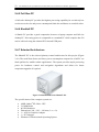
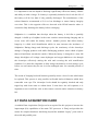
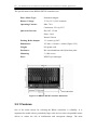
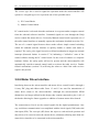
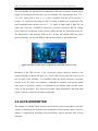
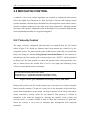
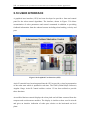
2.4.7 Selected Architecture
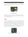
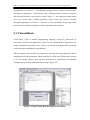
The ShuttleX PC is the selected primary control architecture for this project (Figure
2.16). The small form factor and lower power consumption compared to a full PC are
ideal qualities for mobile robotic applications. The system provides ample processing
power for hardware control and navigation algorithms and allows for future
component upgrades if required.
Figure 2.16 Small form factor ShuttleX PC
The specifications of the computer system are:
•
•
•
•
•
•
•
AMD Athlon® XP 2800+ CPU
512 MB RAM
80 GB Hard drive
Dimensions: 290 × 203 × 180 mm (l × w × h)
1 × AGP 8x Graphics Adapter
1 × PCI Adapter
Windows XP Professional Operating System
Background
23
2.5 ELECTRONICS POWER SUPPLY
A suitable power supply unit is required to power the numerous onboard electronic
systems. The Mechatronics group has previously used an uninterruptible power
supply (UPS), shown in Figure 2.17 to convert the 24 V DC battery supply to the 230
V AC. The high voltage is regulated to supply the computer and electronics by a
standard ATX PC power supply. Although this system worked and provided a cheap
and simple solution, a number of disadvantages were apparent and problematic for
mobile robots:
•
Heavy 19 kg weight of UPS
•
Large physical size of UPS takes up room on mechatron
•
Conversion of 24 V DC to 230 V AC then back to DC is inefficient
•
The UPS must be started by mains supply thus not appropriate for outdoor use
Figure 2.17 LEFT: Olympic OTC-1000A UPS RIGHT: ATX Switch mode power supply
ACE-828C
Rather than design a custom DC – DC converter for each electronic subsystem a
commercial switch mode power supply has been selected. Illustrated in Figure 2.17,
the ACE-828C Industrial Power converter accepts 18 – 32 V input and outputs 3.3 V,
±5 V and ±12 V for the computer and peripherals.
A study of efficiency (Payne, 2004) shows an increase of 30 % to 77 % efficiency of
the ATX converter over the UPS based system. This is important for a mobile robotic
application where conservation of energy is crucial to an acceptable running time.
24
The Enhancement of a Multi-Terrain Mechatron for Autonomous Outdoor Applications
2.6 BATTERY SELECTION
A number of different technologies are available to provide power to the motors and
other onboard electronic systems. Specialized devices such as fuel cells provide a
high power density to weight ratio but are restrictedly expensive. Cheaper and self
sufficient forms of energy such as solar panels provide endless energy but operation is
restricted to outdoors during daylight. In addition, a large installation would be
required to provide the high power required in this application. Due to the large size
and weight of the vehicle, batteries have been selected as the primary energy source.
Batteries are lower cost than the alternative systems researched and they can provide
the high capacity and high currents required by the motors and other electronics.
2.6.1 Required Specifications
A number of prerequisites have been considered when selecting a suitable battery
type. Physical dimensions of the robot platform inherently limit battery size and
weight however, these factors must be considered against operating time because
larger batteries generally mean a higher capacity. The battery technology itself is also
considered important because although some advanced options do exist such as high
capacity gel cells, the high price of these exceed the budget of this project and cannot
be used at this stage.
An analysis of the actual power consumption is discussed further in section 6.1
however a summary of the battery requirements are shown here:
•
Drive motors require 24 V DC
•
Electronics ATX converter require 18 – 32 V DC
•
Dimensions to fit chassis battery tray
•
Weight not to significantly reduce payload capacity
•
Approximately 20 – 25 Amps continuous current
•
Approximately 35 – 40 Amps peak current
•
Operation time exceeding 1.5 hours during development
Background
25
2.6.2 Review of Battery Types
There are many varieties of battery available on the market, each specializing to a
different application and energy requirement. There are five main categories of
rechargeable batteries available for consideration:
•
Sealed Lead Acid (SLA) or flooded lead acid (FLA)
•
Nickel-Cadmium (NiCad)
•
Rechargeable alkaline-manganese (RAM)
•
Nickel – metal hydride (NiMh)
•
Lithium-ion (Li-ion)
The energy capacity of a battery is usually a direct relation to the physical size of the
battery and for this reason coupled with the low cost, only lead-acid batteries are
considered. SLA batteries have the lowest energy density of all battery types but this
is factored with the high durability and capacity. The highest energy density attainable
is from Li-ion batteries, however they are very expensive and to get comparable
energy storage to an SLA would require a very large battery installation. Ni-Cad and
Ni-Mh batteries are good solutions for smaller scale robots, they do however suffer
problems such as memory effect and high self discharge rates, and the high cost is
also a limiting factor in this project.
The lead-acid battery is the most suitable type for this application and three main
categories are available:
1) Automobile Starting Battery
2) Deep Cycle Battery
3) Marine Deep Cycle Battery (hybrid)
The automotive battery is designed with thin lead plates, constructed in a sponge-like
fashion to provide very high currents in a short period of time. The thin plates allow
good contact between the sulphuric acid and current generating active material. The
depth of discharge is quite small, about 1 – 5% and is therefore easily recovered by
the charging system. Conversely, deep cycle batteries are constructed with thick
plates of solid lead and a higher density active material. This allows discharge with
less plate deterioration but does limit the current output compared to a starting battery
26
The Enhancement of a Multi-Terrain Mechatron for Autonomous Outdoor Applications
of similar size. The marine deep cycle battery, often called a “hybrid” is essentially a
combination of the previous two types. They can be used for engine starting in marine
environments but are also suited to deep cycling for powering onboard electronic
systems. Although cheaper than normal deep cycle batteries they cannot be
discharged as frequently without damage resulting. The cost of deep cycle batteries is
significantly higher than the automotive variety and a number of subcategories are
available.
Flooded or “wet” batteries are the most common and cheapest form of sealed lead,
deep cycle battery. These have a tendency to leak if tipped over or mounted in a nonhorizontal position but do allow consumed water (by H2 and O2 gas production) to be
topped up. Valve Regulated Batteries (VRLA) (also called SLA) maintain a positive
pressure of 3 – 5 psi within the battery causing internal recombination of the oxygen
and hydrogen gas. This allows the battery case to be sealed, preventing acid spillage
and emission of corrosive gas even in difficult installations. The VRLA groups
exhibit two different types of technology. The Gelled Electrolyte (Gel Cell) uses a
“jelly” like electrolyte so that no spillage is possible. AGM batteries use a glass fibre
material to retain the electrolyte and prevent movement.
The gel cells are generally better suited to cycling than the AGM but they are not as
robust and resilient as the flooded. Another technology combines the low maintenance
and sealed nature of the VRLA while retaining the resilience and integrity of the
flooded type. The RVP (Recombinant Vent Plugs) battery comprises a palladium
catalyst fitted to the vent plug where the hydrogen and oxygen is combined into water
before returning to the battery cell itself. This option was not explored because
batteries suitable for the mechatron could not be sourced locally in a reasonable time
frame.
2.6.3 Battery Ratings
A number of different battery rating methods are in use, some more suited to certain
types of battery. Standards set by SAE (Society of Automotive Engineers) have been
adopted by New Zealand battery manufacturers to standardize battery features.
Background
27
The Reserve Capacity (RC) rating gives the time, in minutes, that a fully charged
battery can supply a constant 25 amps at 25 °C. The CCA rating is Cold Cranking
Amps and is more applicable to automotive batteries than batteries designed for deep
cycling. The CCA rating gives the discharge load in amperes that the fully charged
battery can supply for 30 seconds at -18 °C and maintain a minimum 1.2 Volts per
cell. The A/Hrs rating (Amp/hours) gives a rough indication of the current the battery
can supply for different time periods. A battery rated 50 A/Hrs could supply roughly
50 A for 1 hour, 25 A for 2 hours or 12.5 A for 4 hours and so on. The RC and A/Hrs
ratings are the most useful indicators for battery capacity for a mobile robot
application.
2.6.4 Selected Batteries
For the final mechatron implementation, a system of Gelled Electrolyte batteries
would be ideal however during development and testing marine deep cycle (hybrid)
batteries have been selected. This reduces the overall cost of battery installation while
still providing the high current and battery life required in a mobile robot.
Figure 2.18 Hella Endurant battery
Two 12 V Hella Endurant Cyclemaster flooded batteries, Figure 2.18 are connected in
series to provide 24 V to the motors and electronics. The battery specifications are
outlined in Table 2.2
28
The Enhancement of a Multi-Terrain Mechatron for Autonomous Outdoor Applications
Manufacturer
Hella
Model
MDC24/85 Endurant Cyclemaster
CCA
515 Amps
Capacity
85 A/Hrs
Dimensions
270 × 170 × 250 mm (l×w×h)
Weight
19 kg each
Table 2.2 Selected battery specification
These batteries provide approximately 85 A/hrs / 25 A = 3.4 hours of operation time
when fully charged assuming a constant current of 25 A (refer section 6.1). To extend
the life of the batteries the running time should be reduced to ensure a 50% or less
discharge thus providing 1 – 1.5 hours of reliable operation and meeting the desired
criteria during development.
2.6.5 Charging Procedure
The batteries are individually charged using a pair of high current laboratory power
supplies. It is possible to charge both batteries in series using a single supply however
this is not recommended long term as it reduces the effectiveness of the charge and
could cause damage over time due to slight differences between the batteries.
Batteries designed for deepcyling require a slightly higher charging voltage than
standard automotive batteries. A charging voltage of 14.0 – 14.7 V (2.33 – 2.45 V per
cell) is applied across each battery ensuring the ground of the power supplies is
isolated. After periods of deep cycling where a significant portion of battery charge is
consumed a lower charging voltage is used for the early stages of charging. This
ensures the initially high charging currents do not damage the batteries. The charging
voltage should also be reduced once the charging process is complete to prevent
deterioration of the battery internals; this is called a “float” charge. A float charge
however can also cause corrosion of the positive plates so the ideal solution is to
remove the charge source completely and monitor the battery state, this can be
achieved using some high end chargers.
Background
29
It is important to note the depth of discharge significantly affects the battery lifetime
and ability to hold a charge. If a battery is repeatedly drained to low levels the life of
the battery will be less than if only partially discharged. The manufacturer of the
selected batteries recommends a 50 % or less discharge to ensure battery integrity
over time. This is the opposite effect as observed with NiCad batteries where is
essential to fully discharge the battery before recharging.
Sulphation is a condition that develops when the battery is left flat or partially
charged. A build up of sulphur in the water restricts current during charging and in
severe cases will render the battery useless. Another process that affects battery
longevity is called Acid Stratification which in turn increases the incidence of
Sulphation. During charge and discharge cycles the consistency of the electrolyte
changes. Charging produces acid while discharging produces water which is lighter
than acid and floats towards the surface. When the battery is charged to a near full
charge this higher cell voltage causes hydrogen and oxygen bubbles to rise through
the electrolyte effectively mixing the acid and reversing the acid stratification
condition. It is therefore important to fully charge the batteries at each charge cycle
before use and ensure they do not sit in an uncharged state for extended periods of
time.
The action of charging lead-acid batteries generally causes a loss of water which must
be replaced. This process is only possible in flooded lead acid batteries which have
removable vent caps. The electrolyte levels should be regularly checked and only
topped up with clean water to within about 13 mm above the cell separator; it is
important to not overfill the cells as this causes corrosion and a reduction in battery
life.
2.7 DATA ACQUISITION CARD
A suitable Data Acquisition (DAQ) card was required for this project to increase the
input/output (IO) capabilities of the main CPU processor. A DAQ card provides the
means for complex hardware interfacing beyond the standard “legacy” ports such as
the serial and parallel ports.
The Enhancement of a Multi-Terrain Mechatron for Autonomous Outdoor Applications
30
There exists a large number of data acquisition devices available, each best suited to
different operating environments and tasks. As a result, the cost and performance
characteristics can vary substantially between models. Primary tasks of the DAQ card
in this project include acquisition of sensor data, connection to and control of a motor
driver system and the ability to adapt to future project requirements.
A number of criteria based on the project requirements were used when evaluating the
different DAQ devices available, these include the following:
•
Interface to PCI slot or USB on ShuttleX motherboard
•
Include software drivers suitable for use in MATLAB
•
Fast acquisition of signals
•
Analogue input channels for sensor data acquisition
•
Analogue output channels for control and future systems
•
Digital IO channels for communications and control
•
Timers and counters for periodic signal generation and acquisition
A National Instruments M-Series multi-function DAQ (Data Acquisition) card
(Figure 2.19) has been selected to meet these specifications. Although a number of
low-cost, light weight USB devices exist, the performance and features of these are
generally very limited. The selected PCI-6229M model connects to the PCI slot and
offers increased performance with the added benefit of fitting within the computer
case so valuable mounting space on the mechatron is not wasted.
Figure 2.19 National Instruments PCI-6229M DAQ Card
Background
31
These devices are low cost and provide optimised functionality for a wide range of
applications in hardware control and sensor measurement.
Some key features of the card are:
•
NI-STC2 and NI-PGIA Technology
•
NI-DAQmx software drivers
•
32 16-bit Analogue Inputs 250 kS/s
•
4 16-bit Analogue Outputs 833 kS/s
•
48 TTL/CMOS Digital IO
•
32 DIO Hardware timed at 1 MHz
•
2 32-bit 80 MHz Timers/Counters
•
6 DMA Channels for fast data throughput
2.8 OTHER HARDWARE COMPONENTS
A number of other hardware components essential to this project have been selected
and some of these are outlined in the following sections. A complete review and
justification has been limited to a select number of important components however a
brief description of most devices is included in this section for completeness.
2.8.1 Wireless Network Adapters
A pair of wireless network adapters has been selected to provide a communication
channel between the mechatron and a remote base station. A laptop computer is
currently used as the base station however depending on the future implementation of
the device; a dedicated standalone base station may be utilized.
32
The Enhancement of a Multi-Terrain Mechatron for Autonomous Outdoor Applications
Figure 2.20 LEFT: DWL-120+ Wireless UBS Adapter RIGHT: DWL-650+ Wireless
Cardbus Adapter
A PCMCIA card bus adapter is used for the laptop while a USB adapter is installed on
the robot computer. Both devices are standard 2.4 GHz wireless adapters from DLink, shown in Figure 2.20 using the 802.11b protocol. The devices are connected
with an ad-hoc topology and transfer speeds are up to 11 Mbits/s with a strong signal.
The connection procedure using Remote Desktop software is described in section
5.2.1.
2.8.2 Onboard Video Camera
An onboard colour video camera, Figure 2.21, provides the user with a real time view
of the robot operating environment. This is used for robot monitoring or tele-operated
control during configuration and testing.
Figure 2.21 Logitech QuickCam Pro 4000 webcam
The camera connects to the host PC through a USB 2.0 interface. Video resolution of
640x480 is achievable in addition to a 1.3 mega pixel still camera. The operation and
connection to the webcam is described in section 5.6.4.
Background
33
2.8.3 Infrared Proximity Detectors
A number of Sharp GP2Y0A02YK infrared (IR) detectors illustrated in Figure 2.22
provide a measure of distance to objects surrounding the mechatron. Each device
produces an analogy DC voltage between 0.25 and 3 V giving a non-linear
representation of measured distance, updated every 32 ms. The process of converting
the voltage to a range measurement and the mounting of the sensors are described in
section 4.8.
Figure 2.22 Sharp GP2Y0A02YK infrared sensor
The sensors use a signal triangulation method instead of reflected intensity; this gives
greater immunity to signal variance for objects with different surface properties and
orientation. A range of approximately 20 – 160 cm is achievable under low lighting
conditions although this range is reduced in bright daylight due to sensor saturation.
2.8.4 Electronic Compass
An electronic compass (Honeywell HMR3300) shown in Figure 2.23 provides robot
heading information for the navigation and guidance system. The compass module
utilizes solid state magneto-resistive sensors to measure the Earth’s magnetic field.
The compass measures orientation in 3-axes giving measures of heading, pitch and
roll. Additionally, the heading is compensated for tilts of ±60° using the onboard 2axis accelerometer. Communication is through an ASCII based serial interface.
Compass modules are described in more detail in section 4.4.
34
The Enhancement of a Multi-Terrain Mechatron for Autonomous Outdoor Applications
Figure 2.23 Honeywell HMR3300 electronic compass module
2.8.5 GPS Receiver
Absolute positioning of the mechatron is achieved using a GPS (Global Positioning
System) antenna and receiver. The Motorola M12+ Oncore receiver, Figure 2.24, uses
the NAVSTAR satellite GPS system to accurately determine 3-dimensional position,
velocity and time worldwide.
Figure 2.24 Motorola M12+ Oncore GPS Receiver
The GPS receiver communicates through a serial data interface and positioning
information is reported once each second. The receiver includes a 12 channel design
meaning 12 satellites can be tracked simultaneously. The GPS system and
implementation is described in more detail in section 4.5.
Background
35
2.8.6 Inertial Sensor
A 3-axis accelerometer shown in Figure 2.25 provides the means for an inertial
navigation system to complement the GPS receiver. The MMA7260Q sensor from
Freescale Semiconductor is a low cost, capacitive micro machined device including
selection between four g sensitivities in the range ±1.5 g to ±6 g.
Figure 2.25 MMA7260Q 3-axis accelerometer
2.8.7 Motor Drivers
A pair of high power, reliable motor driver units (Figure 2.26) has been selected to
effectively control the mechatron drive motors. The Rhino DS72K scooter controllers
manufactured by Dynamic Controls provide a number of advantages over other
systems researched including programmable drive characteristics and that they have
been designed for the drive motors being used. Motor drivers and the implemented
motor control hardware are discussed in more detail in Chapter 3.
Figure 2.26 Rhino DS72K motor driver module
36
The Enhancement of a Multi-Terrain Mechatron for Autonomous Outdoor Applications
Motor Control
37
3. MOTOR CONTROL
3.1 INTRODUCTION
The process of effective and reliable motor control forms the base of this chapter. A
number of factors provide the motivation to create a single motor driver solution for
robot control. As technology advances, changes in platform topology and component
availability create problems when hardware peripherals such as DAQ cards and PC's
become obsolete and are upgraded. A motor driver should be relatively immune to
such events, still having the capacity to function and interface to future systems.
Another crucial feature is a generic or modular design topology. Other robotic
platforms could utilize the same motor drivers reducing robot design time and
troubleshooting complexity.
As stated in section 2.3.1, the drive motors are of DC variety, therefore the motor
drivers must be capable of transferring the high current 24 V supply from the batteries
through to the motors. A number of methods are available to achieve this and are
discussed in the following sections with an analysis of the various advantages and
disadvantages of each.
3.1.1 DC Motor Theory
A number of different motor types exist which are suited to different applications.
Since this project utilizes DC motors, a discussion on the principles of operation is
limited to this type. Although a few varieties are available, the DC motor essentially
consists of three main components. The rotor is the inner moving part that forms the
motor shaft where a load can be attached. Surrounding the central shaft is the stator,
this part remains stationary and usually consists of two or more permanent magnetic
pole pieces. A continuous copper wire called the armature winding is wound around
the rotor and produces a magnetic field when a current flows through it.
38
The Enhancement of a Multi-Terrain Mechatron for Autonomous Outdoor Applications
A mechanical commutator is connected to the rotor and winding assembly which
reverses the current polarity as the shaft rotates, thus generating a changing magnetic
field around the windings. The interaction between the changing magnetic dipoles of
the rotor and the constant stator magnets produce a torque and force the rotor to
continuously spin.
3.1.2 Possible Solutions
Two broad categories of motor control are possible, analogue and digital. Analogue
motor controllers, while relatively cheap and easy to implement for small manually
operated drive systems can be very troublesome for computer controlled applications.
A common technique is to convert the digital control signal to an analogue voltage
which then controls the motor voltage with a device such as a variable resistor. This
method is very inefficient and would dissipate excess power as heat, producing
significant stresses on the components. The complexity arises when a mechanical
actuator is required to adjust the variable resistor thus further impeding accurate
motor response.
Digital solutions that utilize relays are a good option when the frequency of switching
is small and no form of velocity control is required. A mechanical relay will only
allow simple on/off operation as a computer controlled mechanical switch. Direction
control can be achieved by adding a second relay for polarity reversal; however the
functionality is still too limited for this project and is not used. The high currents
present in the motors would easily burn out most readily available relays, therefore
expensive industrial grade devices would be required increasing project cost. Relays
also have a limited lifetime due to contact wear so are not suitable for the frequent
operation in a robotic vehicle.
A superior solution is to form a switching arrangement utilizing semiconductor
switches and a digital controller such as an embedded processor. The controller has
the facility to pulse the high power switches with a pulse width modulated (PWM)
square wave, (Figure 3.1) which in turn determines the power delivered to the motors
from the supply by the different levels of duty cycle.
Motor Control
39
(a)
(b)
(c)
Figure 3.1 PWM signals and transmitted power (a) 50% (b) 90% (c) 10%
The integration of a digital controller in the motor driver has the added advantage of
separating the timing critical motion control algorithms (PWM generation) from the
higher level robot software. This is particularly important when a non-real-time
operating system such as Microsoft Windows XP is used where process timing cannot
be guaranteed constant.
PWM signals cannot directly control the motors therefore a power converter is
required and the most common form of switching motor driver is the H-Bridge
topology illustrated in Figure 3.2. Four switching devices are connected to provide
four quadrants of DC motor operation, driving and breaking in both the forward and
reverse directions.
Vcc
S1
S3
Motor
S2
S4
Figure 3.2 H-Bridge switching topography
The H-bridge works by directing the motor current in a certain path by manipulating
the four switches S1 – S4. Forward motion is achieved by turning on switches 1 and 4
with 2 and 3 off. Likewise, when 2 and 3 are on and 1 and 4 are off, the motor rotates
in the reverse direction. Braking can be achieved by opening the high side (S1 S3)
switches and closing the low, thus creating a feedback loop through the motor and
ground.
40
The Enhancement of a Multi-Terrain Mechatron for Autonomous Outdoor Applications
3.1.3 Differential Drive Motor Control
The implementation of a differential drive motor control system presents a different
set of challenges compared to conventional speed or position only designs where
control of only one motor is necessary. Two motors are used to individually drive
each side of the robot, Figure 3.3, so the motor driver must have at least two channels
and be capable of controlling both motors in tandem. The motor driver should also
have provision for different control modes in order to adapt to different driving
preferences or robot installations.
Left Motor
Right Motor
Figure 3.3 Differential drive configuration consists of two opposing motors
Independent speed commands are required to individually command each motor. This
type of operation is best suited to generic motor control applications where the final
drive configuration is unknown or changeable and is therefore compatible with other
robotic vehicles under development.
Combined speed and steering commands are used to control the motors in
combination. The forward/reverse velocity information is coupled with the left/right
steering information to propel and rotate the vehicle accordingly. This method
provides a cost effective and straightforward way of moving and steering differential
drive systems such as tank-style robots.
Motor Control
41
3.2 EXISTING MOTOR DRIVERS
Previous motor controller circuits designed within the Mechatronics Group have been
quite varied and focus on platform specific designs. The main parallel between most
robotic platforms is that they run from a 24 V battery system. This section discusses
some of the past attempts at motor control and their shortfalls with respect to this
project.
3.2.1 Outdoor Mechatron
The original motor driver design for the outdoor mechatron was custom built and
utilized both a DAQ card and microcontroller to supply control signals to the high
power circuitry. A simplified power drive circuit for the motors is illustrated in Figure
3.4. The logic control signal drives a Darlington pair which is optoisolated from the
high power circuit for protection of the microcontroller.
Figure 3.4 Simplified single switch and relay drive circuit
Relays were used to implement direction switching however it is desirable to replace
such mechanical components with semiconductors to reduce risk of failure. Another
major limitation of this design was the lack of protection circuitry. The high loads and
back emf created by the motors produced excessive strain on the components often
resulting in damage after short operating periods. Development of a new driver
interface requires switch protection and snubber circuitry to dissipate the transient
currents.
42
The Enhancement of a Multi-Terrain Mechatron for Autonomous Outdoor Applications
3.2.2 Co-operating Robots
The pair of co-operating robots (Itchy & Scratchy, section 2.1) use a different type of
drive configuration to that of the outdoor mechatron's original circuit. A tricycle based
design is used with one motor for drive and the other positioned at the rear for
steering. Consequently the drive circuits are designed for a pair of motors with a
lower power rating than the outdoor mechatron making them unsuitable.
The motor drivers, illustrated in Figure 3.5, use a parallel communication protocol
with the microcontroller that is specific to the installed LabPC+ DAQ card. Although
the DAQ card has been recently upgraded to the NI PCI-6025E, the requirement of
this communication mode is still present which restricts implementation to robots
with this type of DAQ card and thus restricting the use of newer devices.
Figure 3.5 Itchy and Scratchy motor drivers LEFT: H-bridge circuit RIGHT:
Simplified schematic showing H-bridge and snubber circuitry
The power circuit uses a PWM H-bridge switching 24 V and 15 A up to 31 kHz.
Logic signals are 5 V and temperature and current sensing circuitry is installed. These
motor driver circuits include protection measures to prevent damage to the MOSFETs
including 1) free wheeling diodes, 2) R-C snubber and 3) transient suppression
diodes. Although these have mostly worked successfully, a couple of incidents have
occurred where the driver circuitry has failed. Due to the larger loading of the outdoor
mechatron it was concluded these motor drivers could not be guaranteed to function
under the high current conditions and so a different system was required.
Motor Control
43
3.2.3 Marvin
Documentation of the original motor drivers is sparse however it is known they were
unreliable and later replaced by those originally implemented on the outdoor
mechatron (3.2.1). Other circuits were designed and tested but none were successful
in continuous operation. More recently Marvin (section 2.1) was fitted with the
drivers specified in 3.2.2, however problems with reliability and the dependence on
certain hardware means they are not suitable for future research on Marvin. This robot
also utilizes a differential drive so development of drivers for the outdoor mechatron
considered the additional design criteria ensuring driver compatibility.
3.2.4 Underwater ROV
Like other robots, the ROV (section 2.1) uses a combination of 8-bit micro and DAQ
card to provide control. The original system (King, 2002) used a PWM controlled half
bridge rectifier for each motor however, operational problems led to a redesign
(Jungwirth (et. al), 2004) which also added a bootstrap circuit to correctly drive the
MOSFETs.
The motors are universal 110 VAC AEG, and therefore require a different driving
circuit to those previously mentioned which falls outside the scope of this project.
3.3 GENERIC MOTOR DRIVERS
The first attempt at creating a set of universal motor drivers was completed by a
previous master's student (Jensen, 2004). The project aimed to reduce robot
development time and simplify troubleshooting by creating a generic system for use
on multiple robotic vehicles. Consisting of a low power microcontroller board and
high current H-bridge driver the project potentially represented a significant step
forward for the Mechatronics Group.
44
The Enhancement of a Multi-Terrain Mechatron for Autonomous Outdoor Applications
The set of generic motor drivers were initially designed for the control of robotic
vehicles within the Mechatronics Group at the University of Waikato however future
development could commercialize the circuitry. These units were intended to be
installed on the outdoor mechatron, with this project aiming to ensure correct
operation and a reliable method of control.
Evaluation and testing of the system however outlined significant shortcomings of the
drivers thus they are not suitable for implementation on the outdoor mechatron.
This section describes the project and hardware developed including additional
modifications to the original modules. Results of testing and the reasons for not
installing the units on the mechatron are also discussed.
3.3.1 Project Outline
The proposed motor driver solution consists of a pair of high power H-bridge driver
boards and a low voltage microcontroller board for control. The digital circuit
replaces the DAQ card functions found in some other projects and provides the PWM
signals to control the switches. The power circuit controls the 24 V source to the
motors while providing circuit monitoring feedback such as current and temperature.
Low level control of the power driver circuit was separated from the main PC CPU to
free up valuable resources for other program tasks such as navigation of the platform.
As the controller must be adaptable to future hardware and software requirements the
system was separated into the two main components based on function thus
simplifying design and construction.
The following design criteria were also considered during the project:
1) Control of more than one motor
2) Easy transition from old designs incorporating digital communications
3) Bi-directional communication with circuit monitoring
4) Utilize component protection circuitry
Motor Control
45
3.3.2 Hardware Components
The high power components of the motor drivers consist of a pair of H-bridge driver
boards (Figure 3.6). Each utilize a full bridge, MOSFET based design allowing speed
and direction control in the four quadrants (section 3.1.2) of operation. An additional
MOSFET switch enables control of the electro-mechanical brake systems present on
Marvin and the outdoor mechatron.
A HIP4081A MOSFET driver IC from Intersil Corporation provides the necessary
drive signals to control the switches while current sense resistors monitor power
dissipation. The overall circuit design is a slight modification of the layout suggested
by the Intersil datasheet with added logic to enable direction control.
24V
12V
D1
R1
MBRS1100T3
1
2
3
4
5
6
7
8
9
10
4R7
Q1
IRF540
C9
100pF
U2
BHB
BHI
DIS
VSS
BHO
BHS
BLO
BLS
BLI
ALI
AHI
VDD
VCC
HDEL
LDEL
AHB
ALS
ALO
AHS
AHO
HIP4081A
20
19
18
17
16
15
14
13
12
11
D3
STTA3006P
B
R2
4R7
Q2
IRF540
D4
STTA3006P
C10
100pF
C11
100pF
C12
100pF
R5
4R7
R6
4R7
Q3
IRF
Q4
IRF
D2
MBRS1100T3
Figure 3.6 LEFT: One of the H-bridge power circuit boards RIGHT: Simplified
schematic showing H-bridge and HIP4081A MOSFET driver circuitry
Adjustment of dead-time switching between high and low side MOSFETs (to ensure
shoot though does not occur) is realized with two 500 kΩ variable resistors, another
10 kΩ resistor is available to trim the midpoint of the current sense circuitry to enable
calibration and correct determination of current through the H-bridge.
Switch protection consists of a RCD (resistor-capacitor-diode) snubber circuit to
dissipate excess voltage transients during switching. Provisions to attach zener diodes
are available to achieve faster clamping however power dissipation is lower than the
RCD snubber.
46
The Enhancement of a Multi-Terrain Mechatron for Autonomous Outdoor Applications
Control signals for the power boards are generated by a microcontroller board shown
in Figure 3.7. The PCB has a number of connector systems for interfacing to the
motor driver boards, power supply and computer controller.
The popular 8051 architecture was selected for the 8-bit embedded controller
allowing straightforward development and reprogram ability. Five channels of PWM
outputs are available providing the necessary resources to control two H-bridge
boards.
Figure 3.7 LEFT: Microcontroller board RIGHT: Microcontroller functionality
Communication and control channels for the design include a number of different
protocols enabling compatibility with previously designed systems. An external ADC
chip (ADC0844) provides four channels and outputs the data to an 8-bit parallel bus.
This allows motor control from an external analogue control system if it was later
required.
The same 8-bit data bus is also connected to an external header providing a digital
interface compatible with parallel communication protocols such as those previously
implemented with the LabPC+ DAQ card. Finally a serial RS-232 interface is
available to connect to a standard PC legacy serial port allowing direct computer
control. A summary of the microcontroller functionality is illustrated in the right hand
diagram of Figure 3.7.
Motor Control
47
3.3.3 Software Interface
At the time the generic motor drivers were being developed, the majority of robot
programming was done using the MATLAB language. It was envisaged this software
package would become the standard development environment for future projects and
as a result the motor driver software was based around it. Although MATLAB is used
as a major development tool, the final implementation of the robotic control software
may be based on C++ or some other real time language including a Linux based
system. These would better utilize the hardware resources and reduce the latency
associated with a Windows based applications therefore new motor control system
development has to account for this.
Four main functions were created to communicate with the microcontroller using the
serial port through MATLAB and the underlying Java Language platform. The
functions conect_micro.m and disconnect_micro.m setup and initialized the serial
port objects and deleted them at program termination. The talk_micro.m function
acted as an interface to both the read_micro.m and write_micro.m functions for data
transfer of motor commands and status feedback.
Figure 3.8 Initial motor driver front end GUI
A GUI (Graphical User Interface), shown in Figure 3.8, was created as the front end
for the MATLAB drivers. The interface provided a useful tool when testing and
troubleshooting the drivers and microcontroller code however functionality was
limited and did not provide means for easy customization of driver parameters.
48
The Enhancement of a Multi-Terrain Mechatron for Autonomous Outdoor Applications
3.3.4 Testing and Evaluation
Before integrating the motor drivers into the mechatron control system and mounting
on the robot, performance testing was carried out to determine their suitability. Due to
the lack of documentation at the onset of testing and the incomplete assembly of some
boards, initial testing was unsuccessful and full operation was not possible. Assistance
from the developer enabled initial basic circuit operation and the removal of some
software bugs present in the original design.
A small 24 V test motor was utilized during testing of the motor drivers to help ensure
correct operation before implementation on high power motors. The test motor,
shown in Figure 3.9, operates at the same voltage as the heavy duty motors on the
mechatron but at a much lower current, thus reducing the electronic stresses on the
drive circuitry.
Figure 3.9 Small 24 V motor driver test motor
Although some of the problems later discovered with this initial motor driver design
were related to the induced electrical stress from the high power motors, testing with
the small motor was useful for investigating different switching techniques and
software development. The portability of the test motor and driver circuitry enabled
bench testing and diagnostics without needing to move the entire mechatron and
associated drive components.
Motor Control
49
A significant problem discovered with the drivers was the detection of excessive
switching noise on the power rails of the low power electronic subsystems. Graphs
comparing the clean 5 V rail and the effect of the noise signal when the motor drivers
are activated is shown in Figure 3.10.
Noise pickup through the oscilloscope leads was ruled out indicating the noise was
permeating through the system, possibly due to a grounding problem.
Figure 3.10 LEFT: Clean 5 V supply rail RIGHT: Noise on 5 V rail
A closer inspection of the noise signal (Figure 3.11) revealed it was the same
frequency as the PWM driver signal of 34.72 kHz. This presented a useful starting
point for determining a potential set of solutions aimed at removing the noise.
Figure 3.11 Noise from PWM at 34.72 kHz LEFT: Noise close up RIGHT: PWM signal
In addition to the unwanted noise superimposed on the power rails the motor drivers
also suffered severe reliability problems during testing. On numerous occasions a
50
The Enhancement of a Multi-Terrain Mechatron for Autonomous Outdoor Applications
failure of the high power circuitry caused destruction of components and on one
occasion a small fire on the PCB. Although the exact cause of the problem has not yet
been resolved it is understood a shoot-through event is most likely. This has occurred
due to a failure of either the MOSFET driver IC to correctly co-ordinate switching or
the MOSFETs themselves becoming overstressed during operation.
Irregularities were located in the microprocessor code between the two driver
channels, seemingly causing one unit to fail more often than the other. Modifications
to the switching algorithms and dead-time adjustments were therefore completed in an
effort to reduce component stress however the problem, persisted indicating other
issues.
3.3.5 Modifications
A number of modifications were made to the original motor driver design, both for
robot mounting and in an attempt to provide reliable and noise free operation. This
section describes these additions and the results obtained.
Mounting Enclosure
A modification not directly related to the reduction of noise signals was the creation
of a suitable enclosure for the driver units. Made of clear acrylic plastic the enclosures
are designed to provide protection of the circuitry from environmental effects while
allowing a stable mounting platform to the robot chassis.
Figure 3.12 Mounting enclosure and cooling fans for motor driver
Motor Control
51
Two enclosures are attached together as shown in Figure 3.12 separately housing the
high power boards from the microcontroller to reduce interference. Three cooling fans
and opposite air inlets have been fitted to provide airflow along the heat sinks to
dissipate excess heat from the MOSFETs and diodes.
PWM Frequency
The PWM frequency of the H-bridge drivers was changed in the microcontroller from
36 kHz down to 12 kHz. A lower PWM frequency results in a lower MOSFET
switching frequency and therefore a reduced current draw on the battery supply
should result in less switching noise.
Figure 3.13 Noise after PWM changed to 12 kHz LEFT: Low duty cycle RIGHT: High
duty cycle
Although this slightly reduced the noise, the problem was still present as indicated in
Figure 3.13 showing the noisy 5 V power rail. The graphs also illustrate the
significant increase in noise present as the duty cycle in increased. The graph on the
left shows noise reaching a maximum of 6.4 V (5 V power with noise = 2.8 V peakto-peak) for the lowest level of PWM available. When the duty cycle is increased
enough to allow the motor to turn, overcoming the static inertia, the noise increases to
a maximum of 8.0 V as shown on the right hand graph, potentially causing damage to
any connected circuitry.
52
The Enhancement of a Multi-Terrain Mechatron for Autonomous Outdoor Applications
Shielding
The effect of electromagnetic interference (EMI) from the drive motors was
investigated. A thick aluminium shielding plate was placed between the motors and
driver units to act as a ground plane and direct the noise away from the low power
circuits. The components were also physically separated by the largest distance
possible as noise intensity reduces according to the inverse square of distance.
Neither method produced any noticeable difference to the noise magnitude indicating
it was not radiating through space but rather conducting through the cables. Twisting
the motor cables was also tested to cancel any differential mode noise present
however again this did not completely remedy the underling problem.
Smoothing Capacitors
The fact the noise signal appears at the same frequency as the PWM switching
frequency indicates a problem with the power supply not sourcing sufficient current.
Sealed Lead Acid batteries cannot supply high currents at the required rate because
they are relatively high impedance so as frequency increases the battery resistance
dominates and restricts current flow.
A large variety of high capacity smoothing capacitors were added to the battery
supply rails to act as fast responding charge reservoirs. Low pass filters were also
added to the PWM lines to smooth out the high frequency components of the signal
edges however these methods did not completely remove the noise.
Ferrite Beads
Instead of analyzing the frequency of occurrence of the noise signals (~36 kHz) the
frequency of the actual noise pulse (~20 MHz) was inspected as shown in Figure 3.14.
Ferrite beads can be used to attenuate these high frequency signals and were
Motor Control
53
investigated to remove the noise, particularly from conduction along the ground wires
between circuits.
Figure 3.14 Inspection of single noise pulse (f ≈ 20MHz)
Ferrite beads can be modelled as a series combination of an inductor and resistor, as
frequency increases the resistive component dominates and dissipates noise in the
form of heat. By placing the beads in series between all low power supply rails, signal
lines and ground planes on the microcontroller and H-bridge boards, the conduction
of noise was reduced but still not eliminated sufficiently for normal operation.
RFI Suppression Choke
Common mode noise can be reduced by installing EMI suppression filters on all lines
on which noise is conducted. The noise is often suppressed with two inductors
connected in series within the signal lines in the form of a RFI suppression choke
(Figure 3.15). The connection diagram for the selected ROXBURGH EMI C215 15A
device from Farnell is illustrated in the right hand diagram of Figure 3.15.
Figure 3.15 LEFT: C215 RFI noise suppression choke RIGHT: Connection diagram
54
The Enhancement of a Multi-Terrain Mechatron for Autonomous Outdoor Applications
These devices were connected in a number of different locations such as between the
ATX power supply and batteries and between the driver boards and batteries. The
most success was achieved when the units were attached between the drive motors
and the motor driver boards as illustrated in Figure 3.16.
Figure 3.16 Reduced noise density and amplitude after RFI choke added
The density and amplitude of noise was greatly reduced compared to previous
methods (Figure 3.13) indicating attenuation of high frequency noise by the inductors
however a significant amount still remained. Future work would involve
experimentation with chokes of different inductance than the specified 1 mH of these
devices, possibly better targeting the noise components.
3.3.6 Summary
The preceding sections have presented an analysis and problem solving strategy to
implementing the previously developed motor driver circuits. Although a vast number
of modifications were made to the units in an effort to remove noise, each with
varying degrees of success, a single underlying cause could not be found. It can be
concluded that measures to protect circuits and enhance noise immunity should be
designed into the project from initial stages as it is much more difficult to
subsequently make modifications when a problem is realized.
Motor Control
55
Although further analysis of the initial microprocessor code and a continual pursuit of
noise reduction would eventually resolve reliability issues it was decided not to
continue this path. The cost of replacement parts was already exceeding the price of
some commercially available systems and development time would be better spent on
other areas of the project. The decision was therefore made to cease the ongoing
maintenance and repair and rather investigate commercial motor drivers and the
interface required to implement them.
3.4 REVIEW OF COMMERCIAL SYSTEMS
The motor drivers will be eventually installed on the other robotic vehicles under
research so the system must adhere to a number of criteria. Most importantly the
system must be robust and reliable; each of the large robots could cause serious
damage to itself or the surrounding environment if the robot became uncontrollable
due to motor driver failure.
Other desirable attributers include the following:
•
Portable to other robots: It should be possible to design a system around the
commercial device capable of controlling other robots with minor alterations.
•
Reasonable Cost: The cost of the devices must be low enough not to exceed
project budget requirements without a significant compromise on quality.
•
Uncomplicated Interface: A reasonably straightforward interface requiring
minimal adjustment is desirable to reduce development time and
complications resulting from highly customized systems.
•
Product Support: Commercial systems offering product support should be
easily accessible for servicing in case of failure.
•
Physical Restrictions: Certain limitations relating to driver dimensions and
weight must be considered for positioning on the mechatron.
•
Features: As many extra functions additional to motor driving as possible
such as circuitry protection and intelligent software.
This section discusses some of the commercial motor driver boards considered for this
project including the advantages and limitations of each.
The Enhancement of a Multi-Terrain Mechatron for Autonomous Outdoor Applications
56
3.4.1 MAXI Motor Driver Kit
A compact H-bridge motor driver kit shown in Figure 3.17 is available from the
MONDO-TRONICS website7. They provide digital control of the power converter
from a standard PC parallel port or serial port by adding the optional “Serial Motor
Interface”.
Some features are:
•
Two motors per module
•
10 – 40 V range of motor voltages
•
10 A (max) continuous current with heat sinks attached
•
Optoisolation between digital and analogue circuits
•
Variable speed control via PWM inputs
Figure 3.17 Assembled Mondotronics MAXI motor driver kit
The modules come in kit form meaning construction is required before they can
function. Additionally these modules are simply the H-bridge component of the
driver. A combined unit is preferred because suitable control hardware consisting of a
microcontroller would still need to be developed.
The outdoor mechatron uses high powered motors that generate large amounts of
electrical noise. The MAXI motor driver kits are too simplistic, lacking the necessary
high current capability or protection circuitry such as a snubber or transient
suppression device. They are therefore not suitable for this project.
7
http://www.robotbuilder.co.uk
Motor Control
57
3.4.2 MD03 and MD22
A pair of similar H-bridge motor driver boards is available from Robot Electronics8 in
the UK. The MD03 and MD22, shown in Figure 3.18 provide robust medium power
motor control with a vast array of features. A number of control methods are available
such as an I2C bus, analogue inputs and the ability to interface to a hobby style radio
control receiver thereby offering versatility in implementation. The MD22 module, in
addition to controlling two modules independently, incorporates a useful differential
drive function. This enables one input to control forward/reverse velocity while the
other is used for steering, a useful feature for the outdoor mechatron. The MD03
offers many of the same features as the MD22 however it can also accept PWM
inputs from a microcontroller. Although it has only one channel, multiple MD03 units
can be cascaded for any motor driver application providing a higher current capability
than the MD22. Although both boards offer desirable features, (particularly the MD22
differential drive feature), the current requirements of this project (at least 25 A per
channel) exceed those of both units and are therefore not suitable.
Figure 3.18 LEFT: MD03 RIGHT: MD22
Summary of MD03 and MD22 features:
Number of motors:
Voltage:
Max Current:
Price (ea).
Control Modes:
8
MD03
MD22
1
5 – 50 V
20 A
£45.00
I2C Bus (up to 8 MD03 units)
0 – 2.5 – 5 V Analogue input
0 – 5 V Analogue input (sep. dir.)
RC Receiver
PWM at 20 kHz
2
5 – 50 V
27 A (13.5 A per chan)
£40.00
I2C Bus (up to 8 MD22 units)
Dual 0 – 2.5–5 V Analogue input
Dual 0 – 5 V Analogue input
RC Receiver – individual control
RC Receiver - with steering
http://www.robot-electronics.co.uk
The Enhancement of a Multi-Terrain Mechatron for Autonomous Outdoor Applications
58
3.4.3 Tecel D200
A high power H-Bridge DC motor driver board, shown in Figure 3.19 is available
from Tecel Microcontrollers9. The D200 is capable of driving many different motors
of any voltage up to 55 V making it suitable for use on a number or robot platforms.
The board contains a single switching bridge meaning two units are required for this
project. Onboard protection diodes and provisions for snubber circuitry are
advantages not found on some other boards researched.
Figure 3.19 Tecel Microcontrollers D200 DC Motor Driver Board
D200 features:
•
Power semiconductors: 4 110A MOSFETs
•
Current: Max 15 A with heat sinks
•
Voltage: 5 V for digital circuits, 0 – 55 V for motor
•
Board size: 63.5 × 63.5 mm
•
Circuit Protection: Filter capacitors, VTS diodes, snubber circuit ready
•
Onboard DC-DC converter for MOSFET bias voltages
•
Digital truth table and PWM inputs
Although the literature claims a board maximum of 60 A, the deceptive wording is
actually indicating this is shared between the four MOSFETs. In other words the
board cannot supply 30 A in one direction for extended periods of time and the
continuous current rating is actually 15 A when heat sinks are installed. This means
the board does not meet the current needs of this project and the additional hardware
and software development needed for PWM generation is not desirable.
9
http://www.tecel.com
Motor Control
59
3.4.4 MDM5253
The MDM525310 DC motor driver module shown in Figure 3.20 is a three channel Hbridge power amplifying module capable of controlling 3 DC motors simultaneously.
Control is via logic level PWM inputs at a frequency up to 20 kHz, additionally the
module provides feedback on motor current and position sensors such as
potentiometers or rotary encoders.
Some specifications of the MDM5253 are:
•
3 independent motor channels
•
Output drive of 5 – 28 V
•
5.0 Amp inductive DC load current capability
•
PWM inputs
•
Automatic PWM over-current limiting and short-circuit protection
•
Analogue current feedback and connectors for position feedback signals
Figure 3.20 MDM5253 motor driver board
The MDM5232 module provides some useful features for DC motor control such as
position and current feedback however the small size of the module makes it useful
for only low power applications. Integrated motor control IC’s have been used instead
of the usual MOSFET H-bridge topology thus substantially reducing the current drive
capabilities. Although some circuit protection features are available, the board is not
designed to handle large inductive loads such as those present on the outdoor
mechatron. This unit is best suited to smaller scale robotics projects such as robotic
manipulators where multiple, small servo motors are required.
10
http://www.drrobot.com
The Enhancement of a Multi-Terrain Mechatron for Autonomous Outdoor Applications
60
3.4.5 RoboteQ AX2550
The AX2550 module from RoboteQ11 (Figure 3.21) is a high power, dual channel
digital speed controller for computer guided robotic vehicles. The compact size and
large drive capability make it suitable for a wide range of systems. A number of input
types are possible including an R/C receiver, analogue joystick, wireless modem or
embedded controller giving the unit versatility. Independent and mixed motor control
schemes are available such as coordinating differential drive motion by setting vehicle
speed and rotation. Closed and open loop control modes are possible enabling both
velocity and position control with the addition of suitable sensors.
Figure 3.21 RoboteQ AX2550 controller module
Key Features:
•
2 channels capable of driving 120 A motor loads
•
Microcontroller based design for accurate and reliable operation
•
Interfaces to R/C receivers, serial lines, analogue signals, microcomputers
•
Support for open and closed loop control of velocity and position
•
Intelligent electronic protection and current limitation
•
Data logging output to PC or PDA
•
Durable weather shock resistant heat sinking enclosure
•
Field upgradeable software and programmable configuration options
The combined features and versatility of this device make it ideal for the demanding
motor control required in this project. The only limitation is the cost of US$495
however, it would be the preferred solution if the Rhino controllers (section 3.5) were
not located.
11
http://www.roboteq.com
Motor Control
61
3.5 SELECTED MODULES
As discussed, a number of commercial motor controllers have been researched and
evaluated for installation on the outdoor mechatron. A common restriction amongst
many of the devices available is the limited current capability. Many devices are
available for small to medium power motor control applications and the few found for
high power were too expensive and specialized for this project.
Another problem encountered was the difficulty of finding a complete solution
integrating high power drive and computerized control. Many devices provide the
high current H-bridge topography however they lack a control module to supply the
real-time PWM signals. These systems would require additional control hardware to
be developed to control the switching of the H-bridge units. Although the main CPU
could perform these tasks through suitable hardware such as a DAQ card, a separate
controller is preferred to decrease the software demands on the main CPU leaving it
available for more complex, high level tasks.
The selected motor controllers for the outdoor mechatron are a pair of RHINO
DS72K devices from Dynamic Controls Ltd12. Designed for mobility scooter control,
each module can supply currents of 70 A and are designed for small to medium sized
scooters and wheelchairs. The controllers are therefore sufficiently powerful to drive
the mechatron even in the most demanding outdoor conditions.
The RHINO motor drivers provide reliable and smooth operation by utilizing an
onboard microcontroller for control and circuit management. The microcontroller
provides the feature benefits and safety attributes offered by a digital system while
retaining the smoothness of an analogue controller. The units utilize high current
output components to sustain a powerful drive with high load compensation. This
allows excellent speed stability over various driving terrains.
12
http://www.dynamicmobility.co.nz
62
The Enhancement of a Multi-Terrain Mechatron for Autonomous Outdoor Applications
The specifications of the RHINO DS72K controllers are:
Drive Motor Type:
Permanent magnet
Battery Voltage:
17.5 to 32 V (24 V nominal)
Operating Current:
Max: 70 A
Continuous: 25 A @ 25°C
Quiescent Current:
Key Off: 1.5 mA
Sleep: 2 mA
Neutral: 50 mA
Parking Brake Output:
1.3 A (max) @ 24 V
Dimensions:
155 mm × 100 mm × 44 mm (Figure 3.22)
Weight:
650 grams each
Enclosure:
Die-cast aluminium with Nylon base plate
Mounting:
3 × M4 screws
Price:
NZ$276 per unit appx.
Figure 3.22 RHINO DS72K controller dimensions
3.5.1 Features
One of the main reasons for selecting the Rhino controllers is reliability. It is
important for mobile robots, particularly large scale devices to have dependable motor
drivers to reduce the risk of malfunction and consequent damage. The most
Motor Control
63
advantageous characteristic of the RHINO controllers is that they have been designed
to control the same motors installed on the mechatron. This was the major
consideration in selecting these drivers as this meant they were inherently designed to
cope with the loads and stresses present. This could not be guaranteed with most other
commercially available systems.
Safety features include automatic motor protection algorithms. These calculate when
the units are pushed too hard and the controller needs to reduce speed, thus preventing
motor burn out. Battery management software monitors current consumption and uses
"battery saver" technology to prevent damage to the cells. The drivers are also capable
of power regeneration, charge is returned to the batteries during braking and slope
decent extending the run-time for each charge.
Other controller features include:
•
'S-curve' and 'S3-TEC' algorithms provide smooth driving on many surfaces
with well controlled acceleration and braking
•
Die-cast Aluminium enclosures provide a solid, weather proof mounting
platform and integrated heat sink for excess power dissipation
•
Soft stop algorithms ensure the vehicle comes to a smooth shutdown in the
event of error
•
Slope safety limits roll back on hills to safe values
•
Automatic shutdown enables sleep mode after long periods of inactivity to
conserve power
•
Diagnostic indicators provide useful feedback to the user regarding system
status (section 3.5.5)
•
Flexible throttle control options (wig-wag, engager or speed input) allow left
hand, right hand or single ended operation
•
Data logging for fault codes and operating time enable easy diagnostics
•
Fully programmable operating characteristics enable system specific
configuration (section 3.5.4)
64
The Enhancement of a Multi-Terrain Mechatron for Autonomous Outdoor Applications
3.5.2 Interfacing
The controllers have been designed to interface to a mobility scooter tiller head such
as the one shown in Figure 3.23. The resultant interfacing system for the mechatron
must therefore be compatible in order for the controllers to correctly function.
Figure 3.23 Example scooter tiller head from Dynamic Controls Ltd
The standard wiring diagram for the controllers is illustrated in Figure 3.24.
Connection of the high power components such as battery supply and motor use AMP
250 series 6 and 4-way plug housing, the logic connectors use an 8-way AMP Mini
Mate'N'Lok plug housing. Three each of battery +ve and battery –ve terminals are
available on the driver modules, two of which provide the battery power using
separate fused cable pairs while the other provides power to the tiller unit or
interfacing module. An electromagnetic brake system is connected to the motor driver
modules through the same connector as the drive motors.
The main interfacing considerations are the logic connections, particularly the throttle
controller. The control input is designed to connect to a potentiometer so the
challenge was to construct a computer controlled interface to replace the analogue
reference voltage and wiper configuration. The throttle –ve pin is internally connected
to battery negative through 500 Ω to prevent fault current and to allow the throttle
resistance to be checked. Throttle +ve is connected to +5 V internally to provide an
interface that is symmetrical around 2.5 V. The system requires (checked by the
Motor Control
65
onboard microcontroller) a resistance between 4.4 kΩ and 5.4 kΩ to be connected
between the throttle +ve and throttle –ve pins.
A 0.5 – 4.5 V signal with respect to the negative battery voltage can be applied to the
throttle wiper pin providing a 2 V range for each direction of motor control. However,
voltage drops between the battery negative point of the driving interface and the
RHINO controller's internal battery negative circuitry will affect the control signal. To
minimize the effect of these common mode voltage drops the ideal solution is for the
driving interface to generate a ± 2 V signal with respect to the average voltage
between throttle +ve and throttle –ve.
When the throttle is in the neutral position the following voltages should be present
with respect to battery negative:
Throttle –ve
0.5 ± 0.1 V
Throttle Wiper
2.5 ± 0.1 V
Throttle +ve
4.5 ± 0.1 V
Figure 3.24 RHINO suggested wiring diagram
66
The Enhancement of a Multi-Terrain Mechatron for Autonomous Outdoor Applications
3.5.3 Handheld Controller
To perform initial testing and functionality verification of the motor drivers a
manually operated hand held controller was developed. The device models the simple
interfacing requirements detailed in section 3.5.2, consisting of two 10 kΩ
potentiometers for velocity control. Switches for power control are connected to the
"Key switch" pin via an LED through to 24 V and 10 kΩ resistors are connected in
parallel with the pots to meet the 5 kΩ criteria as the exact devices were not available.
Each group of controls interfaces to one of the motor driver units providing
independent differential control of the drive motors. A green LED indicates when
power is activated and also acts as the status feedback to flash error codes if they are
present. Motor control is achieved by rotating the potentiometer knobs from the centre
point in the desired direction of rotation, clockwise for forwards drive and anticlockwise for reverse.
Status/Power LEDs
Power switches
Velocity control
Figure 3.25 Handheld motor driver controller
3.5.4 Programming
The onboard microcontroller allows custom programming of the drive characteristics
to improve performance and best suit the intended application. Two versions of the
handheld programmer are available giving different levels of access to the settings.
The “Dealer” version allows modification of simple drive parameters such as velocity
and acceleration while the “Manufacturer” version also allows customization of
Motor Control
67
system settings such as motor resistance and throttle threshold levels. The
programmer connects to the RHINO through an adapter cable to the programming
port as shown in Figure 3.26. An additional power supply is not required as the
programmer is powered by the controller, therefore the controller units must be
switched on. Automatic safety features ensure the controllers cannot be operated
while the programmer is connected. A software version of the programmer (Dynamic
Wizard) is also available providing full PC access to all settings through a USB
adapter.
Figure 3.26 Connection of handheld programmer to RHINO controller
A large number of settings can be customized using the manufacturer programmer, a
full list of these are listed in the RHINO documentation (Appendix B). All settings are
factory set to suit most end users, only a couple of settings related to acceleration and
maximum velocity required modification for use on the outdoor mechatron. Table 3.1
summarizes the settings used.
Acceleration (1 – 10):
Deceleration:
Max Speed (0 – 255):
Forward Speed (1 – 10):
Reverse Speed:
Reduce Speed:
Motor Resistance:
Sleep time:
Max Current:
Soft Start Period:
Park Brake Delay (1 – 30):
Pot Neutral:
4
7
255
10
10
5
60 mΩ
30 min
70 A
50 (800 ms)
6
128
Table 3.1 RHINO programmer settings
68
The Enhancement of a Multi-Terrain Mechatron for Autonomous Outdoor Applications
3.5.5 Status Codes
The RHINO controllers provide status and diagnostic information to assist the user in
correcting faults with the scooter system. A fault with the controller or motor control
system will cause the status LED to flash and a horn to sound (if later fitted). The
sequence of light flashes and horn bursts represent a particular fault, referred to as the
"flash code".
Depending on the severity of the error and its impact on equipment/user safety, the
controllers will either display the code as a warning only or display the code and
prevent all operation until repaired. Once the appropriate fault has been located and
remedied, the controllers require a reset (power cycling) before operation can resume.
An explanation and probable cause of each error flash code can be obtained by
plugging in the programming device (3.5.4) or referring to Table 3.2 below taken
from the RHINO user manual.
Flash Code/Fault
Impact on Robot
1 Battery needs recharging
Will drive
2 Battery voltage low
3 Battery voltage high
Drive inhibited
Drive inhibited
4 Current limit timeout
Drive inhibited
5 Brake Fault
Will Drive
Drive Inhibited
6 Out of neutral at power Drive Inhibited
up
7 Speed pot error
Drive Inhibited
8 Motor volts error
Drive Inhibited
9 Internal error
Drive Inhibited
10 Push to fast fault
Drive Inhibited
Description
Battery charge is running low,
recharge soon
Batteries are empty, recharge now
Batteries are overcharged, either
due to charger or excessive
travelling down slopes
Over current for too long, robot
may be stalled or motor damaged.
Turn off for a few minutes
Park brake switch on during drive
(not installed on robot)
Park brake wiring may be faulty
Throttle needs to be in neutral
position during power up
Throttle wiring/resistance faulty
Motor or motor wiring is faulty
Other errors. (Contact service)
Robot has been pushed faster than
programmed limit (Not applicable)
Table 3.2 RHINO fault code reference
Motor Control
69
3.5.6 Robot Mounting
Mounting of the RHINO controllers to the robot platform is via a stainless steel
mounting plate ensuring a strong and stable attachment. Measuring 330 mm × 230
mm, the plate was bent along the centre to produce an angled platform to which the
controllers are bolted. Recommendations by the manufacturer for an inclination angle
of 15 – 75° were followed to allow free draining of moisture and adequate ventilation
for the cooling holes.
The units are positioned side by side at the rear of the mechatron directly above the
drive motors as shown in Figure 3.27. This ensures the controllers are sufficiently
distant from electronic systems to prevent EMI noise from disrupting circuitry. This is
also achieved by keeping the cables between the motors, batteries and drive units as
short as possible.
Both units are marked with an 'L' or 'R' indicating which side of the mechatron they
are to be attached. The corresponding cables and connectors have easy access to the
units easing maintenance and are also labelled to ensure correct connection and
operation.
Figure 3.27 RHINO controllers mounted on plate at rear of mechatron
70
The Enhancement of a Multi-Terrain Mechatron for Autonomous Outdoor Applications
3.6 Initial Interface Design
The first design of the motor controller board, shown in Figure 3.28, was based on
supplying a controlled analogue voltage to the throttle wiper pin. Since a mechanical
potentiometer is not able to provide an analogue voltage using a digital controller, a
suitable DAC (Digital to Analogue Converter) was investigated. Although a number
of different methods were available including custom designed DAC IC's, an initial
system employing PWM (Pulse Width Modulation) was developed.
PWM is a useful technique for controlling analogue circuits and can be achieved by
using the digital outputs of a microprocessor. The analogue voltage is digitally
encoded through the use of high resolution counters to modulate a square wave at
varying duty cycles. The analogue signal is retrieved at the receiving end by using a
suitable low pass RC (resistor-capacitor) filter to remove the modulating high
frequency.
Figure 3.28 Motor driver interface board utilizing PWM based DAC
One of the main advantages of PWM is that the controlling signal remains digital
from the microcontroller to the system, increasing noise immunity and increasing the
length of the communication channel available. PWM generation is a common and
easily accessible feature on most microcontrollers thus providing a simple, low cost
implementation.
Motor Control
71
A simplified schematic of the PWM based interface board is shown in Figure 3.29.
The input PWM signals from the microcontroller pass through a logic gate buffer, two
stage low-pass filter network and op-amp based voltage follower before reaching the
controllers. Two control lines are used to control the power through the key switch
lines and solid-state relays (not shown). All signals from the microcontroller are optoisolated from the motor driver to prevent potential damage using a TLP620-4 four
element photo-coupler.
+5_1
7
+24_1 JP2
220R
P4_4
R9
220R
PWM1 R11
220R
PWM0 R13
220R
1
U8
16KeyCntrl1 R8
+5_1
14
1K
2
3
15GND1
+5_0
14KeyCntrl0 R10
4
5
13GND0
12
6
7
11GND1
10
8
9 GND0
1K
R12
1K
R14
2
R3
Res2
1K8
+5_1
R4
C11
Cap
0.1uF
Res2
1K8
3
1, 5, 8
C12
Cap
0.1uF
GND1
1
KS1
2
Th+1
3
ThW1
4
GND1
5
Inhibit1
6
Th-1
7
8
Left Motor
+5_1
+5_0
+5_0
+24_0 JP1
1K
1
TLP620-4
3
Y
B
7
GND
MC74HC00AN
VDD
7
R7
2
2
14
U5A
A
3
Y
B
7
GND
MC74HC00AN
VDD
U3
MC33201P
2
R1
Res2
1K8
R2
C9
Cap
0.1uF
Res2
1K8
6
3
1, 5, 8
C10
Cap
0.1uF
4
P4_5
U6A
A
4
1
U4
MC33201P
6
GND0
+5_0
1
KS0
2
Th+0
3
ThW0
4
GND0
5
Inhibit0
6
Th-0
7
8
Right Motor
Figure 3.29 Simplified schematic of PWM interface board
A number of problems were present with this first design preventing it from operating
correctly. The main issue was the analogue voltage reaching the throttle wiper was not
correctly referenced. It was important to precisely keep the voltage between the Th
+ve and Th –ve pins otherwise the controllers would detect a problem and flash an
error code indicating the throttle wiring was faulty.
This was a particularly difficult task because minor fluctuations in PWM levels and
circuit voltages easily caused the output to exceed threshold limits. This was further
complicated by the unstable low-pass network, causing unpredictable voltage
fluctuations. Modifications to the RC values helped improve the response however, it
was at the expense of a dead zone where the output voltage was discontinuous for a
changing PWM.
These problems could have been remedied by further tweaking of the filter
components and the implementation of voltage limiting circuitry at the output stage.
A different interfacing method was however, developed to enable higher precision
control of the motors.
The Enhancement of a Multi-Terrain Mechatron for Autonomous Outdoor Applications
72
3.7 Improved Motor Driver Interface
The improved design for the motor driver interface board more closely matched the
interfacing attributes of the tiller head units. The motor drivers are designed to accept
a 5 kΩ mechanical potentiometer across the throttle pins. Therefore, the most
effective method of controlling the wiper voltage with a computer was through a
digital potentiometer.
+24_1 JP1
U4
+5
16
9
1
2
JP2
SDI
12
CLK
14
CS
11
13
Debugging Pin
RS
+5
15
10
VDD
DGND
SDI
CLK
CS
SDO
RS
SHDN
A1
W1
B1
AGND1
A2
W2
B2
AGND2
A3
W3
B3
AGND3
A4
W4
B4
AGND4
23
22
24
21
1
KS1
2
Th+1
3
ThW1
4
GND1
5
Inhibit1
6
Th-1
7
8
Left Motor
3
4
2
1
+5
19
18 KeyCntrl0
20
17
+5
7
8 KeyCntrl1
6
5
+24_0 JP3
1
KS0
2
Th+0
3
ThW0
4
GND0
5
Inhibit0
6
Th-0
7
8
Right Motor
AD5203
Figure 3.30 Simplified schematic of digital pot interface to motor drivers
The AD5203 digital potentiometer from Analogue Devices is connected to the motor
driver modules as indicated by Figure 3.30. Four individually operated and isolated
digital pots are available with two connected to the throttle connections while the
other two are used in the key switch circuitry to provide power control. The digital pot
reference points are directly connected to Thr +ve and Thr –ve on the motor drivers
ensuring the wiper voltage can never become out of range as occurred with the PWM
interface. The digital pots are 10 kΩ devices therefore additional 10 kΩ resistors are
connected in parallel across the two reference points meeting the 5 kΩ criteria.
The key switch circuitry is shown in Figure 3.31. An analogue voltage from the
digital potentiometers is converted to a digital control signal by the triggered op-amp
circuit to operate DIP reed relays. The relays replace the mechanical switches
installed on the handheld controller or tiller head assembly and pass current through
the status/power LED to the RHINO controllers.
Motor Control
73
+5
+5
LED1
KeyCntrl13
1, 5, 8
1, 5, 8
K2
Relay-SPST
6
8
4
K1
Relay-SPST
6
U6
MC33201P
6
2
1
2
KeyCntrl03
Res2
10K
8
LED0
+5
2
U5
MC33201P
6
2
1
Res2
10K
R8
Res2
22K
7
R10
7
R9
+5
4
R7
Res2
22K
KS0
KS1
Figure 3.31 Schematic showing key switch control circuitry
The resolution is 64 positions providing a large number of individual power settings
adequate for the outdoor mechatron. A drop-in replacement is available (AD8403)
providing 256 positions if required by future applications; the only modification
required is minor adjustment of the microprocessor code (section 5.9).
Interface and control of the digital potentiometer is through a microprocessor SPI
(serial peripheral interface) bus. The microcontroller connector, Figure 3.32, provides
access to the four SPI control lines CLK, RS, SDI and CS in addition to the two optoisolated status feedback signals STAT0 and STAT1.
JP4
+5
10
9
8
7
6
5
4
3
2
1
P1_3
P1_2
P4_7
P4_6
P4_5
P4_4
STAT1
STAT0
CLK
RS
SDI
CS
PWM1
PWM0
+5
+5
R3 1K
STAT0
R4
STAT1
U3
2
+24_0
1 Status0
2 DS3
+24_1
1 Status1
LED0
1K
LED1
DS4
Header 10
TLP620-4
Figure 3.32 LEFT: microcontroller header RIGHT: optoisolated status signals
The completed hardware interface to the motor drivers is illustrated in Figure 3.33.
Important components such as the motor driver connectors, and microcontroller
interface are highlighted. The advantage of this microcontroller system in addition to
74
The Enhancement of a Multi-Terrain Mechatron for Autonomous Outdoor Applications
effectively controlling the outdoor mechatron is the straightforward portability to
other robotic vehicles. A plastic enclosure, shown in Figure 3.34, is designed to
protect the interface board and provide a strong mounting platform to the mechatron
chassis.
Microcontroller Connector
Status Leds
Digital Potentiometer
Power Leds
Motor Driver Connectors
Figure 3.33 Completed RHINO motor driver interface board
Figure 3.34 Mounting enclosure for motor driver interface
Motor Control
75
3.8 MICROCONTROLLER
Due to complications in timing when sending SPI control signals directly from the
DAQ card (using the operating system’s internal clock), an independent
microcontroller system was developed. The microcontroller board, Figure 3.35, is
connected to the motor driver interface board and provides control of the RHINO
modules independent of the computer system.
DAQ Card
Radio Receiver
Motor Driver
Power
Figure 3.35 Microcontroller board for motor control
The primary task for the microcontroller is the interpretation of analogue and digital
signals from the DAQ card in order to autonomously control the motors. The
microcontroller is also interfaced to a radio control receiver enabling manual
operation. The microcontroller provides automated mode switching between
automatic (PC) and manual (RC) with failsafe protection. In the event of invalid or
non-existent signals from the DAQ card or radio receiver, the motor controllers are
deactivated until valid control is resumed.
The Enhancement of a Multi-Terrain Mechatron for Autonomous Outdoor Applications
76
3.8.1 Selected Controller
An 8051 based Philips microcontroller (P87C552) was selected for its familiarity
within the Mechatronics Group and the range of on-chip peripherals suitable for this
application. Listed below are the features associated with the 552:
•
80C51 CPU core
•
8 kB OTP EPROM
•
256 bytes internal RAM
•
Two 16-bit timer/counters
•
8 channel 10-bit ADC
•
Dual 8-bit PWM channels
•
Five 8-bit IO ports
•
Two External Interrupts
•
Two hardware serial interfaces (I2C bus and full duplex UART)
•
Watchdog timer
An extensive development board was initially developed to allow future expansion
however was consequently redesigned. Efficient mounting on a mobile robot requires
a small, uncluttered design, particularly on Marvin where space is limited. Figure 3.36
compares the two designs, the radio-control interface is detached making it an
optional addition and the full range of IO headers are replaced by design specific
connectors to the DAQ card and motor drivers.
Figure 3.36 LEFT: First microcontroller board RIGHT: Improved design
Motor Control
77
3.8.2 Power Supply
The power distribution board (section 4.2.4) provides 12 V and ground rails to the
microcontroller from the ATX PSU. Connection is through a polarized 2-pin header
which also allows connection of a 9 V battery pack for manual operation (without PC
turned on) or in case of power failure.
EMI Suppression Devices
Tranzorb
S1
2
JP1
3
SW-SPDT
1
2
3
U1
D5
1
1
Diode
C8
Cap
0.1uF
C1
Cap Pol1
10uF
IN
+5
OUT
GND
MC7805CT
C2
Cap Pol1
47uF
GND
Header 3
D3
D4
Tranzorb
Tranzorb
R1
3
C9
Cap
0.1uF
Res2
220R
1
Tranzorb
DS1
LED1
2
D2
2
D1
Figure 3.37 Microcontroller power supply
A MC7805CT voltage regulator is used to convert the 12 V into a constant 5 V supply
to the microcontroller. Filtering capacitors are included on both the input and output
stages of the regulator to remove high frequency noise and a diode (D5) provides
protection against accidental polarity reversal. The full power supply circuit is shown
in Figure 3.37.
Four inductive ferrite beads are included to suppress EMI present in the power supply.
Connected in a series-parallel combination to reduce the noise on both rails, both pairs
of beads are targeted at a different noise frequency to increase effectiveness.
3.8.3 Memory Configuration
The internal memory consists of an 8 kB OTP EPROM which means the memory
locations reserved for programs can only be written to once. To enable in-system
reprogramming with new application code, a non-volatile external memory device
was incorporated into the design. The microcontroller is capable of addressing a total
of 64 kB of external memory however this can be extended to 128 kB by taking
advantage of the microcontroller's NPSEN (Not Program Strobe Enable) pin.
78
The Enhancement of a Multi-Terrain Mechatron for Autonomous Outdoor Applications
A low on NPSEN indicates the microcontroller is reading from program memory,
therefore this line can be used to select the upper 64 kB (program) memory bank
during operation. The lower 64 kB (data) memory bank can be accessed when PSEN
is high thus giving data memory default access. This feature is used during download
mode, using a boot loader program to write code to data memory (actually program
memory), effectively "tricking" the microcontroller into updating the program code.
This distinction between download mode and run mode is made with a toggle switch
and logic circuitry as shown in the full schematic in Appendix A.2.
3.8.4 Programming
To enable downloading of new programs to external memory a boot loader client is
programmed into the internal ROM of the microcontroller. The purpose is to receive
new program code from the serial port and store it into external data memory so that it
can be recalled as program memory during run mode.
The DOS copy command is used (via the send to command) on the PC to send the
program HEX file through a serial cable and MAX232 transceiver. The boot code
receives and manipulates it byte by byte for storage. A RUN/PROGRAM toggle
switch is set to PROGRAM mode and the reset button pressed before code download
can commence. Upon download completion the switch must be set to the RUN
position and reset pressed to enable execution of the new code. This process must be
repeated each time the program code is updated.
3.8.5 DAQ Card Interface
A suitable interface protocol was required between the DAQ card and microcontroller
to transmit motor driver commands such as desired velocity and direction. As the
velocity control algorithms (section 5.8) are implemented on the main PC (external to
the micro), velocity feedback was not required however, suitable communication of
motor driver status indicators was needed.
Motor Control
79
A summary of DAQ card to microcontroller connections is shown in Table 3.3. Two
DAQ card analogue 0 – 5 V output channels are used to transmit the velocity control
to the microcontroller ADC with 5 V representing maximum power and 0 V stopped.
Micro 10
Micro
Pin Header
Port
1
P5.0
2
Function
DAQ
DAQ
Port
Connector
Speed 0
AO.0
22
P5.1
Speed 1
AO.1
21
3
P5.2
Direction 0
P0.0
52
4
P5.3
Direction 1
P0.1
17
5
P4.0
Power
P0.2
49
6
P4.1
Control Type
P0.3
47
7
P4.2
Status 0
P0.4
19
8
P4.3
Status 1
P0.5
51
9
GND
Ground
AOGND + DGND
10
P3.2
Safety Pulse
P0.6
16
Table 3.3 Microcontroller to DAQ card connections
The digital IO lines on Port 0 of the DAQ card are used to transmit and receive the
other control signals. The digital motor direction command (1=forward, 0=reverse)
from the DAQ card are also received by the microcontroller onboard ADC. Although
digital ports could have been used, this allows for future control expansion and the
ability to control up to four motors. The four received analogue signals can be
decoded into speed and direction by measuring the deviation in each direction from
the 2.5 V midpoints.
A single power control line is used for both motor driver units to reduce the control
lines necessary. Logic high on this line is converted to an SPI command for the digital
potentiometer and turns on the key switch circuitry to activate the RHINO controllers.
Two digital lines are used for feedback information on the motor driver status. These
signals represent the same information transmitted by the large, green LED's on the
interface board, signalling power activation and flashing error codes if any.
80
The Enhancement of a Multi-Terrain Mechatron for Autonomous Outdoor Applications
The control type line is used to signal the operation mode the microcontroller will
operate in. A digital high or low represents one of two possible states:
1) PC Control Mode
2) Manual Control Mode
PC control mode is selected when the mechatron is to operate under computer control
from the onboard software interface. Command signals are sent through the DAQ
card to control the motor drivers. Conversely Manual control mode represents use of
the radio control interface to manually operate the mechatron (detailed in section 3.9).
The use of a control signal between these modes allows simple control switching
within the onboard software interface to quickly disable or enable each mode as
required. The safety pulse signal is used as a failsafe mechanism to trigger an external
interrupt (discussed further in section 5.7.4) indicating a "still-alive" state of the
control software during the PC control mode. In the event of software or computer
hardware failure, the safety pulse will not be present and the microcontroller will
automatically switch to manual control mode to activate the radio receiver. Further
failsafe mechanisms (section 5.9) will bring the robot to a halt if the radio receiver
signal is not present.
3.8.6 Motor Driver Interface
Interfacing between the microcontroller and motor driver control board is through a
10-way IDC plug and ribbon cable. Ports 1.3 and 1.2 are used for transmission of
motor driver status to the microcontroller. Although the microcontroller PWM
channels are no longer utilized in this design, they remain connected to pins 1 & 2 of
the header allowing for future upgrades or addition of custom motor driver boards.
The connections to Port 4 are the control signals for the digital potentiometer. One
way serial data communication is accomplished with the clock signal (CLK) and serial
data input (SDI). The reset pin (RS) forces the wiper to each mid-scale position and
chip select (CS) is used to select the current device, ultimately allowing more than one
motor driver interface to be connected to the microcontroller.
Motor Control
81
3.9 RADIO CONTROL
Due to the large scale and weight of the Mechatron, a radio control (RC) receiver has
been interfaced to the microcontroller to aid in robot transportation. The advantage is
that the robot can be moved without requiring the main PC and software to be
initialized, thus saving time and reducing power consumption.
The interface board, Figure 3.38 permits the operator to manoeuvre the mechatron
around including loading onto a vehicle for transport without requiring at least two
people to lift it. The handheld transmitter, Figure 3.39, is matched to the receiver with
identical crystals. It is a two channel AM (Amplitude Modulation) device operating at
26.995 MHz.
Figure 3.38 Radio Controller interface board
Figure 3.39 Radio control handheld transmitter
Logic gates are used to buffer the PWM radio signal before connection to the
microcontroller through a 10-way IDC plug. The receiver is normally powered by a
battery pack providing 4.8 – 6 VDC however this is not required by connecting
directly to the microcontroller board regulated 5 V supply.
82
The Enhancement of a Multi-Terrain Mechatron for Autonomous Outdoor Applications
Electronics and Sensors
83
4. ELECTRONICS AND
SENSORS
A number of electronic and sensory subsystems were developed to integrate with the
central computer and robot hardware. These systems provide interface and control to
the motor driver system, sensors and other peripheral devices required to achieve
robot motion. Each component has been individually designed using a generic
approach to interfacing. This modular design ensures straightforward troubleshooting
and facilitates future upgrades and additions.
4.1 CENTRAL COMPUTER
At the heart of the robot electronics and control is the central processing computer.
Chosen for its processing capability and small form factor, the ShuttleX PC (section
2.4) provides all the performance and upgradeability required in a mobile robotic
platform.
4.1.1 Installation
Installation of the computer system on the mechatron requires consideration of
component access and functionality. The recessed component tray at the front of the
robot allows two mounting configurations of the ShuttleX illustrated in Figure 4.1.
Although the initial idea took advantage of the recessed compartment to secure the PC
case and lower the overall height, installation of other electronic components was
difficult due to the limited space.
The revised design placed the computer above the compartment allowing space
underneath for a custom electronics enclosure (section 4.10). Parallel steel bars are
bolted to the mechatron frame to which the PC case can be attached ensuring it does
not move. During development, cable ties secure the case to the steel beams to allow
easy removal and access to the electronic components below. An extension to the
84
The Enhancement of a Multi-Terrain Mechatron for Autonomous Outdoor Applications
ATX power converter cables was required in order to mount the unit on top of the
batteries and away from the CPU.
Recessed Option
ATX Converter
Cable Ties
Steel Bars
CPU
Figure 4.1 Computer installation LEFT: Original idea RIGHT: Revised option
4.1.2 Hard Drive Support
Excessive vibration and shock experienced by the mechatron when operating
outdoors, particularly on uneven terrain, can damage the computer hard drive.
Although future robot implementations would utilize a solid-state solution (such as a
USB flash drive) for program and operating system storage, this was not possible
during this project due to cost and the limited storage space of current devices.
A temporary solution to protect the hard-drive from mechanical damage was
employed during development. The hard drive was removed from the original
aluminium frame and repositioned in the upper (CD drive) section in a custom cradle.
The cradle, made from rubber and foam padding is designed to absorb excessive
vibration from robot motion thus protecting the hard drive from shock.
Figure 4.2 LEFT: Protective hard drive cradle RIGHT: Repositioned in ShuttleX case
Electronics and Sensors
85
4.1.3 Communication Interfaces
The ShuttleX computer contains one legacy serial (RS232) port and four Universal
Serial Bus (USB) ports for connection to peripherals. The limited serial ports restrict
the number of serial devices that can be connected which is a disadvantage as many
devices such as sensors utilize this protocol.
Figure 4.3 USB to serial adapter
To allow connection to devices such as the compass and GPS modules, a modular
connectivity system using a USB to serial converter is used (Figure 4.3). These
devices allow standard RS-232 based designs to be connected to a PC through the
USB ports, thus allowing a large number of devices to be connected (through a USB
hub). The operating system sees the adapter as a standard COM port thus allowing
configuration of port options such as COM number and data format through the
control panel.
The onboard camera and wireless networking adapters are USB based to allow
simple, future-proof connection. A single PCI slot is used for connection of the DAQ
card and the AGP slot can be used to interface a graphics processing unit (GPU) for
future computational applications such as 3D mapping.
4.2 POWER SYSTEM
The power system consisting of the batteries (section 2.6) and switch mode converter
(section 2.5) provides energy to the motors and all electronic devices. A modular
power distribution system has been designed to effectively power all peripherals
ensuring compatibility with future additions and upgrades.
86
The Enhancement of a Multi-Terrain Mechatron for Autonomous Outdoor Applications
4.2.1 Fuse Box
A fuse box is installed between the battery terminals and electronic devices to ensure
cut-out protection in case of a short circuit fault or excessive current draw. The unit,
shown in Figure 4.4, is constructed of strong plastic and includes heavy duty contacts
for durability and high current applications
Figure 4.4 Fuse enclosure
Two separate circuits incorporating four 35 A fuses are used for the motor driver
circuitry as recommended by the installation manual. A single 10 A fuse is used for
the electronics supply connected to the switch mode converter leaving one fuse
location free for future system configuration. High current cables (blue) connect to the
positive battery terminal while 60 A rated cables (red) connect the fuse box to the
peripherals.
4.2.2 Wiring
The wiring system was designed to ensure simple and reliable connectivity between
components. Polarized connectors and colour coded wire looms help prevent incorrect
connections and possible damage to expensive components.
Cables are kept as short as possible and twisted where appropriate to prevent
problems with ground loops and unwanted conduction of noise signals. Cable ties and
heat shrink tubing are used in abundance to keep cables tidy and grouped.
Electronics and Sensors
87
A subsection of the cable system is shown in Figure 4.5 indicating connection of the
motor drivers, battery supply and fuse box. Other cables such as those used for
charging connections and control signals are grouped and attached under the steel
frame to reduce disorder.
Battery -ve
ATX Supply
Motor Driver
Power
Fuse Box
Battery +ve
Motor
Connector
Figure 4.5 Subsection of wiring showing motor driver connection
4.2.3 Power Switch Panel
The switch mode ATX power supply, like most modern PC converters do not
completely turn off when the computer is shutdown. They go into what is known as a
"soft" shutdown mode which due to the supply's imperfect efficiency draws a small
quiescent current. To prevent draining of the batteries over time, an external DPDT
toggle switch is used to physically disconnect the power and ground rails from the
supply.
This has been mounted on an easily accessible stainless steel plate, (Figure 4.6), at the
rear of the mechatron chassis. Two additional switches are available for the motor
driver units as it is often necessary to disable the motors while the electronic systems
are running. The switches also provide a convenient "kill-switch" location to shut
down the robot systems in case of emergency.
88
The Enhancement of a Multi-Terrain Mechatron for Autonomous Outdoor Applications
Figure 4.6 Power switch and charging panel
The three charging terminals are also located on the rear switch panel for accessibility
reasons. An external power supply or battery charging system can be connected to
charge the SLA batteries either individually or as a pair. It is not necessary to switch
off the motor drivers while charging.
4.2.4 Power Distribution Board
A power distribution board illustrated in Figure 4.7 is designed to provide a central
connection point for all electronic peripherals. Power is sourced from the ATX
converter through the PCB mounted MOLEX connector providing +5 V, +12 V and
two GND connections. Number coded for easy connection, the polarized connectors
allow for 10 devices to be simultaneously connected.
Figure 4.7 Power distribution board
Electronics and Sensors
89
4.3 SENSOR OPTIONS
In order for a mobile robot to operate autonomously it must be capable of detecting
and analyzing the surrounding environment. To do this the mechatron must have the
means to accurately gather environmental information and process it to enable
intelligent decisions to be made on its operating process.
Although the detection and interpretation of surrounding objects is a natural process
for humans and other animals, this is not as simply implemented on a robot. There
currently does not exist a truly elegant or universal solution to mimic (for example)
the human sense of sight in a robotic system. Humans seamlessly use sight to estimate
range, analyze surrounding environment, detect potential hazards, acquire colour
information and to recognize and clarify objects. Although much research is centred
on developing this unified capability for a robotic system, the current methods rely on
combining partial data from a range of sensing devices. Each sensor is designed to
detect or measure a different type of environmental feature and relay this information
to a computer controller for analysis.
4.3.1 Requirements
A number of sensors have been researched and evaluated for implementation on the
outdoor mechatron. Although the primary operating environment is outdoors and over
difficult terrain, the mechatron will also operate indoors during development. This is
to facilitate algorithm testing such as obstacle avoidance and map building using walls
and doorways as reference points and as a result the sensory systems must be selected
to suit both environments.
Other key considerations in developing the sensor systems include the following:
•
Obstacle detection
•
Robot localization
•
Attitude and orientation
•
Terrain evaluation
•
Course correction
The Enhancement of a Multi-Terrain Mechatron for Autonomous Outdoor Applications
90
•
Object classification
•
Ranging sensors
•
Robot status and monitoring
•
Application specific sensors
Some applications, such as localization require more than one type of sensor whereas
certain sensory devices are capable of providing information suitable for a number of
tasks. A short review of available sensor technology for integration into the robot
follows in the next subsections.
4.3.2 Positioning
Information on robot positioning is crucial to the effective implementation of a
navigation system. A robot cannot deduce its current location with respect to the
entire operating environment or some goal point without some form of positioning
sensors.
Positioning sensors can be grouped into two main categories based on the data
acquisition techniques used. Relative position measurements acquire data referenced
to a single point at the origin. All calculations are based on deviations from this point.
Conversely, absolute position measurements use a universal reference such as a
global co-ordinate system or a set of markers at known locations. This enables
multiple robots operating in the same environment to use a common localization
reference that does not require a common starting point.
An inherent problem with relative localization methods is the long term drift and
instability of the results. All measurements have an associated error and therefore
accumulate over time. Absolute positioning has the advantage of finite errors but do
require extra infrastructure and expense to enable operation unless it already exists.
Sensors for robot positioning include:
•
Heading: mechanical gyroscopes, fluxgate compass, Hall effect compass,
magneto-resistive compass, optical/ring-laser gyroscopes, shaft encoders
•
Inclination: accelerometers, reed-switches, mercury tilt switch
Electronics and Sensors
91
•
Locating Beacons: ground based RF transmitters, GPS
•
Odometry/Velocity: relative shaft encoders, absolute position sensors,
ultrasonic ground speed sensor
•
Inertial Navigation: accelerometers, gyroscopes
4.3.2 Ranging
Sensors used to measure distance are extremely useful on an autonomous mechatron.
Range information is crucial to the safe avoidance of obstacles or classification of
objects. Map building requires distance information to build up a picture of safe and
unsafe territory.
Long range detection can be accomplished with laser range finders or ultrasonic
transmitter/detector pairs. Infra red sensors are useful in mid to short range
applications, particularly obstacle detection whereas extremely short range devices
such as tactile or bump sensors are used as a last resort.
4.3.4 Other sensors
A wide range of other sensors can be integrated into the robotic system depending on
the desired application. Robot monitoring sensors are used to ensure systems are
operating efficiently and prevent malfunctions. Temperature sensors such as
thermistors can monitor electronic circuits for over-heating while acceleration sensors
can analyze the vibration signatures of moving parts such as motors indicating
possible failure. Other environmental factors that can be monitored with sensors
include chemical/gas detectors, pressure and humidity (hygrometers). Scene
examination and object classification can be accomplished with a variety of imaging
sensors such as cameras. Each of these can be installed on the outdoor mechatron but
some are not required at this stage of the project.
92
The Enhancement of a Multi-Terrain Mechatron for Autonomous Outdoor Applications
4.4 ELECTRONIC COMPASS
An electronic compass provides robot heading information for the navigation and
guidance system. Robot positioning by odometry alone rapidly accumulates errors
particularly in tracked vehicles due the slippage of the drive components. The
addition of a heading sensor to the control system can correct direction errors and
increase the accuracy of the robot positioning software.
Figure 4.8 Earth's magnetic field
The Earth's magnetic field is approximately 0.6 gauss in an open-air environment13
with the field lines directed from the magnetic South Pole to the magnetic North Pole.
The magnetic field vector is horizontal near the equator but becomes increasingly
vertical near the poles (inclination or dip angle), as shown by Figure 4.8. The field
lines form the basis for magnetic compassing as units can be designed to measure the
field strength in the plane (2-axis sensors) thus providing a measure of heading.
4.4.1 Previous Module
The electronic compass originally selected for this project (Cordes, 2002) was chosen
for its significantly lower price than most other units available at the time and as a
result functionality was limited. The Vector V2X, manufactured by PNI Corporation
is a 2-axis magnetometer that measures magnetic field in a single plane. Accuracy
when level is ±2° RMS however, this decreases rapidly when the unit is tilted.
13
http://www.magneticsensors.com/landnav.html
Electronics and Sensors
93
A PCB interface board was designed (Figure 4.9) and DAQ card based interfacing
software was written. The Vector2X produces serial binary coded decimal (BCD) or
binary output format through the output pin representing the heading in degrees.
However, communication problems with the device indicated it was faulty and could
not be used.
Figure 4.9 Initial Vector2X compass and interface board
The other major disadvantage with this module is the lack of accuracy when the unit
is tilted. Modules with a 2-axis sensing element must remain horizontal or orthogonal
to the Earth's gravitation component. This is not practical for a robotic vehicle
designed for operation on rough and uneven terrain therefore selection of a 3-axis
device or one which could be mechanically gimballed was required.
4.4.2 Review of Available Modules
A range of commercially available compassing solutions were evaluated for
implementation of the outdoor mechatron. Some of these are discussed in the
following sections outlining the benefits and shortfalls of each unit in relation to this
project.
KVH C100 Compass Engine
The C1200 Compass Engine from KVH Industries14, shown in Figure 4.10, is a
standalone sensor designed for industrial applications. The module utilizes a
detachable toroidal, fluxgate sensing element useful for remote mounting.
14
http://www.kvh.com
94
The Enhancement of a Multi-Terrain Mechatron for Autonomous Outdoor Applications
Specifications include ±0.5° RMS accuracy when level, 100 – 0.04 Hz programmable
response time and six analogue/digital interfacing methods including RS-232,
NMEA-0183 and linear voltage.
Figure 4.10 KVH C100
Although the C100 has impressive features such as durability, and microprocessor
controlled magnetic interference compensation, the high US$795 cost of the unit
makes it unsuitable for this project.
CMPS03
The CMPS03 compass module (Figure 4.11) is available from Robot Electronics in
the UK. At around NZ$66, the compass is very low cost and uses a pair of Philips
KMZ51 magnetic field sensors mounted at right angles. This configuration means the
module can only measure magnetic fields in a single plane and therefore the accuracy
is poor compared to other units at 3 – 4°. Although the module is low cost and easily
interfaced to a microcontroller through the I2C interface, this module lacks the
functionality for a mobile robot platform and is better suited to hobby use.
Figure 4.11 CMPS03 Low cost compass module
Electronics and Sensors
95
Handheld Units
A number of handheld compass modules such the MapStar in Figure 4.12 have been
considered for installation on the outdoor mechatron. These devices are designed for
outdoor use in surveying or construction and are therefore durable and highly
accurate. Utilizing a range of sensing elements and user interface methods, handheld
devices provide a ready to use solution however, difficulties with PC interfacing make
them unsuitable for this project. Additionally, the cost far exceeds the OEM sensing
modules due to the extra hardware for data display and configuration.
Figure 4.12 MapStar fully integrated handheld compass module
Honeywell HMR3000
A three axis electronic compass is available from Honeywell15 providing a 20 Hz
response time, 0.5° RMS accuracy and 0.1° resolution. The pitch and roll tilt ranges
are ±40° and calibration routines are available for hard iron compensation of nearby
ferrous objects.
Figure 4.13 HMR3000 compass module from Honeywell
15
http://www.magneticsensors.com
96
The Enhancement of a Multi-Terrain Mechatron for Autonomous Outdoor Applications
Response times up to 20 Hz are possible due to the solid state sensing devices
allowing a faster response compared to gimballed fluxgate sensors. The module,
shown in Figure 4.13, comes with a protective plastic housing however functions per
price (US$700) does not compare well to other devices investigated and is therefore
not selected.
True North Revolution
The Revolution from True North Technologies16 is a tilt compensated electronic
compass with a heading accuracy of 0.5° and a ± 40° pitch and roll operating range. A
key advantage of the Revolution, shown in Figure 4.14, is the quick connect external
serial interface. This allows connection of the included PDA for testing and
calibration during installation. A number of operating modes are available and the
combination of 3-axis magnetometer and 2-axis electrolytic tilt sensors provide a
20 Hz response time. The Revolution has good features suitable for a robotic platform
however, a completely solid state module was desired and the functionality-per-price
(US$500) did not compare well to other modules. The handheld PDA unit was
considered an unnecessary expense for a PC interfaced sensor system.
Figure 4.14 TrueNorth Revolution compass module
TruePoint Compass Module
The TruePoint compass module from Point Research Corporation (now available
from Honeywell) is shown in Figure 4.15. The unit is designed for high performance
16
http://www.tntc.com
Electronics and Sensors
97
military use with 1° RMS accuracy on each axis and a 50 Hz update rate. The unit is
supplied with a durable aluminium housing and comprehensive test software. Data
from three silicon magnetometers and three MEMS accelerometers are combined to
provide highly accurate heading, pitch and roll data. The World Magnetic Model is
also incorporated enabling the module to automatically provide global heading
referenced to north and detection of magnetic anomalies. Although the high
specifications and range of features make these modules the preferred solution, the
high US$795 cost of the unit exceeds the project budget and therefore cannot be used.
Figure 4.15 TruePoint compass module and protective housing
98
The Enhancement of a Multi-Terrain Mechatron for Autonomous Outdoor Applications
4.4.3 Selected Module
An HMR3300 electronic compass module from Honeywell was selected to satisfy the
compassing requirements of the multi-terrain mechatron and other outdoor robotic
vehicles under development by the Mechatronics Group. This unit, although costing
more than some commercial systems evaluated, provided the best features per price
available. The price of the HMR3300 compass module is NZ$729 or approximately
US$385.
The compass measures orientation in 3-axes giving heading, pitch and roll data as
illustrated in Figure 4.16. Additionally, the heading is compensated for tilts of ±60°
using the onboard 2-axis accelerometer. Both SPI and UART interfacing methods are
available to connect to a variety of systems.
Figure 4.16 LEFT: No pitch or roll, heading in y-direction CENTRE: Roll is x-axis angle
relative to ground RIGHT: Pitch is y-axis angle relative to ground
Solid state magneto-resistive sensors (Honeywell HMC1021 and HMC1022) are used
to convert the Earth's magnetic field into a differential output voltage. This is fed to a
multiplexed ADC converter and microcontroller system to apply offset corrections
and heading calculations. An additional pair of inputs received from a 2-axis
accelerometer is used to calculate pitch and roll angles and correct heading.
An advantage is the ability to compensate for hard iron distortions from nearby
ferrous objects using the onboard calibration routine. This must be done when the
module is fitted to the mechatron to ensure the robot's steel frame is included
otherwise erroneous data may occur.
Electronics and Sensors
99
The specifications of the module are listed below:
•
Heading Accuracy:
1 – 4° RMS depending on tilt
•
Resolution:
0.1°
•
Pitch and Roll Range:
± 60°
•
Pitch and Roll Accuracy:
0.4 – 1.2°
•
Magnetic Field Range:
± 2 gauss
•
Update Rate:
8 Hz
•
Interface:
UART or SPI
•
Dimensions:
25.4 × 36.8 × 11 mm
•
Weight:
7.5 grams
Consideration must be given when the mechatron is in close proximity to power lines
or steel structures as they can distort the magnetic field, however this problem may be
remedied by fusing data from other sensors.
The HMR3300 was purchased with the demonstration kit to facilitate module testing
and evaluation. The kit contains additional hardware and Windows software to form a
complete development kit for electronic compassing. Included is the HMR3300
compass module, RS-232 adaptor motherboard, serial port cable with attached power
supply, interface CD and operation manual. The software shows heading, pitch and
roll through graphical ActiveX displays and allows calibration and zeroing of tilt
angles.
4.4.4 Interface Design
The interfacing protocol selected is serial UART (as opposed to SPI) to allow
connection to the PC through a USB to RS-232 converter. A PCB interface board was
designed incorporating a MAX232 serial transceiver IC to convert the logic level
serial data to high voltage for transmission over the serial line.
The schematic, shown in Figure 4.17 includes an onboard MC7805CT based power
supply and indicator LED. A polarized connector supplies +12 V power from the
power distribution board.
100 The Enhancement of a Multi-Terrain Mechatron for Autonomous Outdoor Applications
MAX232 Transciever/Line Driver
C5
Cap Pol1
1uF
U2
6
15
VEE
GND
Serial Connector to USB Adaptor
+5
J1
1
6
2
7
3
8
4
9
5
11
10
8
13
7
14
R2IN
R1IN
R2OUT
R1OUT
T2OUT
T1OUT
T2IN
T1IN
+5
16
2
D Connector 9
C2C2+
C1C1+
VCC
VDD
1
R1
Res2
220R
+5
Power Indicator LED
Tx
3
1
IN
VCC
C3
C4
Cap Pol1
1uF
Cap Pol1
1uF
C7
Cap Pol1
10uF
2
C6
Cap
0.1uF
MC7805CT
TX/SDO
CS
CAL
+5V DC
GND
8
+V
HMR3300 Electronic Compass
6-15V DC
+5
OUT
GND
RX/SDI
GND
7
U3
VCC
SCK
6
VCC
2
DS1
LED1
2
5
5
4
3
1
C2
Cap Pol1
1uF
Rx
U1
4
10
11
+5
C1
Cap Pol1
1uF
1
9
12
MAX232ACPE
+5
Compass Module
C8
Cap Pol1
47uF
JP1
1
2
3
C9
Cap
0.1uF
Header 2
GND
Figure 4.17 Compass module interface schematic
4.4.5 Mounting Enclosure
The compass module, interface PCB and USB to serial converter is mounted inside a
blue plastic enclosure shown in Figure 2.18. The case protects the electronics from
moisture and shock damage while providing a convenient mounting platform to the
mechatron. Positioning on the robot is above the ShuttleX PC case (Y-axis facing
forwards) keeping the module as far as possible from the motors and other high
current wires to reduce magnetic interference impeding compass operation.
Compass Module
Interface PCB
USB/Serial Adapter
Figure 4.18 Compass module protective enclosure
Electronics and Sensors
101
4.5 GPS
Accurate positioning is crucial to the operation of an autonomous outdoor robot. The
mechatron must have knowledge of its position relative to the goal location or
positioning of known obstacles in order for it to carry out tasks. One form of sensor
available to achieve reliable, absolute positioning is the Global Positioning System
(GPS). GPS is a popular localization tool for navigation of mobile robots due to the
constellation of orbiting satellites providing world-wide coverage. Relative
positioning using odometry alone produces poor results accurate to only 5 – 10 m for
straight line motion. The errors accumulate due to track slippage and uneven terrain
requiring the implementation of an absolute positioning system such as GPS.
4.5.1 Background
GPS is an outdoor positioning system designed, financed and operated by the U.S.
Department of Defence (DoD). The system was developed to provide continuous,
worldwide 3D positioning to the full range of military platforms at sea, land and air.
Civilian use of GPS currently far exceeds military use despite the project origins
however, as it is still operated by the DoD they have the ability to restrict performance
at any time. Despite this limitation there is substantial innovation in civilian GPS
technology and applications some of which are aimed at overcoming some of the
current constraints applied by the operators.
GPS positioning works on the mathematical principle of 3-dimensional trilateration.
This method uses the distance between the receiver and satellites to create an
imaginary system of spheres around the satellites. The intersection points of the
spheres represent the receiver location therefore at least 3-sattelites are required for a
3D fix. The receiver determines the locations of the satellites and distance to them by
analyzing high frequency, low power radio signals sent by the satellites. A long
digital pattern called a pseudo-random code is transmitted by the satellite which is
compared to an identical signal generated by the receiver. The phase shift represents
the signal travel time and therefore the distance (by multiplying by the speed of light).
102 The Enhancement of a Multi-Terrain Mechatron for Autonomous Outdoor Applications
In order to make this measurement both the satellite and receiver require a precise
system of time keeping down to the nano-second. Atomic clocks using rubidium (and
later caesium) are installed in each satellite to achieve accuracy and long term
stability of a few parts in 1014 per day (about 1 sec in 3,000,00 years) . Costing
between US$50 000 and $100 000 each and weighing more than 20 kg, atomic clocks
are not suitable for the receiver equipment so quartz crystal clocks are used. They
offer excellent short term stability therefore the receiver uses the timing signals from
at least 4 satellites to update the onboard clock, effectively getting atomic clock
accuracy for a fraction of the cost.
The GPS system consists of three segments as illustrated is Figure 4.19. The space
segment consists of a constellation of 24 (27 including 3 backups) orbiting satellites
and the signals they broadcast. They orbit on six equally spaced planes at an altitude
of about 20200 km and period 11 hours 58 minutes guaranteeing at least four satellites
are visible at anytime from any location.
Space Segment
User Segment
Control Segment
Figure 4.19 Three GPS operation segments
The control segment consists of five ground stations, including the master control at
Schriever Air Force Base in Colorado Springs. These facilities provide satellite health
monitoring, data up-linking, telemetry, satellite command and control, and the
calculations of satellite orbit and clock offset. By tracking each satellite and
calculating the ephemeris (satellite position) updated clock and repositioning data can
be sent to the satellites to compensate for errors caused by gravitation forces and solar
radiation pressure.
Electronics and Sensors
103
4.5.2 Receiver
The GPS receiver selected for this project is the M12+ Oncore from Motorola. It is a
cost effective solution designed for automotive use and is therefore a physically small
unit with low power consumption. Initialization times are small with a Time To First
Fix (TTFF) of 15 – 60 s and an internal reacquisition time < 1s.
To enable the receiver to pick up signals from satellites, a suitable antenna must be
connected. The module, shown in Figure 4.20 includes a micro-strip antenna, ceramic
radio frequency (RF) filter and a signal preamplifier. The receiver and antenna pair is
designed to receive L1 band (one of the two GPS carrier waves where L2 is for
military use) signals at 1575.42 MHz. Modulated onto this signal at 1.023 MHz is the
C/A (Course Acquisition) code which is a Pseudo Random Noise (PRN) sequence
defined for each satellite. Tracking of 12 satellites simultaneously is possible as the
receiver architecture consists of 12 channels. This allows selection and rejection of
data from satellites with poor data or technical problems.
A range of features are available on the M12+ including data filtering and the
input/output of almanac and ephemeris data. In addition to longitude and latitude, the
M12+ also provides output data on 2D and 3D velocity, altitude, heading, time, and
satellite status and signal quality. The module can also be configured for differential
GPS which improves the positioning capabilities by using a base station to transmit
correction data. The additional cost of the infrastructure and limited operating area
however restricts the use of differential GPS for this project.
Figure 4.20 LEFT: GPS antenna and receiver RIGHT: Interface board
104 The Enhancement of a Multi-Terrain Mechatron for Autonomous Outdoor Applications
The GPS module was purchased as a standalone OEM unit meaning a suitable power
supply and communication interface was not included. The requirements are a 2.75 –
3.2 V DC supply and as only a 3.3 V rail is available from the ATX converter, a
custom 3 V circuit incorporating an LM317 voltage regulator was constructed. The
serial communication interface uses a 0 – 3V signal at 9600 baud, 8 data bits, no
parity and 1 stop bit. A MAX232 transceiver is used to convert to RS-232 voltage
levels which are fed directly to the serial to USB converter for connection to the PC.
The dimensions of the interface PCB are 60 × 40 mm and include LED's for power
(green) and pulse–per-second (PPS) to indicate the module is operational (red).
Figure 4.21 LEFT: GPS receiver and interface board in protective case
Mounting of the GPS receiver is by a protective plastic enclosure similar to the
compass module as shown in Figure 4.21. As the GPS receiver does not need to be in
line of sight of the satellites, it is installed inside the metal electronics enclosure
(section 4.10) for safety and aesthetics. Although the antenna will operate within
some types of protective casing, it is positioned at the highest point possible at the
centre of the mechatron. This decreases possible signal degradation and multi-path
effects caused by reflections off other components.
4.6 ACCELEROMETER
The addition of a MMA7260Q inertial sensor from Freescale Semiconductor provides
a means of measuring acceleration of the mechatron. Accelerometers can be used in a
number of applications including robot positioning, impact detection and velocity
detection.
Electronics and Sensors
105
4.6.1 Advantages
Certain operating environments can cause restriction or loss of the GPS signal such as
canyons, large buildings or foliage such as under trees. The accelerometer can be used
in sensor fusion applications as a backup or complement to standard GPS. Robot
acceleration, and thus displacement by double integration, is measured to provide a
reliable and accurate representation of robot position over the short term, thus
allowing continued navigation without the GPS.
Additionally, the accelerometer can be used to "smooth-out" the noisy GPS data using
Kalman filtering. Deficiencies in the GPS system (discussed in section 6.4.5) cause
large position jumps even for stationary operation, these can be reduced by taking
advantage of the complementary error attributes of the accelerometer and GPS listed
below.
1) Accelerometer error is relative and increases without bounds
2) GPS error is absolute so is always limited to a certain degree
The fast response time and short term accuracy of the accelerometer can fill-in the
gaps between GPS data and detect anomalies. If a large position change is reported by
the GPS in a short time, (due to an error), the accelerometer data are used to confirm
this or discount the data as physically impossible, thus improving localization
accuracy.
4.6.2 Device Specifications
The MMA7260Q is a low cost, capacitive micro machined accelerometer (MMA)
which features on board signal conditioning and temperature compensation. The small
6 × 6 × 1.45 mm 16-lead QFN package and low power consumption make it ideal for
battery applications and integration on a mobile robot.
Also included within the module are switched capacitor based 1-pole low pass filters,
this means external passive components are not required to set the cut-off frequency.
106 The Enhancement of a Multi-Terrain Mechatron for Autonomous Outdoor Applications
Other features and specifications of the module include:
•
Selectable g-levels (1.5g/2g/4g/6g)
•
Low current consumption 500 μA (3 μA sleep mode)
•
Low voltage operation 2.2 – 3.6 V
•
High sensitivity (800 mV/g @ 1.5 g)
•
Fast turn on time
•
Maximum survivable acceleration ±2000 g
•
Zero g offset output voltage 1.65 V nominal
4.6.3 Theory of Operation
The acceleration sensing capability is derived from micro-electromechanical (MEMS)
technology configured as surface micro-machined capacitive structures. These
structures known as the sensing cells (g-cell) are combined with a signal conditioning
ASIC (Figure 4.22) to form a single integrated circuit package.
Figure 4.22 Capacitive sensing g-cells and ASIC LEFT: side by side RIGHT: stacked die
The g-cells are a mechanical semi-conductor structure made from polysilicon and can
be modelled by a set of beams connected to a mass. The beams form two back-toback capacitors as shown in Figure 4.23 which are deflected when subjected to
acceleration. The changing capacitance between the beams according to Equation 4.1
is measured by a switched capacitor network and produces a ratiometric output
voltage proportional to acceleration.
C = Aε / D
C = capacitance, A = beam area, ε = dielectric constant, D = distance
Equation 4.1
Electronics and Sensors
107
Figure 4.23 Beam and capacitor model of g-cells
4.6.4 Sensitivity
An advantage of the MMA7260Q is the g-select feature which enables selection
between four different sensitivities. Depending on the logic levels at pins 1 and 2, glevels of 1.5g, 2g, 4g and 6g are available as indicated by Table 4.1. Different g-levels
are best suited different applications, for example 1.5 g is used for inertial navigation
and free fall detection, while vibration analysis requires a much higher sensitivity as
illustrated in Figure 4.24.
g-Select2
g-Select1
Range
Sensitivity
0
0
1.5g
800mV/g
0
1
2g
600mV/g
1
0
4g
300mV/g
1
1
6g
200mV/g
Table 4.1 Sensitivity selection
Figure 4.24 Suggested g-levels for various applications (www.freescale.com)
108 The Enhancement of a Multi-Terrain Mechatron for Autonomous Outdoor Applications
4.6.5 Interface Design
The accelerometer has three analogue output channels corresponding to the 3-axes of
g-cell orientation. Acceleration in any of the directions X, Y, Z will produce a
corresponding voltage on the output pins Xout, Yout and Zout determined by the current
sensitivity setting.
An interface board (Figure 4.25) has been designed and fabricated to mount the
accelerometer and provide a means of interfacing the output signals to a DAQ card for
computer analysis. Low pass RC filters consisting of 10 kΩ resistors and 0.1 μF
capacitors are connected between the outputs and DAQ card to minimize switching
noise from the switched capacitor circuit.
Figure 4.25 Accelerometer interface board and case
A 2-way DIP switch provides user configuration of the sensitivity by altering the
logic levels on the g-select pins as per section 4.6.4. The 5 V input supply from the
DAQ card is converted to 3.3 V by an onboard voltage regulator and decoupling
capacitor circuit. The complete schematic is available in Appendix A.3.
A plastic mounting enclosure provides durability and weather protection to the
accelerometer and circuitry. Indicator arrows on the case represent the module
orientation and acceleration directions for each channel. Mechatron acceleration
forwards is indicated by the + Y direction therefore the accelerometer should be
mounted with the + Y arrow pointing ahead.
Electronics and Sensors
109
4.6.6 Measuring Tilt
Accelerometers are capable of measuring both dynamic and static forms of
acceleration. Tilt is a type of static measurement where the Earth's gravity is the
acceleration experienced by the module. Although tilt data are already available from
the 3-axis compass module of section 4.4.3, the accelerometer can act as a backup
device which has the added benefit of not being affected by stray magnetic fields or
ferrous objects.
A level mounted accelerometer with the –Z axis pointing upwards will experience
downwards acceleration in the +Z direction of 1 g (9.8 m/s) and 0 g in the X and Y
directions. As the device is rotated the detected acceleration in the Z direction will
decrease and it increases in the X and Y directions (depending on axis of rotation)
thus experiencing acceleration in the range -1 g to +1 g as it rotates -90° to +90°.
Figure 4.26 Example of accelerometer tilt in Earth's gravity
⎛ ΔV
⎞
× 1.0 g × sin θ ⎟⎟
Vout = Voffset + ⎜⎜
⎝ Δg
⎠
where: Vout
Voffset
ΔV/Δg
1.0g
θ
Equation 4.1
= Accelerometer output (volts)
= Accelerometer 0g offset
= Sensitivity
= Earth's gravity
= Angle of tilt
An example of accelerometer tilt is shown in Figure 4.26 with Equation 4.1 giving the
corresponding output voltage for a given tilt angle. By rearranging the equation, the
tilt angle can be calculated for each channel given the output voltage. The offset
voltage represents the zero-g output and is 1.65 V for a 3.3 V supply. Positive
acceleration will tend towards +2.45 V while negative towards 0.85 V.
110 The Enhancement of a Multi-Terrain Mechatron for Autonomous Outdoor Applications
Results of accelerometer tilt experiments and comparisons with the electronic
compass output are discussed in section 6.2.3. Preliminary tests on using the
accelerometer for collision detection are also explored in section 6.2.2.
4.7 SHAFT ENCODERS
Relative positioning of the mechatron is achieved using odometry to measure
wheel/track rotation with encoders. Odometry has the advantage of being selfcontained and always able to provide position estimation. The downside however, is
that position error grows without limits unless an independent reference is
periodically used.
An incremental shaft encoder (Honeywell HOA2001) is used to measure shaft
rotation velocity and from this can infer relative position. The system works by
mechanically blocking the light beam from the encoder sensor using an encoder disk
attached to the drive shaft. The encoder disk consists of a series of evenly spaced
holes around the perimeter. The time between the resulting square wave pulses is
measured to calculate velocity because a certain fixed number of pulses represent a
complete revolution and a known linear distance.
There are inherent inaccuracies in a track driven platform using dead-reckoning
caused by deviations in the terrain or slippage/loss of traction in the tracks. For these
reasons the encoders are primarily used for velocity control and distance measurement
over short/straight trajectories instead of robot localization.
Figure 4.27 Newly manufactured encoder disks
Electronics and Sensors
111
A new set of encoder disks have been manufactured (Figure 4.27) due to damage of
the previous units and an insufficient number of holes. Made of aluminium plate and
bolted to the drive shaft couplings, the new disks have 24 evenly spaced holes; double
that of the previous units. Although the original disks had a satisfactory resolution of
approximately 19 mm per pulse, the problem arose during low velocity movement
due to the slow update rate.
The control software had difficulty distinguishing between low velocity and zero
velocity thus producing intermittent bursts of speed data. Although this problem will
always exist for this type of low resolution encoder, it is not necessary to install a high
resolution device (500 count/rev) due to the large scale of the operating environment.
A software workaround has been developed to compensate which is described in
section 5.8.
The gear ratio from the gearbox to the tracks is 12:1 meaning the drive shaft (and thus
the encoder disk) must rotate 12 times for each revolution of the belt. With a belt
length of 2.3 m this gives a linear travelling distance of 0.19 m per encoder
revolution. Therefore, twenty-four, 15 degree spaced, incremental steps will produce a
linear travelling distance of 7.9 mm per encoder pulse, which is more than adequate
for the terrain and drive system type.
4.8 INFRARED SENSORS
Prior to the installation of a more sophisticated 3-dimensional, laser range finding
device (Carnegie (et. al), 2005) infra red (IR) sensors are used as the primary
mechanism for obstacle detection. Infra red sensors operate by transmitting a
modulated electromagnetic signal in the infrared spectrum (λ = 850 nm ± 70 nm) and
measuring the reflected signal.
4.8.1 Operation
A range to the object can be calculated using triangulation using a small linear CCD
array. This approach gives the sensor increased immunity to ambient lighting
112 The Enhancement of a Multi-Terrain Mechatron for Autonomous Outdoor Applications
conditions and a longer detection range compared to other methods such as reflected
intensity. The transmitted light reflects off a nearby object and creates a triangle
between the emitter, point of reflection and detectors as indicated by Figure 4.28.
Figure 4.28 Triangulation with infrared sensors
Using a precision lens to direct the incident signal to the CCD array, the position
along the detector and thus the incident angle can be calculated providing a measure
of distance to the object.
4.8.2 Sensor Response
The output of the detectors (Sharp GP2Y0A02YK) is an analogue voltage
corresponding to the measured distance which is updated every 32 ms. Due to the
trigonometry in the triangle formed between the sensors and detected object, the
output voltage does not change linearly with distance. This is shown in Figure 4.29
which illustrates an experimentally derived output voltage vs. range graph for a
number of different objects.
The results show a number of interesting features about the operation of the sensors.
Firstly, the response is relatively unaffected by the colour or reflectivity of the
obstacles as the white cardboard, grey plastic and wooden particle board all exhibit
similar responses. The exception lies with highly reflective objects such as shiny
aluminium. Small changes in object orientation relative to the sensor cause the signal
to be reflected causing spikes in the data.
Electronics and Sensors
113
Secondly, the maximum operating range of the devices can be determined by
examining the point at which the data becomes very noisy or inaccurate. A maximum
range of approximately 160 cm can be achieved with the particle board indoors while
this drops to 100 cm outdoors due to ambient lighting.
Infrared Sensor Response for Differenet Objects
3
Sensor Voltage (V)
2.5
2
White Cardboard
Grey Plastic
Particle Board
Shiny Aluminium
Particle Board Outside
1.5
1
0.5
0
0
20
40
60
80
100
120
140
160
180
Object Range (cm)
Figure 4.29 Infrared sensor responses for different objects
Thirdly (and finally) there is a sudden decrease in output voltage when the range falls
below a certain value. This is an important consideration for obstacle detection on a
mobile robot because it means an initial "dead-zone" of about 20 cm exists between
the sensor and valid detection ranges. Additionally, this portion of the graph is not
one-to-one which means more than one range is available for a particular output
voltage. This can be disastrous if a robot misinterprets an object in close range as
being further away. These problems are overcome by mounting the detectors within
the robot frame ensuring valid ranging values always lie outside the robot perimeter.
4.8.3 Range Calculation
The experimentally determined sensor output versus distance data is plotted in
MATLAB to generate a response data set. A smooth curve is fitted to the data using
the Curve Fitting Toolbox (Figure 4.30) ensuring low range data points are excluded
and thus preventing the equation curving back on itself. The theoretical response
taken from the device datasheet is also shown and indicates a good correlation with
experimentally derived results. The curve exhibits the same non-linear properties and
114 The Enhancement of a Multi-Terrain Mechatron for Autonomous Outdoor Applications
also curves back at low distances providing a non-unique relationship between
distance and output voltage.
Figure 4.30 LEFT: MATLAB Curve Fitting toolbox for infrared data RIGHT:
Theoretical infrared sensor response
The resulting equation giving object range indoors in terms of output voltage is a
rational polynomial given by Equation 4.2. Utilizing a quadratic function on the
numerator and linear function on the denominator the curve fits the experimental data
very well. Additionally the equation for outdoor operation has been determined and
accounts for the lower range detection ability due to ambient lighting conditions. The
outdoors range equation is given by Equation 4.3.
IndoorRang e(cm ) =
(p V
1
+ p 2V + p3
(V + q1 )
2
)
Equation 4.2
p1 = −2.809
p 2 = 0.2903
p3 = 68
q1 = 0.08129
(p V
OutdoorRan ge( cm ) =
1
p1 = 7.168
p 2 = −49 .73
p 3 = 144 .9
q1 = 17 .339
+ p 2V + p 3
(V + q1 )
2
)
Equation 4.3
Electronics and Sensors
115
Software is used to ignore range values below 20 cm as these represent the sensor
dead-zone while voltages below 0.36 V represent an object at 160 cm. Although it is
possible no object is present in this case, it must be assumed an obstacle lies at
maximum detector range (160 cm) to prepare the control system for object evasion
thus ensuring effective route planning and obstacle avoidance in unknown areas.
4.8.4 Mounting
Twelve sensors have been installed around the periphery of the robot giving a wide
field of view and reducing the risk of not detecting an obstacle. The interfacing
electronics are designed to connect up to 16 sensors thus allowing for future
expansion.
Particular attention is given to front-mounted sensors as these provide the most
important information during normal operation. Front facing sensors can detect
oncoming obstacles whereas the side mounted sensors can be used to "track" or
monitor the obstacle as is passes by the mechatron. These additional sensors are also
useful when reversing or making a turn (particularly stationary) to ensure objects are
not within the turning radius.
The approximate mounting positions relative to the robot chassis is illustrated in
Figure 4.31. Each infrared sensor is positioned 20 cm within the robot extremities
thus compensating for the initial dead-zone.
Custom mounting brackets were fabricated from aluminium box tubing to attach the
infra red sensors to the mechatron. The brackets form an L-shape to which M4 screws
secure the sensors via the two mounting holes. Each bracket is attached to the
mechatron with a single, centre mounted screw to enable sensor alignment as shown
in Figure 4.32. The sensors may be rotated to face any direction thus altering the
obstacle detection ability of the sensors in different areas of the mechatron.
116 The Enhancement of a Multi-Terrain Mechatron for Autonomous Outdoor Applications
Figure 4.31 Infrared sensor locations
Figure 4.32 Infrared sensor mounting brackets
The side facing and angled sensors at the front of the mechatron have been mounted
on plastic spacers to bring the sensing beam above the height of the tracks.
The infrared sensors have a very narrow filed of view compared to other ranging
sensors such as ultrasound as indicated by Figure 4.33. Small obstacles can easily
evade detection if they pass between the sensing beams of two adjacent sensors. To
avoid this situation a continuous line of sensors could be installed around the entire
robot increasing the sensing capability however this is expensive. A better solution is
to rotate the sensors to create an effective bumper at the front of the robot as
Electronics and Sensors
117
illustrated in Figure 4.34. The two beams cross over each other creating the widest
detection beam possible and cover a large area.
Figure 4.33 Lateral sensing distance for different object ranges
Tracked
Robot
Figure 4.34 infrared based non-contact bumper
Each infra red sensor has a 0.1μF decoupling capacitor connected across the power
rails directly on the package to ensure a stable supply. Connection to the DAQ card is
accomplished with infrared sensor interface boards as shown in Figure 4.35. Labelled,
polarized connectors are used for the sensor modules to supply power and receive the
output signal. IDC 10-pin headers connect the interface modules to the DAQ card
ADC for signal analysis and range extraction.
118 The Enhancement of a Multi-Terrain Mechatron for Autonomous Outdoor Applications
DAQ Card
Connectors
IR Sensors
Power
Supply
Figure 4.35 Infrared sensor interface boards
4.9 DAQ CARD CONNECTOR MODULE
Peripherals are connected to the DAQ using a pair of CB-68LPR terminal block
connector modules from National Instruments (Figure 4.37). The M series DAQ card
has two 68 pin connectors thus two NI SCH68-68 extended performance, shielded
connector cables are used to interface to the terminal blocks. The cables use
individually shielded and twisted wires keeping the analogue and digital sections
separate thus reducing cross talk in high speed applications.
The connectors are termed "CON0" and "CON1" (Figure 4.36) with the cables and
terminal blocks labelled accordingly. The functionality of each connector and its
associated pins is described in Figure 4.38. DAQ features are essentially split evenly
between the two connectors enabling many of the peripherals to be interfaced to one
connector board.
Figure 4.36 Labelled terminal blocks CON0 above, CON1 below
Electronics and Sensors
119
Figure 4.37 LEFT: CB-68LPR terminal block RIGHT: labelled connectors
All of the 16 infrared sensor outputs are connected to the analogue input (AI) pins AI
0 to AI 15 on the first terminal block while the accelerometer signals are connected to
AI 16 to AI 18 on the second board. A complete list of DAQ card connections is
shown in Table 4.2.
Figure 4.38 NI-PCI6229 DAQ card connector pinout
120 The Enhancement of a Multi-Terrain Mechatron for Autonomous Outdoor Applications
Signal
Labels
DAQ Card
Connector
Pin Number
Port Function
Description
Analogue input
channels
Board A: 0 – 7
Board B: 8 – 15
Ground
Infrared sensor interface boards
0 – 15
CON 0
68,33,65,30,28,60,
25,57,34,66,31,63,
61,26,58,29
AI.0 to AI.15
G
CON 0
24,59
AI GND
Motor driver system microcontroller
1-2
CON0
22,21
AO.0 to AO.1
3–8&
10
CON 0
52,17,49,47,19,51,
16
P00 – PO6
54
AO GND
9 (G)
Analogue output
velocity control
Digital I/O
control
(Table 3.3)
Ground
Accelerometer
X, Y, Z
CON1
68,33,65
AI.16 – AI.18
5
CON1
14
+5V
G
CON1
67
AI GND
Analogue input
channels
+5 V Power
supply
Ground
Table 4.2 DAQ card connections summary
4.10 ELECTRONICS ENCLOSURE
An aluminium enclosure is installed on the mechatron to safely house the electronic
systems. The box is secured to the robot frame and custom made aluminium plate by
two bolts thus providing a secure mounting location for components. Included are two
steel end plates and cover which when screwed together form a durable, weather
proof enclosure.
The microcontroller board, radio-control interface board and DAQ card connectors
are screwed to the base of the enclosure as shown in Figure 4.39. The underside of the
enclosure lid is used to secure the power distribution board, infrared sensor interface
boards and the GPS receiver thus best utilizing the space within the enclosure.
Electronics and Sensors
Power
Distribution
Board
121
GPS
Receiver
R/C
Interface
IR Sensor
Interface
DAQ Card
Connector
Micro
Board
Figure 4.39 Electronics enclosure
4.11 HARDWARE SUMMARY
The mechanical shell of the mechatron did not have any working electronic systems
installed at the onset of this project. The various electrical systems designed and
implemented on the outdoor mechatron have been described. A block diagram
overview of the hardware and associated connectivity is outlined in Figure 4.40.
A generic design approach has been used to ensure compatibility with future upgrades
and portability to other robotic vehicles. A central computer is installed with the
necessary communication interfaces and hardware protection for outdoor robot
control. Power distribution to each electronic system is accomplished with a range of
cabling and switches including fused protection and uniform modular connectors to
each device.
A range of sensing options have been researched and the implementation of GPS,
electronic compass, accelerometer and infrared range sensors provide the means for
autonomous operation outdoors. Additional hardware including a DAQ card
connection system and electronics enclosure provides convenient connection to and
protection of the various electronic components.
122 The Enhancement of a Multi-Terrain Mechatron for Autonomous Outdoor Applications
Figure 4.40 Block diagram overview of mechatron hardware
Software
123
5. SOFTWARE
In order to control and monitor the outdoor mechatron a number of software systems
were developed. These are required to provide control commands to the motor driver
system, interface to sensors and other hardware for information extraction and to
provide a suitable human-machine interface to the user. This chapter discusses the
various software development platforms used and the algorithms developed to achieve
autonomous operation on the multi-terrain, outdoor mechatron.
5.1 APPLICATION REVIEW
A number of different software platforms are available for algorithm development on
the outdoor mechatron, each having advantages and disadvantages for certain
applications. Selection of the most suitable platform was crucial to effective
hardware-to-software communication for interfacing, control and interaction with the
user.
Some of the requirements considered for choosing a software package are:
•
Architecture Compatibility: Software must be compatible with the selected
computer system architecture to allow installation and operation. Some
operating systems and software packages are designed for non i386 based
architectures and therefore cannot be used.
•
Development Time: Short development of algorithms is necessary for rapid
prototyping and customization. Utilization of built in/prewritten functions for
many tasks is preferred over complete development from the ground up.
•
Code Customization: Rapid customization and alteration of algorithms is
important during development. The process of updating and compiling code
for testing must be accessible and reasonably straightforward.
•
Learning Complexity: A low level of complexity is preferred to reduce the
learning curve associated with a new system. Project objectives are more
focused on producing robot operation than advanced programming.
124 The Enhancement of a Multi-Terrain Mechatron for Autonomous Outdoor Applications
•
Versatility: The selected development environment must be versatile with
respect to its interfacing and algorithm capabilities. Different types of
hardware connection and function access will be experienced during
development and the programming system must be capable of accessing these.
Examples include DAQ card accessibility, serial port, and support for USB
connected devices.
•
High Level Intelligence: Future development will require the implementation
of high level control systems and artificial intelligence so the selected platform
must be capable of these. Examples of advanced algorithms include neuralnetworks and genetic algorithms which allow the mechatron to learn and adapt
to its environment.
The following sub-sections describe some of the software development platforms
available and their suitability for this project with consideration given to the above
criteria.
5.1.1 LabVIEW
The application development environment LabVIEW from National Instruments is
specifically designed for data acquisition and instrument control. The primary
applications include test, measurement and data logging of data for display. Therefore
LabVIEW is a good development platform for systems utilizing data acquisition DAQ
hardware.
LabVIEW uses a graphical programming language developed by National
Instruments called 'G' (Figure 5.1). Programs are generated by using wires to link
together graphical block diagrams as opposed to lines of text in other languages. Each
block diagram contains a combination of data objects and function statements to
execute the desired operation. Programs containing blocks or groups of functions are
called virtual instruments (VI's), and can be used to mimic the functionality and
appearance of complete hardware instruments such as filters or analyzers.
Software
125
Figure 5.1 Example LabVIEW G code
Graphical programming can help programmers with little prior experience to visualize
and construct simple programs however this can be restrictive to developers used to a
text based language. Generally it takes longer to implement a function in G than it
would using a text based language due to the extra requirement of generating and
linking the VIs. In addition, G code can be more complex to understand due to the
non-sequential nature of the block diagram. Many block diagrams consist of multiple
layers which cannot always be viewed simultaneously thus decreasing readability.
5.1.2 Visual C++
Visual C++ is an object orientated programming language created by Microsoft for
DOS and Windows based applications. The original C programming language (based
on B and BCPL) was created in 1972 and became very popular due to its close
association with the Unix operating system and ability for general purpose use17
(later versions were commonly implemented in embedded controllers).
C++ is an enhanced version of C designed to support object orientated programming
in which programs are designed in reusable modules to reduce development time and
simplify code maintenance. Visual C++ further enhances the C++ platform to enable
the creation of a graphical user interface (GUI).
17
http://www.auridian.com/glossary/HTML/C.htm
126 The Enhancement of a Multi-Terrain Mechatron for Autonomous Outdoor Applications
Programming in Visual C++ is accomplished using the latest version of the Microsoft
development application, Visual Studio 2005. Although all the necessary hardware
and software interfaces can be achieved with Visual C++, the complexity and learning
curve can exceed other available platforms. Future work may convert currently
developed algorithms to Visual C++ however, it was not suitable at this stage of the
project because rapid development of initial algorithms was required.
5.1.3 Visual Basic
Visual Basic (VB) is another programming language created by Microsoft for
generation of GUI based applications. Based on the original BASIC (Beginners Allpurpose Symbolic Instruction Code), VB is an event driven language most commonly
used in business and database programming.
VB is designed to be accessible for both novice and experienced programmers due its
straightforward code generation. Many functions are built into VB therefore creation
of a GUI usually requires drag and drop placement of components and attribute
configuration by writing additional lines of code (Figure 5.2).
Figure 5.2 Typical Visual Basic development environment
Software
127
As VB was designed as a simple language for rapid application development, some
degree of controversy exists regarding its level of quality and usefulness compared to
other high-level languages such as C++, particularly with respect to its avocation of
poor programming practice18.
Although much quicker to learn than Visual C++, VB was still a relatively unfamiliar
language and additional development time would be better spent implementing a
Visual C++ application. VB is better suited for GUI creation as a front end to
databases rather than robot control and is therefore not selected.
5.1.4 Java
The Java programming environment is an object-orientated language developed by
Sun Microsystems in the 1990's. It was designed to be platform independent so that it
would operate on hardware differing in its storage facilities, memory capacity,
network connections and processing capabilities.
Java in the past had widespread use in browser based internet applications such as
games and interactive animations but has since been almost completely replaced by
applications such as Macromedia Flash and Shockwave. In contrast it is used
extensively in web page creation (JavaServer Pages) and is also used by MATLAB
(5.1.5) to render the user interface and access the serial ports.
Although Java would be suitable for certain components of the robot control software
such as the user interface, other areas such as hardware interfacing would be more
difficult. Of particular concern is the connection to the DAQ card as Java is not listed
as a supported platform by NI thus requiring extensive driver development beyond the
scope of this project.
18
Some critics of VB claim fundamental programming techniques are not learned with VB because
much functionality is contained within the components and not visible to the programmer
128 The Enhancement of a Multi-Terrain Mechatron for Autonomous Outdoor Applications
5.1.5 MATLAB
MATLAB (Matrix Laboratory) is a numerical computing environment designed for
technical computing both in industry and academic institutions. The basic data
element in MATLAB is an array of dynamic floating point numbers making matrix
manipulation a fundamental feature and specialty of MATLAB.
Other features enable rapid data manipulation for plotting and analysis, creation of
graphical user interfaces and the ability to integrate other programming languages into
a MATLAB application. MATLAB also provides a large selection of toolboxes for
specialized tasks such as image processing, control system design and artificial
intelligence. The built-in support for such high level algorithms (including neural
networks and genetic algorithms) make MATLAB an ideal platform to base future,
advanced software.
5.1.6 Linux
A highly preferred software platform among many hardware developers (such as
robotics research) is the Linux operating system. Linux is part of the GNU project
which aims to create a Unix-like operating system comprising completely free
software.
Advantages of Linux based systems include the increased reliability and support for
real-time control compared to Windows based applications which do not utilize the
hardware as efficiently. The low cost and widespread support for Linux applications
and drivers is beneficial however, the lack of prior experience with the platform
within the Mechatronics Group would hinder development and increase project
complexity. Consideration of a conversion to Linux is possible in the future when
more information can be gained.
5.1.7 Selected Software Platform
Although the standard operating environment is not ideal for timing critical control
applications such as robot management, MATLAB has been selected for this project.
Software
129
Future modifications are possible that utilize specialized toolboxes such as the RealTime Windows Target19 to generate a precise control application.
Despite the lack of generic support for real-time applications, MATLAB does provide
a useful platform for algorithm development during this stage of the project. Many
useful functions are built-in such as serial port drivers and array manipulation, greatly
reducing development time.
Asynchronous behaviour is possible for certain specialized functions such as timers
and serial communications in the form of callbacks. These features have been utilized
as often as possible to reduce the software overheads associated with polling. Caution
must be exercised however when multiple execution scenarios are present
simultaneously. A callback may be triggered before a previously queued execution of
the callback has completed thus forcing the event to be added to the MATLAB
execution queue. MATLAB can be configured to either 'drop' the new callback
function or add it to the execution queue and due to the single-threaded nature of
MATLAB these circumstances cause irregularities in the program timing.
MATLAB groups functions and program segments into separate m-files having the
*.m extension. This enables intuitive segmentation of large programs and also
facilitates debugging and customization of certain components. An entire library does
not require editing and recompiling to make minor alterations to algorithms thus
significantly reducing development time.
Another advantage of MATLAB is the compatibility with previously designed
navigation and control system software. Although the outdoor mechatron software
will be mostly custom developed, some parts of the existing code could easily be
ported if necessary as it was originally written in MATLAB.
19
The Real-Time Windows Target is a PC solution for prototyping and testing real-time systems. It
uses a small real-time kernel to block operating access and give hardware priority to the application.
130 The Enhancement of a Multi-Terrain Mechatron for Autonomous Outdoor Applications
5.2 WIRELESS NETWORK
A portable laptop computer is used to communicate with the control PC on the
outdoor mechatron. The Windows Remote Desktop software is utilized by the remote
PC over a wireless network to log on to the mobile robot, effectively acting as the
host PC's keyboard, mouse and screen eliminating the need for a wired connection.
5.2.1 Login Procedure
The Remote Desktop software is located within the accessories subfolder of the start
menu on the laptop computer. When the robot computer has booted up, the login
procedure can begin by typing the IP address of the mechatron followed by the user
name and password (Figure 5.3).
Figure 5.3 Remote Desktop Connection LEFT: IP address RIGHT: user details
The current setup allows both wired and wireless network configurations suitable for
development within the lab and outdoors field testing. The wired configuration
utilizes the University of Waikato LAN which assigns the robot an IP address such as
130.217.40.48. Conversely, when using the wireless adapters; the IP address is
192.168.0.2. The login details for both circumstances are:
User name:
physuser
Password:
thetank
Log on to:
Freya (this computer)
Software
131
Remote desktop software was selected over VNC terminal services due to problems
with screen resolution and displaying graphics such as the GUI.
5.2.1 Network Configuration
The D-Link AirPlus software is used on both platforms to configure wireless
networking properties (Figure 5.4). The SSID (service set identifier) defines the
network name to "Laptop2Tank" and must be set on both computers. The connection
mode is ad-hoc between two adapters, meaning the topology is self configuring and
does not require an access point. The disadvantage is the occasional disconnection
however this can be remedied by installing an access point in the future.
Figure 5.4 Network configuration
5.2.3 MATLAB Startup
The MATLAB installation is configured as a standalone license. This differs from
conventional distributions connected to a local network to access license information
because a permanent connection to a license server is not realistic for a mobile
outdoor robot.
This presents a problem when using a terminal access program such as Remote
Desktop because MATLAB does not allow control from a remote terminal under a
132 The Enhancement of a Multi-Terrain Mechatron for Autonomous Outdoor Applications
standalone license. The only practical problem this causes is that the user cannot start
a MATLAB session through Remote Desktop software.
A workaround has been used which places MATLAB in the Windows Start Up
directory, thus initializing the program at boot-up. Upon logging onto the system from
the remote computer, MATLAB is available for immediate use. The major problem
still remaining is a restart of MATLAB in the case of a program crash. If MATLAB
stops responding and needs to close, the only way to reopen it from the laptop is to
perform a restart. This is sometimes not necessary during in-house development as
connection of external mouse, keyboards and monitors are possible to locally restart
MATLAB.
5.3 DAQ CARD INTERFACE
A suitable interface between the NI-PCI6229 DAQ card and the MATLAB control
environment is required to acquire sensor data for processing and for control of the
motor driver system.
5.3.1 DAQ Toolbox
The only direct support for DAQ cards within MATLAB is through the Data
Acquisition Toolbox. The DAQ toolbox is a collection of m-file functions and MEXfile dynamic link libraries (DLLs) that allow communication with some common
DAQ hardware vendors including National Instruments.
The DAQ toolbox provides a useful framework for collecting measurement data for
manipulation in the MATLAB environment. Functions include analogue input (AI),
analogue output (AO) and digital input/output (DIO) however, more complex
functions such as timers and counters are not supported. These functions are
important for robot software such as measuring encoder pulses therefore the DAQ
toolbox cannot be used.
Software
133
5.3.2 NI-DAQmx Drivers
Supplied with the DAQ card hardware is a set of NI-DAQmx device drivers, currently
at version 7.4. NI-DAQmx is the software required to communicate with and control
the NI acquisition device. The mx denotes the drivers are designed for M series
devices (such as the 6229) and are therefore required to operate them. NI-DAQmx
drivers can be used to control non-M Series devices however the Traditional NI-DAQ
(legacy) drivers cannot communicate with an M series device.
Driver software is essential for accessing the hardware capabilities and functions and
acts as the interface between the hardware and application software as shown in
Figure 5.5. As a result, compilation and execution of the mechatron control software
is limited to machines with NI-DAQmx installed.
Figure 5.5 Position of NI-DAQmx driver software
The main functions of the drivers include the following:
•
Manage data input and output from the DAQ device
•
Control the data acquisition rate
•
Configure onboard hardware peripherals and pin-to-function associations
•
Integrate DAQ hardware with PC resources (processor interrupts, DMA,
memory)
•
Combine DAQ hardware with signal conditioning hardware
Supplied as part of the NI-DAQmx distribution are the various header files and
libraries required for program development in ANSI C, Visual C++, Visual C# and
Visual Basic .NET20 however native support for MATLAB is not available.
20
.NET is a software development framework designed by Microsoft for the Windows operating
system
134 The Enhancement of a Multi-Terrain Mechatron for Autonomous Outdoor Applications
5.3.3 DLL Interface to NI-DAQmx
The NI-DAQmx drivers are interfaced to MATLAB using external DLL libraries
included in the NI-DAQmx distribution. They are similar to the files included in a C
or C++ project however a dynamic linked library (DLL) file in used instead of a
standard library (.LIB) file.
MATLAB has built-in support for accessing external libraries through the loadlibrary
function. The DAQ_LoadLibrary.m function (Figure 5.6) initializes the DAQ card
interface by loading the NI-DAQmx drivers into memory. The calling syntax requires
the name of the DLL file, header file and an optional alias name. The location of these
files must be in the MATLAB path but by default are installed to:
nicaiu.dll C:\WINDOWS\system32
nidaqmx.h C:\Program Files\National Instruments\NI-DAQ\DAQmx ANSI C Dev\include
if ~libisloaded('DAQmxLib')
loadlibrary('nicaiu.dll','nidaqmx.h','alias','DAQmxLib');
end
Figure 5.6 Load NI-DAQmx library into MATLAB
if libisloaded('DAQmxLib')
unloadlibrary('DAQmxLib');
end
Figure 5.7 Unload NI-DAQmx library from MATLAB
A similar function, DAQ_UnLoadLibrary.m (Figure 5.7) is used to remove the
drivers from MATLAB memory at the end of the program session. The file
DAQ_LoadNIConstants.m contains the various constants and configuration
attributes required for setting up the NI-DAQmx drivers to perform tasks. For
example, the values required to set the active edge parameter of the sample clock to
'Rising' or 'Falling' are 10280 and 10171 respectively as shown in Figure 5.8.
Software
135
%*** Value set for the ActiveEdge parameter DAQmxCfgSampClkTiming ***
DAQmx_Val_Rising = 10280; % Rising
DAQmx_Val_Falling = 10171; % Falling
Figure 5.8 Excerpt from NI constants file
The MATLAB functions libfunctions and libfunctionsview are used within
DAQ_ViewFunctions.m to view the
NI-DAQmx functions available and the
required calling syntax. DLL functions are called in MATLAB using the calllib
function which requires the library alias, name of function and the arguments to be
passed to it. Driver functions are written in C therefore a corresponding MATLAB
data type is required for each C data type when calling the driver functions.
This conversion is mostly done automatically as many data types match however,
some do not such as pointers as shown in the function in Figure 5.9. This function
retrieves the total number of samples acquired by the channel associated with
TaskHandle and the information that is to be written to the variable Data. The
argument required is a unit32 pointer which must be created with the MATLAB
function libpointer. A suitable function calling file has been created for each NIDAQmx function in use to provide the suitable interface and variable conversion.
This enables MATLAB structured functions to be used to easily access external
library functions without all the extra code being retyped each time.
function [status Data] = DAQ_GetReadTotalSampsPerChanAcquired(TaskHandle)
DataPtr = libpointer('uint32Ptr',0);
[status Data] =
calllib('DAQmxLib','DAQmxGetReadTotalSampPerChanAcquired',TaskHandle,DataPtr);
Figure 5.9 Function call example
One of the problems encountered was an incorrect data type in the nidaqmx.h header
file. This file contains the function prototypes and thus the calling syntax for each NIDAQmx function. The DAQ_GetReadTotalSampsPerChanAcquired.m function
above requires a uint64 type for the returned data however, this was not supported in
136 The Enhancement of a Multi-Terrain Mechatron for Autonomous Outdoor Applications
MATLAB. The solution was to vary the function prototype to a uint32 data type to
prevent the program crashing. This still allows very large numbers so will not affect
normal operation. Support from MathWorks suggests the problem will be fixed in a
future MATLAB release however the same methodology can be applied to other
functions as they are encountered as a temporary solution.
5.3.4 Channels and Tasks
Important to the operation of DAQ card software is the concept of channels and tasks
and how they relate to physical connections and timing configurations. Two types of
channel are available, physical and virtual. A physical channel is a terminal or pin on
the DAQ card at which an analogue voltage or digital signal can be generated or
measured. Physical channels can include more than one terminal such as a differential
voltage channel or a digital port of 8 bits.
Virtual channels are created in software with the purpose of combining physical
channel information with other channel specific data such as terminal configuration,
voltage range and data formatting. A number of virtual channel types are available
depending on signal type and direction as listed below:
•
Analogue input channels
•
Analogue output channels
•
Digital input/output channels
•
Counter input/output channels
Virtual channels are created for different types of measurement activities using the
various NI-DAQmx functions (5.3.5). Physical channels are passed to the create
channel function as a string conforming to a channel naming convention. The syntax
can use a combination of channel names, channel ranges and channel lists as shown in
the examples below.
ai0
analogue input channel 0
Dev0/port0:1 range of ports
port0 all the digital lines on port 0
Dev0/ai0, Dev1/ai0:3 list and range of channels
Software
137
A task combines one or more virtual channels with timing and triggering properties
(Figure 5.10) required to make a measurement. Tasks represent the measurement or
generation process that needs to be performed, and each task can contain only one
type of channel such as an analogue input. Tasks are created and deleted using the NIDAQmx functions outlined in section 5.3.5. Each task has an associated TaskHandle
identifier which is used for future references to it, including adding channels and
starting and stopping the task. It is important to stop and clear the task using the
TaskHandle at session end otherwise errors will occur when the task is recreated and
if the TaskHandle has been lost a computer restart is necessary.
Figure 5.10 Signal measurement and generation process
5.3.5 Available Functions
Table 5.1 lists the MATLAB functions created to access the NI-DAQmx DAQ card
drivers. Functions include task creation and deletion, measurement channel set up and
timing configurations for data acquisition. Full code is available on the enclosed CD.
DAQ_LoadLibrary.m
DAQ_UnLoadLibrary.m
DAQ_ViewFunctions.m
DAQ_ResetDevice.m
DAQ_Error.m
DAQ_GetExtendedErrorInfo.m
DAQ_CreateTask.m
DAQ_LoadTask.m
DAQ_StartTask.m
DAQ_StopTask.m
DAQ_ClearTask.m
DAQ_CreateAIVoltageChan.m
DAQ_CreateAOVoltageChan.m
DAQ_CreateCICountEdgesChan.m
DAQ_CreateCIPulseWidthChan.m
DAQ_CreateDIChan.m
DAQ_CreateAIVoltageChan.m
DAQ_CreateAOVoltageChan.m
DAQ_CreateDOChan.m
DAQ_CfgInputBuffer.m
DAQ_CfgSampClkTiming.m
DAQ_CfgImplicitTiming.m
DAQ_GetReadAvailSampsPerChan.m
DAQ_GetSampTimingType.m
DAQ_GetReadTotalSampsPerChanAcquired.m
DAQ_SetReadOffset.m
DAQ_SetReadRelativeTo.m
DAQ_WriteAnalogueF64.m
DAQ_WriteDigitalLines
DAQ_ReadAnalogueF64
DAQ_ReadCounterScalarU32.m
DAQ_ReadCounterScalarF64.m
DAQ_ReadDigitalLines.m
Table 5.1 DAQ card function listing
138 The Enhancement of a Multi-Terrain Mechatron for Autonomous Outdoor Applications
5.3.6 MAX Studio
Prior to developing the MATLAB interface code for control of the DAQ card the
various sensor signals were tested using the Measurement and Automation Explorer
(MAX). This utility provided by National Instruments allows direct communication
with the DAQ hardware for channel configuration and data acquisition.
A screenshot of the MAX interface indicating a typical data acquisition session is
shown in Figure 5.11. Configuration of NI-DAQmx tasks and channels including
acquisition frequency, number of samples to acquire and the physical channels to use
is accomplished on the various settings panels. Real-time display of acquired data
during task operation is through graph, chart and table windows.
VILogger is a utility based within the MAX studio that allows creation of tasks to
collect and log data to a file. During task execution the real-time data is viewed in the
display window then exported to a Microsoft Excel spreadsheet file at task
completion. Simple graphing of the acquired data can be done within Excel or
imported into MATLAB for further analysis.
The MAX interface provides a number of test panels to investigate the functionality
of the onboard hardware as shown in Figure 5.12. Direction communication with the
digital IO ports, analogue inputs, analogue outputs and counter functions enables
quick analysis of operation.
An important feature of the DAQ card is the customization of DIO channel states at
computer start-up. This is accomplished with the Power Up States tab of the Device
Properties configuration panel. Each port pin can be individually set as logic low,
logic high or tristate depending on the application. The motor driver interface is
connected to Port 0 of the DAQ card so to prevent motor operation at power up the
control signals P0.0 – P0.3 have been changed from the default “tristate” to logic low.
This ensures that the microcontroller turns off the drivers and defaults to manual or
radio control mode (section 3.8.5) to allow robot transportation.
Software
139
Figure 5.11 MAX Studio data acquisition interface
Figure 5.12 LEFT: DAQ Card test panels RIGHT: Power-up states configuration panel
5.4 COMPASS INTERFACE
5.4.1 Demo Software
Demonstration software is supplied with the HMR3300 compass development kit for
evaluation and testing of the module. The program (Figure 5.13) provides a simple
140 The Enhancement of a Multi-Terrain Mechatron for Autonomous Outdoor Applications
interface to extract the heading, pitch and roll data from the compass. Data are
displayed as both a text display and a graphical representation using aircraft
instrument style ActiveX controls.
Figure 5.13 HMR3300 Demo software
This software provided a useful means to test operation of the modules when
purchased but could not be used in the final software implementation. Heading and tilt
data could be written to a data log file but not extracted directly for use in MATLAB;
therefore custom interfacing software was required.
5.4.2 Connection
The compass module requires a serial port to send and receive data, thus USB
connectivity is accomplished using the serial to USB converter from section 4.1.3.
MATLAB provides generic support for serial communications so many of the
systems level functions are performed behind the scenes.
A serial port object is created in Compass_Connect.m using the serial function with
the required communication settings such as COM port number, baud rate and buffer
size, shown in Figure 5.14. The port is opened using fopen and Compass_Reset() is
Software
141
used to initialize the module. The function Compass_Disconnect.m is used to close
and clear the serial port object at the end of the session as shown in Figure 5.15.
function Compass_Connect
global s_compass;
s_compass = serial('COM4','BaudRate',19200,... % Create Serial Port Object
'DataBits',8,...
'FlowControl','None',...
'Parity','none',...
'InputBufferSize',512,...
'StopBits',1,...
'ByteOrder', 'littleEndian',...
'ReadAsyncMode', 'continuous',...
'BytesAvailableFcnMode','terminator',...
'Terminator','CR/LF');
fopen(s_compass);
% Connect to the device
Figure 5.14 Excerpt from compass initialization code
function Compass_Disconnect
global s_compass;
fclose(s_compass)
delete(s_compass)
clear s_compass
% Disconnect and clean up serial port object
Figure 5.15 Excerpt from compass disconnection code
5.4.3 Data Collection
Communication with the compass module uses ASCII based commands to set
preferences and acquire data. Two modes of operation are available either "query"
where the compass sends heading data after receiving a request command, or "auto
mode" where the compass continuously sends data with a short delay between sets.
A single query is initiated using Compass_GetReading.m (Figure 5.16) which sends
the ASCII code *Q using fprintf. Two query modes are possible, either direct query
(*Q) or averaged query (*A) where the compass automatically averages the last 20
samples before output. The data are then read from the serial port buffer with fscanf as
a comma separated text string of heading, pitch and roll in degrees
142 The Enhancement of a Multi-Terrain Mechatron for Autonomous Outdoor Applications
function [A, count,msg] = Compass_GetReading(DataMode)
global s_compass;
switch DataMode
case 'Q'
fprintf(s_compass,'*Q','async');
case 'A'
fprintf(s_compass,'*A','async');
% direct query
% averaged over 20 samples
end
[A,count,msg] = fscanf(s_compass);
Figure 5.16 Compass_GetReading code extract
The alternative 'automatic' data output mode is used during normal compass operation
to reduce the processor overhead associated with the query command and waiting for
a response. The MATLAB serial port can be configured to generate a type of interrupt
(called a callback) when the terminator character is received indicating data are
available in the serial port buffer. This is achieved using the BytesAvailableFcn
property of the serial port object to specify CompassGetDataCallback as the
callback function. The callback reads the heading data from the buffer and outputs to
the user interface for display and if specified, write to a data log file. The function
Compass_DataStopStart() sends the ASCII command *S to toggle data output mode
to 'auto' (refer Figure 5.17).
s_compass.BytesAvailableFcn = {@CompassGetDataCallback,handles};
Compass_DataStopStart('start');
Figure 5.17 Initialize compass callback
The BytesAvailable property is used within the Compass_DataStopStart.m function
to determine the current mode as shown in Figure 5.18. It is then determined whether
the current mode matches the desired mode and if the *S command to toggle the state
needs to be sent. The BytesAvailable property indicates the number of bytes available
to read in the input buffer and will therefore increase over time if 'auto' mode is set.
Software
143
a = s_compass.BytesAvailable;
pause(0.2);
b = s_compass.BytesAvailable;
if b>a
CurrentMode = 'start';
elseif a == b
CurrentMode = 'stop';
end
Figure 5.18 Determine current compass data output mode
It is important to flush the input buffer using Compass_InputBufferFlush.m after
the 'stop' mode has been selected to ensure no full or partial data strings still remain in
the serial buffer. This is to prevent future instances of the function calls
misinterpreting the current mode or reading partial data strings.
5.4.4 Configuration and Calibration
The compass module provides commands to set and read various configuration
options to customize operation. Separate functions have been written to automatically
set or read the settings depending on the input string to the function as shown in the
'Variation Angle' example of Figure 5.19. A read request consists of the setting string
("#VAR" for variation angle) and a question mark while a write request will add an
equals sign followed by the parameter to be written.
function A = Compass_VariationInput(angle)
global s_compass;
if length(angle)== 0
% read operation requested
fprintf(s_compass,'#Var?','sync');
terminator = fscanf(s_compass);
% compass returns terminator before data
[A,count,msg] = fscanf(s_compass);
else
% write operation requested
fprintf(s_compass,['#Var=',angle],'sync');
A = 'Done.';
end
Figure 5.19 Example configuration function
Other functions include the ability to change the baud rate, module orientation, system
filter, magnetic filter, magnetic offset and declination angle. Additionally the output
data type can be changed between heading/pitch data to raw magnetometer readings
144 The Enhancement of a Multi-Terrain Mechatron for Autonomous Outdoor Applications
using Compass_OutputDataType.m to send an *H or an *M respectively. The full
listing of configuration functions and compass interfacing code is available on the
included CD specified in Appendix B.
An
important
configuration
function
is
the
compass
calibration
routine,
Compass_SendCommand('*C'). Once in calibration mode, the device sends
magnetometer data appended by a "C" character to indicate calibration mode
operation. During the calibration procedure, the compass and the platform it is
mounted on is rotated through 360 degrees including as many pitch and roll
combinations as possible. This process calibrates the compass to stray magnetic fields
caused by nearby ferrous objects such as the robot chassis. Calibration mode is
stopped by issuing another *C command.
5.5 GPS INTERFACE
Connection to the GPS module follows a similar process as the compass module
except the serial port is COM5 instead of COM4 for the compass. The Motorola
M12+ module is initialized by sending the Motorola Binary formatted instruction:
@@HarC<CR><LF>
where: @@Ha
= ASCII command
r
= Output rate
C
= Data checksum
<CR><LF>
= string terminator
This command instructs the GPS to output a continuous data message every r seconds.
The checksum is generated by calculating and exclusive OR on each byte of the
message excluding the terminator using GPS_Checksum.m.
The serial callback function GPSGetDataCallback.m is called each time the GPS
data are ready to be read from the serial port buffer. The returned message is 154
bytes in length and the BytesAvailable property is used to ignore data not of this
length. In the event of a communication error and less than 154 bytes arte transmitted
the serial port object will enter a non-responsive state unless the error checking is in
place.
Software
145
The position, time, satellite status and receiver status data are extracted from the
returned data set and stored in a MATLAB structure using GPS_ExtractMessage.m.
An example of date and time extraction is shown in Figure 5.20 where the returned
data from the GPS is stored in array A and byte referenced using the brackets. The
structure is created upon GPS connection using GPS_MakeDataStructure.m.
% Date
GPSPositionStatusData.Date.Month = A(5);
GPSPositionStatusData.Date.Day = A(6);
GPSPositionStatusData.Date.Year = (A(7)*256 + A(8));
% Time
GPSPositionStatusData.Time.Hours = A(9);
GPSPositionStatusData.Time.Minutes = A(10);
GPSPositionStatusData.Time.Seconds = A(11);
Figure 5.20 Storing GPS data in MATLAB structure
Position data is returned from the compass as four bytes, giving position is milli-arcseconds (mas) ranging from -648000000 to 648000000. The function GPS_mas2Deg
shown in Figure 5.21 is used to convert the mas into the more conventional degrees,
minutes, and seconds representation.
Each byte is multiplied appropriately and added to give a 32 bit value where negative
numbers are accounted for using the two's complement presentation. The resulting
four byte value is divided by 3600000 to perform the mas to degree conversion and
multiplied by 60 accordingly to give minutes and seconds.
In addition to providing an absolute position referenced to the WGS84 (World
Geodetic System 1984) global co-ordinate system, GPS data can provide positioning
relative to the robot origin. This is accomplished by converting an array of latitude,
longitude co-ordinates to incremental changes in distance.
146 The Enhancement of a Multi-Terrain Mechatron for Autonomous Outdoor Applications
function data = GPS_mas2Deg(Byte1,Byte2,Byte3,Byte4)
num = Byte1*16777216 + Byte2*65536 + Byte3*256 + Byte4;
% convert from two's complement form if MSB is high (number is negative)
if(Byte1>127)
data = bitcmp(num-1,32)/3600000;
sign = -1;
else
data = num/3600000;
sign = 1;
end
deg = sign*floor(data);
min = sign*floor(mod(data,1)*60);
sec = sign*mod((mod(data,1)*60),1)*60;
data = [deg min sec];
Figure 5.21 mas to degree conversion
The function GPS_Deg2m.m performs this function utilizing Equation 5.1. This
equation uses the fact the distances between latitudes remain constant over the planet
but the distance between lines of longitude change with latitude and converge near the
poles. The functions f(θ) and g(θ) are compensating factors for the Earth's geometry
in terms of the relative latitude θ.
Δy = ΔLat [111132 .09 − f (θ )]
Equation 5.1
Δx = ΔLon[111415 .13 cos(θ ) − g (θ )]
5.6 OTHER HARDWARE INTERFACES
The following sections describe the software interfaces to the various other hardware
components. Although these are not described in detail here, a full listing of source
code is available on the accompanying CD-ROM.
5.6.1 Rangefinders
The DAQ card function DAQ_ReadAnalogF64.m is used to read 10 analogue
voltage samples from each of the 12 infrared sensors connected and return a 120
element data array. Before the voltages are converted to a range using Equation 4.2 or
Software
147
4.3, a suitable filter is applied to reduce noise generated from electrical interference
and ADC inaccuracies. This is important because a small change in voltage represents
a large change in measured range, particularly at long ranges. Therefore it is
necessary to filter out noise before the voltage-to-range calculation is applied. A
number of different filtering techniques were considered including:
•
Mean
•
Weighted mean
•
Sliding median
Mean
The mean or average of a group of samples is the most effective way of filtering small
amounts of noise. The function is easily implemented with the MATLAB function
mean and provides a fast response to change. The downside is extreme values in the
data set can significantly affect the result over the short term.
n
E=
∑E
i =1
i
Equation 5.2
n
Ei:
ith sample
Ē:
mean of samples
n:
number of data samples
Weighted Mean
The weighted mean provides an extension to the standard averaging function by
allowing a different weighting factor to be applied to each data point. The sum of all
the weighting factors must equal 1 and a number of different methods can be used to
assign the weighting factors such as weights based on sample age or proximity to the
median. Although MATLAB does not have any weighted mean functions built the
algorithms can be generated very simply using basic arithmetic.
148 The Enhancement of a Multi-Terrain Mechatron for Autonomous Outdoor Applications
n
E=
∑w E
i
i =1
i
Equation 5.3
n
ith weighting factor
wi:
Median
The median function in MATLAB sorts the data set according to number magnitude
and then selects the centre point as the median value. The median filter is less
sensitive to transients than the mean or weighted mean however it is slower to
respond to valid changes such as obstacles.
E med = E n / 2 , E1 ≤ E 2 ≤ ... ≤ E n −1 ≤ E n
Equation 5.4
Selected Method
To effectively remove the transients from the infrared readings a combination of the
mean and median filters have been used to utilize the advantages of each. The 10
samples acquired for each channel are averaged using the mean function before being
entered into a cyclic buffer. The buffer contains the last 10 averaged samples
representing the last 10 control loop cycles using a First In First Out (FIFO) update
strategy. The buffer array is shifted each cycle using the circshift function and shown
in Figure 5.22 thus allowing the new data to be written over the oldest data.
IRSensorData.IRValues = circshift(IRSensorData.IRValues,1);
Figure 5.22 Infrared sensor circular buffer shift
The median is calculated for the 10 samples on each channel and this value represents
the current filtered voltage which is then converted to a range. This method was
chosen as any brief transients do not affect the sliding mean value however the
response time is reduced so the number of samples is limited to 10. Depending on the
future implementation, a weighted mean could also be effective if a suitable means of
allocating weighting factors can be determined.
Software
149
5.6.2 Encoders
The encoder pulses can be measured in two different ways using the DAQ card.
Firstly a timer task can measure the elapsed time between pulses thus giving the pulse
width and rotation velocity. Secondly a counter can be used to count the number of
encoder pulses thus representing a total distance travelled. Both velocity and distance
could be calculated from the other given the third variable, time, however as the DAQ
card can directly provide this information it is the desirable method.
Unfortunately two different types of measurement (counter & timer) cannot be
performed simultaneously on the same physical channels due to the way timing
signals are routed within the DAQ card. A work around was discovered that utilizes
the
DAQmxGetReadTotalSampPerChanAcquired property. This property is read
using the DAQ_GetReadTotalSampsPerChanAcquired.m function as shown in
Figure 5.23. The distance travelled by each track is calculated from the previous
distance value and an encoder constant of approximately 7.8 mm per encoder count
(assuming straight line travel). It is clear distance measurements are only valid for
straight line motion when the initial count values are known.
%% FIND TOTAL DISTANCE TRAVELLED
[status TotalDistanceCounts(1)] =
DAQ_GetReadTotalSampsPerChanAcquired(EncoderTime1TaskHandle);
[status TotalDistanceCounts(2)] =
DAQ_GetReadTotalSampsPerChanAcquired(EncoderTime0TaskHandle);
TotalRawDistance = double(TotalDistanceCounts);
%% FIND INCREMENTAL DISTANCE CHANGE
DistanceChange = TotalDistanceCounts-PreviousDistanceCounts;
PreviousDistanceCounts = TotalDistanceCounts;
Figure 5.23 Encoder distance measurement
The velocity measurement uses the DAQ card timers and thus the critical timing tasks
are executed by the DAQ card hardware and not the MATLAB program. This ensures
faults and timing inaccuracies due to the Windows Operating system and MATLAB
environment do not occur. The DAQ card always holds the latest velocity information
150 The Enhancement of a Multi-Terrain Mechatron for Autonomous Outdoor Applications
within a buffer so a read request by the control software always receives the most upto-date information regardless of the timing with respect to previous queries.
The 64-bit floating point pulse width measurement is acquired from the encoder tasks
using DAQ_ReadCounterScalarF64.m as shown in Figure 5.24. The returned data
represents the pulse width in seconds so a conversion to velocity is accomplished by
dividing the linear distance travelled during one pulse by the time of the pulse.
[status Data] = DAQ_ReadCounterScalarF64(EncoderTime0TaskHandle);
% Keep track of previous encoder time
EncTime1 = [Data EncTime1(1)];
% Example velocity calculation (not exactly how it is in code)
Velocity = 0.0079/EncTime1;
Figure 5.24 Encoder velocity measurement
5.6.3 Accelerometer
Acquisition of accelerometer data is performed in a similar manner the infrared range
finders in section 5.6.1. Each of the three output channels provides an analogue
voltage between 0 and 3.3 V representing acceleration which is read by the function
DAQ_ReadAnalogF64.m as shown in Figure 5.25. The DAQ card task is configured
to read 10 samples on each channel at 4000 Hz thus producing a 30-element array and
a 2.5 ms acquisition time for each cycle of the control loop.
The 10 samples from each channel are averaged to reduce noise and the X,Y signals
are converted to a tilt angle representing pitch and roll. Equation 4.1 is rearranged to
make the angle, θ the subject as shown by Equation 5.5. A multiplication by -1
ensures the data output matches the co-ordinate system of the compass module
allowing sensor fusion and comparison between the results.
⎛ Vout − Voff
⎝ Δ V Δg
θ = sin −1 ⎜⎜
⎞
⎟⎟
⎠
Equation 5.5
Software
151
%% Read Accelerometer Data
[status Data] = DAQ_ReadAnalogF64(AccelSensorReadTaskHandle,
10,3,10,0);
%% Calculate tilt angles
Angle = round((real(asind((mean(Data) - 1.65)./0.8))*10))/10;
Roll = -1*Angle(1);
Pitch = -1*Angle(2);
%% Update GUI Display
set(handles.AccelRollDisp,'String',num2str(Roll));
set(handles.AccelPitchDisp,'String',num2str(Pitch));
%% Log Data to file
if get(handles.AccelDataLogCheckbox,'Value') == 1
fprintf(AccelDataLog,'%6.4f %5.1f %5.1f %5.1f\n',[time
Pitch Roll Angle(3)]);
end
Figure 5.25 Accelerometer data acquisition for tilt calculation
The accelerometer tilt angles are written to the user interface (section 5.10) for
inspection and also to a data log file for future analysis.
5.6.4 Video Camera
Installed on the outdoor mechatron is the Image Acquisition Toolbox version 1.7 for
MATLAB. This allows connection to, and image capture from digital cameras such as
the installed Logitech Webcam. Connection to the video source in MATLAB is
accomplished by creating a video input object and setting the required configuration
parameters as shown in Figure 5.26.
% Delete previous image objects
delete(imaqfind);
% Create and configure video object
vidCamera =
videoinput('winvideo',1,get(handles.VideoFormat,'String'));
set(vidCamera,'FrameGrabInterval',str2num(get(handles.FrameInterv
al,'String')));
set(vidCamera,'FramesPerTrigger',Inf);
triggerconfig(vidCamera,'immediate');
imaqmem(100000000);
% Begin image acquisition session
start(vidCamera);
Figure 5.26 Excerpt from camera connection code
152 The Enhancement of a Multi-Terrain Mechatron for Autonomous Outdoor Applications
The video format is specified at object creation by handles.VideoFormat, which is
customized within the user interface (section 5.10). The FramesPerTrigger is set to
infinite which means the camera will continuously acquire data and store to RAM
after the session is initialized with the start command.
The acquisition of image data is accomplished using the getsnapshot function as
shown in Figure 5.27. This function returns the latest image acquired by the camera
which is then displayed to the user through the GUI object, handles.CameraImage.
Since the camera is continuously writing data to memory, a large buffer is allocated
using imaqmem. Consequently it is necessary to periodically clear the buffer using
flushdata to prevent memory overflow.
% Check if video object is valid
if isvalid(vidCamera)
% Get latest camera image and send to GUI dispplay
set(handles.CameraImage,'Cdata',getsnapshot(vidCamera));
% Clear image memory buffer
flushdata(vidCamera);
end
Figure 5.27 Extract from image acquisition code
5.7 SYSTEM CONFIGURATION
5.7.1 Timers/Callbacks
MATLAB is a single threaded programming language which means provisions for
multiple tasks operating simultaneously are not available. This restriction limits the
complexity of a robot control application because a large number of processes are
required to perform all the necessary functions including hardware interfacing, motor
control, navigation algorithms and high level task planning software.
Although the mechanisms for multi-threading and interrupts are not generically
supported in MATLAB, asynchronous behaviour is available in the form of callback
functions. A callback works in a similar manner to an interrupt except multiple
Software
153
callbacks cannot be serviced simultaneously. The CPU cannot execute a callback
function until a currently executing callback has completely finished, therefore
problems with software bottle-necks due to callback queues can occur.
Callbacks consist of a specified function (usually within a m-file) which is run when a
predetermined event occurs. Examples of callbacks include hardware based events
such as serial port data availability (sections 5.4.3 and 5.5) or software triggered
events such as error functions and timers.
Timer callbacks work by executing the specified function at periodic intervals. By
including hardware interfacing and motor control software within the function, a
“Control Loop” is generated that can continuously access robot control functions.
Timers are created and configured using the timer function in MATLAB. The
BusyMode property of a timer object specifies the action taken when multiple callback
functions are encountered simultaneously. The available options are:
Error – Generate an error
Drop – Do not execute the latest callback function
Queue – Execute the function at the next opportunity
The advantage with the implemented ‘Queue’ option is that the callback is always
executed however, delays occur when waiting for the previous function to finish
which means a constant period control cycle cannot be achieved. Although important
in some applications, the slight variation in control cycle time will not cause adverse
behaviour in the outdoor mechatron due to the slow system dynamics.
5.7.2 Persistent Variables
Persistent variables are defined as variables local to the function in which they are
declared. The advantage is that their values are retained in memory between calls to
the function thus making them useful for use in callback functions that are called
multiple times.
154 The Enhancement of a Multi-Terrain Mechatron for Autonomous Outdoor Applications
Persistent variables are similar to global variables in that MATLAB creates
permanent space for them both however, other functions, including the command line
can never have access to persistent variables. If the persistent variable does not exist
the first time the persistent statement is issued, it is initialized to the empty matrix
thus allowing the code to determine whether it has previously been executed. This is
used to set up and initialize persistent variables only on the first call to the function.
5.7.3 Low Level Control Loop
A timer based callback function, LowLevelControlLoopCallback.m forms the base
of robot control and component interfacing. The function is initiated using
StartRobotControl.m to set up and start the timer with a period of 50 – 100 ms and a
fixedSpacing execution mode.
This control loop provides the hardware interfacing to all components except the
compass and GPS module as these have independent serial port callback functions
(sections 5.4 and 5.5).
Tasks associated with this function include the following however the full code listing
is reserved for the included CD (outlined in Appendix B) due to space restrictions:
•
Motor driver system interface
•
Velocity control
•
Infrared sensor data acquisition
•
Accelerometer data acquisition
•
Video camera image capture
•
Obstacle avoidance algorithms
Persistent variables are used to store information that must be preserved between calls
to the function such as encoder counts and infrared sensor ranges. The DAQ card task
handles are also stored as persistent as these are required each time a read or write
communication is initiated. Each task handle is stored on the user interface at creation
then read into the low level control loop during the first cycle. This reduces the
software overhead that would be required if the handles are read each cycle. Persistent
Software
155
variables are initiated to the empty matrix as mentioned in section 5.7.2 which allows
the isempty function to check the status of the persistent variable controlFlag. If true,
it is the first call to the function, all the variables are setup and task handles are read
from the GUI as shown in Figure 5.28.
% if first call to this function persistent variables are empty
if(isempty(controlFlag))
% no longer empty so initialization will not repeat
controlFlag = 1;
% Get Task Handles from GUI (not all shown here)
AOSpeedWriteTaskHandle =
str2double(get(handles.DAQTask1Handle,'String'));
LeftDirectionTaskHandle =
str2double(get(handles.DAQTask3Handle,'String'));
RightDirectionTaskHandle =
str2double(get(handles.DAQTask4Handle,'String'));
% Perform other variable initializations
end
Figure 5.28 Extract from low level control loop variable initialization
Each task within the low level control loop can be individually enabled or disabled by
the user during development for customization and debugging purposes. An, if
statement at the start of each section determines from the GUI (section 5.10) whether
interface and control of that component is to be executed or not as illustrated in Figure
5.29. The accelerometer interface code (not all shown here) will only run if the
ControlSelectAccelSensor checkbox has a value of 1. The same process is applied to
each function and full code is available on the accompanying CD (Appendix B).
% Accelerometer Sensor control Selected
if get(handles.ControlSelectAccelSensor,'Value') == 1
% Read Accelerometer sensor data
% Update interface display
% Log data to file
end
Figure 5.29 Customization of individual hardware access functions
156 The Enhancement of a Multi-Terrain Mechatron for Autonomous Outdoor Applications
5.7.4 DAQ Safety Pulse
An important feature of the motor driver to DAQ card interface is the safety pulse.
This signal indicates to the microcontroller the PC based software is operational and
valid instructions are being sent. A digital signal is generated at the start and
completion of the motor driver interface software within the low level control loop. At
the start, logic high is generated while at the end it is logic low as shown in Figure
5.30.
%% Start of DAQ Pulse to Microcontroller
% set pulse high
[status] = DAQ_WriteDigitalLines(DAQPulseTaskHandle,1,1);
%% Execute other motor control algorithms
%% End of DAQ Pulse to Microcontroller
% set pulse low
[status] = DAQ_WriteDigitalLines(DAQPulseTaskHandle,1,0);
Figure 5.30 Excerpt from motor driver code showing safety pulse generation
This continuous digital signal sent from the DAQ card is used by the microcontroller
to indicate the control loop is operational. In the event of a PC crash or MATLAB
program fault the control loop would cease to work and without the safety pulse, the
microcontroller could continue issuing the previous speed control commands to the
motor drivers. This causes undesirable mechatron movement and possibly damage so
the safety pulse is necessary to indicate to the microcontroller when to shut down the
drivers and prevent operation.
5.7.5 Navigation Control Loop
A second timer controller callback function is the navigation control loop given in the
file NavigationControlLoopCallback.m. This function executes at a slower rate than
the low level control loop because changes to navigation commands do not need to
have such a fast update rate. Currently this function is configured to run every 1 s
however, this is easily modified to allow future additions and path planning
algorithms to be implemented.
Software
157
The primary function of this loop is the conversion of desired location data to the
required heading and velocity commands for waypoint navigation. Execution of the
callback function is continuously occurring however operation of the included
functions can only occur if the control mode is set to autonomous (section 3.8.5) by
use of a conditional statement.
5.7.6 Data log Files
A large amount of data is available from the various sensors and control algorithms to
determine the robot state and operating conditions such as heading, velocity and
control parameters. In addition to displaying this data on the user interface via text
and graphic indicators, a system of data logging has also been implemented for
debugging purposes.
Unique file names are generated upon creation using the datestr MATLAB function
as shown in Figure 5.31. For example, the resulting data log file format for the
compass data acquisition session is Compass-20050121T150758.txt which shows the
name, year, date and time within the file name. Data are written to a text file using the
MATLAB function fprintf as a table of values separated by tab characters as shown
in Figure 5.32. Each robot control function has a corresponding checkbox on the user
interface which allows customization of which data sets are to be logged to file.
CompassDataLog = fopen(strcat('Compass',strcat(datestr(clock,30)),'.txt'),'a');
Figure 5.31 Unique data log file name creation
if get(handles.CompassDataLogCheckbox,'Value') == 1
fprintf(CompassDataLog,'%6.4f %5.1f %5.1f %5.1f %5.1f\n',
[time TargetHeading Comp_Data(1) Comp_Data(2) Comp_Data(3)]);
end
Figure 5.32 Writing data to file using fprintf
158 The Enhancement of a Multi-Terrain Mechatron for Autonomous Outdoor Applications
5.8 MECHATON CONTROL
A number of low level control algorithms are required to implement robot motion
before the higher level functions are fully developed. Velocity and heading control
systems maintain a desired target determined by the navigation system while reactive
obstacle avoidance manoeuvres the robot away from obstructions. Although outside
the scope of this project, foundation work on the higher level navigation functions has
been completed particularly for waypoint navigation.
5.8.1 Velocity Control
The target velocities (magnitude and direction) are acquired from the GUI based
sliders (Figure 5.33) which are adjusted either from manual user control or by the
navigation system. The latest encoder pulse width time for each track is read from the
DAQ card using the function DAQ_ReadCounterScalarF64.m. If this function is
called before the first encoder pulse is measured an error (-200277) will be generated
by DAQ card. The work around is to check the function status value against the error
and if a match occurs, the encoder time is set to a very high value indicating to the
velocity control that the robot is stationary.
%% Get Desired Speed Values from Sliders
TargetVelocity(1) = get(handles.MotorDriverLeftSlider,'Value');
TargetVelocity(2) = get(handles.MotorDriverRightSlider,'Value');
Figure 5.33 Use get() command to extract target velocity from sliders
During each control cycle the encoder pulse time is converted to a velocity using the
known encoder constant (7.9 mm per count). Due to the dynamics of the track drive
system and irregularities in the terrain, the high resolution of the DAQ card timers
ensure consecutive velocity values are not identical. This property is utilized to
determine if the robot has stopped by checking the equality of the current and
previous values. A counter variable is used to count the occurrences of equal time
before the velocity is set to zero to eliminate false assumptions from statistical
anomalies.
Software
159
The counters help determine the zero velocity condition however, a problem arises
when selecting the appropriate threshold number. This number corresponds to the
number of control loop cycles executed before the actual velocity is assumed zero so
consideration is given to the loop period and the resulting control response. Low
values give a faster response to change whereas high values reduce the oscillatory
behaviour at low velocities. This is because a number of control loops may execute
between encoder counts thus causing the zero velocity condition and spurious bursts
of velocity data at the pulses. This is remedied by specifying different counter
thresholds based on the previous operating velocity. High velocities have a low
threshold to rapidly detect a halt while low velocities have a higher threshold to
ensure a stable readout for slow track movement.
The current motor velocities are entered into a matrix of the last 10 values and
averaged to reduce the effects of noise and drive system irregularities (friction,
terrain). An error value between the target and actual velocities is generated to enable
feedback control however, it is set to zero if the magnitude is less than 5 cm/s. This
error margin helps increase the control system stability without affecting the overall
robot response due to the nature of its operation in an outdoors environment.
The control effort is calculated using a pseudo PI (Proportional Integral) algorithm
given by Equation 5.6. This method is preferred over conventional PID (PI
Derivative) control due to delays and inaccuracies inherent to the system. Derivative
components would amplify these errors and produce undesirable control system
oscillation and instability. Full PID control should be reinvestigated once a complete
system model of the mechatron is generated. Saturation conditions are applied to the
control effort to ensure it does not exceed the analogue voltage limitations of the
DAQ card and microcontroller hardware. Special conditions such as starting from rest
and a zero target velocity are accounted for by rapidly increasing or decreasing the
control effort as required before writing to the analogue output channels.
u ( k ) = u ( k − 1) + Ke ( k )
where: u(k) = current control effort
K = controller gain
Equation 5.6
u(k-1) = previous control effort
e(k) = current error value
160 The Enhancement of a Multi-Terrain Mechatron for Autonomous Outdoor Applications
5.8.2 Heading Control
Heading control consists of two main components, rotating on the spot and
maintaining a desired trajectory during motion. By rotating on the spot the robot best
utilizes its differential drive capability to achieve the desired orientation in a minimal
area. The actual and target heading values are acquired from the compass module and
user interface respectively to create a heading error (Figure 5.34). The algorithm uses
the magnitude and sign of the heading error to automatically determine the most
efficient rotation direction relative to the 360° (North) point.
The track velocities are then set accordingly, one forwards and the other reverse to
achieve the desired rotation. The error magnitude is monitored during the rotation to
dynamically adjust the track velocities based on threshold values. High velocities for
long rotations and low velocities for short rotations ensure a good compromise
between fast response and minimal heading overshoot.
ActualHeading = str2num(get(handles.heading_disp,'String'));
TargetHeading = str2num(get(handles.NavigationOrientation,'String'));
set(handles.targetheading_disp,'String',num2str(TargetHeading));
handles.activex2.CIOrdCourse = TargetHeading;
HeadingError = TargetHeading - ActualHeading;
HeadingError(HeadingError<-180) = HeadingError + 360;
HeadingError(HeadingError>180) = HeadingError - 360;
Figure 5.34 Heading error calculation for orientation control
By incorporating heading control with forward motion of the mechatron a set
trajectory can be followed by keeping the robot pointing in the desired direction. A
similar concept to stationary rotation is used to calculate the desired rotation direction
and magnitude although it is the ratio of track velocities which is adjusted.
If the mechatron veers slightly off course to the right the proportional control
algorithm decreases the left track velocity accordingly. For more extreme course
variations it may be required to simultaneously adjust both track velocities (one faster,
the other slower) to quickly correct the current heading.
Software
161
5.8.3 Obstacle Avoidance
Obstacle avoidance is achieved using a reactive control algorithm based on the
distance measurements supplied by the infrared sensors. The navigation system is
halted in the event of an impending collision and the mechatron is manoeuvred away
from the hazard before normal operation is resumed. Reactive obstacle avoidance
works by initiating pre-programmed behaviours to move the mechatron in set
direction based on the infrared sensor data. The task of interpreting obstacles and
plotting an appropriate path around them is reserved for higher level navigation
software in future projects.
Different distance thresholds initiate different behaviours based on their location
around the robot periphery and conditional statements within the low level control
loop are used to select the appropriate motion. Examples include forward motion
when objects are detected at the rear, reversing for obstacles in the forward path and
turning away from objects detected on the mechatron sides in addition to various
combinations of these basic functions.
5.8.4 Navigation
This project is focused primarily on autonomous navigation to a target position or
orientation as opposed to more complex path planning techniques. The three main
steps involved are:
•
Determine current state from sensors
•
Acquire desired state from user
•
Execute method to achieve target
The current robot state consists of a position and orientation obtained from the
compass and GPS. A conversion between the WGS84 (World Geodetic System 1984)
satellite data and meters provides positioning in Cartesian coordinates relative to the
robot origin. The target heading is calculated using trigonometry and the robot is
rotated before straight line driving towards the goal. Reactive avoidance is executed
when obstacles are detected after which the above navigation steps are restarted.
162 The Enhancement of a Multi-Terrain Mechatron for Autonomous Outdoor Applications
5.9 MICROCONTROLER CODE
The embedded controller (section 3.8) is responsible for the control and monitoring of
the motor driver modules. Code has been written to effectively receive control
commands from both the PC and an external radio control interface. Failsafe
mechanisms have been implemented to ensure undesirable robot motion does not
occur in the event of a computer crash or software lock-up.
Communication with the digital potentiometer is through a SPI interface however, as
hardware support for SPI is not directly available on the selected microcontroller the
required control routines have been written entirely in software. This includes the
individual control line manipulation that would normally be handled by the SPI
controller. Consideration to the data setup and hold time was important to ensure a
reliable communication interface and used assembler language "nop" commands to
introduce delays. The function to send a data word to the digital potentiometer is
shown in Figure 5.35 with other source code available on the CD.
/*** Send Data Word to Digital Pot ***/
void POTSendData(unsigned char *Data)
{
unsigned char SDIcnt;
CS = 0;
CLK = 0;
asm("nop");
// chip select and clock signals
for(SDIcnt=0;SDIcnt<8;SDIcnt++)
{
SDI = Data[SDIcnt];
asm("nop");
// minimum required data setup time tds=5ns (actual = 1.6us)
CLK = 1;
asm("nop");
CLK = 0;
}
asm("nop");
CS = 1;
asm("nop");
asm("nop");
}
Figure 5.35 SPI code to send data word to digital potentiometer
Software
163
Signals from the radio control receiver consist of a pair of pulsed square waves with a
19 ms period. The steady state pulse width is approximately 1.5 ms which varies
between 1 ms and 2 ms when the controls on the transmitter are manipulated. The
microcontroller uses external capture interrupts and an onboard timer to measure the
pulse width of the signals on each channel indicated by the rising and falling edges.
The resulting pulse widths are then scaled to match the digital potentiometer range
and form the velocity control signals for the RHINO controllers.
Calibration of the RC signals occurs at microcontroller start up where the user is
required to move the transmitter controls through the full range of motion. The
RCCalibrate() routine (Figure 5.36) compares the received pulse widths with
reference limits and previous values to determine to actual pulse width range. A motor
driver status line is toggled during calibration as an indication to the user and is
displayed on graphical interface (section 5.10).
/*** Calibrate to RC Receiver Signals ***/
void RCCalibrate()
{
RCConfigCount = 0;
RCRangeOK = 0;
while(RCConfigCount < 250)
{
P42 = 0; // Pulse Status 0 (P0.4 on DAQ card) during RC Calibration
if(CapCVal>CapCValMAX && CapCVal>1000 && CapCVal <2800) CapCValMAX =
CapCVal;
if(CapCVal<CapCValMIN && CapCVal>1000 && CapCVal <2800) CapCValMIN =
CapCVal;
if(CapDVal>CapDValMAX && CapDVal>1000 && CapDVal <2800) CapDValMAX =
CapDVal;
if(CapDVal<CapDValMIN && CapDVal>1000 && CapDVal <2800) CapDValMIN =
CapDVal;
Delay(100);
P42 = 1;
Delay(100);
}
RCRangeOK = 1;
}
Figure 5.36 Radio control receiver calibration routine
164 The Enhancement of a Multi-Terrain Mechatron for Autonomous Outdoor Applications
Although independent control of each track is possible with each transmitter control,
the signals have been combined to provide a more intuitive interface. The vertical
lever controls velocity while the signal from the horizontal lever is used to modify
track velocity and achieve turning according to the RCUpdate() function in Figure
5.37.
/*** Update Pots with RC Data ***/
void RCUpdate()
{
PotVal[2] = 63;
PotVal[3] = 63;
if(CapCVal>1000 && CapCVal<2800 && CapDVal>1000 && CapDVal<2800)
{
RCPotVal0 = (char)(63*(CapCVal-CapCValMIN)/(CapCValMAX-CapCValMIN));
RCPotVal1 = (char)(63*(CapDVal-CapDValMIN)/(CapDValMAX-CapDValMIN));
PotVal[0] = RCPotVal0; // both motors same speed from channel 1 (RCPotVal0)
PotVal[1] = RCPotVal0;
// Modify values for turning using channel 2 (RCPotVal1)
if(RCPotVal0>=40)
// going forwards
{
if(RCPotVal1>=33) PotVal[1] = PotVal[1] - (RCPotVal1-32); //turn right
if(RCPotVal1<=31) PotVal[0] = PotVal[0] - (32-RCPotVal1); //turn left
}
else if(RCPotVal0<=26) // going backwards
{
if(RCPotVal1>=33) PotVal[1] = PotVal[1] - (RCPotVal1-32); //turn right
if(RCPotVal1<=31) PotVal[0] = PotVal[0] - (32-RCPotVal1); //turn left
}
if(PotVal[0]<=8) PotVal[0]=0;
if(PotVal[1]<=8) PotVal[1]=0;
if(PotVal[0]>=55) PotVal[0]=63;
if(PotVal[1]>=55) PotVal[1]=63;
// saturation limits
POTUpdate(PotVal);
}
// update digital pot with new values
Figure 5.37 Update digital potentiometer with RC data if RC signals are valid
Analogue speed and digital direction values are read from the DAQ card using the
microcontroller ADC. The 10 – bit ADC produces a signal range 0 – 1023 which is
scaled to the digital potentiometer limits in a similar manner to the RC signals as
shown by Figure 5.38. The control signal for motor driver power is also read from the
DAQ card on P4.0 and converted to the required digital pot value.
Software
165
void DAQUpdate()
{
// Read Control values from DAQ Card
DAQ_Speed0 = SampleADC(1); // Speed 0 value from DAQ card
DAQ_Speed1 = SampleADC(2); // Speed 1 value from DAQ card
DAQ_Direction0 = SampleADC(3);
// Direction 0 value from DAQ card
DAQ_Direction1 = SampleADC(4);
// Direction 1 value from DAQ card
DAQ_DriverPower = P40;
// Motor Driver Power from DAQ card
// Update Digital Pots as Necessary
PotVal[2] = (char)(63*DAQ_DriverPower);
PotVal[3] = (char)(63*DAQ_DriverPower);
DAQ_Speed0 = DAQ_Speed0*31/1023;
DAQ_Speed1 = DAQ_Speed1*31/1023;
if(DAQ_Direction0<=200) PotVal[0] = 32 - (unsigned char)(DAQ_Speed0);
else PotVal[0] = 32 + (unsigned char)(DAQ_Speed0);
if(DAQ_Direction1<=200) PotVal[1] = 32 - (unsigned char)(DAQ_Speed1);
else PotVal[1] = 32 + (unsigned char)(DAQ_Speed1);
if(PotVal[0]>=60) PotVal[0]=63; if(PotVal[0]<=3) PotVal[0]=0;
if(PotVal[1]>=60) PotVal[1]=63; if(PotVal[1]<=3) PotVal[1]=0;
POTUpdate(PotVal);
}
Figure 5.38 Update digital potentiometer with DAQ card data if safety pulse is valid
A system of failsafe mechanisms are included to ensure undesired motor operation
does not occur in the event of a PC or control software malfunction. The DAQ safety
pulse is the primary protection measure when operating under PC control and is
generated using the MATLAB based low level control loop. An external interrupt
(IEN0) is used on the microcontroller to reset a counter variable each time the pulse is
detected thus verifying valid control signals.
When the pulse is not present the counter cannot be reset and increments through the
use of the overflow interrupt on the microcontroller timer, T2. Once the counter
reaches a threshold value it is determined the pulse is not present and control of the
motor drivers with the DAQ card is disabled. A similar method is used for the radio
control signals using separate counter variables which are reset when the capture
interrupt is detected and also incremented with the overflow timer.
These failsafe mechanisms used in combination with the mode select signal ensure the
motor drivers are switched off when neither control signals are valid.
166 The Enhancement of a Multi-Terrain Mechatron for Autonomous Outdoor Applications
5.10 USER INTERFACE
A graphical user interface (GUI) has been developed to provide a front-end control
panel for the robot control algorithms. The interface, shown in Figure 5.39 allows
customization of robot parameters and control commands in addition to providing
feedback information from the onboard sensors including robot heading, velocity and
pose.
Figure 5.39 Graphical User Interface (GUI)
ActiveX controls have been integrated into the GUI to provide a visual representation
of the robot state which is updated in real-time. The GMS (Global Majic Software)
Angular Gauge ActiveX Control toolbox version 3.5 has been utilized to provide
these functions.
An artificial horizon control displays the robot pitch and roll data extracted from the
compass and accelerometer modules. The display is similar to those used in aircraft
and gives an intuitive indication of robot pose relative to the horizontal sea-level
plane.
Software
167
A heading indicator displays the current robot orientation (ACT) relative to the Earth's
North Pole and additionally shows the target heading (ORD) allowing an error
comparison to be made. The ActiveX control automatically rotates the dial when the
heading changes so the current heading is presented at the top of the indicator.
Robot velocity is displayed using a third ActiveX control with a customized scale and
needle configuration with both cm/s and m/s to suit the outdoor mechatron. Current
velocity (white arrow) is showed in addition to target velocity (red arrow) in both the
forward and reverse directions as indicated by positive and negative values.
A push button control has been modified as a camera pane to display real-time image
data from the onboard webcam. The size of the pane can be adjusted for different
image resolutions and is capable of displaying a full colour picture. Additional
options to capture the video stream or a screen shot are also available for logging to
file for later image analysis.
Also shown on the GUI front panel is a graphical representation of the mechatron
over-laid with infra-red sensor locations. This allows the users to immediate visualize
potential obstacles and their relative positions around the robot perimeter. The
currently detected object range is displayed in cm next to each sensor while coloured
indicator boxes indicate the proximity in three ranges of severity, Red – very close,
Orange – medium, Green – out of danger zone or not detected. The threshold values
of each proximity range are easily modified depending on robot velocity and object
position. For example, objects detected in the front of the mechatron while moving
forward are of particular concern at the medium range level however less important if
detected on the left or right sides because the robot may pass them by.
5.10.1 GUIDE
The graphical user interface development environment (GUIDE) within MATLAB
has been used to design the current control panel. The program is initiated at the
command window by typing guide and allows physical placement of the various GUI
components on the design window. The user interface consists of two main files:
168 The Enhancement of a Multi-Terrain Mechatron for Autonomous Outdoor Applications
1) RobotInterface.fig contains the graphical components and is edited using
GUIDE
2) RobotInterface.m consists of the MATLAB code and callback functions
associated with the graphical components
Each component such as push buttons, sliders and text editing boxes require an unique
identifier called the Tag and object settings are configured through the Property
Inspector (an object configuration dialog box available from the toolbar). Callback
functions are used to initiate segments of code when the objects are manipulated and
are specified within the property inspector. A screen shot of the GUIDE development
environment and the property inspector for the title text is shown in Figure 5.40. Each
component of the GUI is located on the development area in the same way it appears
on the final interface allowing easy customization of object placement.
Figure 5.40 GUIDE interface development environment
5.10.2 TabPanels
A large number of interface components are required on the GUI to effectively
control and display each component of the robot software. Due to the limited screen
Software
169
size of the remote PC it is not possible to simultaneously display many elements to
the user. For this reason, tab panels have been utilized to group similar functions into
categories to provide a more intuitive and less cluttered interface.
The current version of MATLAB does not directly support the creation of tab panels
however that ability to hide or show each component is available. This feature has
been utilized by a third party MATLAB software developer to design a tab panel
creation utility. The function tabpanel is available from the MATLAB support
website (www.matlabcentral.com) and integrates with GUIDE to allow custom design
of tab panels.
Tab panels are created by first reserving a space on the interface with a text box object
in GUIDE. The tabpanel utility is then called with the figure file name, text box name
and the names of the tab panels to be created as shown in Figure 5.41. An interface
window is created which allows selection and then modification of each panel
separately using the ‘edit’ button. During panel modification a temporary .fig file is
created
containing
the
graphics
objects
of
that
panel,
for
example
Tabpanel_Motors.fig. The ‘update’ button must be pressed at completion to ensure
the contents of the temporary .fig file are saved back to the main RobotInterface.fig
file, otherwise the panel data is overwritten with the next 'edit' command.
Tabpanel('RobotInterface','TabPanel',
{'Motors','Compass','GPS','Sensors','Control','Navigation','Settings' });
Figure 5.41 Initiate tabpanel configuration utility
The tab panels created are shown in Figure 5.42 and consist of the following:
•
Motors
•
Compass
•
GPS
•
Control
•
Navigation
•
Settings
170 The Enhancement of a Multi-Terrain Mechatron for Autonomous Outdoor Applications
Figure 5.42 Sequence of tab panels (a) motor drivers panel (b) compass module panel
The motors panel initializes the DAQ card interface to the drivers and provides the
user control and status feedback (green indicators). Sliders provide manual velocity
control with the display panel showing vehicle and track velocities. The control type
button group selects between the 3 modes of operation. The compass and GPS panels
provide access to data extraction and preferences however, certain features such as the
configuration menus are not available unless the modules are connected. The data
display shows the returned information including heading, tilt, position and satellite
data and dynamically adjusts the text headings for the different modes of operation.
The hardware initialization and connection of other peripherals such as infrared
sensors, video camera and accelerometer is available on the sensors panel.
Figure 5.42 (c) Motorola GPS panel (d) other sensors panel
Software
171
Figure 5.42 (e) system control panel (f) navigation panel
Access to the low level control and navigation loops are available on the control
panel. Each component is individually enabled or disabled however functions are not
available if their corresponding hardware interface is not initialized, therefore
connection to devices should precede initialization of the control loops. The
navigation panel provides a satellite image overlaid with current and desired GPS
locations and the positions of specified waypoints. The robot configuration commands
are available on the settings panel. This provides customization of control loop
parameters and navigation objectives such as orientation. The task handles for the
DAQ card are stored on this panel for extraction by the control loop and user
verification of connection.
Figure 5.42 (g) settings and configuration panel
172 The Enhancement of a Multi-Terrain Mechatron for Autonomous Outdoor Applications
Results and Conclusion
173
6. RESULTS & CONCLUSION
The mechatron is tested in an outdoor environment utilizing the various software
routines created. Each of the installed sensory systems is assessed based on their
functionality and suitability for satisfying the project requirements. The entire project
is then summarized.
6.1 CURRENT CONSUMPTION
The power requirements of the mechatron are evaluated to determine suitable battery
ratings (section 2.6.3). An LEM HT200 current transducer (Figure 6.1) was used for
the electronic measurement of the DC current consumed by the mechatron. The
device clamps around the primary current carrying wire providing galvanic isolation
between the primary (high power) circuit and secondary (electronic) circuits. The
transducer uses the Hall effect to measure the magnetic field generated around the
current carrying wire.
Figure 6.1 LEM current transducer
This device provides good linearity and accuracy with a high immunity to external
interference. Typical values taken from the datasheet indicate ±1% accuracy and
±0.5% linearity at 25°C. The unit is powered with a ±15 V supply and outputs an
analogue ±5 V signal representing current. An electrical offset voltage dependant on
ambient temperature is accounted for in the resulting equation giving current in terms
174 The Enhancement of a Multi-Terrain Mechatron for Autonomous Outdoor Applications
of measured voltage (Equation 6.1). The primary nominal DC current is 200 A which
results in a 0.025 V/A slope with 5 V output range. Currents exceeding the 200 A
limit do not provide accurate measurements.
Ip =
Vout − Voff
0.025
A
Equation 6.1
Ip = primary current (A)
Vout = measured output voltage
Voff = output offset voltage (± 20 mV @ 25°C for Ip=0)
A number of different operating conditions were tested to determine current
consumption on the mechatron under different loads. Tests range from operation of
the PC or brakes only, up to operation on the floor under load including a human
passenger as shown in Table 6.1.
Test #
1
2
3
4
5
6
7
8
9
10
11
Experiment Setup
Current draw of brakes only
Motors on full speed forwards, elevated from floor
Motors on full speed reverse, elevated from floor
PC on during boot up
PC on during steady state (no programs running)
Motors on full speed forwards, elevated from floor, PC on
Motors on full speed reverse, elevated from floor, PC on
Standing on robot, contact with floor, motors full speed forwards, PC on
Not standing on robot, contact with floor, motors full speed forwards, PC on
Standing on robot, contact with floor, motors full speed forwards, PC off
Not standing on robot, contact with floor, motors full speed forwards, PC off
Table 6.1 Mechatron power consumption test conditions
Seven measurement trials were carried out for each testing condition to ensure
repeatable results were obtained (Figure 6.2), the data are then averaged and shown in
Figure 6.3. The graphs show fairly consistent results over each trail with minor
deviations possibly due to changing ambient temperatures (offset voltages) or changes
in battery charge although each test was ideally conducted under the same conditions.
Results and Conclusion
175
Tank Current Consumption under Different Loads - 7 Trials
45
40
35
Current (A)
30
25
20
15
10
5
0
1
2
3
4
5
6
7
8
9
10
11
10
11
Test Conditions (Test #)
Figure 6.2 Current consumption for seven trials
Average Current Consumption over 7 Trials
40
35
Current (A)
30
25
20
15
10
5
0
1
2
3
4
5
6
7
8
9
Test Conditions (Test #)
Figure 6.3 Average current consumption for each test condition
It is interesting to note the slightly higher current consumption during reverse
operation compared to forwards movement as indicated by the trial pairs 2 & 3 and 6
& 7. This is due to the drive motors and gearing unit being designed primarily for
forward motion and thus having a higher efficiency in this direction.
There is a significant difference between the loaded and unloaded mechatron current
consumption as indicated by tests 8 – 11. The maximum current load was measured at
176 The Enhancement of a Multi-Terrain Mechatron for Autonomous Outdoor Applications
36.92 A, and occurred during forward motion with the PC switched on as indicated by
trial 8. Although this case may represent fully loaded functioning in future conditions,
this load will not occur during prototype development therefore the standard operating
current is taken as 25 A. This significantly reduced the cost of the new deep cycle
battery installation while still providing an adequate operating time of 1 – 1.5 hours
(section 2.6.4).
The operating times of the newly installed deep-cycle batteries were compared to that
of standard car starting batteries. It is important to note these car batteries were not
new at the time of testing however a useful comparison can be made which reinforces
the decision to implement deep-cycle batteries. The graphs of Figure 6.4 show the
battery voltage over time for both the standard car batteries and the deep cycle units.
Figure 6.4 Operating time of starting vs deep cycle batteries
Results and Conclusion
177
The car battery test was conducted with the mechatron operating off the ground (test 6
above) while the deep cycle based was conducted during non uniform movement in
contact with the floor which accounts for the fluctuations of the voltage in the second
figure. Despite the significantly lower load on the car batteries the operating time was
significantly shorter which confirms the predicted battery life based on the RC rating.
It is important (under normal conditions) not to discharge a car battery too far as this
causes permanent damage to the lead plates, so an operating time of only 15 minutes
could be achieved. In contrast, the deep cycle batteries remained at a high charge for
over 40 minutes. A communications error prevented subsequent data logging from the
digital scope after this point however the mechatron continued to operate for over an
hour without needing a recharge.
6.2 ACCELEROMETER
A number of tests were conducted on the accelerometer and interface board to
determine measurement accuracy and suitability for use on a mobile robotic vehicle.
The integration with GPS to provide a standalone inertial navigation and absolute
positioning system has not been fully realized however the initial foundations have
been achieved to enable future development in this area.
6.2.1 Stationary Readings
Each of the three axes of the accelerometer are capable of both dynamic and
stationary acceleration measurements where stationary values represent acceleration
relative to Earth's gravity. Stationary readings are acquired on the mechatron using
many possible orientations to analyze the resulting outputs and make a comparison
with theoretical values given by the data sheet.
Under different orientations each axis will provide a different voltage representing the
extent to which it is experiencing Earth’s gravity of 1 g. Theoretical values are based
178 The Enhancement of a Multi-Terrain Mechatron for Autonomous Outdoor Applications
on ideal power supply conditions and the precise alignment of the sensing cells within
the accelerometer. Variations occur during attachment to the PCB and subsequent
mounting in the enclosure making estimation of the accelerometer alignment relative
to the mechatron difficult.
For this reason a number of readings were acquired while the module is attached to
the robot thus generating the actual output voltages for each axis and orientation.
Samples were acquired using NI VI Logger at a 0.001 s scan rate. The average of
20000 samples is taken and displayed in Table 6.2 with a comparison to theoretical
values.
Pointing
Theoretical (V)
Experimental (V)
Upwards
X
Y
Z
X
Y
Z
+Z
1.65
1.65
0.85
1.69
1.58
0.81
-Z
1.65
1.65
2.45
1.71
1.61
2.39
+Y
1.65
0.85
1.65
1.68
0.79
1.59
-Y
1.65
2.45
1.65
1.72
2.39
1.57
+X
0.85
1.65
1.65
0.89
1.64
1.59
-X
2.45
1.65
1.65
2.50
1.58
1.54
Table 6.2 Accelerometer stationary output voltages
Although some deviation exists between the theoretical and experimental values, this
difference is small overall and therefore corresponds to a negligible difference in the
resulting tilt calculations (section 6.2.3). These values will however, be required
during position estimation calculations because a very accurate representation of
acceleration is required on each axis and small offsets will cause position
inaccuracies.
6.2.2 Collision Detection
The detection of a collision between the mechatron and an obstacle is important to
enable effective navigation around the obstacle. Additionally, the continued
acceleration of the motors during a collision can cause damage so a safety mechanism
Results and Conclusion
179
to reduce power is necessary, preventing mechanical and electrical strain on the drive
system. A common method is to install tactile switches ("whiskers") around the robot
perimeter to provide a digital signal when contact with an obstacle occurs. Although
effective as a collision detection system, a large number of devices are required to
cover all possible contact points and the risk of damage to the switches is high. The
accelerometer provides a single device, solid state solution enabling directional
collision detection based on the initial shock of impact.
A number of tests were conducted to evaluate the collision detection performance
from each of the four lateral direction planes, +X, -X, +Y and –Y (where +Y points
forward). An example of the results obtained for front and rear impacts are shown in
Figure 6.5.
Figure 6.5 Comparison between frontal and rear impacts of different magnitude
The graphs show a clear distinction between the directions of impact by the initial
sharp acceleration on the Y output channel. Front impact produces positive peaks
while the rear impact was negative. These characteristics are projected onto other
channels enabling left and right collision detection. Threshold voltages are used to
alert the control system to different levels of shock as indicated by the peak
magnitude. The subsequent oscillatory behaviour is due the continued movement of
the g-cell sensing elements after the initial displacement and eventually decay by the
laws of damped simple harmonic motion (SHM).
180 The Enhancement of a Multi-Terrain Mechatron for Autonomous Outdoor Applications
6.2.3 Tilt Measurements
The accelerometer and compass can both provide information on pitch and roll and
therefore enable sensor redundancy. If one unit fails or cannot provide accurate data,
the other is used. Sensor fusion algorithms can take advantage of this property by
giving the data from the preferred sensor a higher weighting.
An important application of compass and accelerometer sensor redundancy for tilt
applications is near magnetic disturbances such as power lines. The stray magnetic
fields interfere with the electronic compass’s Magnetoresistive sensors, producing
erroneous results. The accelerometer however, works by measuring acceleration due
to Earth’s gravity and is therefore unaffected by magnetic fields and can be used as a
replacement for the compass in this case.
A comparison between the pitch and roll outputs from the compass module are
compared to those calculated (using Equation 5.5) from the accelerometer in Figures
6.6 and 6.7. Both modules are connected together and rotated through an angle range
of ± 90° for both the pitch and roll axes.
The data show a close correlation between the tilt angles of both units throughout the
different degrees of pitch and roll. A slight offset is consistently observed between the
data from each sensor as indicated by region A in Figure 6.6. This shows an example
of accelerometer data having a higher magnitude for pitch angles however, the
compass data exhibits the higher magnitude for roll angles (Figure 6.7). Although the
difference is negligible during normal operation, the slight variations (approx 1.9°)
can be attributed to the non-exact mounting of the devices explained in section 6.2.1
and therefore may be eliminated by including the offset in the tilt equation.
The figures also show the tilt limitation of the compass compared to the
accelerometer. Technical data for the HMR3300 suggest a maximum tilt range of
±60° in both pitch and roll and this is verified by the experimental data. In contrast the
accelerometer is capable of the full ±90° range of tilt angles as shown in region B of
Figure 6.7.
Results and Conclusion
181
Pitch Angle Comparison
100
Accelerometer
Compass
80
60
Angle (deg)
40
A
20
0
-20
-40
-60
-80
-100
0
20
40
60
80
100
120
140
160
180
200
Time (s)
Figure 6.6 Compass and accelerometer pitch angle comparison
Roll Angle Comparison
100
Accelerometer
Compass
80
B
60
Angle (deg)
40
20
0
-20
-40
-60
-80
-100
0
20
40
60
80
100
120
140
160
180
200
Time (s)
Figure 6.7 Compass and accelerometer roll angle comparison
Low pass filtering of the accelerometer data is used to remove much of the high
frequency spikes illustrated in the above graphs. Onboard filtering of the compass acts
to reduce noise however, the response time is reduced. As a result the accelerometer
can produce a faster response time to change however the raw data can become noisy.
182 The Enhancement of a Multi-Terrain Mechatron for Autonomous Outdoor Applications
6.3 ELECTRONIC COMPASS
The electronic compass module is an important sensor for higher level robot control
and outdoor navigation. For this reason a number of tests have been completed to
evaluate its performance and suitability for implementation on robotic platforms.
Stationary repeatability is an important performance criterion because it gives an
indication of the stability of the sensing elements. External interference and internal
electrical noise due to switching components and temperature drift cause fluctuations
in the output data. Theoretical values of accuracy from the datasheet suggest values of
1 – 4° RMS are obtainable depending on the level of tilt. It is important to note
however, that these are RMS values and the actual accuracies gained experimentally
can be as high as 8 – 10° for high tilt levels up to ±60°.
The onboard IIR (Infinite Impulse Response) filter also affects the accuracy and acts
to remove electrical noise and other sources of interference thus smoothing the
compass response. The filter setting can be adjusted through the user interface and
practical values range from 0 (off) to approximately 20. Although higher values are
selectable they do not produce favourable results. The effect of the system filter is
evaluated and some of these results are illustrated in Figure 6.8.
The compass module is taken though straight line motion followed by turns, the
section shown indicates a heading of roughly 260°, a clockwise turn of 250° and a
resulting heading of 150°. Various filter settings were analyzed and this data set
illustrates the effect of the values 0, 5, 10 and 20. The system filter affects the heading
data in two distinct ways. Firstly, higher filter settings produce a smoother response.
The high frequency noise components are low for the setting of 20 but are very
prominent when the filter is disabled (setting 0) as shown by the standard deviation
values. Secondly, by filtering out high frequency components, the response time is
reduced such that the compass does not detect rapid changes in orientation as quickly.
A compromise between noise immunity and response takes into account the slow
movement of the mechatron therefore a higher filter value of approximately 10 – 20 is
Results and Conclusion
183
chosen to provide the desired output stability. The resulting repeatability is
approximately 0.7 – 1.5° standard deviation.
Effect of System Filter on Heading
400
350
Heading (deg)
300
250
200
150
100
Filter Setting
0
5
10
20
50
0
Std Dev
(deg)
0
100
200
300
400
500
600
700
800
2.652
2.236
1.321
0.7511
900
1000
Time (s)
Figure 6.8 Effect of onboard IIR system filter on heading
Positioning of the compass module on the mechatron is an important consideration
because the high frequency interference from the motors can affect performance.
Tests have been carried out to determine effect of motor noise on response and thus
the most suitable mounting location. Fortunately, the installed drive motors are
shielded to prevent large amounts of EMI (Electromagnetic Interference) however the
compass is still affected when mounted directly above the motors. As interference
obeys the inverse square law21 distance is the best protection and the compass is
therefore mounted at the top-front of the mechatron, maximizing the radius to the
motors.
Further tests with the compass examine the pitch and roll angles in comparison to the
accelerometer data (section 6.2.3) and the heading with the heading obtained from the
GPS module (section 6.4.2).
21
The intensity of electromagnetic interference radiating through free space reduces as the inverse
square of distance from the source.
184 The Enhancement of a Multi-Terrain Mechatron for Autonomous Outdoor Applications
6.4 GPS EVALUATION
The multi-terrain mechatron is designed for operation outdoors; therefore an absolute
positioning system such as GPS is crucial for effective navigation and route planning
relative to the local environment. Although advanced and expensive systems capable
of very high precision (cm) positioning are available, the installed system cannot
achieve these and so an evaluation of its capabilities and limitations is required.
6.4.1 Positioning
One of the applications of outdoor operation is waypoint navigation where the robot
navigates to a series of locations in sequence. The projected application has been
considered when evaluating the GPS thus properties such as stationary repeatability
and the ability to close a loop are important. Some experimental results are shown in
Figure 6.9 where the GPS module is taken around a 70 × 100 m path (black) and left
stationary at the path vertices (coloured).
Figure 6.9 GPS Evaluation around 70 × 100 m path
Results and Conclusion
185
Results show GPS provides an adequate approximation to position for large outdoor
environments such as those the mechatron will operate in. Although differences occur
between the different trials around the path, the loop is consistently closed and
accuracy is sufficiently accurate for implementing waypoint navigation. This is
reinforced by the stationary repeatability tests indicated by the coloured data points.
The average latitude and longitude for each location is marked with a '+' sign and
match closely with the tests in motion.
Results of these tests indicate longitude and latitude are accurate to a standard
deviation of approximately 2 m and 4 m respectively. These values are suitable for
location to large objects and landmarks however a different form of localization is
required if multiple robots are operating in close proximity to reduce the risk of
collision.
6.4.2 Heading
In addition to providing positioning, time and satellite information, the GPS modules
are capable of indicating heading as does the electronic compass. Sensor fusion and
therefore sensor redundancy can be utilized between the compass and GPS to better
utilize the data and ensure operation can continue if one of the sensors malfunctions.
Similar to the accelerometer, the GPS can still function within close proximity to
magnetic fields however the compass cannot. The GPS can be used as a backup when
the more accurate but noise sensitive compass cannot operate.
To evaluate the performance of the GPS in providing heading data the two units are
taken through a rectangular course in both clockwise and anticlockwise directions.
Example results are shown in Figure 9.10 which compares the response from both
units. Discrepancies between the units for certain orientations initially indicated poor
GPS response, however was later attributed to compass calibration which shows the
importance of calibrating the compass while attached to the mechatron. Subsequent
testing produced more favourable results with each device giving heading data within
approximately 4°.
186 The Enhancement of a Multi-Terrain Mechatron for Autonomous Outdoor Applications
The GPS cannot produce reliable heading information while the unit is stationary as
indicated by the initial 10 – 20 seconds of Figure 6.10. The reason is due to the
heading calculation algorithm used by the GPS. Heading is computed from
subsequent values of position so when the unit is stationary the only change in
position is due to noise thus the heading is very inconsistent. Sensor fusion algorithms
are therefore required to reduce or eliminate heading data from the GPS when the
mechatron is stationary or moving slowly.
A positive result of the GPS heading algorithm is the rapid response to a direction
change. The compass outputs the heading data continuously throughout the turn
resulting in spikes. In contrast the GPS data produces a direct transition between the
headings. This result is also an artefact of the longer time period between each GPS
sample as compared to the compass.
Figure 6.10 Heading comparisons between GPS and compass
6.4.3 Long Term GPS Response
The characteristics of GPS data over time is important for a mobile robotic platform
that will operate for long periods. Changing accuracy and reliability of positioning
Results and Conclusion
187
data could affect navigation algorithms that rely on the GPS data and therefore must
be detectable and accounted for by the control system.
Positioning information that appears stable over the short term can change
significantly due to many factors such as atmospheric conditions. Additionally
satellites coming into and out of view of the receiver can change the position due to
differences in the signals and ephemeris data.
To analyze the long term response, a number of stationary data logging sessions were
completed over many hours. An example of GPS data logged from a residential area
over approximately 11 hours is shown in Figure 6.11.
Both latitude and longitude data are collected and displayed in the upper two graphs.
The variability of the position is clearly visible over time, particularly in the longitude
where a low frequency cycle of 5 – 6 hours may be present. The gravitational effect of
the moon may contribute to cycles of this length however further tests over longer
time periods may be required to confirm this. Relative position from the initial datum
point is shown in Figure 6.12 and scaled to meters using Equation 5.1. The standard
deviation values are 2.89 m and 3.75 m for the X and Y directions respectively which
also includes the large position jump out to 20 m. This is an error due to satellite
tracking and can be easily detected and eliminated as false by using the accelerometer.
Therefore positioning accuracy within ± 5 m is easily obtainable under normal
conditions which are suitable for waypoint navigation outdoors.
The Dilution of Precision (DOP) is displayed and gives an indication of the quality of
the triangulation calculation. Smaller values represent a higher accuracy of position
data, and higher values indicate lower data quality. An example is the spike in
longitude at 11 hours and an increase in DOP at this time. The DOP spike at 2 hours
however, does not have a corresponding position jump indicating another factor.
Heading data that are displayed and described in section 6.4.2 provide a very poor and
unusable value for robot orientation when stationary. Each position jump from a
reference point produces a relative displacement and corresponding heading change.
Even after short periods of time the heading changes through the full 360° range.
188 The Enhancement of a Multi-Terrain Mechatron for Autonomous Outdoor Applications
L a ti tu d e vs Ti m e
L o n g i tu d e vs Ti m e
175.312
Latitude (deg)
Latitude (deg)
-37.7925
-37.7926
-37.7927
-37.7928
-37.7929
0
2
4
6
Time (hr)
8
10
175.3118
175.3116
12
0
5
D OP vs Ti m e
Heading (deg)
400
DOP
4
2
0
2
4
6
Time (hr)
8
10
200
0
12
0
2
4
Vi s i b l e Sa ts vs Ti m e
8
10
12
10
12
10
# Tracked Sats
# Vis Sats
6
Time (hr)
Tra cke d Sa ts vs Ti m e
14
12
10
8
15
H e a d i n g vs Ti m e
6
0
10
Time (hr)
0
2
4
6
Time (hr)
8
10
12
8
6
4
0
2
4
6
Time (hr)
8
Figure 6.11 GPS data logged over approximately 11 hours
L a ti tu d e vs L o n g i tu d e i n Me te rs
15
10
X Std D e v = 2 .8 9 9 8 m
Y Std D e v = 3 .7 5 4 2 m
YPosition (m)
5
0
-5
-10
-15
-10
-5
0
5
XPosition (m)
10
Figure 6.12 Relative position over time in meters
15
20
Results and Conclusion
189
6.4.4 Improving GPS Positioning
Improving GPS position using DOP information has been investigated. DOP is not
related to the number of tracked satellites as shown by Figure 6.13. It is related to
satellite geometry where signals originating from satellites at broad angles give better
data than those grouped close together.
Figure 6.14 shows the elimination of data points based on different DOP thresholds.
Initial results are positive, showing decreasing standard deviations however, stray data
points that are not caused by satellite geometry cause unpredictable operation. In
addition, the effective operation time of the GPS is reduced if data are excluded thus
requiring data from other sensors.
D OP vs Tra cke d Sa te l l i te s
10
8
DOP
6
4
2
0
2
3
4
5
6
7
8
# Tracked Satellites
9
10
11
12
Figure 6.13 Dilution of Precision (DOP) vs Tracked satellites
D OP Ba s e d D a ta Se l e cti o n
-37.7926
D OP Ba s e d D a ta Se l e cti o n
DOP Limit = 1.8
StdDev Lat = 3.3313e-005
-37.7926
StdDev Lon = 3.398e-005
StdDev Lon = 3.2438e-005
-37.7927
DOP
DOP
-37.7927
-37.7927
-37.7927
-37.7928
-37.7928
-37.7928
-37.7928
-37.7929
175.3114 175.3115 175.3116 175.3117 175.3118 175.3119
# Visible Satellites
-37.7929
175.3114 175.3115 175.3116 175.3117 175.3118 175.3119
# Visible Satellites
D OP Ba s e d D a ta Se l e cti o n
-37.7926
D OP Ba s e d D a ta Se l e cti o n
DOP Limit = 4
StdDev Lat = 3.3901e-005
-37.7926
StdDev Lon = 3.2566e-005
DOP Limit = 10
StdDev Lat = 3.3825e-005
StdDev Lon = 3.2923e-005
-37.7927
DOP
-37.7927
DOP
DOP Limit = 2.5
StdDev Lat = 3.2656e-005
-37.7927
-37.7927
-37.7928
-37.7928
-37.7928
-37.7928
-37.7929
175.3114 175.3115 175.3116 175.3117 175.3118 175.3119
# Visible Satellites
-37.7929
175.3114 175.3115 175.3116 175.3117 175.3118 175.3119
# Visible Satellites
Figure 6.14 Improving GPS position based on DOP value
190 The Enhancement of a Multi-Terrain Mechatron for Autonomous Outdoor Applications
6.4.5 GPS Deficiencies
The testing and evaluation of positioning data from the GPS has revealed certain
deficiencies related to the intended application of mobile robot localization. The
errors in a non-corrected GPS signal typically arise in two main forms, high frequency
noise and long term drift.
Although a formal definition of what constitutes noise in general has not been
declared here, a general example is termed “single-epoch jumps”. An epoch is a
single GPS cycle measured in the order of milli-seconds and the difficulty arises when
the position can jump several meters before returning either on the next epoch or after
a few seconds. The two main causes of this are satellites coming into and out of view
and multi-path effects caused by the signal being reflected off nearby objects such as
buildings.
The second class of error is drift, this is harder to examine because changes occur
over hours as opposed to seconds in the case of noise. The exact cause is difficult to
determine but usually attributed to atmospheric effects and satellite geometry. One of
the useful pieces of data the GPS provides is the DOP or dilution of precision. This
number gives a measure on the quality of the signal determined by the locations of the
tracked satellites.
In conclusion, the GPS is a useful method of positioning for mobile robots and can
provide sufficient accuracy for outdoor localization and way point navigation when
combined with other sensors. Further investigation into different technologies in the
future may be required for increased resolution and the ability to track multiple robots
within close proximity.
6.5 ROBOT MOTION
The major objective of achieving motion of the multi-terrain mechatron has been
realized. Manual control using both a radio transmitter/receiver and the user interface
program has been achieved in addition to automatic operation.
Results and Conclusion
191
6.5.1 Motor Operation
Motor control has been successfully implemented including direction and velocity
control of both track units individually and in combination. A velocity curve, Figure
6.15 shows that the mechatron achieves forward accelerations of between 0.21 ms-2
and 0.32 ms-2 with a maximum velocity of approximately 60 cms-1.
Deceleration rates are faster (Figure 6.16) to aid in obstacle evasion however, these
parameters can be fully customized by programming the RHINO controllers as the
application requires.
Figure 6.15 Mechatron velocity response forwards
Figure 6.16 Mechatron velocity response reverse
192 The Enhancement of a Multi-Terrain Mechatron for Autonomous Outdoor Applications
6.5.2 Automatic Heading Control
Heading control is currently accomplished using a proportional algorithm to rotate on
the spot, taking advantage of the robot's differential drive capabilities. Results of
algorithm testing, Figure 6.17, are very good with final orientations within 3° of the
target with minimal overshoot and oscillation.
It can be seen from the large transitions in the centre of the figure that the algorithm
can automatically determine the most efficient direction to turn. Instead of rotating
clockwise from 50° up to 340°, the robot is rotated anti-clockwise in the shorter path
through the 360° point.
Heading control is also incorporated into forward movement to maintain a set
trajectory. The orientation control routines were initially placed within the higher
level navigation control loop but were later transferred to the low level control loop to
achieve better response. The navigation control loop operates at a period of
approximately 1 s therefore is slow to respond and causes oscillatory behaviour
around the target heading. The low level control loop operates at 50 – 100 ms and
therefore can respond to change and halt or activate the motors more efficiently.
Figure 6.17 Example responses for autonomous heading control
Results and Conclusion
193
6.5.3 Obstacle Avoidance
Reactive obstacle avoidance algorithms have been successfully implemented to steer
the mechatron away from potential collisions. Reactive avoidance is defined as the
immediate response to an obstacle as opposed to higher level software. Advanced
software intended to plot a safe path and manoeuvre the robot around the obstacle is
not implemented at this stage and could form the base of future projects.
Each of the 12 infra-red sensors produces a range value which is used in conditional
statements to modify the motor velocity. Different magnitudes of range on the various
sensors produce differing robot behaviours based on the obstacle position. As an
example, detection of an obstacle by both front facing sensors produces immediate
reverse motion whereas an obstacle on the front-left causes the mechatron to initiate a
right turn.
The resulting obstacle detection and sequence of conditional statements has produced
successful obstacle avoidance in both indoor and outdoor environments. Navigation
through a corridor without collision is possible by ensuring a constant distance
between the mechatron and walls. Pre-programmed routines are used outdoors to
prevent collision with objects such as trees and fences however detection of hazards
outside the lateral sensing axis (holes and valleys) is not currently possible due to the
limited sensing elements.
6.6 INITIAL FIELD TRIAL
Initial tests of robot motion outdoors revealed certain limitations of the original
mechanical design. The robot performed well on level surfaces and slopes if traversed
directly up or down. The problem however was encountered when driving along a
slope or turning while on a gradient.
The large weight of the mechatron produced significant lateral force vectors parallel
to the ground gradient and focused on the track mechanisms. This effectively caused
the mechatron to slide downhill and out of the rubber tracks causing the tracks to slide
194 The Enhancement of a Multi-Terrain Mechatron for Autonomous Outdoor Applications
over the guide pulleys and off the mechatron (Figure 6.18). The problem was caused
by the small flange size of the original pulleys which could not retain the tracks
effectively. The solution was to manufacturer new flange disks for the track pulleys
that prevented track movement. The nylon pulleys were machined down using a lathe
and custom made disks of aluminium are fitted with screws to each outside edge.
Consideration to the disk diameter was important to ensure the disks were large
enough to support the tracks during large lateral forces while small enough not to
contact the ground. Two sizes were therefore constructed, one for the upper pulleys
and a smaller diameter for the lower pulleys as shown in Figure 6.19. The addition of
rubber treads was also considered to increase traction and the clearance between
ground and flanges. These were not implemented in this project due to cost but should
be revisited in the future.
Figure 6.18 LEFT: Disengaged track RIGHT: Original pulleys with small flange
Figure 6.19 LEFT: New flange pulleys RIGHT: Track and flange positioning diagram
Results and Conclusion
195
6.7 TESTING OUTDOORS
Further testing of the mechatron outdoors (Figure 6.20) after the flange modification
produced positive results and outlines some of the capabilities of the multi-terrain
robotic vehicle. The high manoeuvrability allows operation within close proximity to
trees and scrub while motion in open fields is equally achievable. The high traction of
the tread units allows successful negotiation of uneven and loose surfaces including
bark, mud and other small obstacles. Stair climbing is a common ability amongst
search and rescue robots therefore the task was successfully tested using the current
platform. Concrete steps were easily traversed due to the mechatron weight and
traction however caution is exercised to ensure the slope angle does not cause tipping.
Figure 6.20 Images of successful robot operation in outdoor conditions
196 The Enhancement of a Multi-Terrain Mechatron for Autonomous Outdoor Applications
6.8 FUTURE WORK
A number of extensions can be made to this project in the future to further enhance
the functionality of the outdoor mechatron in an outdoor environment.
•
Artificial Intelligence software can be designed to enable a range of tasks to
be carried out by the mechatron such as terrain profiling or search and rescue.
The higher level algorithms will utilize the low level control and hardware
interface developed during this project to recognize obstacles and plot
intelligent paths through the operating environment
•
Sensor fusion algorithms can be designed to take full advantage of the wide
range of sensors that have been installed. Examples include combining GPS
positioning data with the accelerometer to increase localization accuracy.
•
Commercial applications for a mobile autonomous multi-terrain mechatron
are wide ranging and the full potential of these devices is yet to be utilized.
Investigation into potential operation could focus the project and allow further
development into the necessary onboard systems.
•
Robot manipulators have many uses on a mobile robot from cargo
transportation to landscaping and construction. A series of modular
manipulator units could be designed giving the robot a wide range of uses. An
example of a robotic appendage previously developed by the Mechatronics
Group is shown mounted on the mechatron in Figure 6.21 and could
potentially be interfaced to the newly designed control system and interface.
Figure 6.21 Robotic manipulator mounted on outdoor mechatron
Results and Conclusion
197
6.9 SUMMARY
The modification of a multi-terrain robotic vehicle for autonomous outdoor
applications has successfully been completed. All of the project objectives have been
met and the software interface written has exceeded project requirements. The
mechatron and installed components are designed to allow autonomous operation and
includes onboard power supply and control electronics.
The previously designed mechanical shell of a self laying track mechatron formed the
base of this project. The platform, constructed with a steel frame and differential drive
system provides a durable and stable vehicle for the negotiation of difficult terrain in
an outdoor environment. This project included a number of mechanical modifications
and enhancements to the original platform to enable operation. These include the
construction of new flanges for the guide pulleys and various mountings and brackets
for the different components.
Working electronic components did not exist on the original platform therefore a
complete design and installation of these systems was completed. An onboard power
supply constituting two 12 V SLA Deep Cycle batteries connected in series and a
ATX switch mode converter with 18 – 32 V input range is installed. The power
system provides +12 V and +5 V rails to the various other systems through a modular
designed connection system and power distribution board. The CPU is a ShuttleX
desktop PC with a 2800+ processor and 512 MB of RAM. Motor control consists of a
pair of RHINO scooter controllers with a custom designed interface board and
microcontroller control. Communication with a remote base is provided using D-Link
wireless network adapters, using a standard 802.11b protocol. Data input and output is
achieved using a PCI-6229M data acquisition card manufactured by National
Instruments.
A number of sensory systems have been researched and installed on the mechatron for
robot localization and navigation outdoors. An evaluation of sensor response and
suitability for the mechatron is completed before integration into robot control
software. Sensors include GPS for positioning, electronic compass for heading and
198 The Enhancement of a Multi-Terrain Mechatron for Autonomous Outdoor Applications
tilt, accelerometer for relative positioning and tilt and infrared sensors for obstacle
detection. Other onboard sensors include odometry encoders and a colour camera.
Mechatron control and hardware interfacing software is written in the MATLAB
programming language. Hardware interfaces to the DAQ card and other peripherals
have been developed including a DLL interface system to the DAQ card drivers. Low
level control algorithms including velocity control and autonomous heading
adjustment have been developed. Reactive obstacle avoidance software uses the
onboard infrared sensors to move the mechatron away from nearby objects. A
comprehensive graphical user interface provides the central control and sensor
feedback from the mechatron during operation. Tab panels organize similar functions
for easy access and provide the means for customization and control of each hardware
component. The navigation panel also allows users to enter a set of waypoints
superimposed on a satellite photo of the operating environment that the mechatron can
navigate in sequence.
The comprehensive research and review of commercially available hardware
components such as sensors, motor drivers and computer peripherals has provided a
valuable resource to future robot developers. The Mechatronics Group will
significantly reduce development time on new robotic vehicles by utilizing this
resource which, in addition provides an important foundation into future work on the
outdoor mechatron.
Figure 6.22 Completed mechatron in operation outdoors
Glossary
GLOSSARY
802.11b
Wireless network communication protocol
ADC
Analogue to Digital Converter
DAC
Digital to Analogue Converter
DAQ
Data Acquisition
DC
Direct Current
DGPS
Differential GPS
DLL
Dynamic Linked Library
DMA
Direct Memory Addressing
DoD
United States Department of Defence
DOP
Dilution of Precision
EMI
Electromagnetic Interference
EOD
Explosive Ordnance Disposal
Ephemeris
Table of coordinates giving the location of a celestial body
GUI
Graphical User Interface
GPS
Global Positioning System
I/O
Input/Output
LAN
Local Area Network
MATLAB
Matrix Laboratory
MAX
Measurement and Automation Explorer
MOSFET
Metal Oxide Semiconductor Field Effect Transistor
NAVSTAR
Navigation satellite timing and ranging (US GPS system)
NI-DAQmx
Software drivers for National Instruments DAQ card
NI-PGIA
National Instruments Programmable Gain Instrumentation
199
200 The Enhancement of a Multi-Terrain Mechatron for Autonomous Outdoor Applications
Amplifier
NI-STC2
National Instruments System Timing Controller 2
PCB
Printed Circuit Board
PCI
Peripheral Component Interconnect
PID
Proportional Integral Derivative
PWM
Pulse Width Modulation
RC
Radio Control
RF
Radio Frequency
TTFF
Time to First Fix
UPS
Uninterruptible Power Supply
USB
Universal Serial Bus
WGS84
World Geodetic System 1984
References
201
REFERENCES
Barr, M., "Pulse Width Modulation", Embedded Systems Programming, September
2001, pp.103-104 (www.netrino.com/Publications/Glossary/PWM.html).
Battery Town, 2005 "Marine Batteries Made Simple", www.batterytown.co.nz.
Borenstein, J., Everett, H.R., and Feng, L., Where am I? Sensors and Methods for
Mobile Robot Positioning., The University of Michigan, 1996.
Braga, N.C., Robotics, Mechatronics and Artificial Intelligence., ButterworthHeinemann, 2002.
Bruch, M.H., Gilbreath, G.A., Muelhauser, J.W., and Lum, J.Q., Accurate waypoint
navigation using non-differential GPS, Space and Naval Warfare Systems Centre, San
Diego, CA, www.spawar.navy.mil/robots/
Carnegie, D.A., Cree, M.J., Dorrington, A.A., “A high-resolution full field range
imaging system,” Review of Scientific Instruments, vol. 76.
Cawley, C.L., and Carnegie, D.A., The Modification of a Multi-Terrain Robotic
Vehicle for Autonomous Outdoor Applications, Proceedings of the Twelfth
Electronics New Zealand Conference, Manukau City, New Zealand, 14 – 15 Nov.
2005, pp. 123 – 128.
Cordes, J., The Creation of an Autonomous Multi-Terrain Mechatron, MSc Thesis,
University of Waikato, 2002.
Dynamic, 2005 "RHINO The New Force in Scooter Control Installation Manual",
Dynamic Controls.
Franklin, G.F., Powell, J.D., and Emami-Naeini, A., Feedback Control of Dynamic
Systems. 4rd edition, Prentice Hall, 2002.
Horenstein, Mark N., Microelectronic circuits and devices. 2nd edition, Prentice Hall
Inc, 1996.
Ingle, V.K., and Proakis, J.G., Digital Signal Processing using MATLAB.,
Brooks/Cole, 2000.
Jensen, C.H., A Generic Motor Driver Design for Mobile Robotic Platforms, MSc
Thesis, University of Waikato, 2004.
Jungwirth, G., Mairhofer, M., Schmitzberger, T., Wagner, C., Reworking of A Remote
Underwater Vehicle Part II, University of Waikato, 2004.
202 The Enhancement of a Multi-Terrain Mechatron for Autonomous Outdoor Applications
King, J., The Development of an AUV, MSc(Tech) Thesis, University of Waikato,
2002.
Kirkup, Les., Experimental Methods – An introduction to the analysis and
presentation of data., John Wiley and Sons, 1994.
Lee-Johnson, C., Development of a Control System for an Autonomous Mobile Robot,
MSc Thesis, University of Waikato, 2004.
Matthies, L., Xiong, Y., Hogg, R., Zhu, D., Ramkin, A., Kennedy, B., Hebert, M.,
Maclachlan, R., Won, C., Frost, T., Sukhatme, G., McHenry, M., and Goldberg, S.,
"A portable, autonomous, urban reconnaissance robot," Robotics and Autonomous
Systems, vol. 40, pp. 163 – 172, 2002.
Motorola, 2002 "Motorola GPS Products – Oncore User's Guide", Motorola Inc.
National Instruments, 2005 "Data Acquisition – M Series Help", National Instruments
Corporation.
National Instruments, 2005 "Data Acquisition – NI-DAQTMmx Help", National
Instruments Corporation.
Payne, A., Design and Construction of a Pair of Cooperating Autonomous Robots,
MSc Thesis, University of Waikato, 2004.
Pratap, R., Getting Started with MATLAB – A quick introduction for Scientists and
Engineers. 6th edition, Oxford University Press, 2002.
Rizos, C., Introduction to GPS, Satellite Navigation and Positioning Group University
of New South Wales, 1999, www.gmat.unsw.edu.au/snap/gps/gps_notes1.pdf.
Thong, Y.K., Woolfson, J.A., Crowe, J.A., Hayes-Gill, B.R., and Challis, R.E.,
“Dependence of inertial measurements of distance on accelerometer noise,”
Measurement Science and Technology, vol. 13, pp. 1163 – 1172, 2002.
Thong, Y.K., Woolfson, M.S., Crowe, J.A., Hayes-Gill, B.R., and Jones, D.A.,
“Numerical double integration of acceleration measurements in noise,”
Measurement, vol. 36, pp. 73 – 92, 2004.
Zilog Application Note AN015002-1103, "Digital to Analog Conversion Using PWM
in the Z8 Encore!® MCU" http://www.zilog.com
Appendix A: Circuit Design
203
APPENDIX A: CIRCUIT
DESIGN
A.1 MOTOR DRIVER INTERFACE BOARD
1
+5_1
+5_0
U1
+24_0
R1
Res2
1K
GND0
1
C1
Cap
0.1uF
R2
Res2
1K
GND1
IN
C2
Cap
0.1uF
MC7805CT
1
C3
Cap
0.1uF
Th+1
10K
R5
Res2
Th-1
IN
OUT
GND
MC7805CT
GND0
+5
+5_1
U2
+24_1
3
OUT
GND
2
DS2
2
2
DS1
2
1
+5_0
GND1
10K
R6
Res2
Th-0
+24_1 JP1
1
KS1
2
Th+1
3
ThW1
4
GND1
5
Inhibit1
6
Th-1
7
8
+5
14
CS
11
Debugging Pin
13
RS
15
10
+5
SDI
CLK
CS
RS
A4
W4
B4
AGND4
SHDN
+5
+5
+5
JP4
10
9
8
7
6
5
4
3
2
1
Microcontroller Board
+5
STAT0
U3
R4
STAT1
1K
P1_3
P1_2
P4_7
P4_6
P4_5
P4_4
LED0
+5
U6
MC33201P
6
2
8
LED1
1, 5, 8
K2
Relay-SPST
6
K1
Relay-SPST
6
Res2
10K
+5
R8
Res2
22K
KeyCntrl13
1
1, 5, 8
+24_1
1 Status1
TLP620-4
R10
2
KeyCntrl03
2 DS3
LED1
+5
U5
MC33201P
6
2
+24_0
1 Status0
DS4
STAT1
STAT0
CLK
RS
SDI
CS
PWM1
PWM0
Header 10
2
1
KS0
2
Th+0
3
ThW0
4
GND0
5
Inhibit0
6
Th-0
7
8
LED0
7
Res2
10K
R3 1K
4
R9
+24_0 JP3
Right Motor
AD5203
R7
Res2
22K
+5
19
18 KeyCntrl0
20
17
+5
7
8 KeyCntrl1
6
5
A3
W3
B3
AGND3
SDO
Left Motor
3
4
2
1
A2
W2
B2
AGND2
KS0
1
12
CLK
DGND
8
SDI
23
22
24
21
A1
W1
B1
AGND1
2
1
2
JP2
Header 2
VDD
7
9
4
16
C4
Cap
0.1uF
Th+0
U4
C5
Cap
0.1uF
3
KS1
10
9
8
7
6
5
4
3
2
1
P1_1
P1_0
VCC
GND
10
9
8
7
6
5
4
3
2
1
VCC
GND
P1_3
P1_2
P4_7
P4_6
P4_5
P4_4
Motor Driver Interface
Header 10
JP3
Optional R/C Reciver Interface
Header 10
JP2
+5
P5_0
P5_1
P5_2
P5_3
P4_0
P4_1
P4_2
P4_3
GND
P3_2
VCC
GND
+5
+5
7
8
9
10
11
12
13
14
P4_0
P4_1
P4_2
P4_3
P4_4
P4_5
P4_6
P4_7
C6
Cap Pol1
2.2uF
15
6
1
68
67
66
65
64
63
62
P5_0
P5_1
P5_2
P5_3
P5_4
P5_5
P5_6
P5_7
38
33
32
RST
EW
P4.0/CMSR0
P4.1/CMSR1
P4.2/CMSR2
P4.3/CMSR3
P4.4/CMSR4
P4.5/CMSR5
P4.6/CMT0
P4.7/CMT1
P5.0/ADC0
P5.1/ADC1
P5.2/ADC2
P5.3/ADC3
P5.4/ADC4
P5.5/ADC5
P5.6/ADC6
P5.7/ADC7
NC
NC
NC
VSS
VSS
AVSS
+5
WR
RD
RX
TX
DAQ Card Interface
Header 10
1
2
3
4
5
6
7
8
9
10
JP4
SW-PB
S3
37
36
60
5 PWM1
4 PWM0
3 STADC
PWM1
PWM0
STADC
58
59
AVREFAVREF+
P3.7/RD
P3.6/WR
P3.5/T1
P3.4/T0
P3.3/INT1
P3.2/INT0
P3.1/TxD
P3.0/RxD
31
30
29
28
27
26
25
24
2
1
34
35
C10
1
2
3
P1.0/CT0I
P1.1/CT1I
P1.2/CT2I
P1.3/CT3I
P1.4/T2
P1.5/RT2
P1.6/SCL
P1.7/SDA
Cap Pol1
1uF
P1_0
P1_1
P1_2
P1_3
P1_4
P1_5
P1_6
P1_7
16
17
18
19
20
21
22
23
C5
D0
D1
D2
D3
D4
D5
D6
D7
U3
P87C552SBAA
57
56
55
54
53
52
51
50
Header 3
JP1
P0.0/AD0
P0.1/AD1
P0.2/AD2
P0.3/AD3
P0.4/AD4
P0.5/AD5
P0.6/AD6
P0.7/AD7
Cap
33pF
+5
Cap
Y1 33pF
XTAL C11
61
2
AVDD
VDD
A15
A14
A13
A12
A11
A10
A9
A8
46
45
44
43
42
41
40
39
P2.7/A15
P2.6/A14
P2.5/A13
P2.4/A12
P2.3/A11
P2.2/A10
P2.1/A09
P2.0/A08
XTAL2
XTAL1
47PSEN
48ALE
49EA
P3_7
P3_6
P3_5
P3_4
P3_3
P3_2
P3_1
P3_0
P3_7
P3_6
15
RX12
9
TX11
10
Cap Pol1
1uF
1
3
4
5
C3
D0
D1
D2
D3
D4
D5
D6
D7
Tranzorb
2
RD1
VEE
R1IN
R2IN
T1OUT
T2OUT
VDD
VCC
MAX232CPE
GND
R1OUT
R2OUT
T1IN
T2IN
C1+
C1C2+
C2-
U6
GND
D0
D1
D2
D3
D4
D5
D6
D7
OE
LE
Q0
Q1
Q2
Q3
Q4
Q5
Q6
Q7
VDD
3 OE
19
18
17
16
15
14
13
12
+5
20
6
13
8
14
7
C7
Cap Pol1
1uF
C4
Cap Pol1
2 1uF
16
+5
+5
SN74F08D
U5A
MC74HCT573AN
PSEN 2
10
2
3
4
5
6
7
8
9
1
ALE 11
U4
1
A0
A1
A2
A3
A4
A5
A6
A7
1
6
2
7
3
8
4
9
5
3
SW-SPDT
S1
Wound EMI Beads and Bead Inductors
Board accepts either type depending on performance
Tranzorb
D4
Tranzorb
D3
D2
Tranzorb
A16
A14
A12
A7
A6
A5
A4
A3
A2
A1
A0
D0
D1
EA
10
11
DS1213D
GND
CE
1
2
3
4
5
6
7
8
9
10
11
12
13
14
U2
C8
Cap
0.1uF
S2
SW-DPDT
A16
16
22
1
2
3
4
5
6
7
8
9
10
11
12
13
14
Diode
D5
D Connector 9
J1
+5
2
1
31
29
28
27
26
25
24
23
21
20
19
18
17
15
VCC
VCC
1
31
29
28
27
26
25
24
23
21
20
19
18
17
15
+5
32
30
C1
Cap Pol1
10uF
OUT
GND
A15
WR
A13
A8
A9
A11
OE
A10
D7
D6
D5
D4
D3
D2
MC7805CT
IN
U1
2
EMI Suppression Devices
4
PSEN
ALE/PROG
EA/VPP
P3_1
P3_0
5
3
PSEN 6
+5
GND
3
C12
Cap
0.1uF
C13
Cap
0.1uF
C2
Cap Pol1
47uF
+5
C14
Cap
0.1uF
C9
Cap
0.1uF
C15
Cap
0.1uF
Res2
220R
R1
1
2
D1
DS1
LED1
C17
Cap
0.1uF
204 The Enhancement of a Multi-Terrain Mechatron for Autonomous Outdoor Applications
A.2 MICROCONTROLLER BOARD
1
6
2
7
3
8
4
9
5
+5
DS1
LED1
+5
C7
Cap Pol1
10uF
1
5
4
3
1
10
11
9
12
OUT
GND
MC7805CT
IN
U3
+5
C2
Cap Pol1
1uF
C2C2+
C1C1+
T2IN
T1IN
R2OUT
R1OUT
MAX232ACPE
VCC
VDD
T2OUT
T1OUT
R2IN
R1IN
C1
Cap Pol1
1uF
16
2
7
14
8
13
+5
C6
Cap
0.1uF
VCC
Power Indicator LED
R1
Res2
220R
+5
D Connector 9
10
11
J1
1
2
GND
3
C8
Cap Pol1
47uF
Cap Pol1
1uF
Cap Pol1
1uF
+5
C4
C3
MAX232 Transciever/Line Driver
C5
Cap Pol1
1uF
U2
6
15
VEE
GND
2
Serial Connector to USB Adaptor
C9
Cap
0.1uF
VCC
HMR3300 Electronic Compass
+V
GND
+5V DC
CAL
CS
TX/SDO
RX/SDI
SCK
U1
Header 2
1
2
JP1
6-15V DC
8
GND
7
6
5
4
3
2
VCC
Tx
Rx
1
Compass Module
Appendix A: Circuit Design
A.3 ELECTRONIC COMPASS INTERFACE
205
206 The Enhancement of a Multi-Terrain Mechatron for Autonomous Outdoor Applications
A.4 GPS INTERFACE
Appendix A: Circuit Design
A.5 ACCELEROMETER BOARD
VR1
+5
C2
0.1uF
+3.3
Vin
Vout
GND
Volt Reg
C1
C6
2.2uF
0.1uF
C3
NC
NC
NC
NC
NC
NC
NC
NC
VDD
VSS
C5
0.1uF 0.1uF 0.1uF
U1
5
6
7
8
9
10
11
16
+3.3
3
4
C4
Xout
Yout
Zout
g-Select 1
g-Select 2
SleepMode
15
14
13
JP1
R1
1K
R2
1K
R3
1K
1
2
3
4
5
6
7
8
9
10
1
2
+3.3
12
+5
MMA7260Q
R4
R5
1K
1K
Header 10
S1
3
4
2
1
SW DIP-2
+3.3
207
208 The Enhancement of a Multi-Terrain Mechatron for Autonomous Outdoor Applications
Appendix B: CD Contents
APPENDIX B: CD CONTENTS
The attached CD contains the following items:
•
Video clips of outdoor mechatron in operation
-
Acceleration and deceleration on flat ground
-
Manoeuvrability of mechatron around obstacles
-
Negotiation of uneven terrain and low obstacles
-
High stability and ability to climb flights of stairs
•
Photo Gallery
•
User Manual
•
Software
-
NI-DAQmx drivers and MAX Studio
-
HI-TECH IDE
-
HMR3300 compass demo program
-
USB to serial adapter drivers
-
Logitech webcam drivers
-
Other programs and utilities used for this project
•
Datasheets
•
Protel DXP Schematics and PCB designs
•
Electronic copies of this thesis
209
210 The Enhancement of a Multi-Terrain Mechatron for Autonomous Outdoor Applications