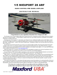
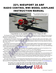
1
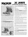
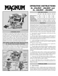
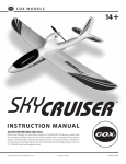
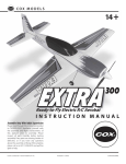
o)
Mirage 2000-5
Electric Powered
Radio Control
Flying Model
Assembly Manual
The Mirage 2000-5 is the latest interceptor jet in a long line of Mirage designs that find their beginnings back in the 1950’s. Speed, maneuverability, and payload capacity put it in a class with the
infamous F-16 and F-18. A delta wing panform and sleek lines make it one fast and agile jet. Our
model of the venerable Mirage is no different. This model adaptation has great slow speed characteristics yet at full throttle, the 400 size electric motor powers this Mirage at amazing speeds. The assembly is very simple which means you will be in the air in no time. 400 size electric aircraft are affordable and fly great yet are very economical to own and operate. We know you’ll enjoy flying this fast
and agile semi-scale pusher jet. Just remember, this plane is quick and not suitable for inexperienced pilots. Thank you for choosing the Mirage 2000-5 for your next project.
Items Needed (Not included in kit)
o) 3 Channel Radio (with mixing or use the Wattage
Electronic Mixer) Hitec Focus 3FM/Micro receiver shown.
o) Micro Servos (CS 10 or 20’s)
o) Speed control for 380 motors with BEC and Auto
cut-off. Some speed controls require additional plugs
o) 6x2, 6x3 or 6x4 propeller (APC or Graupner)
o) Flat 7 or 8 cell 500A or 600AE Nicad battery pack
o) Appropriate battery charger for the flight battery. The
Promax Activator is an AC/DC input, versatile charger.
1
This instruction manual is designed to help you build a straight, great flying airplane. Please read this manual
thoroughly before beginning assembly of your new Mirage 2000-5. Use the parts listing below to identify and
separate all of the parts before beginning assembly.
ÄKIT CONTENTSÃ We have organized the parts as they come out of the box for better identification during
assembly. We recommend that you regroup the parts in the same manner. This will ensure you have all of the
parts required before you begin assembly and will also help you familiarize yourself with each part.
Optional Items
Supplies Needed
Note: Mirage is mostly made of foam. Therefore,
most chemicals will destroy your plane. Only use
recommended chemicals, glues, and paints, and
only use them as described in the directions.
Note: The parts need paint only for appearance.
o) Pactra R/C Car Paint Back (for rear jet
cone)
o)Pactra R/C Car Paint White (for lower fuselage cover and nose cone)
Note: The paint recommended is intended for
the plastic vacuum formed parts ONLY. Do
NOT use this paint on the foam or any part of
the fuselage, wing, vertical, etc.
10) Ruler
11) Crescent Wrench or
8mm nut driver (same
as most glow plug
wrenches)
12) KNS Soldering Iron
and 13) Solder
14) Pen
15) Pliers
Optional:
Magnum Z-Bend Pliers
(not shown)
1) Excell Hobby Knife
2) 3M Masking Tape
3) Kwik Bond 5
Minute Epoxy, Mixing
Sticks and Cups.
4) Paper Towels
5) Scissors
6) #0 Phillips Screwdriver
7) #1 Phillips Screwdriver
8) 1.5mm Hex Wrench
9) Needle Nose Pliers
METRIC CONVERSION CHART
Convert inches into millimeters: Inches x 25.4 = MM
1/64” =
.4mm
1”
=
25.4mm
1/32” =
.8mm
2”
=
50.8mm
1/16” =
1.6mm
3”
=
76.2mm
3/32” =
2.4mm
6”
=
152.4mm
1/8”
=
3.2mm
12”
=
304.8mm
5/32” =
4.0mm
18”
=
457.2mm
3/16” =
4.8mm
21”
=
533.4mm
1/4”
=
6.4mm
24”
=
609.6mm
3/8”
=
9.5mm
30”
=
762.0mm
1/2”
=
12.7mm
36”
=
914.4mm
5/8”
=
15.9mm
3/4”
=
19.0mm
Optional Paint
13)
4)
12)
3)
1)
8)
9)
15)
14)
7)
5)
2)
11)
6)
10)
Global guarantees this kit to be free from defects in both material and workmanship, at the date of purchase. This
does not cover any components parts damaged by use, misuse or modification. In no case shall Global's liability
exceed the original cost of the purchased kit.
In that Global has no control over the final assembly or material used for final assembly, no liability shall be assumed
for any damage resulting from the use by the user of the final user-assembled product. By the act of using the final
user-assembled product, the user accepts all resulting liability.
To make your modeling experience totally enjoyable, we recommend that you get experienced, knowledgable help
with assembly and during your first flights. Your local hobby shop has information about flying clubs in your area
whose membership includes qualified instructors. You can also contact the AMA at the address below.
Academy of Model Aeronautics
5151 East Memorial Drive
Muncie, IN. 47302-9252
(800) 435-9262
www.modelaircraft.org
2
If you should find a part missing or have questions about assembly, please call or write to the address below:
Customer Service Center
18480 Bandilier Circle
Fountain Valley, CA. 92728
Phone: (714) 963-0329
Fax: (714) 964-6236
E-Mail: [email protected]
ÄSUGGESTIONÃ To avoid scratching your new airplane, do not unwrap the pieces until they are needed
for assembly. Cover your workbench with an old towel or brown paper, both to protect the aircraft and to
protect the table. Keep a couple of jars or bowls handy to hold the small parts after you open the bags.
ÄNOTEÃ Please trial fit all the parts. Make sure you have the correct parts and that they fit and are
aligned properly before gluing! This will assure proper assembly. Since the Mirage is, in part, hand made,
every airplane is unique and minor adjustments may have to be made. However, you should find the fit
superior and assembly simple.
Photo 1
o) Fuselage
o) Right Wing Half
o) Left Wing Half
o) Vertical Stabilizer
Kit Contents
Photo 1
Fuselage
Left Wing
Photo 2
o) Sticker Sheet
o) Vacuum Form
o) Molded Parts
(canopy, etc.)
Right Wing
Photo 3
A) Plug Set
B) Motor with leads
and capacitors
C) Wood Motor
Mount Plate
Vertical Stabilizer
Sticker Sheet
D) 3mm Washers (2)
E) 3mm Motor Mounting
Screws (2)
F) Prop adaptor
G) Prop Nut
H) Prop Washer (2)
I) Threaded Rod (2)
J) Nylon Clevis (2)
K) Control Horn Assembly (2)
L) Wood Screw Plates
(6)
M) Wood Screws (6)
K) Two Sided Mounting
Tape.
Photo 2
Photo 3
D)
F)
B)
C)
G)
H)
E)
K)
I)
J)
J)
I)
K)
A)
Vacuum Fo rmed Plastic
Modled Parts Sheet
L)
M)
K)
Wattage guarantees this kit to be free from defects in both material and workmanship, at the date of purchase. This
does not cover any components/parts damaged by use, misuse or modification. In no case shall Wattage's liability
exceed the original cost of the purchased kit.
In that Wattage has no control over the final assembly or material used for final assembly, no liability shall be assumed for any damage resulting from the use by the user of the final user-assembled product. By the act of using the
final user-assembled product, the user accepts all resulting liability.
3
o)6. Spray motor cleaner into the opening on
the side of the motor. The cleaning solution
should be dark in color as it runs out of the motor. Continue spraying cleaner into the motor in
short 1-2 second bursts, 5-6 seconds apart until
the fluid runs clear.
o)7. Apply 2 small drops of oil to each bushing.
o)8. Continue running the motor until the battery dies or 15 minutes, whichever comes first.
o)9. Oil the bushings again. Do not use too much
and wipe away all excess oil.
o)10. Remove the motor from the plane and
repeat these steps every 30 to 40 flights. This
will extend brush life, bushing life, and motor
power output.
Motor Break-In and Radio Prep
For better motor life, follow this section on
motor break-in and maintenance. Even if you
do not break in the motor, follow the steps concerning radio and motor set up.
Items Needed: To break-in the motor, you will
need lightweight oil such as TS Racing oil and
motor cleaner such as Performance Plus III.
Preparation: Please carefully read the
manufacturer’s radio operation directions, the
charger directions, and the speed control (ESC)
directions before attempting to connect power
to any of the electronics.
Performance
Plus III Motor
Cleaner
TS Racing Motor Oil
Apply Oil Here
Mirage Motor
Airframe Preparation
Motor
Rotation
Optional: For better looks, locate two wood
screw plates. Paint them white on one side
only.
Spray
Here
Cleaner
o)1. Remove the internal foam wall between
the cockpit area to the rest of the fuselage. This
area will be for the battery pack.
Special NOTE!: NEVER use these chemicals
on the motor while it is in the plane. NEVER
allow these chemicals to touch the plane in any
way. They will DESTROY your plane beyond
repair and this type of damage is not covered
by warranty.
Remove Foam From This Area
o)1. Charge the flight battery and your radio’s
transmitter battery.
o)2. Connect the motor to the speed control
(ESC) and the ESC to the receiver. Do NOT
connect the propeller or adaptor.
o)3. Connect the radio system and turn on the
transmitter, then the receiver.
o)4. Push the throttle stick to 1/3 throttle. The
motor should begin turning in the clockwise direction (if you are facing the motor’s mounting
surface.) If it turns in the wrong direction, Reverse the MOTOR wires where they connect to
the ESC. Do NOT reverse the polarity of the
battery!
o)5. Apply a small drop of lightweight oil to
the small bushings supporting the motor shaft.
Cocpit Area
o)2. Attach the four screw plates (unfinshed)
to the bottom of the fuselage and the two located on each side of the cockpit with a small
amount of Epoxy. The foam is recessed for the
screw plates.
4
o)2. Trial fit one wing half to the side of the
fuselage. Notice the flat surface of the wing
matches the fuselage side. Align the wing with
the molded wingfoil shape. If the wing shape
does not match the fuselage, try the other wing
half. When properly aligned, the wing halves
cannot be interchanged. Notice the wing halves
will not be twisted if you simply follow the
shape of the wing on the fuselage side and use
the mold lines in the side of the fuselage.
Note: The proper dihedral angle should be
zero. The top of the wing should be flat. From
the factory, however, the correct angle should
be cut into the wing and fuselage mating surfaces.
Install Plates (4)
o)3. Trim the plastic parts. Follow the scribe
lines. (Use drawings)
Cut small (1/4 inch) hole
for battery cooling.
Trim Shaded Area of Canopy
Trim “brim” of the nose cone.
Trial fit on the fuselage.
Match the wing shape with
the fuselage shape.
o)4. If you intend to paint the plastic parts,
paint them now. If you are using the recommended Pactra paint, paint them from the “inside.” Remember to wash and thoroughly dry
the parts before painting.
Paint the tail cone black.
Paint the nose cone white.
Paint the lower fuselage cover white.
Leave all other parts clear.
o)5. Set the parts aside for now.
Align the leading edge and
trailing edge
with the mold
line in the fuselage side
Wing Assembly
o)3. Mix a portion of 5 minute epoxy to attach
the wing half. Only attempt to glue one wing
half to the fuselage at a time. Apply a thin coat
of epoxy to the wing and fuselage surface to be
joined. Hold the wing in place until the glue is
dry.
o)1. Cut out the edges of the elevons on each
wing half. Follow the cutting guides on the bottom surface of the wing. Use a ruler to achieve
a straight cut.
NOTE: The hinge line simply flexes. Do NOT
cut the hinge line.
Motor Installation
o)1. Mount the motor to the firewall with the
machine screws and washers. Trial fit the
motor and firewall in the fuselage. The motor
wires are routed through a factory made hole
in the fuselage. Also notice the cutout area of
the firewall faces down.
o)2. The motor is level with the mold line on
the side of the fuselage. The mold line is the
fuselage centerline.
Hinge Line
(Do NOT cut)
Cut Out Elevon Edges
5
Bottom View
Note: Not all parts shown need to be
installed in this step. Use this drawing
as guide to better understand the
assembly order.
Control Horn
Retaining
Plate
Wood Firewall (motor mount) Plastic Exhaust Cone
Elevon
1.5mm Hex Wrench Set Screw
provided. The head of the servo should be forward and the mounting lugs for the servo should
be past the fuselage side
Motor Screws and Washers
Bottom View
Adaptor Washer Propeller Washer Nut
o)3. Compared to the centerline, the motor
shaft should be angled up 2 degrees.
Control Horns
Angle motor shaft up about 2
degress from the fuselage
centerline.
Use mold line on the
fuselage side as a
guide.
Servo Heads
o)3. Thread the clevis onto the threaded rod
until it just pokes through. This will ensure
plenty of adjustment room.
o)4. Install arms on the servo.
o)5. Center the servo with your radio.
o)6. For level flight, the elevon will be positioned “up” approximately 3/32 inch from neutral.
o)7. Bend the rod as shown. Use the hole in
the servo arm 7/16" from the servo center.
o)4. Epoxy the firewall in position with
epoxy glue. Use tape to hold the firewall in
place while the glue dries. Double check the
thrust angle before the glue dries.
Radio Installation
o)1. The control horns are positioned below
the wing in the recessed area of the elevon. To
mount the horn, use the keeper as a cutting guide
to cut a small slit in the elevon. The horn slides
through the elevon. A small snap keeper retains
the horn. Look closely at the keeper. One side
is beveled and one side is smooth. Slide the
keeper onto the horn beveled side first.
o)2. Mount the servo with the two sided tape
Horn Clevis Threaded Rod
The bend in the pushrod may
only be necessary if you have
placed the servo in toward the
middle of the fuselage.
6
Make Z-Bend
o)8. Temporarily install the motor to the speed
control. Hook up the battery and the radio sys-
tem to run the motor. Looking at the motor, the
shaft should turn clockwise. If it does not turn
clockwise, reverse the motor polarity.
o)9. To reduce the chance of failure as well
as reducing the voltage loss from plugs, we recommend direct soldering the motor wires to the
speed control. However, if you need to use plugs,
Tamiya style plugs have been included in the
kit for your convenience.
o)10. Position the receiver and speed control
as shown. The speed control can be positioned
rearward if needed to prevent radio interference. However, positioning the radio as shown
should help balance the aircraft without the need
for adding weight.
Draw a centerline.
Use the mold
marks as a guide
o)4. Once satisfied with the fit, use epoxy to
glue the stabilizer to the fuselage (The same way
described for the wing.)
90 degrees
Receiver
Reflex Tab Installation
o)1. In order for your Mirage to fly properly, the clear plastic reflex tabs must be installed.
o)2. Trim the tabs as shown. Be sure to leave
a small area (Approx 2mm) around the tab to
act as a gluing surface.
Antenna
Wire
Speed Control
o)11. The plastic cover sets over the radio
compartment. Make small guide holes and then
install the cover with the 4 screws provided.
Leave 2mm
edge around
the tabs
Cover for radio compartment
Match high
point of the
tab with the
wing’s trailing
edge.
Install with 4 wood screws
Cut
Here
Recessed area for launching
grip area
Remove
Shaded Area
Place tab here
Vertical Stabilizer Installation
o)1. The Vertical Stabilizer is mounted on top
of the fuselage. Notice the flat area at the end
of the fuselage.
o)2. To align the stabilizer, draw a centerline
6 7/8" on the fuselage top. Use the foam mold
marks as a guide.
o)3. Test fit the stabilizer. It should be perpendicular to the wing (90 degrees). Lightly
sand the stabilizer mounting-surface if it does
not align properly.
o)3. Test fit the tabs. The tall side should be
aligned with the wing’s trailing edge.
o) 4. Install with epoxy just outside of the
elevons.
7
Note: For best results, you should balance the
propeller. We recommend a propeller normally
made for a "tractor" airplane (engine in front).
Make sure the front of the propeller faces forward. (Looking at the motor from the rear of
the plane, the engine will turn clockwise.)
o) 4. Apply tape to the battery as shown. This
will make it easier to remove the battery.
Finishing Details
o)1. Use the photo and numbering system to
help position the colored trim. Use a long
straight edge or ruler to achieve straight edges
on the decals when you cut them out.
o)2. After the decals are applied, install the
nose cone. Cut the cone from the plastic sheet.
Then test fit the nose cone.
Apply Tape Here
Left Rudder 6-2
Right Rudder 6-1
Right Fuselage 2-1
Left Fuselage 2-2
Top of Fuselage 4
(behind canopy)
Left Leading Edge 1-2
Right Leading Edge 1-1
Nose 5
White
Canopy
Stripe 8
o) 5. Remove the canopy. Install the battery
into the cockpit area.
o) 6. Access the battery plugs through the opening on the fuselage bottom. Push the connectors
into the fuselage once connected.
Red Scoop Strip
Left Fuselage 3-2
Right Fuselage 3-1
Intake Ring
Left 7-2
Right 7-1
o)3. Install the nose cone with epoxy glue.
o)4. Find the exhaust cone. Trim the edges and
open the screw holes. Do not oversize the openings.
o)5. Remove the motor screws and install the
cone with the motor screws. See Drawing on
Page 6.
o) 6. Install the canopy with the small screws
provided (in the same manner as the lower radio cover.)
Balance
o) 1. For proper flight, the Mirage must be balanced. The balance point is 130mm to 150mm
back from the leading edge at the fuselage side.
o) 2. Move the battery or radio to achieve the
proper balance.
Balance Point
130 to 150mm behind the
wing’s leading edge at the
fusealge side.
130mm will create a more
stable jet at slow speeds
Propeller and Battery Installation
150mm will create a faster
jet but with a higher stall
speed.
o) 1. Find the propeller adapter.
o) 2. Install the adapter with the 3mm set screw
(you will need a 1.5mm hex wrench.) Leave 1/
8 inch space between the adapter and the plastic cone.
o) 3. Install the propeller with the nut provided.
8
Radio Set-up and Control Throws
Position elevator trim in the neutral
position. Then adjust the linkage to
bring the elevon up 1-2 mm
Trimming for Best Performance
o ) 1. Neutral
elevon is 2 mm
up at the inner
edge.
Fine tuning the balance point (CG) and elevon
neutral point will result in better, more predictable flight characteristics.
To trim the Mirage, bring the plane into level
flight from a shallow dive.
Elevon is
up 1-2 mm
for
level
flight.
During the level flight portion, watch the plane.
If it climbs, try reducing the amount of “up”
elevon. If you have little or no “up” elevon, try
moving the battery back 1/4 inch.
o) 2. Right stick should make the right elevon
move up and the left elevon move down.
o) 3. Forward stick should make both elevons
move down.
o) 4. If the controls do not work in the proper
direction, check your radio's servo reversing.
o) 5. For your first flight, set the control throws
to approximately 5/16 inches up and 5/16 inches
down. Once you have become familiar with the
plane, you may increase the throws to as much
as 9/16 inches. If you have a computer radio,
increase the aileron travel first. The elevator
will be sensitive enough at 5/16 inches for most
manuevers.
If the Mirage dives, increase the amount of “up”
elevon. If you have more than 2mm up elevon,
move the battery pack forward 1/4 inch.
This procedure will decrease drag and keep
the pitch sensitivity “in the envelope.”
If it climbs, reduce the up elevon
Launching
If it dives, increase the up elevon
Throw the Mirage with the wings level (from
right to left.) The fuselage should be level to
the ground. The model should be thrown with
the motor off. Immediately after launch, apply
power and maintain level flight for 40-60 feet
to build up airspeed. Launching with the motor
off will help prevent the propeller from striking your hand causing serious injury.
Choosing to Fly and Pre-Flight Check
Do not fly near powerlines, obstacles, or around
people. The Mirage is not a toy and can cause
harm or injury.
Do not fly if it is windy. Pick a calm day for your
first flights. Attach a 8 inch long, by 1 inch wide
piece of ribbon to your antenna with string. If the
wind blows it out more than 45 degrees from the
antenna, the wind is blowing too hard.
Always launch into the wing and do not fly in
high winds. For your first flights, fly the Mirage in calm weather to prevent accidents until
you become familiar with the model.
Properly charge your transmitter and flight batteries. Weak batteries cause crashes.
Hold Plane Level
ok
Double check control movement direction and
throws.
Range test the radio before your first flight. Perform power-on range tests before your first flight.
9
Motor Maintenance
Battery Use
For longer motor life and better performance,
regular cleaning is necessary. Follow these
steps for regular maintenance.
1. Remove the propeller and propeller assembly. Then remove the motor from the airplane.
Leave the motor leads attached to the speed
control.
2. Cover the tail of the fuselage with plastic
wrap to prevent solvents from touching the foam.
NOTE: Foam will melt and be destroyed by
motor cleaners and some oils. Take great caution when using these products.
3. Spray cleaner onto the motor commutator until
the cleaner runs clear. This is best done outdoors with good ventilation.
4. Place a small drop of oil on each end of the
motor shaft.
5. Run the motor at 1/3 throttle. Spray a little
more cleaner onto the motor.
6. Turn off the motor and re-oil the bushings at
each end of the shaft.
7. Install the motor back in the plane and install
the prop. It’s that simple.
This process keeps the motor bushings lubricated and the commutator clean. Complete
this task every 30 to 40 flights for best performance.
Good battery usage and maintenance is crucial
for the great performance you expect from your
new Mirage.
Much has been written about Nickel Cadmium
battery care and maintenance. Indeed you can
find much information in magazines and on the
internet. While small details can make slight
differences in battery performance, here are a
few tips that most will agree help batteries sustain their best performance.
1. Use a peak detector (or Delta Peak) charger.
This type of charger is the only way to ensure
your battery is properly charged each flight and
does not overcharge the battery.
2. Choose a charger that is designed for your
exact battery size or has adjustable output current. The small batteries most commonly used
in 400 size planes need to be charged at no more
than 2 time their rated amperage. Therefore, a
Sanyo 600AE battery should not be charged at
more than 1200 mah (or 1.2 amps). While some
charge at a higher rate, staying below the “twice
factor” will ensure long life.
3. Let the batteries cool before charging. After
a flight, the battery becomes very warm and
sometimes very hot. NEVER charge a hot battery. If you first let it cool, it will take more
charge and give better performance.
4. Discharge the battery to 1.05 volts per cell.
(example: for a 7 cell battery, that would be
:7.35 volts.) Every use or at least very regularly, discharge the battery to this level. Let the
battery cool, and then charge the battery. Some
discharge their batteries to a lower voltage.
However, discharging the battery below this
point can lead to cell damage, especially in cells
that are not “matched”. Deans and Astro Flight
make discharges that will discharge the battery
and automatically shut off at a safe voltage.
5. After each flight, touch the battery. If it is
excessively hot after the flight, examine the motor. It may have a bad component. A malfunctioning motor can draw 2-5 times normal current.
Keep track of your motor.
Date cleaned:
10
ODUCT EV
ALU
ATION SHEET
RODUCT
EVA
UA
PR
Telling us what you like and don't like determines what model kits we make and how we make them. We
would appreciate it if you would take a few minutes of your time to answer the following questions about this
kit. Simply fold this form on the dotted lines, seal with tape and mail it to us. Do not use staples and make
sure our address faces out.
1) Kit:
7) Was any of the assembly difficult for you? If
yes, please explain.
q Yes
q No
_____________________________________
_____________________________________
_____________________________________
_____________________________________
Wattage Mirage 2000-5
2) Where did you learn about this kit?
q Magazine Ads
q Friend
q Hobby Shop
q Other
q Internet
3) What influenced you the most to buy this kit?
q Magazine Ads
q Price
q Type of Model
q Box Art
q Recommendation
q Other
q Internet
8) What did you like most about this kit?
q Assembly Manual
q Parts Fit
q Hardware Supplied q Price
q Other
_____________________________________
_____________________________________
_____________________________________
4) Did you have any trouble understanding the
written instructions? If yes, please explain.
q Yes
q No
_____________________________________
_____________________________________
_____________________________________
_____________________________________
9) What did you like least about this kit?
q Assembly Manual
q Parts Fit
q Hardware Supplied q Price
q Other
_____________________________________
_____________________________________
_____________________________________
5) Did you have any trouble understanding any of
the photographs. If yes, please explain.
q Yes
q No
_____________________________________
_____________________________________
_____________________________________
_____________________________________
10) Are you satisfied with the finished model? If
no, please explain.
q Yes
q No
_____________________________________
_____________________________________
_____________________________________
_____________________________________
6) Were any of the kit parts:
q Damaged
q Wrong Size
q Missing
q Wrong Shape
If you checked any of the boxes above, did you
contact our Customer Service Department to re
solve the problem?
q Yes
q No
11) How does this kit compare to similar kits by
other manufacturers?
q Better Than
q As Good
q Not as Good
Additional Comments: _________________________________________________________________
_____________________________________________________________________________________________
_____________________________________________________________________________________
_____________________________________________________________________________________
_____________________________________________________________________________________
11
Fold along dotted line
Post Office
will not
deliver
without
proper
postage
Complete Return Address Information Here
Watt Age
Attn: Customer Service Department
18480 Bandilier Circle
Fountain Valley, CA. 92728
Fold along dotted line
12