1
rlon
•
®
Owner's manual
Mode d'emploi
Manual de instrucciones
f£ffj itt fj/j =Ii
DXZ925
HIGHEND AM/FM RADIO CD PLAYER COMBINATION
•
COMBINE CD RADIO FM/AM HAUT DE GAMME
•
020DXZ925
COMBINACION DE RADIO DE AM/FM YREPRODUCTOR
DE DISCOS COMPACTOS DE ALTA POTENCIA
•
renNET
r£lCOMPACT
~_=_~_.=-=;= [](J
IDOLBY I L!!JD~(lli
~.
SURROUND
Ip·'••••,ij'....
DIGITAL AUDIO
I TEXT
;ct.-\/
~,
SIRIUS
IRE A 0 V
Thank you for purchasing this Clarion product.
* Please read this owner's manual in its entirety before operating this equipment.
* After reading this manual, be sure to keep it in a handy place (e.g., glove compartment).
* Check the contents of the enclosed warranty card and keep it carefully with this manual.
* This manual includes the operating procedures of the CD changer, MD changer, DVD changer, AUX,
DAB, DSP DVD, PHONE MUTE and TV tuner connected via the CeNET cable. The CD changer, fJlD
changer, DVD changer and TV tuner have their own manuals, but no explanations for operating them
are described.
Contents
1. FEATURES
2. PRECAUTIONS
Dual Action
Handling Compact Discs :
3. CONTROLS
4. NOMENCLATURE
Names of the Buttons and their Functions
Major button operations when external equipment is connected to this unit
Display Items
LCD Screen
5. REMOTE CONTROL
Names of Parts..........................................................................................................................
Functions of Remote Control Unit Buttons
Loading Battery
Attaching the Remote Control Unit to the Steering Wheel
6. DCP
7. OPERATIONS
Basic Operations
AC-Processor II Operations
Radio Operations
CD Operations
Operations Common to Each Mode
8. OPERATIONS OF ACCESSORIES
CD/MD/DVD Changer Operations
TV Operations
Digital Radio/DAB Operations
DVD DECK Operations
9. IN CASE OF DIFFICULTY
10. ERROR DISPLAYS
11. SPECiFiCATIONS
2
3
3
4
5
6
6
7
9
9
10
1G
10
10
11
1:2
13
13
15
18
20
21
24
24
26
27
31
32
33
133
1. FE1l7URE!
:.:.:.:.::::::::::::::::::::::::::::::::::::::::::::::::::::::::::::::
::::::::::::::::::::::::::::::::::::::::::::::::::::;:;::::::::::; .
• Dual Action··Deta.chableAlminumFace
• Rotary Encorder volume Control
• AC-Processor II including Dolby Pro Logic II
for user like sound making
• Controller for Optional DAB, SIRIUS, TV Tuner
CD, MD, DVD Changer, DVD Deck, B.B.DTS
• 4V/4-Channel RCA LineLevel Output with
Fader Control
• Capability to Read CD TEXT Data, CD-R,CDRW
• 2-Channel RCA AUX Input
• 200W(50Wx4) Maximum Power Output
• CeNET with Balanced Audio Line Transmission
and Dynamic Noise Cancelling
•
2
mR61:rUNE~® FM Reception System
DXZ925
2. PRECAUTIONS
1. When the inside of the car is very cold and the
player is used soon after switching on the
heater moisture may form on the disc or the
optical parts of the player and proper playback
may not be possible. If moisture forms on the
disc, wipe it off with a soft cloth. If moisture
forms on the optical parts of the player, do not
use the player for about one hour. The condensation will disappear naturally allowing normal
operation.
2. Driving on extremely bumpy roads which cause
This equipment has been tested and found to comply with the limits for a Class B digital device, pursuant to Part 15 of the FCC Rules.
These limits are designed to provide reasonable
protection against harmful interference in a residential installation.
This equipment generates, uses, and can radiate
radio frequency energy and, if not installed and
used in accordance with the instructions, may
cause harmful interference to radio communications. However, there is no guarantee that interference will not occur in a particular installation.
If this equipment does cause harmful interference
to radio or television reception, which can be determined by turning the equipment off and on, the
user is encouraged to consult the dealer or an experienced radio/TV technician for help.
severe vibration may cause the sound to skip.
3. When the auto antenna cord is connected to
the car auto antenna cord, when the unit is
switched to the radio mode (or the TV mode),
the antenna is extended automatically. If the car
is in a narrow space, the antenna may strike
something, so be careful.
4. This unit uses a precision mechanism. Even in
the event that trouble arises, never open the
case, disassemble the unit, or lubricate the rotating parts.
USE OF CONTROLS, ADJUSTMENTS, OR PERFORMANCE OF PROCEDURES OTHER THAN
THOSE SPECIFIED HEREIN, MAY RESULT IN
HAZARDOUS RADIATION EXPOSURE.
THE COMPACT DISC PLAYER and MINI DISC
PLAYER SHOULD NOT BE ADJUSTED OR REPAIRED BY ANYONE EXCEPT PROPERLY
QUALIFIED SERVICE PERSONNEL.
CHANGES OR MODIFICATIONS NOT EXPRESSLY APPROVED BY THE MANUFACTURER FOR COMPLIANCE COULD VOID THE
USER'S AUTHORITY TO OPERATE THE EQUIPMENT.
CHANGES OR MODIFICATIONS TO THIS PRODUCT NOT APPROVED BY THE MANUFACTURER WILL VOID THE WARRANTY AND WILL
VIOLATE FCC APPROVAL.
I
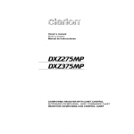
MODEL
12V
8
clarion
GROUND
AM 530-1710kHzlFM 87.9-107.9MHz
THIS DEVICE COMPLIES WITH PART 15 OF THE FCC RULES
OPERATION IS SUBJECT TO THE FOLLOWING TWO CONDITIONS:
(1) THIS DEVICE MAY NOT CAUSE HARMFUL INTERFERENCE AND
(2) THIS DEVICE MUST ACCEPT ANY INTERFERENCE RECEIVED
~;~~~~~~. INTERFERENCE THAT MAY CAUSE UNDESIRED
THIS PRODUCTION COMPLIES WITH DHHS RULES 21 CFR
SUBCHAPTER J APPLICABLE AT DATE OF MANUFACTURE.
CLARION CO.,LTO.
50 KAMITODA,TODA-SHI,SAITAMA-KEN,JAPAN
C 051
o
722 877
MANUFACTURED
[:==J
SERIAL No
c==::J
Clarion Co. ,Ltd
I
Bottom View of Source Unit
DXZ925
3
Dual Action
This unit uses Dual Action to make large-screen
displays possible.
When you use the Dual Action, be sure to close
it.
2. Before the DUAL ACTION closes, there may
be a braking sound from the safety mechanism. This is normal.
3. If you move the DUAL ACTION by hand, this
may create play. To correct this play, with the
power on for the unit, press the [0] button to
close the DUAL ACTION.
4. After a disc is ejected, the DUAL ACTION automatically returns to the tilted or closed
state. If there is any obstruction when the
DUAL ACTION tries to close, the safety
mechanism is triggered and the DUAL ACTION returns to the open state. If this happens, remove the obstruction, then press the
[0] button.
5. To avoid scratching the compact disc, keep
the 12 or 8 cm CD level when inserting or removing them.
Handling Compact Discs
Use only compact discs bearing the lillo~@ or
•
mark.
DIGITAL AUDID
Do not play heart-shaped, octagonal, or other
specially shaped compact discs.
Some CDs recorded in CD-R/CD-RW mode may
not be usable.
Handling
• Compared to ordinary music CDs, CD-R and CDRW discs are both easily affected by high temperature and humidity and some of CD-R and
CD-RW discs may not be played. Therefore, do
not leave them for a long time in the car.
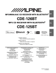
• New discs may have some roughness around
the edges. If such
discs are used, the
Ball-point pen
player may not work
or the sound may
_R_ou~g_hn_es_s
.~~,.""..,
skip. Use a ball-point
pen or the like to remove any roughness
from the edge of the
disc.
• Never stick labels on the surface of the compact
disc or mark the surface with a pencil or pen.
• Never playa compact disc with any cellophane
tape or other glue on it or with peeling off
marks. If you try to play such a compact disc,
you may not be able to get it back out of the
CD player or it may damage the CD player.
• Do not use compact discs that have large
scratches, are misshapen, cracked, etc. Use of
such discs may cause misoperation or damage.
• To remove a compact disc from its storage case,
press down on the center of the case and lift the
disc out, holding it carefully by the edges.
• Do not use commercially available CD protection sheets or discs equipped with stabilizers,
etc. These may damage the disc or cause
breakdown of the internal mechanism.
Storage
• Do not expose compact discs to direct sunlight
or any heat source.
• Do not expose compact discs to excess humidity or dust.
• Do not expose compact discs to direct heat
from heaters.
Cleaning
• To remove fingermarks and dust, use a soft
cloth and wipe in a straight line from the center
of the compact disc to the circumference.
• Do not use any solvents, such as commercially
available cleaners, anti-static spray, or thinner
to clean compact discs.
• After using special compact disc cleaner, let
the compact disc dry off well before playing it.
Be sure to unfold and read the next page. / Veuillez depUer et vous referer it la page suiv8nte.
Cerciorese de desplegar y de leer fa pagina siguiente.
/,
OXZ925
~
4
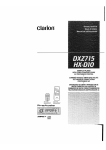
Source unit / Appareil pilote / Unidad fuente / ~ III
[FNC]
"'------,===:;>
~-~[O]
~-~[DISP]
~~~~ [A-M]
~=~[RD]
With the Dual Action opened / Lorsque la Double action est Duverte
Con el panel frontal de accion doble abierto / j.xiJJf1=*fl*~HJi5~x~
Note: Be sure to unfold this page and refer to the front diagrams as you read each chapter.
Remarque: Veuif/ez daplier cette page et vous refarer aux schemas quand vous iisez cheque chap/ire.
Nota: Cuando lea los capitulos, despliegue esta pagina y consu/te los diagramas.
;~Jl
5
: /fQiJiif$iflifif!f%:f!;J!iJF7fKJJ[# fj§:J1!;fli/J l!J![fJo
DXZ925
4. NOMENCLATtJRE
Note:
• Be sure to read this chapter referring to the front diagrams of chapter u3. CONTROLS" on page 5 (unfold).
Names of the Buttons and their Functions
[RELEASE] button
[RP] button
• Deeply press the button to remove the DCP.
• Plays repeatedly while in the CD mode.
[VSE] button
[SC] button
• Press to enter VSE mode or the Position
mode.
• Performs preset scan while in the radio mode.
When the button is pressed and held, auto
store is performed.
• When the button is pressed and hold for 1 second or longer, the mode is turned on or off.
[EQ] button
• Performs scan play for 10 seconds for each
track while in the CD mode.
• Press to enter the EO mode.
[BND] button
• When the button is pressed and hold for 1 second or longer, the mode is turned on or off.
• Switches the band, or seek tuning or manual
tuning while in the radio mode.
[FNC] button
• Plays a first track while in the CD mode.
[TITLE] button
• Press the button to turn on the power.
Press and hold the button for 1second or
longer to turn off the power.
• Use the button to input a title in the CD mode
and radio mode.
• Switches the operation mode among the radio mode, etc.
• Press and hold the button for 1 second or
longer to enter the adjust mode.
[SAT] button
• This button is available only when the unit is
connected with Satellite Digital Radio Tuner
(sold separately DSH920S).
[<<11III], [~>] buttons
• Selects a station while in the radio mode or
selects a track when listening to a CD. These
buttons are used to make various settings.
[~II]
[ROTARY] knob
button
• Plays or pauses a CD while in the CD mode.
• Used as "Enter button" while the unit is in the
ADJ mode.
• Adjust the volume by turning the knob clockwise or counterclockwise.
• Use the knob to perform various settings.
[0] button
[PLll] button
• Use the button to open the dual action.
• Press to select the Dolby Pro Logic II mode.
[DISP] button
[DIRECT] button
• Switches the display indication (Main display,
clock display).
• Stores a station into memory or recall it directly while in the radio mode.
[A-M] button
[CD SLOT]
• Use the button to switch to the audio mode
(balance/faderlsub.w/center SP/NF. adjustment)
• CD insertion slot.
[RD] button
• Press to open the CD slot and insert a CD.
• Performs random play while in the CD mode.
[ISR] button
• Recalls ISR radio station in memory.
• Press and hold for 2 seconds or longer:
Stores current station into ISR memory (radio
mode only).
6
DXZ925
[CD EJECT] button
• Press to eject a CD loaded in the unit.
[RESET] button
• Press to reset the system.
Major button operations when external equipment is
connected to this unit
_ When the CD/MD/DVD changer
is connected
*
For details, see the section "CD/MD/DVD
changer operations". For the DVD
changer, refer to the Owner's Manual provided with the DVD changer.
[SC] button
[RP] button
• Press the button to turn on or off the AF (Alternative Frequency) function in the DAB mode.
(This function is only DAB tuner.)
[RD] button
• Use the button to set the PTY (Programme Type)
standby mode or PTY items in the DAB mode.
• Performs scan play for 10 seconds for each
track. Disc scan play is performed when the
button is pressed and held.
• Switches the TV picture mode or VTR (external)
picture mode.
[RP] button
• Stores a station into memory or recall it directly.
• Performs repeat play. When this button is
pressed and held, disc repeat play is performed.
[<<llIII],
[RD] button
• Performs random play. Also performs disc random play when the button is pressed and
held.
[DIRECT] button
• Designates the disc to be played.
[DISP] button
• Switches the clock or selects the title mode.
• When the button is pressed and held, the user
titles or disc titles are switched.
[TITLE] button
• Use the button to input a title in the CD
changer mode.
• Use the button to scroll the title during CD-text
play or MD changer play in the CD changer mode.
I~II]
button
• Plays or pauses a CD, MD or DVD.
[<<llIII], [~>] buttons
\ • Selects a track when listening to a disc.
[DIRECT] button
[~>] buttons
• Selects a station.
[BND] button
• Switches the band.
• When the button is pressed and held,
switches seek tuning or manual mode.
_ When the DTS/DOLBV DIGITAL
is connected
[VSE] button
• Press the button to turn on the DSF.
• After DSF is selected, press and hold the
[VSE] button for 1 second or longer to turn to
off DSF effect.
[PLll] button
• Press the button to turn on the PLII, and each
time to press PLII mode changes following order:
Music mode ~ Matrix mode ~ Movie mode
~ Virtual mode ~ mode off
[BND] button
• Plays a first track.
• Used as "disc up button" while the unit is in
the DVD changer mode.
_When the TV/DAB is connected
*
For details, see the section "TV operations" or "DAB operations".
[SC] button
• Used to perform preset or category scan
while the unit is in the radio mode. When the
button is pressed and held, auto store is
performed.(This function is available only in
the TV tuner mode.)
DXZ925
7
\/
~,-
e When the Sirius Satelite Radio
is connected
* For details, refer to the Owner's Manual
provided with the Sirius Satelite Radio.
[FNC] button
• Press the buton to switches the operation
mode among the SIRIUS mode, etc.
[SC] button
• Press the button to preform category scan
while in the SIRIUS mode.
• Press and hold the button to perform preset
scan while in the SIRIUS mode.
[DIRECT] button
• Stores a station into memory or recall it directly while in the SIRIUS mode.
[<~], [~>] buttons
• Press the buton to selects a station.
[SAT] button
• Press the buton to switches the SIRIUS
mode.
What is Sirius Satellite Radio? ~tle~!~d~,
Sirius is radio the way it was meant to be: Up to
100 new channels of digital quality programming
delivered to listeners coast to coast via satellite.
That means 50 channels of completely commercial-free music. Plus up to 50 more channels of
news, sports, and entertainment from names
like CNBC, Discovery, SCI-FI Channel, A&E,
House of Blues, E!, NPR, Speedvision and
ESPN.
Sirius is live, dynamic entertainment, completely
focused on listeners. Every minute of every day
of every week will be different. All 50 commercial-free music channels are created in-house
and hosted by DJs who know and love the music. Do you like Reggae? How about Classic
Rock or New Rock? Sirius has an array of
choices spanning a vast range of musical tastes "
including the hits of the 50's, 60's, 70's, & 80's
as well as Jazz, Country, Blues, Pop, Rap, R&B,
Bluegrass, Alternative, Classical, Heavy Metal,
Dance and many others...
~
~
From its state-of-the-art, digital broadcasting facility in Rockefeller Center, New York City, Sirius
will deliver the broadest, deepest mix of radio
entertainment from coast to coast.
Sirius will bring you music and entertainment
programming that is simply not available on traditional radio in any market across the country.
It's radio like you've never heard before.
So Get Sirius and Listen Up! For more information, visit siriusradio.com.
8
DXZ925
Display Items
(CmillJ») : DAB indication
~
: Alternative frequency indication
. , . : Traffic announcement indication
E2 : Traffic programme indication
aiD : Programme type indication
I1l1E : Information indication
~ : Mute indication
~
: Satellite indication
SAT
Operation status indication
Titles, Clock, etc. are displays.
o
,./~ch;'•. '~qUBLE
NICE PllnEL SYSTEm
•
[,~
••
••
.(~IDABlrhJ2IW/;f;~fjli/~1IW~~:I_IJ1JII~~:"
:
",,:S_
.• •.•
DOL_BYPLU-----..
~:
(mll!J:
Stereo indication
Manual indication
Function mode indication
The names of modes being
selected,etc.are displayed.
Preset channel indication (1 to 6)
Disc number indication (1 to 12)
_
:Disc indication
_
:Scan indication
_
:Repeat indication
_
:Random indication
I
1_ :
l_ :
1:0 .•
Music mode indication
r _
:
Matrix mode indication
Movie mode indication (indicate within 8.8. DTS/DOL8Y DIGITAL)
! _
: Virtual
mode indication (indicate within B.B. DTS/DOLBY DIGITAL)
44"*' : VSE
~
indication (VSE: Virtual Space Enhancer)
: Parametric Equalizer indication
CDOLBY PLII:::J :
Dolby Pro Logic II indication
: DTS indication (indicate within B.B. DTS/DOLBY DIGITAL)
LCD Screen
In extreme cold, the screen movement may slow down and the screen may darken, but this is normal.
The screen will recover when it returns to normal temperature.
DXZ925
9
Names of Parts
Joystick
... T Volume control
<.... ~> Search
FNC (function)/
POWER (power) button
BND
BND (Band) button
Top button
Disc Up button
Program button
Functions of Remote Control Unit Buttons
CD/MDchanger
DVDchanger
CD
TV
[FUNC]
Switches among radio, DAB, SIRIUS, CD, DVD deck, CD/MD changer, DVD changer, TV,
and AUX.
[BAND]
Switches reception
band.
Plays the first track.
Top play.
Moves the next disc
in increasing order.
Switches reception
band.
Increases and decreases volume (in all modes).
[<~]
, [~>]
Moves preset
channels up and
down.
Moves tracks up and down.
When pressed and held for 1 second:
Fast-forward/fast-backward.
* Some of the corresponding buttons on the main unit and remote control
Moves preset
channels up and
down.
unit have different functions.
Loading Battery
1. Open the battery cover.
2. Insert the supplied lithium battery (CR2032) with the plus
cover.
o
EB symbol facing
(±) - ; / Lithium battery
e
0.·,1··
o '.. .;; .
...:-:>::---}:
10
DXZ925
up and close the battery
Loading Battery
Notes:
Using batteries improperly can cause them to explode. Take note of the following points:
• Do not short-circuit, disassemble or heat batteries.
• Do not dispose of batteries into fire or flames.
• Dispose of spent batteries properly.
Attaching the Remote Control Unit to the Steering Wheel
1. Attach the holder to the steering wheel.
The diagrams below show how to install the remote control unit on the steering wheel of a car with
the steering wheelan the Left. Install the remote control unit on the Left in a car with the steering
wheelan the right side.
Attachment to a left hand drive car
Holder
2. Installing the steering wheel remote control unit
Attachment to a left hand drive car
Attachment to a right hand drive car
Steering wheel remote control unit
Steering wheel remote control unit
Holder
Screw with washer (2.6
x 5)
~
~
Attachment to a left hand drive car
Screw with washer (2.6 X 5)
Attachment to a right hand drive car
Align
Sooering wheel remote control unit ~
~---------'~=~- Steering wheel remote control unit
'Holder
Clearance
Note:
The location to be chosen for the remote control unit depends on the configuration of the steering wheel.
Make sure that the installation of the remote control unit does not prevent normal driving and that the remote
control signal reaches the remote control sensor.
DXZ925
11
The control panel can be detached to prevent
theft. When detaching the control panel, store it
in the DCP (DETACHABLE CONTROL PANEL)
case to prevent scratches.
We recommend taking the DCP with you when
leaving the car.
Removing the DCP
1. With the DUAL ACTION closed, turn off the
power.
2. Press the [RELEASE] button deeply and
take and pull the DCP to detach the DCP.
ing the DCP.
• If you remove the DCP with the DUAL ACTION
open, the sloping console closes immediately.
Be careful not to get your fingers caught.
• The DCP can easily be damaged by shocks.
After removing it, be careful not to drop it or
subject it to strong shocks.
• If the [RELEASE] button is pressed and the
DCP is not locked into place, it may fall out
from vibration of the car. This can break the
DCP, so after removing it, either install it on '
the unit or put it in its DCP case.
• The connector connecting the unit and the
DCP is an extremely important part. Be car.eful
not to damage it by pressing on it with finr1er
nails, screwdrivers, etc.
ocP-
a
Attaching the DCP
1. Insert the DCP so that the ® section on the
right side of the DCP catches on the hook ®
on the unit.
• If you apply to the control panel more force
than that required with the control panel left
open, the control panel will go down one step.
This is due to safety mechanism engaged and
is not a malfunction. In this case, press the [0]
button two times to return the control panel to
the original operating position. Using the control panel being lowered results in a damage
to the panel.
• Do not use the control panel being left open
as a tray to put an object on.
• Moving the control panel manually will cause a
malfunction such as getting out of order of the
sloping mechanism, breakdown of the gears,
etc. Do not draw the control panel forcibly.
oCP -
®
2. Press the left side
fit it in place.
@
© of the DCP carefully to
When the control panel is moved manually,
press the [0] button several times to see if the
control panel returns to the normal position
and functions properly.
• Do not remove the DCP while you are driVing
a car.
• Do not use the DCP being rickety.
• Do not carry the DCP in a trouser pocket or
the like directly. (The DCP may be damaged
under load conditions.)
• The DCP may jump out of the DCP case housing the DCP when the case is opened energetically.
Note:
• If the OCP is dirty, wipe off the dirt with a soft, dry
cloth only.
12
OXZ925
Basic Operations
Note: Be sure to read this chapter referring to the front diagrams of
chapter "3. CONTROLS" on page 5 (unfold).
Adjusting the volume
Be sure to lower the volume before switching off the unit power or the ignition key. The
unit remembers its last volume setting. If you
switch the power off with the volume up,
when you switch the power back on, the sudden loud volume may hurt your hearing and
damage the unit.
Turning on/off the power
Note:
• Be careful about using this unit for a long time
without running the engine. If you drain the car's
battery too far, you may not be able to start the
engine and this can reduce the service life of the
battery
1. Press the [FNC] button.
2. The illumination and display on the unit light
up. The unit automatically remembers its last
operation mode and will automatically switch
to display that mode.
3. Press and hold the [FNC] button for 1 second
or longer to turn off the power for the unit.
Note:
• System check
The first time this unit is turned on after the wire
connections are completed, it must be checked
what equipment is connected. When the power is
turned on, "SYSTEM CHCK" and "Push Power"
ar;pear in the display alternately, so press the
[FNC} button. The system check starts within the
unit. When the system check is complete, the
power is turned off, so press the [FNC} button
flgain.
Selecting a mode
1. Press the [FNC] button to change the operation mode.
2. Each time you press the [FNC] button, the
operation mode changes in the following order:
Radio mode -+ DAB mode -+ SIRIUS mode
-+ CD mode -+ DVD DECK mode -+ CD
changer mode -+ MD changer mode -+ DVD
changer mode -+ TV mode -+ AUX mode -+
Radio mode ...
:;: External equipment not connected with
CeNET is not displayed.
Turning the [ROTARY] knob clockwise increases
the volume; turning it counterclockwise decreases the volume.
* The volume level is from 0 (minimum) to 33 (maximum).
SWitching the display
Press the [DISP] button to select the desired
display.
Each time you press the [DISP] button, the display switches.
* Once selected, the preferred display becomes
the display default. When a function adjustment such as volume is made, the screen will
momentarily switch to that function's display,
then revert back to the preferred display several seconds after the adjustment.
* When you have entered a title in a CO/MO, it
appears in the main display. If you have not
entered a title, "[Q] NO-TITLE" or "IT] NOTITLE" appears in the title display instead. For
information on how to enter a title, refer to the
subsection "Entering titles" in section "Operations Common to Each Mode ".
Setting the clock
1. Press and hold the [TITLE] button for 1 second or longer to enter ADJ mode.
2. Press the [<~] or [~>] button to select the
"CLOCK".
3. Press the [~II] button.
4. Press the [<~] or [~>] button to select the
hour or the minute.
5. Turn the [ROTARY] knob clockwise or counterclockwise to adjust the correct time.
:;: The clock displayed in 12-hour format.
6. Press the [~II] button to store the time into
memory.
7. Press the [TITLE] button to return to the
previous mode.
Note:
• You cannot set the clock when it is displayed with
only the ignition on. If you drain or remove the
car's battery or take out this unit, the clock is reset. While setting the clock, if another button or
operation is selected, the clock set mode is canceled.
DXZ925
13
Basic Operations
Adjusting the balance
channel (subwoofer).
1. Press the [A-M] button and select "BALANCE".
If you using Dolby Pro Logic source and your
speaker is only four Front L.R. + Surround L.R.,
speaker setting will be better to CTR+SW and
CTR OFF, so Center channel divided to Front
L. R. automatically.
2. Turning the [ROTARY] knob clockwise emphasizes the sound from the right speaker;
turning it counterclockwise emphasizes the
sound from the left speaker.
* The factory default setting is "0". (Adjustment
range: L13 to R13)
3. When the adjustment is complete, press the
[A-M] button several times until the function
mode is reached.
Adjusting the fader
1. Press the [A-M] button and select "FADER".
2. Turning the [ROTARY] knob clockwise emphasizes the sound from the front speakers;
turning it counterclockwise emphasizes the
sound from the rear speakers.
* The factory default setting is "0".
(Adjustment
range: F12 to R12)
3. When the adjustment is complete, press the
[A-M] button several times until the function
mode is reached.
Operation BASSffREB
1. Press the "BASSITREB" mode. Each time
the [EQ] button is pressed, the adjusting item
"BASS" or "TREB" is changed cyclically.
2. Turn the [ROTARY] knob clockwise or counterclockwise to adjust "BASITREB".
3. Press the [EQ] button to return to the previous mode.
* The Adjustment range is from
-6dB to +6dB
for bass and treb.
* This parameter is reflected STO PRO mode
Speaker Setting
You can set up your favorite sound environment
using "Dolby Surround Pro logic n" or "ACProcessor n" so that you can enjoy a dynamic
sound of 5.1 ch surround or 4ch + 2ch speaker.
.Dolby Pro Logic
n 5.1ch surround
Center SP +Front L. R. +Surround L. R. +Sub
Woofer.
To make the most of the sound field reproduction of Dolby Pro Logic IT, a speaker system of
5.1 channel is recommendable. It has been also
designed so that a sound filed effect almost as
good as that of 5.1 channel reproduction can be
obtained even by a constitution of 4 channel + 1
14
DXZ925
Note
• When SW-L + SW-R are chosen, audio output
from SW-L is not available in the PL II mode.
.AC-Processor n
Front L.R. + Rear L.R.+ Sub Woofer L.R. (4ch +
2ch)
"
To make the most of the sound field reproduction of AC-Processor IT, a speaker system of 4
channel + 2 channel is recommendable.
1. Press and hold the [TITLE] button for 1 socond or longer and enter "ADJ" mode.
2. Press the [<~] or [~>] button to select the
"SP-SETTING".
3. Turn the [ROTARY] knob clockwise or counterclockwise to select "SW L+SW R" or "CTR
+SW" mode.
Note:
• When CTR + SWare chosen, audio output from
CTR is not available except in the PL II mode.
Center Speaker and Sub Woofer On / Off
Select PLIT Mode on and SP setting to
"CTR+SW" mode
1. Press and hold the [TITLE] button for 1 second or longer.
2. Press the [<~] or [~>] button to select the
"SPSEL".
3. Press the [~II] button to adjust the "CTRSP""SUBW".
4. Turn the [ROTARY] knob clockwise or counterclockwise to select "ON" or "OFF".
* This function
is useful for Speaker Setting
Problems.
Filter Adjustment
1. Select Dolby Pro Logic IT or AC-ProIT mode
and press and hold the [TITLE] button for 1
second or longer.
2. Press the [<~] or [~>] button to select the
"FILTER".
3. Press the [~II] button to adjust the "SUB-W
LPF" or "HPF".
4. Turn the [ROTARY] knob clockwise or counterclockwise to adjust filter frequency.
Basic Operations
* Sub Woofer Low Pass Filter Adjustment
Range is 50, 80, 120Hz (18dB/oct), OFF.
* When
PLn mode Sub Woofer Low pass Filter
Adjustment Range is 50,80, 120Hz (12dB/
ocL), OFF.
* High
Pass Filter adjustment Range is 50, 80,
120Hz(12dB/oct), thrgh.
Note:
• High pass filter adjustment is available for Front
2ch and Rear 2ch only AC-Proll PRO Mode.
AC-Processor H Operations
Dolby Pro Logic H
Dolby Pro Logic n is a matrix decoding technology in which the updated digital matrix technology is applied and Dolby Pro Logic is further improved. It realizes excellent 5.1 channel reproduction of Dolby surround source as well as stereo sound sources such as CDs, thereby causing a surround channel to be full-ranged (20 Hz
to 20 kHz) and become stereo. Therefore, you
can enjoy any stereo sources with dynamic
sound of 5.1 channel. According to a source to
be reproduced, Music Mode or Matrix Mode can
be selected.
* Produced on the basis of the license of Dolby Laboratory Inc.
Dolby, Pro Logic, and Double D's are trademarks of
Dolby Laboratory Inc. Unpublished Documents.
Copyright 1992 - 1997 Dolby Laboratory Inc. All
rights reserved .
• Music Mode
This mode is suitable for stereo sources like
CDs. By optimizing frequency characteristics of
the surround channel, a broader and deeper
sound is assured. In addition, since broadness
of the sound field varies with recording conditions of music sources, there is Adjusting Mode
which makes a finer tuning available. (cf. page
16)
• Matrix Mode
This mode is suitable for AM/FM radio.
Note:
• Due to the characteristics of Dolby Pro Logic II,
the sound is heard at a lower volume from the
speakers when you change the AC-PII STD, ACPII PRO, or P EO mode to the Dolby Pro Logic II
mode.
Selection and switching of the
Dolby Pro Logic H effect
While the "Dolby PLll" indication is lit in the display, the "Dolby PLll" effect is set to "On".
1. Setting the speaker 5.1 ch ( For detail, see the
section Basic Operation - Speaker setting).
2. Press the [PLll] button so that PLII mode is
turned on. Each time the button is pressed,
the mode changes as follows: "MUSIC
MODE"
"MATRIX MODE" ... "PLll OFF
MODE"
"MUSIC MODE"
3. Select the "PLll OFF MODE" to turn off the
Dolby Pro Logic effect. Also press the [VSE]
button or [EQ] button to turn off the Dolby
Pro n.
DXZ925
15
AC-Processor H Operations
Adjusting Dolby Pro Logic H Operation
1. Select Dolby Pro Logic II mode and press
and hold the [TITLE] button for 1 second or
longer to enter "ADJ" mode.
2. Press the [<....] or [~>] button to select the
"PLn DELAY".
3. Press the
[~II] button to adjust the "PLn
DELAY".
4. Turn the [ROTARY] knob clockwise or counterclockwise to make the adjustment.
* The adjustment range of surround speaker delay is from Om sec. to 15m sec.
* The adjustment made in "PLll DELAY" is reflected in the each mode.
Adjusting Music Mode
Use the MUSIC MODE to make more detailed
adjustments.
1. Select "Music Mode" and press and hold the
[TITLE] button for 1 second or longer.
2. Press the [<....] or [~>] button to select the
"PLn CONT".
3. Press the [~II] button to adjust the "PLII
CONT" detail items.
4. Press the [<....] or [~>] button to select the
items.
5. Turn the [ROTARY] knob clockwise or counterclockwise to make the adjustment.
* The detailed adjustments depend on each of
the adjustment items. There are 3 items:
"PANORAMA", "DIMENSION", and "eTR
WIDTH".
PANORAMA (Y or N):
Selecting PANORAMA mode will extend the
front sound field image to the rear. If surround effect does not seem to be presented
sufficiently, select the setting position "Y".
DIMENSION (0 to 6):
Selecting DIMENSION mode will shift the
sound field image to the front or the rear. If
the balance of the sound field image is too
much pulled towards the front or rear, the
balance front/rear can be corrected The adjusting value 3 is the center position. The
range of 3 to 0 shifts the balance front/rear to
the front. The range of 3 to 6 shifts the balance front/rear to the rear.
CTR WIDTH (0 to 7):
Selecting CTR WIDTH mode will adjust the
localization of the center channel between
the center speaker and the front speaker L/R.
16
DXZ925
Distributing the center channel sound to the
right and left will increase the integrated
sound field image, providing you with an
natural spatial feeling of sound.
Setting to the value 0 will produce the center
sound with the center speaker.
Setting to the value 7 will distribute the center sound to the front speaker L/R as the existing stereo sound does.
AC-Processor H Operation
There are 2 modes "STD" (standard) and "PRO"
(professional) in the AC-Proll.
1. Setting the speaker to 4ch+2ch (For details,
refer to the subsection "Speaker Setting" in I
the section "Basic Operations").
2. Turn off the PLll mode.
3. Press and hold the [TITLE] button for 1 second or longer and enter "ADJ" mode.
4. Press the [<....] or [~>] button to select the
"AC-PII SEL".
5. Press the [~II] button to select AC-Proll
mode from "STD" or "PRO".
6. Turn the [ROTARY] knob clockwise or counterclockwise to select "STD" or "PRO".
7. Press the [TITLE] button to the previous
mode.
Operation AC-PH STD
1. Press the [VSE] button to enter VSE mode.
2. Press the [BND] button to select "VSE BASIC".
3. Press the [DIRECT] button to select VSE
menu as below.
1. Flat:
original sound, flat equalizing
2. Bass boost: deep bass sound emphasized
3. High boost: middle and high sound area
emphasized
4. Impact:
low and high sound area emphasized
5. Acoustical: middle sound area emphasized (human voice)
6. Smooth:
quiet and graceful feeling
4. Press the [VSE] button to return to the previous mode.
5. Press and hold the [VSE] button for 1 second
or longer so that the VSE effect is turned on
or off.
AC-Processor H Operations
Adjusting AC-PH STD
AC-PlI STO makes natural stereo feeling for every seat by virtual space enhancer.
VSE, which is room simulation, can correct the
sound pressure inside the car so that the uniform sound effect is obtained at any seats.
1. Select "VSE" menu which you want to edit on
the basis of.
2. Press and hold the [TITLE] button for 1 second or longer.
3. Press the [<....] or [~>] button to select item
to be adjusted.
There are "DIFFUSE" "CAR WIDTH" and "CAR
LENG" available for the items to be adjusted.
DIFFUSE
t
(Adjusts the correction
deviation of broadness)
CAR WIDTH (Adjusts the correction
I
deviation of width inside
the car)
t
CAR LENG
(Adjusts the correction
deviation of length inside
the car)
4. Turn the [ROTARY] knob clockwise or counterclockwise to make the adjustment.
The adjustment range is from 1 to 10 for
each item.
5. Press and hold the [DIRECT] buttons for 2
seconds or longer to store the edited contents.
", You can give a title to user memory. For the inputting method of titles, refer to the subsection
"Entering titles" in section "Operations com-
mon to each mode".
Operation AC-PII PRO
Arrival time of sound from the speaker can be
selected from among five types according to the
position of the seat. In addition, Time Alignment
Function enables a pinpoint speaker setting to
obtain a uniform sound effect from speakers to
the listner.
1. Press the [VSE] button to enter POSITION mode.
2. Press the Band button to select "POS BASIC".
3. Press the [DIRECT] button to select VSE
menu as below.
1.FRONT-L 2.FRONT-R 3.FRONT 4.REAR
5.FULL SEAT
4. Press the [VSE] button to return to the previous mode.
5. Press and hold the [VSE] button for 1 second
or longer so that the POSITION effect is
turned on or off.
Adjusting AC-PH PRO
1. Select "VSE" menu which you want to edit on
the basis of.
2. Press and hold the [TITLE] button for 1 second or longer.
3. Press the [<....] or [~>] button to select item
to be adjusted.
:;: There are "TIME ALIGN" and "SP GAIN" available for the items to be adjusted.
4.
Pressthe[~II].
5. Press the [<....] or [~>] button to select the
channel to be adjusted. Available channels
are: "FRONT-L", "FRONT-R", "REAR-l",
"REAR-R", "SW-L" and "SW-R".
6. Turn the [ROTARY] knob clockwise or counterclockwise to make the adjustment.
The adjustment of "TIME ALIGN" range is
from 0 em to 500cm.
The adjustment of "SP-GAIN" range is from
Odb to -20dB for each channel.
l. Press and hold the [DIRECT] buttons for 2
seconds or longer to store the edited contents.
';' You can give a title to user memory. For the inputting method of titles, refer to the subsection
"Entering titles" in section "Operations com-
mon to each mode".
EO Operation
There are 2 mode for sound EQ "P.EQ" mode
and "BASS/TREB" mode selecting EQUALIZING mode.
1. Press and hold the [TITLE] button for 1 second or longer and enter "ADJ" mode.
2. Press the [<....] or [~>] button to select the
"AC-Pll SEL".
3. Press the [~II] button to enter AC-PR02
select mode "STD" or "PRO".
4. Then press the [<....] or [~>] button to select
the "EQ SEL".
5. Turn the [ROTARY] knob clockwise or counterclockwise to select "P.EQ" or "BASITREB"
mode.
6. Press the [TITLE] button to return to the previous mode.
'" (Factory default setting is P.EQ)
DXZ925
17
AC-Processor II Operations
Radio Operations
Operation P.EQ
FM reception
A full range of frequency level can be minutely
corrected with a smooth curve by frequency correction in accordance with car models. Six kinds
of P.EO basic menus have been pre-stored in
this unit according to the car models and the
mounting positions of speakers. Thus, set it in
accordance with the car type.
For enhanced FM performance the mRIiI:rUNE~
tuner includes signal actuated stereo control,
Enhanced Multi AGe, Impulse noise reduction
curcuits and Multipath noise reduction circuits.
1. Press the [EQ] button to enter "P.EQ" mode.
2. Press the Band button to select "P.EQ BASIC".
3. Press the [DIRECT] button to select P. EO
menu as below.
1.SEDAN-1 2.SEDAN-2 3.WAGON-1
4.WAGON..2 5.MINI VAN-1 6.MINI VAN-2
4. Press the [EQ] button to return to the previous mode.
5. Press and hold the [EQ] button for 1 second
or longer so that the P.EO effect is turned on
or off.
Adjusting P.EQ
Changing the reception area
This unit is initially set to USA frequency intervals
of 10kHz for AM and 200kHz for FM. When using it
outside the USA, the frequency reception range
can be switched to the intervals below.
.Setting the reception area
1. Press the [BND] button and select the desired radio band (FM or AM).
2. While pressing the [DISP] button, each time i
you press and hold the number "6" of the [DIRECT] buttons for 2 seconds or longer, the
reception area switches from inside the US.A
to outside the USA or from outside the usA
to inside the USA.
* Any station preset memories are lost when the
reception area is changed.
1. Select "P.EQ" menu which you want to edit
on the basis of.
Listening to the radio
2. Press and hold the [TITLE] button for 1 second or longer.
1. Press the [FNC] button and select the radio
mode. The frequency or PS appears in the
display.
3. Press the [<....] or [~>] button to select item
to be adjusted.
There are "FRONT/REAR" ,"BAND" ,"FREQ"
"GAIN" and "Q" available for the items adjusted.
5. Press and hold the [DIRECT] buttons for 2
seconds or longer to store the edited contents.
* You can give a title to user memory. For the inputting method of titles, refer to the subsection
"Entering titles" in section "Operations common to each mode".
* The parameter created in this section is also
effective when the unit is in both the "STO"
and "PRO" mode.
18
DXZ925
':8'
* PS:
Programme service name
2. Press the [BND] button and select the radio
band. Each time the button is pressed, the radio reception band changes in the following
order:
FM1 ... FM2
FM3 ... AM ... FM1 ...
3. Press the [< ] or [~>] button to tune in the
desired station.
Tuning
There are 3 types of tuning mode available, seek
tuning, manual tuning and preset tuning.
Radio Operations
Seek tuning
Manual memory
1. Press the [BND] button and select the desired band (FM or AM).
1. Select the desired station with seek tuning,
manual tuning or preset tuning.
:,: If "MANU" is lit in the display, press and hold
the [BND] button for 1 second or longer.
"MANU" in the display goes off and seek tuning is now available.
2. Press the [<.....] or [~>] button to automatically
seek a station.
When the [~>] button is pressed, the station is
sought in the direction of higher frequencies; if
the [<<llIIII] button is pressed, the station is sought
in the direction of lower frequencies.
Manual tuning
There are 2 ways available: Quick tuning and
step tuning.
When you are in the step tuning mode, the frequency changes one step at a time. In the quick
tuning mode, you can quickly tune the desired
frequency.
1. Press the [BND] button and select the desired band (FM or AM).
:;: If "MANU" is not lit in the display, press and
hold the [BND] button for 1 second or longer.
"MANU" is lit in the display and manual tuning
is now available.
2. Tune into a station.
.Quick tuning:
Press and hold the [<.....] or [~>] button for 1
second or longer to tune in a station.
• Step tuning:
Press the [<.....] or
[~>] button to manually
tune in a station.
"
Recalling a preset station
A total of 24 preset positions (6-FM1, 6-FM2, 6FM3, 6-AM) exists to store individual radio stations in memory. Pressing the corresponding
[DIRECT] button recalls the stored radio frequency automatically.
1. Press the [BND] button and select the desired band (FM or AM).
2. Press the corresponding [DIRECT] button to
recall the stored station.
'" Press and hold one of the [DIRECT] buttons
for 2 seconds or longer to store that station
into preset memory.
2. Press and hold one of the [DIRECT] buttons
for 2 seconds or longer to store the current
station into preset memory.
Auto store
Auto store is a function for storing up to 6 stations that are automatically tuned in sequentially.
If 6 receivable stations cannot be received, a
previously stored station remains unoverwritten
at the memory position.
1. Press the [BND] button and select the desired band (FM or AM).
2. Press and hold the [Se] button for 2 seconds or
longer. The stations with good reception are
stored automatically to the preset channels.
Preset scan
Preset scan receives the stations stored in preset memory in order. This function is useful
when searching for a desired station in memory.
1. Press the [SC] button.
2. When a desired station is tuned in, press the
[SC] button again to continue receiving that
station.
Note:
• Be careful not to press and hold the [SCi button
for 2 seconds or longer, otherwise the auto store
function is engaged and the unit starts storing
stations.
Instant station recall (ISR)
Instant station recall is a special radio preset
that instantly accesses a favorite radio station at
a touch of a button. The ISR function even operates with the unit in other modes.
.ISR memory
1. Select the station that you wish to store in ISR
memory.
2. Press and hold the [ISR] button for 2 seconds
or longer.
• Recalling a station with ISR
In any mode, press the [ISR] button to turn on
the radio function and tune the selected radio
station. "ISR" appears in the display. Press the
[ISR] button again to return to the previous
mode.
OXZ925
19
CD Operations
Loading a CD
1. Press the [0] button. The DUAL ACTION
opens.
-
Be····carefUj····not·· to get···yoU·r··fil1gers····cClugnt
when opening and closing the DUAL ACTION.
2. Press the [CD EJECT] button.
3. Insert a CD into the centre of the insertion
slot with the label side facing up. The CD
plays automatically after loading.
Notes:
• Never insert foreign objects into the CO insertion
slot.
• If the CO is not inserted easily, there may be another CO in the mechanism or the unit may require service.
• Discs not bearing the
~U~~
or ~gi~ mark and
CO-ROMs cannot be played by this unit.
Loading 8 cm compact discs
* No adapter is required to play an 8 cm CD.
* Insert the 8 cm CD into the centre of the inser-
-Becarefol not to get your fingers caught
when opening and closing the DUAL ACTION.
2. Remove the CD and press the [0] button to
close the DUAL ACTION.
Notes:
• Be sure to close the DUAL ACTION after removing the CO.
• The DUAL ACTION closes automatically 30 seconds after removing the CO.
• If a CO (12 cm) is left in the ejected position for
15 seconds, the CO is automatically reloaded.
(Auto reload)
• 8 cm COs are not auto reloaded. Be sure to remove it when ejected.
• f you force a CO into before auto reloading, this'~
can damage the CO.
• When it fails in eject operation when the eject button is pressed down, fully press the eject button
down again. (If the eject button operation is incomplete, it means that the Dual Action Mechanism is suspended, so do not perform other further operation without releasing the Dual Action
Mechanism stopped midway.)
Selecting a track
tion slot.
4. After loading a CD, the DUAL ACTION
closes automatically.
Notes:
.Track-up
• Note that DUAL ACTION closes immediately after
a CO is inserted into CO insertion slot.
• If no CO is loaded in the DUAL ACTION, it closes
after 30 seconds.
2. Each time you press the [~>] button, the
track advances ahead to the beginning of the
next track.
1. Press the [~>] button to move ahead to the
beginning of the next track.
• Track-down
Listening to a CD already inserted
1. Press the [<.....] button to move back to the
beginning of the current track.
Press the [FNC] button to select the CD mode.
Play starts automatically. If no CD is loaded in
the unit, "NO DISC" appears in the display.
2. Press the [<.....] button twice to move to the
beginning of the previous track.
Pausing play
Fast-forward/fast-backward
1. Press the [~II] button to pause play.
"PAUSE" appears in the display.
• Fast-forward
2. To resume CD play, press the
again.
[~II]
button
Ejecting a CD
1. Press the [0] button. The DUAL ACTION
opens. Press the [CD EJECT] button to eject
a CD. "EJECT" appears in the display.
20
DXZ925
Press and hold the [~>] button for 1 second or
longer.
• Fast-backward
Press and hold the [<.....] button for 1 second or
longer.
CD Operations
Top function
The top function resets the CD player to the first
track of the disc. Press the [BND] button to play
the first track (track No.1) on the disc.
Scan play
The scan play locates and plays the first 10 seconds of each track on a disc automatically. This
function continues on the disc until it is cancelled.
';: The scan play is useful when you want to select a
desired track.
1. Press the [SC] button to start scan play. "SCN"
Operations Common to
Each Mode
Entering titles-DISC or STATION
TITLE
Titles up to 10 characters long can be stored in
memory and displayed for CD, CD changer and
TV stations. The number of titles that can be entered for each mode are as follows.
Mode
CD mode
TV mode
Number of titles
50 titles
15 titles
lights in the display.
2. To cancel the scan play, press the [SC] but-
ton again. "SCN" goes off from the display
and the current track continues to play.
Repeat play
The repeat play continuously plays the current
track. This function continues automatically until
it is cancelled.
CD changer mode
CDC655z connected
CDC655Tz connected
CDC 1255z connected
Number of titles
60 titles
100 titles
50 titles
1. Press the [FNC] button to select the mode
you want to enter a title (CD, CD changer or
TV).
1. Press the [RP] button. "RPT" lights in the display and the current track is repeated.
2. Select and playa CD in the CD changer or
tune in to a TV station for which you want to
enter the title.
2. To cancel the repeat play, press the [RP] button again. "RPT" goes off from the display and
normal play resumes.
3. Press the [DISP] button and display the
main.
Randomplay
The random play selects and plays individual tracks
on a disc in no particular order. This function continues automatically until it is cancelled.
1. Press the [RD] button. "ROM" lights in the display, an individual track is selected randomly
and play begins.
2. To cancel the random play, press the [RD] button again. "ROM" goes off and normal play
resumes.
4. Press the [TITLE] button. "TITl" appears in
the display and the cursor position flashes.
5. Press the [<~] or [~>] button to move the
cursor.
6. Press the [DISP] button to select a character.
Each time you press the [DISP] button, the
character changes in the following order:
Capital letters -+ Small letters -+ Numbers
and Symbols -+ Umlaut -+ Capital letters...
7. Turn the [ROTARY] knob to select the desired character. Turning the [ROTARY] knob
clockwise moves the cursor to the next character; turning it counterclockwise moves the
cursor to the previous character.
8. Repeat steps 5 to 7 to enter up to 10 characters for the title.
9. Press and hold the [~II] button for 2 seconds or longer to store the title into memory
and cancel title input mode.
DXZ925
21
Operations Common to Each Mode
Entering titles-Adjusted Effect
items title
You can give a title to the user memory of the
AC-Pll VSE POSITION and P.EQ that you have
adjusted.
1. Select the adjustment mode in which you
want to give a title.
2. Press the [BND] button to select the user
preset side.
i
4. Press the [TITLE] button to return to the previous mode.
* Adjustment range is off to LV5.
* Factory default setting is LV3.
Contrast
1. Press the [TITLE] button for 1 second or
longer to enter ADJ mode.
2. Press the [<....] or [~>] button to select the
"CONTRAST".
3. Press one of the [DIRECT] buttons to select
the use memory to which you want to give a
title.
3. Turn the [ROTARY] knob clockwise or counterclockwise to adjust Contrast level.
4. Press the [TITLE] button.
4. Press the [TITLE] button to return to the previous mode.
5. Press the [<....] or [~>] button to move the
cursor.
6. Press the [DISP] button to select the character. Each time you press the [DISP] button,
the character changes in the following order:
Capital letters ~ Small letters ~ Numbers
and Symbols ~ Umlaut ~ Capitalletter...
* Adjustment range is LV1
to LV18
:;: Factory default setting is LV18.
Key Illumi
1. Press the [TITLE] button for 1 second or '
longer to enter ADJ mode.
7. Turn the [ROTARY] knob clockwise or counterclockwise to adjust desired character.
2. Press the [<....] or [~>] button to select the
"KEY ILLUMI".
8. Repeat steps 5 to 7 to enter up to 10 characters for the title.
3. Turn the [ROTARY] knob clockwise or counterclockwise to select Key illumi color.
9. Press and hold the the [~II] button for 2
second or longer to store the title into
memory and cancel title input mode.
4. Press the [TITLE] button to return to the previous mode.
:;: Selectable color is Green or Red.
:;: Factory default setting is Green.
Clearing titles
1. Select and playa CD in the CD changer or
tune in to a TV station for which you want to
clear the title.
2. Press the [DISP] button and display the
main.
3. Press the [TITLE] button. "TITL" appears in
the display and the display switches to the
title input display.
Message display
When the unit is powered on or off, a message
is displayed. The user can turn this message
display ON or OFF.
';' The factory default setting is "ON".
1. Press and hold the [TITLE] button for 1 second or longer to switch to the adjustment selection display.
4. Press the [BND] button.
2. Press the [<....] or [~>] button to select "MES~
SAGE".
5. Press and hold the [~II] button for 2 seconds or longer to clear the title and cancel
title input mode.
3. Turn the [ROTARY] knob clockwise or counterclockwise to set the message display ON
or OFF.
Dimmer Level
4. Press the [TITLE] button to return to the previous mode.
1. Press the [TITLE] button for 1 second or
longer to enter ADJ mode.
2. Press the [<....] or [~>] button to select the
"DIMMER LV".
3. Turn the [ROTARY] knob clockwise or counterclockwise to adjust Dimmer level.
22
OXZ925
Operations Common to Each Mode
1. Press the [TITLE] button for 1 second or
longer to enter ADJ mode.
4. Turn the [ROTARY] knob clockwise or counterclockwise to select AUTO SS type or
AUTO SS off.
2. Press the [<...] or [~>] button to select the
"BEEP".
5. Press the [TITLE] button to return to the previous mode.
Beep
3. Turn the [ROTARY] knob clockwise or counterclockwise to switch Beep on or Beep off.
4. Press the [TITLE] button to return to the previous mode.
::: Factory default setting is Beep on.
AUX function
This system has an external RCA input so you
can listen to sounds and music from external
devices connected to this unit.
Selecting AUX IN sensitivity
Make the following settings to select the sensitivity when sounds from external devices connected to this unit are difficult to hear even after
adjusting the volume.
:,: The factory default setting is "SENS LOW".
1. Press and hold the [TITLE] button for 1 second or longer to set the Adjust mode.
2. Press the [<...] or [~>] button and select
"AUXSENS".
3. Turn the [ROTARY] knob clockwise or counterclockwise as needed and select from
"SENS HIGH", "SENS MID" or "SENS LOW".
4. Press the [TITLE] button to return to the previous mode.
Screen saver function
This unit is provided with the screen saver functioD which allows you to show various kinds of
pat'terns and characters in the Operation Status
indication area of the display. You can turn on
and off this function.
SS type are SS OFF, SS PTN1, SS PTN2,
SS PTN3, SS RANDOM
Displaying titles
This unit can display title data and user title data
input with this unit.
1. Press the [DISP] button to display the title.
2. Each time you press and hold the [DISP] button for 1 second or longer, the title display
changes.
Note:
The contents of the title to be displayed depend on
a disc to be played.
If a disc with no title or user title input is played,
"NO- TITLE" appears in the display.
Setting the method for Ttitle scroll
Set how to scroll in CD-TEXT or MD.
:;: The factory default setting is "ON".
1. Press and hold the [TITLE] button for 1 second or longer to set the Adjust mode.
2. Press the [<...] or [~>] button and select
"AUTO SCROLL".
3. Turn the [ROTARY] knob clockwise or counterclockwise and select "ON" or "OFF".
• "SCROLL ON"
To scroll automatically.
• "SCROLL OFF"
To scroll just 1 time when the title was
changed or the title key was pressed.
4. Press the [TITLE] button to return to the previous mode.
If( the button operation is performed with the
screen saver function on, the operation display
corresponding to the button operation is shown
for about 30 seconds and the display returns to
the screen saver display.
:,: The factory default setting is "RANDOM".
1. Press the [TITLE] button for 1 second or
longer to enter ADJ mode.
2. Press the [<...] or [~>] button to select the
"AUTOSS".
3. Press [~II] to enter the AUTO SS ADJ
mode.
DXZ925
23
CDIMDIDVD Changer Operations
CDIMDIDVD changer functions
When an optional CD/MD/DVD changer is connected through the CeNET cable, this unit controls all changer functions. This unit can control
a total of 2 changers (MD or CD or DVD).
Press the [FNC] button and select the CD/MDI
DVD changer mode to start play. If 2 changers
are connected, press the [FNC] button to select
the changer for play.
* If "NO
MAGAZINE" appears in the display, insert
the magazine into the changer. "LOADING" appears
in the display while the player loads (checks) the
magazine.
* If "NO DISC" appears in the display, eject the magazine and insert discs into each slot. Then, reinsert
the magazine back into the changer.
2. Each time you press the [~>] button, the
track advances ahead to the beginning of the
next track.
• Track-down
1. Press the [<~] button to move back to the
beginning of the current track.
2. Press the [<~] button twice to move to the
beginning of the previous track.
Fast-forwardlfast-backward
• Fast-forward
Press and hold the [~>] button for 1 second or
longer.
• Fast-backward'%
Press and hold the [<~] button for 1 second or
longer.
.
.
.
CD~ROMalscsand CD-Rcllscscall11otbe
played in the CD changer.
Pausing play
1. Press the [~II] button to pause play.
"PAUSE" appears in the display.
2. To resume play, press the
Top function
The top function plays from the first track or
chapter of the disc.
[~II]
button again.
Selecting a DISC
Each [DIRECT] button corresponds to a disc
loaded into the magazine.
.When playing a disc 1 to 6
Press the [DIRECT] button (1 to 6) with the
same number as the DISC playing.
.When playing a disc 7 to 12 (only when a
12 disc CD changer is used.)
Press and hold for 1 second or longer the [DIRECT] button (1 to 6) with the same number as
the DISC playing.
* If a DISC is not loaded in a slot of magazine, press-
.Selecting a disc from 1 to 6
Press the corresponding [DIRECT] button (1 to
6) to select the desired disc.
• Selecting a disc from 7 to 12 (only when a
12 disc CD changer is used.)
Press and hold the [DIRECT] button (1 to 6) for
1 second or longer to select the desired disc.
Scan play locates and plays the first 10 seconds
of each track on a disc automatically. This function continues on the disc until it is cancelled.
* If a DISC is not loaded in a slot of magazine, press-
* The scan
ing the [DIRECT] button corresponding to its disc
number is invalid.
Selecting a track
.Track-up
1. Press the [~>] button to move ahead to the
beginning of the next track.
24
DXZ925
ing the [DIRECT] button corresponding to its disc
number is invalid.
Scan play
play is useful when you want to select a
desi red track.
1. Press the [SC] button to start track scanning.
"SCN" lights in the display.
2. To cancel the scan play, press the [SC] button again. "SeN" goes off from the display
and the current track continues to play.
CDIMDIDVD Changer Operations
Disc scan play
Disc random play
Disc scan play locates and plays the first 10
seconds of the first track on each disc in the currently selected DISC changer. This function continues automatically until it is cancelled.
* Disc scan play is useful when you want to select a
desired DISC.
The disc random play selects and plays individual tracks or discs automatically in no particular order. This function continues automatically until it is cancelled.
1. Press and hold the [SCl button for 1 second
or longer. "DISC" and "SCN" light in the display and disc scan play starts.
2. To cancel disc scan play, press the [SC] button again. "DISC" and "SCN" go off from the
display and the current track continues to
play.
1. Press and hold the [RD] button for 1 second
or longer. "DISC" and "ROM" light in the display and disc random play starts.
2. To cancel disc random play, press and hold
the [RD] button again. "DISC" and "ROM" go
off from the display and normal play resumes
from the current track.
Repeatplay
Repeat play continuously plays the current track.
This function continues automatically until it is
cancelled.
1. Press the [RP] button. "RPT" lights in the display and the current track is repeated.
2. To cancel repeat play, press the [RP] button
again. "RPT" goes off from the display and
normal play resumes.
Disc repeat play
After all the tracks on the current disc have been
played, disc repeat play automatically replays
the current disc over from the first track. This
function continues automatically until it is cancelled.
1. Press and hold the [RP] button for 1 second
or longer. "DISC" and "RPT" light in the display and disc repeat play starts.
2{ To cancel disc repeat play, press and hold
the [RP] button again. "DISC" and "RPT" go
off from the display and normal play resumes
on the current track.
Randomplay
Random play selects and plays individual tracks
on the disc in no particular order. This function
continues automatically until it is cancelled.
1. Press the [RD] button. "ROM" lights in the
display and random play begins.
2. To cancel random play, press the [RD] button
again. "ROM" goes off from the display and
normal play resumes.
DXZ925
25
TV Operations
TV tuner functions
Manual tuning
When an optional TV tuner is connected through
the CeNET cable, this unit controls all TV tuner
functions. To watch TV requires a TV tuner and
monitor.
There are 2 ways available: Quick tuning and
step tuning.
Watching a TV
1. Press the [FNC] button and select the TV
mode.
2. Press the [BND] button to select the desired
TV band (TV1 or TV2). Each time the button
is pressed, the input selection toggles between TV1 and TV2.
3. Press the [<....] or [~>] button to tune in the
desired TV station.
Watching a video
The TV tuner has a VTR input terminal to which
1 external device can be connected. Connect a
12 V video cassette player (VCP) or video cassette recorder (VCR) to the TV tuner input terminal.
1. Press the [RD] button to select VTR.
When you are in the step tuning mode, the frequency changes one step at a time. In the quick
tuning mode, you can quickly tune the desired
frequency.
1. Press the [BND] button and select the desired band (TV1 or TV2).
* If "MANU" is not lit in the display, press and
hold the [BND] button for 1 second or longer.
"MANU" lights in the display and manual tuning is now available.
2. Tune into a station.
.Quick tuning:
Press and hold the [<....] or [~>] button for 1
second or longer to tune in a station.
~
.Step tuning:
Press the [<....] or [~>] button to manually
tune in a station.
Recalling a preset station
2. To return to the TV broadcast, press the [RD]
button.
A total of 12 TV stations can be stored (6-TV1
and 6-TV2). This allows you to select your favorite TV stations and store them in memory for
later recall.
Tuning
1. Press the [BND] button and select the desired TV band (TV1 or TV2).
There are 3 types of tuning mode available,
Seek tuning, manual tuning and preset tuning.
Seek tuning
1. Press the [BND] button and select the desired TV band (TV1 or TV2).
* If "MANU" is lit in the display, press and hold
the [BND] button for 1 second or longer.
"MANU" in the display goes off and seek tuning is now available.
2. Press the [<....] or [~>] button to automatically
seek a station.
Press the [~>] button to automatically tune
up the frequency band to the next available
TV station; press the [<....] button to automatically tune down.
2. To recall a stored TV station, press the desired [DIRECT] button to select that station.
* Press and hold one of the [DIRECT] buttons
for 2 seconds or longer to store the current
station into preset memory.
Manual memory
1. Select the desired station with seek tuning,
manual tuning or preset tuning.
2. Press and hold one of [DIRECT] buttons for
2 seconds or longer to store the current station into preset memory.
Auto store
Auto store selects 6 TV stations automatically
and stores each one into preset memory.
If there are not 6 stations with good reception,
stations previously stored in memory remain
and only the strong stations are stored into
memory.
26
DXZ925
TV Operations
Digital Radio / DAB Operations
1. Press the [BND] button and select the desired TV band (TV1 or TV2).
DAB control function
2. Press and hold the [SC] button for 2 seconds
or longer. The stations with good reception
are stored automatically to the preset channels.
Preset scan
Preset scan allows the user to view each preset
position before it automatically advances to the
next preset. This function is useful for searching
for a desired TV station in memory.
1. Press the [SC] button.
2. When the desired station is found, press the
[SC] button again to remain tuned to that station.
Note:
• Do not press and hold the [SCi button for 2 seconds or longer. Doing so will trigger the auto store
function and start storing stations into memory.
When a CeNET cable is used to connect a DAB
(DAH913) (sold separetely), all functions can be
operated.
Listening to the DAB station
1. Press the [FNC] button to select the DAB
mode.
2. When the unit receives a DAB station, the
display changes in the following order:
Frequency channel ~ service label
Switching displays
Press the [DISP] button for 1 second during the
Main (service label) display to select Main (service label) or Sub (PTY).
You can change the reception setting for the TV
antenna connected to the TV tuner.
Notes:
• The display shown in the normal reception mode
and the preset reception mode is the same when
a DAB station is received.
• The number of programmes and broadcasting
times depend on the DAB stations.
• When the strength of DAB signals is weak, audio
output is muted.
1. Press and hold the [TITLE] button for 1 second or
longer to switch to the adjustment selection display.
Seek tuning
2. Press the [<.....] or [~>] button to select "TV
1. Press the [FNC] button to select the DAB mode.
Setting the TV diver
DIVER".
3. Turn the [ROTARY] knob clockwise to set to
"ON" or counterclockwise to set to "OFF".
• "DIVER ON"
Sets reception emphasizing the visual.
• "DIVER OFF"
Sets the diver setting to OFF.
4~ Press the
2. Press and hold the [<.....] or [~>] button for 1
second or longer.
:;: "SEARCHING" appears in the display.
3. "DAB" lights up in the display when the main
unit receives a DAB station.
* The main unit stops the seek tuning when it
cannot find a DAB station. The display returns
to the previous mode.
[TITLE] button to return to the pre-
vious mode.
Manual tuning
1. Press the [FNC] button to the select the DAB
mode.
2. Press and hold the [BND] button for 1 second
or longer. "MANU" lights up in the display.
3. Press the [<.....] or
[~>] button to select a sta-
tion.
* If no operation is performed for more than 7
seconds, manual tuning is cancelled and the
display returns to the previous mode.
DXZ925
27
Digital Radio / DAB Operations
Switching programmes
1. Press the [FNC] button to receive a DAB station.
2. Press the [<~] or [~>] button to switch
programmes in the DAB station.
Note:
• The programme name may be the same depending on DAB programmes.
Programme scan
This function scans through each receivable
programme in a DAB station being received for
10 seconds sequentially. This is useful when you
want to search for a desired programme.
1. Press the [FNC] button to receive a DAB station.
2. Perform the following operation depending
on the connected model.
Press the [SC] button. "SERVICE SCN" lights
up and the unit starts scanning each
programme for 10 seconds sequentially.
Each time the main unit scans, the
programme name is shown in the display.
3. To stop programme scan when a desired
programme is tuned in.
Press the [SC] button.
Manual memory
The main unit has a manual memory function for
DAB programmes. Up to 18 programmes (6
programmes each) can be preset in the preset
buttons.
[M1], [M2] and [M3]
1. Press the [FNC] button to select DAB mode.
2. Press the [BND] button to select anyone
shown above.
3. Press the [<~] or [~>] button to select a desired programme.
4. Press and hold one of the [DIRECT] buttons
(1 to 6) for 2 seconds or longer to store the
programme.
Note:
• The interrupt programme (PTY or INFO) cannot
be written into a manual memory.
Recalling a preset programme
1. Press the [FNC] button to select the DAB mode.
2. Press the [BND] button. Each time you press
the [BND] button, the display changes in the
following order:
[M1]
-+ [M2] -+ [M3] -+ [M1] ...
3. Press one of the [DIRECT] buttons to recall a
preset programme.
28
DXZ925
Note:
• Press and hold the [DIRECT} button for 2 seconds or longer to store the programme currently
being received. (Manual memory)
AF function
The AF function switches to a different frequency on the same network in order to maintain optimum reception.
:;: The factory default setting is "ON"
• Switching OFF the AF function
Press the [RP] button. "AF" in the display goes
off and the AF function turns off.
• Switching ON the AF function
Press the [RP] button. "AF" in the display lights
and the AF function turns on.
:;: If the reception of the current broadcast station deteriorates, "SEARCHING SAME STATION" "SEARCH"
appears in the display and the radio searches for the
same programme on another frequency.
INFO (Announcement)
In the INFO standby mode, when the selected
announcement programme starts, the main unit
switches to the selected announcement
programme automatically.
.Setting the INFO standby mode
If you press and hold the [ISR] button for 1 second or longer, "INFO" lights in the display and
the main unit is set into the INFO standby mode
until the selected announcement is broadcast.
When the selected announcement broadcast
starts, the announcement item appears in the
display. If you press and hold the [ISR] button for
1 second or longer while the selected announcement broadcast is being received, the
selected announcement broadcast reception is
cancelled and the main unit goes into the INFO
standby mode.
.Cancelling INFO standby mode
To cancel the INFO standby mode, press and
hold the [ISR] button for 1 second or longer.
.Information select
This is a function for selecting INFORMATION
ON or OFF in the Information interrupt mode.
You can set ON up to 6 information items.
You can select any of the 6 items below:
Digital Radio / DAB Operations
INFORMATION item
ENGLISH
Contents
TRAVEL
Transport flash
WARNING
Warning / Service
NEWS
News flash
WEATHER
Area weather flash
EVENT
Event announcement
SPECIAL
Special event
1. Perform the following operation depending
on the connected model.
Press and hold the [TITLE] button for 1 second or
longer.
2. Press the [<~] or [~>] button to select "INFO
SEL", then press the [~II] button to enter
"INFO SEL" mode.
3. Press the [<~] or [~>] button to select an information item. You can select any of 6 items:
4. Perform the following operation depending
on the connected model.
Turn the [ROTARY] knob clockwise or
counterclock wise to set the information item
for ON or OFF.
5. Press the [TITLE] button to return to the previous display.
• Setting TA standby mode
If you press the [ISR] button when only "TP" is lit
in the display, "TP" and "TA" light in the display
and the unit is set into TA standby mode until a
traffic announcement is broadcast. When a traffic announcement broadcast starts, "TRA INFO"
appears in the display. If you press the [ISR] button while a traffic announcement broadcast is
being received, the traffic announcement broadcast reception is cancelled and the unit goes
into TA standby mode.
• Cancelling TA standby mode
With "TP" and "TA" lit in the display, press the
[ISR] button. The "TA" in the display goes off and
TA standby mode is cancelled.
:;: If "TP" is not lit, pressing [ISR] button searches for
a TP station.
• Searching for a TP station
When "TP" is not lit, if you press the [ISR] button, "TA" in the display lights and the unit automatically receives a TP station.
Note:
• If a TP station is not received, the unit continues
the search operation. Pressing the [ISR] button
again goes off "TA" in the display and stops TP
station searching.
Auto store function for TP stations
Switching the PTY display language
You can select one of 2 languages (English or
French) for the PTY displayed in the display.
:;: The factory default setting is "ENGLISH".
1. Press and hold the [TITLE] button for 1 second or longer to switch to the adjustment selection display.
2~ Press the [<~] or [~>] button and select
"LANGUAGE".
3. Turn the [ROTARY] knob clockwise or counterclockwise to select the desired language.
You can automatically store up to 6 TP stations
into preset memory. If the number of TP that can
be received is less than 6, broadcast stations already stored in memory are left without being
overwritten.
With "TA" lit in the display, press and hold the
[SCl button for 2 seconds or longer. The TP stations with the good reception sensitivity are
stored into preset memory.
* Even if you select FM 1 or FM2, a TP station is stored
into memory for FM3.
4. Press the [TITLE] button to return to the previous mode.
TA (Traffic Announcement)
In the TA standby mode, when a traffic announcement broadcast starts, the traffic announcement
broadcast is received as top priority regardless of
the function mode. Traffic programme (TP) automatic tuning is also possible.
';' This function can only be used when "TP" is lit in
the display. When "TP" is lit, this means that the
DAB broadcast station being received has traffic
announcement programmes.
j
OXZ925
29
Digital Radio / DAB Operations
PTY
Selecting PTY
This function enables you to listen to the selected programme type, irrespective of the function mode.
* PTY broadcasts are not yet available in all countries.
* In the INFO standby mode, INFO stations have priority over PTY stations.
* In the TA standby mode, TP stations have priority
over PTY stations.
1. When you press the [RD] button, the unit
goes into PTY select mode.
PTY item
ENGLISH
Contents
NEWS
News
INFORM
2. Press anyone of the [DIRECT] buttons. Alternatively, turn the [ROTARY] knob clockwise or counterclockwise to select the desired PTY.
* Below are the factory default settings stored
for the [DIRECT] buttons.
Preset
number
PTY item
ENGLISH
Contents
1
NEWS
News
Information
2
TOP 40
Top 40
SPORTS
Sports
3
COUNTRY Country music
TALK
Talk
4
SOFT
ROCK
Rock
5
CLASSICL Classical
CLS ROCK
Classic Rock
6
R&B
ADLT HIT
Adult Hits
SOFT RCK
Soft Rock
TOP 40
Top 40
COUNTRY
Country music
PTYseek
OLDIES
Oldies
SOFT
Soft music
1. When you press the [RD] button, the PTY select mode is turned on.
NOSTALGA
Nostalgia
2. Select PTY.
JAZZ
Jazz
CLASSICL
Classical
R&B
Rhythm and Blues
SOFT R&B
Soft Rhythm and Blues
LANGUAGE
Language
REL MUSC
Religious music
RELTALK
Religious talk
3. Press the [<<4lIIII] or [~>] button. If you press
the [~>] button, the unit seeks a PTY broadcast moving up the frequencies; if you press
the [<<4lIIII] button, it seeks moving down the
frequencies.
:;: If no station with the selected PTY broadcast
can be received, the unit returns to PTY select
mode.
PERSNLTY
Personality
PUBLIC
Public
• Setting PTY standby mode
When you press the [RD] button, "PTY" lights in
the display and the PTY standby mode is turned
on. When the selected PTY broadcast starts, the
PlY item name appears in the display.
• Cancelling PTY standby mode
When you press and hold the [RD] button for 1
second or longer, "PTY" goes off in the display
and PTY standby mode is cancelled.
• Cancelling a PTY interrupt broadcast
Press the [RD] button during the PTY interrupt
broadcast, the PTY interrupt is cancelled and
the unit returns to PTY standby mode.
30
DXZ925
Soft music
~
Rhythm and Blues
3. The PTY select mode is cancelled automettically 7 seconds after a PTY is selected.
PTY preset memory
1. When you press the [RD] button, the PTY select mode is turned on.
2. Turn the [ROTARY] knob clockwise or counterclockwise to select the desired PTY.
3. If you press and hold anyone of the [DIRECT] buttons for 2 seconds or longer, the
selected PTY is stored into that preset channel memory.
Emergency broadcast
When an emergency broadcast is received, all
the function mode operations are stopped.
"ALARM" appears in the display and the emergency broadcast can be heard.
Digital Radio / DAB Operations
DVD DECK Operations
• Cancelling an emergency broadcast
Operation
If you press [RP] button, emergency broadcast
reception is cancelled.
• Play/Still operation
Volume setting of TA, INFO,
emergency broadcast (ALARM) and
Each time the button is pressed, the mode
changes cyclically.
PTY
.Chapter up/down operation (FF/FB operation)
The volume for TA, INFO, ALARM and PTY interrupts can be set during TA, INFO, ALARM
and PTY interrupt. Perform the following operation depending on the connected model.
:;: The factory default setting is "15",
During a TA, INFO, ALARM or PTY interrupt,
turn the [ROTARY] knob clockwise or counterclockwise to set the volume to a desired level (0
to 33).
Press the [~II] button to select the desired
mode (play, still (pause)).
Press the [~>] button for 1 second or shorter to
increment chapters.
Hold down the [~>] button for 1 second or longer
to fast forward.
Press the [<~] button for 1 second or shorter to
decrement chapters.
Hold down the [<~] button for 1 second or longer
to fast backward.
:;: When the TA, INFO, ALARM or PTY interrupt ends,
the volume returns to the level it had before the interrupt.
DXZ925
31
-
~.
Power does not turn
on.
(No sound is produced.)
Cause
Measure
Fuse is blown.
Replace with a fuse of the same amperage. If
the fuse blows again, consult your store of purchase.
Incorrect wiring.
Consult your store of purchase.
)J---------------t-----------t-------------------------i
c
No sound output
when operating the
unit with amplifiers or
power antenna
attached.
Power antenna lead is shor- 1. Turn the unit off.
ted to ground or excessive
2. Remove all wires attached to the power antencurrent is required for
na lead. Check each wire for a possible short
remote-on the amplifiers or
to ground using an ohm meter.
3. Turn the unit back on.
)
power antenna.
4. Reconnect each amplifier remote wire to the
power antenna lead one by one. If the amplifiers turn off before all wires are attached, use
an external relay to provide remote-on voltag@
(excessive current required).
"
Nothing happens
when buttons are
pressed.
The microprocessor has
malfunctioned due to noise,
etc.
Turn off the power, then
press the [RELEASE]
button and remove the
DCP.
Press the reset button
with a thin rod.
DCP or main unit connectors are dirty.
Wipe the dirt off with a soft cloth moistened with
cleaning alcohol.
Compact disc cannot
be loaded.
Another compact disc is
already loaded.
Eject the compact disc before loading the new
one.
Sound skips or is noisy.
Compact disc is dirty.
Clean the compact disc with a soft cloth.
Compact disc is heavily
scratched or warped.
Replace with a compact disc with no scratches.
Display is not accurate.
o
(J
Sound is bad directly
after power is turned
on.
Water droplets may form on
the internal lens when the
car is parked in a humid
place.
Let dry for about 1 hour with the power on.
~
Q
Poor sound quality
The equalizer levels are too
high.
If the equalizer levels are too high, the sound
may distort. Lower the equalizer levels.
32
DXZ925
If an error occurs, one of the following displays is displayed.
Take the measures described
to
the ......." h l " r Y \
A CD is caught inside the CD deck and is
not ejected.
This is a failure of CD deck's mechanism and
consult your store of purchase.
A CD cannot be played due to scratches,
etc.
Replace with a non-scratched,
non-warped-disc.
A CD cannot be played due to pick up failure.
Consult your store of purchase.
ERROR 6
A CD is loaded upside-down inside the CD
deck and does not play.
Eject the disc then reload it properly.
ERROR 2
A CD inside the CD changer is not loaded.
This is a failure of CD changer's mechanism
and consult your store of purchase.
ERROR 3
A CD inside the CD changer cannot be
played due to scratches, etc.
Replace with a non-scratched, non-warped
disc.
A CD cannot be played due to pick up failure.
Consult your store of purchase.
ERROR 6
A CD inside the CD changer cannot be
played because it is loaded upside-down.
Eject the disc then reload it properly.
ERROR H
Displayed when the temperature in the MD
changer is too high and playback has been
stopped automatically.
Lower the surrounding temperature and wait
for a while to cool off MD changer.
ERROR 2
An MD inside the MD changer is not loaded.
This is a failure of MD changer's mechanism
and consult your store of purchase.
An MD inside the MD changer cannot be
played due to scratches, etc.
Replace with a non-scratched, non-warped
disc.
An MD inside the MD changer cannot be
played because it is loaded upside-down.
Eject the disc then reload it properly.
Displayed when a non-recorded MD is
loaded in the MD changer.
Load a pre-recorded MD in the MD changer.
ERROR 3
OXZ925
33
ERROR 3
A DISC cannot be played due to scratches,
etc.
Retry or replace with a non-scratched, nonwarped-disc.
A DISC inside the DVD changer cannot be
played because it is loaded upside-down.
Eject the disc then reload it properly
Parental level error
Set the correct Parental level.
Region code error
Eject the disc and replace correct region
code disc.
If an error display other than the ones described above appears, press the reset button. If the problem
persists, turn off the power and consult your store of purchase.
34
DXZ925
FMTuner
Audio
Frequency Range:
87.9 MHz to 107.9 MHz
Maximum Power Output:
200 W (50 W X 4 ch)
Usable Sensitivity:
9 dBf
50dB Quieting Sensitivity:
15 dBf
Continuous Average Power Output:
18 W X 4, into 4 12,20 Hz to 20 kHz, 1% THD
Alternate Channel Selectivity:
70 dB
Treble Control Action (12.5 kHz):
±12 dB
Stereo Separation (1 kHz):
35 dB
Frequency Response (±3 dB):
30 Hz to 15 kHz
Line Output Level (CD 1 kHz):
4 V/F 2ch + 4 VIR 2ch
4 V/NON-FADER 2ch
AM Tuner
Frequency Range:
530 kHz to 1710kHz
Power Supply Voltage:
14.4 V DC (10.8 to 15.6 V allowable), negative
ground
Usable Sensitivity:
25IJV
Current Consumption:
Less than 15 A
CD Player
Speaker Impedance:
412 (412 to 8 12 allowable)
System:
Compact disc digital audio system
Weight I Source unit:
3.75 lb. (1.7 kg)
Usable Discs:
Compact disc
Weight I Remote control unit:
1 oz. (30 g) (including battery)
Frequency Response (±1 dB):
5 Hz to 20 kHz
Dimensions I Source unit:
7" (Width) X 2" (Height) X 6-1/8" (Depth)
[178 (W) X 50 (H) X 181.5 (D) mm]
Sienal to Noise Ratio (1 kHz):
100 dB
Dynamic Range (1 kHz):
96 dB
Harmonic Distortion:
0.01 %
Bass Control Action (50 Hz):
±12dB
General
Dimensions I Remote control unit:
1-1/4" (Width) X 2-3/16" (Height) X 15/16"
(Depth)
[32 (W) X 56 (H) X 24 (D) mm]
Notes:
• Specifications and design are subject to change without notice for further improvement.
Clarion Co., Ltd.
All Rights Reserved. Copyright © 2001 : Clarion Co , Ltd
Printed in China / !ii]j)!
(
/ Impreso en China / q=l@i]EfJ.mi ij
2001/12 (D'C)
PE-24768
280-7752-00
Printed in China I Imprime en Chine I Impreso en China
,
Clarion
-me'
-1.
2001/12 (D·C)
284-9462-00
InstaliationlWire Connection Guide
Manuel
GUla de instalacion/conexion de cables
~~/1l~f~i¥J
et
G·6'''·I. • •
BEFORE STARTING I PREPARATIFS I ANTES DE COMENZAR I
;tlkI1-F
1. This set is exclusively for use in cars with a negative ground, 12 V power supply.
1. Esta unidad ha sido disenada para utilizarse exclusivamente en automoviles
2. Read these instructions carefully.
2. Lea cuidadosamente estas instrucciones.
"8" terminal before starting. This is to prevent short circuits during installation. (Figure 1)
3. Be sure to disconnect the battery
1. Cot appareil est exclusivement destine
alimentation 12 V masse negative.
a
a btro utilise dans los voi\ul"OS avec
uno
con luente de alimentacion de 12 V, Y negativo amasa.
"8" de la baterfa.
Esto es para evitar cortocircuitos durante la instalacion. (Figura 1)
3. Antes de comenzar, cerciorese de desconectar el terminal
1. <$: ~ i:
*' ffl BH.& tJi'.Ijl1,:1'll 12
ij!f1HBlI~iiH:..t
T i5t a}j
2. Lire ces instructions attentivemenL
2.
3. S'assurer de debrancher la borne
3. *fti'1.<':JltriMHl'IJ9iJftl!ilM~
de la batterie avant de commencer. Cela
evitera les court-circuits pendant I'installation. (Figure 1)
V tl! i!,
-'If ffl 'f i~ $.-L
Car battery
Batterie de volture
Bateria del autom6
0
"8" rrifflT,
U"5Ef:E~~ep@!iYJi1,no
i"t:$!t\1f!l
(00 1)
Figure 1 I Figure 1 I Figura 1 lIE 1
G.pI.I.i• • •
+W@jj
-2. CAUTIONS ON INSTALLATION 'PRECAUTIONS AU SUJETDEIJINSTALLATION' PRECAUCIONES PARA LA INSTALACION' ~~~~j!~$iji
1. Prepare all articles necessary for installing the source unit before
1. Antes de comenzar, prepare todos los elementos necesarios para
starting.
instalar la unidad fuente.
2. Install the unit within 30° 01 the horizontal plane. (Figure 2)
3. If you have to do any work on the car body, such as drilling holes,
consult your car dealer beforehand.
2. Instale la unidad con un angulo de 30° sobre el plano horizontal.
(Figura 2)
3. Si tiene que realizar cualquier trabajo en la carroceria, como taladrado de orificios, etc., consulte al proveedor de su automovil.
4. Use the enclosed screws for installation. Using other screws can
4. Uti lice los tornillos suministrados para la instalacion. La utilizacion
cause damage. (Figure 3)
Avant de commencer, preparer toutes les pieces necessaires pour
installer I'appareil pilote.
2. Installer I'appareil avec un angle Interleur
rizontal. (Figure 2)
a 30"
par rapport a I'ho-
3. S'II est necessaire d'effectuer certains travaux sur la carlOsserie
comme percer des trous, consulter d'abord votre concessionnalre
automobile.
de otros tornillos podrfa resultar en danos. (Figura 3)
Figure 2/ Figure 2/ Figura 2/1!! 2
1. *~.<':Jltr, M~.*~~fi~~~Mm~~$~~o
2.
~~Bt, ifj'f~2f~~Ej7l<'Fooe~jfjN1:E
3. ~.m~1:E$.~~mfiMn~I.,
4. ij!ff~ffll!ft*e~t~iimfT~~o
30°
~:..tr*Jo
(00 2)
Chassis / Chassis / Chasis /
m-;.I1!
Chassis / Chassis / Chasis / 1i!;.I1!
M.~Ej~$m~.~~o
l~mJtfjfJ,~iiPJ~~51m;t'{~.o
(00 3)
=l====
l!:
4. Utiliser les vis fournles pour l'Instaliation. Lutilisation (J'autres vis
peut causer des dommages. (Figure 3)
mml
mm
8
Max. 5/16"1
Max.
5/16" 8mlT1
Max. 5/16" 8
:If,;:k8mm
€'
,
'- --_.
Damage
Endommaoe
Danado tm~
Figure 3/ Figure 3/ Figura 3/1!! 3
+ffl@jj
GIlD _
-3. INSTALLING THE SOURCE UNIT 'INSTALLATION DEL:APPARiEiL PilOTE 'INSTALACION DE LA UNlOAD FUENTE I ~~~jj~1
• Universal Mount
• Montaje universal
1. Place the universal mounting bracket into the instrument panel, use
a screwdriver to bend each stopper of the universal mounting bracket inward, then secure the stopper as shown in Figure 4.
1. Coloque el soporte de montaje universal en el tablero de instrumentos, utilice un destornillador para doblar cada reten del soporte
de montaje universal hacia adentro, y despues asegure el reten
como se muestra en la Figura 4.
2. Wire as shown in Section 6.
3. Insert the source unit into the universal mounting bracket until it
locks.
' .
4. Take care of the top and bottom of the outer escutcheon and mount
it so that all the hooks are locked. (Figure 5)
Notes:
1) Some car models require special mounting kits for proper installation. Consult your Clarion dealer for details.
2) Fasten the front stopper securely to prevent the source unit from
coming loose.
2. Conecte los cables como se muestra en la Seccion 6.
3. Inserte la unidad fuente en el soporte de montaje universal hasta
que quede enganchado.
~m~mir.J1~*
I.
~~m~~~~aA&*tir*J, ffl~iin~~ffl~~~~~~&~
~~ft~m~, ~~~004M~OO~~~fto
2.
J1(~
6 l1B%Jl,aJitJi'~~o
3. ~fi~~i:~A~ffl~~X~H~Jt~~o
4. ifj'/J\{"J;~OOtlH~T.YljW1i]Jil:jf~,
5)
4. Tenga cuidado con la partes superior e inferior de la pieza ornamental exterior, y montela de forma que todos los ganchos queden
bloqueados. (Figura 5)
Notas:
1) Algunos modelos de automoviles requieren juegos de montaje
especiales para realizar la instalacion apropiada. Solicite los
detalles a su proveedor Clarion.
~~J5M"1fe~~ftji~~~f!Ji11o
COO
0
;'}: :
1 ) }f!;J1!:?:zf:fI'! '!!HUifff!: ~lJe LfJ..i1f ITiE lifh 'fr:'# °
f.?:ff! 1fffJ{JC ¥ °
iffHffffif[, #f lij Clarion
2) 'Jif1liJ1fIJJf.if};Hk;)fEfftJJf~Ntilif};0
2) Apriete can seguridad el reMn frontal para evitar que se afloje la
unidad fuente.
MClnTl'lnp
•
universel
1. Placer Ie support de montage universel dans Ie tableau de bordo
utillser un tournevis pour replier vers I'exterieur chaque languelte du
support de montage universel, pUis fixer les languettes ccmme
montre sur la Figure 4.
• Console opening dimensions
• Dimensions d'ouverture de la console
• Dimensiones de la abertura de la consola
'~~J~1H'LR'i
2. Cabler comme montre dans la Section G.
3. Inserer
jusqu'a ce
dans Ie support de montage universel
4. Reperer Ie haut et Ie bas de I'ecusson exterieur et Ie monter de
maniere que tous les crochets soient verrouilles. (Figure 5)
de voilure necessitenl un kit de montage
une installation cormete. Consulter Ie revendeur
les details.
lerm6'mi?nt la languette avant pow eviler que I'appareil
desserre.
Hole-,
TrOii
'
Orlficlo
fHL
Top
Haut
Parte superior
~--
TUr>
r
I
lnstrument panel
Tabieau de bord
T~blero de instrumentos
{lClIilB(
6'"
"p'"
.~ /J!)
Stoppers
LanguetlfJS
Retenes
'. "
,
;\.ifJ~ti':
Strap
Armature
Banda
TH,\,
l!:.~JJJlIi
t
Hexagonal bolt
Ecrou hexagonai
Perno hexagonal
* This part is not provided in some models.
':' Cette piece n'exIste pas sur tous les modeles.
* Esta pieza no se suministra con algunos modelos.
"
¢
Jlt~f~'tE1f J~HJU!'!I£1fm:{~o
Installation direction
Scns d'instaliat;on
Direcci6n de instalaci6n
'i('\% In'il
TOUlncv;S
Destornillador
~"UJ
~toppers
Bottom
Bas
Parte inferior
m-;lrr>
Outer escutcheon
view
\\1" be!",!le dt:
t'\ieii('tlJ
Vista lateral de la pieza ornamental exterior
7~ iIDIU!Jt!\\1I!
Figure 51 Figure 5 I Figura 5 lIE 5
Languettes
Retenes
l!:.iiJJ#/i
~outer
escutcheon
Ecusson exteriellr
Pleza ornamental exterior
7~iIDf[
Figure 41 Figure 4 I Figura 4/1E 4
Note:
Before attaching the universal mounting bracket, slightly bend the spring toward
the Inside with your fingers and attach it to the side of car.
Remarque;
Avant de fixer ie patin de montage universe!. piiez iegerement Ie ressort vers
I'interieur avec les doigts et flxez-Ie sur Ie cote de ia voiture.
Nota:
Antes de fijar el soporte de montaje universal, doble ligeramente el resorte hacia
el interior con los dedos y fijelo en la parte lateral del autom6vil.
i1 ;
~'\%mm'\%~~.Zft, .m¥m~~.m~~~~, ~X'i(.tEK$-~o
• Fixed Mount
• Montaje fijo
(Aulomoviles TOYOTA, NISSAN, Yolros provislos de normas ISO/DIN)
(TOYOTA, NISSAN and other ISOIDIN equipped vehicles)
Esta unidad ha sido disenada para instalarse de forma fija en el tablero de
instrumentos. Si el autom6vil dispone de una radio instalada en fabrica, instale
la unidad fuente can las piezas y los tornillos marcados can (*). (Figura 6)
Si el autom6vil no dispone de una radio instalada en fabrica, adquiera un juego
de instalaci6n para instalar la unidad fuente de acuerdo can el procedimiento
slguiente.
1. Asegure los soportes de montaje al chasis como se muestra en la Figura 6.
Los orificios ya han sido taladrados en los autom6viles TOYOTA y NISSAN,
pero para otros modelos puede resultar necesario realizar modificaciones,
como taladrado de nuevas orificios en los soportes de montaje.
2. Conecte los cables como se muestra en la Secci6n 6.
3. Asegure la unidad al tablero de instrumentos, y despues vuelva a montar
el tablero de instrumentos y el panel central.
This unit is designed for fixed installation in the dashboard.
If the vehicle is equipped with a factory-installed radio, install the
source unit with the parts and screws marked (*). (Figure 6)
If the vehicle is not equipped with a factory-installed radio, obtain an
installation kit to install the source unit in the following procedure.
1. Secure the mounting brackets to the chassis as shown in Figure
6. Holes are pre-tapped for TOYOTA and NISSAN vehicles; modification, such as drilling new holes, of the mounting brackets may
be required for other models.
2. Wire as shown in Section 6.
3. Secure the unit in the dashboard, and then reassemble the dash-
III
board and the center panel.
Mont~g.e fixe
~:i:~~c
•
(TOYOTA, NI5'SA.N el "mtres vehicules eqlJipE~S ISO/DIN)
Cet appareil est COI1({U
une installation fixe dans Ie tableau de
bordo 5i Ie vehicule
d'un auto-radio installe i.1 I'uslne.
installer I'appareil pilote avec
pieces et les eCroilS marquees de
(*). (Figure 6)
I'usine se
Si Ie vehicule n'est pas equipe d'un auto-radio installe
procurer un kit d'installation pur installer I'appareil pilote avec 121
procedure suivante.
1. Fixerle
Les
a
(::Pill,
*: Las piezas y tornillos con esta marca se utilizan para instalar la radio
0
se suministran con ei juego de instalaci6n.
*: Los tornillos con esta marca estan originalmente fijados a los
autom6viles.
*:
'*
'*
JlttiFicli~-W:f'f;fD~i1mT '!(~qll%fJlglt
*: JltfiFic Ii~ 'l.~i1~ i'r$@J!ic Ii~
E1ti51'E '!(~ I~'P
0
0
*
Mounting bracket
(1 pair tor the left and right sides)
de
pour
gauche
SF;jill~1m~1lIS0/DIN I¥J)~$)
*fJLm'f r:m JE 0/:. '\it: l'E i'iC %t*Bi...t o
tw 5f!: 1'1. * '\it: tir II t1W H,t 0/:. 't!C PH~ 4J: iHfL.
~~ti.o/:.'\it:ifiI~'\it:]L
(IfJ 6)
i;~ m 11H~."% (*) B~'~ iHQ
~5f!:R*~'\it:tirmr~o/:.'\it:~~~ifm,
~mo/:.'\it:IAW~~T*.
I. ~006M~, ~'\it:~~~r:m~l'E~a...to$ffimBFA$Bffi~~
~~, ~~$~~~.~&~'\it:~~~,
~~~~~o
flH~ 6ltB~i51.a}ji~r~o
2.
3. ~*'\it:i':r:m~l'E~%ttit,
~~~ffim'\it:&%tfim~*fio
Note 1: In some cases, the center panel may require some modification (trimming, filling, etc.).
Nota 1: En algunos casas, el panel central puede requerir ciertas
modificaciones (reeorte, limado, etc.).
Note 2: If a hook on the installation bracket interferes with the unit,
bend and flatten it with a nipper or a similar tool.
Remarque I: Dans certains cas. Ie
central
necessite
certaines modifications
etc.)
Nota 2: Si a/gun gancho de/ soporte de montaje interfiere con /a unidad, dob/e/o
MM'
in the installation kit.
The screws with this mark are originally attached to the vehicle.
". Les
et ies vis
cette marque SOllt utilisees pour
" .." ,h,,,,rJ'A install,"; ou
dans Ie kit d·installation.
'*: l.es vis portant cette marque sont fow'nies d'origine avec Ie vehicule.
*:
o/:.'\it:ifi)]('t!Ci':o
peuvent
pour les
2. Cabler comme mantI',"; dans la Section 6
3. Fixer
dans Ie taiJIeau de bard puis remonter Ie tableau de bOld
Ie
cenltal
.
Remarque 2: Sf un crochet du support d'installation Interfere avec !'apparei!.
tordre et I'ap/alir avec une pince ou un cutff simi/aire.
*: The parts and screws with this mark are used to install radio or included
yaplanelo con unos alicates
iE 1:
iE 2:
U
otra herramienta similar.
frJ1~f,Jii!i I', ,t'W:/Jx/llfiIHIfi'1f.'i!!.iJr'kif!!.
!l11J}! 't."1+
x !i!!./ M11 f'J Midi 1'71' Pi.'.
(PH'!,
fl!ft~f
1
Figure 6/ Figure 6/ Figura 6/00 6
0
iWJlJfll f EX ,j' J: N1# it :'j'!I/J! Jj.
to
Gl·W,!·'· • •
-4. REMOVAL OF THE SOURCE UNIT I
1. When removing the source unit, disassemble it in the reverse of the
order in Section "3. INSTALLING THE SOURCE UNIT".
2. Press the outer escutcheon upward and remove it. (Figure 7)
3. Insert and lock the hook plates. (Figure 8)
4. Pull the hook plates to remove the source unit.
1. Lors de la depose de rapparel! pilato. demontor dans I'ordro inverse de
la Section "3. INSTALLATION DE l'APPAREIL PILOTE".
2. Presser I'ecusson exlerieur vers Ie baut et ie retirer. (Figure 7)
3. Inserer et verrouilier les plaques
a crochet. (Figure 8)
4. Tiror sur les plaques a rl'Ochet pour rather ,'apparell piiote.
I OESMONTAJE DE LA UNlOAD FUENTE I j~ftP"i}!~i:
1. Para desmontar la unidad fuet)te, real ice el procedimiento inverso 211
de la Secci6n "3. INSTALACION DE LA UNlOAD FUENTE".
2. Presione 121 pieza ornamental exterior hacia afuera y extraigala.
(Figura 7)
3. Inserte y bloquee las placas de enganche. (Figura 8)
4. Tire de las placas de enganche para extraer la unidad fuente.
l. tffiFIJifiI\\'\it:i':8~, ij!ftj(,~R~ 3
It "J o/:.'\it:if1)]('\it:i':"
Outer escutcheon
Ecusson ext6riour
Pieza ornamental exterior
YI'~
~ B~;f§!i)III)j!'f
iZHTo
2. loJ...tij(ffiY~.$~~lf)(To (11J7)
3. trn.\#tYi~tittjfBio ([~IX)
4. til HJ ff tt] fBi UIf)(F 1'( iW 't!i )ff.
Figure 7 / Figure 7 / Figura 7/ §'I 7
2-Hook piate
2-Plaque a croChe~"
2-Placa de enganche
0
2-l'JIi'Jf&
r
+§MM'
.-~~""
Gl·M·!· • •
Figure 8 / Figure 8/ Figura 8/ §'I 8
-5. CAUTIONS ON WIRING I PRECAUTIONS AU SUJET DES CONNEXIONS I PRECAUCIONES PARA LA CONEXION DE CABLES I fl~ J:P tfJjII~l.OO
1. Be sure to turn the power off when wiring.
2. Be particularly careful where you route the wires.
Keep them well away from the engine, exhaust pipe, etc. Heat may
damage the wires.
3. If the fuse should blow, check that the wiring is correct.
If it is, replace the fuse with a new one with the same amperage rating as the original one.
1. Antes de hacer las conexiones, asegurese de desconectar 121 alimentaci6n de 121 unidad.
2. Sea especial mente cuidadoso al dirigir y fijar los cables.
mantengalos alejados del motor, tubo de escape, etc. EI calor
puede danar los cables.
3. Si el fusible se quema, revise las conexi;nes.
Si esta quemado, reemplace el fusible por otro nuevo can el mismo
valor de amperaje que el original.
4. To replace the fuse, open the lock on the source unit side, remove
the old fuse and insert the new one. (Figure 9)
There are various types of fuse cases. Do not let the battery side
terminal touch other metal parts.
Connect the CeNET extension cable fully and securely until it locks.
When the CeNET extension cable is pulled, hold the slide cap part
and pull it towards you.
When the CeNET extension cable is extended or branches, use
extension cable CCA-520 (8 feet [2.5m]) or CCA-521 (2 feet
[O.6m]), or Y-adapter CCA-519 (each of them is sold seperately).
Use the CeNET extension cable made by Clarion.
S'assurer de metlre I'apparell hoI'S circuit avant de faire Ie cablane.
Faire particulierement attention lors de I'acheminement des fiis.
Les 610inner du moteur, des tuyaux d'echappement, etc La chaloUi
risquo d'endommaner ces fils.
Si Ie fusible sallte, verifier si Ie cclblage est correct.
Si Ie fusible est grille, Ie remplacer par un fusible neuf de meme
amperane que Ie fusible d'origine.
Pour remplacer 10 fUSible, ouvrir Ie loquet sur Ie cote do I'"rm"rpil
pilote, retirer I'ancion fusible et inserer 10 fusiblo neuf.
;. II existe plusiours typos de boWers iusiblos Ne pas
borne de batterie entrer en contact avoc les auiros
metalliques,
Connecter 10 cablo d'extension CeNET completemont et soliderllont
jusqu'iJ. co qu'il soit verrollille" Pour tiror Ie ciible d'extension CeNET,
tenir la partie coulissante du capuchon ot tirer vers vous.
Pour etendre au deriver Ie cable d'extension CoNET. utiliser Ie
cable d'extension CCA-520 (2,5 m [8 pieds]) au CCA:521 (0.6m
[2 pieds]), ou Ie I'adaptatour Y CCA-519 (ces cables sont vendus
s6parement)
;. Utiliser les cablos d'oxtension CoNET fabriques par Clarion.
*
5.
*
*
1.
2.
3,
4.
a
5.
*
Exampte 1
Exemple 1
Ejemplo 1
j9lj1
4. Para reemplazar el fusible, abra la tapa de la unidad fuente, retire el
fusible antiguo e instale otro nuevo. (FiOura 9)
Existen distintos tipos de cajas de fusibles. no permita que el terminal del lado de 121 baterfa quede en contacto con otras partes
metalicas.
*
5. Conecte el cable prolongador CeNET completa y seguramente
hasta que chasquee. Para desconectar el cable, sujete la parte de
la tapa deslizable y tire hacia usted.
Para prolongar 0 ramificar el cable prolongador CeNET, utilice un
cable prolongador CCA-520 (2,5 m) 0 CCA-521 (0,6 m), 0 un
adaptador en Y CCA-519 (vendidos aparte).
Utilice un cable prolongador CeNET fabricado par Clarion.
Example 2
Exemple 2
Ejemplo2
j9112
*
*
l. t~ r~ Bt 1Hi:':kIf] El!1)]( 0
2.
ij!ftHIJi.t]j:1IH~i}[:i':o
3.
~~~~.~~m,*~w~o~~~~m~~~o
~5f!:~~ti.~~. ~~ • • ~~~~.o
~5f!:*~~., ~~m~~*~~tt~~~mft~~~ffi~~tt~
J1R: o
4. ~J1R:iJiHiZti.8t,
~iZti.o (00 9)
*
tTffifim\'\it:i':jm~B~~Yi~,
Jf:LmIBiJiHiZti.J6'\it:.\>Yilii*
Example 3
Exemple 3
Ejempl03
j91] 3
Fuse
•
FUSible
Fusible
~~~&#~~~~~tta,~~, W~~El!~.~.~.M~
j!il~'Hg
~ftB~~j}r\5to
5. '$r:m±tQ.iit~ CeNET tt~El!fJll1l.3Hlt!~o
~:j'j(m CeNET tt ~El!f~:st, iw~f±i1H~j}~i}[:1~~jlijloJ§ G t.il:~o
* ~ CeNET tt~El!f<\i:ill*M5tiij}Bt, i~fif:mtt~El!f<\i: CCA-520 (8
1k:R (2.5 *)) M CCA-52! (2 1k:R (0.6 *)), .§l': Y IDIjMct,\'
CCA-519 (~j}~!jj'i!f)
* iif:m Clarion jffiJ~B~ CeNET tt~El!f<\i:o
0
Fuse case
a
BoWer fusible
Caja de fusible
i!ilI\i1~M;
Figure 9/ Figure 9/ Figura 9/ §'I 9
.. --
-6. WIRE CONNECTIONS I CONNECTIQUI!I CONEXION DE CABLES I fit!
Note 1: Some units do not have connecting leads or jacks. (Refer to
To external amplifier
.. ..".-7.
*.)
f.1o eliminate audio short circuits, do not remove the caps of unused RCA cables.
Remarque 1: Certains appareils n'ont pas de conducteurs de connexion ou de prises. (Voir 1C)
Vers un amplificateur externe
" Pour supprimer les courts-circuits audio, ne pas retirer les capuchons des cables RCA non utilises.
Nota 1: Algunas unidades no tienen cables de conexi6n ni conectores. (Retierase a *.)
A un amplificador externo
* Para ehminar los cortocircuitos de audio, no quite los casquillos protectores de los cables RCA no utilizados.
iE 1: tfj!p!ft1f':J:ifl1fi£I#-fjfX.gf!iJjlLo (tJ:·~*o )
rY2_~_0---..6
~7'Hr~JJi*~
*~T.~fi.~U, ~m.Tillmtt~~A~.~~~o
---------------------------------------------------
I
I
I
I
I
I
I
Grayt:r
Gris'~"
In
Grisn
1J(En
I
I
I
IPourpro
Purplet:r
Note:
Wh en 5 .1 c
Red I Rouge I Rojo I H E ~r~n\
~Ig~t
v n rei
I[] Delantero derecho
iltri::tilllj
White I Blanc / Blanco I EJ E Front Left
Red / RouCje I Rojo I
nE
surroun d pay
I
10Cilil0
SiHround
IS
5,1 C;;1t1<JIIX (';~"i
os
",,,,tp311",, lIS ~;ur Ie
modl de
pI 1I1cipai
~~ran~t~~~r::ulerdo
Para realizar la reproducci6n de sonido perimetrico de 5,1 canales, ajuste los altavoces en la
unidad principal.
i:i:;@ :
tMr 5.1
IL J ~:~~e::odJ~:~ChO
)+i jlJ:nk,':J~
!B'Iii::tif!lj
White I Bla"c I Blanco I Ei E Rear Left
Blackt:r
In
Arriere gauche
Nair:>
T!asero Izquierdo *
Negro1;'
Iii 'Iii: tL III]
"
l!!\iSn Red (Right side) I ROU~ (Cote drOit) J
*
ROJa (Iado derecho) I - is (1) Mil)
I[]
*
*
White (left side) I Blan~ ii'[email protected];i,j,il
Blanca (Iado izquierdo)
"
*
In
Lecteur Surround 5,1 canallX
Red I ROUCj0 I Rojo / H 0, AUX INPUT Right
ENTREE AUX droite
lillJ
ILJ Entrada auxlliar (AUX INPUT)
del canal derecho
Red I Houge I Rojo I HiS
IlIiIRear Layout
II!I Disposition arriere
• Disposici6n de la parte posterior
Example of the system using an external amplifier. (AUDIO, VISUAL)
iIII Exemple de systeme utilisant un amplificateur exterieur. (AUDIO, VIS
•
Ejemplo de sistema utilizando un amplificador externo. (AUDIO, ViDE
•
iim9l"$:iiil:*Hi¥.J~U1t~i§IJo
('l1f~:m,
!'iBJ\I.)
1ffl~MltrA:tlJ!1
Antenna
Rear View of the Source Unit
Antenne
Antena
Vue arriere de l'appareiJ pilote
7(kj(
~st'1lJ0steri~r de la unidad fuente
~ --...+~ !W- iia-:JJi§:!mOO
..
I
m E:~
--f
0 :0
0
t
.............. 0
~-
CeNET Input
Entree CeNET
Entrada de CeNET
CeNETIltrA
-
16-pin connector
Connectew 16 broches
Conector de 16 contactos
16 ;i';J!liHIi>
Cable prolongador de 16 contactos
(Iijado a la un/dad fuente)
1--Front Right
16 ;tl;iiJiH1tJiH"fJi
(J!i:tJf'E~il!\'i\''Iii:
I DelanteroAvanl
droit
derecho
8 Gray/Black I ,;"G"o/l1ol1 I 8 Gris/negro /
81J({1YI!!\E
iliIm:totJ
)
Brown wire (Phone mute lead)*
Fil marron (iii de sourdlne de tlilliphonel*
Conductor marron (Conductor de silenciamiento de telefono)*
*~51t£ (ltiUJ'IHit£)
*
(j)White I (O,Blal1c I (j)Blanco I (j) B E
Front Left
Avant gauche
Delantero izqulerdo
Connect to cellular phone mute lead.
ilii'll'ti:iJlIJ
Brancher au flI de sourdine du telephone Inobile
Conectelo al conductor de silenciamiento del telefono modular.
8White/Black I (-'Bl8I1c!noi, I 8Blanco/negro I
uti, l' HIl/i'i'i1tl<i.Qo
8BI'O'JI!!\~
(j)Purple I If)POlirpr8 I (j)Purpura I (j)'M'E
Rear Right
Yellow wire (Memory back-up lead)
Fil jaune (tfl de SOlltien memoirel
Arriere droit
'k0@.~~clo*ffl1fr~~~o)ductorde protecci6n de la memoria)
Trasero derecho
Ji§:'S':tom~
8 Purple/Blackl (.. Pourpre/noi,l 8 Purpura/negro I
8 'M'E/I!!\ is
.
Connect directly to battery.
Blanche! dlrecternent ii la baHellp
Conactelo directamente a la bateria.
I'iJUIl<"i'ltitilo
Fuse (15A)
Fusible (15A)
(j)Green I ,+,Vert! (j)Verde I (j)kii!E
Fusible (15 A)
fJH;:;-f~ (15A)
Rear Left
Arriere gauche
Trasero iZ...9uierdo
aii~OO
8Green/BIack I .:) Vert/noir I 8 Verde/negro I
8kii!E/,'\Ii\E
i
,,4
4
1mfliH
+#ffb'!!!8
Red wire (Power iead)
4-Speaker system
Systeme
haul'parlaurs
Sistema con 4 altavoces
Fi! rOlioe (til d'a!imentatiorli
fon~~ctor ~oj~ .lConductor de
~.1E_j( (ltil\un
alimentaci6n)
Accessory(j) 12 V
CD
®
®
Accessoire :-:-~ 12 V
Accesorio(j) 12 V
lifHI(j) !2\'
or
@
o
®
®
9X
+
(j)
Blue/White wire (Amplitier turn·on lead)
HI blc)(j/bianc {til de miS(; SOllS tension
h:~k·>cornmimdaiJlcde
I'amp!ilic:atew}
Conductor azuVblanco (Conductor de conexion de la alimentaci6n del amplificador)
JiliE/ EJE!'!, (1it:k~tUHj()
2-Speaker system
Systema a 2 haut'parleurs
Sistema con 2 altavoces
Connect to remote turn-on lead of amplifier.
;i"I;';;;;)I'I;i(;,ti-il~,;!
(j)Gray/, ;Gnsl (j)Grisl (j)tkE
SOlL'?
tension telecommandable
Conectelo al conductor de conexi6n automatica de la
alimentaci6n del amplificador.
Right
Droit
IT 1& 'Ii liz:k foUl'] jill tc Jfj iNQ
Derecho
:toml!
0
8Gray/Black I ,G"SInOH I 8 Gris/negro I
8 1;\ E/I!!\E
(j)Blanco I (j) [-10,
BJancmol! /
(j)Purple I
e Blanco/negro/
C.onductor ne.gro (Conductor de puesta amasa)
I!!\EiJ< (iI!li.Q)
Connect to vehicle chassis ground.
Brancher <:'118 terre du chassis Ju vehicule
C. one.~telo a una parte metalica del c~asis del vehfculo,
I (j)Purpural (j)f};0,
jill< l'i'i:!i'JJl:J1J:Jt!liQo
8 Purple/Biack I
8'M'E/I.Ii\E
(j);,,0,
Orange wire (Illumination lead)*
Fil oraogc (fil s'eclairagcl*
Conductor anaranjado (conductor de i1uminacionl*
m~Ml
Not used.
8
Green/Black /
ef~0./~~
No se utiliza.
: Aisle todos los conductores.
_
@
@
@
@
@
@J
®
@
@
@J
Source Unit
CeNET extension cable
DTS/Dolby digital unit
V-adapter (sold separately)
6-DISC MD changer
6 or 12-DISC CD Changer
RCA Extension Cable (sold separately)
4-Channel Power Amplifier
2-Channel Power Amplifier
Subwoofers
Front Speakers
Rear Speakers
Expanded TV Tuner Module
Monitorrruner Connection Cable
Video Monitor
External Unit
SIRIUS tuner or Expanded DAB tuner module
DVD Changer
Optical connector cable
Center speaker (with amplifier)
Subwoofer (with amplifier)
RCA cable (packed with center speaker)
RCA cable (sold separately)
+Mb8
(j)Verdel
Insulate
InuWise. each wire.
lsoler chaque IiI.
@
@
®
Black wire (Ground lead)
Fil noir (til de terrl":')
Left
Gauche
Izquierdo
ti:mlJ
®
®
@l
2ImfliH~!1i
'I'f~~fJiljS!"o,-,o,-
•
AUX INPUT Left
ENTREE AUX CjauGl18
mn
In Entrada
auxiliar (AUX INPUT)
White I Blm"; I Blanco I Et E del c~nal. iZ~.uierdo
liTIlIiJ'iltrA.Ii:'Ill:
• J§:fmm
I 'l'ilJljo
~
lil\iikR,j. iii (f. -f tiLL iltll!tliO)h ,c"
5.1 ch surround play
Reproduccion de sonido perimetrico de 5,1 canales
Non-fader Right
5.1 )£ij1!fHkfliliI\JJt
Droit sans lader
Derecho sin control de equilibrio Subwoofer with amplifier (con nected with an RCA pin cabie)
{GCHlnecte avec un cable a fic!lf)~; RCA)
Subvv'oot'er
entre delanteros y traseros
Altavoz de subgraves con am pliticador (conectado con un cable con toma RCA)
1j
7G~;,Ui'i
-rlf 11k )( lIii H~ ~II flf iHv,,"'" (III RCA ;e:;fl!f,(lJ!tl<)
IPurpuran
Non-lader Lell
'M'En
Center speaker (connected with an RCA pin cable)(with amplifier)
Gauche sans lader
I
Izquierdo sin control de equlllbrio Haut-parlE";ur
avec Ull cable a fiches RCA) (avec amplifcaieur
entre delanteros y traseros
Altavoz central (conectado co n un cable con toma RCA) (con amplificador)
I
1_ _ _ _ _ _ _ _ _ _ _ _ _ _ _ _ _ _ ~7G~~~~_ _ _ _ _ ~liO~~~~~O~,llf"jHl<) (wJ1k:k~)
,
®~
pe rf arme d ,set t e spea ers on the main unit.
Nota:
iltrJ!1tLf!lj
Rear Right
SAMPLE SYSTEMS I
I
8verd_e_l=ngro~
I~
(lffii!lMl)
*
Connect it to the car power supply terminal for illumination.
l.e connecter?l Ii:'! borne rj'ai1!nonlaliOi"l de !'6clairaqe
de la voilure
'
Conectelo al terminal de alimenlaci6n del autom6vil para
iluminacion.
~Xu.~At~
~~, IllU.~.
••
__
-8. GENERAL CAUTIONS I
1. Do not open the case. There are no user serviceable parts inside. If
you drop anything into the unit during installation, consult your dealer or an authorized CLARION service center.
2. Use a soft, dry cloth to clean the case. Never use hard cloth, thinner,
benzen, alcohol, etc. For tough dirt, apply a little cold or warm water
to a soft cloth and wipe off the dirt gentry.
Blu~ wire (~Mt~ antenna}~l!~)*
Fil !l!eu (iii de !'antenneelec!rlqucl*
Conductor azul {conductor para la antena motorizada)*
jj[~5IMl (1':!~7i:MltiMl)
*
Connect it 10 the car power supply terminal for the antenna,
l.l-) conneCter i-lla borne d'aHn1\:'Htalion (L" l'anll::HHi0.' {~k::ctrjqu(-\
de 18 voiture.
Conectelo al terminal de alimenlaci6n de la antena,
.n~.£IllTX~~n!i'[email protected].
<None>IMPORTANT:
Improper installation may cause damage to your unit or car. If you do
not have the appropriate experience, consult a qualified installer.
CUlling chassis wire leads voids the warranty.
~E.aYaTEMESI EJEMPLOS DE SISTEMAS! JI'{9IJ*;ft
• Example of the system using an external amplifier. (AUDIO)
!!II Exemple de systeme utilisant un amplificateur eXlerieur. (AUDIO)
• Ejemplo de sistema utilizando un amplificador externo. (AUDIO)
fiJfl91\$:MI:*Hit9*~ft*17JJo
•
(AUDIO)
/
®
®
:L)
)
Or
I
@
Note:
Use a CeNET extension cable that is less than 20 m in length. (including the V-adapter
CCA-519.)
Remarque:
Utiliser un cable d'extenslon CeNET inferieur a 20 m de long (en comp18l1t auss! In
I'adaptateur Y CCA-519).
Nota:
Utilice un cable CeNET de menos de 20 m de longitud (incluyendo el adaptadot en Y
CCA-519).
'1'
hf~JljJ;R'F 20 In 89 CeNET jernergtlL
(13 y 'fHt'lm CCA-SI9)
* whether
Some source units cannot control the expanded DSP/EO module or expanded TV tuner module. Read the owner's manual about
the unit can control them.
,;; Certains appareils source ne peuvent pas commander Ie module DSPfEQ 01.1 Ie module tuner de teleVision. Consultol 10 modo
d'emploi pour savoir si I'appareil peut 10 commander.
Algunas unidades fuente no podran controlar el modulo DSP/EO ni el modulo sintonizador de television. Con respecto a si 121 unidad
puede controlarlo 0 no, lea el manual de instrucciones.
:lit~J'tm~Ji;y;~m*iJ1rne89 DSPIEQ T~t*~jetnei¥Jrgtl,\\i}IiJii'\'lmt~URo H A:. iid\' 'IT)Hi~~~HHIJi!JfH~tR, ij!f~r;!IJtlf'rlifl 0
*
*
D
plfoto
•
•
.............
~)
Cable . . ...
. ..... CeNET
D rvt0dule [)TS/Dolby glgllal
l\ J:.~adaptateur Y (vendu separe f11.E'li1t) .._---_.- _......_.- -_.._..._--_........_.
~
;..'\
?i Changeur de MD Ii 6 disques
::.,
Changeur de CD 6 ou 12 DISQUES
~
V . <:;a~I(>p.rol()f1glltetJr~q).\ (vendu separement)
~.
.1 Amplifici'ltell~cle.PlJi"s.ance 4 canaux
~ Amplificateur de puissance 2 clI f'l.1ltJJ:<..__ . ._-._.__ ._ .."_...._- .. - _.._-_._-_.__..._-_. __.
!§J Subwoofers
ij) Haut-parleurs avant
_._._-_..._._-....
... [~ f-lfiut-pi'lrleurs arriere
Module tuner TV
@ ............
Cable de connexion moniteur/tuner
l~ Moniteur video
@ Appareil exteme
ftJ Module de tuner DAB etendu
@ 9ha,ngetJr.. DVD
@.• <:;~~Ie de connexi(j.n optigue
~ Haut-parleur centralJ§.~c:_amplificateurl.
.......
j) 8ubwoofer (avec amplificateur)
••••
__
n.
~-~~
._--~-~._-_.---._._.-
--------~
@'
-~
-~
t
Cable RCA (foumi avec Ie J:l.ll~~!-:p--,,-~IEJ.Llr_cef1t~ill)
Cable RCA (vendu separement)
p
i.
ii
i.
•
_
.......... ....
CD
®
®
@
®
®
CZJ
®
®
@)
@
@
@
@
@
@
@
@
@
®
®
@
@
Unidad fuente
Cable prolongador CeNET
Unidad DTS/Dolby Digital
Adaptador en Y (vendido aparte)
Cambiador de 6 minidiscos
Cambiador de 6 0 12 discos compactos
Cable prolongador RCA (vendidos aparte)
Amplificador de potencia de 4 canales
Amplificador de polencia de 2 canales
Altavoces de subgraves
Altavoces delanteros
Altavoces traseros
Modulo sintonizador de television expandido
Cable de conexion de monitor/sintonizador
Monitor de video
Unidad extema
Modulo sintonizador DAB ampliado
Cambiador de discos DVD
Cable con ector optico
Altavoz central (con amplificador)
Altavoz de subgraves (con amplificador)
Cable RCA (suminislrado con el altavoz central)
Cable RCA (vendido aparte)
••
-~
1. Ne pas ouvrir Ie coffre!. Ii n'y a pas de pieces reparables pal' I'utilisa-
@
y l.\'!if!Ji~@ ( ~1'f)
®
®
6 ~* MD 1*Jttfl
6!!1Z 12 ~JIl CD 1*Jttft
RCA jerneE!!fF\l (~'Ilf)
4 F'mE!!i.!Wn.t;k:@
2 F'mE!!i.!Wn.t;k:@
CZJ
®
®
@)
@
@
DTS/t±I:t~'¥i9:'i-
iBiJf~{'ftnF'~
@
iltr'itnF'@
JO'itnF'@
jet JIli TV iJ5Jil\'lmt-IHk:
@
Jliif)\l,~/jJ5Jil\'~i!tiE!!fF\l
@
tljl,JlmJliitljl,jffl
@
>Hii9:'i-
@
@
@
SIRIUS iJ5Jil\'@!!IZttJlli DAB iJaJil\'@tUk:
DVD t#cJttfl
J't fEi .Ii} it ti@ E!! fF\l
"t''itnF'@ (-iIH!l:;k:@)
®
®
@
@
iBiJf~{'ftnF'lm C'lif))!l:*~)
RCA E!!fF\l (1liH"t''itnF'@B~)
RCA E!!t1<; ('jJ'Ilf)
M:jljj*I9!
teur I'interieur de I'apparsil. Si un objet est tombe dans I'appareil
pendant I'installation, consulter votre revendeur au un service apresvente agree CLARION.
1. No abra 121 caja. En el inlerior no hay piezas que pueda reparar el
usuario. Si dentro de 121 unidad enlra algo duranle la instalacion,
consulte a su proveedor 0 a un centro de servicio aulorizado POI'
CLARION.
2. Uliliser un chilfon doux et sec pour nettoyer Ie coffre!, ne jamais
utiliser un chiffon rigide, un diluan!, du benzene, de I'alcool, etc. Pour
enlever la saleM tenace, appliquer un peu d'eau froide au tiMe sur
un chiffon doux et essuyer doucement la salete.
2. Para limpiar 121 caja, ulilice un pane suave y seco. no use nunca un
pano duro, diluidor de pintura, benceno, alcohol, etc. Para 121
suciedad resislenle, aplique un poco de agua Irfa 0 calienle a un
pano suave y Irote suavemenle 121 parte sucia.
a
if
CeNET jetJlliE!JJ'M
•••
ONS ~i.;::···~···"" iF~! PRECAUCIONES GENERALES!
iiffff
{'fi.!W~'i
CD
®
®
i·i
.IMPORTANT:
lUne installation incorrecte peut endommager I'appareil au Ie ,,6hir, .It.>
iSi ron ne possede pas les connaissances requises,
un
,Inslallateur qualilie. Couper Ie Iii du chassis annule la garantie.
IMPORTANTE:
La instalacion inapropiada puede causar danos en su unidad 0 su
autom6vil. 5i usted no posee la experiencia apropiada, consulle a un
inslalador cualilicado. EI corte de los conductores de puesla amasa
(carrocerfa) anulara 121 garantfa.
I. i~W1T*1k'fo i*J ll'~ 1\.t: 1f Jfj .F PI tH'JE 1~ i¥J "t ll'~ 14' 0 ~~'P~Q:lf!:~1J7J
&htJj3:A'\i'('ii*J , iWEj~i:fj!jjf/fmt~;fJZ.i¥J CLARION ~jI'1~ij~ ffq"L.'l1ft*o
2. i~ Jfj *~XT:fFi l~ij'L.Il;:'f 0 {;)Jw1~Jfjli~:fFi , llHHiJ, i4:iffimtmi~~0
j(tT~NUIJ B~i~J1r,
Jfj~X:fFif~~I~*!J1ZUi7j($.H£~~o
iw
~~:
~~~fr.~~m~*~'i!J1ZR$o~~~N1f~.i¥J~.,
~~~AMl1ft~om~*ft~~~~~.~~o
ijlfEj~
Clarion Co., Ltd.
clarion
mmmilPROOUCT
WAR RAN T YIN FOR MAT ION
TEAR THIS PAGE OFF AND KEEP IT WITH YOUR RECEIPT!
REGISTRATION
Thank you for selecting a high-quality product from Clarion. We hope you are completely satisfied
with your purchase. We'd like to help serve you better by finding out more about your reasons for
choosing Clarion. Please take a few moments to fill out the registration information on this card and
answer a few questions about yourself and your product. Then, return the card to Clarion within 10
days of purchase. Your answers will be kept strictly confidential. We appreciate your response!
In Canada, place the card in an envelope and mail to:
Clarion Canada, Inc., Warranty Service Center, 2239 Winston Park Drive, Oakville, Ontario L6H 5Rl.
. . 0 Mr.
This product is warranted against all defects in material workmanship for a period of
one year from the date of original purchase. The conditions of this warranty and the
extent of the responsibility of Clarion Corporation under this warranty are as follows:
1. PROOF OF DATE OF PURCHASE WILL BE REQUIRED FOR WARRANTY SERVICE OF THIS
PRODUCT. INFORMATION ABOUT CLARION AUTHORIZED WARRANTY SERVICE CENTERS MAY
ALSO BE OBTAINED BY CONTACTING OR WRITING CLARION CORPORATION AT THE ADDRESS
LISTED ON THE FRONT OF THIS CARD.
2. This warranty will become void if service performed by anyone other than an approved Clarion
Warranty Service Center results in damage to product.
3. This warranty does not apply to any product which has been subject to misuse, neglect or
accident, or which has had the serial number altered, defaced or removed, or which has been
connected, installed, adjusted or repaired, other than in accordance with the instructions
furnished by Clarion Corporation.
4. This warranty does not cover car static or other electrical interferences, tape head cleaning or
adjustments, or labor costs for the removal or reinstallation of the unit for repair.
5. The sole responsibility of Clarion Corporation under this Warranty shall be limited to the repair or
replacement thereof, at the sole discretion of Clarion Corporation.
6. If it becomes necessary to send the product or any defective part to Clarion Corporation or an
authorized warranty service station, the product must be shipped in its original carton or
equivalent carton, fully insured, with shipping charges prepaid. Clarion Corporation will not
assume any responsibility for any loss or damage incurred in shipping.
7. ALL IMPLIED WARRANTIES EXCEPT TO THE EXTENT PROHIBITED BY APPLICABLE LAW SHALL
HAVE NO GREATER DURATION THAN THE WARRANTY PERIOD SET FORTH ABOVE. UNDER NO
CIRCUMSTANCES SHALL CLARION CORPORATION BE LIABLE FOR ANY LOSS OR DAMAGE, DIRECT
OR CONSEQUENTIAL, ARISING OUT OF THE USE OR INABILITY TO USE THE PRODUCT. BECAUSE
SOME STATES DO NOT ALLOW LIMITATIONS ON HOW LONG AN IMPLIED WARRANTY LASTS OR
EXCLUSIONS OR LIMITATIONS OF INCIDENTAL OR CONSEQUENTIAL DAMAGES, THE ABOVE
LIMITATIONS OR EXCLUSIONS MAY NOT APPLY TO YOU.
8. THIS WARRANTY GIVES YOU SPECIFIC LEGAL RIGHTS, AND YOU MAY ALSO HAVE OTHER RIGHTS
WHICH VARY FROM STATE TO STATE.
9. Should you have any difficulties with the performance of this product during warranty, or with any
Clarion authorized service centers, you may contact the Clarion National Service Managers at the
address listed on the front of this card or call 1-800-GO-CLARION for a listing of Authorized
Warranty Service Centers in your area.
281-0607-00
CAROl
II
II
iii
0 Ms. 0 Mrs. 0 Miss
II
..,
What is your age? (Optionalj 1
c:r:J__
.;;M.;,;a;;.;ri.;,;ta;.1S_ta_t_u.;.S?_~;,;,O:;.pt.;,;io ...
na;;;:lj_.;;.2.:.0.:.M;,;,;;a;;;;m.;,;;·e.;.d_ ...3.;;;0;;.S_in.;;.gl~e
Are there any children in your household?
10 Yes
20No
If yes, please specify age range:
4013-16
5017 & up
30 1 - 12
What is the highest level of education you have completed?
10 Some High School
40 Completed College
20 High School Graduate
50 Some Graduate School
30 Some College
60 Completed Graduate School
70 Vocation/Technical School
What best describes your primary occupation?
<D
<::
c>
c>
'"
20 Upper Management/Executive
60 Tradesman/Machine Operator/Laborer
100 Student
-
30 Middle Management
70 Self-Employed/Business Owner
110 Retired
40 Sales/Marketing
80 Food Service
120 Other
c>
::l
'"
::l
C.
10
c>
'"E
..,
'"
<::
c>
:'"
50 Clerical/Service Worker
90 Homemaker
. . What is your annual household income? (Optional)
<::
..,
'"
Professional/Technical
I.·
I
•
. . What Clarion product did you purchase?
Cl:l
<D
CI)
Multimedia
Car Audio
10 Color LCD Display/Control Unit
80 AM/FM Cassette
20 Color LCD Display
90 AM/FM CD Player
II
10 Under $10,000
40 $30,000 - $39,999
70 $60,000 - $69,999
10 0
20 $10,000 - $19,999
50 $40,000 - $49,999
80 $70,000 - $79,999
11 0 $100,000 and over
30 $20,000 - $29,999
60 $50,000 - $59,999
90 $80,000 - $89,999
Which factors influenced you the MOST in choosing this Clarion Product?
Group A (Please check two)
30 Cellular Telephone
10 0 AM/FM Cassette/CD Player
10 Newspaper Advertisement
70 Recommended by Store Salesperson
40 Voice-Activated Navigation System
11 0 CD Changer
20 TV Comme1dal
80 On-line Information
30 Radio Commercial
50 Video Cassette Player
12 0 Equalizer/DSP Processor Module
60 TV Tuner
13 0 Amplifier
70 Rear Vision Camera
14 0 Speakers
$90,000 - $99,999
"
90 Clarion Web Site
40 Magazine Advertisement
10 0
Store Display
50 Recommended by Friend/Family
11 0 Special Promotion
60 Clarion Name/Reputation
120 Other
Group B (Please check two)
II
What is the name of the store where you purchased this product?
II
13 0 Warranty
150 Quality/Reliability
17
0 Appearance/Design
140 Price'
160 Features
180 Ease of Operation
190 Other
What type of music do you listen to most often? (Please check one)
10 Rock
40 Pop
70 Rap
20 Jazz
50 Country
8
30 Blues
6
0 Classical
0 Rhythm & Blues
90 Reggae
100 New Age
11 0 Easy Listening
12 0 Alternative
III Which of the following products/services do you own or intend ~o buy within the next 18 months?
Own
Intend to buy
Own
Intend to bUy
Home Desktop PC
10
90
Satellite System/Service
170
240
Laptop Computer
20
100
Cellular Telephone
180
250
Color Monitor
30
110
Pager
190
260
CD-ROM
40
120
Call Waiting
200
27D
Computer Speakers
50
130
Karaoke
210
280
Color Printer
60
140
Vehicle Navigation System
220
290
Modem
70
150
Vehicle Security System
230
300
Large Screen TV (35" or larger)
80
16D
II Is this your first Clarion purchase? 10 st purchase
. lEI What type of computer do you own?
10 IBM PC or Clone
20 Macintosh or Clone
--:. III Which
on-line service/network do you subscribe to?
1
2
0 2nd purchase
3
0 3rd or more
CD
II>
CD
o
II>
CD
0.
-o
3D Do Not Own
10 America Online
40MSN
70 Other
20 CompuServe
50 Internet
60 Do not have service/access
3D GEnie
60 Prodigy
::>
<Q
--.
:::T
ADX SERIES, PRO VIDEO & PRO AUDIO WARRANTY INFORMATION
clarion
CAR AUlD {) BEYOND
Prodnut Registration
for USA and Canada only
IMPORTANT:
1. Detach this section of the card and keep it with your records.
II>
CD
0.
<Q
CD
c
o
z
o
....
'"....
'"'
....
."
IT!
Clarion offers two-year warranty coverage on ADX Series, Pro Video, and Pro Audio products (excluding
speakers) ONLY if the product is installed at the same location where purchased. If not installed by the
authorized dealer, one-year warranty coverage is provided.
To obtain two-year warranty coverage on your Clarion ADX Series, Pro Video, or Pro Audio prOduct,
excluding speakers, complete this section in full and return it along with a copy of your receipt and
the attached product registration information in an envelope addressed to:
Clarion Sales Corporation
P.O. Box 863
Brea, CA 92822-0863
2. Retain your sales receipt to validate warranty service.
3. If you purchased a Clarion ADX Series, Pro Video or Pro Audio
product, be sure to complete the box on the last page of this form.
Information on Clarion authorized Warranty Centers
may be obtained by writing Clarion Corporation at the address below
or by calling
1-800-GO-CLARION.
In USA:
Clarion Sales Corporation
Warranty Service Center
661 West Redondo Beach Blvd.
Gardena, CA 90247
(310) 327-9100
In Canada
Clarion Canada, Inc.
Warranty Service Center
2239 Winston Park Drive
Oakville, Ontario L6H 5R1
(905)829-4600
www.clarionmultimedia.com