1
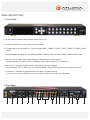
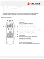
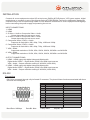
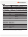
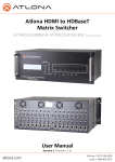
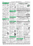
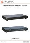
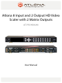
Atlona 8 Input and 2 Output HD Video
Scaler with 2 Matrix Outputs
AT-PROHD82M
User Manual
TABLE OF CONTENTS
1. Introduction
..................................................
3
2. Package Contents
..................................................
3
3. Features
..................................................
4
4. Applications
..................................................
4
5. Specification
..................................................
4
6.1. Front Panel
..................................................
5
6.2. Rear Panel
..................................................
5-6
7. Remote Control
..................................................
7
8. Installation
..................................................
8
9. RS 232
10. Safety Information
..................................................
..................................................
8-9
10
11. Warranty
..................................................
11
12. Atlona Product Registration
..................................................
12
6. Panel Description
INTRODUCTION
Atlona Technologies AT-PROHD82M has big switching power in a compact 1U size. AT-PROHD82M is a MultiVideo Matrix Switcher featuring 8 inputs and 2 outputs; each having both HDMI and VGA connections. Both
outputs are matrix and can display signals from any of the 8 inputs. This allows you to send audio and video
signals across multiple displays and is great for multi-room applications. Be able to display a presentation from
a computer on one display while video conferencing with a client on another at the same time; the possibilities
and applications are endless. The AT-PROHD82M scales the outgoing video signal on both the HDMI and VGA
outputs. The HDMI outputs are capable of displaying 720p and 1080p. The VGA outputs can display resolutions
from SVGA 800x600 to WUXGA 1920x1200. The AT-PROHD82M is also an auto signal sensing switcher. Once
a new device powers on, the AT-PROHD82M will automatically select that source and display it on the selected
output device. It will also take the analog stereo audio from any of the inputs and send it out on the HDMI outputs.
Take control with the On Screen Display, audio volume adjustment for each input, front IR receiver, two rear IR
extensions, RS-232 and RS-485 for third party control systems.
The 8 inputs include:
2 x Composite Video/S-Video + Stereo Audio
2 x Component Video + Stereo Audio
2 x VGA + Stereo Audio
2 x HDMI
The 2 matrix include:
2 x VGA + Stereo Audio
2 x Digital Audio S/PDIF
2 x HDMI
The AT-PROHD82M will automatically detect incoming TV signals in these formats:
NTSC 3.58, NTSC-EIAJ, NTSC 4.43
PAL, PALM, PAL-N, PAL-COMB-N, PAL-60
SECAM
The AT-PROHD82M HDMI inputs support all resolutions: 480i/p, 720p or 1080i/p.
PC resolutions up to 1920x1200 are ideal for high resolution projectors, LCD and Plasma televisions and other
HDTV applications.
Controlling the AT-PROHD82M is provided by front panel buttons with LED indicators, supplied IR remote control or RS-232. The RS-232 connection is designed to interface with third party control systems and programs.
PACKAGE CONTENTS
• Atlona Technologies AT-PROHD82M multi source HD video scaler with matrix outputs
• IR Remote Control
• 12V DC/3A Universal Power supply 110/240 V
• Instruction Manual
• RS-232 cable
• 19” rack ears
FEATURES
• The AT-PROHD82M is an 8 input and 2 output matrix switcher and scaler
• Any of the 8 inputs with stereo audio can simultaneously route to any output; and the same input can route to
all outputs or any other combination
• Multi-Video input signals include 2 x Composite, 2 x S-Video, 2 x Component, 2 x VGA and 2 x HDMI
• Composite, S-Video, Component and VGA are paired with stereo audio inputs
• Outputs include 2 x VGA + Stereo Audio and 2 x HDMI
• Signal sensing across all inputs automatically detects and changes input
• Direct video input selection by front panel buttons with LED readout
• Direct VGA output resolution selection. VGA resolution up to 1920x1200
• Stereo Audio volume adjustment on front panel
• OSD (On Screen Display) for menu, color, resolution and input source selection
• HDMI and HDCP compliant
• Supports RS-232 interface control driver software and third party control systems
• IR transceiver on front panel for IR remote control (included). External IR port on the rear panel supports
extended distances up to 1,000 ft.
• 19” rack mount included, 1U unit height
APPLICATIONS
Drive 2 HDMI enabled HDTV’s and/or 2 displays via VGA with high resolution video and stereo audio from up
to 8 different sources and scale each signal up to 1080p or 1920x1200.
SPECIFICATIONS
Video Scaling Outputs
Video
Input
Signals*
2x HDMI (Additional S/PDIF Digital Audio Output for each)
2x VGA via HD-15 Female connector (Audio: 2x 3.5mm connectors)
TV Standards
NTSC-M 3.58, NTSC-J 4.43, PAL-B-D-I-G-H-K, PAL-M, PAL-N COMB-N, SECAM (Impedance 75 ohms)
Composite Video
2x RCA connectors
S-Video (Y/C)
2x 4 pin Mini-Din Female connectors
Component Video
(YPrPb)
2x (3x RCA connectors)
PC-VGA (RGBHV)
2x HD-15 Female connectors
HDMI
Digital Video, Digital Audio (PCM), 2x HDMI connectors
Input sources
1 & 2 HDMI, 3 & 4 AV, 5 & 6 Component Video/Audio, 7 & 8 VGA
VGA output resolutions
SVGA, XGA, SXGA, WXGA, WSGA+, WUXGA
Video bandwidth
400MHz, (-3 dB)
Audio bandwidth
60MHz, (-3 dB)
Audio Frequency Response
20Hz~20KHz
Safety Approvals
CE, FCC and RoHS (2002/95/EC)
Dimensions (LWH)
19” x 7.87” x 1.75” (482mm x 200mm x 44mm), 1U height
Power Supply
12V DC/3A
* Composite, S-Video and Component inputs paired with analog audio input (RCA)
VGA inputs paired with analog audio input (3.5mm)
PANEL DESCRIPTIONS
1. Front Panel
1) Power selector allows user to switch power ON or OFF
2) Hold the “Enter” key for 5 seconds to activate OSD.
3) Change inputs for the output # 1. Cycle through HDMI 1, HDMI 2, CVSV1, CVSV2, COMP1, COMP2, VGA1,
VGA2
4) Change inputs for the output # 2. Cycle through HDMI 1, HDMI 2, CVSV1, CVSV2, COMP1, COMP2, VGA1, VGA2
5) Select “Left” or “Right” key to switch between adjustments for each output.
When switching, you will see this “I” character next to either output # 1 or output #2.
6) Once the “I” character is placed next to the output you want to adjust,
you can press “UP” or “Down” key to select resolutions. Select “Enter” to confirm the output resolution.
7) Once the “I” character is placed next to the output you want to adjust,
you can press Volume Up/Down keys to select the volume level for the specific output.
2. Rear Panel
1
2
3
4
5
6
7
8
9
10
11
12
13 14
15
16
1) DIGITAL AUDIO OUTPUTS
Digital audio output for both Output-1 and Output-2 with RCA connector is provided for each destination output.
These signals correspond to the HDMI outputs for Output-1 and Output-2 only.
2) HDMI OUTPUTS
Separate HDMI ports for Output-1 and Output-2 are provided for each output destination. These will carry signals converted from Composite/S-Video, Component (YPbPr), VGA and HDMI.
3) STEREO AUDIO OUTPUTS
Stereo audio output for both Output-1 and Output-2 with 3.5mm port is provided for each destination output.
These signals correspond to the VGA outputs for Output-1 and Output-2 only.
4) VGA OUTPUTS
Separate VGA (RGBHV) ports for Output-1 and Output-2 with 2x HD-15F female connectors are provided for
each output destination. These will carry signals converted from Composite/S-Video, Component (YPbPr),
VGA and HDMI.
5) INPUT 7 & 8 AUDIO INPUTS
Input 7 is a stereo analog audio RCA connector (AR/AL*) for Input 7 VGA.
Input 8 is a stereo analog audio RCA connector (AR/AL*) for Input 8 VGA.
* Analog Right/Analog Left
6) INPUT 7 & 8 VGA INPUTS
Both Input 7 and Input 8 is a VGA (RGBHV) input with HD-15P connector.
7) INPUT 5 & 6 AUDIO INPUTS
Input 5 is a stereo analog audio RCA connector (AR/AL) for Input 5 Component video.
Input 6 is a stereo analog audio RCA connector (AR/AL) for Input 6 Component video.
8) INPUT 5 & 6 COMPONENT VIDEO INPUTS
Both Input 5 and Input 6 is a Component (YPbPR) input with RCA connectors.
9) INPUT 3 & 4 AUDIO INPUTS
Input 3 is a stereo analog audio RCA connector (AR/AL) for Input 3 Composite or S-Video.
Input 4 is a stereo analog audio RCA connector (AR/AL) for Input 4 Composite or S-Video.
10) INPUT 3 & 4 COMPOSITE INPUTS
Both Input 3 and Input 4 is a Composite Video input with RCA connector.
11) INPUT 3 & 4 S-VIDEO INPUTS
Both Input 3 and Input 4 is a S-Video (Y/C) input with 4 pin Mini-Din connector.
12) INPUT 1 & 2 HDMI INPUTS
Both Input 1 and Input 2 is a HDMI (Digital) input that is HDCP compliant.
13) RS-485 CONTROL
RS-485 control port to allow for interfacing to a PC or third party control system.
14) RS-232 CONTROL
RS-232 control port to allow for interfacing to a PC or third party control system.
15) IR EXTENDER CONTROL
Separate IR Extender ports for Output-1 and Output-2.
IR EXT. 1 is for Output-1
IR EXT. 2 is for Output-2
16) DC POWER INLET
polarity. 12V DC power supply 3A Max.
Before making any connections to the AT-PROHD82M, observe the following:
• Ensure the main voltage supply matches the label on the supplied power plug (+/- 10%)
• Ensure that the power switch is OFF
• Ensure that all system grounds are connected to a common point
• Connect all audio/video sources and destination equipment
• Power up all source and destination audio/video sources
• For each destination output, select the appropriate input source by using the front panel input 1-8 select
buttons, the supplied IR remote control or through the RS-232/RS-485 serial communications port
• Upon power up, the AT-PROHD82M will return to its last used setting before powering down
REMOTE CONTROL
1) POWER ON
Turns unit ON with discrete command
2) POWER OFF
Turns unit OFF with discrete command
3) OUTPUT-1 RESLUTION SET / OSD
Setup the Output-1 resolutions or manual OSD
4) OUTPUT-2 RESOLUTION SET / OSD
Setup the Output-2 resolutions or manual OSD
5) SELECT VGA OUTPUT RESOLUTIONS
Select VGA output resolutions as following: SVGA 800x600,
XGA 1024x768, SXGA 1280x1024, WXGA 1366x768, WSXGA+
1680x1050, MAX WUXGA 1920x1200
6) SELECT HDMI OUTPUT RESOLUTIONS
Select HDMI output resolutions as 720p or 1080p
7) MANUAL OSD
OSD navigation buttons to setup or adjust settings
8) AUDIO VALUE ADJUSTMENT
Volume Up and Down adjustment
9) SELECT OUTPUT-1 SOURCES
Inputs 1-8 source selections to be displayed from Output-1
10) SELECT OUTPUT-2 SOURCES
Inputs 1-8 source selections to be displayed from Output-2
INSTALLATION
Connect all source equipment such as HD set top boxes, BluRay & DVD players, VCR, game system, digital
media player or computer to any of the 8 inputs on the AT-PROHD82M. Connect the destination displays/tel
evisions to any of the 2 outputs using HDMI or VGA. Make all connections to source equipment and displays
before connecting the power supply and powering the unit on.
INPUT CONNECTIONS
1. HDMI
2. HDMI
3. S-Video + Audio or Composite Video + Audio
Output dependent on last source used
4. S-Video + Audio or Composite Video + Audio
Output dependent on last source used
5. Component Video (YPbPr) + Audio
Supports all resolutions: 480i, 480p, 720p, 1080i and 1080p
6. Component Video (YPbPr) + Audio
Supports all resolutions: 480i, 480p, 720p, 1080i and 1080p
7. VGA + Audio
Supported resolutions: SVGA, XGA, SXGA, WXGA, WSXGA+ and WUXGA
8. VGA + Audio
Supported resolutions: SVGA, XGA, SXGA, WXGA, WSXGA+ and WUXGA
OUTPUT CONNECTIONS
1. HDMI – HDMI output with digital video and digital audio
Digital Audio S/PDIF – Digital Audio (PCM) from HDMI input sources
VGA + Audio – Output resolution scaling to WUXGA (1920x1200)
2. HDMI – HDMI output with digital video and digital audio
Digital Audio S/PDIF – Digital Audio (PCM) from HDMI input sources
VGA + Audio – Output resolution scaling to WUXGA (1920x1200)
RS-232
Connection
RS-232 is connected through a 9-pin female D connector. The pins will have functions associated with them
some will be unassigned.
5 4 3 2 1
9 8 7 6
Baud Rate: 9600bps
Data Bit: 8bits
No.
Pin
Function
1
----
Not used
2
Tx
Transmit
3
Rx
Receive
4
----
Not used
5
Gnd
Ground
6
----
Not used
7
----
Not used
8
----
Not used
9
----
Not used
Parity: None
Stop Bit: 1bit
Command
System Command Codes
Functions
/*Type;
Brings up the model information
/%Lock;
Locks the front panel of the Matrix switcher
/%Unlock;
Unlocks the front panel of the Matrix switcher
/^Version;
The command codes are very sensitive, do not change capitalization, spacing, or lettering.
Command
PWON
PWOFF
All#
x1$
x1AVx2
x1AVx2,x3,x4
Statusx1
Status
Save[Y]
Recall[Y]
Volume100, Volume101,
Volume102, Volume103,
Volume104, Volume105,
Volume106, Volume107,
Volume108, Volume109,
Volume110
Volume200, Volume201,
Volume202, Volume203,
Volume204, Volume205,
Volume206, Volume207,
Volume208, Volume209,
Volume210
Clear[Y]
Mreset
Feedback
PWON
PWOFF
All#
Description
Power on
Power off
Resets all inputs to corresponding outputs (in3 to
out3)
x1$
Turns off output channel (to turn off output 3 = x3$)
x1AVx2
Switch input to output (input 3 to output 5 =
x3AVx5)
x1AVx2,x3,x4
Switch input to multiple outputs (input 3 =
x3AVx1,x2)
x7AVx1
Shows what input is connected to selected output
x1AVx1, x2AVx2,
Displays which inputs are currently connected to
x3AVx4, ....
which outputs
Save2
Saves settings for future use, saves vary from 0 to
9
Recall2
Pulls up saved settings for the number you selected
Volume100, Volume101, Adjusts the volume on output 1
Volume102, Volume103,
Volume104, Volume105,
Volume106, Volume107,
Volume108, Volume109,
Volume110
Volume200, Volume201, Adjusts the volume on output 2
Volume202, Volume203,
Volume204, Volume205,
Volume206, Volume207,
Volume208, Volume209,
Volume210
Clear2
Erases the save for the number you selected
Mreset
Sets matrix back to the default settings
Each command or feedback is terminated with a carriage return.
Note: If the command fails or is incorrect the feedback should be “Command FAILED”
Safety Information
Safeguards
To reduce the risk of electric shock,
do not expose this product to rain or
moisture
local power socket, hire an electrician
to replace your obsolete socket.
Do not modify the wall plug. Doing
so will void the warranty and safety
features.
This equipment should be installed
near the socket outlet and the device
should be easily accessible in the case
it requires disconnection.
Precautions
not expressly approved by the manufacturer, could void the user’s authority to operate this
equipment.
Operate this product using only the included external power supply. Use of other power supplies
In the event of an electrostatic discharge this device may automatically turn off. If this occurs,
unplug the device and plug it back in.
Protect and route power cords so they will not be stepped on or pinched by anything placed on
or against them. Be especially careful of plug-ins or cord exit points from this product.
Avoid excessive humidity, sudden temperature changes or temperature extremes.
Keep this product away from wet locations such as bathtubs, sinks, laundries, wet basements,
Unplug the product before cleaning. Use a damp cloth for cleaning and not
Never open, remove unit panels, or make any adjustments not described in this manual.
Attempting to do so could expose you to dangerous electrical shock or other hazards. It may
also cause damage to your AT-HDView. Opening the product will void the warranty.
Do not attempt to service the unit. Disconnect the product and contact your authorized Atlona
reseller or contact Atlona directly.
Warranty
Limited Warranty
Atlona Technologies warrants that (a) its products (the AT-HD-V12x2 or
AT-HD-V16x2) will perform substantially in accordance with the accompanying written
materials for a period of 3 years from the date of receipt and (b) that the product will
be free from defects in materials and workmanship under normal use and service for
a period of 3 years. In the event applicable law imposes any implied warranties, the
implied warranty period is limited to 3 years from the date of receipt. Some jurisdictions
do not allow such limitations on duration of an implied warranty, so the above limitation
may not apply to customers that fall within those areas.
Customer Remedies
Atlona Technologies’ and its suppliers’ entire liability and Customer’s exclusive
remedy shall be, at Atlona Technologies’ decision, either return of the price paid for the
product, repair, or replacement of the product that does not meet this Limited Warranty
and which is returned to Atlona Technologies with a copy of the Customer’s receipt.
This Limited Warranty is void if failure of the product has resulted from accident, abuse,
misapplication, or natural occurrence. In example but not limited to: power surges
(electrical storms, local power outage), dropping the product (or items on the product),
Any replacement
product will be warranted for the remainder of the original warranty period.
No other warranties
To the maximum extent permitted by applicable law, Atlona Technologies and its
suppliers disclaim all other warranties, either expressed or implied, including, but not
with regard to the product and any related written materials. This Limited Warranty
jurisdiction.
No liability for damages
To the maximum extent permitted by applicable law, in no event shall Atlona
Technologies or its suppliers be liable for any damages arising out of the use of or
inability to use this product, even if Atlona Technologies has been advised of the
possibility of such damages. Such damages include but are not limited to: special,
incidental, consequential, or indirect damages for personal injury, loss of business
loss. Atlona Technologies’ and its suppliers’ entire liability under any provision of this
agreement shall be limited to the amount actually paid by you for the product. Some
Jurisdictions do not allow the exclusion or limitation of liability for consequential or
incidental damage. The above limitations may not apply to you in such jurisdictional
cases.
Atlona Product Registration
Thank you for purchasing this Atlona product. - We hope you enjoy it and will take an
extra few moments to register your new purchase.
Registration creates an ownership record if your product is lost or stolen and helps
At Atlona, we respect and protect your privacy, assuring you that your registration
information is completely secure. Atlona product registration is completely voluntary and
failure to register will not diminish your limited warranty rights.