1
Satellite P200/Satellite Pro P200
TOSHIBA
Satellite P200/
Satellite Pro P200 Series
User's Manual
Copyright
© 2007 by TOSHIBA Corporation. All rights reserved. Under copyright law,
this manual cannot be reproduced in any form without the prior written
permission of TOSHIBA. No patent liability is assumed, with respect to the
use of the information contained herein.
TOSHIBA Satellite P200/Satellite Pro P200 Series Portable Personal
Computer User's Manual
First edition March 2007
Ownership and copyright of music, video computer programs, databases,
etc. are protected by the copyright laws. These copyrighted materials may
be copied for private use at home only. If, beyond the limitation above, you
copy (including to transform data formats) or modify these materials,
transfer them or distribute them via the Internet without approval of
copyright owners, you may be subject to claims for compensation for
damage and/or criminal penalties due to infringements of copyrights or
personal rights. Please remember to observe the copyright laws when you
use this product to copy the copyrighted works or perform other actions.
Please note that you may infringe the owner's rights protected by the
copyright laws if you use the screen mode switching functions (e.g. Wide
mode, Wide Zoom mode, etc.) of this product to display enlarged images/
video at coffee shops or hotels for the purposes of profits or providing these
to the public.
Disclaimer
This manual has been validated and reviewed for accuracy. The instructions
and descriptions it contains are accurate for the Satellite P200/Satellite Pro
P200 Series Portable Personal Computers at the time of this manual’s
production. However, succeeding computers and manuals are subject to
change without notice. TOSHIBA assumes no liability for damages incurred
directly or indirectly from errors, omissions or discrepancies between the
computer and the manual.
Trademarks
IBM is a registered trademark and IBM PC, OS/2, and PS/2 are trademarks
of International Business Machines Corporation.
Celeron, Intel, Intel SpeedStep, Pentium, Intel Core and Centrino are
trademarks or registered trademarks of Intel Corporation or its subsidiaries
in the United States and other countries.
MS-DOS, Microsoft, Windows and DirectX are registered trademarks and
Microsoft Vista is a Trademark of Microsoft Corporation.
Centronics is a registered trademark of Centronics Data Computer
Corporation. Photo CD is a trademark of Eastman Kodak.
Bluetooth is a trademark owned by its proprietor and used by TOSHIBA
under license.
ii
Satellite P200/Satellite Pro P200
iLINK is a trademark of Sony Corporation.
Other trademarks and registered trademarks not listed above may be used
in this manual.
Macrovision License of Notice
This product incorporates copyright protection technology that is protected
by U.S. patents and other intellectual property rights. Use of this copyright
protection technology must be authorized by Macrovision, and is intended
for home and other limited viewing uses only unless otherwise authorized
by Macrovision. Reverse engineering or disassembly is prohibited.
Safety Instructions
Use the following safety guidelines to help protect yourself and your
computer.
When Using Your Computer
Do not operate your portable computer for an extended period of time with
the base resting directly on your body. With extended operation, heat can
potentially build up in the base. Allowing sustained contact with the skin
could cause discomfort or, eventually, a burn.
■ Do not attempt to service the computer yourself. Always follow
installation instructions closely.
■ Do not carry a battery in your pocket, purse, or other container where
metal objects (such as car keys) could short-circuit the battery terminals.
The resulting excessive current follow can cause extremely high
temperatures and may result in damage from burns.
■ Be sure that nothing rests on your AC adapter's power cable and that
the cable is not located where it can be tripped over or stepped on.
■ Place the AC adapter in a ventilated area, such as a desk top or on the
floor, when you use it to run the computer or to charge the battery. Do
not cover the AC adapter with papers or other items that will reduce
cooling; also, do not use the AC adapter while it is inside a carrying case.
■ Use only the AC adapter and batteries that are approved for use with
this computer. Use of another type of battery or AC adapter may risk fire
or explosion.
Satellite P200/Satellite Pro P200
iii
■ Before you connect the computer to a power source, ensure that the
voltage rating of the AC adapter matches that of the available power
source.
115V/60Hz in most of North and South America and some Far Eastern
countries such as Taiwan.
100 V/50Hz in eastern Japan and 100 V/60Hz in western Japan.
230 V/50 Hz in most of Europe, the Middle East, and the Far East.
■ If you use an extension cable with your AC adapter, ensure that the total
ampere rating of the products that are plugged into it do not exceed the
ampere rating of the extension cable itself.
■ To help avoid the potential hazard of electric shock, do not connect or
disconnect any cables or perform maintenance or reconfiguration of this
product during an electrical storm.
■ When setting up the computer for work, place it on a level surface.
■ Do not dispose of batteries in a fire. They may explode. Check with local
authorities for disposal instructions.
■ When travelling, do not check the computer as baggage. You can put
your computer through an X-ray security machine, but never put your
computer through a metal detector. If you have the computer checked
by hand, be sure to have a charged battery available in case you are
asked to turn on the computer.
■ When travelling with the hard drive removed from the computer, wrap
the drive in a non-conducting material, such as cloth or paper. If you
have the drive checked by hand, be ready to install the drive in the
computer. Your can put the hard drive through an X-ray security
machine, but never put it through a metal detector.
■ When travelling, do not place the computer in overhead storage
compartments where it could slide around. Do not drop your computer
or subject it to other mechanical shocks.
■ Protect your computer, battery, and hard drive from environmental
hazards such as dirt, dust, food, liquids, temperature extremes, and
overexposure to sunlight.
■ When you move your computer between environments with very
different temperature and/or humidity ranges, condensation may form
on or within the computer. To avoid damaging the computer, allow
sufficient time for the moisture to evaporate before using the computer.
■ When you disconnect a cable, pull on its connector or on its strain relief
loop, not on the cable itself. As you pull out the connector, keep it evenly
aligned to avoid bending any connector pins. Also, before you connect
a cable make sure both connectors are correctly oriented and aligned.
■ Before you clean your computer, turn if off, unplug it from its power
source, and remove the battery.
■ Handle components with care. Hold a component such as a memory
module by its edges, not its pins.
iv
Satellite P200/Satellite Pro P200
When using telephone equipment in conjunction with your computer, basic
safety precautions should always be followed to reduce the risk of fire,
electric shock and injury to persons, including the following:
■ Do not use this product near water, for example, near a bathtub, washing
bowl, kitchen sink or laundry tub, in a wet basement or near a swimming
pool.
■ Avoid using a telephone (other than a cordless type) during an electrical
storm. There may be a remote risk of electric shock from lightning.
■ Do not use the telephone to report a gas leak in the vicinity of the leak.
■ Use only the power cord indicated in this manual.
■ Replace only with the same or equivalent type battery recommended by
the manufacturer.
■ Dispose of used batteries according to the manufacturer's instructions.
■ To reduce the risk of fire, use only No. 26 AWG or larger
telecommunication line cord.
Use only the battery pack that came with the computer or an optional
battery pack. Use of the wrong battery could damage your computer.
TOSHIBA assumes no liability for any damage in such case.
FCC information
Model Name: Satellite P200/Satellite Pro P200 Series
FCC notice "Declaration of Conformity Information"
This equipment has been tested and found to comply with the limits for a
Class B digital device, pursuant to part 15 of the FCC rules. These limits are
designed to provide reasonable protection against harmful interference in
a residential installation.
This equipment generates, uses and can radiate radio frequency energy
and, if not installed and used in accordance with the instructions, may cause
harmful interference to radio communications. However, there is no
guarantee that interference will not occur in a particular installation. If this
equipment does cause harmful interference to radio or television reception,
which can be determined by turning the equipment off and on, the user is
encouraged to try to correct the interference by one or more of the following
measures:
■ Reorient or relocate the receiving antenna.
■ Increase the separation between the equipment and receiver.
■ Connect the equipment into an outlet on a circuit different from that to
which the receiver is connected.
■ Consult the dealer or an experienced radio/TV technician for help.
Satellite P200/Satellite Pro P200
v
Only peripherals complying with the FCC class B limits may be attached to
this equipment. Operation with non-compliant peripherals or peripherals
not recommended by TOSHIBA is likely to result in interference to radio
and TV reception. Shielded cables must be used between the external
devices and the computer's or expansion unit's external monitor port,
parallel port, USB port and microphone jack. Changes or modifications
made to this equipment, not expressly approved by TOSHIBA or parties
authorized by TOSHIBA could void the user's authority to operate the
equipment.
EMC Regulatory Information
Contact
Address:
TOSHIBA America Information Systems, Inc.
9740 Irvine Boulevard
Irvine, California 92618-1697
Telephone:
(949) 583-3000
EU Declaration of Conformity
TOSHIBA declares, that the product: Satellite P200/Satellite Pro P200
Series conforms to the following Standards:
This product is labelled with the CE Mark in accordance with the related
European Directives, notably Electromagnetic Compatibility Directive 89/
336/EEC for the notebook and the electronic accessories including the
supplied power adapter, the Radio Equipment and Telecommunications
Terminal Equipment Directive 99/5/EEC in case of implemented
telecommunication accessories and the Low Voltage Directive 73/23/EEC
for the supplied power adapter.
CE Marking is the responsibility of TOSHIBA EUROPE GmbH,
Hammfelddamm 8, 41460 Neuss, Germany, phone +49-(0)-2131-158-01.
For a copy of the related CE Declaration of Conformity please refer to the
following website: http://epps.toshiba-teg.com.
vi
Satellite P200/Satellite Pro P200
Canadian Regulatory Information (Canada Only)
This digital apparatus does not exceed the Class B limits for radio noise
emissions from digital apparatus as set out in the Radio Interference
Regulation of the Canadian Department of Communications.
Note that Canadian Department of Communications (DOC) regulations
provide, that changes or modifications not expressly approved by TOSHIBA
Corporation could void your authority to operate this equipment.
This Class B digital apparatus meets all requirements of the Canadian
Interference-Causing Equipment Regulations.
Cet appareil numérique de la class B respecte toutes les exgences du
Règlement sur le matériel brouilleur du Canada.
BSMI Notice (Taiwan Only)
Following information is only for EU-member states:
The symbol indicates that this product may not be treated as
household waste. Please ensure this product is properly
disposed as inappropriate waste handling of this product may
cause potential hazards to the environment and human health.
For more detailed information about recycling of this product,
please contact your local city office, your household waste
disposal service or the shop where you purchased the product.
This symbol may not stick depending on the country and region where you
purchased.
Satellite P200/Satellite Pro P200
vii
Optical Disc Drive Safety Instruction
■ Be sure to check the international precautions at the end of this section.
The optical drive that is used in this computer is equipped with a laser
device. A classification label with the following sentence is affixed to the
surface of the drive.
CLASS 1 LASER PRODUCT
LASER KLASSE 1
LUOKAN 1 LASERLAITE
APPAREIL A LASER DE CLASSE 1
KLASS 1 LASER APPARAT
The drive with the above label is certified by the manufacturer that the drive
complies with the requirement for laser product on the date of
manufacturing pursuant to article 21 of Code of Federal Regulations by the
United States of America, Department of Health & Human Services, Food
and Drug Administration.
In other countries, the drive is certified to comply with the requirement
pursant to IEC 825 and EN60825 on class 1 laser product.
This computer is equipped with one of the optical drive in the following list
according to the model.
viii
Satellite P200/Satellite Pro P200
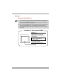
TOSHIBA Samsung Storage Technology
CD-RW/DVD-ROM TS-L462D
■ The CD-RW/DVD-ROM drive employs a laser system. To ensure proper
use of this product, please read this instruction manual carefully and
retain for future reference. Should the unit ever require maintenance,
contact an authorized service location.
■ Use of controls, adjustments or the performance of procedures other
than those specified may result in hazardous radiation exposure.
■ To prevent direct exposure to the laser beam, do not try to open the
enclosure.
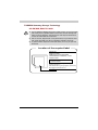
Location of the required label
SERIAL NO.
MANUFACTURED:
COMPLIES WITH FDA RADIATION
PERFORMANCE STANDARDS, 21 CFR
SUBCHAPTER J.
CLASS 1 LASER PRODUCT
LASER KLASSE 1
TOSHIBA Samsung Storage Technology
Korea Corporation
416, Maetan-3Dong, Yeongtong-Gu, Suwon City,
Gyeonggi-Do, 443-742, Korea
Satellite P200/Satellite Pro P200
ix
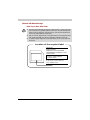
TEAC
CD-RW/DVD-ROM DW-224E
■ The CD-RW/DVD-ROM drive employs a laser system. To ensure proper
use of this product, please read this instruction manual carefully and
retain for future reference. Should the unit ever require maintenance,
contact an authorized service location.
■ Use of controls, adjustments or the performance of procedures other
than those specified may result in hazardous radiation exposure.
■ To prevent direct exposure to the laser beam, do not try to open the
enclosure.
Location of the required label
SERIAL NO.
MANUFACTURED:
COMPLIES WITH FDA RADIATION
PERFORMANCE STANDARDS, 21 CFR
SUBCHAPTER J.
CLASS 1 LASER PRODUCT
LASER KLASSE 1
TEAC CORPORATION
3-7-3 NAKA-CHO, MUSASHINO-SHI
TOKYO, JAPAN
x
Satellite P200/Satellite Pro P200
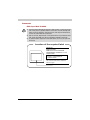
Pioneer
DVD Super Multi DVR-K17
■ The DVD Super Multi drive employs a laser system. To ensure proper
use of this product, please read this instruction manual carefully and
retain for future reference. Should the unit ever require maintenance,
contact an authorized service location.
■ Use of controls, adjustments or the performance of procedures other
than those specified may result in hazardous radiation exposure.
■ To prevent direct exposure to the laser beam, do not try to open the
enclosure.
Location of the required label
SERIAL NO.
MANUFACTURED:
COMPLIES WITH FDA RADIATION
PERFORMANCE STANDARDS, 21 CFR
SUBCHAPTER J.
CLASS 1 LASER PRODUCT
LASER KLASSE 1
PIONEER CORPORATION
4-1, MEGURO 1-CHOME
MEGURO-KU, TOKYO, 153-8654
Satellite P200/Satellite Pro P200
xi
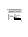
TOSHIBA Samsung Storage Technology
TS-L632D
■ The drive employs a laser system. To ensure proper use of this product,
please read this instruction manual carefully and retain for future
reference. Should the unit ever require maintenance, contact an
authorized service location.
■ Use of controls, adjustments or the performance of procedures other
than those specified may result in hazardous radiation exposure.
■ To prevent direct exposure to the laser beam, do not try to open the
enclosure.
Location of the required label
SERIAL NO.
MANUFACTURED:
COMPLIES WITH FDA RADIATION
PERFORMANCE STANDARDS, 21 CFR
SUBCHAPTER J.
CLASS 1 LASER PRODUCT
LASER KLASSE 1
TOSHIBA Samsung Storage Technology
Korea Corporation
416, Maetan-3Dong, Yeongtong-Gu, Suwon City,
Gyeonggi-Do, 443-742, Korea
xii
Satellite P200/Satellite Pro P200
Hitachi-LG Data Storage
DVD Super Multi GSA-T20N
■ The DVD Super Multi drive employs a laser system. To ensure proper
use of this product, please read this instruction manual carefully and
retain for future reference. Should the unit ever require maintenance,
contact an authorized service location.
■ Use of controls, adjustments or the performance of procedures other
than those specified may result in hazardous radiation exposure.
■ To prevent direct exposure to the laser beam, do not try to open the
enclosure.
Location of the required label
SERIAL NO.
MANUFACTURED:
COMPLIES WITH FDA RADIATION
PERFORMANCE STANDARDS, 21 CFR
SUBCHAPTER J.
CLASS 1 LASER PRODUCT
LASER KLASSE 1
Hitachi-LG Data Storage, Inc.
22-23, Kaigan 3-chome, Minato-ku,
Yokyo, 108-0022 Japan
Satellite P200/Satellite Pro P200
xiii
Panasonic
DVD Super Multi UJ-850U
■ The DVD Super Multi drive employs a laser system. To ensure proper
use of this product, please read this instruction manual carefully and
retain for future reference. Should the unit ever require maintenance,
contact an authorized service location.
■ Use of controls, adjustments or the performance of procedures other
than those specified may result in hazardous radiation exposure.
■ To prevent direct exposure to the laser beam, do not try to open the
enclosure.
Location of the required label
SERIAL NO.
MANUFACTURED:
COMPLIES WITH FDA RADIATION
PERFORMANCE STANDARDS, 21 CFR
SUBCHAPTER J.
CLASS 1 LASER PRODUCT
LASER KLASSE 1
Panasonic Communications Co., Ltd.
1-62, 4-Chome Minoshima, Hakata-Ku
Fukuoka, Japan
xiv
Satellite P200/Satellite Pro P200
TEAC
DV-W28EC
■ The drive employs a laser system. To ensure proper use of this product,
please read this instruction manual carefully and retain for future
reference. Should the unit ever require maintenance, contact an
authorized service location.
■ Use of controls, adjustments or the performance of procedures other
than those specified may result in hazardous radiation exposure.
■ To prevent direct exposure to the laser beam, do not try to open the
enclosure.
Location of the required label
SERIAL NO.
MANUFACTURED:
COMPLIES WITH FDA RADIATION
PERFORMANCE STANDARDS, 21 CFR
SUBCHAPTER J.
CLASS 1 LASER PRODUCT
LASER KLASSE 1
TEAC CORPORATION
3-7-3 NAKA-CHO, MUSASHINO-SHI
TOKYO, JAPAN
Satellite P200/Satellite Pro P200
xv
International Precautions
CAUTION: This appliance contains a laser system
and is classified as a "CLASS 1 LASER
PRODUCT." To use this model properly, read the
instruction manual carefully and keep this manual
for your future reference. In case of any trouble
with this model, please contact your nearest
"AUTHORIZED service station." To prevent direct
exposure to the laser beam, do not try to open the
enclosure.
VORSICHT: Dieses Gerät enthält ein LaserSystem und ist als "LASERSCHUTZKLASSE 1
PRODUKT" klassifiziert. Für den richtigen
Gebrauch dieses Modells lesen Sie bitte die
Bedienungsanleitung sorgfältig durch und
bewahren diese bitte als Referenz auf. Falls
Probleme mit diesem Modell auftreten,
benachrichtigen Sie bitte die nächste "autorisierte
Service-Vertretung". Um einen direkten Kontakt
mit dem Laserstrahl zu vermeiden darf das Gerät
nicht geöffnet werden.
ADVARSEL: Denne mærking er anbragt udvendigt
på apparatet og indikerer, at apparatet arbejder
med laserstråler af klasse 1, hviket betyder, at der
anvendes laserstrlier af svageste klasse, og at
man ikke på apparatets yderside kan bilve udsat
for utilladellg kraftig stråling.
APPARATET BOR KUN ÅBNES AF FAGFOLK
MED SÆRLIGT KENDSKAB TIL APPARATER
MED LASERSTRÅLER!
Indvendigt i apparatet er anbragt den her gengivne
advarselsmækning, som advarer imod at foretage
sådanne indgreb i apparatet, at man kan komme
til at udsætte sig for laserstråling.
OBS! Apparaten innehåller laserkomponent som
avger laserstråining överstigande gränsen för
laserklass 1.
VAROITUS. Suojakoteloa si saa avata. Laite
sisältää laserdiodin, joka lähetää näkymätöntä
silmilie vaarallista lasersäteilyä.
CAUTION: USE OF CONTROLS OR
ADJUSTMENTS OR PERFORMANCE OF
PROCEDURES OTHER THAN THOSE SPECIFIED
IN THE OWNER'S MANUAL MAY RESULT IN
HAZARDOUS RADIATION EXPOSURE.
xvi
Satellite P200/Satellite Pro P200
VORSICHT: DIE VERWENDUNG VON ANDEREN
STEURUNGEN ODER EINSTELLUNGEN ODER
DAS DURCHFÜHREN VON ANDEREN
VORGÄNGEN ALS IN DER
BEDIENUNGSANLEITUNG BESCHRIEBEN
KÖNNEN GEFÄHRLICHE
STRAHLENEXPOSITIONEN ZUR FOLGE HABEN.
Modem warning notice
Conformity Statement
The equipment has been approved to [Commission Decision "CTR21"] for
pan- European single terminal connection to the Public Switched Telephone
Network (PSTN).
However, due to differences between the individual PSTNs provided in
different countries/regions the approval does not, of itself, give an
unconditional assurance of successful operation on every PSTN network
termination point.
In the event of problems, you should contact your equipment supplier in the
first instance.
Network Compatibility Statement
This product is designed to work with, and is compatible with the following
networks. It has been tested to and found to confirm with the additional
requirements conditional in EG 201 121.
Germany
ATAAB AN005, AN006, AN007, AN009, AN010
and DE03, 04, 05, 08, 09, 12, 14, 17
Greece
ATAAB AN005, AN006 and GR01, 02, 03, 04
Portugal
ATAAB AN001, 005, 006, 007, 011 and P03, 04,
08, 10
Spain
ATAAB AN005, 007, 012, and ES01
Switzerland
ATAAB AN002
Norway
ATAAB AN002, 005, 007 and
NO 01, 02
All other countries/
regions
ATAAB AN003, 004
Specific switch settings or software setup are required for each network,
please refer to the relevant sections of the user guide for more details.
The hookflash (timed break register recall) function is subject to separate
national type approvals. It has not been tested for conformity to national
type regulations, and no guarantee of successful operation of that specific
function on specific national networks can be given.
Satellite P200/Satellite Pro P200
xvii
Japan regulations
Region selection
If you are using the computer in Japan, technical regulations described in
the Telecommunications Business Law require that you select the Japan
country mode.
It is illegal to use the modem in Japan with any other selection.
Redial
Up to two redial attempts can be made. If more than two redial attempts
are made, the modem will return Black Listed. If you are experiencing
problems with the Black Listed code, set the interval between redials at one
minute or longer.
Japan's Telecommunications Business Law permits up to two redials on
analogue telephones, but the redials must be made within a total of three
minutes.
The internal modem is approved by Japan Approvals Institute for
Telecommunications Equipment.
A05-0413001
Pursuant to FCC CFR 47, Part 68:
When you are ready to install or use the modem, call your local telephone
company and give them the following information:
■ The telephone number of the line to which you will connect the modem
■ The registration number that is located on the device
US: AGSMD01BDELPHI
The FCC registration number of the modem will be found on either the device
which is to be installed, or, if already installed, on the bottom of the computer
outside of the main system label.
■ The Ringer Equivalence Number (REN) of the modem, which can vary.
For the REN of your modem, refer to your computer's user's guide.
The modem connects to the telephone line by means of a standard jack
called the USOC RJ11C.
xviii
Satellite P200/Satellite Pro P200
Type of service
Your modem is designed to be used on standard-device telephone lines.
Connection to telephone company-provided coin service (central office
implemented systems) is prohibited. Connection to party lines service is
subject to state tariffs. If you have any questions about your telephone line,
such as how many pieces of equipment you can connect to it, the telephone
company will provide this information upon request.
Telephone company procedures
The goal of the telephone company is to provide you with the best service
it can. In order to do this, it may occasionally be necessary for them to make
changes in their equipment, operations, or procedures. If these changes
might affect your service or the operation of your equipment, the telephone
company will give you notice in writing to allow you to make any changes
necessary to maintain uninterrupted service.
If problems arise
If any of your telephone equipment is not operating properly, you should
immediately remove it from your telephone line, as it may cause harm to the
telephone network. If the telephone company notes a problem, they may
temporarily discontinue service. When practical, they will notify you in
advance of this disconnection.
If advance notice is not feasible, you will be notified as soon as possible.
When you are notified, you will be given the opportunity to correct the
problem and informed of your right to file a complaint with the FCC. In the
event repairs are ever needed on your modem, they should be performed
by TOSHIBA Corporation or an authorized representative of TOSHIBA
Corporation.
Disconnection
If you should ever decide to permanently disconnect your modem from its
present line, please call the telephone company and let them know of this
change.
Fax branding
The Telephone Consumer Protection Act of 1991 makes it unlawful for any
person to use a computer or other electronic device to send any message
via a telephone fax machine unless such message clearly contains in a
margin at the top or bottom of each transmitted page or on the first page
of the transmission, the date and time it is sent and an identification of the
business, other entity or individual sending the message and the telephone
number of the sending machine or such business, other entity or individual.
In order to program this information into your fax modem, you should
complete the setup of your fax software before sending messages.
Satellite P200/Satellite Pro P200
xix
Instructions for IC CS-03 certified equipment
1. NOTICE: The Industry Canada label identifies certified equipment. This
certification means that the equipment meets certain
telecommunications network protective, operational and safety
requirements as prescribed in the appropriate Terminal Equipment
Technical Requirements document(s). The Department does not
guarantee the equipment will operate to the user's satisfaction.
Before installing this equipment, users should ensure that it is
permissible to be connected to the facilities of the local
telecommunications company. The equipment must also be installed
using an acceptable method of connection.
The customer should be aware that compliance with the above
conditions may not prevent degradation of service in some situations.
Repairs to certified equipment should be coordinated by a
representative designated by the supplier. Any repairs or alterations
made by the user to this equipment, or equipment malfunctions, may
give the telecommunications company cause to request the user to
disconnect the equipment.
Users should ensure for their own protection that the electrical ground
connections of the power utility, telephone lines and internal metallic
water pipe system, if present, are connected together. This precaution
may be particularly important in rural areas.
Users should not attempt to make such connections themselves, but
should contact the appropriate electric inspection authority, or electrician,
as appropriate.
2. The user manual of analog equipment must contain the equipment's
Ringer Equivalence Number (REN) and an explanation notice similar to
the following: The Ringer Equivalence Number (REN) of the modem,
which can vary. For the REN of your modem, refer to your computer's
user's guide.
The Ringer Equivalence Number (REN) assigned to each terminal device
provides an indication of the maximum number of terminals allowed to be
connected to a telephone interface. The termination on an interface may
consist of any combination of devices subject only to the requirement that
the sum of the Ringer Equivalence Numbers of all the devices does not
exceed 5.
3. The standard connecting arrangement (telephone jack type) for this
equipment is jack type(s): USOC RJ11C.
The IC registration number of the modem is shown below.
Canada: 4005B-DELPHI
xx
Satellite P200/Satellite Pro P200
Notes for Users in Australia and New Zealand
Modem warning notice for Australia
Modems connected to the Australian telecoms network must have a valid
Austel permit. This modem has been specifically configured to ensure
compliance with Austel standards when the country/region selection is set
to Australia.
The use of other country/region setting while the modem is attached to the
Australian PSTN would result in your modem being operated in a noncompliant manner. To verify that the country/region is correctly set, enter
the command ATI which displays the currently active setting.
To set the country/region permanently to Australia, enter the following
command sequence:
■ AT%TE=1
■ ATS133=1
■ AT&F
■ AT&W
■ AT%TE=0
■ ATZ
Failure to set the modem to the Australia country/region setting as shown
above will result in the modem being operated in a non-compliant manner.
Consequently, there would be no permit in force for this equipment and the
Telecoms Act 1991 prescribes a penalty of $12,000 for the connection of
non-permitted equipment.
Notes for use of this device in New Zealand
■ The grant of a Telepermit for a device in no way indicates Telecom
acceptance of responsibility for the correct operation of that device
under all operating conditions. In particular the higher speeds at which
this modem is capable of operating depend on a specific network
implementation which is only one of many ways of delivering high quality
voice telephony to customers. Failure to operate should not be reported
as a fault to Telecom.
■ In addition to satisfactory line conditions a modem can only work
properly if:
a/ it is compatible with the modem at the other end of the call and
b/ the application using the modem is compatible with the application
at the other end of the call - e.g., accessing the Internet requires
suitable software in addition to a modem.
■ This equipment shall not be used in any manner which could constitute
a nuisance to other Telecom customers.
Satellite P200/Satellite Pro P200
xxi
■ Some parameters required for compliance with Telecom's PTC
Specifications are dependent on the equipment (PC) associated with
this modem. The associated equipment shall be set to operate within
the following limits for compliance with Telecom Specifications:
a/ There shall be no more than 10 call attempts to the same number
within any 30 minute period for any single manual call initiation, and
b/ The equipment shall go on-hook for a period of not less than 30
seconds between the end of one attempt and the beginning of the
next.
c/ Automatic calls to different numbers shall be not less than 5 seconds
apart.
■ Immediately disconnect this equipment should it become physically
damaged, and arrange for its disposal or repair.
■ The correct settings for use with this modem in New Zealand are as
follows:
ATB0 (CCITT operation)
AT&G2 (1800 Hz guard tone)
AT&P1 (Decadic dialling make-break ratio =33%/67%
ATS0=0 (not auto answer)
ATS10=less than 150 (loss of carrier to hangup delay, factory default of
15 recommended)
ATS11=90 (DTMF dealing on/off duration=90 ms)
ATX2 (Dial tone detect, but not (U.S.A.) call progress detect)
■ When used in the Auto Answer mode, the S0 register must be set with
a value of 3 or 4. This ensures:
(a) a person calling your modem will hear a short burst of ringing before
the modem answers. This confirms that the call has been
successfully switched through the network.
(b) caller identification information (which occurs between the first and
second ring cadences) is not destroyed.
■ The preferred method of dialling is to use DTMF tones (ATDT...) as this
is faster and more reliable than pulse (decadic) dialling. If for some
reason you must use decadic dealing, your communications program
must be set up to record numbers using the following translation table
as this modem does not implement the New Zealand "Reverse Dialling"
standard.
Number to be dialled: 0 1 2 3 4 5 6 7 8 9
Number to program into computer: 0 9 8 7 6 5 4 3 2 1
Note that where DTMF dealing is used, the numbers should be entered
normally.
■ The transmit level from this device is set at a fixed level and because of
this there may be circumstances where the performance is less than
optimal. Before reporting such occurrences as faults, please check the
line with a standard Telepermitted telephone, and only report a fault if
the phone performance is impaired.
xxii
Satellite P200/Satellite Pro P200
■ It is recommended that this equipment be disconnected from the
Telecom line during electrical storms.
■ When relocating the equipment, always disconnect the Telecom line
connection before the power connection, and reconnect the power first.
■ This equipment may not be compatible with Telecom Distinctive Alert
cadences and services such as FaxAbility.
( NOTE THAT FAULT CALL OUT CAUSED BY ANY OF THE ABOVE
CAUSES MAY INCUR A CHARGE FROM TELECOM )
General conditions
As required by PTC 100, please ensure that this office is advised of any
changes to the specifications of these products which might affect
compliance with the relevant PTC Specifications.
The grant of this Telepermit is specific to the above products with the
marketing description as stated on the Telepermit label artwork. The
Telepermit may not be assigned to other parties or other products without
Telecom approval.
A Telepermit artwork for each device is included from which you may
prepare any number of Telepermit labels subject to the general instructions
on format, size and colour on the attached sheet.
The Telepermit label must be displayed on the product at all times as proof
to purchasers and service personnel that the product is able to be
legitimately connected to the Telecom network.
The Telepermit label may also be shown on the packaging of the product
and in the sales literature, as required in PTC 100.
The charge for a Telepermit assessment is $337.50. An additional charge
of $337.50 is payable where an assessment is based on reports against
non-Telecom New Zealand Specifications. $112.50 is charged for each
variation when submitted at the same time as the original.
An invoice for $NZ1237.50 will be sent under separate cover.
Important Notice
Copyrighted works including, but not limited to music, video, computer
program, databases are protected by copyright laws. Unless specifically
permitted under applicable copyright laws, you cannot copy, modify,
assign, transmit or otherwise dispose of any copyrighted work with the
consent of the owner of the copyright.
Please take notice that unauthorized copying, modification, assignment,
transmission and disposition may be subject to claims for damages and
penalties.
Satellite P200/Satellite Pro P200
xxiii
General Precautions
TOSHIBA computers are designed to optimize safety, minimize strain and
withstand the rigors of portability. However, certain precautions should be
observed to further reduce the risk of personal injury or damage to the
computer.
Be certain to read the general precautions below and to note the cautions
included in the text of the manual.
Creating a computer-friendly environment
Place the computer on a flat surface that is large enough for the computer
and any other items you are using, such as a printer.
Leave enough space around the computer and other equipment to provide
adequate ventilation. Otherwise, they may overheat.
To keep your computer in prime operating condition, protect your work area
from:
■ Dust, moisture, and direct sunlight.
■ Equipment that generates a strong electromagnetic field, such as stereo
speakers (other than speakers that are connected to the computer) or
speakerphones.
■ Rapid changes in temperature or humidity and sources of temperature
change such as air conditioner vents or heaters.
■ Extreme heat, cold, or humidity.
■ Liquids and corrosive chemicals.
Stress injury
Carefully read the Instruction Manual for Safety and Comfort. It contains
information on the prevention of stress injuries to your hands and wrists that
can be caused by extensive keyboard use. Chapter 3, Getting Started, also
includes information on work space design, posture and lighting that can
help reduce physical stress.
xxiv
Satellite P200/Satellite Pro P200
Heat injury
■ Avoid prolonged physical contact with the computer. If the computer is
used for long periods, its surface can become very warm. While the
temperature will not feel hot to the touch, if you maintain physical contact
with the computer for a long time, for example if you rest the computer
on your lap or if you keep your hands on the palm rest, your skin might
suffer a low-heat injury.
■ If the computer has been used for a long time, avoid direct contact with
the metal plate supporting the various interface ports as this can become
hot.
■ The surface of the AC adaptor can become hot when in use but this
condition does not indicate a malfunction. If you need to transport the
AC adaptor, you should disconnect it and let it cool before moving it.
■ Do not lay the AC adaptor on a material that is sensitive to heat as the
material could become damaged.
Pressure or impact damage
Do not apply heavy pressure to the computer or subject it to any form of
strong impact as this can damage the computer's components or otherwise
cause it to malfunction.
PC Card overheating
Some PC Cards can become hot during prolonged use which may result in
errors or instability in the operation of the device in question. In addition,
you should also be careful when you remove a PC Card that has been used
for a long time.
Mobile phones
Please be aware that the use of mobile phones can interfere with the audio
system. The operation of the computer will not be impaired in any way, but
it is recommended that a minimum distance of 30cm is maintained between
the computer and a mobile phone that is in use.
Instruction Manual for Safety and Comfort
All important information on the safe and proper use of this computer is
described in the enclosed Instruction Manual for Safety and Comfort. Be
sure to read it before using the computer.
Satellite P200/Satellite Pro P200
xxv
xxvi
Satellite P200/Satellite Pro P200
Satellite P200/Satellite Pro P200
Table of Contents
Preface
Manual contents . . . . . . . . . . . . . . . . . . . . . . . . . . . . . . . . . . . . xxxii
Conventions . . . . . . . . . . . . . . . . . . . . . . . . . . . . . . . . . . . . . . .xxxiii
Equipment checklist . . . . . . . . . . . . . . . . . . . . . . . . . . . . . . . . xxxiv
Chapter 1 Satellite P200/Satellite Pro P200 Series
Features
Features . . . . . . . . . . . . . . . . . . . . . . . . . . . . . . . . . . . . . . . . . . . . 1-1
Special features . . . . . . . . . . . . . . . . . . . . . . . . . . . . . . . . . . . . . . 1-8
TOSHIBA Value Added Package . . . . . . . . . . . . . . . . . . . . . . . . . 1-9
Utilities and Applications . . . . . . . . . . . . . . . . . . . . . . . . . . . . . . 1-10
Options . . . . . . . . . . . . . . . . . . . . . . . . . . . . . . . . . . . . . . . . . . . 1-13
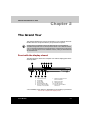
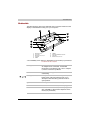
Chapter 2 The Grand Tour
Front with the display closed . . . . . . . . . . . . . . . . . . . . . . . . . . . . 2-1
Right side . . . . . . . . . . . . . . . . . . . . . . . . . . . . . . . . . . . . . . . . . . . 2-3
Left side . . . . . . . . . . . . . . . . . . . . . . . . . . . . . . . . . . . . . . . . . . . . 2-4
Underside. . . . . . . . . . . . . . . . . . . . . . . . . . . . . . . . . . . . . . . . . . . 2-6
Front with the display open . . . . . . . . . . . . . . . . . . . . . . . . . . . . . 2-7
Keyboard Indicators. . . . . . . . . . . . . . . . . . . . . . . . . . . . . . . . . . 2-10
Optical Disc drive. . . . . . . . . . . . . . . . . . . . . . . . . . . . . . . . . . . . 2-10
User’s Manual
xxvii
Chapter 3 Getting Started
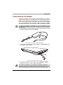
Connecting the AC adapter . . . . . . . . . . . . . . . . . . . . . . . . . . . . . 3-2
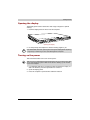
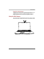
Opening the display . . . . . . . . . . . . . . . . . . . . . . . . . . . . . . . . . . . 3-3
Turning on the power. . . . . . . . . . . . . . . . . . . . . . . . . . . . . . . . . . 3-3
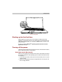
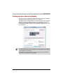
Starting up for the first time . . . . . . . . . . . . . . . . . . . . . . . . . . . . . 3-4
Turning off the power. . . . . . . . . . . . . . . . . . . . . . . . . . . . . . . . . . 3-4
Restarting the computer . . . . . . . . . . . . . . . . . . . . . . . . . . . . . . . 3-8
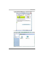
System Recovery Options . . . . . . . . . . . . . . . . . . . . . . . . . . . . . . 3-9
Restoring the preinstalled software from the Product
Recovery disc . . . . . . . . . . . . . . . . . . . . . . . . . . . . . . . . . . . . . . . 3-9
Create an Optical Recovery Discs . . . . . . . . . . . . . . . . . . . . . . . 3-10
Restoring the pre-installed software from the Recovery
Hard Disk Drive . . . . . . . . . . . . . . . . . . . . . . . . . . . . . . . . . . . . . 3-11
Restoring the pre-installed software from your created
Recovery Discs . . . . . . . . . . . . . . . . . . . . . . . . . . . . . . . . . . . . . 3-11
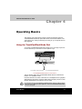
Chapter 4 Operating Basics
Using the TouchPad/Dual Mode Pad . . . . . . . . . . . . . . . . . . . . . 4-1
Dual Mode Pad Button function (Dual Mode Pad is
provided with some models) . . . . . . . . . . . . . . . . . . . . . . . . . . . . 4-2
Using the FingerPrint (FingerPrint sensor is provided
with some models) . . . . . . . . . . . . . . . . . . . . . . . . . . . . . . . . . . . . 4-3
Using the Web Camera . . . . . . . . . . . . . . . . . . . . . . . . . . . . . . . 4-11
Using the internal modem . . . . . . . . . . . . . . . . . . . . . . . . . . . . . 4-13
LAN . . . . . . . . . . . . . . . . . . . . . . . . . . . . . . . . . . . . . . . . . . . . . . 4-16
Wireless LAN . . . . . . . . . . . . . . . . . . . . . . . . . . . . . . . . . . . . . . . 4-17
Using optical disc drives . . . . . . . . . . . . . . . . . . . . . . . . . . . . . . 4-19
*Writing CDs on a CD-RW/DVD-ROM drive . . . . . . . . . . . . . . . 4-24
Writing CDs/DVDs on a DVD Super Multi drive supporting
double layer disc recording . . . . . . . . . . . . . . . . . . . . . . . . . . . . 4-26
When Using Ulead DVD MovieFactory® for TOSHIBA . . . . . . . 4-30
TOSHIBA Disc Creator. . . . . . . . . . . . . . . . . . . . . . . . . . . . . . . . 4-32
Media Care. . . . . . . . . . . . . . . . . . . . . . . . . . . . . . . . . . . . . . . . . 4-33
Disks . . . . . . . . . . . . . . . . . . . . . . . . . . . . . . . . . . . . . . . . . . . . . 4-34
TV-Out . . . . . . . . . . . . . . . . . . . . . . . . . . . . . . . . . . . . . . . . . . . . 4-34
Setting up more than one display . . . . . . . . . . . . . . . . . . . . . . . 4-35
Cleaning the computer . . . . . . . . . . . . . . . . . . . . . . . . . . . . . . . 4-36
Moving the computer. . . . . . . . . . . . . . . . . . . . . . . . . . . . . . . . . 4-36
xxviii
Satellite P200/Satellite Pro P200
Chapter 5 The Keyboard
Typewriter keys . . . . . . . . . . . . . . . . . . . . . . . . . . . . . . . . . . . . . . 5-1
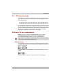
F1 ... F12 function keys . . . . . . . . . . . . . . . . . . . . . . . . . . . . . . . . 5-2
Soft keys: Fn key combinations. . . . . . . . . . . . . . . . . . . . . . . . . . 5-2
Hotkeys . . . . . . . . . . . . . . . . . . . . . . . . . . . . . . . . . . . . . . . . . . . . 5-3
Windows special keys . . . . . . . . . . . . . . . . . . . . . . . . . . . . . . . . . 5-4
Number Pad. . . . . . . . . . . . . . . . . . . . . . . . . . . . . . . . . . . . . . . . . 5-4
Generating ASCII characters . . . . . . . . . . . . . . . . . . . . . . . . . . . . 5-4
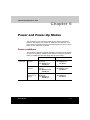
Chapter 6 Power and Power-Up Modes
Power conditions . . . . . . . . . . . . . . . . . . . . . . . . . . . . . . . . . . . . . 6-1
Power indicators . . . . . . . . . . . . . . . . . . . . . . . . . . . . . . . . . . . . . 6-3
Battery types . . . . . . . . . . . . . . . . . . . . . . . . . . . . . . . . . . . . . . . . 6-4
Care and use of the battery pack . . . . . . . . . . . . . . . . . . . . . . . . 6-5
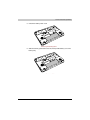
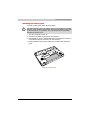
Replacing the battery pack . . . . . . . . . . . . . . . . . . . . . . . . . . . . 6-10
TOSHIBA Password Utility. . . . . . . . . . . . . . . . . . . . . . . . . . . . . 6-13
Power-up modes . . . . . . . . . . . . . . . . . . . . . . . . . . . . . . . . . . . . 6-14
Panel power off/on. . . . . . . . . . . . . . . . . . . . . . . . . . . . . . . . . . . 6-14
System automatic Sleep/Hibernation . . . . . . . . . . . . . . . . . . . . 6-14
Chapter 7 HW Setup
Accessing HW Setup . . . . . . . . . . . . . . . . . . . . . . . . . . . . . . . . . . 7-1
HW Setup Window. . . . . . . . . . . . . . . . . . . . . . . . . . . . . . . . . . . . 7-1
Chapter 8 Optional Devices
Express Card . . . . . . . . . . . . . . . . . . . . . . . . . . . . . . . . . . . . . . . . 8-2
SD/SDHC/MMC/MS/MS Pro/xD Memory cards . . . . . . . . . . . . . 8-3
Memory expansion . . . . . . . . . . . . . . . . . . . . . . . . . . . . . . . . . . . 8-6
Additional battery pack . . . . . . . . . . . . . . . . . . . . . . . . . . . . . . . . 8-9
Additional AC adapter . . . . . . . . . . . . . . . . . . . . . . . . . . . . . . . . . 8-9
Battery charger . . . . . . . . . . . . . . . . . . . . . . . . . . . . . . . . . . . . . . 8-9
External monitor. . . . . . . . . . . . . . . . . . . . . . . . . . . . . . . . . . . . . . 8-9
Television . . . . . . . . . . . . . . . . . . . . . . . . . . . . . . . . . . . . . . . . . . 8-10
i.LINK (IEEE1394a) . . . . . . . . . . . . . . . . . . . . . . . . . . . . . . . . . . . 8-15
Security lock . . . . . . . . . . . . . . . . . . . . . . . . . . . . . . . . . . . . . . . 8-16
Chapter 9 Troubleshooting
Problem solving process . . . . . . . . . . . . . . . . . . . . . . . . . . . . . . . 9-1
Hardware and system checklist. . . . . . . . . . . . . . . . . . . . . . . . . . 9-3
TOSHIBA support . . . . . . . . . . . . . . . . . . . . . . . . . . . . . . . . . . . 9-18
Satellite P200/Satellite Pro P200
xxix
Chapter 10 Disclaimers
CPU . . . . . . . . . . . . . . . . . . . . . . . . . . . . . . . . . . . . . . . . . . . . . . 10-1
Memory (Main System) . . . . . . . . . . . . . . . . . . . . . . . . . . . . . . . 10-2
Battery Life. . . . . . . . . . . . . . . . . . . . . . . . . . . . . . . . . . . . . . . . . 10-2
HDD Drive Capacity . . . . . . . . . . . . . . . . . . . . . . . . . . . . . . . . . . 10-3
LCD . . . . . . . . . . . . . . . . . . . . . . . . . . . . . . . . . . . . . . . . . . . . . . 10-3
Graphics Processor Unit (“GPU”) . . . . . . . . . . . . . . . . . . . . . . . 10-3
Wireless LAN . . . . . . . . . . . . . . . . . . . . . . . . . . . . . . . . . . . . . . . 10-3
Non-applicable Icons. . . . . . . . . . . . . . . . . . . . . . . . . . . . . . . . . 10-3
Copy Protection . . . . . . . . . . . . . . . . . . . . . . . . . . . . . . . . . . . . . 10-4
Images . . . . . . . . . . . . . . . . . . . . . . . . . . . . . . . . . . . . . . . . . . . . 10-4
LCD Brightness and Eye Strain . . . . . . . . . . . . . . . . . . . . . . . . . 10-4
Appendix A Specifications
Appendix B Display Modes
Appendix C AC Power Cord and Connectors
Glossary
xxx
Satellite P200/Satellite Pro P200
Satellite P200/Satellite Pro P200
Preface
Congratulations on your purchase of the Satellite P200/Satellite Pro P200
Series computer. This powerful notebook computer provides excellent
expansion capability, including multimedia devices, and it is designed to
provide years of reliable, high-performance computing.
This manual tells how to set up and begin using your Satellite P200/Satellite
Pro P200 Series computer. It also provides detailed information on
configuring your computer, basic operations and care, using optional
devices and troubleshooting.
If you are a new user of computers or if you're new to portable computing,
first read over the Satellite P200/Satellite Pro P200 Series Features and The
Grand Tour chapters to familiarize yourself with the computer's features,
components and accessory devices. Then read Getting Started for step-bystep instructions on setting up your computer.
If you are an experienced computer user, please continue reading the
preface to learn how this manual is organized, then become acquainted with
this manual by browsing through its pages. Be sure to look over the Special
features section of the Satellite P200/Satellite Pro P200 Series Features, to
learn about features that are unique to the computer.
User’s Manual
xxxi
Preface
Manual contents
This manual has ten chapters, three appendixes and a glossary.
Chapter 1, Satellite P200/Satellite Pro P200 Series Features, is an overview
of the computer's special features, utilities, and options.
Chapter 2, The Grand Tour, identifies the components of the computer and
briefly explains how they function.
Chapter 3, Getting Started, provides a quick overview of how to begin
operating your computer and gives tips on safety and designing your work
area. Be sure to read the sections on setting up the operating system and
on restoring the pre-installed software.
Chapter 4, Operating Basics, includes instructions on using the following
devices: TouchPad/Dual Mode Pad, the optical disc drives, the internal
modem, LAN and wireless LAN. It also provides tips on care of the computer,
disks and DVD/CD-ROMs.
Chapter 5, The Keyboard, describes special keyboard functions including
the keypad overlay and hotkeys.
Chapter 6, Power and Power-Up Modes, gives details on the computer's
power resources.
Chapter 7, HW Setup, introduces you to the TOSHIBA Hardware Setup
program.
Chapter 8, Optional Devices, describes the optional hardware available.
Chapter 9, Troubleshooting, provides helpful information on how to perform
some diagnostic tests, and suggests courses of action if the computer
doesn't seem to be working properly.
Chapter 10, Disclaimers, provides disclaimer information related to your
computer.
The Appendices provide technical information about your computer.
The Glossary defines general computer terminology and includes a list of
acronyms used in the text.
xxxii
Satellite P200/Satellite Pro P200
Preface
Conventions
This manual uses the following formats to describe, identify, and highlight
terms and operating procedures.
Abbreviations
On first appearance, and whenever necessary for clarity, abbreviations are
enclosed in parentheses following their definition. For example: Read Only
Memory (ROM). Acronyms are also defined in the Glossary.
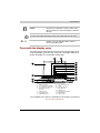
Icons
Icons identify ports, dials, and other parts of your computer. The indicator
panel also uses icons to identify the components it is providing information
on.
Keys
The keyboard keys are used in the text to describe many computer
operations. A distinctive typeface identifies the key top symbols as they
appear on the keyboard. For example, Enter identifies the Enter key.
Key operation
Some operations require you to simultaneously use two or more keys. We
identify such operations by the key top symbols separated by a plus sign
(+). For example, Ctrl + C means you must hold down Ctrl and at the same
time press C. If three keys are used, hold down the first two and at the same
time press the third.
DISKCOPY A: B:
When procedures require an action such as
clicking an icon or entering text, the icon's name
or the text you are to type in is represented in the
type face you see to the left.
Display
ABC
Satellite P200/Satellite Pro P200
Names of windows or icons or text generated by
the computer that appears on its display screen
is presented in the type face you see to the left.
xxxiii
Preface
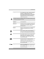
Messages
Messages are used in this manual to bring important information to your
attention. Each type of message is identified as shown below.
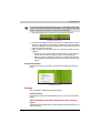
Pay attention! A caution informs you that improper use of equipment or
failure to follow instructions may cause data loss or damage your
equipment.
Please read. A note is a hint or advice that helps you make best use of your
equipment.
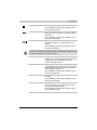
Terminology
This term is defined in this document as follows:
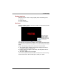
Start
The word “Start” refers to the
Microsoft® Windows Vista™.
button in
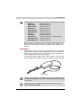
Equipment checklist
Carefully unpack your computer. Save the box and packing materials for
future use. Check to make sure you have all the following items:
Hardware
■
■
■
■
xxxiv
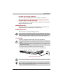
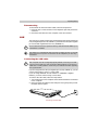
Satellite P200/Satellite Pro P200 Series Portable Personal Computer
Universal AC Adapter and Power Cord
USB Floppy Disk Drive (provided with some models)
Modular cable for modem (provided with some models)
Satellite P200/Satellite Pro P200
Preface
Software
Microsoft® Windows Vista™ Home Basic/Home Premium/Business Edition
■ The following software which is pre-installed on your hard disk:
■ Microsoft® Windows Vista™ Home Basic/Home Premium/Business
Edition
■ DVD Video Player
■ TOSHIBA Disc Creator
■ TOSHIBA ConfigFree
■ TOSHIBA Assist
■ TOSHIBA SD Memory Card Format*
■ TOSHIBA HW Setup
■ TOSHIBA Value Added Package Utility
■ TOSHIBA Supervisor Password Utility
■ Ulead DVD MovieFactory®
■ FingerPrint Utility*
■ Online Manual
■ Product Recovery disc (provided with some models)
* The availability of this software is dependent on the model you purchased.
The system may not function properly if you use drivers that are not preinstalled or distributed by TOSHIBA.
SD Memory Card Format Utility and other SD functions are packaged into
TOSHIBA SD Memoory Utilities. When uninstalling the SD utilities, click
Start Control Panel Uninstall a program, and select TOSHIBA SD
Memory Utilities.
Documentation
■ Your computer's documentation:
■ Satellite P200/Satellite Pro P200 Series Personal Computer User's
Manual
■ Microsoft® Windows Vista™ manual package (provided with some
models)
■ International Limited Warranty (ILW) Instruction (This instruction is
included only with computers sold in ILW supported areas.)
If any of the items are missing or damaged, contact your dealer immediately.
Satellite P200/Satellite Pro P200
xxxv
Preface
xxxvi
Satellite P200/Satellite Pro P200
Satellite P200/Satellite Pro P200
Chapter 1
Satellite P200/Satellite Pro P200
Series Features
This chapter identifies the computer's special features, options and
accessories.
Basic features are described in a separate pamphlet.
Some of the features described in this manual may not function properly if
you use an operating system that was not pre-installed by TOSHIBA.
Features
Please visit your region's web site for the configuration details of the model
that you have purchased.
Processor
Depending on the model you purchased:
Intel® Core™ 2 Duo Processor
Intel® Core™ Duo Processor
Intel® Pentium® Dual Core Processor
Intel® Celeron® M Processor
Disclaimer (CPU)
For more information on the Disclaimer regarding CPU, please refer to the
Disclaimers section in Chapter 10.
User’s Manual
1-1
Satellite P200/Satellite Pro P200 Series Features
Chipset
Mobile Intel® 945GM/PM, 943GML Express
Chipset
T1 CardReader & 1394a Controller PCI8402
Realtek High Definition Audio Codec ALC861D
Realtek 10M/100M/1Gbps LAN Controller
RTL8111B, 10M/100M LAN Controller RTL8101E
Memory
The graphics system in your computer may use part of the main system
memory for graphics performance and therefore reduce the amount of
system memory available for other computing activities. The amount of
system memory allocated to support graphics may vary depending on the
graphics system, applications utilized, system memory size and other
factors.
1-2
Slot
Two DDRII SO-DIMM, up to 4GB with Intel®
945PM/GM Express Chipset; up to 2GB with Intel
943GML Express Chipset can be upgraded
through the memory expansion slot.
You need to remove existing SO-DIMM if SODIMM is Maximum upgradable system memory
size is depending on the system you purchased.
L2 Cache
Depending on the model you purchased.
Intel® Core™ 2 Duo Processor with 4MB or 2MB
L2 Cache
Intel® Core™ Duo Processor with 2MB L2 Cache
Intel® Pentium® Dual Core Processor with 2MB
L2 Cache
Intel® Merom Celeron® M processor with 1MB L2
Cache.
Video RAM
Depending on the model you purchased:
Mobile Intel® 945GM/943GML Express Chipset,
up to 128MB shared with main memory.
Nvidia GeForce7600
up to 64MB shared with main memory
(for 256MB main memory),
up to 128MB shared with main memory
(for 512MB, 756MB main memory),
up to 256MB shared with main memory
(for more than 1GB main memory).
Satellite P200/Satellite Pro P200
Satellite P200/Satellite Pro P200 Series Features
BIOS
1MB Flash ROM for system BIOS
Suspend to memory or hard disk drive
Various Hotkey functions for system control
Complete ACPI 1.0b functionality
Power
Battery Pack
6-cell Lithium Ion smart battery pack with
10.8V*4000mAh
9-cell Lithium Ion smart battery pack with
10.8V*6000mAh
Approximately 12 hours or longer charging time
to 100% battery capacity with system switched
on.
Approximately 4 hours charge time to 100%
battery capacity with system switched off.
Approximately 1.5 days discharging time in Sleep
Mode for the 9-cell battery, 1 day for the 6-cell
battery.
Discharge time in shutdown mode is
approximately 1 month
* The availability of this battery is dependent on
the model you purchased.
Disclaimer (Battery Life)
For more information on the Disclaimer regarding Battery Life, please refer
to the Disclaimers section in Chapter 10.
RTC Battery
The computer has an internal battery to back up
its Real Time Clock (RTC), calender and setup
information. This battery will last for an average of
one month with no external power source.
AC adapter
The universal AC adapter provides power to the
system and recharges the batteries when they are
low. It comes with a detachable power cord.
Floppy Disk Drive devices
External USB Floppy Disk Drive (depends on the
model purchased)
Satellite P200/Satellite Pro P200
1-3
Satellite P200/Satellite Pro P200 Series Features
TouchPad/Dual Mode Pad
A TouchPad/Dual Mode Pad and control buttons
in the palm rest enable control of the on-screen
pointer.
The Dual Mode Pad is a TouchPad that provides
normal touchpad features in its default mode and
switches to a DualMode interface when the upper
right corner of the TouchPad is tapped. Tapping
the same corner again will revert to normal
pointing mode.
The volume control on the right side of the TouchPad and print button may
not function with some applications.
Display
17” TFT screen with a resolution of 1440
horizontal x 900 vertical pixels WXGA+.
Disclaimer (LCD)
For more information on the Disclaimer regarding LCD, please refer to the
Disclaimers section in Chapter 10.
Graphics controller
Nvidia GeForce7600 (Graphics controller chipset
depends on the model purchased)
The graphics controller maximizes display
performance. Refer to Display Modes section in
Appendix B for more information.
Disclaimer (Graphics Processor Unit ("GPU")
For more information on the Disclaimer regarding Graphic Processor Unit
("GPU"), please refer to the Disclaimers section in Chapter 10.
Disks
Fixed hard disk
9.5mm 2.5" hard disk drive
(60/80/100/120/160/200 GB)
12.5mm 2.5" hard disk drive
(160/200/250/300 GB)
Serial ATA 1.5 Gb/s
Disclaimer (HDD Drive Capacity)
For more information on the Disclaimer regarding HDD Drive Capacity,
please refer to the Disclaimers section in Chapter 10.
1-4
Satellite P200/Satellite Pro P200
Satellite P200/Satellite Pro P200 Series Features
CD-RW/DVD-ROM
drive
Some models are equipped with a full-size CDRW/DVD-ROM module that lets you record data
to rewritable CD/CD-RWs as well as run either
12cm (4.72") or 8cm (3.15") CD/DVDs without
using an adapter. It reads DVD-ROMs at
maximum 8x speed and CD-ROMs at maximum
24x speed. It writes CD-Rs at up to 24x speed,
CD-RWs at up to 24x speed. This drive supports
the following formats:
■ DVD-ROM
■ DVD-Video
■ CD-R
■ CD-RW
■ CD-DA
■ CD-Text
■ Photo CD (single/multi-session)
■ CD-ROM Mode1, Mode2
■ CD-ROMXA Mode2 (Form1, Form2)
■ Enhanced CD(CD-EXTRA)
DVD Super Multi
drive supporting ± R
Double Layer
Some models are equipped with a full-size DVD
Super Multi drive supporting ±R Double Layer
module with dual layer support that lets you
record data to rewritable CD/DVDs as well as run
either 12cm (4.72") or 8cm (3.15") CD/DVDs
without using an adapter. It reads DVD-ROMs at
maximum 8x speed and CD-ROMs at maximum
24x speed. It writes CD-Rs at up to 24x speed,
CD-RWs at up to 16x speed, DVD-Rs at maximum
8x speed, DVD-RWs at maximum 6x speed,
DVD+RWs at maximum 8x speed, DVD+Rs at
maximum 8x speed, DVD+R (double layer) at
maximum 4x speed, DVD-R (dual layer) at
maximum 4x speed and DVD-RAM at maximum
5x speed. This drive supports the same formats
as the CD-RW/DVD-ROM drive plus the following:
■ DVD-ROM
■ DVD-Video
■ DVD-R
■ DVD-RW
■ DVD+R
■ DVD+RW
■ DVD-RAM
■ DVD+R (double layer)
■ CD-R
■ CD-RW
■ CD-DA
■ CD-Text
■ DVD-R (dual layer)
■ Photo CD (single/multi-session)
■ CD-ROM Mode1, Mode2
■ CD-ROMXA Mode2 (Form1, Form2)
■ Enhanced CD (CD-EXTRA)
Satellite P200/Satellite Pro P200
1-5
Satellite P200/Satellite Pro P200 Series Features
Computers in this series can be configured with multiple types of optical
disc drive. For more information on the optical disc drives available, talk to
your dealer. More information on using the optical disc drive can be found
in Chapter 4, Operating Basics.
Slots (depending on configuration)
Multiple Digital
Media Card (SD/
SDHC/MMC/MS/MS
Pro/xD)
This slot lets you easily transfer data from devices,
such as digital cameras and Personal Digital
Assistants, that use flash-memory.
You can use a memory module in this slot.
Express Card
The Express Card expansion slot that can
accommodate two standard module formats; an
Express Card/34 module and an Express Card/54
module. An Express Card module is a small addin
card technology based on the PCI Express and
Universal Serial Bus (USB) interfaces.
Ports (depending on configuration)
External monitor
15-pin analog VGA port supports VESA DDC2B
compatible functions.
Universal Serial Bus
The computer has Four Universal Serial Bus
(USB) ports that comply with the USB 2.0
standard, which enables data transfer speeds
more than 40 times faster than USB 1.1 (which
this computer also supports).
i.LINK (IEEE1394a)
This port enables high-speed data transfer
directly from external devices such as digital
video cameras.
TV Out
The 4-pin S-Video port is compatible with PAL or
NTSC TV standard, supporting Macrovision 7.02
copy protection.
Multimedia
1-6
Sound system
The integrated Windows® compatible sound
system provides support for internal speakers as
well as jacks for an external microphone and
headphones.
Headphone jack
A standard 3.5mm stereo jack is provided for the
connection of external headphones or speakers.
Satellite P200/Satellite Pro P200
Satellite P200/Satellite Pro P200 Series Features
Microphone jack
A standard 3.5 mm mini microphone jack enables
connection of monaural microphone input.
Web Camera
Record/Send still or video images with this
integrated Web Camera.
Communications (depending on configuration)
Modem
An internal modem provides capability for data
and fax communication. It supports the V.90 or
V.92 standards depending on the region and
provides a modem jack for connection to a
telephone line. The speed of data and fax transfer
depends on the analog telephone line conditions.
LAN
The computer has built-in support for Ethernet
LAN (10 Mbps, 10BASE-T), Fast Ethernet LAN
(100 Mbps 100BASE-TX), or Gigabit Ethernet LAN
(1000 Mbps, 1000BASE-T).
Wireless LAN
The computer has a built-in wireless LAN miniPCIE card that is compatible with other LAN
systems that support the following: 802.11a/b/g/n
wireless LAN module/ 802.11a/b/g wireless LAN
module/ 802.11b/g wireless LAN module. It has a
Frequency Channel Selection (2.4 or 5 GHz) and
allows roaming over multiple channels.
Bluetooth
Bluetooth is a short-range wireless technology
used to create PANs (Personal Area Networks)
among your devices, and with other nearby
devices like mobile computers, mobile phones,
and digital cameras.
Security
Power-on password protection
Two level password architecture
Fingerprint authentication
Security Lock Slot
Receives an optional security lock in order to
anchor the computer to a desk or other large,
heavy object.
Satellite P200/Satellite Pro P200
1-7
Satellite P200/Satellite Pro P200 Series Features
Special features
The following features are either unique to TOSHIBA computers or are
advanced features, which make the computer more convenient to use.
Hotkeys
Key combinations that let you quickly modify the
system configuration directly from the keyboard
without running a system configuration program.
Display Automatic
Power off
This feature automatically cuts off power to the
internal display when there is no input from the
keyboard or pointing device for a specified time
period. Power is restored when any key is pressed
or when there is input from a pointing device. You
can specify the time period in the TOSHIBA Power
Saver utility.
Hard Disk Drive
This feature automatically cuts off power to the
Automatic Power Off hard disk drive when it is not accessed for a
specified time period. Power is restored when the
hard disk is accessed. You can specify the time
period in the TOSHIBA Power Saver utility.
1-8
System Automatic
Sleep/Hibernation
This feature automatically places the system into
either Sleep Mode or Hibernation Mode when
there is no input or hardware access for a
specified time period. You can specify the time
period and select either System Sleep or System
Hibernate in the TOSHIBA Power Saver utility.
Keypad Overlay
A ten-key pad is integrated into the keyboard.
Refer to the Keypad overlay section in Chapter 5,
The Keyboard, for instructions on using the
keypad overlay.
Power-on Password
Two levels of password security are available,
Supervisor and User, which can prevent
unauthorized access to your computer.
Battery Save Mode
This feature lets you save battery power. You can
specify the level of system power management in
the TOSHIBA Power Saver utility.
Instant Security
A Hotkey function which blanks the screen and
activates password security to provide quick and
easy data security.
Panel Power Off/On
This feature turns power to the computer off when
the display panel is closed and turns it back on
when the panel is opened. You can specify the
setting in the TOSHIBA Power Saver utility.
Satellite P200/Satellite Pro P200
Satellite P200/Satellite Pro P200 Series Features
Low Battery
Automatic
Hibernation
When battery power is exhausted to the point that
computer operation cannot be continued, the
system automatically enters Hibernation Mode
and shuts itself down. You can specify the setting
in the TOSHIBA Power Saver utility.
Hibernation
This feature lets you turn off the power without
exiting from your software. The contents of main
memory are saved to the hard disk. When you turn
on the power again, you can continue working
right where you left off. Refer to the Turning off
the power section in Chapter 3, Getting Started,
for details.
Sleep
In Sleep Mode, power to the system remains on,
but the processor and all other devices are
effectively in 'sleep mode'. When the computer is
in Sleep Mode, the Power LED flashes amber. The
computer enters Sleep Mode regardless of the
Hibernate Mode setting. Refer to the Turning off
the power section in Chapter 3, Getting Started,
for details..
Fingerprint
Adds an additional layer of security to your files
by requiring a valid fingerprint to access them.
■ Before entering Sleep mode, be sure to save your data.
■ Do not install or remove a memory module while the computer is in Sleep
mode. The computer or the module could be damaged.
■ Do not remove the battery pack while the computer is in Sleep mode.
Data in memory will be lost.
TOSHIBA Value Added Package
This section describes the TOSHIBA Component features pre-installed on
the computer.
TOSHIBA Power
Saver
TOSHIBA Power Saver provides you with the
features of more various power supply
managements.
TOSHIBA Button
Support
This utility controls the buttom operation of the
computer. The starting application from the
buttom can be changed.
TOSHIBA PC
Diagnostic Tool
The TOSHIBA PC Diagnostic Tool will display
basic system configuration information and allow
the functionality of some of the computer’s builtin
hardware devices to be tested.
Satellite P200/Satellite Pro P200
1-9
Satellite P200/Satellite Pro P200 Series Features
TOSHIBA Flash
Cards
This utility supports the following functions,
■ Hot key function
■ TOSHIBA utility launcher function
TOSHIBA
Components
Common Driver
TOSHIBA Components Common Driver contains
the module required for the utility which TOSHIBA
offers.
TOSHIBA
Accessibility
The TOSHIBA Accessibility utility provides
support to movement impaireed users when they
need to use the TOSHIBA Hot-key functions. In
use, the utility allows you to make the Fn key
‘sticky’, that is you can press it once, release it,
and they press one of the ‘F’ keys in order to
access its specific function. When set, the Fn key
will remain active until another key is pressed.
TOSHIBA Zooming
Utility
This utility allows you to enlarge or reduce the icon
size on Windows Desktop or the zoom factor
associated with specific supported applications.
Utilities and Applications
This section describes preinstalled utilities and tells how to start them. For
details on operations, refer to each utility’s online manual, help files or
readme.txt files.
TOSHIBA Assist
TOSHIBA Assist is a graphical user interface that
provides easy access to help and services.
DVD Video Player
The DVD player is used to play DVD Video media
through an on-screen interface and functions.
TOSHIBA ConfigFree ConfigFree is a suite of utilities to allow easy
control of communication devices and network
connections. ConfigFree also allows you to find
communication problems and create profiles for
easy switching between location and
communication networks.
To start ConfigFree, click the Start Button, point
to All Programs, point to TOSHIBA, point to
Networking and click ConfigFree.
1-10
Satellite P200/Satellite Pro P200
Satellite P200/Satellite Pro P200 Series Features
TOSHIBA Disc
Creator
You can create discs in several formats including
audio CDs that can be played on a standard
stereo CD player and data discs to store the files
and folders on your hard disk drive. This software
can be used on a model with a CD-RW/DVD-ROM
drive or a DVD Super Multi drive.
TOSHIBA DVD-RAM
Utility
TOSHIBA DVD-RAM Utility has the function of
Physical Format and Write-Protect to DVD-RAM.
This utility is contained the setup module of
TOSHIBA Disc Creator. You can boot TOSHIBA
DVD-RAM Utility from the menu bar as follows.
Start -> All Programs -> TOSHIBA -> CD&DVD
Applications -> DVD-RAM Utility.
TOSHIBA Hardware
Setup
This program lets you customize your hardware
settings according to the way you work with your
computer and the peripherals you use. To access
this utility, click the Start Button, point to All
Programs, point to TOSHIBA, point to Utilities,
point to HWsetup.
CD/DVD Drive
Acoustic Silencer
This utility allows you to configure the read speed
of CD drive. You can either configure Normal
Mode, which operates the drive at its maximum
speed for quick data access, or Quiet Mode,
whcih runs at single speed for CD audio and
which can lessen operational noise. It is
ineffective in DVD.
Ulead DVD
MovieFactory® for
TOSHIBA
You can edit digital video and make a DVD-Video
and support Label Flash function.
The availability of Label Flash function depends on the model you
purchased.
Satellite P200/Satellite Pro P200
1-11
Satellite P200/Satellite Pro P200 Series Features
FingerPrint utility
This product has a fingerprint utility installed for
the purpose of enrolling and recognizing
fingerprints. (depending on the model
purchased.) By enrolling the ID and password to
the fingerprint authentication device, it is no
longer necessary to input the password from the
keyboard. Just by swiping the finger against the
fingerprint sensor, the following functions will be
enabled:
■ Logon to Windows and access a securityenabled homepage through IE (Internet
Explorer).
■ Files and folders can be encrypted/decrypted
and third party access to them prevented.
■ Disable the password-protected screensaver when returning from power-saving
(Sleep) mode.
■ System boot authentication and Single Touch
Boot feature.
■ Power on Security and Single Sign On feature.
Fingerprint cannot be used in models that do not have a fingerprint module
installed.
Windows Mobility
Center
1-12
Mobility Center is a utility for accessing several
mobile PC settings quickly in one window. A
default maximum of eight tiles are provided by the
operating system, and the additional two titles are
added to your Mobility Center
■ Lock Computer:
This can be used to lock your computer
without turning it off. This has the same
function as the Lock button at the bottom of
the right pane in the start menu.
■ TOSHIBA Assist:
This can be used to open TOSHIBA Assist if
it is already installed in your computer.
Satellite P200/Satellite Pro P200
Satellite P200/Satellite Pro P200 Series Features
Options
You can add a number of options to make your computer even more
powerful and convenient to use. The following options are available:
Memory Modules
Two memory module can be installed in this
computer.
Use only PC4200 and PC5300* compatible DDRII memory modules. See
your TOSHIBA dealer for details.
* The availability of DDRII is dependent on the model you purchased.
Battery Pack
An additional battery pack can be purchased from
your TOSHIBA dealer. Use it as a spare to
increase your computer operating time.
High capacity battery
pack
An additional battery pack can be purchased from
your TOSHIBA dealer. Use it as a spare to
increase your computer operating time.
AC adapter
If you use your computer at more than one site
frequently, it may be convenient to purchase an
additional AC adapter for each site so you will not
have to carry the adapter with you.
USB Floppy Disk
Drive
Lets you attach a floppy disk drive to your
computer by means of a USB cable.
Satellite P200/Satellite Pro P200
1-13
Satellite P200/Satellite Pro P200 Series Features
1-14
Satellite P200/Satellite Pro P200
Satellite P200/Satellite Pro P200
Chapter 2
The Grand Tour
This chapter identifies the various components of your computer. Become
familiar with each component before you operate the computer.
Certain types of notebook chassis are designed to accommodate all
possible configurations for an entire product series. Your selected model
may not have all the features and specifications corresponding to all of the
icons or switches shown on the notebook chassis, unless you have selected
all those features.
Front with the display closed
The following figure shows the computer front with its display panel in the
closed position.
1
7
2
8
1.
2.
3.
4.
5.
6.
9
10
3
4
5
6
11
FRONT EDGE LOGO*
DC IN LED
POWER LED
BATTERY LED
HARD DISK DRIVE LED
MULTIPLE DIGITAL MEDIA
CARD SLOT ACCESS LED*
7.
8.
9.
10.
11.
WIRELESS COMMUNICATION
SWITCH AND LED*
MICROPHONE JACK
HEADPHONE JACK
VOLUME CONTROL
MULTIPLE DIGITAL MEDIA
CARD SLOT*
* The availability of this feature is dependent on the model you purchased.
Front of the computer with display closed
User’s Manual
2-1
The Grand Tour
2-2
Front Edge Logo*
Front Edge Logo indicates the computer series
you bought.
(The avaliability of this function is dependent on
the model you purchased.)
DC IN LED
The DC IN LED indicates the computer is
connected to the AC adapter and it is plugged into
an AC power source.
Power LED
In normal operating mode, the Power LED is blue
(depending on the model you purchased). If the
system is in SleepSleep Mode the LED will flash
amber, while the LED will be off when the
computer is turned off or is in Hibernation Mode.
Battery LED
The Battery LED indicates the battery's current
charge/discharge status. It lights blue (depending
on the model you purchased) when the battery is
fully charged. It lights amber while the battery is
being charged from the AC adapter. It flashes
amber when the battery capacity is low.
Hard Disk Drive LED
The Hard Disk Drive LED indicates that the hard
disk drive is being accessed. Every time your
computer runs a program, opens a file, or
performs some other function in which it must
access the hard disk drive, this light will go on.
Multiple Digital
Media Card Slot
Access LED*
The Multiple Digital Media Card Slot Access LED
lights up when the Multiple Digital Media Card is
accessed.
(The avaliability of this function is dependent on
the model you purchased.)
Wireless
Communication
Switch and LED*
The wireless communication switch turns on the
wireless networking transceiver. The Wireless
Communication LED beside it indicates that
wireless networking is turned on. Indicates
whether the Wireless devices is active or not.
(The avaliability of this function is dependent on
the model you purchased.)
Microphone Jack
The standard 3.5 mm mini microphone jack
enables connection of a three conductive type
mini-jack for a monaural microphone.
Headphone Jack
The headphone jack lets you connect stereo
headphones or other audio-output devices such
as external speakers. Connecting headphones or
other devices to this jack automatically disables
the internal speakers.
Satellite P200/Satellite Pro P200
The Grand Tour
Volume Control
Use this dial to adjust the volume of the stereo
speakers or headphones.
Multiple Digital
Media Card Slot*
The Multiple Digital Media Card Slot allows you to
use media cards from digital still cameras and
various forms of portable information equipment.
(The availability of this function depends on the
model you purchased.)
Right side
The following figure shows the computer's right side.
1
2
1.
2.
3
UNIVERSAL SERIAL BUS
(USB) PORT
MODEM JACK
4
3.
4
5
5
OPTICAL DISC DRIVE AND LED
FAN VENTS
SECURITY LOCK
The right side of the computer
Universal Serial Bus
(USB) Port
The Universal Serial Bus (USB 2.0 and 1.1
compatible) port enables USB-equipped devices
such as keyboards, mice, hard drives, scanners,
and printers to be connected to the computer.
Modem Jack
In regions where an internal modem is installed as
standard equipment, this jack lets you use a
modular cable to connect the modem directly to
a telephone line.
Optical Disc Drive
and LED
The computer is configured with a full-size optical
disc drive module that lets you run either 12 cm
(4.72") or 8 cm (3.15") discs without using an
adapter. See the Drives section in this chapter for
technical specifications on each drive and
Chapter 4, Operating Basics, for information on
using the drive and caring for discs.The LED lets
you know when the Optical Disc Drive is being
accessed.
Fan Vents
The fan vents help prevent the CPU from
overheating.
Satellite P200/Satellite Pro P200
2-3
The Grand Tour
To prevent possible over heating of the CPU, never block the fan vents.
Security Lock
An optional security cable attaches to this port in
order to anchor your computer to a desk or other
large object to deter theft.
Left side
The following figure shows the computer's left side.
1
2
1.
2.
3.
4.
3
DC IN 19V JACK
RGB MONITOR PORT
FAN VENTS
LAN JACK
4
5.
6.
7
8
5
6
7
8
UNIVERSAL SERIAL BUS
(USB) PORT
TV OUT PORT
i.LINK (IEEE1394a) PORT*
EXPRESS CARD SLOT
* The availability of this feature is dependent on the model you purchased.
The left side of the computer
DC IN 19V Jack
The DC IN jack is where you plug in the AC
adapter.
RGB Monitor Port
This 15-pin port lets you connect an external
video display to the computer.
Fan Vents
The fan vents help prevent the CPU from
overheating.
To prevent possible over heating of the CPU, never block the fan vents.
2-4
Satellite P200/Satellite Pro P200
The Grand Tour
LAN Jack
This jack lets you connect to a LAN. The adapter
has built-in support for Ethernet LAN (10
megabits per second, 10BASE-T), Fast Ethernet
LAN (100 megabits per second, 100BASE-TX)
and Gigabit Ethernet LAN (1000 megabits per
second, 1000BASE-T). Two indicators built into
the jack let you see the LAN status.
Universal Serial Bus
(USB) Port
The Universal Serial Bus (USB 2.0 and 1.1
compatible) port enables USB-equipped devices
such as keyboards, mice, hard drives, scanners,
and printers to be connected to the computer.
TV Out Port
Connect a 4-pin S- video cable into this connector
in order to output either an NTSC or PAL television
signal.
i.LINK (IEEE1394a)
Port
This port allows you to connect an external
device, such as a digital video camera, for highspeed data transfer.
Express Card Slot
This slot allows you to insert an Express Card. An
Express Card module is a small, modular add-in
card technology based on PCI Express and
Universal Serial Bus (USB) interface. The max.
transmission rate at 2.5Gbps. Both 34mn type
and 54mm type are supported.
Satellite P200/Satellite Pro P200
2-5
The Grand Tour
Underside
The following figure shows the underside of the computer. Make sure the
display is closed before turning over your computer.
6
5
4
3
2
7
8
9
1
1.
2.
3.
4.
5.
BATTERY PACK
FAN VENT
BATTERY PACK LOCK
SPEAKER
HDD1
6.
7.
8.
9.
HDD2*
EXPANSION MEMORY SOCKET
FAN VENT
BATTERY PACK LATCH
* The availability of this feature is dependent on the model you purchased.
The bottom of the computer
2-6
Battery Pack
The battery pack powers the computer when the
AC adapter is not connected. For detailed
information on the battery pack, refer to Chapter
6, Power and Power-Up Modes.
Fan Vent
The fan vents help prevent the CPU from
overheating.
Battery Pack Lock
When you slide this into its locked position, the
battery pack cannot be released even if you
attempt to slide the battery pack latch into its
open position.
Speaker
A third speaker to indicate bios beeps.
HDD1
Hard Disk Drives store data, files and programs.
HDD2*
Hard Disk Drives store data, files and programs.
(The availability of this function depends on the
model you purchased.)
Satellite P200/Satellite Pro P200
The Grand Tour
Expansion Memory
Socket
Use this socket to install a memory module to
increase your computer's memory. Refer to the
Memory expansion section in Chapter 8, Optional
Devices.
To prevent possible overheating of the CPU, never block the fan vents.
Battery Pack Latch
With the Battery Pack Lock in its unlocked
position, you can slide this latch in order to
remove the battery pack.
Front with the display open
The following figure shows the front of the computer with the display open.
To open the display, push the latch on the front of the display and lift it up.
Position the display at a comfortable viewing angle.
14
15
5
1
6
7
8
9
10
11
2
12
3
13
4
1.
2.
3.
4.
5.
6.
7.
DISPLAY SCREEN
LEFT AND RIGHT SPEAKERS
TOUCHPAD/DUAL MODE PAD
TOUCHPAD CONTROL
BUTTONS
POWER BUTTON
INTERNET BUTTON*
CD/DVD BUTTON*
8.
9.
10.
11.
12.
13.
14.
15.
PLAY/PAUSE BUTTON*
STOP*
PREVIOUS BUTTON*
NEXT BUTTON*
NUMBER PAD
FINGER PRINT SCANNER*
WEB CAMERA*
MICROPHONE*
* The availability of this feature is dependent on the model you purchased.
The front with the display open
Satellite P200/Satellite Pro P200
2-7
The Grand Tour
Display Screen
The LCD displays high-contrast text and graphics
at a resolution up to 1680 x 1050 pixels. Refer to
Appendix B - Display Modes for further
information. When the computer operates from
the AC adapter, the display screen's image will be
somewhat brighter than when it operates on
battery power - this is normal and is designed to
conserve battery power.
To prolong the life of your display screen, use a screen saver when you're
not using the computer and it is idle.
2-8
Left and Right
Speakers
The computer provides two speakers for stereo
sound reproduction.
TouchPad/Dual
Mode Pad
The TouchPad/Dual Mode Pad pointing device is
located in the centre of the palm rest and is used
to control the on-screen pointer. Refer to the How
the Swipe the Finger section in Chapter 4,
Operating Basics.
TouchPad Control
Buttons
Control buttons below the TouchPad/Dual Mode
Pad let you select menu items or manipulate text
and graphics designated by the on-screen
pointer.
Power Button
Press the power button to turn the computer's
power on and off. There is an LED inside the
power button which shines in blue (depending on
the model you purchased) when the system is on.
Internet Button*
Press this button to launch an Internet browser.If
the computer’s power is off, you can press this
button to turn on the computer’s power and
launch the browser automatically in one step.
(The availability of this function depends on the
model you purchased.)
CD/DVD Button*
Pressing this button will launch an application
program that allows for watching CD/DVD.
An application that is launched differs by a model:
Windows Media Player/DVD Video Player.
(The availability of this function depends on the
model you purchased.)
Play/Pause Button*
Press this button to begin playing an audio CD, a
DVD movie or digital audio files. This button also
acts as a Pause button.
(The availability of this function depends on the
model you purchased.)
Satellite P200/Satellite Pro P200
The Grand Tour
Stop*
Stops playing the CD, DVD or digital audio.
(The availability of this function depends on the
model you purchased.)
Previous Button*
Skips backwards to the previous track, chapter or
digital file. Refer to Chapter 4, Operating Basics,
for details.
(The availability of this function depends on the
model you purchased.)
Next Button*
Skips forward to the next track, chapter or digital
file. Refer to Chapter 4, Operating Basics, for
details.
(The availability of this function depends on the
model you purchased.)
If Random or Shuffle is selected in Windows® Media Player, selecting Next
or Previous advances to a random selection.
Number Pad
Press the Number Lock button to activate the
number pad. Use the number pad instead of the
number buttons on the keyboard to enter
numbers and ASCII codes.
Finger Print Scanner* Use the fingerprint scanner to prevent
unauthorised access to the laptop See “Using the
FingerPrint (FingerPrint sensor is provided with
some models)” on page 4-3.
(The availability of this function depends on the
model you purchased.)
Web Camera*
Take your picture or send your image to web
contacts.
(The availability of this function depends on the
model you purchased.)
Microphone*
The Microphone is used with the Web Camera to
talk to other Web Camera users and to record
messages on windows media.
(The availability of this function depends on the
model you purchased.)
Satellite P200/Satellite Pro P200
2-9
The Grand Tour
Keyboard Indicators
Numeric Mode
You can use the keypad overlay (light gray labeled
keys) for numeric input when the Numeric mode
icon lights blue. Refer to the Keypad overlay
section in Chapter 5, The Keyboard.
Caps Lock
The Caps Lock LED lights when you press the
Caps Lock key. When this light is on, pressing a
letter key on the keyboard produces an
uppercase (capital) letter.
Optical Disc drive
The computer will either have a CD-RW/DVD-ROM drive, or a single layer
or dual layer DVD Super Multi drive supporting ±R Double Layer depending
on its configuration. An ATAPI interface controller is used for the operation
of these optical drives. When the computer is accessing a disc, an indicator
on the drive glows.
Region codes for DVD drives and media
The disc drive and its media are manufactured according to the
specifications of six marketing regions. When you purchase DVD-Video,
make sure it matches your drive, otherwise it will not play properly.
Code
2-10
Region
1
Canada, United States
2
Japan, Europe, South Africa, Middle East
3
Southeast Asia, East Asia
4
Australia, New Zealand, Pacific Islands, Central
America, South America, Caribbean
5
Russia, Indian Subcontinent, Africa, North Korea,
Mongolia
6
China
Satellite P200/Satellite Pro P200
The Grand Tour
Writable discs
This section describes the types of writable discs. Check the specifications
for your drive to for the type of discs it can write. Use TOSHIBA Disc Creator
to write compact discs. Refer to Chapter 4, Operating Basics.
CDs
■ CD-R discs can be written only once. The recorded data cannot be
erased or changed.
■ CD-RW discs can be recorded more than once. Use either 1x, 2x, or 4x
multi-speed CD-RW discs or high-speed 4x to 10x discs. The write
speed of ultra-speed CD-RW discs is a maximum of 24x speed.
DVDs
■ DVD-R and DVD+R discs can be written only once. The recorded data
cannot be erased or changed.
■ DVD-RW, DVD+RW and DVD-RAM discs can be recorded more than
once.
CD-RW/DVD-ROM drive
The full-size CD-RW/DVD-ROM drive module lets you record data to
rewritable CDs as well as run either 12 cm (4.72") or 8 cm (3.15") discs
without using an adapter.
The read speed is slower at the centre of a disc and faster at the other edge.
DVD read
8 speed (maximum)
CD read
24 speed (maximum)
CD-R write
24 speed (maximum)
CD-RW write
24 speed (maximum, ultra-speed media)
DVD Super Multi drive supporting ±R Double Layer
The full-size DVD Super Multi drive supporting ±R Double Layer module lets
you record data to rewritable discs as well as run either 12cm (4.72") or 8cm
(3.15") discs without using an adapter.
Satellite P200/Satellite Pro P200
2-11
The Grand Tour
The read speed is slower at the centre of a disc and faster at the other edge.
DVD read
8 speed (maximum)
DVD-R write
8 speed (maximum)
DVD-RW write
6 speed (maximum)
DVD+R write
8 speed (maximum)
DVD+RW write
8 speed (maximum)
DVD-RAM write
5 speed (maximum)
CD read
24 speed (maximum)
CD-R write
24 speed (maximum)
CD-RW write
16 speed (maximum, ultra-speed media)
DVD+R (DL) write 4 speed (maximum)
DVD-R(DL) write
4 speed (maximum)
This drive cannot use discs that allow writing faster than 8x speed or faster
(DVD-R and DVD+R with Single Layer), 6x speed or faster (DVD-RW), 8x
speed or faster (DVD+RW), 5x speed (DVD-RAM) or ultra-speed or faster
(CD-RW).
AC adapter
The AC adapter converts AC power to DC power and reduces the voltage
supplied to the computer. It can automatically adjust to any voltage from
100 to 240 volts and to a frequency of either 50 or 60 hertz, enabling you to
use the computer in almost any country/region.
To recharge the battery, simply connect the AC adapter to a power source
and the computer. See Chapter 6, Power and Power-Up Modes, for details.
The AC adapter
Use of the wrong adapter could damage your computer. TOSHIBA assumes
no liability for any damage in such case. The output rating for the computer
is 19 volts DC.
Please use only the AC Adapter supplied with the computer or an AC
adapter certified by TOSHIBA.
2-12
Satellite P200/Satellite Pro P200
Satellite P200/Satellite Pro P200
Chapter 3
Getting Started
This chapter provides basic information to get you started using your
computer. It covers the following topics:
Be sure also to read Instruction Manual for Safety & Comfort. This guide,
which is included with the computer, explains product liability.
■
■
■
■
■
■
■
Connecting the AC adapter
Opening the display
Turning on the power
Starting up for the first time
Turning off the power
Restarting the computer
Restoring the pre-installed software from the Product Recovery media.
All users should be sure to carefully read the section Starting up for the first
time, which describes the actions to take when you turn on the power for
the first time.
User’s Manual
3-1
Getting Started
Connecting the AC adapter
Attach the AC adapter when you need to charge the battery or you want to
operate from AC power. It is also the fastest way to get started, because
the battery pack will need to be charged before you can operate from battery
power. The AC adapter can be connected to any power source supplying
from 100 to 240 volts and 50 or 60 hertz. For details on using the AC adapter
to charge the battery pack, refer to Chapter 6, Power and Power-Up Modes.
Use of the wrong adapter could damage your computer. TOSHIBA assumes
no liability for any damage in such case. The output rating for the computer
is 19 volts DC.
1. Connect the power cord to the AC adapter.
Connecting the power cord to the AC adapter
2. Connect the DC output plug on the AC adapter to the DC IN input port
on the back of the computer.
Connecting the adapter to the computer
3. Plug the power cord into a live wall outlet. The Battery and DC IN
indicators on the front of the computer should glow.
To disconnect AC adaptor, you can follow the reversed procedure of
Connecting AC adaptor. Please hold the DC output plug portion by your
fingers and then plug it out when you disconnect the DC output plug.
3-2
Satellite P200/Satellite Pro P200
Getting Started
Opening the display
The display panel can be rotated in a wide range of angles for optimal
viewing.
1. Push the display latch on the front of the computer.
Opening the display
2. Lift the panel up and adjust it to the best viewing angle for you.
Use reasonable care when opening and closing the display panel. Opening
it vigorously or slamming it shut could damage the computer.
Turning on the power
This section describes how to turn on the power.
After you turn on the power for the first time, do not turn it off until you have
set up the operating system. Refer to the section Starting up for the first
time in this chapter.
1. If a USB floppy disk drive is connected, make sure the drive is empty - if a
disk is in the drive, press the eject button to remove it.
2. Open the display panel.
3. Press the computer's power button and then release it.
Satellite P200/Satellite Pro P200
3-3
Getting Started
Turning on the power
Starting up for the first time
When you first turn on the power, the computer's initial screen is the
Windows® Vista Startup Screen Logo. Follow the on-screen directions for
each screen. During setup, you can click the Back button to return to the
previous screen.
Be sure to read the Windows® Operating System End User License
Agreement carefully.
Turning off the power
The power can be turned off in one of three modes, either Shutdown (Boot)
Mode, Hibernation Mode or Sleep Mode.
Shut Down mode (Boot mode)
When you turn off the power in Shut Down mode no data will be saved and
the computer will boot to the operating system's main screen the next time
it is turned on.
1. If you have entered data, either save it to the hard disk, drive or to other
storege media.
2. Make sure all disk/disks activity has stopped before removing the CD/
DVD or floppy diskette.
3-4
Satellite P200/Satellite Pro P200
Getting Started
■ Make sure the Hard Disk Drive indicators is off. If you turn off the power
while a disk (disks) is being accessed, you can lose data or damage the
disk.
■ Never turn off the power while an application is running. Doing so could
cause loss data.
■ Never turn off the power, disconnect an external storage device or
remove storage media during data read/write. Doing so can cause data
loss.
3. Click Start then click the arrow button (
) located in the power
management buttons (
) and select Shut Down from the
menu.
4. Turn off any peripheral devices connected to your computer.
Do not turn the computer or peripheral devices back on immediately - wait
a short period to avoid and peripheral damage.
Sleep Mode
If you do have to interrupt your work, you are able to turn off the power
without exiting from your software by placing the computer into Sleep Mode.
In this mode data is maintained in the computer’s main memory so that,
when you turn on the power again, you can continue working right where
you left off
■ When the AC adaptor is connected, the computer will go into Sleep
Mode according to the settings in the Power Options.
■ To restore the operation from the computer from Sleep Mode, press the
power button or press any key. Please be aware that this latter action
only works on the internal keyboard if the. Wake-up on Keyboard option
is enabled within the HW Setup utility.
■ If the computer enters Sleep Mode while a network application is active,
the application might not be restored when the computer is next turned
on and the system returns from Sleep Mode.
■ To prevent the computer from automatically entering Sleep Mode,
disable Sleep Mode within the Power Options. However, please be
aware that this configuration will nullify the computer’s Energy Star
compliance.
■ Before entering Sleep Mode, be sure to save your data.
■ Do not install or remove a memory module while the computer is in Sleep
Mode. The Computer or the module could be damaged.
■ Do not remove the battery pack while the computer is in Sleep Mode
(unless the computer is connected to an AC power source). Data in
memory will be lost.
Satellite P200/Satellite Pro P200
3-5
Getting Started
Benefits of Sleep Mode
The Sleep Mode feature provides the following benefits:
■ Restore the previous working enviroment more rapidly than does the
Hibernation Mode feature.
■ Saves power by shutting down the system when the computer receives
no input or hardware access for the time period set by the System Sleep
Mode feature.
■ Allows the use of the panel power off feature.
Executing Sleep Mode
You can enter also Sleep Mode by pressing Fn + F3 - please refer to
Chapter 5, The Keyboard, for further details.
Youu can enter Sleep Mode in one of three ways:
1. Click Start then click the sleep button (
) located in the power
management buttons (
), or click the arrow button (
) and
select Sleep from the menu.
2. Close the computer’s LCD display panel. Please note that this feature
must be enabled - please refer to the Power Options (to access it, click
Start followed by Control Panel followed by System and Maintenance
and then click the Power Options).
3. Press the power button. Please note that this feature must be
enabled - please refer to the Power Options (to access it, click Start
followed by Control Panel followed by System and Maintenance and
then click the Power Options and point to Choose what the power button
do).
When you turn the power back on, you can continue where you left when
you shutdown the computer.
■ When the computer is in Sleep Mode, the power indicator will blink
orange.
■ If you are operating the computer on battery power, you can lengthen
the overall operating time by turning it off into Hibernation Mode - Sleep
Mode will consume more power while the computer is off.
Sleep Mode limitations
Sleep Mode will not function under the following conditions:
■ Power is turned back on immediately after shutting down.
■ Memory circuits are exposed to static electricity or electrical noise.
Hibernation mode
The Hibernation Mode feature saves the contents of memory to the hard
disk drive when the computer is turned off so that, the next time it is turned
on, the previous state is restored. Please note that the Hibernation Mode
feature does not save the status of any peripheral devices connected to the
computer.
3-6
Satellite P200/Satellite Pro P200
Getting Started
■ Save your data. While entering Hibernation Mode, the computer saves
the contents of memory to the hard disk drive. However, for safety sake,
it is best to save your data manually.
■ Data will be lost if you remove the battery or disconnect the AC adaptor
before the save is completed. Wait for the Hard Disk Drive indicator to
go out.
■ Do not install or remove a memory module while the computer is in
Hibernation Mode. Data will be lost.
Benefits of Hibernation Mode
The Hibernation Mode feature provides the following benefits:
■ Saves Data to the hard disk drive when the computer automatically
shutsdown because of a low battery condition.
■ You can return to your previous working environment immediately when
you turn on the computer.
■ Saves power by shutting down the system when the computer receives
no input or hardware access for the time period set by the System
Hibernate feature.
■ Allows the use of the panel power off feature.
Starting Hibernation Mode
You can also enable Hibernation Mode by pressing Fn + F4 - please refer
to Chapter 5, The Keyboard, for further details.
To enter Hibernation Mode, follow the steps below.
1. Click Start.
2. Click the arrow button (
) in the power management buttons
(
).
3. Select Hibernate from the menu.
Satellite P200/Satellite Pro P200
3-7
Getting Started
Automatic Hibernation Mode
The computer can be configured to enter Hibernate Mode automatically
when you press the power button or close the lid. In order to define these
settings, you can follow the steps as described below:
1. Click Start and click the Control Panel.
2. Click System and Maintenance and click Power Options.
3. Click Choose what the Power Button do or Choose what closing the lid
does.
4. Enable the desired Hibernation Mode settings for When I press the
power button or When I close the lid.
5. Click the Save Changes button.
Data save in Hibernation Mode
When you turn off the power in Hibernation Mode, the computer takes a
moment to save the current data in memory to the hard disk drive. During
this time, the Hard Disk Drive indicator will glow.
After you turn off the computer, and the content of memory has been saved
to the hard disk drive, turn off the power to any peripheral devices.
Do not turn the computer or devices back on immediately. Wait a moment
to let all capacitors fully discharge.
Restarting the computer
Certain conditions require that you reset the computer, for example if:
■ You change certain computer settings.
■ An errors and the computer does not respond you your keyboard
commands.
If you need to restart the computer, there are three ways this can be
achieved:
1. Click Start then click the arrow button (
) in the power management
buttons (
) and select Restart from the menu.
2. Press Ctrl+Alt+Del to display the menu window, then select Restart from
the Shutdown options.
3. Press the power button and hold it down for five seconds. Once the
computer has turned itself off, wait between ten and fifteen seconds
before turning the power on again by pressing the power button.
3-8
Satellite P200/Satellite Pro P200
Getting Started
System Recovery Options
About 1.5GB hidden partition is allocated on the hard disk drive for the
System Recovery Options.This partition stores files which can be used to
repair the system in the event of a problem.
The System Recovery Options feature will be unusable if this partition is
deleted.
System Recovery Options
The System Recovery Options feature is installed on the hard disk when
shipped from the factory. In the event that an error occurs between the time
power is turned ON and login, and the error is repairable, the Windows
Recovery Enviroment will automatically repair the error.
The Window Recovery Environment can also be run manually to repair
errors.
The procedure is as follows. Follow the instructions shown on the on-screen
menu.
1. Turn off the computer.
2. While holding the F8 key, turn the computer again.
3. The Advanced Boot Options menu will be displayed.
Use the arrow keys to select Repair Your Computer and press Enter.
4. Follow the on-screen instructions.
The Windows Vista™ Complete PC Backup feature can be used on
Windows Vista™ Business Edition and Ultimate Edition.
Restoring the preinstalled software from the Product
Recovery disc
If preinstalled files are damaged, use the Product Recovery disc to restore
them. To restore the operating system and all preinstalled software, follow
the steps below.
When you reinstall the Windows operating system, the hard disk will be
reformatted and all data will be lost. You can not use System Recovery
Options if restoring the pre-installed software without System Recovery
options.
1. Load the Product Recovery disc in the drive and turn off the computer's
power.
2. Switch on the computer and, when the In Touch with Tomorrow
TOSHIBA prompt appears, press the F12 key to display the Boot Menu.
3. Use the up or down cursor key to select the CD-ROM/DVD drive in the
display menu.
4. Follow the on-screen instructions.
Satellite P200/Satellite Pro P200
3-9
Getting Started
When removing pre-installed drivers / utilities or when installing, you can
setup the respective drivers / utilities from the following folder.
C: \TOSAPINS\***
When Installing TOSHIBA SD Memory Card Format or other SD utilities,
select TOSHIBA SD Memory Utilities from C:\TOSAPINS\.
Create an Optical Recovery Discs
■ Be sure to connect the AC adaptor when you create Recovery Discs.
■ Be sure to close all other software programs except the Recovery Disc
Creator.
■ Do not run software such as screen savers which can put a heavy load
on the CPU.
■ Operate the computer at full power.
■ Do not use power-saving features.
■ Do not write to the disc when the virus check software is running. Wait
for it to finish, then disable virus detection programs including any
software that checks files automatically in the background.
■ Do not use utilities, including those intended to enhance hard disk drive
access speed. They may cause unstable operation and damage data.
■ Do not shut down/log off or Sleep/Hibernate while writing or rewriting
the disc.
■ Set the computer on a level surface and avoid places subjected to
vibrations such as airplanes, trains, or cars.
■ Do not use on an unstable surface such as a stand.
A recovery image of the software on your computer is stored on the hard
disk drive, and can be copied to either CD or DVD media by using the
following steps:
1. Select either blank CD or DVD media.
2. The application will allow you to choose from a variety of different media
onto which the recovery image can be copied including CD-R, CD-RW,
DVD-R, DVD-RW, DVD+R and DVD+RW.
Please note that some of the above media may not be compatible with the
optical disc drive installed into your computer. You should therefore verify
the optical drive supports the blank media you have chosen before
proceeding.
3-10
Satellite P200/Satellite Pro P200
Getting Started
3. Turn on your computer and allow it to load the Windows Vista™
operating system from the hard disk drive as normal.
4. Insert the first blank media into the optical disc drive tray.
5. Double click the Recovery Disc Creator icon on the Windows Vista™
desktop, or select the application from Start Menu.
6. After Recovery Disc Creator starts, select the type of media and the title
you wish to copy, and then click the Burn button.
If your optical disc drive can only write to CD's, select 'CD' as the 'Type'
within the Recovery Disc Creator application otherwise, if your optical disc
drive can write either CD's or DVD's, select the appropriate format based
around the type of media you wish to create.
Restoring the pre-installed software from the Recovery
Hard Disk Drive
A portion of the total hard disk drive space is configured as a hidden recovery
partition. This partition stores files which can be used to restore pre-installed
software in the event of a problem.
If you subsequently set up your hard disk drive again, do not change, delete
or add partitions in a manner other than specified in the manual, otherwise
you may find that space for the required software is not available.
In addition, if you use a third-party partitioning program to reconfigure the
partitions on your hard disk drive, you may find that it becomes impossible
to setup your computer.
When the sound mute feature has been activated by pressing the Fn + Esc
key, be sure to disable this to allow sounds to be heard before starting the
restore process. Please refer to Chapter 5, The Keyboard, for further details.
1. Turn off your computer.
2. While holding down 0 (zero) key on the keyboard, turn on your computer.
3. A menu will be displayed from which you should follow the on-screen
instructions.
Restoring the pre-installed software from your created
Recovery Discs
If the pre-installed files are damaged, you are able to either use the Recovery
Discs you have created or the hard disk drive recovery process to restore
the computer to the state it was in when you originally received it. To perform
this restoration, follow the steps below:
When the sound mute feature has been activated by pressing the Fn + Esc
key, be sure to disable this to allow sounds to be heard before starting the
restore process. Please refer to Chapter 5, The Keyboard, for further details.
Satellite P200/Satellite Pro P200
3-11
Getting Started
When you reinstall the Windows operating system, the hard disc will be
reformatted and all data will be lost. You can not use System Recovery
Options if restoring the pre-installed software without System Recovery
options.
1. Load the Recovery Discs into the optical disc drive and turn off the
computer's power.
2. While holding down F12 key on the keyboard, turn on your computer when the In Touch with Tomorrow TOSHIBA logo screen appears,
release the F12 key.
3. Use the left and right cursors key to select the optical disc drive icon
from the menu. Please refer to the Boot Priority section in Chapter 7,
HW Setup for further information.
When removing pre-installed drivers / utilities or when installing, you can
setup the respective drivers / utilities from the following folder.
C: \TOSAPINS\***
When Installing TOSHIBA SD Memory Card Format or other SD utilities,
select TOSHIBA SD Memory Utilities from C:\TOSAPINS\.
3-12
Satellite P200/Satellite Pro P200
Satellite P200/Satellite Pro P200
Chapter 4
Operating Basics
This chapter gives information on basic operations including using the
TouchPad/Dual Mode Pad, optical disc drives, the internal modem, LAN
and wireless LAN. It also provides tips on caring for your computer and on
heat dispersal.
Using the TouchPad/Dual Mode Pad
To use the TouchPad/Dual Mode Pad, simply move your finger tip across
it in the direction you want the on-screen pointer to go.
2
1
1. TOUCHPAD CONTROL BUTTONS
2. TOUCHPAD/DUAL MODE PAD
TouchPad/Dual Mode Pad and control buttons
The two buttons below the TouchPad/Dual Mode Pad are used like the
buttons on a standard mouse.
Press the left button to select a menu item or to manipulate text or graphics
designated by the pointer. Press the right button to display a menu or other
function depending on the software you are using.
Do not press on the TouchPad/Dual Mode Pad too hard or press a sharp
object such as a ball point pen against it. The TouchPad/Dual Mode Pad
could be damaged.
User’s Manual
4-1
Operating Basics
The TouchPad/Dual Mode Pad has similar functions to a two-button mouse
with a scroll wheel. For some functions, you can tap it instead of pressing
a button.
You can customize pointing device actions in Mouse Properties. Open the
Control Panel, select the Mouse icon and press Enter to open the Mouse
Properties window.
Click:
Click the left control button or tap the TouchPad/Dual
Mode Pad once.
Double-click:
Click the left control button twice or tap the
TouchPad/Dual Mode Pad twice.
Scroll Vertical:
Move your finger up or down the right edge of the
TouchPad/Dual Mode Pad.
Horizontal:
Move your finger left or right along the bottom edge
of the TouchPad/Dual Mode Pad.
Dual Mode Pad Button function (Dual Mode Pad is
provided with some models)
MAIL BUTTON
CONFIGFREE
WINDOWS VISTA PHOTO GALLERY
SWITCH BUTTON
VOLUME
APPLICATION BUTTONS
Dual Mode Pad Button
4-2
Switch button
To switch between Cursor Mode and Button
Mode. When you switch to Button Mode, the pad
blinks blue.
Volume
Increases or decreases the volume of speaker
and headphone.
Mail button
Starts your mail box for you to receive and send
mails.
Satellite P200/Satellite Pro P200
Operating Basics
1
2
Configfree
Configfree is a suite of utilities to allow easy
control of communication devices and network
connections. It also allows you to find
communication problems and create profiles for
easy switching between locations and
communication networks.
Windows Vista Photo
Gallery
Windows Vista Photo Gallery gives you many
tools for your digital photos and videos. You can
organize, find, and view your photos and videos,
as well as edit, print, and share them from within
Windows Vista Photo Gallery. It also makes it easy
to transfer your photos from your camera to your
computer, using a simple import process.
Application buttons
Three application buttons have default setting.
You can assign other functions and programs to
button 1 to 3.
3
Please refer to "Properties for synaptics Dual Mode Pad" for details.
Using the FingerPrint (FingerPrint sensor is provided
with some models)
This product has a FingerPrint utility installed for the purpose of enrolling
and recognizing FingerPrints. By enrolling the ID and password to the
FingerPrint authentication device, it is no longer necessary to input the
password from the keyboard. Just by swiping the finger against the
FingerPrint sensor, the following functions will be enabled:
■ Logon to Windows and access a security-enabled homepage through
IE (Internet Explorer).
■ Files and folders can be encrypted/decrypted and third party access to
them prevented.
■ Disable the password-protected screen-saver when returning from
power-saving mode such as Sleep Mode.
■ Power-on Security and Single Sign-On feature.
To "swipe" refers to the action of reading a FingerPrint using the FingerPrint
sensor.
Satellite P200/Satellite Pro P200
4-3
Operating Basics
How the Swipe the Finger
Using the following steps when swiping fingers for FingerPrint registration
or authentication will help to minimize authentication failures:
1. Align the first joint of the finger to the center of the sensor. Lightly touch
the sensor and swipe finger levelly towards you.
While lightly touching the sensor, swipe the finger towards you until the
sensor surface becomes visible.
Ensure the center of the FingerPrint is on the sensor when swiping the
finger.
■ Avoid swiping with the finger stiff or pressed-on too hard
FingerPrint reading may fail if the center of the FingerPrint is not touching
on the sensor, or when finger is swiped while pressing hard.
Make sure that the center of the FingerPrint is touching the sensor before
swiping.
■ Confirm the center of the FingerPrint whirl before swiping
The thumb's FingerPrint has a bigger whirl, which is prone to
misalignment and distortions. This will cause difficulty in registration and
a drop in the authentication success rate. Always confirm the center of
the FingerPrint whirl so that it is swiped along the centerline of the
sensor.
■ When FingerPrint reading is not successful
There is a possibility of authentication failures if the finger is swiped too
quickly or too slowly. Follow the onscreen instructions to adjust the
speed of the swipe.
The following illustrations show the correct way to slide your finger over the
recognition sensor.
Align the finger and sensor like the drawings.
4-4
Satellite P200/Satellite Pro P200
Operating Basics
Points to note about the FingerPrint Sensor
Please be aware of the following considerations when using the FingerPrint
sensor. A failure to follow these guidelines might result in damage to the
sensor, sensor failure, FingerPrint recognition problems or a lower
FingerPrint recognition success rate.
■ Do not scratch or poke the sensor with your nails or any hard or sharp
objects.
■ Do not press the sensor strongly.
■ Do not touch the sensor with a wet finger or any wet objects - keep
sensor surface dry and free of water vapor.
■ Do not touch the sensor with a soiled or dirty finger as minute foreign
particles of dust and dirt may scratch it.
■ Do not paste stickers or write on the sensor.
■ Do not touch the sensor with a finger or any other object which may have
a built-up of up static electricity on it.
Observe the following before you place your finger on the sensor whether
for FingerPrint enrollment/registration or recognition.
■ Wash and dry your hands thoroughly.
■ Remove static electricity from your fingers by touching any metal
surface. Static electricity is a common cause of sensor failures,
especially when the weather is dry.
■ Clean the sensor with a lint-free cloth - do not use detergent to any other
chemicals to clean the sensor.
■ Avoid the following finger conditions for enrollment or recognition as
they may result in FingerPrint enrollment errors or a drop in the
FingerPrint recognition success rate.
■ Soaked or swollen finger (e.g. after taking bath)
■ Injured finger
■ Wet finger
■ Soiled or oily finger
■ Extremely dry skin condition on finger
Satellite P200/Satellite Pro P200
4-5
Operating Basics
Observe the following to improve the FingerPrint recognition success rate.
■ Enroll two or more fingers.
■ Enroll additional fingers if recognition failure occurs when using already
enrolled fingers.
■ Check the condition of your finger - any conditions which have changed
since enrollment, such as injured, rough, extremely dry, wet, soiled, dirty,
oily, soaked, swollen fingers, may lower the recognition success rate.
Also if the FingerPrint is worn down or the finger becomes thinner or
fatter, the recognition success rate may be lowered.
■ As the FingerPrint for each finger is different and unique. you should
ensure that only the registered or enrolled FingerPrint or FingerPrints are
used for identification.
■ Check the position and speed at which you swipe your finger across the
sensor - please refer to the preceding drawing.
How to Delete the FingerPrint Data
Saved FingerPrint Data is stored in special non-volatile memory inside the
FingerPrint sensor. Therefore, if you give the computer to someone else, or
dispose of it in any way, the following process is recommended to delete
your FingerPrint information:
1. Click Start followed by All Programs, followed by Protector Suite QL
and then click Control Center.
2. The Protector Suite QL screen is displayed.
3. Click FingerPrint and click Delete.
4. Click Settings and click FingerPrint Storage Inspector.
5. The FingerPrint Storage Inspector screen will be displayed. If
FingerPrint data is displayed as part of the list, simply select all of this
information and then Remove.
6. Check whether all of the FingerPrint data was deleted on the FingerPrint
Storage Inspector screen.
In use, please be aware of the following limitations of the FingerPrint sensor:
■ The FingerPrint sensor compares and analyzes the unique
characteristics in a FingerPrint.
■ A warning message will be displayed when recognition is abnormal or
recognition is not successful within a fixed duration.
■ The recognition success rate may differ from user to user.
■ Toshiba does not guarantee that this FingerPrint recognition technology
will be error-free.
■ Toshiba does not guarantee that the FingerPrint sensor will recognize
the enrolled user or accurately screen out unauthorized users at all times.
Toshiba is not liable for any failure or damage that might arise out of the
use of this FingerPrint recognition software or utility.
4-6
Satellite P200/Satellite Pro P200
Operating Basics
Points to note about the FingerPrint Utility software
You are able to backup saved FingerPrint data and information within the
PasswordBank by using the import or Export User Data facility under the
FingerPrint management software. However, please be aware that any
encrypted files cannot be backup within FileSafe using this function - in
these instances it is recommended that you backup these files to external
media using standard file copy processes.
The user should back up the user profile information when using the
functions provided in this software to encrypt files or folders. If this software
or the user information is deleted without backing up the user profile
information, the encrypted files will no longer be accessible. In addition, if
the backup data is not used, the user will not be identified as the same user
even if the same name is used again in user enrolment.
Please refer to the following procedures to back up.
If Windows Vista™’s file encryption function EFS (Encryption File System)
is used to encrypt a file, the file cannot be further encrypted using the
encryption function of this software. In the help file, it is stated that this
software's Password Bank function can be used for the Internet and general
applications. However, the Internet Password Bank function in the
FingerPrint utility provided in this computer can only be used with IE (Internet
Explorer).
Set up Procedure
Please use the following procedure when first using FingerPrint
authentication.
FingerPrint Registration
You should initially enroll the required authentication data using the ‘User
Enrollment’ Wizard.
■ In use, the FingerPrint authentication system will use the same username
and password as defined within Windows operating system. If no
Windows password has been configured, you must do this before
starting the FingerPrint registration process.
■ Up to twenty-one FingerPrint patterns can be registered on this sensor.
1. Click Start followed by All Programs followed by Protector Suite QL
and then click User Enrollment.
You are also able to start the User Enrollment Wizard by using the following
method.
■ Click the Protector Suite QL icon in the Task Bar.
■ Swipe your finger across the FingerPrint Sensor.
2. Click Next.
Satellite P200/Satellite Pro P200
4-7
Operating Basics
3. At the User’s Password screen which is then displayed, you should
ensure that the same Windows username is displayed before entering
the appropriate password into the Enter you password field. Once this
has been done, click Next.
4. At the Hints for FingerPrint Enrollment screen, confirm the message
displayed and ensure that there is a check mark in the Run Interactive
Tutorial box. Once this has been done, click Next.
5. At the Correct swipe Procedure screen, confirm the message that is
diplayed and then click Next.
6. At the Scanning Practice screen, you are able to practice swiping your
finger to ensure you use the correct method. Once you have finished
practicing, click Next.
7. At the User’s Fingers screen, select the finger you wish to enroll from
the illustration and then click Next. On this screen please be aware that
any previously enrolled FingerPrints would have green check marks,
while the FingerPrint you are about to enroll will have a red check mark.
If any of the previously enrolled FingerPrints is selected again, the latest
information will be enrolled and any previous information over-written.
8. At Advanced Security screen, select whether you wish tto enable the
security function, and then click Next.
9. At Finalization screen, click Finish - this will complete the FingerPrint
registration process.
Window Logon via FingerPrint Authentication
If required, you are also able to use FingerPrint authentication in place of
the usual Windows logon process using your username and password. This
method is specially useful where there are many users using the same
computer as it removes the need for actual user selection when the system
is started.
FingerPrint Authentication Procedure
1. Start up the computer.
2. At the Logon Authorization screen, choose any of the enrolled fingers
and swipe the FingerPrint on the sensor - If the authentication process
is successful, the user will automatically be logged into Windows.
If the FingerPrint authentication process fails you will need to log into
Windows using the appropriate username and password. In addition, you
should use this manual login process if Finger Print authentication fails for
three consecutive tries - a warning message will be displayed when
authentication is not normal or is not successful within a fixed duration.
4-8
Satellite P200/Satellite Pro P200
Operating Basics
FingerPrint Power-on Security
General
The FingerPrint authentication system can be used to replace the keyboard
based password authentication system that is used when the computer is
turned on.
If you do not want to use the FingerPrint authentication system for password
authentication when the computer is turned on, but instead prefer to use
the keyboard entry method instead, simply press the BkSP (backspace) key
or the ESC/Rotation button when the FingerPrint Power-on Security screen
is displayed. Using this process will switch the password input screen
across to the keyboard based entry screen.
■ You must ensure that you use the TOSHIBA Password Utility to register
a User Password before using the FingerPrint Power-on Security and
its extended function to allow FingerPrint to be used to access the
computer when it is turned on.
■ If the FingerPrint authentication process fails five times, a preset time
limit is exceeded, or you press the BkSP (backspace) key, [Password=]
will be displayed on the screen and you will have to enter either the User
Password or Supervosor Password manually in order to start the
computer.
■ When swipe your finger, please ensure you do it slowly and at a constant
speed. If you find that this does not improve the authentication rate, you
should try to adjust the speed at which the finger is swiped.
■ If there are any changes in the environment or setting related to
authorization, you will be required to provide authorization information
such as a User Password (and, if applicable, the HDD (Hard Disk Drive)
password).
How to Enable FingerPrint Power-on Security Settings
It is necessary to first enroll your FingerPrint with the Protector Suite QL
application prior to enabling and configuring the FingerPrint Power-on
Security System. You should check that your FingerPrint is enrolled before
configuring the settings (please refer to the Manual for FingerPrint
Registration/Enrollment for further instructions.)
1. Swipe your finger across the FingerPrint Sensor.
2. MENU will appear in the lower right corner of the screen. Swipe(*) your
finger on the FingerPrint sensor and then select Control Center from the
items presented in this menu
(*) It is recommended that the keyboard cursor keys (movement) and enter
key (selection) or the directional pad be used when selecting and item from
the Menu in laptop or landscape modes.
Satellite P200/Satellite Pro P200
4-9
Operating Basics
3. At the FingerPrint Software Management screen, click Settings and
then click Power-on Security.
4. At the Power Security screen, place a check mark in the Replace the
power-on and hard disk drive passwords with the FingerPrint reader
setting and then click OK.
FingerPrint Single Sign-On Feature
General
This is a feature that allows the user to complete the authentication for both
the User/BIOS Password (and, if applicable, the HDD (Hard Disk Drive)
Password) and logging onto Windows using only one FingerPrint
authentication when booting up. It is necessary to register the User/BIOS
Password and Windows Logon password before using the FingerPrint
Power-on Security and this FingerPrint Single Sign On Feature. Please use
TOSHIBA Password Utility to register your User/BIOS Password. If
Windows Logon is not the default for your system, see Manual to register
your Windows Logon password.
Only one FingerPrint authentication is required to replace the User/BIOS
Password (and, if applicable, the HDD (Hard Disk Drive) Password) and
Windows Logon Password.
How to Enable FingerPrint Single Sign-On Feature
It is necessary to first enroll your FingerPrint with the Protector Suite QL
application prior to enabling and configuring the FingerPrint Single Sign-On
Feature. You should check that your FingerPrint is enrolled before
configuring the settings (please refer to the Manual for FingerPrint
Registration/Enrollment for furthe instructions).
1. Swipe your finger across the FingerPrint Sensor.
2. MENU will appear in the lower right corner of the screen. Swipe(*) your
finger on the FingerPrint Sensor and select Control Center from the items
presented in this menu.
(*) It is recommended that the keyboard cursor keys (movement) and enter
key (selection) or the directional pad be used when selecting and item from
the Menu in laptop or landscape modes.
3. At the FingerPrint Software Management screen, click Settings and
then click Power-on Security.
4. At the Power Security screen, place a check mark in the Replace the
power-on and hard disk drive passwords with the FingerPrint reader
setting and then click OK.
4-10
Satellite P200/Satellite Pro P200
Operating Basics
FingerPrint utility limitations
TOSHIBA does not guarantee that the FingerPrint utility technology will be
completely secure or error-free or it will be accurately screen out
unauthorized users at all times. TOSHIBA is not liable for any failure or
damage that might arise out of the use of the FingerPrint software.
Using the Web Camera
This section describes the bundled Web Camera utility, which can capture
still and video images. The Web Camera will auto-run when Windows starts.
1
1.
ACTIVE LED
Satellite P200/Satellite Pro P200
2
2.
WEB CAMERA LENS
4-11
Operating Basics
Using the software
The Web Camera software is pre-configured to start when you turn on
Windows Vista; if you need to restart it go to Start Programs Camera
Assistant Software Camera Assistant Software.
1
2
3
4
5
6
8
1.
2.
3.
4.
4-12
7
CAPTURE STILL IMAGES
VIDEO RECORDING
AUDIO RECORDING
FUNCTION
5.
6.
7.
8.
DISPLAY WINDOW
CAMERA RESOLUTION
MUTE
EFFECTS
Capture Still Images
Click to see a preview of the captured image; you
can also e-mail the image.
Video Recording
Click to start recording, click again to stop
recording and see a preview of the video.
Audio Recording
Click to start recording, click again to stop and
listen to a preview of the audio.
Function
Access additional functions: About, Player,
Effects, Properties, Settings and Help.
About
Displays software manufacturer details.
Player
Play video files.
Effects
Choose images to be displayed on the capture
screen.
Properties
Choose from the Options tab to flip, zoom, flicker
rate, night mode and backlight compensation; in
the Image tab change the colour settings; in the
profile tab change the lighting conditions.
Satellite P200/Satellite Pro P200
Operating Basics
Settings
Choose from the: Options tab to change the tool
position; the Picture tab to select picture output
options such as size, export file and saving
location; the Video tab to choose output settings
such as Frame Rate, Size, Compression and the
file save path; the Audio tab to chnage the Audio
Device, Compression, Volume and file save path.
Help
Displays the help files for the software.
Using the internal modem
This section describes how to setup the modem and use it to connect to
other computer systems. Refer to the computer's online help files and the
online help files for your modem software, for more information.
The internal modem does not support the voice functions described in the
help files. All data and fax functions are supported.
■ In case of a lightning storm, unplug the modem cable from the telephone
jack.
■ Do not connect the modem to a digital telephone line. A digital line will
damage the modem.
IMPORTANT SAFETY INSTRUCTIONS
When using your telephone equipment, basic safety precautions should
always be followed to reduce the risk of fire, electric shock and injury to
persons, including the following:
1. Do not use this product near water, for example, near a bathtub, wash
bowl, kitchen sink or laundry tub, in a wet basement or near a swimming
pool.
2. Avoid using a telephone (other than a cordless type) during an electrical
storm. There may be a remote risk of electric shock from lightning.
3. Do not use the telephone to report a gas leak in the vicinity of the leak.
4. Use only the power cord indicated in this manual.
Region selection
Telecommunication regulations vary from one country/region to another, so
you will need to make sure the internal modem's settings are correct for the
country/region in which it will be used.
1. Open the Modem Region Select application. It is located on the
Programs menu at TOSHIBA Networking Modem Region Select.
Satellite P200/Satellite Pro P200
4-13
Operating Basics
Do not use the Country/Region Select function in the Modem setup utility
in the Control Panel if the function is available. If you change the Country/
Region in the Control Panel, the change may not take effect.
2. The Region Selection icon appears on the Windows Task Bar.
The Region Selection icon
3. Click the icon with the primary mouse button to display a list of regions
that the modem supports. A sub menu for telephony location information
will also be displayed. A check will appear next to the currently selected
region and telephony location.
4. Select a region from the region menu or a telephony location from the
submenu.
■ When you click a region it becomes the modem's region selection,
and the New Location for telephony will be set automatically.
■ When you select a telephony location, the corresponding region is
automatically selected and it becomes the modem's current region
setting.
Properties menu
Click the icon with the secondary mouse button to display the following
menu.
The properties menu
Settings
You can enable or disable the following settings:
AutoRun Mode
Region Select Utility starts automatically when you start up the operating
system.
Open the Dialling Properties dialogue box after selecting
region.
The dialling properties dialogue box will be displayed automatically after you
select the region.
4-14
Satellite P200/Satellite Pro P200
Operating Basics
Location list for region selection.
A submenu appears displaying location information for telephony.
Open dialogue box, if the modem and Telephony Current
Location region code do not match.
A warning dialogue box is displayed if current settings for region code and
telephony location are incorrect.
Modem Selection
If the computer cannot recognize the internal modem, a dialogue box is
displayed. Select the COM port for your modem to use.
Dialing Properties
Select this item to display the dialling properties.
If you are using the computer in Japan, technical regulations described in
the Telecommunications Business Law require that you select Japan region
mode. It is illegal to use the modem in Japan with any other selection.
Connecting
To connect the internal modem cable, follow the steps below.
■ In case of a lightning storm, unplug the modem cable from the telephone
jack.
■ Do not connect the modem to a digital telephone line. A digital line will
damage the modem.
1. Plug one end of the modular cable into the modem jack.
2. Plug the other end of the modular cable into a telephone jack
Connecting the internal modem
Do not pull on the cable or move the computer while the cable is connected.
If you find that the modem speed is low or communication is interrupted
when you are using the modem, please set the CPU speed to Maximum
within the TOSHIBA Power Saver utility.
Satellite P200/Satellite Pro P200
4-15
Operating Basics
Disconnecting
To disconnect the internal modem cable, follow the steps below.
1. Pinch the lever on the connector in the telephone jack and pull out the
connector.
2. Disconnect the cable from the computer in the same manner.
LAN
The computer is equipped with networking hardware that supports Ethernet
LAN (10megabits per second, 10BASE-T), Fast Ethernet LAN (100 megabits
per second and Gigabit Ethernet LAN (1000BASE-T).
Do not install or remove an optional memory module while the Wake-up on
LAN feature is enabled.
The Wake-up on LAN feature does not work on battery power, you should
always leave the computer connected to the AC adapter if you are using
this feature.
Connecting the LAN cable
The computer must be configured properly before connecting to a LAN.
Logging onto a LAN using the computer's default settings could cause a
malfunction in LAN operation. Check with your LAN administrator regarding
set-up procedures.
If you are using Ethernet LAN (10 megabits per second, 10BASE-T), you can
connect using either a CAT5 or a CAT3 cable.
If you are using 100BASE-TX Fast Ethernet or 1000BASE-T Gigabit
Ethernet, you must connect using a CAT5 cable.
To connect the LAN cable, follow the steps below.
1. Turn off the power to the computer and to all external devices connected
to the computer.
2. Plug one end of the cable into the LAN jack. Press gently until you hear
the latch click into place.
Connecting the LAN cable
4-16
Satellite P200/Satellite Pro P200
Operating Basics
3. Plug the other end of the cable into a LAN hub connector. Check with
your LAN administrator before connecting to a hub.
Disconnecting the LAN cable
To disconnect the LAN cable, follow the steps below.
1. Pinch the lever on the connector in the computer's LAN jack and pull
out the connector.
2. Disconnect the cable from the LAN hub in the same manner. Check with
your LAN administrator before disconnecting from the hub.
Wireless LAN
The wireless LAN is compatible with other LAN systems that comply with
the IEEE802.11a, 11b, 11g and Draft 11n wireless LAN standards.
It supports the following:
■ Automatic Transmit Rate Select mechanism in the transmit range of 54,
48, 36, 24, 18, 9, 6 Mbps for 802.11a/b/g and 802.11b/g wireless LAN
module.
■ Advanced Encryption Standard (AES) data encryption, based on 256bit
encryption algorithm.
Wake-up on LAN does not function on a Wireless LAN.
■
■
■
■
Frequency Channel Selection (5GHz and 2.4 GHz)
Roaming over multiple channels
Card Power Management
Wi-Fi Protected Access (WPA) data encryption
11a, 11b, 11g and 11n wireless are based on IEEE 802.11a, 802.11b,
802.11g and 802.11n respectively. The IEEE 802.11n specification has not
been finalized and is currently in draft release. The TOSHIBA 11a/b/g/n
Wireless LAN Adapters are based on the Draft Release, Version 1.0, of the
IEEE 802.11n specification. An Adapter with 11a/b, 11a/b/g or 11a/b/g/n
can communicate on any of its supported formats; the actual connection
will be based on the access point to which it connects.
Connection compatibility with the wireless equipment in Draft 11n mode is
not guaranteed.
The Draft 11n function cannot be used with WEP/TKIP. Draft 11n mode can
be used only with WPA-PSK (AES) mode or no security mode.
Satellite P200/Satellite Pro P200
4-17
Operating Basics
Security
1. TOSHIBA strongly recommends that you enable the WPA encryption
function otherwise your computer could be left open to illicit access via
the wireless LAN connection which may result in an intrusion that can
lead to the theft or loss of stored data among other things. In addition,
the owner of an Internet connection is responsible for all browsing,
downloading, and uploading activities on that connection. Therefore, an
unsecured wireless network connected directly to the Internet is an open
invitation for outsiders to abuse your ISP account and privileges.
2. TOSHIBA is not liable for the eavesdropping on your data due to the use
of the wireless LAN connection and any damage that may occur thereof.
Bluetooth wireless technology
Bluetooth™ wireless technology eliminates the need for cables between
electronic devices such as desktop computers, printers and mobile phones.
Bluetooth wireless technology has the following features:
Worldwide operation
The Bluetooth radio transmitter and receiver operate in the 2.4 GHz band,
which is license-free and compatible with radio systems in most countries
in the world.
Radio links
You can easily establish links between two or more devices. The link is
maintained even if the devices are not within line of sight.
Security
Two advanced security mechanisms ensure a high level of security:
■ Authentication prevents access to critical data and makes it impossible
to falsify the origin of a message.
■ Encryption prevents eavesdropping and maintains link privacy.
Bluetooth™ Stack for Windows® by TOSHIBA
Please note that this software is specifically designed for the following
operating systems:
■ Microsoft® Windows Vista™
Detailed information regarding the use with these operating systems is listed
below. Please refer also to the electronic information which is included with
each software.
This Bluetooth™ Stack is based on Bluetooth™ Version 1.1/1.2/2.0+EDR
specification. TOSHIBA cannot confirm compatibility between any PC
products and/or other electronic devices that use Bluetooth™ other than
TOSHIBA mobile PCs.
4-18
Satellite P200/Satellite Pro P200
Operating Basics
Release Notes related to the Bluetooth™ Stack for
Windows® by TOSHIBA
1. Fax application software:
Regarding FAX application software, there are some software that you
cannot use on this Bluetooth™ Stack.
2. Multi User:
On Windows Vista, the use of Bluetooth is not supported in a multi-user
environment. This means that, when you use Bluetooth, other users
logged onto the same computer will not be able to use its Bluetooth
functionality.
Product Support:
The latest information regarding Operating System support, Language
Support or available upgrades can be found on our web site http://
www.toshiba-europe.com/computers/tnt/bluetooth.htm in Europe or
www.pcsupport.toshiba.com in the United States.
Wireless communication switch
You can enable or disable the Wireless devices function with the on/off
switch. No transmissions are sent or received when the switch is off. Slide
the switch forward to turn it on and backward to turn it off.
Turn the switch off in airplanes and hospitals. Check the LED, it stops
glowing when the wireless communication function is off.
Wireless communication LED
The LED indicates the status of the wireless communication functions.
LED status
Indication
LED off
Wireless communication switch is set to off.
LED glows
Wireless communication switch is on.
Using optical disc drives
The illustrations in this section might differ slightly from your drive, but
operation is the same for all optical disc drives. The full-size drive provides
high-performance execution of disc-based programs. You can run either 12
cm (4.72") or 8 cm (3.15") discs without an adapter. An ATAPI interface
controller is used for disc drive operation. When the computer is accessing
a disc, an indicator on the drive illuminates.
Use the DVD Video Player to view DVD-Video discs.
Satellite P200/Satellite Pro P200
4-19
Operating Basics
If you have a CD-RW/DVD-ROM drive, refer also to the Writing CDs on CDRW/DVD-ROM drive section for precautions on writing to CDs.
If you have a DVD Super Multi drive supporting ±R Double Layer, refer also
to the Writing CD/DVDs on DVD Super Multi drive supporting ±R Double
Layer section for precautions on writing to CDs.
Loading optical disc media
To load a disc, follow the steps below.
1. Turn on the power.
2. a. Press the eject button to open the drawer slightly.
EJECT BUTTON
Pressing the eject button
b. Pressing the eject button will not open the drawer when the
computer's power is off. If the power is off, you can open the drawer
by inserting a slender object (about 15 mm) such as a straightened
paper clip into the eject hole just to the right of the eject button.
Manual release with the eject hole
4-20
Satellite P200/Satellite Pro P200
Operating Basics
3. Grasp the drawer gently and pull until it is fully open.
Pulling the drawer open
4. Lay the disc, label side up, in the drawer.
Inserting a disc
Be careful not to touch the lens or the area around it. Doing so could cause
the drive to malfunction.
5. Press gently at the centre of the disc until you feel it click into place. The
disc should lie below the top of the spindle, flush with its base.
6. Push the centre of the drawer to close it. Press gently until it locks in
place.
If the disc is not seated properly when the drawer is closed, it might be
damaged. Also, the drawer might not open fully when you press the eject
button.
Satellite P200/Satellite Pro P200
4-21
Operating Basics
Closing the drive drawer
Removing optical disc media
To remove the disc, follow the steps below.
Do not press the eject button while the computer is accessing the disc drive.
Wait for the optical disc indicator to go out before you open the drawer.
Also, if the disc is spinning when you open it, wait for it to stop before you
remove it.
1. To pop the drawer partially open, press the eject button. Gently pull the
drawer out until it is fully opened.
■ When the drawer pops open slightly, wait a moment to make sure the
disc has stopped spinning before pulling the drawer fully open.
■ Turn off the power before you use the eject hole. If the disc is spinning
when you open the drawer, it could fly off the spindle and cause injury.
2. The disc extends slightly over the sides of the drawer so you can grasp
it. Hold it gently and lift it out.
Removing a disc
3. Push the centre of the drawer to close it. Press gently until it locks into
place.
4-22
Satellite P200/Satellite Pro P200
Operating Basics
Buttons
The Internet button and the CD/DVD button can be assigned functions and
applications in the TOSHIBA Controls Properties.
1. Move mouse cursor and reach the top of desktop screen. The back
cards and white cards appear. Click “Button support” white card.
2. "Button Support" white card fully appears. After double click this card,
the dialog for changing button function is displayed.
3. Change function of Buttons.
Or you can go to 1. Start/All programs/TOSHIBA/Utilities and select
Toshiba Assist. 2. Choose optimize from left panel then select TOSHIBA
Button Controls.
TOSHIBA Button Support
CD/DVD play control buttons
In addition to the power button, the following four buttons control functions
relating to the playback of optical media and digital audio data:
Play/Pause
Starts or pauses play
Stop
Stops play
Next
Advances to the next track, chapter or data
Previous
Returns to the previous track, chapter or data
If Random or Shuffle is selected in Windows Media Player, selecting Next
or Previous advances to a random selection.
Satellite P200/Satellite Pro P200
4-23
Operating Basics
*Writing CDs on a CD-RW/DVD-ROM drive
You can use the CD-RW/DVD-ROM drive to write data to CD-R/RW discs.
The following applications for writing are preinstalled:
TOSHIBA Disc Creator/Direct Disc Writer.
Important message
Before you write or rewrite to CD-R/RW media, read and follow all setup
and operating instructions in this section. If you fail to do so, the CD-RW/
DVD-ROM drive may not function properly, and you may fail to write or
rewrite, lose data or incur other damage.
Disclaimer
TOSHIBA does not bear responsibility for the following:
■ Damage to any CD-R/-RW disc that may be caused by writing or
rewriting with this product.
■ Any change or loss of the recorded contents of CD-R/-RW media that
may be caused by writing or rewriting with this product, or for any
business profit loss or business interruption that may be caused by the
change or loss of the recorded contents.
■ Damage that may be caused by using third party equipment or software.
Given the technological limitations of current optical disc writing drives, you
may experience unexpected writing or rewriting errors due to disc quality
or problems with hardware devices. Also, it is a good idea to make two or
more copies of important data, in case of undesired change or loss of the
recorded contents.
CD-R discs can be written only once. CD-RW discs can be rewritten many
times.
Before writing or rewriting
Please observe the following points when you write or rewrite the data.
■ We recommend the following manufacturers of CD-R and CD-RW
media. Media quality can affect write or rewrite success rates.
4-24
CD-R:
TAIYOYUDEN CO., LTD.
MITSUBISHI CHEMICAL CORPORATION
RICOH Co., Ltd.
Hitachi Maxell Ltd.
CD-RW:
MITSUBISHI CHEMICAL CORPORATION
RICOH Co., Ltd.
Satellite P200/Satellite Pro P200
Operating Basics
TOSHIBA has confirmed the operation of CD-R and CD-RW media of the
manufacturers above. Operation of other media cannot be guaranteed.
■ CD-RW can generally be rewritten about 1,000 times. However, the
actual number of rewrites is affected by the quality of the media and the
way it is used.
■ Be sure to connect the universal AC adapter when you write or rewrite.
■ Be sure to close all other software programs except the writing software.
■ Do not run software such as a screen saver which can put a heavy load
on the CPU.
■ Operate the computer at full power. Do not use power-saving features.
■ Do not write while virus check software is running. Wait for it to finish,
then disable virus detection programs including any software that
checks files automatically in the background.
■ Do not use hard disk utilities, including those intended to enhance hard
disk access speeds, as they may cause unstable operation and damage
data.
■ Write from the computer's hard disk drive to the CD. Do not try to write
from shared devices such as a LAN server or any other network device.
■ Writing with software other than TOSHIBA Disc Creator has not been
confirmed. Therefore, operation with other software cannot be
guaranteed.
When writing or rewriting
Please observe/consider the following when you write or rewrite to a CD-R/
RW disc.
■ Do not perform any of the following actions when writing or rewriting:
■ Change users in the Windows Vista™ operating system.
■ Operate the computer for any other function, including using a
mouse or TouchPad/Dual Mode Pad or closing/opening the LCD
panel.
■ Start a communication application such as a modem.
■ Apply impact or vibration to the computer.
■ Install, remove or connect external devices such as USB devices, an
external display, i.Link devices or optical digital devices.
■ Use the audio/video control button to reproduce music or voice.
■ Open the drive.
Satellite P200/Satellite Pro P200
4-25
Operating Basics
■ Do not use shut down/log off and Sleep/Hibernation while writing or
rewriting
■ Make sure writing or rewriting is completed before going into Sleep/
hibernation. Writing is completed if you can open the drive tray.
■ Set the computer on a level surface and avoid places subject to vibration
such as airplanes, trains or cars. Do not use an unstable surface such
as a stand.
■ Keep mobile phones and other wireless communication devices away
from the computer.
■ Always copy data from the hard disk drive to the CD. Do not use cutandpaste as the original data will be lost if there is a write error.
Writing CDs/DVDs on a DVD Super Multi drive
supporting double layer disc recording
You can use the DVD Super Multi drive to write data to either CD-R/RW or
DVD-R/-RW/+R/+RW/-RAM discs. The following applications for writing are
preinstalled:
TOSHIBA Disc Creator/Direct Disc Writer. Ulead DVD MovieFactory® for
TOSHIBA, which is a product of Ulead Systems, Inc.
Important message
Before you write or rewrite to CD-R/RW or DVD-R/-RW/+R/+RW/-RAM
media, read and follow all set-up and operating instructions in this section.
If you fail to do so, the DVD Super Multi drive may not function properly,
and you may fail to write or rewrite, lose data or incur other damage.
Disclaimer
TOSHIBA does not bear responsibility for the following:
■ Damage to any CD-R/RW or DVD-R/-RW/+R/+RW/-RAM disc that may
be caused by writing or rewriting with this product.
■ Any change or loss of the recorded contents of CD-R/RW or DVD-R/RW/ +R/+RW /-RAM media that may be caused by writing or rewriting
with this product, or for any business profit loss or business interruption
that may be caused by the change or loss of the recorded contents.
■ Damage that may be caused by using third party equipment or software.
Given the technological limitations of current optical disc writing drives, you
may experience unexpected writing or rewriting errors due to disc quality
or problems with hardware devices. Also, it is a good idea to make two or
more copies of important data, in case of undesired change or loss of the
recorded contents.
4-26
Satellite P200/Satellite Pro P200
Operating Basics
Before writing or rewriting
Please observe the following points when you write or rewrite data.
■ Based on TOSHIBA's limited compatibility testing, we suggest the
following manufacturers of CD-R/RW and DVD-R/+R/-RW/+RW/-RAM
media. However, in no event does TOSHIBA guarantee the operation,
quality or performance of any disc. Disc quality can affect write or rewrite
success rates.
CD-R:
TAIYOYUDEN CO., LTD.
MITSUBISHI CHEMICAL CORPORATION
RICOH Co., Ltd.
Hitachi Maxell Ltd.
CD-RW:
MITSUBISHI CHEMICAL CORPORATION
RICOH Co., Ltd.
DVD-R:
DVD-RW:
DVD Specifications for Recordable Disc for
General Version 2.0
TAIYOYUDEN CO., LTD.
Matsushita Electric Industrial Co., Ltd.
DVD Specifications for Re-recordable Disc for
Version 1.1 or Version 1.2
VICTOR COMPANY OF JAPAN, LIMITED
MITSUBISHI CHEMICAL CORPORATION
DVD+R:
MITSUBISHI CHEMICAL CORPORATION
RICOH Co., Ltd.
DVD+RW:
MITSUBISHI CHEMICAL CORPORATION
RICOH Co., Ltd.
*DVD-RAM
DVD Specifications for DVD-RAM Disc for
Version 2.0, Version 2.1 or Version 2.2
Matsushita Electric Industrial Co., Ltd.
Hitachi Maxell Ltd.
*DVD Multi drive and DVD Super Multi can use DVDRAM.
DVD+R (Double
Layer)
MITSUBISHI CHEMICAL CORPORATION
DVD-R (Dual Layer)
MITSUBISHI CHEMICAL COPRORATION
DVD-R Label Flash
FUJIFILM Corporation
DVD+R Label Flash
FUJIFILM Corporation
Satellite P200/Satellite Pro P200
4-27
Operating Basics
■ If the disc is poor in quality, dirty or damaged, writing or rewriting errors
may occur. Be careful to check the disc for dirt or damage before you
use it.
■ The actual number of rewrites to CD-RW or DVD-RW/+RW/-RAM is
affected by the quality of the disc and the way it is used.
■ There are two types of DVD-R: authoring and general use discs. Do not
use authoring discs. Only general use discs can be written to by a
computer drive.
■ We can support only Format 1 of DVD-R DL. Therefore you can not do
the additional writing. If your data is under DVD-R (SL) capacity, we
suggest to use DVD-R (SL) media.
■ You can use DVD-RAM discs that can be removed from a cartridge and
DVD-RAM discs designed without a cartridge. You cannot use a disc
with a 2.6 GB single-sided capacity or 5.2 GB double-sided capacity.
■ Other DVD-ROM drives for computers or other DVD players may not be
able to read DVD-R/+R/-RW/+RW/-RAM discs.
■ Data written to a CD-R/DVD-R/+R disc cannot be deleted either in whole
or in part.
■ Data deleted (erased) from a CD-RW and DVD-RW/+RW/-RAM disc
cannot be recovered. Check the content of the disc carefully before you
delete it. If multiple drives that can write data to discs are connected, be
careful not to delete data from the wrong drive.
■ In writing to a DVD-R/+R/-RW/+RW disc, some disc space is required
for file management, so you may not be able to write the full capacity of
the disc.
■ Since the disc is based on the DVD-R/-RW standard, it will be filled with
dummy data if the written data is less than about 1 GB. Even if you write
only a small amount of data, it might take time to fill in the dummy data.
■ Two types of DVD-R/+R/-RW/+RW/-RAM discs are on the market: data
and video. Use a video disc to store video data. You can use video discs
on a DVD recorder as well as on your computer's DVD-ROM drive. You
cannot use data discs on a DVD recorder.
■ DVD-RAM formatted by FAT32 cannot be read in Windows 2000 without
DVD-RAM Driver Software.
■ When multiple drives that can write data to discs are connected, be
careful not to write to the wrong drive.
■ Be sure to connect the universal AC adapter before you write or rewrite.
■ Before you enter Sleep/Hibernation Mode, be sure to finish DVD-RAM
writing. Writing is finished if you can eject DVD-RAM media.
■ Be sure to close all other software programs except the writing software.
■ Do not run software such as a screen saver, which can put a heavy load
on the CPU.
4-28
Satellite P200/Satellite Pro P200
Operating Basics
■ Operate the computer at full power. Do not use power-saving features.
■ Do not write while virus check software is running. Wait for it to finish,
then disable virus detection programs including any software that
checks files automatically in the background.
■ Do not use hard disk utilities, including those intended to enhance hard disk
access speed, as they may cause unstable operation and damage data.
■ Write from the computer's hard disk drive to the CD. Do not try to write
from shared devices such as a LAN server or any other network device.
■ Writing with software other than TOSHIBA Disc Creator or Ulead DVD
MovieFactory® for TOSHIBA has not been confirmed. Therefore,
operation with other software cannot be guaranteed.
When writing or rewriting
Please observe/consider the following when you write or rewrite to a CD-R/
RW, DVD-R/-RW/-RAM or DVD+R/+RW disc.
■ Do not perform any of the following actions when writing or rewriting:
■ Change users in the Windows Vista™ operating system.
■ Operate the computer for any other function, including using a
mouse or TouchPad/Dual Mode Pad or closing/opening the LCD
panel.
■ Start a communication application such as a modem.
■ Apply impact or vibration to the computer.
■ Install, remove or connect external devices such as USB devices, an
external display, i.Link devices or optical digital devices.
■ Use the audio/video control button to reproduce music or voice.
■ Open the drive.
■ Do not use shut down/log off and Sleep/Hibernation while writing or
rewriting.
■ Make sure writing or rewriting is completed before going into Sleep/
hibernation. Writing is completed if you can open the drive tray.
■ Set the computer on a level surface and avoid places subject to vibration
such as airplanes, trains or cars. Do not use an unstable surface such
as a stand.
■ Keep mobile phones and other wireless communication devices away
from the computer.
■ Always copy data from the hard disk drive to the CD. Do not use cutand-paste as the original data will be lost if there is a write error.
Satellite P200/Satellite Pro P200
4-29
Operating Basics
How to make a Label Flash DVD
Simplified steps for making a Label Flash DVD:
1. Insert a Label Flash disc in DVD drive.
Set printable surface for underside.
2. Click Start All Programs DVD MovieFactory for TOSHIBA Ulead DVD MovieFactory for TOSHIBA Launcher to launch DVD
MovieFactory.
3. Click Print Disc Label Label Printing. Ulead Label@Onece is started.
4. Click the General tab.
5. Choose DVD Drive for Printer. e.g. <E:> PIONEER DVD....
6. Add and customize the look of your images and text.
7. Click Label Flash setting and choose Draw Quality.
8. Click Print.
The availability of Label Flash function depends on the model you purchased.
When Using Ulead DVD MovieFactory® for TOSHIBA
How to make a DVD-Video
Simplified steps for making a DVD-Video from video data captured from a
DV-Camcorder:
1. Click Start All Programs DVD MovieFactory for TOSHIBA Ulead DVD MovieFactory for TOSHIBA Launcher to launch DVD
MovieFactory.
2. Insert a DVD-RW or DVD+RW disc in Burner.
3. Click Video Disc Burn Video to Disc to launch Direct Recording dialog
box, choose DVD-Video/+VR to invoke Straight Capture to Disc Page.
4. Choose DVD-Video format.
5. Confirm the capture source is DV.
6. Press Capture button.
Simplified steps for making a DVD-Video from adding a video source:
1. Click Start All Programs DVD MovieFactory for TOSHIBA Ulead DVD MovieFactory for TOSHIBA Launcher to launch DVD
MovieFactory.
2. Click Video Disc New Project to invoke 2nd Launcher, choose your
project type, then invoke DVD MovieFactory.
3. Add source from HD Disk by click Add Video files button to invoke
browser dialog box.
4. Choose the sourse video then go to the Next page to apply Menu.
5. After choose the menu template, press Next button to go to Burning Page.
6. Choose the output type then press Burn button.
4-30
Satellite P200/Satellite Pro P200
Operating Basics
How to learn more about Ulead DVD MovieFactory®
Please refer to the Help and Manul file for additional Ulead DVD
MovieFactory information.
Important information for use
Note the following limitations when you write video DVD:
1. Editing digital video
■ Log in with Administrator rights to use DVD MovieFactory.
■ Make sure that your computer is running on AC power when using DVD
MovieFactory
■ Operate the computer at Full Power. Do not use power-saving features.
■ While you are editing DVD, you can display previews. However, if
another application is running, the preview might not display properly.
■ DVD MovieFactory cannot edit or play copy protected content.
■ Do not enter Sleep/Hibernation Mode while using DVD MovieFactory
■ Do not operate DVD MovieFactory immediately after turning on the
computer. Please wait until all Disc Drive activity has stopped.
■ When recording to a DV-Camcorder, to ensure you capture all of your
data, let the camcorder record for a few seconds before you begin
recording your actual data.
■ CD recorder, JPEG functions, DVD-Audio, mini DVD and Video CD
functions are not supported in this version.
■ While recording video to DVD or tape, please close all other programs.
■ Do not run software like a screen saver because it can put a heavy load
on the CPU.
■ Do not support MP3 decode and encode.
2. Before recording the video to DVD
■ When you record to DVD disc, please use only discs recommended by
the Drive manufacturer.
■ Do not set the working drive to a slow device like a USB 1.1 hard disk
drive or it will fail to write DVD.
■ Do not perform any of the following actions:
- Operate the computer for any other function, including using a mouse
or TouchPad/Dual Mode Pad or closing/opening the LCD panel.
- Bump or cause vibration to the computer.
- Use the Mode control button and Audio/Video control button to
reproduce music or voice.
- Open the DVD drive.
- Install, remove or connect external devices, including the following:
SD card, USB devices, external display, i.LINK. devices, optical digital
devices.
Satellite P200/Satellite Pro P200
4-31
Operating Basics
■
■
■
3.
■
■
■
■
4.
■
Please verify your disc after recording important data.
DVD-R/+R/-RW disc cannot be written in VR format.
Not support to output VCD or SVCD format.
About Straight to Disc
Not support to record on DVD-R/+R disc
Not support to record DVD+VR format by HDV
HDV support to burn DVD-Video only
DVD-VR format not support to add Menu
About recorded DVDs
Some DVD-ROM drives for personal computers or other DVD players
may not be able to read DVD-R/+R/-RW/-RAM discs.
■ When playing your recorded disc on your computer, please use the DVD
Video Player.
■ If you use an over-used rewritable disc, the full formatting might be
locked. Please use a brand new disc.
TOSHIBA Disc Creator
Note the following limitations when you use TOSHIBA Disc Creator:
■ DVD-Video cannot be created using TOSHIBA Disc Creator
■ DVD-Audio cannot be created using TOSHIBA Disc Creator
■ You cannot use the TOSHIBA Disc Creator "Audio CD" function to
record music to the DVD-R/-RW or DVD+R/+RW media.
■ Do not use the "Disc Backup" function of TOSHIBA Disc Creator to copy
DVD-Video and DVD-ROM with copyright protection.
■ DVD-RAM media cannot be backed up with the "Disc Backup" function
of TOSHIBA Disc Creator
■ You cannot back up a CD-ROM or CD-R/RW to DVD-R/-RW or DVD+R/
+RW using the "Disc Backup" function of TOSHIBA Disc Creator.
■ You cannot back up DVD-ROM, DVD-Video or DVD-R/-RW or DVD+R/
+RW to CD-R/RW using TOSHIBA Disc Creator
■ TOSHIBA Disc Creator cannot record in packet format.
■ You might not be able to use the “Disc Backup” function of TOSHIBA
Disc Creator to backup a DVD-R/-RW or DVD+R/+RW disc that was
made with other software on a different DVD-R/-RW or DVD+R/+RW
recorder.
■ If you add data to a DVD-R and DVD+R disc that you have already
recorded to, you might not be able to read the added data under some
circumstances. It cannot be read in 16-bit operating systems, such as
Windows 98SE and Windows ME, in Windows NT4 you will need Service
Pack 6 or later to read the data, and in Windows 2000 you will need
Service Pack 2 or later to read it. Some optical media drives cannot read
added data regardless of the operating system.
4-32
Satellite P200/Satellite Pro P200
Operating Basics
■ TOSHIBA Disc Creator does not support recording to DVD-RAM discs.
To record to a DVD-RAM, use Explorer or other similar utility.
■ When you back up a DVD disc, be sure the source drive supports
recording to DVD-R/-RW or DVD+R/+RW discs. If the source drive does
not support recording to DVD-R/-RW or DVD+R/+RW discs, it might not
be backed up correctly.
■ When you back up a DVD-R, DVD-RW, DVD+R or DVD+RW, be sure to
use the same type of disc.
■ You cannot partially delete any data written to a CD-RW, DVD-RW or
DVD+RW disc.
Data Verification
To verify that data is written or rewritten correctly, follow the steps below
before you write or rewrite a Data CD/DVD.
1. Display the setting dialog box by one of the following two steps:
■ Click the setting button (
) for writing on the main toolbar in the
Data CD/DVD mode.
■ Select Setting for writing → Data CD/DVD in the Setting menu.
2. Mark the Verify written data check box.
3. Select File Open or Full Compare mode.
4. Click the OK button.
Media Care
This section provides tips on protecting data stored on your discs and disks.
Handle your media with care. The following simple precautions will increase
the lifetime of your media and protect the data stored on it:
1. Store your discs in the container they came in to protect them and keep
them clean.
2. Do not bend the disc.
3. Do not write on, apply a sticker to, or otherwise mar the surface of the
disc that contains data.
4. Hold the disc by its outside edge or the edge on the center hole.
Fingerprints on the surface can prevent the drive from properly reading
data.
5. Do not expose to direct sunlight, or extreme heat or cold, and do not
place heavy objects on your discs.
6. If your discs become dusty or dirty, wipe them with a clean dry cloth.
Wipe from the center out, do not wipe in a circular direction around the
disc. If necessary, use a cloth dampened in water or a neutral cleaner.
Do not use benzine, thinner or similar cleaner.
Satellite P200/Satellite Pro P200
4-33
Operating Basics
Disks
1. Store your disks in the container they came in to protect them and keep
them clean. If a disk is dirty, do not use cleaning fluid. Clean it with a
soft damp cloth.
2. Do not slide back the disk's protective metal covering or touch the disk's
magnetic surface. Fingerprints may prevent the disk drive from reading
data from the disk.
3. Data may be lost if the disk is twisted, bent, or exposed to direct sunlight,
or extreme heat or cold.
4. Do not place heavy objects on your disks.
5. Do not eat, smoke, or use erasers near your disks. Foreign particles
inside the disk's jacket can damage the magnetic surface.
6. Magnetic energy can destroy data on disks. Keep your disks away from
speakers, radios, television sets and other sources of magnetic fields.
TV-Out
Use the TV-Out port to connect to a television. Be sure to use a 4 pin type
S-video cable.
TV OUT PORT
4-34
Satellite P200/Satellite Pro P200
Operating Basics
Setting up more than one display
You can set up your computer to utilize more than one display, effectively
spreading a single desktop screen across two monitors.
The Display settings window allows you to adjust more precisely the relative
positioning of the two displays when they are configured as an extended
desktop. On the Display Settings window, the two displays can be
positioned horizontally, vertically or in any diagonal configuration you wish,
as shown below.
If an external display will not be connected next time you use your computer,
you should cancel any extended desktop or clone display settings before
shutting down your computer.
Clone display settings are those where more than one device has been
selected and is simultaneously applicable.
Satellite P200/Satellite Pro P200
4-35
Operating Basics
Cleaning the computer
To help ensure long, trouble-free operation, keep the computer free of dust
and use care with liquids around the computer.
■ Be careful not to spill liquids into the computer. If the computer does
get wet, turn the power off immediately and let the computer dry
completely before you turn it on again.
■ Clean the computer using a slightly damp (with water) cloth. You can
use glass cleaner on the display. Spray a small amount of cleaner on a
soft, clean cloth and wipe the screen gently with the cloth.
Never spray cleaner directly onto the computer or let liquid run into any part
of it. Never use harsh or caustic chemical products to clean the computer.
Moving the computer
The computer is designed for rugged durability. However, a few simple
precautions taken when moving the computer will help ensure trouble-free
operation.
■ Make sure all disk activity has ended before moving the computer.
Check the Built-in Hard Disk Drive and optical disc drive indicators
on the computer.
■ If a disk is in the disk drive, remove it.
■ If a disc is in the optical disc drive, remove it. Also make sure the optical
disc drive drawer is securely closed.
■ Turn off the power to the computer.
■ Disconnect all peripherals before moving the computer.
■ Close the display. Do not pick up the computer by its display panel or
back (where the interface ports are located).
■ Close all port covers.
■ Disconnect the AC adapter if it is connected.
■ Use the carrying case when transporting the computer.
4-36
Satellite P200/Satellite Pro P200
Satellite P200/Satellite Pro P200
Chapter 5
The Keyboard
The computer's keyboard layouts are compatible with a 104/105-key
enhanced keyboard. By pressing some keys in combination, all the 104/
105-key keyboard functions can be executed on the computer.
The number of keys on your keyboard depends on which country/region's
keyboard layout your computer is configured with. Keyboards for numerous
languages are available.
There are five types of keys: typewriter keys, keypad overlay, function keys,
soft keys and cursor control keys.
Typewriter keys
The typewriter keys, produce the upper- and lower-case letters, numbers,
punctuation marks, and special symbols that appear on the screen.
There are some differences, however, between using a typewriter and using
a computer keyboard:
■ Letters and numbers produced in computer text vary in width. Spaces,
which are created by a space character may also vary depending on line
justification and other factors.
■ The lowercase l (el) and the number 1 (one) are not interchangeable on
computers as they are on a typewriter.
■ The uppercase O (oh) and the 0 (zero) are not interchangeable.
■ The Caps Lock function key locks only the alphabetic characters in
uppercase while the shift lock on a typewriter places all keys in the
shifted position.
■ The Shift keys, the Tab key, and the BkSp (backspace) key perform the
same function as their typewriter counterparts but also have special
computer functions.
User’s Manual
5-1
The Keyboard
F1 ... F12 function keys
The function keys, not to be confused with Fn, are the 12 keys at the top of
your keyboard. These keys are dark gray, but function differently from the
other dark gray keys.
F1 through F12 are called function keys because they execute programmed
functions when pressed. Used in combination with the Fn key, keys marked
with icons execute specific functions on the computer. See the section, Soft
keys: Fn key combinations, in this chapter. The function executed by
individual keys depends on the software you are using.
Soft keys: Fn key combinations
The Fn (function) is unique to TOSHIBA computers and is used in
combination with other keys to form soft keys. Soft keys are key
combinations that enable, disable or configure specific features.
Some software may disable or interfere with soft-key operations. Soft-key
settings are not restored by the Sleep feature.
Emulation keys
Your software may require you to use keys that the keyboard does not have.
Pressing the Fn key and one of the following keys simulates the enhanced
keyboard's functions.
Press Fn + Enter to simulate Enter on the enhanced keyboard's numeric
keypad.
Press Fn + Ctrl to simulate the enhanced keyboard's right Ctrl key.
5-2
Satellite P200/Satellite Pro P200
The Keyboard
Hotkeys
Fn + ESC
Volume Mute Turns the volume on and off.
Fn + F1
Instant Security Enters screen saver mode and
blanks the screen. To restore your desktop, press
any key or use the TouchPad/Dual Mode Pad.
Fn + F2
Power Save Modes Displays the power save
modes and lets you change the power settings
Fn + F3
Sleep This hot key switches the system to Sleep
mode.
Fn + F4
Hibernate This hot key switches the system to
Hibernate mode.
Fn + F5
Display Selection Changes displays.
Default resolution for simultaneous mode is set to WXGA+ (1440x900). If
you connect an RGB (Monitor) that is not WXGA+, change it in "Control
Panel/Personalization/Display settings".
Fn + F6
Brightness Down
Fn + F7
Brightness Up
Fn + F8
Wireless Device Controls Pressing this hot key
allows you to switch between active wireless
devices if the wireless communication switch is
switched on.
Fn + F9
TouchPad/Dual Mode Pad On/Off
Fn + Space
Change Resolution Cycles sequentially from the
current resolution to 800x600 to 1024x768 and
back again to the original resolution.
Zoom Out To reduce the icon size on the desktop
or the application window, press the 1 key while
holding down the Fn key.
Fn + 1
Fn + 2
Zoom In To enlarge the icon size on the desktop
or the application window, press the 2 key while
holding down the Fn key.
Before using Fn+1 and Fn+2, you must install the TOSHIBA Zooming Utility.
Please be aware that this 'zooming' function is only available within
Microsoft Internet Explorer, Microsoft Office, Windows Media Player and
Adobe Reader, and for the icons on the desktop.
Satellite P200/Satellite Pro P200
5-3
The Keyboard
Windows special keys
The keyboard provides two keys that have special functions in Windows
Vista. One activates the Start menu and the other has the same function as
the secondary mouse button.
This key activates the Windows Vista Start menu
This key has the same function as the Right mouse button.
Number Pad
The number pad is activated by pressing the Num Lock key, the LED will
appear when active. Use the keypad to type numbers and generate ASCII
charcters.
Generating ASCII characters
Not all ASCII characters can be generated using normal keyboard operation.
But, you can generate these characters using their ASCII codes.
With the Num lock on:
1. Hold down Alt.
2. Using the number pad keys, type the ASCII code.
3. Release Alt, and the ASCII character appears on the display screen.
With the Num Lock off:
1. Hold Alt + Fn.
2. Using the number pad keys, type the ASCII code.
3. Release Alt + Fn, and the ASCII character appears on the display screen.
5-4
Satellite P200/Satellite Pro P200
Satellite P200/Satellite Pro P200
Chapter 6
Power and Power-Up Modes
The computer's power resources include the AC adapter and internal
batteries. This chapter gives details on making the most effective use of
these resources including charging and changing batteries, tips for saving
battery power, and power up modes.
Power conditions
The computer's operating capability and battery charge status are affected
by the power conditions: whether an AC adapter is connected, whether a
battery is installed and what the charge level is for the battery.
AC adapter
connected
User’s Manual
Battery fully
charged
Power on
Power off (no operation)
• Operates
• No charge
• LED: Battery blue
DC IN blue
• No charge
• LED: Battery blue
DC IN blue
Battery partially • Operates
charged
• Charge
• LED: Battery Amber
DC IN blue
• Charge
• LED: Battery Amber
DC IN blue
No battery
installed or no
charge
• No charge
• LED: Battery off
DC IN blue
• Operates
• No charge
• LED: Battery off
DC IN blue
6-1
Power and Power-Up Modes
Power on
AC adapter
not
connected
Power off (no operation)
Battery
capacity is
above low
battery trigger
point
• Operates
• LED: Battery off
DC IN off
Battery
capacity is
below low
battery trigger
point
• Operates
• Alarm sounds (this
function depends on how
the computer is
configured)
• LED: Battery flashes
amber
DC IN off
Battery
capacity
exhausted
Computer goes into
Hibernation or shuts down
(depending on the
TOSHIBA Power Saver
setting)
No battery
installed
• No operation
• LED: Battery off
DC IN off
* The LED is dependent on the model you purchased.
6-2
Satellite P200/Satellite Pro P200
Power and Power-Up Modes
Power indicators
As shown in the above table, the Battery, DC IN and Power indicators alert
you to the computer's operating capability and battery charge status
Battery indicator
Check the Battery indicator to determine the status of the battery. The
following indicator lights indicate the battery status.
Flashing Amber
The battery charge is low. The AC adapter must
be connected to recharge the battery
Amber
Indicates the AC adapter is connected and is
charging the battery.
Blue
Indicates the AC adapter is connected and the
battery is fully charged.
No light
Under any other conditions, the indicator does
not light.
DC IN indicator
Check the DC IN indicator to determine the power status with the AC
adapter connected:
Blue
Indicates the AC adapter is connected and is
correctly supplying power to the computer.
No light
Indicates the AC adapter is not connected.
Power indicator
Check the Power indicator to determine the power status with the AC
adapter connected:
Blue
Indicates power is being supplied and the
computer is turned on.
Power indicator is located inside of the Power
Button (depending the model you purchased)
and in the front of the computer.
Blinking Amber
Indicates power is being supplied to the
computer while the computer is in Sleep mode.
No light
Under any other conditions, the indicator does
not light.
Satellite P200/Satellite Pro P200
6-3
Power and Power-Up Modes
Battery types
The computer has two types of batteries:
■ Battery pack
■ Real Time Clock (RTC) battery
Battery pack
When the AC adapter is not connected, the computer's main power source
is a removable lithium ion battery pack, also referred to in this manual as
the battery.
You can purchase additional battery packs for extended use of the
computer away from an AC power source.
The battery is a disposable item. When its operation becomes short even
when fully charged, replace it with a new one.
■ The battery pack is a lithium ion battery, which can explode if not
properly replaced, used, handled or disposed of. Dispose of the battery
as required by local ordinances or regulations. Use only batteries
recommended by TOSHIBA as replacements.
■ Do not remove the battery pack while the computer is in Sleep Mode.
In this mode data is stored in memory, so if the computer loses power,
it will be lost.
■ Battery type (depending on the model you purchased):
6 cell-PA3536U-1BRS,PA3536U-1BAS
9 cell-PA3537U-1BRS,PA3537U-1BASon
■ * The availability of this battery is dependent on the model you
purchased.
Real Time Clock battery
The Real Time Clock (RTC) battery provides power for the internal real time
clock and calendar. It also maintains the system configuration.
If the RTC battery becomes completely discharged, the system loses this
data and the real time clock and calendar stop working. The following
message appears when you turn on the power:
ERROR 0271:Check date and time settings.
WARNING 0251:System CMOS checksum bad - Default
configuration used.
Press <F1> to resume, <F2> to Setup.
The computer's RTC battery is a lithium battery and should be replaced
only by your dealer or by a TOSHIBA service representative. The battery
can explode if not properly replaced, used, handled or disposed of. Dispose
of the battery as required by local ordinances or regulations.
6-4
Satellite P200/Satellite Pro P200
Power and Power-Up Modes
When this error appears, the following action is recommended.
1. Connect the AC adapter and let the battery charge for 24-hours.
2. Press F2 to enter BIOS setup menu.
3. Set correct time and date.
If you still see the error message after performing the above actions, please
contact your TOSHIBA service representative.
Care and use of the battery pack
The battery pack is a vital component of portable computing. Taking proper
care of it will help ensure longer operating time on battery power as well as
a longer life for your battery pack. Follow the instructions in this section
carefully to ensure safe operation and maximum performance.
Safety precautions
Mishandling of batteries can cause death, serious injury or property
damage.
Carefully observe the following advice:
Danger: Indicates an imminently hazardous situation, which could result in
death or serious injury, if you do not follow instructions.
Warning: Indicates a potentially hazardous situation, which could result in
death or serious injury, if you do not follow instructions.
Caution: Indicates a potentially hazardous situation, which if not avoided,
may result in moderate or minor injury or property damage.
Note: Provides important information.
Danger
1. Never try to dispose of the battery pack by burning or expose it to a
heating device such as a microwave oven. The battery pack could
explode and cause bodily injury.
2. Never try to disassemble, repair or otherwise tamper with a battery pack.
The battery pack will overheat and ignite. Leakage of caustic alkaline
solution or other electrolytic substances will cause fire or injury, possibly
resulting in death or serious injury.
3. Never short-circuit the battery pack by contacting the terminals with a
metal object. A short-circuit can cause fire or otherwise damage the
battery pack and possibly cause injury. To avoid accidental short-circuit,
always wrap the battery pack in plastic and cover the terminals with
electrical tape when storing or disposing of the battery pack.
4. Never puncture the battery pack with a nail or other sharp object. Never
strike it with a hammer or other object. Never step on it.
5. Never try to charge the battery pack in any manner other than that
described in the user's manual. Never connect the battery pack to a plug
socket or to an automobile's cigarette lighter socket. It may rupture or
ignite.
Satellite P200/Satellite Pro P200
6-5
Power and Power-Up Modes
6. Use only the battery pack supplied with the computer or other device or
an battery pack approved by the computer or device's manufacturer.
Battery packs have different voltages and terminal polarities. Use of an
improper battery could cause smoke, fire or rupture of the battery pack.
7. Never subject a battery pack to heat, such as storage near a heat source.
Exposure to heat can cause the battery pack to ignite, explode or leak
caustic liquid and cause death or serious injury. It could also fail or
malfunction causing data loss.
8. Never expose the battery pack to abnormal shock, vibration or pressure.
The battery pack's internal protective device will fail, causing it to
overheat, explode, ignite or leak caustic liquids possibly resulting in
death or serious injury.
9. Never let a battery pack become wet. A wet battery pack will overheat,
ignite or rupture possibly resulting in death or serious injury.
Warning
1. Never allow caustic electrolyte fluid leaked from a battery pack to
contact your eyes, skin or clothing. If caustic electrolyte fluid should
contact your eyes, immediately wash your eyes with large amounts of
running water and seek medical attention, to help prevent eye damage.
It electrolyte fluid should contact your skin, immediately wash it under
running water to prevent rash. If it contacts your clothes, promptly
remove them to prevent the fluid from contacting your skin or eyes.
2. Immediately turn off the power, disconnect the AC adapter and remove
the battery if any of the following events are observed in the battery pack:
offensive or unusual odor, excessive heat, discoloration or deformation.
Never use the computer again until it has been checked by a TOSHIBA
service provider. It might generate smoke or fire, or the battery pack
might rupture.
3. Make sure the battery is securely installed in the computer before
attempting to charge the battery pack. Improper installation could
generate smoke or fire, or cause the battery pack to rupture.
4. Keep the battery pack out or reach of infants and children. It can cause
injury.
Caution
1. Never continue to use a battery pack after its recharging capacity has
become impaired, or after the display of a warning message indicating
that the battery pack's power is exhausted. Continued use of an
exhausted or impaired battery pack could cause the loss of data.
2. Never dispose of battery packs with normal trash. Bring them to your
TOSHIBA dealer or to another recycling centre to save resources and
prevent environmental damage. Cover the terminals with electrical tape
to prevent short-circuits, which could cause the battery pack to ignite
or rupture.
3. Use only battery packs recommended by TOSHIBA as replacements.
4. Always make sure the battery pack is installed correctly and securely.
Otherwise, a battery pack could fall out and possibly cause injury.
6-6
Satellite P200/Satellite Pro P200
Power and Power-Up Modes
5. Charge the battery pack only in an ambient temperature between 5 and
30 degrees Celsius. Otherwise, the electrolyte solution might leak,
battery pack performance might deteriorate and the battery life might
be shortened.
6. Be sure to monitor the remaining battery power. If the battery pack or
real time clock battery discharge completely, Sleep Mode will not
function, and data in memory will be lost, and the computer might
register an incorrect time and date. In this case, connect the AC adapter
to recharge the batteries.
7. Never install or remove the battery pack without first turning off the
power and disconnecting the AC adapter. Never remove the battery
pack while the computer is in Sleep Mode as data will be lost.
Note
1. Never remove the battery pack while the Wake-up on LAN function is
enabled. Data will be lost. Before you remove a battery pack, disable
the Wake-up on LAN function.
2. To ensure the battery pack maintains maximum capacity, operate the
computer on battery power once a week until the battery pack is fully
discharged. Refer to the section Extending battery life in this chapter for
procedures. If the computer is continuously operated on AC power for
an extended period, more than a week, the battery might fail to retain a
charge. It might not function efficiently over the expected life of the
battery pack and the Battery indicator might not indicate a low-battery
condition.
3. After the battery pack is charged, avoid leaving the AC adapter
connected and the computer turned off for more than a few hours at a
time. Continuing to charge a fully charged battery pack can damage the
battery.
Charging the batteries
When the power in the battery pack becomes low, the Battery indicator
flashes amber indicating that only a few minutes of battery power remain.
If you continue to use the computer while the Battery indicator flashes, the
computer enables Hibernation mode (so you don't lose data) and
automatically turns off.
You must recharge a battery pack when it becomes discharged.
Procedures
To recharge a battery pack while it is installed in the computer, connect the
AC adapter to the DC IN socket and plug the other end into a working outlet.
The Battery indicator glows amber when the battery is being charged.
Use only the computer connected to an AC power source to charge the
battery pack. Do not attempt to charge the battery pack with any other
charger.
Satellite P200/Satellite Pro P200
6-7
Power and Power-Up Modes
Time
The following table shows the time required to fully charge a discharged
battery.
Charging time (hours)
Battery type
Power on
Power off
Battery pack
about 12 or longer
about 4 or longer
RTC battery
about 24
about 24 with AC or
Battery pack
The charging time when the computer is on is affected by ambient
temperature, the temperature of the computer and how you use the
computer.
If you make heavy use of external devices the battery might scarcely charge
at all during operation. Refer also to the section Maximizing battery
operating time.
Battery charging notice
The battery may not charge right away under the following conditions:
■ The battery is extremely hot or cold. To make sure the battery charges
to its full capacity, charge the battery at room temperature of 10° to 30°C
(50° to 86°F).
■ The battery is nearly completely discharged. Leave the AC adapter
connected for a few minutes and the battery should begin charging.
Once a battery pack is fully charged, it is recommended that you operate
the computer only on battery power until the battery pack completely
discharges. Doing so extends battery life and helps ensure accurate
monitoring of battery capacity.
The Battery indicator may show a rapid decrease in battery operating time
when you try to charge a battery under the following conditions:
■ The battery has not been used for a long time.
■ The battery has completely discharged and been left in the computer
for a long time.
■ A cool battery is installed in a warm computer.
In such case, follow the steps below.
1. Fully discharge the battery by leaving it in the computer with the power
on until the power automatically shuts off.
2. Plug in the AC adapter.
3. Charge the battery until the Battery indicator glows blue (depending the
model you purchased).
Repeat these steps two or three times until the battery recovers normal
capacity.
6-8
Satellite P200/Satellite Pro P200
Power and Power-Up Modes
Leaving the AC adapter connected will shorten battery life. At least once a
week, run the computer on battery power until the battery is fully
discharged, then recharge the battery.
Monitoring battery capacity
Remaining battery power can be monitored using the following methods.
■ Clicking the battery icon on the task bar
■ Via the Battery Stats in the Windows Mobility Center Window
■ You should wait at least 16 seconds after turning on the computer
before trying to monitor the remaining operating time. This is because
the computer needs this time to check the battery’s remaining capacity
and then calculate the remaining operating time, based on this together
with the current power consumption.
■ Please be aware that the actual remaining operation time may differ
slightly from the calculated time.
With repeated discharges and recharges, the battery's capacity will
gradually decrease. In view of this it will be noted that an often used, older
battery will not operate for as long as a new battery even when both are
fully charged.
Maximizing battery operating time
A battery's usefulness depends on how long it can supply power on a single
charge.
How long the charge lasts in a battery depends on:
■ How you configure the computer (for example, whether you enable
battery power saving options). The computer provides a battery save
mode to conserve battery power. This mode has the following options:
■ Display auto off
■ Hard Disk Drive auto off
■ System auto off
■ LCD brightness
■ How often and how long you use the hard disk, optical media drive and
the disk drive (if one is connected).
■ How much charge the battery contained to begin with.
■ Enabling Sleep Mode or Hibernation Mode conserves battery power if
you are frequently turning the computer off and on.
■ Where you store your programs and data.
■ Closing the display when you are not using the keyboard saves power.
■ Operating time decreases at low temperatures.
■ The condition of the battery terminals. Make sure the battery terminals
stay clean by wiping them with a clean dry cloth before installing the
battery pack.
Satellite P200/Satellite Pro P200
6-9
Power and Power-Up Modes
Retaining data with power off (sleep mode)
When you turn off your computer with fully charged batteries, the batteries
retain data/charge for the following approximate time periods:
Battery
Approximately 1.5days(Sleep mode,9-cell)
Approximately 1 days (Sleep mode,6-cell)
Approximately 1 month (Shut down mode, all type
of battery packs)
RTC battery
Approximately 1 month
* The availability of this battery is dependent on the model you purchased.
Extending battery life
To maximize the life of your battery pack:
■ If you have extra battery packs, rotate their use.
■ If you will not be using the system for an extended period, remove the
battery pack.
■ Store spare battery packs in a cool dry place out of direct sunlight.
Replacing the battery pack
When the battery pack reaches the end of its operating life you will need to
install a new one. If the Battery indicator flashes amber shortly after the
battery has been fully recharged, the battery pack needs to be replaced.
You might also replace a discharged battery pack with a charged spare
when you are operating your computer away from an AC power source. This
section explains how to remove and install the battery pack.
Removing the battery pack
To replace a discharged battery pack, follow the steps below.
■ When handling battery packs, be careful not to short circuit the
terminals. Also do not drop, hit or otherwise apply impact; do not
scratch or break the casing and do not twist or bend the battery pack.
■ Do not remove the battery pack while the computer is in Sleep Mode
as data in memory will be lost.
1.
2.
3.
4.
6-10
Save your work.
Turn the computer's power off. Make sure the Power indicator is off.
Remove all cables connected to the computer.
Turn the computer upside down.
Satellite P200/Satellite Pro P200
Power and Power-Up Modes
5. Unlock the Battery Pack Lock.
1
Removing the battery pack-1
6. Slide the battery pack latch to the left, then pull the battery out of the
battery bay.
3
2
Removing the battery pack-2
Satellite P200/Satellite Pro P200
6-11
Power and Power-Up Modes
Installing the battery pack
To install a battery pack, follow the steps below.
The battery pack is a lithium ion battery, which can explode if not properly
replaced, used, handled or disposed of. Dispose of the battery as required
by local ordinances or regulations. Use only batteries recommended by
TOSHIBA as replacements.
1. Turn the computer's power off.
2. Disconnect all cables connected to the computer.
3. Hold the battery pack so that the label faces down and the connectors
on the battery face the connectors on the computer.
4. Gently slide the battery into the battery bay until the latch clicks into
place.
1
2
Installing the battery pack
6-12
Satellite P200/Satellite Pro P200
Power and Power-Up Modes
TOSHIBA Password Utility
The TOSHIBA Supervisor Password Utility provides two levels of password
security: User and Supervisor.
Passwords set in TOSHIBA Supervisor Password Utility are different from
the Windows® login password.
User Password
To start the utility, point to or click the following items:
Launch TOSHIBA Assist SECURE User Password
■ Registered
Click to register a password of up to 8 characters. After a password is
set, you will be prompted to enter it when you start the computer.
■ Not Registered
Click to delete a registered password. Before you can delete a password,
you must first enter the current password correctly.
■ Owner String (text box)
You can use this box to associate text with the password. After you enter
text, click Apply or OK, then, each time the computer is switched on,
this text will be displayed along with the prompt for the password.
Supervisor password
If you set a supervisor password, some functions will be restricted when a
user logs on with the user password. To set a supervisor password:
TOSHIBA Assist SECURE Supervisor password
This utility lets you do the following:
■ Register or delete the supervisor password.
■ Specify restrictions for general users.
Starting the computer by password
If you have already registered a password, there are two ways to start the
computer:
■ Swipe your fingerprint on the sensor if you have already registered the
fingerprint with the Fingerprint utility and enabled Fingerprint Power-on
Security. If you would not like to swipe your finger or cannot authenticate
the fingerprint for some reasons, push the BkSp key to skip the
fingerprint authentication screen. You can try to swipe the fingerprint up
to five times. If you failed fingerprint authentication more than five times,
you must enter the password manually to start the computer.
■ Enter the password manually.
The password is necessary only if the computer was shut down in boot
mode, not in Hibernation or Sleep mode.
Satellite P200/Satellite Pro P200
6-13
Power and Power-Up Modes
To enter a password manually, follow these steps:
1. Turn on the power as described in Chapter 3, Getting Started. The
following message will appear in the LCD:
Enter Password [xxxxxxxx]
At this point, the hotkeys Fn + F1 to F9 do not work. They will function after
you enter the password.
2. Enter the Password.
3. Press Enter.
If you enter the password incorrectly three consecutive times, the computer
shuts down. You must turn on the computer again and re-enter the
password.
Power-up modes
The computer has three power-up modes:
■ Hibernation (saves data in memory to the hard disk)
■ Sleep (power remains on, maintaining the data in memory, but the CPU
and all other devices effectively enter a 'sleep' mode)
■ Boot (does not save data in memory)
Refer also to the section Turning off the power in Chapter 3, Getting Started.
Panel power off/on
This feature makes the computer to enter Hibernation when the display
panel is closed and turns it back on when the display panel is opened.
If the panel power off function is enabled and you use Shut down Windows,
do not close the display until the shut down function is completed.
System automatic Sleep/Hibernation
This feature automatically turns off the system in Sleep or Hibernation mode
if the computer is not used for a set duration.
Refer to Special features, in Chapter 1, Satellite P200/Satellite Pro P200
Series Features for an explanation of how to set the duration.
6-14
Satellite P200/Satellite Pro P200
Satellite P200/Satellite Pro P200
Chapter 7
HW Setup
This chapter explains how to use the TOSHIBA HW Setup utility to configure
your computer. TOSHIBA HW Setup lets you configure settings for various
hardware devices through a number of tabs titled General, Password,
Display, Boot Priority, Keyboard, CPU, LAN, and USB.
Accessing HW Setup
Start, point to All Programs, point to TOSHIBA, point to Utilities and click
HWSetup.
HW Setup Window
The HW Setup window contains the following tabs: General, Password,
Display, Boot Priority, Keyboard, LAN, and USB.
There are also these three buttons:
User’s Manual
OK
Accepts your changes and closes the HW Setup
window.
Cancel
Closes the window without accepting your
changes.
Apply
Accepts all your changes without closing the HW
Setup window.
7-1
HW Setup
General
This window displays the BIOS version and contains two buttons:
Default
Return all HW Setup values to the factory settings.
About
Display the HW Setup version.
Setup
This field displays BIOS Version and date.
When finish BIOS update , please restart your computer and press F2 into
BIOS setup manual and load BIOS default one time.
Password
This tab allows you to set or reset the user password for power on.
Display
This tab lets you customize your computer's display settings for either the
internal LCD screen or for an external monitor.
Power On Display
This option allows you to select the display to be used when the computer
is switched on.
Auto-Selected
Selects an external monitor if one is connected.
Otherwise, it selects the internal LCD (Default).
LCD + Analog RGB
Selects both the internal LCD and external
monitor for simultaneous display.
CPU
This function lets you set the CPU operating mode.
This option is displayed only for Core Duo/Solo processor based model.
Dynamic CPU Frequency Mode
This option lets you choose from the following settings:
7-2
Dynamically
Switchable
CPU power consumption and clock speed
automatic switching function is enabled. When
the computer is in use, CPU operation is
automatically switched when necessary (Default).
Always Low
CPU power consumption and clock speed
automatic switching function is disabled. The
CPU always runs at low power consumption and
low speed.
Satellite P200/Satellite Pro P200
HW Setup
Boot Priority
Boot Priority Options
This option sets the priority for booting the computer.
Select the boot priority from the drop down list.
You can override the settings and manually select a boot device by pressing
one of the following keys while the computer is booting:
U
Selects the USB floppy disk drive.
N
Selects the Network.
C
Selects optical device.
To select the boot drive you want, follow the steps below.
1. Boot-up your computer and press F12 to enter the boot menu.
2. The boot select screen will be displayed: HDD1, HDD2, CD/DVD, and
LAN.
3. Use the upper/lower cursor keys to highlight the boot device you want
and press Enter.
Keyboard
Wake-up on Keyboard
When this feature is enabled and the computer is in Sleep mode, you can
turn on the computer by pressing any key. It is effective only for the internal
keyboard and only when the computer is in Sleep mode.
Enabled
Enables the Wake-up on Keyboard feature.
Disabled
Disables the Wake-up on Keyboard function
(Default).
USB
Legacy USB Support
Use this option to enable or disable legacy USB support. If your operating
system does not support USB, you can still use a USB mouse, keyboard,
and floppy disk drive by setting the Legacy USB Support option to enable.
Enabled
Enables Legacy USB Support.
Disabled
Disables Legacy USB Support.
Satellite P200/Satellite Pro P200
7-3
HW Setup
LAN
Wake-up on LAN
This feature lets the computer's power be turned on when it receives a wakeup signal from the LAN.
Enabled
Enables Wake-up on LAN.
Disabled
Disables Wake-up on LAN (Default).
The Wake-up LAN function support AC adapter mode only, before you plan
to use this function please make sure your AC power source is connected
to system properly.
Do not install or remove an optional memory module while Wake-up on LAN
is enabled.
Built-in LAN
This feature enables or disables the Built-in LAN.
7-4
Enabled
Enables Built-in LAN function (Default).
Disabled
Disables Built-in LAN function.
Satellite P200/Satellite Pro P200
Satellite P200/Satellite Pro P200
Chapter 8
Optional Devices
Optional devices can expand the computer's capabilities and its versatility.
This chapter describes connection or installation of the following types of
devices, which are available from your TOSHIBA dealer:
Cards/Memory
■ Express Card
■ SD (Secure Digital) / SDHC(Secure Digital High Capacity) / MMC (Multi
Media Card) / MS (Memory Stick) /MS Pro (Memory Stick Pro) / xD (xDPicture Card) cards
■ Memory modules
Power devices
■ Battery pack
■ AC adapter
Peripheral devices
■
■
■
■
User’s Manual
External monitor
Television
i.LINK (IEEE1394a)
Security lock
8-1
Optional Devices
Express Card
The computer (depending on the model) is equipped with an Express Card
expansion slot that can accommodate two standard module formats; an
Express Card/34 module and an Express Card/54 module. An Express Card
module is a small, modular add-in card technology based on PCI Express
and Universal Serial Bus (USB) interfaces.
Installing an Express Card
One Express Card connector is located on the right side of the computer.
The computer's hot-install feature lets you install Express Card while the
computer's power is on.
To install an Express Card, follow the steps below.
1. Insert the Express Card.
2. Press gently to ensure a firm connection.
Installing an Express Card
After installing the card, refer to the card's documentation and check the
configuration in Windows to make sure it is appropriate for your card.
Removing an Express Card
1.
2.
3.
4.
8-2
Click the Safety Remove Hardware icon on the Task Bar.
Click the Express Card you want to remove.
Press the Express Card once to extend it.
Grasp the extended Express Card, and remove it.
Satellite P200/Satellite Pro P200
Optional Devices
Removing an Express Card
SD/SDHC/MMC/MS/MS Pro/xD Memory cards
The computer is equipped with a multiple digital media card slot that can
accommodate SD/SDHC/MMC/MS/MS Pro/xD memory cards. These
memory cards let you easily transfer data from devices, such as digital
cameras and Personal Digital Assistants, which use flash-memory.
Card Type
Capacities
SD
up to 2GB
SDHC
4GB
MMC
up to 1GB
MS
up to 128MB, 256MB (128MB x 2, selectable)
MS Pro
up to 2GB
xD
up to 2GB
Keep foreign objects out of the memory card slot. A pin or similar object
can damage the computer's circuitry.
Do not format a memory card with Windows® as it might result in that card
not being able to be used with some peripheral devices.
Satellite P200/Satellite Pro P200
8-3
Optional Devices
The Logo of SD memory card is
The Logo of SDHC memory card is
.
.
The card is designed so that it can be inserted only one way. Do not try to
force the card into the slot.
Memory Stick Duo/PRO Duo and the Memory Stick adaptor are not
compatible with the Multiple Digital Media Card slot. Do not insert Memory
Stick Duo/PRO Duo into the slot. Data may be lost or damaged if you use
any card other than those supported.
For more details on using memory cards, see manuals accompanying the
cards.
Installing a memory card
To install a memory card:
1. Insert the memory card.
2. Press gently to ensure a firm connection.
Inserting a memory card
Make sure the memory card is oriented properly before you insert it.
If Windows® fails to read the card, remove it then re-insert it.
■ The multiple digital media card slot only accepts one type of card at a
time. Do not attempt to install more than one card as you risk damaging
either the cards themselves or the computer.
8-4
Satellite P200/Satellite Pro P200
Optional Devices
Removing a memory card
To remove a memory card, follow the steps below:
1. Click the Safely Remove Hardware icon on the Taskbar.
2. Select a device, then click the Stop button. A confirmation dialog may
appear, depending on how the device is registered with the system; if
so, confirm that you want to remove the device.
3. Gently press the memory card inside the socket to eject it.
4. Grasp the card and remove it.
Removing a memory card
■ Make sure the memory card indicator is out before you remove the card
or turn off the computer's power. If you remove the card or turn off the
power while the computer is accessing the card you may lose data or
damage the card.
■ Do not remove the card while the computer is in Sleep or Hibernation
mode. The computer could become unstable or data in the memory
card could be lost.
■ Do not turn off or place the computer into either Sleep Mode or
Hibernation Mode while data is being transferred to or from the memory
card. The system may become unstable or data in the memory card
may be lost.
Memory card care
Set the write-protect switch to the lock position, if you do not want to record
data.
1. Do not write to a memory card if the battery power is low. Low power
could affect writing accuracy.
2. Do not remove a memory card while read/write is in progress.
3. The memory card is designed so that it can be inserted only one way.
Do not try to force the card into the slot.
4. Do not leave a memory card partially inserted in the slot. Press the
memory card until you hear it click into place.
5. Do not twist or bend memory cards.
6. Do not expose memory cards to liquids or store in humid areas or lay
media close to containers of liquid.
7. After using a memory card, return it to its case.
8. Do not touch the metal part or expose it to liquids or let it get dirty.
Satellite P200/Satellite Pro P200
8-5
Optional Devices
Memory expansion
You can install additional memory in the computer's memory module socket
to increase the amount of RAM. This section describes how to install and
remove a memory module.
■ Before you install or remove a memory module, turn off the computer
with the Shut Down option in the Windows Start menu. If you install or
remove a memory module while the computer is in Sleep or Hibernation
mode, data will be lost.
■ Some memory modules can be physically installed but are not
compatible with the computer. In this case the computer will issue a
warning.
CAUTION: If you want to upgrade system memory, you should only use
certified modules. Ask your vendor or check the TOSHIBA web site for
a list of approved memory products.
Insert the two memory modules of the same specifications and capacity
into Slot A and Slot B respectively. The computer will operate in dual
channel mode.
You can access the inserted memory modules efficiently in dual channel.
Installing Memory on Bottom Side
If you use the computer for a long time, the memory modules will become
hot. In this case, let the memory modules cool to room temperature before
you replace them.
Follow these steps to install a memory module:
1. Set the computer to boot mode and turn off the power.
Do not try to install a memory module under the following conditions. You
can damage the computer and the module.
a. The computer is turned on.
b. The computer was shut down using the Stand by mode.
c. Power to the optical disc drive has been turned on by the CD Power
switch.
2. Remove all cables connected to the computer.
3. Turn the computer upside down and remove the battery, refer to
Chapter 6, Power and Power-Up Modes.
4. Loosen the one screw securing the memory module socket cover.
8-6
Satellite P200/Satellite Pro P200
Optional Devices
5. Slide your fingernail or a thin object under the cover and lift it off.
Removing the memory module socket cover
6. Fit the module's connectors into the computer's connectors at about a
45 degree angle and press the module carefully to ensure a firm
connection.
Do not touch the connectors on the memory module or on the computer.
Debris on the connectors may cause memory access problems.
7. Push the module down so it lies flat. Latches on either side will click into
place to secure the module.
2
1
Installing a module
Satellite P200/Satellite Pro P200
8-7
Optional Devices
8. Seat the cover and secure it with the screw.
9. Replace the battery pack as described in Chapter 6, Power and PowerUp Modes.
10. Turn the power on and make sure the added memory is recognized.
Removing Memory on Bottom Side
If you use the computer for a long time, the memory modules will become
hot. In this case, let the memory modules cool to room temperature before
you replace them.
To remove the memory module, make sure the computer is in boot mode
then:
1. Be sure the power is off and all cables are disconnected from the
computer.
Do not try to remove a memory module with the computer turned on. You
can damage the computer and the module.
2. Turn the computer upside down and remove the battery and loosen the
screw securing the memory module socket cover.
3. Slide your fingernail or a thin object under the cover and lift it off.
4. Push the latches to the outside to release the module. A spring will force
one end of the module up.
5. Grasp the module and pull it out.
Do not touch the connectors on the memory module or on the computer.
Debris on the connectors may cause memory access problems.
1
Latch
3
2
1
Removing the memory module
6. Seat the cover and secure its screw.
7. Replace the battery.
8-8
Satellite P200/Satellite Pro P200
Optional Devices
Additional battery pack
You can increase the portability of the computer with additional battery
packs. If you're away from an AC power source and your battery runs low,
you can replace it with a freshly charged battery. See Chapter 6, Power and
Power-Up Modes.
Additional AC adapter
If you frequently carry the computer to different sites such as your home
and office, having an AC adapter at each location reduces the weight and
bulk of your load.
Battery charger
The battery charger provides a convenient way to charge battery packs
without requiring the use of your computer. The battery charger holds up to
two battery packs (lithium ion).
External monitor
An external analog monitor can be connected to the external monitor port
on the computer.
To connect a monitor, follow the steps below.
1. Turn the computer off.
2. Connect the monitor to the external monitor port.
3. Turn the monitor's power on.
4. Turn the computer on.
When you turn on the power, the computer automatically recognizes the
monitor.
To change the display settings, press Fn + F5. If you disconnect the monitor
before you turn the computer off, be sure to press Fn + F5 to switch to the
internal display. Refer to Chapter 5, The Keyboard, for details on using hot
keys to change the display settings.
Satellite P200/Satellite Pro P200
8-9
Optional Devices
Television
A television can be connected to the video out port on the computer.
To connect a television, follow the steps below.
1. Turn the computer off.
2. Use a video cable (not supplied) to connect the television to the video
out port.
3. Turn the television on.
4. Turn the computer on.
You can use the hotkeys Fn + F5 or use the TV-Out button to change the
display device. Refer to Chapter 5, The Keyboard.
If a television is connected to the computer, set the TV type in Display
Properties. Follow the steps below, based on the configuration of your
computer:
For Intel
1. Click Start >Control Panel >Appearance and Personalization>
Personalization.
2. Choose Display settings.
8-10
Satellite P200/Satellite Pro P200
Optional Devices
3. Click the Advanced Settings button. The (Multiple Monitors) and Mobile
Intel® 945GM/943GML Express Chips Family dialogue box opens.
4. Click the Graphics Properties button.
Satellite P200/Satellite Pro P200
8-11
Optional Devices
5. In the subsequent dialogue box, click Display Devices and then set up
your television and notebook displays.
For nVidia
1. Click Start > Control Panel > Appearance and Personalization >
Personalization.
2. Choose Display Settings.
8-12
Satellite P200/Satellite Pro P200
Optional Devices
3. Click the Advanced Settings button. The Generic PnP Monitor and
NVIDIA GeForce Go 7600 Properties dialogue box opens.
4. Click Start the NVIDIA Control Panel.
Satellite P200/Satellite Pro P200
8-13
Optional Devices
5. Click Display item.
6. Click Change Display Configuration item.
7. Setup your television and notebook display.
8-14
Satellite P200/Satellite Pro P200
Optional Devices
i.LINK (IEEE1394a)
i.LINK (IEEE1394a) is used for high-speed data transfer for a range of
compatible devices such as:
■ Digital video cameras
■ Hard disk drives
■ MO drives
■ Optical disc drives
i.LINK uses a four-pin connector, which does not carry electric current.
External devices will need their own power supply.
Precautions
■ Make a back-up of your data before transferring it to the computer. There
is a possibility that the original data will be damaged. There is a particular
risk that some frames will be deleted in the case of digital video transfer.
■ Do not transfer data in areas where static electricity is easily generated
or in areas subjected to electronic noise. Data can be destroyed.
■ If you are transferring data through an IEEE1394a hub, do not connect
or disconnect other devices from the hub during data transfer. There is
a likelihood that data will be damaged. Connect all devices to the hub
before you turn on the computer's power.
Connecting
1. Make sure the connectors are properly aligned and plug the i.LINK
(IEEE1394a) cable into the computer.
2. Plug the other end of the cable into the device.
Note the following when you use i.LINK:
■ You may need to install drivers for your i.LINK devices.
■ Not all i.LINK devices have been tested. Therefore, compatibility with all
i.LINK devices cannot be guaranteed.
■ Use S100, S200 or S400 cables no longer than three meters.
■ Some devices might not support Sleep or automatic off functions.
■ Do not connect or disconnect an i.LINK device while it is using an
application or when the computer is automatically shutting it down to
save power. Data might be destroyed.
Disconnecting
1. Click the Safely Remove Hardware icon on the Task Bar.
2. Point to i.LINK (IEEE1394a) device and click.
3. Disconnect the cable from the computer then from the i.LINK device.
Refer also to the documentation that came with your i.LINK device.
Satellite P200/Satellite Pro P200
8-15
Optional Devices
Security lock
A security lock enables you to anchor your computer to a desk or other
heavy object to help prevent unauthorized removal of the computer.
Attach one end of a cable to the desk and the other end to the security lock
slot on the right side of the computer.
Security lock
8-16
Satellite P200/Satellite Pro P200
Satellite P200/Satellite Pro P200
Chapter 9
Troubleshooting
TOSHIBA designed the computer for durability. However, should problems
occur, following the procedures in this chapter can help to determine the
cause.
All readers should become familiar with this chapter. Knowing what might
go wrong can help prevent problems from occurring.
Problem solving process
Resolving problems will be much easier if you observe the following
guidelines:
■ Stop immediately when you recognize a problem exists. Further action
may result in data loss or damage. You may destroy valuable problemrelated information that can help solve the problem.
■ Observe what is happening. Write down what the system is doing and
what actions you performed immediately before the problem occurred.
If you have a printer attached, print a copy of the screen using PrtSc.
■ Isolate the problem. Using the tools available to you, such as the
troubleshooting tips in this chapter, try to discover the specific actions
that caused the problem.
The questions and procedures offered in this chapter are meant as a guide,
they are not definitive problem solving techniques. Many problems can be
solved simply, but a few may require help from your dealer. If you find you
need to consult your dealer or others, be prepared to describe the problem
in as much detail as possible.
User’s Manual
9-1
Troubleshooting
Preliminary checklist
Consider the simplest solution first. The items in this checklist are easy to
fix and yet can cause what appears to be a serious problem.
■ Make sure you turn on all peripheral devices before you turn on the
computer.
This includes your printer and any other external device you are using.
■ Before you attach an external device, turn the computer off. When you
turn the computer back on it recognizes the new device.
■ Make sure all options are set properly in the setup program.
■ Check all cables. Are they correctly and firmly attached? Loose cables
can cause signal errors.
■ Inspect all connecting cables for loose wires and all connectors for loose
pins.
■ Check that the optical disc drive is correctly inserted.
Make notes of your observations and keep them in a permanent error log.
This will help you describe your problems to your dealer. If a problem recurs,
the log will help you identify the problem faster.
Analyzing the problem
Sometimes the system gives clues that can help you identify why it is
malfunctioning. Keep the following questions in mind:
■ Which part of the system is not operating properly: keyboard, disk drives,
hard disk drive, printer, display. Each device produces different
symptoms.
■ Is the operating system configuration set properly? Check the
configuration options.
■ What appears on the display screen? Does it display any messages or
random characters? Print a copy of the screen if you have a printer
attached. Look up the messages in the software and operating system
documentation. Check that all connecting cables are correctly and firmly
attached. Loose cables can cause erroneous or intermittent signals.
■ Do any indicators light? Which ones? What color are they? Do they stay
on or blink? Write down what you see.
■ Do you hear any beeps? How many? Are they long or short? Are they
high pitched or low? Is the computer making any unusual noises? Write
down what you hear.
Record your observations so you can describe them to your dealer.
9-2
Satellite P200/Satellite Pro P200
Troubleshooting
Software
The problems may be caused by your software. If
you cannot load a software package, the media
may be damaged or the program might be
corrupted. Try loading another copy of the
software.
If an error message appears while you are using a
software package, check the software
documentation. These documents usually include
a problem solving section or a summary of error
messages.
Next, check any error messages in the operating
system documentation.
Hardware
If you cannot find a software problem, check your
hardware. First run through the items in the
preliminary checklist above. If you still cannot
correct the problem, try to identify the source. The
next section provides checklists for individual
components and peripherals.
Hardware and system checklist
This section discusses problems caused by your computer’s hardware or
attached peripherals. Basic problems may occur in the following areas:
■
■
■
■
■
■
■
■
■
■
■
■
■
System start-up
Self test
Power
Battery
Keyboard
LCD panel
Hard disk drive
Password
i.LINK (IEEE1394)
Wireless LAN
Monitor
Sound system
Pointing Device
Satellite P200/Satellite Pro P200
■
■
■
■
■
■
■
■
USB
TV output signal
LAN
Sleep/Hibernation
Memory expansion
Modem
CD-RW/DVD-ROM drive
DVD Super Multi drive with double
layer disc recording support
■
■
■
■
Disk drive
Real Time Clock
Fingerprint Sensor
Web Camera
9-3
Troubleshooting
System start-up
When the computer does not start properly, check the following items:
■ Self Test
■ Power Sources
■ Power-on Password
Self test
When the computer starts up, the self test will be run automatically, and the
following will be displayed:
(This screen image is
one of the examples.
You may see the
different screen image
depending on the model
you purchased.)
This message remains on the screen for a few seconds.
If the self test is successful, the computer tries to load the operating system
based around how the Boot Priority option is set within the computer’s BIOS
setup.
If any of the following conditions are present, the self test failed:
■ The computer stops and does not proceed to display information or
messages except the TOSHIBA logo.
■ Random characters appear on the screen, and the system does not
function normally.
■ The screen displays an error message.
Turn off the computer and check all cable connections as well as memory
module connections. If the test fails again, contact your dealer.
9-4
Satellite P200/Satellite Pro P200
Troubleshooting
Power
When the computer is not plugged into an AC outlet, the battery pack is the
primary power source. However, your computer has a number of other
power resources, including an intelligent power supply and Real Time Clock
battery. These resources are interrelated and any one could affect apparent
power problems. This section provides check lists for AC power and the
battery. If you cannot resolve a problem after following them, the cause
could lie with another power resource. In such cases you should contact
your dealer.
Overheating power down
If the computer’s internal temperature becomes too high, the computer will
automatically shut down
AC power
If you have trouble turning on the computer with the AC adapter connected,
check the DC IN indicator. Refer to Chapter 6, Power and Power-Up Modes,
for more information.
Problem
Procedure
AC adapter doesn't
power the computer
(DC IN indicator does
not glow blue).
Check the connections. Make sure the cord is
firmly connected to the computer and a power
outlet.
Check the condition of the cord and terminals. If
the cord is frayed or damaged, replace it. If the
terminals are soiled, wipe them with cotton or a
clean cloth.
If the AC adapter still does not power the
computer, contact your dealer.
Satellite P200/Satellite Pro P200
9-5
Troubleshooting
Battery
If you suspect a problem with the battery, check the DC IN indicator as well
as the indicators for the battery. For information on indicators and battery
operation see Chapter 6, Power and Power-Up Modes.
Problem
Procedure
Battery doesn't power
the computer.
The battery may be discharged. Connect the AC
power cord to charge the battery.
Battery doesn't charge
when the AC power
cord is attached.
(Battery indicator does
not glow amber.)
If the battery is completely discharged, it will not
begin charging at once. Wait a few minutes.
If the battery still does not charge, make sure the
outlet is supplying power. Plug in an appliance
and see if it works. If it doesn't, try another power
source.
Check whether the battery is hot or cold. If the
battery is too hot or too cold, it will not charge
properly. Let it reach room temperature.
Unplug the AC adapter and remove the battery to
make sure the terminals are clean. If necessary
wipe them with a soft dry cloth dipped in alcohol.
Connect the AC adapter and replace the battery.
Check the Battery indicator. If it does not glow,
let the computer charge the battery for at least 20
minutes. If the Battery indicator glows after 20
minutes, let the battery continue to charge for at
least another 20 minutes before turning on the
computer.
If the indicator still does not glow, the battery may
be at the end of its operating life.
Replace it.
If you do not think the battery is at the end of its
operating life, see your dealer.
Battery doesn't power Check the power consumption settings in the
the computer as long as Power Options. Consider using a power saving
expected.
mode.
9-6
Satellite P200/Satellite Pro P200
Troubleshooting
Keyboard
Keyboard problems can be caused by your setup configuration. For more
information refer to Chapter 5, The Keyboard.
Problem
Procedure
Some letter keys
produce numbers.
Check that the numeric keypad overlay is not
selected. Press Fn + F10 and try typing again.
Output to screen is
garbled.
Make sure the software you are using is not
remapping the keyboard. Remapping involves
reassigning the meaning of each key. See your
software's documentation.
If you are still unable to use the keyboard, consult
your dealer.
LCD panel
Problem
Procedure
Lines appear broken.
Check if you are in DOS mode. In DOS, lines may
appear broken, because of the LCD screen's
higher resolution. The Windows display should
appear normal.
No display
Press the Hotkey Fn + F5 to change the display
priority and ensure it is not set for an external
monitor.
Make sure instant security was not activated. Try
entering your password, if you have one
registered. Or, turn the power off and back on to
clear instant security .
Problems above remain Refer to your software's documentation to
unresolved or other
determine if the software is causing the difficulty.
problems occur.
Contact your dealer if the problems continue.
Satellite P200/Satellite Pro P200
9-7
Troubleshooting
Hard disk drive
Problem
Procedure
Computer does not
boot from hard drive.
Insert a system disk and reboot.
There may be a problem with your operating
system files. Refer to your operating system
documentation.
Slow performance
Your files may be fragmented. Run SCANDISK
and defragmenter to check the condition of your
files and disk. Refer to your operating system
documentation or online HELP for information on
running SCANDISK and the defragmenter.
Contact your dealer if the problems continue.
Password
Problem
Procedure
Cannot enter
password
Refer to Chapter 6, Power and Power-Up Modes.
i.LINK (IEEE1394)
Problem
Procedure
i.LINK device does not Make sure the cable is securely connected to the
function
computer and to the device.
Make sure the device's power is turned on.
Reinstall the drivers. Open the Windows Control
Panel and double-click the Add New Hardware
icon. Follow the on-screen directions.
Restart Windows.
If problems persist, contact your dealer.
9-8
Satellite P200/Satellite Pro P200
Troubleshooting
Wireless LAN
If the following procedures do not restore LAN access, consult your LAN
administrator. For more information on wireless communication, refer to
Chapter 4, Operating Basics.
Problem
Procedure
Cannot access Wireless Make sure the computer's wireless
LAN
communication switch is set to on.
Use the ConfigFree program that comes preinstalled in your computer to see LAN status.
If problems persist, consult your LAN
administrator.
Monitor
Refer also to Chapter 8, Optional Devices, and to your monitor’s
documentation.
Problem
Procedure
Monitor does not turn on Make sure that the external monitor's power
switch is on. Confirm that the external monitor's
power cable is plugged into a working power
outlet.
No display
Try adjusting the contrast and brightness controls
on the external monitor.
Press hotkeys Fn + F5 to change the display
priority and make sure it is not set for the internal
display.
Display error occurs
Check that the cable connecting the external
monitor to the computer is attached firmly.
If problems persist, contact your dealer.
Monitor goes into
panning mode
Check your monitor specification. It might not
support the selected resolution and refresh rate.
The resolution on the monitor might go into
panning mode when wide screen resolution is
selected. Refer to Appendix B, Display Modes.
Satellite P200/Satellite Pro P200
9-9
Troubleshooting
Sound system
Problem
Procedure
No sound is heard
Adjust the volume control dial.
Check the software volume settings.
If appropriate, make sure the headphone
connection is secure. Check Windows Device
Manager and ensure the sound function is
enabled and that settings for I/O address,
interrupt level and DMA are correct for your
software and do not conflict with other hardware
devices that you have connected to the
computer.
If problems persist, contact your dealer.
Pointing device
If you are using a USB mouse, also refer to the USB section in this chapter
and to your mouse documentation.
TouchPad/Dual Mode Pad
Problem
Procedure
On-screen pointer does The system might be busy. If the pointer is shaped
not respond to Pad
as an hourglass, wait for it to resume its normal
operation
shape and try again to move it. You may also
press Fn + F9 to enable the TouchPad/Dual Mode
Pad and then try again to move it.
9-10
Double-tapping does
not work
Try changing the double-click speed setting in the
mouse control utility.
1. Open the Control Panel, select the Mouse
icon and press Enter.
2. Click the Buttons tab.
3. Set the double-click speed as instructed and
click OK.
The mouse pointer
moves too fast or too
slow
Try changing the speed setting in the mouse
control utility.
1. Open the Control Panel, select the Mouse
icon and press Enter.
2. Click the Pointer Options tab.
3. Set the speed as instructed and click OK.
If problems persist, contact your dealer.
Satellite P200/Satellite Pro P200
Troubleshooting
USB mouse
Problem
Procedure
On-screen pointer does The system might be busy. If the pointer is shaped
not respond to mouse as an hourglass, wait for it to resume its normal
movement
shape and try again to move it.
Make sure the mouse is properly connected to the
USB port.
Double-clicking does
not work
Try changing the double-click speed setting in the
mouse control utility.
1. Open the Control Panel, select the Mouse
icon and press Enter.
2. Click the Buttons tab.
3. Set the double-click speed as instructed and
click OK.
The mouse pointer
moves too fast or too
slow
Try changing the speed setting in the mouse
control utility.
1. Open the Control Panel, select the Mouse
icon and press Enter.
2. Click the Pointer Options tab.
3. Set the speed as instructed and click OK.
The mouse pointer
moves erratically
The mouse might be dirty. Refer to your mouse
documentations for instructions on cleaning.
If problems persist, contact your dealer.
USB
Refer also to your USB device’s documentation.
Problem
Procedure
USB device does not
work
Check for a firm cable connection between the
USB ports on the computer and the USB device.
Make sure the USB device drivers are properly
installed. Refer to your Windows documentation
for information on checking the drivers.
If problems persist, contact your dealer.
Satellite P200/Satellite Pro P200
9-11
Troubleshooting
TV output signal
Problem
Procedure
Display on TV is poor
Make sure the TV type is correct for your area:
NTSC (US) or PAL (Europe).
No display
Try adjusting the contrast and brightness controls
on the external monitor.
Press hotkeys Fn + F5 to change the display.
Refer to Chapter 5, The Keyboard.
If problems persist, contact your dealer.
If you turn the computer off in Sleep Mode while the display is on a TV, the
computer will select either the internal LCD or an external computer CRT
as the display device the next time it is switched on.
LAN
Problem
Procedure
Cannot access LAN or Check for a firm cable connection between the
LAN hub.
the Wake up on LAN
feature does not work Make sure the AC adapter is connected. You
cannot access a LAN using the computer's
battery power.
If problems persist, consult your LAN
administrator.
Sleep/Hibernation
Problem
Procedure
The system will not
Is Windows Media Player open? The system
enter Sleep/Hibernation might not enter Sleep/Hibernation, if Windows
Media Player is either playing a selection or
finished playing a selection. Close Windows
Media Player before you select Sleep/
Hibernation.
If problems persist, contact your dealer.
9-12
Satellite P200/Satellite Pro P200
Troubleshooting
Memory expansion
Refer also to Chapter 8, Optional Devices, for information on installing
memory modules.
Problem
Procedure
The computer hangs up
and issues beep
sounds. (A long beep,
three short beeps, three
short beeps, and then a
long beep.)
Make sure the memory module installed in the
expansion slot is compatible with the computer.
If an incompatible module has been installed,
follow the steps below.
1. Turn off the power.
2. Disconnect the AC adapter and all peripheral
devices.
3. Remove the battery pack.
4. Remove the memory module.
5. Replace the battery pack and/or connect the
AC adapter.
6. Turn on the power.
If problems persist, contact your dealer.
Modem
Problem
Procedure
Communication
Make sure the computer's internal modem
software can't initialize settings are correct. Refer to Phone and Modem
the modem
Options Properties in the Control Panel.
You can hear a dial tone If the call is going through a PBX machine, make
but can't make a call
sure the communication application's tone dial
detection feature is disabled.
You place a call, but a
connection can't be
made
Make sure the settings are correct in your
communications application.
After making a call you Make sure the tone or pulse selection in your
can't hear a ring
communications application is set correctly.
Communication is cut
off unexpectedly
The computer will automatically cut off
communication when connection with the carrier
is not successful for a set time interval. Try
lengthening this time interval.
A CONNECT display is Check the error control setting in your
quickly replaced by NO communications application.
CARRIER
Satellite P200/Satellite Pro P200
9-13
Troubleshooting
Problem
Procedure
In data transmission, make sure the parity bit and
Character display
stop bit settings correspond with those of the
becomes garbled
during a communication remote computer.
Check the flow control and communication
protocol.
You cannot receive an
incoming call
Check the "rings before auto answer" setting in
your communications application.
If problems persist, contact your dealer.
CD-RW/DVD-ROM drive
For more information, refer to Chapter 4, Operating Basics.
Problem
Procedure
You cannot access a
disc in the drive
Make sure the drive's drawer is securely closed.
Press gently until it clicks into place.
Open the drawer and make sure the disc is
properly seated. It should lie flat with the label
facing up.
A foreign object in the drawer could block laser
light from reading the disc. Make sure there is no
obstruction. Remove any foreign object.
Check whether the disc is dirty. If it is, wipe it with
a clean cloth dipped in water or a neutral cleaner.
Refer to Media Care section in Chapter 4 for
details on cleaning.
The software or hardware configuration may be
Some discs run
correctly, but others do causing a problem. Make sure the hardware
configuration matches your software's needs.
not
Check the disc's documentation.
Check the type of disc you are using. The drive
supports:
DVD-ROM: DVD-ROM, DVD-Video
CD-ROM:
CD-DA, CD-Text, Photo CD™
(single/multi-session), CD-ROM
Mode 1, Mode 2, CD-ROM XA
Mode 2 (Form1, Form2), Enhanced
CD (CD-EXTRA), CD-G (Audio CD
only)
Recordable: CD-R, CD-RW
Check the region code on the DVD. It must match
that on the CD-RW/DVD-ROM drive. Region
codes are listed in the optical disc section in
Chapter 2, The Grand Tour.
9-14
Satellite P200/Satellite Pro P200
Troubleshooting
Problem
Procedure
Cannot write correctly
If you have trouble writing, make sure you are
observing the following precautions:
■ Use only media recommended by TOSHIBA.
■ Do not use the mouse or keyboard during
writing.
■ Use only the software supplied with the
computer for recording.
■ Do not run or start other software during
writing.
■ Do not jar the computer during writing.
■ Do not connect/ disconnect external devices
or install/remove internal cards during writing.
If problems persist, contact your dealer.
DVD Super Multi drive with double layer disc recording
support
For more information, refer to Chapter 4, Operating Basics.
Problem
Procedure
You cannot access a
disc in the drive
Make sure the drive's drawer is securely closed.
Press gently until it clicks into place.
Open the drawer and make sure the disc is
properly seated. It should lie flat with the label
facing up.
A foreign object in the drawer could block laser
light from reading the disc. Make sure there is no
obstruction. Remove any foreign object.
Check whether the disc is dirty. If it is, wipe it with
a clean cloth dipped in water or a neutral cleaner.
See the Media care section in Chapter 4 for details
on cleaning.
Satellite P200/Satellite Pro P200
9-15
Troubleshooting
Problem
Procedure
The software or hardware configuration may be
Some discs run
correctly, but others do causing a problem. Make sure the hardware
configuration matches your software's needs.
not
Check the disc's documentation.
Check the type of disc you are using. The drive
supports:
DVD-ROM: DVD-ROM, DVD-Video, DVD-R,
DVD-RW, DVD+R, DVD+RW, DVDRAM, DVD+R (Double Layer) ,
DVD-R (dual Layer)
CD-ROM:
CD-DA, CD-Text, Photo CD
(single/multi-session), CD-ROM
Mode 1, Mode 2, CD-ROM XA
Mode 2 (Form1, Form2), Enhanced
CD (CD-EXTRA), CD-G (Audio CD
only)
Check the region code on the DVD. It must match
that on the DVD Super Multi drive.
Cannot write correctly
9-16
If you have trouble writing, make sure you are
observing the following precautions:
■ Use only media recommended by TOSHIBA.
■ Do not use the mouse or keyboard during
writing.
■ Use only the software supplied with the
computer for recording.
■ Do not run or start other software during
writing.
■ Do not jar the computer during writing.
■ Do not connect/ disconnect external devices
or install/remove internal cards during writing.
If problems persist, contact your dealer.
Satellite P200/Satellite Pro P200
Troubleshooting
Disk drive
For information on disk care refer to Chapter 4, Operating Basics.
Problem
Procedure
The software or hardware configuration may be
Some programs run
correctly, but others do causing a problem. Make sure the hardware
configuration match's your software's needs.
not
You cannot access the Try another disk. If you can access this disk, the
disk drive
original disk (not the disk drive) is problem.
If problems persist, contact your dealer.
Real Time Clock
Problem
Procedure
The following message
is displayed on the
LCD:
RTC battery is low or
CMOS checksum is
inconsistent. Press
[F2] key to set Date/
Time.
The RTC battery charge has become exhausted,
you should set the date and time in within the
BIOS setup screen through the following steps:
1. Press [F1] key. BIOS setup will boot up.
2. Press [F2] to set the date in [System Date].
3. Press [F2] to set the time in [System Time].
Fingerprint Sensor
Problem
Procedure
Reading of the
fingerprint was not
successful.
Please try again using the correct posture. Refer
to Using the Fingerprint Sensor in Chapter 4,
Operating Basics.
Try the recognition process again using another
enrolled finger.
The fingerprint cannot Try the recognition process again using another
be read due to injuries to enrolled finger.
the finger.
If fingerprints from all the enrolled fingers cannot
be read, please logon by using the keyboard to
input the password for the time being.
If problems persist, contact your dealer.
Satellite P200/Satellite Pro P200
9-17
Troubleshooting
Problem
Procedure
Fingerprint Power on
Please use TOSHIBA Password Utility to register
Security or Single Sign the User Password if it was not registered.
On feature cannot be
enabled.
1. Make sure you have enroll finger in windows
Fingerprint Power on
account.
Security does not work
2. Set the User Password by using TOSHIBA
Password Utility and restart the system.
3. Make sure place a checkmark in Replace the
power-on and hard drive passwords with
the fingerprint reader on the Protector Suite
QL setting.
Web Camera
Problem
Procedure
Cannot use the Web
Camera
Refer to Chapter 4, Using the Web Camera.
TOSHIBA support
If you require any additional help using your computer or if you are having
problems operating the computer, you may need to contact TOSHIBA for
additional technical assistance.
Before you call
Some problems you experience may be related to software or the operating
system, it is important to investigate other sources of assistance first. Before
contacting TOSHIBA, try the following:
■ Review troubleshooting sections in the documentation for software and
peripheral devices.
■ If a problem occurs when you are running software applications, consult
the software documentation for troubleshooting suggestions. Call the
software company’s technical support for assistance.
■ Consult the dealer you purchased your computer and/or software from.
They are your best sources for current information and support.
Where to write
If you are still unable to solve the problem and suspect that it is hardware
related, write to TOSHIBA at the nearest location listed below:
9-18
Satellite P200/Satellite Pro P200
Troubleshooting
Outside of Europe
In Europe
Australia
TOSHIBA (Australia) Pty, Ltd.
Information Systems Division
84-92 Talavera Road,
North Ryde, N.S.W. 2113
Sydney
Germany & Austria
TOSHIBA Europe (I.E.) GmbH
Geschäftsbereich,
Deutschland-Österreich
Hammfelddamm8,
D-41460 Neuss, Germany
Canada
TOSHIBA of Canada Ltd.
191 McNabb Street,
Markham, Ontario
L3R8H2
France
TOSHIBA Systèms France S.A.
7, Rue Ampère B.P. 131,
92804 Puteaux Cedex
China
TOSHIBA Personal Computer &
Network (Shanghai) Co. Ltd.
43F Hongkong new world tower,
No. 300 Huai Hai Zhong Road
Shanghai, P.R. China 20002
Netherlands
TOSHIBA Information Systems,
Benelux B.V.
Rivium Boulevard
41 2909 LK Capelle a/d Ijessel
Singapore
TOSHIBA Singapore Pte. Ltd.
438B Alexandra Road #06-01
Alexandra Technopark
Singapore 119968
Spain
TOSHIBA Information Systems,
ESPAÑA
Parque Empresarial San Fernando
Edificio Europa, la Planta,
Escalera A 28830 Madrid
United States of America
TOSHIBA America Information
Systems, Inc.
9740 Irvine Boulevard
Irvine, California 92 718
USA
United Kingdom
TOSHIBA Information Systems
(U.K.) Ltd.
TOSHIBA Court
Weybridge Business Park
Addlestone Road KT15 2UL
Weybridge, Surrey
The Rest of Europe
TOSHIBA Europe (I.E.) GmbH
Hammfelddamm8,
D-41460 Neuss, Germany
Satellite P200/Satellite Pro P200
9-19
Troubleshooting
9-20
Satellite P200/Satellite Pro P200
Satellite P200/Satellite Pro P200
Chapter 10
Disclaimers
This chapter states the Disclaimer(s) information applicable to TOSHIBA
computers.
CPU
Central Processing Unit (“CPU”) Performance Disclaimer.
CPU performance in your computer product may vary from specifications
under the following conditions:
■ use of certain external peripheral products
■ use of battery power instead of AC power
■ use of certain multimedia, computer generated graphics or video
applications
■ use of standard telephone lines or low speed network connections
■ use of complex modeling software, such as high end computer aided
design applications
■ use of several applications or functionalities simultaneously
■ use of computer in areas with low air pressure (high altitude >1,000
meters or >3,280 feet above sea level)
■ use of computer at temperatures outside the range of 5 ºC to 30 ºC
(41 ºF to 86 ºF) or >25 ºC (77 ºF) at high altitude (all temperature
references are approximate and may vary depending on the specific
computer model - please refer to your PC documentation or visit the
Toshiba website at www.pcsupport.toshiba.com for details).
CPU performance may also vary from specifications due to design
configuration.
Under some conditions, your computer product may automatically
shutdown. This is a normal protective feature designed to reduce the risk
of lost data or damage to the product when used outside recommended
conditions. To avoid risk of lost data, always make back-up copies of data
by periodically storing it on an external storage medium. For optimum
performance, use your computer product only under recommended
conditions. Read additional restrictions in your product documentation.
Contact Toshiba technical service and support, refer to TOSHIBA support
section in Chapter 9 Troubleshooting for more information.
User’s Manual
10-1
Disclaimers
64-Bit Computing.
64-bit processors are designed to take advantage of 32 and 64 bit
computing.
64-bit computing requires that the following hardware and software
requirements are met:
■ 64-bit Operating System
■ 64-bit CPU, Chipset and BIOS (Basic Input/Output System)
■ 64-bit Device drivers
■ 64-bit applications
Certain device drivers and/or applications may not be compatible with a 64bit CPU and therefore may not function properly. A 32-bit version of the
operating system is preinstalled on your computer unless explicitly stated
that the operating system is 64-bit.
Memory (Main System)
Part of the main system memory may be used by the graphics system for
graphics performance and therefore reduce the amount of main system
memory available for other computing activities. The amount of main system
memory allocated to support graphics may vary depending on the graphics
system, applications utilized, system memory size and other factors. For
PC's configured with 4GB of system memory, the full system memory space
for computing activities will be considerably less and will vary bay model
and system configuration.
Battery Life
Battery life may vary considerably depending on product model,
configuration, applications, power management settings and features
utilized, as well as the natural performance variations produced by the
design of individual components. Published battery life numbers are
achieved on select models and configurations tested by Toshiba at the time
of publication. Recharge time varies depending on usage. Battery may not
charge while computer is consuming full power.
After going through many charge and discharge cycles, the battery will lose
its ability to perform at maximum capacity and will need to be replaced.
This is a normal phenomenon for all batteries. To purchase a new battery
pack, see the accessories information that is shipped with your computer.
10-2
Satellite P200/Satellite Pro P200
Disclaimers
HDD Drive Capacity
1 Gigabyte (GB) means 109 = 1,000,000,000 bytes using powers of 10. The
computer operating system, however, reports storage capacity using
powers of 2 for the definition of 1 GB = 230 = 1,073,741,824 bytes, and
therefore shows less storage capacity. Available storage capacity will also
be less if the product includes one or more pre-installed operating systems,
such as Microsoft Operating System and/or pre-installed software
applications, or media content. Actual formatted capacity may vary.
LCD
Over a period of time, and depending on the usage of the computer, the
brightness of the LCD screen will deteriorate. This is an intrinsic
characteristic of LCD technology.
Maximum brightness is only available when operating in AC power mode.
The screen will dim when the computer is operated on battery power and
you will not be able to increase the brightness of the screen.
Graphics Processor Unit (“GPU”)
Graphics processor unit ("GPU") performance may vary depending on
product model, design configuration, applications, power management
settings and features utilized. GPU performance is only optimized when
operating in AC power mode and may decrease considerably when
operating in battery power mode.
Wireless LAN
The transmission speed over the wireless LAN and the distance over which
wireless LAN can reach may vary depending on surrounding
electromagnetic environment, obstacles, access point design and
configuration, and client design and software/hardware configurations.
[54Mbps is the theoretical maximum speed under the IEEE802.11 (a/b/g)
standard.] The actual transmission speed will be lower than the theoretical
maximum speed.
Non-applicable Icons
Certain notebook chassis are designed to accommodate all possible
configurations for an entire product series. Therefore, please be aware that
your selected model may not have all the features and specifications
corresponding to all of the icons or switches shown on the notebook chassis.
Satellite P200/Satellite Pro P200
10-3
Disclaimers
Copy Protection
Copy protection technology included in certain media may prevent or limit
recording or viewing of the media.
Images
All images are simulated for purposes of illustration.
LCD Brightness and Eye Strain
Your LCD display has a brightness approaching that of a TV device. We
recommend that you adjust the brightness of your LCD to a comfortable
level to prevent possible strain on your eyes.
10-4
Satellite P200/Satellite Pro P200
Satellite P200/Satellite Pro P200
Appendix A
Specifications
This appendix summarizes the computer's technical specifications.
Dimensions
399mm (W) x 288mm (D) x 46.5mm (H. Max.)
399mm
288mm
46.5mm
User’s Manual
36mm
A-1
Specifications
Weight
Starting at 7.2 lbs / 3.27 kg
* Weight may vary depending on product configuration, vendor
components, manufacturing variability and options selected.
Environmental Requirements
Conditions
Ambient temperature
Relative humidity
Operating
5°C to 35°C
20% to 80%
Non-operating
-20°C to 65°C
Conditions
Altitude (from sea level)
Operating
-30 to 10,000 feet
Non-operating
-30 to 40,000 feet
Built-in Modem
Network control unit (NCU)
Type of NCU
AA
Type of line
Telephone line (analog only)
Type of dialling
Pulse
Tone
Control command
AT commands
EIA-578 commands
Monitor function
Computer's speaker
Communication specifications
Communication
System
A-2
Data:
Fax:
Full duplex
Half duplex
Satellite P200/Satellite Pro P200
Specifications
Communication
Protocol
Data:
ITU-T-Rec
(Former CCITT)
Bell
Fax:
ITU-T-Rec
(Former CCITT)
V.21/V.22/V.22bis/
V.32/ V.32bis/V.34/
V.90/ V.92(only for USA
and Canada)
103/212A
V.17/V.29/V.27ter /V.21
ch2
Communication
Speed
Data transmission and reception
300/1200/2400/4800/7200/9600/12000/14400/
16800/19200/21600/24000/26400/28800/
31200/ 33600 bps
Data reception only with V.90/V.92
28000/29333/30666/32000/33333/34666/
36000/37333/38666/40000/41333/42666/
44000/45333/46666/48000/49333/50666/
52000/53333/54666/ 56000 bps
Fax:
2400/4800/7200/9600/12000/14400 bps
Error correcting
MNP class 4 and ITU-T V.42
Data compression
MNP class 5 and ITU-T V.42bis
Satellite P200/Satellite Pro P200
A-3
Specifications
A-4
Satellite P200/Satellite Pro P200
Satellite P200/Satellite Pro P200
Appendix B
Display Modes
This appendix contains a table listing all the display modes when the display
is set to an external monitor.
If you are running some applications (for example a 3D application or video
playback and so on), you may see some disturbance, flickering or frame
dropping on your screen. If that occurs, adjust the resolution of display,
lowering it until the screen is displayed properly. You could also disable
Windows Aero™. to help correct this situation.
CRT Display
Resolution
Color Depth
(bit)
Refresh Rate
(Hz)
800 x 600
16 bit
60, 75, 85, 100
32 bit
60, 75, 85, 100
16 bit
60, 75, 85, 100
32 bit
60, 75, 85, 100
16 bit
60
32 bit
60
16 bit
60, 75, 85, 100
32 bit
60, 75, 85, 100
16 bit
60
32 bit
60
16 bit
60, 75, 85, 100
32 bit
60, 75, 85, 100
16 bit
60, 75
32 bit
60, 75
1024 x 768
1280 x 800
1280 x 1024
1440 x 900
1600 x 1200
1920 x 1440
User’s Manual
B-1
Display Modes
CRT Display
Resolution
Color Depth
(bit)
Refresh Rate
(Hz)
2048 x 1536
16 bit
60
32 bit
60
Some of display mode might not be supported depending on the external
monitor which you use.
Displaying movies on a TV or CRT
This section describes how to set up your system to display movies
simultaneously on your computer's LCD and on an external TV or CRT
monitor.
To connect a television, follow the steps below.
1. Turn the computer off.
2. Use a video cable (not supplied) to connect the television to the video
out port.
3. Turn the television on.
4. Turn the computer on.
You can use the hotkeys Fn + F5 or use the TV-Out button to change the
display device. Refer to Chapter 5, The Keyboard.
If a television is connected to the computer, set the TV type in Display
Properties. Follow the steps below, based on the configuration of your
computer:
B-2
Satellite P200/Satellite Pro P200
Display Modes
For Intel
1. Click Start > Control Panel > Appearance and Personalization >
Personalization.
2. Choose Display settings.
Satellite P200/Satellite Pro P200
B-3
Display Modes
3. Click the Advanced Setting button. The (Multiple Monitors) and Mobile
Intel® 945GM/PM, 943GML Express Chips Family dialogue box opens.
4. Click the Graphics Properties button.
B-4
Satellite P200/Satellite Pro P200
Display Modes
5. In the subsequent dialogue box, click Display Devices and then set up
your television and notebook displays.
For nVidia
1. Click Start > Control Panel > Appearance and Personalization >
Personalization.
2. Choose Display Settings.
Satellite P200/Satellite Pro P200
B-5
Display Modes
3. Click the Advanced Settings button. The Generic PnP Monitor and
NVIDIA GeForce Go 7600 Properties dialogue box opens.
4. Click Start the NVIDIA Control Panel.
B-6
Satellite P200/Satellite Pro P200
Display Modes
5. Click Display item.
6. Click Change Display Configuration item.
7. Setup your television and notebook display.
Satellite P200/Satellite Pro P200
B-7
Display Modes
B-8
Satellite P200/Satellite Pro P200
Satellite P200/Satellite Pro P200
Appendix C
AC Power Cord and Connectors
The power cord's AC input plug must be compatible with the various
international AC power outlets and the cord must meet the standards for
the country/region in which it is used. All cords must meet the following
specifications:
Length:
Minimum 1.7 meters
Wire size:
Minimum 0.75 mm2
Current rating:
Minimum 2.5 amperes
Voltage rating:
125 or 250 VAC
(depending on country/region's power standards)
Certification agencies
U.S. and Canada:
UL listed and CSA certified
No. 18 AWG, Type SVT or SPT-2
Australia:
AS
Europe:
User’s Manual
Austria:
OVE
Italy:
IMQ
Belgium:
CEBEC
The
Netherlands:
KEMA
Denmark:
DEMKO
Norway:
NEMKO
Finland:
FIMKO
Sweden:
SEMKO
France:
LCIE
Switzerland:
SEV
Germany:
VDE
United
Kingdom:
BSI
C-1
AC Power Cord and Connectors
In Europe, two conductors power cord must be VDE type, H05VVH2-F or
H03VVH2-F and for three conductors power cord must be VDE type,
H05VV-F.
For the United States and Canada, two pin plug configuration must be a 215P (250V) or 1-15P (125V) and three pin plug coniguration must be 6-15P
(250V) or 5-15P (125V) as designated in the U. S. National Electrical code
handbook and the Canadian Electrical Code Part II.
The following illustrations show the plug shapes for the U. S. A. and Canada,
the United Kingdom, Australia and Europe.
USA
United Kingdom
UL approved
BS approved
Australia
Europe
AS approved
Canada
CSA approved
C-2
Approved by the appropriate
agency
China
CCC approved
Satellite P200/Satellite Pro P200
Satellite P200/Satellite Pro P200
Glossary
The terms in this glossary cover topics related to this manual.
Alternate naming is included for reference.
Abbreviations
AC: alternating current
AGP: accelerated graphics port
BIOS: basic input output system
CD-ROM: Compact Disc-Read Only Memory
CD-RW: Compact Disc-Read/Write
CMOS: complementary metal-oxide semiconductor
CPU: central processing unit
CRT: cathode ray tube
DC: direct current
DDC: display data channel
DMA: direct memory access
DOS: disk operating system
DVD: digital versatile disc
ECP: extended capabilities port
FDD: floppy disk drive
HDD: hard disk drive
IDE: integrated drive electronics
I/O: input/output
IRQ: interrupt request
KB: kilobyte
LCD: liquid crystal display
LED: light emitting diode
LSI: large scale integration
MS-DOS: Microsoft Disk Operating System
PCI: peripheral component interconnect
RAM: random access memory
ROM: read only memory
RTC: real time clock
User’s Manual
Glossary-1
Glossary
SCSI: small computer system interface
TFT: thin-film transistor
USB: Universal Serial Bus
VESA: Video Electronic Standards Association
VGA: video graphics array
WXGA+: wide extended graphics array
A
adaptor: A device that provides an interface between two dissimilar
electronic devices. For example, the AC adaptor modifies the power
from a wall outlet for use by the computer. This term also refers to
the add-in circuit cards that control external devices, such as video
monitors and magnetic tape devices.
application: A group of programs that together are used for a specific task
such as accounting, financial planning, spreadsheets, word
processing and games.
B
BIOS: Basic Input Output System. The firmware that controls data flow
within the computer. See also firmware.
bit: Derived from "binary digit," the basic unit of information used by the
computer. It is either zero or one. Eight bits is one byte. See also byte.
boot: Short for bootstrap. A program that starts or restarts the computer.
The program reads instructions from a storage device into the
computer’s memory.
bps: Bits per second. Typically used to describe the data transmission
speed of a modem.
buffer: The portion of the computer’s memory where data is temporarily
stored. Buffers often compensate for differences in the rate of flow
from one device to another.
bus: An interface for transmission of signals, data or electric power.
byte: The representation of a single character. A sequence of eight bits
treated as a single unit; also the smallest addressable unit within the
system.
C
cache memory: High speed memory which stores data that increases
processor speed and data transfer rate. When the CPU reads data
from main memory, it stores a copy of this data in cache memory.
The next time the CPU needs that same data, it looks for it in the
cache memory rather than the main memory, which saves time. The
computer has two cache levels. Level one is incorporated into the
processor and level two resides in external memory.
Glossary-2
Satellite P200/Satellite Pro P200
Glossary
capacity: The amount of data that can be stored on a magnetic storage
device such as a floppy disk or hard disk. It is usually described in
terms of kilobytes (KB), where one KB = 1024 bytes and megabytes
(MB), where one MB = 1024 KB.
CD-ROM: A Compact Disc-Read Only Memory is a high capacity disc that
can be read from but not written to. The CD-ROM drive uses a laser,
rather than magnetic heads, to read data from the disc.
CD-R: A Compact Disc-Recordable disc can be written once and read
many times. See also CD-ROM.
CD-RW: A Compact Disc-Read/Write disc can be rewritten many times.
See also CD-ROM.
character: Any letter, number, punctuation mark, or symbol used by the
computer. Also synonymous with byte.
chip: A small semiconductor containing computer logic and circuitry for
processing, memory, input/output functions and controlling other
chips.
CMOS: Complementary Metal-Oxide Semiconductor. An electronic circuit
fabricated on a silicon wafer that requires very little power. Integrated
circuits implemented in CMOS technology can be tightly packaged
and are highly reliable.
compatibility: 1) The ability of one computer to accept and process data
in the same manner as another computer without modifying the data
or the media upon which it is being transferred.
2) the ability of one device to connect to or communicate with another
system or component.
components: Elements or parts (of a system) which make up the whole
(system).
configuration: The specific components in your system (such as the
terminal, printer, and disk drives) and the settings that define how
your system works. You use the HW Setup program to control your
system configuration.
control keys: A key or sequence of keys you enter from the keyboard to
initiate a particular function within a program.
controller: Built-in hardware and software that controls the functions of a
specific internal or peripheral device (e.g. keyboard controller).
CPU: Central Processing Unit. The portion of the computer that interprets
and executes instructions.
CRT: Cathode Ray Tube. A vacuum tube in which beams projected on a
fluorescent screen-producing luminous spots. An example is the
television set.
cursor: A small, blinking rectangle or line that indicates the current position
on the display screen.
Satellite P200/Satellite Pro P200
Glossary-3
Glossary
D
DC: Direct Current. Electric current that flows in one direction. This type of
power is usually supplied by batteries.
default: The parameter value automatically selected by the system when
you or the program do not provide instructions. Also called a preset
value.
device driver: A program that controls communication between a specific
peripheral device and the computer. The CONFIG.SYS file contains
device drivers that MS-DOS loads when you turn the computer on.
dialog box: A window that accepts user input to make system settings or
record other information.
disk drive: The device that randomly accesses information on a disk and
copies it to the computer’s memory. It also writes data from memory
to the disk. To accomplish these tasks, the unit physically rotates the
disk at high speed past a read-write head.
display: A CRT, LCD, or other image producing device used to view
computer output.
DOS: Disk Operating System. See operating system.
driver: A software program, generally part of the operating system, that
controls a specific piece of hardware (frequently a peripheral device
such as a printer or mouse).
DVD-RAM: A Digital Versatile Disc Random Access Memory is a highcapacity, high performance disc that lets you store large volumes of
data. The DVD-ROM drive uses a laser to read data from the disc.
DVD-ROM: A Digital Versatile Disc Read Only Memory is a high capacity,
high performance disc suitable for play back of video and other highdensity files. The DVD-ROM drive uses a laser to read data from the
disc.
E
execute: To interpret and execute an instruction.
F
floppy disk: A removable disk that stores magnetically encoded data.
floppy disk drive (FDD): An electromechanical device that reads and writes
to floppy disks.
folder: An icon in Windows used to store documents or other folders.
format: The process of readying a blank disk for its first use. Formatting
establishes the structure of the disk that the operating system
expects before it writes files or programs onto the disk.
function keys: The keys labeled F1 through F12 that tell the computer to
perform certain functions.
Glossary-4
Satellite P200/Satellite Pro P200
Glossary
G
gigabyte (GB): A unit of data storage equal to 1024 megabytes. See also
megabyte.
graphics: Drawings, pictures, or other images, such as charts or graphs, to
present information.
H
hard disk: A non-removable disk usually referred to as drive C. The factory
installs this disk and only a trained engineer can remove it for
servicing. Also called fixed disk.
hard disk drive (HDD): An electromechanical device that reads and writes
a hard disk. See also hard disk.
hertz: A unit of wave frequency that equals one cycle per second.
hot key: The computer’s feature in which certain keys in combination with
the extended function key, Fn, can be used to set system
parameters, such as speaker volume.
I
input: The data or instructions you provide to a computer, communication
device or other peripheral device from the keyboard or external or
internal storage devices. The data sent (or output) by the sending
computer is input for the receiving computer.
I/O: Input/output. Refers to acceptance and transfer of data to and from a
computer.
I/O devices: Equipment used to communicate with the computer and
transfer data to and from it.
J
jumper: A small clip or wire that allows you to change the hardware
characteristics by electrically connecting two points of a circuit.
K
K: Taken from the Greek word kilo, meaning 1000; often used as equivalent
to 1024, or 2 raised to the 10th power. See also byte and kilobyte.
KB: See kilobyte.
Satellite P200/Satellite Pro P200
Glossary-5
Glossary
L
Light Emitting Diode (LED): A semiconductor device that emits light when
a current is applied.
Liquid Crystal Display (LCD): Liquid crystal sealed between two sheets
of glass coated with transparent conducting material. The viewingside coating is etched into character forming segments with leads
that extend to the edge of the glass. Applying a voltage between the
glass sheets alters the brightness of the liquid crystal.
LSI: Large Scale Integration.
1) A technology that allows the inclusion of up to 100,000 simple
logic gates on a single chip.
2) An integrated circuit that uses large scale integration.
M
megabyte (MB): A unit of data storage equal to 1024 kilobytes. See also
kilobyte.
mode: A method of operation, for example, the boot mode, Sleep mode or
the hibernation mode.
modem: Derived from modulator/demodulator, a device that converts
(modulates) digital data for transmission over telephone lines and
then converts modulated data (demodulates) to digital format where
received.
monitor: A device that uses rows and columns of pixels to display
alphanumeric characters or graphic images. See also CRT.
MP3: An audio compression standard that enables high-quality
transmission and real-time playback of sound files.
N
numeric keypad overlay: A feature that allows you to use certain keys on
the keyboard to perform numeric entry, or to control cursor and page
movement.
O
operating system: A group of programs that controls the basic operation
of a computer. Operating system functions include interpreting
programs, creating data files, and controlling the transmission and
receipt (input/output) of data to and from memory and peripheral
devices.
output: The results of a computer operation. Output commonly indicates
data.
1) printed on paper, 2) displayed at a terminal, 3) sent through the
serial port of internal modem, or 4) stored on some magnetic media.
Glossary-6
Satellite P200/Satellite Pro P200
Glossary
P
parity: 1) The symmetrical relationship between two parameter values
(integers) both of which are either on or off; odd or even; 0 or 1.
2) In serial communications, an error detection bit that is added to
a group of data bits making the sum of the bits even or odd. Parity
can be set to none, odd, or even.
peripheral device: An I/O device that is external to the central processor
and/or main memory such as a printer or a mouse.
pixel: A picture element. The smallest dot that can be made on a display
or printer. Also called a pel.
plug and play: A capability with Windows that enables the system to
automatically recognize connections of external devices and make
the necessary configurations in the computer.
port: The electrical connection through which the computer sends and
receives data to and from devices or other computers.
prompt: A message the computer provides indicating it is ready for or
requires information or an action from you.
R
Random Access Memory (RAM): High speed memory within the computer
circuitry that can be read or written to.
restart: Resetting a computer without turning it off (also called “warm boot”
or “soft reset”). See also boot.
RJ11: A modular telephone jack.
RJ45: A modular LAN jack.
ROM: Read Only Memory: A nonvolatile memory chip manufactured to
contain information that controls the computer’s basic operation.
You cannot access or change information stored in ROM.
S
SCSI: Small Computer System Interface is an industry standard interface
for connection of a variety of peripheral devices.
soft key: Key combinations that emulate keys on the IBM keyboard, change
some configuration options, stop program execution, and access the
numeric keypad overlay.
stop bit: One or more bits of a byte that follow the transmitted character
or group codes in asynchronous serial communications.
system disk: A disk that has been formatted with an operating system. For
MS-DOS the operating system is contained in two hidden files and
the COMMAND.COM file. You can boot a computer using a system
disk. Also called an operating system disk.
Satellite P200/Satellite Pro P200
Glossary-7
Glossary
T
terminal: A typewriter-like keyboard and CRT display screen connected to
the computer for data input/output.
TFT display: A liquid crystal display (LCD) made from an array of liquid
crystal cells using active-matrix technology with thin film transistor
(TFT) to drive each cell.
TouchPad/Dual Mode Pad: A pointing device integrated into the TOSHIBA
computer palm rest.
U
Universal Serial Bus: This serial interface lets you communicate with
several devices connected in a chain to a single port on the
computer.
V
VGA: Video Graphics Array is an industry standard video adaptor that lets
you run any popular software.
W
warm start: Restarting or resetting a computer without turning it off.
write protection: A method for protecting a floppy disk from accidental
erasure.
Glossary-8
Satellite P200/Satellite Pro P200