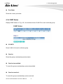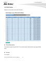
1
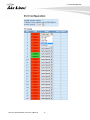
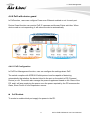
POE-GSH2004L-370 20-Port Gigabit + 4-Port UTP/SFP Combo Active PoE Web Smart Switch User’s Manual 1 Copyright and Disclaimer Copyright & Disclaimer No part of this publication may be reproduced in any form or by any means, whether electronic, mechanical, photocopying, or recording without the written consent of OvisLink Corp. OvisLink Corp. has made the best effort to ensure the accuracy of the information in this user’s guide. However, we are not liable for the inaccuracies or errors in this guide. Please use with caution. All information is subject to change without notice All Trademarks are properties of their respective holders. i AirLive POE-GSH2004L-370 User’s Manual Copyright and Disclaimer FCC Statement Federal Communication Commission Interference Statement This equipment has been tested and found to comply with the limits for a Class B digital device, pursuant to Part 15 of the FCC Rules. These limits are designed to provide reasonable protection against harmful interference in a residential installation. This equipment generates uses and can radiate radio frequency energy and, if not installed and used in accordance with the instructions, may cause harmful interference to radio communications. However, there is no guarantee that interference will not occur in a particular installation. If this equipment does cause harmful interference to radio or television reception, which can be determined by turning the equipment off and on, the user is encouraged to try to correct the interference by one of the following measures: Reorient or relocate the receiving antenna. Increase the separation between the equipment and receiver. Connect the equipment into an outlet on a circuit different from that to which the receiver is connected. Consult the dealer or an experienced radio/TV technician for help. FCC Caution Any changes or modifications not expressly approved by the party responsible for compliance could void the user's authority to operate this equipment. This device complies with Part 15 of the FCC Rules. Operation is subject to the following two conditions: (1) This device may not cause harmful interference, and (2) this device must accept any interference received, including interference that may cause undesired operation. For product available in the USA/Canada market, only channel 1~11 can be operated. Selection of other channels is not possible. This device and its antenna(s) must not be co-located or operation in conjunction with any other antenna or transmitter. IMPORTANT NOTE FCC Radiation Exposure Statement: This equipment complies with FCC radiation exposure limits set forth for an uncontrolled environment. This equipment should be installed and operated with minimum distance 20cm between the radiator & your body. AirLive SNMP-GSH2004L User’s Manual ii Table of Contents Table of Contents 1. Introduction .................................................................................................. 1 1.1 Overview ................................................................................................ 1 1.2 Guide to the Chapters ........................................................................... 2 1.3 Quick Setup ........................................................................................... 3 1.4 Installation Steps ................................................................................... 4 2. Installation of the Switch ............................................................................ 7 2.1 Unpack the Package ............................................................................. 7 2.2 Hardware Overview ............................................................................... 8 2.3 Installation Site Preparation ................................................................ 10 2.4 Rack Mounting ..................................................................................... 10 2.5 Desktop Installation ............................................................................. 12 2.6 Cabling Requirements ......................................................................... 12 2.7 Connecting to Power ........................................................................... 13 2.8 Reset to Default ................................................................................... 14 3. LED Indicators............................................................................................ 15 3.1 Comprehensive LEDs ......................................................................... 15 3.2 LED Table ............................................................................................ 15 4. Web Management ...................................................................................... 16 4.1 Setup your computer for Web management....................................... 16 4.2 Remote Management .......................................................................... 19 4.3 Get Into the Web management ........................................................... 21 4.4 Configuration ....................................................................................... 22 4.4.1 System Information................................................................................... 23 iii AirLive POE-GSH2004L-370 User’s Manual Table of Contents 4.4.2 Ports Configuration ................................................................................... 27 4.4.3 VLAN Mode Configuration ........................................................................ 30 4.4.4 VLAN Group Configuration ....................................................................... 31 4.4.5 VLAN Isolation .......................................................................................... 36 4.4.6 PoE with device guard .............................................................................. 37 4.4.7 Aggregation .............................................................................................. 41 4.4.8 RSTP........................................................................................................ 42 4.4.9 IGMP Snooping ........................................................................................ 44 4.4.10 Mirroring ................................................................................................. 45 4.4.11 QoS ........................................................................................................ 47 4.4.12 Loop Detection ....................................................................................... 50 4.4.13 Broadcast Strom Protection .................................................................... 51 4.4.14 SNMP ..................................................................................................... 54 4.5 Monitoring ............................................................................................ 56 4.5.1 Statistics Overview ................................................................................... 56 4.5.2 Detailed Statistics ..................................................................................... 57 4.5.3 RSTP Status ............................................................................................. 63 4.5.4 IGMP Status ............................................................................................. 66 4.5.5 PoE Status................................................................................................ 68 4.5.6 Ping .......................................................................................................... 70 4.6 Maintenance ........................................................................................ 73 4.6.1 Warm Restart ........................................................................................... 73 4.6.2 Factory Default ......................................................................................... 73 4.6.3 Software Upgrade..................................................................................... 74 4.6.4 Configuration File Transfer ....................................................................... 74 4.6.5 Logout ...................................................................................................... 75 Appendix A: Product Specifications ........................................................... 76 Appendix B: Troubleshooting ...................................................................... 80 AirLive SNMP-GSH2004L User’s Manual iv 1. Introduction 1 1. Introduction 1.1 Overview The POE-GSH2004L-370 is a Power Control POE Web Smart Switch, and total power is 370W. This Switch is a standard switch that meets all IEEE 802.3/u/x/z Gigabit, Fast Ethernet specifications. The switch has 20 10/100/1000Mbps TP ports and 4 Gigabit TP/SFP transceiver slots; it supports http and SNMP interface for switch management. The network administrator can logon the switch to monitor, configure and control each port’s activity. In addition, the switch implements the QoS (Quality of Service), VLAN, and Trunking. It is suitable for office application. Others the switch increase support the Power saving for reduce the power consumption with "ActiPHY Power Management" and "PerfectReach Power Management" two technique. It could efficient saving the switch power with auto detect the client idle and cable length to provide different power. These 24 10/100/1000Mbps RJ-45 support the IEEE 802.3at PoE protocol. Each port and transmit a maximum power 30 watts. User can also enable or disable power supply on PoE ports from UI. In this switch, Port 21, 22, 23, 24 includes two types of media --- TP and SFP Fiber (LC); these ports supports 10/100/1000Mbps TP or 100/1000Mbps SFP Fiber with auto-detected function. 1000Mbps SFP Fiber transceiver is used for high speed connection expansion. 1 AirLive POE-GSH2004L-370 User’s Manual 1. Introduction - 1000Mbps LC, Multi-Mode, SFP Fiber transceiver - 1000Mbps LC, Single-Mode, SFP Fiber transceiver, 10km - 1000Mbps LC, Single-Mode, SFP Fiber transceiver, 30km - 1000Mbps LC, Single-Mode, SFP Fiber transceiver, 50km - 100Mbps LC, Multi-Mode, SFP Fiber transceiver, 2km - 100Mbps LC, Single-Mode, SFP Fiber transceiver, 30km This user’s manual will help you to uncover most functions of the POE-GSH2004L-370 with step-by-step instructions presented by high quality illustrations. Thank you for choosing OvisLink’s product. Notice This switch is using 48V 802.3at PoE standard. It does not work with passive PoE. Do not connect with passive PoE devices When plug in the SFP module, the device will activate mini-GBIC, and the RJ45 port will be disabled. 1.2 Guide to the Chapters Chapter 1: Introduction and Quick Setup guide. All the essential information including IP Address and Password information are in the Quick Setup section. Chapter 2: Detail installation instruction. Chapter 3: LED indicators Chapter 4: Detail information on Web management including how to setup remote management. AirLive POE-GSH2004L-370 User’s Manual 2 1. Introduction 1.3 Quick Setup This section provides the essential information for experienced users to operate the switch immediately. For detailed installation instruction, please see chapter 2 for more information. Power-On the switch The POE-GSH2004L-370 has a built-in power supply to operate with 100 ~ 240V AC, 50 ~ 60Hz power source. The AC power cord connector is located at the rear of the unit and the On/Off switch is next to the connector. After the Switch is powered on, it will perform “self-diagnostic” test. This process takes about 5 seconds to complete. Important Information The default IP address: 192.168.2.1 The default password is airlive LED Table LED System Color/Status Green Description Power on 10/100/1000Ethernet TP Port 1 to 24 LED Green On Link Up Green Blinking Data activating Green On Link 1000Mbps SPD Yellow On Link 10/100Mbps 1000SX/LX Gigabit Fiber Port 21,22,23,24 LED Green On Link Up Link/ ACT Green Blinking Data activating Green On Link 1000Mbps SPD Yellow On Link 100Mbps PoE Link/ ACT PoE Green PoE connecting 3 AirLive POE-GSH2004L-370 User’s Manual 1. Introduction 1.4 Installation Steps This section lists the installation procedures in steps. Each step’s instruction is thoroughly explained in the subsequent sections of following chapter. Step1. Connect your device's PoE port to the switch's POE port (see Figure A). AirLive POE-GSH2004L-370 User’s Manual 4 1. Introduction Step2. If you are using a 802.3at compliant splitter with the switch, please install it according to Figure B. Step3. Your PoE device should get the power from the switch now. If you want to change settings via web management. Please follow the instructions below. Step4. If you want to install the switch on the 19" rack, please install the mounting kit according to Figure C. Step5. Set your PC's IP address to 192.168.2.50. 5 AirLive POE-GSH2004L-370 User’s Manual 1. Introduction Step6. Open your web browser and enter "192.168.2.1" to get into the switch's web management. Step7. Enter "airlive" for password. Step8. If you want to install the switch on the 19" rack, please install the mounting kit. Step9. Please see the following chapters for further configurations. AirLive POE-GSH2004L-370 User’s Manual 6 2. Installation of the Switch 2 2. Installation of the Switch This chapter provides the detailed instructions for installation of the switch. For concise installation instruction, the previous chapter’s “Quick Setup” section provides all the important information including IP address, password, and LED table for user’s reference. 2.1 Unpack the Package Before you begin the installation of POE-GSH2004L-370 Web smart Switch, make sure that you have all the necessary accessories that come with your package. Follow the steps below to unpack your package contents: 1. Clear out an adequate space to unpack the package carton. 2. Open the package carton and take out the contents carefully. 3. Put back all the shipping materials such as plastic bag, padding and linings into the package carton and save them for future transport need. After unpacking and taking out the entire package contents, you should check whether you have got the following items: POE-GSH2004L-370 One AC Power Cord Quick Install Guide Support CD-ROM (The PDF version of this User’s Manual can be found within CD) One Pair Rack-mount Kit + 8 Screws If any of these above items is missing or damaged, please contact your local dealer for replacement. 7 AirLive POE-GSH2004L-370 User’s Manual 2. Installation of the Switch 2.2 Hardware Overview 2.2.1 Front Panel The front panel of the web smart switch consists of 24 10/100/1000M Base-TX RJ-45 ports and 4 100/1000M Combo SFP ports. The LED Indicators are also located on the front panel. LED Indicators: Comprehensive LED indicators display the status of the switch and the network (see the LED Indicators chapter below). 1000BASE-T Gigabit Ethernet Ports (Port 1~24) The Switch four Gigabit twisted pair ports, supported auto negotiable 10/100/1000Mbps and auto MDI/MDIX crossover detection function, this function gives true “plug and play” capability, just need to plug-in the network cable to the hub directly and don’t care if the end node is NIC (Network Interface Card) or switch and hub. These ports can operate in half-duplex mode for 10/100Mbps and full- duplex mode for 10/100/1000Mbps. 24 10/100/1000Mbps RJ-45 ports are PoE enable ports. These PoE ports will be automatically activated when a compatible terminal is identified, and the PoE port will supply power to the connected PoE device. AirLive POE-GSH2004L-370 User’s Manual 8 2. Installation of the Switch For legacy devices that are not yet compatible, the PoE port will not offer the power to these devices. This feature allows users to freely and safely mix legacy and Power over Ethernet compatible devices on their network. Combo SFP Ports (Port 21~24) The Switch is equipped with four combo SFP ports, supported optional 1000BASE-SX/LX SFP module. The 1000BASE-T port 21~24 are the same ports with the SFP port 21~24, when plug in the SFP module, the device will activate SFP, and the RJ45 port will be disabled. ※Note: When the port was set to “Forced Mode”, the Auto MDI/MDIX will be disabled. Mode button: The Mode button is to change the LED’s status to Link/Act or Speed, and reset all the setting back to the factory default by pressing the mode button for 10 seconds. ※ Note: Be sure that you recorded the setting of your device; else all the setting will be erased when pressing the “Mode” (reset) button 10 seconds. 2.2.2 Rear Panel The 3-pronged power plug and on/off switch are placed at the rear panel of the switch right side shown as below. 9 AirLive POE-GSH2004L-370 User’s Manual 2. Installation of the Switch 2.3 Installation Site Preparation You can mount POE-GSH2004L-370 either on desktop or on a 19-inch rack. If you plan to mount the switch on desktop, please choose a steady, level surface in a well-ventilated area that is free from excessive dust. In any case, the installation site chosen for your switch has to comply with the following requirements: The surface where you want to mount the switch must be able to sustain at least 2.4kg. Do not place heavy objects (more than 3kg) on top of the switch. The location must preferably be free from excessive dust, away from heat vent, hot-air exhaust and direct sunlight. The switch should not be placed near large electric motors or other strong electromagnetic sources. As a reference, the strength of the electromagnetic field on site should not exceed the (RFC) standards for IEC 801-3, Level 2(3V/M) field strength. The air temperature in the location should be within a range of 32 to 122 °F (0 to 50°C). The relative humidity in the location should not exceed 90% non-condensing humidity. The distance between the RJ-45 port and the standard network interface should not exceed 100 meters. Adequate space should be allowed in front of all the ports, so that each port is easily accessible for cable connections. Leave at least 10cm(4 inch) of space around the switch to allow heating dissipation 2.4 Rack Mounting The POE-GSH2004L-370 can be mounted on a standard size 19-inch rack, which can in turn be placed in a wiring closet with other equipment. Before you can mount the switch on the rack, first you must attach the mounting brackets on both sides of the switch with screws, and then mount it as a unit on the rack. To mount the unit on a rack, please follow the steps below: Step 1. First, align the holes on the bracket with the holes on both side of the switch. Step 2. Insert screws into the holes and then fasten the bracket on one side of the switch with a screwdriver. AirLive POE-GSH2004L-370 User’s Manual 10 2. Installation of the Switch Step 3. Repeat Step 1 and 2 to fasten the bracket on the other side of the switch. Step 4. Mount the unit on the rack and align the notches on both brackets with mounting holes on the rack, and then secure the unit with suitable screws. Fastening the brackets on the switch Attaching the Switch to a 19-inch rack 11 AirLive POE-GSH2004L-370 User’s Manual 2. Installation of the Switch 2.5 Desktop Installation The POE-GSH2004L-370 has four rubber pads attached on each corner of its underside. These pads serve as cushioning against vibration and prevent the switch from sliding off its position. They also allow adequate ventilation space when you place the switch on top of another device. Desktop installation The location you choose to install your switch and the way you configure your network may greatly affect its performance. Please see the previous section for “installation site” preparation. Do not place more than 1.5kg (6.6lbs) of weight on the top of the switch. Leave at least 10cm of space around the switch to allow proper heating dissipation. 2.6 Cabling Requirements For 100BASE-TX and 1000Base-T ports The 24 RJ-45 station ports and the 1000Base-T ports of the optional Gigabit-Copper module require Cat. 5 twisted-pair UTP/STP cable for connection. When configuring within the 10/100/1000BASE-T cabling architecture, the cable distance should be within 100m. The following table summarizes the cable requirement for 10/100/1000BASE-TX connection: AirLive POE-GSH2004L-370 User’s Manual 12 2. Installation of the Switch 10BASE-T 100 ohm Category 3, 4, 5 UTP/STP cable 100BASE-TX 100 ohm Category 5 UTP/STP cable 1000BASE-T 100 ohm Category 5 UTP/STP cable or better (CAT 5E recommended) Auto MDI/MDI-X function The POE-GSH2004L-370 is equipped with Auto-MDI/MDI-X function, which allows you to use straight-through cable even when connecting to another switch/hub. Simply use the straight-through cable for all types of 10/100BASE-TX connections, either to a PC or to a networking device such as other hub or switch. Specification Connection 10 /100Base-TX and 1000Base-TPorts Interface Cable to Use To an end station To a hub/switch Maximum Distance RJ-45 Straight-through twisted-pair cable Straight-through twisted-pair cable 100 meters Table 2-2 Cabling type for 10/100BASE-TX and 1000Base-T 2.7 Connecting to Power POE-GSH2004L-370 features a universal auto-select power supply unit, which allows a power connection to a wide range of input voltages from 100 to 240VAC @ 50 ~ 60Hz. To establish its power connection, simply plug the female end of the power cord into the power connector on the rear of the switch and the male end of the power cord into a suitable power outlet. Once you have correctly plugged in the power, you can then turn on the Power Switch to activate the switch. 13 AirLive POE-GSH2004L-370 User’s Manual 2. Installation of the Switch 2.8 Reset to Default When you forgot your IP or password, please use the mode (reset) button for the factory default setting. Please take the following steps to reset the Web Smart Switch back to the original default: Step 1. Turn on the POE-GSH2004L-370. Step 2. Press and hold the mode (reset) button continuously for 10 seconds and release the mode (reset) button. Step 3. The switch will reboot for 30 seconds and the configuration of switch will back to the default setting. Key in the user ID and the password to pass the authentication; the default ID and Password is as below, IP Address: 192.168.2.1 Password: airlive AirLive POE-GSH2004L-370 User’s Manual 14 3. LED Indicators 3 3. LED Indicators Before connecting any network device to POE-GSH2004L-370, you should take a few minutes to look over this chapter and get familiar with the front panel LED indicators of your Switch. 3.1 Comprehensive LEDs 3.2 LED Table LED Power Color/Status Green Description Power on 10/100/1000Ethernet TP Port 1 to 24 LED Green On Link Up Green Blinking Data activating Green On Link 1000Mbps SPD Yellow On Link 10/100Mbps 1000SX/LX Gigabit Fiber Port 21,22,23,24 LED Link/ ACT Link/ ACT SPD Green On Green Blinking Green On Yellow On Link Up Data activating Link 1000Mbps Link 100Mbps Green PoE connecting PoE PoE 15 AirLive POE-GSH2004L-370 User’s Manual 4. Web Management 4 4. Web Management The POE-GSH2004L-370 can be configured by web based interface, including System Information, Ports Configuration, VLAN setting, Aggregation, QoS setting, PoE, IGMP Snooping, Mirroring, SNMP, Loop Detection, Broadcast Strom, configuration/ backup/recovery, log out, and so on. The device based smart switch supports main stream browsers, such as IE, Firefox and Chrome…etc to configure the device function. All functions are illustrated below. 4.1 Setup your computer for Web management The Concept of Subnet Under the TCP/IP environment, network devices must be on the same subnet in order to see each other. This means before you can configure the switch through web browser, you must set your computer to the same subnet as the switch. For two network devices to be on the same subnet, they must have the following 2 criteria: Their IP address must be on the same subnet. For example, if one IP address is 192.168.2.1. The other’s IP address must be 192.168.2.x (x is any number between 2 and 254) for Class C subnet. To find out the IP address information for your computer. Under WinXP/Vista/Win7/Win8, please open Command Line window and type “ipconfig”. They must have the same subnet mask. For example, if one machine is 255.255.255.0. The other machine must also set to the same 255.255.255.0 mask. AirLive POE-GSH2004L-370 User’s Manual 16 4. Web Management Configure your computer’s IP Before accessing the switch through web browser, please follow the instruction below to configure your computer’s IP to the same subnet as the switch. If your switch’s IP has not been changed, it should have the following factory default value: The switch’s Default IP IP Address: 192.168.2.1 Subnet Mask: 255.255.255.0 Now if your computer’s IP is not in the same subnet as the switch, please follow the steps below to change the computer’s IP: STEP 3 STEP 2 STEP 4 STEP 1 Figure 4-1 Manual IP setting 17 AirLive POE-GSH2004L-370 User’s Manual 4. Web Management Step 1. Double click on the network connection status icon on the task bar. This should bring up a window showing the status of the current network connection. If there is no network status icon on the task bar, please go to the “Start -> Settings -> Network -> Local Connection” of the task bar’s Start menu. Step 2. Clock on the “property” icon. Step 3. Double click on the “Internet Protocol (TCP/IP) Step 4. Click on “Use the following IP address” button and enter the computer’s address manually. This IP address must be on the same subnet as the switch but different from the switch’s IP. Please make sure the IP is not used by other network device. If the switch’s IP address is of factory’s default value. We recommend enter the following for computer’s IP: IP Address: 192.168.2.50 Subnet Mask: 255.255.255.0 Gateway: 192.168.2.1 Click “Ok” after finish entering the IP. ※ Note1: The POE-GSH2004L-370 has DHCP client ability. This allows DHCP server (or router) to assign IP automatically. However, we do not recommend turning on the DHCP client because the DHCP server assign the IP randomly. The DHCP client should be used only when connecting directly to Cable Modem (for remote management) whose service provider uses DHCP for IP assignment. Now, you will be able to access the switch by typing in the switch’s IP address on the web browser. AirLive POE-GSH2004L-370 User’s Manual 18 4. Web Management 4.2 Remote Management In this section, you will learn how to setup your computer and the router for remote web management. Remote management allows MIS to manage a switch from outside of the switch’s IP domain or from Internet. Depending on the type of Internet connection you have, there are two ways to setup the switch to be available through Internet. Direct Connection to Internet If you have a fixed IP xDSL account or cable modem account, and there is no router in the network, you can connect your switch directly to Internet via xDSL modem/Cable Modem. However, this method is not recommended as the LAN will be directly exposed to the Internet. Fixed IP: If your ISP has assigned you a fixed IP. Please go to the Switch’s IP configuration and enter the IP address, Subnet Mask, and Gateway information offered by your ISP. If your ADSL connection is PPPoE or PPTP type, you have to connect through a router for remote management. Cable Modem: If your Cable service provider uses DHCP for IP assignment, please turn on the DHCP function under IP configuration. Make sure there is no DHCP server in the network. Then the Cable provider will assign the switch with a IP and Gateway. Go to the console port management to find out what IP has been assigned to the switch. When the configuration is finished, the Remote PC can access the switch by typing the switch’s IP address on the web browser. 19 AirLive POE-GSH2004L-370 User’s Manual 4. Web Management Connect through Broadband Router If you have an IP sharing router in the network, you can open a virtual server on the router to allow the switch to be managed through Internet. This method is more recommended as the broadband router provides natural firewall protector from hackers. In the diagram above, the router has the WAN (given by the ISP) port IP address “201.100.1.5” and LAN port address “192.168.0.254”. The switch’s IP is “192.168.0.200”. Please follow the instruction below to setup the router and switch for remote access: On the Switch On the IP setting, set the gateway to Router’s LAN port address 192.168.0.254. Please make sure the subnet mask is the same as the router’s. On the Router Go to router’s Virtual Server setting and open the Web port (TCP Port 80) to the switch’s IP address 192.168.0.200. If your router require enter the beginning and ending Port (from PortX to PortX), enter 80 for both. Now the Remote PC will be able to access your switch by entering “201.100.1.5” in the Web browser’s address field. AirLive POE-GSH2004L-370 User’s Manual 20 4. Web Management 4.3 Get Into the Web management After you have properly configured the computer and switch’s IP, you can get into the web management by the following steps: Step 1. Open the Internet Explorer Step 2. Enter the switch’s IP address in the Address field and press enter. Step 3. When prompt for and Password, enter the following information: Password: airlive You should see the following welcome screen after the process is completed: 21 AirLive POE-GSH2004L-370 User’s Manual 4. Web Management Menu Bar On the left side, the main menu tree for web is listed in the page. According to the function name in boldface, all functions can be divided into three parts, including “Configuration”, “Monitoring” and “Maintenance”. The functions of each folder are described in its corresponded section respectively. As to the function names in normal type are the sub-functions. When clicking it, the function is performed. The following list is the main function tree for web user interface. Top Switch Image The switch’s image on the upper portion of the screen gives the quick overview of the port connection status. When a port is plugged in, the switch’s image will show a “plug” on the corresponding port. 4.4 Configuration Configuration includes the following functions: System Information Ports Configuration VLAN Mode Configuration VLAN Group Configuration VLAN Isolation PoE Aggregation RSTP IGMP Snooping Mirroring QoS Loop Detection Broadcast Strom Protection SNMP In the following sessions, we will talk in detail about the management functions under the Configuration menu. AirLive POE-GSH2004L-370 User’s Manual 22 4. Web Management 4.4.1 System Information System configuration is one of the most important functions. Without a proper setting, network administrator would not be able to manage the device. The switch supports manual IP address setting. 23 AirLive POE-GSH2004L-370 User’s Manual 4. Web Management System Description: The simple description of this switch. Firmware Version: The firmware version of this switch. Hardware Version: The hardware version of this switch. MAC Address: It is the Ethernet MAC address of the management agent in this switch. Serial Number: The serial number is assigned by the manufacturer. Temperature: Show the Temperature of this switch. Voltage: Show the Voltage of this switch. Active IP Address: Show the active IP address of this switch. AirLive POE-GSH2004L-370 User’s Manual 24 4. Web Management Active Subnet Mask: Show the active subnet mask of this switch. Active Gateway: Show the active gateway of this switch. DHCP Server: Show the IP address of the DHCP server. Default: 0.0.0.0 Lease Time Left: Show the lease time left of DHCP client. Device Name: Set a special name for this switch. Up to 16 characters are allowed in this parameter. Any alphanumeric character and null are acceptable. Default: POE-GSH2004L-370 System Contact: Set a special System Contact name for this switch. Any alphanumeric character and null are acceptable. Default: Ovislink 25 AirLive POE-GSH2004L-370 User’s Manual 4. Web Management System Location: Set a special System Location name for this switch. Any alphanumeric character and null are acceptable. Default: Taiwan DHCP Enabled: Enable DHCP snooping, Just tick the check box ( ) to enable it. Default: disable Fallback IP Address: Manually assign the IP address that the network is using. Default: 192.168.2.1 Fallback Subnet Mask: Assign the subnet mask to the IP address. Default: 255.255.255.0 Fallback Gateway: Assign the network gateway for industrial switch. Default: 192.168.2.254 AirLive POE-GSH2004L-370 User’s Manual 26 4. Web Management Management VLAN: Show the management VLAN number. Password: Set a password for this switch. Up to 16 characters are allowed in this parameter. Any alphanumeric character is acceptable. Default: airlive Inactivity Timeout(secs): Set the auto-logout timer. The valid value is 0 ~ 60 in the unit of minute and a decimal point is not allowed. The value 0 means auto-logout timer is disabled. Default: 600 4.4.2 Ports Configuration Port Configuration is applied for the settings of the ports on the switch. By this function, you can set or reset the values for Mode and Flow Control. Others you could set the power saving mode for switch power consumption. 27 AirLive POE-GSH2004L-370 User’s Manual 4. Web Management AirLive POE-GSH2004L-370 User’s Manual 28 4. Web Management Enable Jumbo Frames: This function support jumbo frames of up to 9600 bytes, Just tick the check box ( enable it. ) to Default: disable Perfect Reach/Power Saving Mode: This function supports Power Saving and perfect Reach, Just select with the Full/ Link-up/ Link-down/ Disable Default: disable Link: Show link status of this port. 29 AirLive POE-GSH2004L-370 User’s Manual 4. Web Management Mode: Set the speed and duplex of the port. If the media is 1Gbps fiber, there are three modes to choose: Auto Speed, 1000 Full and Disable. If the media is TP, the Speed/Duplex is comprised of the combination of speed mode, 10/100/1000Mbps, and duplex mode, full duplex and half duplex. In Auto Speed mode, no default value. In Forced mode, default value depends on your setting. Flow Control: You can Just tick the check box ( ) to enable flow control. If flow control is set Enable, both parties can send PAUSE frame to the transmitting device(s) if the receiving port is too busy to handle. When it is set Disable, there will be no flow control in the port. It drops the packet if too much to handle. Default: Disable 4.4.3 VLAN Mode Configuration Web Smart Switch supports Port-based VLAN and Tag-based VLAN (802.1q). Its VLAN mode supports 10 active VLANs and the available VLAN ID range is from 1~4094. VLAN configuration is used to divide a LAN into smaller ones. With proper configuration, you can gain not only improved security and increased performance, but also save a lot of VLAN management effort. The VLAN Mode Selection function includes two modes: Port-based, Tag-based. AirLive POE-GSH2004L-370 User’s Manual 30 4. Web Management VLAN mode: Port-based: Port-based VLAN is defined by port. Any packet coming in or outgoing from any one port of a port-based VLAN will be accepted. No filtering criterion applies in port-based VLAN. The only criterion is the physical port you connect to. For example, for a port-based VLAN named PVLAN-1 contains port members Port 1&2&3&4. If you are on the port 1, you can communicate with port 2&3&4. If you are on the port 5, then you cannot talk to them. Each port-based VLAN you built up must be assigned a group name. This switch can support up to maximal 10 port-based VLAN groups. Tag-based: Tag-based VLAN identifies its member by VID. This is quite different from port-based VLAN. If there are any more rules in ingress filtering list or egress filtering list, the packet will be screened with more filtering criteria to determine if it can be forwarded. The switch supports supplement of 802.1q. For more details, please see the section VLAN in Chapter 3. Each tag-based VLAN you built up must be assigned VLAN name and VLAN ID. Valid VLAN ID is 1-4094. User can create total up to 10 Tag VLAN groups. 4.4.4 VLAN Group Configuration Tag based VLAN mode The VLAN membership configuration for the selected switch can be monitored and modified here. Up to 4094 VLANs are supported. This page allows for adding and deleting VLANs as well as adding and deleting port members of each VLAN. 31 AirLive POE-GSH2004L-370 User’s Manual 4. Web Management AirLive POE-GSH2004L-370 User’s Manual 32 4. Web Management VID: VLAN identifier. Each tag-based VLAN group has a unique VID. It appears only in tag-based mode. Member: In modify function this is used to enable or disable if a port is a member of the new added VLAN, “Enable” means it is a member of the VLAN. Just tick the check box ( ) beside the port x to enable it. 33 AirLive POE-GSH2004L-370 User’s Manual 4. Web Management Port: Port number. VLAN aware Enabled: Discard other VLAN group packets, only forward this port joined VLAN group packets. Packet Type: All: Forward all tagged and untagged packets. Tagged Only: Forward tagged packets only and discard untagged packets. Pvid: This PVID range will be 1-4094. Before you set a number x as PVID, you have to create a Tag-based VLAN with VID x. For example, if port x receives an untagged packet, the switch will apply the PVID(assume as VID y) of port x to tag this packet, the packet then will be forwarded as the tagged packet with VID Port-based VLAN mode AirLive POE-GSH2004L-370 User’s Manual 34 4. Web Management ID (Group ID): When you want to edit a VLAN group, you must select the Group ID field. Then, you will enter Tag Base VLAN Group Setting or Port Base VLAN Group Setting page, which depends on your VLAN mode selection. Member: In modify function this is used to enable or disable if a port is a member of the new added VLAN, “Enable” means it is a member of the VLAN. Just tick the check box ( ) beside the port x to enable it. Add Group: Create a new port-based VLAN or tag-based VLAN, which depends on the VLAN mode you choose in VLAN mode function. Delete Group: Just tick the check box ( ) beside the ID, then press the <Delete> button to delete the group. 35 AirLive POE-GSH2004L-370 User’s Manual 4. Web Management 4.4.5 VLAN Isolation Port Isolation provides for an apparatus and method to isolate ports on layer 2 switches on the same VLAN to restrict traffic flow. The apparatus comprises a switch having said plurality of ports, each port configured as a protected port or a non-protected port. An address table memory stores an address table having a destination address and port number pair. A forwarding map generator generates a forwarding map which is responsive to a destination address of a data packet. The method for isolating ports on a layer 2 switch comprises configuring each of the ports on the layer 2 switch as a protected port or a non-protected port. A destination address on a data packet is matched with a physical address on said layer 2 switch and a forwarding map is generated for the data packet based upon the destination address on the data packet. The data packet is then sent to the plurality of ports pursuant to the forwarding map generated based upon whether the ingress port was configured as a protected or non-protected port. This page is used for enabling or disabling port isolation on ports in a Private VLAN.A port member of a VLAN can be isolated to other isolated ports on the same VLAN and Private VLAN. Port Members: A check box is provided for each port of a private VLAN. When checked, port isolation is enabled on that port. When unchecked, port isolation is disabled on that port. By default, port isolation is disabled on all ports. AirLive POE-GSH2004L-370 User’s Manual 36 4. Web Management 4.4.6 PoE with device guard In PoE section, users can configure Power over Ethernet enabled or not for each port. Device Guard function can monitor PoE IP cameras and Access Points activities. When device crash or not responding, it will reboot the device automatically. 4.4.6.1 PoE Configuration In PoE Port Management function, user can configure the settings about PoE. The switch complies with IEEE 802.3af/at protocol and be capable of detecting automatically that whether the device linked to the port on the switch is PD (Powered Device) or not. The switch also manage the power supplement based on the Class of the PD, and it will stop supplying the power once the power required by the PD excesses the Class, Short Circuit or over temperature occurs. PoE Enabled: To evoke to enable which port supply the power to the PD. 37 AirLive POE-GSH2004L-370 User’s Manual 4. Web Management Priority: Three options are offered for the user to choose, including Low, Medium, High and Critical. Default is Low. The switch will stop supplying the power to the port based on the order of the priority Low→Medium→High→Critical in case total power required by all PDs linked to the switch excesses the power limit. As the ports have the same priority, then the switch will cease the power supplement from the port with the highest port id (12→1). Allocation (W): The power is consumed by the port. Detection: 4-Point, Legacy, Both. Delay time: The delay time of PoE, 0~300seconds, default is 0. Reset: Reset the PoE Port which is select. AirLive POE-GSH2004L-370 User’s Manual 38 4. Web Management 4.4.6.2 Device Guard There are two device guard methods to guard your PoE devices. One is guard Packet the other is guard IP. When Guard Pkts is enabled, the switch will do the failure action if there is no any incoming packet at each port for a period. When the IP is set in the guard IP , the switch will try to ping the IP , if the IP is not reply , the switch will do the failure action. 39 AirLive POE-GSH2004L-370 User’s Manual 4. Web Management Guard Pkts To Enable the Guard pkts function. Guard IP address To Enable the Guard IP address function, please key in IP address of the PoE device. The switch will ping the devices, if there is no reply. The switch will do the failure action. Please remember that do not disable the Ping echo function in your PoE devices. Interval time To set the interval time. The switch will ping the IP after Interval time. Retry time To set that how many time that the switch will retry when the Pin is not reply. Failure action To set the action when PoE device is detected that it is failure. There are two opinion, nothing and reboot. Reboot To set how many time this switch will wait, when reboot is required by device guard. AirLive POE-GSH2004L-370 User’s Manual 40 4. Web Management 4.4.7 Aggregation The Aggregation (Port Trunking) Configuration is used to configure the settings of Link Aggregation. You can bundle ports by same speed, MAC, and full duplex to be a single logical port, thus the logical port can aggregate the bandwidth of these ports. This means you can apply your current Ethernet equipment to build the bandwidth aggregation. For example, if three Fast Ethernet ports are aggregated into a logical port, then this logical port’s bandwidth would be as three times high as a single Fast Ethernet ports. Normal: Set up the ports that do not join any aggregation trunking group. Group 1~8: Group the ports you choose together. Up to 12 ports can be selected for each group. 41 AirLive POE-GSH2004L-370 User’s Manual 4. Web Management 4.4.8 RSTP The switch supports IEEE 802.1D-2004 RSTP protocol, the RSTP protocol can backward compatible to legacy Spanning Tree Protocol (STP) and 802.1w Rapid Spanning Tree Protocol (RSTP). Force version: STP and RSTP. Select the STP version you want to enabled. System Priority This parameter configures the spanning tree priority globally for this switch. The device with the highest priority becomes the STP root device. However, if all devices have the same priority, the device with the lowest MAC address will then become the root device. Number between 0 - 61440 in increments of 4096. Therefore, there are 16 distinct values. Hello Time Interval (in seconds) at which the root device transmits a configuration message (BPDU frame). Number between 1-10 (default is 2). Max Age The maximum time (in seconds) a device can wait without receiving a configuration message before attempting to reconfigure. That also means the maximum life time for a BPDU frame. Number between 6-40 (default is 20). Forward Delay The maximum time (in seconds) the root device will wait before changing states (i.e., discarding to learning to forwarding). Number between 4–30 (default is 15) AirLive POE-GSH2004L-370 User’s Manual 42 4. Web Management 43 AirLive POE-GSH2004L-370 User’s Manual 4. Web Management 4.4.9 IGMP Snooping IGMP Snooping lets administrators configure a switch to constrain multicast traffic by listening to Internet Group Management Protocol (IGMP). IGMP Enabled: Just tick the check box ( ) to enable this function. Default: disable Router Ports: Just tick the check box ( button to start up. ) beside the port x to enable router ports, then press the <Apply> Default: none AirLive POE-GSH2004L-370 User’s Manual 44 4. Web Management Unregistered IGMP Flooding enabled: Just tick the check box ( ) to enable this function. Default: enable VLAN ID: At the IGMP Enable mode being selected, it will list the VLAN ID number. IGMP Snooping Enabled: After IGMP Enabled function start up then user can tick the check box ( ) to enable this function. Default: enable IGMP Querying Enabled: After IGMP Enabled function start up then user can tick the check box ( ) to enable this function. Default: enable 4.4.10 Mirroring Mirror Configuration is provided to monitor the traffic in the network. This switch supports one-port mirror multi-ports. For example, we assume that Port A and Port B are Source Ports, and Port C is Mirror Port respectively, thus, the traffic passing through Port A and Port B will be copied to Port C for monitor purpose. 45 AirLive POE-GSH2004L-370 User’s Manual 4. Web Management Source Port: Set up the port for being monitored. Just tick the check box () beside the port x and valid port is Port 1~24. Mirror Port: Use the drop-down menu to select a mirror port. AirLive POE-GSH2004L-370 User’s Manual 46 4. Web Management 4.4.11 QoS The switch offers powerful QoS function. This function supports VLAN-tagged priority that can make precedence of 8 priorities, and DSCP (Differentiated Services Code Point) on Layer 3 of network framework. While setting QoS function, please select QoS Mode in drop-down menu at first. Then you can use 802.1p Priority and DSCP Priority functions. In this function, you can enable/disable QoS Mode and set Priority Control, such as: 802.1p and DSCP. The switch only supports Strict Priority. High priority queue is always passed first. 802.1p QoS Mode This function will affect the priority of VLAN tag. Based on priority of VLAN tag, it can arrange 0~7 priorities, priorities can map to 4 queues of the switch (low, normal, medium, high) and possess different bandwidth distribution according to your weight setting. 47 AirLive POE-GSH2004L-370 User’s Manual 4. Web Management Prioritize Traffic: Five Prioritize Traffic values are provided: Custom, All Low Priority, All Normal Priority, All Medium Priority, and All High Priority. The QoS setting would apply to all ports on the switch if one of the following values is selected: All Low Priority, All Normal Priority, All Medium Priority, or All High Priority. Port Number: When Custom is selected for Prioritize Traffic, you may assign specific Port Number for 802.1p Configuration. 802.1p Configuration: Each Priority can select any of Queue. In Default, Priority 0 is mapping to Queue normal, Priority 1 is mapping to Queue low, Priority 2 is mapping to Queue low, Priority 3 is mapping to Queue normal, Priority 4 is mapping to Queue medium, Priority 5 is mapping to Queue medium, Priority 6 is mapping to Queue high, and Priority 0 is mapping to Queue high. DSCP QoS Mode In the late 1990s, the IETF redefined the meaning of the 8-bit SERVICE TYPE field to accommodate a set of differentiated services (DS). Under the differentiated services interpretation, the first six bits comprise a codepoint, which is sometimes abbreviated DSCP, and the last two bits are left unused. DSCP can form total 64 (0~63) kinds of Traffic Class based on the arrangement of 6-bit field in DSCP of the IP packet. In the switch, user is allowed to set up these 64 kinds of Class that belong to any of queue (low,normal, medium, high). AirLive POE-GSH2004L-370 User’s Manual 48 4. Web Management Prioritize Traffic: Five Prioritize Traffic values are provided: Custom, All Low Priority, All Normal Priority, All Medium Priority, and All High Priority. The QoS setting would apply to all ports on the switch if one of the following values is selected: All Low Priority, All Normal Priority, All Medium Priority, or All High Priority. Port Number: When Custom is selected for Prioritize Traffic, you may assign specific Port Number for DSCP Configuration. DSCP Configuration: 64 kinds of priority traffic as mentioned above, user can set up any of Queue (low, normal, medium, high). In default, Priority 0~63 are mapping to Queue high. 49 AirLive POE-GSH2004L-370 User’s Manual 4. Web Management 4.4.12 Loop Detection The loop detection is used to detect the presence of traffic. When switch receives packet’s (looping detection frame) MAC address the same as oneself from port, show Loop detection happens. The port will be locked when it received the looping detection frames. If you want to resume the locked port, please find out the looping path and take off the looping path, then select “Unlock port” and click on “Apply” to turn on the locked ports. AirLive POE-GSH2004L-370 User’s Manual 50 4. Web Management Port: Local port number State: Show the status on the port. Protocol Enabled: Controls whether Loop Detection is enabled on this switch port. When Port No is chosen and enable port' s Loop detection, the port can detect loop happens and port will be Locked. If Loop did not happen, port maintains Unlocked. Unlock port: When ticking the port, port locked will be opened and turned into unlocked. If not ticking the port, Port maintains locked. 4.4.13 Broadcast Strom Protection When the broadcast packets received by the switch exceed the threshold configured, the port will be blocked for a period of time which can be set. After a configured time, the switch will detect whether the broadcast packets received on the port still exceed the threshold. If the broadcast traffic is still higher than, the port will be closed for a period of time again. If the broadcast traffic is under the threshold, the port will re-open and forward the packets normally. 51 AirLive POE-GSH2004L-370 User’s Manual 4. Web Management AirLive POE-GSH2004L-370 User’s Manual 52 4. Web Management Mode: Controls whether Broadcast Strom Protection is enabled (as a whole). Packet Per Second: It is a threshold. When the broadcast packet traffic in a second is higher than the threshold configured, the Broadcast Strom Protection enable . Unlock Time: The period (in seconds) for which a port will be kept disabled in the event of a loop is detected (and the port action is to shut down the port). State: Show the status on the port. Protocol Enabled: Controls whether Broadcast Strom Protection is enabled on this switch port. Unlock port: When ticking the port, port locked will be opened and turned into unlocked. If not ticking the port, Port maintains locked. 53 AirLive POE-GSH2004L-370 User’s Manual 4. Web Management 4.4.14 SNMP Any Network Management System (NMS) running the Simple Network Management Protocol (SNMP) can manage the Managed devices equipped with SNMP agent, provided that the Management Information Base (MIB) is installed correctly on the managed devices. It is a protocol used to govern the transfer of information between SNMP manager and agent and traverses the Object Identity (OID) of the management Information Base (MIB), described in the form of SMI syntax. SNMP agent is running on the switch to response the request issued by SNMP manager. Basically, it is passive except issuing the trap information. The switch supports a switch to turn on or off the SNMP agent. If you set the field SNMP “Enable”, SNMP agent will be started up. If the field SNMP is set “Disable”, SNMP agent will be de-activated, the related Community Name, Trap Host IP Address, Trap and all MIB counters will be ignored. This function is used to configure SNMP settings, community name, trap host and public traps as well as the throttle of SNMP. A SNMP manager must pass the authentication by identifying both community names, then it can access the MIB information of the target device. So, both parties must have the same community name. Once completing the setting, click <Apply> button, the setting takes effect. AirLive POE-GSH2004L-370 User’s Manual 54 4. Web Management SNMP enable: The term SNMP enable here is used for the activation or de-activation of SNMP. Default is “Disable”. Get/Set/Trap Community: Community name is used as password for authenticating if the requesting network management unit belongs to the same community group. If they both don’t have the same community name, they don’t belong to the same group. Hence, the requesting network management unit cannot access the device with different community name via SNMP protocol; If they both have the same community name, they can talk each other. Community name is user-definable with a maximum length of 15 characters and is case sensitive. There is not allowed to put any blank in the community name string. Any printable character is allowable. The community name for each function works independently. Each function has its own community name. Say, the community name for Read only works for Read function and can’t be applied to other function such as Write and Trap. Default SNMP function: Disable Default community name for Get: public Default community name for Set: private Default community name for Trap: public System Event: The System Event trap enable here is used for the “Cold Boot” or “Warm Boot” of system Event. Default is “Disable”. 55 AirLive POE-GSH2004L-370 User’s Manual 4. Web Management TP and Fiber Port Event: The TP and Fiber Port Event trap enable here is used for the “Link Up” or “Link Down” of system Event. Default is “Disable”. 4.5 Monitoring Monitoring includes the following functions: Statistics Overview Detailed Statistics IGMP Status PoE Status Ping 4.5.1 Statistics Overview The section describes to the Port statistics information and provides overview of general traffic statistics for all switch ports. AirLive POE-GSH2004L-370 User’s Manual 56 4. Web Management Tx/Rx Bytes: The number of received and transmitted bytes per port. Tx/Rx Frames: The number of received and transmitted frames per port. Tx/Rx Errors: The number of frames received in error and the number of incomplete transmissions per port. 4.5.2 Detailed Statistics Display the detailed counting number of each port’s traffic. In the Fig. 4-20, the window can show all counter information each port at one time. 57 AirLive POE-GSH2004L-370 User’s Manual 4. Web Management Rx Packets: The counting number of the packet received. RX Octets: Total received bytes. Rx High Priority Packets: Number of Rx packets classified as high priority. Rx Low Priority Packets: Number of Rx packets classified as low priority. Rx Broadcast: Show the counting number of the received broadcast packet. Rx Multicast: Show the counting number of the received multicast packet. Rx Broad- and Multicast: Show the counting number of the received broadcast with multicast packet. Rx Error Packets: Show the counting number of the received error packets. AirLive POE-GSH2004L-370 User’s Manual 58 4. Web Management Tx Packets: The counting number of the packet transmitted. Tx Octets: Total transmitted bytes. Tx High Priority Packets: Number of Tx packets classified as high priority. Tx Low Priority Packets: Number of Tx packets classified as low priority. Tx Broadcast: Show the counting number of the transmitted broadcast packet. Tx Multicast: Show the counting number of the transmitted multicast packet. Tx Broad- and Multicast: Show the counting number of the transmitted broadcast with multicast packet. Tx Error Packets: Show the counting number of the received error packets. 59 AirLive POE-GSH2004L-370 User’s Manual 4. Web Management Rx 64 Bytes: Number of 64-byte frames in good and bad packets received. Rx 65-127 Bytes: Number of 65 ~ 126-byte frames in good and bad packets received. Rx 128-255 Bytes: Number of 127 ~ 255-byte frames in good and bad packets received. Rx 256-511 Bytes: Number of 256 ~ 511-byte frames in good and bad packets received. Rx 512-1023 Bytes: Number of 512 ~ 1023-byte frames in good and bad packets received. Rx 1024-Bytes: Number of 1024-max_length-byte frames in good and bad packets received. Tx 64 Bytes: Number of 64-byte frames in good and bad packets transmitted. Tx 65-127 Bytes: Number of 65 ~ 126-byte frames in good and bad packets transmitted. AirLive POE-GSH2004L-370 User’s Manual 60 4. Web Management Tx 128-255 Bytes: Number of 127 ~ 255-byte frames in good and bad packets transmitted. Tx 256-511 Bytes: Number of 256 ~ 511-byte frames in good and bad packets transmitted. Tx 512-1023 Bytes: Number of 512 ~ 1023-byte frames in good and bad packets transmitted. Tx 1024-Bytes: Number of 1024-max_length-byte frames in good and bad packets transmitted. Rx CRC/Alignment: Number of Alignment errors and CRC error packets received. Rx Undersize: Number of short frames (<64 Bytes) with valid CRC. Rx Oversize: Number of long frames(according to max_length register) with valid CRC. Rx Fragments: Number of short frames (< 64 bytes) with invalid CRC. 61 AirLive POE-GSH2004L-370 User’s Manual 4. Web Management Rx Jabber: Number of long frames (according to max_length register) with invalid CRC. Rx Drops: Frames dropped due to the lack of receiving buffer. Tx Collisions: Number of collisions transmitting frames experienced. Tx Drops: Number of frames dropped due to excessive collision, late collision, or frame aging. Tx Overflow: Number of frames dropped due to the lack of transmitting buffer. AirLive POE-GSH2004L-370 User’s Manual 62 4. Web Management 4.5.3 RSTP Status RSTP VLAN Bridge Overview Bridge Id: Show this switch’s current bridge priority setting and bridge ID which stands for the MAC address of this switch. Bridge Priority: This parameter configures the spanning tree priority globally for this bridge. The device with the highest priority becomes the STP root device. However, if all devices have the same priority, the device with the lowest MAC address will then become the root device. Number between 0 - 61440 in increments of 4096. Therefore, there are 16 distinct values. 63 AirLive POE-GSH2004L-370 User’s Manual 4. Web Management Root ID: Show root bridge ID of this network segment. If this switch is a root bridge, the “This switch is Root” will show this switch’s bridge ID. Root Priority: This parameter configures the spanning tree priority globally for this Root. The device with the highest priority becomes the STP root device. However, if all devices have the same priority, the device with the lowest MAC address will then become the root device. Number between 0 - 61440 in increments of 4096. Therefore, there are 16 distinct values. Root Port: A forwarding port that is the closest to the root bridge in terms of path cost Hello Time: Interval (in seconds) at which the root device transmits a configuration message (BPDU frame). Number between 1-10 (default is 2). Max Age: Show the root bridge’s current max age time. Forward Delay: Show the root bridge’s forward delay time. Topology: Show the root bridge’s spanning tree topology. AirLive POE-GSH2004L-370 User’s Manual 64 4. Web Management RSTP Port Status Path Cost: It is the contribution value of the path through this port to Root Bridge. STP algorithm determines a best path to Root Bridge by calculating the sum of path cost contributed by all ports on this path. A port with a smaller path cost value would become the Root Port more possibly. Edge Port: If user selects “Yes”, this port will be an edge port. An Edge Port is a port connected to a device that knows nothing about STP or RSTP. Usually, the connected device is an end station. Edge Ports will immediately transit to forwarding state and skip the listening and learning state because the edge ports cannot create bridging loops in the network. This will expedite the convergence. When the link on the edge port toggles, the STP topology keeps unchanged. Unlike the designate port or root port though, an edge port will transit to a normal spanning-tree port immediately if it receives a BPDU. P2P Port: We say a port is a point-to-point link, from RSTP’s view, if it is in full-duplex mode but is shared link if it is in half-duplex mode. RSTP fast convergence can only happen on point-to-point links and on edge ports. This can expedite the convergence because this will have the port fast transited to forwarding state. There are three parameters, Auto, True and False, used to configure the type of the point-to-point link. If configure this parameter to be Auto, it means RSTP will use the duplex mode resulted from the auto-negotiation. In today’s switched networks, most links are running in full-duplex mode. For sure, the result may be half-duplex, in this case, the port will not fast transit to Forwarding state. If it is set as True, the port is treated as point-to-point link by RSTP and unconditionally transited to Forwarding state. If it is set as False, fast transition to Forwarding state will not happen on this port. Default: Auto Protocol: Show the root bridge’s spanning tree topology 65 AirLive POE-GSH2004L-370 User’s Manual 4. Web Management Port State: Show the current port state. 4.5.4 IGMP Status Display IGMP status. In Fig. 4-21, the window shows VLAN ID for each multicast group. VLAN ID: Show VLAN Id for each multicast group. Querier: Show the group membership queries status. Queries transmitted: To count the group membership queries transmitted. Queries received: To count the group membership queries received. AirLive POE-GSH2004L-370 User’s Manual 66 4. Web Management V1 Reports: When a host receives a group membership query, it identifies the groups associated with the query and determines to which groups it belongs. The host then sets a timer, with a value less than the Max Response Time field in the query, for each group to which it belongs. It Calculate the number of times of IGMPV1 report. V2 Reports: When a host receives a group membership query, it identifies the groups associated with the query and determines to which groups it belongs. The host then sets a timer, with a value less than the Max Response Time field in the query, for each group to which it belongs. It Calculate the number of times of IGMPV2 report. V3 Reports: When a host receives a group membership query, it identifies the groups associated with the query and determines to which groups it belongs. The host then sets a timer, with a value less than the Max Response Time field in the query, for each group to which it belongs. It Calculate the number of times of IGMPV3 report. V2 Leaves: When a host leaves a group, it sends a leave group membership message to multicast routers on the network, it show the leaves number. 67 AirLive POE-GSH2004L-370 User’s Manual 4. Web Management 4.5.5 PoE Status Display the information about the PoE status. Power Reservation: The watts are supplied by the PoE./ The maximal power that the switch can supply (Read Only). Port No: Port number. AirLive POE-GSH2004L-370 User’s Manual 68 4. Web Management PD Class: Each PD is classified according to a class that defines the maximum power the PD will use. The PD Class shows the PDs class. Five Classes are defined: Class 0: Max. power 15.4 W Class 1: Max. power 4.0 W Class 2: Max. power 7.0 W Class 3: Max. power 15.4 W Class 4: Max. power 30.0 W Power: The Power Used shows how much power the PD currently is using. Current Used: The Power Used shows how much current the PD currently is using. Priority: The Priority shows the port's priority configured by the user. Port Status: The Port Status shows the port's status. 69 AirLive POE-GSH2004L-370 User’s Manual 4. Web Management PoE not available - No PoE chip found - PoE not supported for the port. PoE turned OFF - PoE disabled : PoE is disabled by user. PoE turned OFF - Power budget exceeded - The total requested or used power by the PDs exceeds the maximum power the Power Supply can deliver, and port(s) with the lowest priority is/are powered down. No PD detected - No PD detected for the port. PoE turned OFF - PD overload - The PD has requested or used more power than the port can deliver, and is powered down. PoE turned OFF - PD is off. Invalid PD - PD detected, but is not working correctly. Total: The sum of the current that every port supplies. 4.5.6 Ping To set up target IP address for ping function and display ping status. In Fig. 4-22, the window shows the ping information. AirLive POE-GSH2004L-370 User’s Manual 70 4. Web Management Ping Parameters: Target IP address: Set up a Target IP address to ping. Count: Use drop-down menu to set number of echo requests to send. Four type of number can choose, there are 1, 5, 10 and 20. Default: 1 71 AirLive POE-GSH2004L-370 User’s Manual 4. Web Management Time Out (in secs): Use drop-down menu to set number of echo requests time out in second. Four type numbers can choose, there are 1,5,10 and 20. Default: 1 ※NOTE: All the functions should press <Apply> button to start up after you set up the parameters. Ping Results: Target IP address: Show the active target IP address. Status: Show the result of the ping status. Received replies: Show the received replies number of times. Request timeouts: Show the timeout of request. Average Response times (In ms): Show the average response time in milliseconds. AirLive POE-GSH2004L-370 User’s Manual 72 4. Web Management 4.6 Maintenance Maintenance includes the following functions: Warm Restart Factory Default Software Upgrade Configuration File Transfer Logout 4.6.1 Warm Restart Reboot the switch. Reboot takes the same effect as the RESET(mode) button on the front panel of the switch. Press <Yes> button to confirm warm restart function and it will take around thirty (30) seconds to complete the system boot. 4.6.2 Factory Default Factory Default provides the function to retrieve default settings and replace current configuration. Except the IP address setting, all settings will be restored to the factory default values when “Factory Default” function is performed. If you want to restore all configurations including the IP address setting to the factory default, please press the “RESET”(mode) button on the front panel. Note for “RESET” (mode) button: You must press the “RESET” (mode) button over 10 seconds to restore the factory default setting. 73 AirLive POE-GSH2004L-370 User’s Manual 4. Web Management 4.6.3 Software Upgrade You can just click Browse button to retrieve the file you want in your system to upgrade your switch. 4.6.4 Configuration File Transfer You can backup your switch’s configuration file into your computer folder in case accident happens. In addition, uploading backup configuration file into a new or a crashed switch can save much time and avoid mistakes. AirLive POE-GSH2004L-370 User’s Manual 74 4. Web Management 4.6.5 Logout The switch allows you to logout the system to prevent other users from the system without the permission. If you do not logout and exit the browser, the switch will automatically have you logout. Besides this manually logout and implicit logout, you can set up the parameter of Auto Logout Timer in system configuration function to explicitly ON/OFF this logout function. Auto/Manual Logout: If no action and no key is stroke as well in any function screen more than the minutes you set up in Auto Logout Timer, the switch will have you logout automatically. Or press the <Logout> button in Logout function to exit the system manually. 75 AirLive POE-GSH2004L-370 User’s Manual Appendix A: Product Specifications A Standards Appendix A: Product Specifications IEEE 802.3 10BaseT IEEE 802.3u 100BaseTX IEEE 802.3ab 1000BASE-T IEEE 802.3z 1000BASE-X IEEE 802.3x Flow Control IEEE 802.3af Power Over Ethernet (PoE) IEEE 802.3at Power Over Ethernet (PoE) IEEE 802.3az Energy Efficient Ethernet IEEE 802.1q VLAN (Port Based and Tag Based) IEEE 802.1p Class of Service, Priority Protocols IEEE 802.1d Spanning Tree Protocol Hardware IEEE 802.1w Rapid Spanning Tree Protocol Number of Ports: 24 PSE/Power over Ethernet Ports MAC Address: 8K Buffer Memory: Embedded 512 K Bytes frame buffer Jumbo frames: 9KB Transmission Method: Store and Forward AirLive POE-GSH2004L-370 User’s Manual 76 Appendix A: Product Specifications Features Trunking: Static trunk (Link Aggregation) Up to 12 groups Up to 24 ports per group Spanning Tree Protocol (STP): Standard Spanning Tree 802.1d Rapid Spanning Tree (RSTP) 802.1w VLAN: Support up to 16 VLANs simultaneously (out of 4096 VLAN IDs) 802.1Q tag-based VLAN Port-based VLAN Port Isolation Management VLAN IGMP v1/v2 Snooping: Supports 64 multicast groups (source-specific multicasting is also supported) Port mirroring Loop detection Broadcast Storm protection Quality of Service(QoS) 8 hardware queues Scheduling 77 AirLive POE-GSH2004L-370 User’s Manual Appendix A: Product Specifications Strict priority Queue assignment based on DSCP and class of service (802.1p/ CoS) Classification: Port based; 802.1p VLAN priority based; DSCP based; Differentiated Services (DiffServ) Management Web GUI SNMP SNMP version1, 2c with support for traps Filtering/Forwarding Rates Transmission Media Reset Button 1000Mbps port - 1,488,000pps 100Mbps port - 148,800pps 10Mbps port - 14,880pps 10BaseT Cat. 3, 4, 5, 6 UTP/STP 100BaseTX Cat. 5, 6 UTP/STP 1000BaseT Cat. 5, 6 UTP/STP Led Indicators 1000BASE-X SX/LX SFP Per Port UTP: Link/Act, Speed, PoE Status Per Port SFP: Link/Act, Speed Power Input Power Output Per Unit: Power 100-240 VAC 50~60 Hz, internal , universal 54V/DC Per Port Output – 30 W Max Per Port Power Consumption Total PoE Output 370 W PoE= 367.2W (Full loading with PD connect) ; System= 17.41W (Full loading without PD) AirLive POE-GSH2004L-370 User’s Manual 78 Appendix A: Product Specifications Dimensions Weight 442 (W)x 44 (H) x 211.2 (D) mm 3.6 Kg 79 AirLive POE-GSH2004L-370 User’s Manual Appendix B: Troubleshooting B Appendix B: Troubleshooting This appendix contains specific information to help you identify and solve problems. If your switch does not function properly, please make sure it is set up according to the instructions on the manual. Q: If you suspect your switch is not connected correctly to your network, check the following points before you contact your local dealer for support. A: Make sure the Power is ON (Check the Power LED). Make sure the cable is connected properly on both ends. Make sure that the maximum cable length between switch and end node does not exceed 100 meters (for 10/100/1000BASE-TX connection). Make sure that the maximum switch-to-hub/switch cable distance does not exceed 100 meters (for 10/100 BASE-TX connection). Verify that the cabling type used is correct. Check the corresponding Link/Act, FDX/Col, and 100M for signs of faulty connection. Check the status of the cable attachment. If the problem persists, try a different cable. Try another port on the Switch. Turn off power supply to the Switch. After a while, turn it on again to see if it resumes to its normal function. If you find out where the problem is but cannot solve it by yourself, or you simply cannot locate what is at fault, please contact your local dealer for technical support. Q: When you forgot your IP or password, please use the reset button for the factory default setting? Please take the following steps to reset the Web Smart Switch back to the original default: A: Step1: Turn on the Switch Step2: Press and hold the reset button continuously for 10 seconds and release the reset button. AirLive POE-GSH2004L-370 User’s Manual 80 Appendix: B: Troubleshooting Step3: The switch will reboot for 30 seconds and the configuration of switch will back to the default setting Key in the user ID and the password to pass the authentication as following, IP: 192.168.2.1 Password: airlive 81 AirLive POE-GSH2004L-370 User’s Manual