1
KHF 950/990
HF Communications Transceiver
PILOT’S GUIDE
AND DIRECTORY OF HF SERVICES
A
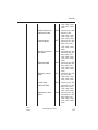
Table of Contents
INTRODUCTION
KHF 950/990 COMMUNICATIONS TRANSCEIVER . . . . . .I
SECTION I
CHARACTERISTICS OF HF SSB WITH ALE . . . . . . . .1-1
ACRONYMS AND DEFINITIONS . . . . . . . . . . . . . . .1-1
REFERENCES . . . . . . . . . . . . . . . . . . . . . . . . . . . . .1-1
HF SSB COMMUNICATIONS . . . . . . . . . . . . . . . . . .1-1
FREQUENCY . . . . . . . . . . . . . . . . . . . . . . . . . . . . . .1-2
SKYWAVE PROPAGATION . . . . . . . . . . . . . . . . . . . .1-3
WHY SINGLE SIDEBAND IS IMPORTANT . . . . . . .1-9
AMPLITUDE MODULATION (AM) . . . . . . . . . . . . . . .1-9
SINGLE SIDEBAND OPERATION . . . . . . . . . . . . .1-10
SINGLE SIDEBAND (SSB) . . . . . . . . . . . . . . . . . . .1-10
SUPPRESSED CARRIER VS.
REDUCED CARRIER . . . . . . . . . . . . . . . . . . . . . . .1-10
SIMPLEX & SEMI-DUPLEX OPERATION . . . . . . . .1-11
AUTOMATIC LINK ESTABLISHMENT (ALE) . . . . .1-11
FUNCTIONS OF HF RADIO AUTOMATION . . . . . .1-11
ALE ASSURES BEST COMM
LINK AUTOMATICALLY . . . . . . . . . . . . . . . . . . . . . .1-12
SECTION II
KHF 950/990 SYSTEM DESCRIPTION. . . . . . . . . . . . . .2-1
KCU 1051 CONTROL DISPLAY UNIT . . . . . . . . . . . .2-1
KFS 594 CONTROL DISPLAY UNIT . . . . . . . . . . . . .2-3
KCU 951 CONTROL DISPLAY UNIT . . . . . . . . . . . .2-5
KHF 950 REMOTE UNITS . . . . . . . . . . . . . . . . . . . . .2-6
KAC 952 POWER AMPLIFIER/ANT COUPLER .2-6
KTR 953 RECEIVER/EXITER . . . . . . . . . . . . . . .2-7
ADDITIONAL KHF 950 INSTALLATION OPTIONS .2-8
SINGLE KHF 950 SYSTEM CONFIGURATION .2-9
KHF 990 REMOTE UNITS . . . . . . . . . . . . . . . . . . . .2-10
KAC 992 PROBE/ANTENNA COUPLER . . . . .2-10
KTR 993 RECEIVER/EXITER . . . . . . . . . . . . . .2-11
SINGLE KHF 990 SYSTEM CONFIGURATION . . .2-12
Rev. 0
Dec/96
KHF 950/990 Pilots Guide
Toc-1
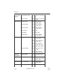
Table of Contents
SECTION III
OPERATING THE KHF 950/990 . . . . . . . . . . . . . . . . . . . . . .3-1
KHF 950/990 GENERAL OPERATING INFORMATION . . . .3-1
PREFLIGHT INSPECTION . . . . . . . . . . . . . . . . . . . . . . .3-1
ANTENNA TUNING . . . . . . . . . . . . . . . . . . . . . . . . . . . . .3-2
FAULT INDICATION . . . . . . . . . . . . . . . . . . . . . . . . . . . .3-2
TUNING FAULTS . . . . . . . . . . . . . . . . . . . . . . . . . . . . . . .3-3
KHF 950/990 CONTROLS-GENERAL . . . . . . . . . . . . . . .3-3
KCU 1051 CONTROL DISPLAY UNIT OPERATION . . . . . . .3-4
KCU 1051 GENERAL OPERATING INFORMATION . . .3-4
KCU 1051 CONTROL DESCRIPTION . . . . . . . . . . .3-4
PUSH ON/VOL . . . . . . . . . . . . . . . . . . . . . . . . . .3-4
SQUELCH . . . . . . . . . . . . . . . . . . . . . . . . . . . . .3-4
CURSOR . . . . . . . . . . . . . . . . . . . . . . . . . . . . . . .3-5
VAR/PUSH CHAR . . . . . . . . . . . . . . . . . . . . . . . .3-5
CLEAR . . . . . . . . . . . . . . . . . . . . . . . . . . . . . . . . .3-6
ENTER . . . . . . . . . . . . . . . . . . . . . . . . . . . . . . . .3-6
MESSAGE . . . . . . . . . . . . . . . . . . . . . . . . . . . . . .3-7
SCAN . . . . . . . . . . . . . . . . . . . . . . . . . . . . . . . . . .3-7
KCU 1051 DISPLAY AND CONTROL OPERATION 3-8
DISPLAY . . . . . . . . . . . . . . . . . . . . . . . . . . . . . . .3-8
PAGES . . . . . . . . . . . . . . . . . . . . . . . . . . . . . . . . .3-8
DATA STORE AND RECALL KEYS . . . . . . . . .3-10
CLR KEY . . . . . . . . . . . . . . . . . . . . . . . . . . .3-10
ENT KEY . . . . . . . . . . . . . . . . . . . . . . . . . . .3-10
MICROPHONE KEY OPERATION. . . . . . . . . .3-11
OPERATOR ALERTS . . . . . . . . . . . . . . . . . . . .3-11
COMMON DISPLAY FORMATS . . . . . . . . . . . .3-13
OPERATION / MODE FIELD . . . . . . . . . . . . . .3-14
STATE / SELECTION-CATEGORY FIELD . . . .3-14
RECEIVE./TRANSMIT STATE . . . . . . . . . . . . .3-14
MESSAGE/UNTUNED FLAG . . . . . . . . . . . . . .3-14
SECOND LINE OF DISPLAY . . . . . . . . . . . . . .3-14
LARGE DATA FIELDS . . . . . . . . . . . . . . . . . . .3-15
MANUAL MODE . . . . . . . . . . . . . . . . . . . . . . . . . . . . . . .3-15
FREQUENCY AGILE . . . . . . . . . . . . . . . . . . . . . . . .3-16
ITU CHANNEL OPERATION . . . . . . . . . . . . . . . . . .3-16
CHANGES TO ALE AND ITU CHANNELS . . . . . . .3-16
INITIAL MANUAL CHANNEL . . . . . . . . . . . . . . . . . .3-17
MANUAL CHANNEL ENTRY . . . . . . . . . . . . . . . . . .3-17
Toc-2
KHF 950/990 Pilots Guide
Rev. 0
Dec/96
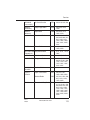
Table of Contents
ALE MODE . . . . . . . . . . . . . . . . . . . . . . . . . . . . . . . . . . .3-18
ALE IDLE STATES . . . . . . . . . . . . . . . . . . . . . . . . .3-18
ALE MODE DISPLAYS . . . . . . . . . . . . . . . . . . . . . .3-19
ALE IDLE SCANNING . . . . . . . . . . . . . . . . . . . . . . .3-20
ALE IDLE NOT SCANNING . . . . . . . . . . . . . . . . . . .3-20
ALE CALL IN PROGRESS . . . . . . . . . . . . . . . . . . .3-20
ALE LINKED TO ADDRESS . . . . . . . . . . . . . . . . . .3-21
ALE RECEIVING AMD MESSAGE . . . . . . . . . . . . .3-21
ALE SOUND RECEIVED FROM ADDRESS . . . . .3-22
ALE SOUNDING USING ADDRESS . . . . . . . . . . .3-22
SEND PAGE . . . . . . . . . . . . . . . . . . . . . . . . . . . . . . . . .3-23
SEND PAGE DISPLAYS . . . . . . . . . . . . . . . . . . . . .3-23
SEND MESSAGE PAGE (TRANSMIT AMD MESSAGE) 3-23
SEND SOUND AS PAGE (BROADCAST A SOUND) . .3-24
SEND LQA PAGE (PERFORM AN LQA) . . . . . . . . . . . .3-24
SYSTEM TEST . . . . . . . . . . . . . . . . . . . . . . . . . . . . . . . . . . .3-25
TEST REPORT PAGE . . . . . . . . . . . . . . . . . . . . . . . . . .3-25
SYSTEM REVNUM . . . . . . . . . . . . . . . . . . . . . . . . . . . . . . .3-26
SYSTEM LQA SCORE . . . . . . . . . . . . . . . . . . . . . . . . . . . . .3-26
LQA SCORE PAGE . . . . . . . . . . . . . . . . . . . . . . . . . . . .3-26
SYSTEM PROGRAM . . . . . . . . . . . . . . . . . . . . . . . . . . . . . .3-27
PROGRAM MESSAGES . . . . . . . . . . . . . . . . . . . . . . . .3-29
EDIT TX (EDIT AMD TRANSMIT MESSAGES) . . .3-29
REV RX (REVIEW RECEIVED AMD MESSAGES) 3-30
DEL RX (DELETE AMD RECEIVED MESSAGE) .3-30
DEL RX (ALL SELECTED) . . . . . . . . . . . . . . . . . . .3-31
COPY RX . . . . . . . . . . . . . . . . . . . . . . . . . . . . . . . . .3-31
PROGRAM OPERATION . . . . . . . . . . . . . . . . . . . . . . . .3-31
INTERVAL . . . . . . . . . . . . . . . . . . . . . . . . . . . . . . . .3-32
ACTIVITY LIMIT TIME-OUT PERIOD . . . . . . . .3-33
SCAN RATE . . . . . . . . . . . . . . . . . . . . . . . . . . .3-33
AUTOMATIC SOUNDING INTERVAL . . . . . . .3-33
CALLTIME . . . . . . . . . . . . . . . . . . . . . . . . . . . . .3-33
Rev. 0
Dec/96
KHF 950/990 Pilots Guide
Toc-3
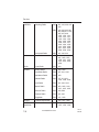
Table of Contents
ENABLES . . . . . . . . . . . . . . . . . . . . . . . . . . . . . . . .3-34
ENABLE AUTOMATIC SOUNDING . . . . . . . . .3-35
ENABLE LQA IN CALL . . . . . . . . . . . . . . . . . . .3-35
ENABLE RECEPTION OF AMD MESSAGES . .3-35
ENABLE RECEPTION OF ANYCALLS . . . . . . .3-35
ENABLE RECEPTION OF ALLCALLS . . . . . . . .3-35
ENABLE RECEPTION OF WILDCARD CALLS 3-35
ENABLE NUMERIC DIGIT ROLL OVER . . . . . .3-36
BRIGHTNESS SETTING . . . . . . . . . . . . . . . . . . . . .3-36
PROGRAM CHANNEL . . . . . . . . . . . . . . . . . . . . . . . . . .3-37
ALE CHANNEL DATA . . . . . . . . . . . . . . . . . . . . . . .3-37
CHANNEL GROUPS (CHGRP) . . . . . . . . . . . . . . . .3-38
SCAN-LIST (SCAN-LIST) . . . . . . . . . . . . . . . . . . . .3-39
TUNE ALL UNTUNED CHANNELS (TUNE-ALL) . .3-39
NEED TUNE COMPLETED . . . . . . . . . . . . . . .3-39
CLEAR TUNES FROM ALL TUNED CHANNELS .3-40
MARKING UNTUNED . . . . . . . . . . . . . . . . . . . .3-40
PROGRAM ADDRESS . . . . . . . . . . . . . . . . . . . . . . . . .3-41
ALE ADDRESS ENTRY PAGE . . . . . . . . . . . . . . . .3-41
SINGLE ADDRESS ENTRY . . . . . . . . . . . . . . . . . . .3-44
SELF ADDRESS . . . . . . . . . . . . . . . . . . . . . . . .3-44
RESPONSE TIME . . . . . . . . . . . . . . . . . . . . . . .3-45
SPECIAL ADDRESS TYPES . . . . . . . . . . . . . . . . . .3-45
MESSAGE PAGE . . . . . . . . . . . . . . . . . . . . . . . . . . . . . . . . .3-46
KCU 1051 OPERATIONS SUMMARY . . . . . . . . . . . . . . . . .3-48
KCU 951 CONTROL DISPLAY UNIT OPERATION . . . . . . .3-50
KCU 951 CONTROLS . . . . . . . . . . . . . . . . . . . . . . . . . .3-50
OFF/VOLUME . . . . . . . . . . . . . . . . . . . . . . . . . . . . .3-50
SQUELCH/OPTIONAL SELCAL . . . . . . . . . . . . . . .3-51
CLARIFIER . . . . . . . . . . . . . . . . . . . . . . . . . . . . . . .3-52
MODE BUTTON . . . . . . . . . . . . . . . . . . . . . . . . . . .3-52
FREQ/CHAN BUTTON . . . . . . . . . . . . . . . . . . . . . .3-53
DIRECT TUNING A FREQUENCY . . . . . . . . . . . . .3-54
CHANNEL OPERATION AND PROGRAMMING 1 .3-55
CHANNEL OPERATION AND PROGRAMMING 2 .3-56
RECEIVE-ONLY CHANNEL PROGRAMMING . . . .3-57
SIMPLEX CHANNEL PROGRAMMING . . . . . . . . .3-59
SEMI-DUPLEX CHANNEL PROGRAMMING . . . . .3-60
Toc-4
KHF 950/990 Pilots Guide
Rev. 0
Dec/96
Table of Contents
KFS 594 CONTROL DISPLAY UNIT OPERATION . . . . . . .3-62
KFS 594 CONTROLS . . . . . . . . . . . . . . . . . . . . . . . . . .3-62
OFF/VOLUME . . . . . . . . . . . . . . . . . . . . . . . . . . . . .3-62
SQUELCH/OPTIONAL SELCAL . . . . . . . . . . . . . . .3-63
MODE SELECTION . . . . . . . . . . . . . . . . . . . . . . . . . . . .3-63
USB MODE A3J MODE . . . . . . . . . . . . . . . . . . . . . .3-63
DIRECT TUNING A FREQUENCY . . . . . . . . . . . . .3-64
CHANNEL OPERATION AND PROGRAMMING . .3-66
SIMPLEX CHANNEL PROGRAMMING . . . . . . . . .3-67
SEMI-DUPLEX CHANNEL PROGRAMMING . . . . .3-68
CLARIFIER . . . . . . . . . . . . . . . . . . . . . . . . . . . . . . .3-70
MARITIME RADIOTELEPHONE NETWORK . . . . .3-71
KFS 594 OPERATIONAL NOTES: . . . . . . . . . . . . . . . .3-73
SECTION IV
HF COMMUNICATIONS SERVICES DIRECTORY . . . . .4-1
SECTION V
ICAO ENROUTE NETWORKS . . . . . . . . . . . . . . . . . . . .5-1
HF RADIOTELEPHONE NETWORKS MAP . . . . . . . . . . .5-3
SECTION VI
ARINC OPERATIONAL CONTROL SERVICES . . . . . . . .6-1
DESCRIPTION OF SERVICES . . . . . . . . . . . . . . . . .6-1
ARINC OPERATING PROCEDURES . . . . . . . . . . . .6-2
AUTHORIZED CONNECTIONS . . . . . . . . . . . . .6-2
GROUND-TO-AIRCRAFT CALLS . . . . . . . . . . . .6-3
ARINC LONG DISTANCE CONTROL FACILITIES . .6-5
SECTION VII
ITU MARITIME RADIOTELEPHONE STATIONS . . . . . .7-1
DESCRIPTION OF SERVICES . . . . . . . . . . . . . . . . . . . .7-1
AT&T HIGH SEAS RADIOTELEPHONE SERVICE .7-2
AT & T COAST STATION COVERAGE MAP . . . . . .7-3
COAST STATION COVERAGE & INFORMATION . .7-3
AIRCRAFT REGISTRATION . . . . . . . . . . . . . . . . . . .7-4
USING THE HIGH SEAS RADIO NETWORK . . . . . .7-4
PLACING AIRCRAFT-TO-GROUND CALLS . . .7-4
RECEIVING HIGH SEAS CALLS . . . . . . . . . . . .7-5
PLACING GROUND-TO-AIRCRAFT CALLS . . .7-5
TELEPHONE SERVICES OFFERING . . . . . . . .7-5
HIGH SEA RATE STRUCTURE . . . . . . . . . . . . .7-6
TRAFFIC LIST BROADCAST . . . . . . . . . . . . . . .7-6
Rev. 0
Dec/96
KHF 950/990 Pilots Guide
Toc-5
Table of Contents
AT&T HIGH SEAS COAST STATIONS . . . . . . . . . . .7-6
A FEW VITAL FACTS . . . . . . . . . . . . . . . . . . . . .7-6
COAST STATION KMI-CALIFORNIA . . . . . . . . .7-7
COAST STATION WOO - NEW JERSEY . . . . . .7-8
COAST STATION WOM - FLORIDA . . . . . . . . . .7-9
MOBILE MARINE RADIO, INC. . . . . . . . . . . . . . . . .7-11
WORLD WIDE LISTING OF PUBLIC
CORRESPONDENCE STATIONS . . . . . . . . . . . . .7-12
MARITIME RADIO CHANNEL DESIGNATIONS . . .7-14
SECTION VIII
TIME & FREQUENCY STANDARD . . . . . . . . . . . . . . . .8-1
DESCRIPTION OF SERVICES . . . . . . . . . . . . . . . . . . . .8-1
WWV AND WWVH . . . . . . . . . . . . . . . . . . . . . . . . . .8-1
TIME ANNOUNCEMENTS . . . . . . . . . . . . . . . . . . . .8-2
GEOPHYSICAL ALERTS ON WWV . . . . . . . . . . . . .8-3
OMEGA NAV SYSTEM STATUS REPORTS . . . . . . .8-5
GLOBAL POSITIONING SYSTEM (GPS)
STATUS ANNOUNCEMENTS . . . . . . . . . . . . . . . . . .8-5
MARINE STORM WARNINGS . . . . . . . . . . . . . . . . .8-5
TIME AND FREQUENCY SERVICES WORLDWIDE 8-7
SECTION IX
VOLMETS . . . . . . . . . . . . . . . . . . . . . . . . . . . . . . . . . . . .9-1
SECTION X
EMERGENCY FREQUENCIES . . . . . . . . . . . . . . . . . . .10-1
INTERNATIONAL DISTRESS FREQUENCY . . . . . . . .10-1
SECTION XI
SHORTWAVE BROADCASTS . . . . . . . . . . . . . . . . . . .11-1
SECTION XII
MANUAL AND ALE PROGRAMMING . . . . . . . . . . . . . .12-1
MANUAL DATABASE PROGRAMMING . . . . . . . . .12-1
MANUAL CHANNEL PROGRAMMING . . . . . .12-1
PROGRAMMING FREQUENCY . . . . . . . . . . . .12-2
PROGRAMMING MODULATION TYPE . . . . . .12-2
ALE DATABASE PROGRAMMING . . . . . . . . . . . . .12-2
SYSTEM PROGRAM PAGE . . . . . . . . . . . . . . .12-3
AMD TRANSMIT MESSAGES . . . . . . . . . . . . .12-5
OPERATION PARAMETERS . . . . . . . . . . . . . .12-5
PROGRAMMING OPERATION
PARAMETERS . . . . . . . . . . . . . . . . . . . . . .12-6
Toc-6
KHF 950/990 Pilots Guide
Rev. 0
Dec/96
Table of Contents
ALE CHANNEL DATABASE . . . . . . . . . . . . . . .12-7
PROGRAMMING ALE CHANNELS . . . . . .12-7
PROGRAMMING CHANNEL GROUPS . .12-7
PROGRAMMING THE SCAN LIST . . . . . . .12-8
ALE ADDRESSES . . . . . . . . . . . . . . . . . . . . . . .12-8
ALE ADDRESS PROGRAM PAGE . . . . . .12-9
PROGRAMMING A SELF ADDRESS . . . .12-9
PROGRAMMING A SINGLE ADDRESS .12-10
PROGRAMMING A STAR NETWORK
ADDRESS . . . . . . . . . . . . . . . . . . . . . . . . .12-11
PROGRAMMING A GROUP ADDRESS .12-12
PROGRAMMING A SPECIAL ADDRESS
TYPE . . . . . . . . . . . . . . . . . . . . . . . . . . . . .12-13
SECTION XIII
APPENDICES . . . . . . . . . . . . . . . . . . . . . . . . . . . . . . . . . . .13-1
APPENDIX A: GEOPHYSICAL ALERT BROADCASTS 13-1
VOICE MESSAGE GEOPHYSICAL ALERTS ON WWV 13-1
GLOSSARY OF TERMS FOR THE SESC WWV
VOICE MESSAGE . . . . . . . . . . . . . . . . . . . . . . . . . . . . .13-2
APPENDIX B: FREQUENCY STANDARD SERVICES 13-4
APPENDIX C: ADDITIONAL MATERIAL ON HF RADIO 13-5
APPENDIX D: FCC APPLICATION . . . . . . . . . . . . . . . .13-6
Rev. 0
Dec/96
KHF 950/990 Pilots Guide
Toc-7
Table of Contents
This Page Intentionally Left Blank
Toc-8
KHF 950/990 Pilots Guide
Rev. 0
Dec/96
Introduction
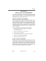
INTRODUCTION
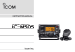
KHF 950/990 COMMUNICATIONS TRANSCEIVER
High frequency (HF) communications made easy, that’s what the
King KHF 950/990 HF SSB Transceiver is all about.
The KHF 950/990 is a compact, lightweight system to provide an
extensive range of operator benefits. It is designed with international
flight operations in mind to provide superior long range communications.
A basic KHF 950/990 system consists of either three or four units
including your choice of either a miniature Gold Crown III style (KFS
594) or two different Dzus rail-mounted control display units (KCU
951 & KCU 1051). Additional hardware is available to allow the KHF
950 system to tune most shunt and notch antennas used on some
corporate jet aircraft. It can also be installed in a dual configuration
sharing the same HF antenna, and yet provide a dual receive capability which many corporate users find highly desirable. The KCU
1051 will provide Automatic Link Establishment (ALE). This allows
automatic selection of the optimum frequency and linking to another
ALE system.
Microprocessor control of vital frequency selection functions provides
an unprecedented number of programmable channels, greater ease
of changing these channels on the ground or in the air, and direct
access to a full 280,000 operating frequencies from 2.0 to 29.9999
MHz. The control heads provide extreme ease in fully utilizing the
semi-duplex channels of the maritime radiotelephone (public correspondence) network.
There are three types of control heads available. The KCU 1051
control display unit provides Automatic Link Establishment (ALE)
capability. The KCU 1051 is a Dzus rail-mounted unit with 200 programmable channels, 100 for manual channels and 100 for ALE
channels, also all 245 ITU channels used by the maritime radiotelephone network are preprogrammed into non-volatile memory. No
additional programming of ITU channels is ever required. With the
KCU 951 Dzus rail-mounted control display unit, 99 pilot programmable channels are available. With the KFS 594 miniature control display unit and its associated remote adapter unit, 19 pilot programmable channels are available and, in addition, all 245 ITU channels used
by the maritime radiotelephone network are preprogrammed into
nonvolatile memory. When the KFS 594 Control Display Unit is used,
no additional programming of ITU maritime radiotelephone network
channels is ever required.
Rev. 0
Dec/96
KHF 950/990 Pilots Guide
i
Introduction
High frequency radio opens a world of communication possibilities to
the pilot and his passengers, including long range contact with air
traffic control agencies over thousands of miles away, time and frequency standard broadcasts, Omega navigation station status
reports, weather and marine storm warnings, radiotelephone service
for personal messages and ARINC operational control services for
messages relating to flying operations.
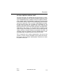
The first section of this pilot’s guide deals with high frequency communications in general. A basic understanding of single sideband and
some of the conditions which influence HF communications is important to using the KHF 950/990 effectively and obtaining the maximum
benefit from its extensive capabilities.
The second section details the actual operation of the KHF 950/990
system and the final section of this pilot’s guide covers the wide variety of HF communications services which are available to the pilot
using the Bendix/King KHF 950/990.
ii
KHF 950/990 Pilots Guide
Rev. 0
Dec/96
Description
SECTION I
CHARACTERISTICS OF HF SSB
COMMUNICATIONS WITH AUTOMATIC
LINK ESTABLISHMENT.
ACRONYMS AND DEFINITIONS
ALE
Automatic Link Establishment
AMD
Automatic Message Display
CDU
Control Display Unit
HF
High Frequency
KPN
King Part Number
LQA
Link Quality Analysis
PC
IBM compatible Personal Computer
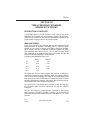
REFERENCES
The following documents are referenced by this document.
MIL-STD-188-141A Appendix A Notice 2
Automatic Link Establishment System, 10 September 1993
Federal Standard 1045A
Telecommunications: HF Radio Automatic Link Establishment,
24 January 1990
HF SSB COMMUNICATIONS
High frequency single side band communications achieve reliable
long range transmission and reception over distances of thousands
of miles. The primary reason is due to skywave propagation which
allows HF radio waves which are beamed toward outer space to be
reflected back toward the earth’s surface by the ionosphere. Another
reason is because of a transmission process known as single sideband which puts all the transmitter’s power into sending just a radio
Rev. 0
Dec/96
KHF 950/990 Pilots Guide
1-1
Description
wave containing the intelligence to be communicated. Both of these
make HF radio highly useful to aircraft flying over water or desolate
land areas when they are out of reach of VHF communications which
are limited to line of sight transmissions. A familiarization with frequency, skywave propagation, amplitude modulation, single sideband
operation, suppressed carrier versus reduced carrier, simplex and
semi-duplex operation, and automatic link establishment will make
this pilot’s guide easier to use and understand.
The following explanations will help provide a base to build on as you
acquire experience in operating your KHF 950/990. If you have had
experience with HF radio previously, the following material will serve
as a review.
FREQUENCY
The frequency of a radio wave is the number of cycles of that radio
wave which pass a given point within one second. The longer the
wavelength, the lower the frequency. The frequency is often
expressed as cycles per second, with one complete wave representing a cycle. The term hertz (Hz) is more commonly used today to
represent one cycle per second. Expression of the measurement Hz
has a shorthand of its own. When thousands of Hz are expressed,
they are designated kilohertz (kHz), and millions of Hz as megahertz (MHz). Thus the notation 29.9999 MHz represents a signal
which is passing a given point at 29,999, 900 cycles per second.
Expressed in kHz, the same Figure would read 29,999.9 kHz representing 29,999.9 thousand cycles per second. In using HF, you will
encounter both MHz and kHz notations for frequencies. KFS 594 and
KCU 951 control display units always express frequencies in terms of
kHz. The KCU1051 control display unit always expresses frequencies in terms of MHz.
The high frequency (HF) band , with which we are primarily concerned in this pilot’s guide, covers from 2.0 MHz to 30 MHz (2,000
kHz to 30,000 kHz). The HF band lies between the medium frequency (MF) band and the very high frequency (VHF) band. Pilots are
familiar with the characteristics of MF frequencies through the use of
ADF equipment and know that these signals hug the ground and are
sensitive to variations in terrain and to atmospheric disturbances. On
the other hand, pilots know that VHF frequencies such as are used in
VOR navigation and normal communications with Air Traffic Control
facilities generally travel line-of-sight range and are not greatly affected by atmospheric disturbances. As will be discussed next, HF has
its own characteristics which allow long range communications to
take place.
1-2
KHF 950/990 Pilots Guide
Rev. 0
Dec/96
Description
SKYWAVE PROPAGATION - WHICH FREQUENCY TO
USE?
As mentioned earlier, HF’s primary method of travel or propagation is
via skywaves which are radio waves that start out radiating into
space and are reflected off the ionosphere back to the earth’s surface. This reflecting of signals makes communications over very long
distances-under ideal conditions more than 4,000 miles and typically
in excess of 2,000 miles-possible. Because of variations in the ionosphere, HF communications require more analysis of conditions and
operational decisions (such as frequency selection) than VHF communications.
The ionosphere is a multi-layered band of electrically charged particles surrounding the earth. It varies in height above the surface of the
earth from approximately 30 to over 400 miles. The height and intensity varies from one location to the next and according to the season
of the year and the time of day.
Because HF radio waves depend upon the ionosphere for reflection,
their propagation is affected by changes in the ionosphere. It is
changes in the density of the electrically charged particles in the
ionosphere which cause propagation to improve or deteriorate. Since
the ionosphere is formed primarily by the action of the sun’s ultraviolet radiation, its thickness changes in relation to the amount of sunlight passing through it. Sunlight-induced ionization increases the particle density during the day and the absence of it reduces the particle
density at night. At midday, when the sun’s radiation is at its highest,
the ionosphere’s thickness may expand into four layers of ionized
gas. During the nighttime hours, the ionosphere diminishes, normally
merging into just one layer.
Solar disturbances including solar flares and magnetic storms can
cause propagation of HF radio waves to deteriorate rapidly. HF signals can also suffer interference from such atmospheric disturbances
as precipitation and thunderstorms.
The net result of all these factors is that because the ionospheric and
atmospheric conditions are constantly changing, HF communications
can vary in quality and strength. The signal received on the KHF
950/990 may be accompanied by a considerable amount of static
from atmospheric disturbances, or it may fade in and out at times
because each radio wave which hits the changing ionosphere may
be reflected differently. Your reception and transmission success may
vary from loud and clear to nonexistent depending on your selection
of frequency and the conditions in the atmosphere and the ionosRev. 0
Dec/96
KHF 950/990 Pilots Guide
1-3
Description
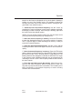
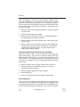
phere. One of the best things the pilot can do to assure the best possible HF communications, based on existing HF propagation conditions, is to select the proper frequency. A good rule of thumb for the
time of day is that the higher frequencies are best during daylight (10
to 29.9999 MHz) and lower frequencies work best at night (2 to 10
Mhz).
This rule of thumb can be explained by a mirror analogy. It is the
electrically charged particles in the ionosphere which reflect or bend
radio waves back toward earth like a mirror reflects light. Sunlight
induces ionization and increases the density of these particles in the
ionosphere during the day. The mirror becomes thicker and it reflects
higher frequencies better. When the sun goes down the density of
charged particles decreases and the ionosphere becomes a mirror
that can only reflect lower frequencies in the HF band.
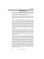
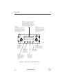
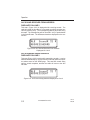
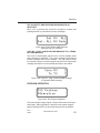
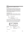
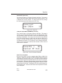
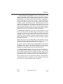
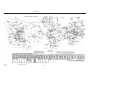
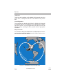
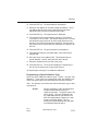
For any one particular frequency, as the angle at which an HF radio
wave hits a layer of the ionosphere is increased, a critical angle will
be reached from which the wave will just barely manage to be reflected back to earth (Figure 1-1). Waves entering at sharper angles than
this will pass through this layer of the ionosphere and be lost in space
(or may reflect off another layer of the ionosphere).
Changing the frequency under the same conditions will change the
critical angle at which the HF radio waves will be reflected back to
earth. The highest frequency which is reflected back to the earth is
called the maximum useable frequency (MUF). The best HF communications are usually obtained using a frequency as close to the MUF
as possible since radio waves higher than this frequency are not
reflected and radio waves lower than this frequency will be partially
absorbed by the ionosphere.
You should also be aware of the possibility that you or the ground
station you are calling may be in a quiet zone. The linear distance
from the point of transmission to the point where the skywave returns
to earth is called the skip distance. There may be a quiet zone
between the end of the ground wave and the return of the skywave.
No communication can take place in this area. At any time, day or
night, there is a “window” of useable frequencies created by the
reflecting properties of the ionosphere. At night this “window” will normally be in the lower range of HF frequencies, and during the day it
will be in the higher range of frequencies.
Normally you will not know what the MUF is at any particular time and
location unless you have a table of propagation forecasts. Just
remember that the higher frequencies in the “window” of useable fre-
1-4
KHF 950/990 Pilots Guide
Rev. 0
Dec/96
Description
quencies are likely to be the most effective. The closer a frequency is
to the MUF, the better it is likely to be.
FR
AC
TIO
N
The effect of solar disturbances including solar flares and magnetic
storms is to change the particle density in the ionosphere. Therefore,
the “window” of useable frequencies may begin to close, with radio
waves of frequencies in the lower range dropping out first as they are
absorbed by the ionosphere.
RE
IONOSPHERE
E
GL
AL
C
ITI
AIRCRAFT
T
AF
CR
AIR
QUIET ZONE
NE
E
SK
ZO DISTANC
YW
E
P
V KI
AV
DESIRED PATH DISTA
E
WA M S
N
ZO
CE
D U
N
M
N
U INI
M
E
G
RO
CR
AN
EARTH
Figure 1-1 Effects Of Different Skywave Paths
Next, the radio waves of upper frequencies in the useable “window”
may start to penetrate the ionosphere and go into outer space. It is
even possible for the entire “window” to close, particularly if you are
flying in a polar region in latitudes above 60 degrees north or 60
degrees south. Solar disturbances have the most negative effects on
HF communications in these regions.
If you are flying in polar regions and are having difficulty raising any
ground station located in the same region, remember this: even
though the “window” of useable frequencies may have closed in the
polar regions, another “window” may be open in regions closer to the
equator which are less affected by solar disturbances. Try calling a
station closer to the equator in latitudes lower than 60 degrees north
or 60 degrees south, and use a higher frequency. If you can raise a
station in these areas, that station may be able to relay your message.
Rev. 0
Dec/96
KHF 950/990 Pilots Guide
1-5
Description
There are even times when solar disturbances improve the usability
of higher frequencies in the HF band, particularly in equatorial
regions. Another phenomenon which occurs during solar disturbances may allow you to communicate with a station even though the
“window” is closed. This is known as scatter propagation, in which a
radio wave is broken up in the ionosphere and scatters in various
directions. Refer to the discussion of geophysical alerts in Appendix
A for information on broadcasts which announce solar disturbance
phenomena, and how to interpret these broadcasts.
Because frequency propagation cannot be predicted with total accuracy, ground stations responsible for aircraft HF communications will
typically operate on several different frequencies within the HF band.
The pilot is then able to choose the optimum communication frequency for the existing ionospheric conditions.
One feature that will be particularly useful when a trial and error
method is used to find an HF frequency which is working well. This is
the system’s capability to be programmed by the pilot with 99 channels (using the KCU 951 Control Display Unit), 100 channels (using
the KCU1051 control display unit) or 19 (using the KFS 594 miniature
control display unit). Rather than having to select the four to six digits
each time you want to try another frequency, you can preprogram the
frequencies you need to contact a particular ground station. Then if
you call and fail to get through, you just change to another channel.
(Automatic channel selection for optimum communications reliability
is simplified with the addition of Automatic Link Establishment (ALE),
available on the KCU 1051 Control Display Unit.
NOTE: It is advisable to program at least three frequencies for each
station you plan to contact, in case one frequency suddenly becomes
unusable. During times of solar disturbances, a useable frequency
can fade out in less than a minute. And the “window” of useable frequencies can shift rapidly during solar disturbances or during sunset
and sunrise when the level of ionization in the ionosphere is changing rapidly.
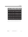
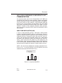
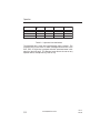
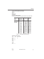
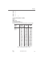
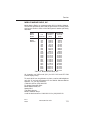
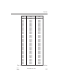
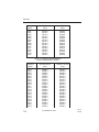
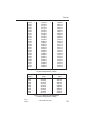
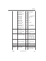
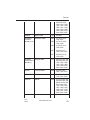
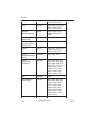
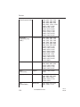
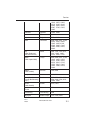
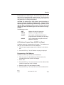
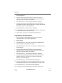
Tables 1-1 and 1-2 show typical propagation distances after one
reflection from the ionosphere for various frequencies during different
hours of the day and for different seasons of the year. It may prove
helpful in selecting the optimum HF frequency for the communications distance your operation requires.
1-6
KHF 950/990 Pilots Guide
Rev. 0
Dec/96
Description
Frequency (kHz)
4000
Propagation (Miles)
Min
Max
Hours After Sunset
1
50
250
2
100
600
3
100
600
4
100
800
5
100
1000
6
100
1500
7
100
1500
8
250
2000
9
250
2500
10
250
2500
11
100
1000
Hours After Sunrise
1
100
500
2
0
100
3
0
100
4
0
100
5
0
100
6
0
100
7
0
100
8
0
100
9
0
100
10
0
100
11
0
100
12
0
200
13
50
250
8000
12000
16000
Min
Max
Min
Max
Min
Max
200
250
250
250
250
400
500
750
750
750
500
1000
1500
2000
2500
2500
3000
3500
4000
4000
4000
2500
500
500
500
3500
3500
3500
750
750
6000
6000
400
400
250
250
250
250
250
250
250
250
150
150
150
2000
2000
1500
1500
1500
1500
1500
1500
1500
1500
500
500
750
500
500
500
500
500
500
500
500
500
500
1000
1500
2500
3500
3500
3500
3500
3500
3500
3500
750
750
750
750
750
750
750
750
4000
4000
4000
4000
4000
6000
6000
6000
Table 1-1 Typical Frequency Propagation Spring And Summer
Rev. 0
Dec/96
KHF 950/990 Pilots Guide
1-7
Description
Frequency (kHz)
4000
Propagation (Miles)
Min
Max
Hours After Sunset
1
100
600
2
100
800
3
100
1000
4
100
1000
5
100
1000
6
100
1500
7
250
2000
8
250
2500
9
500
3000
10
500
4000
11
500
3000
12
250
2500
13
250
1500
Hours After Sunrise
1
100
1000
2
100
500
3
0
100
4
0
100
5
0
100
6
0
100
7
0
100
8
0
100
9
0
100
10
0
100
11
0
250
8000
12000
16000
Min
Max
Min
Max
Min
Max
400
400
400
400
400
400
400
500
500
500
750
750
500
2000
2000
2000
2500
3000
3500
4000
4000
4000
4000
5000
5000
2500
500
500
500
500
500
3500
4000
4000
4000
4000
750
750
6000
6000
400
400
400
400
250
250
250
250
250
250
250
2000
2000
2000
2000
1500
1500
1500
1500
1500
1000
1500
500
500
500
500
500
500
500
500
3500
3500
3500
3500
4000
4000
4000
3500
3500
750
750
750
750
750
750
750
750
750
4000
4000
4000
4000
5000
5000
6000
6000
6000
Table 1-2 Typical Frequency Propagation For Fall And Winter
1-8
KHF 950/990 Pilots Guide
Rev. 0
Dec/96
Description
WHY SINGLE SIDEBAND IS IMPORTANT IN HF
COMMUNICATIONS
As mentioned earlier, there are two characteristics of HF SSB communications which allow long range capability. Skywave propagation
has been discussed in detail. The other characteristic is a transmission process known as single sideband. Single sideband (SSB) high
frequency (HF) communications was developed in the early 1950’s
as a means of increasing the effective range of HF signals. The KHF
950/990 is capable of both amplitude modulation (AM) operation,
such as is used in conventional VHF aircraft communications, and of
SSB operation.
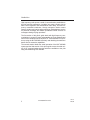
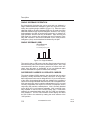
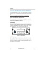
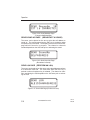
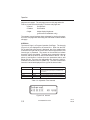
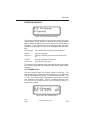
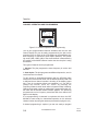
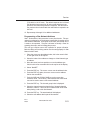
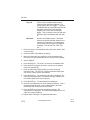
AMPLITUDE MODULATION (AM)
In order to understand SSB operation, a discussion of AM operation
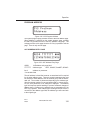
is helpful. Amplitude Modulation (AM) is a transmission process in
which the selected frequency (called the carrier frequency) and two
sidebands (which are frequencies above and below the carrier frequency) are generated and transmitted. (Figure 1-2.) It takes about
two-thirds of the transmitter’s power just to transmit the carrier frequency, yet the carrier does not contain any of the intelligence to be
communicated. Each of these sidebands contains all the intelligence
to be communicated. Standard broadcast stations (550-1600 kHz)
and short-wave broadcasts use AM since it allows simpler receivers.
NOTE: The use of lower sideband isn’t normally authorized for airborne HF use. It is normally disabled in the KHF 950/990, but can be
enabled for those who are authorized to use it.
AMPLITUDE MODULATION (AM)
fc = carrier frequency
fm = modulating frequency (voice)
fc-fm
LSB
fc
fc+fm
USB
Figure 1-2 Amplitude Modulation
Rev. 0
Dec/96
KHF 950/990 Pilots Guide
1-9
Description
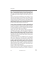
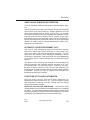
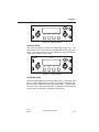
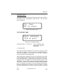
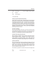
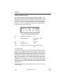
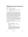
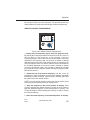
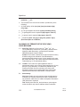
SINGLE SIDEBAND OPERATION
By electronically eliminating the carrier wave and one sideband, a
single sideband transmitter manages to pack all of its power in transmitting the remaining single sideband. (Figure 1-3). Either the upper
sideband (USB) or the lower sideband (LSB) can be used since each
sideband contains all the required intelligence. However, from a practical standpoint the USB is used almost exclusively in airborne HF
SSB operations and the LSB may be disabled. Upon receiving this
SSB signal, the receiver then generates the carrier frequency internally and combines it with the one sideband in such a way that the
intelligence (voice) can be heard and understood by the pilot.
SINGLE SIDEBAND (SSB)
SINGLE SIDEBAND (SSB)
fc = carrier frequency
fm = modulating frequency (voice)
fc-fm
LSB
fc
fc+fm
USB
Figure 1-3 Single Sideband
The result is that an SSB system has the effective transmit power of
AM units having many more times the transmitter power. Also, SSB
communications allow the frequency band to be utilized more efficiently since the space or “bandwidth” of only one sideband rather
than two sidebands is required to transmit the message.
SUPPRESSED CARRIER VS. REDUCED CARRIER
The single sideband (SSB) operation just described with the carrier
frequency virtually eliminated is actually referred to as single sideband suppressed carrier and is designated A3J. If just a small portion
of the carrier is transmitted along with the sideband, the operation is
referred to as single sideband reduced carrier and is designated A3A.
A3A was previously used in maritime radiotelephone but is not used
currently. Regulations still require its inclusion in equipment used in
conjunction with maritime radiotelephone. A3A is normally disabled
on the KCU 1051, but is harness selectable. A3A is normally internally disabled on the KCU 951 Control Display Unit. If it has been
enabled it is annunciated when both “AM” and “USB” are simultaneously displayed. The KFS 594 miniature control display unit allows
the A3A mode to be selected by rotating the mode selector to the
“A3A” position.
1-10
KHF 950/990 Pilots Guide
Rev. 0
Dec/96
Description
SIMPLEX AND SEMI-DUPLEX OPERATION
The KHF 950/990 is capable of both simplex and semi-duplex operation.
Simplex operation means that communication signals are transmitted
and received on the same frequency. Simplex operations are used
when communicating with Air Traffic Control (ATC), for example.
Semi-duplex operation means that messages are transmitted on one
frequency and received on another. The HF operator selects separate transmit and receive frequencies, then keys the microphone to
transmit and releases the push-to-talk switch to receive. Semi-duplex
operation is usually used for maritime radiotelephone (public correspondence) communications.
AUTOMATIC LINK ESTABLISHMENT (ALE)
ALE is an HF radio management system that selects the optimum
frequency of transmission, places automatic or manual calls to link
one or more users, and communicates digital messages. The ALE
specification and waveform were adopted as standards by the US
government in September, 1988 as MIL-STD 188-141A (Appendix A)
for the military and as Federal Standard 1045 for civilian government
agencies.
The advent of ALE technology has changed HF communications by
allowing systematic and automatic real-time evaluation of HF communications paths, permitting automatic frequency selection.
Because of this, the operation of an HF radio with Automatic Link
Establishment is greatly simplified and the communications reliability
is increased. A KCU 1051 CDU is required when Automatic Link
Establishment features are desired.
FUNCTIONS OF HF RADIO AUTOMATION
There are many functions, that the HF Radio Automatic Link
Establishment System performs for you. They are Selective Calling
and Handshake, Scanning, Sounding, Polling, and Link Quality
Analysis and Channel Selection
SELECTIVE CALLING AND HANDSHAKE - The selective calling
and handshake function enables the establishment of a link between
two radios. It includes digital address selective calling, followed by an
exchange consisting of a response and acknowledgment, to produce
a handshake (the establishment of a communications link).
Rev. 0
Dec/96
KHF 950/990 Pilots Guide
1-11
Description
SCANNING - All available stations continuously and rapidly scan
their receivers through their channels, seeking ALE calls. At any
time, a calling station may slowly scan its transmitter through their
channels, calling on each one, until answered on a channel that supports contact. This function enables the selection of a channel that
successfully supports contact, despite variations in propagation,
occupancy, and other traditional HF challenges.
SOUNDING - Sounding is a special beacon-like technique that
assists all listening stations in measuring the propagation from the
sounding station. The sounding station transmits its address on all
channels, and the other stations measure the quality of the received
signal. Sounding stations provide this service to other stations and
do not use the information themselves.
POLLING - Polling enables two radios to measure the propagation
characteristics for each channel’s receive and transmit path. Then the
information is stored in non-volatile memory.
LINK QUALITY ANALYSIS AND CHANNEL SELECTION - This
function enables the radio to measure the quality of the received signals (and thus the available links) and to select the best channel for
calling and communicating. This function allows a calling station to
initiate calling on the best known working channel and thereby speed
linking. It also minimizes unnecessary calling on marginal channels,
when a transmitting station knows how well its signal is being
received by the intended stations.
HOW ALE ASSURES THAT THE BEST COMMUNICATIONS LINK IS CHOSEN AUTOMATICALLY EVERY TIME
With Automatic Link Establishment on the job, the radio constantly
scans the available channels for an ALE transmission. ALE transmissions are digitized HF signals. When an ALE transmission is
detected, the signal-to-noise ratio of that signal is retained in memory.
The next time a call is made, the radio uses that signal-to-noise ratio
to determine the best channel to use. This way the best channel is
always the one used, allowing you to have the best possible communications link all the time, in spite of the constantly changing thickness, density, and reflectivity of the ionosphere (a condition that is not
controllable). Every frequency reacts a little differently to random
changes in the ionosphere. The link quality for one frequency may
increase while it may decrease for another for the same random
changes.
1-12
KHF 950/990 Pilots Guide
Rev. 0
Dec/96
Description
ALE relieves you of the burden of trying to manually detect and
compensate for random changes in the ionosphere and of
searching for a good channel to use. It lets you concentrate on
the message to be sent.
During the time when no call is present, the radio is squelched to
reduce noise in the cockpit. After a call is received, a sound like a
phone ringing is heard, the radio un-squelches, and you can commence a normal HF communication. ALE relieves you of the burden of monitoring the radio for the presence of an HF call.
Rev. 0
Dec/96
KHF 950/990 Pilots Guide
1-13
Description
This Page Intentionally Left Blank
1-14
KHF 950/990 Pilots Guide
Rev. 0
Dec/96
Description
SECTION II
KHF 950/990
SYSTEM DESCRIPTION.
The KHF 950/990 is a solid-state HF single sideband transceiver system. The KHF 950 system can be controlled by either a KCU 1051
Dzus rail-mounted control display unit, a KCU 951 Dzus rail-mounted
control display unit, or a miniature KFS 594 Gold Crown III style control display unit. The KFS 594 requires an extra remote unit (KA 594)
which contains electronics associated with this miniature panelmounted control display unit. All the control units work in conjunction
with a KAC 952 power amplifier/antenna coupler and a KTR 953
receiver/exciter.
The KHF 990 system can be controlled by either a KCU 1051 or the
KFS 594 Control Display Unit. These control units work with the KAC
992 Antenna Coupler and a KTR 993 receiver/transmitter.
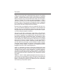
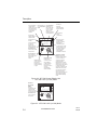
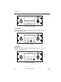
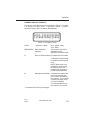
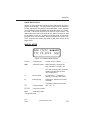
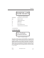
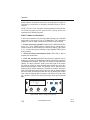
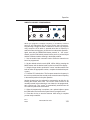
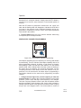
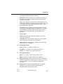
KCU 1051 CONTROL DISPLAY UNIT
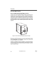
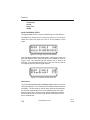
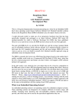
The KCU 1051 Control Display Unit (Figure 2-1) adapts the existing
KHF 950 and KHF 990 High Frequency Radio systems for use with
Automatic Link Establishment, providing the pilot’s display and control interface. Frequency, channel, mode, ALE address, audio gain,
and squelch level selections are entered via its controls. Fault monitoring and fault annunciation are also provided by the KCU 1051.
The KCU 1051 provides the pilot access to 100 manual channels,
100 ALE channels, and 245 ITU channels to interface with maritime
radiotelephone networks. The KCU 1051 uses a liquid crystal display
to show frequency, channel, and mode of operation. The manual
and ALE channels can be easily programmed by the pilot on the
ground or in the air, and the nonvolatile memory stores this information even when the system is turned off.
Rev. 0
Dec/96
KHF 950/990 Pilots Guide
2-1
Description
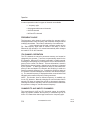
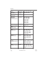
Display
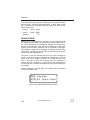
The display screen is capable of displaying 2 lines of 16
(upper or lower case) characters. Information is
presented in formatted pages. The main display pages
are accessed by placing the cursor over the
operations/mode field (ALE) and rotating the VAR knob
until the desired page is displayed. To display a subpage of a main page see Secton III, Operation..
VOLUME knob
The VOLUME knob performs two functions.
Rotate the VOLUME knob to control the
audio output level. Push the VOLUME knob
to the in position to apply power to the unit or
pull the VOLUME knob to the out position to
remove power from the unit.
B
VOL
VAR knob
The VAR knob performs two functions.
Rotate knob to vary data under cursor.
Toggle the momentary switch. VAR knob
to the in position to select CHAR cursor
mode and then toggle again to select
FIELD cursor mode.
HF ALE
SQL
OOOO
Scan 100RM
ALE15CHARADDRESS
SCAN
MSG
CLR
CRSR
VAR
ENT
PUSH
ON
PUSH
CHAR
SQUELCH knob
Rotate SQUELCH
knob to control
the squelch
threshold level.
CURSOR knob
Rotate CURSOR knob to move
cursor from one field to next
field or one character to next
character when in CHAR MODE.
MSG key
The MSG key displays
the message page
where system
messages and ALE
AMDs can be reviewed
SCAN key
The SCAN key starts and
stops scanning and it causes
the radio to hang-up from an
ALE link. The SCAN key can
also be used to abort an
initiated call.
ENT key
Pressing the ENT key
stores changes made
to the cursored field.
CLR key
By pushing the CLR
key you can cancel
changes made by the
operator or exit the
programming page.
Figure 2-1 KCU 1051 Control Display Unit
2-2
KHF 950/990 Pilots Guide
Rev. 0
Dec/96
Description
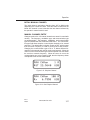
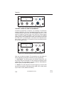
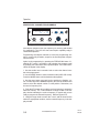
KFS 594 CONTROL DISPLAY UNIT
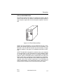
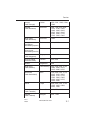
The KFS 594 (Figure 2-2) provides the pilot with access to 19 programmable channels plus a full 280,000 operating frequencies in the
2.0 to 29.9999 MHz range. In addition, all 245 ITU maritime radiotelephone network (public correspondence) channels have been stored
in nonvolatile memory along with the appropriately paired transmit
and receive frequencies. Thus, to call up a radiotelephone channel,
the pilot need only select “423” for WOM in Ft. Lauderdale, Fla., for
example, rather than having to program 4425.6 kHz as the transmit
frequency and 4131.2 kHz as the receive frequency (see WOM channel/frequency chart, Figure 7-3). The KFS 594 is a miniature Gold
Crown III style control display unit which uses electronic gas discharge readouts to display frequency and channel information. All
necessary controls for operation of the KHF 950/990 system, including programming of all preset channels, are on the KFS 594.
The 19 channels can be easily programmed by the pilot on the
ground or in the air, and the nonvolatile memory stores this information and the 245 ITU maritime radiotelephone channels even when
the system is turned off.
Rev. 0
Dec/96
KHF 950/990 Pilots Guide
2-3
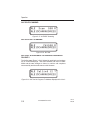
Description
Pilot programmed
channel number
appears in this area
of the display when
using one of the 19
programmable
channels.
Gas discharge
readouts display all
frequencies and
preset channel
numbers.
Last for digits (kHz)
of operating
frequency are
display in this area
of the display with
EMISSION MODE
switch in LSB*, USB
or AM position.
With EMMISSION
MODE switch in
LSB*, USB or AM
position, the first
one or two digits
(MHz) of the
operating frequency
are displayed here.
Dash indicates unit
is in the PROGRAM
MODE.
Smaller gas
discharge
characters display
transmit indication.
Photocell dims
display
automatically.
1
CH
12 - 31
1231
HF
VOL
SQ
OFF
AM
USB
M
T H
X Z
K
H
Z
S
T
A3J TEL
A3A
LSB
OFF/VOLUME knob
(inner concentric)
turns system on and
adjusts audio
volume.
EMMISSION MODE
switch (outer
concentric) selects
lower sideband
(LSB), AM modes,
and a choice of
either A3J or A3A in
maritime
radiotelephone
network channels.
SQUELCH knob
(outer concentric)
helps reduce
background noise
when not receiving
a signal.
STO (store) switch
stored displayed
frequency in memory.
When pressed
simultaneously with
microphone push-to-talk
switch, transmits 1,000
Hz "operator attention"
tone as required by
some Canadian
radiotelephone stations.
FREQUENCY/CHANNEL
CONTROL knob (inner
concentric) allows the pilot
to perform a variety of
channel and frequency
changing functions.
Depressing switch causes
flashing "cursor" to move to
the digit that the pilot desires
to change. Appropriate
frequency or channel is then
selected with rotary action.
This switch also serves as
the clarifier function to
adjust receive frequency and
improve speech quality in
single sideband operating
mode.
Figure 2-2 KFS 594 Control Display Unit
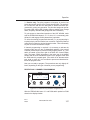
KFS 594 in A3J (or A3A) Mode
KFS 594 in
A3J (or A3A)
MODE
Mairitime
radiotelephone ITU
channel number
appears in this area
of the display when
EMISSION MODE
switch is in A3J or
A3A position.
1
CH
M
H
Z
2236
HF
VOL
OFF
SQ
USB
AM
K
H
Z
S
T
A3J TEL
A3A
LSB
Figure 2-3 KFS 594 in A3J (or A3A) Mode
2-4
KHF 950/990 Pilots Guide
Rev. 0
Dec/96
Description
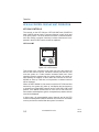
KCU 951 CONTROL DISPLAY UNIT
The KCU 951 (Figure 2-4) provides the pilot access to 99 programmable channels plus a full 280,000 operating frequencies in the 2.0 to
29.9999 MHz range. It provides semi-duplex capability through the 99
programmable channels to interface with maritime radiotelephone
networks. A Dzus rail-mounted control display unit, the KCU 951,
uses electronic gas discharge readouts to display frequency, channel
and mode of operation. All necessary controls for operation of the
KHF 950/990 system, including programming of all preset channels,
are on the KCU 951. The 99 channels can be easily programmed by
the pilot on the ground or in the air, and the nonvolatile memory
stores this information even when the system is turned off.
Gas discharge
readouts display all
frequncies and
preset channel
numbers.
Smaller gas
discharge
characters display
emmision mode,
transmit indicator
and program mode
indication.
Photocell
dims display
automatically.
EMMISSION MODE
switch selects lower
sideband (LSB
where aproved),
upper sideband
(USB) or AM
modes.
ı
FREQ/CHAN
(frequency/channel)
switch selects either
direct tuning or
preset channel
operation.
HF
12345.6 99
LSB
AM USB
TX
FREQ KHZ
PGM
MODE
FREQ CHAN
CHANNEL
PULL
CLARIFIER
SQUELCH
OFF
VOLUME
STO
SQUELCH knob
helps cut out
background noise
when not
receiving a signal.
Concentric
Frequency/Channel
knobs set frequency
or select preset
channel.
OFF/VOLUME
knob turns
system on and
adjusts audio
volume.
CLARIFIER knob adjusts receive frequency to
improve speech quality in a single sideband
operating mode. Use of this control is only
required when station-to-station frequency
difference is significant.
PGM
PGM (program)
switch permits pilot
to change frequncy
and emission mode
of preset channel.
STO (store)
switch stores
displayed
frequency and
emmission mode
in memory.
Figure 2-4 KCU 951 Control Display Unit
Rev. 0
Dec/96
KHF 950/990 Pilots Guide
2-5
Description
KHF 950 REMOTE UNITS
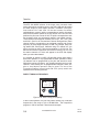
KAC 952 POWER AMPLIFIER/ANTENNA COUPLER
The KAC 952 Power Amplifier/Antenna Coupler unit (Figure 2-6) is
mounted near the HF antenna to optimize transmission efficiency.
The KAC 952 is all solid-state and can be mounted outside the aircraft pressure vessel for operation at any altitude up to 55,000 feet.
The power amplifier in the KAC 952 amplifies the signal from the KTR
953 Receiver/Exciter into a 150 watt peak envelope power (PEP)
transmitted signal in single sideband operation and 35 watts in AM
operation.
Figure 2-5 KAC 952 Power Amplifier/Antenna Coupler
Because the KHF 950 operates over such a broad frequency range
(2.0 to 29.9999 MHz), it is impossible to optimize the actual aircraft
HF antenna length for each frequency.
Instead, by changing its electrical impedance, the automatic antenna
coupler in the KAC 952 tunes the antenna to each frequency, making
the antenna appear to the transmitted signal as though it were the
optimum physical length.
2-6
KHF 950/990 Pilots Guide
Rev. 0
Dec/96
Description
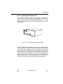
KTR 953 RECEIVER/EXITER
The KTR 953 remote unit (Figure 2-6) contains the receiver and the
exciter for the KHF 950. The exciter is a transmitter which produces a
very low power signal which is fed to the power amplifier in the KAC
952.
B
KTR 953
Figure 2-6 KTR 953 Receiver/Exiter
NOTE: Only the KTR 953-01,11,41,53 (KPN 064-1015-01) is compatible with standard SELCAL decoder units (not furnished). The
KTR 953-01 and the SELCAL decoder are both necessary to obtain
SELCAL operation. See page 19 for additional information on SELCAL.
NOTE: The KHF 950 is designed for continuous duty cycle (transmit)
at 150 watts PEP for voice transmission on upper sideband (USB).
On all other type transmissions, the unit will operate continuously;
however, after an extended period of transmission the power will
begin to back down to protect the power amplifier from overheating.
The exact time required depends on the ambient temperature. For
example, after seven minutes transmission in the AM Mode the
power is approximately 1/3 of normal power output. A duty cycle of 3
minutes on and 3 minutes off will insure maximum power output.
Rev. 0
Dec/96
KHF 950/990 Pilots Guide
2-7
Description
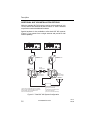
ADDITIONAL KHF 950 INSTALLATION OPTIONS
While the standard KHF 950 system requires a wire antenna of only
10 feet, shorter wire antennas as well as “shunt” or “notch” antennas
may also be tuned with additional hardware.
Special hardware is also available to allow dual KHF 950 systems
(Figure 2-7) to operate from a single antenna and provide a dual
receive capability.
*KCU 951 Control Display Unit
ı
*KCU 951 Control Display Unit
ı
HF
12345.6 99
LSB
AM USB
FREQ KHZ
TX
PGM
MODE
LSB
FREQ CHAN
CHANNEL
AM USB
TX
FREQ KHZ
PULL
CLARIFIER
HF
12345.6 99
PGM
MODE
FREQ CHAN
CHANNEL
PULL
SQUELCH
OFF
VOLUME
CLARIFIER
STO
B
KTR 953
SQUELCH
OFF
VOLUME
PGM
STO
KTR 953
Receiver/Exciter
B
KTR 953
PGM
KTR 953
Receiver/Exciter
KA 158
Bridging Amps
KAC 952
Power Amplifier/
Antenna Coupler
*A KCU 1051Control Display Unit or a miniature
KFS 594 Control Display Unit with its associated
KA 594 adapter may be substituted for the
KCU 951 Control Display Unit.
KAC 952
Power Amplifier/
Antenna Coupler
Aircraft
HF Antenna
KA 160 Antenna Changeover Unit
(For long wire antennas).
or
KA 162 Antenna Changeover Unit
with external capacitor
(For shunt or short wire antennas).
Figure 2-7 Dual KHF 950 System Configuration
2-8
KHF 950/990 Pilots Guide
Rev. 0
Dec/96
Description
SINGLE KHF 950 SYSTEM CONFIGURATION (SHUNT OR
SHORT WIRE ANTENNAS)
*KCU 951 Control Display Unit
ı
HF
12345.6 99
LSB
AM USB
FREQ KHZ
TX
PGM
MODE
FREQ CHAN
CHANNEL
PULL
CLARIFIER
SQUELCH
OFF
VOLUME
STO
B
KTR 953
PGM
KTR 953
Receiver/Exciter
Aircraft
HF Antenna
KAC 952
Power Amplifier/
Antenna Coupler
KA 161 Antenna
External Capacitor Unit
*A KCU 1051Control Display Unit or a miniature
KFS 594 Control Display Unit with its associated
KA 594 adapter may be substituted for the
KCU 951 Control Display Unit.
Figure 2-8 Single KHF 950 System Configuration
(Shunt or Short Wire Antennas)
Rev. 0
Dec/96
KHF 950/990 Pilots Guide
2-9
Description
KHF 990 REMOTE UNITS
KAC 992 PROBE/ANTENNA COUPLER
The KAC 992 Probe/Antenna Coupler (Figure 2-9) is a combined
Whip Antenna and Coupler designed to automatically match the
impedance of the antenna to 50 ohms over the full frequency range
of 2.0 to 29.999 MHz. The KAC 992 Coupler is hermetically sealed,
so may be mounted either totally external or with coupler section
mounted internally and the antenna protruding through a clearance
hole in the aircraft skin.
Figure 2-9 KAC 992 Probe/Antenna Coupler
2-10
KHF 950/990 Pilots Guide
Rev. 0
Dec/96
Description
KTR 993 RECEIVER/EXITER/AMPLIFIER
The KTR 993 (Figure 2-10) HF Transceiver contains the
receiver/exciter, RF power amplifier, Lowpass filters, and control circuitry necessary for generation of SSB and AME signals. It is capable of 150 watts PEP output on any of 280,000 frequencies from 2 to
29.9999 MHz.
ı
REMO
TE
D.C. PO
KTR 993
WER
ANTE
NNA
Figure 2-10 KTR 993 Receiver/Exiter/Amplifier
NOTE: The KHF 990 is designed for continuous duty cycle (transmit)
at 150 watts PEP for voice transmission on upper sideband (USB).
On all other type transmissions, the unit will operate continuously;
however, after an extended period of transmission the power will
begin to back down to protect the power amplifier from overheating.
The exact time required depends on the ambient temperature. For
example, after seven minutes transmission in the AM Mode the
power is approximately 1/3 of normal power output. A duty cycle of 3
minutes on and 3 minutes off will insure maximum power output.
Rev. 0
Dec/96
KHF 950/990 Pilots Guide
2-11
Description
SINGLE KHF 990 SYSTEM CONFIGURATION
*KCU 951 Control Display Unit
ı
HF
12345.6 99
LSB
AM USB
TX
FREQ KHZ
PGM
MODE
FREQ CHAN
CHANNEL
PULL
CLARIFIER
SQUELCH
OFF
VOLUME
STO
PGM
KTR 993
Receiver/Exciter/Amplifier
ı
REMO
TE
Aircraft
HF Antenna
KTR 993
D.C. POW
ER
ANTENN
A
KAC 992
Probe/Antenna Coupler
*A KCU 1051Control Display Unit or a miniature
KFS 594 Control Display Unit with its associated
KA 594 adapter may be substituted for the
KCU 951 Control Display Unit.
Figure 2-11 Single KHF 990 System Configuration
2-12
KHF 950/990 Pilots Guide
Rev. 0
Dec/96
Operation
SECTION III
OPERATING THE KHF 950/990
KHF 950/990 GENERAL OPERATING INFORMATION
PREFLIGHT INSPECTION
During preflight walk around inspection, it’s important to check the HF
antenna for structural integrity. Long wire antennas may be used with
the KHF 950, and these can be damaged by ice accumulation in
flight or broken by improper aircraft ground handling or fueling operations.
A ground check of the KHF 950/990 is advisable, particularly if it is
going to be the primary source of contact with Air Traffic Control during over water flights. (It may be advisable to consider the operational
benefit of installing dual KHF 950 radios when HF communications
are the primary source of contact with Air Traffic Control. A second
unit would provide a backup and a means of monitoring other HF services while the first radio is tuned to an ATC frequency.)
To check for proper antenna tuning, allow the KHF 950/990 to warm
up until the display becomes active (up to two minutes), select an
authorized frequency and press the microphone key. When using a
KCU 1051, “TUNE IN PROGRESS” will be displayed if the channel
had not been previously tuned. When tuning stops, the frequency
display reappears. If a fault is indicated, refer to the section on Fault
Indication in the pilots guide.
NOTE: When using the KCU 951 or the KFS 594, the TX annunciation should flash and the frequency display blank as the antenna coupler tunes the antenna. When the tuning sequence is complete the
TX stops flashing and the frequency display reappears. If the TX fails
to stop flashing refer to the section on Fault Indication in this pilot’s
guide.
To check for proper operation of the system, transmit a radio check
on an authorized frequency. Make sure you can transmit and receive,
using a frequency which is suitable for the time of day.
NOTE: The warm up period is for a crystal oven to heat up which
assures an extremely high degree of frequency stability under varying environmental conditions.
Rev. 0
Dec/96
KHF 950/990 Pilots Guide
3-1
Operation
CAUTION: When performing a ` radio check on the ground,
make certain that all personnel are clear of the HF antenna
before transmitting. SERIOUS RF BURNS CAN RESULT FROM
DIRECT CONTACT WITH THE ANTENNA OR ANTENNA TERMINAL WHEN THE SYSTEM IS TRANSMITTING.
ANTENNA TUNING
When using a KCU 1051 control display unit, the antenna coupler
tune information is stored in non-volatile memory. This means that
retunes are required only when new frequencies are entered into the
channel non-volatile memory. For semi-duplex channels both the
receive and transmit frequency is tuned to provide optimum performance.
When using a KCU 951 or a KFS 594 the antenna coupler retunes
the antenna under the following conditions:
1. When the system is first turned on (and warmed up) and the mic
key is pressed.
2. When a new channel or frequency is selected and the mic key is
pressed. Always initiate a tuning sequence after selecting a new frequency or channel. A tuned antenna improves receiver performance.
3. When an existing channel or frequency is being used while the
unit senses an improper match and the mic key is pressed.
The antenna coupler is always utilized when transmitting (regardless
of mode) and while receiving in the simplex mode (after mic key is
pressed for tuning). The antenna coupler is bypassed during receive
when operating in semi-duplex or receive-only channelized operation.
The system is then functioning as a receiver connected directly to the
HF antenna.
FAULT INDICATION
When using a KCU 1051, if the system detects a fault, a flashing “M”
appears in the upper right corner of the display, and a fault message
is displayed on the second line. The fault message reads “High
VSWR” if there is an antenna problem, otherwise it reads “Fault see
MSG pg”. If connected, the Remote light also annunciates. The fault
messages can be viewed on the message page by pressing the
MSG key. If a High VSWR fault occurs, key the microphone to cause
the automatic antenna coupler to begin a new tuning cycle to clear
the fault.
3-2
KHF 950/990 Pilots Guide
Rev. 0
Dec/96
Operation
Using the KCU 951 or KFS 594, if the system detects a fault during
transmission or during the tuning of the antenna coupler, the frequency digits on the display begin to flash. Simply key the mic and the
automatic antenna coupler begins a new tuning cycle to clear the
fault.
TUNING FAULTS
If the antenna coupler is unable to find an acceptable
frequency/antenna match, the fault indication continues at the end of
the tuning cycle. If repeated antenna tuning cycles fail to clear the
fault indication from the display, there is probably an equipment malfunction.
KHF 950/990 CONTROLS-GENERAL
Operating the KHF 950/990 requires that the pilot first determine the
correct mode to match the ground station, whether it be upper sideband (USB), lower sideband (LSB), or AM. Correct mode selection is
essential for successful contact with a ground station. Most stations
use USB mode, but some continue to use AM. Also, the pilot must
determine whether simplex, semi-duplex or receive-only frequency
operation is required to match the operation of the desired ground
station.
THERE ARE SEPARATE OPERATING SECTIONS ON EACH OF
THE CONTROL DISPLAY UNITS. READ ONLY THE SECTION
WHICH PERTAINS TO THE CONTROL DISPLAY UNIT YOU HAVE
INSTALLED WITH YOUR KHF 950/990.
Rev. 0
Dec/96
KHF 950/990 Pilots Guide
3-3
Operation
KCU 1051 CONTROL DISPLAY UNIT OPERATION
This section describes the KCU 1051 Control Display Unit controls
and display. The ALE database is preloaded as described in Section
XII.
KCU 1051 GENERAL OPERATING INFORMATION
KCU 1051 CONTROL DESCRIPTION
The controls on the KCU 1051 CDU are: PUSH/ON control, VOL
knob, SQUELCH knob, PUSH CHAR, CURSOR knob, VAR knob,
CLR key, ENT key, SCAN key, MSG key,
PUSH ON/VOL
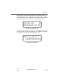
This control (Figure 3-1) turns the system on and off and controls volume. Push the VOL knob to the in position to apply power to the unit
or pull the VOL knob to the out position to remove power from the
unit. Rotate the VOL knob to control the audio output level.
B
VOL
HF ALE
SQL
OOOO SSSSSSSSSRM
1234567890123456
SCAN
MSG
CLR
CRSR
VAR
ENT
PUSH
ON
PUSH
CHAR
Figure 3-1 Push ON/VOL
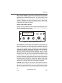
SQUELCH (SQL)
Squelch (Figure 3-2) is set by rotating the SQL knob counterclockwise until background noise is heard, and then turning it clockwise
until background noise is eliminated or just barely audible. When
using ALE, the squelch normally is turned off because ALE turns off
the audio until a call is received.
3-4
KHF 950/990 Pilots Guide
Rev. 0
Dec/96
Operation
B
VOL
HF ALE
SQL
OOOO SSSSSSSSSRM
1234567890123456
SCAN
MSG
CLR
CRSR
VAR
ENT
PUSH
ON
PUSH
CHAR
Figure 3-2 Squelch Control
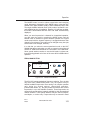
CURSOR (CRSR)
The cursor is moved by rotating the CRSR knob (Figure 3-3). The
cursor moves from one field to the next field when in the field cursor
mode. The cursor moves from one character to the next character
when in the character cursor mode.
B
VOL
HF ALE
SQL
OOOO SSSSSSSSSRM
1234567890123456
SCAN
MSG
CLR
CRSR
VAR
ENT
PUSH
ON
PUSH
CHAR
Figure 3-3 Cursor Control
VAR/PUSH CHAR
The VAR knob (Figure 3-4) performs two functions. Rotate the VAR
knob to change data under the cursor. Pressing the VAR knob toggles the cursor between field and character modes. In field cursor
mode the cursor covers the entire field. In character cursor mode the
cursor covers a single digit, or character, within a field.
Rev. 0
Dec/96
KHF 950/990 Pilots Guide
3-5
Operation
B
VOL
HF ALE
SQL
OOOO SSSSSSSSSRM
1234567890123456
SCAN
MSG
CLR
CRSR
VAR
ENT
PUSH
ON
PUSH
CHAR
Figure 3-4 Var Control
CLEAR (CLR)
The CLR key (Figure 3-5) cancels changes made to the active field or
exits a programming page..
B
VOL
HF ALE
SQL
OOOO SSSSSSSSSRM
1234567890123456
SCAN
MSG
CLR
CRSR
VAR
ENT
PUSH
ON
PUSH
CHAR
Figure 3-5 CLR key
ENTER (ENT)
The ENT key (Figure 3-6) stores changes made to the active field, or
activates the selected mode.
B
VOL
HF ALE
SQL
OOOO SSSSSSSSSRM
1234567890123456
SCAN
MSG
CLR
CRSR
VAR
ENT
PUSH
ON
PUSH
CHAR
Figure 3-6 ENT key
3-6
KHF 950/990 Pilots Guide
Rev. 0
Dec/96
Operation
B
VOL
HF ALE
SQL
OOOO SSSSSSSSSRM
1234567890123456
SCAN
MSG
CLR
CRSR
VAR
ENT
PUSH
ON
PUSH
CHAR
Figure 3-7 MSG Key
MESSAGE (MSG)
The MSG key (Figure 3-7) displays the message page where system
messages, and ALE, digital messages (AMDs) can be reviewed.
The MSG key displays the message page where system messages,
ALE AMDs, or modem messages can be reviewed.
SCAN
The SCAN key starts and stops scanning and it causes the radio to
hang-up from an ALE call. The SCAN key can also be used to abort
an initiated call.
B
VOL
HF ALE
SQL
OOOO SSSSSSSSSRM
1234567890123456
SCAN
MSG
CLR
CRSR
VAR
ENT
PUSH
ON
PUSH
CHAR
Figure 3-8 Scan Key
Rev. 0
Dec/96
KHF 950/990 Pilots Guide
3-7
Operation
KCU 1051 DISPLAY AND CONTROL OPERATION
This section describes the user interface to the HF system.
This is a brief explanation of the operation of the KCU 1051 display
and controls used to enter the manual channel and ALE databases
(Figure 3-9).
B
VOL
HF ALE
SQL
ALE
MsgRcv 22DM
<MD MSG DSPLAY
SCAN
MSG
CLR
CRSR
VAR
ENT
PUSH
ON
PUSH
CHAR
Figure 3-9 KCU 1051 Front Panel Controls
And Indicators
DISPLAY
The display has 2 lines of 16 characters. Both upper and lower case
letters can be displayed. The use of upper and lower case letters
makes some abbreviations easier to read, for example “MSGRCV”
could be “MsgRcv”
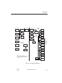
PAGES
The display is arranged in pages. A page is a presentation of specific
data in an organized format. Figure 3-10 shows the page organization. There are four top level pages; ALE, SEND, MAN and SYS.
ALE mode is enabled on the ALE and SEND pages. The MAN (manual) page allows the manual database of 100 channels, to be
reviewed, entered, and used for receive and transmit. The ALE
channels can also be reviewed and used for receive and transmit on
the manual page. However, the ALE database can be programmed
only in the sub-pages below the SYS (system) page. On the System
Page, placing the cursor over the top right field allows selection of
subsequent system pages.
3-8
KHF 950/990 Pilots Guide
Rev. 0
Dec/96
Operation
Normal Operation
Bold= Cursorable field
ALE scan 100R
DUSTOFF6
1
ALE idle state
scanning or single
channel
4
ALE Calling 12T
DUSTOFF6
ALE call to address
on second linel
4
ALE Linked 12R1
DUSTOFF6
Linked to address
on second line
SEND Message 10
STOP AND
2
MAN ChMan 23R
R&T 23.3950 USB
Send AMD msg
5
SYS Test
ENT to Start
2
2
TEST: Passes
CLR to exit
Sound with
self address on
second line
2
3
SYS Program
} Messages
SEND LQA
DUSTOFF
Del_RX 3
RETURNTO
5
} Messages
| Operation
| Channel
{ Address
Copy_RX 2
ToTx 3
2
Perform LQA
exchange with
address on second line
SYS LQAscore
ENT to review
5
2
4
ALE MsgRcv 5D
RETURNTO
Receiving AMD
Msg scrolls across
second line
Bright Panel
ENT to set Max
4
ALE SoundR5D
BRAVO4
Sound received from
address on second line
} ActvLim
| ScnRate
| Sound
{ CallTime
} Auto Sound
| LQA in call
| Message Rx
| Anycall Rx
| Allcall Rx
| Wildcard
{ Roll Over
any page
MSG key
2
4
ALE SoundT23T
KR1
Intervals
} ActvLim 5Min
Enables
} AutoSound ON
LQA scores
| displayed
Mode selection in ALE
ALE to SEND allowed
in idle & linked states
Edit_TX10
MISSION
Rev_RX 3
RETURNTO
SYS RevNum
SWMOD RR/VV
SEND SoundAS
KR1
2
Database programming and Built in Test
1
1
ALE-channel 11
R&T 23.4560 USB
ChGrp 23S ADD 32
12122431
MSG msg-type
message shown
Sounding on channel 23
using address on
second line
ScanList
Use ChGrp 1S
Tune All ? YES
Caution HF xmit
Notes:
1. Operator change to Operation/Mode field
2. Operator change to State/Selection-Category field
3. Operator change to sub page selection field(second line)
4. ALE state change, automatic or operator selected
5. ENT key pressed
Need Tune ###
Completed ###
Addr Self 20
} KR1
ClearTunes ? NO
Sets all untuned
Figure 3-10 Page Organization
Rev. 0
Dec/96
KHF 950/990 Pilots Guide
3-9
Operation
DATA STORE AND RECALL WITH THE CLR AND ENT KEYS.
The CLR and ENT keys are used for data entry. The ENT key causes the changes made to the field under the cursor to be stored. The
CLR key can be used to restore the original value of the field until the
ENT key is pressed. The changes to a field are also stored when the
operator moves the cursor to another field.
CLR KEY
1. After data has been entered but before the ENT key is pressed
or the cursor is movedfrom the field:
A. If the cursor is in the character cursor mode and the field
contains ASCII strings, such as an ALE address or AMD
message:
The first press of the CLR key clears the data field from
the point of the character cursor to the end of the field.
The second press of the CLR key restores the original
data.
The third press of the CLR key exits the character cursor
mode.
B. For the field cursor the first press of the CLR key restores the
original data.
2. The CLR key is also used to exit from a page and remove the
cursor. After satisfying the CLR key actions above, the CLR key
returns you to the idle page. The next press of the CLR key removes
the cursor, if allowed.
ENT Key
As the operator progresses through the menus the ENT key or the
CRSR knob can be used to move the cursor to the next field or item.
The ENT key provides a benefit of leading the operator through a list
of associated parameters. After the operator changes a field, pressing the ENT key indicates acceptance of the change. The cursor
moves to the next field or a parameter is displayed on the bottom line
to show a response to this action. For example, on the
Operation/Interval page pressing the ENT key stores the change to
the current interval and displays the next interval parameter, if there
is one. Using the ENT key instead of the CRSR knob prevents the
operator from accidentally skipping a field, since the CRSR knob
moves the cursor rapidly. Using the operation/interval page as an
3-10
KHF 950/990 Pilots Guide
Rev. 0
Dec/96
Operation
example, the sequence can be described as follows:
1. The operation / interval page is displayed.
2. Move the cursor over the interval value field
3. Use the VAR knob to change the interval.
If the data is correct, skip this step
4. Push the ENT key to accept the interval value.
5. The next interval is displayed.
Repeat Steps 3 through 4 until all intervals
have been reviewed or modified.
MICROPHONE KEY OPERATION.
In the Manual mode the microphone key controls the normal talk-listen transitions of push-to-talk operation
In the ALE mode the response to microphone key is dependent on
the current ALE state. If ALE is idle (not in the process of sending or
receiving a call) then activation of the microphone key initiates a call
to the ALE address currently displayed on the screen. The
channel(s) used for the ALE call depends on the ALE channel state
which can be either scanning or single channel. In the ALE scanning
state the call is attempted on the channels selected automatically by
LQA criteria until a link is established or all channels on the list have
been tried. In the ALE single channel state the call is initiated on the
active channel only . If a channel is not tuned, then an automatic tuning sequence occurs the first time a transmit is attempted on the
untuned channel.
In the ALE linked state the microphone key controls the normal talklisten transitions of .microphone key operation. The ALE linked state
commences when the audible alert is given, and terminates when link
termination occurs and the radio returns to the ALE idle state.
OPERATOR ALERTS
There are three types of operator alerts, audible alert, Message flag,
and the Remote Lamp. These alerts are used to inform the operator
of messages, states, or faults that require the operators attention.
The Audible Alert is a short burst of tones (similar to a ringing telephone) on the audio output. The Message flag is a flashing “M” on
the display. The Remote Lamp is a discrete output that can be connected to a remote mounted lamp. The table below shows the conditions that activate these alerts.
Rev. 0
Dec/96
KHF 950/990 Pilots Guide
3-11
Operation
Source
Message Flag
“M”
Remote Lamp
Audible Alert
ALE Page State
AMD message received
yes
yes
yes
MsgRcv
Sound received
yes
no
no
SoundR
Linked
ALE link
no
yes
yes
Faults
yes
*some
no
* Remote Lamp not set for VSWR fault
Table 3-1 Operator Alert Indications
The Message flag is reset when the Message page is viewed. The
message flag is also reset for AMD messages and Sounds if the
ENT, CLR, or SCAN key is pushed while the associated state is displayed on the ALE page. The Remote Lamp discrete is reset on any
operator action; microphone key, knob or key
3-12
KHF 950/990 Pilots Guide
Rev. 0
Dec/96
Operation
COMMON DISPLAY FORMATS
The top line of the display has the format shown (Figure 3-11) below.
It is divided into three fields 1) Operation / Mode, 2) State /
Selection-Category,Receive State 3) Message flag.
OOOO SSSSSSSSSRM
1234567890123456
Figure 3-11 Display Format
OOOO
* Operation / Mode
ALE, SEND, MAN,
SYS, MSG.
SSSSSSSSS
State /SelectionCategory
The format of this field is
dependent on the
Operation / Mode selected.
R
Receive/Transmit State R indicates Receive Mode
T indicates Transmit Mode
D indicates Detecting ALE
tone
NOTE: When there is no
message or untuned flag,
this field moves to the
message flag location to
provide better readability.
M
Message/Untuned flag A flashing M indicates that
there is a message that
has not been reviewed by
the operator. This could be
a system message (fault),
or an ALE message.
A U indicates that the current channel is not tuned.
* cursorable field in all top level pages
Rev. 0
Dec/96
KHF 950/990 Pilots Guide
3-13
Operation
OPERATION / MODE FIELD
The Operation / Mode field controls which page is displayed. There
are four top level pages accessible through the Operation / Mode
field: MAN, ALE, SEND, SYS. The MSG page is not selectable in the
Operation / Mode field, it is accessed by pushing the MSG key.
Changes to the Operation / Mode field are reflected in the rest of the
display immediately.
STATE / SELECTION-CATEGORY FIELD
The State / Selection-Category field provides different functions
based on the current page. This field is subdivided into smaller fields
on most pages. For some pages it displays the system state, for
example scanning or single channel. On other pages this field is
used to select from a list of available selections.
RECEIVE / TRANSMIT STATE
The receivel transmit state has three states:
R
indicates the radio is in the receive state.
T
indicates the radio is in the transmit state.
D
indicates the radio is receiving ALE tones.
MESSAGE / UNTUNED FLAG
A flashing M is displayed when there is a new message for the operator. To review the message the operator selects the message page
by pushing the MSG key. A U is displayed when the current channel
is not tuned. An untuned warning message is also displayed on the
message page.
SECOND LINE OF DISPLAY
The second line of the display is used as a window into a list of items
on most pages. This window can be scrolled up and down a list with
the CRSR knob or the next item in the list can be displayed by pushing the ENT key.
Temporary overlays also are displayed on the second line. Some
overlays are displayed for a few seconds then the line returns to the
original display. Other overlays remain on the display until removed
by pushing the CLR key. There are some program on which that
overlays are not displayed. Changes to volume and squelch are
temorarily displayed in overlays. Faults are displayed in overlays and
on the message page.
3-14
KHF 950/990 Pilots Guide
Rev. 0
Dec/96
Operation
LARGE DATA FIELDS
Arrows on the second line indicate that the data within the field is
larger than the display.. For items that are longer than 16 characters,
left and right arrows are used to indicate that there is more data that
can be displayed using the CRSR knob when the cursor is in character mode. The arrows can point up or down for a list of items. The
down arrow means this is the top of the list, and the up arrow is used
for the bottom of the list. A double arrow that points up and down
indicates there are parameters above and below the current one.
The }{ symbols are used to represent up and down arrows on the
pages below.
MANUAL MODE
MAN CCCCC ####RM
TTT FF.FFFF
MOD
Figure 3-12 Manual Mode Displays
CCCCC
* channel type
ChMan, ChITU, ChALE, _ _ _ _ _,
####
* channel number
MAN channels 1 through 100
ALE channels 1 through 100
ITU 245 fixed frequency channels
channel numbers 401 to 2510
(non consecutive)
R
receiver state
R = Receive T = Transmit D
flashing = Detecting ALE tones
M
message flag
Flashing M indicates an unread
message.
U indicates channel is untuned
TTT
* communication
FF.FFFF
* frequency in MHz
MOD
* modulation type
R&T, Rx, Tx
* Cursorable fields
Rev. 0
Dec/96
KHF 950/990 Pilots Guide
3-15
Operation
In manual operation mode four types of channels are available:
• 1 frequency agile
• 100 programmable manual channels
• 100 ALE channels
• 245 fixed ITU channels
FREQUENCY AGILE
The frequency agile channel mode provides the operator with a
scratch-pad area to make frequency and modulation changes without
modifying stored data. This mode is indicated by five underscores
“ _ _ _ _ _ “ in the channel type field and a channel number of zero
(0). The frequency agile mode is entered in two ways, it can be
selected by the operator or it is entered automatically when changes
are made to ITU or ALE channels.
ITU CHANNEL OPERATION
The ITU channels are stored in permanent memory and cannot be
changed by the operator. Tunes are not permanently stored for the
ITU channels. When an ITU channel is selected it is initially untuned.
Pressing the microphone key tunes both the receive and transmit frequency for the current ITU channel. This tune information is saved in
RAM until the channel number, channel type or frequency is changed
by the operator. To allow the operator to listen on the transmit frequency of the semi-duplex ITU channels, the SCAN key is used as a
receive on transmit frequency key. Pressing the SCAN key when an
ITU channel is selected changes the receiver to the transmit frequency. The transmit frequency is displayed and the communication field
indicats that the transmit frequency is being monitored.
NOTE: This function, listen on transmit frequency, is available only
for the ITU channels. Manually changing the communication field to
transmit (TX) does not change the receiver to the transmit frequency.
Selecting the transmit frequency with the communication field allows
the operator to change or view the transmit frequency.
CHANGES TO ALE AND ITU CHANNELS
The stored data for ALE and ITU channels cannot be modified.
When the operator modifies the frequency or modulation type of an
ALE or ITU channel the channel type reverts to the ‘frequency agile’.
3-16
KHF 950/990 Pilots Guide
Rev. 0
Dec/96
Operation
INITIAL MANUAL CHANNEL
The initial channel used when changing from ALE to MAN mode
depends on the current ALE state. If the ALE state is linked, then the
linked ALE channel is used, otherwise the last channel selected by
the operator in manual mode is used.
MANUAL CHANNEL ENTRY
Changes made to the 100 manual channels are stored in nonvolatile
memory. The frequency, modulation type, and communication type
are programmable. The frequency modulation and communication
type are modified with the CRSR and VAR knobs. The communication type field allows simplex or semi-duplex channels to be entered
and used. The default state is simplex, shown as R&T, which means
that the same frequency is used for both receive and transmit.
Changing the communication type to Rx or Tx allows different frequencies to be entered and used for receive and transmit. When the
cursor is on the communication type field the operator can view either
the receive or transmit frequency. When the cursor is not on the
communication type or the frequency field, then the frequency shown
corresponds to the current transmit state.
MAN ChMan
R&T 22.5640
1 R
USB
Figure 3-13 Simplex Channel
MAN ChMan
100 R
Rx
6.7550
USB
Figure 3-14 Semi Duplex Channel
Rev. 0
Dec/96
KHF 950/990 Pilots Guide
3-17
Operation
MAN ChITU 2510 R
Rx
26.1720
A3A
Figure 3-15 Manual ITU Channel
This display indicates that the unit is in receive on ITU channel 2510.
Rx is indicated because the receive and transmit frequencies are different.
ALE MODE
The operator can initiate ALE calls and start and stop scanning while
in this mode. While in the ALE mode the radio can receive ALE calls,
AMD messages and sounds from other ALE radios. ALE mode has
the following states :
• CH:
Idle not scanning
• Scan
Idle scanning
• Linked
Linked with single ALE address call type
• NETlnk
Linked with an ALE network call type
• ALLlnk
Linked with an ALL call type
• ANYlnk
Linked with an ANY call type
• WLDlnk
Linked with a wild card call type
• GRPlnk
Linked with a Group call type
• MsgRcv
Receiving an AMD message
• Callng
Performing an ALE call
• SoundR
Receiving a sound from an ALE radio.
• SoundT
Transmitting a sound
• Pollng
LQA (Link Quality Analysis) poll in progress
ALE IDLE STATES
The radio has two ALE idle states, scanning and not scanning. The
radio is toggled between these two states by pushing the SCAN key.
The radio is listening for and will respond to ALE calls in either state.
The calling address is selectable on this page. The channel is also
selectable when not scanning. The operator initiates a call by pressing the microphone key. If the radio is scanning an auto-call is per-
3-18
KHF 950/990 Pilots Guide
Rev. 0
Dec/96
Operation
formed. If the radio is not scanning then a call is performed on the
selected channel only.
ALE MODE DISPLAYS
ALE
SSSSSS###RM
1234567890123456
Figure 3- 16 ALE Mode Displays
SSSSSS
state
.
###
* channel number
ALE channels 1 through 100
R
receiver state
R = Receive T = Transmit D flashing = Detecting ALE tones
M
message flag
Flashing M indicates an unread
message.
U indicates that channel is untuned.
line 2
* addr/msg
ALE address or AMD message
* Cursorable fields.
Channel number is cursorable only if not scanning.
Rev. 0
Dec/96
KHF 950/990 Pilots Guide
3-19
Operation
ALE IDLE SCANNING
ALE
Scan
100 R
ALE15CHARADDRESS
Figure 3-17 ALE IDLE Scanning
ALE IDLE NOT SCANNING
ALE
CH:100 R
ALE15CHARADDRESS
Figure 3-18 ALE Idle
ALE CALL IN PROGRESS TO ADDRESS DISPLAYED
ON LINE 2
The Calling state (Figure 3-19) is initiated by pushing the microphone
key or on the SEND page. This state continues until a link is established and the state changes to Linked, or until the call completes
unsuccessfully and the radio returns to the idle state.
ALE Calling 12 T
ALE15CHARADDRESS
Figure 3-19 ALE Call In Progress To Address Displayed On Line 2
3-20
KHF 950/990 Pilots Guide
Rev. 0
Dec/96
Operation
ALE LINKED TO ADDRESS DISPLAYED ON LINE 2
This state indicates that the radio is linked to another ALE radio. The
ALE address listed on the second line (Figure 3-20) is the address of
the other ALE radio or the ALE net or group. An audible alert is generated and the Remote Lamp discrete is set when the link occurs.
The Remote Lamp discrete will be reset on the first activation of the
microphone key or any key or knob action. The operator hangs up
(unlinks) by pressing the SCAN key. On hang-up the radio returns to
the ALE idle state.
ALE
KR1
Linked
5 R
Figure 3-20 ALE Linked To Address Displayed On Line 2
ALE RECEIVING AMD MESSAGE
This state (Figure 3-21) indicates that an AMD message is being or
has been received. The message scrolls across the display as it is
being received. The message will remain on the display for 15 seconds or until the operator removes it by pushing a key or initiating
another action. An audible alert is generated, the Remote Lamp discrete is set and the message flag (flashing M) will be displayed to
inform the operator of the message. The message flag will be
removed if a key is pushed while in the MsgRcv state.
ALE
MsgRcv 22DM
<AMD MSG DSPLAY
Figure 3-21 AMD Message
Rev. 0
Dec/96
KHF 950/990 Pilots Guide
3-21
Operation
ALE SOUND RECEIVED FROM ADDRESS
DISPLAYED ON LINE 2
This state (Figure 3-22) is displayed while receiving sounds. The
radio will remain in this state for 15 seconds or until the operator cancels it by pushing a key. The message flag (flashing M) is also set by
this state. The message flag will be removed if a key is pushed while
in the SoundR state. The addresses heard are displayed on the second line.
ALE
SoundR 32 R
ADDRESSHEARD
Figure 3-22 ALE Sound Received From Address
Displayed On Line 2
ALE SOUNDING USING ADDRESS
DISPLAYED ON LINE 2
This state (Figure 3-23) is active while transmitting sounds. It can be
selected automatically by a timed sound or manually when the operator selects sound on the SEND page. This state will remain active
until the sound completes, and then the radio will return to the ALE
idle state.
ALE
SoundT 32 T
ADDRESSSENT
Figure 3-23 ALE Sound Using Address Displayed on Line 2
3-22
KHF 950/990 Pilots Guide
Rev. 0
Dec/96
Operation
SEND PAGE
The selections available on the SEND page are: Transmit an AMD
message, perform a Link Quality Analysis (LQA), or perform a sound.
The transmit operation is based on the state of the radio before
selecting SEND mode. The following parameters must be setup
before entering the SEND page.:
• channel if not scanning
• ALE destination address for any AMD message.
SEND PAGE DISPLAYS
SEND SSSSSSS
##
1234567890123456
Figure 3-24 Send Page Displays
SSSSSSS * selection
Message , SoundAs or LQA
##
* message index
Displayed only if ‘Message’
selected
line 2
* addr/msg
ALE address or AMD message
* Cursorable fields.
SEND MESSAGE PAGE (TRANSMIT AMD MESSAGE)
The cursor can be placed over the message index or the AMD message on line two. With the cursor placed on the AMD message field
the VAR knob can be used to select a pre-stored AMD (cursor in field
mode) or change the AMD message (cursor in character mode). The
transmit starts when the ENT key is pushed, or when microphone key
is activated. The Right arrow indicates that there is more data than
can fit on the screen. The display reverts to the ALE calling page
during the call. The address and channel used to transmit the message depends on the current settings of the ALE page.
Rev. 0
Dec/96
KHF 950/990 Pilots Guide
3-23
Operation
SEND Message
10
1ST 16 CHARACTE>
Figure 3-25 Send Message Page
(Transmit AMD Message)
SEND SOUND AS PAGE
(BROADCAST A SOUND)
The cursor can be placed on line two to select the self address to
sound as. The sound starts when the ENT key is pushed or when
microphone key is activated. The display reverts to the ALE SoundT
page while the sound is in progress. The channel or channels
sounded depends on the ALE state prior to activating the sound.
SEND SoundAs
SELFADDRESS
Figure 3-26 Send Sound As Page
(Broadcast A Sound)
SEND LQA PAGE (PERFORM AN LQA)
The cursor can be placed on line two to select the address to perform
a bi-directional LQA with. The LQA starts when the ENT key is
pushed or when microphone key is activated. The channel or channels used during the LQA depends on the ALE state prior to activating the LQA
SEND LQA
ALE15CHARADDRESS
Figure 3-27 Send LQA Page (Perform an LQA)
3-24
KHF 950/990 Pilots Guide
Rev. 0
Dec/96
Operation
SYSTEM TEST
This selection allows the operator to initiate the system test, or Built in
Test (Figure 3-28). Pressing ENT starts the test. The test report
page is displayed.
SYS
Test
ENT to start
Figure 3-28 System Test
TEST REPORT PAGE
TEST: SSSSSSSS
CLR to exit
Figure 3-29 Test Report Page
SSSSSSSS state / * manual test
state = PASSES, FAILS
manual-test = DISPLAY,
KEYBOARD
* Cursorable field
The state/manual-test field shows the current test in progress, until all
tests have completed. When all tests are complete PASSES or
FAILS will be displayed. If any failures occur the failure messages
can be reviewed on the Message page.
When the test has completed, the cursor can be placed on the manual test field(Figure 3-29) to select from two manual test modes, DISPLAY OR KEYBOARD. Pressing ENT when DISPLAY is selected,
will display three test patterns for a short period then return to the
TEST page. The test patterns are two checker-board patterns then
all pixels are turned on. If the SCAN key is pressed while the display
test is in progress, the patterns will stop changing automatically.
Pressing the SCAN key will change to the next pattern. Pressing
ENT when KEYBOARD is selected will start the keyboard test which
Rev. 0
Dec/96
KHF 950/990 Pilots Guide
3-25
Operation
will display the knob or key action on the second line. Pressing CLR
twice will exit the keyboard test.
SYSTEM REVNUM
The software revision numbers are displayed on this page. where rr
is the release number and vv is the revision number taken directly
from the last four digits of the 206 software bill of material number.
for engineering releases the release number will be preceded with an
‘e’ (er/vv).
SYS
RevNum
SW MOD
RR/VV
Figure 3-30 System RevNum
SYSTEM LQA SCORE
This page (Figure 3-31) allow the operator to review the LQA scores
for each address in the database. Pressing ENT will display the LQA
page.
SYS LQAscore
ENT to review
Figure 3-31 System LQA Score
LQA SCORE PAGE
The LQA score page (Figure 3-32) is used during engineering lab
and field tests. The purpose of this page is to present the 100 x 100
LQA data table. The ALE address and the channel number are
selected on the top line. The LQA scores are displayed on the second line in the following order SINAD then bit error rate, the composite score is also displayed. The T indicates scores returned for the
transmit HF signal and R represents scores measured for the
received HF signal. This page is exited with the CLR key.
3-26
KHF 950/990 Pilots Guide
Rev. 0
Dec/96
Operation
AAAAAAAAAA Ch###
TSS:BB RSS:BB CC
Figure 3-32 LQA Score Page
AAAAAAAA
* ALE address to review scores for.
###
* Channel number
T
Transmit signal scores
SS
SINAD score
BB
Bit error rate
R
Received signal scores
CC
Combined score for this channel
* Cursorable fields
SYSTEM PROGRAM
SYS Program
}PPPPPPPPPPPP
Figure 3-33 System Program
This page provides access to the ALE database. The second line
presents a list four sub-page types where the ALE database can be
reviewed or modified. The up and/or down arrows on the second line
indicate that there is a list of items to choose from. The cursor is
placed on the second line by moving the cursor with the CRSR knob.
With the cursor on the second line the VAR knob is used to make the
desired selection then the ENT key is pressed to enable the selection. The sub-pages return to this page when the CLR key is pushed
to exit the page.
Rev. 0
Dec/96
KHF 950/990 Pilots Guide
3-27
Operation
Program
* selection
PPPPPPPPPPP * Sub-page
Program ALE database selection
Messages, Operation, Channel,
Address
* Cursorable fields
There are four types of data available for review or modification under
the Program ALE database pages. The first three types listed below
have sub-pages on which the data can be reviewed or modified. The
last type, ALE address, has only one sub page.
I.
ALE messages
A. Edit AMD transmit messages
B. Review received AMD messages
C. Delete received AMD messages
D. Copy a receive AMD message to a transmit message
II. Operational parameters
A. Set Intervals
B. Set Enables
C. Configure brightness for installation.
III. ALE channels
A. Edit channel data
B. Edit channel groups
C. Select channel group to use as the scan list
D. Tune all untuned ALE channels
E. Clear all tunes from ALE and manual channels
IV. ALE addresses entry / review of the four address types
A. Self
B. Single
C. Group
D. Network
3-28
KHF 950/990 Pilots Guide
Rev. 0
Dec/96
Operation
PROGRAM MESSAGES
SYS Program
}Messages
Figure 3-34 Sys Program Messages
The system program page (Figure 3-34) provides access to the message page. When Message is selected on the system program page,
pressing the ENT key provides access to the AMD message subpages. The sub-pages return to this page when the CLR key is
pushed to exit the page. There are four sub-pages below this selection:
Edit TX
Edit/Review transmit messages.
Rev RX
Review messages received.
Del RX
Delete received messages.
Copy RX
Copy a received message to a transmit
message.
The operator moves between these sub-pages by placing the cursor
on the sub-page field and turning the VAR knob to select another
sub-page.
EDIT TX (EDIT AMD TRANSMIT MESSAGES)
The transmit messages can be reviewed and edited on this page.
The VAR knob is used to select one of the AMD messages for modification or review. To modify the AMD message the cursor is placed
on the second line, with the CRSR knob or the ENT key. Depressing
the VAR knob will change the field cursor to a character cursor and
the message can be entered or modified with the CRSR and VAR
knobs. The arrow on the second line indicates that there the message is longer than the display width.
Rev. 0
Dec/96
KHF 950/990 Pilots Guide
3-29
Operation
Edit TX
10
CHECK POINT CHA>
Figure 3-35 Edit TX
(Edit and Transmit Messages)
REV RX (REVIEW RECEIVED AMD MESSAGES)
The message index can be changed to review all of the receive messages.Messages longer than 16 characters can be reviewed by placing the cursor on the second line, pressing the VAR knob, and then
using the cursor kinob to scroll through the message.
Rev RX
1
1ST PART OF MES>
Figure 3-36 Rev RX
(Review Received AMD Messages)
DEL RX (DELETE AMD RECEIVED MESSAGE)
The message index can be changed to select a single receive message or to “ALL” which will delete all receive messages. Messages
longer than 16 characters can be reviewed by placing the cursor on
the second line, pressing the VAR knob, and then using the curser
knob to scroll through the message. The message is deleted when
the ENT key is pressed.
Del RX
1
THIS IS A MESSA>
Figure 3-37 Del RX
(Delete AMD Received Message)
3-30
KHF 950/990 Pilots Guide
Rev. 0
Dec/96
Operation
DEL RX (DELETE AMD RECEIVED MESSAGE WITH ALL
SELECTED)
When “ALL” is selected the second line changes to indicate that
pressing the ENT key will delete all receive messages
Del RX
ALL
Del. ALL RX Msgs
Figure 3-38 Del RX (Delete AMD Received
Message with ALL Selected)
COPY RX (COPY A RECEIVED AMD MESSAGE TO A TRANSMIT AMD MESSAGE)
The cursor is automatically placed on the receive message index
when this page is displayed. The receive message index and the
transmit message index can be changed. The copy function allows
the operator to take a received message and place it into the transmit
message area where it can be modified and sent to other radios.
Copy RX
To TX
2
3
Figure 3-39 Copy RX (copy a received AMD message
to a transmit AMD message)
PROGRAM OPERATION
SYS Program
|Operation
Figure 3-40 SYS Program Operation
The system program page (Figure 3-40) provides access to the operation pages. When ‘Operation’ is selected on the system program
page, pressing the ENT key will provide access to the operational
Rev. 0
Dec/96
KHF 950/990 Pilots Guide
3-31
Operation
parameter sub-pages. The sub-pages return to this page when the
CLR key is pushed to exit the page. The three sub-pages are:
• Interval
Set intervals
• Enables
Set Enables
• Bright
Adjust display brightness
(performed on installation only)
The operator moves between these sub-pages by placing the operator on the sub-page field and turning the VAR knob to select another
sub-page.
INTERVAL
The Interval Page is a Program Operation Sub-Page. The intervals
(Figure 3-41) are displayed on the second line. Each time the ENT
key is pushed the next interval is displayed, also if the variable knob
is turned to the right with the cursor on the interval type field the next
interval type is presented. The arrows on the second line indicate
that a list of items is available. The down arrow means this is the top
of the list, and the up arrow is used for the bottom of the list. The “|”
points up and down to indicate there are parameters above and
below this line. There are four adjustable time intervals: ActivLim,
ScanRate, Sound and CallTime (Table 3-2). The units in which each
interval is entered are displayed to the right of the interval value.
ITEM
Units
Function
ActvLim
Minutes
The amount of time allowed with no microphone key
activity before the system hangs-up. This feature may
be turned off.
ScnRate
Hz
The frequency at wich the system scans channels,2 or 5
Sound
Minutes
The Inerval between automatic sounding sequences.
CallTime
Seconds
Length of scanning call portion of an ALE call.
Table 3-2 Adjustable Time Intervals
Interval
}IIIIIII
XX UUU
Figure 3-41 Interval
3-32
KHF 950/990 Pilots Guide
Rev. 0
Dec/96
Operation
IIIIIIIII
* Interval type
XX
* Interval
UUU
ActvLim, ScnRate, Sound, CallTime
unit of measure
* Cursorable fields
Activity Limit Time-Out Period (ActvLim)
ActvLm stands for activity limit. The activity limit is the amount of
inactive time, in minutes, allowed while linked before a radio automatically hangs-up and returns to scan. The inactive timer runs whenever the radio is linked and in receive. The timer is reset each time the
microphone key button is released. When the inactive timer reaches
the time limit set in ActivLim the radio will hang-up causing both the
calling and called radios to return to scan. The activity limit which is
specified in minutes ranges from 1 to 60 minutes, it can be disabled
by setting the interval to “0 OFF”.
Scan Rate (ScnRate)
The scan rate, specified in hertz (Hz), is the rate at which the radio
scans through the channels on the scan list. The scan rate can be
set to either two channels per second (2 Hz) or five channels per second (5 Hz). Five channels per second is the default scan rate.
Automatic Sounding Interval (Sound)
When sounding is enabled this time interval is the amount of time
between automatic sounds. Sounding is a one direction, non-interactive broadcast of a radios self address. Other radios receive the
sound and use it to measure the quality of the received signal. The
sound interval is specified in minutes, ranges from 1 to 240 (4 hours).
CallTime (CallTime)
This is the amount of time that the ‘scanning call’ portion of the call
wave-form is transmitted. The scanning call can be thought of as the
preamble to the call and is used to get the attention of the listening
radios. Since a radio that is being called may be anywhere in the
scan list cycle, the call time must exceed the time it takes for that
radio go completely through its scan list.
The CallTime is specified in seconds and is set for the longest scan
Rev. 0
Dec/96
KHF 950/990 Pilots Guide
3-33
Operation
cycle time of any radio that will be called. The scan cycle time is the
length of time a radio takes to go completely through its scan list.
The scan cycle time is calculated by dividing the number of channels
on the scan list by the scan rate.
Example:15 channels at 5 Hz scan rate, results in a 3 second scan
time ( 15 / 5 = 3).
ENABLES
The Enables Page is a Program Operation Sub-Page. This page
works in a similar manner to the interval page. The enables are displayed on the second line (Figure 3-42). Each time the ENT key is
pushed the next enable is displayed. The arrows on the second line
indicate that a list of items is available. The down arrow means this is
the top of the list, and the up arrow is used for the bottom of the list.
The double arrow indicates there are parameters above and below
this one. The following items can be enabled, set to “ON”, or disabled, set to “OFF” on this page.
Enables
}EEEEEEEEEEE SSS
Figure 3-42 Enables
EEEEEEEEEE * Enable type
SSS
• Auto Sound
Automatic sounding
• LQA in call
Exchange LQA information in the
ALE call preamble
• Message Rx
Allow reception of AMD messages
• AnyCall Rx
Allow reception of ALE Anycalls
• AllCall Rx
Allow reception of ALE Allcalls
• Wildcard
Allow reception of ALE Wildcard
calls
• Roll Over
Digit rollover for numeric entry
* State ON or OFF
* Cursorable fields
3-34
KHF 950/990 Pilots Guide
Rev. 0
Dec/96
Operation
Enable Automatic Sounding (NORMALLY DISABLED)
(AutoSound)
When Sounding is enabled, the system will sound at the time interval
set in the sound interval. Sounding is a one direction non interactive
broadcast of a radios self address. Other radios receive the sound
and use it to measure the quality of the received signal.
Enable LQA in Call (NORMALLY ENABLED)
(LQA in Call)
When LQA is enabled, Link Quality Analysis data will be exchanged
with each call.
Enable Reception of AMD Messages (NORMALLY ENABLED)
(Message Rx)
Enabling Message Rx allows an AMD messages to be received and
displayed on the screen as it is received.
Enable Reception of Anycalls (NORMALLY ENABLED)
(Anycall Rx)
Enabling ANYCALLS allows the radio to respond to Anycalls.
Anycalls provide a means of calling and linking with another radio or
radios without knowing specific addresses. The receiving radios
transmit a response to an AnyCall.
Enable Reception of Allcalls (NORMALLY ENABLED)
(AllCall Rx)
Enabling ALLCALLS allows the radio to receive Allcalls. Allcalls do
not require a response from the called radio. Messages can be
broadcast to multiple stations or a link can be opened to multiple stations without causing the receiving station to broadcast a response.
Enable Reception of Wildcard Calls (NORMALLY ENABLED)
(Wildcard)
Enabling WILD CARD allows the radio to respond to calls with the
wild card character. Wild card calls provide a means of calling and
linking with another radio or radios without knowing the entire
addresses. The receiving radios transmit a response to a Wild Card
call.
Rev. 0
Dec/96
KHF 950/990 Pilots Guide
3-35
Operation
Enable Numeric Digit Roll Over (NORMALLY ENABLED)
(Roll Over)
When enabled digit roll over causes numerical entries to ‘roll over’
from minimum to maximum and maximum to minimum values. When
digit roll over is disabled, numerical entries stop changing at the minimum and maximum values. Operation of the frequency field
changes depending on the digit rollover state. When direct rollover is
enabled, then changes to a frequency digit past nine carries/borrows
from the next higher digit. When digit rollover is disabled, each digit
is changed independently of the others.
BRIGHTNESS SETTING
The Bright Page is a Program Operation Sub-Page. This page is
used during initial installation to configure the display and the panel
brightness for the lighting bus maximum voltage. There are three
selections:
Panel
Front panel brightness
Display
Display brightness
Combined One lighting bus, controls both display
and panel brightness.
For the combined bus, when the voltage on the lighting bus drops
below 1/64 of maximum voltage, the display will go to full brightness.
At installation, the KCU 1051 must be configured for the aircraft lighting bus maximum voltage. This is done by selecting this page, setting the lighting buss for full brightness and pressing the ENT key.
Bright
BBBBBBBB
ENT to set Max.
BBBBBBBB
Figure 3-43 Brightness Setting
* bus
Bus to initialize Panel, Display,
Combined
line 2
instructions
Operator instructions press ENT to
set maximum level.
* Cursorable field
3-36
KHF 950/990 Pilots Guide
Rev. 0
Dec/96
Operation
PROGRAM CHANNEL
SYS Program
}Channel
Figure 3-44 Sys Program Channel
The system program page (Figure 3-44) provides access to the ALE
channel pages. When ‘Channel’ is selected on the system program
page, pressing the ENT key will provide access to the ALE channel
sub-pages. The sub-pages return to this page when the CLR key is
pushed to exit the page. There are four sub-pages below this selection:
ALE-Channel
ALE channel data, frequency and modulation.
ChGrp
Channel groupings.
Scan-List
Select the channel group to be used as the scan
list.
Tune-All
Tune all untuned ALE channels.
Clear Tune
Clear all ALE chan tunes
The operator moves between these sub-pages by placing the operator on the sub-page field and turning the VAR knob to select another
sub-page.
ALE CHANNEL DATA
The ALE Channel Page is a Program Channel Sub-Page. The
receive and transmit frequencies and modulation type for ALE channels can be changed on this page. The channel type field (R&T, Rx,
Tx, RO, TO ) allows simplex, semi-duplex, receive only or transmit
only, channels to be entered. There is no transmit frequency entry
for a receive only channel, and no receive frequency entry for a
transmit only channel.
ALE-Channel
R&T FF.FFFF
12
MOD
Figure 3-45 ALE Channel Data
Rev. 0
Dec/96
KHF 950/990 Pilots Guide
3-37
Operation
CHANNEL GROUPS (ChGrp)
The Channel Group Page is a Program Channel Sub-Page. This
page is used to enter or examine the channel groups (Figure 3-46).
A channel group is simply a list of channels. A channel group can be
used as a scan list or for restricting addresses to specific channels.
There are a total of 23 channel groups available, designated 1
through 23. There is no restriction on how many or which channels
may be placed in each channel group.
ChGrp GGS FFF###
1 2 12 24 31 45>
Figure 3-46 Chgrp (Channel Groups)
GG
S
*Channel group number
Scan list indicator
1..23
“S” if scan list, blank
otherwise
FFF
* Function
Add or Del
###
* Channel number
1..100
line2
* Channels in channel group List of channels in this
group
*Cursorable fields
To modify the channel group, select either ‘Add’ (add channels to the
group) or ‘Del’ (delete channels from the group). With the cursor
positioned on the channel number, use the variable knob to select the
channel to add or delete, then press the ENT key. The channel will
be added to or deleted from the channel group and the list of channels on the second line will be shifted so that the new channel
appears on the screen. The ‘<’ and ‘>’ signs indicate that the list
extends off of the screen. Move the cursor to the second line to
review the list. To review the entire list, put the cursor in character
mode by pressing the VAR knob and use the CRSR knob to scroll
through the list.
The S indicates that the channel group is being used as the current
receive scan list.
3-38
KHF 950/990 Pilots Guide
Rev. 0
Dec/96
Operation
SCAN-LIST (Scan-List)
The Scan-List Page is a Program Channel Sub-Page. This page is
used to select the channel group used for the receive scan list. The
S indicates the current scan list. To select a new scan list, change
the channel group number and press the ENT key.
Scan-List
Use ChGrp
1S
Figure 3-47 Scan List
TUNE ALL UNTUNED CHANNELS (Tune-All)
The Tune-All Page is a Program Channel Sub-Page. This page is
used to tune all stored ALE channels that are not tuned (Figure 3-48).
This operation is most useful after a new ALE database has been
entered or downloaded. The cursor must be moved to the YES/NO
field, YES selected with the VAR knob and then the ENT key is
pressed. The radio will then perform a tune on all ALE channels that
are stored but not tuned. The “Caution HF xmit” message will be displayed on the second line to indicate that activation of this mode will
cause the HF to transmit.
Tune-All ?
NO
Caution HF Xmit
Figure 3-48 Tune All Untuned Channels
Need Tune Completed
After the tuning starts a tuning in progress page (Figure 3-49) will be
displayed. While the channels are being tuned the radio will prevent
over heating by limiting the duty cycle. The radio will pause between
tunes with the length of the pause based on the tune time of the previous channel. The tune in progress page, shown below, will indicate
the number of channels that require tuning and the number of channels that have been tuned. Pressing the CLR key will abort this function, between tunes. When all tunes have been completed “Finished”
will be displayed.
Rev. 0
Dec/96
KHF 950/990 Pilots Guide
3-39
Operation
Need Tune ###
Completed ###
Figure 3-49 Need Tune Completed
CLEAR TUNES FROM ALL TUNED CHANNELS (Clear Tunes)
The Clear Tunes Page is a Program Channel Sub-Page. This page
is used to mark all stored ALE and Manual channels as untuned.
This operation is most useful after a new CDU or Antenna Coupler
(KAC 952 or KAC 992) has been added to the system. Since the
tunes are stored in the CDU and are valid only for the coupler on
which the tunes were performed, if either box changes all channels
should be retuned. To clear the tunes (mark all channels as
untuned), the cursor must be moved to the YES/NO field, YES
selected with the VAR knob and then the ENT key pressed. The
radio then sets all Manual and ALE channels that are stored to the
not tuned state.
Clear Tunes ? NO
Set all untuned
Figure 3-50 Clear Tunes
Marking Untuned
After the ENT key is pressed the marking untuned page (Figure 3-51)
is displayed. When all stored channels have been marked untuned,
“Finished” is displayed on the second line. “CLR” flashes to indicate
that the operator should press the CLR key to exit this page.
Marking untuned
Finished
CLR
Figure 3-51 Marking Untuned
3-40
KHF 950/990 Pilots Guide
Rev. 0
Dec/96
Operation
PROGRAM ADDRESS
SYS Program
{Address
Figure 3-52 SYS Program Address
The system program page provides access to the ALE address page.
When ‘Address’ is selected on the system program page, pressing
the ENT key provides access to the ALE address entry page. The
sub-page returns to this page when the CLR key is pushed to exit the
page. There is only one sub page.
ALE ADDRESS ENTRY PAGE
ADDR TTTTTTT ###
1234567890123456
Figure 3-53 ALE Address Entry Page
ADDR
ALE address sub page label
TTTTTTT
* Address type
SELF, SINGLE, StarNET, GROUP
line 2
* address or parameter
* Cursorable fields
The self address is listed first because an associated self is required
for the other address types. There are several parameters that must
be entered for each address, such as channel group and the associated self. The number of parameters depends on the address type.
After the operator makes an entry and pushes ENT or moves the cursor, the next parameter to be changed is displayed. The address
type field requires special handling to prevent accidental changes of
address types. Changes to the address type are accepted only if the
ENT key is pushed. If the address type is changed and the cursor is
moved off of the address type field, the address type will revert back
to the original type.
Rev. 0
Dec/96
KHF 950/990 Pilots Guide
3-41
Operation
The address types :
SELF
Address this radio will respond to.
SINGLE
Address for a single ALE station.
StarNET
Star network of addresses that must be programmed into
all stations prior to using it.
GROUP
Group of addresses put together after the database is
entered.
The self addresses are kept in a separate area of the database from
all of the other address types. Because of this changing to or from
the self address type causes the address displayed on the second
line to change. When the address type is changed from self to any of
the other types, the address changes to the first address in the other
address area of the selected type. If no address of the specified type
is found then the first empty address slot is displayed. Similarly if the
address type is changed from any other address type to the self type,
the address changes to the first self address in the database.
Changing the address type between SINGLE, StarNET and GROUP
does not cause a change to the displayed address. As these types
are selected the address displayed is temporarily changed to the
selected type. This change is temporary until the ENT key is pushed.
The number and type of parameters varies between the four address
types. The section below describes the parameters and the format of
the second line for each address type.
All parameters that can appear on the second line are identified and
explained here.
• address
ALE address
An ALE address can contain up to 15 characters.
The address can be thought of as the call sign for an ALE
capable radio.
• ChanGroup: Channel group
A channel group is a list of ALE channels. The channel
group designates which channels an ALE address is valid
on. The channel group value can also be set to “ALL” which
means that the address is valid on all channels. Normally
self addresses are set to ALL. Other address types will
have a designated channel group.
3-42
KHF 950/990 Pilots Guide
Rev. 0
Dec/96
Operation
• Slot Time:
Self slot time for responding to network calls.
The slot time is the amount of delay, in TWs.(130.67 msec.),
before the radio responds with its self address, when
responding to a network call.
• Self ID:
Self address associated with an address.
This is the self address to use when placing a call.
• Resp Time:
Response time.
This is the amount of time, in TWs (130.67 msec.), to wait for
a reply when placing a call.
• Slot ##
Network or Group member slots.
There are two parameters on this line, the slot number and
the address. The member slots identify which addresses are
members of a network or group. There are two special identifiers that appear in the address field, “self-add” and “endlist”. The “self-add” identifier means that the self address is
in this slot. The “end-list” identifier marks the end of the
member list
This section identifies which parameters are used for each address
type.
Self
address
ChanGroup:
Slot Time:
Single
address
ChanGroup:
Self ID:
Resp Time:
StarNet
address
ChanGroup:
Self ID:
Resp Time:
Slot##
Group
address
Rev. 0
Dec/96
KHF 950/990 Pilots Guide
3-43
Operation
ChanGroup:
Self ID:
Resp Time:
Slot##
SINGLE ADDRESS ENTRY
The pages below show the entry of a SINGLE type of ALE address.
The address is entered on the second line (Figure 3-54) using the
CRSR and VAR knob while the cursor is in the character cursor
mode.
ADDR SINGLE
100
}ALE15CHARADDRES
Figure 3-54 Single Type Of ALE Address
After entering an address and pushing ENT or moving the cursor, the
next field displayed is the channel group that this address is active on
(Figure 3-55). ALL indicates that this address can be used on all
channels. If the selected channel group is also the scan list, than an
S will appear after the channel group number
ADDR SINGLE
|ChanGroup:
100
23S
Figure 3-55 Channel Group Active On
Self Address
The next field displayed is the self address (Figure 3-56) to use when
calling this address. The self address field is both field and character
cursorable. The field mode is used to select different self addresses,
the character mode allows review of self addresses that are longer
then the display field. Since there are multiple parameters associated with a self it must be entered under the SELF selection and cannot be modified here.
3-44
KHF 950/990 Pilots Guide
Rev. 0
Dec/96
Operation
ADDR SINGLE
100
|Self ID:1ST7CH>
Figure 3-56 Self Address Longer Than Display Field
Response Time
The next field is the response time. This is the amount of time in
TWs that the unit will wait for a response, before going on the next
channel. Default time of 30TW is adequate for most radios.
ADDR SINGLE
100
{Resp Time: XXTW
Figure 3-57 Response Time
SPECIAL ADDRESS TYPES
There are three additional address types called “allcall”, “anycall”, and
“wildcard”. These types are programmable under the SINGLE type.
These call types require some ALE expertise for proper utilization.
All Call
Allows a message or call to be broadcast to multiple
stations without requiring a response from them.
Any Call
Allows a call to multiple stations without having to know
their entire address.
Wild Card
Used to call multiple stations. The called stations will
accept the wild card character as a match for the
character in it’s address that occupies that same position
in the address.
Rev. 0
Dec/96
KHF 950/990 Pilots Guide
3-45
Operation
The following shows the generic address for the special address
types ALLCALL, ANYCALL and WILDCARD. In these types of calls
the “?” character can be replaced with any character to create a more
specific type of call.
Generic
AllCall
@?@
Generic
AllCall
@@?
Wildcard
???
MESSAGE PAGE
When there is a message for the operator to review a flashing M will
be displayed on the display and the Remote Lamp discrete will be
set. When the MSG key is pressed the flashing M is removed, the
Remote Lamp discrete is reset and the message page is displayed.
System, and ALE AMD messages can be reviewed on this page.
The Operation / Mode field is cursorable on this page to allow exiting
of this page. Pressing the CLR or MSG key also exits this page and
returns to the last page displayed.
The arrow on line two indicates that there are more messages to
review. Once the message is reviewed the message flag on the idle
pages is removed. System messages are cleared once they are
read. The order in which the message types are displayed is
System, ALE_RX , SoundFrom. If there are no new messages then
the received ALE messages are displayed to allow past messages to
be reviewed.
System messages are mainly faults; for example Figure 3-58 shows
an over temperature fault.
MSG System
}CPLR: Over-Tem>
Figure 3-58 OVER TEMPERATURE FAULT
3-46
KHF 950/990 Pilots Guide
Rev. 0
Dec/96
Operation
Received ALE messages are available for review under the ALE_RX
selection (Figure 3-59). They are shown in order from the newest to
the oldest message. The messages can be reviewed by turning the
VAR knob with the cursor on the index or the message field.
MSG ALE_RX
01
BEGINNING OF ME>
Figure 3-59 MSG ALE_RX
The SoundFrom selection will display the ALE addresses heard since
the last time that sounds were reviewed. The address is removed
from this list once it has been reviewed (Figure 3-60).
MSG SoundFrom
} ADDRESSESHEARD
Figure 3-60 SoundFrom
Rev. 0
Dec/96
KHF 950/990 Pilots Guide
3-47
Operation
KCU 1051 OPERATIONS SUMMARY
The basic operations for the KDC 1051 are HF SETUP, RECEIVE
ALE CALL, ANSWER ALE CALL, PLACE ALE CALL, PERFORM
LINK QUALITY ANALYSIS (LQA), SEND DIGITAL MESSAGE (ALE
AMD MESSAGE), REVIEW DIGITAL MESSAGE RECEIVED (ALE
AMD MESSAGES), and MAN HF operation.
Refer to Figure 3-61 for locations of display segments and front panel
controls
1. HF SETUP. Push ON/VOL knob to on (in). Set Inter
Communications System (ICS) mic selector to HF comm position.
Put on ICS HF headset or turn speaker on. Set Cursor over
Operations (Ops). field (Figure 3-61) with CRSR knob. Select MAN
with VAR knob. Set SQL off. Adjust HF VOL and ICS to a comfortable level.
Operations/Mode (Ops) Field
B
VOL
Message/Untuned Flag Field
HF ALE
SQL
MAN ChMan
Rx
9.9830
SCAN
MSG
CLR
3RU
USB
CRSR
VAR
ENT
PUSH
ON
PUSH
CHAR
Figure 3-61 KCU 1051 Manual Channel Mode
2. RECEIVE ALE CALL. Set Cursor over Ops. field with CRSR
knob. Select ALE with VAR knob. Place unit in SCAN with SCAN
key if not already scanning. HF is now ready to receive or place ALE
calls.
3. ANSWER ALE CALL. Wait for Link alert tones to be heard.
Display annunciates ALE Linked and address of called radio (Figure
3-62). Begin normal HF communication. When finished, push SCAN
key to hang-up.
4. PLACE ALE CALL. Set Cursor over address field with CRSR
knob. Select address with VAR knob. Momentarily key mic. Wait for
linked indication. (Figure 3-62) Begin normal HF communication.
When finished, push SCAN key to hang-up.
3-48
KHF 950/990 Pilots Guide
Rev. 0
Dec/96
Operation
Operations/Mode (Ops) Field
B
VOL
Selection Field
HF ALE
SQL
ALE
KR1
Linked
SCAN
MSG
5 R
CRSR
CLR
PUSH
ON
VAR
ENT
PUSH
CHAR
Address Field
Figure 3-62 Display Annunciating ALE Linked
And Address Of Caller
5. PERFORM LINK QUALITY ANALYSIS (LQA). Set Cursor over
Ops. field (Figure 3-62) with CRSR knob. Select SEND with VAR
knob. Select LQA by placing cursor over Selection field with CRSR
knob. Select LQA operation with VAR knob. Set Cursor over
address field with CRSR knob. Select address with VAR knob. Push
ENT key. LQA is performed on all associated channels. HF automatically returns to ALE mode.
6. SEND DIGITAL MESSAGE (ALE AMD MESSAGE). Set cursor
over address field (Figure 3-62) with CRSR knob. Select address
with VAR knob. Set cursor over Ops. field with CRSR knob. Select
SEND with VAR knob. Set cursor over Selection field with CRSR
knob. Select Message operation with VAR knob. Set cursor over
message index or the message on the second line with CRSR knob,
and use the VAR knob to select or change the message. Push ENT
key. HF sends message and links to selected address.
7. REVIEW DIGITAL MESSAGES RECEIVED (ALE AMD MESSAGES). Message scrolls across second line as it is received. To
review previous messages; Press MSG key. Select ALE_Rx message type with VAR Knob. Set Cursor over message index or the
message on the second line with CRSR knob. Use the VAR knob to
review messages. Press VAR knob to view long messages. Push
MSG key to return to previous page.
8. MANUAL HF OPERATION.
Set Cursor over Ops. field with CRSR knob, select MAN with VAR
knob. Select frequency by one of two methods:
Rev. 0
Dec/96
KHF 950/990 Pilots Guide
3-49
Operation
For prestored channels
Set Cursor over channel number with CRSR
knob. Select channel with VAR knob.
For new frequency
Set Cursor over frequency with CRSR knob.
Push VAR knob (push CHAR), then use the
VAR and CRSR knobs to change the frequency. Push ENT when finished.
Begin normal HF communication.
KCU 951 CONTROL DISPLAY UNIT OPERATION
KCU 951 CONTROLS
The controls on the KCU 951 are: OFF/VOLUME knob, SQUELCH
knob, CLARIFIER knob, MODE button, FREQ/CHAN button, PGM
(program) switch, STO (store) switch and concentric
Frequency/Channel control knobs.
OFF/VOLUME
This knob turns the system off and on and controls volume.
Clockwise rotation past the first click turns the system on. Further
rotation increases audio level. Good operating practice suggests that
the system shouldn’t be turned on until after starting the engines. It
takes about two minutes for the KHF 950/990 to warm up. Until then,
no frequencies is displayed.
ı
HF
99
USB
MODE
FREQ KHZ
FREQ CHAN
CHANNEL
PULL
ON
CLARIFIER
SQUELCH
OFF
VOLUME
STO
PGM
Figure 3-63 Off/Volume
3-50
KHF 950/990 Pilots Guide
Rev. 0
Dec/96
Operation
When the KHF 950/990 is first turned on with the KCU 951, and has
warmed up the system “wakes up” and display the last frequency
transmitted if the FREQ/CHAN button is “out” (direct tuning). If the
FREQ/CHAN button is “in” (channelized operation), the system
“wakes up” displaying the channel number last used. In either case,
all preset channels are stored in nonvolatile memory and can be
recalled after the system is turned on.
SQUELCH/OPTIONAL SELCAL
Squelch is set by rotating the knob clockwise until background noise
can be heard and then turning it counterclockwise until background
noise is eliminated or barely audible.
ı
HF
12345.6
99
USB
FREQ KHZ
MODE
FREQ CHAN
CHANNEL
PULL
ON
CLARIFIER
SQUELCH
OFF
VOLUME
STO
PGM
Figure 3-64 Squelch/Optional SELCAL
CAUTION: It is important to know that squelch operation in HF is not
as predictable as in conventional VHF. Whereas a VHF receiver normally operates with a non-fading strong signal, an HF receiver many
times must operate with a signal subject to considerable fading and
which is only marginally strong. Therefore, it is not unusual for
conditions to make it necessary to leave the squelch knob fully
clockwise to maintain satisfactory reception. For this reason,
SELCAL (Selective Calling) may be a desirable option to relieve
fatigue from background noise on extended flights. SELCAL allows
the flight crew to turn the volume level down to eliminate the noise
yet still maintain a “SELCAL watch”. When there is a need to contact
the aircraft, a discrete coded audio signal is sent which is decoded by
a SELCAL decoder on board the aircraft (not furnished as part of the
KHF 950 system). The SELCAL decoder then allows a visual signal
or aural tone to notify the flight crew of the call. SELCAL is not available for use on the 245 ITU maritime radiotelephone channels.
CAUTION: Only those KHF 950 systems which have the KTR 95301 Receiver/Exciter (KPN 064-1015-01 are designed to be compatible with the standard SELCAL decoders (not furnished) to obtain
SELCAL operation. Due to technical incompatibilities, the single sideRev. 0
Dec/96
KHF 950/990 Pilots Guide
3-51
Operation
band suppressed carrier mode of emission is not used to transmit
SELCAL signals, therefore ARINC HF ground station transmitters
switch to the AM mode when transmitting SELCAL signals. The KTR
953-01 is designed to detect SELCAL signals transmitted in the AM
mode even though the mode selector is in a single sideband mode.
CLARIFIER
The CLARIFIER knob is unique to SSB communications and is not
used when operating in the AM mode. Because of off frequency
ground station transmissions, the audio voice quality from the KHF
950/990 may sound unnatural. The CLARIFIER can help eliminate
this unnatural audio quality by slightly shifting the KHF 950/990
receiver generated frequency to match the frequency of the ground
station signal.
ı
12345.6
HF
99
USB
MODE
FREQ KHZ
FREQ CHAN
CHANNEL
PULL
ON
CLARIFIER
SQUELCH
OFF
VOLUME
STO
PGM
Figure 3-65 Clarifier
To operate the CLARIFIER, pull the knob out and rotate the knob in
either direction until the audio quality is optimized. When the knob is
pushed in, the CLARIFIER has no effect. When voice quality is good
and natural the CLARIFIER knob should remain pushed in.
MODE BUTTON
ı
12345.6
HF
99
USB
MODE
FREQ KHZ
FREQ CHAN
CHANNEL
PULL
ON
CLARIFIER
SQUELCH
OFF
VOLUME
STO
PGM
Figure 3-66 Mode Button
3-52
KHF 950/990 Pilots Guide
Rev. 0
Dec/96
Operation
The MODE button is used to select transmission and reception
mode. Momentary depression of the MODE button cycles the KHF
950/990 from upper sideband (USB) to lower sideband (LSB) to AM.
The single sideband reduced carrier (A3A) mode of operation is normally disabled at time of installation. However, if it has been enabled,
this mode is annunciated with both “AM” and “USB” simultaneously
displayed.
When you store frequencies in channels for channelized operation,
you also store the mode by pressing the MODE button until the
desired mode is indicated. In preset channel operation the original
mode stored with the channel frequency is engaged whenever that
channel is first selected. The mode may be changed at any time (the
stored mode is not changed, however).
It is vital that you select the same operational mode on the KHF
950/990 that the ground station you wish to contact is using. Most all
aircraft HF SSB communications are conducted in the USB Mode.
Some ground stations continue to use the AM mode, but those stations are being phased out in favor of the more efficient SSB mode of
operation.
FREQ/CHAN BUTTON
ı
HF
12345.6
99
USB
FREQ KHZ
MODE
FREQ CHAN
CHANNEL
PULL
ON
CLARIFIER
SQUELCH
OFF
VOLUME
STO
PGM
Figure 3-67 FREQ/CHAN Button
The KCU 951 has two methods of frequency selection. First, the pilot
may direct tune (FREQ/CHAN button “out”) the system to any of
280,000 available frequencies. Direct tuning is for simplex operation
only. Using the second method, channelized operation,
(FREQ/CHAN button “in”), the pilot presets the transmit and receive
frequencies in up to 99 available channels. These frequencies are
electronically stored and are instantly available by their pilot-assigned
channel numbers. These preset channels may be used for simplex,
semi-duplex, or receive only. Frequencies may be entered in these
Rev. 0
Dec/96
KHF 950/990 Pilots Guide
3-53
Operation
preset channels by the pilot at any time, on the ground or in flight, to
increase the convenience of frequency selection when HF use is
required.
NOTE: The use of the concentric frequency/channel control knobs,
the PGM (Program) switch, and the STO (Store) switch are
explained in the following sections.
DIRECT TUNING A FREQUENCY
In direct tune operation, the pilot may select directly any of 280,000
frequencies in the range of 2.0 to 29.9999 MHz. The frequencies
progress in 100 Hz steps. Follow these four steps for direct tuning.
1. Access direct tune operation. Make sure the FREQ/CHAN button is “out”, in the FREQ position. Confirm this by seeing that no
channel number is annunciated in the frequency display. If the button
is “in”, a momentary press unlatches it and engages FREQ (direct
tune) operation.
2. Select the desired transmission mode: USB, LSB or AM, by
pressing the mode button.
3. Enter the frequency. Because the frequency selected may be
made up of as many as six different numbers and 280,000 frequency
combinations are possible, each digit in a frequency is selected individually. The large concentric knob on the lower right of the control
unit may be rotated in either direction and causes one of the displayed frequency digits to flash. This flashing “cursor” indicates which
frequency digit will be changed by twisting the smaller concentric
knob. Twist the larger knob until the digit you wish to change flashes
and then select the desired number into view by twisting the smaller
knob. Only the flashing digit will change, and there is no need to dial
up or down to reach a new frequency-simply enter each individual
digit.
ı
12345.6
HF
99
USB
MODE
FREQ KHZ
FREQ CHAN
CHANNEL
PULL
ON
CLARIFIER
SQUELCH
OFF
VOLUME
STO
PGM
Figure 3-68 Direct Tuning A Frequency
3-54
KHF 950/990 Pilots Guide
Rev. 0
Dec/96
Operation
NOTE: Although normally disabled, the KCU 951 also has the capability of being internally enabled by aircraft wiring so that dial-like
“borrow/carry” tuning will occur. For example, when so enabled, if two
existing frequency digits are 89 with the “cursor” on the 9, a further
clockwise rotation of the knob will change the digits to 90 rather than
to 80, as is normally accomplished. This feature is desirable if the
system is to be used for “search” or “continuous” tuning (100 Hz or
greater steps, e.g. amateur radio operation). Working from right to
left or left to right, position the flashing “cursor” on each digit with the
larger knob and select the new number with the inner smaller knob.
Once all digits are changed, twist the larger knob one more click right
or left, as appropriate, and the “cursor” will disappear (stow). To
recall the flashing “cursor” simply twist the larger knob in either direction until the flashing “cursor” is positioned on the digit to be changed.
4. Tune the antenna coupler: Press the mic button momentarily to
initiate antenna tuning. During the tuning process the TX annunciation will flash and the frequency numbers will blank. When the TX
stops flashing and the frequency reappears, the antenna tuning cycle
is complete and you are ready to transmit on the selected frequency.
Direct tuning always provides simplex operation-you transmit and
receive on the same frequency.
NOTE: Always key the mic button after selecting a new frequency to
initiate antenna tuning. Otherwise you may experience poor reception or miss an important call.
CHANNEL OPERATION AND PROGRAMMING 1
The 99 pilot programmable channels available with the KCU 951
Control Display Unit can be easily programmed by the pilot on the
ground or in the air. Each of the 99 channels can be assigned a separate frequency or frequencies (semi-duplex operation) and an operating mode (USB, LSB or AM). This information is stored in nonvolatile memory and can then be recalled by the pilot using the
selected channel number. Three types of channels can be programmed.
Rev. 0
Dec/96
KHF 950/990 Pilots Guide
3-55
Operation
ı
HF
12345.6
99
USB
MODE
FREQ KHZ
FREQ CHAN
CHANNEL
PULL
ON
CLARIFIER
SQUELCH
OFF
VOLUME
STO
PGM
Figure 3-69 Channel Operation And Programming 1
CHANNEL OPERATION AND PROGRAMMING 2
If channel programming is required, it is necessary to activate the
program mode once you are in channelized operation. Use a pencil
or similar pointed object to push the PGM (program) switch “in”. (This
switch is located on the lower right of the KCU 951 Control Display
Unit.) The letters “PGM” will appear in the lower part of the display
window and the KHF 950/990 will remain in the program mode until
the PGM switch is pressed again. (The switch is an alternate-action
type: push on, push off.) It is recessed to prevent accidental activation of the program mode.
ı
12345.6
HF
99
USB
PGM
FREQ KHZ
MODE
FREQ CHAN
CHANNEL
PULL
ON
CLARIFIER
SQUELCH
OFF
VOLUME
STO
PGM
Figure 3-70 Channel Operation And Programming 2
Now you are ready to program. The procedures are only slightly different, depending on the type of channel you are programming.
1. Semi-duplex. The pilot programs two different frequencies, one
for receive and one for transmit. He also assigns an operating mode
(USB, LSB or AM). Semi-duplex is used by maritime radiotelephone
network (public correspondence) stations.
2. Simplex. The pilot programs the same frequency in receive and
transmit, and assigns an operating mode (USB, LSB or AM). (Used
by Air Traffic Control, ARINC and others.)
3-56
KHF 950/990 Pilots Guide
Rev. 0
Dec/96
Operation
3. Receive only. The pilot programs a frequency in receive, but
leaves the transmit portion of the preset channel blank. The transmitter is locked out and can’t be used when a channel has been programmed for receive only operation. The pilot also assigns an operating mode (USB, LSB or AM). (Used to listen to weather, time, Omega
status, frequency standard and geophysical alert broadcasts.)
To gain access to channelized operation of the KHF 950/990, make
sure the FREQ/CHAN button is “in”. If it is not “in”, a momentary push
will latch in and engage CHAN (channelized ) operation.
To utilize the existing programmed channels (i.e. no programming is
required) simply use the smaller inner concentric Frequency/Channel
control knob to select the desired channel number. Then momentarily
key the mic to tune the antenna coupler.
If channel programming is required, it is necessary to activate the
program mode once you are in channelized operation. Use a pencil
or similar pointed object to push the PGM (program) switch “in”. (This
switch is located on the lower right of the KCU 951 Control Display
Unit.) The letters “PGM” will appear in the lower part of the display
window and the KHF 950/990 will remain in the program mode until
the PGM switch is pressed again. (The switch is an alternate-action
type: push on, push off.) It is recessed to prevent accidental activation of the program mode.
Now you are ready to program. The procedures are only slightly different, depending on the type of channel you are programming.
RECEIVE-ONLY CHANNEL PROGRAMMING
ı
HF
10000.0
AM
75
TX
FREQ KHZ
PGM
MODE
FREQ CHAN
CHANNEL
PULL
ON
CLARIFIER
SQUELCH
OFF
VOLUME
STO
PGM
Figure 3-71 Receive Only Channel Programming
With the FREQ/CHAN button “in” and PGM switch pushed so PGM
shows in the display window:
Rev. 0
Dec/96
KHF 950/990 Pilots Guide
3-57
Operation
1. Stow the “cursor” if a frequency digit is flashing. The cursor is
stowed by twisting the larger concentric knob until no frequency digit
is flashing. With the cursor stowed in the program mode, the smaller
inner knob is now used to select a channel number to be programmed.
2. Use the smaller inner concentric knob to select the channel number you wish to program. Simply twist the smaller knob until the
desired channel number appears on the right side of the display.
3. Select the desired operating mode (USB, LSB or AM) by pushing
the MODE button until the appropriate mode appears in the lower
part of the display window beneath the frequency.
4. Set the desired frequency by moving the “cursor” into position by
means of the larger knob and then using the smaller concentric knob
to set the desired number under each “cursor” position. This procedure is identical to direct tuning frequency selection discussed previously.
5. Push the STO (store) switch located just below and to the left of
the concentric control knobs with a pencil or similar pointed object.
The STO switch stores the information you have just entered into the
electronic memory. After you push the STO button, the TX annunciation will flash indicating that the frequency you have just entered is
stored in the receive position but nothing is entered in transmit. Since
a receive-only frequency is being set, ignore the flashing TX.
Because you are in the program mode, you can move on to other
channels and program them by using the smaller inner concentric
knob to call up another channel number. After programming a
receive-only channel, the “cursor” must be manually stowed before a
new channel number can be selected.
6. When you have completed all channel programming, simply push
the PGM switch again and the information you have stored is locked
into CHANNEL memory.
When a RECEIVE-ONLY programmed channel is activated, the
transmitter is locked out and even though you key the mic, no transmission will take place.
3-58
KHF 950/990 Pilots Guide
Rev. 0
Dec/96
Operation
SIMPLEX CHANNEL PROGRAMMING
ı
HF
13297.0
USB
FREQ KHZ
12
TX
PGM
MODE
FREQ CHAN
CHANNEL
PULL
ON
CLARIFIER
SQUELCH
OFF
VOLUME
STO
PGM
Figure 3-72 Simplex Channel Programming
When you program a simplex frequency in a channel, both the
receiver and transmitter will be tuned to the same frequency.
Programming a simplex channel is identical to receive-only programming, except the STO switch is pressed twice after a frequency is
entered to store the frequency in both receive and transmit positions.
Again, start with the FREQ/CHAN button pressed “in, “ the “cursor”
stowed, and the PGM switch pressed with a pencil or pointed object
and the PGM annunciation showing in the display window.
1. Use the smaller inner concentric knob to select the channel number to be programmed.
2. Set the desired emission mode (USB, LSB or AM) by pressing the
MODE button until the desired mode cycles into view on the display.
3. Using the larger knob to position the “cursor” and the smaller inner
knob to select the appropriate number, complete the desired frequency entry.
4. Push the STO switch twice. The first press stores the frequency in
the receive position and the second press stores the same frequency
in the transmit position for simplex operation.
Another channel may be selected for programming at this time by
rotating the smaller inner knob. The “cursor” does not have to be
manually stowed before selecting a new channel to be programmed,
as in receive-only. The “cursor” is automatically stowed when the
STO switch is pushed the second time.
5. When all programming is complete, use a pointed object to press
the PGM button and remove the system from the program mode.
6. Press the mic key to tune the antenna. After tuning is complete
you are ready to transmit.
Rev. 0
Dec/96
KHF 950/990 Pilots Guide
3-59
Operation
SEMI-DUPLEX CHANNEL PROGRAMMING
ı
17239.1
HF
56
USB
TX
FREQ KHZ
PGM
MODE
FREQ CHAN
CHANNEL
PULL
ON
CLARIFIER
SQUELCH
OFF
VOLUME
STO
PGM
Figure 3-73 Semi-Duplex Channel Programming
Semi-duplex operation uses one frequency for receiving and another
for transmitting. The KCU 951 has semi-duplex capability only in
channelized operation.
Programming semi-duplex channels is much like programming simplex or receive-only channels, except for the final step when frequencies are stored.
Again, begin programming by pressing the FREQ/CHAN button “in”,
stowing the “cursor” if necessary, and activating the program mode
by pressing the PGM switch with a pointed object. The PGM annunication will appear in the display.
1. Use the smaller inner concentric knob to select the channel number to be programmed.
2. Use the MODE button to select emission mode (USB, LSB or AM).
Press the MODE button until the desired mode appears.
3. Use the outer larger concentric knob to position the flashing “cursor” on each digit of the receive frequency and use the smaller inner
knob to select the desired number in each position. Remember, set
the receive frequency first.
4. Push the STO button once and the receive frequency is entered in
electronic memory. The TX annunciation will begin to flash in the display window indicating the receive frequency is stored and you are
ready to program the transmit frequency. Refer to Figure 3-73.
5. Using the larger knob to control the “cursor” and the inner knob to
select the appropriate numbers, set the transmit frequency in the display window.
3-60
KHF 950/990 Pilots Guide
Rev. 0
Dec/96
Operation
16466.2
USB
FREQ KHZ
56
TX
PGM
B
MODE
HF
FREQ CHAN
CHANNEL
PULL
ON
CLARIFIER
SQUELCH
OFF
VOLUME
STO
PGM
Figure 3-74 Semi-Duplex Channel Programming
6. Press the STO switch again and the transmit frequency is now
stored. These steps can be repeated to program other channels at
this time, or you can exit the program mode by pressing the PGM
switch with a pointed object.
7. Press the mic key to tune the antenna. After tuning is complete
you are ready to transmit. Refer to Figure 3-74.
In semi-duplex operation the emission mode you select (USB, LSB or
AM) will always control both receive and transmit frequencies. Also,
the receive frequency is displayed until the mic is keyed, at which
time the transmit frequency is displayed.
Rev. 0
Dec/96
KHF 950/990 Pilots Guide
3-61
Operation
KFS 594 CONTROL DISPLAY UNIT OPERATION
KFS 594 CONTROLS
The controls on the KFS 594 are: OFF/VOLUME knob, SQUELCH
knob, MODE selector knob, Frequency/Channel control knob and
STO (store) switch. The KFS 594 has no knobs or switches dedicated to the clarifier or program functions, but these functions are incorporated in the KFS 594 controls, as will be explained.
OFF/VOLUME
1
CH
M
H
Z
.22
HF
VOL
OFF
SQ
USB
AM
K
H
Z
S
T
O
A3J TEL
A3A
LSB
Figure 3-75 OFF/Volume
This smaller inner concentric knob (lower left) turns the system off
and on and controls volume. Clockwise rotation past the first click
turns the system on. Further rotation increases audio level. Good
operating practice suggests that the system shouldn’t be turned on
while starting the engines. It takes about two minutes for the KHF
950/990 to warm up. Until then, no frequencies or channel numbers
will be displayed.
When the KHF 950/990 is first turned on with the KFS 594 and has
warmed up, the system will “wake up” and display the last frequency
or channel used if the MODE selector knob is in the USB, LSB or AM
position. If the MODE selector knob is in the A3J or A3A mode, the
last maritime radiotelephone (public correspondence) station channel
used will be displayed.
In either case, 19 programmable preset channels and all 245 ITU
maritime radiotelephone network channels are stored in a nonvolatile
memory and can be recalled after the system is turned on.
3-62
KHF 950/990 Pilots Guide
Rev. 0
Dec/96
Operation
SQUELCH/OPTIONAL SELCAL
1
CH
19 - 12
345.6
HF
VOL
OFF
SQ
USB
AM
M
H
Z
K
H
Z
S
T
O
A3J TEL
A3A
LSB
Figure 3-76 Squelch/Optional SELCAL
Squelch is set by rotating the larger outer concentric knob (lower left)
clockwise until background noise can be heard and then turning it
counterclockwise until background noise is eliminated or just barely
audible.
CAUTION: It is important to know that squelch operation in HF is not
as predictable as in conventional VHF communications. It is not
unusual for conditions to make it necessary to leave the
squelch knob fully clockwise to maintain satisfactory reception.
Otherwise the signal may fade below the threshold you have set on
the squelch, and you may miss an important message from a ground
station. This is unlike VHF receiver squelch where you are normally
dealing with a strong, non-fading signal. For this reason SELCAL or
ALE may be a desirable option.
MODE SELECTION
USB MODE A3J MODE
1
1
CH
19
12
417
HF
VOL
OFF
SQ
USB
AM
CH
M
H
Z
K
H
Z
S
T
O
19 - 12
345.6
A3J TEL
A3A
OFF
LSB
HF
VOL
SQ
USB
AM
M
H
Z
K
H
Z
S
T
O
A3J TEL
A3A
LSB
Figure 3-77 Mode Selection
Rev. 0
Dec/96
KHF 950/990 Pilots Guide
3-63
Operation
The KFS 594 MODE selector is the larger outer concentric knob
(lower right) which provides access to the USB, LSB and AM modes
for either simplex or semi-duplex operation. In addition it has positions marked “A3J” and “A3A” for the two formats of maritime
radiotelephone network (public correspondence) station channels.
Most of these stations operate in the A3J format. In the A3J and A3A
positions the pilot can access all 245 ITU public correspondence station channels which are permanently stored in nonvolatile memory.
These channels are assigned numbers such as 417, 822, 1230, 1624
and 2236. (See list of International Channel Designations) Each
channel number corresponds to an assigned transmit and receive
frequency for semi-duplex operation in USB. For example, when calling station KMI, Point Reyes, California using ITU channel 417, the
pilot is receiving on 4407.0 kHz and transmitting on 4112.6 kHz. The
transmit and receive frequencies are stored in memory, but it is only
the station channel 417 which will appear in the KFS 594 display
when you select that channel.
It is possible to operate in USB, LSB and AM modes using either a
direct tune operation, or a programmable channel operation in which
19 channels can be programmed by the pilot and stored for recall.
While direct tuning a frequency, only simplex operation may be used.
However, when utilizing the 19 programmable channels, either simplex or semi-duplex operation may be used. The use of the
Frequency/Channel control knob and STO (store) switch are
explained in the following sections.
DIRECT TUNING A FREQUENCY
1
CH
19 12
345.6
HF
VOL
OFF
SQ
USB
AM
M
H
Z
K
H
Z
S
T
O
A3J TEL
A3A
LSB
Figure 3-78 Direct Tuning A Frequency
In direct tune operation, the pilot may select directly any of 280,000
frequencies in the range of 2.0 to 29.9999 Mhz. The frequencies
progress in 100 Hz intervals. Follow these three steps:
3-64
KHF 950/990 Pilots Guide
Rev. 0
Dec/96
Operation
1. Access direct tune operation. Set the mode selector to the
desired mode (USB, LSB or AM) and check to see that the display is
showing a flashing zero in the channel position (upper left) or is blank
in that position. If a channel number other than zero is displayed, it
will be necessary to move the “cursor” by depressing the
Frequency/Channel control knob (lower right). A digit on the display
will begin to flash. This flashing “cursor” indicates which digit in the
display will be changed by twisting the Frequency/Channel control
knob. Each additional time you depress the knob the “cursor” will
move one digit. Move the “cursor” until it is on the channel number.
Now, rotate the Frequency/Channel control knob until the channel
number is set to zero. You are now in direct tune operation.
2. Change the frequency. Press the Frequency/Channel control
knob to cycle the “cursor” until the first digit in the frequency you wish
to change is flashing. (You will notice that the channel number has
changed from “0” to blank.) Now rotate this knob until you have
selected the desired number. Using the Frequency/Channel control
knob in this same manner, change all the digits necessary to display
the desired frequency.
NOTE: The first one or two digits (MHz) of the frequency are displayed in the upper right of the display while the last four digits (kHz)
of the frequency are displayed at the bottom of the display.
To stow the “cursor”, depress the Frequency/Channel control knob
repeatedly until no digit on the display is left flashing, or key the mic
momentarily, see Step 3. (Direct tuning always provides simplex
operation-you transmit and receive on the same frequency.)
3. Tune the antenna coupler. Press the mic button momentarily to
initiate antenna tuning. During the tuning process the TX annunication will flash and the frequency numbers will blank. When the TX
stops flashing and the frequency reappears, the antenna tuning cycle
is complete and you are ready to transmit on the selected frequency.
NOTE: Always press the mic button after selecting a new frequency
to initiate antenna tuning. Otherwise you may experience poor reception or fail to hear a ground station which is calling you.
Rev. 0
Dec/96
KHF 950/990 Pilots Guide
3-65
Operation
CHANNEL OPERATION AND PROGRAMMING
1
CH
19 - 12
345.6
HF
VOL
OFF
SQ
USB
AM
M
H
Z
K
H
Z
S
T
O
A3J TEL
A3A
LSB
Figure 3-79 Channel Operation And Programming
The 19 pilot programmable channels available with the KFS 594
Control Display Unit can be easily programmed by the pilot on the
ground or in the air. Each of the 19 channels can be assigned a separate frequency or frequencies (semi-duplex operation). The operating mode (USB, LSB or AM) of the stored channel is determined by
the position of the MODE selector knob at the time the pilot is using
the channel.
Two types of channels can be programmed:
1. Simplex. The pilot programs the same frequency in receive and
transmit.
2. Semi-duplex. The pilot programs two different frequencies, one for
receive and one for transmit.
To gain access to channelized operation with the KFS 594, make
sure that the mode selector knob is in the desired position (USB, LSB
or AM) and that a channel number is showing in the display (upper
left). If one is not showing (direct tune operation), or if you wish to
change the channel, move the “cursor” by pressing the
Frequency/Channel control knob until the channel number is flashing.
Change the channel number by rotating the Frequency/Channel control knob until the desired channel number appears. The previously
programmed receive frequency associated with that channel will
appear in the display.
If no reprogramming of channels is required at this time, the KHF
950/990 is made ready for channelized operation on the selected
channel number by tuning the antenna (momentarily keying the mic).
If channel programming is required, you are now ready to program
3-66
KHF 950/990 Pilots Guide
Rev. 0
Dec/96
Operation
the channel number you have selected. The procedures are only
slightly different for simplex and semi-duplex channel programming.
SIMPLEX CHANNEL PROGRAMMING
1
CH
12 - 17
907.0
HF
VOL
OFF
SQ
USB
AM
M
H
Z
K
H
Z
S
T
O
A3J TEL
A3A
LSB
Figure 3-80 Simplex Channel Programming
1. Change the first frequency digit to enter the program mode.
By pushing the Frequency/Channel control knob move the “cursor” to
the first digit in the frequency to be changed. Twist the
Frequency/Channel control knob until the desired number has been
selected for this frequency digit. As the knob is twisted, a flashing
dash will appear to the right of the channel number to signify that you
are in the program mode. You will be unable to receive or transmit on
the frequency displayed as long as the dash is flashing to indicate
you are in the program mode. (It is possible to change the last digit
(one tenth kHz) of the frequency without entering the program mode.
See clarifier function.)
2. Select the rest of the desired frequency. Use the “cursor” by
pressing the Frequency/Channel control knob to address each additional digit you want to change. Once the digit is flashing, again twist
the knob to select the desired number.
NOTE: You may exit the program mode at any time and return to the
previously stored frequency simply by keying the mic.
3. Store the frequency in the receive portion of memory. Once
you have selected the desired frequency, press the STO button to
enter the displayed frequency in the receive portion of memory. The
TX light will begin to flash indicating that memory is ready to receive
the transmit frequency.
4. Store the same frequency in the transmit portion of memory.
Rev. 0
Dec/96
KHF 950/990 Pilots Guide
3-67
Operation
Because this is a simplex channel, simply press the STO button a
second time to store the same frequency in the transmit portion of
memory.
After the STO button is pressed the second time, the “cursor” will
stow and the flashing dash will disappear to indicate the KFS 594 is
no longer in the program mode. Additional channels can be programmed by continuing to use the “cursor” and Frequency/Channel
control knob in this manner.
5. Tune the antenna. Key the mic to tune the antenna. After tuning
is completed you are ready to transmit.
SEMI-DUPLEX CHANNEL PROGRAMMING
1
CH
14 - 22
679.7
HF
VOL
OFF
SQ
USB
AM
M
T H
X Z
K
H
Z
S
T
O
A3J TEL
A3A
LSB
Figure 3-81 Semi-Duplex Channel Programming
Semi-Duplex operation uses one frequency for receiving and another
for transmitting. The KFS 594 has semi-duplex capability with all 19
pilot programmable channels. As before, to gain access to channelized operation, make sure that the mode selector is in the desired
position (USB, LSB or AM) and that a channel number is showing in
the upper left of the display. As previously described, use the
Frequency/Channel control knob to select the channel to be programmed. You will note that the first three steps in programming a
semi-duplex channel are the same as for programming a simplex
channel.
1. Change the first digit of the receive frequency to enter the
program mode. By pushing the Frequency/Channel control knob
move the “cursor” to the first digit in the frequency to be changed.
Twist the Frequency/Channel control knob until the desired number
has been selected for this frequency digit. As the knob is twisted, a
flashing dash will appear to the right of the channel number to signify
that you are in the program mode. You will be unable to receive or
3-68
KHF 950/990 Pilots Guide
Rev. 0
Dec/96
Operation
transmit on the frequency displayed as long as the dash is flashing to
indicate you are in the program mode. (It is possible to change the
last digit (one tenth kHz) of the frequency without entering the program mode. See clarifier function.)
2. Select the rest of the desired frequency. Use the “cursor” by
pressing the Frequency/Channel control knob to address each additional digit you want to change. Once the digit is flashing, again twist
the knob to select the desired number.
NOTE: You may exit the program mode at any time and return to the
previously stored frequency simply by keying the mic.
3. Store the receive frequency in memory. Press the STO button
to enter the displayed frequency in the receive portion of memory.
The TX light will begin to flash indicating that memory is ready to
receive the transmit frequency.
4. Select the desired transmit frequency. Use the “cursor” and the
Frequency/Channel control knob again to select a new transmit frequency.
5. Store the transmit frequency in memory. Press the STO button
again to store the transmit frequency. After the STO button is pressed
the second time the “cursor” will stow and the TX light will go out. The
flashing dash will also disappear to indicate the KFS 594 is no longer
in the program mode. Additional channels may be programmed by
continuing to use the “cursor” and Frequency/Channel control knob in
the same manner.
6. Press the mic button to tune the antenna. After tuning is complete you are ready to transmit. Before keying the mic to talk, you
may want to press the STO button momentarily. This will allow you to
listen momentarily to the transmit frequency to avoid overriding
someone else’s transmissions.
Rev. 0
Dec/96
KHF 950/990 Pilots Guide
3-69
Operation
CLARIFIER
1
CH
14 - 22
083.7
HF
VOL
OFF
SQ
USB
AM
M
T H
X Z
K
H
Z
S
T
O
A3J TEL
A3A
LSB
Figure 3-82 Clarifier
A clarifier function is provided by the KFS 594 which can be used to
adjust SSB reception in USB or LSB in the channelized mode of
operation. The CLARIFIER works whether the channel involved is
semi-duplex or simplex. It is not normally used in the AM mode and
cannot be used if the mode selector switch is in A3J or A3A position.
The purpose of the CLARIFIER is to help eliminate the unnatural
“tinny sound” found at times with SSB audio voice quality as a result
of off-frequency ground station transmissions.
To operate the CLARIFIER, unstow the “cursor” by pressing the
Frequency/Channel control knob (lower right). Press it until the last
digit in the receive frequency is flashing, then rotate this knob to
select a new number. If this doesn’t improve the quality of the audio
you are hearing, try additional changes in the last digit. In effect you
are making small changes in the receive frequency. (Radio amateurs
call this Receiver Incremental Tuning-RIT.) If you transmit while using
the CLARIFIER, however, you will transmit on the originally selected
frequency. The dash to the right of the channel number will not flash
and you will not enter the program mode. To exit clarifier operation,
press the STO button or return the digits to those originally selected.
Remember, long range HF signals received under less than optimum
propagation conditions may still vary in quality and volume.
3-70
KHF 950/990 Pilots Guide
Rev. 0
Dec/96
Operation
MARITIME RADIOTELEPHONE NETWORK (PUBLIC CORRESPONDENCE) CHANNEL OPERATION
1
CH
19 - 12
401
HF
VOL
OFF
SQ
USB
AM
M
T H
Z
K
H
Z
S
T
O
A3J TEL
A3A
LSB
Figure 3-83 Maritime Radiotelephone Network (Public
Correspondence) Channel Operation
As explained earlier, all 245 ITU public correspondence channels in
the maritime radiotelephone network are programmed permanently in
the electronic memory of the KFS 594 Control Display Unit. To operate this mode:
1. Select the A3J or A3A mode. Move the MODE selector switch to
the A3J or A3A position. Most maritime radiotelephone (public correspondence) stations, including those of the Bell System and Mobile
Marine Radio System, work in the A3J format.
2. Select the desired channel. An ITU channel number will be displayed in the lower right of the display when you move the MODE
selector switch to the A3J or A3A position. If the channel number isn’t
the one desired, select another by first unstowing the “cursor” (flashing digit) by pressing the Frequency/Channel control knob. Press this
knob enough times to move the “cursor” to the first “cursor” position
in the ITU channel number to be changed. (This will be 6, 8, 12, 16,
etc.) Next twist the Frequency/Channel control knob to select the
desired number.
NOTE: There are only two “cursor” positions for the ITU channel
number. The “hundreds” position controls the “thousands” position
also. For example, if the displayed channel number is 1204 the “cursor” could be moved to the “12” but not to the “1”. With the “cursor”
on the “12”, turning the Frequency/Channel control knob one step
counter-clockwise will change the “12” to an “8” while another step in
the same direction would change the “8” to a “6”. By referring to
theMaritime Radiotelephone Network (Public Correspondence)
Channel Operation list in table 7-13 you will see that these changes
are consistent with the actual channel numbers.
Rev. 0
Dec/96
KHF 950/990 Pilots Guide
3-71
Operation
Change the other two digits in the channel number using the “cursor”
and Frequency/Channel control knob for the second “cursor” position
in the same manner. The “cursor” may now be stowed by another
push of the knob. Neither the receive nor the transmit frequencies in
the semi-duplex pairing will be displayed at this time-just the ITU
channel number.
3. Tune the antenna coupler. Press the mic button momentarily to
initiate antenna tuning. During the tuning process the TX annunciation will flash and the channel number will blank. When the TX stops
flashing and the channel number reappears, the antenna tuning cycle
is complete and you are ready to communicate on the selected ITU
channel.
NOTE: Always key the mic after selecting a new frequency to initiate
antenna tuning.
4. Transmit and receive. Before keying the mic to talk, you may
want to press the STO button momentarily. This will allow you to listen on the transmit frequency momentarily to see if another aircraft is
calling the same ground station. This way you’ll be sure not to override someone else’s transmission. Release the STO button when you
are done and transmit by keying the mic.
NOTE: British Columbia Telephone operates some public correspondence stations in Canada which require the reception of a 1,000 Hz
signal from an aircraft calling the station before it will answer. The
KFS 594 is capable of sending this signal by having the pilot first key
the mic and then simultaneously press the STO button.
3-72
KHF 950/990 Pilots Guide
Rev. 0
Dec/96
Operation
KFS 594 OPERATIONAL NOTES:
1. It is necessary to retune the antenna coupler whenever the MODE
selector knob is changed from one mode to another. Pressing the
mic button momentarily initiates antenna tuning.
2. Lower Sideband (LSB) operation is normally internally disabled. If
the MODE selector knob is moved to the LSB position, a flashing “E”
will appear on the upper part of the display. The KHF 950/990 system
will operate in the Upper Sideband mode if the MODE selector knob
is left in the LSB position. Moving the MODE selector knob to the
Upper Sideband (USB) or AM Mode will clear the flashing “E”.
3. The A3A Telephone mode (reduced carrier) has been internally
disabled and a flashing “E” will appear on the upper part of the display if the MODE selector is moved to this position. Since the preferred mode of operation when utilizing the ITU Maritime
Radiotelephone Channels is A3J, make sure the MODE selector
knob is in the A3J position when using this service
4. Anytime other than Paragraphs 2 or 3 above that a flashing “E”
appears on the display, it is an indication that an inconsistency has
been detected in the system and that operator confirmation of the
selected mode is required. This confirmation may be easily accomplished by verifying that the desired mode has been selected and
then momentarily pressing the STO button.
Rev. 0
Dec/96
KHF 950/990 Pilots Guide
3-73
Operation
This Page Intentionally Left Blank
3-74
KHF 950/990 Pilots Guide
Rev. 0
Dec/96
Services
SECTION IV
HF COMMUNICATIONS SERVICES DIRECTORY
SERVICES AVAILABLE ON HF RADIO
HF radio makes available a variety of communication possibilities to
the pilot including long range contract with Air Traffic Control agencies, time and weather broadcasts, maritime radiotelephone (public
correspondence) service, ARINC operational control services, and
others. This portion of the pilot’s guide is devoted to advising you of
many of the services that are available. It should also serve as a
handy reference should any questions arise on how to use a particular service.
CAUTION: Frequencies and operational procedures relating to the
various communications services listed here are subject to change.
While the information in this pilot’s guide is believed current as of the
date of publication, it is the pilot’s responsibility to consult current
aeronautical publications and appropriate agencies to assure that
current frequencies and procedures are being used.
Rev. 0
Dec/96
KHF 950/990 Pilots Guide
4-1
Services
This Page Intentionally Left Blank
4-2
KHF 950/990 Pilots Guide
Rev. 0
Dec/96
Services
SECTION V
ICAO ENROUTE NETWORKS
ICAO ENROUTE NETWORKS DESCRIPTION OF
SERVICES
High frequency radio communications are used by aircraft to maintain
contact with Air Traffic Control during long over water flights or flights
in remote areas not covered by VHF communications.
HF frequencies are assigned to various areas of the world according
to agreements worked out between the International Civil Aviation
Organization (ICAO) and the International Telecommunications
Union (ITU) and national aviation authorities (such as the FAA in the
United States, and the CAA in the United Kingdom, etc.).
These agreements specify a certain family or network of HF frequencies for each area. A network may consist of as many as seven or
more frequencies. When you first contact a ground station for ATC
communications, you will normally be assigned two or three HF frequencies to use. Then, if you lose contact on the primary HF frequency due to deterioration of HF propagation, you can switch to your secondary or backup frequency and try to reestablish contact.
ARINC, a private not-for-profit company headquartered in Annapolis,
Maryland, has been licensed by the FCC to operate these networks
in most areas where the United States has been given responsibility
by the ICAO.
The ICAO High Frequency Enroute Network Chart which follows
shows the general outline of the networks and their associated frequencies.
Rev. 0
Dec/96
KHF 950/990 Pilots Guide
5-1
Services
This Page Intentionally Left Blank
5-2
KHF 950/990 Pilots Guide
Rev. 0
Dec/96
Services
Rev. 0
Dec/96
KHF 950 Pilots Guide
5-3
Services
SECTION VI
ARINC
OPERATIONAL CONTROL SERVICES
DESCRIPTION OF SERVICES
ARINC HF SSB Services are handled by Long Distance Operational
Control Facilities (LDOCF) and consist of communications between
flight crews and designated personnel in their company offices.
These communications may utilize either direct voice phone patch
techniques or relaying of messages when desired. Public correspondence and personal use is not permitted on these frequencies.
Acceptable messages are limited to those of immediate concern to
the safe, expeditious, and economic conduct of the flight operations
being undertaken.
Acceptable Traffic consists of one of the two following categories:
1. Messages relating to the operation of the aircraft itself
Conduct of the flight.
Performance of the aircraft, including its components.
Information of value to the crew in accomplishing that particular
flight.
Information of value to ground personnel concerned with the safe
and efficient conduct of the flight.
Information of value to other flights in the same area.
2. Messages relating to aircraft load which require radio handling to
insure safety and efficiency
Supplementary information and corrections pertaining to weight,
balance and/or passenger counts.
Connections with other transportation.
Essential supplies and services.
Unacceptable Traffic consists of:
Personal messages to or from crew or passengers.
Messages between ground crews when plane is not in
flight status.
Rev. 0
Dec/96
KHF 950/990 Pilots Guide
6-1
Services
All other traffic which does not reasonably fall into the Acceptable
Traffic category.
NOTE: The HF LDOCFs operate exclusively in the upper sideband
(USB) mode. Make sure the KHF 950 is operating in the USB mode
when utilizing these services.
The LDOCFs are located at New York, Cedar Rapids, Miami, San
Francisco, Honolulu, and Houston. A map depicting the areas served
and frequencies of each facility follows to assist flight crews and
ground personnel in contacting the appropriate facility. Generally, the
higher frequencies are used during the daylight hours and the lower
frequencies during hours of darkness. The frequencies in this service
may be used from any location, the only limiting factor being the actual propagation of the radio signals.
ARINC OPERATING PROCEDURES
AUTHORIZED CONNECTIONS
A list of personnel authorized by the user to originate and receive
calls is located at each ARINC LDOCF and at ARINC headquarters.
AIRCRAFT-TO-GROUND CALLS
Flight crews wishing to place calls to their operational offices using
this service will call one of the LDOCFs previously listed. The time of
day and distance from the station will determine the most appropriate
frequency to be used.
NOTE: Aircraft transiting the U.S. mainland should use another
means for contacting their company offices such as the ARINC VHF
facilities or UHF airborne telephone. The LDOCF is intended for international communications only; however, this does not preclude its
use during an emergency or loss of the aircraft’s VHF equipment.
The ARINC ground operator receiving the request for a phone patch
will verify that the call is being placed to an authorized office. The
operator will refuse to complete the phone patch if he determines the
crew is requesting a call to an office not authorized by the crew’s
company. However, if the crew declares that the call is of an emergency nature, the ground operator may complete it for them.
If the operator determines that the call is to an authorized office, he
will then determine if the signal quality is high enough for a successful
phone patch. If the signal quality is not adequate, the operator will
advise the flight crew of this and they may both try another frequency
6-2
KHF 950/990 Pilots Guide
Rev. 0
Dec/96
Services
or the ground operator may relay the message for the crew, if
desired.
If the signal quality is adequate, the operator will advise the aircraft to
stand by for the patch. The ARINC operator will then place a call
using direct distance “station-to-station” dialing wherever possible.
When the office is reached, the operator will connect his radio equipment to the telephone line and advise the crew to “Go Ahead.”
When the conversation is completed, the crew should advise the
ARINC operator, who will then disconnect the phone patch.
GROUND-TO-AIRCRAFT CALLS
Authorized company personnel may call the aircraft by placing a call
to the appropriate ARINC facility (using the numbers provided to
authorized ARINC users). Long distance calls to the ARINC facilities
should be placed on a “station-to-station” basis and must be prepaid.
ARINC operators will not accept collect calls.
The company personnel initiating the call must give the following
information to the ARINC operator.
A. Company identification/job title/location.
B. Authorized telephone number.
C. Aircraft identification and SELCAL code (if applicable).
D. Approximate location of the aircraft.
The ARINC operator will request the caller to stand by and will
authenticate the call. When the operator is satisfied the call is authorized, he will establish communications with the aircraft and inform
the caller the aircraft is standing by.
At the conclusion of the conversation, the company personnel placing
the call should advise the ARINC operator who will terminate the telephone/radio connection.
NOTE: This type of telephone/radio connection is “one way” (send or
receive) only. Break-ins and interruptions are not possible. In the normal “at rest” condition, the ground caller receives the aircraft transmission. When the ground caller speaks, a voice-operated relay
switches the radio channel from receive to send and the aircraft
receives the transmission. If the ground caller and aircraft transmit
simultaneously, neither will receive the other. Thus, each should indicate the end of a transmission with the words “over” or “go ahead”.
Rev. 0
Dec/96
KHF 950/990 Pilots Guide
6-3
Services
The ground caller should precede each transmission with an “err” or
“uhh” to allow the voice operated relay time to complete its switching
function.
IMPORTANT: Prior arrangements and service agreements must be
established by company personnel desiring to use these ARINC services. To arrange for service or obtain current information contact:
ARINC
2551 Riva Road
Annapolis, Maryland 21403
Telephone (410) 266-4180 Customer Service
(410) 266-4430 Operations
6-4
KHF 950/990 Pilots Guide
Rev. 0
Dec/96
Services
ARINC LONG DISTANCE OPERATIONAL
CONTROL FACILITIES (LDOCFS)
NEW YORK
SAN FRANCISCO
(CENTRAL & SOUTH PACIFIC)
(NORTH & SOUTH
ATLANTIC, CARIBBEAN)
CEDAR RAPIDS
(NORTH &
SOUTH AMERICA)
HONOLULU
(CENTRAL, WEST &
SOUTH PACIFIC)
MIAMI
HOUSTON
(NORTH &
SOUTH AMERICA)
(CARIBBEAN, CENTRAL &
SOUTH AMERICA)
AREAS SERVED BY ARINC
HF SSB LONG DISTANCE
OPERATIONAL CONTROL FACILITY
1. The intent of this chart is to
show the general areas served
via HF from the ARINC HF SSB
Long Distance Operational
Control Facilities. It does not represent actual coverage to be
expected.
FREQUENCIES (KHz)
2. The frequencies shown are
subject to change and must not
be relied upon for operational
use. Contact the following for
current information and arrangements for service.
ARINC
2551 Riva Road
Annapolis, Maryland 21403
Telephone
(410) 266-4180 Cust. Service
(410) 266-4430 Operations
Rev. 0
Dec/96
KHF 950/990 Pilots Guide
3013
3494
6637
6640
8933
10033
10075
11342
13330
13348
17925
17940
21964
6-5
Services
This Page Intentionally Left blank
6-6
KHF 950/990 Pilots Guide
Rev. 0
Dec/96
Services
SECTION VII
ITU MARITIME RADIOTELEPHONE
(PUBLIC CORRESPONDENCE) STATIONS
DESCRIPTION OF SERVICES
A worldwide network of public correspondence stations operating in
the high frequency band compatible with the Bendix/King KHF 950
make it possible to place personal or operational phone calls in flight.
You can be flying thousands of miles from land and reach one of
these stations by HF to place your call. These stations link aircraft
(and ships at sea) via HF with the regular land line phone system.
Easy access to the maritime radiotelephone network is provided by
the pilot programmable and pre-programmed features available
depending on whether you have the KCU 1051 Control Display Unit,
KCU 951 Control Display Unit, or KFS 594 Control Display Unit.
Access to the radiotelephone network is easy with the KCU 1051 and
the KFS 594 because ITU semi-duplex channels assigned to public
correspondence stations worldwide are set in the KCU 1051 and KFS
594 permanent memory.
Using KCU 1051, if you want to contact KMI on channel 401, on the
manual page, select chITU channel type and select channel 401.
The semi-duplex pair of frequencies associated with this channel are
pre-programmed in the KCU 1051 memory. Alternatively, the transmit
and receive frequencies of the ITU semi-duplex channels can be
stored in the 100 user-programmable channels for the KCU 1051.
This alternate method could be used to access a public correspondence station that is operating on frequencies other than those programmed into the KCU 1051.
Using KFS 594, if you want to contact KMI on channel 401, just move
the MODE selector to the A3J mode position and select channel 401.
The semi-duplex pair of frequencies associated with this channel are
pre-programmed in the KFS 594 memory. Alternatively, the transmit
and receive frequencies of the ITU semi-duplex channels can be
stored in the 19 user-programmable channels for the KFS 594 . This
alternate method could be used to access a public correspondence
station that is operating on frequencies other than those programmed
into the KFS 594.
Rev. 0
Dec/96
KHF 950/990 Pilots Guide
7-1
Services
The KCU 951 has 99 pilot programmable channels all of which can
be set for semi-duplex operation. The public correspondence stations
utilize semi-duplex operation. These programmable channels can be
set on the ground or in the air by the pilot. For example, coast station
KMI in Point Reyes, California operates on 17 semi-duplex channels
including ITU channel 401 (aircraft receive on 4357.0 kHz and aircraft
transmit on 4065.0 kHz). By preprogramming the transmit and
receive frequencies associated with channel 401 into any of the 99
preset channels in the KCU 951, you may later recall this semiduplex pair of frequencies by selecting the appropriate preset channel number.
AT&T operates three of the four public correspondence stations in
the United States utilized for High Seas radiotelephone operation.
These are coast stations KMI in Point Reyes, California; station WOO
in Manahawkin, New Jersey; and station WOM in Ft. Lauderdale,
Florida. The fourth station is station WLO in Mobile, Alabama, which
is operated by Mobile Marine Radio, Inc.
The Maritime Radiotelephone Network section of this pilot’s guide is
in three parts. Part one is devoted to the Bell System’s High Seas
Service; part two describes the service of station WLO; and part three
provides a worldwide listing of public correspondence stations.
AT&T HIGH SEAS RADIOTELEPHONE SERVICE
The AT&T High Seas Network serves commercial shipping and pleasure boat operators as well as aircraft in flight. The service is widely
used for personal and operational calling by all of these users. It also
broadcasts weather and gives top priority to safety communication.
7-2
KHF 950/990 Pilots Guide
Rev. 0
Dec/96
Services
AT & T COAST STATION COVERAGE MAP
WOO
KMI
WOO WOM
WOM
KMI
KMI
WOM
KMI
WOM
WOO
KMI
WOM
WOO
WOM
WOO
KMI
Figure 7-1 AT&T Coast Station Coverage Map
COAST STATION COVERAGE & INFORMATION
The map above indicates the general areas covered by AT&T’s three
coast stations. A fingertip guide providing other helpful information
about AT&T High Seas Service is available by calling 1-800-SEACALL.
For General information regarding the High Seas Services, write:
AT&T Product Manager Maritime and Aeronautical
Room 5170-W028 412 Mt. Kemble Ave.
Morristown, NJ 07960
or call (201) 644-7167.
Rev. 0
Dec/96
KHF 950/990 Pilots Guide
7-3
Services
AIRCRAFT REGISTRATION
To register your aircraft for AT&T High Seas Service call 1-800-7520279, or you may register by placing a High Seas call, passing the
billing information to the High Seas traffic operator, and requesting to
be registered.
OPERATING PROCEDURES FOR USING THE HIGH
SEAS RADIOTELEPHONE NETWORK
NOTE: All communications with public correspondence stations must
be done with the KCU 951 Control Display Unit in the upper sideband (USB) mode of operation. The MODE selector of the KFS 594
Control Display Unit must be in the TEL (A3J) position if using a preprogrammed ITU channel, or in USB if using a user-programmed
channel. The channel type on the KCU 1051 display must be set for
chITU if using a pre-programmed ITU channel, or the modulation
type must be USB if using a user-programmed channel.
PLACING AIRCRAFT-TO-GROUND CALLS
When using the KCU 951 Control Display Unit, select a channel you
have already programmed, or program the paired receive and transmit frequencies for the channel you want to use. When using the
KCU 1051 Control Display Unit or KFS 594 Control Display Unit, simply recall the appropriate ITU channel number from the ITU channels
stored in the electronic memory or the user channel number if using a
user channel that has been programmed with an ITU semi-duplex
frequency. Using the KCU 951 Control Display Unit, the aircraft
receive frequency should be monitored. Using the KCU 1051 Control
Display Unit or KFS 594 KCU Control Display Unit, both the receive
and transmit frequencies may be monitored. Press the SCAN Key on
the KCU 1051 to monitor the transmit frequency. Press the STO Key
on the KFS 594 to monitor the transmit frequency.
Next, listen; don’t call until transmissions in progress have been completed. Calls to a ground station can be placed at any time. In the
event that frequencies to a desired station are busy, your call can be
placed through another coast station on its assigned channels.
The typical call should begin with the station you are calling and the
channel you are calling on. The call should include your aircraft’s
identification and approximate location.
Example: “...KMI Channel Eight Two Two, KMI Channel Eight Two
Two, KMI Channel Eight Two Two, this is aircraft N999XY, off Kodak
Island, Alaska, Over.”
7-4
KHF 950/990 Pilots Guide
Rev. 0
Dec/96
Services
After you give this call, wait for a response. If you don’t hear the
shore station within 20 seconds, transmit the same message again
on the same channel. If you still don’t get a response, switch to
another channel in the same band or in a different band. The shore
station may not have been able to hear your initial call because of
interference or poor propagation. Before completing your call, the
High Seas Traffic Operator will ask for your name and the telephone
number of the party you wish to reach, and the method of billing;
paid, collect, or third party number. Should you need time and
charges, advise the operator of this before the call is completed,
stand by until the Technical Operator releases the channel.
RECEIVING HIGH SEAS CALLS
You can receive an incoming call only when the KHF 950/990 is
TURNED ON and TUNED to the channel of the coast station which is
scheduled to broadcast a traffic list.
When your aircraft is called, answer the coast station stating your aircraft identification, location and channel number or frequency on
which you are calling. After contact has been established the coast
station operator will make any necessary adjustments to provide you
with the best possible circuit for your telephone call.
PLACING GROUND-TO-AIRCRAFT CALLS
You may reach the AT&T High Seas Operator by dialing toll free 1800-SEA-CALL. If calling from outside the United States, ask your
local operator for the AT&T High Seas Operator 11362 in Pittsburgh,
Pennsylvania. Give the High Seas Operator the aircraft’s identification and approximate location, and then follow the operator’s instructions.
TELEPHONE SERVICES OFFERING
All High Seas calls are treated as person-to-person and charged at
the same rate whether they are directed to individuals or telephone
numbers. Conference (multiple) calls can be set up between three or
more stations at a special rate. Payments are handled in any of five
ways:
1. Paid Call - the calling customer pays all charges.
2.
Collect Call - the calling customer indicates that the charges will
be billed to the person or station being called.
3. Third Number - the calling customer refers charges to his office
Rev. 0
Dec/96
KHF 950/990 Pilots Guide
7-5
Services
or home number or any other authorized phone number in the
U.S.
4. Credit Card Call - the caller indicates that charges will be billed to
an AT&T telephone credit card.
5. Name and Address - the caller indicates that the charges will be
billed to a name and address.
HIGH SEA RATE STRUCTURE
The High Seas rate for calls handled by any of the three AT&T High
Seas stations (WOM, WOO, KMI) is a flat rate for the first three minutes and a flat rate for each additional minute or fraction thereof.
There is a three minute minimum on all calls. Call the nearest High
Seas Station or the High Seas Product Manager for current rates.
The High Seas rate is a total cost and is not dependent on the aircraft
location. It applies to any call to any location in the mainland United
States, Canada, Mexico, Puerto Rico and the American Virgin
Islands. The flat charge will allow you to choose between High Seas
Stations without affecting the charge. For all calls to overseas points
the charge is the High Seas rate plus the lowest person-to-person
overseas rate in effect at the time of the call.
TRAFFIC LIST BROADCAST
The three AT&T Coast Stations regularly broadcast a traffic list indicating those aircraft and ships for which calls are pending.
AT&T HIGH SEAS COAST STATIONS
A FEW VITAL FACTS
• Aircraft and coast stations must transmit and receive on their
assigned paired channels.
• “Crossband” operation is strictly forbidden.
• All High Seas Stations continuously monitor the aircraft’s transmitting channels.
• Do not wait for a traffic list broadcasting, before making a call.
Demand Calling is encouraged.
No calls are accepted on a channel just before it is scheduled to carry
a traffic list or weather broadcast. However, when a call is in
progress, the broadcast is omitted on the busy channel AT&T HIGH
SEAS STATIONS
7-6
KHF 950/990 Pilots Guide
Rev. 0
Dec/96
Services
COAST STATION KMI-CALIFORNIA
Address:
AT&T
Station KMI
P.O. Box 9
Inverness, California 94937
For Technical information call: (800) 538-5936 or (415) 669-1055
Aircraft
Coast
Station
Aircraft
Channel
Designation
KMI
Point Reyes,
California
401
416
417
804
809
822
1201
1202
1203
1229
1602
1603
1624
2214
2223
2228
2236
Receive
(kHz)
Transmit
(kHz)
4357.0
4357.0
4402.0
4405.0
8728.0
8743.0
8782.0
13,077.0
13,080.0
13,083.0
13,161.0
17,248.0
17,311.0
22,735.0
22,762.0
22,777.0
22,801.0
4065.0
4065.0
4110.0
4113.0
8204.0
8219.0
8285.0
12,230.0
12,233.0
12,236.0
12,314.0
16,366.0
16,429.0
22,039.0
22,066.0
22,081.0
22,105.0
Table 7-1 Coast Station KMI-California
Channels: 416 and 1203
GMT
TRFC WEATHER
0000
X
0400
X
0800
X
X
1200
1600
2000
Rev. 0
Dec/96
X
KHF 950/990 Pilots Guide
7-7
Services
COAST STATION WOO - NEW JERSEY
Address:
AT&T
Station WOO
P.O. Box 550, End of Beach Avenue
Manahawkin, New Jersey 08050
For technical information call: (800) 538-5936 or (609) 597-2201
Aircraft
Coast
Station
Aircraft
Channel
Designation
Receive
(kHz)
Transmit
(kHz)
Manhawkin,
New Jersey
410
4384.0
4092.0
411
4387.0
4095.0
416
4402.0
4110.0
422
4420.0
4128.0
808
8740.0
8216.0
811
8749.0
8225.0
815
8761.0
8237.0
826
8794.0
8270.0
1203
13,083.0
12,236.0
1210
13,104.0
12,257.0
1211
13,107.0
12,260.0
1228
13,158.0
12,311.0
1605
17,254.0
16,372.0
1620
17,299.0
16,417.0
1626
17,317.0
16,435.0
1631
17,332.0
16,450.0
2201
22,696.0
22,000.0
2205
22,708.0
22,012.0
2210
22,723.0
22,027.0
2236
22,810.0
22,105.0
Table 7-2 Coast Station WOO - New Jersey
Channels: 411 and 811
GMT
TRFC WEATHER
0000
X
0200
X
0400
X
0600
X
0800
X
1000
X
1200
X
7-8
X
KHF 950/990 Pilots Guide
Rev. 0
Dec/96
Services
1400
X
1600
X
1800
X
2000
X
2200
X
X
COAST STATION WOM - FLORIDA
Address:
AT&T
Station WOM
1340 N.W. 40th Avenue
Fort Lauderdale, Florida 33313
For technical information call: (800) 538-5936 or (305) 587-0910
Aircraft
Coast
Station
Aircraft
Channel
Designation
WOM
Fort Lauderdale,
Florida
403
412
417
423
802
805
810
814
825
831
1206
1208
1209
1215
1223
1230
1601
1609
1610
1611
1616
2215
2216
2222
Receive
(kHz)
Transmit
(kHz)
4363.0
4390.0
4405.0
4423.0
8722.0
8731.0
8746.0
8758.0
8791.0
8809.0
13,092.0
13,098.0
13,101.0
13,119.0
13,143.0
13,164.0
17,242.0
17,266.0
17,269.0
17,272.0
17,287.0
22,738.0
22,741.0
22,759.0
4071.0
4098.0
4113.0
4131.0
8198.0
8207.0
8222.0
8234.0
8267.0
8295.0
12,245.0
12,251.0
12,254.0
12,272.0
12,296.0
12,317.0
16,360.0
16,384.0
16,387.0
16,390.0
16,405.0
22,042.0
22,045.0
22,063.0
Table 7-3 Coast Station WOM - Florida
Rev. 0
Dec/96
KHF 950/990 Pilots Guide
7-9
Services
Channels: 403, 802, 1206, 1601 and 2215
GMT
TRFC WEATHER
0300
X
0500
X
0500
X
0700
X
0900
X
1100
X
1300
X
1500
X
1700
X
1900
X
2100
X
2300
X
7-10
X
X
KHF 950/990 Pilots Guide
Rev. 0
Dec/96
Services
MOBILE MARINE RADIO, INC.
Mobile Marine Radio, Inc. operates station WLO in Mobile, Alabama.
The services provided by WLO and the procedures for utilizing these
services are similar to those of the Bell System’s stations previously
described.
Mobile
Marine
Station
WLO,
Mobile,
Alabama
ITU
Channel
Aircraft/Ship
Receive
(kHz)
xxx
405
414
419
428
607
824
829
830
836
1212
1225
1226
1233
1235
1607
1641
1643
1647
1807
2237
2242
2246
2503
2572.0
4369.0
4396.0
4351.0
4411.0
6519.0
8788.0
8713.0
8803.0
8806.0
13,110.0
13,149.0
13,152.0
13,173.0
13,179.0
17,260.0
17,362.0
17,368.0
17,380.0
19,773.0
22,804.0
22,819.0
22,831.0
26,151.0
Aircraft/Ship
Transmit
(kHz)
2430.0
4060.0
4077.0
4101.0
4119.0
6218.0
8113.0
8264.0
8269.0
8282.0
12,263.0
12,302.0
12,305.0
12,326.0
12,332.0
16,378.0
16,480.0
16,486.0
16,498.0
18,798.0
22,108.0
22,123.0
22,135.0
25,076.0
Table 7-4 Mobile Marine Radio, Inc.
All channels use USB mode (A3J) for KCU 1051 and KFS 594
Control Display Units).
To reach WLO from long distance to place a marine radiotelephone
call, dial “0” and ask the operator for the “Mobile Alabama Marine
Operator.” Or, you may dial direct:
1-800-633-1634 or (334) 666-3555.
For further information write:
Mobile Marine Radio, Inc.
Station WLO
7700 Rinla Avenue
Mobile, Alabama 36619
or call the business office: 1-800-633-1312 or (334) 666-5110.
Rev. 0
Dec/96
KHF 950/990 Pilots Guide
7-11
Services
Traffic Lists
Traffic Lists are broadcast on all available WLO channels every hour
on the hour, or shortly after the hour if the channel is busy on the
hour.
Aircraft Registration
To pre-register your aircraft with WLO call 1-800-633-1312 and ask
for Customer Service. Pre-registration is not a prerequisite for obtaining WLO’s services. You may register when you place your first call
through WLO by providing the WLO operator with the appropriate
information.
Billing Information
For customers calling land destinations via radiotelephone from aircraft, provide the aircraft’s identification and a billable telephone number or an AT&T credit card number.
ASIA
AFRICA
AUSTRALIA
HAWAII
NORTH
AMERICA
WLO
RADIO
MA
NOR
SOUTH
AMERICA
LC
OV
E
RA
GE
AR
EA
ANTARCTICA
Figure 7-2 Worldwide Listing Coverage Area
7-12
KHF 950/990 Pilots Guide
Rev. 0
Dec/96
Services
For customers sending messages to aircraft, WLO requires name
and address, telephone number and other necessary information.
WLO accepts charge card payments for messages.
WORLDWIDE LISTING OF PUBLIC CORRESPONDENCE
STATIONS
Besides the four domestic stations previously presented, there have
been hundreds of maritime radiotelephone (public correspondence)
stations authorized for operation around the world. The two listings
which follow may help the operator to utilize some of the stations’ services. The first listing provides the receive and transmit frequencies
for each of the ITU maritime radiotelephone channels. The second
listing gives an alphabetical listing by country of each of the maritime
radiotelephone stations and the ITU channel numbers assigned to
them.
Note: When using the KCU 951 Control Display Unit, it will first be
necessary to determine which ITU channel number will be used from
the second listing, and then refer to the first listing to obtain the
appropriate frequencies for semi-duplex operation. The KCU 951
should be placed in the USB mode. When using the KCU 1051
Control Display Unit, the ITU channel number may be used directly
when the channel type is set for chITU. When using the KFS 594
Control Display Unit, the ITU channel number may be used directly
with the MODE selector in the A3J position.
Note: The stations and ITU channels provided in the worldwide listings are those which have been authorized for operation. This does
not necessarily indicate that each of these stations is presently active
or that it is using all ITU channels assigned to it. This listing should be
used as a guide only. It is highly recommended that the operator
make prior arrangements with these stations before attempting contact to determine language used, rate and billing structure, actual
channels used, times in operation and other essential data.
Rev. 0
Dec/96
KHF 950/990 Pilots Guide
7-13
Services
MARITIME RADIOTELEPHONE CHANNEL
DESIGNATIONS
Channel
(400s)
401
402
403
404
405
406
407
408
409
410
411
412
413
414
415
416
417
418
419
420
421
422
423
424
425
426
427
428*
Aircraft Receive
(kHz)
Aircraft Transmit
(kHz)
4357.0
4360.0
4363.0
4366.0
4369.0
4372.0
4375.0
4378.0
4381.0
4384.0
4387.0
4390.0
4393.0
4396.0
4399.0
4402.0
4405.0
4408.0
4411.0
4414.0
4417.0
4420.0
4423.0
4426.0
4429.0
4432.0
4435.0
4351.0
8195.0
4068.0
4071.0
4074.0
4077.0
4080.0
4083.0
4086.0
4089.0
4092.0
4095.0
4098.0
4101.0
4104.0
4107.0
4110.0
4113.0
4116.0
4119.0
4122.0
4125.0
4128.0
4131.0
4134.0
4137.0
4140.0
4143.0
4160.0
Table 7-5. Maritime Radiotelephone Channel Designations (400s)
7-14
KHF 950/990 Pilots Guide
Rev. 0
Dec/96
Services
Channel
(600s)
601
602
603
604
605
606
607
608
Aircraft Receive
(kHz)
Aircraft Transmit
(kHz)
6501.0
6504.0
6507.0
6510.0
6513.0
6516.0
6519.0
6522.0
6200.0
6203.0
6206.0
6209.0
6212.0
6215.0
6218.0
6221.0
Table 7-6. Maritime Radiotelephone Channel Designations (600s)
Channel
(800s)
801
802
803
804
805
806
807
808
809
810
811
812
813
814
815
816
817
818
819
820
821
822
823
824
825
826
827
828
829
830
831
832
836*
837*
Aircraft Receive
(kHz)
Aircraft Transmit
(kHz)
8719.0
8722.0
8725.0
8728.0
8731.0
8734.0
8737.0
8740.0
8743.0
8746.0
8749.0
8752.0
8755.0
8758.0
8761.0
8764.0
8767.0
8770.0
8773.0
8776.0
8779.0
8782.0
8285.0
8788.0
8791.0
8794.0
8797.0
8800.0
8803.0
8806.0
8809.0
8812.0
8713.0
8716.0
8195.0
8198.0
8201.0
8204.0
8207.0
8210.0
8213.0
8216.0
8219.0
8222.0
8225.0
8228.0
8231.0
8234.0
8237.0
8240.0
8243.0
8246.0
8249.0
8252.0
8255.0
8258.0
8261.0
8264.0
8267.0
8270.0
8273.0
8276.0
8279.0
8282.0
8285.0
8288.0
8113.0
8128.0
Table 7-7. Maritime Radiotelephone Channel Designations (800s)
Rev. 0
Dec/96
KHF 950/990 Pilots Guide
7-15
Services
*THE AIRCRAFT/SHIP TRANSMIT FREQUENCIES FOR CHANNELS 428, 836 and 837 MAY VARY WORLDWIDE. The frequencies
programmed into Bendix/King products are those assigned by the
FCC (Federal Communication Commission, U.S.A.) for stations operating under FCC authorization. Contact appropriate authorities for frequencies authorized in other countries.
Channel
(1200)
1201
1202
1203
1204
1205
1206
1207
1208
1209
1210
1211
1212
1213
1214
1215
1216
1217
1218
1219
1220
1221
1222
1223
1224
1225
1226
1227
1228
1229
1230
1231
1232
1233
1234
1235
1236
1237
1238
1239
1240
1241
Aircraft Receive
(kHz)
Aircraft Transmit
(kHz)
13077.0
13080.0
13083.0
13086.0
13089.0
13092.0
13095.0
13098.0
13101.0
13103.0
13107.0
13110.0
13113.0
13116.0
13119.0
13122.0
13125.0
13128.0
13131.0
13134.0
13137.0
13140.0
13143.0
13146.0
13149.0
13152.0
13155.0
13158.0
13161.0
13164.0
13167.0
13170.0
13173.0
13176.0
13179.0
13282.0
13185.0
13188.0
13191.0
13194.0
13197.0
12230.0
12233.0
12236.0
12239.0
12242.0
12245.0
12248.0
12251.0
12254.0
12257.0
12260.0
12263.0
12266.0
12269.0
12272.0
12275.0
12278.0
12281.0
12284.0
12287.0
12290.0
12293.0
12296.0
12299.0
12302.0
12305.0
12308.0
12311.0
12314.0
12317.0
12320.0
12323.0
12326.0
12329.0
12332.0
12335.0
12338.0
12341.0
12344.0
12347.0
12350.0
Table 7-8. Maritime Radiotelephone Channel Designations (1200s)
7-16
KHF 950/990 Pilots Guide
Rev. 0
Dec/96
Services
Channel
(1600)
1601
1602
1603
1604
1605
1606
1607
1608
1609
1610
1611
1612
1613
1614
1615
1616
1617
1618
1619
1620
1621
1622
1623
1624
1625
1626
1627
1628
1629
1630
1631
1632
1633
1634
1635
1636
1637
1638
1639
1640
1641
1642
1643
1644
1645
1646
1647
1648
1649
1650
1651
1652
1653
1654
1655
1656
Aircraft Receive
(kHz)
Aircraft Transmit
(kHz)
17242.0
17245.0
17248.0
17251.0
17254.0
17257.0
17260.0
17263.0
17266.0
17269.0
17272.0
17275.0
17278.0
17281.0
17284.0
17287.0
17290.0
17293.0
17296.0
17299.0
17302.0
17305.0
17308.0
17311.0
17314.0
17314.0
17320.0
17323.0
17326.0
17329.0
17332.0
17335.0
17338.0
17341.0
17344.0
17347.0
17350.0
17353.0
17356.0
17359.0
17362.0
17365.0
17368.0
17371.0
17374.0
17377.0
17380.0
17383.0
17386.0
17389.0
17392.0
17395.0
17398.0
17401.0
17404.0
17407.0
16360.0
16363.0
16366.0
16369.0
16372.0
16375.0
16378.0
16381.0
16384.0
16387.0
16390.0
16393.0
16396.0
16399.0
16402.0
16405.0
16408.0
16411.0
16414.0
16417.0
16420.0
16423.0
16426.0
16429.0
16432.0
16435.0
16438.0
16441.0
16444.0
16447.0
16450.0
16453.0
16456.0
16459.0
16462.0
16465.0
16468.0
16471.0
16474.0
16477.0
16480.0
16483.0
16486.0
16489.0
16492.0
16495.0
16498.0
16501.0
16504.0
16507.0
16510.0
16513.0
16516.0
16519.0
16522.0
16525.0
Table 7-9. Maritime Radiotelephone Channel Designations (1600s)
Rev. 0
Dec/96
KHF 950/990 Pilots Guide
7-17
Services
Channel
(1800)
1801
1802
1803
1804
1805
1806
1807
1808
1809
1810
1811
1812
1813
1814
1815
Aircraft Receive
(kHz)
Aircraft Transmit
(kHz)
19755.0
19758.0
19761.0
19764.0
19767.0
19770.0
19773.0
19776.0
19779.0
19782.0
19785.0
19788.0
19791.0
19794.0
19797.0
18780.0
18783.0
18786.0
18789.0
18792.0
18795.0
18798.0
18801.0
18804.0
18807.0
18810.0
18813.0
18816.0
18819.0
18822.0
Table 7-10. Maritime Radiotelephone
Channel Designations (1800s)
Channel
(2200)
2201
2202
2203
2204
2205
2206
2207
2208
2209
2210
2211
2212
2213
2214
2215
2216
2217
2218
2219
2220
2221
2222
2223
7-18
Aircraft Receive
(kHz)
Aircraft Transmit
(kHz)
22696.0
22699.0
22702.0
22705.0
22708.0
22711.0
22714.0
22717.0
22720.0
22723.0
22726.0
22729.0
22732.0
22735.0
22738.0
22741.0
22744.0
22747.0
22750.0
22753.0
22756.0
22759.0
22762.0
22000.0
22003.0
22006.0
22009.0
22012.0
22015.0
22018.0
22021.0
22024.0
22027.0
22030.0
22033.0
22036.0
22039.0
22042.0
22045.0
22048.0
22051.0
22054.0
22057.0
22060.0
22063.0
22066.0
KHF 950/990 Pilots Guide
Rev. 0
Dec/96
Services
2224
2225
2226
2227
2228
2229
2230
2231
2232
2233
2234
2235
2236
2237
2238
2239
2240
2241
2242
2243
2244
2245
2246
2247
2248
2249
2250
2251
2252
2253
22765.0
22768.0
22771.0
22774.0
22777.0
22780.0
22783.0
22786.0
22789.0
22792.0
22795.0
22798.0
22801.0
22804.0
22807.0
22810.0
22813.0
22816.0
22819.0
22822.0
22825.0
22828.0
22831.0
22834.0
22837.0
22840.0
22843.0
22846.0
22849.0
22852.0
22069.0
22072.0
22075.0
22078.0
22081.0
22084.0
22087.0
22090.0
22093.0
22096.0
22099.0
22102.0
22105.0
22108.0
22111.0
22114.0
22117.0
22120.0
22123.0
22126.0
22129.0
22132.0
22135.0
22138.0
22141.0
22144.0
22147.0
22150.0
22153.0
22156.0
Figure 7-11 Maritime Radiotelephone
Channel Designations (2200s)
Channel
(2500)
2501
2502
2503
2504
2505
2506
2507
2508
2509
2510
Aircraft Receiver
(kHz)
Aircraft Transmit
(kHz)
26145.0
26148.0
26151.0
26154.0
26157.0
26160.0
26163.0
26166.0
26169.0
26172.0
25070.0
25073.0
25076.0
25079.0
25082.0
25085.0
25088.0
25091.0
25094.0
25097.0
Figure 7-12 Maritime Radiotelephone
Channel Designations (2500s)
Rev. 0
Dec/96
KHF 950/990 Pilots Guide
7-19
Services
Table 7-13 Maritime RadioTelephone
Public Correspondence Stations
COUNTRY
NAME OF STATION
I.D.
CHANNEL NO.
ALBANIA
DURRES P.T. Radio
ZAD
402,805,1206,
1639,2226
ALGERIA
Alger Radio
7TA
410, 413, 424,
426, 601, 603,
605, 802, 809,
813, 825,
1207, 1215,
1217, 1232,
1629, 1631,
1636, 1641,
2205, 2225,
2227, 2238
ARGENTINA
Bahia Blanca Radio
LPW
406, 421, 601, 818,
821
Corrientes Radio
LPB
424, 810
General Pacheco
Radio
LPL
413, 421, 426, 603,
606, 802, 814, 821,
1220, 1221, 1601,
1621, 2204, 2221
Ushuaia Radio
LPC
410, 812, 1230
Adelaide Radio
VIA
401, 419, 424, 603,
817, 1227
Brisbane Radio
VIB
404, 415, 424, 603,
811, 1229
Broome Radio
VIO
424, 603
Carnarvon Radio
VIC
424, 603
Darwin Radio
VID
415, 424, 603, 811,
815, 1227, 1229
Esperance Radio
VIE
424, 603
Hobart Radio
VIH
424, 603
Melbourne Radio
VIM
404, 424, 603, 811,
1226
AUSTRALIA
7-20
KHF 950/990 Pilots Guide
Rev. 0
Dec/96
Services
Perth Radio
VIP
404, 424, 603, 811,
1226
Rockhampton Radio
VIR
424, 603
Sydney Radio
VIS
405, 417, 424, 603,
802, 829, 1203,
1231, 1602, 1610,
2203, 2223
Thursday Island Radio
VII
424, 603
Townsville Radio
VIT
419, 424, 603, 817
AZORES
Miguel Radio
CUG
426, 813, 1207,
1615, 1632, 2207,
2222
BAHRAIN
Bahrain Radio
A9M
413, 806, 1209,
1618
S3D
402, 416, 421, 602,
606, 806, 821,
1202, 1221, 1603,
2202
Khulna Radio
S3E
413, 416, 421
BARBADOS
Barbados Radio
8PO
407, 816, 825,
1213, 1640
BELGIUM
Oostende Radio
OSU
408, 411, 417, 421,
422, 425, 602, 606,
803, 805, 806, 812,
813, 815, 821, 829,
1207, 1213, 1215,
1218, 1219, 1221,
1609, 1613, 1621,
1625, 1627, 1630,
2209, 2214, 2219,
2221, 2225, 2239
BERMUDA
Bermuda Radio
VRT
410, 603, 817,
1220, 1618
BRAZIL
Belem Radio
PPL
404, 405, 419, 819,
821, 822, 830,
1228, 1633
BANGLADESH Chittagong Radio
Rev. 0
Dec/96
KHF 950/990 Pilots Guide
7-21
Services
CANADA
7-22
Forteleza
PPF
819, 821, 828
Ilheus Radio
PPI
404, 405, 819, 821,
824
Itajai Radio
PPC
404, 405, 819, 821,
822
Juncao Radio
PPJ
404, 409, 419, 819,
821,824, 828,
1228, 1617
Manaus Radio
PPM
404, 405, 416, 819,
821, 830
Natal Radio
PPN
404, 409, 819, 821,
830
Olinda Radio
PPO
404, 405, 419, 819,
821, 824, 828,
1211, 1606
Rio Radio
PPR
404, 405, 409, 416,
419, 819, 821, 822,
828, 830, 1214,
1221, 1611, 1613,
1621, 2221, 2238
Salvador Radio
PPA
404, 409, 416, 819,
821, 822
Santarem Radio
PPT
404, 409, 819, 821,
824, 1209
Santos Radio
PPS
404, 409, 416, 819,
821, 824, 1219
S Luis Radio
PPB
401, 409, 819, 821,
824
Vitoria Radio
PPV
404, 409, 416, 819,
821, 828
Cambridge Bay
Coast Guard Radio
VFC
403
Coppermine Coast
Guard Radio
VFU
403
Coral Harbor
VFU
407
KHF 950/990 Pilots Guide
Rev. 0
Dec/96
Services
Frobisher Bay Coast
Guard Radio
VFF
407, 603, 812,
1201, 1634
Goose Bay Coast
Guard Radio
VFZ
408
Halifax Coast
Guard Radio
VCS
413, 418, 605, 823,
1213, 1604
Inuvic Coast
Guard Radio
VFA
403
Killinec Coast
Guard Radio
VAW
407
Resolute Coast
Guard Radio
VFR
407,825
Vancouver Coast
Guard Radio
VAI
410, 605, 807,
1207, 1608, 2220
Vancouver Radio
(B.C. Tel.)
CFW
418
D4D
418, 820, 1218,
1623
S. Vicente de Cabo
Verde Radio
D4A
418, 820, 1218,
1623
CHILE
Valparaiso Playa
Ancha Radio-maritima
CBV
401, 419, 421, 425,
601,606, 807, 809,
815,821, 1210,
1218, 1221, 1224,
1621, 1631, 1640,
2221, 2225, 2240
COLOMBIA
Barranquilla Radio
HKB
406, 826, 1203,
1615
Buenaventura Radio
HKC
406, 826, 1203,
1615
COOK ISLANDS Raratonga Radio
ZKR
401, 821,825
CUBA
Havana Radio
CLA
401, 418
CYPRUS
Cyprus Radio
5BA
406, 414, 421, 426,
603, 606, 807, 818,
820, 821, 829,
CAPE VERDE Praia de Cabo
Verde Radio
Rev. 0
Dec/96
KHF 950/990 Pilots Guide
7-23
Services
1201, 1208, 1221,
1230, 1603, 1621,
1632, 2212, 2218,
2221
DENMARK
Lyngby Radio
OYZ
401, 403, 409, 415,
418, 420, 421, 424,
426, 603, 605, 606,
801, 808, 811, 813,
818, 821, 823, 825,
827, 829, 1203,
1210, 1211, 1214,
1215, 1217, 1219,
1221, 1223, 1226,
1601, 1603, 1605,
1608, 1614, 1617,
1618, 1621, 1622,
1635, 1641, 2203,
2208, 2211, 2213,
2216, 2218, 2221,
2228, 2234, 2236
DJIBOUTI
Djibouti Radio
J2A
418, 827, 1210
EGYPT
Alexandria Radio
SUY
418, 605, 817,
1216, 1610, 2226
ETHIOPIA
Assab Radio
ETC
403, 605, 805
FIJI
Suva Radio
3DP
406, 810
FRANCE
S. Lys Radio
FFL
404, 405, 416, 419,
817, 825, 828, 830,
1222, 1226, 1229,
1231, 1604, 1619,
1628, 1633, 2204,
2226, 2231, 2235
FRENCH
S. Paul et
SOUTHERN & Amsterdam Radio
ANTARCTIC
LANDS
FJY
411, 825
FINLAND
Hanko Radio
OFI
406, 413, 414, 417,
422
Helsinki Radio
OHG
406, 413, 414, 417,
422, 802, 804, 805,
7-24
KHF 950/990 Pilots Guide
Rev. 0
Dec/96
Services
809, 829, 1206,
1209, 1213, 1216,
1224, 1227, 1230,
1606, 1611, 1614,
1615, 1623, 1636,
1638, 2204, 2210,
2214, 2222, 2231
GAMBIA
Banjul Radio
C5G
405,829
GERMANY
Norddeich Radio
DAP
401, 824, 1205,
1610, 2217
412, 815, 1208,
1624, 2238
(FEDERAL
REPUBLIC OF)
DAK
GERMAN
Ruegen Radio
(DEMOCRATIC
DAH
413, 828, 1212,
1639, 2222
DAJ
414, 601, 817,
1224, 1616, 2207
DAI
423, 820, 1218,
1634, 2223
Y5P
405, 407, 410, 419,
802, 809, 826, 831,
1202, 1204, 1206,
1232, 1619, 1629,
1633, 1640, 2220,
2224, 2226, 2230
REPUBLIC)
GHANA
Takoradi Radio
9GA
402, 601, 823,
1202, 1616, 2213
GIBRALTAR
Gibraltar Naval Radio
GYU
401, 404, 602, 807,
1212, 1611, 2212
GREECE
Athinai
SVN
413, 415, 424, 425,
603, 802, 806, 808,
809, 814, 819, 820,
823, 1204, 1207,
1212, 1220, 1232,
1607, 1609, 1625,
1626, 1627, 1629,
1640, 2217, 2219,
2224, 2231, 2235
Rev. 0
Dec/96
KHF 950/990 Pilots Guide
7-25
Services
GUINEABISSAU
Bissau Radio
HONG KONG
Cape D’Aguilar Radio
(Hong Kong Radio)
ICELAND
Hornafjoerdur Radio
TFT
406, 414, 416, 419
Reykjavik Radio
TFA
406, 414, 416, 419,
601, 603, 805, 807,
809, 831, 1206,
1208, 1215, 1220,
1606, 1615, 1625,
1630, 2225, 2226
Siglufjoerdur Radio
TFX
406, 414, 416, 419
Amboina Radio
PKE
408, 826, 1210
Banjarmasin Radio
PKG
411, 602, 816
Belawan Radio
PKB
810, 1205
Bitung Radio
PKM
418, 830, 1209
Dumai Radio
PKP
401, 816, 1209
Jakarta Radio
PKI
812, 1210, 1610,
2234
Kupang Radio 604
PKK
604
Makassar Radio
PKF
414, 828, 1201
Palembang Radio
PKC
414, 830
Sabang Radio
PKA
411, 826
Semarang Radio
PKR
422, 604, 828
Sorong Radio
PKY
422, 604, 828
Surabaya Radio
PKD
408, 826, 1212
Telukbayur Radio
PKP
605
Abadan Radio
EQA
407, 604, 1605
Abbas Radio
EQI
416, 604, 805,
1616, 2235
Bushire Radio
EQM
405, 604, 810,
INDONESIA
IRAN
7-26
J5M
13, 426, 802, 813,
1203, 1615, 1635
411, 417, 606
KHF 950/990 Pilots Guide
Rev. 0
Dec/96
Services
1629, 2203
Khark Radio
EQQ
410, 604, 1220
Khoramshahr Radio
EQK
408, 604, 824,
1625, 2205
Lavan Radio
EQR
420, 604
Nowshahr Radio
EQO
420, 604
Shahpoor Radio
EQN
402, 604, 829,
1231, 2233
ISRAEL
Haifa Radio
4XO
404, 410, 418, 423,
603, 604, 801, 805,
812, 821, 827,
1204, 1207, 1213,
1215, 1221, 1609,
1613, 1617, 1628,
2204, 2207, 2217
ITALY
Genova P.T. Radio
ICB
408, 409, 806, 823,
1205, 1211, 1608,
1614, 2216
Roma P.T. Radio
IAR
402, 412, 420, 423,
602, 604, 814, 819,
820, 826, 831,
1206, 1209, 1213,
1218, 1230, 1603,
1606, 1616, 1624,
2202, 2211, 2223,
2237
TUA
404, 602, 806,
1212
IVORY COAST Abidjan Peche Radia
Abidjan Radio
419, 603, 822,
1205, 1634, 2225
JAMAICA
Kingston Jamaica
Radio
6YI
405, 416, 605, 812,
1224
JAPAN
Tokyo Radio
JBO
407, 425, 426, 810,
812, 820, 1207,
1212, 1218, 1604,
1609, 1632, 2227,
2236, 2240
Rev. 0
Dec/96
KHF 950/990 Pilots Guide
7-27
Services
KENYA
Mombasa Radio
5ZF
414,822
KIRIBATI
(Republic of)
Tarawa Radio
T3T
411, 814
KOREA
(Republuic of)
Seoul Radio
HLS
401, 419, 602, 605,
803, 827, 1213,
1229, 1634, 1637,
2209, 2222
LEBANON
Beyrouth Radio
ODR
426, 828, 1216
MADAGASCAR
Antalaha Radio
402
Diego-Suarez Radio
5RL
415
Fort-Dauphin Radio
5RD
406
Maintirano Radio
5RO
415
Majunga Radio
415
Manakara-Sud Radio
5RN
402
Manajary Radio
5RS
415
Morondava Radio
406
Nossi-Be Radio
406
Tamatave Radio
406,426, 802, 813,
1203, 1207, 1615,
1632, 2207,2222
MADEIRA
Madeira Radio
CUB
413, 426, 802, 813,
1203, 1207, 1615,
1632, 2207, 2222
MARTINIQUE
Fort de France Radio
FFP
404, 424, 825, 828
Acapulco,
Guerrero Radio
XFA
403, 408, 421, 603,
604, 606, 809, 821,
826, 1209, 1221,
1222, 1604, 1614,
1621, 2221, 2225,
2234
Chetumai, Quintana
Roo Radio
XFP
404, 413, 421, 601,
604, 606, 817, 821,
829, 1209, 1221,
(French Dept.)
MEXICO
7-28
KHF 950/990 Pilots Guide
Rev. 0
Dec/96
Services
1222, 1604, 1614,
1621, 2221, 2225,
2238
Rev. 0
Dec/96
Ciudad del Carmen
Campeche Radio
XFB
Coatzacoalcos,
Veracruz Radio
XFF
Cozumel, Quintana
Roo Radio
XFC
Ensenada, Baja
California Radio
XFE
Guaymas, Sonora
Radio
XFY
La Pax, Baja
California Radio
XFK
404, 413, 421, 603,
604, 606, 817, 821,
829, 1221, 1222,
1225, 1604, 1621,
2221, 2234, 2238
Manzanillo, Colima
Radio
XFM
404, 413, 421, 601,
603, 606, 817, 821,
829, 1209, 1221,
1222, 1604, 1614,
1621, 2221, 2225,
2234
KHF 950/990 Pilots Guide
404, 413, 421, 606,
809, 821, 826,
1209, 1221, 1222,
1604, 1614, 1621,
2221, 2225, 2234
404, 413, 421, 603,
604, 606, 817, 821,
829, 1221, 1222,
1225, 1604, 1614,
1621, 2221, 2234,
2238
403, 408, 421, 603,
604, 606, 809, 821,
826, 1209, 1221,
1225, 1604, 1614,
1621, 2221, 2225,
2234
403, 413, 421, 603,
604, 606, 809, 821,
826, 1209, 1221,
1222, 1604, 1614,
1621, 2221, 2225,
2234
404, 413, 421, 606,
817, 821, 829,
1209, 1221, 1225,
1604, 1614, 1621,
2221, 2225, 2238
7-29
Services
Mazatlan, Sinaloa
Radio
XFL
403, 408, 601, 604,
606, 809, 821, 826,
1209, 1221, 1225,
1604, 1621, 2221,
2225, 2238
Progreso, Yucatan
Radio
XFN
404, 413, 421, 601,
603, 606, 817, 821,
829, 1221, 1222,
1225, 1614, 1617,
1621, 2221, 2234,
2238
Salina Cruz, Oaxaca
Radio
XFQ
404, 413, 421, 601,
604, 606, 817, 821,
829, 1221, 1222,
1225, 1604, 1621,
2221, 2234, 2238
Tampico, Tamaulipas
Radio
XFS
404, 413, 421, 601,
604, 606, 817, 821,
829, 1221, 1222,
1225, 1604, 1614,
1621, 2221, 2225,
2238
Veracruz, Veracruz
Radio
XFU
404, 413, 421, 601,
604, 606, 817, 821,
829, 1209, 1221,
1222, 1604, 1621,
2221, 2234, 2238
MONACO
Monaco Radio
3AC
403, 413, 421, 602,
804, 809, 821,
1221, 1224, 1607,
1621,
MOROCCO
Casablanca Radio
CNP
828, 1223, 1638
NAURUN
Nauru Radio
C2N
817
NETHERLANDS
ANTILLES
Curacao Radio
PJC
408, 803, 1207,
1607
7-30
KHF 950/990 Pilots Guide
Rev. 0
Dec/96
Services
NETHERLANDS
Scheveningen
Radio
PCG
405, 407, 410, 419,
421, 602, 606, 805,
806, 821, 826,
1207, 1213, 1219,
1221, 1621, 1623,
1636, 1639, 2205,
2221, 2232
NEW
CALEDONIA
Noumea Radio
RJP
404, 805, 1205
ZLB
421
Wellington
Radio
ZLW
408, 421, 601, 807,
1209, 1606, 2213
Rogaland Radio
LGN
401, 403, 407, 409,
415, 418, 420, 421,
424, 425, 426, 603,
605, 606
LFL
801, 803, 808, 809,
810, 811, 813, 818,
821, 823, 825, 827,
828, 829, 1203,
1204, 1205, 1210,
1211, 1213, 1214,
1217, 1218, 1219,
1221, 1222, 1223,
1225, 1226, 1228,
1231
LFN
1601, 1603, 1604,
1605, 1607, 1608,
1610, 1613, 1614,
1617, 1618, 1619,
1620, 1621, 1622,
1627, 1629, 1635,
1641, 2202, 2203,
2208, 2211, 2213,
2215, 2216, 2218,
2221, 2228, 2230,
2233, 2234, 2236,
2237, 2239, 2240
& Dependencies
NEW ZEALAND Awarua Radio
NORWAY
Rev. 0
Dec/96
KHF 950/990 Pilots Guide
7-31
Services
PAPUA NEW
GUINEA
PHILIPPINES
POLAND
Port Moresby Radio
P2M
409, 417, 604, 805
Rabaul Radio
P2R
409, 417, 604, 805,
1225
Bacoor Radio
DZI
409, 605, 817,
1220, 1605
Bulacan Radio
DZJ
418, 603, 814,
1201, 1605
Bulacan Radio
DZO
409, 605, 820,
1220, 1605
Cebu Radio
DYP
825
Iloilo Radio
DYV
412, 820
Manila Radio
DZZ
418, 603, 808,
1201, 1605
Gdynia Radio
SPF
402, 804, 1209,
1633, 2206
SPD
406, 824, 1229,
1631, 2232
SPC
423, 602, 812,
1216, 1607, 1215
SPG
806, 1231, 2209
SPR
404, 830, 1227,
1638
SPO
408, 604, 810,
1220, 1625, 2219
Szczecin Radio
FRENCH
POLYNESIA
Mahina Radio
FJA
416, 829, 1605
PORTUGAL
Lisboa Radio
CUL
413, 602, 802,
1203, 1615, 1632,
2207, 2222
A7S
423, 804, 1229,
1626, 2235
PUERTO RICO Q.P.P.A. Radio
7-32
KHF 950/990 Pilots Guide
Rev. 0
Dec/96
Services
REUNION
S. Denis Reunion
FFD
404, 418, 819, 824
SAMOA
(American)
Pago Pago Radio
KUQ
408, 806, 1232,
1638
SAMOA
(Western)
Apia Radio
5WA
603, 820, 1213,
1624, 2219
SAUDI ARABIA Dammam Radio
HZG
406, 409, 421, 601,
603, 606, 808, 811,
821, 1202, 1221,
1223, 1602, 1609,
1621, 2221, 2222,
2231
SENEGAL
6VA
404, 803, 1212,
1629, 2220
SEYCHELLES Seychelles Radio
(Republic of)
S7Q
410, 818, 1215,
1601
S. HELENA
S. Helena Radio
ZHH
414, 807, 1217
SINGAPORE
Singapore Radio
9VG
405, 407, 602, 606,
804, 815, 821, 824,
1216, 1219, 1221,
1613, 1621, 1641,
2212, 2221
SOLOMON
ISLANDS
Honiara Radio
VQJ
830
SOUTH
AFRICA
Cape Town Radio
ZSC
405, 421, 821,
1209, 1608, 2204
Durban Radio
ZSD
407, 421, 602, 808,
821, 1221, 1224,
1633, 2206
Pozuelo del Ray Radio EHY
401, 406, 407, 409,
411, 416, 601, 604,
803, 804, 810, 816,
818, 1201, 1208,
1210, 1225, 1227,
1620, 1630, 1634,
1637, 1639, 2201,
2224, 2226, 2229,
2234
(French Dept.)
SPAIN
Rev. 0
Dec/96
Dakar Radio
KHF 950/990 Pilots Guide
7-33
Services
SWEDEN
Goteborg Radio
SAG
401, 403, 409, 418,
420
SAB
424, 603, 605, 801,
803, 808, 811, 818,
825, 827, 829,
1203, 1210, 1211,
1214, 1215, 1217,
1219, 1223, 1226,
1601, 1603, 1605,
1608, 1614, 1617,
1618, 1622, 1635,
1641, 2203, 2208,
2211, 2213, 2218,
2228, 2230, 2234
SAH
401, 420, 424
SWITZERLAND Bern Radio
HEB
408, 424, 822, 824,
831, 1202, 1227,
1230, 1611, 1615,
1631, 2214, 2220,
2232
TOGO
Lome Radio
5VA
403
TURKEY
Antalya Radio
TAM
409, 1620
Canakkale Radio
TAM
407, 810, 1226
Iskenderun Radio
TAM
420
Istanbul Radio
TAN
417, 811, 831,
1218, 1608, 2230
Izmir Radio
TAN
401, 602, 1618
Mersin Radio
TAM
803, 1206, 1216,
1611, 2213, 2214
Samsun Radio
TAN
420,1606
Trabzon Radio
TAO
401, 602
Zonguldak
TAN
411, 1222
Harnosand Radio
TUVALU
Funafuti Island Radio
UNITED
KINGDOM
Portishead Radio
7-34
814, 1207, 1608
GKT
KHF 950/990 Pilots Guide
402, 406, 410, 802,
1201, 1202, 1206,
Rev. 0
Dec/96
Services
GKV
U.S.S.R.
UNITED
STATES
Rev. 0
Dec/96
1602, 1606, 2206
426, 822, 826,
1224, 1228, 1230,
1623, 2227, 2229
GKU
816, 819, 1611,
1615, 1618, 2212,
2220
GKW
831, 1232, 1632,
1637, 1640
Arkhangelsk Radio
401, 823, 1209,
1626
Baku Radio
405, 807
Jdanov, Donetskoi
Radio
413, 1641
Kholmsk Radio
1626, 2213
Leningrad Radio
414, 807, 1204,
1605, 2213
Moskva Radio
1201, 1606, 2207
Murmansk Radio
402, 824
Nakhodka, Primorskogo
Radio
1613
Novorossiisk,
Krasnodarskogo Radio
405, 815, 1209,
1601, 2231
Odessa Radio
1205, 1623, 2202,
2218
Riga Radio
401, 1205, 1630
Vladivostok Radio
401, 603, 805,
1201, 1607, 2202
Mobile, Alabama
Radio
WLO
824, 829, 830,
1212, 1225, 1226,
1607, 1632, 1641,
2227, 2231, 2237
Point Reyes
California Radio
KMI
401, 416, 417, 804,
809, 822, 1201,
KHF 950/990 Pilots Guide
7-35
Services
1202, 1203, 1229,
1602, 1603, 1624,
2214, 2223, 2228,
2236
Fort Lauderdale,
Florida Radio
WOM
403, 412, 417, 423,
802, 805, 810, 814,
825, 831, 1206,
1208, 1209, 1215,
1223, 1230, 1601,
1609, 1610, 1611,
1616, 2215, 2216,
2222
Manahawkin,
New Jersey Radio
WOO
410, 411, 416, 422,
808, 811, 815, 826,
1203, 1210, 1211,
1228, 1605, 1620,
1626, 1631, 2201,
2205, 2210, 2236
VANUATU
Port-Vila Radio
YJM
410,421, 606, 818
VIETNAM
Hai Phong Radio
XVG
403, 421
VUNG Tau Radio
XVR
413, 415
Aden Radio
XVG
412, 819
YUR
408, 419, 602, 605,
810, 830, 1224,
1229, 1611, 1627,
2204, 2206, 2239
YEMEN
(P.D.R. of)
YUGOSLAVIA Rijeka Radio
7-36
KHF 950/990 Pilots Guide
Rev. 0
Dec/96
Services
SECTION VIII
TIME & FREQUENCY STANDARD
BROADCAST STATIONS
DESCRIPTION OF SERVICES
A worldwide network of high frequency radio stations has been
established to broadcast time and frequency signals and other information on HF frequencies. Although this information is broadcast for
a wide variety of users, it can be very useful to pilots.
WWV AND WWVH
In the United States, two of these stations are operated by the
National Institute of Standard Technology (NIST). These are WWV
located at Fort Collins, Colorado, and WWVH located at Kekaha,
Kauai, Hawaii. The NIST broadcasts continuous signals from these
high frequency radio stations on 2.5, 5.0, 10.0 and 15.0 Mhz. WWV
also broadcasts on an additional frequency of 20.0 Mhz. Use the AM
receiver mode when listening to these stations.
Frequency Mhz Radiated Power, KW
WWV
WWVH
2.5
2.5
5.0
5.0
10.0
10.0
10.0
10.0
10.0
15.0
10.0
10.0
20.0
2.5
All frequencies carry the same program, but because of changes in
ionospheric conditions which adversely affect the signals transmission, the KHF 950 will normally not be able to receive the signal on all
frequencies at all times in all locations. Except during times of severe
magnetic disturbances, however, it should be able to receive the signal on at least one of the broadcast frequencies.
As a general rule, frequencies above 10 MHz provide the best daytime reception while the lower frequencies are best for nighttime
reception.
The time and frequency broadcasts are controlled by the primary
NIST Frequency Standard in Boulder, Colorado. The frequencies as
transmitted are accurate to within one part of 100 billion (1 x 10-11) at
all times
Rev. 0
Dec/96
KHF 950/990 Pilots Guide
8-1
Services
90˚
80˚
105˚
120˚
135˚
150˚
165˚
180˚
165˚
150˚
135˚
120˚
105˚
90˚
75˚
60˚
45˚
30˚
15˚
0˚
15˚
30˚
45˚
60˚
75˚
90˚
80˚
ARCTIC OCEAN
-3
60˚
60˚
ASIA
EUROPE
40˚
-3h
30m
NORTH
AMERICA
NORTH PACIFIC OCEAN
NORTH ATLANTIC
OCEAN
+6h
30m
20˚
+5h
30m
0˚
+3h
30m
+5h
30m
20˚
-3h
45m
1 Day
+8h
+1 Day
40˚
+4h
30m
-4
AFRICA
-3h
30m
+7h
30m
0˚
44m
+6h
30m
INDIAN
OCEAN
SOUTH
AMERICA
20˚
20˚
SOUTH PACIFIC OCEAN
AUSTRALIA
SOUTH ATLANTIC
OCEAN
40˚
40˚
-3
F
60˚ +6
MY
+12
180˚
G
+7
105˚
H
+8
120˚
I
+9
135˚
K
+10
150˚
L
+11
165˚
PM
PM
PM
PM
PM Midnight
X
-12
165˚
W
-11
150˚
V
-10
135˚
U
-9
120˚
T
-8
105˚
S
-7
90˚
75˚
R
-6
Q
-5
60˚
P
-4
45˚
O
-3
30˚
N
-2
15˚
Z
-1
0˚
A
0
15˚
B
+1
30˚
C
+2
45˚
D
+3
60˚
E
+4
75˚
AM
AM
AM
AM
AM
AM
AM
AM
AM
AM
AM
Noon
PM
PM
PM
PM
PM
F
+5
60˚
Among the services provided by these stations are:
• Time Announcements
• Geophysical Alerts
• Omega Navigation System Status Reports
• GPS Status Announcement
• Marine Storm Warnings
TIME ANNOUNCEMENTS
Voice announcements are made from WWV and WWVH once every
minute. To avoid confusion, a man’s voice is used on WWV and a
woman’s voice on WWVH. The WWVH announcement occurs first at 15 seconds before the minute - while the WWV announcement
occurs at 7.5 seconds before the minute.
The time referred to in the announcements is “Coordinated Universal
Time” (UTC). It is coordinated through international agreements by
the International Time Bureau (BIH) so that time signals broadcast
from the other stations like WWV throughout the world will be in close
agreement. The specific hour and minute mentioned is actually the
time at the time zone centered around Greenwich, England, and may
8-2
KHF 950/990 Pilots Guide
Rev. 0
Dec/96
Services
be considered generally equivalent to the more well known
“Greenwich Mean Time” (GMT).
The most frequent sounds heard on WWV and WWVH are the pulses that mark the seconds of each minute, except for the 29th and
59th seconds pulses which are omitted completely.
GEOPHYSICAL ALERTS ON WWV
WWV broadcasts geophysical alert announcements at 18 minutes
past each hour. (A similar recorded message can be heard by calling
commercial number (303) 497-3235.) These broadcasts contain
information on solar activity which can cause disturbances in the
earth’s magnetic field which, in turn, can reduce the effectiveness of
HF propagation in the ionosphere. However, this geophysical alert
data is in a raw form and must be interpreted by the pilot if he wants
to determine what this information means for HF propagation conditions. These broadcasts do not make HF propagation forecasts which
predict the best frequencies to use.
However, several values reported on these broadcasts provide useful
clues as to whether HF propagation conditions are likely to be good
or bad. The following discussion may aid in determining the meaning
of the geophysical alert announcement.
The disturbance of the earth’s geomagnetic field is caused by solar
particle radiation. The K index measures how disturbed the earth’s
geomagnetic field is. It is taken every three hours. Generally speaking, the higher the K index, the poorer HF propagation will be.
Possible K index values run from 1 to 9. K values of 5 or 6 indicate
you may have difficulty communicating on HF. This is particularly true
if you are flying north of 60 degrees North or south of 60 degrees
South because geomagnetic disturbances cause HF communications
to deteriorate more in polar regions than in middle latitudes or around
the equator. Geomagnetic disturbances can even improve the availability of higher frequencies in equatorial latitudes.
If K index values are 7, 8 or 9, HF communications may be impossible in polar regions. If you are flying above 60 degrees North you
might try calling a ground station closer to the equator in a region less
affected by magnetic disturbances. If you are flying south of 60
degrees South, also call a station toward the equator.
As HF communications deteriorate in polar regions, you are likely to
lose the use of the lower frequencies in the window of usable frequencies first. Then the higher frequencies may start to go as well.
Rev. 0
Dec/96
KHF 950/990 Pilots Guide
8-3
Services
During periods of geomagnetic disturbances, the window of usable
frequencies is likely to shift rapidly.
As the K index goes up and geomagnetic disturbance increases, HF
propagation is deteriorating because the density of electrically
charged particles in the ionosphere is being reduced. The fewer of
these particles there are, the less effective the ionosphere becomes
as a mirror reflecting HF radio waves back toward earth. The lower
frequency radio waves start to be absorbed in the ionosphere and the
higher frequency ones start to shoot through to outer space.
Another index reported in the geophysical alert announcements is the
A index. As mentioned earlier, the K index is measured every 3
hours. Eight successive K values over a 24 hour period are used to
derive the A index. The K values are equated to a quasi-logarithmic
scale and averaged.
The A index is a measure of how disturbed the geomagnetic field has
been over a 24 hour period. A index values vary with each observation station. At Boulder, Colorado, for example, the range of values is
0 to 400. Values from 7 to 15 indicate an unsettled condition. From
15 to 30 indicates an active condition. From 30 to 50 indicates a
minor geomagnetic storm. Above 50 indicates a major geomagnetic
storm (a condition which occurs very seldom but which can make HF
communications impossible.)
The final index included in these geophysical alert broadcasts which
you might find useful is the 10 centimeter solar flux. Solar flux is a
measure of the level of ultraviolet solar radiation. Solar radiation
makes the ionosphere a better mirror for reflecting HF radio waves
because it causes ionization or the formation of electrically charged
particles which serve to bend HF radio waves back toward earth. So
it stands to reason that the more solar radiation there is (that is the
higher the value reported for solar flux), the better HF propagation will
be. Solar flux levels are also a measure of how well the ionosphere
may stand up to geomagnetic disturbances or storms. A high solar
flux indicates the ionosphere is hard and will withstand more disturbances than if solar flux is low and the ionosphere is relatively soft.
Solar flux values can run from 65 to over 400. Normal daily levels will
be within this range. Generally speaking, the higher this number is,
the better HF propagation will be.
So if you listen to the geophysical alert announcements on WWV or
call up the commercial number, and you determine the A and K
indices and the 10 centimeter solar flux, you will be in a position to
know whether you can expect successful HF communications or con-
8-4
KHF 950/990 Pilots Guide
Rev. 0
Dec/96
Services
siderable difficulty getting through. With few exceptions, the higher
the solar flux and the lower the A and K index values (level of geomagnetic disturbance), the better HF propagation conditions should
be and vice-versa.
See Appendix A for more information on the format of geophysical
alert broadcasts and a glossary of related terms. Incidentally, prior to
September 30, 1976, radio propagation forecasts useful to an HF
user were broadcast on WWV. Some of this information is in geophysical alert announcements, but no forecasts of the actual frequencies you should use is available on a broadcast at this time.
OMEGA NAVIGATION SYSTEM STATUS REPORTS
WWV and WWVH also broadcast status reports on the Omega
Navigation System. The Omega System is a very low frequency navigation aid operating in the 10 to 14 kHz frequency band. These
broadcasts are in voice from WWV at 16 minutes after the hour and
from WWVH at 47 minutes after the hour. Eight Omega stations are
in operation around the world. Omega signals are subject to degradation caused by ionospheric disturbances at high latitudes. The
Omega announcements on WWV and WWVH are given to provide
users with immediate notification of such events and other information on the status of the Omega system.
GLOBAL POSITIONING SYSTEM (GPS) STATUS
ANNOUNCEMENT
Since March 1990 the U.S. Coast Guard has sponsored two voice
announcements per hour on WWV and WWVH, giving current status
information about the GPS satellites and related operations. The 45-s
announcements begin at 14 and 15 minutes after each hour on WWV
ant at 43 and 44 minutes after each hour in WWVH. For further information, contact the Commanding Officer, U.S. Coast Guard Center,
7323 Telegraph Road, Alexandria, VA 22310-3998.
MARINE STORM WARNINGS
Weather information about major storms in the Atlantic and Eastern
North Pacific is broadcast on WWV at 8, 9 and 10 minutes past each
hour. Similar storm warnings on the Eastern and Central North pacific
are given from WWVH at 48, 49 and 50 minutes after each hour. An
additional segment (at 11 minutes after the hour on WWV and at 51
minutes on WWVH) may be used when there are unusually widespread storm conditions.
Rev. 0
Dec/96
KHF 950/990 Pilots Guide
8-5
Services
If there are no warnings in the designated areas, the broadcasts will
so indicate.
The ocean areas involved are those for which the U.S. has warning
responsibility under international agreement.
The storm warnings are originated by the National Weather Service
(NWS) at 0500, 1100, 1700 and 2300 UTC for WWV and 0000,
0600, 1200 and 1800 for WWVH. These broadcasts are updated
effective with the next scheduled announcement following the time of
issue.
Pilots may find these storm warnings useful even though they are
prepared primarily for mariners. An example follows:
North Atlantic weather west of 35 West at 1700 UTC: Hurricane
Donna intensifying, 24 North, 60 West, moving northwest, 20 knots,
winds 75 knots; storm, 65 North, 35 West, moving east, 10 knots,
winds 50 knots, seas 15 feet.
Information regarding these announcements may be obtained from
the Director, National Weather Service, Silver Spring, Maryland
20910.
8-6
KHF 950/990 Pilots Guide
Rev. 0
Dec/96
Services
TIME AND FREQUENCY STANDARD SERVICES
WORLDWIDE
WWV and WWVH are two of the stations broadcasting time and frequency standard signals around the world. Other stations, all run by
government agencies in their respective countries, are listed below
along with the frequencies on which they operate.
FREQUENCY (Mhz)
CALL
LOCATION
2.5
WWV
Fort Collins, Colorado, USA
2.5
WWVH Kekaha, Hawaii, USA
2.5
JJY
Tokyo, JAPAN
2.5
RCH
Tachkenti, USSR
2.5
RAT
Moscow, USSR
3.330
CHU
Ottawa, CANADA
5.0
WWV
Fort Collins, Colorado, USA
5.0
WWVH Kekaha, Hawaii, USA
5.0
RAT
Moscow, USSR
5.0
BSF
Taipei, TAIWAN
7.335
CHU
Ottawa CANADA
10.0
WWV
Fort Collins, Colorado, USA
10.0
WWVH Kekaha, Hawaii, USA
10.0
JJY
Tokyo, JAPAN
10.0
RWM
Moscow, USSR
14.670 CHU
Ottawa, CANADA
15.0
WWV
Fort Collins, Colorado, USA
15.0
WWVH Kekaha, Hawaii, USA
15.0
JJY
Tokyo, JAPAN
15.0
RWM
Moscow, USSR
20.0
WWV
Fort Collins, Colorado, USA
Table 8-2 Time And Frequency Standard Services Worldwide
Rev. 0
Dec/96
KHF 950/990 Pilots Guide
8-7
Services
This Page Intentionally Left Blank
8-8
KHF 950/990 Pilots Guide
Rev. 0
Dec/96
Services
SECTION IX
VOLMETS
VOLMET broadcasts are routine reports of meteorological information for aircraft in flight. These broadcasts are made on VHF as well
as HF radio. The VHF reports contain current aerodrome weather
reports, with trend information where available. The current observation usually includes temperature, dew point and altimeter setting.
The HF reports include the current information as well as aerodrome
forecasts.
The ICAO outlines the contents of VOLMET broadcasts, but the
broadcasts themselves are made by such government agencies as
the FAA in the United States. The sequence in which VOLMETS are
broadcast for each aerodrome is published, as are the times of the
broadcasts. Consult current aeronautical publications for listings.
Each ground station may broadcast information for a variety of aerodromes on each HF frequency it is using for VOLMETS.
For example, the FAA’s International Flight Service Station at Islip,
Long Island, gathers weather information on a variety of airports in
the Northeast and upper Midwest. The current observations and forecasts are taken from teletype and used to prepare the VOLMET
broadcast which is made by the FAA in New York currently on four
HF frequencies: 3001, 5652, 8868 and 13272 kHz. These automated
voice broadcasts include the current weather observation for up to 25
airports plus 16 terminal area forecasts.
ICAO recommends that the aerodrome weather forecasts in VOLMETS have a period of validity of nine hours, and should be issued
every three hours to ensure that a forecast reflects the latest opinion
of the meteorological office.
SIGMETS are also supposed to be included in VOLMET broadcasts,
or the word “NIL SIGMET”, which means there is no SIGMET.
Jeppesen publishes a meteorology section available as part of its
subscription service which includes the sequence of reports for VOLMETS. For example, from 00 to 05 past the hour, New York broadcasts forecasts for Detroit, Chicago and Cleveland, with hourly
reports on these three stations plus Niagara Falls, Milwaukee and
Indianapolis. The hourly sequence of reports is listed in chart form.
New York broadcasts on a 24 hour basis. Jeppesen also publishes
an index on its meteorological section where you may look up the airport you are seeking weather reports for (Windsor Locks, for example) and find which ground station broadcasts the report (New York).
Rev. 0
Dec/96
KHF 950/990 Pilots Guide
9-1
Services
This way you don’t have to page through the list of all ground stations
searching for a reference to the airport for which you want a forecast.
Other agencies around the world like the FAA also broadcast VOLMETS. These can be very useful when flying over water. The New
York station, for example, may be received as you are flying over the
North Atlantic and allow you to begin planning your arrival and alternate intentions based on forecast weather for the airports you are
planning to use.
ICAO agreements call for changes in the existing frequencies
assigned for VOLMET broadcasts, and activating new VOLMET
broadcasts in some regions which don’t have any at this time. This
transition is currently in progress. Therefore, you should check current aeronautical publications and NOTAMs for the most recent information on frequencies and broadcasts in use.
9-2
KHF 950/990 Pilots Guide
Rev. 0
Dec/96
Services
SECTION X
EMERGENCY FREQUENCIES
INTERNATIONAL DISTRESS FREQUENCY
The frequency 2182 kHz has been designated as an International
Distress Frequency. It is monitored worldwide and should be used
only in the case of an actual emergency. If repeated calls on 2182
kHz do not bring a response, the flight crew may wish to try the U.S.
Coast Guard on the following channels:
ITUChannel No. Aircraft Receive (kHz)
Aircraft Transmit (kHz)
424
4428.7
4134.3
601
6506.4
6200.0
816
8765.4
8241.5
1205
13113.2
12342.4
1625
17307.3
16534.4
Table 10-1 U.S.C.G. CHANNELS/FREQUENCIES
If the Coast Guard can’t be reached on one of these channels/frequencies, try a maritime radiotelephone (public correspondence)
operator channel. The marine operator may be able to connect you to
the Coast Guard or to commercial vessels in your area.
It is also possible to obtain emergency assistance from the Air Traffic
Control agency you are in contact with via HF ground stations. If you
declare an emergency to Air Traffic Control, you can receive special
handling similar to services provided on VHF to an aircraft in distress.
The Code of Federal Regulations Title 47 Part 80 state that;
The Frequencies 4125.0 kHz, 6215 kHz, 8291 kHz, 12290 kHz and
16420 kHz may be used by coast and ship stations on a simplex
basis for distress and safety communications. The frequency 5167.5
kHz is available to any station for emergency communications in the
State of Alaska.
Rev. 0
Dec/96
KHF 950/990 Pilots Guide
10-1
Services
This Page Intentionally Left Blank
10-2
KHF 950/990 Pilots Guide
Rev. 0
Dec/96
Services
SECTION XI
SHORTWAVE BROADCASTS
SHORTWAVE BROADCASTS
At various times the flight crew or passengers may find it desirable to
monitor a shortwave radio broadcast station from a particular area of
the world on the KHF 950/990.
Listed are radio stations from over 75 countries, many of which transmit in English and a few of the other major languages of the world.
Some of these stations beam their transmissions in different directions at various times of the day. Also, not all frequencies of a particular station may be transmitting at the same time. The KHF 950/990
should be in the AM mode when receiving these stations.
These stations broadcast a variety of information including news and
weather as well as entertainment programs. See appendix C, reference five, for a source of useful information concerning shortwave
broadcasts.
Table 11-1. Shortwave Broadcasts For Various Countries
COUNTRY
CITY
FREQUENCIES (KhZ)
Afghanistan
Kabul
4775,15195
Albania
Tirana
6200, 7065, 7075, 7080
7120, 7300, 9480, 9500,
9515, 9750, 11965, 11985
Algeria
Algiers
7245
Angola
(National Radio
Station of Angola)
Luanda
7245, 9660, 11955
Argentina
(R.A.E.)
Buenes Aires
9690, 11710
Australia
(Radio Australia)
Melbourne
5995, 6005, 6035, 6060,
6080, 9505, 9570, 9580,
9670, 9770, 11705, 11720,
11740, 11790, 11820,
11870, 11880, 15160,
15240, 15310, 15320,
17725, 17755, 17795,
17870, 17890, 21525,
Rev. 0
Dec/96
KHF 950/990 Pilots Guide
11-1
Services
21570, 21680, 21740
Austria
Vienna
5945, 6155, 9770,15360,
15410, 15560, 17860,
21575, 21610, 21740
Bagladesh
(Radio Bangladesh)
Dacca
11765, 15285, 15375,
15400, 17890, 21670,
21685
Belgium
(Radio Bolivia)
La Paz
4895
Brazil
(International Service
Of Radio Brazil)
Brasilia
15270, 15280, 15290
Bulgaria
Sofia
9700, 9705, 11720, 11735,
11750, 11765, 15135,
15310, 15330, 17825
Burma
(Burma Broadcasting
Service)
Rangoon
5985, 7185, 9730
Canada
(Radio Canada
International)
Monteal
5960, 5965, 6045, 6140,
6195, 7155, 7235, 9535,
9555, 9605, 9655, 9715,
9730, 9755, 11735, 11775,
11825, 11845, 11855,
11905, 11915, 11935,
11940, 11945, 15265,
15325, 15355, 17820,
17860, 17865, 17875
Chile
Santiago
9565
China (Mainland)
(Radio Peking)
Peking
6810, 6995, 8300, 8425,
9290, 9820, 9860, 9880,
11455, 11500, 11600,
11650, 11685, 11695,
11725, 11845, 12055,
12450, 15060, 15095,
15125, 15230, 15270,
15285, 15315, 15520,
17530, 17635, 17680,
17810, 17855
11-2
KHF 950/990 Pilots Guide
Rev. 0
Dec/96
Services
China (Nationalist)
Taipei
9600, 9685, 9765, 11725,
11745, 11825, 11860,
15225, 17890
Congo
Brazzaville
3232, 4765, 15210
Costa Rica
(TIFC)
San Jose
5055, 9645
Cuba
(Radio Havana)
Havana
9525, 9770, 11725, 11760,
17750, 17885
Czechoslovakia
Prague
5930, 6055, 7245, 7345,
9540, 9605, 9630, 11855,
11990, 15110, 17705,
17775, 17850, 21700
Dominican Republic
(Radio Santo
Domingom HISD)
Santo Domingo 5965,9505
Equador
Quito
6095, 6130, 9560, 9635,
9745, 11820, 11900,
11915, 15115, 15380,
17865, 17890, 21480
Egypt
Cairo
6230, 9475, 9805, 15235,
15255 , 17920
Ethiopia
Addis Ababa
5990, 7110, 7165, 9615
Finland
(Finniish Broadcasting
Company)
Helsinki
6120, 9565, 9585, 11735,
11755, 11910, 15210,
15265, 15270, 21495
France
(Radio France
International, Corp.
Radiophonique)
Paris
7135, 9595, 11745, 11845,
11930, 15200, 15210
15300, 15360, 15425,
17720, 17795, 17850,
17860, 21580, 21675
Germany (East)
(Radio Berlin
International)
Berlin
6080, 6115, 7185, 7260,
7300, 9665, 9730, 11720,
11795, 11840, 11890,
11970, 15145, 15165,
15170, 15390, 17700,
21465, 21485, 21540
Germany (West)
Cologne
5960, 6040, 6075, 6085,
Rev. 0
Dec/96
KHF 950/990 Pilots Guide
11-3
Services
(Radio Deutsche Welle)
6100, 6185, 7130, 7150,
7210, 7225, 7285, 9545,
9565, 9650, 9690, 9700,
9735, 9765, 11765, 11785,
11850, 11905, 11945,
11965 15125, 15135,
15150, 15165, 15240
15275, 15410, 17730,
17765, 17780, 17795,
17800, 17875, 21500,
21540, 21600, 21640
Great Britain
Broadcasting Corp.
—BBC)
London British 5975, 6005, 6050, 6120,
6175, 6180, 6196, 7120,
7130, 7140, 7150, 7180,
7185, 7230, 7325, 9410,
9519, 9570, 9580, 9590,
9650, 9740, 9760, 9915,
11750, 11760, 11775,
11910, 11955, 12090,
12095, 15070, 15105,
15215, 15260, 15280,
15310, 15380, 15400,
15420,15435, 17705,
17770, 17790, 17830,
17840, 17885, 21470,
21550, 21555, 21660,
21710, 25650
Greece
Athens
6140, 7125, 7205, 9515,
9530, 9640, 9655, 9760,
11730, 11845, 11925,
15160, 15325, 17785,
17840, 21455, 21655
Guam
(Radio Guam)
Agana
11730, 11840, 15225,
17855
Hungary
Budapest
6025, 6105, 6110, 7155,
7200, 9585, 9655, 9833,
9835, 11910, 15160,
15220, 15225, 17710,
17785, 21525
India
(All India Radio)
New Delhi
7215, 9535, 9715, 9755,
9912, 11620, 11770,
11-4
KHF 950/990 Pilots Guide
Rev. 0
Dec/96
Services
11810, 11875, 11925,
15110, 15165, 15190,
15205, 15235, 15335,
15387, 17705, 17875,
21695
Indonesia
Djakarta
11790, 15200
Iran
Tehran
9022
Iraq
Baghdad
9745, 11935
Israel
Jerusalem
9009, 9425, 9815, 11655,
15105, 15330, 15485,
17645, 11655,15105,
15330, 15485, 17645,
17685, 21495, 21625,
25640
Italy
(Italian Radio and
Television Service)
Rome
5990, 7235, 7275, 9575,
9710, 11800, 11905,
15315, 15330, 17795
Japan
(Radio Japan-NHK)
Tokyo
9505, 9585, 9675, 11705,
11815, 11855, 11875,
15135, 15195, 15235,
15270, 15310, 17725,
17755, 17810, 17825,
17855, 17880, 21619,
21640
Jordan
(Radio Jordan)
Amman
7155, 9560
Kenya
Nairobi
4805, 7120
Korea (South)
(Korean Broadcasting
Corp.)
Seoul
7275, 7550, 9525, 9570,
9580, 9640, 9720, 9870,
11860, 11965
Kuwait
(Radio Kuwait)
Kuwait
9575,17850
Liberia
(ELWA
Monrovia
6090
Luxembourg
Luxembourg
6090
Maylaysia
Kuala Lumpur
6175, 9750,15295
Rev. 0
Dec/96
KHF 950/990 Pilots Guide
11-5
Services
Monaco
Monte Carlo
7105, 7245, 9525, 9640
Mozambique
(Radio Mozanbique)
Lourenco
Marques
3265, 4855, 6005
Nepal
(Radio Nepal)
Kathmandu
3424, 5005
Netherlands
(Dutch World
Broadcasting System)
Hilversum
5055, 6020, 6045,
6165, 7240, 9590,
9715, 9770, 9895,
11720, 11730,
11740, 11930,
15220, 15235,
17700, 17810,
17855, 26140
New Zealand
(Radio New Zealand)
Wellington
6105, 11945, 11960,
15280, 17770
Nigeria,
(Western Nigeria
Broadcasting Service)
Lagos
7255, 11770, 15120, 15185
Norway
(Radio Norway)
Oslo
6015, 9590, 9605, 9610,
9645, 11850, 11860,
11870,11895, 15135,
15170, 15175, 15345,
17755,17795, 17840,
21655, 21730
Pakistan
(Radio Pakistan)
Karachi
11675, 15470, 17640,
17662, 17665, 17830,
21450, 21485, 21545,
21590, 21605, 21655,
21755
Philippines
Manila
9580, 9590, 11765, 11805,
11855, 11890, 11950,
11955, 15135, 15215,
15280, 15320, 15440,
15450, 17790,21515
Warsaw
5995, 6095, 6135, 7125,
7145, 7270, 7285, 9525,
9540, 9675, 11815, 11840,
15120
(Far East
Broadcasting Company)
Poland
(Polskie Radio Warsaw)
11-6
KHF 950/990 Pilots Guide
Rev. 0
Dec/96
Services
Portugal
(Radio Portugal)
Lisbon
6025, 9740, 11935, 15340,
17880
Romania
(Radio Bucharest)
Bucharest
5990, 7195, 9570, 9690,
11735, 11790, 11830,
11840, 11940, 15250,
15255, 15335, 15345,
15365, 15380, 17720,
17745, 17805, 17850
Saudi Arabia
(Radio Bucharest)
Bucharest
11855
Senegal
(Senegalese
Broadcasting System)
Dakar
4890, 11895
Sierra Leone
(Sierra Leone
Broadcasting Service)
Freetown
3316
Singapore
(Radio Singapore)
Singapore
5010, 11940
Solomon Islands
(Solomons Radio)
Honiara
5015, 9545
Somalia
Mogadiscio
9585
South Africa
(Radio Sweden)
Johannesburg 6065, 9630, 9695, 11705,
11905, 15240, 15275,
21615, 21690, 21700
Switzerland
(Radio Switzerland)
Bern
6135, 9560, 9725, 11715,
15125, 15130, 15305,
15430, 17730, 17735,
17795, 17830, 17850,
21520, 21545, 21570,
21630, 21695
Taiwan
Taipei
9600, 9685, 9765, 11725,
11745, 11825, 11860,
15225, 17890
Tanzania
(Radio Tanzania)
Dar es Salaam 6105, 9750, 15435
Thailand
(Radio Thailand)
Bangkoc
Rev. 0
Dec/96
9655, 11905
KHF 950/990 Pilots Guide
11-7
Services
Turkey
Ankara
6185, 7170, 9515, 11955,
15135, 17775
Uganda
Kampala
6030, 9515, 9730, 15325
(Uganda Broadcasting
Corp.)
United States,
(World International
Broadcasters, WIBN)
Red Luion, PA 15185, 17720
United States
(WYFR—Family
Radio Network)
Scituate, MA
11855, 15440, 17785,
17845, 17870, 17875,
21525, 21615
United States
(United Nations)
New York, NY
6055, 6135, 9540, 9600,
9605, 9620, 11770, 11830,
11900, 11905, 15120,
15225, 15235, 15250,
15305, 21670
United States
Washington DC 6030, 9685, 9700, 11790,
11805, 15330, 15425,
15430, 17765, 21570,
25620
(American Forces
Radio and Television
Service)
United States
(Voice Of America)
Washington DC 3980, 5955, 5995, 6040,
6045, 6060, 6110, 6130,
6170, 6185, 7105, 7110,
7170, 7190, 7195, 7200,
7230, 7235, 7270, 7295,
7325, 9345, 9565, 9640,
9670, 9700, 9730, 9760,
9770, 11710, 11715,11740,
11745, 11760, 11915,
11925, 11935, 12010,
15140, 15155, 15160,
15185, 15195, 15205,
15215, 15260, 15290,
15330, 15395, 15400,
15445, 17710. 17740,
17785, 17790, 17820,
17870, 17895, 21450,
21610, 25990, 26040,
26095
USSR
Kiev
11-8
5950, 5970, 6020, 7125,
KHF 950/990 Pilots Guide
Rev. 0
Dec/96
Services
(Radio Kiev)
7150, 7175, 7215, 7260,
7320, 9580, 9635, 9800,
11600, 12000, 15100,
15240, 15265, 15780,
16190, 17870,
USSR
(Radio Moscow)
Moscow
4860, 5900, 5920, 5940,
5980, 6010, 6020, 6080,
6130, 6150, 6175, 7105,
7115, 7125, 7150, 7165,
7175, 7195, 7200, 7205,
7210, 7260, 7270, 7300,
7330, 7400,7420,7440,
7490, 7925,8125, 9450,
9500, 9560 9565, 9575,
9580, 9590, 9610, 9620,
9635, 9645, 9655, 9675,
9720, 9635, 9645, 9655,
9675, 9720 9725, 9745,
9795, 11600, 11630,
11715, 11770, 11820,
11860, 12030, 12050,
12055, 12075, 15140,
15150, 15180, 15260,
15265, 15450, 15455,
15520, 15540, 16190,
17720, 17765
USSR
Moscow
9675, 9695, 9730, 11720,
11755, 11765, 11785,
11800, 11920, 12075,
15170, 15175, 15205,
15330, 15440, 15460,
17710, 17765
Vatican City
Vatican City
6015, 6190, 7250, 9605,
9615, 9625, 9645, 11705,
11715, 11740, 11745,
11810, 11830, 11845,
15120, 17840, 17900
Yugoslavia
(Radio Belgrade)
Belgrade
6100, 7240, 9620, 11735,
15245
Zambia
(Radio Zambia)
Lusaka
6100, 6165, 9680, 11800
(“Peace and Progress”)
Rev. 0
Dec/96
KHF 950/990 Pilots Guide
11-9
Services
This Page Intentionally Left Blank
11-10
KHF 950/990 Pilots Guide
Rev. 0
Dec/96
Services
SECTION XII
MANUAL AND ALE PROGRAMMING
To use ALE, the databases in both the receiving and transmitting
radios must be setup properly. The following paragraphs describe
how the database is entered into the KCU 1051 using the controls
and display on the front panel of the KCU 1051.
MANUAL DATABASE PROGRAMMING
The manual database is entered on the manual page (MAN). There
are 100 manual channels available for programming. Each channel
holds four parameters: receive frequency, transmit frequency, modulation type, and tune information. The frequencies and the modulation type are entered manually. The tune information is stored when
a transmit is attempted on an untuned channel. An untuned channel
is indicated when a U is displayed in the last character position on the
top line of the display.
There are six fields that are cursorable on the manual page;
1. Operation/Mode field Selects different top level pages
ALE, SEND, MAN, SYS.
2. Channel Type ChMan, ChALE, ChITU and _____
3. Channel number 1 through 100
4. Communication type R&T, Rx, Tx (simplex, semi-duplex)
5. Frequency 2.0000 through 29.9999 MHz
6. Modulation type USB, LSB, AM, A3A
MANUAL CHANNEL PROGRAMMING
The operator must enter the frequency and modulation type for each
manual channel. Select the manual channel by placing the cursor
over the channel number with the cursor control and turning the VAR
knob to select the desired channel. After programming of the manual
channels is done, the KCU 1051 is ready to use in manual HF mode.
The first time a transmit is attempted on an untuned channel, the
radio automatically tunes and stores the tune information.
Rev. 0
Dec/96
KHF 950/990 Pilots Guide
12-1
Services
PROGRAMMING FREQUENCY
If the receive and transmit frequency are the same, the communication type is set to R&T. If different receive and transmit frequencies
are to be entered, the communication type is set to Rx to enter the
receive frequency and Tx to enter the transmit frequency.
1. Select communication type if it is not correct
a. Set cursor over communications type field.
b. Turn VAR knob to select Rx, Tx, etc.
2. Place cursor over frequency field and push the VAR knob
(PUSH CHAR) to put the cursor into character mode.
3. Enter the frequency by moving the character cursor to a digit and
turning the VAR knob.
4. Press the ENT key when complete.
PROGRAMMING MODULATION TYPE
Place the cursor over the modulation type field, if it is not already
there.
Turn the VAR knob to select the proper modulation type.
Press the ENT key to store the modulation type selection, if a change
was made.
ALE DATABASE PROGRAMMING
The ALE database is programmed under the system program page
(SYS Program). As a minimum, the following information is needed
to setup the ALE database.
1. AMD messages; Any AMD messages to be preprogrammed.
2. Maximum call time: The amount of time this radio must call to
insure that any radio it calls has time to go through its scan list at
least one time.
3. Frequency and modulation for each ALE channel.
4. Channel groups: The list of channels that this radio scans and
the list of channels all other radios scan, if different.
5. Self address; ALE address this radio will respond to.
12-2
KHF 950/990 Pilots Guide
Rev. 0
Dec/96
Services
6. Other addresses: All other addresses that this radio calls
7. Network slot times: If a star net type of call is to be used then the
slot times must be calculated for each address in the net.
SYSTEM PROGRAM PAGE
The system program page has “SYS Program” displayed on the top
line of the display. All programming sub-pages are accessed from
this page. See figure 12-1 for page organization. The bottom line of
this page is used to select the type of data to program. The types of
data are ; Message : AMD message, Operation : system operational
parameters, Channel :ALE channel data, Address :ALE addresses
1. Place the cursor over the operation / mode field and select “SYS”
with the VAR knob. The operation / mode field is the first four characters of the top line on the top level pages.
2. Turn the VAR knob until “SYS” is displayed.
3. Move the cursor to the next field on the top line. This field shows
one of the following, Test, RevNum, Program, LQA score.
4. Turn the VAR knob until “Program” is displayed.
5. Move the cursor to the bottom line of the system program page.
This field allows selection of the four data types, Message, Operation,
Channel, Address.
B
VOL
HF ALE
SQL
SYS Program
}Messages
SCAN
MSG
CLR
PUSH
ON
CRSR
VAR
ENT
PUSH
CHAR
Figure 12-1 SYSTEM PROGRAM PAGE
When the ENT key is pressed on the system program page, a subpage for the selected data type is displayed. Three of the data types
have multiple sub-sub-pages: Messages, Operation, and Channel.
The address-sub-page has only one page but multiple parameters for
each address that must be set up. To navigate between the subpages, the cursor is placed over the first field on the top line of the
sub-page and the VAR knob is turned to select a different sub-page.
Rev. 0
Dec/96
KHF 950/990 Pilots Guide
12-3
Services
The table below shows the three data types and the sub-pages
beneath each.
Note: To exit a sub-page press the CLR key.
Data Type
Message
There are 10 receive and 10 transmit messages of
90 characters each.
Edit_TX
Edit transmit messages
Rev_RX
Review messages received. Last one
received is in slot one.
Del_RX
Delete received messages
Copy_RX
Copy a received message to a transmit
message slot.
Operation
System and ALE operational parameters.
Intervals
Time intervals and scan rate.
Enables
Enable/Disable system and ALE
parameters.
Bright
Used at installation to configure unit for type
of lighting bus.
Channel
ALE channel data
ALE-channel Program frequency and modulation type on
this page.
12-4
ChGrp
Channel groups; there are 23 groups.
Scan List
Select the channel group to be used as the
scan list.
Tune All
After programming all ALE channels this
page can be used to automatically tune all
of the ALE channels.
Clear Tunes
Use this page to mark all programmed
manual and ALE channels as untuned This
is useful when the control head or coupler
changes, since the tunes are stored in the
control head and are valid only for the
coupler on which the tunes were performed.
KHF 950/990 Pilots Guide
Rev. 0
Dec/96
Services
AMD TRANSMIT MESSAGES
AMD transmit messages can be programmed in two ways. During
normal operation an AMD message can be programmed on the
SEND page. AMD messages can also be created or edited on the
Messages Edit_TX page per the instructions below.
1. From the system program page, select “Messages” on the bottom
line.
2. Press the ENT key. One of the message sub-pages is now displayed
3. Select the Edit_TX sub-page.
4. Move the cursor to the message index and select the index of the
message to program.
5. Move the cursor to the bottom line, which is the transmit message.
6. Push the VAR knob (PUSH CHAR) to put the cursor into character
mode. Use the CLR key to clear old message. Use the CRSR knob
to move the character cursor and the VAR knob to change a letter in
the cursored field.
7. Press the ENT key when finished.
8. Repeat steps 4 through 7 for each message.
OPERATION PARAMETERS
The following table describes the operation parameters that can be
programmed on the operation sub-pages.
Operation
Intervals
Time Intervals and scan rate
ActvLim
Amount of inactive time while linked
on an
ALE channel, before the
radio hangs up and
returns to
scan. The inactive time is defined
as the time since the microphone key was
last pressed.
Rev. 0
Dec/96
ScnRate
A two or five Hz scan rate is selectable.
Sound
Interval between automatic sounds if
sounds are enabled.
KHF 950/990 Pilots Guide
12-5
Services
CallTime
Enables
Amount of time the call is transmitted. This
must be set longer than the maximum time it
takes for any called radio to go through its
scan list.
Enable/Disable system and ALE parameters.
Auto Sound
Automatic Sounding.
LQA in call
Exchange LQA
(Link Quality Analysis).
Message Rx
Display and save received AMD messages.
AnyCall Rx
Respond to a call using the “AnyCall”
format.
AllCall Rx
Respond to a call using the “AllCall” format.
Wild Card
Respond to a call using the “Wild Card”
format.
Roll Over
Numeric digit rollover. This parameter performs two functions: When enabled and
changes are made to one digit of the
frequency field, it will barrow/carry from the
next higher digit.
For other numeric fields, when roll over is
enabled, the maximum value will rollover
from maximum to minimum or from
minimum to maximum.
Programming Operation Parameters
1. From the system program page select “Operation” on the bottom
line.
2. Press the ENT key. One of the operation sub-pages is now dis
played.
3. Select the Intervals sub-page by moving cursor over to sub page.
4. Move the cursor to the last field on the second line. This is the
interval field. The units for the interval are displayed to the right
of the interval value.
5. Change the interval if it is not correct.
6. Press the ENT key. This stores any change and displays the
12-6
KHF 950/990 Pilots Guide
Rev. 0
Dec/96
Services
next interval.
7. Repeat steps 5 and 6 until all intervals are set properly.
8. Move the cursor to the first field “Interval”
9. Select “Enables” with VAR knob.
10. Move the cursor to the last field on the second line. This is the
enable field; it shows either “ON” or “OFF”. Set to “ON” to enable
or “OFF” to disable.
11. Change the enable if it is not correct.
12. Press the ENT key. This stores any change and displays the
next enable.
13. Repeat steps 11 and 12 until all enables are set properly.
14. Press the CLR key to return to the system program page.
ALE CHANNEL DATABASE
The ALE channels, channel groups, and the scan list are programmed on these sub-pages.
1. From the system program page select “Channel” on the bottom
line.
2. Press the ENT key. One of the ALE channel sub-pages is now
displayed
3. Select the ALE-channel sub-page.
Programming ALE Channels (ALE-Channel
Sub-Page)
Select the “ALE channel” page. This is a sub-page to the system,
program, channel page. The “ALE channel” page is similar to the
manual page (MAN). Set the frequency and modulation type for
each channel on this page. See the manual channel programming
instructions in MANUAL CHANNEL PROGRAMMING paragraph.
When finished with programming the ALE channels, move the cursor
over the “ALE channel” field and select the “ChGrp” (channel group)
sub-page with VAR knob.
Programming Channel Groups (CHGRP Sub-Page)
Select the “ChGrp” page. This is a sub-page to the system, program,
Rev. 0
Dec/96
KHF 950/990 Pilots Guide
12-7
Services
and channel page. There are 23 channel groups available. Each
group can contain from 1 to 100 channels. The contents of a channel
group can be reviewed by placing the cursor over the list of channels
on the second line and pushing the VAR knob (PUSH CHAR), then
use the VAR knob to review the list of channels. Program the channel group as follows:
1. Place the cursor over the channel group index; this is the second
cursorable field.
2. Select the channel group to program.
3. Place the cursor over “Add” or “Del” field. Add adds channels to
the channel group, Del deletes channels.
4. Move the cursor to the channel number field, this is the last field
on the first line.
5. Select the channel to add or delete and press enter. Repeat this
until the channel group is programmed properly. When finished
programming the channel groups, move the cursor over the
ChGrp field and select ScanList.
Programming the Scan List (Scan List Sub-Page)
Select the “Scan List” page. This is a sub-page to the system, program, channel page. The scan list is the list of channels that this
radio will scan during ALE scan. One of the channel groups is used
as the scan list. The channel group that is currently being used as
the scan list is identified by the “S” that appears after the channel
group index.
1. Move the cursor over the “ChGrp” field and select “Scan List”.
2. Place the cursor over the channel group index, this is the
number field on the second line.
3. Select the channel group to use as the scan list.
4. Press the ENT key.
5. Press the CLR key to return to the system program page.
ALE ADDRESSES
There is only one sub-page under the system program address page.
All parameters for an address are programmed on this page. There
are several parameters that must be entered for each address, such
as channel group and the associated self. The number of parame-
12-8
KHF 950/990 Pilots Guide
Rev. 0
Dec/96
Services
ters depends on the address type. The second lines acts as a window into a list of parameters that must be entered. After the operator
makes an entry and presses the ENT key or moves the cursor, the
next parameter to be changed is displayed.
CAUTION The address type field requires special handling to
prevent accidental changes of address types. Changes to the
address type are accepted only if the ENT key is pressed. If the
address type is changed and the cursor is moved off of the
address type field, the address type will revert back to the original type.
The address types are:
SELF
Address this radio will respond to.
SINGLE
Address for a single ALE station.
StarNET
Star network of addresses that must be
programmed into all stations prior to using it.
GROUP
Group of addresses put together after the
database is entered.
ALE Address Program Page (ADDR Sub-Page)
All address types are programmed on this page. The database can
hold up to 20 self address and 100 other addresses.
1. From the system program page, select “Address” on the bottom
line.
2. Press the ENT key. The ALE address sub-page is displayed.
Programming a Self Address
The radio can store up to 20 different self addresses.
1. Place the cursor over the address type field, this is the first
cursorable field on the top line of the display.
2. Select “Self”
3. Press the ENT key. The cursor will move over the address index
(number in upper right corner of display.
4. Select the index of the self address to modify.
5. Press the ENT key. The cursor will move over the address field
Rev. 0
Dec/96
KHF 950/990 Pilots Guide
12-9
Services
on the second line.
6. Push the VAR knob (PUSH CHAR), to place the cursor into
character mode. The CLR key, VAR knob and the CRSR knob
can now be used to enter a new address.
7. Press the ENT key. The channel group index is displayed.
8. Select the channel group that has the list of channels that this
self address is valid on with the VAR knob. Normally the channel
group is set to “ALL” for self addresses.
9. Press the ENT key. The Slot time is displayed.
10. If this self address is used in a Star Network then set the slot time
for the beginning of the self address slot.
11. Repeat steps 4 through 10 for additional self addresses
Programming a Single Address
1. Place the cursor over the address type field; this is the first
cursorable field on the top line of the display.
2. Select “Single”
3. Press the ENT key. The cursor moves over the address index.
4. Select the index of the address to modify.
5. Press the ENT key. The cursor moves over the address field on
the second line.
6. Push the VAR knob (PUSH CHAR), to put the cursor into
character mode. The CLR key, VAR knob and the CRSR knob
can now be used to enter a new address.
7. Press the ENT key. The channel group index is displayed.
8. Select the channel group that has the list of channels that this
address is valid on. This is the list of channels used when
placing a call to this address.
9. Press the ENT key. The associated self is displayed.
10. Select the self address to use when calling this address. This is
the address that this radio uses to identify itself to another radio.
11. Press the ENT key. The response time is displayed.
12. The response time is programmed in intervals of Triple Word
12-10
KHF 950/990 Pilots Guide
Rev. 0
Dec/96
Services
(TW) which is 130.67 msec. The default response time is 30 and
this should be long enough for all units except those that must
perform a tune before they transmit a response. Set this time for
the maximum time it should take the called radio to respond to an
ALE call.
13. Repeat steps 4 through 12 for additional addresses.
Programming a Star Network Address
Note: Performance of this procedure is not a pilot function. This procedure is performed by the local person responsible for setting up the
Star Network Addresses at the pilots home base, both initially and if
it needs to be repeated. The pilot is directed to identify a need for
repeating the setup, and for initiating the process.
This call type requires some ALE expertise for proper utilization.
Both the calling and receiving station must be setup properly for Star
Network calls to work.
1. Place the cursor over the address index; this is the numeric field
on the right corner of the top line.
2. Select the index of the address to change to a Star Network type
of address.
3. Move the cursor back one position to cover the address type
field, this is the first cursorable field on the top line of the display.
4. Select “StarNET”
5. Press the ENT key. The cursor moves over the address index.
6. Press the ENT key again, the cursor moves over the address
field on the second line.
7. Push the VAR knob (PUSH CHAR), to put the cursor into
character mode. The CLR key, VAR knob and the CRSR knob
can now be used to enter a new network address.
8. Press the ENT key. The channel group index is displayed.
9. Select the channel group that has the list of channels that this
address is valid on. This is the list of channels that will be used
when placing a call to this Star Network.
10. Press the ENT key. The associated self is displayed.
11. Select the self address that is part of this network..
Rev. 0
Dec/96
KHF 950/990 Pilots Guide
12-11
Services
12. Press the ENT key. The response time is displayed.
13. The response time is programmed in intervals of Triple Word
(TW) which is 130.67msec. Set for total Star network call length.
14. Press the ENT key. The network member list will be displayed.
15. This parameter has two cursorable fields, a slot index and an
address field.
16. Move the cursor to the address field. There are two special
identifiers that appear in this field, “end-list” (end of list) and
“self-add” (self address slot).
17. Select the address used in this slot of the Star network.
18. Press the ENT key. The next slot is displayed. Repeat step 19
and 20 until all members of the Star network are entered.
19. Repeat steps 4 through 21 for additional addresses.
Programming a Group Address
1. Place the cursor over the address index; this is the numeric field
on the top line.
2. Select the index of the address to change to a group type of
address.
3. Move the cursor back one position to cover the address type
field, this is the first cursorable field on the top line of the display.
4. Select “GROUP”
5. Press the ENT key. The cursor moves over the address index.
6. Press the ENT key again, the cursor moves over the address
field on the second line.
7. Push the VAR knob (PUSH CHAR), to put the cursor into
character mode. The CLR key, VAR knob and the CRSR knob
can now be used to enter a new group address. This address is
not transmitted. It is used as an identifier for the group, to allow
selection on the ALE page.
8. Press the ENT key. The channel group index is displayed.
9. Select the channel group that has the list of channels that this
address is valid on. This is the list of channels that is used when
placing a call to this group.
12-12
KHF 950/990 Pilots Guide
Rev. 0
Dec/96
Services
10. Press the ENT key. The associated self is displayed.
11. Select the self address to use when calling this address. This is
the address that this radio uses to identify itself to the other
radios when the group call is placed from this radio.
12. Press the ENT key. The response time is displayed.
13. The response time is programmed in intervals of Triple Word
(TW) which is 130.67 msec. The default response time is 30 and
this should be long enough for all units except those that must
perform a tune before they transmit a response. Set this time for
the maximum time it should take the called radio to respond to an
ALE call.
14. Press the ENT key. The group member list is displayed.
15. This parameter has two cursorable fields, a slot index and an
address field.
16. Move the cursor to the address field. This field also has one
special identifier, “end-list” that marks the end of the list.
17. Select the address used in this slot of the group.
18. Press the ENT key. The next slot is displayed. Repeat step 17
and 18 until all members of the group are entered.
19. Repeat steps 2 through 17 for additional addresses.
Programming a Special Address Type
There are three additional address types, “AllCall”, “AnyCall” and
“Wildcard”. These types are programmed under the SINGLE type.
These call types require some ALE expertise for proper utilization.
Note: The operator must choose the channel that these type of calls
are placed on.
All Call
Rev. 0
Dec/96
Allows a message or call to be broadcast to
multiple stations without requiring a
response from them. The generic type of All
Call is “@?@”. This type of address calls
any radio that hears this call and does not
have All Calls disabled. Replace the ? with
a letter for example @A@. This is a
selective All Call and will call any radio with
a self address that ends with A.
KHF 950/990 Pilots Guide
12-13
Services
Any Call
Allows a call to multiple stations without
having to know their entire address. The
generic type of All Call is “@@?”. This type
of address calls any radio that hears this call
and does not have Any Calls disabled.
Replace the ? with a letter for example
@@A. This is a selective Any Call and calls
any radio with a self address that ends with
A.
Wild Card
Used to call multiple stations. The called
stations accept the wild card character as a
match for the character in it’s address that
occupies that same position in the address.
(Example: TR? will call TRA, TRZ, TR9,
etc. )
1. Place the cursor over the address index (this is the numeric field
on the top line).
2. Select the index of the address to change.
3. Move the cursor back one position to cover the address type
field; this is the first cursorable field on the top line of the display.
4. Select “SINGLE”
5. Press the ENT key. The cursor moves over the address index.
6. Press the ENT key again, the cursor moves over the address
field on the second line.
7. Push the VAR knob (PUSH CHAR), to put the cursor into
character mode. The CLR key, VAR knob and the CRSR knob
can now be used to enter a new address.
8. Press the ENT key. The channel group index is displayed. The
channel group parameter is not used for this type of address so
the channel group index may be ignored.
9. Press the ENT key. The associated self is displayed.
10. Select the self address to use when calling this address. This is
the address that this radio uses to identify itself to the other
radios when the call is placed from this radio.
11. Press the ENT key to save the self address change. The
response time is displayed. The response time parameter is not
used for this type of address.
12. Repeat steps 2 through 11 for additional addresses.
12-14
KHF 950/990 Pilots Guide
Rev. 0
Dec/96
Appendices
SECTION XIII
APPENDICES
APPENDIX A: GEOPHYSICAL ALERT BROADCASTS
VOICE MESSAGE FORMATS FOR GEOPHYSICAL
ALERTS ON WWV
A. Solar-terrestrial indices for (month-day) follow: (always includes
the first two)
1. (X) Solar flux (value) and A-Index (value)
(X) Repeat, solar flux _____ and A-index _____
2. ( ) The Boulder K-Index at 1800 UT on (day) was (value) repeat,
(value)
( ) The Boulder K-Index at 0000 UT on _____ was _____ repeat,
____
( ) The Boulder K-Index at 0600 UT on ____ was ____ repeat,
____
( ) The Boulder K-Index at 1200 UT on ____was ____ repeat,
____
B. Solar-terrestrial conditions for the last 24 hours follow:
(includes any of the following)
1. (X) Solar activity was (very low) (low) (moderate) (high)
(very high)
2. (X) Geomagnetic field was (quiet) (unsettled) (active)
3. ( ) A (minor) (major) geomagnetic storm (began at ____ UT)
(is in progress) (ended at ____ UT)
4. ( ) A major flare occurred at (day-hour UT) (coordinates)
5. ( ) A proton flare occurred at (day-hour UT) (coordinates)
6. ( ) A satellite proton event (began at ____ UT) (is in progress)
(ended at ____ UT)
7. ( ) A polar cap absorption event (began at ____ UT)
(is in progress)
Rev. 0
Dec/96
KHF 950/990 Pilots Guide
13-1
Appendices
(ended at ____UT)
C. The forecast for the next 24 hours follows: (includes any of the
following)
1. (X) Solar activity will be (very low) (low) (moderate) (high)
(very high)
2. (X) The geomagnetic field will be (quiet) (unsettled) (active)
3. ( ) A geomagnetic storm is expected (days-approx. time UT)
4. ( ) A proton event is expected (day-approx. time UT)
5. ( ) Stratwarm (alert - day [s]) (in progress) (ended - days)
(brief description of conditions)
GLOSSARY OF TERMS FOR THE SESC WWV
VOICE MESSAGE
A. 1. Solar Flux: Radio flux in flux units (10 -22 Wm -2 Hz -1 ) at
10 cm (2800 MHz) at local noon (1700 GMT); observed at the
Algonquin radio observatory, operated by the Canadian
National Research Counsel, Ottawa.
A-Index: The A-index is derived from eight successive 3-hourly
K-indices and gives an indication of how disturbed the
geomagnetic field has been over a 24-hour period (in this case,
the current GMT day). The A-Index reported is that observed at
Fredericksburg, Va. (a mid-latitude station).
A.2.
K-Index: The K-value is a quasi-logarithmic index of
geomagnetic activity over a 3-hour period ranging from O (very
quiet) to 9 (very disturbed). It is obtained by determining the
maximum deviation from the quiet day curve of the most
disturbed component of the geomagnetic field. The K-Index
reported is that observed at the Boulder, Colorado station.
B.1. Solar Activity
Very Low: Usually only quiet regions on the solar disk and no
more than five of these; fewer than ten class C subflares with
out centimetric radio bursts or Sudden Ionospheric Disturbance
(SID) observed or expected.
Low: Usually more than five, but less than ten, quiet regions
on the solar disk; only class C subflares without centimetric
13-2
KHF 950/990 Pilots Guide
Rev. 0
Dec/96
Appendices
radio bursts or SID observed or expected.
Moderate: Eruptive regions on the solar disk; fewer than five
class M x-ray events with centimetric radio bursts and SID
observed or expected.
High: Active regions on the solar disk; several class M x-ray
events with centimetric radio bursts and strong SID; and/or one
or two importance 2 chromospheric flares or class X x-ray
events observed or expected.
Very high: Region capable of producing protons on the sun;
one or more chromospheric flares of importance 2 or greater
with outstanding centimetric radio bursts (500 flux units or
greater), class x-ray bursts and major SID observed or
expected.
X-ray events:
Class C-any solar x-ray burst with a peak flux of 1-8 Å of
less than 10-5 Watts M-2
Class M-a solar x-ray burst with a peak flux at 1-8 Å greater
than or equal to 10-5 but less than 10-4 Watts M-2
Class X-a solar x-ray burst with a peak flux at 1-8 Å greater
than or equal to 10-4 Watts M-2
B.2. Geomagnetic Field:
Quiet: A-Index ≤7; usually no K-indices >2
Unsettled: 7 < A-Index < 15; usually no K-indices > 3
Active: 15 ≤ A-Index < 30; a few K-indices of 4
B.3. Geomagnetic Storm:
Minor: 30 ≤ A-Index < 50; K-indices mostly 4 and 5
Major: A-Index ≥ 50; solar K-indices of 6 or greater
B.4. Major Solar Flare: A flare of optical importance ≥ 2B with a
centimetric radio burst of 500 flux units or more; or an X x-ray
event of duration ≥ 180 min. regardless of optical flare
importance.
B.5. Proton Flare: Protons by satellite detectors (or polar cap
absorption by riometer) have been observed in time
association with a chromospheric flare.
Rev. 0
Dec/96
KHF 950/990 Pilots Guide
13-3
Appendices
B.6.
Satellite Proton Event: A proton enhancement detected by
earth orbiting satellites with a measure flux of at least 10
protons cm-2 S-1 ster-1 at ≥ 10 MeV.
B.7.
Polar Cap Absorption: A proton induced absorption ≥ 2dB
during daylight or ≥ .5dB during nighttime as measured by a
30 MHz riometer located within the polar cap.
B.8.
Stratwarm: A major disturbance of the winter, polar, middle
atmosphere resulting from a breakdown of the polar vortex (a
polar nighttime jet stream flowing around the polar cap) into
two cells. These disturbances produce strong HF absorption
for transpolar transmission paths.
APPENDIX B: SOURCES FOR INFORMATION ABOUT
TIME AND FREQUENCY STANDARD SERVICES
Information about the geophysical alerts, marine storm warning, and
OMEGA System Status reports that are broadcast on WWV and
WWVH are available from the following sources:
Geophysical Alerts:
Space Environment Laboratory
Space Environment Services Center, R43
National Oceanic & Atmospheric Admn.
Boulder, Colo. 80302
Marine Storm Warnings:
Director
National Weather Service
Silver Spring, Md. 20910
Omega System Status Reports:
US Coast Guard HQ
(G-ONSOD/43)
Washington, D.C. 20590
Publications which describe the NIST time and frequency services
may be obtained from:
National Institute of Standard Technology 524.06 Boulder, Colo.
80303
You can ask to be placed on the mailing list for:
1. NIST Time & Frequency Bulletin issued monthly.
2. Special bulletins regarding changes in format or operating schedules of NIST services, notices of upcoming events (e.g., leap sec-
13-4
KHF 950/990 Pilots Guide
Rev. 0
Dec/96
Appendices
onds), etc.issued when appropriate.
3. Technical notes and other publications of the Time & Frequency
Dissemination Group issued when published.
Also available is NIST Special Publication 432 (U.S. Government
Printing Office number 1979-681-991) which describes in 16 pages
the NIST time and frequency dissemination services.
APPENDIX C: ADDITIONAL REFERENCE MATERIAL
ON HF RADIO
1. Radio Amateur’s Handbook. Published by the American Radio
Relay League. 640 pages. Available from: ARRL, 225 Main St.,
Newington, Connecticut, 06111.This source has long been an authoritative manual for the amateur radio operator. It contains a multitude
of information on basic fundamentals and theory of HF radio as well
as practical “how to” tips and charts.
2. Radio Communications Handbook Fifth Edition, Volume 2.
Published by the Radio Society of Great Britain. Available from:
ARRL, 225 Main St., Newington, Connecticut, 06111. A comprehensive textbook on the theory and practice of amateur radio, including
all aspects of HF communications.
3. Davies, K., Ionospheric Radio Propagation. US DOC/NIST
Monograph 80. Published 1965. 470 pages. Available from: National
Technical Information Service, 5285 Port Royal Road, Springfield,
Virginia 22161. Order No. P.B. 257342. (Fairly scientific. Assumes a
knowledge of physics and electronics).
4. Manley, James A., Capt., Short Term HF Forecasting and
Analysis, January 1981, U.S.Air Force, Air Weather Service, Air
Force Global Weather Control, Offutt Air Force Base, Nebraska,
68113, AFGW C/TN-81/001.
5. World Radio TV Handbook, edited by Jens M. Frost. Published by
Billboard Books. Available from: Billboard Books, P.O. Box 2013,
Lakewood, New Jersey, 08701. An excellent reference for anyone
interested in shortwave radio listening. It contains detailed information, country by country, on the radio stations of the world including
program information and target areas of broadcasts. It also contains
instructive information relating to shortwave radio on such subjects as
HF broadcast reception conditions and solar activity for the current
year.
Rev. 0
Dec/96
KHF 950/990 Pilots Guide
13-5
Appendices
APPENDIX D: FCC APPLICATION FOR AIRCRAFT
RADIO STATION LICENSE
To legally operate an aircraft radio station on aeronautical enroute
frequencies (128.825 to 132.000 MHz (VHF) and air-ground high frequencies) the aircraft operator must apply to the FCC for specific
authorization. This is done by properly completing Item 9B1 of FCC
Form 404 as follows:
1) The box in Item 9B1 must be checked and FCC rule numbers
87.293 (a) and (c) must be entered. This covers the VHF aero
enroute frequencies 122.825, 122.875, and from 128.825 to 132.000.
2) The following rule numbers should also be included if air-ground
high frequencies are to be used: 87.295 (b) (c) and 87.299.
3) 87.297- (International VHF) Same frequencies as 87.293 (a).
4) Item 9B2 must be checked “yes.” An agreement with ARINC will
cover almost all aeronautical enroute stations in the U.S. and its territories. Some aeronautical enroute stations in Alaska are not licensed
to ARINC. None of the aeronautical enroute stations covered by
87.293 (c) (122.825 and 122.875) will be licensed to ARINC.
For further information contact:
ARNIC
Services Department
2551 Riva Road
Annapolis, Maryland 21403
Phone No. (410) 266-4180 Customer Service
(410) 266-4430 Operations
13-6
KHF 950/990 Pilots Guide
Rev. 0
Dec/96
AlliedSignal, Inc.
Commercial Avionics Systems
400 North Rogers Road
Olathe, KS USA 66062-1294
TELEX 669916 KINGRAD • FAX: 913-791-1302
Telephone: 913-768-3000
© 1996 AlliedSignal Inc.
006-18038-0000 Rev. 0 12/96
A
WARNING
Information subject to the export control laws. This document, which includes
any attachments and exhibits hereto, contains information subject to
International Traffic in Arms Regulation (ITAR) or Export Administration
Regulation (EAR) of 1979, which may not be exported, released or disclosed
to foreign nationals inside or outside the U.S. without first obtaining an export
license. Violators of ITAR or EAR may be subject to a penalty of 10 years
imprisonment and a fine of $1,000,000 under 22 U.S.C. 2778 of Section
2410 of the Export Administration Act of 1979. Include this notice with any
reproduced portion of this document.
COPYRIGHT NOTICE
©1996 AlliedSignal, Inc.
Reproduction of this publication or any portion thereof by any means without
the express written permission of AlliedSignal Commercial Avionics Systems
is prohibited. For further information contact the Manager, Technical
Publications; AlliedSignal Commercial Avionics Systems; 400 North Rogers
Road; Olathe, Kansas 66062. Telephone: (913) 782-0400.