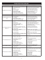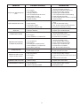
1
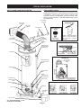
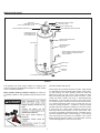
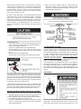
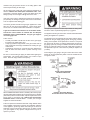
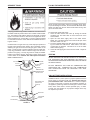
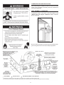
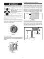
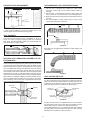
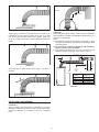
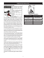
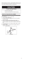
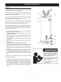
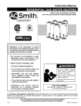
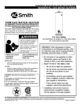
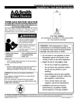
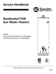
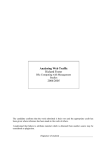
Instruction Manual
RESIDENTIAL GAS WATER HEATERS
DIRECT VENT GAS MODELS GDV/GDVT
NOT FOR USE IN MANUFACTURED (MOBILE) HOMES
A DIVISION OF A. O. SMITH CORPORATION
Ashland City, TN 37015
www.hotwater.com
GAMA certification applies to
all residential gas water heaters with capacities of 20 to
100 gallons with input rating
of 75,000 BTU/Hr. or less.
• For Your Safety •
AN ODORANT IS ADDED TO THE GAS USED
BY THIS WATER HEATER.
ALL TECHNICAL AND WARRANTY QUESTIONS: SHOULD BE DIRECTED TO THE LOCAL DEALER FROM WHOM THE WATER
HEATER WAS PURCHASED. IF YOU ARE UNSUCCESSFUL, PLEASE WRITE TO THE COMPANY LISTED ON THE RATING
PLATE ON THE WATER HEATER.
KEEP THIS MANUAL IN THE POCKET ON HEATER FOR FUTURE REFERENCE
WHENEVER MAINTENANCE ADJUSTMENT OR SERVICE IS REQUIRED.
PRINTED IN CANADA 0608
PART NO. 186589-004 REV. B
SAFE INSTALLATION, USE AND SERVICE
Your safety and the safety of others is extremely important in the installation, use and servicing of this water heater.
Many safety-related messages and instructions have been provided in this manual and on your own water heater to warn
you and others of a potential injury hazard. Read and obey all safety messages and instructions throughout this manual. It
is very important that the meaning of each safety message is understood by you and others who install, use or service this
water heater.
All safety messages will generally tell you about the type of hazard, what can happen if you do not follow the safety message
and how to avoid the risk of injury.
IMPORTANT DEFINITIONS
• Qualified Installer: A qualified installer must have ability equivalent to a licensed tradesman in the fields of plumbing,
air supply, venting and gas supply, including a thorough understanding of the requirements of the “Natural Gas and
Propane Installation Code” CAN/CSA-B149.1 as it relates to the installation of gas fired water heaters. The qualified
installer must also be familiar with the design features and use of flammable vapor ignition resistant water heaters, and
have a thorough understanding of this instruction manual.
• Service Agency: A service agency also must have ability equivalent to a licensed tradesman in the fields of plumbing,
air supply, venting and gas supply, including a thorough understanding of the requirements of the “Natural Gas and
Propane Installation Code” CAN/CSA-B149.1 as it relates to the installation of gas fired water heaters. The service
agency must also have a thorough understanding of this instruction manual, and be able to perform repairs strictly in
accordance with the service guidelines provided by the manufacturer.
• Gas Supplier: The Natural Gas or Propane Utility or service who supplies gas for utilization by the gas burning
appliances within this application. The gas supplier typically has responsibility for the inspection and code approval of
gas piping up to and including the Natural Gas meter or Propane storage tank of a building. Many gas suppliers also
offer service and inspection of appliances within the building.
2
GENERAL SAFETY
3
TABLE OF CONTENTS
SAFE INSTALLATION, USE AND SERVICE . . . . . . . . . . . . . 2
GENERAL SAFETY . . . . . . . . . . . . . . . . . . . . . . . . . . . . . . . . 3
TABLE OF CONTENTS . . . . . . . . . . . . . . . . . . . . . . . . . . . . . 4
INTRODUCTION . . . . . . . . . . . . . . . . . . . . . . . . . . . . . . . . . . . 4
Preparing for the installation . . . . . . . . . . . . . . . . . . . . . . . 4
TYPICAL INSTALLATION . . . . . . . . . . . . . . . . . . . . . . . . . . . 5-6
Get to know your water heater . . . . . . . . . . . . . . . . . . . . . 5
Replacement parts . . . . . . . . . . . . . . . . . . . . . . . . . . . . . . . 5
Mixing valve useage . . . . . . . . . . . . . . . . . . . . . . . . . . . . . 6
LOCATING THE NEW WATER HEATER . . . . . . . . . . . . . . . 7-8
Facts to consider about location . . . . . . . . . . . . . . . . . . . . 7
Insulation blankets . . . . . . . . . . . . . . . . . . . . . . . . . . . . . . . 8
Ventilation for appliances located in confined spaces . . . . 8
Vent termination . . . . . . . . . . . . . . . . . . . . . . . . . . . . . . . . . 8
INSTALLING THE NEW WATER HEATER . . . . . . . . . . . . . 9-17
Required ability . . . . . . . . . . . . . . . . . . . . . . . . . . . . . . . . . 9
Inspect shipment . . . . . . . . . . . . . . . . . . . . . . . . . . . . . . . . 9
General . . . . . . . . . . . . . . . . . . . . . . . . . . . . . . . . . . . . . . . 9
Water piping . . . . . . . . . . . . . . . . . . . . . . . . . . . . . . . . . . . . 9
T & P valve and pipe insulation (if supplied) . . . . . . . . . . 10
Temperature-pressure relief valve . . . . . . . . . . . . . . . . . . 10
Water (potable) heating and space heating . . . . . . . . . . . .11
Closed water system . . . . . . . . . . . . . . . . . . . . . . . . . . . . .11
Gas piping . . . . . . . . . . . . . . . . . . . . . . . . . . . . . . . . . . . . .11
Sediment traps . . . . . . . . . . . . . . . . . . . . . . . . . . . . . . . . . 13
Filling the water heater . . . . . . . . . . . . . . . . . . . . . . . . . . 13
Venting . . . . . . . . . . . . . . . . . . . . . . . . . . . . . . . . . . . . . . . 13
High altitude installations . . . . . . . . . . . . . . . . . . . . . . . . . 13
Combustion air and ventilation . . . . . . . . . . . . . . . . . . . . 14
Vent terminal clearances . . . . . . . . . . . . . . . . . . . . . . . . . 14
Vent connections . . . . . . . . . . . . . . . . . . . . . . . . . . . . . . . 15
Locating clearance hole for vent . . . . . . . . . . . . . . . . . . . 15
High rise vent arrangement . . . . . . . . . . . . . . . . . . . . . . . 15
Standard vent arrangement . . . . . . . . . . . . . . . . . . . . . . . 16
Vent assembly . . . . . . . . . . . . . . . . . . . . . . . . . . . . . . . . . 16
Securing vent termination assembly to the exterior wall . 16
Uncompressing the corrugated tubing . . . . . . . . . . . . . . . 16
Vent restricter plate . . . . . . . . . . . . . . . . . . . . . . . . . . . . . 16
Offset vent arrangement Condition 1 . . . . . . . . . . . . . . . . 17
Offset vent arrangement Condition 2 . . . . . . . . . . . . . . . . 17
LIGHTING & OPERATING LABEL . . . . . . . . . . . . . . . . . . . . 18
TEMPERATURE REGULATION . . . . . . . . . . . . . . . . . . . . . . 19
Temperature regulation . . . . . . . . . . . . . . . . . . . . . . . . . . 19
FOR YOUR INFORMATION . . . . . . . . . . . . . . . . . . . . . . . 20-21
External damage . . . . . . . . . . . . . . . . . . . . . . . . . . . . . . . 20
Start up conditions . . . . . . . . . . . . . . . . . . . . . . . . . . . . . . 20
Condensate . . . . . . . . . . . . . . . . . . . . . . . . . . . . . . . . . . . 20
Smoke/odor . . . . . . . . . . . . . . . . . . . . . . . . . . . . . . . . . . . 20
Thermal expansion . . . . . . . . . . . . . . . . . . . . . . . . . . . . . 20
Strange sounds . . . . . . . . . . . . . . . . . . . . . . . . . . . . . . . . 20
Operational Conditions . . . . . . . . . . . . . . . . . . . . . . . . . . 20
Smelly water . . . . . . . . . . . . . . . . . . . . . . . . . . . . . . . . . . 20
“Air” in hot water systems . . . . . . . . . . . . . . . . . . . . . . . . 21
High water temperature shut off system . . . . . . . . . . . . . 21
MAINTENANCE . . . . . . . . . . . . . . . . . . . . . . . . . . . . . . . . 22-24
Venting system inspection . . . . . . . . . . . . . . . . . . . . . . . . 22
Pilot and main burner. . . . . . . . . . . . . . . . . . . . . . . . . . . . 22
Temperature & Pressure relief valve . . . . . . . . . . . . . . . . 23
Draining . . . . . . . . . . . . . . . . . . . . . . . . . . . . . . . . . . . . . . 23
Cathodic protection - anode. . . . . . . . . . . . . . . . . . . . . . . 23
Anode rod maintenance . . . . . . . . . . . . . . . . . . . . . . . . . . 23
Drain valve washer replacement . . . . . . . . . . . . . . . . . . . 24
LEAKAGE CHECKPOINTS. . . . . . . . . . . . . . . . . . . . . . . . . . 25
Service . . . . . . . . . . . . . . . . . . . . . . . . . . . . . . . . . . . . . . . 25
TROUBLESHOOTING GUIDELINES . . . . . . . . . . . . . . . . 26-27
NOTES . . . . . . . . . . . . . . . . . . . . . . . . . . . . . . . . . . . . . . . . . 28
WARRANTY . . . . . . . . . . . . . . . . . . . . . . . . . . . . . . . . . . . 29-30
INTRODUCTION
Thank You for purchasing this water heater. Properly installed
and maintained, it should give you years of trouble free service.
2.
Abbreviations Found In This Instruction Manual:
• CSA
- Canadian Standards Association
• ANSI
- American National Standards Institute
• NFPA
- National Fire Protection Association
• ASME
- American Society of Mechanical Engineers
• GAMA
- Gas Appliance Manufacturer’s Association
• UL
- Underwriters Laboratories Inc.
3.
This gas-fired water heater is design certified by Underwriters
Laboratories Inc. under American National Standard/CSA Standard for Gas Water Heaters ANSI Z21.10.1 • CSA 4.1 (current
edition).
4.
PREPARING FOR THE INSTALLATION
1. Read the “General Safety” section, page 3 of this manual
first and then the entire manual carefully. If you don’t follow
the safety rules, the water heater will not operate properly. It
could cause DEATH, SERIOUS BODILY INJURY AND/OR
PROPERTY DAMAGE. This manual contains instructions for
the installation, operation, and maintenance of the gas-fired
water heater. It also contains warnings throughout the manual that you must read and be aware of. All warnings and all
instructions are essential to the proper operation of the water
heater and your safety. Since we cannot put everything on
the first few pages, READ THE ENTIRE MANUAL BEFORE
5.
4
ATTEMPTING TO INSTALL OR OPERATE THE WATER
HEATER.
The installation must conform with these instructions and the
local code authority having jurisdiction. In the absence of local codes, installations shall comply with the “Natural Gas
and Propane Installation Code” CAN/CSA-B149.1. This
publication is available from the Canadian Standards Association, 5060 Spectrum Way, Mississauga, Ontario, Canada,
L4W 5N6.
If after reading this manual you have any questions or do not
understand any portion of the instructions, call the local gas
utility or the manufacturer whose name appears on the rating
plate.
Carefully plan the place where you are going to put the water
heater. Correct combustion, vent action, and vent pipe installation are very important in preventing death from possible
carbon monoxide poisoning and fires, see Figures 1 and 2.
Examine the location to ensure the water heater complies
with the “Locating the New Water Heater” section in this
manual.
In Earthquake Zones the water heater must be braced, anchored, or strapped to avoid moving during an earthquake.
Contact local utilities for code requirements in your area.
TYPICAL INSTALLATION
GET TO KNOW YOUR WATER HEATER
REPLACEMENT PARTS
Replacement parts may be ordered through authorized servicers
or distributors. When ordering parts, provide complete model
and serial numbers (see rating plate), quantity and name of part
desired (as listed in Figure 1). Standard hardware items may be
purchased locally.
COLD WATER
INLET PIPE
TRIM PLATE
(OUTSIDE)
TRIM PLATE
(INSIDE)
INLET VALVE
THERMAL
EXPANSION TANK
VACUUM RELIEF
VALVE
UNION
HOT WATER
OUTLET PIPE
ANODE
THERMAL
EXPANSION
TANK
INLET DIP
TUBE
INSTALL PER
LOCAL CODES.
INSTALL THERMAL EXPANSION
TANK IF WATER HEATER IS
INSTALLED IN A CLOSED
SYSTEM.
GAS PILOT & MAIN BURNER
TEMPERATURE
AND PRESSURE
RELIEF VALVE
PILOT
FLUE BAFFLE
THERMOCOUPLE
PIEZO ELECTRODE
THERMOSTAT
DISCHARGE PIPE
(DO NOT CAP OR
PLUG)
GAS SUPPLY
LINE
GAS CONTROL
KNOB
WATER
TEMPERATURE
ADJUSTING DIAL
MAIN MANUAL
GAS SHUTOFF
VALVE
DRAIN VALVE
GROUND-JOINT
UNION
DIRT LEG
GAS CONTROL
DRAINPAN
6” MAXIMUM
AIR GAP
FLOOR DRAIN
OUTER DOOR
ALL PIPING MATERIALS TO BE
SUPPLIED BY CUSTOMER.
FIGURE 1
5
MIXING VALVE USAGE
NON-SCALD
TEMPERING VALVE
(*ALSO CALLED MIXING VALVE)
TEMPERED POTABLE WATER
SHUT-OFF VALVE
COLD WATER INLET
NON-TEMPERED WATER SUPPLY
NON-TEMPERED WATER RETURN
SUGGESTED PIPING
ARRANGEMENT FOR
TOP CONNECTIONS
TEMPERATURE-PRESSURE
RELIEF VALVE
GAS SUPPLY
DISCHARGE PIPE
(DO NOT CAP
OR PLUG)
CERTAIN MODELS ARE EQUIPPED WITH
SIDE PLUMBING CONNECTIONS FOR
SPACE HEATING.
DRAIN VALVE
DRAIN PAN
6” MAXIMUM
AIR GAP
TO SUITABLE DRAIN
FIGURE 2
This appliance has been design certified as complying with
American National Standard/CSA Standard for water heaters
and is considered suitable for:
HOTTER WATER CAN SCALD:
Water heaters are intended to produce hot water. Water heated
to a temperature which will satisfy space heating, clothes washing, dish washing, and other sanitizing needs can scald and
permanently injure you upon contact. Some people are more
likely to be permanently injured by hot water than others. These
include the elderly, children, the infirm, or physically/mentally
handicapped. If anyone using hot water in your home fits into
one of these groups or if there is a local code or state law requiring a certain temperature water at the hot water tap, then you
must take special precautions. In addition to using the lowest
possible temperature setting that satisfies your hot water needs,
a means such as a *mixing valve, should be used at the hot
water taps used by these people or at the water heater. Mixing valves are available at plumbing supply or hardware stores.
Consult a Qualified Installer or Service Agency. Follow mixing
valve manufacturer’s instructions for installation of the valves.
Before changing the factory setting on the thermostat, read the
“Temperature Regulation” section in this manual.
Water (Potable) Heating and Space Heating: All models are
considered suitable for water (potable) heating and space heating.
6
LOCATING THE NEW WATER HEATER
FACTS TO CONSIDER ABOUT THE LOCATION
•
Carefully choose an indoor location for the new water heater,
because the placement is a very important consideration for the
safety of the occupants in the building and for the most economical use of the appliance. This water heater is not for use in
manufactured (mobile) homes or outdoor installation.
Sensors mounted in the drain pan that trigger an alarm or
turn off the incoming water to the water heater when leakage
is detected.
•
Sensors mounted in the drain pan that turn off the water supply to the entire home when water is detected in the drain
pan.
•
Water supply shut-off devices that activate based on the water pressure differential between the cold water and hot water
pipes connected to the water heater.
•
Devices that will turn off the gas supply to a gas water heater
while at the same time shutting off its water supply.
Also, the water heater must be located and/or protected so it is
not subject to physical damage by a moving vehicle.
Whether replacing an old water heater or putting the water heater
in a new location, the following critical points must be observed:
1. Select a location indoors as close as practical to the vent
terminal or location to which the water heater vent piping is
going to be connected, and as centralized with the water piping system as possible.
2. Selected location must provide adequate clearances for servicing and proper operation of the water heater.
This water heater must not be installed directly on carpeting.
Carpeting must be protected by metal or wood panel beneath
the appliance extending beyond the full width and depth of the
appliance by at least 76mm (3 in.) in any direction, or if the appliance is installed in an alcove or closet, the entire floor must be
covered by the panel. Failure to heed this warning may result
in a fire hazard.
Installation of the water heater must be accomplished in such a
manner that if the tank or any connections should leak, the flow
will not cause damage to the structure or any property. For this
reason, it is not advisable to install the water heater in an attic
or upper floor. When such locations cannot be avoided, a suitable drain pan should be installed under the water heater. Drain
pans are available at your local hardware store. Such a drain
pan must have a minimum length and width of at least 51mm (2
in.) greater that the water heater dimensions and must be piped
to an adequate drain. The pan must not restrict combustion air
flow.
Water heater life depends upon water quality, water pressure
and the environment in which the water heater is installed. Water heaters are sometimes installed in locations where leakage
may result in property damage, even with the use of a drain
pan piped to a drain. The manufacturer assumes no liability for
damages resulting from leaks. However, unanticipated damage
can be reduced or prevented by a leak detector or water shutoff device used in conjunction with a piped drain pan. These
devices, strongly recommended for installations where damage
from a leak is possible, are available from some plumbing supply wholesalers and retailers, and detect and react to leakage in
various ways:
7
VENT TERMINATION
Before installing water heater determine placement of vent termination.
Make certain to observe vent location limitation, see Figures 3,
4 & 12.
Minimum
clearances
between
the
water
heater
and combustible and noncombustible construction are: 0mm (0
in.) from sides, 0mm (0 in.) from back, 102mm (4 in.) from front
of jacket to closet door and 508mm (20 in.) from top of jacket
to combustible and noncombustible material. Minimum vent
clearance: 25mm (1 in.)*. Provide 915mm (3 ft.) front clearance
for servicing and adequate clearance between the jacket top &
ceiling for servicing the flue area, see Figure 4.
INSULATION BLANKETS
Insulation blankets available to the general public for external use
on gas water heaters are not necessary with this product. The
purpose of an insulation blanket is to reduce the standby heat
loss encountered with storage tank water heaters. Your Water
heater meets or exceeds the National Appliance Energy Conservation Act standards with respect to insulation and standby loss
requirements, making an insulation blanket unnecessary.
* Where the wall is combustible and the wall thickness is over
356mm (14 in.), 25mm (1 in.) clearance to combustible materials
around the vent terminal is needed. The first 356mm (14 in.) is
zero clearance.
Should you choose to apply an insulation blanket to this heater,
you should follow these instructions (See Figure 1 for identification of components mentioned below). Failure to follow these
instructions can restrict the air flow required for proper combustion, resulting in fire, asphyxiation, serious personal injury or
death.
Make certain the vent locations comply with the “Natural Gas
and Propane Installation Code” CAN/CSA-B149.1 and/or local codes. There is some important information shown in Figure
12.
For a second or more direct vent unit, the distance between vent
terminals must be a minimum of 305mm (12 in.).
•
•
Do not cover the outer door, thermostat or temperature &
pressure relief valve.
Do not cover the instruction manual. Keep it on the side of
the water heater or nearby for future reference.
VENTILATION FOR APPLIANCES LOCATED IN
CONFINED SPACES
FIGURE 4
FIGURE 3
Confined Space is a space whose volume is less than 50 cubic
feet per 1,000 Btu per hour (4.8 cm per kW) of the aggregate
input rating of all appliances installed in that space.
8
INSTALLING THE NEW WATER HEATER
REQUIRED ABILITY
INSTALLATION OR SERVICE OF THIS WATER HEATER
REQUIRES ABILITY EQUIVALENT TO THAT OF A LICENSED
TRADESMAN IN THE FIELD INVOLVED. PLUMBING, AIR
SUPPLY, VENTING AND GAS SUPPLY ARE REQUIRED.
INSPECT SHIPMENT
This water heater shall not be connected to any heating systems
or component(s) used with a non-potable water heating appliance.
There may be hidden damage caused in transit. Check to
be certain all parts of the venting system, as listed below,
are present. CAUTION!!! IF THERE ARE ANY DAMAGED
PARTS, DO NOT INSTALL THIS WATER HEATER. REPORT
ANY SHORTAGE TO YOUR DISTRIBUTOR OR DAMAGE TO
YOUR CARRIER.
All piping components connected to this unit for space heating
applications shall be suitable for use with potable water.
Toxic chemicals, such as those used for boiler treatment shall
not be introduced into this system.
GENERAL
The installation must conform to these instructions and the local
code authority having jurisdiction. In the absence of local codes,
the installation must comply with the current editions of the “Natural Gas and Propane Installation Code” CAN/CSA-B149.1.
The code is available from the Canadian Standards Association,
5060 Spectrum Way, Mississauga, Ontario, Canada, L4W 5N6.
When the system requires water for space heating at temperatures higher than required for domestic water purposes, a
*mixing valve must be installed. Please refer to Figure 2 for
suggested piping arrangement.
Water supply systems may, because of such events as high line
pressure, frequent cut-offs, the effects of water hammer among
others, have installed devices such as pressure reducing valves,
check valves, back flow preventers, etc. to control these types of
problems. When these devices are not equipped with an internal
by-pass, and no other measures are taken, the devices cause
the water system to be closed. As water is heated, it expands
(thermal expansion) and closed systems do not allow for the
expansion of heated water.
WATER PIPING
The water within the water heater tank expands as it is heated
and increases the pressure of the water system. If the relieving
point of the water heater’s temperature-pressure relief valve
is reached, the valve will relieve the excess pressure. The
temperature-pressure relief valve is not intended for the
constant relief of thermal expansion. This is an unacceptable
condition and must be corrected.
It is recommended that any devices installed which could create
a closed system have a by-pass and/or the system have an expansion tank to relieve the pressure built by thermal expansion
in the water system. Expansion tanks are available for ordering
through a local plumbing contractor. Contact the local water
supplier and/or a service agency for assistance in controlling
these situations.
HOTTER WATER CAN SCALD:
Water heaters are intended to produce hot water. Water heated
to a temperature which will satisfy space heating, clothes washing, dish washing, cleaning and other sanitizing needs can scald
and permanently injure you upon contact. Some people are
more likely to be permanently injured by hot water than others.
These include the elderly, children, the infirm, or physically/mentally handicapped. If anyone using hot water in your home fits
into one of these groups or if there is a local code or state law
requiring a certain temperature water at the hot water tap, then
you must take special precautions. In addition to using the lowest possible temperature setting that satisfies your hot water
needs, a means such as a *mixing valve, should be used at the
hot water taps used by these people or at the water heater, see
Figure 2. Valves for reducing point of use temperature by mixing
cold and hot water are also available:
NOTE: To protect against untimely corrosion of hot and cold
water fittings, it is strongly recommended that di-electric
unions or couplings be installed on this water heater when
connected to copper pipe.
All gas piping must comply with local codes and ordinances or
with the “Natural Gas and Propane Installation Code” CAN/
CSA-B149.1 whichever applies. Copper and brass tubing and
fittings (except tin lined copper tubing) shall not be used.
Consult a Qualified Installer or Service Agency. Follow manufacturer’s instructions for installation of the valves. Before
changing the factory setting on the thermostat, read the “Temperature Regulation” section in this manual.
9
FIGURE 6
HOT WATER
OUTLET
COLD WATER
INTLET
Fit pipe insulation over the incoming cold water line and the hot
water line. Make sure that the insulation is against the top cover
of the heater.
Fit T & P valve insulation over valve. Make sure that the insulation does not interfere with the lever of the T & P valve.
SHUTOFF
VALVE
UNION
3/4” SWEAT
FITTING
UNION
3/4” SWEAT
FITTING
Secure all insulation using tape.
TEMPERATURE
AND PRESSURE
RELIEF VALVE
TEMPERATURE-PRESSURE RELIEF VALVE
DISCHARGE PIPE
(DO NOT CAP
OR PLUG)
DRAIN PAN
DRAIN VALVE
6” MAXIMUM
AIR GAP
FLOOR DRAIN
FIGURE 5
Figure 5 shows the typical attachment of the water piping to the
water heater. The water heater is equipped with 3/4“ NPT water
connections.
This heater is provided with a properly certified combination
temperature - pressure relief valve by the manufacturer.
NOTE: If using copper tubing, solder tubing to an adapter before
attaching the adapter to the cold water inlet connection. Do not
solder the cold water supply line directly to the cold water inlet.
It will harm the dip tube and damage the tank.
The valve is certified by a nationally recognized testing laboratory that maintains periodic inspection of production of listed
equipment of materials as meeting the requirements for Relief
Valves for Hot Water Supply Systems, ANSI Z21.22 • CSA 4.4,
and the code requirements of ASME.
T & P VALVE AND PIPE INSULATION (IF SUPPLIED)
If replaced, the valve must meet the requirements of local codes,
but not less than a combination temperature and pressure relief
valve certified as indicated in the above paragraph.
The valve must be marked with a maximum set pressure not to exceed the marked hydrostatic working pressure of the water heater
(150 psi = 1,035 kPa) and a discharge capacity not less than the
water heater input rate as shown on the model rating plate.
Remove insulation for T & P valve and pipe connections from
carton.
For safe operation of the water heater, the relief valve must not
be removed from its designated opening nor plugged.
The temperature-pressure relief valve must be installed directly
into the fitting of the water heater designed for the relief valve.
Position the valve downward and provide tubing so that any
discharge will exit only within 152mm (6 in.) above, or at any
10
distance below the structural floor. Be certain that no contact is
made with any live electrical part. The discharge opening must
not be blocked or reduced in size under any circumstances.
Excessive length, over 30 ft. (9.14m), or use of more than four
elbows can cause restriction and reduce the discharge capacity
of the valve, see Figures 5 or 10.
4. When the system requires water for space heating at
temperatures higher than required for domestic water
purposes, a *mixing valve must be installed, see Figure 7 for
suggested piping arrangement.
No valve or other obstruction is to be placed between the relief
valve and the tank. Do not connect tubing directly to discharge
drain unless a 152mm (6 in.) air gap is provided. To prevent
bodily injury, hazard to life, or property damage, the relief valve
must be allowed to discharge water in quantities should circumstances demand. If the discharge pipe is not connected to a
drain or other suitable means, the water flow may cause property
damage.
The Discharge Pipe:
• Shall not be smaller in size than the outlet pipe size of the
valve, or have any reducing couplings or other restrictions.
• Shall not be plugged or blocked.
• Shall be of material listed for hot water distribution.
• Shall be installed so as to allow complete drainage of both
the temperature-pressure relief valve, and the discharge
pipe.
• Shall terminate at an adequate drain.
• Shall not have any valve between the relief valve and tank.
FIGURE 7
CLOSED WATER SYSTEM
A closed system will exist if a back-flow preventer (check valve),
pressure reducing valve, or other similar device is installed in
the cold water line between the water heater and the street main
(or well). Excessive pressure may develop due to the thermal
expansion of heated water causing premature tank failure or
intermittent relief valve operation. This type of failure is not
covered by the limited warranty. An expansion tank may be
necessary in the cold water supply to alleviate this situation, see
Figure 1. Contact the local plumbing authority.
If the temperature and pressure relief valve on the appliance
discharges periodically, this may be due to thermal expansion
in a closed water supply system. Contact the water supplier or
local plumbing inspector on how to correct this situation. DO
NOT PLUG THE TEMPERATURE AND PRESSURE RELIEF
VALVE.
GAS PIPING
The temperature-pressure relief valve must be manually operated at least once a year. Caution should be taken to ensure that
(1) no one is in front of or around the outlet of the temperaturepressure relief valve discharge line, and (2) the water manually
discharged will not cause any bodily injury or property damage
because the water may be extremely hot.
If after manually operating the valve, it fails to completely reset
and continues to release water, immediately close the cold water
inlet to the water heater, follow the draining instructions, and replace the temperature-pressure relief valve with a new one.
WATER (POTABLE) HEATING AND SPACE HEATING
1. All piping components connected to this unit for space heating
applications shall be suitable for use with potable water.
2. Toxic chemicals, such as those used for boiler treatment,
shall NEVER be introduced into this system.
3. This unit may NEVER be connected to any existing heating
system or component(s) previously used with a non-potable
water heating appliance.
Make sure the gas supplied is the same type listed on the model
rating plate. The inlet gas pressure must not exceed 14 inch
water column (3.5 kPa) for natural and propane gas (L.P.). The
11
minimum inlet gas pressure shown on the rating plate is that
which will permit firing at rated input.
All gas piping must comply with local codes and ordinances or
with the “Natural Gas and Propane Installation Code” CAN/
CSA-B149.1 whichever applies. Copper and brass tubing and
fittings (except tin lined copper tubing) shall not be used.
If the gas control valve is subjected to pressures exceeding 1/2
psi (3.5 kPa), the damage to the gas control valve could result in
a fire or explosion from leaking gas.
If the main gas line Shut-off serving all gas appliances is used,
also turn “off” the gas at each appliance. Leave all gas appliances shut “off” until the water heater installation is complete.
Use pipe joint compound or teflon tape marked as being resistant to the action of petroleum [Propane (L.P.)] gases.
A gas line of sufficient size must be run to the water heater.
Consult the current edition of “Natural Gas and Propane
Installation Code” CAN/CSA-B149.1 and your gas supplier
concerning pipe size.
The appliance and its gas connection must be leak tested before
placing the appliance in operation.
The appliance and its individual Shut-off valve shall be disconnected from the gas supply piping system during any pressure
testing of that system at test pressures in excess of 1/2 pound
per square inch (3.5 kPa). It shall be isolated from the gas supply piping system by closing its individual manual Shut-off valve
during any pressure testing of the gas supply piping system at
test pressures equal to or less than 1/2 pound per square inch
(3.5 kPa).
There must be:
• A readily accessible manual shut off valve in the gas supply
line serving the water heater, and
• A drip leg (sediment trap) ahead of the gas control valve to
help prevent dirt and foreign materials from entering the gas
control valve.
• A flexible gas connector or a ground joint union between the
shut off valve and control valve to permit servicing of the
unit.
Connecting the gas piping to the gas control valve of the water
heater can be accomplished by either of the two methods shown
in Figures 8 and 9.
Be sure to check all the gas piping for leaks before lighting the
water heater. Use a soapy water solution, not a match or open
flame. Rinse off soapy solution and wipe dry.
FIGURE 8 GAS PIPING WITH
FLEXIBLE CONNECTOR.
FIGURE 9 GAS PIPING WITH ALL
BLACK IRON PIPE TO GAS CONTROL.
When installed at elevations above 7,700 feet (2,347 meters), input
rating should be reduced at the rate of 4 percent for each 1,000 feet
(305 meters) above sea level which requires replacement of the
burner orifice in accordance with “Natural Gas and Propane
Installation Code” CAN/CSA-B149.1. Contact your local gas
supplier for further information.
Failure to replace the standard orifice with a high altitude orifice
when installed could result in improper and inefficient operation
of the appliance, producing carbon monoxide gas in excess of
safe limits, which could result in serious injury or death. Contact
your gas supplier for any specific changes which may be required in your area.
12
FILLING THE WATER HEATER
SEDIMENT TRAPS
Never use this water heater unless it is completely full of water.
To prevent damage to the tank, the tank must be filled with water.
Water must flow from the hot water faucet before turning “ON”
gas to the water heater.
A drip leg (sediment trap) shall be installed as close to the inlet of
the water heater as practical at the time of water heater installation. The sediment trap shall be either a tee fitting with a capped
nipple in the bottom outlet or other device recognized as an effective sediment trap. If a tee fitting is used, it shall be installed
in conformance with one of the methods of installation shown in
Figures 8 and 9.
To fill the water heater with water:
1. Close the water heater drain valve by turning the handle
clockwise ( ). The drain valve is on the lower front of the
water heater.
2. Open the cold water supply valve to the water heater.
NOTE: The cold water supply valve must be left open when
the water heater is in use.
3. To insure complete filling of the tank, allow air to exit by opening the nearest hot water faucet. Allow water to run until a
constant flow is obtained. This will let air out of the water
heater and the piping.
4. Check all water piping and connections for leaks. Repair as
needed.
Contaminants in the gas lines may cause improper operation of
the gas control valve that may result in fire or explosion. Before
attaching the gas line be sure that all gas pipe is clean on the
inside. To trap any dirt or foreign material in the gas supply line,
a drip leg (sometimes called a sediment trap) must be incorporated in the piping. The drip leg must be readily accessible.
Install in accordance with the “Gas Piping” section. Refer to the
current edition of the “Natural Gas and Propane Installation
Code” CAN/CSA-B149.1
HOT WATER
OUTLET
VENTING
NEVER OPERATE THE HEATER UNLESS IT IS VENTED TO
THE OUTDOORS AND HAS ADEQUATE AIR SUPPLY TO
AVOID RISKS OF IMPROPER OPERATION, FIRE, EXPLOSION
OR ASPHYXIATION.
COLD WATER
INTLET
SHUTOFF
VALVE
UNION
DO NOT OBSTRUCT THE FLOW OF COMBUSTION AND
VENTILATING AIR. ADEQUATE AIR FOR COMBUSTION
AND VENTILATION MUST BE PROVIDED FOR SAFE
OPERATION.
UNION
TEMPERATURE
AND PRESSURE
RELIEF VALVE
HIGH ALTITUDE INSTALLATIONS
Installations above 7,700 ft. (2347 m) require replacement of the
burner orifice in accordance with the “Natural Gas and Propane Installation Code” CAN/CSA-B149.1. Failure to replace
the orifice could result in improper and inefficient operation of
the appliance, producing carbon monoxide gas in excess of safe
limits, which could result in serious personal injury or death.
Contact your gas supplier for any specific changes which may
be required in your area.
DISCHARGE PIPE
(DO NOT CAP
OR PLUG)
DRAIN PAN
DRAIN VALVE
6” MAXIMUM
AIR GAP
FLOOR DRAIN
FIGURE 10
13
COMBUSTION AIR AND VENTILATION
When determining the installation location for a direct vent water
heater, snow accumulation and drifting should be considered in
areas where applicable.
VENT TERMINAL CLEARANCES
The vent system must terminate so that proper clearances are
maintained as cited in local codes or the current edition of the
“Natural Gas and Propane Installation Code” CAN/CSAB149.1 as follows:
FIGURE 11
Be sure venting is properly connected to prevent escape of dangerous flue gases which could cause deadly asphyxiation.
*Minimum 9 in. (23 cm) for appliances with
10,000 btuh (3 Kw) to 50,000 btuh
(15 Kw) inputs and 12 in. (30 cm)
for appliances greater than
50,000 btuh (15 Kw) to
a window or door
that may be opened
12 in. (30 cm)
from soffit
Minimum
7 ft. (2.3 m)
above
public sidewalk
or paved
driveway
*
Minimum 18 in. (46 cm)
12 in. (30 cm)
above grade or
anticipated snow
level
Minimum 3 ft. (91 cm) within a
height of 15 ft. (4.6 cm) above
meter/regulator assembly
Minimum 3 ft. (91 cm) clearance
to service regulator vent outlet
Minimum
2 ft. (61 cm)
from outside
corner
Minimum 12 in. (30 cm)
under veranda, porch,
deck or balcony
(see footnote 1)
*
*
(see footnote 2)
*
*
Minimum
12 in. (30 cm)
from sides, above or
below a permanently
closed window or door
VENT TERMINAL
AIR SUPPLY INLET
Minimum
3 ft. (91 cm)
above if within
10 ft. (3 m)
horizontally to
a mechanical air
supply inlet
Minimum 9 in. (23 cm) for appliances with 10,000 btuh (3 Kw)
to 50,000 btuh (15 Kw) inputs and 12 in. (30 cm) for appliances greater
than 50,000 btuh (15 Kw) to a non mechanical air supply inlet
into building or combustion air inlet to another appliance
AREA WHERE TERMINAL IS NOT PERMITTED
1. Permitted only if veranda, porch, deck or balcony is fully opened on a minimum of two sides beneath the floor.
2. A vent shall not terminate above a sidewalk or paved driveway that is located between two single family dwellings and serves both dwellings.
FIGURE 12
14
LOCATING CLEARANCE HOLE FOR VENT
Cut a clearance hole, approximately 178mm (7 in.) in diameter,
through the exterior wall for the vent assembly. The recommended
distance, measured from the hole center to bottom of water
heater, is 1.72m (68 in.) for 40 gal. models and 1.93m (76 in.)
for 50 gal., 50 gal. Hi-Input and 75 gal. models. The maximum
distance recommended is 2.03m (80 in.) or in compliance with
Figure 16.
Where the wall is combustible and the wall thickness is over
356mm (14 in.), 25mm (1 in.) clearance to combustible materials
around the vent terminal is needed. The first 356mm (14 in.) is
zero clearance.
7 in. (178mm )
DIAMETER
(SEE TEXT)
BOTTOM OF HEATER
DV TERMINATION SAFETY COVER
FIGURE 15
A Safey cover (see Figure 13) is available to prevent accidental
contact with the vent terminal. Contact your Customer Service
Department for ordering information.
HIGH RISE VENT ARRANGEMENT
When the height H (From vent terminal center line to bottom of
heater) is over 80 in. (2.03m), it is a high rise vent arrangement.
In this case the minimum distance “D” from the center of the
water heater to the outside wall surface is 560mm (22 in.), and
the maximum height of “H” is 3.66m (12 ft.).
D
10 in.
(254mm)
(REF)
WALL THICKNESS
H
FIGURE 13
VENT CONNECTIONS
After the location for the vent terminal has been selected as
outlined in Figures 3, 4 & 12, use the following illustrations for
installation:
TO BOTTOM
OF HEATER
FIGURE 16
FIGURE 14
15
UNCOMPRESSING THE CORRUGATED TUBING
STANDARD VENT ARRANGEMENT
3.6 in.
(91mm)
2.6 in.
(67mm)
17 in. (432mm) MIN.,*
80 in. (2.03m) MAX.
1. Pull the inner corrugated tube towards the water heater
and leave some length over the water heater’s center for
bending.
2. Pull the outer corrugated tube toward the water heater and
leave it 25mm (1 in.) shorter than the inner corrugated tube.
3. Make sure there are two springs evenly spaced at the bend in
the tube.
4. Use metal hangers to keep venting level or with a slope
upward from the heater to terminal.
WALL
2.1 in.
(54.5mm)
SPRING
FIGURE 17
* If the horizontal distance is less than 760mm (30 in.), the
restricter plate must be installed (see Figure 22).
VENT ASSEMBLY
REDUCER
H
The vent tube and terminal can be assembled as shown in
Figure 18. There are springs fastened inside the corrugated
tube. When the vent tubes are pulled to a required length, the
springs will still be equally spaced.
SPRING
FIGURE 20
CLAMP
Bend both the corrugated tubes toward the water heater’s flue
connection.
FIGURE 18
SECURING VENT TERMINATION ASSEMBLY TO THE
EXTERIOR WALL.
Some models are supplied with trim plates which may be used to
cover the holes in the wall (see Figures 1 and 19). Slide one trim
plate (if supplied) over the outer corrugated tube, then insert the
outer corrugated tube through the clearance hole from exterior
wall. Secure the trim plate to the exterior wall, then secure the
vent terminal to the exterior wall with 4 screw anchors (included)
appropriate for the type of wall construction. Caulk the junction
of the vent terminal base plate and the exterior wall with exterior
type sealant (not included). Slide the trim plate (inside) over the
outer corrugated tube and fasten the trim plate to the interior
wall. Caulk the junction of the outer corrugated tube and the trim
plate (inside) with suitable sealant.
TRIM PLATE
(INSIDE)
FIGURE 21
VENT RESTRICTER PLATE
For short horizontal vent runs (see Figure 17) place the restricter
plate over the flue tube reducer before connecting the inner corrugated tube to the flue tube reducer. DO NOT use the restricter
plate if the horizontal run is greater than 760mm (30 in.).
SEALANT
UPPER AIR
INLET BOX
RESTRICTER
PLATE
FLUE TUBE
REDUCER
TRIM PLATE
(OUTSIDE)
FIGURE 22
Pull and connect the inner corrugated tube to the water heater’s
flue tube reducer with hi-temp red silicone (included) and gear
clamp. Make sure this connection is tight and leak proof.
*The sealant between inner corrugated tube and water heater’s
flue tube reducer must be hi-temp red silicone or other material
suitable for 315°C (600°F) continuous service.
FIGURE 19
16
TOP VIEW
90° MAXIMUM
BEND
FIGURE 23
FIGURE 26
CONDITION 2:
Apply hi-temp red silicone (included) around the collar on air
manifold box. Pull corrugated vent tube all the way on to collar
and secure with one sheet metal screw (approx. 19mm (3/4
in.) up from edge of vent tube. Pull gear clamp past screw and
tighten.
Where floor joists impede venting, a rise or drop to complete the
vent termination is possible. All installations require 25mm (1 in.)
clearance to combustibles.
Note:
A. The maximum horizontal vent length of 2.03m (80 in.) minus
wall thickness should be considered when installing an offset
vent arrangement.
B. Do not combine condition 1 (Figure 26) with condition 2
(Figure 27) in the same installation.
C. The maximum allowable drop from vent center-line to vent
termination center-line (Figure 27) is 184mm (7.25 in.).
>1 in. (25mm)
>1 in.
(25mm)
FIGURE 24
Check the level or slope of the venting again, and adjust if
required.
“H”
SEE
CHART
7.25 in.
(184mm)
MAX
MODELS
40
50
50
75
SLOPE
gal.
gal.
gal. Hi-INPUT
gal.
FIGURE 27
FIGURE 25
OFFSET VENT ARRANGEMENT
CONDITION 1:
Where a straight vent arrangement is impossible, a horizontal
90 degree maximum bend can be made. Use the water heater
casing outer diameter as a template to form the corrugated
tube.
17
WALL 10 in.
(254mm) (REF)
RECOMMENDED
MINIMUM “H”
68 in. (1.72m)
76 in. (1.93m)
76 in. (1.93m)
76 in. (1.93m)
FOR YOUR SAFETY READ BEFORE OPERATING
WARNING: If you do not follow these instructions exactly, a fire or explosion
may result causing property damage, personal injury or loss of life.
A. This appliance has a pilot that is lit by a piezo-electric spark gas ignition system. Do not open the inner door of the
appliance and try to light the pilot by hand.
B. BEFORE OPERATING smell all around the appliance area for gas. Be sure to smell next to the floor because some
gases are heavier than air and will settle on the floor.
WHAT TO DO IF YOU SMELL GAS
• Do not try to light any appliance.
• Do not touch any electric switch; do not use any phone in your building.
• Immediately call your gas supplier from a neighbour’s phone. Follow the gas supplier’s instructions.
• If you cannot reach your gas supplier, call fire department.
C. Use only your hand to push in or turn the gas control knob. Never use tools. If the knob will not push in or turn by hand,
don't try to repair it, call a qualified service technician. Force or attempted repair may result in a fire or explosion.
D. Do not use this appliance if any part has been under water. Immediately call a qualified service technician to inspect
the appliance and to replace any part of the control system and any gas control which has been under water.
LIGHTING AND OPERATING INSTRUCTIONS
1. STOP! Read the safety information above on this label.
Figure A
2. Set the thermostat to lowest setting.
3. This appliance has a pilot that is lit by a spark gas ignition system. Do not try
PILOT
to light the pilot by hand.
4. Remove the outer burner door.
THERMO5. Push the gas control knob down slightly and turn clockwise
to "OFF" (see
COUPLE
Figure "A").
NOTE: Knob CANNOT be turned from "PILOT" to "OFF" unless it is pushed down
ELECTRODE
slightly. Do not force.
“OFF” Position
6. Wait ten (10) minutes to clear out any gas. Then smell for gas, including near Gas Control Knob
the floor. If you smell gas, STOP! Follow “B” in the safety information above
Top View
on this label. If you don’t smell gas, go to the next step.
Gas Control Knob
7. Make sure the water heater is filled with water.
8. Turn gas control knob counterclockwise
to "PILOT" (see Figure "A").
9. Depress the gas control knob all the way in and IMMEDIATELY depress the
igniter button until you hear a loud click. Observe the pilot through the view
Igniter
port. Do not release the gas control knob. Repeat immediately if pilot does not
Button
light on the first try. If the pilot does not light by the fourth attempt with the
igniter, repeat steps 5-9. Continue to hold the button for about one (1) minute
after the pilot is lit. Release the gas control knob and it will pop back up. Pilot
should remain lit. If the pilot light goes out, repeat steps 5-9.
IMPORTANT: If the pilot will not stay lit after several tries, turn gas control knob
to "OFF" and call your service technician or gas supplier.
IMPORTANT: If the gas control knob does not pop up to its original position when
released, stop and immediately shut off the gas at the line valve or tank. Call your
service technician or gas supplier.
10. Turn gas control knob counter-clockwise
to "ON" (see Figure "A").
11. Once the pilot flame is established replace the outer burner door.
12. Set thermostat to desired setting.
Thermostat Dial
13. If the pilot will not stay lit after several tries, turn the gas control knob clockwise
to "OFF" (see Figure "A"). If the appliance will not operate, follow the
instructions "To Turn Off Gas To Appliance" and call a qualified service techGas Control
nician or gas supplier.
TO TURN OFF GAS TO APPLIANCE
1. Set thermostat to the lowest setting (PILOT LIGHTING).
2. Push the gas control knob down slightly and clockwise
to the “OFF” position. Do not force.
18
71731.1
TEMPERATURE REGULATION
TEMPERATURE REGULATION
HOT WATER CAN SCALD: Water heaters are intended to
produce hot water. Water heated to a temperature that will
satisfy space heating, clothes washing, dish washing, and other
sanitizing needs can scald and permanently injure you upon
contact. Some people are more likely to be permanently injured
by hot water than others. These include the elderly, children, the
infirm, or physically/mentally handicapped. If anyone using hot
water in your home fits into one of these groups or if there is a
provincial, state law or local code requiring a specific hot water
temperature at the tap, then you must take special precautions.
Never allow small children to use a hot water tap, or to draw
their own bath water. Never leave a child or handicapped person
unattended in a bathtub or shower.
Temperature Setting
Time to Produce 2nd & 3rd
Degree Burns on Adult Skin
VERY HOT= approx. 71°C
(160°F)
About 1/2 second
C = approx. 66°C (150°F)
About 1-1/2 seconds
B = approx. 60°C (140°F)
Less than 5 seconds
A = approx. 55°C (130°F)
About 30 seconds
= approx. 49°C (120°F)
LOW = approx. 27°C (80°F)
More than 5 minutes
-----------------------------
FIGURE 28
It is recommended that lower water temperatures be used to
avoid the risk of scalding. It is further recommended, in all cases,
that the water temperature be set for the lowest temperature that
satisfies your hot water needs. This will also provide the most
energy efficient operation of the water heater.
Figure 28 shows the approximate water temperatures produced
at various thermostat dial settings. Short repeated heating
cycles caused by small hot water uses can cause temperatures
at the point of use to exceed the thermostat setting by up to 17°C
(30°F). If you experience this type of use you should consider
using lower temperature settings to reduce scald hazards.
Valves for reducing point-of-use temperature by mixing cold
and hot water are available (see Figures 2 & 7). Also available
are inexpensive devices that attach to faucets to limit hot water
temperatures. Contact a licensed plumber or the local plumbing
authority.
SHOULD OVERHEATING OCCUR OR THE GAS SUPPLY FAIL
TO SHUT OFF, TURN OFF THE MAIN MANUAL GAS CONTROL VALVE TO THE APPLIANCE (SEE FIGURE 1).
NOTE: A water temperature range of 49°C-60°C (120°F-140°F)
is recommended by most dishwasher manufacturers. The thermostat of this water heater has been factory set at its lowest
position (PILOT LIGHTING). It is adjustable and must be reset
to the desired temperature setting to reduce the risk of scald
injury. The mark ( ) indicative of approximately 49°C (120°F)
is preferred starting point. Some provinces may have a requirement for a lower setting.
Turn the water temperature dial clockwise ( ) to decrease the
temperature, or counterclockwise ( ) to increase the temperature.
19
FOR YOUR INFORMATION
EXTERNAL DAMAGE
THERMAL EXPANSION
Do not operate the water heater until it has been fully checked
out by a qualified technician, if the water heater:
•
•
•
Has been exposed to fire or damage.
Displays evidence of sooting.
Produces steam or unusually hot water.
If the water heater has been flooded it must be replaced.
START UP CONDITIONS
Water supply systems may, because of such events as high line
pressure, frequent cut-offs, the effects of water hammer among
others, have installed devices such as pressure reducing valves,
check valves, back flow preventers, etc. to control these types of
problems. When these devices are not equipped with an internal
by-pass, and no other measures are taken, the devices cause
the water system to be closed. As water is heated, it expands
(thermal expansion) and closed systems do not allow for the
expansion of heated water.
NEVER OPERATE THE HEATER WITHOUT FIRST BEING
CERTAIN IT IS FILLED WITH WATER AND A TEMPERATURE
AND PRESSURE RELIEF VALVE IS INSTALLED IN THE RELIEF VALVE OPENING OF THE HEATER. DO NOT ATTEMPT
TO OPERATE HEATER WITH COLD WATER INLET VALVE
CLOSED.
CONDENSATE
Whenever the water heater is filled with cold water, some condensate will form while the burner is on. A water heater may
appear to be leaking when in fact the water is condensate. This
usually happens when:
The water within the water tank expands as it is heated and increases the pressure of the water system. If the relieving point of
the water heater’s temperature-pressure relief valve is reached,
the valve will release the excess pressure. The temperaturepressure relief valve is not intended for the constant relief of
thermal expansion. This is an unacceptable condition and must
be corrected. It is recommended that any devices installed which
could create a closed system have a by-pass and/or the system
have an expansion tank or device to relieve the pressure built
by thermal expansion in the water system. Expansion tanks
are available for ordering through a local plumbing contractor.
Contact the local water heater supplier or service agency for assistance in controlling these situations.
a. A new water heater is filled with cold water for the first time.
b. Burning gas produces water vapor in water heaters, particularly high efficiency models where flue temperatures are
lower.
c. Large amounts of hot water are used in a short time and the
refill water in the tank is very cold.
Moisture from the products of combustion condense on the
cooler tank surfaces and form drops of water which may fall
onto the burner or other hot surfaces to produce a “sizzling” or
“frying” noise.
STRANGE SOUNDS
Possible noises due to expansion and contraction of some metal
parts during periods of heat-up and cool-down do not necessarily
represent harmful or dangerous conditions.
Because of the suddenness and amount of water, condensate
water may be diagnosed as a “tank leak”. After the water in the
tank warms up (about 1-2 hours), the condition should disappear.
Condensation causes sizzling and popping within the burner
area during heating and cooling periods and should be considered normal. See “Condensate” in this section.
Do not assume the water heater is leaking until there has been
enough time for the water in the tank to warm up.
OPERATIONAL CONDITIONS
An undersized water heater will cause more condensation. The
water heater must be sized properly to meet the family’s demands for hot water including dishwashers, washing machines
and shower heads.
SMELLY WATER
In each water heater there is installed at least one anode rod
(see parts section) for corrosion protection of the tank. Certain
water conditions will cause a reaction between this rod and the
water. The most common complaint associated with the anode
rod is one of a “rotten egg smell” in the hot water. The smell is
a result of four factors which must all be present for the odor to
develop:
Excessive condensate may be noticed during the winter and
early spring months when incoming water temperatures are at
their lowest.
Good venting is essential for a gas fired water heater to operate
properly as well as to carry away products of combustion and
water vapor.
a. A concentration of sulfate in the supply water.
b. Little or no dissolved oxygen in the water.
c. A sulfate reducing bacteria which has accumulated within the
water heater (this harmless bacteria is nontoxic to humans).
d. An excess of active hydrogen in the tank. This is caused by
the corrosion protective action of the anode.
SMOKE/ODOR
It is not uncommon to experience a small amount of smoke and
odor during the initial start-up. This is due to burning off of oil
from metal parts, and will disappear in a short while.
Smelly water may be eliminated or reduced in some water heater
models by replacing the anode(s) with one of less active material, and then chlorinating the water heater tank and all water
20
lines. Contact the local water heater supplier or service agency
for further information concerning an Anode Replacement Kit
and this chlorination treatment.
If the smelly water persists after the anode replacement and
chlorination treatment, we can only suggest that chlorination or
aeration of the water supply be considered to eliminate the water
problem.
Do not remove the anode leaving the tank unprotected. By doing
so, all warranty on the water heater tank is voided.
“AIR” IN HOT WATER FAUCETS
HYDROGEN GAS: Hydrogen gas can be produced in a hot
water system that has not been used for a long period of time
(generally two weeks or more). Hydrogen gas is extremely flammable and explosive. To prevent the possibility of injury under
these conditions, we recommend the hot water faucet, located
farthest away, be opened for several minutes before any electrical appliances which are connected to the hot water system are
used (such as a dishwasher or washing machine). If hydrogen
gas is present, there will probably be an unusual sound similar to
air escaping through the pipe as the hot water faucet is opened.
There must be no smoking or open flame near the faucet at the
time it is open.
HIGH WATER TEMPERATURE SHUT OFF SYSTEM
This water heater is equipped with an automatic gas shut-off
system. This system works when high water temperatures are
present. Turn “OFF” the entire gas supply to the water heater.
The high temperature shut-off is built into the gas control valve.
It is non-resettable. If the high temperature shut-off activates, the
gas control valve must be replaced. Contact your gas supplier
or service agency.
21
MAINTENANCE
FOR YOUR SAFETY AND SATISFACTORY OPERATION, IT IS
RECOMMENDED THAT THIS HEATER BE CHECKED ONCE A
YEAR BY A COMPETENT SERVICE PERSON.
a flooded water heater. Do not attempt to repair the unit! It must
be replaced!
At least once a year a visual inspection should be made of the
main burner and the pilot assembly for proper flame characteristics. This can be done by removing the Outer Door and viewing
the main burner operation through the Viewport on the Inner
Door, see Figure 1. The main burner should provide complete
combustion of gas, ignite rapidly, give reasonably quiet operation, and cause no excessive flame lifting from the burner ports.
If the proper flame characteristics are not evident (see Figure 1),
make sure that the flow of combustion and ventilation air is not
blocked in the venting system.
USERS OF THIS APPLIANCE SHOULD BE AWARE THAT
GAS COMPONENTS WEAR OUT OVER A PERIOD OF TIME.
THE GAS CARRYING COMPONENTS OF THIS APPLIANCE
SHOULD BE INSPECTED FOR PROPER OPERATION PERIODICALLY BY A QUALIFIED SERVICE TECHNICIAN.
VENTING SYSTEM INSPECTION
You should also check for sooting. Soot is not normal and will
impair proper combustion. A visual inspection of the main burner
and pilot assembly should also be done at least once a year,
see Figure 1.
Soot build-up indicates a problem that requires correction before further use. Turn “OFF” gas to water heater and leave off
until repairs are made, because failure to correct the cause of
the sooting can result in a fire causing death, serious injury, or
property damage.
If proper flame characteristics are not evident, check for accumulation of lint or other foreign material that restricts or blocks the
air openings in the heater or burner.
At least once a year a visual inspection should be made of the
venting system. You should look for:
1. Obstructions which could cause improper venting. The combustion and ventilation air flow must not be obstructed.
2. Damage or deterioration which could cause improper venting
or leakage of combustion products.
Be sure the vent piping is properly connected to prevent escape
of dangerous flue gasses which could cause deadly asphyxiation.
Obstructions and deteriorated vent systems may present serious
health risk or asphyxiation.
Chemical vapor corrosion of the flue and vent system may occur
if air for combustion contains certain chemical vapors. Spray can
propellants, cleaning solvents, refrigerator and air conditioner
refrigerants, swimming pool chemicals, calcium and sodium
chloride, waxes, bleach and process chemicals are typical compounds which are potentially corrosive.
SOOT BUILD-UP INDICATES A PROBLEM THAT REQUIRES
CORRECTION BEFORE FURTHER USE. CONSULT WITH A
QUALIFIED SERVICE TECHNICIAN.
Should the main burner or burner air openings require cleaning,
turn the gas control knob to “OFF” position and allow the burner
to cool. Remove the burner and clean with a soft brush. Clean
main burner orifice with a suitable soft material.
If after inspection of the vent system you found sooting or deterioration, something is wrong. Call the local gas utility to correct
the problem and clean or replace the flue and venting before
resuming operation of the water heater.
PILOT AND MAIN BURNER
Flood damage to a water heater may not be readily visible or immediately detectable. However, over a period of time a flooded
water heater will create dangerous conditions which can cause
DEATH, SERIOUS BODILY INJURY, OR PROPERTY DAMAGE. Contact a qualified installer or service agency to replace
22
DRAINING
If the heater is to be shut off and exposed to freezing temperatures, it must be drained. Water, if left in the tank and allowed to
freeze, will damage the heater.
• Turn off the gas and cold water inlet valve to the heater, Figure
1.
• Open a nearby hot water faucet and the heater drain valve.
• BE CAREFUL TO GRASP THE DRAIN VALVE HANDLE SO
THAT THE HAND IS NOT EXPOSED TO HOT WATER. IF
DESIRED, A HOSE MAY BE CONNECTED TO THE DRAIN
VALVE TO CARRY THE WATER AWAY.
The water CAN BE HOT.
• The drain valve must be left open during the shutdown period.
• To restart heater, refer to the FILLING instructions under OPERATION.
Periodically open the drain valve and allow the water to run until
it flows clean. This will help prevent sediment build-up in the
tank.
It is normal for lime and scale deposits to form within the tank.
Such deposits will not be removed by periodic draining. It is
necessary to chemically delime the affected parts in water areas
where such deposits are encountered. Contact your dealer or
plumber for deliming information.
CATHODIC PROTECTION - ANODE
TEMPERATURE & PRESSURE RELIEF VALVE
The anode rod within the tank is designed to be slowly consumed cathodically, minimizing corrosion in the glass-lined
tank. A hydrogen sulfide (rotten egg) odor may result if water
contains high sulfate and/or minerals. Chlorinating the water
supply should minimize the problem. (See EXTENDED NONUSE PERIODS).
At least once a year, the temperature and pressure relief valve,
Figure 1, must be checked to ensure that it is in operating condition. Lift the lever at the top of the valve several times until the
valve seats properly and operates freely.
If water does not flow, remove the valve and inspect for obstructions or corrosion. Have a qualified servicer replace with a new
valve of the recommended size as necessary. Do not attempt to
repair the valve, as this could result in improper operation and
a tank explosion. In areas with poor water conditions, it may be
necessary to inspect the T&P valve more frequently.
NOTE: Anode must remain installed (except for inspection) to
avoid shortening tank life. See LIMITED WARRANTY. Replace
as necessary.
ANODE ROD MAINTENANCE
The anode rod is used to protect the tank from corrosion. Most
hot water tanks are equipped with an anode rod. The submerged
rod sacrifices itself to protect the tank. Instead of corroding the
tank, water ions attack and eat away the anode rod. This does
not affect the water’s taste or color. The rod must be maintained
to keep the tank in operating condition.
Anode deterioration depends on water conductivity, not necessarily water condition. A corroded or pitted anode rod indicates
high water conductivity and should be checked and/or replaced
more often than an anode rod that appears to be intact. Replacement of a depleted anode rod can extend the life of your
water heater. Inspection should be conducted by a qualified
technician, and at a minimum should be checked annually after
the warranty period.
THE WATER PASSING OUT OF THE VALVE DURING THIS
CHECKING OPERATION MAY BE EXTREMELY HOT. AVOID
CONTACT AND DISCHARGE SAFELY TO PREVENT WATER
DAMAGE.
23
Before removing the anode: 1) the tank water should be cool, 2)
the cold water shut off valve must be closed, and 3) water pressure must be relieved by opening a nearby faucet.
DRAIN VALVE WASHER REPLACEMENT
(See Figure 29)
1. Turn “OFF” gas supply to water heater.
2. Follow “Draining” instructions.
3. Turning counterclockwise ( ), remove the hex cap below
the screw handle.
4. Remove the washer and put the new one in place.
5. Screw the handle and cap assembly back into the drain
valve and retighten using a wrench. DO NOT OVER TIGHTEN.
6. Follow instructions in the “Filling The Water Heater” section.
7. Check for leaks.
8. Follow the lighting instructions in the “Lighting” section to
restart the water heater.
FIGURE 29
24
LEAKAGE CHECKPOINTS
SERVICE
If a condition persists or you are uncertain about the operation of
the water heater contact a service agency.
Use this guide to check a “Leaking” water heater. Many suspected “Leakers” are not leaking tanks. Often the source of the
water can be found and corrected.
If you are not thoroughly familiar with gas codes, your water
heater, and safety practices, contact your gas supplier or qualified installer to check the water heater.
Read this manual first. Then before checking the water heater
make sure the gas supply has been turned “OFF”, and never turn
the gas “ON” before the tank is completely full of water.
Never use this water heater unless it is completely filled with water. To prevent damage to the tank, the tank must be filled with
water. Water must flow from the hot water faucet before turning
“ON” gas to the water heater.
A. *Condensation may be seen on pipes in humid weather or
pipe connections may be leaking.
B. *The anode rod fitting may be leaking (anode is located under
the Blower Assembly).
C. Small amounts of water from temperature-pressure relief
valve may be due to thermal expansion or high water pressure in your area.
D. *The temperature-pressure relief valve may be leaking at the
tank fitting.
E Water from a drain valve may be due to the valve being
slightly opened.
F. *The drain valve may be leaking at the tank fitting.
G. Combustion products contain water vapor which can condense on the cooler surfaces of the tank. Droplets form and
drip onto the burner or run on the floor. This is common at
the time of start-up after installation and when incoming water
is cold.
H. Water in the water heater bottom or on the floor may be from
condensation, loose connections, or the relief valve. DO
NOT replace the water heater until a full inspection of all possible water sources is made and necessary corrective steps
taken.
Leakage from other appliances, water lines, or ground seepage
should also be checked.
*
To check where threaded portion enters tank, insert cotton
swab between jacket opening and fitting. If cotton is wet,
follow “Draining” instructions in the “Periodic Maintenance”
section and then remove fitting. Put pipe dope or Teflon tape
on the threads and replace. Then follow “Filling the Water
Heater” instructions in the “Installing the New Water Heater”
section.
25
TROUBLESHOOTING GUIDELINES
PROBLEM
BURNER WILL NOT IGNITE
SMELLY WATER
BURNER FLAME YELLOWLAZY
PILOT WILL NOT LIGHT OR
REMAIN LIT
POSSIBLE CAUSE(S)
1.
2.
3.
4.
5.
6.
7.
8.
9.
Pilot not lit
Thermostat set too low
No gas
Dirt in the gas lines
Pilot line clogged
Main burner line clogged
Defective thermocouple
Defective gas control/thermostat
Heater installed in a confined area
CORRECTION
1.
2.
3.
4.
5.
6.
7.
8.
9.
Light pilot
Turn temp. dial to desired temperature
Check with gas utility company
Notify utility-install trap in gas line
Clean, locate source and correct
Clean, locate source and correct
Replace thermocouple
Replace gas control/thermostat
Provide fresh air ventilation
1. Sulfur in the water
1. Replace the anode with a special anode
1.
2.
3.
4.
5.
6.
1.
2.
3.
4.
5.
6.
Provide ventilation to water heater
Check with gas utility company
Clean, locate source and correct
Clean, locate source and correct
Proper fresh air ventilation
Clean or replace orifice
Air in gas line
No gas
Dirt in gas lines
Pilot line or orifice clogged
Thermocouple connection loose
Defective thermocouple
Cold drafts
Gas control/thermostat ECO switch open
Door-mount temperature cut-off (TCO)
switch activated.
10. Defective igniter or electrode
11. Flammable vapors incident, Flame GuardTM
function activated
1.
2.
3.
4.
5.
6.
7.
8.
9.
Bleed the air from the gas line
Check with gas utility company
Notify utility-install dirt trap in gas line
Clean, locate source and correct
Finger tighten: then 1/4 turn with wrench
Replace thermocouple
Locate source and correct
Replace gas control/thermostat
Call a qualified service technician
1. Thermostat set too high
2. Sediment or lime in tank
3. Water heater too small for job
4. Wrong piping connections
5. Leaking faucets
6. Gas leaks
7. Wasted hot water
8. Long runs of exposed piping
9. Hot water piping in exposed wall
10. Leaks or cracks in dip tube
1. Set temperature dial to lower setting
2. Drain/Flush-Provide water treatment if needed
3. Install adequate size heater
4. Correct piping-dip tube must be in cold inlet
5. Repair faucets
6. Check with utility-repair at once
7. Advise customer
8. Insulate piping
9. Insulate piping
10. Check dip tube. Replace if faulty
1. Pilot line or orifice clogged
2. Low gas pressure
3. Defective pilot
1. Clean, locate source and correct
2. Check with gas utility company
3. Replace pilot
1. Thermostat set too low
2. Sediment or lime in tank
1. Turn temperature dial to desired setting
2. Drain/flush-provide water treatment if needed
3. Install adequate size heater
4. Correct piping-dip tube must be in cold inlet
5. Repair faucets
6. Advise customer
7. Insulate piping
8. Insulate piping
9. Check with gas utility company
Insufficient secondary air
Low gas pressure
Flue clogged
Main burner line clogged
Heater installed in a confined area
Obstruction in main burner orifice
1.
2.
3.
4.
5.
6.
7.
8.
9.
10. Replace igniter or pilot assembly
11. Replace water heater, eliminate flammable
vapors source. Call a qualified service technician
12. Low gas pressure
12. Check with gas utility company
13. Improper installation of the quick connects 13. Reset the TCO - switch. Check if the quick
in the TCO-switch, loose connection or interconnects are firmly inserted on TCO switch
rupted gas control leads.
contacts.
HIGH OPERATION COSTS
PILOT FLAME TOO SMALL
INSUFFICIENT HOT WATER
3.
4.
5.
6.
7.
8.
9.
Water heater too small
Wrong piping connections
Leaking faucets
Wasted hot water
Long runs of exposed piping
Hot water piping in outside wall
Low gas pressure
26
PROBLEM
POSSIBLE CAUSE(S)
1. Insufficient secondary air
SLOW HOT WATER RECOVERY
2.
3.
4.
5.
6.
7.
8.
Flue clogged
Low gas pressure
Improper calibration
Gas control/thermostat set too low
Water heater too small
Wrong piping connections
Wasted hot water
1. Excessive water pressure
DRIP FROM RELIEF VALVE
THERMOSTAT FAILS TO
SHUT OFF
COMBUSTION ODORS
CONDENSATION
1. Provide ventilation to water heater. Check
flue way, flue baffle and burner
2. Clean flue, locate source and correct
3. Check with gas utility company
4. Replace gas control/thermostat
5. Turn temperature dial to desired setting
6. Install adequate size heater
7. Correct piping-dip tube must be in cold inlet
8. Advise customer
2. Heater stacking
3. Closed water system
4. Temperature setting too high
1. Use a pressure reducing valve and relief
valve
2. Lower the thermostat setting
3. See “Closed System/Thermal Expansion”
4. Decrease the temperature setting
1. Defective gas control/thermostat
2. Improper calibration
1. Replace gas control/thermostat
2. Replace gas control/thermostat
1. Insufficient secondary air
1. Provide ventilation to water heater. Check
flue way, flue baffle, burner
2. Clean, locate source and correct
3. Provide fresh air ventilation
2. Flue clogged
3. Heater installed in a confined area
1. Insufficient secondary air
SMOKING AND CARBON
FORMATION (SOOTING)
CORRECTION
2.
3.
4.
5.
6.
Low gas pressure
Flue clogged
Defective gas control/thermostat
Heater installed in a confined area
Burner flame yellow-lazy
1. Provide ventilation to water heater. Check
flue way, flue baffle, burner
2. Check with gas utility company
3. Clean, locate source and correct
4. Replace gas control/thermostat
5. Provide fresh air ventilation
6. See “Burner Flame Yellow-Lazy”
1. Temperature setting too low
2. Water heater too small
1. Increase the temperature setting
2. Install adequate size heater
1. Orifice too large
2. High gas pressure
3. Flue clogged
4. Cold drafts
1. Replace with correct orifice
2. Check with gas utility company
3. Clean flue and burner-locate source & correct
4. Locate source and correct
BURNER FLAME TOO HIGH
1. Orifice too large
1. Replace with correct orifice
FLAME BURNS AT ORIFICE
1. Defective gas control/thermostat
2. Low gas pressure
3 Orifice not properly installed
1. Replace gas control/thermostat
2. Check with gas utility company
3 Reinstall the orifice
BURNER FLAME FLOATS
AND LIFTS OFF PORTS
27
NOTES
28
RESIDENTIAL GAS WARRANTY
This warranty shall apply only when the heater is:
• owned by the original purchaser;
• installed for indoor operation only;
• used at temperatures not exceeding the maximum
calibrated setting of its thermostat;
• used at water pressure not exceeding the working
pressure shown on the heater;
• filled with potable water, free to circulate at all times and
with the tank free of damaging water sediment or scale
deposits;
• used in a non-corrosive and non-contaminated
atmosphere;
• used with factory approved anode(s) installed;
• in its original installation location;
• in the United States, its territories or possessions, and
Canada;
• sized in accordance with proper sizing techniques for
residential water heaters;
• bearing a rating plate which has not been altered,
defaced or removed except as required by the warrantor;
• used in an open system or in a closed system with a
properly sized and installed thermal expansion tank;
• operated with properly installed drip leg in the gas supply
line;
• fired with the fuel for which it was factory built;
• fired at the factory rated input;
• operated with the inner and outer combustion
chamber doors in place and all factory seals to combustion chamber intact.
• installed with no attempted, nor actual modification or
alteration of the water heater’s design in any way, including but not limited to, the attachment of non-company
approved appliances or equipment.
THIS WARRANTY IS APPLICABLE TO THE ORIGINAL
OWNER ONLY in accordance with the warranty terms and
conditions specified below.
The warrantor will furnish the ORIGINAL OWNER, 1)
a replacement water heater of equivalent size and current model if the glass-lined tank in this water heater
leaks and, 2) a replacement part for any component
part which fails.
THE WATER HEATER REPLACEMENT MODEL OR
PART WILL BE WARRANTED FOR ONLY THE UNEXPIRED PORTION OF THE ORIGINAL WARRANTY. The
warranty period will be determined by the original date
of purchase of the water heater, or in the absence of a
Bill of Sale verifying said date, from the date of manufacture indicated on rating plate affixed to this water
heater. This warranty is not transferable and applies to
models listed below:
SERIES
TANK
PARTS
ProMax 10-Year Models
XCV, XCVL, XCVH, XVR,
XCVT, XCVX
10-Year
6-Year
ProMax 6-Year Models
GCV, GCVL, GCVH, GVR,
GCVT, GCVX, GCNH, GNR,
GDV, GDVT
6-Year
6-Year
When the water heater has been used for other than single
family residential application;
1. The tank warranty shall be reduced to 1 year for 6 year
models.
Any accident to the water heater or any part thereof (including freezing, fire, floods, or lightning), any misuse, abuse or
alteration of it, any operation of it in a modified form, any
operation of the water heater on desalinated (deionized)
water, or any damage caused by attempts to repair tank
leaks or parts, will void this warranty. This warranty does
not cover water heaters replaced for cosmetic reasons or for
reasons of noise, taste, odor, discolored and/or rusty water.
This warranty does not apply to water heaters used to heat
pools, whirlpools or hot tubs or used for space heating where
its sizing does not conform with specifications of the heating
component manufacturer.
2. The parts warranty shall be reduced to 1 year for all
models.
CONDITIONS AND EXCEPTIONS
This warranty shall apply only when the water heater is installed and operated in accordance with 1) all local fire codes
and plumbing codes, ordinances and regulations, 2) the
printed instructions provided with it, 3) good industry practices, and 4) proper safety practices such as but not limited to a
properly sized drain pan if installed in an area where leakage
from the tank or its connections would result in damage to
the area adjacent to the heater. In addition, a new temperature and pressure relief valve, certified by the Canadian Gas
Association must have been properly installed and piped to
the nearest drain.
This warranty gives you specific legal rights, and you may
have other rights which vary under the laws of each state. If
any provision of this warranty is prohibited or invalid under
applicable state law, that provision shall be ineffective to the
extent of the prohibition or invalidity without invalidating the
remainder of the affected provision or the other provisions of
this warranty.
29
SERVICE AND LABOR RESPONSIBILITY
PROOF-OF-PURCHASE AND PROOF-OF-INSTALLATION
DATE ARE REQUIRED TO SUPPORT WARRANTY CLAIM
FROM ORIGINAL OWNER. THIS FORM DOES NOT
CONSTITUTE PROOF-OF-PURCHASE OR PROOF-OFINSTALLATION.
DISCLAIMERS
UNDER THIS LIMITED WARRANTY, THE WARRANTOR
WILL PROVIDE ONLY A REPLACEMENT WATER HEATER
OR PART THEREOF. THE OWNER IS RESPONSIBLE FOR
ALL OTHER COSTS. Such costs may include but are not
limited to:
NO EXPRESSED WARRANTY HAS BEEN OR WILL BE
MADE ON BEHALF OF THE WARRANTOR WITH RESPECT TO THE MERCHANTABILITY OF THE HEATER OR
THE INSTALLATION, OPERATION, REPAIR OR REPLACEMENT OF THE HEATER OR PARTS. THE WARRANTOR
SHALL NOT BE RESPONSIBLE FOR WATER DAMAGE,
LOSS OF USE OF THE UNIT, INCONVENIENCE, LOSS OR
DAMAGE TO PERSONAL PROPERTY, OR OTHER CONSEQUENTIAL DAMAGE. THE WARRANTOR SHALL NOT
BE LIABLE BY VIRTUE OF THIS WARRANTY OR OTHERWISE FOR DAMAGE TO ANY PERSONS OR PROPERTY,
WHETHER DIRECT OR INDIRECT, AND WHETHER ARISING IN CONTRACT OR IN TORT.
a. Labor charges for service, removal, or reinstallation of the
water heater or part thereof.
b. Shipping and delivery charges for forwarding the new water heater or replacement part from the nearest distributor
and returning the claimed defective heater or part to such
distributor.
c. All cost necessary or incidental for handling and administrative charges, and for any materials and/or permits required for installation of the replacement heater or part.
LIMITATION ON IMPLIED WARRANTIES
Should governmental regulations or industry standards prohibit the Manufacturer from furnishing a comparable model
replacement under this warranty, the Owner will be furnished
with the closest comparable water heater meeting the then
current governmental regulations and industry standards. A
supplementary fee may be assessed to cover the additional
cost associated with the changes made to meet applicable
regulations and standards.
Implied warranties, including any warranty of merchantability
imposed on the sale of this heater under state law are limited
to one year duration for the heater or any of its parts. Some
states do not allow limitations on how long an implied warranty lasts, so the above limitations may not apply to you.
CLAIM PROCEDURE
Any claim under this warranty should be initiated with the
dealer who sold the heater, or with any other dealer handling
the warrantor’s products. If this is not practical, the owner
should contact: A. O. Smith Water Heaters, 500 Tennessee
Waltz Parkway, Ashland City, Tennessee 37015. Phone:
1.800.527.1953 or visit our website: www.hotwater.com.
MPORTANT INFORMATION
Model Number
Replacement Parts may be ordered through authorized servicers or distributors. Refer to your local Yellow Pages for
where to call or contact A. O. Smith Water Heater Parts Fullfillment, 125 Southeast Parkway, Franklin, TN 37068, phone:
1.800.433.2545.
Serial Number
INSTALLATION INFORMATION
Date Installed
Company’s Name
The warrantor will only honor replacement with identical or
similar water heater or parts thereof which are manufactured
or distributed by the warrantor.
Street or P.O. Box
City, State, and Zip Code
Dealer replacements are made subject to in-warranty validation by warrantor.
Phone Number
Plumber’s Name
500 Tennessee Waltz Parkway, Ashland City, TN 37015
Phone: 800-433-2545 • Fax: 800-644-9306
Website: www.hotwater.com
30
500 TENNESSEE WALTZ PARKWAY
ASHLAND CITY, TN 37015
PHONE: 1-800-433-2545 FAX: 1-800-433-2515
www.aosmithwaterheaters.com / email: [email protected]
31