1
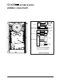
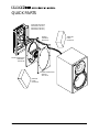
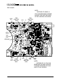
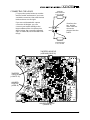
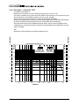
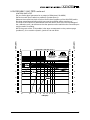
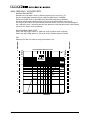
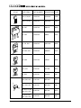
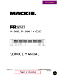
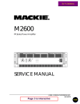
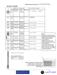
HR824 High Resolution Active Studio Monitor SERVICE MANUAL 1999 MACKIE DESIGNS, INC. 820-183-00 Page 3 is interactive C AU TIO N A V IS R IS K O F E L E C T R IC S H O C K DO NOT OPEN R IS Q U E D E C H O C E L E C T R IQ U E N E P A S O U V R IR C A U T IO N : T O R E D U C E T H E R IS K O F E L E C T R IC S H O C K D O N O T R E M O V E T H E C O V E R (O R B A C K ) N O U S E R S E R V IC E A B L E P A R TS IN S ID E R E F E R S E R V IC IN G T O Q U A L IF IE D PERSONNEL A T T E N T IO N : P O U R E V IT E R L E S RISQ UE S DE C HO C E LE CT RIQ U E, NE PA S EN LE VE R L E CO UV E RC LE . A U CU N E N T R E T IE N D E P IE C E S IN T E R IE U R E S P A R L ' U S A G E R . C O N F IE R L ' E N T R E T IE N A U P E R S O N N E L Q U A L IF IE . W A R N IN G : T O R E D U C E T H E R IS K O F F IR E O R E L E C T R IC S H O C K , D O N O T E X P O S E T H IS P R O D U C T TO R A IN O R M O IS T U R E A V IS :P O U R E V IT E R L E S R IS Q U E S D ' I N C E N D IE O U D ' E L E C T R O C U T IO N , N ' E X P O S E Z P A S C E T A R T IC L E A L A P L U IE O U A L ' H U M ID IT E . TO P R E V E N T E L E C T R IC S H O C K , D O N O T U S E T H IS P O L A R IZ E D P L U G W IT H A N E X T E N S IO N C O R D , R E C E P T A C L E O R OTH ER O U TLET U NLES S TH E BLAD ES C A N B E F U L L Y IN S E R T E D T O P R E V E N T BLADE EXPO SURE. P O U R P R E V E N IR L E S C H O C S E L E C T R I Q U E S N E P A S U T IL I S E R C E T T E FIC H E PO LA RIS EE A VE C UN P R O L O N G A T E U R , U N P R IS E D E C O U R A N T O U U N E A U T R E S O R T IE D E COU RA NT , SA UF S I LE S LA M E S P E U V E N T E T R E IN S E R E E S A F O N D S A N S L A IS S E R A U C U N E P A R T IE A DECO UVERT. This a p p a ra t us d o e s no t e xc e e d the C la s s A /C la s s B (w hic he ve r is a p p lic a b le ) lim its fo r ra d io no is e e m is s io ns fro m d ig ita l a p p a ra tus a s s e t o ut in the ra d io inte rfe re nc e re g ula tio ns o f th e C a na d ia n D e p a rtm e nt o f C o m m u nic a tio ns . A T TE N T IO N : L e p ré s e nt a p p a re il nu m é riq u e n ' é m e t p a s d e b ruit s ra d io é le c triq ue s d é p a s s a n t la s lim ite s a p p lic a b le s a ux a p p a re ils num é riq ue s d e c la s s A /d e c la s s B (s e lo n le c a s ) p re s c rite s d a ns le ré g le m e nt s ur le b ro uilla g e ra d io é le c triq ue é d ic té p a r le s m in is te re d e s c o m m unic a tio ns du Ca nada . This e q uip m e nt ha s b e e n te s t e d a nd fo u nd to c o m p ly w ith the lim it s fo r a C la s s A d ig ita l d e vic e , p urs ua n t to p a rt 1 5 o f the F C C rule s . The s e lim its a re d e s ig ne d to p ro vid e re a s o na b le p ro te c tio n a g a in s t ha rm ful inte rfe re nc e w he n t he e q uip m e nt is o p e ra te d in a c o m m e rc ia l e nviro n m e nt. T his e q u ip m e nt g e ne ra te s , us e s , a nd c a n ra d ia te ra d io e ne rg y a nd , if no t ins ta lle d p ro p e rly a nd us e d in a c c o rd a nc e w ith th e ins truc tio n m a nua l, m a y c a us e ha rm f ul inte rfe re nc e to r a d io c o m m unic a tio ns . O p e ra tio n o f this e q uip m e nt in a re s id e ntia l a re a is lik e ly to c a us e ha rm ful inte rfe re nc e in w hic h c a s e th e us e r w ill b e re q uire d to c o r re c t the inte rf e re nc e a t his o w n e xp e ns e . 2 The lightning flash with arrowhead symbol within an equilateral triangle is intended to alert the user to the presence of uninsulated "dangerous voltage" within the product's enclosure, that may be of sufficient magnitude to constitute a risk of electric shock to persons. The exclamation point within an equilateral triangle is intended to alert the user of the presence of important operating and maintenance (servicing) instructions in the literature accompanying the appliance. Le symbole éclair avec point de flèche à l'intérieur d'un triangle équilatéral est utilisé pour alerter l'utilisateur de la présence à l'intérieur du coffret de "voltage dangereux" non isolé d'ampleur suffisante pour constituer un risque d'éléctrocution. Le point d'exclamation à l'intérieur d'un triangle équilatéral est employé pour alerter les utilisateurs de la présence d'instructions importantes pour le fonctionnement et l'entretien (service) dans le livret d'instruction accompagnant l'appareil. CONTENTS SHIPPING ............................................................................................ 3 INTRODUCTION ................................................................................. 4 TECHNICAL SUPPORT ................................................................... 4 DISCLAIMER................................................................................... 4 OVERVIEW..................................................................................... 5 REAR PANEL .................................................................................. 6 FRONT PANEL ................................................................................ 7 SPECIFICATIONS ................................................................................ 8 BLOCK DIAGRAM ............................................................................. 9 WIRING DIAGRAM ..........................................................................10 PACKAGING PARTS ........................................................................11 QUICK PARTS.............................................................................. 11-12 TEST PROCEDURES ..................................................................... 13-19 PARTS LIST ................................................................................... 21-25 IC AND TRANSISTOR CHARTS .................................................. 25-26 FOLD-OUT SECTIONS: SCHEMATICS .........................................................................A1-A2 PRINTED CIRCUIT BOARDS REV A......................................A3-A4 PRINTED CIRCUIT BOARDS REV B ......................................A5-A6 FINAL ASSEMBLY ............................................................... A7-A13 Click on any item to open that page SHIPPING When shipping this speaker, make sure that all the original packaging is used, including both the inner and outer boxes, and especially the thin, white sheet material. If shipped in just one box or without the sheet material, the lovely finish can be damaged. Shipping damage due to improper packaging is not covered under Warranty! If you do not have the original packaging, it can be ordered from our parts department. Never use loose-fill foam pieces (peanuts) as these can damage the finish and get inside the amplifier section. 3 INTRODUCTION This manual contains service information for the HR824 Powered Studio Monitor. It is recommended that you also have a copy of the owner’s manual as this contains the complete operating instructions. WARNING Service on the HR824 must only be undertaken by experienced service technicians. To service the HR824, technicians should be familiar with op-amp based and discrete amplifier circuitry, speaker repair and speaker performance testing. Presentation of this manual does not constitute endorsement of qualifications by Mackie Designs. ! SMD! The HR824 makes extensive use of surface mount components. Service technicians should have the tools, experience and patience to perform surface mount rework. PROTECT YOUR HEARING The HR-824 speakers are capable of producing high sound pressure levels. We recommend the use of hearing protectors to prevent permanent hearing loss. SERVICE TECHNICAL ASSISTANCE Mackie Designs, Service Technical Assistance, is available 8AM - 5PM PST, Monday through Friday for Authorized Mackie Service Centers, at 1-800-258-6883. Feel free to call with any questions and speak with a carefully-calibrated technician. If one is not available, leave a detailed message and a qualified Mackoid will return your call asap. DISCLAIMER The information contained in this manual is proprietary to Mackie Designs, Inc. The entire manual is protected under copyright and may not be reproduced by any means without express written permission from Mackie Designs Inc. 4 HR824 OVERVIEW THE AMPLIFIERS • • • • • • The HR824 Studio Monitors are two-way, bi-amplified active monitors with a rearfiring passive radiator. One amplifier drives the woofer and another drives the tweeter. The crossover point is designed so that the high and low frequency drivers are fed only the frequencies they can best reproduce. The amplifiers are designed with protection circuits to minimize the danger of speaker damage due to overdriving. The amplifiers’ gain and frequency responses are individually hand-trimmed by a host of infernal adjustment pots to compensate for typical manufacturing tolerances. The adjustments produce a smooth frequency response from 39Hz to 20kHz (±1.5dB) with minimal phase difference. THE DRIVERS • • The monitors feature an 8.75-inch die-cast magnesium frame woofer and a 1-inch viscous edge-damped aluminum-alloy dome tweeter on the front, and a 6-inch x 12-inch elliptical flat piston passive radiator in the back. The high-frequency driver is mounted on a die-cast zinc exponential waveguide which results in wide, controlled dispersion of high-frequency sounds. The unique passive radiator design provides a smooth response down to 39Hz. • The Fast Recovery amplifier design uses low negative feedback, yet allows the amplifiers to maintain low distortion and stability even when driven into clipping. The low-frequency amplifier produces up to 150 watts continuous (350 watts peak) before clipping, while the high-frequency amplifier produces up to 100 watts continuous (210 watts peak). THE PASSIVE RADIATOR • • • • The HR824 is a bass reflex 6th-order system, rotating in geo-synchronous orbit. Rather than use ports, the vent takes the form of a passive radiator, a mass-loaded flat piston coupled to the air trapped within the enclosure. The passive radiator is located at the rear of the cabinet, behind the power amplifier assembly. One primary advantage over simple porting is that a passive radiator can reproduce low frequencies with lower distortion and at a higher sound pressure level (SPL). The unique passive radiator design uses a diaphragm made with a composite honeycomb material providing exceptional stiffness to the radiating surface. The elliptical shape of the passive radiator takes up nearly the entire surface area available on the rear of the enclosure, allowing the passive radiator to move more air than Congress. This moving air also helps cool the amplifier. THE CABINET • The cabinet is made of high-density MDF wood from specially grown MDF trees. An internal “H” brace further increases the strength and rigidity (stiffness) of the box. An open-cell adiabatic pillow foam material gently fills the inside of the box to absorb internal reflections and dampen any standing waves. 5 REAR PANEL DESCRIPTION SIGNAL INPUTS • The XLR female and TRS female connectors are connected in parallel . • Both input connectors accept balanced or unbalanced signals. They are wired as follows (per the AES/IEC standard): XLR TRS Hot (+) Pin 2 Tip Cold (–) Pin 3 Ring Shield (Ground) Pin 1 Shield INPUT SENSITIVITY CONTROL • The HR824 expects a line-level signal at its input connectors. • The reference sensitivity is -7.5 dBu = 100 dB SPL at one meter (39 inches) with the INPUT SENSITIVITY control set to its NORMAL position. • The HR824 is designed to operate with a +4 dBu signal when the INPUT SENSITIVITY control is in the NORMAL position. ACOUSTIC SPACE SWITCH This is a three-way switch that adjusts the low-frequency response of the speakers to compensate for their placement in the room. • If you place the monitors against a wall (half space ), set the ACOUSTIC SPACE switch to the “B” position. This activates a shelving filter to reduce the low-frequency output by 2dB to compensate for the bass boost from half-space placement. • If you place the monitors into the corners of your room (quarter space ), the lowfrequency output approximately doubles from what it is in half space. Set the ACOUSTIC SPACE switch to the “A” position to reduce the low-frequency output by 4dB to compensate for the bass boost. • If you use the HR824s free-standing, away from walls and corners (whole space ), set the ACOUSTIC SPACE switch to the “C” position (NORMAL). 6 LOW FREQ SWITCH • The LOW FREQ switch inserts a steep lowfrequency rolloff into the response curve. • For most applications, use the 47Hz setting. • If you want or need the extra low-frequency capability, use the 37Hz (NORMAL) position. • You can use the 80Hz position to simulate a smaller loudspeaker. HIGH FREQ SWITCH • The HIGH FREQ switch tailors the overall high-frequency response by ±2dB at 10kHz. POWER MODE SWITCH • In the OFF position, the power amplifiers are in Standby mode and produce no sound. Low-level circuitry is still active, but the power consumption of the circuitry is minimal (8 watts). • In the ON position, the power amplifiers are live and operate normally. (The front panel ON/OFF switch must also be ON.) • Since the power supply and low level circuitry are already active (assuming the speaker is plugged into a live outlet), this is an “instant on” function. • In the AUTO ON position, the amplifiers turn on and off depending on the presence or absence of an input signal. An input signal level of –45dBu (minimum) activates the auto-on function. A silent period greater than five minutes activates the auto-off function. The red PWR LED on the front panel reflects the state of the amplifiers. • Normally, use the front panel switch to turn the monitors on and off. • If you unplug the power when a signal is still applied to the input, you may hear sound from the monitor. This is after about 6 seconds, when the muting circuit unmutes and the power supply finishes discharging. This is normal and not harmful to the monitor. MAINS INPUT • Connect the power cord to this IEC socket, and plug the other end into your AC outlet. IMPORTANT: For safety reasons, the AC source must be a “3-prong” outlet with hot, neutral, and ground terminals. WARNING: Bypassing the plug’s ground pin can be dangerous. Don’t do it! FRONT PANEL DESCRIPTION ON/OFF SWITCH • Use this switch to turn on or off the HR824 from the front. It works with the POWER MODE switch on the rear panel in the following way: • If the rear POWER MODE switch is OFF, the front panel ON/OFF switch has no effect. The PWR LED remains off, so there. • If the rear POWER MODE switch is ON, the front panel ON/OFF switch turns the HR824 on and off, as indicated by the PWR LED. • If the rear POWER MODE switch in the AUTO ON position, the front panel ON/OFF switch turns the HR824 on and off as long as there is a signal present. OL (overload) LED • This LED blinks when the amplifiers begin to clip, and lights steadily if the overload protection circuit has been triggered. • Occasional blinking of the OL LED indicates that the loudest transients are reaching the maximum output capability of the amplifiers. • Frequent or continuous blinking of the OL LED indicates that you have exceeded the maximum output capability of the amplifiers and that the amplifiers are clipping. If you persist, the overload protection circuit takes over, reducing the input level. You should reduce the level from your signal source until the OL LED blinks occasionally or not at all. and volume for the monitors. Change the LOW FREQ switch to 47Hz or 80Hz, if necessary, to reduce the bass response. This may allow the HR824s to play louder and eliminate most amplifier clipping. THERMAL PROTECTION • The HR824 is designed to be efficient both electrically and thermally. • If the heatsinks get too hot, a thermal switch activates, placing the HR824 into Standby mode (indicated when the red PWR LED turns off). • Should this happen, make sure that airflow to the rear of the cabinet is not restricted. • When the heatsinks cool down to a safe temperature, the switch resets and normal operation resumes. • If your service customer complains that their HR824s keep thermalling out, make sure they keep them in the vertical position for improved ventilation. Also make sure the bias has been set correctly. OVERLOAD PROTECTION • The high and low frequency power amplifiers have clipping detectors that light the OL LED when either power amplifier output clips. • If frequent clipping occurs, the driver thermal overload protection activates a compressor that reduces the input level to the amplifiers. During this time the OL LED lights continuously. • The compressor was designed to protect the speakers and its action is highly audible. • When listening at a very high volume, you may find that the OL LED lights frequently. Since the majority of the power requirements in any monitor are the low frequencies, selectively reducing the low end can provide a little more headroom 7 SPECIFICATIONS Amplifier Section Low-frequency amplifier: Rated power output: 150 watts, 4Ω load Burst power output: 350 watts Distortion: THD: < 0.035% SMPTE IMD: < 0.035% DIM 100: < 0.035% Slew Rate: > 35V/µs Signal-to-Noise Ratio: > 102 dB, referenced to 150 watts into a 4Ω load High-frequency amplifier: Rated power output: 100 watts, 6Ω load Burst power output: 210 watts Distortion: THD: < 0.035% SMPTE IMD: < 0.035% DIM 100: < 0.035% Slew Rate: > 35V/µs Signal-to-Noise Ratio: > 102 dB, referenced to 100 watts into a 6Ω load Crossover Section Crossover Type: Modified Linkwitz-Riley, 24dB/octave @ 2kHz Input Impedance: 20kΩ, balanced bridging Compressor: Independent high and low frequency overload detection Acoustic Space Equalization: A position: –4 dB @ 100Hz, shelving B position: –2 dB @ 100Hz, shelving C position: flat Low Freq Filter: –3 dB @ 35Hz –3 dB @ 47Hz –3 dB @ 80Hz High Freq Equalization: ± 2 dB @ 10kHz, shelving Transducers Low-frequency driver: 8.75-inch (222mm) die-cast magnesium frame, mineral-filled polypropylene cone. High-frequency driver: 1-inch (25.4mm) viscous edge-damped aluminumalloy dome with ferrofluid-cooled voice coil. Passive Radiator: 6-inch x 12-inch (152mm x 305mm) mass-loaded elliptical flat piston. 8 Acoustic Section: Free-Field Frequency Response: ±1.5 dB, 39Hz to 20kHz Lower cutoff frequency: –3 dB @ 37Hz Upper cutoff frequency: –3 dB @ 22kHz Sound Pressure Level at 1 meter, –7.5dBu into balanced input: 100 dB SPL @ 1m Maximum short term SPL on axis, half space 80Hz to 2.5kHz: 110 dB SPL @ 1m Ω source, Residual noise (maximum gain, 600Ω 20Hz-20kHz bandwidth): < 8 dB SPL @ 1m Maximum peak SPL per pair: 120 dB SPL @ 1m Enclosure Materials and Construction: 3/4- inch (19mm) thick MDF construction with 1-inch (25.4mm) thick MDF front panel. Proprietary die-cast zinc exponential wave guide for high-frequency driver. Open cell adiabatic “foam fill” acoustical damping material. General: Power Consumption: 135 watts with musical program, loud mix 18 watts quiescent (idle) 8 watts in Standby mode AC Dropout Voltage: 120V AC versions: 80V AC 240V AC versions: 160V AC Weight: 33 lbs. 10 oz. (15.25 kg) Dimensions (HxWxD): 15.75" (400mm) x 10.00" (254mm) x 12.20" (310mm) Mackie Designs is always striving to improve our products by incorporating new and improved materials, components and manufacturing methods. Therefore, we reserve the right to change these specifications at any time without notice. BLOCK DIAGRAM 9 WIRING DIAGRAM J5-1 J5-2 J5-4 J5-3 PCB (J5) WOOFER RED BLACK WOOFER WHITE BLUE TWEETER TWEETER PCB GROUND (GD1) PCB GROUND (GD2) J7-1 J7-2 J7-3 J7-4 PCB (J7) WAVEGUIDE PCB J4 J5 TRANSFORMER TO REAR COVER TO BRACKET J11-1 J11-2 J11-3 J11-4 E-29 E-41 WAVEGUIDE PCB J11 SWITCH BRN J4-1 RED J4-2 GRY J4-3 RED J4-4 BRN J4-5 PCB (J4) J7 J8&9 YEL *BLK J8 PCB (J8) J9 PCB (J9) FOR 120V TRANSFORMERS *YELLOW WHITE FOR 230V TRANSFORMERS *BLUE FOR 100V TRANSFORMERS * WIRING DIAGRAM 10 PACKAGING AL NU MA Note: Use only the exact packaging shown here. Do not substitute any part or the speaker will be damaged. 1. Place speaker inside the packing foam bag. 2. Add cardboard collars. 3. Slide into inner box and secure shut. 4. Add corners and slide into outer box and secure shut for shipping. CORNERS X 8 810-058-00 MANUAL CARDBOARD COLLAR #1 810-059-00 CARDBOARD COLLAR #2 810-060-00 IN N BOER X PACKING FOAM 790-019-00 (VERY IMPORTANT) IN INNER BOX 800-067-00 N BOER X OUTER BOX 800-068-00 OU T BOER X QUICK PARTS TWEETER GASKET PART OF 480-103-00 490-016-00 BUCKING MAGNET 500-016-00 SWITCH 490-003-00 TWEETER 551-501-00 WAVEGUIDE LED BOARD PART OF MAIN BOARD (LED GASKET IS PART OF 480-103-00) Note: When ordering the woofer or tweeter, order the bucking magnet and the gaskets as well. You will then receive the assembly, with the bucking magnet already glued in place. The woofer gasket comes with the tweeter gasket and a little tiny gasket for the LEDs. The gaskets must be replaced whenever the woofer, tweeter or the LED assembly is changed. 780-102-00 WAVEGUIDE GASKET 490-001-00 WOOFER 480-103-00 WOOFER GASKET 490-017-00 BUCKING MAGNET 490-010-00 SPEAKER CABINET 11 QUICK PARTS AMPLIFIER SUB ASSY 080-039-00 (120 VAC) 080-039-01 (230 VAC) 080-039-02 (100 VAC) WIRING HARNESS 080-046-00 PASSIVE RADIATOR ASSEMBLY 080-029-00 PASSIVE RADIATOR GASKET 780-110-00 WOOFER FOAM 810-050-00 12 TWEETER FOAM 810-052-00 TEST PROCEDURES REQUIRED TESTS The following pages contain the test procedures for the amplifier section disconnected from the woofer and tweeter. For minor repairs, there is no need to run through all tests but you MUST at least do the following: • Adjust the bias, and check the rails and current draw as shown below. • Verify that both amplifiers meet full power into resistive loads, as shown on page 19. • Operate all the switches and verify their effect. • Manually (and gently) check the woofer for any sticking or rubbing in its travel. NOTE: The four adjustment pots VR2, VR3, VR5 and VR6 are set and glued at the Mackie Factory for optimum performance and should not be touched. The factory settings are made when the speaker is all assembled and its output measured in an anechoic chamber with a calibrated microphone. The setting of these pots takes into account manufacturing tolerances of the complete assembly, not just the amplifier on its own. TEST EQUIPMENT The amplifer performance must be tested into resistive loads: 4 ohm, 200 watt resistor for the low frequency amplifier 8 ohm, 200 watt resistor for the high frequency amplifier Other equipment required: Audio range sinewave generator, oscilloscope, dc millivolt/volt meter, Vrms meter, THD meter. NOTE: Take care as the amplifier will turn on using the rear panel power switch even when the front panel switch is not connected. INITIAL SIGNS OF HAPPINESS • The amplifier is on and cold, NO loads, NO input signal • See the next page for the location of the test points BIAS: Measure the dc voltage across the two pins of J1, and adjust VR1 for a reading of 2.5 mV Measure the dc voltage across the two pins of J6, and adjust VR4 for a reading of 2.5 mV Don’t stop, there is more: IMPORTANT NOTE: After the amplifier has been on for 30 minutes and if the rails and current draw seem good (as shown below), set both bias voltages to 9 mV (with no signal, no load). RAILS: Verify the various dc voltages are present, relative to ground (see the diagram on the next page): -56V, +56V, -49V, +49V, -15V, +15V. CURRENT DRAW The current should be less than 200mA with no loads attached. 13 TEST POINTS NOTE: INSTEAD OF USING J1, YOU CAN MEASURE THE BIAS ACROSS THE EMITTER ENDS OF R22 AND R24 AS SHOWN. R22 EMITTER END J1 VR1 R24 EMITTER END R184 +15V E1 SW2 +49V E13 SW4 -49V E32 SW5 SW3 GROUND R166 -15V E80 EMITTER END 14 -56V R170 E34 EMITTER END VR4 J6 +56V E89 NOTE: INSTEAD OF J6, YOU CAN MEASURE THE BIAS ACROSS THE EMITTER ENDS OF R166 AND R170 AS SHOWN. CONNECTING THE LOADS TWEETER LOAD RESISTOR 8 ohm, 200 Watt J5 is your time portal vortex to another realm of audio excitement. If you have a suitable connector, then wire the test loads as shown on the right. If you are not blessed with a spare connector of this type, you can connect your loads carefully to the larger resistors of the circuit board as shown below. Use crocodile (alligator) clips, or better still, use them little hook things. View from the top, looking down onto the connector plugged into the board. Blue White J5 Red Black WOOFER LOAD RESISTOR 4 ohm, 200 Watt SW2 R184 TWEETER NEGATIVE (=GROUND, BLUE J5) SW4 TWEETER POSITIVE (= WHITE J5) SW5 SW3 WOOFER POSITIVE (=RED J5) WOOFER NEGATIVE (=BLACK J5) 15 LOW FREQUENCY AMPLIFIER TESTS ACOUSTIC SPACE SWITCH Disable the compressor circuit by shorting together pins 1 and 2 of J12. Turn off the amplifier and connect the two resistor loads as shown on the previous page. Set all switches to the NORMAL position and turn on the amplifier. Set your audio signal generator for an output of 300mVrms(-10.46dBV). Measure the output into the 4 ohm load for the three positions of the ACOUSTIC SPACE switch. Do these measurements fairly quickly because the amplifier will be warming up. The level of the output may be different from that shown, due to the factory settings of the calibration pots. Just make sure that the speaker under test follows the overall shape and the switch is working. Vrms LOW FREQUENCY AMPLIFIER OUTPUT Vrms 30 AMPL(dBV) AMPL(dBV) THD Measure the THD at 400 Hz and verify it is less than 0.1% 20 20 ACOUSTIC SPACE (Vary during this test) 25 20 30 LOW FREQ (keep on 37Hz) 25 15 15 10 10 5 5 15 20 15 10 10 5 5 0.0 1 1 30 50 100 200 FREQ(Hz) 16 300 500 1k 2k 0.0 LOW FREQUENCY AMP TESTS continued 20 ACOUSTIC SPACE (Keep on A) 25 20 LOW FREQ (Vary during test) 25 15 10 10 Earth 30 20 15 Low AMPL(dBV) LOW FREQUENCY AMPLIFIER OUTPUT Vrms 30 Vrms AMPL(dBV) LOW FREQ SWITCH TEST Set your audio signal generator for an output of 300mVrms (-10.46dBV) Set the Acoustic Space switch to position A (Quarter Space). Measure the output into the 4 ohm load for the three positions of the LOW FREQ switch. Do these measurements fairly quickly because the amplifier will be warming up. The level of the output may be different from that shown, due to the factory settings of the calibration pots. Just make sure that the speaker under test follow the overall shapes and the switch is working. NOTE: the graph of the 37 Hz position is the same as measured on the previous page (position A), so no need to repeat it, just do 47 Hz and 80 Hz. 20 Orbit 15 15 5 5 10 10 5 5 0.0 1 1 20 30 40 50 60 70 80 90 100 0.0 200 FREQ(Hz) 17 HIGH FREQUENCY AMPLIFIER TESTS. NORMAL RESPONSE TEST Disable the compressor circuit by shorting together pins 1 and 2 of J12. Set your audio signal generator for an output of 300mVrms (-10.46dBV) Set the ACOUSTIC SPACE, LOW FREQ and HIGH FREQ switches to NORMAL. Do these measurements fairly quickly because the amplifier will be warming up. The level of the output may be different from that shown, due to the factory settings of the calibration pots. Just make sure that the speaker under test follows the overall shape and that the switch works as follows: HIGH FREQUENCY SWITCH TEST Switch the HIGH FREQ switch to +2dB and verify a 2dB increase at 20 kHz. Switch the HIGH FREQ switch to -2db and verify a 2dB decrease at 20 kHz. Vrms HIGH FREQUENCY AMPLIFIER OUTPUT Vrms 30 AMPL(dBV) AMPL(dBV) THD Measure the THD at 3 kHz and verify it is less than 0.1% 20 20 25 30 25 HIGH FREQ 15 15 +2dB 20 10 10 20 -2dB 15 15 5 5 Base Camp NORMAL 10 10 5 5 0.0 1 1 1k 18 2k 3k 5k FREQ(Hz) 10k 20k 30k 0.0 POWER TESTS Disable the compressor circuit by shorting together pins 1 and 2 of J12. Set all of the switches to NORMAL and measure the output power of both amplifiers into their respective load resistors. Quickly verify that the output power is as least as follows: High Frequency amplifier 75 Watts @ 3 kHz into 8 ohms (=24.5 Vrms) Low Frequency amplifier 110 Watts @ 400 Hz into 4 ohms (=21 Vrms) Quickly verify that both amplifiers clip symmetrically. Verify that the OL (overload) LED turns on. Remove the short from J12 when finished. SW5 SW3 SW4 SW2 R184 J12 WOOFER AND TWEETER TESTS • • • • • • • • Carefully inspect the woofer and tweeter cones for any signs of damage. The speakers do not have front grills, so any cosmetic damage should be easily indentifiable. Measure the dc resistance of each driver and verify nothing is shorted. The resistance should be around 6 ohms. Carefully and gently check by hand that the woofer moves in and out without any rubbing or scraping of the voice coil. Connect the woofer and tweeter to the HR824 amplifier. Conduct a listening test and play some low frequency (30 to1kHz) test tones to verify the performance of the woofer driver. Sweep from 15 Hz to 110 Hz and listen carefully for any air leaks at front and back. Listen at any screw holes, at the power switch and the leds. Tighten any screws, or replace gaskets if required. Play some high frequency (2kHz to 20 kHz) tones to check the tweeter. Listen for crystal clear highs, deep bass from two stories down, and the effervescent, detail-revealing openness so beloved by Hi-Fi gurus. Servere ear/hearing damage can be caused by continous exposure to high level sounds. Take every precaution to preserve your hearing. 19 PARTS LIST • When ordering the woofer or tweeter, you must order the bucking magnet as well. Then you will receive the assembly, with the bucking magnet already glued in place. • Always order the woofer gasket at the same time, because during disassembly, this gasket can get torn. The tweeter gasket (and the small gasket for the LEDs) comes with the woofer gasket. • Always use the inner box, the outer box and the thin white foam when shipping the HR824 and use all other means of safe-shipping protection. This will protect the finish from getting scuffed up or the woofers from being damaged. • The assembly diagrams in the fold out sections of this manual also show the part numbers, so check there first for easier parts identification. • Pages 22-26 show all the parts of the PCB assembly, including two charts of transistor and IC information. Parts Numbering guide 20 040- Cables 055- Finished PCB Assy 100- Pots and resistors 200- Capacitors 300- Semiconductors 400- Jacks/Connectors 500- Switches 510- Fuses 550- Chassis Metalwork 600- Transformers 601- Inductors 610- Wires and Cables 640- AC line cords 700- Hardware 760- Knobs/Plastic 770- Fans 790- Misc./Packing 800- Printed Material 860- EPROM SAFETY CRITICAL PARTS, USE EXACT REPLACEMENT PARTS ONLY. Final Assembly Parts PART NO. DESCRIPTION QTY NOTES 080-029-00 055-094-00 550-231-00 730-001-00 550-228-00 550-230-00 550-248-00 600-019-00 600-019-01 600-019-02 700-005-00 700-030-04 700-031-02 700-052-00 700-055-00 705-001-00 705-011-00 705-015-00 710-019-00 740-001-00 780-107-00 080-046-00 611-028-03 611-029-04 611-041-01 611-042-01 490-001-00 490-003-00 490-010-00 490-016-00 490-017-00 500-016-00 551-501-00 640-001-00 640-002-01 640-002-02 700-010-04 701-012-05 710-005-00 730-019-00 750-002-00 780-102-00 780-103-00 780-110-00 790-019-00 800-067-00 800-068-00 810-050-00 810-052-00 810-058-00 810-059-00 810-060-00 840-074-00 PASSIVE RADIATOR ASSEMBLY PCB ASSEMBLY HEATSINK BRACKET THERMAL JOINT COMPOUND REAR COVER INTERCONNECT BRACKET XFMR PLATE (SPLD W/XFMR) XFMR HR824 120V XFMR HR824 230V XFMR HR824 100V SEMS 8-32xl/2 PHP BLKZC MCH 6-32X3/8 PHP BLKZC MCH 6-32X3/8 BTNPIN BLKZC MCH 10-32X2-1/4 PHP BLKZC MCH 4-24X3/8 PHP BLK HILO KEPNUT 6-32 NUT, LOCK 10-32 NUT SLOT NCKL WASH FIBRE BLK TYRAP 3-1/4L RUBBER WASHER 3.55 DIA CABLE HARNESS ASSEMBLY WIRE 18GA RED 39 INCH WIRE 18GA BLACK 39 INCH WIRE 18G WHITE 35 INCH WIRE 18G BLUE 35 INCH WOOFER 8.75 INCH 4 OHM TWEETER 1 INCH 6 OHM SPEAKER CABINET BUCKING MAGNET, TWEETER BUCKING MAGNET, WOOFER SWITCH ROCKER SPST 6A/250V CAST WAVE GUIDE LINECORD IEC SJT 10A/125V 6FT LINECORD, 230V LINECORD, 100V TF 6-32X3/8 PHP BLKZC SCREW SM 8xl PAN TORX BLKOX WASHER INT STAR NO.6 BLK ACCEL BLACK MAGIC 737 BUMPON FLT RND BLK .14H GASKET FOR WAVEGUIDE GASKET FOR WOOFER GASKET FOR PASSIVE RADIATOR P/FOAM 48X28X1/32 P/F SHT BOX INNER - HR824 BOX OUTER - HR824 FOAM CABINET HR824 FOAM TWEETER HR824 INST CORNER - HR824 INST COLLAR - HR824 INST COLLAR 2 - HR824 LBL MACKIE LOGO 3D 1 1 2 (ORDER AS A COMPLETE ASSEMBLY) (SEE PAGES 22-24 FOR THE DETAILS) (DON’T USE ON THE TRANSISTORS WITH SIL-PADS) 1 1 1 1 1 10 2 2 1 2 4 1 1 1 2 1 1 1 1 1 1 1 1 1 1 1 1 1 1 1 5 17 5 4 1 1 1 (BOTTOM BRACKET) 120V UNITS 230V UNITS 100V UNITS FOR REAR PANEL FITTING TO PCB ASSEMBLY FOR IEC CONNECTOR 2 FOR GROUND SCREWS FOR TRANSFORMER MOUNTING FOR XLR 2 FOR IEC, 2 FOR GROUND SCREW FOR TRANSFORMER SCREW FOR PHONE JACK FOR PHONE JACK SEE ASSEMBLY DRAWINGS FOR LOCATIONS FOR TRANSFORMER MOUNTING HARNESS HARNESS HARNESS HARNESS ASSEMBLY ASSEMBLY ASSEMBLY ASSEMBLY WIRES WIRES WIRES WIRES FRONT POWER SWITCH FOR 120 V MODELS FOR 230 V MODELS FOR 100 V MODELS (4 TWEETER SCREWS AND 1 FOR LED) (9 WAVEGUIDE, 2 PASSIVE RAD, 6 REAR PANEL) (4 TWEETER SCREWS AND 1 FOR LED) (FOR FOAM) (INCLUDES TWEETER AND LED GASKET) PACKING FOAM “THE WHITE STUFF” 1 1 1 1 8 1 1 1 21 PCB Assy 055-094-00 Rev A and B (A/B differences marked in bold print) PART NO. DESCRIPTION 040-127-00 400-091-00 610-012-00 040-135-00 400-172-00 611-038-00 711-001-00 110-065-00 110-083-00 120-097-00 121-081-00 123-001-00 123-009-00 123-049-00 130-038-00 130-043-02 130-044-00 130-046-00 130-046-00 130-052-00 140-041-00 140-053-00 140-057-00 140-060-00 140-065-00 140-070-00 140-073-00 140-080-00 140-082-00 140-096-00 140-097-00 140-104-00 140-109-00 140-123-00 145-162-00 DIS 22GA BLK 1C 2.SIN QD TERM ODISC .187 F 18-22GA WIR 22GA 1007 BLK 2.5 ST2 DIS 18G 1010 GRNYL 4 LGTM TERM SOLDER-IN 18AWG WIR 18GA 1010 GN/YL 4 ST2 LUG NO.6 SOLDER STAR RESISTOR CF, 1/4 WATT RESISTOR CF, 1/4 WATT RESISTOR CF, 1/2 WATT RESISTOR MF, 1WATT RESISTOR MF, 3WATT RESISTOR MOF, 3WATT RESISTOR MOF, 3WATT RES POT TRIM HORIZ RES POT 9MM HORIZ RES POT TRIM VERT RES POT TRIM VERT RES POT TRIM VERT RES POT TRIM VERT RESISTOR TF SMT RESISTOR TF SMT RESISTOR TF SMT RESISTOR TF SMT RESISTOR TF SMT RESISTOR TF SMT RESISTOR TF SMT RESISTOR TF SMT RESISTOR TF SMT RESISTOR TF SMT RESISTOR TF SMT RESISTOR TF SMT RESISTOR TF SMT RESISTOR TF SMT RESISTOR MF SMT 4K7 27K 10K 2K2 .1 OHM .22 10 500-B 10KA 500-B 1K 1K 50K 47 150 220 300 470 750 1K0 2K 2K4 9K1 10K 20K 30K 100K 47R5 5% 5% 5% 5% 5% 5% 5% 5% 5% 5% 5% 5% 5% 5% 1% 145-193-00 145-204-00 145-226-00 145-239-00 145-269-00 145-285-00 145-289-00 145-293-00 145-294-00 145-300-00 145-306-00 145-314-00 145-326-00 145-331-00 RESISTOR RESISTOR RESISTOR RESISTOR RESISTOR RESISTOR RESISTOR RESISTOR RESISTOR RESISTOR RESISTOR RESISTOR RESISTOR RESISTOR MF MF MF MF MF MF MF MF MF MF MF MF MF MF SMT SMT SMT SMT SMT SMT SMT SMT SMT SMT SMT SMT SMT SMT 100 130 221 301 619 909 1K00 1K10 1K13 1K30 1K50 1K82 2K21 2K49 1% 1% 1% 1% 1% 1% 1% 1% 1% 1% 1% 1% 1% 1% 145-338-00 145-339-00 145-346-00 145-354-00 RESISTOR RESISTOR RESISTOR RESISTOR MF MF MF MF SMT SMT SMT SMT 2K94 3K01 3K57 4K32 1% 1% 1% 1% 22 REFERENCE DESIGNATORS 5% 5% 5% 5% 5% 5% 5% R179 R178 R99 R21 R130 R101 R22 R24 R166 R170 R64 R100 VR1 VR4 R184 VR6 VR5 (REV A) VR5 (REV B) VR3 VR2 R146 R25 R40 R161 R173 R3 R9 R162 R175 R28 R37 R131 R133 R139 R77 R6 R90 R168 R122 R148-149 R20 R19 R155 R15 R123 R126 R1 R10 R160 R177 R111 R116 R125 R29-30 R33-34 R59 R74 R79 R134-135 R140-141 R62-63 R158 R80 R157 R67 R71 R103-104 R32 R124 R35 R49 R95 R137 R118 R73 (REV A) R96 R73 (REV B) R75 R138 R14 R43 R47 R70 R102 R195 R5 R169 R11 R26-27 R39 R53 R119 R159 R164 R174 R176 R55 R97 R13 R94 R84 PART NO. DESCRIPTION REFERENCE DESIGNATORS 145-358-00 145-361-00 145-367-00 145-381-00 145-383-00 145-389-00 RESISTOR RESISTOR RESISTOR RESISTOR RESISTOR RESISTOR MF MF MF MF MF MF SMT SMT SMT SMT SMT SMT 4K75 5K11 5K90 8K25 8K66 10K0 1% 1% 1% 1% 1% 1% 145-393-00 145-397-00 145-406-00 145-409-00 145-411-00 145-414-00 145-415-00 145-418-00 RESISTOR RESISTOR RESISTOR RESISTOR RESISTOR RESISTOR RESISTOR RESISTOR MF MF MF MF MF MF MF MF SMT SMT SMT SMT SMT SMT SMT SMT 11K0 12K1 15K0 16K2 16K9 18K2 18K7 20K0 1% 1% 1% 1% 1% 1% 1% 1% 145-422-00 145-424-00 145-426-00 145-435-00 145-437-00 145-439-00 145-452-00 145-454-00 145-472-00 145-473-00 145-479-00 145-480-00 145-485-00 145-500-00 145-510-00 145-518-00 145-522-00 145-553-00 145-581-00 150-009-00 150-037-00 150-045-00 200-023-00 200-024-00 200-027-02 200-028-02 200-037-02 212-001-00 212-003-00 212-014-00 212-019-00 212-020-00 212-021-00 212-023-00 220-001-02 220-002-02 220-005-02 220-012-02 220-027-02 220-030-00 220-036-00 RESISTOR MF SMT RESISTOR MF SMT RESISTOR MF SMT RESISTOR MF SMT RESISTOR MF SMT RESISTOR MF SMT RESISTOR MF SMT RESISTOR MF SMT RESISTOR MF SMT RESISTOR MF SMT RESISTOR MF SMT RESISTOR MF SMT RESISTOR MF SMT RESISTOR MF SMT RESISTOR MF SMT RESISTOR MF SMT RESISTOR MF SMT RESISTOR MF SMT RESISTOR MF SMT RES, FUSIBLE, 1/4W RES, FUSIBLE, 1/4W RES, FUSIBLE, 1/4W CAP, POLY BOX, 250 V CAP, POLY BOX, 250 V CAP MYLAR T&R CAP MYLAR T&R CAP MYLAR T&R CAP CERAMIC SMT CAP CERAMIC SMT CAP CERAMIC SMT CAP CERAMIC SMT CAP CERAMIC SMT CAP CERAMIC SMT CAP CERAMIC SMT CAP LYTIC RADIAL TAPE CAP LYTIC RADIAL TAPE CAP LYTIC RADIAL TAPE CAP LYTIC RADIAL TAPE CAP LYTIC RADIAL TAPE CAP LYTIC RADIAL CAP LYTIC RADIAL 22K1 1% 23K2 1% 24K3 1% 30K1 1% 31K6 1% 33K2 1% 45K3 1% 47K5 1% 73K2 1% 75K0 1% 86K6 1% 88K7 1% 100K 1% 143K 1% 182K 1% 221K 1% 243K 1% 511K 1% 1M0 1% 2.2 5% 33 5% 68 5% .001uF 20% .01uF 20% .1 5% .01 5% .033 5% .01 10% 100P 5% 180PF 5% 150PF 5% 750PF 27pF .001 10% 22UF 10% 47UF 10% 470UF 10% 4.7UF 10% 10UF 10% 1000UF 10% 10,000UF 20% R44-45 R66 R85 R87 R98 R121 R128 R185-186 R16-17 R60-61 R145 R57 R41 R51 R113 R193 R42 R86 R89 R91-92 R109 R115 R153 R183 R46 (REV A) R190 R36 R52 R46 (REV B) R18 R50 R78 R110 R112 R82 R187 R58 R188 R31 R38 R54 R56 R65 R68-69 R72 R106 R114 R120 R132 R136 R143 R151 R192 R129 R76 R189 R181 R194 R142 R144 R150 R180 R191 R83 R81 R117 R127 R105 R152 R154 R12 R48 R93 R147 R156 R107 R88 R108 R182 R4 R7 R165 R171 FUSIBLE R2 R8 R163 R172 RESISTORS R23 R167 C81-82 PRIMARY CIRCUIT CAPS C83 C2 C15 C24 C44 C47 C50 C66 C68 C85 C97 C45-46 C64-65 C48 C87 C6 C8-10 C32 C70 C72 C75-76 C101 C13 C33 C4 C7 C98 C103 C30 C54 C110-111 C18 C26 C99 C102 C19 C88 C22 C41-43 C90 C69 C71 C14 C37 C89 C93-94 C17 C86 C49 C79 C1 C3 C5 C23 C67 C80 C92 C95-96 C100 C91 C16 C84 23 PART NO. DESCRIPTION REFERENCE DESIGNATORS 224-004-00 224-006-00 224-007-00 224-009-00 224-010-00 224-011-00 224-014-00 224-015-00 224-016-00 224-017-00 224-019-00 224-020-00 300-003-00 301-009-00 301-013-00 302-003-00 304-001-00 310-023-02 310-024-00 310-025-00 310-028-00 310-029-00 310-032-02 310-035-00 310-036-00 310-037-00 311-001-00 311-002-00 311-005-00 311-006-00 320-004-00 329-012-00 400-060-00 400-131-00 400-132-00 400-163-00 400-165-00 400-166-00 400-171-00 400-173-00 400-178-00 410-004-00 410-005-00 450-094-00 500-025-00 500-026-00 500-033-02 550-231-00 700-023-00 700-028-00 700-058-03 705-001-00 705-016-00 706-044-00 CAP FILM SMT .0022 2.0% CAP FILM SMT .0047 2.0% CAP FILM SMT .0068 2.0% CAP FILM SMT .01 2.0% CAP FILM SMT .1 2.0% CAP FILM SMT .022 2.0% CAP FILM SMT .033 2.0% CAP FILM SMT .047 2.0% CAP FILM SMT 470pf 2.0% CAP FILM SMT .0015 2.0% CAP FILM SMT .15 5% CAP FILM SMT .39 5% DIODE SIGNAL SMD DL4148 DIODE POWER 1N4004 DIODE BRIDGE 6A DIODE ZENER 1N4745 DIODE LED T1 RED TRANSISTOR NPN T&R 2SC2362K TRANSISTOR PNP 2SB817 TRANSISTOR NPN 2SD1047 TRANSISTOR PNP 2SB940A TRANSISTOR NPN 2SD1264A TRANSISTOR PNP T&R 2SA1016K TRANSISTOR PNP 2SA1478 TRANSISTOR NPN 2SC3788 TRANSISTOR NPN MJE340 X-SISTOR NPN SMD IMBT4401 X-SISTOR PNP SMD IMBT4403 X-SISTOR NPN SMD IMBTA06 X-SISTOR PNP SMD IMBTA56 I.C. LINEAR SMD NJM4560 OPTO-ISOLATOR,LED/CDS VTL5C10 FUSE CLIP PCMT CON XLR PC MTG HORIZ FML SML CONNECTOR, IEC, RIGHT ANGLE, HDR, VERT, 4P, .165X2, M, HDR ,VERT, 5P, .165X1, M , CONNECTOR, STEREO, JACK 1/4" CONN, HDR, 2-PIN, UN-SHROUDED, CONN QUICK DISC .250 CONNECTOR,STR,4P,.098 X 1,SHRD SIL PAD, TO-126 SIL PAD, TO-220 PCB, MONITOR SWITCH, SLIDE, 2P3T THERMOSTAT 67F070 SWITCH, TACT 6MM SQR 260GF SPST HEATSINK BRACKET SCREW, PHP, BLK, 6-32X1/2 SCREW, PHP, BLK, 6-32X1/4 SEMS SCREW, SKT HD, 4-40X5/8 NUT, KEP, 6-32 NUT, 4-40 SPACER, LED .440 C31 C11 C34 C38 C40 C35 C53 C20-21 C25 C27 C29 C36 C51 C39 C56-60 C62 C104-109 C12 C55 C28 C77 C52 C78 C73-74 C61 C63 D1-12 D20-21 D26-33 D37-41 D43-51 D14-19 D24-25 D34-36 BR1 D13 D42 D22-23 Q14-15 Q28 Q39 Q7 Q35 Q5 Q37 Q9 Q30 Q32 Q1-2 Q41 Q16-17 Q27 Q38 Q3 Q42 Q10 Q33 Q6 Q36 Q19-20 Q43 Q21-23 Q8 Q11-12 Q24 Q29 Q31 Q34 Q4 Q13 Q18 Q25-26 Q40 U1-14 LDR1 Z1 Z3 J3 J10 PC MT J5 W/PEGS J4 W/PEGS J2 HORIZ SLIM J1 J6 J12 0 .100 J8-9 W/STABLE-LOK TABS J7 J11 Z12-13 (FOR SMALL TRANSISTORS) Z14-17 (FOR LARGE TRANSISTORS) Z2 SW2-5 TH1 SW1 Z4-5 Z30 Z59 (FOR IEC SOCKET) Z6-7 Z10-11 (MOUNTING BOARD) Z8-9 Z18-28 (FOR TRANSISTORS) Z60-61 (FOR IEC SOCKET) Z31-38 Z43 Z96-99 (FOR TRANSISTORS) Z44-45 (FOR LED) 24 PART NO. DESCRIPTION REFERENCE DESIGNATORS 710-020-00 710-022-00 730-003-00 730-025-00 510-025-00 510-026-00 510-029-00 780-043-00 712-038-00 400-135-00 400-164-00 400-210-00 WASHER, COMPRESSION WASHER, FLAT ADHESIVE, 3M 4799 LOCKTITE 222 FUSE SB 1.25A 5X20 250V UL FUSE SB 3.15A 5X20 250V UL FUSE SB 2.5A 5X20 250V UL INSULATOR PCB RIVET NYLON .123-.127HOLE TERM 11A/600V F 18-20GA 5P .165X1 F VERT TERM QDISC .250 F 18-22GA Z46-58 Z62-74 1 1 1 1 1 5 1 2 (FOR TRANSISTORS) (FOR TRANSISTORS) 230V UNITS 100V UNITS 120V UNITS (FITS ON PCB) (FOR PCB INSULATOR) FUSES IC and Transistor charts STYLE REF DESIG. U1-14 4 PART NUMBER DESCRIPTION 320-004-00 NJM4560 DUAL OP AMP 1 8 2 7 3 6 4 5 +15V 1 -15V STYLE REF DESIG. LDR1 PART NUMBER DESCRIPTION 329-012-00 VTL5C10 OPTO ISOLATOR 4 3 E -L LL E C 4 + D 3 1 2 1 2 25 STYLE REF DESIG. 3 B 1 E PART NUMBER DESCRIPTION TYPE Q14,15,28,39 310-023-02 2SC2362K NPN Q16,17,27,38 310-032-02 2SA1016K PNP Q5, Q37 310-025-00 2SD1047 NPN Q7, Q35 310-024-00 2SB817 PNP Q1, Q2, Q41 310-029-00 2SD1264A NPN Q9, Q30, Q32 310-028-00 2SB940A PNP Q6, Q36 310-037-00 MJE340 NPN Q10, Q33 310-036-00 2SC3788 NPN Q3, Q42 310-035-00 2SA1478 PNP Q19, Q20, Q43 311-001-00 IMBT4401 NPN Q21, Q22, Q23 310-002-00 IMBT4403 PNP Q8, Q11, 12, 24, 310-005-00 Q29, Q31, Q34 IMBTA06 NPN Q4, Q13, Q18, Q25, Q26, Q40 IMBTA56 PNP 3 E 1 B 3 E 1 B AH BL 3 B 1 E H LA B 3 B 1 E 3 C 1 B 26 2 E 310-006-00