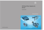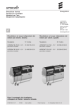
1
AIRTRONIC D2 / AIRTRONIC D4
Troubleshooting and repair instructions
Eberspächer ®
J. Eberspächer
GmbH & Co.
Eberspächerstr. 24
D -73730 Esslingen
Telefon (zentral)
(07 11) 9 39 - 00
Telefax
(07 11) 9 39 - 05 00
www.eberspaecher.com
Valid for the following heater versions:
AIRTRONIC D2
AIRTRONIC D4
25 2069 05 00 00 - 12 volt
25 2115 05 00 00 - 12 volt (complete package)
25 2113 05 00 00 - 12 volt
25 2070 05 00 00 - 24 volt
25 2116 05 00 00 - 24 volt (complete package)
25 2114 05 00 00 - 24 volt
25 2069 95 13 30
09.2001
Subject to change
Printed in Germany
1
© J. Eberspächer GmbH & Co.
Contents
Page
Important information prior to any work
Areas of use of the AIRTRONIC ........................................ 2
Content and purpose
These instructions serve to eliminate any malfunctions and
to carry out repairs on the AIRTRONIC. Any work necessary
for this may only be carried out by appropriately trained staff
at an Eberspächer service partner.
Statutory regulations and safety instructions
for the installation and repair of the AIRTRONIC ............. 3
Sectional drawing ............................................................. 4
Function ............................................................................ 5
- Switching on / off the AIRTRONIC
- Start the AIRTRONIC
- Temperature selection with the control element
- Control in heating mode
- Fan mode
- Model GGVS / TRS 003 / ADR / ADR 99
- Heating operation at high altitudes
Further documentation of the AIRTRONIC
These instructions contain all the necessary information and
instructions to repair the AIRTRONIC. If a spare part is
required as a result of a repair, this part must be ordered from
the spare parts list. If necessary, the technical description /
installation and operating instructions may be used.
Prevention of accidents and important information
The general accident prevention regulations and relevant
operational safety instructions always have to be complied
with. For further information, please refer to page 3.
Controls and safety devices ............................................. 6
Forced cut-off in GGVS / TRS 003 / ADR / ADR 99 mode .. 6
Environmental protection
Eberspächer is accepting the challenge and actively
participates in avoiding and removing any ecological
problems. Our course of manufacture has been certified in
accordance with ISO 9000 (quality management) and with
ISO 14001 (environmental management). In addition to ISO
9000, Eberspächer has also been certified in accordance
with QS 9000 (extended quality management of the
American motor car industry of the manufacturers Ford, GM
and Chrysler) as well as in accordance with VDA 6.1
(extended quality management of the German motor car
industry).
In the event of a malfunction,
check the following points ................................................. 6
Diagnosis with integrated module clock .......................... 6
Checking the control unit (rotary potentiometer) ............. 6
Function diagram .............................................................. 7
Technical data .................................................................. 8
Control values ................................................................... 9
Fault diagnosis with the module clock ............................ 10
Testing the operator control unit ...................................... 11
Disposal
Disposal of materials:
Old devices, defect components and packaging material
must all be subjected to pure-grade sorting so that all parts
can be disposed of in an environment-friendly manner or,
where possible, recycled. Electric motors, controllers and
sensors (e.g. temperature sensors) are to be considered as
“electronic scrap”.
Dismantling the heater:
The heater is dismantled in accordance with the repair steps
described in these instructions.
Packaging:
The heater packaging can be kept for possible return.
Fault codes / Description of fault ............................. 12 – 15
Circuit diagram AIRTRONIC D2 / D4 ........................ 16, 17
Circuit diagram control elements – part 1 ....................... 18
Circuit diagram control elements – part 2 ....................... 19
Circuit diagram AIRTRONIC D2 / D4 –
GGVS / TRS 003 / ADR / ADR 99 ................................ 20, 21
Circuit diagram control elements –
GGVS / TRS 003 / ADR / ADR 99 ................................ 22, 23
Repair instructions ................................................... 24 – 31
Measuring the fuel quantity ............................................. 32
Area of use of the AIRTRONIC
Taking into consideration their heating capacity, the stationary
and auxiliary heaters ‘AIRTRONIC’ are intended for installation
and use in all types of motor vehicles and their trailers, in
construction machines, machines used in agriculture, in boats,
ships and yachts for the purpose of preheating, clearing of
window panes, heating and keeping warm of driver’s or
working cabs, cargo compartments, ship’s cabins, passenger
or crew transport spaces, engine motors and aggregates.
The AIRTRONIC is suitable for use and permitted to be installed
in vehicle spaces used by passengers and to be installed into
vehicles used to transport dangerous substances corresponding to the regulations in accordance with GGVS / TRS 003 /
ADR / ADR 99 (detailed information in this regard is contained
in an information sheet with the print No. 25 2069 95 13 50).
When installing the device for the purpose of cargo compartment / cargo heating, the standard AIRTRONIC controller has
to be exchanged against the corresponding TRS 003 controller
(see heater price list or spare part list).
However, it is not permitted to be installed in the driver’s cab
or passenger compartment of coaches with more than
9 seats.
The ‘statutory regulations’, ‘safety instructions’ and ‘important
instructions’ relevant to the installation and printed below in
these troubleshooting and repair instructions, and which
govern the equipment selection, area of use, installation and
operation of the AIRTRONIC must be taken into consideration.
Based on its functional purpose, the AIRTRONIC is not
permitted to be used for other areas of use apart from those
listed, in particular not for a long-term continuous operation,
e.g. to preheat and heat living spaces, garages, working huts,
week-end homes, hunting lodges, houseboats or similar as
well as not to heat up or to dry objects or living beings (man or
beast) by directly blowing hot air onto them and / or blowing
hot air into appropriate receptacles.
2
§
Statutory regulations for the installation
and repair of the AIRTRONIC
!
• For installation in motor vehicles subject to the
Regulations authorizing the Use of Vehicles for Road
Traffic (StVZO), the air heater has been approved by the
German Federal Office for Motor Traffic in keeping with
the ‘General Design Certification’ (AGB) and the official
test symbol is marked on the type plate of the heater.
AIRTRONIC D2
AIRTRONIC D4
Safety instructions concerning the
installation and repair of the AIRTRONIC
Danger of burns and injury!
Before commencing any work on the AIRTRONIC,
disconnect the vehicle battery.
The AIRTRONIC may only be started up if the top shell and
the exhaust hood have been mounted in accordance with
the regulations and if the air duct on the suction and
heating air side has been carried out in accordance with
the regulations.
S 318
S 323
• The mounting requirements associated with the
General Design Certification (AGB) and further statutory
regulations have been printed in the corresponding
sections of these mounting instructions.
• When the air heater is installed in special vehicles, the
regulations governing such vehicles must be taken into
account (e.g. GGVS / TRS 003 / ADR / ADR 99 for
vehicles used to transport dangerous substances).
• The year in which the air heater was operated for the
first time must be permanently recorded on the type
plate. To this end, 3 different years have been printed
on the corresponding field of the type plate. The valid
year is to be identified by removing (detaching) those
two years which are not applicable.
• Subsequent installation of the heater must be carried
out in conformity with these mounting instructions and
must be examined and certified in writing by an officially
approved vehicle specialist or inspector or employee
(Section 4 of Annex VIII b to the StVZO) in conformity
with § 19 Section 3 StVZO. The effectiveness of the
design certification (ABG) for the heater is dependent
on this.
At the discretion of the vehicle owner, the certificate
can be issued as follows:
– As separate ‘Certificate of Approval’ which must
always be kept in the vehicle. A blank form for this
‘Certificate of Approval’ is attached at the end of the
operating instructions for the heater.
Neutral certificates of approval available to the motor
vehicle specialist are also permissible.
In both cases, the vehicle manufacturer, vehicle
model and vehicle identification number must be
entered.
– As entry in the vehicle registration document
(assessing authority) and in the vehicle identification
card (licencing authority.)
• For vehicles not subject to the StVZO (e.g. ships), it is
necessary to observe the specific regulations and
mounting instructions applicable to the given vehicle;
these may difffer regionally.
• The heater may only be installed or repaired – in case
of the heater being handed in for repair or guarantee
reasons - by a specialist workshop approved by the
manufacturer (service partner) in keeping with these
mounting instructions and possible special installation
recom-mendations.
• The information sticker ‘Switch off heater before
refuelling’ suppplied with the heater must be attached
in a suitable position on the vehicle (close to the fuel
filler neck).
During operation, the top shell may not be opened and hot
parts not be touched.
ATTENTION!
Important instructions for
the installation and repair
of the AIRTRONIC
When mounting or repairing the heater, only original
accessories and original spare parts may be used.
Changes to the AIRTRONIC or to components relevant to
the heating, the use of outside parts not approved by
Eberspächer as well as an installation or operation
differing from the statutory, safety and / or function relevant specifications contained in the mounting instructions
and in the operating instructions are not permissible:
this applies in particular to the electric wiring (circuit
diagrams), the fuel supply, the combustion air and
exhaust gas duct.
Only the control elements provided and / or approved by
us, either on their own or in a given combination, may be
used to operate the AIRTRONIC. The use of other control
elements may lead to malfunctions of the heater / heating
operation.
Non-compliance with the statutory, safety and / or
function relevant specifications may lead to the lapse of
the General Design Certification (ABG) of the AIRTRONIC
and to the exclusion of guarantee and liability on the part
of the company J. Eberspächer GmbH & Co.
Please note!
Further ‘Safety instructions concerning the installation
and repair of the AIRTRONIC’ as well as ‘Important
instructions concerning the installation’ have been
printed directly in the corresponding sections of these
troubleshooting and repair instructions.
3
Sectional drawing
1
2
3
4
5
6
7
8
9
10
11
12
13
14
15
Hot-air impeller
Control unit
Combustion air impeller
Glow plug
Cover
Heat exchanger
Combi-sensor
(overheating sensor / flame sensor)
Module clock
Change-over switch ‘heating / ventilating’
Fuse carrier with master fuse and fuse ‘actuation’
Electric motor
Fuel connection
Flange seal
Combustion chamber
Exhaust hood
AIRTRONIC D2 = Ø 60 mm or Ø 75 mm
AIRTRONIC D4 = Ø 75 mm or Ø 90 mm
Combustion air hose
Dosing pump
Cup sieve built into the dosing pump
Exhaust
Flexible exhaust gas pipe
Exhaust silencer
16
17
18
19
20
21
F
W
A
B
V
4
=
=
=
=
=
fresh air
hot air
exhaust gas
fuel
combustion air function
Function
fan will continue to run for approx. 4 minutes to allow the
heater to cool down.
Afterwards the fan will continue to run at the slowest
speed (recirculation mode) or will be switched off (fresh
air mode) until a renewed start of the heater.
Initial start-up
If the AIRTRONIC has been properly installed in
accordance with the installation instructions and if the
fuel supply system has been carefully deaerated, the
initial start-up may commence.
Switch on the AIRTRONIC at the control element. During
the trial run of the AIRTRONIC, all connections and the
entire heating system have to be checked for air-tightness
and tight fit.
Should the AIRTRONIC indicate a malfunction, trouble
shooting as described on page 6 must be carried out.
Fan mode
To start the AIRTRONIC in fan mode, the change-over
switch ‘heating / ventilating’ needs to be actuated first
before the heater is switched on.
Switching off
As soon as the AIRTRONIC is switched off, the pilot lamps
go out and fuel pumping is switched off. The fan will
continue to run for approx. 4 minutes to cool down the
heater.
For cleaning, the glow plug is switched off for 40 seconds
(AIRTRONIC D2) and 30 seconds (AIRTRONIC D4) while
the fan is still running.
Special case:
If no fuel has been delivered until switch-off, or if the
AIRTRONIC is set to the ‘OFF’ control level, then the
AIRTRONIC is stopped without the fan continuing to run.
Switching on
The pilot lamp in the control element lights up when the
heater is switched on.
The glow plug is switched on and the fan will start running
at a low speed.
Please note!
If there is still too much residual heat in the heat
exchanger from a previous heating operation, first only
the fan (cold blowing) will run.
The heater will only start once all the residual heat has
been dissipated.
Start
AIRTRONIC D2
Fuel starts to be delivered after approx. 60 seconds. The
fuel-air mixture in the combustion chamber ignites. Once
the combi-sensor (flame sensor) has detected the flame,
the glow plug is switched off after 60 seconds.
After another 120 seconds, the AIRTRONIC has reached
the control stage “POWER” (maximum fuel quantity and
maximum fan speed).
Model GGVS / TRS 003 / ADR / ADR 99
The AIRTRONIC is GGVS / TRS 003 / ADR / ADR 99
suitable.
If, in conformity with StVZO (D), the AIRTRONIC is to be
built into road tankers used to transport dangerous
substances for the purpose of heating the driver’s cab,
the GGVS / TRS 003 / ADR / ADR 99 regulations have to
be complied with. (More detailed information regarding
the GGVS / TRS 003 / ADR / ADR 99 regulations can be
found in the information sheet with the print
No. 25 2069 95 13 50).
When installing the device for the purpose of cargo
compartment / cargo heating, the standard AIRTRONIC
controller has to be exchanged against the corresponding
TRS 003 controller (see heater price list or spare
part list).
For the wiring, refer to the circuit diagram on
pages 20 – 23.
AIRTRONIC D4
Fuel starts to be delivered after approx. 60 seconds. The
fuel-air mixture in the combustion chamber ignites. Once
the combi-sensor (flame sensor) has detected the flame,
the glow plug is switched off after 80 seconds.
The AIRTRONIC is in the control mode.
Temperature selection with the control element
The desired indoor temperature is preselected with the
rotary control switch. Depending on the heater selected,
on the size of the room to be heated and on the prevailing
outdoor temperature, this value may range between
+10 °C and +30 °C. The control switch setting to be
selected is an experimental value.
Heating operation at high altitudes
• Up to 1500 m:
Unrestricted heating operation is possible.
• Above 1500 m:
Heating operation is in principle possible for short
periods, e.g. when crossing a mountain pass or during
a brief stop.
In case of extended stays (e.g. winter camping), the fuel
supply has to be adapted to high altitude conditions.
Please consult the responsible regional sales agency.
Control in heating mode
In heating mode, the room temperature and the
temperature of the heating air taken in is continuously
measured.
Control commences if the temperature exceeds the
temperature preselected on the control element.
4 control levels have been provided for so that the heat
flow supplied by the heater can be accurately adapted to
the heating requirements. Each control setting has its own
fan speed and fuel quantity. If the adjusted temperature is
even exceeded at the lowest control level, then the
AIRTRONIC is adjusted to the ‘OFF’ control level and the
5
Control and safety devices
In the event of a malfunction, check the following points
• If the AIRTRONIC does not ignite within 90 seconds after
fuel pumping has started, then the start is repeated in the
manner described.
A malfunction cut-off is effected if after a further
90 seconds of fuel pumping the AIRTRONIC once again
fails to ignite, i.e. fuel pump switches off and the
ventilator continues to run for approx. 4 minutes.
If the AIRTRONIC does not start when it is switched on:
• Switch off the AIRTRONIC and then switch it back on
again, but no more than twice in succession.
If the AIRTRONIC still does not start, then check:
• Is there fuel in the tank?
• If the flame extinguishes by itself during operation,
a renewed start is carried out first. If the AIRTRONIC fails
to ignite within 90 seconds after fuel pumping has
started again or if it does ignite but then extinguishes
itself within the next 15 minutes, a malfunction cut-off is
effected, i.e. fuel pump switches off and the ventilator
continues to run for approx. 4 minutes.
It is possible to override a malfunction cut-off by briefly
switching the heater off and on again.
Do not repeat this more than twice in succession!
• Have any fuses blown?
AIRTRONIC 12 V – main fuse 20 A
AIRTRONIC 24 V – main fuse 10 A
AIRTRONIC 12 / 24 V – fuse, actuation 5 A
• Are all electric wires and connections ok?
• Are the heating-air duct, combustion-air duct
or the exhaust-gas duct blocked?
• If the AIRTRONIC unintentionally remains in ‘ventilating’
mode after it is switched on, the control element has to
be checked for a short circuit – compare fault
description of fault code 063 in this regard. If this fault
occurs, no fault code will be displayed.
• In the case of overheating, the combi-sensor will
respond, the fuel supply will be interrupted and
a malfunction cut-off will be effected.
Once the cause of overheating has been eliminated, the
AIRTRONIC can be restarted by briefly switching it off
and on again.
If these points are OK, then proceed with a diagnosis test
using the JE diagnosis unit or the module clock, and
check the control unit with the corresponding testing
instrument.
• If the upper or lower voltage limit is reached,
a malfunction cut-off is effected after 20 seconds.
• The AIRTRONIC will not start if the glow plug or ventilator
motor is defective or if the electrical line
to the dosing pump is interrupted.
Diagnosis with integrated module clock
• In the case of defective combi-sensor or interrupted
electric lead, the AIRTRONIC does not start and the
malfunction shutdown then takes place.
Proceed with fault diagnosis with the module clock,
see page 10.
• The speed of the fan motor is continuously monitored.
If the fan motor does not start or if the speed deviates
by more than 10%, a malfunction cut-off is effected after
30 seconds.
Diagnosis test with the JE diagnosis unit and additional
adapter cable
Order no. diagnosis unit
22 1512 89 00 00
Order no. adapter cable
22 1000 31 86 00
• When switching off the AIRTRONIC, the glow plug is
switched on for 40 seconds, while the fan motor is
running, (afterglowing) to clean it of any combustion
residues.
Connection: see installation instructions included with
the adapter cable.
Instructions: see oeprating instructions included with the
diagnosis unit.
Forced cut-off in GGVS / TRS 003 / ADR / ADR 99 mode
Checking the control unit (rotary potentiometer)
Order no. test unit 22 1509 89 00 00
If it has been installed in vehicles used to transport
dangerous substances (e.g. road tankers), the AIRTRONIC
must be switched off before any hazardous area (refinery,
petrol station, etc.) is entered. If this is not complied with,
the AIRTRONIC will automatically shut down if:
• The vehicle’s engine is turned off.
• An accessory unit is switched on
(e.g. auxiliary drive for the unloading pump).
After cut-off, the fan will briefly continue to run
for max. 40 seconds.
Connection and control of the test unit see page 11.
6
Functional diagram AIRTRONIC D2
Functional diagram AIRTRONIC D4
7
Technical data
Heater
AIRTRONIC D2
AIRTRONIC D4
Heating medium
Air
Heat flow settings
Step
Step
Power
Fast
Medium
Slow
Power
Fast
Medium
Slow
Heat flow (watt)
2200
1800
1200
850
4000
3000
2000
1000
Hot-air throughput without counterpressure (kg/h)
105
87
60
42
185
150
110
65
Fuel consumption (l/h)
0.28
0.23
0.15
0.10
0.51
0.38
0.25
0.13
34
23
12
8
40
24
13
7
Electrical input (watt)
During operation
12 V and 24 V
When starting
12 V and 24 V
During control pause "OFF"
<
_ 100
<_ 100
4 to 5
4 to 5
Rated voltage
12 V or 24 V
Operating range
Lower voltage limit
An under-voltage protecting device
in the controller turns off the heater
at approx. 10.5 V and 21 V
10.5 V and 21 V
Response time – under-voltage protection: 20 seconds
Upper voltage limit
An over-voltage protecting device
in the controller turns off the heater
at approx. 15 V and 28 V
16 V and 32 V
Response time – over-voltage protection: 20 seconds
Fuel
For "Fuel quality"
and "Fuel at low temperatures"
see Operating Instructions (page 13)
Commercial diesel fuel
(acc. to DIN EN 590)
Permissible ambient temperature
Operation
–40 °C to +70 °C
Storage
–40 °C to +85 °C
Degree of radio interference suppression
3 for UKW, 4 for KW, 5 for MW / LW
Maximum air-intake temperature
Weight
+40 °C
approx. 2.7 kg
approx. 4.5 kg
All technical data ± 10 %
Noise emission inside the vehicle
ATTENTION!
Technical data specified have to be complied with in so
far as this can be influenced and the minimum / maximum
values may not be exceeded or fallen short of as this may
lead to malfunctions of the AIRTRONIC and / or of the
heating operation and / or to damage to components
relevant to the heating.
The highest sound pressure level is < 56 dB (A), measured
in the operating setting “Fast”, inconformity with 3. GSGV
and DIN 45 635 – Part 1.
8
Control values
Motor speed
Control stage
• Power
• Fast
• Medium
• Slow
• Adjustment
– in circulation mode with temperature sensor, internal
– in fresh air mode with temperature sensor, external
• Ventilation
AIRTRONIC D2
4800 U/min ± 140 U/min
4000 U/min ± 120 U/min
2800 U/min ± 80 U/min
2000 U/min ± 60 U/min
AIRTRONIC D4
4400 U/min ± 130 U/min
3600 U/min ± 100 U/min
2800 U/min ± 80 U/min
1600 U/min ± 50 U/min
600 U/min ± 20 U/min
0 U/min
4800 U/min ± 140 U/min
600 U/min ± 20 U/min
0 U/min
3600 U/min ± 100 U/min
Resistance values
Component
Blower motor
AIRTRONIC D2 - 12 V
0,6 W ± 0,1 W
AIRTRONIC D2 - 24 V
2 W ± 0,4 W
AIRTRONIC D4 - 12 V
0,4 W ± 0,1 W
AIRTRONIC D4 - 24 V
1,5 W ± 0,3 W
Glow plug
0,5 W ± 0,05 W
2 W ± 0,2 W
0,5 W ± 0,05 W
2 W ± 0,2 W
Dosing pump
10 W ± 0,5 W
36 W ± 1,8 W
10 W ± 0,5 W
36 W ± 1,8 W
Operator control unit
set value potentiometer
1750 – 2080 W ± 80 W
Switching value
Component
Overheating sensor
AIRTRONIC D2 / D4
160 °C – 170 °C
measured in the control stage "power"
and at a clearance of 300 mm
from the hot air outlet
Exhaust value
CO2 in exhaust in control stage "fast"
AIRTRONIC D2 / D4
7.5 – 12.5 Vol. %
Soot number as per Bacharach
<6
Temperature sensor, tested externally
Values table temperature sensor, external
Test the external temperature sensor with a digital
multimeter. If the resistance value is outside the set point
indicated in the values table, then replace the external
temperature sensor.
Temperature °C
0
5
10
15
20
25
30
35
40
45
2400
Resistance (Ohm)
2200
2000
1800
1600
1400
1200
1000
–40
–30
–20
–10
0
10
20
Temperature (°C)
30
40
50
9
Resistance W
min.
1600
1670
1745
1820
1895
1970
2050
2130
2210
2295
max.
1660
1730
1800
1870
1950
2030
2110
2190
2280
2370
Fault diagnosis with the module clock
If the controller has detected a fault when the heater is
turned on or during heater operation, then the module
clock will indicate the fault within 15 seconds as F with
a 2-digit number.
Example:
F 64 (= current fault)
and flashing heating symbol.
For fault code, description of faults and remedies, please
see pages 12 – 15.
1
2
3
Timer
Preselection
Heating
4
5
6
Backwards
Forwards
Display with fault indication
Interrogating the fault memory in the controller
Deleting the fault memory
The electronic controller can store up to 5 faults which
can then be read-out and displayed on the module clock.
The current fault is moved to memory location F1.
Previous faults are moved down to the memory locations
F2 to F5.
Precondition:
There is an electrical connection from terminal 15
(ignition) to the module clock, 12-pin connector,
chamber 10.
Press the c key. The current fault F 15 or F 50 is
displayed. Then press the a key, hold it and press the p
key within 2 seconds.
The module clock is now in the program “interrogate fault
memory”.
Continue operation:
Turn off the ignition (terminal 15).
Press the a key and the p key at the same time, then turn
on the ignition (terminal 15) and wait until the following
appears on the display:
Interrogating the fault memory with module clock
Press the c key. The heater is turned on. Then press
the a key, hold it and press the p key within the next
two seconds. The current fault will then be displayed,
e.g. F : 64.
The stored faults (maximum 5 faults) can be called with
the e and F keys (max. 5 faults).
For fault code, description of faults and remedies, please
see pages 12 – 15.
Display after
ignition “ON”
Interrogating the fault memory with module clock,
for vehicles used to transport dangerous goods as
per GGVS / TRS 003 / ADR / ADR 99
The controller is unlocked after 3 seconds, then the
heater starts.
Display after heater
starts
Press the c key, the p key and the a key at the same
time, the AIRTRONIC can be switched on, the current fault
is indicated.
The stored faults (maximum 5 faults) can be called with
the e and F keys (max. 5 faults).
flashing display
heating symbol
does not flash
Display:
currently no fault,
heating symbol
Please note!
If the AIRTRONIC is not operated with the module clock,
then fault code interrogation is possible with a diagnosis
instrument and an additional adapter cable.
Order no. diagnosis instrument
Order no. adapter cable
22 1512 89 00 00
22 1000 31 86 00
Connection see installation instructions included with
the adapter cable.
Operation see operation instructions included with the
diagnosis instrument.
10
Testing the operator control unit
Order no. for the testing instrument –
operator control unit
22 1509 89 00 00
Before testing
Connect the right operating voltage (12 or 24 volt) to the
testing instrument with plus connected to the red socket
and minus to the blue socket.
• Disconnect the connector from the operator control
unit.
• Connect the cable from the testing instrument to the
operator control unit.
• Set the rotary knob on the operator control unit to
“heating”, the corresponding red LED on the testing
instrument must light up.
• Set the operator control unit to “0”, then press the “LED
red” button, the red control lamp on the operator control
unit must light up.
• Set the operator control unit to “heating”, then press the
“LED green” button, the corresponding red control lamp
on the testing instrument and the green control lamp on
the operator control unit must both light up.
––– OFF
AUS
Heating
Important!
Pay attention to the right operating voltage, as otherwise
the connected components can be damaged.
Testing the set value potentiometer in the operator
control unit
Set the “temp.sensor / poti” in the testing unit to “poti” and
slowly turn the rotary knob on the operator control unit.
The green LED temp.sensor/poti must light up and remain
on. Replace the operator control unit if there is a fault.
11
Fault code / Description of fault
Comment
• Remedy
000 No fault
–––
004 Warning:
Short-circuit in controller, fresh-air outlet
• Disconnect connection S1/B1 at AIRTRONIC. At connector B1, PIN 16,
check the line through to the relay fresh air blower for short circuit
to chassis, if OK --> replace controller.
005 Warning:
Short-circuit in controller,
theft warning unit outlet
• Disconnect connection S1/B1 at AIRTRONIC. At connector B1, PIN 16,
check the line through to the relay isolating switch or theft warning unit
inlet for short circuit to chassis, if OK --> replace controller.
009 GGVS / TRS 003 / ADR / ADR 99
switch-off
GGVS / TRS 003 / ADR / ADR 99 switch-off due to signal change
from (+) to (–) at connector S1, PIN 13 (D+)
or plus signal at connector S1, PIN 14 (HA+).
010 Overvoltage switch-off
Overvoltage for min. 20 seconds without interruption at controller –
AIRTRONIC does not function.
• Disconnect connection S1/B1 at AIRTRONIC. Start vehicle motor, measure
voltage at connector B1 between PIN 1 (cable 2.5² red) and
PIN 10 (cable 2.5² brown).
AIRTRONIC 12 volt – voltage > 16 volt --> check dynamo controller
AIRTRONIC 24 volt – voltage > 32 volt --> check dynamo controller.
011 Undervoltage switch-off
Undervoltage for min. 20 seconds without interruption at controller –
AIRTRONIC does not function.
• Disconnect connection S1/B1 at AIRTRONIC. Start vehicle motor, measure
voltage at connector B1 between PIN 1 (cable 2.5² red) and
PIN 10 (cable 2.5² brown).
Measured value should not differ from battery voltage. When the voltage
drops, check the chassis connections and the plus support of the battery
for corrosion and the right contact.
012 Overheating at the overheating sensor
Overheating sensor has detected an excessive temperature.
• Check hot air lines for clogging --> eliminate blockage
• Sum of partial guide numbers of air conveying parts too large --> check air
line, re-route if necessary. For partial guide numbers see accessory parts
catalogue.
• Check overheating sensor, diagram and values table see page 28,
if OK, --> measure fuel quantity, see page 32.
013 Overheating at the flame sensor
Flame sensor reports an excessive temperature at heat exchanger.
• Check hot air lines for clogging --> eliminate blockage
• Sum of partial guide numbers of air conveying parts too large --> check air
line, re-route if necessary. For partial guide numbers see accessory parts
catalogue.
• Check flame sensor, if OK, --> check overheating sensor. If overheating
sensor defect, --> replace combi-sensor. If overheating sensor OK, -->
measure fuel quantity, see page 32. Diagram and values table for flame
sensor and overheating sensor see page 28.
014 Temperature difference between
flame sensor and overheating sensor
too large
Too great a temperature difference between flame sensor and overheating
sensor.
• Check hot air lines for clogging --> eliminate blockage.
• Sum of partial guide numbers of air conveying parts too large --> check air
line, re-route if necessary. For partial guide numbers see accessory parts
catalogue.
• Check flame sensor, if OK, --> check overheating sensor. If overheating
sensor defect, --> replace combi-sensor. If overheating sensor OK,
--> measure fuel quantity, see page 32. If fuel quantity OK, --> replace
controller. Diagram and values table for flame sensor and overheating
sensor see page 28.
12
Fault code / Description of fault
Comment
• Remedy
015 Operating blocked
Fault code 015 is shown when AIRTRONIC is switched on again after fault
code 017. The hardware limit value for the overheating sensor, has been
exceeded, --> the controller is locked.
• Replace controller
017 Overheating
The hardware limit value for the overheating sensor, has been exceeded,
because the controller has not detected fault code 012 or 013,
--> the control unit is locked.
If AIRTRONIC is switched on again, fault code 015 is displayed.
• Replace controller
020 Glow plug interrupted
• Check continuity of glow plug.
AIRTRONIC 12 volt – approx. 0.5 W ± 0.05 W
AIRTRONIC 24 volt – approx. 2 W ± 0.2 W
021 Glow plug output: short circuit,
overload or chassis short.
or
Caution!
For AIRTRONIC 12 volt, check functions
with max. 8 volt.
For AIRTRONIC 24 volt, check functions
with max. 18 volt.
If voltage values are exceeded,
the component is destroyed.
Check short-circuit resistance
of mains unit: min. 20 A.
• Check functions of glow plug in installed condition, to do so disconnect
connector from controller. Apply voltage of 8 V resp. 18 V ± 0.1 V
to glow plug and measure current intensity after 40 seconds.
Glow plug is OK for the following values:
glow plug 8 volt – current = 9 A + 1.5 A / – 1.2 A
glow plug 18 volt – current = 4 A ± 0.5 A
If the values differ, --> replace glow plug.
• If the values of the continuity test and function test are OK,
check glow plug cable harness for damage and continuity.
If OK, replace controller.
031 Blower motor interrupted
• Check blower motor cable harness for correct routing and damage,
if OK --> disconnect cable harness from control unit and check
for continuity, if OK, --> replace controller.
032 Blower motor, short circuit
• Check functions of blower motor, to do so, disconnect connector from
controller.
Apply voltage of 8 V or 18 V ± 0.1 V to blower motor and measure current
intensity after 40 seconds.
Current < 6.5 A – blower motor OK --> replace controller
Current > 6.5 A --> replace blower.
Caution!
For AIRTRONIC 12 volt, check functions
with max. 8 volt.
For AIRTRONIC 24 volt, check functions
with max. 18 volt.
If voltage values are exceeded,
the component is destroyed.
Check short-circuit resistance
of mains unit: min. 20 A.
033 Blower motor does not turn
Speed deviation > 10 % of set value longer than 30 seconds
(set value see page 9).
Measure the speed of the combustion air blower with no-contact speed
testing instrument.
• Speed too low:
Fan blocks – check blower runs freely, remove any foreign bodies,
if OK, --> check blower (see fault code 032).
• Speed too high:
Magnet missing in impeller --> replace blower.
• Speed sensor in controller defect --> replace controller.
13
Fault code / Description of fault
Comment
• Remedy
047 Dosing pump – short-circuit or overload
• Disconnect connector from dosing pump, if fault code 048 (interruption)
is displayed then the dosing pump is defect, --> replace dosing pump.
• If fault code 047 is still displayed, then disconnect connection S1/B1
at AIRTRONIC. At connector B1, PIN 5, check line 1² green/red through
to dosing pump for short circuit to chassis (PIN 10), if OK --> replace
controller.
048 Dosing pump interrupted
• Disconnect connector from dosing pump and measure resistance value
of dosing pump (values see page 9). If resistance values OK,
then reconnect cable harness to the dosing pump.
• Disconnect connection S1/B1 at the AIRTRONIC and measure the
resistance value between PIN 5 and PIN 10. If OK, --> replace controller.
050 Too many unsuccessful start attempts
(operation blocked)
Controller is locked after too many unsuccessful start attempts
(max. 255 start attempts).
• Unlock controller by deleting the fault memory with the module clock
or diagnosis instrument.
051 Flame detected when switched on
If the resistance value of the flame sensor is 1274 W after switching on
(> 70 °C), then the blower of the AIRTRONIC runs for approx. 15 minutes
to cool down. If resistance does not fall below the above value
within 15 minutes, this is followed by a fault shut-down.
• Check flame sensor, diagrams and values table see page 28,
if OK, --> replace controller.
052 Safety time exceeded
No flame detected during start phase.
• Check exhaust and combustion air lines
• Check fuel supply / measure fuel quantity, see page 32.
• Check glow plug (see fault code 020 and 021)
• Check flame sensor, diagram and values table see page 28,
if OK, --> replace control unit.
053
054
055
056
Flame aborted in
POWER stage
FAST stage
MEDIUM stage
SLOW stage
AIRTRONIC has ignited (flame detected) and reports aborted flame
in a power stage.
• Check exhaust and combustion air lines.
• Check fuel supply / measure fuel quantity, see page 32.
• Check flame sensor, diagram and values table see page 28,
if OK, --> replace control unit.
060 Interruption external temperature
sensor
• Disconnect connection S2/B2 of external temperature sensor and
measure resistance value at connector B2, diagram and values table
see page 9. If temperature sensor OK, re-connect connection S2/B2.
• Disconnect connection S1/B1 at AIRTRONIC.
In connector housing B1 measure resistance between PIN 6 and Pin 12.
If there is an interruption, the ohmic value between PIN 6 and PIN 12
> 7175 W. If the resistance value is o.k., then the controller is defective.
061 Short circuit – external temperature
sensor
• Disconnect connection S2/B2 of external temperature sensor.
If fault code 060 is displayed --> check external temperature sensor,
diagram and values table see page 9.
If temperature sensor OK, --> check connection lines 0.5 green
and 0.5 brown/white for short circuit, if OK, re-connect connection S2/B2.
• Disconnect connection S1/B1 at AIRTRONIC. In connector housing B1,
measure resistance value between PIN 6 and PIN 12.
If there is a short circuit, the ohmic value between PIN 6 and PIN 12
< 486 W. If fault 061 continues to be displayed, the controller is defective.
14
Fault code / Description of fault
Comment
• Remedy
062 Operator control unit interrupted
• Disconnect connector from operator control unit and measure resistance
value of set value poti. Connection pins see page 16 to 23.
If the resistance value is OK, then reconnect connector to operator
control unit.
• Disconnect connection S1/B1 at AIRTRONIC. In connector housing B1,
measure resistance value between PIN 6 and PIN 7.
If resistance value OK, --> replace controller.
Resistance value for interruption between PIN 6 and PIN 7 > 7175 W.
Normal value: 1740 W – 2180 W (± 80 W).
063 Operator control unit short-circuit
• If a ‘ventilating’ switch has been built in, disconnect and check function.
If not o.k. --> replace switch.
• Disconnect connector from operator control unit.
If fault code 062 is displayed, replace operator control unit.
If operator control unit OK, check connection lines 0.5 green/red
and 0.5 brown/white for short-circuit.
If OK, --> reconnect connector to operator control unit.
• Disconnect connection S1/B1 at AIRTRONIC.
If fault 063 is still displayed, --> replace controller.
Resistance value for short circuit between PIN 6 and PIN 7 < 486 W.
Normal value: 1740 W – 2180 W (± 80 W).
Fault recognition only works in
heating mode. However, if a short
circuit already exists and the
AIRTRONIC is subsequently
switched on, ‘ventilating’ mode will
be active (no fault code).
064 Flame sensor interrupted
• Remove controller and disconnect green connector from controller.
Check flame sensor, diagram and values table see page 28.
If flame sensor OK, --> replace controller.
Resistance value for interruption > 7175 W.
065 Flame sensor short circuit
• Remove controller and disconnect green connector from controller.
If fault 064 is displayed, --> replace combi-sensor.
If fault 065 is still displayed, --> replace control unit.
Resistance value for short circuit < 486 W, see also diagram page 28.
071 Overheating sensor interrupted
• Remove controller, disconnect blue and green connectors from controller.
Measure resistance value at blue connector PIN 1 (cable 0.5² blue)
and at green connector PIN 2 (cable 0.5² brown/white).
If OK, --> replace controller.
Resistance value for interruption > 223 kW, see also diagram page 28.
072 Overheating sensor – short circuit
• Remove controller, disconnect blue connector from control unit.
If fault 071 displayed, --> replace combi-sensor.
If fault 072 is still displayed, --> replace controller.
Resistance value for short circuit < 183 W, see also diagram page 28.
090 Controller defect (internal fault)
Replace controller.
091 External fault voltage
Fault in controller caused by fault voltages from vehicle power supply.
Possible causes: Poor battery, battery charger --> eliminate fault voltage.
092 Controller defect (ROM fault)
Replace controller.
094 Controller defect (EEPROM fault)
Replace controller.
096 Internal temperature sensor defect
Replace controller or use external temperature sensor.
097 Controller defect
Replace controller.
15
Circuit diagram – AIRTRONIC D2 / AIRTRONIC D4
25 2069 00 98 01 0A
16
Parts list
1.1
Burner motor
1.2
Glow plug
1.5
Overheating sensor and flame sensor
2.1
Controller
2.2
Dosing pump
2.7
Main fuse
12 volt = 20 A; 24 volt = 10 A
2.7.1 Fuse, actuation 5 A
5.1
Battery
a)
Connect the control elements and external temperature
sensors according to the “Control Elements”
circuit diagram
• rt
Supply plus terminal 30
• ge Switch-on signal S+
• gr Temperature – actual value
• wsrt Switch off theft warning system
• br Supply minus terminal 31
• blws Diagnosis
• grrt Temperature – target value
• brws Connection to earth for external temperature
sensor and temperature target value
b)
Optional
• Fresh-air blower
and / or
• separate fresh air fan
Cable ends that are not being used must be isolated.
Plug and socket case are shown from the cable entry side.
Cable colours
sw
ws
rt
ge
gn
vi
br
gr
bl
li
=
=
=
=
=
=
=
=
=
=
black
white
red
yellow
green
violet
brown
grey
blew
purple
17
Circuit diagram, control elements – part 1
Cable colours
sw= black
ws= white
rt = red
ge = yellow
gn = green
vi = violet
br = brown
gr = grey
bl = blew
li = purple
25 2069 00 97 01 B
Parts list
3.1.11 Operating unit
Cable ends that are not being used must be insulated.
a) Connection of control elements to
the AIRTRONIC
• rt
Supply plus terminal 30
• ge
Switch-on signal S+
• gr
Temperature – actual value
• wsrt Switch off theft warning system
• br
Supply minus terminal 31
• blws Diagnosis
• grrt Temperature – target value
• brws Sensor reference signal
Plug and socket case are shown from the cable entry
side.
k) When connecting an automatic switch or radio
receiver – cut open wire at this point
3.1.16 Momentary-contact switch
3.2.12 Timer (optional)
3.3.6 Radio receiver (optional)
18
Circuit diagram, control elements – part 2
Cable colours
sw= black
ws= white
rt = red
ge= yellow
gn= green
vi = violet
br = brown
gr = grey
bl = blew
li = purple
25 2069 00 97 01 B
Parts list
2.15.1
2.15.9
3.1.9
3.2.8
3.9.1
External temperature sensor, room
Temperature sensor, outside temperature
Change-over switch ‘heating / ventilating’
Module clock
Diagnosis unit, JE diagnosis
a)
Connect the control elements to the AIRTRONIC
• rt
Supply plus terminal 30
• ge
Switch-on signal S+
• gr
Temperature – actual value
• wsrt Switch off theft warning system
• br
Supply minus terminal 31
• blws Diagnosis
• grrt Temperature – target value
• brws Connection to earth for external temperature
sensor and temperature target value
b)
c)
d)
e)
g)
h)
j)
l)
Terminal 15 – necessary when connecting TP 4
Lighting terminal 58
Connection for diagnosis unit
Connection for external temperature sensor
Connection for external heater key c
Connection for TP4 remote control
Connection for outside temperature sensor
Connection change-over switch ‘heating /
ventilating’ (optional). How to start: operate
change-over switch ‘heating / ventilating’,
then switch on the AIRTRONIC.
Cable ends that are not being used must be insulated.
Plug and socket case are shown from the cable entry
side.
19
Circuit diagram – AIRTRONIC D2 / AIRTRONIC D4 – GGVS / TRS 003 / ADR / ADR 99
Cable colours
sw= black
ws= white
rt = red
ge= yellow
gn= green
vi = violet
br = brown
gr = grey
bl = blew
li = purple
25 2069 00 96 01 B
20
Parts list
1.1
Burner motor
1.2
Glow plug
1.5
Overheating sensor and flame sensor
2.1
Controller
2.2
Dosing pump
2.7
Main fuse
12 volt = 20 A; 24 volt = 10 A
2.7.1 Fuse, actuation 5 A
5.1
Battery
5.2.1 Battery operating switch d)
(operation e.g. controlled via ignition lock)
Emergency-shutdown function in the case
of GGVS / TRS 003 / ADR / ADR 99 – item 5.2.2 – 5.5
5.2.2 Battery separating switch d)
5.3
Accessory drive HA+
5.3.1 Switch auxiliary drive
5.5
Generator D+
a)
Connect the control elements and external temperature
sensors according to the “Control Elements”
circuit diagram
• rt
Supply plus terminal 30
• ge
Switch-on signal S+
• gr
Temperature – actual value
• wsrt Switch off theft warning system
Feedback to GGVS / TRS 003 / ADR / ADR 99 switch clock
• br
Supply minus terminal 31
• blws Diagnosis
• grrt Temperature – target value
• brws Sensor reference signal
b)
Optional
• Fresh-air blower
and / or
• Vehicle fan control
c)
Wiring if operated subject to GGVS / TRS 003 / ADR / ADR 99
(transporters carrying dangerous substances in the
utility vehicle sector, e.g. road tanker)
d)
If only one control element is used for items 5.2.1 and 5.2.2, it must be ensured that,
if the function ‘opening of battery separating switch’ is actuated (emergency shutdown-function
in the case of GGVS / TRS 003 / ADR / ADR 99 and similar), the switch always breaks contact without delay
(without consideration for the heater mode) and breaks all of the heater’s circuits from the battery.
Cable ends that are not being used must be isolated.
Plug and socket case are shown from the cable entry side.
21
Circuit diagram, control elements – GGVS / TRS 003 / ADR / ADR 99
22
Parts list
2.15.1 External temperature sensor, room temperature
3.1.11 Control unit, round
3.2.8 Module clock (GGVS / TRS 003 / ADR / ADR 99 – potentiometer)
3.9.1 Diagnosis, JE-diagnosis
a)
Connect the control elements to the AIRTRONIC
• rt
Supply plus terminal 30
• ge
Switch-on signal S+
• gr
Temperature – actual value
• wsrt Feedback to GGVS / TRS 003 / ADR / ADR 99 switch clock
Switch off theft warning system
• br
Supply minus terminal 31
• blws Diagnosis
• grrt Temperature – target value
• brws Connection to earth for external temperature
sensor and temperature target value
b)
c)
d)
e)
g)
Terminal 15
Lighting terminal 58
Connection for diagnosis unit
Connection for external temperature sensor
Connection for external heater key c
Cable ends that are not being used must be insulated.
Plug and socket case are shown from the cable entry side.
Cable colours
sw
ws
rt
ge
gn
vi
br
gr
bl
li
=
=
=
=
=
=
=
=
=
=
black
white
red
yellow
green
violet
brown
grey
blew
purple
23
Repair instructions
Page
Page
Assembly drawing AIRTRONIC D2 / D4 ................... 25
Installing the combi-sensor
(overheating sensor / flame sensor) ......................... 29
Removing cover from the AIRTRONIC ..................... 26
Dismantling the heat exchanger
Removing the combustion air blower ...................... 30
Removing the controller
Checking the controller ............................................ 26
Removing the combustion chamber ........................ 31
Removing the glow plug ........................................... 27
Checking the fuel supply .......................................... 32
Removing the lining .................................................. 27
Measuring the fuel quantity ...................................... 32
Removing the combi-sensor
(overheating sensor / flame sensor) ......................... 28
Checking the combi-sensor
(overheating sensor / flame sensor) ......................... 28
Please note during servicing!
Note on AMP unlocking tool:
During repair work, the AIRTRONIC must always be
disconnected from the power supply.
For this purpose, disconnect the connection S1 / B1 at the
AIRTRONIC.
The dealer addresses for the unlocking tools are available
directly from the manufacturer:
AMP Deutschland GmbH
Amperestrasse 7 – 11
63225 Langen bei Ffm.
Carefully check all seals and O-rings and replace where
necessary.
Phone: 06103 / 709 - 0
Fax: 06103 / 709 - 223
Clean all parts before reassembly and check for any signs
of damage, replace where necessary.
Note:
The repair instructions describe servicing the AIRTRONIC
in dismantled state.
The dismantling procedure is described in the
corresponding repair stages. Reassembly is carried out in
reverse order.
In exceptional cases corresponding reference is made in
the text.
24
Assembly drawing AIRTRONIC D2 / D4
Parts list
1
2
3
4
5
6
7
Combustion air blower
Seal – combustion air blower / heat exchanger
Combustion chamber
Seal – combustion chamber / heat exchanger
Heat exchanger
Controller
Combi-sensor (overheating sensor / flame sensor)
with mounting tool
8
9
10
11
12
13
25
Clip
Glow plug, with special tool (SW 12)
Lining – plug support with mounting tool
Cover
Outer case (lower part)
Flange seal
Removing the cover from the AIRTRONIC (see picture 1)
햲
1.
Unlock both seal plates, lift cover and take up to the front.
2.
Note:
The cover must always be removed from the AIRTRONIC
for all repair stages.
You may have to wait for the device to cool down.
햳
Cable harness exit out of the harness either left or right.
Fig. 1
햲
햳
Cover
Seal plates
Removing the controller (see fig. 2)
햳
• Remove the AIRTRONIC cover (see fig. 1).
햴
Unscrew fastening screw, press retaining brackets
together, lift out the controller. Unclip the lines from the
holder of the controller (observe the positions of the lines).
Withdraw the bushing (lower part) from the outer case.
Disconnect the controller from the controller. The
controller can now be removed.
Note:
When reassembling the controller, ensure that the lines
are correctly clipped in the holder of the controller, and
that the connectors are plugged into the controller (noninterchangeable).
햵
Tightening torque for the fastening screw no. 햲: 2 +0.2 Nm
Fig. 2
햲
햳
햴
햴
Fastening screw
Retaining brackets
Controller
Bushing
Checking the controller
A test instrument is necessary to check the controller in
dismantled state. The test instrument is connected up to
the PC and tests the controller with an installed test
programme.
Order no. – test instrument
------
ur
is c
t
n
me
ru
nst
st i tion
e
t
a
The repar
p
n
i
26
ren
tly
햲
Removing the glow plug
햳
햴
• Remove the AIRTRONIC cover (see fig. 1)
• Remove the controller (see fig. 2)
Disconnect the connector of the glow plug cable harness
from the controller.
Withdraw the rubber bush and use the special tool
(SW 12) to unscrew the glow plug.
The special tool is included with the glow plug.
Tightening torque of the glow plug: 6
+0.5
Nm
Special tool glow plug
Note:
When the glow plus has been removed, check the lining
of the support in installed state for any contamination.
The lining must be replaced of the surface is covered
with dirt.
햲
Fig. 3
햲
햳
햴
Glow plug
Connector of glow plug cable harness
Rubber bush
Removing the lining
Pull the lining out of the support with pointed pliers. Blow
out the support with compressed air.
If necessary, carefully pierce with a wire.
햲
The special tool has to be used to install the new lining.
The special tool is included with the lining. Push the lining
onto the special tool, watching the position of the recess.
The recess must be position at right angles (90°) to the
axis of the heater (see fig. 4).
햳
Push the tool with the lining carefully as far as it will go,
ensuring that the bore (Æ 2.7 mm) for the glow plug
ventilation is free (see drawing 1).
Fig. 4
햲
햳
Special tool with lining
Position of the recess
햲
햲
햳
햳
Lining
Bore (Ø 2.7 mm)
for glow plug ventilation
Drawing 1
27
Removing the combi-sensor (overheating sensor /
flame sensor)
• Remove the AIRTRONIC cover (see fig. 1)
• Remove the controller (see fig. 2)
햳
Disconnect both connectors of the cable harness “combisensor” from the controller.
Unlock clip from combi-sensor.
Remove combi-sensor.
햲
Fig. 5
햲
햳
Cable harness “combi-sensor”
Clip
Checking the combi-sensor
Observe a max. temperature of 320 °C for checking
the combi-sensor.
Overheating sensor
Flame sensor
Check the overheating sensor with a digital multimeter.
If the resistance value is outside the set point indicated in
the values table, then the combi-sensor must be replaced.
Check the flame sensor with a digital multimeter.
If the resistance value is outside the set point indicated in
the values table, then the combi-sensor must be replaced.
1800
2400
1600
2200
1200
2000
Resistance (Ohm)
Resistance (kOhm)
2000
1000
800
600
400
1800
1600
1400
1200
1000
200
800
–40
200
140
120
100
80
60
40
20
0
–20
–40
0
0
Temperature (°C)
Resistance kW min.
1597.00
458.80
154.70
59.30
25.02
11.56
5.782
3.095
1.757
1.050
0.6554
0.4253
0.2857
100
150
200
250
300
350
Temperature (°C)
Values table overheating sensor
Temperature °C
- 40
- 20
0
20
40
60
80
100
120
140
160
180
200
50
Values table flame sensor
max.
1913.00
533.40
175.50
65.84
28.04
13.16
6.678
3.623
2.081
1.256
0.792
0.5187
0.3513
Temperature °C
- 40
0
40
80
120
160
200
240
280
320
360
400
28
Resistance W min.
825.90
980.00
1132.30
1282.80
1431.50
1578.30
1723.40
1866.60
2008.10
2147.70
2285.50
2421.50
max.
859.60
1020.00
1178.50
1335.10
1489.90
1642.80
1793.70
1942.80
2090.00
2235.40
2378.80
2520.30
Installing the combi-sensor (overheating sensor / flame
sensor)
햳
For AIRTRONIC D2 (Assembly using purpose-made tool)
Mount the special tool on the combi-sensor.
Place the combi-sensor on the heat exchanger using the
special tool. The special tool slides on the heat
exchanger until the combi-sensor meets the collar
(installation site of the combi-sensor).
Lock the combi-sensor in place and remove the purposemade tool. It is then vital to check that the combi-sensor
sits flat on the heat exchanger. If necessary use a mirror
and lamp to aid correct assembly.
Route the cable harness “combi-sensor” along the clip,
through the clip eyelet to the controller and connect.
햲
Drawing 2
햲
햳
Special tool – only necessary for AIRTRONIC D2
Combi-sensor
For AIRTRONIC D4 (Assembly without using purposemade tool)
Place the combi-sensor on the heat exchanger, checking
that the combi-sensor sits flat on the heat exchanger.
Lock the clip of the combi-sensor and check again that
the combi-sensor sits flat on the heat exchanger.
Route the cable harness “combi-sensor” along the clip,
through the clip eyelet to the controller and connect.
햳
Wiring diagram combi-sensor (overheating sensor /
flame sensor)
햲
Connector
blew
Connector
green
Fig. 6
햲
햳
햲 NTC 50 KW = overheating sensor
햳 PT 1000 = flame sensor
Special tool – only necessary for AIRTRONIC D2
Combi-sensor
Drawing 3
햲
햴
햳
햳
Drawing 4
Fig. 7
햲
햳
햲
햳
햴
Clip
Combi-sensor
29
햲
Clip
Cable harness “combi-sensor”
Special tool – only necessary for AIRTRONIC D2
Dismantling the heat exchanger
Removing the combustion air blower
• Remove the AIRTRONIC cover (see fig. 1)
• Remove the controller (see fig. 2)
햳
햴
Remove the flange seal.
Take the AIRTRONIC out of the outer case (lower part).
Unscrew the 4 fastening screws from the combustion air
blower.
Remove the combustion air blower and the seal from the
heat exchanger.
햲
Important!
When reassembling the combustion air blower, a new
seal is always required.
햴
Tighten the 4 fastening screws of the combustion air
blower in the series shown in the drawing, with
a tightening torque of 4 +0.5 Nm.
Fig. 8
햲
햳
햴
Combustion air blower
Heat exchanger
Fastening screw
햶
햳
햵
햴
햲
Drawing 5
햲 – 햵 Tighten the fastening screws in this sequence
with a tightening torque of 4 +0.5 Nm
햶 Always replace the seal between combustion air blower
and heat exchanger
30
Removing the combustion chamber
햳
• Remove the cover from the AIRTRONIC (see fig. 1).
Remove flange seal.
Take AIRTRONIC out of the outer case (lower part).
• Remove controller (see fig. 2)
• Remove glow plug (see fig. 3)
• Remove combustion air blower (see fig. 8).
햲
Unscrew the fastening screws.
For AIRTRONIC D2 = 3 fastening screws
For AIRTRONIC D4 = 4 fastening screws.
Pull the combustion chamber out to the front and remove
the seal from the heat exchanger.
햴
Note!
When reassembling the combustion chamber, the seal,
which has been enclosed with the spare part, must
always be replaced.
Fig. 9
햲 Combustion chamber
햳 Heat exchanger
햴 Fastening screws
AIRTRONIC D2 = 3 fastening screws
AIRTRONIC D4 = 4 fastening screws
Tighten the fastening screws of the combustion chamber
with a torque of 5 +0.5 Nm.
Note:
If the heat exchanger is being replaced, the combi-sensor
(overheating sensor / flame sensor) must be dismantled
and mounted to the new heat exchanger (see page 28
and 29).
햴
햳
햲
햵
Drawing 6
햲 Combustion chamber
햳 Seal between combustion chamber and
heat exchanger – must always be replaced
햴 Heat exchanger
햵 Fastening screws
AIRTRONIC D2 = 3 fastening screws
AIRTRONIC D4 = 4 fastening screws
31
Checking the fuel supply
Before measuring the fuel quantity, check the following
points of the fuel supply:
•
•
•
•
•
Check the filter in the dosing pump
Check that the fuel lines have been correctly routed.
Check that the fuel lines do not leak
Check and tighten the hose connections
Does the fuel withdrawal comply with the data
in the technical description?
Measuring the fuel quantity
1. Preparation
Disconnect the fuel pipe from the AIRTRONIC and drain
into a measuring glass (size 25 ml).
Switch on the AIRTRONIC. Once the fuel is being pumped
evenly (starts approx. 60 seconds after switching on), the
fuel pipe is filled and vented. Switch off the AIRTRONIC
and drain the measuring glass.
2. Measurement
Switch on the AIRTRONIC
The fuel is pumped approx. 60 seconds after switching
on. Hold the measuring glass on a level with the glow plug
during measurement.
AIRTRONIC D2
After the fuel has been pumped for approx. 90 seconds
it is switched off automatically. Switch off the heater*!
Read out the quantity of fuel in the measuring glass.
Caution!
Set value:
For precise fuel measurement, min. 11 / 22 volt or
max. 13 / 26 volt should be present in the control unit
during measurement.
min. 3.7 ml
max. 4.3 ml
AIRTRONIC D4
After the fuel has been pumped for approx. 110 seconds
it is switched off automatically. Switch off the heater*!
Read out the quantity of fuel in the measuring glass.
Set value:
min. 5.4 ml
max. 6.3 ml
If the measured fuel quantity is outside the values stated
above then the dosing pump has to be replaced.
* Important, as otherwise pumping of fuel will resume after approx. 120 sec.
햵
햲
햴
햳
Drawing 7
햲 AIRTRONIC
햳 Dosing pump
햴 Measuring glass (size 25 cm³)
햵 Disconnect fuel pipe from the AIRTRONIC
and drain in a measuring glass
32