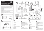
1
BLACK
DIC 2181s*
UCAB
Stereo Amplifier
Amplificateur Stéréo
© 2008
All rights reserved.
YAMAHA ELECTRONICS CORPORATION, USA 6660 ORANGETHORPE AVE., BUENA PARK, CALIF. 90620, U.S.A.
YAMAHA CANADA MUSIC LTD. 135 MILNER AVE., SCARBOROUGH, ONTARIO M1S 3R1, CANADA
YAMAHA ELECTRONIK EUROPA G.m.b.H. SIEMENSSTR. 22-34, 25462 RELLINGEN BEI HAMBURG, GERMANY
YAMAHA ELECTRONIQUE FRANCE S.A. RUE AMBROISE CROIZAT BP70 CROISSY-BEAUBOURG 77312 MARNE-LA-VALLEE CEDEX02, FRANCE
YAMAHA ELECTRONICS (UK) LTD. YAMAHA HOUSE, 200 RICKMANSWORTH ROAD WATFORD, HERTS WD18 7GQ, ENGLAND
YAMAHA SCANDINAVIA A.B. J A WETTERGRENS GATA 1, BOX 30053, 400 43 VÄSTRA FRÖLUNDA, SWEDEN
YAMAHA MUSIC AUSTRALIA PTY. LTD. LEVEL 1, 99 QUEENSBRIDGE STREET, SOUTHBANK, VIC 3006, AUSTRALIA
OWNER’S MANUAL
MODE D’EMPLOI
Printed in Malaysia
WN63040
HiFi Began with Yamaha
Yamaha’s involvement with and passion for music goes back
more than a century, to when we built our first reed organ in
1887. Now we are the world’s leading producer of pianos and
other musical instruments, and are involved with music in many
other ways as well. We manufacture professional recording
equipment, we design concert halls and we assist artists at
concerts with set up and sound tuning.
This knowledge and experience benefits our production of
audio components in many ways. We introduced our first HiFi
(High Fidelity) turntable in 1955. Thereafter we were one of the first
to offer mass-produced, high quality audio equipment,
and introduced many legendary stereo components.
We hope you enjoy the genuine HiFi experience of
Yamaha Natural Sound.
Excellence in Audio Achievement
1922: We introduced a high-quality handwound phonograph.
Since 1955, we have released many HiFi
components, including turntables, tuners,
integrated amplifiers, control amplifiers,
power amplifiers and speakers.
NS-20 Monitor Speaker
NS-20
CA-1000
NS-690
NS-1000M
B-1
C-2
PX-1
NS-10M
CA-1000 Integrated Amplifier
Featuring A-Class operation, the CA-1000 set
the standard for integrated amplifiers.
NS-690 Monitor Speaker
NS-1000M Monitor Speaker
A truly legendary speaker still revered by HiFi enthusiasts
B-1 Power Amplifier
An innovative power amp that used FETs in all stages
C-2 Control Amplifier
Received top prize at the Milan International Music
and HiFi Show.
NS-10M Studio Monitor Speaker
Became of the most popular studio monitors in the world.
A-1 Integrated Amplifier
PX-1 Turntable
Yamaha’s first linear tracking turntable
B-6 Power Amplifier
Pyramid-shaped power amplifier with X power supply and
X amplifier
GT-2000/L Turntable
Ultra-precise heavyweight player embodying GT concept
CD-1 CD Player
First CD Player introduced in 1983
B-2x Power Amplifier
B-6
GT-2000
MX-10000 Power Amplifier and
CX-10000 Control Amplifier
Amplifier that redefined the capabilities of separate
components
100th anniversary model
AX-2000 Integrated Amplifier
AX-2000
GT-CD1
Soavo-1
Soavo-2
High S/N ratio (128 dB), digital direct function equipped
GT-CD1 CD Player
Top-loading type player with integrated separate structure
MX-1 Power Amplifier and CX-1 Control
Amplifier
Soavo-1 and Soavo-2 Natural Sound
Speaker Systems
A-S2000 Stereo Amplifier and
CD-S2000 Super Audio CD Player
A-S1000 Stereo Amplifier and
CD-S1000 Super Audio CD Player
◆ Floating balanced circuit design
The perfectly symmetrical, fully new floating balanced power amplifier maximizes the performance of the analog
amplifier.
◆ Parallel volume and tone control
◆ Four independent high capacity power supplies
◆ Horizontally symmetrical structure
◆ Phono amplifier with fully discrete structure
◆ Newly developed heavyweight feet to suppress vibrations
■ Supplied accessories
Please check that you have received all of the following parts.
• Remote control
• Batteries (AA, R6, UM-3) (×2)
• Power cable
• Safety brochure
Contents
Controls and functions.......................................................................................................................................... 6
Connections.......................................................................................................................................................... 14
Specifications ....................................................................................................................................................... 20
Troubleshooting................................................................................................................................................... 24
■ About this manual
• y indicates a tip for your operation.
• This manual is printed prior to production. Design and specifications are subject to change in part as a result of improvements, etc. In
case of differences between the manual and the product, the product has priority.
• The color of images in this manual may vary from the original.
• Read the “Safety brochure” before using this unit.
4 En
Controls and functions
In this chapter, you will learn the controls and functions of A-S1000.
5 En
Controls and functions
■ Front panel (left side)
BASS
-
POWER
PHONES
ON
+
SPEAKERS
OFF
A
B
A+B
BI-WIRING
OFF
1
2
3
4
1 POWER
Press upward or downward to turn on or off this unit.
2 Remote control sensor
Receives signals from the remote control.
y
y
The POWER indicator above lights up when this unit is turned
on.
The remote control transmits a directional infrared beam. Be sure
to aim the remote control directly at the remote control sensor on
the front panel of this unit during operation.
Notes
• If the POWER indicator flashes when you turn on this unit,
disconnect the power cable and refer to the troubleshooting
section (page 24).
• When you turn on this unit, there will be a few second delay
before this unit can reproduce sound.
30
6 En
30
Within 6 m (20 ft)
INPUT
TREBLE
BALANCE
VOLUME
CD
LINE 1
TUNER
LINE 2
PHONO
MAIN DIRECT
-
+
L
R
AUDIO MUTE
3 PHONES jack
Outputs audio for private listening with headphones.
Note
When headphones are plugged in:
– Both speaker sets connected to the SPEAKERS L/R CH A
and B terminals are turned off.
– No signals are output at the PRE OUT jacks, while signals are
output at the REC jacks.
– You cannot select MAIN DIRECT as the input source.
– If headphones are plugged into the PHONES jack while
MAIN DIRECT is selected as the input source, no audio is
output at the PHONES jack. Use the headphones jack of the
preamplifier connected to the MAIN IN jacks.
4 SPEAKERS
Turns on or off the speaker set connected to the
SPEAKERS L/R CH A and/or B terminals on the rear
panel.
• Switch to the OFF position to turn off both speaker
sets.
• Switch to the A or B position to turn on the speaker set
connected to the SPEAKERS L/R CH A or B
terminals.
• Switch to the A+B BI-WIRING position to turn on
both speaker sets.
Caution
If you use two sets (A and B), the impedance of each speaker
must be 8 Ω or higher. When only using one set of speakers (A or
B), use speakers with an impedance of 4 Ω or higher.
English
7 En
Controls and functions
■ Front panel (right side)
BASS
-
POWER
PHONES
ON
+
SPEAKERS
OFF
A
B
A+B
BI-WIRING
OFF
5
5 BASS
Increases or decreases the low frequency response. The
center position produces a flat response.
Control range: –9 dB to +9 dB
6 TREBLE
Increases or decreases the high frequency response. The
center position produces a flat response.
Control range: –9 dB to +9 dB
y
When both the BASS and TREBLE controls are set to the center
position, audio signal bypasses the tone control circuitry.
Note
The BASS and TREBLE controls do not affect the signals input
at the MAIN IN jacks (INPUT selector: MAIN DIRECT) and
signals output at the REC OUT jacks.
8 En
7 BALANCE
Adjusts the audio output balance of the left and right
speakers to compensate for sound imbalances caused by
speaker locations or listening room conditions.
Note
The BALANCE control does not affect the signals input at the
MAIN IN jacks (INPUT selector: MAIN DIRECT) and signals
output at the REC OUT jacks.
INPUT
TREBLE
BALANCE
VOLUME
CD
TUNER
LINE 1
PHONO
LINE 2
MAIN DIRECT
-
+
L
R
AUDIO MUTE
6
7
8
9
0
8 INPUT selector
Selects the input source you want to listen to.
The audio signals of the selected input source are also
output at the REC jacks.
9 AUDIO MUTE
Press downward to reduce the current volume level by
approximately 20 dB. Press again to restore the audio
output to the previous volume level.
y
y
• The input source names correspond to the names of the
connection jacks on the rear panel.
• Switch to the MAIN DIRECT position to select the component
connected to the MAIN IN jacks. When MAIN DIRECT is
selected as the input source, no signals are output at the PRE
OUT, REC, and PHONES jacks.
• The input setting is retained for about 1 week after the power is
turned off.
• The AUDIO MUTE indicator lights up while the mute function
is on.
• You can also rotate VOLUME on the front panel or press
VOL +/– on the remote control to resume the audio output.
0 VOLUME
Controls the volume level. This does not affect the REC
level.
Note
Note
The audio signals are not output at the REC jacks while LINE2 is
selected as the input source.
The VOLUME control does not affect when you select MAIN
DIRECT as the input source. Adjust the volume level using the
volume control on the preamplifier connected to the MAIN IN
jacks.
English
9 En
Controls and functions
■ Rear panel
1
2
3
SPEAKERS R CH
A
LINE2
INPUT
CD
R
TUNER
LINE 1
PB
REC
L
L
R
B
PHONO
MM
MC
GND
9
See page 14 for connection information.
1 SPEAKERS L/R CH terminals
5 PRE OUT jacks
2 INPUT jacks
y
3 LINE2 jacks
4 MAIN IN jacks
Note
Adjust the volume level using the volume control on the
preamplifier connected to the MAIN IN jacks when you select
MAIN DIRECT as the input source.
10 En
• When you connect audio pin plugs to the PRE OUT jacks to
drive the speakers using an external amplifier, it is not
necessary to use the SPEAKERS L/R CH terminals.
• The signal output at the PRE OUT jacks are affected by the
BASS and TREBLE settings.
• The PRE OUT jacks output the same channel signal as the
SPEAKERS L/R CH terminals.
• When you use a subwoofer, connect it to the PRE OUT jacks
and speakers to the SPEAKERS L/R CH terminals.
4
5
1
6
7
VOLTAGE SELECTOR
SPEAKERS L CH
A
230240V
MAIN IN PRE OUT
AC IN
B
6 AC IN
Use this inlet to plug in the supplied power cable.
7 VOLTAGE SELECTOR
(Asia and General models only)
The VOLTAGE SELECTOR on the rear panel of this unit
must be set for your local main voltage BEFORE plugging
the power cable into the AC wall outlet. Improper setting
of the VOLTAGE SELECTOR may cause damage to this
unit and create a potential fire hazard.
Rotate the VOLTAGE SELECTOR clockwise or
counterclockwise to the correct position using a straight
slot screwdriver.
Voltages are as follows:
............................ AC 110/120/220/230–240 V, 50/60 Hz
8
8 Foot
If this unit is unstable, you can adjust the foot height by
rotating it.
9 PHONO
Selects the type of magnetic cartridge of the turntable
connected to the PHONO jacks on the rear panel.
• Set to the MM position when the connected turntable has a
moving magnet (MM) cartridge.
• Set to the MC position when the connected turntable has a
moving coil (MC) cartridge.
Note
When you replace the cartridge, be sure to turn off this unit.
English
11 En
Controls and functions
■ Remote control
4 Amplifier control buttons
1
INPUT
/
Selects the input source you want to listen to.
A/B/C/D/E
Notes
• When MAIN DIRECT is selected as the input source, no
signals are output at the PRE OUT and REC jacks.
• If headphones are plugged into the PHONES jack while MAIN
DIRECT is selected as the input source, no audio is output at
the PHONES jack.
2
PRESET
VOL +/–
Controls the volume level.
Note
3
The VOLUME control does not affect when you select MAIN
DIRECT as the input source. Adjust the volume level using the
volume control on the preamplifier connected to the MAIN IN
jacks.
MUTE
Reduces the current volume level by approximately 20
dB. Press again to restore the audio output to the previous
volume level.
VOL
4
INPUT
MUTE
INPUT
VOL
y
You can also press VOL +/– to resume the audio output.
■ Installing batteries in the remote control
1
3
1 Infrared signal transmitter
Outputs infrared control signals.
2
2 Yamaha tuner control buttons
Control functions of Yamaha tuner. Refer to the owner’s
manual of your tuner for details.
Note
1
Press the
part and slide the battery
compartment cover off.
2
Insert the two supplied batteries
(AA, R6, UM-3) according to the polarity
markings (+ and –) on the inside of the
battery compartment.
3
Slide the cover back until it snaps into place.
Not all Yamaha tuners can be controlled by this remote control.
3 Yamaha CD player control buttons
Control various functions of Yamaha CD player. Refer to
the owner’s manual of your CD player for details.
y
Press
once to pause and twice to stop playback.
Note
Not all Yamaha CD players can be controlled by this remote
control.
12 En
Connections
In this section, you will make connections between A-S1000, speakers,
and source components.
Connections
Speakers A
(R channel)
CD player
Tuner
+
-
SPEAKERS R CH
A
LINE2
INPUT
CD
R
TUNER
LINE 1
PB
REC
MAIN IN PRE OUT
L
L
R
B
PHONO
MM
MC
GND
+
Ground
Speakers B
(R channel)
Turntable
DVD player,
etc.
Caution
• If you use two sets (A and B), the impedance of each speaker
must be 8 Ω or higher. When only using one set of speakers (A
or B), use speakers with an impedance of 4 Ω or higher.
• Do not let the bare speaker wires touch each other or do not let
them touch any metal part of this unit. This could damage this
unit and/or the speakers.
14 En
• All connections must be correct: L (left) to L, R (right) to R,
“+” to “+”, and “–” to “–”. If the connections are faulty, no
sound will be heard from the speakers, and if the polarity of the
speaker connections is incorrect, the sound will be unnatural
and lack bass. Also, refer to the owner’s manual for each of
your components.
• Connect your turntable to the GND terminal to reduce noise in
the signal. However, you may hear less noise without the
connection to the GND terminal for some turntables.
Preamplifier,
AV receiver, etc.
External amplifier or
active subwoofer
Pre-out
Speakers A
(L channel)
-
+
SPEAKERS L CH
A
LINE2
INPUT
D
TUNER
LINE 1
PB
REC
MAIN IN PRE OUT
L
L
R
AC IN
B
NO
MM
MC
GND
–
Output
+
Input
Speakers B
(L channel)
CD recorder,
tape deck, etc.
Caution
Fig. 1
Fig. 2
+
+
L
L
–
–
–
English
–
R
R
+
+
• Because the power amplifier of A-S1000 is of the floating
balanced type, the following types of connections are not
possible:
– Connecting with the left channel “–” terminal and the right
channel “–” terminal as well as “+” terminals (Fig. 1).
– Deliberately connecting with the left/right channel “–”
terminals and metal part on the rear panel of this unit, as well
as accidentally touching them.
– Connecting with the left channel “–” terminal and the right
channel “–” terminal inverted (cross connection, Fig. 2).
• Do not connect your active subwoofer to the SPEAKERS L/R
CH terminal. Connect it to the PRE OUT jacks of this unit.
15 En
Connections
Caution
If you use two sets (A and B), the impedance of each speaker
must be 8 Ω or higher. When only using one set of speakers (A or
B), use speakers with an impedance of 4 Ω or higher.
■ Connecting the speakers
1
■ Connecting the speakers using the
banana plug
(Except for Europe models)
First, tighten the knob and then insert the banana
plug into the end of the corresponding terminal.
Remove approximately 10 mm (0.4 in) of
insulation from the end of each speaker
cable and twist the exposed wires of the
cable together to prevent short circuits.
Banana plug
10 mm (0.4 in)
■ Connecting the speakers using the
Y-shaped lug
2
Unscrew the knob and then insert the bare
wire into the hole.
1
Unscrew the knob and then sandwich the
Y-shaped lug between the ring part and base.
Y-shaped lug
Slide
3
Tighten the knob.
16 En
2
Tighten the knob.
■ Bi-wire connection
The bi-wire connection separates the woofer from the
combined midrange and tweeter section. A bi-wire
compatible speaker has four binding post terminals. These
two sets of terminals allow the speaker to be split into two
independent sections. With these connections, the mid and
high frequency drivers are connected to one set of
terminals and the low frequency driver to another set of
terminals.
SPEAKERS L CH
A
B
■ VOLTAGE SELECTOR
(Asia and General models only)
Caution
The VOLTAGE SELECTOR on the rear panel of this unit
must be set for your local voltage BEFORE plugging the
power cable into the AC wall outlet. Improper setting of
the VOLTAGE SELECTOR may cause damage to this
unit and create a potential fire hazard.
Rotate the VOLTAGE SELECTOR clockwise or
counterclockwise to the correct position using a straight
slot screwdriver.
Voltages are as follows:
........................ AC 110/120/220/230–240 V, 50/60 Hz
VOLTAGE SELECTOR
230240V
Voltage
indication
Caution
When making bi-wiring connections, use speakers with an
impedance of 4 Ω or higher.
Note
When making bi-wiring connections, remove the shorting bridges
or cables on the speaker.
y
■ Connecting the power cable
Connect the power cable into the AC IN inlet on the rear
panel when all connections are complete, and then plug in
the power cable to the AC wall outlet.
To use the bi-wire connections, switch the SPEAKERS selector
to the A+B BI-WIRING position.
English
17 En
Connections
■ A-S1000 input/output table
INPUT
selector
CD
PHONO
TUNER
LINE1
LINE2
MAIN
DIRECT
Note
SPEAKERS
CD
PHONO
TUNER
LINE1
LINE2 PB
MAIN IN
No signal is output while the SPEAKERS
selector is switched to the OFF position.
PHONES
(Headphones)
CD
PHONO
TUNER
LINE1
LINE2 PB
–
PRE OUT
CD
PHONO
TUNER
LINE1
LINE2 PB
–
LINE2 REC
CD
PHONO
TUNER
LINE1
–
–
Output jacks
No signal is output at the SPEAKERS
terminals and PRE OUT jacks while
headphones are connected to the
PHONES jack.
The shaded area indicates that the BASS, TREBLE, BALANCE, and VOLUME controls are ineffective.
18 En
Specifications
In this section, you will find technical specifications for A-S1000.
Specifications
POWER SECTION
CONTROL SECTION
• Minimum RMS Output Power
(8 Ω , 20 Hz to 20 kHz, 0.02% THD) ...................... 90 W + 90 W
(6 Ω , 20 Hz to 20 kHz, 0.02% THD) .................. 105 W + 105 W
(4 Ω , 20 Hz to 20 kHz, 0.02% THD) .................. 140 W + 140 W
• Input Sensitivity/Input Impedance
CD, etc. .................................................................. 150 mV/47 kΩ
MM ......................................................................... 2.5 mV/47 kΩ
MC ........................................................................... 100 µV/50 Ω
MAIN IN ...................................................................... 1 V/47 kΩ
• Dynamic Power (IHF) (8/6/4/2 Ω) ................... 105/135/190/220 W
• Maximum Output Power
(1 kHz, 0.7% THD, 4 Ω) [U.K. and Europe models only]
.......................................................................................... 160 W
• Maximum Useful Output Power (JEITA)
(1 kHz, 10% THD, 8/4 Ω)
[Asia, General, China and Korea models only] ....... 115/190 W
• Dynamic Headroom
8 Ω ..................................................................................... 0.67 dB
• IEC Output Power [U.K. and Europe models only]
(1 kHz, 0.02% THD, 8/4 Ω)............................................ 90/145 W
• Damping Factor
1 kHz, 8 Ω ................................................................................ 160
• Maximum Input Signal
CD, etc. ................................................................................. 2.8 V
PHONO MM (1 kHz) ........................................................ 120 mV
PHONO MC (1 kHz) ............................................................ 7 mV
• Frequency Response
CD, etc. (Flat Position, 5 Hz to 100 kHz) ...................... +0/−3 dB
CD, etc. (Flat Position, 20 Hz to 20 kHz) ................... +0/−0.3 dB
• RIAA Equalization Deviation
PHONO MM (20 Hz to 20 kHz) ...................................... ±0.5 dB
PHONO MC (20 Hz to 20 kHz) ....................................... ±0.5 dB
• Total Harmonic Distortion
CD, etc. to SP OUT
(20 Hz to 20 kHz, 90 W/8 Ω) ........................................... 0.015%
PHONO MM to REC
(20 Hz to 20 kHz, 2 V) ..................................................... 0.005%
PHONO MC to REC
(20 Hz to 20 kHz, 2 V) ....................................................... 0.05%
• Intermodulation Distortion
CD, etc. to SP OUT
(Rated output, 8 Ω) ............................................................0.02%
• Signal to Noise Ratio (IHF-A Network)
CD, etc. (150 mV, Input shorted) ..........................................98 dB
PHONO MM (5 mV, Input shorted) .....................................93 dB
PHONO MC (500 µV, Input shorted) ..................................85 dB
• Residual Noise (IHF-A Network) .......................................... 73 µV
20 En
• Output Level/Output Impedance
REC OUT ............................................................. 150 mV/1.5 kΩ
PRE OUT ..................................................................... 1 V/1.5 kΩ
• Headphone Rated Output
1 kHz, 32 Ω , 0.2% THD ................................................... 23 mW
• Channel Separation
CD, etc. (5.1 kΩ Terminated, 1 kHz/10 kHz) ................. 74/54 dB
PHONO MM (Input shorted, 1 kHz/10 kHz, Vol.:−30 dB)
....................................................................................... 90/77 dB
PHONO MC (Input shorted, 1 kHz/10 kHz, Vol.:−30 dB)
....................................................................................... 66/65 dB
• Tone Control Characteristics
BASS
Boost/Cut (50 Hz) ............................................................. ±9 dB
Turnover Frequency ........................................................ 350 Hz
TREBLE
Boost/Cut (20 kHz) ........................................................... ±9 dB
Turnover Frequency ....................................................... 3.5 kHz
• Audio muting......................................................... –20 dB (approx.)
GENERAL
• Power Supply
[U.S.A. and Canada models] ............................. AC 120 V, 60 Hz
[Asia model] .................................. AC 220/230–240 V, 50/60 Hz
[General model] ............... AC 110/120/220/230–240 V, 50/60 Hz
[China model] .................................................... AC 220 V, 50 Hz
[Korea model] .................................................... AC 220 V, 60 Hz
[Australia model] ............................................... AC 240 V, 50 Hz
[U.K. and Europe models] ................................. AC 230 V, 50 Hz
• Power consumption ................................................................ 350 W
• Idling power consumption ......................................................... 80 W
• Off-state power consumption ...................................................... 0 W
• Dimensions (W x H x D) ................................. 435 x 137 x 465 mm
(17-1/8” x 5-3/8” x 18-5/16”)
• Weight ............................................................... 22 kg (48 lbs. 8 oz.)
* Specifications are subject to change without notice.
■ Block diagram
EQ AMP
MC
HEAD AMP
MM/MC
INPUT
SELECTOR
BUFFER AMP
for LINE AMP1
for LINE AMP2
SUB TRANSFORMER
TONE CONTROL DEVICES
FLAT
BALANCE ⇐⇒ UNBALANCE
CONVERTER
(for POWER AMP / VOLTAGE AMP STAGE)
HOT
COLD
MAIN TRANSFORMER
FLOATING BALANCE
POWER AMPLIFIER
HEADPHONE AMP
SPEAKER DRIVER
HOT (POSITIVE PHASE) SIDE
for COLD
R CH
for HOT
R CH
for COLD
L CH
for HOT
L CH
INDEPENDENT FLOATING
POWER SUPPLY
SPEAKER DRIVER
COLD (NEGATIVE PHASE) SIDE
VOLUME & TONE CONTROL
ATT. 1
ATT. 2
ATT. 3
for VOLUME1
POWER SWITCH
BALANCE ⇐⇒ UNBALANCE
CONVERTER
PHONO
CD
CONTROL
for MC AMP
INDEPENDENT REGULATED POWER SUPPLY (for AUDIO)
for EQ AMP
TUNER
LINE1
LINE2 PB
LINE2 REC
BUFFER AMP
µ COM
INPUT SEL
TREBLE
BALANCE
VOLUME
for VOLUME2
PRE OUT
MAIN IN
BASS
PROTECTION
REMOTE
FRONT PANEL
for µ COM
MAIN DIRECT
SP A L CH
SP B L CH
English
+
B
–
+
A
–
SPEAKERS L CH
to POWER AMP
R CH
PHONES
21 En
Specifications
■ Tone control characteristics
+15
+12.5
+10
Response (dB)
+7.5
+5
+2.5
0
–2.5
–5
–7.5
–10
–12.5
–15
10
20
50
100
200
500
1k
2k
5k
10k
20k
50k
100k
Frequency (Hz)
■ Total harmonic distortion
1
0.5
0.2
THD + N Ratio (%)
0.1
0.05
0.02
20kHz
0.01
20Hz
0.005
1kHz
0.002
0.001
0.0005
0.0002
0.0001
2
22 En
5
10
Output (W)
20
50
100
■ Total harmonic distortion (PHONO)
10
5
THD + N Ratio (%)
2
1
0.5
0.2
0.1
0.05
20Hz
1kHz
20kHz
0.02
0.01
0.005
0.002
0.001
0.0005
0.0002
0.0001
100µ
200µ
500µ
1m
2m
5m
10m
20m
50m
100m
200m
500m
1
2
Input (Vrms)
English
23 En
Troubleshooting
Refer to the chart below if this unit does not function properly. If the problem you are experiencing is not listed below or
if the instructions below do not help, turn off this unit, disconnect the power cable, and contact the nearest authorized
Yamaha dealer or service center.
Problem
Cause
Remedy
See
page
The power cable is not connected to the
AC IN inlet on the rear panel or not
plugged in the AC wall outlet.
Connect the power cable firmly.
The protection circuitry has been activated
because of a short circuit, etc.
Check that the speaker wires are not touching each
other or shorting out against the rear panel of this
unit, and then turn the power of this unit back on.
This unit has been exposed to a strong
external electric shock (such as lightning
or strong static electricity).
Turn off this unit, disconnect the power cable, plug it
back in after 30 seconds, and then use it normally.
The protection circuitry has been activated
because of a short circuit, etc.
Check that the speaker wires are not touching each
other or shorting out against the rear panel of this
unit, and then turn the power of this unit back on.
14
There is a problem with the internal
circuitries of this unit.
Disconnect the power cable and contact the nearest
authorized Yamaha dealer or service center.
—
The INPUT indicator
on the front panel
flashes and the
volume is turned
down when you turn
on this unit.
The protection circuitry has been activated
because of a short circuit, etc.
Check that the speaker wires are not touching each
other or shorting out against the rear panel of this
unit, and then turn the power of this unit back on.
No sound.
Incorrect input or output cable
connections.
Connect the cables properly. If the problem persists,
the cables may be defective.
14
No appropriate input source has been
selected.
Select an appropriate input source with the INPUT
selector on the front panel (or one of the input
selector buttons on the remote control).
9, 12
The SPEAKERS switch is not set
properly.
Switch the SPEAKERS switch to the appropriate
position.
7
Speaker connections are not secure.
Secure the connections.
14
The sound suddenly
goes off.
The protection circuitry has been activated
because of a short circuit, etc.
Check that the speaker wires are not touching each
other or shorting out against the rear panel of this
unit, and then turn the power of this unit back on.
14
Only the speaker on
one side can be
heard.
Incorrect cable connections.
Connect the cables properly. If the problem persists,
the cables may be defective.
14
Incorrect setting for the BALANCE
control.
Set the BALANCE control to the appropriate
position.
8
There is a lack of bass
and no ambience.
The + and – wires are connected in
reverse at the amplifier or the speakers.
Connect the speaker wires to the correct + and –
phase.
14
A “humming” sound
is heard.
Incorrect cable connections.
Connect the audio cable plugs firmly. If the problem
persists, the cables may be defective.
14
No connection from the turntable to the
GND terminal.
Connect the turntable to the GND terminal of this
unit.
14
This unit fails to turn
on.
The POWER indicator
on the front panel
flashes.
24 En
17
14
—
14
Problem
Cause
Remedy
The turntable is connected to the jacks
other than the PHONO jacks.
Connect the turntable to the PHONO jacks.
Incorrect setting for the PHONO switch
on the rear panel.
Switch the PHONO switch to the MM or MC position
according to the type of magnetic cartridge of the
turntable.
The sound is
degraded when
listening with the
headphones
connected to the CD
player connected to
this unit.
The power of this unit is turned off.
Turn on the power of this unit.
The remote control
does not work or
function properly.
Wrong distance or angle.
The volume level is
low while playing a
record.
See
page
11
11
6
The remote control functions within a maximum
range of 6 m (20 ft) and no more than 30 degrees offaxis from the front panel.
Direct sunlight or lighting (from an
inverter type of fluorescent lamp, etc.) is
striking the remote control sensor of this
unit.
Reposition this unit.
The batteries are weak.
Replace all batteries.
6
—
12
Taking care of this unit
When you wipe this unit, do not use chemical solvents
(ex. alcohol or thinner, etc.); this might damage the
finish. Use a clean, dry cloth. For heavy dirt, dampen a
soft cloth in detergent diluted with the water, wring it
out, and then clean this unit up with the cloth.
The screws on the side panels may loosen as wood
expands and contracts. In this case, tighten the screws.
English
25 En
BLACK
DIC 2181s*
UCAB
Stereo Amplifier
Amplificateur Stéréo
© 2008
All rights reserved.
YAMAHA ELECTRONICS CORPORATION, USA 6660 ORANGETHORPE AVE., BUENA PARK, CALIF. 90620, U.S.A.
YAMAHA CANADA MUSIC LTD. 135 MILNER AVE., SCARBOROUGH, ONTARIO M1S 3R1, CANADA
YAMAHA ELECTRONIK EUROPA G.m.b.H. SIEMENSSTR. 22-34, 25462 RELLINGEN BEI HAMBURG, GERMANY
YAMAHA ELECTRONIQUE FRANCE S.A. RUE AMBROISE CROIZAT BP70 CROISSY-BEAUBOURG 77312 MARNE-LA-VALLEE CEDEX02, FRANCE
YAMAHA ELECTRONICS (UK) LTD. YAMAHA HOUSE, 200 RICKMANSWORTH ROAD WATFORD, HERTS WD18 7GQ, ENGLAND
YAMAHA SCANDINAVIA A.B. J A WETTERGRENS GATA 1, BOX 30053, 400 43 VÄSTRA FRÖLUNDA, SWEDEN
YAMAHA MUSIC AUSTRALIA PTY. LTD. LEVEL 1, 99 QUEENSBRIDGE STREET, SOUTHBANK, VIC 3006, AUSTRALIA
OWNER’S MANUAL
MODE D’EMPLOI
Printed in Malaysia
WN63040
UCAB
Stereo Amplifier
Amplificateur Stéréo
SAFETY BROCHURE
BROCHURE SUR LA SECURITE
IMPORTANT SAFETY INSTRUCTIONS
CAUTION
RISK OF ELECTRIC SHOCK
DO NOT OPEN
CAUTION: TO REDUCE THE RISK OF
ELECTRIC SHOCK, DO NOT REMOVE
COVER (OR BACK). NO USER-SERVICEABLE
PARTS INSIDE. REFER SERVICING TO
QUALIFIED SERVICE PERSONNEL.
1
2
3
4
5
6
7
8
9
• Explanation of Graphical Symbols
The lightning flash with arrowhead symbol, within an
equilateral triangle, is intended to alert you to the
presence of uninsulated “dangerous voltage” within
the product’s enclosure that may be of sufficient
magnitude to constitute a risk of electric shock to
persons.
The exclamation point within an equilateral triangle
is intended to alert you to the presence of important
operating and maintenance (servicing) instructions in
the literature accompanying the appliance.
IMPORTANT
Please record the serial number of this unit in the space
below.
MODEL:
Serial No.:
The serial number is located on the rear of the unit.
Retain this Owner’s Manual in a safe place for future
reference.
FOR CANADIAN CUSTOMERS
To prevent electric shock, match wide blade of plug to
wide slot and fully insert.
This Class B digital apparatus complies with Canadian
ICES-003.
10
11
12
13
14
Read these instructions.
Keep these instructions.
Heed all warnings.
Follow all instructions.
Do not use this apparatus near water.
Clean only with dry cloth.
Do not block any ventilation openings. Install in accordance
with the manufacturer’s instructions.
Do not install near any heat sources such as radiators, heat
registers, stoves, or other apparatus (including amplifiers)
that produce heat.
Do not defeat the safety purpose of the polarized or
grounding-type plug. A polarized plug has two blades with
one wider than the other. A grounding type plug has two
blades and a third grounding prong. The wide blade or the
third prong are provided for your safety. If the provided plug
does not fit into your outlet, consult an electrician for
replacement of the obsolete outlet.
Protect the power cord from being walked on or pinched
particularly at plugs, convenience receptacles, and the point
where they exit from the apparatus.
Only use attachments/accessories specified by the
manufacturer.
Use only with the cart, stand, tripod,
bracket, or table specified by the
manufacturer, or sold with the apparatus.
When a cart is used, use caution when
moving the cart/apparatus combination
to avoid injury from tip-over.
Unplug this apparatus during lightning storms or when
unused for long periods of time.
Refer all servicing to qualified service personnel. Servicing
is required when the apparatus has been damaged in any
way, such as power-supply cord or plug is damaged, liquid
has been spilled or objects have fallen into the apparatus, the
apparatus has been exposed to rain or moisture, does not
operate normally, or has been dropped.
We Want You Listening For A Lifetime
Yamaha and the Electronic Industries Association’s Consumer Electronics Group want you to get the most out of your
equipment by playing it at a safe level. One that lets the sound come through loud and clear without annoying blaring or
distortion – and, most importantly, without affecting your sensitive hearing. Since hearing damage from loud sounds is
often undetectable until it is too late, Yamaha and the Electronic Industries Association’s Consumer Electronics Group
recommend you to avoid prolonged exposure from excessive volume levels.
i En
1 IMPORTANT NOTICE: DO NOT MODIFY THIS
UNIT!
This product, when installed as indicated in the
instructions contained in this manual, meets FCC
requirements. Modifications not expressly approved by
Yamaha may void your authority, granted by the FCC, to
use the product.
2 IMPORTANT: When connecting this product to
accessories and/or another product use only high quality
shielded cables. Cable/s supplied with this product MUST
be used. Follow all installation instructions. Failure to
follow instructions could void your FCC authorization to
use this product in the USA.
3 NOTE: This product has been tested and found to comply
with the requirements listed in FCC Regulations, Part 15
for Class “B” digital devices. Compliance with these
requirements provides a reasonable level of assurance that
your use of this product in a residential environment will
not result in harmful interference with other electronic
devices.
This equipment generates/uses radio frequencies and, if
not installed and used according to the instructions found
in the users manual, may cause interference harmful to the
operation of other electronic devices.
■
For U.K. customers
If the socket outlets in the home are not suitable for the plug supplied
with this appliance, it should be cut off and an appropriate 3 pin plug
fitted. For details, refer to the instructions described below.
Note
The plug severed from the mains lead must be destroyed, as a plug
with bared flexible cord is hazardous if engaged in a live socket outlet.
Compliance with FCC regulations does not guarantee that
interference will not occur in all installations. If this
product is found to be the source of interference, which
can be determined by turning the unit “OFF” and “ON”,
please try to eliminate the problem by using one of the
following measures:
Relocate either this product or the device that is being
affected by the interference.
Utilize power outlets that are on different branch (circuit
breaker or fuse) circuits or install AC line filter/s.
In the case of radio or TV interference, relocate/reorient
the antenna. If the antenna lead-in is 300 ohm ribbon lead,
change the lead-in to coaxial type cable.
If these corrective measures do not produce satisfactory
results, please contact the local retailer authorized to
distribute this type of product. If you can not locate the
appropriate retailer, please contact Yamaha Electronics
Corp., U.S.A. 6660 Orangethorpe Ave., Buena Park, CA
90620.
The above statements apply ONLY to those products
distributed by Yamaha Corporation of America or its
subsidiaries.
■
Special Instructions for U.K. Model
IMPORTANT
THE WIRES IN MAINS LEAD ARE COLOURED IN
ACCORDANCE WITH THE FOLLOWING CODE:
Blue: NEUTRAL
Brown: LIVE
As the colours of the wires in the mains lead of this apparatus
may not correspond with the coloured markings identifying
the terminals in your plug, proceed as follows:
The wire which is coloured BLUE must be connected to the
terminal which is marked with the letter N or coloured
BLACK. The wire which is coloured BROWN must be
connected to the terminal which is marked with the letter L or
coloured RED.
Making sure that neither core is connected to the earth
terminal of the three pin plug.
ii En
English
FCC INFORMATION (for US customers)
Caution: Read this before operating your unit.
1 To assure the finest performance, please read this manual
carefully. Keep it in a safe place for future reference.
2 Install this sound system in a well ventilated, cool, dry, clean
place – away from direct sunlight, heat sources, vibration,
dust, moisture, and/or cold. Allow ventilation space of at least
30 cm on the top, 20 cm on the left and right, and 20 cm on
the back of this unit.
3 Locate this unit away from other electrical appliances, motors,
or transformers to avoid humming sounds.
4 Do not expose this unit to sudden temperature changes from
cold to hot, and do not locate this unit in an environment with
high humidity (i.e. a room with a humidifier) to prevent
condensation inside this unit, which may cause an electrical
shock, fire, damage to this unit, and/or personal injury.
5 Avoid installing this unit where foreign objects may fall onto
this unit and/or this unit may be exposed to liquid dripping or
splashing. On the top of this unit, do not place:
– Other components, as they may cause damage and/or
discoloration on the surface of this unit.
– Burning objects (i.e. candles), as they may cause fire,
damage to this unit, and/or personal injury.
– Containers with liquid in them, as they may fall and liquid
may cause electrical shock to the user and/or damage to
this unit.
6 Do not cover this unit with a newspaper, tablecloth, curtain,
etc. in order not to obstruct heat radiation. If the temperature
inside this unit rises, it may cause fire, damage to this unit,
and/or personal injury.
7 Do not plug in this unit to a wall outlet until all connections
are complete.
8 Do not operate this unit upside-down. It may overheat,
possibly causing damage.
9 Do not use force on switches, knobs and/or cords.
10 When disconnecting the power cable from the wall outlet,
grasp the plug; do not pull the cable.
11 Do not clean this unit with chemical solvents; this might
damage the finish.
12 Only voltage specified on this unit must be used. Using this
unit with a higher voltage than specified is dangerous and may
cause fire, damage to this unit, and/or personal injury. Yamaha
will not be held responsible for any damage resulting from use
of this unit with a voltage other than specified.
13 To prevent damage by lightning, keep the power cord
disconnected from a wall outlet or the unit during a lightning
storm.
14 Do not attempt to modify or fix this unit. Contact qualified
Yamaha service personnel when any service is needed. The
cabinet should never be opened for any reasons.
15 When not planning to use this unit for long periods of time (i.e.
vacation), disconnect the AC power plug from the wall outlet.
16 Install this unit near the AC outlet and where the AC power
plug can be reached easily.
17 Be sure to read the “Troubleshooting” section in the owner’s
manual on common operating errors before concluding that
this unit is faulty.
18 Before moving this unit, press POWER downward to turn off
this unit and then disconnect the AC power plug from the AC
wall outlet.
iii En
19
20
21
VOLTAGE SELECTOR (Asia and General models only)
The VOLTAGE SELECTOR on the rear panel of this unit
must be set for your local main voltage BEFORE plugging
into the AC wall outlet. Voltages are:
................................AC 110/120/220/230–240 V, 50/60 Hz
The batteries shall not be exposed to excessive heat such as
sunshine, fire or like.
Excessive sound pressure from earphones and headphones
can cause hearing loss.
As long as this unit is connected to the AC wall outlet,
it is not disconnected from the AC power source even
if you turn off this unit by POWER.
WARNING
TO REDUCE THE RISK OF FIRE OR ELECTRIC
SHOCK, DO NOT EXPOSE THIS UNIT TO RAIN
OR MOISTURE.
This symbol mark is according to the
EU directive 2002/96/EC.
This symbol mark means that electrical
and electronic equipment, at their endof-life, should be disposed of separately
from your household waste.
Please act according to your local rules
and do not dispose of your old products
with your normal household waste.
■ Handling the remote control
• Change all of the batteries if you notice that the operation range of
the remote control decreases.
• Use AA, R6, UM-3 batteries.
• Make sure that the polarities are correct. See the illustration inside
the battery compartment.
• Remove the batteries if the remote control is not used for an
extended period of time.
• Do not use old batteries together with new ones.
• Do not use different types of batteries (such as alkaline and manganese
batteries) together. Read the packaging carefully as these different types of
batteries may have the same shape and color.
• If the batteries have leaked, dispose of them immediately. Avoid
touching the leaked material or letting it come into contact with
clothing, etc. Clean the battery compartment thoroughly before
installing new batteries.
• Do not throw away batteries with general house waste; dispose of
them correctly in accordance with your local regulations.
• The area between the remote control and this unit must be clear of
large obstacles.
• Do not spill water or other liquids on the remote control.
• Do not drop the remote control.
• Do not leave or store the remote control in the following types of
conditions:
– places of high humidity, such as near a bath
– places of high temperature, such as near a heater or a stove
– places of extremely low temperatures
– dusty places
• Do not expose the remote control sensor to strong lighting, in
particular, an inverter type fluorescent lamp; otherwise, the remote
control may not work properly. If necessary, position this unit away
from direct lighting.
Limited Guarantee for European Economic Area (EEA) and Switzerland
Thank you for having chosen a Yamaha product. In the unlikely event that your Yamaha product needs guarantee service, please contact the dealer from
whom it was purchased. If you experience any difficulty, please contact Yamaha representative office in your country. You can find full details on our
website (http://www.yamaha-hifi.com/ or http://www.yamaha-uk.com/ for U.K. resident).
The product is guaranteed to be free from defects in workmanship or materials for a period of two years from the date of the original purchase. Yamaha
undertakes, subject to the conditions listed below, to have the faulty product or any part(s) repaired, or replaced at Yamaha’s discretion, without any charge
for parts or labour. Yamaha reserves the right to replace a product with that of a similar kind and/or value and condition, where a model has been
discontinued or is considered uneconomic to repair.
Conditions
1. The original invoice or sales receipt (showing date of purchase, product code and dealer’s name) MUST accompany the defective product, along with a
2.
3.
4.
5.
6.
7.
8.
statement detailing the fault. In the absence of this clear proof of purchase, Yamaha reserves the right to refuse to provide free of charge service and the
product may be returned at the customer’s expense.
The product MUST have been purchased from an AUTHORISED Yamaha dealer within the European Economic Area (EEA) or Switzerland.
The product must not have been the subject of any modifications or alterations, unless authorised in writing by Yamaha.
The following are excluded from this guarantee:
a. Periodic maintenance and repair or replacement of parts due to normal wear and tear.
b. Damage resulting from:
(1) Repairs performed by the customer himself or by an unauthorised third party.
(2) Inadequate packaging or mishandling, when the product is in transit from the customer. Please note that it is the customer’s responsibility to
ensure the product is adequately packaged when returning the product for repair.
(3) Misuse, including but not limited to (a) failure to use the product for its normal purpose or in accordance with Yamaha’s instructions on the proper
use, maintenance and storage, and (b) installation or use of the product in a manner inconsistent with the technical or safety standards in force in
the country where it is used.
(4) Accidents, lightning, water, fire, improper ventilation, battery leakage or any cause beyond Yamaha’s control.
(5) Defects of the system into which this product is incorporated and/or incompatibility with third party products.
(6) Use of a product imported into the EEA and/or Switzerland, not by Yamaha, where that product does not conform to the technical or safety
standards of the country of use and/or to the standard specification of a product sold by Yamaha in the EEA and/or Switzerland.
(7) Non AV (Audio Visual) related products.
(Products subject to “Yamaha AV Guarantee Statement” are defined in our website at http://www.yamaha-hifi.com/ or
http://www.yamaha-uk.com/ for U.K. resident.)
Where the guarantee differs between the country of purchase and the country of use of the product, the guarantee of the country of use shall apply.
Yamaha may not be held responsible for any losses or damages, whether direct, consequential or otherwise, save for the repair or replacement of the
product.
Please backup any custom settings or data, as Yamaha may not be held responsible for any alteration or loss to such settings or data.
This guarantee does not affect the consumer’s statutory rights under applicable national laws in force or the consumer’s rights against the dealer arising
from their sales/purchase contract.
iv En
English
■ Notes on batteries
© 2008
YAMAHA ELECTRONICS CORPORATION, USA 6660 ORANGETHORPE AVE., BUENA PARK, CALIF. 90620, U.S.A.
YAMAHA CANADA MUSIC LTD. 135 MILNER AVE., SCARBOROUGH, ONTARIO M1S 3R1, CANADA
YAMAHA ELECTRONIK EUROPA G.m.b.H. SIEMENSSTR. 22-34, 25462 RELLINGEN BEI HAMBURG, GERMANY
YAMAHA ELECTRONIQUE FRANCE S.A. RUE AMBROISE CROIZAT BP70 CROISSY-BEAUBOURG 77312 MARNE-LA-VALLEE CEDEX02, FRANCE
YAMAHA ELECTRONICS (UK) LTD. YAMAHA HOUSE, 200 RICKMANSWORTH ROAD WATFORD, HERTS WD18 7GQ, ENGLAND
YAMAHA SCANDINAVIA A.B. J A WETTERGRENS GATA 1, BOX 30053, 400 43 VÄSTRA FRÖLUNDA, SWEDEN
YAMAHA MUSIC AUSTRALIA PTY. LTD. LEVEL 1, 99 QUEENSBRIDGE STREET, SOUTHBANK, VIC 3006, AUSTRALIA
All rights reserved.
Printed in Malaysia
WN63100