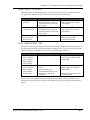
1
ALESIS M20 PROFESSIONAL 20-BIT DIGITAL RECORDER OWNER’S MANUAL FIRST EDITION VERSION 1.06 APPLIES TO OPERATING SOFTWARE VERSION 1.11 INCLUDES SOFTWARE VERSION 2.10 ADDENDUM 1999 ALESIS CORPORATION ALESIS M20 REFERENCE MANUAL 1.06 TABLE OF CONTENTS Important Safety Instructions and Compliance Notices ......................................vii Safety symbols used in this product ................................................................................................ vii Please follow these precautions when using this product: ............................................................ vii Instructions de Sécurité Importantes .................................................................................................ix Symboles utilisés dans ce produit ......................................................................................................ix Beim Benutzen dieses Produktes beachten Sie bitte die folgenden Sicherheitshinweise: ..............x Information to the User for Class A Digital Device (FCC Part 15, Class A)...................................xi CE Declaration of Conformity...........................................................................................................xii Overview, Setup, and Basics.............................................................................. 1 1.1 M20 Highlights ..............................................................................................................................1 1.2 Unpacking and Inspection ............................................................................................................2 1.3 AC Power Hookup ........................................................................................................................2 1.4 Line Conditioners and Protectors.................................................................................................3 1.5 About Audio Cables ......................................................................................................................3 1.6 Basic Audio Hookup .....................................................................................................................4 1.7 Use the Right Tape.........................................................................................................................4 1.8 Preparing the Tape Prior to Use ...................................................................................................4 1.9 Eject Tape Properly........................................................................................................................4 1.10 Backup ..........................................................................................................................................4 1.11 Operating Environment ..............................................................................................................5 1.12 Avoid Electromagnetic Interference...........................................................................................5 Control and Connector Basics ............................................................................ 1 2.1 About the Front Panel ...................................................................................................................1 2.2 About the Rear Panel.....................................................................................................................3 2.2a Punch Footswitch ...........................................................................................................3 2.2b Locate/Play or LRC Remote Control Jack ...................................................................3 2.2c Analog Inputs and Outputs...........................................................................................3 2.2d Time Code In and Out...................................................................................................3 2.2e Word Clock In and Out .................................................................................................3 2.2f ADAT Optical In and Out..............................................................................................3 2.2g Video In and Thru..........................................................................................................4 2.2h ADAT Sync In and Out .................................................................................................4 2.2i MIDI In and Out .............................................................................................................4 2.2j RS-422 In (Sony 9-Pin).....................................................................................................4 2.2k Meter Bridge/Remote Panel Out..................................................................................4 2.2l Power ...............................................................................................................................4 Editing M20 Operating Parameters .................................................................... 1 3.1 The Keypad ....................................................................................................................................1 3.1a 0 through 9 buttons ........................................................................................................1 3.1b Up Arrow/Yes/Upper Case.........................................................................................1 3.1c Down Arrow/No/Lower Case.....................................................................................1 3.1d Cursor Left .....................................................................................................................1 3.1e Cursor Right ...................................................................................................................1 3.1f Enter/Name ....................................................................................................................2 3.1g Selecting Pages ...............................................................................................................3 3.1h Selecting Page Parameters.............................................................................................3 3.1i Entering Parameter Values.............................................................................................3 3.2 The Edit Button..............................................................................................................................4 ALESIS M20 REFERENCE MANUAL 1.06 i Table of Contents 3.3 Editing Conventions......................................................................................................................4 Tape Formatting...............................................................................................1 4.1 Sample Rate Selection....................................................................................................................2 4.1a Pull-up and Pull-down Sample Rate Selection ............................................................3 4.2 Word Length Selection ..................................................................................................................3 4.3 Format a New Tape .......................................................................................................................4 4.4 Record Tracks While Formatting..................................................................................................4 4.5 Extend a Partially-Formatted Tape ..............................................................................................5 4.6 End Formatting ..............................................................................................................................5 4.7 Certify Tape Format ......................................................................................................................5 4.8 Reformatting: Caution!..................................................................................................................5 4.9 Lock Out Formatting (Safe Mode).................................................................................................6 4.10 Bulk Erasing .................................................................................................................................6 4.11 Recording a “Benchmark” Tape .................................................................................................6 Track Record Enabling and Monitoring ..............................................................1 5.1 Track Basics....................................................................................................................................1 5.2 Track Input Enables.......................................................................................................................2 5.3 Auto Input Switch .........................................................................................................................2 5.4 Record Enable ................................................................................................................................2 5.5 Safety Mode (All Safe)...................................................................................................................3 5.6 Monitor Inputs (All Input) ............................................................................................................3 Digital/Analog Input Selection and Routing ........................................................1 6.1 Digital Source.................................................................................................................................1 6.2 Input Select.....................................................................................................................................1 6.3 Track Output Selection..................................................................................................................2 6.4 Input Signal Routing (Analog And Digital).................................................................................2 6.4a Analog Input Routing ....................................................................................................3 6.4b Digital Input Routing.....................................................................................................4 6.4c Record-Enabling the Destination Tracks ......................................................................5 6.5 Aux Routing (input and output) ..................................................................................................6 Metering 1 7.1 Meter Mode Selection....................................................................................................................1 7.1a Clearing Peaks ................................................................................................................1 7.2 Meter Setup ....................................................................................................................................2 Transport Controls and Basic Recording .............................................................1 8.1 About the Tape Counter................................................................................................................1 8.2 Stop .................................................................................................................................................1 8.3 Play .................................................................................................................................................2 8.3a Play Button and Sync Status..........................................................................................2 8.4 Jog/Shuttle Wheel and Search......................................................................................................2 8.4a Jog Mode.........................................................................................................................2 8.4b Shuttle Mode ..................................................................................................................3 8.4c Search Button..................................................................................................................3 8.4d Search Master.................................................................................................................4 8.5 Other Transport Buttons ...............................................................................................................5 8.6 Record.............................................................................................................................................6 8.6a Punching Into Record ....................................................................................................6 8.6b Punching Out of Record ................................................................................................6 8.6c Record Write-Protection ................................................................................................7 8.6d Recording with a Footswitch ........................................................................................7 8.7 Rehearse Mode................................................................................................................................7 8.8 Auto Record ...................................................................................................................................8 ii ALESIS M20 REFERENCE MANUAL 1.06 Table of Contents 8.8a Setting Auto Record Punch Points................................................................................8 8.8b Enable Auto Record.......................................................................................................9 8.8c Set Auto Punch Points “On the Fly” .............................................................................9 Autolocation .................................................................................................... 1 9.1 Entering, Selecting, and Editing Location Points ........................................................................1 9.1A Set Locate........................................................................................................................1 9.1B Copy Tape Location........................................................................................................1 9.2 Deferred Play and Record.............................................................................................................3 9.3 Play-After-Locate (Auto Play) ......................................................................................................3 9.4 Loop Between Start and End Locate Points (Auto Return)........................................................3 9.4a Setting Loop Start and End Points................................................................................4 9.5 Set Pre-Roll .....................................................................................................................................4 9.6 Set Post-Roll ...................................................................................................................................5 9.7 Footswitch-Controlled Location...................................................................................................6 Varispeed ........................................................................................................ 1 SMPTE, Sync, and Offset Functions ................................................................... 1 11.1 Clock Source.................................................................................................................................1 11.2 SMPTE Rate..................................................................................................................................2 11.3 Time Code Source........................................................................................................................2 11.3a Internal ...........................................................................................................................2 11.4 Chase Reference ...........................................................................................................................3 11.5 Reference Counter .......................................................................................................................4 11.6 SMPTE Chase ...............................................................................................................................4 11.6a Set SMPTE Offset Value (Page 1) ................................................................................4 11.6b Set SMPTE Chase Mode (Page 2)................................................................................5 11.6c Set Flywheel Duration (Page 3) ...................................................................................5 11.6d Park Ahead (Page 4) ....................................................................................................5 11.7 Internal Generator........................................................................................................................6 11.7a Generator Mode (Page 1).............................................................................................6 11.7b Time Code Start Reference (Page 2) ...........................................................................7 11.7c ABS/Start Offset (Page 3) ............................................................................................7 11.7d User Bits (Page 4, or Page 3 if the Page 2 value is TC Track) ...................................8 11.8 Tape Offset ...................................................................................................................................8 11.9 Track Delay ................................................................................................................................ 10 MIDI Functions ................................................................................................. 1 12.1 MIDI Device (Page 1)...................................................................................................................1 12.2 MMC Output (Page 2) .................................................................................................................1 12.3 MTC Follow Gen (Page 3) ...........................................................................................................1 12.4 Send Sysex Dump? (Page 4)........................................................................................................1 12.5 Receive Sysex Dump? (Page 5) ...................................................................................................2 12.6 Send Software? (Page 6) ..............................................................................................................2 12.7 Load Software? (Page 7)..............................................................................................................2 Utility Menu ..................................................................................................... 1 13.1 Digital Out (Page 1) .....................................................................................................................1 13.2 Online Source (Page 2).................................................................................................................1 13.2a Online Button................................................................................................................1 13.2b Independent Slave Mode.............................................................................................2 13.3 Online Control (Page 3) ...............................................................................................................2 13.4 One-Button Record (Page 4)........................................................................................................2 13.5 Input Monitor (Page 5) ................................................................................................................2 13.6 Crossfade Time (Page 6)..............................................................................................................3 13.7 Time Code Output Level (Page 7) ..............................................................................................3 ALESIS M20 REFERENCE MANUAL 1.06 iii Table of Contents 13.8 Rewind/Fast Forward TC Output (Page 8)...............................................................................3 13.9 Unthread Timeout (Page 9).........................................................................................................3 13.10 Search Enable (Page 10).............................................................................................................4 13.11 Locate Before Play (Page 11) .....................................................................................................4 13.12 Mute Until Lock (Page 12).........................................................................................................4 13.13 Dynamic Punch (Page 13)..........................................................................................................4 13.14 Track Groups (Page 14) .............................................................................................................4 13.15 Save Data to Tape? (Page 15) ....................................................................................................4 13.16 Load Data from Tape? (Page 16) ..............................................................................................5 13.17 Tape Type (Page 17)...................................................................................................................5 13.18 ID Status (Page 18).....................................................................................................................5 13.19 User Bits (Page 19) .....................................................................................................................5 13.20 Error Rate (Page 20)...................................................................................................................6 13.21 Front Panel Software Version (Page 21)...................................................................................6 13.22 Software Version (Page 22) .......................................................................................................6 The LRC Remote Control....................................................................................1 Tutorials and Applications ................................................................................1 TUTORIAL 1: Multiple M20 Operation..............................................................................................1 Overview .................................................................................................................................1 Synchronizing Machines ........................................................................................................1 Automatic ID Renumbering...................................................................................................1 Master/Slave Interaction........................................................................................................2 Achieving Lock .......................................................................................................................2 Independent Slave Mode........................................................................................................2 Formatting Multiple Tapes ..................................................................................................................3 Master Format Enabled, Complete Format ..........................................................................3 Master Format Enabled, Format Extend...............................................................................3 Master Format Disabled.........................................................................................................4 Master Format Disabled, Format Extend..............................................................................4 TUTORIAL 2: Making Digital Backups ..............................................................................................5 Dealing with Damaged Tape .................................................................................................6 Making a 16-bit copy from a 20-bit master ...........................................................................6 TUTORIAL 3: Recording Digital Audio from Other Sources...........................................................7 Digital Clock Considerations .................................................................................................7 TUTORIAL 4: Combining M20s and ADATs ....................................................................................8 M20 Transport Speed .............................................................................................................8 Sample rate vs. Pitch Control.................................................................................................8 Input Monitoring ....................................................................................................................8 Polarity Differences ................................................................................................................9 TUTORIAL 5: Setting up Inputs........................................................................................................ 10 TUTORIAL 6: Updating M20 Software ............................................................................................ 11 TUTORIAL 7: Using the M20 with Unbalanced Inputs and Outputs............................................ 12 M20 SMPTE Synchronization Overview ..............................................................1 16.1 Synchronization Basics .................................................................................................................1 Master or Slave?......................................................................................................................1 Digital Timing Requirements.................................................................................................1 16.2 The One Clock Principle..............................................................................................................2 16.2a House Sync ...................................................................................................................2 16.2b “Genlocked” Time Code...............................................................................................2 16.3 Reference Counters vs. Clock Sources .......................................................................................3 16.3a Location Reference ........................................................................................................3 16.3b Reference Clock.............................................................................................................3 16.3 Offsets in the M20 ........................................................................................................................5 iv ALESIS M20 REFERENCE MANUAL 1.06 Table of Contents 16.3a SMPTE Chase Offset ....................................................................................................5 16.3b Internal Generator ABS Offset .....................................................................................6 16.3c Tape Offset....................................................................................................................6 16.4 SMPTE Time Code Rates and Types...........................................................................................7 16.4a Drop Frame....................................................................................................................7 16.4b Auto-detection of SMPTE Rates ..................................................................................7 16.4c VITC (Vertical Interval Time Code)............................................................................8 16.4d MTC (MIDI Time Code)...............................................................................................8 Time Code Tutorial ........................................................................................... 1 17.1 Generating Time Code onto a VCR............................................................................................1 17.2 Synchronizing Without a T/C Track...........................................................................................2 17.3 Recording a Time Code Track ....................................................................................................3 17.3a Recording SMPTE from ABS Time ..............................................................................3 Maintenance and Troubleshooting .....................................................................5 18.1 ADAT Head Cleaning .................................................................................................................5 18.1a Head Cleaning Cassettes (optional)............................................................................6 18.1b Manual Head and Tape Path Cleaning ......................................................................6 18.2 ADAT Head Life..........................................................................................................................7 18.2a Head Alignment ...........................................................................................................7 18.3 Tape Maintenance: Safe Tape .....................................................................................................8 18.3a Tape Wear.....................................................................................................................8 18.3b Care of ADAT Tapes ...................................................................................................8 18.4 Maintenance/Service...................................................................................................................9 18.4a Exterior Cleaning..........................................................................................................9 18.4b Maintenance .................................................................................................................9 18.4d Obtaining Repair Service........................................................................................... 10 M20 Hidden Functions ...................................................................................... 1 Power-On Button Combinations .........................................................................................................1 Miscellaneous Button Combinations ..................................................................................................1 Advanced Functions.............................................................................................................................3 Using The M20 Data Section Of Tape ................................................................. 1 General data section convention on the M20 .....................................................................................1 M20 Locate Points and SMPTE Offsets ..............................................................................................1 BRC ⇔ M20 Song Start / SMPTE Start Offset and Locate Point Map.............................................1 BRC ⇔ M20 Parameter Map ...............................................................................................................2 M20 Transport & System Error Messages........................................................... 1 M20 Major Feature Update: Version 2 ................................................................ 1 RS-422 (Sony 9-pin) slave operation....................................................................................................1 RS-422 Track Arm: On/Off....................................................................................................1 RS-422 Mapping: 1-2, OddEvn, (Local).................................................................................1 ID 1 offline with the CADI remote......................................................................................................2 CADI Tape and Reference Counter indications when ID 1 is offline...............................................2 Storing locate points when ID 1 is offline...........................................................................................2 Tape TC detection in fast wind modes ...............................................................................................3 Tape TC in the Tape Counter ..............................................................................................................4 Fixed mode time code generation: “TC Start Ref: Fixed” .................................................................4 Digital Scrub: “Dig Scan: On/Off, nn dB”..........................................................................................5 I/O Card as the digital source.............................................................................................................5 SMPTE Chase with the Stop button....................................................................................................5 Tape TC updating when in Input mode .............................................................................................5 Vari-Speed and Pull-Up/Down ..........................................................................................................5 ALESIS M20 REFERENCE MANUAL 1.06 v Table of Contents MIDI Thru .............................................................................................................................................6 New Utility page order ........................................................................................................................6 CADI display changes..........................................................................................................................6 Cassette Auto-Inject .............................................................................................................................6 Deck Standby Mode .............................................................................................................................7 Auto-Park After Formatting ................................................................................................................7 Deferred Eject .......................................................................................................................................7 New RS-422 Device ID .........................................................................................................................7 Improved SMPTE Clock Source Recognition.....................................................................................7 Sample Rate Change During Play/Record.........................................................................................7 vi ALESIS M20 REFERENCE MANUAL 1.06 IMPORTANT SAFETY INSTRUCTIONS AND COMPLIANCE NOTICES SAFETY SYMBOLS USED IN THIS PRODUCT This symbol alerts the user that there are important operating and maintenance instructions in the literature accompanying this unit. This symbol warns the user of uninsulated voltage within the unit that can cause dangerous electric shocks. PLEASE FOLLOW THESE PRECAUTIONS WHEN USING THIS PRODUCT: 1. Read these instructions. 2. Keep these instructions. 3. Heed all warnings. 4. Follow all instructions. 5. Do not use this apparatus near water. 6. Clean only with a damp cloth. Do not spray any liquid cleaner onto the faceplate, as this may damage the front panel controls or cause a dangerous condition. 7. Do not block any of the ventilation openings. Install in accordance with the manufacturer's instructions. 8. Do not install near any heat sources such as radiators, heat registers, stoves, or other apparatus (including amplifiers) that produce heat. (more on next page) ALESIS M20 REFERENCE MANUAL 1.06 vii Safety Notices 9. Do not defeat the safety purpose of the polarized or grounding-type plug. A polarized plug has two blades with one wider than the other. A grounding-type plug has two blades and a third grounding prong. The wide blade or the third prong is provided for your safety. When the provided plug does not fit into your outlet, consult an electrician for replacement of the obsolete outlet. 10. Protect the power cord from being walked on or pinched particularly at plugs, convenience receptacles, and the point where they exit from the apparatus. 11. Use only attachments/accessories specified by the manufacturer. 12. Use only with a cart, stand, tripod, bracket, rack, or table specified by the manufacturer, or sold with the apparatus. When a cart is used, use caution when moving the cart/apparatus combination to avoid injury from tip-over. Alesis recommends the use of standard 19” racks designed for use with professional audio or music equipment, and the use of rear rack rail supports or sliders. In any installation, make sure that injury or damage will not result from cables pulling on the apparatus and its mounting. 13. Unplug this apparatus during lightning storms or when unused for long periods of time. 14. Refer all servicing to qualified service personnel. Servicing is required when the apparatus has been damaged in any way, such as when the power-supply cord or plug is damaged, liquid has been spilled or objects have fallen into the apparatus, the apparatus has been exposed to rain or moisture, does not operate normally, or has been dropped. 15. This unit produces heat when operated normally. If this unit is installed in a rack, make sure that there is proper ventilation when operated. Do not operate in an enclosed rack with closed front and back doors. If there are other units in the rack that generate a large amount of heat, spread them apart. Do not sandwich this product between two large heat-producing units. 16. This product, in combination with an amplifier and headphones or speakers, may be capable of producing sound levels that could cause permanent hearing loss. Do not operate for a long period of time at a high volume level or at a level that is uncomfortable. If you experience any hearing loss or ringing in the ears, you should consult an audiologist. viii ALESIS M20 REFERENCE MANUAL 1.06 Safety Notices INSTRUCTIONS DE SÉCURITÉ IMPORTANTES SYMBOLES UTILISÉS DANS CE PRODUIT Ce symbole alèrte l’utilisateur qu’il existe des instructions de fonctionnement et de maintenance dans la documentation jointe avec ce produit. Ce symbole avertit l’utilisateur de la prèsence d’une tension non isolèe à l’intèrieur de l’appareil pouvant engendrer des chocs èlectriques. Veuillez suivre ces prècautions lors de l’utilisation de l’appareil: 1. Lisez ces instructions. 2. Gardez ces instructions. 3. Tenez compte de tous les avertissements. 4. Suivez toutes les instructions. 5. N’utilisez pas cet allareil à proximitè de l’eau. 6. Ne nettoyez qu’avec un chiffon humide. Ne pas vaporiser de liquide nettoyant sur l’appareil, cela pourrait abîmer les contrôles de la face avant ou engendrer des conditions dangeureuses. 7. Installez selon les recommandations du constructeur. 8. Ne pas installer à proximilè de sources de chaleur comme radiateurs, cuisinière ou autre appareils (don’t les amplificateurs) produisant de la chaleur. 9. Ne pas enlever la prise de terre du cordon secteur. Une prise murale avec terre deux broches et une troisièrme relièe à la terre. Cette dernière est prèsente pour votre sècuritè. Si le cordon secteur ne rentre pas dans la prise de courant, demandez à un èlectricien qualifiè de remplacer la prise. 10. Evitez de marcher sur le cordon secteur ou de le pincer, en particulier au niveau de la prise, et aux endroits où il sor de l’appareil. 11. N’utilisez que des accessoires spècifiès par le constructeur. 12. N’utilisez qu’avec un stand, rack ou table conçus pour l’utilisation d’audio professionnel ou instruments de musique. Dans toute installation, veillez de ne rien endommager à cause de câbles qui tirent sur des appareils et leur support. 13. Dèbranchez l’appareil lors d’un orage ou lorsqu’il n’est pas utilisè pendant longtemps. 14. Faites rèparer par un personnel qualifiè. Une rèparation est nècessaire lorsque l’appareil a ètè endommagè de quelque sorte que ce soit, par exemple losrque le cordon secteur ou la prise sont endommagès, si du liquide a coulè ou des objets se sont introduits dans l’appareil, si celui-ci a ètè exposè à la pluie ou à l’humiditè, ne fonctionne pas normalement ou est tombè. 15. Cet appareil produit de la chaleur en fonctionnement normal. Si cet appareil est utilisè dans un rack, veillez à sa bonne ventilation lors de son utilisation. Ne pas faire fonctionner dans un rack fermè. S’il y a d’autres appareils dans le rack gènèrant beaucoup de chaleur, èloignez les. Ne pas intercaler cet appareil entre deux appareils produisant beaucoup de chaleur. ALESIS M20 REFERENCE MANUAL 1.06 ix Safety Notices 16. Ce produit, utilisè avec un amplificateur et un casque ou des enceintes, est capable de produite des niveaux sonores pouvant engendrer une perte permanente de l’ouïe. Ne l’utilisez pas pendant longtemps à un niveau sonore èlevè ou à un niveau non confortable. Si vous remarquez une perte de l’ouïe ou un bourdonnement dans les oreilles, consultez un spècialiste. BEIM BENUTZEN DIESES PRODUKTES BEACHTEN SIE BITTE DIE FOLGENDEN SICHERHEITSHINWEISE: 1. Lesen Sie die Hinweise. 2. Halten Sie sich an die Anleitung. 3. Beachten Sie alle Warnungen. 4. Beachten Sie alle Hinweise. 5. Bringen Sie das Gerät nie mit Wasser in Berührung. 6. Verwenden Sie zur Reinigung nur ein weiches Tuch. Sprühen Sie keine flüssiger Reiniger auf die Oberfläche, dies könnte zur Beschädigung der Vorderseite führen und auch weitere Schäden verursachen. 7. Halten Sie sich beim Aufbau des Gerätes an die Angaben des Herstellers. 8. Stellen Sie das Gerät nich in der Nähe von Heizkörpern, Heizungsklappen oder anderen Wärmequellen (einschließlich Verstärkern) auf. 9. Verlegen Sie das Netzkabel des Gerätes niemals so, daß man darüber stolpern kann oder daß es gequetscht wird. 10. Benutzen Sie nur das vom Hersteller empfohlene Zubehör. 11. Verwenden Sie ausschließlich Wagen, Ständer, Racks oder Tische, die speziell für professionelle Audio- und Musikinstrumente geeignet sind. Achten Sie immer darauf, daß die jeweiligen Geräte sicher installiert sind, um Schäden und Verletzungen zu vermeiden. Wenn Sie einen Rollwagen benutzen, achten Sie darauf, das dieser nicht umkippt, um Verletzungen auszuschließen. 12. Ziehen Sie während eines Gewitters oder wenn Sie das Gerät über einen längeren Zeitraum nicht benutzen den Netzstecher aus der Steckdose. 13. Die Wartung sollte nur durch qualifiziertes Fachpersonal erfolgen. Die Wartung wird notwendig, wenn das Gerät beschädigt wurde oder aber das Stromkabel oder der Stecker, Gegenstände oder Flüssigkeit in das Gerät gelangt sind, das Gerät dem Regen oder Feuchtigkeit ausgesetzt war und deshalb nicht mehr normal arbeitet oder heruntergefallen ist. 14. Bei normalem Betrieb des Gerätes kommt es zu Wärmeentwicklungen. Wenn Sie das Gerät in einem Rack eingebaut haben, sollte während des Betriebes die Zufuhr von Kühlluft stets gewährleitstet sein. Arbeiten Sie nie bei geschlossenem Rack. Bei mehreren Rackgeräten sollten diese mit einem geringen abstand voneinander eingebaut werden. Stapeln Sie dieses Gerät nicht zwischen Geräten mit hoher Wärmeentwicklung. 15. Dieses Produkt kann in Verbindung mit einem Verstärker und Kopfhörern oder Lautsprechern Lautstärkepegel erzeugen, die anhaltende Gehörschäden verursachen. Betreiben Sie es nicht über längere Zeit mit hoher Lautstärke oder einem Pegel, der Ihnen unangenehm is. Wenn Sie ein Nachlassen des Gehörs oder ein Klingeln in den Ohren feststellen, sollten Sie einen Ohrenarzt aufsuchen. x ALESIS M20 REFERENCE MANUAL 1.06 Safety Notices INFORMATION TO THE USER FOR CLASS A DIGITAL DEVICE (FCC PART 15, CLASS A) This equipment has been tested and found to comply with the limits for a class A digital device pursuant to Part 15 of the FCC Rules. These limits are designed to provide reasonable protection against harmful interference when the equipment is operated in a commercial environment. This equipment generates, uses and can radiate radio frequency energy and, if not installed and used in accordance with the instructions, may cause interference to radio communications. Operation of this equipment in a residential area is likely to cause interference in which case the user will be required to correct the interference at his own expense. The user is cautioned that changes and modifications made to the equipment without the approval of manufacturer could void the user’s authority to operate this equipment. Use only shielded and grounded cables with this equipment to ensure compliance with FCC Rules. INDUSTRY CANADA (DIGITAL APPARATUS) INTERFERENCE-CAUSING EQUIPMENT STANDARD ICES-003 ISSUE 2 This Class A digital apparatus meets all requirements of the Canadian InterferenceCausing Equipment Regulations. ALESIS M20 REFERENCE MANUAL 1.06 xi Safety Notices CE DECLARATION OF CONFORMITY Manufacturer’s Name: Alesis Corporation Manufacturer’s Address: 1633 26th Street Santa Monica, CA 90404 USA declares, that the product: Product Name: Product Type: M20 Modular Digital Multitrack Recorder conforms to the following Standards: Application of Council Directive: 89/336/EEC; 73/23/EEC Safety: EN 60 065 (1993) First Edition, Amendment No.1 (1994) EMC: EN 55022:1988 Class A IEC 801-2:1991 2nd Edition, 4kV direct, 8kV air IEC 801-3:1984 2; 3V/m 150MHz-1GHz IEC 801-4:1988 1st Edition 2; 1kV, 0.5kV All tests were performed with fully-shielded cabling. European Contact: Sound Technology 17 Letchworth Point, Lechworth, Hertfordshire, SG6 1ND, England. Phone: +44.1462.480000 Fax: +44.1462.480800 April, 1998 xii ALESIS M20 REFERENCE MANUAL 1.06 CHAPTER 1 OVERVIEW, SETUP, AND BASICS The Alesis M20 is an 8-track digital tape recorder that records on S-VHS videotape cassettes. It is compatible with the ADAT format used with several other digital recorders (Alesis ADAT, ADAT XT, LX20, and XT20; Studer V-Eight; Fostex RD-8 and CX-8; and Panasonic MDA-1). 1.1 M20 HIGHLIGHTS • Direct-drive full-servo S-VHS transport, designed for continuous shuttling and heavyduty professional use • Two available bit resolutions: 16-bit standard ADAT Type I, and 20-bit ADAT Type II • • • • • • • • • • • • 24-bit A/D and D/A converters +4 dBu balanced XLR and ELCO (multipin) connectors Selectable 16-bit dithered output for transfer to 16-bit systems Jog/shuttle wheel for fast navigation Analog Aux track for superb scrub and jog monitoring ADAT , SMPTE, video and word clock synchronization capabilities Dedicated SMPTE time code track Optional EC-1 8 channel AES/EBU digital audio interface Two custom vacuum fluorescent displays Extensive error reporting capability Optional CADI remote control Optional RMD remote meter display ALESIS M20 REFERENCE MANUAL 1.06 1-1 Overview, Setup and Basics, Chapter 1 1.2 UNPACKING AND INSPECTION Please retain the M20’s shipping carton, which is designed to protect the unit during shipping, in the unlikely event that you need to return the M20 for servicing. Some carriers have restrictions on shipping electronic equipment without the original packing. The shipping carton contains: § § § § § § § M20 with the same serial number shown on shipping carton Power Cable Optical Cable M20 LRC (remote control unit) This instruction manual Blank S-VHS ST-120 cassette Alesis warranty card In order to be advised of future updates, please register your purchase immediately by filling out the warranty card and mailing it back to Alesis. 1.3 AC POWER HOOKUP 1 Make sure the M20 is turned off. It’s good practice not to turn on the M20 until all other cables are hooked up. 2 Before plugging in to AC power, note that the M20’s IEC-spec AC cord (do not substitute any other AC cord) must feed a 3-pin outlet, where the third, round pin connects to ground. The ground connection is an important safety feature designed to keep the chassis of electronic devices at ground potential. Unfortunately, the presence of a third ground pin does not always indicate a properly grounded outlet; check this with an AC line tester. If the outlet is not grounded, consult with a licensed electrician. 3 Plug the power cord’s female end into the M20’s power input socket, and the male (plug) end into any AC power source from 90 to 250 volts, 50 or 60 Hz. Your M20 includes the correct power cord for your country or local area. When using an M20 abroad , use only the following alternative power cords approved for use with ADAT: 1-2 • For 90-120 VAC 50/60 Hz operation in the US, Canada and/or Japan, use Alesis UL/CSA power cord #7-41-0001. • For 240 VAC 50 Hz operation in England, use Alesis UK power cord #7-41-0004. • For 220 VAC 50 Hz operation in Europe and Scandinavia, use Alesis EU power cord #7-41-0002. • For 240 VAC 50 Hz operation in Australia, use Alesis AS power cord #7-41-0003. ALESIS M20 REFERENCE MANUAL 1.06 Chapter 1, Overview, Setup and Basics Alesis cannot be responsible for problems caused by using the M20 or any associated equipment with improper AC wiring. 1.4 LINE CONDITIONERS AND PROTECTORS Although the M20 tolerates typical voltage variations, the AC line voltage may contain spikes or transients that can possibly stress your gear and, over time, cause a failure. There are three main ways to protect against this, listed in ascending order of cost and complexity: • Line spike/surge protectors. Relatively inexpensive, these help protect against strong surges and spikes (they usually need to be replaced after enduring an extremely strong spike). • Line filters. These generally combine spike/surge protection with filters that remove some line noise (dimmer hash, transients from other appliances, etc.). • Uninterruptible power supply (UPS). This is the best option. A UPS provides power even if the AC power line fails completely. Intended for computer applications, a UPS allows an orderly shutdown in the event of a power outage. Furthermore, the isolation it provides from the power line minimizes all forms of interference ó spikes, noise, etc. 1.5 ABOUT AUDIO CABLES The connections between the M20 and your studio are your music’s lifeline. Use only high quality, low-capacitance, shielded cables with a stranded (not solid) internal conductor and low-resistance shield. Although quality cables cost more, they make a difference. When routing cables: • Do not bundle audio cables with AC power cords. • Avoid running audio cables near sources of electromagnetic interference such as transformers, monitors, computers, etc. • Do not place cables where they can be stepped on. Stepping on a cable may not cause immediate damage, but it can compress the insulation between the center conductor and shield (degrading performance) or reduce the cable’s reliability. • Avoid twisting the cable or making sharp, right angle turns. • Never unplug a cable by pulling on the wire itself. Always unplug by firmly grasping the plug’s body, and pulling directly outward. • Although Alesis does not endorse any specific product, chemicals such as Tweek and Cramolin, when applied to electrical connectors, are claimed to improve the electrical contact between connectors. ALESIS M20 REFERENCE MANUAL 1.06 1-3 Overview, Setup and Basics, Chapter 1 1.6 BASIC AUDIO HOOKUP When connecting audio cables and/or turning power on and off, turn off all devices in your system and turn down your monitor system’s volume controls. The M20 provides 10 pairs of XLR connectors (8 pairs for audio in/out, 1 pair for the auxiliary analog channel, and 1 pair above for SMPTE time code). The nine sets of audio XLRs connect to your mixer’s tape or line inputs and outputs. An additional multipin ELCO connector , wired in parallel with the 8 XLR audio pairs, can connect to a “snake” that goes to your mixer. Several manufacturers make ADAT/M20-specific cables that break out the ELCO connector into individual ins and outs. 1.7 USE THE RIGHT TAPE Use only premium quality, name brand S-VHS cassettes such as Quantegy 489 DM Digital Mastering Audio Tape, or Alesis ADAT Mastering Audio Cassettes. Other acceptable brands include Maxell XR-S Black, JVC XZ, Sony DASV, BASF Digital Master 938, Apogee AA-40, HHB ADAT45, and TDK SP Super Pro. The cassette shell, hubs, rollers and tape guides in SVHS cassettes are precision devices that properly handle and protect the tape within them. Caution: Do not use VHS cassettes. While they may appear to function properly at first, their less-than-premium formulation will decrease the reliability of your recording. They may also shed oxide and leave behind a coating of dirt that will interfere with future recordings, even if you switch back to premium quality tape. Defective tape may even clog the head, requiring service. Trust your work only to premium quality S-VHS tape. 1.8 PREPARING THE TAPE PRIOR TO USE Fast forward and rewind all new tapes at least once from end to end before attempting to format and record on them. This important step “unpacks” the tape properly, and leads to far more reliable operation (this is also recommended practice for DAT tapes). 1.9 EJECT TAPE PROPERLY After a session, eject the tape and put it in a protective case. Do not: • Leave the tape in the M20 when power is off. • Leave the tape halfway ejected in the well. Always remove completely after ejection. • Eject in the middle of recorded material. Malfunctions that could possibly damage the tape are statistically most likely to occur when inserting or ejecting a tape, so always eject where nothing is recorded. 1.10 BACKUP Accidents can happen ó so, like computer floppy disks and hard disks, back up your M20 tapes to another M20 or ADAT using the fiber optic digital connector (see Tutorial 2 for step-by-step instructions on backing up M20 tapes). 1-4 ALESIS M20 REFERENCE MANUAL 1.06 Chapter 1, Overview, Setup and Basics 1.11 OPERATING ENVIRONMENT Mount the M20 in an equipment rack (requires 4 rack spaces) or place it on a table or shelf. Alesis advises against tilting the recorder; keep it horizontal. Also remember that heat shortens the life of electronic equipment. Please observe the following: • The M20 is designed to perform properly over a range of ambient temperatures from 10° C to +40° C (50° F to 104° F), in up to 80% non-condensing humidity. These are not absolute limits, but Alesis cannot guarantee that the M20 will meet its published specs or remain reliable if operated outside of these ranges. • Always allow adequate ventilation behind the M20. Do not seal any enclosure that holds the M20. It is not necessary to leave an empty rack space above or below the M20. • You will need to remove the screw-on feet from the bottom of the M20 if any equipment will be mounted directly below it. 1.12 AVOID ELECTROMAGNETIC INTERFERENCE Like all tape machines, the M20 uses magnetic tape that can be sensitive to electromagnetic interference. Generally this is not a problem, but avoid mounting the M20 next to devices that generate strong magnetic fields such as power amplifiers, monitors and video display devices, speakers, etc., and always treat your tapes with care. In particular, avoid excess heat, cold, and humidity. ALESIS M20 REFERENCE MANUAL 1.06 1-5 Overview, Setup and Basics, Chapter 1 Figure 1 (M20 Front Panel) 1-6 ALESIS M20 REFERENCE MANUAL 1.06 CHAPTER 2 CONTROL AND CONNECTOR BASICS 2.1 ABOUT THE FRONT PANEL Referring to Fig. 1, the front panel includes: • S-VHS cassette door and Eject button • Main vacuum fluorescent display (toward the center) with two sets of 10-character 7segment readouts. The left readout shows the current tape location. The right readout shows information such as incoming SMPTE time, locate address, current offset, etc. A 24-character alphanumeric display above the 7-segment display shows edit location points, pre/post-roll times, pitch value, and various messages. • 9 function buttons (below the main display) • 5 transport buttons • 4 locate-related buttons • Rehearse button • Jog/shuttle wheel and search button • 15-button numeric keypad for data entry • 15 editing switches • Secondary vacuum fluorescent display with VU meters for the 8 audio channels and auxiliary track, the time code track signal, error lights, track input and record lights, and input selection and routing indicators. • 22 track enable and track record buttons • 6 routing, source selection, and metering buttons • Online/offline button • Recessed power switch ALESIS M20 REFERENCE MANUAL 1.06 2-1 Control and Connector Basics, Chapter 2 Figure 2 (M20 Rear Panel with optional EC-1 AES/EBU Card) 2-2 ALESIS M20 REFERENCE MANUAL 1.06 Chapter 2, Control and Connector Basics 2.2 ABOUT THE REAR PANEL Referring to Fig. 2, the rear panel includes: 2.2A PUNCH FOOTSWITCH This allows foot-controlled punch in and out. Use a momentary footswitch, either normallyopen or normally-closed (the M20 senses the type on power-up and calibrates itself). 2.2B LOCATE/PLAY OR LRC REMOTE CONTROL JACK This 1/4” jack accepts a momentary footswitch (normally closed or open) to allow footcontrolled location functions. It also accepts the LRC remote control (see Chapter 14) for remote access of transport functions. Note: If using a normally open footswitch, the footswitch and LRC remote control can be interchanged, or used simultaneously with a Y-cord, without restarting (powering down and powering up) the M20. However, if using a normally closed footswitch, the M20 unit should be restarted after switching from footswitch to remote control and vice-versa. 2.2C ANALOG INPUTS AND OUTPUTS 18 XLR connectors carry the +4 dBu balanced analog inputs and outputs. There are 9 audio input and output channels (channels 1 through 8 plus Aux). Channels 1 through 8 inputs and outputs are also accessible through a multi-pin ELCO connector, which is wired in parallel with the XLR inputs and outputs. All XLR connectors are wired with pin 2 “hot,” in accordance with IEC standards. 2.2D TIME CODE IN AND OUT The time code input and output use balanced XLR connectors for use with SMPTE/EBU standard time code systems. Time code input allows the M20 to be slaved to an external device; time code output provides timing reference to an external device. 2.2E WORD CLOCK IN AND OUT These are BNC connector, TTL-level word clock inputs and outputs. A master word clock signal, which the M20 can provide, allows synchronizing the audio data stream for all digital audio devices in a system. If a master word clock signal already exists, the M20 can sync to it. 2.2F ADAT OPTICAL IN AND OUT The optical input and output are an industry-standard digital audio interface, pioneered by Alesis, that carries 8 digital audio channels (with up to 24 bits of resolution) on a single fiber optic cable. The standard cable is a 1mm diameter plastic fiber with Toslink connectors. One 1-meter cable is provided with the M20; additional cables of different lengths are available from your dealer. Applications include digitally dubbing from one deck to another, interfacing with hard disk recording systems and synthesizers, and feeding translators that change the ADAT optical format to other formats. ALESIS M20 REFERENCE MANUAL 1.06 2-3 Control and Connector Basics, Chapter 2 2.2G VIDEO IN AND THRU The BNC connector video input (with 75 ohm termination switch) accepts composite video as well as black burst video inputs. 2.2H ADAT SYNC IN AND OUT These 9-pin D connectors synchronize multiple ADATs together to single-sample accuracy. Computer interface cards with ADAT sync, such as the Alesis ADAT-PCR, allow transferring ADAT data to and from a computer for editing with single-sample accuracy. Interface cards without ADAT sync allow transferring ADAT data with 1/4 frame accuracy via MIDI Time Code. 2.2I MIDI IN AND OUT These 5-pin DIN connectors can output and/or receive MIDI Machine Control commands, save and load sysex dumps defining the M20 status, allow for software updates via MIDI sysex files, and output MTC (MIDI Time Code) when selected. 2.2J RS-422 IN (SONY 9-PIN) This 9-pin D connector connects to a video editor or other controller that supports the Sony 9-pin protocol. This feature will not be operational until M20 Version 2.0 software becomes available. 2.2K METER BRIDGE/REMOTE PANEL OUT This RJ-45 connector connects to an optional remote controller like the Alesis CADI remote, and/or RMD meter bridge. 2.2L POWER The IEC-standard, grounded AC input plug accepts AC voltages from 90 to 250 volts, eliminating the need for transformers or voltage switches. 2-4 ALESIS M20 REFERENCE MANUAL 1.06 CHAPTER 3 EDITING M20 OPERATING PARAMETERS 3.1 THE KEYPAD The keypad block contains switches for editing the various parameters that control the M20’s features. 3.1A 0 THROUGH 9 BUTTONS Use the 10 numeric keys to enter number parameter values and letters for names. When editing a parameter value, pressing a key enters its associated number. When editing a name, pressing a key cycles through the letters indicated on the keycap (e.g., pressing 7 repeatedly cycles through 7, s, t, u, v, 7, s, t…etc.). 3.1B UP ARROW/YES/UPPER CASE This key: • Increments parameter values, as well as scrolls up through a list of parameter values. Holding this button for 2 or more seconds increases the speed at which the values increment. After 7 seconds, this speed increases again. • Enters “Yes” in response to Yes/No queries. • In a sign (polarity) field, selects the positive (+) sign. • In a name field, changes lower case letters to UPPER CASE. 3.1C DOWN ARROW/NO/LOWER CASE This key: • Decrements parameter values, as well as scrolls down through a list of parameter values. Holding this button for 2 or more seconds increases the speed at which the values decrement. After 7 seconds, this speed increases again. • Enters “No” in response to Yes/No queries. • In a sign (polarity) field, selects the negative (-) sign. • In a name field, changes UPPER CASE letters to lower case. 3.1D CURSOR LEFT When editing, this key positions the cursor (a single underline character, showing that a parameter is ready for editing) under the next field to the left. (Note: It will not move across page boundaries.) 3.1E CURSOR RIGHT When editing, this key positions the cursor (a single underline character) under the next field to the right. (Note: It will not move across page boundaries.) ALESIS M20 REFERENCE MANUAL 1.06 3-1 Editing M20 Parameters, Chapter 3 3.1F ENTER/NAME This key has two main uses: • Speed up numeric entry by eliminating the need for “leading zeroes.” For example, the varispeed setting is a 3-digit value. Instead of having to key in something like 0 - 0 - 9, you can simply key in 9, then press Enter. • Edit location point names. When the locate time is the currently selected field, pressing the Enter/Name button positions the cursor at the first character of the name. The cursor buttons now select individual characters within the name field or other displayed fields; use the keypad buttons to change the character. For upper case, use the Up Arrow. For lower case, use the Down Arrow. To exit the name field, press the Enter/Name button again. Using the default name list instead of entering letters individually: An additional name editing option is available. Holding down the Name button while using the Up/Down buttons scrolls through a default set of 16 generic names (e.g., Verse 1, Chorus, Bridge, etc.). This list may be customized for your working style. To customize the default set of names: 3-2 1 Select the default name to be changed. 2 Edit it. 3 To store the new name in the default name list, hold the Enter/Name button and press the Record button. ALESIS M20 REFERENCE MANUAL 1.06 Chapter 3, Editing M20 Parameters 3.1G SELECTING PAGES Most buttons have at least one associated display page, which contains one or more parameters. If there are multiple pages, the main display’s left side shows the current page number; repeatedly pressing the associated button cycles through the pages. Shortcut: To access a particular page directly, hold the associated button and use the keypad to enter the desired single-digit page number. Functions with double-digit page numbers (e.g., the Utility function) have a different access procedure. Hold the current function button and press the 2 digits within 3 seconds of each other. To select a single digit page number (1 through 9), press and hold the current function button and either: • Enter 0, then the digit; or • Press the single digit, then the Enter button. (Note: If the Enter button is not pressed within 3 seconds, the display reverts to its previous state.) 3.1H SELECTING PAGE PARAMETERS To select the desired parameter for editing in multi-parameter pages, position the cursor with the Left or Right Cursor button under the parameter value’s rightmost digit. 3.1I ENTERING PARAMETER VALUES Entering complete values: Use the numeric keypad and enter the most significant digit first. Enter all of a field’s digits to complete the entry. The cursor automatically advances through the fields. Increment/decrement a value by one: Use the keypad’s Up and Down buttons. Holding the Up or Down button for more than 2 seconds increments (or decrements) the value continuously. The value above the cursor will be changed. If the value goes beyond a boundary (for example, increasing from 59 seconds to 0), the next field will be calculated automatically (in this example, the minute field will be automatically increased). ALESIS M20 REFERENCE MANUAL 1.06 3-3 Editing M20 Parameters, Chapter 3 3.2 THE EDIT BUTTON The Edit button toggles the M20 in and out of Edit Mode. Enabling Edit mode (button lit) allows editing parameter values for the functions grouped with the Edit button: Track Delay, Tape Offset, SMPTE Chase, Internal Gen, Format, Pre-Roll, Post-Roll, Auto Return, and Auto Record. While Edit is On, only the currently selected function’s switch will light. However, the M20 retains the current on/off status of all switches, and these become visible after exiting Edit mode. Note: Don’t be confused! Editing a function does not turn it on. For example, while editing the Post Roll value the Post Roll switch will be lit, but if the light goes out when you leave Edit mode, Post Roll is not yet active. If the Edit LED is not lit, pressing the various switches toggles these functions on and off. Example: If you’ve used the Edit button to edit the amount of Tape Offset and the Edit button is off, turning on the Tape Offset button enables the programmed amount of offset. Pressing the Display, Pitch Value, or Utility button will also exit Edit mode and enter the Display, Pitch, or Utility pages, respectively. 3.3 EDITING CONVENTIONS 3-4 • The rightmost 7-segment display shows locate times in hours, minutes, seconds, frames, subframes and samples. Subframes equal 1/100th of a frame and range from 0…99. The number of samples per subframe depends on the Tape Counter and Sample Rate settings. If the tape counter is in ABS Time mode, there are always 15 samples per subframe in 48 kHz and 14 per subframe at 44.1 kHz. If the counter is in a SMPTE Time Code mode and the sample rate is 48 kHz, Sample steps range from 0 - 15 for 30 frames/sec, 0 - 15 or 16 for 29.97 frames/sec, 0 - 18 for 25 frames/sec, and 0 - 19 for 24 frames/sec. • A lit arrow above the subframe (SF) indicator indicates that there is a non-zero sample value. To access the samples field, with the subframe field selected press the Right Cursor button. This selects a second page that shows only the sample value. • When editing any tape address, the cursor steps in fields (hours, minutes, seconds, frames, subframes, and samples) instead of stepping every digit. • When editing any tape address, entering digits with the keypad automatically advances the cursor or selected field (using the Up/Down Arrows does not advance the field) • When editing a field in the 7-segment display, the digit(s) of the selected (and currently editable) field will flash. ALESIS M20 REFERENCE MANUAL 1.06 CHAPTER 4 TAPE FORMATTING Formatting is essential to the ADAT system. It creates a sample-accurate time reference (i.e., it’s accurate to 1/48,000th of a second when recording at 48 kHz) on each tape, in addition to block ID codes, linear control track, and other essential markers. This provides tight synchronization ó far better than SMPTE sync ó between ADAT-compatible devices, as well as precision tape counter readings and intelligent autolocation functions. The format process first records 15 seconds of leader (the display shows LEAd), followed by two minutes of data (the display shows dAtA), then ABS time code starting at 00:00:00.00 and continuing to the end of the tape. Caution: formatting a tape erases all material on all tracks. Always check that the tape is either blank or contains unwanted material before formatting. You can either: • Format a tape completely before recording (recommended) • Format while you are recording, for as long as needed • Extend the format of an incompletely formatted tape Before formatting a blank tape, you must select: • The sample rate (44.1 or 48 kHz) • The word length (20-bit for Type II tapes, or 16-bit for compatibility with Type I ADAT and ADAT-XT tapes) ALESIS M20 REFERENCE MANUAL 1.06 4-1 Formatting Tape, Chapter 4 4.1 SAMPLE RATE SELECTION Choose between 44.1 kHz (CD/consumer standard) or 48 kHz (DAT/professional standard). Here are some general hints: • If mixing the tape through a digital mixer for a CD master, use 44.1 kHz to avoid sample rate conversion. • If mixing the tape through an analog mixer, use 48 kHz for slightly better high frequency response. • If you plan to transfer M20 tracks over to a hard disk system for editing, note that audio recorded at 48 kHz requires about 10% more storage capacity than the equivalent audio recorded at 44.1 kHz. The following sample rate selection procedure assumes that Clock Source is set to INTernal. Operation Select sample rate You press… Sample Rate button You see… Sample Rate block toggles between 44.1 or 48 kHz (default) with each Sample Rate button press About changing sample rates: The sample rate chosen during the format process does not have to be used during playback or recording of that particular tape; the ADAT format always allows you to override the default sample rate from the tape. When loading a formatted tape, the sample rate will automatically switch to the tape’s original settings. You may change the sample rate setting to playback or record with a different sample rate, but the sample rate indicator will flash to indicate that it is not at the original setting. Changing the sample rate directly affects the pitch and speed of any audio recorded. When extending a format, the sample rate will automatically assume the existing format’s values. There is no way to format a tape with a “44.1” marker on one section and a “48” marker on another. 4-2 ALESIS M20 REFERENCE MANUAL 1.06 Chapter 4, Formatting Tape 4.1A PULL-UP AND PULL-DOWN SAMPLE RATE SELECTION The Sample Rate button is also used to select the respective 0.1% pull-up and pull-down rates. A pull-up is available with a 30 fps SMPTE rate only. A pull-down is available with a 29.97 fps SMPTE rate only. Use pull-up or pull-down after a standard tape format: It is not necessary to pre-select a pull-up or pull-down prior to formatting since the “pull” status is not recalled when tapes are subsequently reinserted. Use the pull-up/pull-down feature after formatting your tape. If you are formatting and recording simultaneously, using the pull-up/pull-down feature may be appropriate. Operation Select a Pull-up sample rate Select a Pull-down sample rate Return to a normal 44.1/48 kHz sample rate from a “pulled” rate You press… …and hold Sample Rate button then press Up button …and hold Sample Rate button then press Down button …and hold Sample Rate button then press the 0/Space button You see… “+0.1%” displayed in the Sample Rate block “- 0.1%” displayed in the Sample Rate block Sample Rate block returns to normal sample rate display (44.1 or 48 kHz) Refer to section 16.4 for more information on pull-up and pull-down. 4.2 WORD LENGTH SELECTION Select 20 bits unless you want compatibility with older, Type I format ADAT tapes. Operation Initiate word length selection Select word length You press… Edit button, then Format button Up or Down Arrow button so that the display shows… ALESIS M20 REFERENCE MANUAL 1.06 You see… Display says “Format Data Type” and 16 or 20 bits The desired word length (16 or 20) 4-3 Formatting Tape, Chapter 4 4.3 FORMAT A NEW TAPE Use only S-VHS blank tapes formulated specifically for Super VHS video or digital audio applications. Never use standard VHS tapes. “Exercise” the tape: Before formatting, fast forward the tape to the end and rewind it to even out the tape pack and sweep any contaminants off the tape. Operation Insert blank tape Enable formatting Initiate formatting You press… Tape into tape chamber. Do this gently; the machine will “grab” the tape Format button (with Edit button off) Hold Record then press Play You see… Display shows “noFO,” Format button flashes All record lights turn on Display message advises you of formatting progress What happens between initiating formatting and the actual process of formatting depends on the current tape status. Tape status Unformatted, at start of tape Unformatted, partway through tape While rewinding from current position, goes from unformatted to previously formatted portion Formatted, in Leader or Data section of tape Formatted, in Audio section of tape The M20… Begins formatting immediately Rewinds, then begins formatting Disables formatting to avoid reformatting a partially formatted tape. Either extend the format from this point on, or for a complete format, rewind, then initiate formatting Rewinds, then begins formatting Extends format after entering record (see section 4.5 for information on extending a format) 4.4 RECORD TRACKS WHILE FORMATTING The procedure is similar to standard formatting, except: 4-4 • Record-enable (section 5.4) any tracks to be recorded prior to pressing the Format button. • No audio will be recorded before the counter shows 00:00:00.00 ABS time. ALESIS M20 REFERENCE MANUAL 1.06 Chapter 4, Formatting Tape 4.5 EXTEND A PARTIALLY-FORMATTED TAPE • The procedure is similar to standard formatting, except: • Make sure the tape is located at least 20 seconds before the end of a previously-formatted section before attempting to extend the format. • Regardless of the current sample rate and word length, these will change automatically to match the original format. • After pressing the Format button, press and hold Play then press Record. Formatting will begin when a lock is established. Note: The above assumes the tape is somewhere after ABS time 00:00:00.00. If the tape to be extended is in the leader or data sections (i.e., prior to ABS time 0:00:00.00), entering Format mode automatically rewinds the tape to the leader and begins reformatting. While rewinding, the display shows “…format begun” and the Rewind button will light to remind you that the M20 must format over from the tape’s leader and data sections. 4.6 END FORMATTING When the tape reaches the end, formatting ends automatically and the tape will stop. To stop formatting prior to the end-of-tape, press Stop. You cannot simply punch out with the Play button. 4.7 CERTIFY TAPE FORMAT After formatting, consider playing the tape through to the end to check for a suitably low error count (see section 13.20), thus verifying the tape’s integrity. 4.8 REFORMATTING: CAUTION! Do not stop in the middle of re-formatting over a previously formatted tape. When the tape transitions from the newly formatted section to the previously formatted section, there will be timing discontinuities, and you will not be able to record anything over the transition. Either re-format the entire tape from beginning to end, or rewind a bit and extend the existing format. ALESIS M20 REFERENCE MANUAL 1.06 4-5 Formatting Tape, Chapter 4 4.9 LOCK OUT FORMATTING (SAFE MODE) You may lock out the format option to prevent accidental formatting. This remains in effect, even if you insert different tapes, until the setting is changed. To lock out formatting: Operation Select safe function Select format safe status You press… Edit button, then Format button until display shows Page 2 (Format Safe) Up or Down Arrow button to choose On or Off respectively You see… Display says “Format Safe:” and format safe status (on or off) Selected format safe status 4.10 BULK ERASING You can bulk-erase M20 tapes with a video tape eraser. 4.11 RECORDING A “BENCHMARK” TAPE Alesis recommends that you format and record a new tape with any signal, such as a test tone, in a single pass with no overdubs during the first week of operation. Store this tape in a safe, dry location and don’t use it for any other purpose. Such a “benchmark” tape is useful to determine if the error correction rate is increasing over time because the heads need to be cleaned, or if a tape is defective. 4-6 ALESIS M20 REFERENCE MANUAL 1.06 CHAPTER 5 TRACK RECORD ENABLING AND MONITORING 5.1 TRACK BASICS The M20 can record a total of 10 tracks: • 8 digital audio tracks. These record standard audio signals, either from the analog inputs, optional AES/EBU card, or ADAT Optical Interface. • 1 analog Aux track. This track records audio information from the Aux input, along with any of the eight audio tracks routed to the Aux track. This provides quality scrubbing (which is difficult to do solely in the digital domain) and the ability to hear audio from the Aux output during rewind, fast forward, and autolocate operations. During Search operations, the Aux track can be routed to any of the eight standard audio track outputs (see section 6.5). • 1 time code track. This track records only SMPTE/EBU time code information, and stores this data digitally on tape. It receives its input from the Time Code In jack if the TC Source is set to External (section 11.3), or from the Internal Time Code Generator if the TC Source is set to Internal. SMPTE vs. ABS time code: The ADAT ABS time reference is separate from this SMPTE time code track, and is written in a subcode of the tape automatically as part of the format operation covered in Chapter 4. To record, a track must first be record-enabled (see section 5.4; the record enable button light will flash). Aux and TC track record enabling: The Aux and TC tracks cannot be record enabled simultaneously. For example, if the Aux track is record enabled and the TC Track record enable button is pressed, record will disable on the Aux track and the TC Track will become record enabled. This will occur in any transport mode, so if a record is in progress on the TC Track, pressing the Aux track record enable button will punch-out of the TC Track. You typically press the Play and Record transport buttons to allow track-enabled tracks to begin recording, although you can also use a footswitch (section 8.6e) and/or program automatic punch in points (sections 8.8a and 8.8c). During recording, any armed Record Enable buttons stay lit steadily. ALESIS M20 REFERENCE MANUAL 1.06 5-1 Track Record Enabling and Monitoring, Chapter 5 5.2 TRACK INPUT ENABLES An input-enabled track monitors the associated input signal. There is one Input Enable button (with associated indicator light) for each track (10 total). The Input Enable button toggles between monitoring the input signal or monitoring the tape. Operation Enable track input (monitors input signal) Disable track input (monitors tape signal) You press… The track Input Enable button until… The track Input Enable button until… You see… Track input light turns on Track input light turns off 5.3 AUTO INPUT SWITCH This switch determines whether or not a record-enabled track (audio or aux) will monitor from input or tape automatically, depending on the recording context. Disabling Auto Input is preferred for recording basic tracks, while Auto Input is usually enabled during overdubbing and punching. What the tracks monitor Record-enabled tracks monitor the… Non-record-enabled tracks monitor the… Auto Input Off Input signal Tape Auto Input On Input while recording or stopped, tape while playing Tape while playing or recording, input signal when stopped 5.4 RECORD ENABLE Pressing a track’s Record Enable button allows it to record when the M20 is in Record mode. Any number of channels can punch in simultaneously, or punch out simultaneously, and any channel or channels can punch in or out while other channels are in record. Operation You press… You see… Record enable a track The track Record Enable The Record Enable light button flashes, then lights solid while recording Turn off record enable The track Record Enable The Record Enable light for a track button turns off Punch in using Record While in Record mode Record Enable button lights solid Enable button and the tape is running, press Record Enable button Punch out using Record While recording, press Record Enable button Enable button Record Enable button turns off If you press Play and Record with no tracks record-enabled, the Record light will flash indicating a Record Pending mode. When the Record light is lit (or flashing if Rehearse is enabled; see section 8.7), pressing individual track Record Enable buttons can punch individual tracks in or out independently. The Record light will remain lit (or flashing in Rehearse mode) until you punch out of Record, usually by pressing Play or any other transport key. 5-2 ALESIS M20 REFERENCE MANUAL 1.06 Chapter 5, Track Record Enabling and Monitoring 5.5 SAFETY MODE (ALL SAFE) To prevent any accidental recording, pressing All Safe places all tracks (channels 1-8 plus Aux and TC) into a safe (non-record ready) mode. This is particularly useful when mixing. Operation Place all tracks into a safe (non-recordable) mode You press… All Safe Exit safe mode All Safe You see… All track record ready lights and auto-enabled track input lights turn off All track record ready lights, and auto-enabled track input lights return to their state prior to pressing All Safe 5.6 MONITOR INPUTS (ALL INPUT) Pressing All Input sets all tracks, excluding the TC track, to monitor the input signal regardless of the record-ready/auto-input status (section 5.3). Tape playback cannot be heard while All Input is on. While enabled, the track input buttons will have no effect. This is useful for live recording situations. Operation Have all tracks (except TC) monitor the input signal Exit All Input mode You press… All Input You see… All Input Enable lights (except TC) are lit solid All Input All Input Enable lights return to their state prior to pressing All Input This function can also be used while All Safe is on. ALESIS M20 REFERENCE MANUAL 1.06 5-3 Track Record Enabling and Monitoring, Chapter 5 5-4 ALESIS M20 REFERENCE MANUAL 1.06 CHAPTER 6 DIGITAL/ANALOG INPUT SELECTION AND ROUTING 6.1 DIGITAL SOURCE When using digital inputs, this function selects one of two or three digital input options. The I/O card option will appear in the display only if an I/O card (such as the Alesis AES/EBU card) is installed in the machine. Settings are retained in memory. Operation Select ADAT optical digital input (default) Select digital track copy function Select I/O card as the digital input You press… The Digital Source button until you see… The Digital Source button until you see… The Digital Source button until you see… You see… ADAT optical in the Dig Source block Track Copy in the Dig Source block I/O card in the Dig Source block For more information on Track Copy, see section 6.4b. 6.2 INPUT SELECT Not valid in Track Copy mode: If the Digital Source has been set to Track Copy, you cannot enter Input Select mode. In Track Copy mode, only internal tape tracks may be recorded. Inputs can come from digital or analog signal sources. Use the Input Select button to choose digital or analog inputs as the signal source for each adjacent track pair (1/2, 3/4, 5/6, or 7/8). In addition, all tracks may be set to receive analog or digital. If no track buttons are pressed within 10 seconds of entering Input Select mode, the M20 automatically exits. Operation Enter Input Select mode You press… The Input Select button Select analog or digital input source Either Track Input button of a stereo pair to toggle between analog or digital source for the track pair The All Input button Select all channels for digital input Select all channels for analog input (default) Exit Input Select mode ALESIS M20 REFERENCE MANUAL 1.06 The All Safe button The Input Select button You see… Input Select display indicator flashes A and D indicators at the base of the VU meters indicate analog or digital input, respectively A and D indicators all show D A and D indicators all show A Input Select indicator turns off to confirm the exit 6-1 Input Selection and Routing, Chapter 6 If no digital signal input is detected, the D indicators for the channel(s) without a digital signal source will flash until signal is detected. 6.3 TRACK OUTPUT SELECTION It is not necessary to select an output destination. Audio data always appears simultaneously at the analog, ADAT optical, and optional AES/EBU outputs. Audio always appears at the same-numbered output it was recorded on. 6.4 INPUT SIGNAL ROUTING (ANALOG AND DIGITAL) The Input Route button selects how the M20’s analog and digital inputs are routed to the 8 tape channels. If no track buttons are pressed within 10 seconds of entering Input Route Mode, the M20 automatically exits. Operation Enter Analog Routing page (available only if at least one track pair’s input has been set to “A” using Input Select mode) Choose Analog Routing Enter Digital Routing page (available only if at least one track pair’s input has been set to “D” using Input Select mode) Choose Digital Routing Exit Input Routing mode You press… The Input Routing button You see… Every track’s A indicator lights, display says “Select analog input trks” Input (white button below record) for Track 1 or 2 to select Odd/Even, Track 3 or 4 to select Half & Half, Track 5, 6, 7, or 8 to select One-to-One (default; see diagram below) The Input Routing button again (or press twice if not already in Input Route mode) Odd/Even lights tracks 1 &2, Half & Half lights tracks 1—4, One-to-One lights tracks 1—8 See section 6.4b Press the Input Routing button until the Input Route indicator turns off Every track whose Input Select is set to Digital’s D indicator lights, display says “Select optical src trks” or “Select I/O card src trks” See Section 6.4b Channel indicators and track select buttons return to their normal status Analog and Digital Routing not available in Track Copy mode: If the Digital Source has been set to Track Copy, Input Routing sets which internal tape tracks will be copied (see 6.4b). 6-2 ALESIS M20 REFERENCE MANUAL 1.06 Chapter 6, Input Selection and Routing 6.4A ANALOG INPUT ROUTING The three analog routing modes accommodate 2, 4, or 8 bus mixing consoles. With two buses, connect them to inputs 1 and 2. With four buses, connect them to inputs 1 through 4. With 8 buses, direct outs or a patch bay, run each bus out to its like-numbered M20 input. The analog routing choices are: • Odd/Even: Press either the Track 1 or 2 button. Input 1 feeds channels 1, 3, 5, 7, and Input 2 feeds channels 2, 4, 6, 8. To record on an odd-numbered track, route the signal(s) to bus #1 or left. To record onto an even-numbered track, route the signal(s) to bus #2 or right. By simply putting the desired track into record, the proper signal will get there, even though it is not connected directly to the track’s input jack. • Half & Half: Press either the Track 3 or 4 button. Input 1 feeds channels 1, 5; input 2 feeds 2, 6; input 3 feeds 3, 7; input 4 feeds 4, 8). To record on tracks 1 or 5, route the signal(s) to bus #1. Likewise, to record onto tracks 2 or 6, route the signal(s) to bus #2, and so on. • One-to-one: Press either the Track 5, 6, 7, or 8 button in Input Routing mode. This is the power-on default, where each input feeds its corresponding channel. To record on track 1, send the signal to mixer bus 1, to record on track 2 send the signal to mixer bus 2, etc. This is also the recommended mode when feeding the M20 from a mixer channels’ direct outs. Alternate method: In Input Routing mode for analog inputs, the All Safe button selects the odd/even configuration and the All Input button selects one-to-one. ALESIS M20 REFERENCE MANUAL 1.06 6-3 Input Selection and Routing, Chapter 6 6.4B DIGITAL INPUT ROUTING The Digital Source setting (section 6.1) influences the digital input routing process. This feature makes it possible to record incoming digital data on any track desired, without manually repatching. If digital source = ADAT Optical: Any of the 8 incoming optical channels may be individually selected or de-selected with the Track Input buttons while in Digital Routing mode. • A lit track input light indicates that the incoming ADAT optical channel is a digital source. • If a track input light is dark, that means the incoming ADAT optical channel will be skipped as a source. • Pressing the All Input button selects all eight channels as optical sources (this is the normal state). • Pressing All Safe turns off all channels, which results in a one-to-one routing (just as if all 8 channels were selected as sources). All Safe simply “clears the slate” for additional digital source channel selections. If digital source = I/O Card (AES/EBU): Because AES/EBU is a 2-channel digital format, only channel pairs (1-2, 1-4, or 1-8) may be selected or de-selected. Pressing the All Input button selects all channels. As in ADAT Optical, a lit track input light indicates that the channel is a digital source. If digital source = Track Copy: Any of the 8 channels, to a maximum of 4 total, may be individually selected or de-selected. A lit track input light indicates that the channel is a track copy source, i.e., the selected channels are the internal source channels eligible for digital bouncing within a single M20. Pressing the All Input button selects channels 1 through 4 as track copy sources. 6-4 • No more than 4 tracks may be copied within a single machine, so if 4 source tracks are already selected, one must be de-selected before you can select another track. • A digital source track cannot be record-enabled in Track Copy mode. If you try, the message “Source cannot equal dest” will appear in the display. • When copying tracks, any track delays (section 11.9) will be in effect. • Pressing All Safe deselects any track copy source channels. ALESIS M20 REFERENCE MANUAL 1.06 Chapter 6, Input Selection and Routing 6.4C RECORD-ENABLING THE DESTINATION TRACKS In Digital Routing mode, inputs need not be routed only to same-numbered tracks. Any selected digital source inputs can be re-routed to any record-enabled destination tape tracks, in ascending order. Example: if ADAT optical source inputs 1 and 5 are selected using Input Routing, and tracks 3 and 4 have digital sources (“D” selected as Input Select) and are recordenabled, then incoming digital audio on optical channel 1 goes to track 3, and incoming digital audio on input 5 feeds track 4. If more destination tracks are enabled than there are source inputs, the source inputs will repeat (cycle). Note that this technique allows copying a single incoming signal to multiple tracks. Example: if in the previous example tracks 7 and 8 were record-enabled as well as tracks 3 and 4, audio from input 1 would go to tracks 3 and 7, and incoming audio from input 5 would feed tracks 4 and 8. If all 8 source tracks are selected, then no digital routing occurs as this gives a one-to-one relationship (the power-on default). Example: if all eight ADAT optical sources are selected, and tracks 3 and 4 are recordenabled, they will receive digital audio from ADAT optical channels 3 and 4 respectively. The track copy function works the same way. If Digital Source is set to Track Copy and tracks 7 and 8 are the only tracks selected in Input Routing mode, track 7 will be copied on the lowest-armed track and track 8 will be copied onto the next higher armed track. For example, if tracks 2, 4, 5 and 6 are armed, track 7’s data will be copied onto tracks 2 and 5 and track 8 onto tracks 4 and 6. ALESIS M20 REFERENCE MANUAL 1.06 6-5 Input Selection and Routing, Chapter 6 6.5 AUX ROUTING (INPUT AND OUTPUT) The analog Aux track of the M20 is a unique feature that has special application in Search mode, because it allows you to hear audio at extremely slow speeds for cueing. The Aux Routing feature allows you to automatically mix other tracks for recording onto this track. The back panel Aux Input is permanently routed to the Aux track. The Aux Routing button selects whether additional inputs will also feed the Aux track (e.g., if tracks 1 and 6 are routed to the Aux track, then the Aux track will record tracks 1 and 6 and the Aux Input). You can route any track or group of tracks to the Aux track. If no track buttons are pressed within 10 seconds of entering Aux Route mode, the M20 automatically exits this mode. It is also possible to automatically record a copy of whatever tracks are currently armed onto the aux track, so the Aux track always contains the last overdub only. This is called “Auto” mode. Operation Enter Aux Route mode You press… The Aux Routing button Select Aux tracks manually The desired channels’ Track Input buttons Select Aux tracks automatically (this directs all record-enabled tracks to the Aux track) Aux Input button (white button above Aux Rec Enable) Exit Aux Route mode The Aux Route button, or wait 10 seconds without pressing any buttons You see… Aux Route indicator flashes Aux indicator (below VU meter for each selected track input) lights “Auto” indicator below the Aux track input lights; any individual track “Aux” indicators disappear Aux Route indicator turns off; channel indicators and track select buttons return to their normal status Aux routing takes effect only after Record: The routing to the Aux track changes only upon entering Record mode. Thus, even with Auto Routing enabled, the current manual or previous auto routing remains in effect until the Aux track goes into record. Aux output routing: When in Jog/Shuttle mode (section 8.4), the Aux output routing always follows the input routing. Example: If tracks 1 and 5 are routed to the Aux track, then the Aux track output (which sums tracks 1 and 5 and feeds them to the Aux Out) will appear on both outputs 1 and 5, unless tracks 1 and 5 are selected as inputs. This makes it unnecessary to keep a channel on the console dedicated to the Aux output. If you turn off Auto mode (press Aux Routing, then press the Aux Input button), the Aux routing tracks do not return to what had been selected manually prior to automatic Aux selection; they will show the tracks last armed and recorded. 6-6 ALESIS M20 REFERENCE MANUAL 1.06 CHAPTER 7 METERING With digital recording, it is very important not to exceed the available headroom (and with 20 bits to play with, you have so much dynamic range that there’s no need to push it). The M20 provides three different metering modes to make it easier to avoid overloads. 7.1 METER MODE SELECTION The Peak Mode button cycles through three different meter modes: • No Peak Hold. Meter levels reflect the current input signal levels. • Momentary Peak Hold (default). Although the meter reflects the current input signal, the meter also retains the peak level briefly. This is useful if the signal to be recorded has short transients, which you might miss seeing when they occur. • Continuous Peak Hold. The meter also reflects the current input signal, but retains the highest peak until cleared. Thus, if you can’t monitor a track continuously during the recording process, you can look at the meter after the recording is over to see the highest recorded peak. As you cycle through these options, the main display briefly shows the selected mode. 7.1A CLEARING PEAKS With continuous peak hold, you will eventually want to clear the peak level indicators on all 8 channels. Press Peak Clear to reset the meters. ALESIS M20 REFERENCE MANUAL 1.06 7-1 Metering, Chapter 7 7.2 METER SETUP The VU meter scaling, headroom, decay time, and peak hold time are all adjustable using the Display menus. The Display button is in the lower left group of buttons beneath the meter display. Scaling determines whether the meter range is -72 dB to 0 (Normal; this is the default) or -2.0 to +2.0 (Fine). Headroom sets the headroom amount for the Fine VU meter mode (it does not affect the normal mode) by letting you specify what value the 0 dB marking represents. The value ranges from 2 to 22 dB, in 1 dB steps (default = 15 dB). Decay sets the time for a meter segment to turn off after the signal goes below that level, with a range of 1 to 99. Each step represents 5 milliseconds, with higher numbers standing for longer decays. The maximum decay of 99 means a segment will hold for 500 ms. (1/2 second). Default = 10. Peak hold time sets how long peaks will be held when the meters are in momentary Peak Hold mode, from 1 to 99. Each step represents 250 milliseconds, with higher numbers standing for longer holds. The maximum decay of 99 means a segment will hold for 24.75 seconds after level has fallen. Default = 8 Operation Enter VU meter scaling setup Edit VU meter scaling You press… Display button Enter VU meter headroom page Edit VU meter headroom Display button again Enter VU meter decay page Edit VU meter decay Enter VU peak hold page Edit VU peak hold 7-2 Up/Down buttons Keypad or Up/Down buttons to choose the headroom amount Display button again Keypad or Up/Down buttons to choose the amount of decay Display button again Keypad or Up/Down buttons to choose the peak hold time You see… Display says VU Meter Scale Display shows Normal or Fine scaling Display says Fine Headroom Display shows amount of Fine headroom in dB Display says VU Decay Display shows amount of meter decay time Display says VU Peak Hold Display shows amount of peak hold time ALESIS M20 REFERENCE MANUAL 1.06 CHAPTER 8 TRANSPORT CONTROLS AND BASIC RECORDING The transport buttons include Rewind, Fast Forward, Stop, Play, Record, and Eject. The transport movement may also be controlled by the jog/shuttle wheel, or various built-in automatic features. 8.1 ABOUT THE TAPE COUNTER The tape counter, located on the right side of the right display, shows the current tape location. The Tape Counter button selects the counter mode (the 10-digit location counter is above the Tape Counter switch). Pushing the switch cycles through three different modes. • ABS Time references the current tape location to the proprietary sample-accurate ADAT time code formatted into each ADAT tape. • Relative references the current tape location to the relative zero location. The relative zero point is set by entering an absolute time value into the Locate 00 address. That value is subtracted from the absolute time code value when the tape counter display is in Relative mode. • SMPTE references the current tape location to SMPTE (i.e., ABS + any SMPTE offset, as described in section 11.6a). Note: this is NOT necessarily the SMPTE time code printed onto the T/C track. That code is displayed in the Reference counter on the left side of the display. 8.2 STOP Press to stop the tape transport (Stop button lights steadily). The tape stops moving, but remains threaded around the head drum. The tape will unthread (i.e., disengage from the head drum) automatically if no transport movement occurs during a user-definable timeout period (default = 4 minutes; see section 13.9). Stop will flash. To re-thread the tape, press Stop again (it lights steadily). Note that entering play from the unthreaded position takes slightly longer than when the tape is already threaded, due to the time required to wrap the tape around the head drum. ALESIS M20 REFERENCE MANUAL 1.06 8-1 Transport Controls and Basic Recording, Chapter 8 8.3 PLAY How Play affects tape motion depends on the tape’s status. If the tape is… Stopped Playing Formatting Locating Locating Recording Pressing Play causes… You see… Playback No change (playback continues) No change (formatting continues) Playback after the locate is complete Play button lights steadily Play button lights steadily Play button lights steadily Play light flashes during locate, then stays lit when locate is complete Play button lights steadily Pressing Play twice stops autolocation and begins playback Punch out, and enter Play Play button lights steadily 8.3A PLAY BUTTON AND SYNC STATUS When the M20 is playing and in sync, the Locked indicator (under the last field of the tape counter) will light solid. If the M20 loses sync while playing (either as a master or as a slave), the Locked indicator will turn off. 8.4 JOG/SHUTTLE WHEEL AND SEARCH The jog/shuttle wheel provides convenient access to capstan-engaged rewind, fast forward, and “scrub” functions (in scrub mode, audio normally comes from the analog Aux track). In master/slave situations, the master’s jog/shuttle wheel controls the slaves, regardless of the slave’s physical wheel position. Pushing the Jog/Shuttle wheel selects between the two modes, as indicated by LEDs above the Search button. The Search button works with the Jog/Shuttle wheel, as described toward the end of this section. 8.4A JOG MODE Jog advances or rewinds the tape at a rate proportional to thespeed of wheel rotation. This allows you to move the tape as if you were “rocking the reels” on a n analog machine. Action… Turn wheel clockwise Turn wheel counterclockwise Result… Tape moves forward at a rate proportional to rotation speed (1/8X to 1X play speed) Tape move in reverse at a rate proportional to rotation speed (1/8X to 1X play speed) You see… The Search and Play buttons light, and right arrow above wheel lights The Search and Play buttons light, and left arrow above wheel lights When in Jog mode and the transport is idle, the Search and Play buttons will remain lit, and the Stop button will light steadily (indicating that jogging is paused). 8-2 ALESIS M20 REFERENCE MANUAL 1.06 Chapter 8, Transport Controls and Basic Recording 8.4B SHUTTLE MODE Shuttle advances or rewinds the tape at a rate proportional to the degree of wheel rotation. The greater the degree of rotation from the center detent, the faster the rate. Action… Turn wheel clockwise Turn wheel counterclockwise Push lit Search button while in Shuttle mode Result… Tape moves forward at a rate determined by amount of rotation (from 1/4X to 16X play speed) Tape moves in reverse at a rate determined by amount of rotation (from 1/4X to 16X play speed) Transport goes into Play You see… The Search and Play buttons light, and right arrow above wheel lights The Search and Play buttons light, and left arrow above wheel lights Search and Transport Stop buttons goes out, Play remains illuminated 8.4C SEARCH BUTTON The Search button toggles transport control between the Jog/Shuttle wheel (Search button lit) and the transport buttons (Search button dark), making it easy to go in and out of Play mode while using the Jog or Shuttle function to locate a specific piece of audio. Action… Push lit Search button while in Jog or Shuttle mode (disable Search mode) Push unlit Search button while in Jog or Shuttle mode (enable Search mode) Result… Transport goes into Play You see… Search and Transport Stop buttons go out, Play remains illuminated Transport enters jog/shuttle mode: If in Jog mode, stops; If in Shuttle mode, moves in the direction and speed indicated Search and Transport Stop buttons light, Play remains illuminated Direction arrows may be lit in Shuttle mode Search mode can be initiated simply by turning the jog/shuttle wheel, or enabled only by pressing the search button, according to the settings on Page 10 in the Utility menu (section 13.10). ALESIS M20 REFERENCE MANUAL 1.06 8-3 Transport Controls and Basic Recording, Chapter 8 8.4D SEARCH MASTER This function (available only in the ID 1 master M20 in a system) accommodates situations where you want to use jog on a machine that is not the master (e.g., to find a particular point on the tape of a slave ADAT only). In this case, you don’t want the slave M20 to follow the master, but instead, to act as a “temporary locate master” so all machines (including the ID 1 master) park where the designated search master machine parks after a jog or shuttle operation. The default Search Master machine is ID1. Search Master status is not retained when the power goes off. To set which online M20 controls the parking address for all other M20s in a system: 1. Press and hold Search for 2 seconds to enter Search Master Edit mode. The display shows “Search Master: n” (n = 1 — 8 or All). 2. While continuing to hold Search, use the numeric keypad buttons (1-8, 0) or Up/Down buttons to select a search master (default is 1). Releasing the Search button exits the edit mode without changing the Search mode status. Selecting a machine other than ID 1 as a search master and activating Search mode (Jogging or Shuttling) causes the display to indicate momentarily “Machine n Search Master” (n = 1 8) or “No Search Master” when All is selected. If you pause a search, ID 1 will query the search master, update ID 1’s tape counter, and locate all connected machines to the position of the designated search master. When search master equals All, ID 1 will not send a locate command to the slaves. All decks will remain parked after a search. Releasing the Search button exits Search Master Edit mode, and the M20 reverts to the display prior to selecting the Search Master. Note: ID1 must remain online, and the user must observe the time code display when actively jogging or shuttling because when a slave is the search master, the master’s tape counter display will only reflect ID1’s tape position until Search mode is paused and ID1 has located to the search master’s tape position. 8-4 ALESIS M20 REFERENCE MANUAL 1.06 Chapter 8, Transport Controls and Basic Recording 8.5 OTHER TRANSPORT BUTTONS You press… Eject If tape is stopped Tape ejects Eject on Master deck (ID 1) Master and slave tapes eject Hold Peak Clear while pressing Eject Master tape only ejects, MMC Stop command is sent to slaves Tape begins rewinding at 16X play speed,then accelerates to 85X play speed Tape rewinds at 3X real time and plays pieces of audio Tape fast forwards at 16X play speed, then accelerates to 85X play speed Tape fast forwards at 3X real time and plays pieces of audio Rewind Rewind + Play (Review mode) Fast Forward Fast Forward + Play (Cue mode) If tape is moving You see… Tape stops prior to ejection Tape stops prior to ejection Tape exits cassette well, eject button lights Tape exits master and slave cassette wells, eject button lights Tape exits master cassette well, eject button lights Master tape ejects, MMC Stop command is sent to slaves Same Rewind button lights steadily Same, except if recording, punches out first Same Play button lights steadily, Rewind light flashes Same, except if recording, punches out first Play button lights steadily, Fast Forward light flashes Fast Forward button lights steadily To end a Cue or Review operation, press Play, Stop, Rewind, Fast Forward, or Search. ALESIS M20 REFERENCE MANUAL 1.06 8-5 Transport Controls and Basic Recording, Chapter 8 8.6 RECORD This button’s operation depends on whether One-Button Record (section 13.4) is enabled or disabled. You press… Record, and while holding, press Play Record If tape is stopped Recording begins If tape is moving You see… Recording begins Record button lights Recording begins No change in existing status If recording, record button lights If the Format light is lit, entering Record mode will format the tape (see Chapter 4 on formatting). 8.6A PUNCHING INTO RECORD There are five ways to punch into record while the tape is playing. • Press and hold Record, then press Play at the punch-in point (or vice versa). • With One-Button Record enabled, press Record at the punch-in point. • Use the Record Enable buttons for enabled source inputs. If no tracks are record-enabled and you press Play and Record, the Record button will flash to indicate Record mode is pending. At the punch-in point, press the appropriate Record Enable buttons (dynamic punch, section 13.13, must be enabled for this function to work). • Use a footswitch (section 8.6e). • Program Auto Record (section 8.8). 8.6B PUNCHING OUT OF RECORD There are five ways to punch out of record. 8-6 • Press Stop. The transport punches out of record, then stops. • Press and hold Record, then press Play. • Press Play. • Use the footswitch (section 8.6e). • Turn off a track’s Record Enable button (dynamic punch, section 13.13, must be enabled for this function to work). ALESIS M20 REFERENCE MANUAL 1.06 Chapter 8, Transport Controls and Basic Recording 8.6C RECORD WRITE-PROTECTION S-VHS cassettes have a write-protect tab on the side of the tape opposite the “door” that, when removed to create a small “window,” prevents recording. The M20 senses the writeprotect tab status. If the tape is write-protected, the M20 will not allow recording or formatting to take place. Attempting to record causes the display to show “ERROR - Write Protected,” and the transport will enter or remain in play. How to Override Write-Protection It is possible to record on a tape that has been write-protected (without resorting to the usual tactic of taping over the tab). A tape must be in the transport to perform this procedure: Operation Enable write-protect override Disable write-protect override You press… Press and hold Peak Clear, then press transport Record button Press and hold Peak Clear, then press transport Record button You see… Display says “Override Write Protect” Display says “Sense Write Protect” Sense Write Protect auto-reset: Write-protect override resets to the default “Sense Write Protect” status automatically whenever the tape is ejected. 8.6D RECORDING WITH A FOOTSWITCH If any tracks are record-enabled and the tape is playing, pressing the punch footswitch is equivalent to pressing Record and Play. If the M20 is already recording, pressing the punch footswitch exits Record mode but the transport continues to play. If you plug in a footswitch while the M20 is on, turn the M20 off and then on again so the machine can sense whether the momentary footswitch is a normally open or normally closed type. Note: Footswitch-controlled recording also works in conjunction with Rehearse mode (section 8.7) and Auto Record mode (section 8.8). 8.7 REHEARSE MODE Rehearse mode allows checking punch point accuracy without actually entering Record mode. Record-enabled tracks will switch from tape monitor to input monitor at the punch-in point, and back to tape monitor at the punch-out point. Operation Enable Rehearse mode You press… Rehearse button Disable Rehearse mode Rehearse button ALESIS M20 REFERENCE MANUAL 1.06 You see… Rehearse switch lights, Record light flashes (not lit solid) while rehearsing the punch Rehearse switch light turns off 8-7 Transport Controls and Basic Recording, Chapter 8 8.8 AUTO RECORD In Auto Record mode, you can program punch in and out points. Pressing Play and Record prior to the punch-in point causes the M20 to automatically punch in and out at the programmed points. You first must set auto-punch points, then enable the function. The auto-punch in and out points default to autolocation points 98 and 99 respectively. These points automatically store the locations of the last manual punch in and out, so anytime you have gone into record manually you can repeat that punch exactly using Auto Record mode if desired. If the auto punch-out location address is lower than the punch-in address, the Auto Record function will be disabled (light off), and attempting to enable this causes an error message in the display. 8.8A SETTING AUTO RECORD PUNCH POINTS To edit the auto record in and out points (as displayed in the right side of the main display), follow the steps below. Operation Display punch in or out point Choose specific location as punch in or punch out point Edit punch in or punch out point Disable punch out point Exit Auto Record setup 8-8 You press… Edit button followed by the Auto Record button (Auto Record toggles between displaying punch in and punch out points) Up/Down buttons Cursor buttons, then enter numbers (keypad, Up/Down buttons, Copy Tape Location) in the appropriate fields Both Up and Down buttons simultaneously (cursor must not be in a time field) Press Edit button You see… Display shows punch in or out point Display shows new punch in or punch out point Field to be edited flashing, then replaced by your entry Display shows Out Pt Disabled Display returns to normal ALESIS M20 REFERENCE MANUAL 1.06 Chapter 8, Transport Controls and Basic Recording 8.8B ENABLE AUTO RECORD To enable and disable Auto Punch, make sure the machine is not in Edit mode (if necessary, press the Edit button so that it turns off). Operation You press… You see… Enable Auto Record Auto Record button Auto Record button lights Disable Auto Record Auto Record button Auto Record button turns off Use Auto Record Press Play and Record Record buttons light prior to the punch in solid during punched point region Note: If the currently selected locate number equals the punch-in locate number, then the In label lights in the Locate Point block. Similarly, if the currently selected locate number equals the punch-out locate number, then the Out label lights in the Locate Point block. 8.8C SET AUTO PUNCH POINTS “ON THE FLY” Whenever you punch in/out manually (as opposed to auto-record), the default auto-punch points assume the times of the manual punch points, and stores them in locations 98 and 99. Note: This is not the case if punching is enabled/disabled with the Record Enable buttons. ALESIS M20 REFERENCE MANUAL 1.06 8-9 Transport Controls and Basic Recording, Chapter 8 8-10 ALESIS M20 REFERENCE MANUAL 1.06 CHAPTER 9 AUTOLOCATION The M20 can autolocate to specific points on the tape. Its built-in memory contains 100 different location points, complete with 8-character names. Locate points are used not only for convenience, but in several other functions of the M20 such as Auto Record and Tape Offset. These points are saved in the memory of the M20 even when power is turned off, and may even be saved to the data header of each tape or to a MIDI file via a sysex dump. The Locate button is positioned next to the other transport buttons (left of the Rewind button). The currently chosen point is shown in the lower right corner of the main display. Normally, the upper line of the display shows the location number and name. Tip: Most M20 users find it convenient to leave the display in Locate Select mode, and the reference counter in Locate Point mode. If a Display, MIDI, Vari Speed, or Utility button (these are grouped next to the green Online button) are pressed, they will take over the top line of the main display, and their button will light. Press Locate Select to return the display to its default state. The Locate Point display uses the ADAT’s ABS time as a reference, not the SMPTE time code track. It can, however, display locate points in SMPTE, Absolute, or Relative modes. If the Tape Counter (lower left counter in the main display) is in SMPTE, it uses the fixed SMPTE offset (set in the SMPTE Chase menu) to calculate its value. If the Tape Counter is in Relative mode, it will subtract the Locate 00 number to calculate its value. 9.1 ENTERING, SELECTING, POINTS AND EDITING LOCATION 9.1A SET LOCATE Pressing the Set Locate button (located just above the Stop button) at any time stores the current tape location (rounded to the nearest subframe) into the next memory location for later recall. If the Location point is currently 00, the first press of Set Locate stores the current ABS time into Locate point 01 (shown in the display lower right). The next locate point is 02, the next 03, and so on up to a maximum of 97. Any previous location address, but not its name, will be overwritten when using Set Locate. The location block also indicates whether the location point is one of four special locations (In, Out, Start, or End). Note: Set Locate will not increment to points 98 and 99, as these are reserved for punch points set manually. You must select these points with the Up/Down Arrow buttons to update them with the Set Locate function. 9.1B COPY TAPE LOCATION Pressing the Copy Tape Location button stores the current tape location from the tape counter to the currently-showing locate point indicator; this function is useful for grabbing location points “on the fly,” as well as for manual auto-punch and loop points. Unlike Set Locate, doing this does not increment to the next location point number. You must increment manually. ALESIS M20 REFERENCE MANUAL 1.06 9-1 Autolocation, Chapter 9 To select and edit location points: Operation Copy Tape Location to memory You press… Copy Tape Location button Store Locate Point Set Locate button Select Locate Point Locate Select button, then Up/Down Arrows or number keys to select the desired location point Edit Locate Point Locate Select button, then press Cursor Left/Right to select the field to be edited (it will flash). Use Up/Down Arrows, or number keys to enter the new value Locate Select button, then Enter/Name button. Enter the name. After selecting the desired Locate Point (using Select Locate mode), press Locate. Edit Locate Name Go to Locate Point Locate to Zero* Locate 0 button You see… Tape counter time (display left side) is copied to the Locate Point indicator on the display’s right side (Reference Counter). Locate Point display shows the current time; the location block shows the locate point number Locate Select display shows the location point number and name; the locate point block shows the locate point number; Reference Counter (if in Locate Pt mode) shows the point time. Locate Point display (Reference Counter) shows the location point time; the locate point block shows the locate point number Locate point block shows the locate point number The Rewind or Fast Forward button flashes to indicate the direction of the search. The Locate button stays lit until the tape reaches its destination. The Rewind or Fast Forward button flashes to indicate the direction of the search. Locate 0 lights stays lit until the tape reaches its destination. *Whether the tape counter display is ABS (Absolute), Relative, or SMPTE, the zero point is always at ABS 00:00:00:00 (the beginning of the audio section, just after the leader). 9-2 ALESIS M20 REFERENCE MANUAL 1.06 Chapter 9, Autolocation 9.2 DEFERRED PLAY AND RECORD To automatically enter Play mode after locating, press Play before a locate completes. To cancel while tape is moving, press Stop, Rewind, FF, or Search. To automatically enter Record mode after locating, press Play and Record before a locate completes. To cancel while tape is moving, press Play, Stop, Rewind, FF, or Search. 9.3 PLAY-AFTER-LOCATE (AUTO PLAY) To always enter Play mode after completing a locate, press Auto Play (its button lights). This button can be pressed at any time. To cancel, press Stop or some other transport control before the location is complete. 9.4 LOOP BETWEEN START AND END LOCATE POINTS (AUTO RETURN) You can set up “loop points” (start and end locate points; see section 9.1), and program the M20 to automatically return to the start locate point after reaching the end locate point. This works during play or record. The start and end locate points are chosen from the possible 100 locate points in memory, and default to locations 01 and 02 respectively. To enable Auto Return, press the Auto Return button at any point (stopped, playing, or recording) as long as the tape is before the end point. Enabling Auto Return when the tape is past the end point has no effect. If the end point is reached while recording, the M20 will punch out before rewinding to the start point. Turning off Auto Return while it’s returning to the start point initiates normal Rewind mode. ALESIS M20 REFERENCE MANUAL 1.06 9-3 Autolocation, Chapter 9 9.4A SETTING LOOP START AND END POINTS To edit the start and end locate points, follow the steps below. Operation You press… Show start locate point Edit button followed by the Auto Return button Choose start locate point Up/Down buttons or number keys Edit start locate point Cursor Right button, then enter numbers (keypad, Up/Down buttons,) in the appropriate fields (or use Copy Tape Location) Display end locate point Auto Return button again (toggles between start and end points) Choose end locate point Up/Down buttons or number keys Edit end locate point Cursor buttons, then enter numbers (keypad, Up/Down buttons, Copy Tape Location) in the appropriate fields You see… Display shows Start Point location Display shows new start Point location Field to be edited flashing, then replaced by your entry Display shows End Point location Display shows new End Point location Field to be edited flashing, then replaced by your entry Loop Count feature: For continuous looping of a section, Auto Return and Auto Play are both turned on. Hold Peak Clear while pressing Auto Return to temporarily display the current loop count. To preserve the tape from accidental wear, the M20 will automatically exit Auto Play mode after 100 continuous loops of Auto Return. 9.5 SET PRE-ROLL For rehearsal or recording, it’s often important to hear a few seconds of music prior to an entry point. Setting a pre-roll time locates the tape prior to any location point by the specified amount of pre-roll (0 to 25 seconds; default is 5 seconds). Setting pre-roll = 0 causes the tape to locate to the cue point (same as disabling pre-roll). Pre-roll also works when looping between two points. Operation Display Pre-Roll time Edit Pre-Roll time Leave Pre-Roll Edit mode 9-4 You press… Edit button followed by the Pre-Roll button Enter time with numeric keypad or Up/Down buttons Press Edit button again You see… Display shows existing pre-roll time Display shows new PreRoll time Edit light goes out. PreRoll button light returns to its on or off status. ALESIS M20 REFERENCE MANUAL 1.06 Chapter 9, Autolocation 9.6 SET POST-ROLL For rehearsal or recording in Auto Record mode, setting a post-roll time causes the tape to go beyond the punch-out point by the specified post-roll time prior to stopping (0 to 25 seconds; default is 5 seconds). Setting post-roll = 0 causes the tape to locate to the cue point (same as disabling post-roll). Operation Display Post-Roll time Edit Post-Roll time End Post-Roll edit mode You press… Edit button followed by the Post-Roll button Enter time with numeric keypad or Up/Down buttons Press Edit button again You see… Display shows existing post-roll time Display shows new PostRoll time Edit light goes out. PostRoll button light returns to either on or off Post-roll also affects the time when looping between two points. Tip: If you have to do a number of takes/overdubs at the same locations, use Auto Return and Auto Record together. Set the Loop Start point to the Punch In point, and the Loop End point to the Punch Out point. Setting a Pre-Roll and Post Roll allows the M20 to be in sync before the punch, and allow the talent to hear their cues. ALESIS M20 REFERENCE MANUAL 1.06 9-5 Autolocation, Chapter 9 9.7 FOOTSWITCH-CONTROLLED LOCATION If the transport is playing, pressing the Locate/Play footswitch locates the transport to the Auto Return locate point, then stop or enter play, depending on the setting of the Auto Play switch (section 9.3). Pressing the Locate/Play footswitch while the tape is locating initiates stop. Note: If the transport is stopped, pressing the Locate/Play footswitch initiates play. 9-6 ALESIS M20 REFERENCE MANUAL 1.06 CHAPTER 10 VARISPEED Varispeed changes the sampling rate to change the audio’s pitch. This feature only applies when the Clock Source is set to INT (Internal). Pitch mode is automatically set to Fixed whenever the M20 is being controlled by an external unit (for example, when SMPTE Chase is on). The varispeed range is -300 through +100 cents (-15.91% to +5.95%) at a base 48 kHz sample rate and -200 through +200 cents (-10.91% to +12.25%) at a base 44.1 kHz sample rate. This allows a total sample rate range from approximately 39.289 kHz (-200 cents @ 44.1 kHz) to 50.854 kHz (+100 @ 48 kHz). Note that pitch changes affect all slave machines. Varispeed settings are retained in memory. Operation Enter Varispeed Edit mode You press… Varispeed button Set varispeed amount Enter amount with numeric keypad or Up/Down buttons. When Vari is set to 000, Up/Down buttons select + or - before entering a number. If Vari is any other value, Up/Down increments/decrements the value. Press Pitch Mode button until… Press Pitch Mode button until… Enable varispeed Disable varispeed You see… Display shows amount of varispeed change in cents and as a percentage Display shows amount of varispeed change Vari in the pitch block Fixed in the pitch block In Varispeed mode, the time counters will not show the true elapsed (i.e., “clock on the wall”) time intervals. Synchronization warning: Any time code being sent from the M20 will be sped up or slowed down when using Varispeed mode. This may cause synchronization problems in other equipment that is slaved to the M20. If you’re using SMPTE time code synchronization anywhere in your project, use varispeed with great caution. ALESIS M20 REFERENCE MANUAL 1.06 10-1 Varispeed, Chapter 10 10-2 ALESIS M20 REFERENCE MANUAL 1.06 CHAPTER 11 SMPTE, SYNC, AND OFFSET FUNCTIONS The buttons described in sections 11.1 through 11.5 are located under the main (right) display. The buttons described in sections 11.6 through 11.9 are part of the Edit button group toward the M20’s lower left under the meter display and track arming buttons. 11.1 CLOCK SOURCE This switch cycles through up to seven different clock selections. • • • • • • • Internal (M20 internal clock) Video ADAT (if the unit is seeing a valid 9-pin ADAT Sync In connection) Word Clock I/O card (if one is installed in the Expansion Slot on the back panel) SMPTE Optical Note: Setting the clock to Int on an ADAT slave M20 automatically selects its ADAT clock option. Also, selecting any source other than Internal when no valid clock is available automatically switches the M20 to internal clock, and flashes the currently selected clock indicator until the M20 senses a valid clock. ALESIS M20 REFERENCE MANUAL 1.06 11-1 SMPTE, Sync, and Offset, Chapter 11 11.2 SMPTE RATE SMPTE Rate cycles through six different SMPTE frame rates and types; this affects both SMPTE time code input and M20 SMPTE time code output. It is not possible to receive and transmit different frame rates simultaneously. • • • • • • 24 25 29.97 29.97 Drop 30 30 Drop film European (PAL) video NTSC color video NTSC color video drop frame American monochrome video, most audio applications American monochrome video drop frame When receiving SMPTE time code, input and output frame rates are set to the incoming frame rate (displayed by the SMPTE frame rate indicator). 29.97 and 30 frames/sec are not identified automatically due to possible source speed variations, and must be set manually. Frame rates when receiving video are adjusted automatically, as follows: Clock Source is set to… Video Video Incoming video is… NTSC PAL/SECAM Frame rate… can select 29.97 or 29.97 drop frame is set to 25 fps 11.3 TIME CODE SOURCE This switch selects either: • The time code generated by the M20, with the start time set in the Internal Gen pages (Internal mode) • An outside SMPTE source (External mode) 11.3A INTERNAL Time code generated by the M20 appears at the Time Code Output jack. The internal generator generates SMPTE/EBU time code according to several parameters that are set in Int Gen Edit mode. Code may be generated only when the transport is moving, or when it is stopped. The numbers of the time code being generated may be referenced to tape in several ways, or set independently by the user. TC Input button: In any case, the internal generator of the M20 will only start issuing code when the white TC Input button, below the TC Track meter and Record Arming button, is turned on. As long as the TC Source is set to Internal, the internal generator (NOT the rear panel Time Code In jack) is considered the “input” source for this button. When the TC track is not in Input mode and is playing back, the time code output comes from the TC track on the tape, if there is time code printed. 11-2 ALESIS M20 REFERENCE MANUAL 1.06 Chapter 11, SMPTE, Sync and Offset For example, Int Gen always generates time code when the Internal Generator TC Start Ref parameter is set to User Set, Free Run, and the TC Input button is lit. Setting this parameter to ABS Time generates time code only if there is a valid, ADAT-formatted tape in the transport. Setting this parameter to TC Track generates time code only if there is valid time code recorded on the TC track of the tape. With the Time Code track in Input mode, the time code start point and internal generator functions vary, as shown below. TC Source Mode External Int Gen Start Ref N/A Intern Gen status Disabled Internal ABS Time Enabled Internal User Set Enabled Internal TC track Enabled Internal Gen will… N/A Run immediately (in Free Run mode) or when tape is moving (in Play/Rec mode) Run immediately (in Free Run mode) or when tape is moving (in Play/Rec mode) Run immediately (in Free Run mode) or when tape is moving (in Play/Rec mode) How Time Code Starts Input time code passes through to the output Time code starts from the ABS time + internal generator ABS offset Time code starts from the specified time Internal generator time code starts from the TC track. Caution: If the TC track is put into record when the internal generator is disabled and the TC track is in Input mode, the TC track will record no time code and will erase any previous TC track time code. 11.4 CHASE REFERENCE Chase Reference chooses between two chase (synchronization) reference options. The tape time code playback mode automatically follows the incoming time code frame rate. • With ABS Time mode, the M20 will chase incoming SMPTE based on its absolute time reference (the standard ADAT-format time code). • With Tape TC mode, the time code track recorded on tape provides the reference for locking to incoming SMPTE. If there is no time code on tape, the tape will not chase incoming SMPTE. Note: In both cases, when synchronizing to optical or word clocks, the time code must be synchronous to the sample rate (this will always be the case if synchronizing to absolute time; if synchronizing to tape time code, the TC track must be synchronous to the clock). For the M20 to lock, you must also make sure that the incoming time code is synchronous to the incoming word clock. ALESIS M20 REFERENCE MANUAL 1.06 11-3 SMPTE, Sync, and Offset, Chapter 11 11.5 REFERENCE COUNTER This button cycles through the reference counter display options (this display is above the Reference Counter button). The selected display option (just below the display digits) shows one of the following times: • SMPTE In Incoming time code • Locate Pt 2-digit locate address shown in the Locate Pt block • Tape TC TC track time code • Int Generator Internal generator time code • Offset Tape or chase offset 11.6 SMPTE CHASE This switch toggles Chase mode on and off. When enabled (Chase LED on), the M20 chases (follows) any external SMPTE Time Code input. To display or edit the chase parameters, press the Edit button then the SMPTE Chase button. There are 4 pages of parameters. Pressing the SMPTE Chase button cycles through the 4 pages. 11.6A SET SMPTE OFFSET VALUE (PAGE 1) You may specify a SMPTE offset (up to ±24 hours) that is added to or subtracted from the Time Code reference (either ABS TIME or TAPE Time Code). Example: If you add an offset of 00:01:00:00 (1 minute), the M20 interprets an incoming SMPTE time of 00:05:30:00 as 00:06:30:00, and the SMPTE Tape Counter display shows 00:06:30:00. Note: To edit the Samples field, select the Subframes field, then press the Cursor Right button (for more on subframes, see section 3.3). Operation Select field to edit Change sign (+ to add offset, - to subtract) Change numeric field value Exit SMPTE Offset setup 11-4 You press… Left/Right Arrow buttons to scroll to desired field Up/Down buttons Enter two-digit number from keypad (leading zeroes must be entered) or use Up/Down buttons Edit button or any other Edit Group button You see… Selected field flashes Flashing sign changes from + to Field to be edited flashes, then is replaced by your entry Display leaves SMPTE Offset function ALESIS M20 REFERENCE MANUAL 1.06 Chapter 11, SMPTE, Sync and Offset 11.6B SET SMPTE CHASE MODE (PAGE 2) There are two chase modes: Frame-Lock (default) and Lock/Release (i.e., Lock and Release to clock). Chase must be enabled. The Down Arrow button or keypad button 0 selects Frame-Lock. With Frame-Lock mode, the M20 will relocate to incoming time code if it does not match the current tape location. The Up Arrow button or any keypad button greater than 0 selects Lock/Release. In Lock/Release, the M20 references the incoming time code location to establish a lock. Once locked, it ignores the time code data and follows the selected external clock source to maintain lock. Definition of Lock/Release mode: In Lock/Release, if the incoming time code stops for more than the flywheel amount (section 11.6c), is running but not advancing its frame numbers, starts counting frames backwards, or begins to advance at a nonplay speed, the M20 will stop playing and attempt to chase to the time code location. If the time code is advancing forward but has a discontinuity, the M20 will continue to play without attempting to chase to the new time code location. Lock and release mode is a more “forgiving” mode in difficult time code applications where the master code has dropouts or jumps from one type to another. 11.6C SET FLYWHEEL DURATION (PAGE 3) This parameter selects the maximum number of invalid or missing time code frames that will be ignored (up to 150 maximum). In Frame-Lock chase mode, the M20 keeps playing for the flywheel time as if valid time code was present, then chases when valid time code data reappears. In Lock/Release chase mode, flywheel sets the amount of time that the M20 will continue to play in the absence of incoming time code before stopping the tape. Use the Up/Down buttons, or enter a 3-digit number with the keypad (leading zeroes must be entered). 11.6D PARK AHEAD (PAGE 4) The M20 can park tape ahead of the last valid time code input, up to 59:29 (seconds/frames). Default is 00:00 (tape does not park ahead). The Park Ahead parameter is available to make lockup times shorter in situations where the master time code source drops out or drifts for a few seconds as it stops and starts (for example, when a VTR disengages). Operation Select field to edit Change numeric field value Exit Park Ahead setup ALESIS M20 REFERENCE MANUAL 1.06 You press… Left/Right Arrow buttons to scroll to desired field Enter two-digit number from keypad (leading zeroes must be entered) or use Up/Down buttons Edit button or any other Edit Group button You see… Cursor under selected field Your entry replaces current field value Display leaves Park Ahead function 11-5 SMPTE, Sync, and Offset, Chapter 11 11.7 INTERNAL GENERATOR This button turns the internal time code generator on and off (Time Code Source must be set to Internal; see section 11.3). Setting the Time Code Source to External automatically turns off the Internal Gen function. If you press Int Gen when TC Source is External, the display will read “TC Source not internal”. If the TC Source is Internal, then the generator may be turned on or off. TC Input button: In any case, the internal generator of the M20 will only start issuing code when the white TC Input button, below the TC Track meter and Record Arming button, is enabled. If chase is enabled, Time Code Source = Internal and the Time Code Track is in Input mode, then the time code output will be the Chase reference (ABS TIME or TAPE TC) plus any SMPTE Offset. If chase is disabled, Time Code Source = Internal and the Time Code Track is in Input mode, then the time code output is selected on the following pages. Note: If the TC Source is Internal, the time code track is in record, and the internal generator is off, then any previously recorded time code will be erased. 11.7A GENERATOR MODE (PAGE 1) In Free Run mode, enabling/disabling Internal Gen respectively starts/stops the internal generator. In Play/Rec mode, enabling Internal Gen causes the internal generator to run only while playing or recording. Disabling Internal Gen always stops the internal generator. The Down button or keypad button 0 selects Play/Rec (default). The Up button or any keypad button greater than 0 selects Free Run. 11-6 ALESIS M20 REFERENCE MANUAL 1.06 Chapter 11, SMPTE, Sync and Offset 11.7B TIME CODE START REFERENCE (PAGE 2) This page sets the internal generator’s starting reference. Use the Up/Down buttons to select one of three options, or use the keypad numbers given below. • With ABS Time (keypad 0), the internal generator’s start address is the current ABS address plus any ABS offset (set on Page 3). The generator outputs time code based on the M20’s absolute time track. Note: For time code to appear at the rear panel time code output, the time code track must be input-enabled, the generator must be running, and a formatted tape must be loaded. • With TC Track (keypad 1), the current TC track time code becomes the internal generator’s start address. The generator will continue generating the same format code as on the time code track when the input is enabled and the generator is running. If no code exists on tape, no time code will be output or recorded; the display temporarily shows “TC Reference not present” if you try to turn Int Gen on. • With User Set (any keypad number >1), the generator will output time code that is synchronous to the absolute time, but starting at an arbitrary address as defined in the next page. The time code will only be generated while the time code track is inputenabled. The generator retains the address at which it was stopped, and continues when re-started. In other words, whenever the generator is running with a User Set TC Start reference, it updates the User Set Start number. 11.7C ABS/START OFFSET (PAGE 3) This page shows “ABS” if Page 2 is set to ABS, and “START” if Page 2 is set to User Set. If the Internal Generator is set to ABS, you can enter an offset for the time code output compared to the ABS time. If the Internal Generator is set to User Set, you can enter a new generator start time. The display shows the current generator location when last stopped in User Set mode. If the generator is running, this page will show the previous start value, but the cursor will not be displayed as the start time cannot be edited while the generator is running. Here’s how to edit the ABS/Start offset value: Operation Select field to edit Change numeric field value Exit ABS/Start setup ALESIS M20 REFERENCE MANUAL 1.06 You press… Left/Right Arrow buttons to scroll to desired field Enter two-digit number from keypad (leading zeroes must be entered) or use Up/Down buttons Edit button or any other Edit Group button You see… Cursor under selected field Your entry replaces current field value Display leaves ABS/Start function 11-7 SMPTE, Sync, and Offset, Chapter 11 11.7D USER BITS (PAGE 4, OR PAGE 3 IF THE PAGE 2 VALUE IS TC TRACK) This page allows entering 8 hex characters (0 - F) into the user bits of the SMPTE time code. These bits are used to identify reels, projects etc. and may be displayed by an appropriate SMPTE time code reader. Operation Select digit to edit Change digit value Exit User Bits setup You press… Left/Right Arrow buttons to scroll to desired digit Use Up/Down buttons or enter digit from keypad (the 1 key cycles through 1-A-B-C, the 2 key cycles through 2-DE-F) Edit button or any other Edit Group button You see… Cursor under selected digit Your entry replaces current digit Display leaves User Bits function 11.8 TAPE OFFSET This function is intended for offsetting individual M20s or ADATs from each other within a multi-ADAT system only, not for setting an offset from an external SMPTE time code master. For setting a SMPTE offset see section 11.6a. This offsets (shifts in time) the master ADAT (ID1) compared to the slave ADATs, or individual slaves compared to the master. The offset can be referenced to ABS time code or between two locate points. An offset-enabled slave is offset by the specified amount from the master machine. With offset enabled on the master, it is offset by the specified amount from all slave units (i.e., all slaves are offset by the negative amount compared to the master unit). In Edit Tape Offset mode, the Up/Down buttons choose between (ABS) Time Code and Location. If Offset Mode = Time code, the reference counter displays the offset amount (up to ±24 hours) in hours, minutes, seconds, frames, and subframes. (To edit the Samples field, select the Subframes field, then press the Cursor Right button.) 11-8 ALESIS M20 REFERENCE MANUAL 1.06 Chapter 11, SMPTE, Sync and Offset Operation Select Time Code field to edit Change sign (+ to add offset, - to subtract) Change numeric field value Exit Tape Offset setup You press… Left/Right Arrow buttons to scroll to desired field Up/Down buttons Enter two-digit number from keypad (leading zeroes must be entered) or use Up/Down buttons Edit button or any other Edit Group button You see… Selected field flashes Flashing sign changes from (+) to (-) Field to be edited flashes, then is replaced by your entry, cursor goes to next field to the right Display leaves Tape Offset function If Offset mode = Locate, the time code counter displays the two locate points that define the offset as “aa to bb,” where aa and bb are locate numbers ranging from 00 through 99. They both default to 00 on power-on, since identical locate points result in no offset. Setting Locate aa before or after Locate bb creates a positive or negative offset, respectively (offset = locate bb - locate aa). To see the actual offset time, change the mode to Time Code and the time code display will show the offset amount. Operation Select 1st Locate point Change numeric field value Select 2nd Locate point Change numeric field value (Optional) check time of offset Change offset readout to Time Code Exit Tape Offset setup You press… Right Arrow button to scroll to Locate 1 field Enter two-digit number from keypad (leading zeroes must be entered) or use Up/Down buttons Right Arrow button to scroll to Locate 2 field Enter two-digit number from keypad (leading zeroes must be entered) or use Up/Down buttons Tape Offset button No (Down Arrow) button Edit button or any other Edit Group button You see… Selected field flashes Field to be edited flashes, then is replaced by your entry Selected field flashes Field to be edited flashes, then is replaced by your entry Cursor jumps to Offset mode line Offset mode changes to Time Code, display shows offset time in H:M:S:F:SF Display leaves Tape Offset function Note: ABS has priority over Locate settings. In other words, if you choose a Locate offset, then go to the ABS display to see the time offset, then change the ABS setting, the machine will follow the ABS setting. ALESIS M20 REFERENCE MANUAL 1.06 11-9 SMPTE, Sync, and Offset, Chapter 11 11.9 TRACK DELAY Track Delay allows offsetting individual tracks in time. Example: Delaying a snare part slightly compared to other drums can give a more “laid back” feel. Maximum delay time is 170.0 ms at 48 kHz and 185.0 ms at 44.1 kHz, adjustable in 0.1 ms steps (0 through 8160 samples). The delay time displayed is accurate only while playing at normal pitch (48 kHz or 44.1 kHz), and will not compensate for pitch changes or external clock variations. To change delay for individual tracks: Operation Select track to edit Select Delay Time display (ms or samples) Change Delay Time display (ms or samples) Select Delay time for editing Change Delay time Exit Track Delay setup 11-10 You press… Track Delay button to cycle through the 8 tracks, or press track input enable button Cursor right You see… Track # in Trk Delay line changes, cursor appears under matching track meter Cursor appears under ms Up/Down buttons ms or smp in Trk Delay line Cursor parks under rightmost digit Use Cursor Left/Right buttons to place cursor under numeric field Use Up/Down buttons or enter 4-digit number (leading zeroes required) Edit button or any other Edit Group button Your entry replaces field to be edited, track meter shows rough “bar graph” of delay time Display leaves Track Delay function ALESIS M20 REFERENCE MANUAL 1.06 Chapter 11, SMPTE, Sync and Offset To change delay for several tracks at once: Operation Select tracks to edit Select Delay Time display (ms or samples) Change Delay Time display (ms or samples) Select Delay time for editing Change delay time Exit Track Delay setup ALESIS M20 REFERENCE MANUAL 1.06 You press… Press track Input Enable button for one track to be delayed and while holding it, press Input Enable buttons for other tracks to be delayed. The All Input button selects all tracks. Cursor right You see… Trk Delay line changes name to Group Delay Up/Down buttons ms or smp in Trk Delay line Cursor parks under rightmost digit Use Cursor Left/Right buttons to place cursor under numeric field Use Up/Down buttons or enter 4-digit number (leading zeroes required) Edit button or any other Edit Group button Cursor appears under ms Your entry replaces field to be edited, track meter shows rough “bar graph” of delay time Display leaves Track Delay function 11-11 SMPTE, Sync, and Offset, Chapter 11 11-12 ALESIS M20 REFERENCE MANUAL 1.06 CHAPTER 12 MIDI FUNCTIONS There are seven pages of MIDI functions. Pressing the MIDI button cycles through the pages in order. 12.1 MIDI DEVICE (PAGE 1) Selects the M20’s device ID (1—127 or All) so that MIDI Machine Control systems with multiple M20s can address them separately. Selecting All means that M20s respond to all incoming MIDI messages. Default ID = 000. Use the Up/Down buttons or number keys to enter the desired ID. To enter All, scroll past 127, or enter any number greater than 127. 12.2 MMC OUTPUT (PAGE 2) Enables or disables the M20 from transmitting MIDI Machine Control commands from the MIDI output. Default is Off. Use the Up/Down buttons to choose on or off. 12.3 MTC FOLLOW GEN (PAGE 3) Sets whether MTC (MIDI Time Code) will be generated simultaneously with SMPTE. Default is Off. Use the Up/Down buttons to choose on or off. 12.4 SEND SYSEX DUMP? (PAGE 4) Sends the current setup information (as MIDI system exclusive data) via the MIDI Out port. Setup information includes all data currently in the unit such as locate point names and addresses, track delays, tape offsets etc. Sending a Sysex dump to the input of another M20 gives it the same setup as the transmitting M20. This data can also be saved to a storage device (Alesis Data Disk, sequencer program, etc.) to store specific setups for later recall. Action to perform… With Page 4 selected, press Yes Wait for dump to end ALESIS M20 REFERENCE MANUAL 1.06 Display shows… Sending Sysex Dump Initial Page 4 display 12-1 MIDI Functions, Chapter 12 12.5 RECEIVE SYSEX DUMP? (PAGE 5) Receives setup information (as MIDI system exclusive data) via the MIDI In port. This could come from another M20 or a data storage device. Action to perform… With Page 5 selected, press Yes Initiate dump from the transmitting device Wait for dump to end Display shows… Rdy to Recv Sysex Dump Receiving Sysex Dump Sysex Receive Complete briefly when dump is complete Note: The current setup does not update unless a complete dump is received. If the reception is interrupted, the display shows Received Incomplete Dump until any other button is pressed. 12.6 SEND SOFTWARE? (PAGE 6) This function sends the M20’s current operating system software via the MIDI Out port, typically to another M20 to update its operating system, or to a data storage device for backup. The tape must be ejected prior to sending software. This operation will take approximately 12 minutes. Action to perform… With Page 6 selected, press Yes Initiate send Wait for software to be transmitted Exit by pressing any edit or keypad button Display shows… Press ENTER to confirm or NO to exit Press Enter Percentage of send completed Whatever is associated with button you pushed Note: To cancel a transmission, hold the Stop button and press Eject. Be careful ó cancelling a send may leave a receiving unit non-functional. 12.7 LOAD SOFTWARE? (PAGE 7) This page allows updating the M20 operating system via data received at the MIDI In port, typically from another M20, a data storage device, or computer sequencer. The tape must be ejected prior to loading software. This operation will take from 6 to 12 minutes depending on the sysex file source (e.g. M20, computer sequencer, etc.). Action to perform… With Page 7 selected, press Yes Erase existing code by pressing Enter Update M20 software Initiate send at transmitting device (if using an M20, see section 12.6) Wait for load operation to end (approximately 6 minutes from the Alesis sourced MIDI file, 12 minutes from another M20). 12-2 Display shows… Code seg will be erased. Press ENTER to confirm or press NO to exit. Erasing code block… Rdy To Receive Software Please Wait — Updating Software Updated. After 4 seconds, the message changes to Restarting … The machine automatically restarts. ALESIS M20 REFERENCE MANUAL 1.06 Chapter 12, MIDI Functions Before loading new software into your M20, always save a “backup” of the existing software in the M20 to your computer sequencer or data storage device. This will safeguard against any mishaps that could occur during the software loading process (i.e. corrupted MIDI file, equipment failure, etc.). WARNING: If the M20 loads an incomplete update or incorrect data, the main display will show an error message. If a software load attempt fails, it is necessary to properly load the software before using the M20. The M20 will be nonfunctional until the operating system is successfully loaded. You will need to power-cycle the M20 (turn the unit off then on again) after an incomplete load. When the M20 restarts, the main display will prompt you to erase the software again. Erase the old software and re-send the updated M20 software. For more on M20 software, see Tutorial 6 in Chapter 15. ALESIS M20 REFERENCE MANUAL 1.06 12-3 MIDI Functions, Chapter 12 12-4 ALESIS M20 REFERENCE MANUAL 1.06 CHAPTER 13 UTILITY MENU There are 22 pages of Utility functions. Pressing the Utility button cycles through the pages in order. Shortcut: To jump directly to a particular page, hold Utility down and enter the page number form the keypad, using leading zeroes to access pages 01-09. 13.1 DIGITAL OUT (PAGE 1) Selects the digital output format and resolution for tapes formatted in 20-bit mode (there is no choice of digital output with 16-bit tapes). Procedure: Use the Up/Down buttons (or keypad buttons 0-4) to choose among the following: 20-bit (default). All 20 bits of audio are available at the optical and I/O card outputs. 16-bit dithered. The digital audio optical output from a 20-bit tape or digital input source is dithered down (using the 4 least-significant bits of the 20-bit signal) to a 16-bit output. This is the preferred 16-bit mode. 16-bit. This simply truncates the 4 least-significant bits from a 20-bit tape or digital input source. Digital Thru. The digital audio input from an optical or I/O card source goes directly to the optical or I/O card output. The source word length is unchanged. 13.2 ONLINE SOURCE (PAGE 2) Sets the control source when Online mode (section 13.2a) is enabled. Procedure: Use the Up/Down buttons (or keypad buttons 0-3) to choose among the following: ADAT (default). Receives control commands from the ADAT 9-pin Sync In connector. MIDI. Receives MIDI Machine Control commands from the MIDI In port. RS-422 (Software version 2.0 and above only). Receives commands from the RS-422 port. Note: MIDI does not need to be selected to receive Sysex and software dumps (sections 12.5 and 12.7). 13.2A ONLINE BUTTON The Online button determines whether the M20 will respond to control commands from the source specified in Online Source (section 13.2). Regardless of the Online status and source, the machine will continue to monitor and pass commands back and forth on its sync port. Online cannot be switched off on a lone-M20 system. ALESIS M20 REFERENCE MANUAL 1.06 13-1 Utility Menu, Chapter 13 When enabled (Online = LED lit), the machine responds to commands from the selected Online Source. Local control may be allowed or ignored, as set on Utility Page 3 (section 13.3). When disabled (Offline = LED off), the machine ignores commands from the selected Online Source. Note: Certain user parameters are not editable when a machine is online, and only some parameters may be edited regardless of online status. The relevant parameters are duplicated and stored in 2 groups. One group is used when the machine is online, and the other when the machine is offline. 13.2B INDEPENDENT SLAVE MODE A slave machine will always respond to front panel transport button presses (subject to the local/remote setting on Utility Page 3, section 13.3), regardless of whether it is online or offline. 13.3 ONLINE CONTROL (PAGE 3) Chooses whether local control is also available if a remote control source is selected. Procedure: Use the Up/Down buttons (or keypad buttons 0 and 1) to choose between the following: Local/Remote (default). Receives control commands from front panel and LRC as well as the selected online source. Remote. Allows control only from the selected remote source. There is no local control from any button on the front panel other than to disable the Online function. 13.4 ONE-BUTTON RECORD (PAGE 4) With One-Button Record off, it is necessary to press both Play and Record to initiate recording. With One-Button Record on, simply pressing Record initiates recording. Procedure: Use the Up/Down buttons to turn One-Button Record on or off. 13.5 INPUT MONITOR (PAGE 5) Determines whether the analog input is monitored directly from the inputs or through the A/D and D/A converters. Procedure: Use the Up/Down buttons to choose between the following: ADC/DAC (default). The analog input is monitored after going through the A/D and D/A converters. Monitoring through the converters adds a very slight bit of latency (approximately 600 µseconds), but accurately reflects any changes to the signal that occur from the conversion process. Direct. The analog input is monitored directly from the inputs without going through digital conversion. 13-2 ALESIS M20 REFERENCE MANUAL 1.06 Chapter 13, Utility Menu 13.6 CROSSFADE TIME (PAGE 6) Sets the crossfade time when the M20 transitions from Play to Record, or Record to Play. With a 48 kHz sample rate, the crossfade values range from 5.4 ms - 1.365 seconds. At 44.1 kHz, the crossfade values range from 5.8 ms - 1.486 seconds. Default is 10 ms. Procedure: Use the Up/Down buttons to cycle through the 32 crossfade times. When punching into the middle of a low-frequency tone, a crossfade time that is too short may cause a click. 13.7 TIME CODE OUTPUT LEVEL (PAGE 7) Adjusts the time code peak-to-peak output level from 0.1V to 3.0V in 0.1V increments. Procedure: Use the Up/Down buttons to increment/decrement in 0.1V increments, or enter the two-digit number directly with the keypad. Leading zeroes must be entered (e.g., for a 0.5V output, enter 0 then 5). Default is 1.0V. 13.8 REWIND/FAST FORWARD TC OUTPUT (PAGE 8) The M20 can output SMPTE and MTC any time the tape is moving (fast forward, cue, rewind, jog, shuttle, etc.) if this option is enabled. When off, time code is transmitted only in Play mode. Default is off. Procedure: Use the Up/Down buttons to turn Rewind/Fast Forward Time Code Out on or off. Turn this OFF if your system (mixer automation, computer sequencer etc.) acts strangely when you fast wind the M20; it probably can’t understand the fast bursts of time code and “gets lost”. Turn this ON for faster locating of slave machines in code-only master systems. 13.9 UNTHREAD TIMEOUT (PAGE 9) Sets how long the transport must be idle (from 1 to 20 minutes) before the tape is unthreaded from the head drum. Shorter times trade off less head and tape wear for less convenience, as it takes slightly longer to go into Play or Record mode from stop if the tape is unthreaded. Default is 4 minutes. Procedure: Use the Up/Down buttons to increment/decrement in 1-minute increments, or enter the two-digit number directly with the keypad. Leading zeroes must be entered (e.g., for a 3 minute timeout, enter 0 then 3). If both numbers are not entered within 3 seconds, the display reverts to the previous setting. ALESIS M20 REFERENCE MANUAL 1.06 13-3 Utility Menu, Chapter 13 13.10 SEARCH ENABLE (PAGE 10) Determines how to enable Search mode, where the Jog/Shuttle wheel is active. Procedure: Use the Up/Down buttons to choose between the following: Normal (default). Moving the Jog/Shuttle wheel or pressing the Search button (it lights solid) automatically enables Search mode. Button. You must press the Search button to enable the Jog/Shuttle wheel. 13.11 LOCATE BEFORE PLAY (PAGE 11) When On (default), the master M20 will not play until all ADAT slaves have located to the master’s tape location. When Off, initiating Play causes the master M20 to play immediately. Any ADAT slaves that are not at the master tape’s location “catch up” while the master plays. This parameter is relevant only if ADAT slaves are online with tapes inserted. Procedure: Use the Up/Down buttons to choose between On and Off. 13.12 MUTE UNTIL LOCK (PAGE 12) This allows all ADAT tracks in a multi-machine system to be heard simultaneously when all machines in the system are locked. When On, M20 masters and slaves will mute their audio outputs until all M20s in the system have locked. When Off (default), audio will be output from individual M20s as each one locks, prior to all machines establishing a lock. 13.13 DYNAMIC PUNCH (PAGE 13) When On and Record mode is pending (section 8.6a), pressing any track record-enable button toggles between recording and playback. When Off, punching cannot be accomplished on a per-track basis using the record enable buttons. All tracks must be armed before record mode is entered. Procedure: Use the Up/Down buttons to choose between On and Off. 13.14 TRACK GROUPS (PAGE 14) This feature applies only if the M20 is connected to an optional CADI remote control unit. When Off, CADI Track Groups are ignored (i.e. no Track Groups can be recalled from the CADI). This prevents accidental group recording or erasing when using a CADI. When On, CADI Track Groups affect the M20s controlled by the CADI and can therefore be recalled. 13.15 SAVE DATA TO TAPE? (PAGE 15) Saves the Table of Contents data (TOC) such as location points and names, tape offsets, track delays, etc. in a BRC-compatible format to the tape’s Data section. Procedure: Press Yes to save data (the No key has no effect). The tape rewinds immediately to the beginning while the display shows Preparing to Save. The display then shows Saving Tape Data. After saving, (approximately 2 minutes) the screen reverts to Save Data to Tape. 13-4 ALESIS M20 REFERENCE MANUAL 1.06 Chapter 13, Utility Menu 13.16 LOAD DATA FROM TAPE? (PAGE 16) Loads the Table of Contents data from tape into the M20. Procedure: Press Yes to load data (the No key has no effect). The tape rewinds immediately to the lead and data sections while the display shows Preparing to Load. The display then shows Loading Tape Data. After loading, the screen reverts to Load Data from Tape. 13.17 TAPE TYPE (PAGE 17) Shows the length of an inserted tape (ST60, 120, 160, or 180) and the PAL equivalent (SE90, 180, 240, 260). If no tape is inserted, the display shows Type Unknown. This screen is display-only. There are no adjustable parameters because the M20 automatically calculates the tape length when each tape is inserted (i.e. “Calibrating...Standby”). 13.18 ID STATUS (PAGE 18) Shows the M20 device ID number. If the M20 is a master (ID 01), the display will also indicate the number of M20s slaved to the master (up to 15). This screen is display-only. There are no adjustable parameters. 13.19 USER BITS (PAGE 19) This page allows viewing user bits of the tape time code track, incoming SMPTE, or internal generator. When the Time Code Track plays back, the display will be continually updated by the user bits data being read off tape. If this page is entered while not in Play mode, it will display the last valid user bits read from tape. If no time code user bits have ever been read from the current tape, or the tape is playing but there is no current Time Code Track, the display reads No TC Trk. This screen is display-only. There are no adjustable parameters. ALESIS M20 REFERENCE MANUAL 1.06 13-5 Utility Menu, Chapter 13 13.20 ERROR RATE (PAGE 20) During playback or record, this screen shows the number of sync block errors per 14 drum revolutions (280 ms), from 0000 to 6720 (maximum number of errors possible). In any mode other than Play or Record, the display reads ----. Sync block errors are normally 100% corrected by the ADAT’s error correction circuitry, but this display acts as a kind of early warning system. Errors of a properly functioning M20 and tape typically fall in the 00000008 range. All errors are corrected unless the red ERROR indicator flashes in the main display between the Tape Counter and the Reference Counter; this typically happens when sync block errors are in the 25-100 range or above. Errors in the hundreds or thousands indicate severe problems with the tape or with the heads. If the error rate increases significantly during the course of working with a tape, check performance with a benchmark or known good tape to see if the tape itself or dirty heads are at fault. If the tape is dropping out, clone the tape immediately to another M20. If the heads are dirty, get them cleaned by a knowledgable technician, or as a temporary fix use an approved dry cleaning tape only. This screen is display-only. There are no adjustable parameters. 13.21 FRONT PANEL SOFTWARE VERSION (PAGE 21) This screen shows the current front panel software version. If you need to call Alesis tech support, make a note of this number before calling. This screen is display-only. There are no adjustable parameters. 13.22 SOFTWARE VERSION (PAGE 22) Displays the version and date of the M20’s operating system software. If you need to call Alesis tech support, make a note of this data before calling. This screen is display-only. There are no adjustable parameters. 13-6 ALESIS M20 REFERENCE MANUAL 1.06 CHAPTER 14 THE LRC REMOTE CONTROL The M20 hand-held LRC remote provides the following functions: • Transport functions: Rewind, Fast Forward, Stop, Play and Record. • Autolocation functions: Locate 1, Locate 2, Locate 3, Locate 4, Set Locate and Auto Loop • Track functions: Auto Record and Rehearse. These functions are the same as can be accessed from the front panel controls. The Auto Loop button, which does not exist on the M20 front panel, toggles both Auto Play and Auto Return functions on and off simultaneously with one button press. Note: To enable the Auto Play function by itself without the Auto Return function (i.e. without looping), initiate a deferred play with the Play button ó that is, press any of the Locate 1 - Locate 4 buttons, followed by the Play button. To use the LRC, plug it into the Locate/Play/LRC Remote jack. If connected to the master M20 in a multiple ADAT system, the LRC can control the entire chain of ADATs. ALESIS M20 REFERENCE MANUAL 1.06 14-1 LRC Remote Control, Chapter 14 14-2 ALESIS M20 REFERENCE MANUAL 1.06 CHAPTER 15 TUTORIALS AND APPLICATIONS This chapter gives guidance for entire procedures, assuming a basic familiarity with how the controls and menus work from previous chapters. TUTORIAL 1: MULTIPLE M20 OPERATION OVERVIEW Because the M20 is ADAT-compatible, it can work together with up to 16 other ADATfamily machines to provide a total of 128 tracks. ADAT machines have a sync bus that provides timing information and commands for all ADATs in a system. When linking multiple ADATs together, the first machine in the chain is the “master,” and the rest are “slaves.” Each slave locks to the master and synchronizes to the master machine’s time reference. Using the 8-channel ADAT Optical Interface, you can also bounce tracks between machines in the digital realm. The result is a perfect copy (ideal for safety backups and archives) that is synchronized to the original with single-sample accuracy. SYNCHRONIZING MACHINES Synchronization requires a dual male, 9-pin D connector cable for each slave to be synchronized. Use only Alesis cables, which are available in three different lengths: 8", 30", and 30'. Other cables may cause erratic sync performance. To connect the bus (power must be off), patch one 9-pin D connector cable from the master sync out to the slave sync in. A slave in a multiple machine system will automatically detect a master and enter slave mode. With more slaves, connect the slave 2 sync out to the slave 3 sync in, slave 3 sync out to slave 4 sync in, etc. Power on the machines from first to last, with the CADI remote control (if present) powered on after all of the ADATs. After connecting multiple M20s and/or ADATS together and turning them on, the master’s display will show “ ID 1” (identifying itself as the number 1 machine in the system). The second machine will display ID 2, the third ID 3, and so on. The ID order is automatically assigned according to how the cables are hooked up. If a slave does not display an ID number on power-up, then it does not see anything connected to the Sync In jack. Check the cables and connections. To check a machine’s ID, go to Utility page 18. AUTOMATIC ID RENUMBERING Machines in a multiple ADAT system will renumber their IDs if more M20s or ADATs are connected later. Example: Suppose in a 3-ADAT system that machine 1 is the master, and machines 2 and 3 are slaves. If you turn on only machines 2 and 3, machine 1 will not be ALESIS M20 REFERENCE MANUAL 1.06 15-1 Tutorials and Applications, Chapter 15 active, so machine 2 decides it’s the master (ID 1) and machine 3 the only slave (ID 2). If you then turn on machine 1, the machines will renumber themselves so that machine 1 becomes the master (ID 1), and machines 2 and 3 become the slaves (ID 2 and 3, respectively). Sync signals cannot pass through a machine that is turned off. For example, if machines 1 and 3 are turned on but machine 2 is turned off, machine 3 will not slave to machine 1 because the sync signal cannot pass through machine 2. MASTER/SLAVE INTERACTION Pressing any of the Transport, Auto Rec, Auto Input, Pitch, All Input, or Locate buttons automatically triggers the same functions on the slave machine(s). To minimize confusion, Alesis recommends initiating all operations from the master, including transport control functions. When you press Play on the master, the slave(s) will locate to the same time code point and begin playing once sync is achieved. Pressing Eject on the master ejects all slaves’ tapes as well. To eject only the master’s tape, press and hold Peak Clear, then press Eject on the master. When recording or punching in on the slaves, initiate recording on the master but do not record-enable any master tracks (unless, of course, you need to record tracks on the master). Any record-enabled slave tracks will go into record, while the master will simply play. This is why record enable is an independent function for each slave. There are two other functions where the slave(s) act independently: • Formatting is initiated independently on each slave, however, simultaneous formatting on all slaves is possible. • Digital Input is independent for the slave(s) as you may want to record via the analog inputs on some machines and the digital inputs on others. ACHIEVING LOCK In a multiple-ADAT system, the slaves will “chase” the master (the M20’s Chase indicator lights) and can only enter record once they are locked. Audio will not appear at an ADAT’s outputs until it is locked, as shown by a lit Locked indicator. For the fastest chase-lock performance in a multi-ADAT system, use the Locate points when possible to go to different points on the tape. INDEPENDENT SLAVE MODE If a slave M20 is taken offline (Online button is off), its transport can be controlled independently. Example: Press Play on the offline slave and it will play, but the other slaves and master will not respond. When the slave in placed online again, it will respond to transport commands from the master. 15-2 ALESIS M20 REFERENCE MANUAL 1.06 Chapter 15, Tutorials and Applications FORMATTING MULTIPLE TAPES Formatting works similarly to formatting on a single ADAT, however there are some considerations unique to formatting multiple tapes. For more information on formatting, see Chapter 4. MASTER FORMAT ENABLED, COMPLETE FORMAT If the master’s Format indicator is on, performing a complete start-to-finish format, and the slave tape is not already formatted: • If the slave’s Format indicator is on, the slave rewinds to the start of the tape and does a complete format along with the master. • If the slave’s Format indicator is off, the slave rewinds to the start of the tape and plays, but the TIME counter reads “noFO” (no format) while flashing the FORMAT indicator. If the master’s Format indicator is on, performing a complete start-to-finish format, and the slave tape is already formatted: • If the slave’s Format indicator is on, the slave rewinds to the start of the tape and does a complete format. • If the slave’s Format indicator is off, the slave rewinds to the start of the tape and plays in sync with the master. Any record-enabled channels will start recording at time 0:00:00.00. MASTER FORMAT ENABLED, FORMAT EXTEND If the master’s Format indicator is on, you are extending the format, and the slave tape is not formatted, the slave plays, but its Time counter reads “noFo” (no format) while flashing its Format indicator. If the master’s Format indicator is on, you are extending the format, and the slave tape is formatted: • If the slave’s Format indicator is on, the slave autolocates to the same time as the master, then format extension begins with the master. • If the slave’s Format indicator is off, the slave autolocates to the same time as the master and plays or records in sync. To properly extend the format, the master and slaves should be playing in sync (i.e., the Locked icon should be on) before punching into format record. ALESIS M20 REFERENCE MANUAL 1.06 15-3 Tutorials and Applications, Chapter 15 MASTER FORMAT DISABLED If the master’s Format indicator is off, you initiate record anywhere in the tape, and the slave’s Format indicator is off: • If the slave tape is unformatted, the slave plays, but the Time counter reads “noFo” (no format) while flashing the Format indicator. • If the slave tape is formatted, the slave autolocates to the same time as the master and plays or records in sync. To properly punch in, the master and slave should be in sync before punching. Otherwise, the master will punch in immediately, but the slaves won’t punch in until sync is achieved. MASTER FORMAT DISABLED, FORMAT EXTEND If the master initiates recording from the audio portion of the tape and the slave’s Format button is on: • If the slave tape is unformatted, the slave plays, but the Time counter reads “noFo” (no format) while flashing the Format indicator. • If the slave’s tape is formatted, the slave autolocates to the same time as the master, then format extension begins. If the master initiates recording from the start of the tape and the slave’s Format button is on, start-to-finish formatting begins regardless of whether the slave tape is formatted or not. 15-4 ALESIS M20 REFERENCE MANUAL 1.06 Chapter 15, Tutorials and Applications TUTORIAL 2: MAKING DIGITAL BACKUPS You can create safety copies of M20 tapes by copying all eight tracks to another M20 (or ADAT-compatible machine) via the digital bus. Alesis recommends creating a backup whenever you have irreplaceable material on tape. Synchronizing two machines together via the 9-pin sync bus allows for making sampleaccurate copies, referred to the internal time code. This is preferred. Without sync, you can simply start recording on the slave and play back from the master. This faithfully copies the audio information, but in all likelihood there will be a timing offset between the two tapes. Here’s the procedure for creating a backup tape. Action Synchronize the master and slave You do... You see... Connect a male/male, 9-pin D The master becomes ID 1 and the connector cable between the slave ID 2 on power-up master Sync Out and the slave Sync In Establish digital audio Connect a fiber optic cable No visible change on machine connection between the master ADAT Optical Out and the slave ADAT Optical In Load machines with tapes Insert the tape to be backed up Eject lights go off into the master, and a blank or formatted tape into the slave • To make a 20-bit backup, both machines must be Type II with tapes formatted in 20-bit mode. • If the tape is unformatted, put the slave into Format mode (see Chapter 4). If the tape is partially formatted, the slave tape needs to have its format extended (see section 4.5). • For safety’s sake, write-protect the tape to be copied by breaking off (or sliding open) the tape’s write protect tab. Return both machines to a Press the Locate 0 button Both Time counters read 0:00:00.00 common start point Enable optical inputs Select ADAT Optical Digital Digital Source block shows ADAT Source on both the master and Optical slave M20 Select digital as the Input Press Input Select then press A “D” will be displayed beneath Select source on both machines All Input all 8 channel meters Enable all slave tracks for Press all slave Record Enable The Record indicators for all slave recording buttons tracks will flash Be sure that the Record Enable buttons are switched off for tracks 1—8 of the master M20! Initiate tape cloning Press both Play and Record on Both machines start, Record the master Enable indicators on slave machine light solid End backup Press Stop on the master after Both machines stop backup is complete ALESIS M20 REFERENCE MANUAL 1.06 15-5 Tutorials and Applications, Chapter 15 DEALING WITH DAMAGED TAPE If a tape is in very bad condition, it may be difficult to copy it from the master to a slave. If there are so many errors that the M20 momentarily loses sync during playback, all slaves will be taken out of record automatically. In this case, put the new tape into the master, the damaged tape in the slave, and copy from the slave to the master. MAKING A 16-BIT COPY FROM A 20-BIT MASTER With over 100,000 ADAT 16-bit Type I machines in use, you may need to trade tapes with someone who owns an older machine. You can still with the M20 in 20-bit Type II mode, and make Type I “clones” for use in older machines. You can also use an older Type I machine as a slave to an M20, using the same procedures and hookup listed earlier in this chapter. Alesis recommends creating 16-bit “clone” tapes using dithering, a process that provides better apparent resolution than standard 16-bit copies (however, do not add dither if the material will be re-dithered later on). The process is the same as making a standard backup, except that you select a dithered 16-bit output from the master, as described in section 13.1. 15-6 ALESIS M20 REFERENCE MANUAL 1.06 Chapter 15, Tutorials and Applications TUTORIAL 3: RECORDING DIGITAL AUDIO FROM OTHER SOURCES Recording digital audio onto the M20 from a source other than an ADAT-compatible device requires a digital audio interface, like the Otari UFC-24 or Kurzweil DMTi, or inserting an Alesis EC-1 AES/EBU interface into the M20’s Expansion Card slot. These convert other digital audio formats to the Alesis Optical format. The ADAT-PCR card can also output audio recorded into a hard disk editing program as ADAT Optical format-compatible signals. When recording digital audio into the M20 from another ADAT-family device in a multiple ADAT system, the M20 recording the audio is already synchronized with the other machines because all slave machines are automatically set to External Clock mode. They follow the master precisely. When recording digital audio from some other source, the M20 must synchronize its clock to the incoming digital audio. How this is done depends on whether you are using a single M20 or a multiple ADAT system. We will assume an ADAT Optical interface cable is carrying the incoming digital audio, perhaps from an ADAT-PCR card. With a single M20, connect the incoming Optical Out (e.g., from the ADAT-PCR card) to the M20’s Digital In using a single fiber optic connector. Press the M20’s Clock Source button, and set its clock source to Optical. The M20 will synchronize to the clock information present in the Optical Out. In a multiple ADAT system, you have two choices: synchronize the digital audio source to the ADAT system (as described above for a single ADAT), or sync the ADAT system to the digital audio source. If the source does not have a clock input (i.e., it cannot sync to an external clock), you need to choose the latter option. Connect the Optical Out to the master ADAT’s Optical In, whose Optical Out already connects to the next slave, and so on. Set the master’s Clock Source to ADAT (or I/O card if using the AES/EBU interface). If no digital audio clock is detected, the master M20 will continue using its own internal clock. When the master receives digital audio (and therefore, a digital clock), the master M20 will sync to the incoming digital clock. DIGITAL CLOCK CONSIDERATIONS Switching between the M20’s two internal clock sample rates (48 kHz and 44.1 kHz), changes the reference used for computing tape location. Therefore, the same tape location will appear to have two different time addresses depending on the selected sample rate. Since the M20 cannot detect an external clock’s sample rate, you need to choose the reference base the M20 should use to calculate tape position while syncing to the digital clock. Select either 48 kHz or 44.1 kHz with the Sample Rate button. If you hear clicks in the audio after recording from a digital source, either the Clock Source is set incorrectly, or there is some other timing problem. Most commonly, clock problems are the result of trying to use SMPTE Chase and receive digital input simultaneously, where the digital source itself is not chasing the same SMPTE or clock reference as the M20, or the SMPTE isn’t referenced to digital clock. There must be one, and only one clock source in a multi-machine system. ALESIS M20 REFERENCE MANUAL 1.06 15-7 Tutorials and Applications, Chapter 15 TUTORIAL 4: COMBINING M20S AND ADATS M20 TRANSPORT SPEED The M20’s transport speed is much faster in engaged mode than the original ADAT. Because of this and other unique features, make the M20 the master (ID 1) and any ADAT(s) should be the slave(s). When locating, the M20 will locate to a specific tape position, stop, and wait for the ADAT(s) to catch up. Therefore, until you need more than 8 tracks, don’t put any tape(s) into the slave unit(s) so that the M20 won’t have to wait for the slave(s) to locate. SAMPLE RATE VS. PITCH CONTROL The M20’s Sample Rate function, which allows choosing between 48 kHz or 44.1 kHz sampling rates, was not directly available on the original ADAT. This function also allows selecting a digital clock for applications involving the recording of digital audio from a nonADAT source. The M20 writes sample rate information when formatting a tape, so that it automatically knows a formatted tape’s sample rate (even though either rate may be used). Example: When playing back a tape formatted at 48 kHz with the sample rate set to 44.1 kHz, the 44.1 indicator will flash, to indicate that you are using 44.1 kHz but it isn’t the original sample rate used when the tape was formatted. The same goes when you play back a tape formatted using 44.1 kHz with the sample rate set to 48 kHz; the 48 kHz indicator will flash. The M20 Pitch Controls supplement the sample rate selection. With the original ADAT, you had to pitch down a tape to play back at a 44.1 kHz sample rate. If you play back a tape that was formatted on an original ADAT, it will not have any sample rate information written on it. The M20 will automatically select the 48 kHz setting. If you had been pitching-down such a tape to play at 44.1 kHz, you must press the Sample Rate button to manually change the M20’s sample rate to 44.1 kHz. INPUT MONITORING The original ADAT was designed so that when monitoring a track’s input signal, you heard the actual analog input ó the signal did not pass through the A/D and D/A converters. There was an advanced feature, accessed by holding Set Locate and pressing All Input, that allowed monitoring after the converters. This allowed hearing exactly how the signal would sound when played back from tape. The M20 monitors the input signals through the converters at all times (unless overridden as described in section 8.6d). This creates a minuscule delay as the digital audio passes through the converters’ buffers. If you were to listen to both the original signal on your mixer and the tape return of the same signal coming back from the M20, the M20’s delay would cause some phase cancellation when combined with the original signal. Therefore, it is important that you either monitor the original signal or the tape’s input signal on your mixer, but not both. 15-8 ALESIS M20 REFERENCE MANUAL 1.06 Chapter 15, Tutorials and Applications POLARITY DIFFERENCES The original ADAT inverted the polarity of the signal being recorded on tape, then flipped polarity again before going to the output jacks. As a result, the output was the same polarity as the input, so no phase problems were possible when using a single ADAT or a multiple ADAT system. However, neither the digital input nor the digital output was inverted. Therefore, if one transfers the ADAT’s digital audio data to a DAT machine or hard disk recording system (using the AI-1 or a similar digital interface), the audio output from the other device would likely be out of phase with the ADAT, since it probably does not invert the analog signal after its D/A converters. Although this in itself will usually not be a problem, it may cause some confusion if multiple correlated audio signals are combined from multiple sources since there is a possibility that signals could become out of phase. To prevent this from occurring, with the M20 the polarity remains constant from the analog to digital, and back to analog, domain. Like the original ADAT, the result from one machine, or multiples of the same machine, is the same: The input to output phase is correct. However, if two cloned tapes (copied digitally either with ADATs, M20s, or both) are played back in sync on both an ADAT and an M20, the outputs of the two machines will be out of phase relative to each other. Since it does not usually serve any practical purpose to play the same signal from two different tapes with two different model machines simultaneously, this should not present a problem for you. This design improvement is only mentioned here to explain this possible situation should you happen to experience it. Possible problem: Let’s say you had been using a multiple ADAT system and you recorded a stereo signal across two machines (a stereo drum recording on tracks 8 and 9), where there is a common element to each track (i.e. center signal). If you replace one of these machines with an M20, the result would be that the track being played back on the M20 will be out of phase from the track played on the ADAT, canceling the center signal. Here are some possible solutions: • Use a phase switch on your mixer (if your mixing board provides this) to invert the phase of the problem track to compensate. • Wire your patchbay to reverse the input and output polarity of the M20s in the system, but use standard cables on the ADATs in the system. This is recommended only for studios where master tapes will be exchanged between units or sent out of house. • Digitally bounce one of the stereo tracks to the other ADAT so that both sides play back from the same machine. • Most importantly, plan recording sessions so that stereo tracks reside on the same physical tape in a multiple ADAT system. Note that if you overdub over an older ADAT tape in an M20, that track will now be in phase. ALESIS M20 REFERENCE MANUAL 1.06 15-9 Tutorials and Applications, Chapter 15 TUTORIAL 5: SETTING UP INPUTS The M20 offers unparalleled flexibility in terms of setting up inputs for recording: signals can come from analog sources, digital sources (ADAT optical or from optional AES/EBU cards), or a combination of the two. As a result, it is important to understand the proper procedure for selecting the right sources for the right inputs. The following gives an overview of the process; for more details, see Chapter 6. 1 If you are going to be using any digital sources, specify ADAT Optical or I/O Card using the Digital Source button. 2 Decide which track pairs will accept analog inputs, and which will accept digital inputs. To do this, first press the Input Select button. Each push of one of a track pair’s Track Input Enable buttons toggles between analog and digital (from the digital source selected in step 1). A small “D” or “A” indicator lights under the VU meters to show the selected input source. 3 Set up the input routing for the analog signals by pressing the Input Routing button. This function determines which inputs go to which tracks. For more details, see section 6.4a. 4 Set up the input routing for the digital signals. Press the Input Routing button twice (or only one more time if you are already in the analog routing page). There can be a simple one-to-one correspondence (e.g., input 1 goes to track 1, input 2 goes to track 2, etc.) or tracks can be reassigned. 5 To reassign tracks, when in the digital routing page, press the Input enable buttons for the desired digital source tracks. When you record-enable tracks, the lowest-numbered source track will be assigned to the lowest-numbered record enabled track; the nextlowest-numbered source track will be assigned to the next lowest-numbered record enabled track; and so on. Your inputs are now set up to record from the desired source tracks. 15-10 ALESIS M20 REFERENCE MANUAL 1.06 Chapter 15, Tutorials and Applications TUTORIAL 6: UPDATING M20 SOFTWARE The M20 accepts software updates via MIDI. This allows Alesis to offer improvements and changes to the operating system without requiring the unit to be professionally serviced. The fastest way to update the software is to go to the Alesis web site (http://www.alesis.com). Go to the “Software” section, and locate the area containing M20 software updates. Files are in Standard MIDI File format, and can be downloaded as .hqx (binhex encoded) files for Macintosh computers or as .zip (compressed) files for Windows based computers. WinZip will decode zipped files. Mac users can use Stuffit to decode binhexed files. After downloading, decode and import the file into a MIDI sequencer or other device capable of playing back MIDI files. It should be able to handle fairly long sysex dumps. Before plugging the MIDI cable from your MIDI sequencer to the M20 MIDI in, first check the output with a MIDI activity indicator. You want to make sure that your MIDI device is indeed capable of transmitting the data before trying to load it into the M20. Loading incomplete or corrupted data into the M20 could require a trip to the dealer if there is a problem transmitting the sysex to the M20. As a precaution, you may wish to save the existing M20 software in your unit to a MIDI file as a backup in case the downloaded version became corrupted during the download or decoding process. Once you verify that your MIDI device is sending data properly, proceed. For example, if you import the file into Cakewalk, a dialog box appears that says “File has System Exclusive auto send banks. Send them now?” Click on yes. With Mac sequencers, you may need to press Play after importing the sequence, or use the Freeloader utility (also on the Alesis web site), to start transmitting the sysex. The software updating process will take about 6 minutes to complete. Software updating has been tested with Cakewalk on the PC, and Cubaseand Performer on the Mac. Other programs are likely to work as well. If you do not have access to the web or to MIDI sequencers, contact your Alesis dealer about alternate ways to update your software. A simple MIDI connection from another M20 with a new software version can update your unit in about 12 minutes. ALESIS M20 REFERENCE MANUAL 1.06 15-11 Tutorials and Applications, Chapter 15 TUTORIAL 7: USING THE M20 INPUTS AND OUTPUTS WITH UNBALANCED It is possible to use unbalanced signals with the M20, however you will need adapters like the following: Note that it is probable that unbalanced lines will not have enough level to drive the M20 to full scale, and will require preamplification, or the input trimmers of your M20 must be reset to accommodate lower levels. The standard factory setting is +19 dBu = 0 dBFS (just before clipping). A mixer with a standard output of +4 dBu at 0 VU should light “-15 dB” on the M20’s meter. 15-12 ALESIS M20 REFERENCE MANUAL 1.06 CHAPTER 16 M20 SMPTE SYNCHRONIZATION OVERVIEW This chapter is an overview of the M20’s SMPTE time code features, in addition to the basics covered in Chapter 11. Before you design a synchronization system, and particularly if you have not used time code before, please read this chapter carefully. It is impossible for any manual to cover all the possible combinations of synchronizers, decks, automated mixing consoles, sequencers, and video editors; but a solid understanding of synchronization principles will help you be successful no matter what equipment you plan to combine with the M20. 16.1 SYNCHRONIZATION BASICS When machines are synchronized, they move together at exactly the same speed, passing through corresponding locations. To do this, there must be some kind of time marker recorded continuously on each machine, along with the audio and video tracks. One machine must be designated the master or controlling machine, and others are considered slaves. Each slave machine must have the intelligence to compare the incoming time signal from the master machine to its own location, and speed up, slow down, or locate to match the master’s position. When it’s doing this, this is called chase mode. MASTER OR SLAVE? The M20 may be used as master or slave because of its built-in time code synchronizer. When it’s a master, you command the entire recording system by using the transport controls on the M20 (or CADI). The M20’s SMPTE OUT jack will issue SMPTE time code (depending on the parameters you set) to video or other audio decks. If they are also equipped with synchronizers and are in chase mode, they will follow the M20 system’s lead. When the M20 is used as a slave, it receives time code from the master (a video deck, hard disc recorder, or edit controller) and moves to match it, depending on the M20’s time code and SMPTE Chase parameters. On a slightly higher level, it may also receive direct commands (play, rewind, record etc.) from a controller via MIDI Machine Control or (when 2.0 software becomes available) via the RS-422 port. DIGITAL TIMING REQUIREMENTS In addition to SMPTE time code synchronization, digital audio recording has its own synchronization needs. When recording from a digital source (either ADAT Optical or the optional EC-1 AES/EBU card), the M20’s speed must match the flow of digits as they come in. This can lead to certain problems that analog recorders did not face. For example, suppose you have the M20 in SMPTE Chase mode, following time code and video clock from a VCR. You want to record a sound effect from a CD player digitally into the AES/EBU card at a certain cue. But at the cue, when you press PLAY on the CD player, you notice clicks and pops in the audio. What happened? ALESIS M20 REFERENCE MANUAL 1.06 16-1 SMPTE Synchronization Overview, Chapter 16 The CD player’s digital clock is uncontrolled. The M20 normally would automatically synchronize to an incoming digital signal, but in this case it’s following the video which is traveling at its own speed. Since a slave can’t follow two masters, the slight timing discontinuities appear as clicks and pops as samples are lost. Depending on your equipment, there may be several ways to solve this problem, but in any case the solution will involve the following principle: 16.2 THE ONE CLOCK PRINCIPLE To prevent synchronization problems, every piece of equipment in the system must ultimately refer to the same clock. There may be only one master at a time, and all others must follow it. If different types of clock are required by different pieces of equipment, all slave clocks must be derived from or synchronized to one master clock. For example, there must be exactly one frame of video for every SMPTE time code frame, and exactly the right number of digital samples for each frame. If you violate the one clock principle in your system design or operation, the consequences will range from the severe (ticks and pops in the audio, sudden fast-forwards or jumping out of record) to the less obvious (an increasing drift in the lock between different machines as they travel). 16.2A HOUSE SYNC For a system to operate smoothly, you need all your audio gear taking “sonic pictures” and your video gear taking pictures at the same rate. Professional video houses achieve this by having a black burst or house sync generator with a clean, steady wow-and-flutter-free video signal that is distributed to all VCRs in a building. Several companies make these kinds of generators, and for complex systems a unified video/word clock/AES black generator (such as MOTU’s Digital Timepiece™) may be the best solution. Depending on your system, you would connect house sync to the M20’s Video In or Word Clock In jacks. 16.2B “GENLOCKED” TIME CODE A solid and steady video or digital reference by itself is not enough, because only SMPTE time code carries the actual data of hours:minutes:seconds:frames required for a chase-lock system. A common mistake is to generate “wild” time code, not referenced to the video or digital signal. In other words, your time code generator must start its frame message at the exact same time that the video signal is starting its scan of the frame and the first sample of the digital audio is going to the converters. Just because it’s time code doesn’t mean it’s going at the same rate as everything else in the system. By common standards, it may seem right, but even small errors add up when you’re trying to divide each second into 48,000 slices. This brings to light another important principle: understanding the difference between location references and clock references. 16-2 ALESIS M20 REFERENCE MANUAL 1.06 Chapter 16, SMPTE Synchronization Overview 16.3 REFERENCE COUNTERS VS. CLOCK SOURCES A wristwatch indicates the passage of time in two ways. One is the face of the watch, which gives the information of hours, minutes, and seconds. The other is the “ticking” of the watch several times per second. Conceivably, you could always know what the time is by looking at the face of the watch one time, then counting how many ticks had elapsed. In video, the “ticking” is provided by the edge of the video fields (approximately 60 per second), and in digital audio by the number of samples (48,000 per second). When locking the M20 to video or another digital recorder, it’s important to understand the distinction between the location reference, and the reference clock. The row of buttons below the M20’s main display allow you to set these two clocks independently from each other, because they have slightly different functions. 16.3A LOCATION REFERENCE Location reference describes the actual position (or address) of each device. This is usually determined by the SMPTE time code coming from each machine being synchronized. Unlike reference clock, location reference always knows exactly where it is because the time reference information (hours/minutes/seconds/frames) is embedded in the code. The ADAT format used in the M20 has two different location references recorded on tape: 1. ABS time is the sample-accurate time code written on every formatted ADAT tape. Every ADAT machine can read ABS time, which counts the number of minutes and seconds from the head of the tape, starting at -00:05 (after 15 seconds of Lead and 2 minutes of Data), continuing to about 40 minutes at the end of a typical ST-120 tape. There is never a break or interruption in the ABS time of a properly formatted ADAT tape, and it always starts at zero. It is the ABS time which is transmitted via the ADAT Sync to all ADATs in a multi-ADAT system so they can sync to the ID1 ADAT. 2. The TC track is a read/write SMPTE time code track recorded in a separate subcode area from the ABS time. The TC track is only readable in ADAT machines with TC track capability (currently, the Alesis M20, the Studer V8, and the Fostex RD-8). Unlike ABS time, the TC track can be blank, have interruptions, start at any hour/minute/second/frame desired, and/or be discontinuous (i.e., jump in values) if it was recorded that way. In a typical multi-ADAT system connected via the ADAT Sync, only the lead (ID1) M20 uses its TC track as a location reference. The ADAT slaves (ID2 or higher) do not know the master’s SMPTE time; they only know the ABS time and chase to it. The M20 allows you to select either of these references as a Chase Reference or a Tape Counter at any time. 16.3B REFERENCE CLOCK Reference clock is the “heartbeat” of your studio. It is a constant, steady “ticking”, without any other information, connected to all synchronizer systems in your studio. Black burst video and word clock are both forms of reference clock. Reference clock has no regard for time code position, but instead is concerned only with making everything travel at exactly the same speed. In a digital audio-to-video synchronization system, all elements (the SMPTE time code, the digital sample rate, and the video frame rate) must advance in lock-step with each other. ALESIS M20 REFERENCE MANUAL 1.06 16-3 SMPTE Synchronization Overview, Chapter 16 Another illustration of the need for reference clock comes from the video world. In order to make clean edits between several video recorders, all video sources must display their pictures at the same rate with the frame edges occurring at exactly the same time. If each VCR were left to run freely on its own, the transports would move at slightly different rates, the respective pictures wouldn’t line up, and we’d see a black bar (the vertical interval) roll through the picture every time an edit was made. By referencing all VCRs to house sync, they all start each frame simultaneously. In a typical 3-deck video editing situation, note that the location references are usually intentionally different, but all reference clocks are unified: a shot at 02:30:44:00 may be followed by a segment whose location is 14:02:00:15 (and so on), but the master deck recording video and the two slave decks sending video all start their pictures at the top of the video screen simultaneously. This introduces another concept important to successful and flexible synchronization: the offset. 16-4 ALESIS M20 REFERENCE MANUAL 1.06 Chapter 16, SMPTE Synchronization Overview 16.3 OFFSETS IN THE M20 An offset is an intentional difference in location between decks. In the simplest situations, offsets are not required: when it’s 2 o’clock on the master, it’s 2 o’clock on all the slaves. But more often, tapes were recorded at different times, in a different order, and now must be edited together at a particular sync point. In particular, in the M20, there are two different Chase References which may provide time code: ABS time and Tape (SMPTE) time code. Most of the time, these two time codes will not numerically match (although they should advance at exactly the same rate). You may use offsets to transform any ABS or SMPTE location to any time code desired, depending on the needs of your project. Example: While ABS time always begins at 00:00:00 on every ADAT tape, it is customary for SMPTE time code to start no earlier than 00:58:00:00. You can set the ABS offset so that the internal generator will issue SMPTE time code at 58 minutes after midnight at the actual ABS location zero. There are three different places to set offsets in an M20 system: 16.3A SMPTE CHASE OFFSET This is set in the first page of Edit SMPTE Chase mode (see section 11.6a). The SMPTE Chase Offset is used to offset the M20 from incoming time code. It is added to the ABS time to equal the SMPTE Tape Counter display. If the M20 is slaving to an external time code source, the SMPTE Chase Offset will be added to the Chase Reference (either ABS or Tape TC) to offset the M20 from the incoming master time code. Example: If the SMPTE Chase Offset is 4 hours, and the Chase Reference is ABS time, and the Timecode Source is External, when the SMPTE IN reference counter is 04:30:15, the M20 will chase to ABS location 00:30:15. Note: The Tape Counter SMPTE display is always based on ABS Time plus the SMPTE Chase Offset, even when the Chase Reference is set to Tape TC. This may lead to confusion in applications where Tape TC was recorded without reference to the ABS time for some reason. But despite the “SMPTE display” not matching the incoming time code, it does synchronize and chase to the Tape TC plus the SMPTE Offset. To avoid confusion, turn the Tape Counter to ABS. ALESIS M20 REFERENCE MANUAL 1.06 16-5 SMPTE Synchronization Overview, Chapter 16 16.3B INTERNAL GENERATOR ABS OFFSET This is set in INT GEN EDIT mode, pages 2 and 3 (see section 11.7c). This is used when you want to issue time code from the M20 based on the ABS time plus an offset, usually to record on the TC track of the M20 and/or an external recorder. This is most often used when pre-striping tapes, or when the M20 is a master in a system. Example: If the ABS offset in INT GEN is set to 12:00:00, and INT GEN and the TC INPUT switches are on, the M20 will generate SMPTE time code starting at 12:00:00 at ABS time 00:00:00. To see this clearly, set the Tape Counter to ABS and the Reference Counter to INT GEN. When you rewind or fast forward the M20 in this mode, it will not issue time code from the internal generator until you enter Play mode again (at which point the INT GEN display will immediately “catch up” to the ABS time plus the offset). 16.3C TAPE OFFSET Tape Offset in the M20, as in all ADATs before it, is designed for offsetting one ADAT from another, usually for the purposes of digital copying one section of tape to a different location. In a multi-ADAT system, the Tape Offset allows any ADAT to be ahead of or behind of the master time location. But the Tape Offset button is not used for setting an offset from incoming SMPTE Time Code: that is set in the first page of the SMPTE Chase menu. Tape Offset in SMPTE Chase mode is exclusively for offsetting slave offsets from the ID1 ADAT. If you press Tape Offset on the top ID1 ADAT, it turns on Tape Offset on all ADAT slaves and sends them a message setting their Tape Offsets so they will be ahead of or behind the top ADAT by the specified amount. This overwrites whatever the slaves’ Tape Offsets were previously. If the Tape Offset of a slave (ID2 and above) ADAT is turned on, only that particular machine will be offset. Each slave may have its own tape offset (but, as noted above, if you turn Tape Offset on the master machine, the slaves’ offset values will be overwritten). If the top ID1 ADAT is in SMPTE Chase mode, and has a Tape Offset, it will not affect the relationship between the top ADAT and the incoming time code. (Effective with Version 1.01 software.) Any ADAT slaves below the master will be offset from the master, and from incoming time code, by the specified amount. Example: If the top M20 is in SMPTE Chase mode, with ABS as the Chase Reference, a SMPTE offset of -1 hour, and a Tape Offset of -10 minutes, incoming time code of one hour will cause the master to chase to 01:00:00 SMPTE time (00:00 ABS time). The bottom M20s or ADATs will be at 01:10:00 SMPTE time (10:00 ABS time), as long as their Tape Offset buttons are lit. If a slave ADAT is offset to a point out of tape range (for example, if the master is at a point that puts the slave at the LEAD section at the beginning of its tape), the message “Tape Offset Standby” will appear. When the master advances to a point where the slave is past 00:00:00 ABS time, audio will start automatically. 16-6 ALESIS M20 REFERENCE MANUAL 1.06 Chapter 16, SMPTE Synchronization Overview 16.4 SMPTE TIME CODE RATES AND TYPES SMPTE time code is the universal standard for transmitting location reference in audio and video systems. SMPTE is primarily a location reference, though it may also be used as a reference clock if necessary, because its signal is sent on a pulse-width modulated audio tone. It transmits time as hours, minutes, seconds, and frames; by looking at the tone it may be divided into subframes. The M20 can read and generate SMPTE time code in any one of several formats. The Society of Motion Picture and Television Engineers agreed on several code rates to accommodate the needs of film and television work all around the world, which already had different television standards. The frame rate of television in the United States was originally 30 frames per second (fps) for black-and-white monochrome transmission, which slowed for technical reasons to 29.97 fps at the advent of color television (the NTSC standard). The standard television frame rate in Europe and many other parts of the world using the PAL/SECAM standard is 25 fps, and the standard film rate worldwide is 24 fps. When transferring between American television and film (the telecine process), a slight 0.1% variation on the frame rate is necessary in some situations. This is called pull-up and pulldown. 16.4A DROP FRAME In addition to the different SMPTE rates, there is a need to number or count the frames differently in NTSC systems. The two slightly different speeds (29.97 vs. 30) leads to a problem: if the SMPTE time code numbers 29.97 frames as if there are 30 per second, a progressive error occurs. After half an hour, the SMPTE reader will show “00:29:58:06” instead of “00:30:00:00”– almost two seconds short of real time. By using the “drop frame” frame counting feature of SMPTE time code, certain numbers in the frame sequence are skipped so that real time and SMPTE time agree. Note that this is only a numbering convention: frames are not actually lost, they are just counted differently. An analogy is when we add February 29 to our calendars during leap years to keep our counting of days in sync with the seasons of the year. SMPTE time code carries a bit identifying the code as drop or non-drop code, so all receivers will know the counting method being used. If you are trying to locate to a particular frame (i.e., the 00 or 01 frames at the start of most minutes) and it “doesn’t exist”, it’s because the code is drop frame. Tip: Drop-frame code is typically used with the 29.97 fps rate, and non-drop with the 30 fps rate. Most music projects use 30 non-drop if they’re not syncing to NTSC television. Use non-standard codes (29.97 non-drop, and 30 drop frame) under special circumstances. Check with the other people on your project to find out the best rate to use. 16.4B AUTO-DETECTION OF SMPTE RATES When the M20 is set to synchronize to an external SMPTE source, it will automatically detect if the incoming time code rate is 24 fps or 25 fps. It will also automatically detect if the incoming code is drop frame or not. ALESIS M20 REFERENCE MANUAL 1.06 16-7 SMPTE Synchronization Overview, Chapter 16 But since the speed difference between 29.97 and 30 fps is small (only .1%), the M20 cannot detect that fine difference in frequency and will default to the last selected non-drop fps rate (which may not correlate to the incoming time code). If your project is supposed to run at 29.97 fps, make sure the SMPTE rate is set properly. If necessary, change the SMPTE rate using the SMPTE Rate button. Otherwise, your audio tracks will drift slightly from the audio and/or video material the M20 is chasing. All tapes should be clearly labelled with the time code type, speed, and start time. This will save you time and avoid confusion. The most challenging synchronization projects are those that cross media boundaries. For example, a project may be shot on film (24 fps), transferred to NTSC video for editing (29.97 drop frame), and transferred to PAL video (25 fps) for overdubbing in Europe. If you’re involved in such a project, make sure that those in charge have experience with such transfers and have specified exactly what they require. Film-to-video transfers involving digital audio need special pull-up and/or pull-down sample rates. In every case, the principle of “one clock” applies to avoid weird pitch and tempo changes and falling out of sync. 16.4C VITC (VERTICAL INTERVAL TIME CODE) SMPTE time code can be written in the vertical interval between frames of a video signal; this is called VITC. The advantage of VITC is that the video deck knows what frame it is sitting on even when it is in pause mode or moving at too slow a speed to read its standard LTC (linear time code track). The M20 does not have the necessary electronics to read VITC appearing at its Video Reference Input. In most cases, VITC-encoded tapes are also striped with SMPTE on a linear track, which should be plugged into the SMPTE In jack of the M20. If the tape only has VITC, obtain an interface (such as Mark of the Unicorn’s MIDI Time Piece AV®) capable of converting it to a standard audio SMPTE signal for plugging into the M20. 16.4D MTC (MIDI TIME CODE) The M20 can also generate MTC (MIDI Time Code), used for MIDI sequencers and computers; this is essentially the SMPTE message broken up into four parts and sent in packets over a MIDI line. Unlike the analog SMPTE signal, MTC is not carried on a signal that can provide a clock reference; it is sent on an interrupt basis between the other messages of the MIDI signal such as note on/off, aftertouch, pitch bend, etc. For this reason, a digital audio system like the M20 cannot “slave to MTC” in a true phase-lock manner. MTC is not stable enough a timing reference to derive a 48 kHz digital clock from. On the other hand, the normal use of MTC is to provide a location reference to machines that don’t need that timing clock, such as computer sequencers and automated mixing consoles. Even in these cases, standard analog SMPTE will often provide a more stable, jitter-free time base than MTC. Consult the manuals for your other equipment for more information. 16-8 ALESIS M20 REFERENCE MANUAL 1.06 CHAPTER 17 TIME CODE TUTORIAL 17.1 GENERATING TIME CODE ONTO A VCR The first step in time code operations is to record time code onto a master and make sure the slaves can read it. If you’re starting from scratch (i.e., no one is providing you with a video tape already striped with time code), and you simply want to use the M20 as a time code generator without simultaneously having it chase video, follow this procedure: 1 Press EDIT, then INT GEN. The display may read “1 GEN MODE:...”. If not, press INT GEN again until it does. 2 Press the UP/YES key until the display reads “1 GEN MODE: Free Run”. 3 Press INT GEN again. The display will read “2 TC START REF:...” Press the UP/YES or DOWN/NO keys until it says “User Set”. Alternative: If you want to generate time code several times from the same starting point, you may set the TC START REF to “Abs”. Unlike the User Set, this will keep the same starting point if a tape is in the M20 and the transport’s stopped. 4 Press INT GEN again. The display reads “3 START: XX:XX:XX:XX” where X stands for the last number generated in User Set mode. Using the keypad, enter the number you want time code to start at. Optionally, you may press INT GEN again and enter the User Bits following the procedure in section 11.7d. (Often, this is set to the month, day and year the tape is being made.) 5 Connect the Time Code Out jack of the M20 to the input of the VCR (or analog audio recorder) you want to record time code on. Usually, this is on audio track 2 of a VCR or on the highest track of an analog multitrack. If it’s a VCR, run a video output from the VCR to the Video Ref In of the M20. This will be used as a clock source for the M20 so that the time code generated is “genlocked”, i.e., in sync with the actual video frames. If no other video units are connected, turn on the 75 ohm termination switch below the jack. Set the M20’s Clock Source to “VIDEO”. Black burst generator: For the best results, use a video black generator connected to the M20 and the VCR’s reference inputs instead of the VCR’s own video signal. 6 Press EDIT to leave edit mode. The blue light will turn off. 7 Set the desired SMPTE Rate and type (24, 25, 29.97, or 30 fps, drop or non-drop). 8 Press the REFERENCE COUNTER button until INT GEN is shown in the right numeric display. Press INT GEN to turn its light on. Press the TC INPUT button so its lamp is on. At this point, the M20 is generating time code. You can see the right display counter count the time, and the M20’s TC meter will light (“SIG”). Check the meter of the VCR for a good level (usually from -5 to 0 dB). The VCR will normally have its own input level control. If not, adjust the M20’s TC Output level using UTILITY (see section 13.7). ALESIS M20 REFERENCE MANUAL 1.06 17-1 Time Code Tutorial, Chapter 17 9 Press INT GEN or TC INPUT to stop the time code generator. The variations of INT GEN should be easy to explore from this point on. Using different options in steps 2, 3, and 4 above, you could generate time code that’s in lock-step with the ABS time of the M20, that starts from the TC track reference, or only generates time code when the M20 itself has a tape in it and is running. 17.2 SYNCHRONIZING WITHOUT A T/C TRACK Now that you have a master tape with time code, let’s get the M20 to chase and lock to the master tape. The built-in ABS time code of the M20 may be used as a Chase Reference, without having to pre-stripe a tape’s TC track. ABS Time is the sample-accurate time code written onto each ADAT tape during the FORMAT process. It is used as the ultimate time reference for the system. This is the time that shows in the 4-digit display of any ADAT ever built. Using ABS as the Chase Reference is particularly useful in live recording when you don’t have time to pre-stripe a tape. You can even synchronize while formatting, a unique advantage of the ADAT format. ADAT's internal time code is more accurate than conventional SMPTE time code. The M20 can translate this ABS Time into any speed or type of SMPTE time code in order to synchronize with non-ADAT masters or slaves. Since ABS Time covers only a 40 to 60-minute span, and SMPTE covers a 24-hour day, the M20 was designed so it can translate any point of ADAT’s ABS Time to any desired point on the 24-hour SMPTE/EBU time code clock. If you use the default settings of the M20, the zero point of every ADAT tape will translate to "midnight" (00 hours, 00 minutes, 00 seconds, 00 frames) SMPTE. If you need to change this "zero-to-zero" relationship between ADAT's ABS Time and incoming/outgoing SMPTE time code, you change either the INT GEN ABS offset or the SMPTE Chase offset. Set SMPTE offset, frame-lock or lock & release, flywheel, park ahead Chase = Abs time Clock source: video (or word, or optical, etc.) Make connections of SMPTE and clock source Set Reference Counter to SMPTE IN, Tape Counter to ABS or SMPTE 17-2 ALESIS M20 REFERENCE MANUAL 1.06 Chapter 17, Time Code Tutorial 17.3 RECORDING A TIME CODE TRACK The most stable and trouble-free method of synchronization for any SMPTE time code system is to pre-stripe all tapes with generator-locked time code first, then perform any transfers, recordings, and edits. If all time codes equal the same number, with no offsets, and are the same SMPTE rate and type (drop or non-drop), and tapes are striped completely from head to tail, this is the easiest and most foolproof system. Make sure you record time code using the sample rate intended for the project! In a digital audio recorder like the M20, there is a direct relationship between the speed of time code and the sample rate. Time code recorded at 48 kHz will play back slow if the word clock rate coming in is 44.1 kHz when the tape is synchronized, making it impossible to lock properly. 17.3A RECORDING SMPTE FROM ABS TIME As explained in section 17.1, you can always generate SMPTE referenced to the ADAT’s internal ABS time, even if there is no time code on the TC track. However, if you send that tape out of your facility, they must set their INT GEN ABS Offset settings to the same as yours before synchronizing. By recording the ABS Time with offset onto the TC track, they merely have to set their Chase Reference to Tape TC, and the time code will be the same as you used. A benefit of having the TC track related directly to the ABS track is that all locate points will be numerically related, causing a minimum of confusion. In addition, if the project requires a different type or rate of time code for some reason later, it can easily be regenerated using the INT GEN feature. 1 Press EDIT, then INT GEN until the display reads “1 GEN MODE: Play/Rec”. 2 Press INT GEN again. The display will read “2 TC START REF:...” Press the UP/YES or DOWN/NO keys until it says “ABS Time”. 3 Press INT GEN again. The display reads “3 ABS: XX:XX:XX:XX” where X stands for the last number entered in this page. Using the keypad, enter the number you want to correspond to zero ABS time. Optionally, you may press INT GEN again and enter the User Bits following the procedure in section 11.7d. (Often, this is set to the month, day and year the tape is being made.) Tip: In most typical video applications, programs start on the hour, with a two minute preroll at the head of the tape. Set the ABS Offset to 00:58:00:00 in most cases. This will make “1 o’clock” equal ABS time 00h 02m 00s 00f 00sf (two minutes from the zero point). Often each reel of a program will have a different hour marker; the “two minutes before the hour” convention usually still applies. 4 Leave EDIT mode, turn on INT GEN, and arm the TC track. 5 Set the M20’s Clock Source to “INT”. Set the Sample Rate to either 44.1K or 48K. 44.1K is used to conserve space on hard disk systems and if the project will be mixed digitally to compact disc without sample rate conversion. 48K is the better choice if the project will be mixed on an analog desk. ALESIS M20 REFERENCE MANUAL 1.06 17-3 Time Code Tutorial, Chapter 17 6 Set the SMPTE Rate and type (24, 25, 29.97, or 30 fps, drop or non-drop). 7 Press the REFERENCE COUNTER button until TAPE TC is shown in the right numeric display. This isn’t a required step, but it’s good practice. 8 Press PLAY and RECORD. At this point, the M20 is recording time code of the specified type and number onto the TC track, at the specified sample rate and speed. Time code cannot be recorded on the LEAD and DATA sections of the tape. If the tape is before ABS time 00h 00m 00s, no time code will be recorded, even though the INT GEN will count properly through those sections. SMPTE T/C coming from an analog deck or VCR is not recommended as a reference clock for the M20, because it typically has too much wow and flutter to be multiplied into a stable 48 kHz sample clock. Use INT, VIDEO, or WORD clock as a clock source whenever it’s available, using the SMPTE signal as a clock source only if it’s extremely stable (from an external hardware generator or digital source). 17-4 ALESIS M20 REFERENCE MANUAL 1.06 Chapter 18, Maintenance and Troubleshooting CHAPTER 18 MAINTENANCE AND TROUBLESHOOTING Under no circumstances should you remove the top or bottom cover of the M20 unless you are a qualified and careful technician. It is possible to damage your heads and other sensitive parts of your ADAT whenever the cover is open. Do not open up your ADAT to clean the heads unless you are experienced in MDM or VCR maintenance, have the approved tools and materials, and follow all safety procedures. 18.1 ADAT HEAD CLEANING The most common cause of problems in playback or recording is dirty heads. Depending on the quality of the tapes used and the environmental conditions where the M20 and its tapes are stored, head cleaning will eventually become necessary. In typical professional applications where many different tapes are used, a complete head cleaning is recommended every 100 to 250 “drum on” hours, or whenever the error rate (shown on Utility menu #20) begins to climb with a tape that is known to be good (see section 4.11, “Recording a Benchmark Tape”). To display the number of hours the head has been against the tape, hold PEAK CLEAR and press STOP. Note that due to the error correction process built into the M20, the actual sound quality of an ADAT recording will not be affected unless there is quite a bit of dirt on the heads. If the ERROR indicator (in between the two counters in the display) flashes on a regular basis, even on newly-formatted tapes, we recommend that you bring your M20 to an authorized Alesis Service Center for cleaning. If the indicator is not appearing and the unit is performing normally, there is no reason to clean the heads. Periodic or preventative maintenance on the M20 is NOT required as often as it is on analog or video decks; in fact, overdoing it may cause premature wear. ALESIS M20 REFERENCE MANUAL 1.06 18-5 Maintenance and Troubleshooting, Chapter 18 18.1A HEAD CLEANING CASSETTES (OPTIONAL) For preventative maintenance, you may use a DRY VHS head cleaning cassette if you wish, but Alesis does not see these as a substitute for thorough manual cleaning. Dry cleaning tapes are simply VHS video tapes purposely made with a slightly coarse surface. We recommend: Sony Video Cleaning tape (model V-25CL) TDK Video Head Cleaner (dry type only) 3M VHSHC Black Watch Head Cleaner Video Cassette 3M ASD HC Digital Audio Head Cleaning Cassette Insert the tape into the M20 every 10-20 drum hours, play the tape through once, (normally 2-3 minutes) rewind it, then eject it. Most of these tapes are encoded with a video signal; you may erase that by formatting the cleaning tape. If you play the tape without formatting it, it will still do the job, but various error messages may appear during the process. Dry head cleaning tapes become less effective each time they are used; many brands recommend a new tape after 20 passes through the machine. While they are mildly abrasive, they do not wear the heads significantly when used properly. On the down side, head cleaning cassettes are seldom effective on a head that is already dirty enough to cause significant errors. In an emergency, you may use a cleaning tape several times in a row to get the heads clean enough to get through a session, but a complete cleaning by a qualified service technician will still be needed. • Do NOT use any other type of head cleaning cassette. They are abrasive and will damage or wear out your heads. • Do NOT use head cleaning cassettes that require any kind of liquid. • Do NOT attempt to clean the heads yourself unless you are a skilled technician experienced in the maintenance of video cassette recorders. Information for such technicians is available below and from Alesis Product Support. ADAT head cleaning requires different materials and procedures from analog head cleaning, similar to VCR maintenance. Cleaning the heads with a cotton swab, or rubbing in the wrong direction, will destroy them. Opening the case of your ADAT will void the warranty. 18.1B MANUAL HEAD AND TAPE PATH CLEANING If the error count is high, or more than 250 “drum on” hours have elapsed since the last complete cleaning, a manual cleaning of the head drum and tape path is recommended. If you are experienced in VCR maintenance, you may clean the heads of the M20 yourself. Otherwise, this service may be performed by an Alesis service center for a nominal charge. Eject the tape, turn the POWER switch off, and unplug the M20 from AC power before opening the unit! 18-6 ALESIS M20 REFERENCE MANUAL 1.06 Chapter 18, Maintenance and Troubleshooting We do not recommend cleaning the heads with cotton or foam swabs, or chamois. The safest and most effective cleaning is performed using a hydroentangled polyester wipe (Techclean® Wiper #2350, available from Tech Spray) soaked in pure 99% anhydrous (water free) isopropyl alcohol. This particular wipe is lint and particle-free, designed for use in laboratory clean rooms. Note: other Techclean wipes are NOT necessarily lint free; make sure you obtain this type or equivalent. If the head is severely soiled or has been exposed to tobacco smoke or silicone-contaminated tape, you may use a plastic-safe non-toxic VCR tape head cleaning solution such as Techclean Professional Head Cleaner #1673 instead of isopropyl alcohol. Hold the wipe against the head drum with your finger and rotate the drum counterclockwise. You should feel the head tips against your fingertip. Do not move your finger on the drum; only rotate the drum. Moving your hand may throw the heads out of alignment, requiring factory service! Clean all other objects in the tape path using the same materials, as instructed, paying special attention to the linear head, and lower drum guide. Call Alesis Product Support for more detailed information about head cleaning . Instructional videotapes are available for a small charge. 18.2 ADAT HEAD LIFE The expected head life for each ADAT varies according to a number of factors. Given optimum conditions, tape quality, tape care, and operating environment, head life for the average ADAT will always be better than if your ADAT is abused, placed in bad environmental conditions and used with badly maintained tapes. Properly cared for, your heads should last for thousands of hours; in fact, Alesis warrants the heads for a period of 1,500 drum hours or one year, whichever comes first. You should not subject your M20 to environmental extremes, humidity or moisture of any kind, dust, dirt, extreme temperatures, extreme temperature fluctuations or any kind of physical abuse (drops, shocks). Even though it has been built for heavy professional use, ADAT is a very sophisticated piece of digital technology. It is going to be used for your important projects so take the best care of your ADAT and your ADAT heads possible. Head replacement is not indicated unless a service technician cannot get an acceptable signal from the head drum during a test procedure. 18.2A HEAD ALIGNMENT The heads of each ADAT are pre-aligned at Alesis. No user adjustment is necessary. Take care not to hit the rotary head drum or the linear head with any metal tools during service. ALESIS M20 REFERENCE MANUAL 1.06 18-7 Maintenance and Troubleshooting, Chapter 18 18.3 TAPE MAINTENANCE: SAFE TAPE 18.3A TAPE WEAR Head maintenance of the ADAT should be based on the ERROR Indicator (or Error Count Display) or if the unit begins to behave erratically. However, these same symptoms may appear in an M20 with clean heads if the tape being used is worn out or defective. To determine if a high error rate is being caused by dirty heads or by a defective or worn tape, keep a “benchmark” tape from the first weeks of operation set aside in a safe place (see section 4.11). If the ERROR Indicator lights frequently when playing back this tape, it is likely that head cleaning is needed, particularly if several hundred drumon hours have elapsed since the last cleaning. But if errors appear only with certain tapes, that tape is experiencing dropouts or other wear. Make a digital backup immediately onto a new tape and use the backup for future work. 18.3B CARE OF ADAT TAPES ADAT tapes are no different than any standard tape: they must be treated with care. Never expose ADAT tapes to temperature extremes, strong magnetic fields (such as speakers), high humidity, dust and so on. High humidity is a particular problem with magnetic media, as it causes the binders to soften, increasing wear and depositing tape oxide on the heads. You should always practice “SAFE TAPE”: 18-8 • At the end of every session you should rewind the tape all the way to the leader, stop, eject the tape, remove it from the ADAT and place it in its protective case. This cuts down on the amount of dust that can enter the transport and keeps wear on the tape at a minimum. • Don’t leave your tapes near speakers, power amps or other potential magnetic fields such as televisions or electrical devices. • Don’t subject your tapes to extreme temperatures or wild temperature fluctuations. • Don’t expose your tapes to high humidity, moisture or high dust levels. • Don’t leave your tapes on the dashboard of your car. (In fact, never leave ADAT tapes in a car EVER. Keep them with you at all times!) • Certainly, no matter how tempted you are to open the shutter to see what is inside, NEVER TOUCH THE TAPE. The magnetic particles on your ADAT tape need to be preserved in the condition in which they were recorded. The oils from your fingers may damage your tapes as well as get on the heads and get them dirty. • Never turn off the ADAT power while the tape is threaded. This leaves the tape bent around the rollers and head. Eject the tape or press STOP until the tape is unthreaded (STOP button blinking) before turning off power. ALESIS M20 REFERENCE MANUAL 1.06 Chapter 18, Maintenance and Troubleshooting Practice “safe tape” at all times because you can never retrieve lost data. If you are archiving your tapes, make sure they are stored in environmentally stable conditions, i.e. a cool dry place. If you do archive your tapes, you need to check them once a year. Run each tape through your ADAT from end to end. This will prevent buildup that can occur when a tape is left simply “sitting”. Of course, for your super sensitive or important material, nothing beats making multiple digital backups. Every year or so, simply do another digital backup onto a brand new tape. 18.4 MAINTENANCE/SERVICE 18.4A EXTERIOR CLEANING Disconnect the AC cord, then use a damp cloth to clean the front panel’s metal and plastic surfaces. For heavy dirt, use a non-abrasive household cleaner such as Formula 409 or Fantastik. DO NOT SPRAY THE CLEANER DIRECTLY ONTO THE FRONT OF THE UNIT AS IT MAY DESTROY THE LUBRICANTS USED IN THE SWITCHES AND CONTROLS! Spray onto a cloth, then use the cloth to clean the unit. 18.4B MAINTENANCE Here are some tips for preventive maintenance. • Periodically check the AC cord for signs of fraying or damage. • Unplug the M20 when not in use for extended periods of time. • Do not leave tapes inserted halfway into the M20 when not in use, as this allows dust to enter the transport chamber. Always leave tapes either fully inserted, or remove them completely. 18.4C REFER ALL SERVICING TO ALESIS We believe that the M20 is one of the most reliable digital recorders that can be made using current technology, and should provide years of trouble-free use. However, should problems occur, DO NOT attempt to service the unit yourself. The full AC line voltage, as well as high voltage/high current DC voltages, are present at several points within the chassis. Service on this product should be performed only by qualified technicians. THERE ARE NO USER-SERVICEABLE PARTS INSIDE. ALESIS M20 REFERENCE MANUAL 1.06 18-9 Maintenance and Troubleshooting, Chapter 18 18.4D OBTAINING REPAIR SERVICE Before contacting Alesis, check over all your connections, and make sure you’ve read the manual. Customers in the USA: If the problem persists, call Alesis USA at 1-800-5ALESIS and request the Product Support department. Please have your serial number (located on the back of the machine and starting with a “3D”) when you call. Talk the problem over with one of our technicians; if necessary, you will be given a repair order (RO) number and instructions on how to return the unit. All units must be shipped prepaid and COD shipments will not be accepted. For prompt service, indicate the RO number on the shipping label. If you do not have the original packing, ship the M20 in a sturdy carton, with shock-absorbing materials such as styrofoam pellets (the kind without CFCs, please) or “bubble-pack” surrounding the unit. Shipping damage caused by inadequate packing is not covered by the Alesis warranty. Tape a note to the top of the unit describing the problem, include your name and a phone number where Alesis can contact you if necessary, as well as instructions on where you want the product returned. Alesis will pay for standard one-way shipping back to you on any repair covered under the terms of this warranty. Next day service is available for a surcharge. Field repairs are not normally authorized during the warranty period, and repair attempts by unqualified personnel may invalidate the warranty. Correspondence address for customers in the USA: Alesis Product Support 1633 26th Street Santa Monica, CA 90404 This is not a service location. Do not ship units to the above address. Customers outside the USA: Contact your local Alesis dealer for warranty assistance. The Alesis Limited Warranty applies only to products sold to users in the USA and Canada. Customers outside the USA and Canada are not covered by this Limited Warranty and may or may not be covered by independent distributor warranty in the county of sale. Do not return products to the factory unless you have been given specific instructions to do so. 18-10 ALESIS M20 REFERENCE MANUAL 1.06 APPENDIX 1 M20 HIDDEN FUNCTIONS POWER-ON BUTTON COMBINATIONS Holding the following button combinations when the M20 is powered-on will allow access to the following special functions: • Play and Record Performs a user reset which initializes all parameters to their default values. The display will show “Initializing …” MISCELLANEOUS BUTTON COMBINATIONS Accessing hidden functions involves holding the Peak Clear button in combination with the following buttons: • Stop Displays drum head hours. • Eject When pressed on the master unit, only the master tape is ejected, i.e. the eject command is not sent to the slaves. • Record This allows the user to record on a write-protected tape. It toggles between “OVERRIDE WRITE PROTECT” which allows recording regardless of the writeprotect tab status, and “SENSE WRITE PROTECT” which only allows recording if the write-protect tab is intact. Note that this function can only be toggled if a tape is loaded. The override is reset to sense the write-protect tab whenever a tape is ejected. • Auto Return Displays the number of continuous auto-loops. Accessing other hidden functions involves holding the Peak Mode button in combination with the following buttons: • Stop The transport enters deck standby mode. In this mode, the cassette remains loaded in the transport and the tape is completely withdrawn into the cassette. • Eject This performs an auto-inject. When a cassette is partially inserted (as is the case when a cassette remains in the transport door after an eject command), the cassette will automatically load into the transport. ALESIS M20 REFERENCE MANUAL 1.06 A1-1 Appendix 1, M20 Hidden Functions A1-2 ALESIS M20 REFERENCE MANUAL 1.06 M20 Software Version 2.00 ADVANCED FUNCTIONS Although not technically hidden functions, the following are additional advanced features that are not obvious: • Holding Stop for at least 3 seconds will force the tape to unthread. • Double-clicking the Fast Forward or Rewind button (pressing the button twice within 500 milliseconds) will cause the tape to wind at the fastest possible speed (approximately 85X play speed) with the capstan disengaged. • Holding the Search button for at least 3 seconds will allow editing of the Search Master (see M20 manual section 8.4d). • While in a locate name field, pressing the Up or Down button while holding Name will scroll through a list of 16 default names. To customize a name in this list, edit the name, then hold Name and press Record. The list of user-defined names will be retained through a power-cycle and will resort back to the default names with a user reset. • Holding Sample Rate and pressing Up, Down, or 0 will allow Pull Up, Pull Down or No Pull Up/Down, respectively. • Holding Edit while pressing Rollback will allow editing of the Rollback time. Refer to the CADI user manual for further details. M20 ADDENDUM 2.0 MA-3 APPENDIX 2 USING THE M20 DATA SECTION OF TAPE GENERAL DATA SECTION CONVENTION ON THE M20 The M20 saves setup data to an ADAT tape’s data section using the Alesis BRC Table of Contents (TOC) as a template. In other words, the M20 will only save and recall a TOC for those locate points and parameters that have a BRC equivalent. To save and recall the entire M20 locate point and parameter set, perform a system exclusive MIDI dump (see M20 manual sections 12.4 and 12.5). M20 LOCATE POINTS AND SMPTE OFFSETS The M20 has 100 locate points and 1 SMPTE offset value. With a CADI, the M20 can recall 10 Setups. Each Setup has a dedicated SMPTE offset value, bringing the total number of available SMPTE offsets to 10. The M20’s locate points are independent of the Setups, so the same 100 locate points are available to each Setup. BRC ⇔ M20 SONG START / SMPTE START OFFSET AND LOCATE POINT MAP BRC Song Start 01 Ê Song 01/Loc 00 Song 01/Loc 01 Song 01/Loc 02 . . . Song 01/Loc 20 Song 01/Loc 21 Song 01/Loc 22 Song Start 02 Song 02/Loc 01 Song 02/Loc 02 Song 02/Loc 03 . . . Song 02/Loc 20 Song 02/Loc 21 Song 02/Loc 22 . . ⇔ M20 SMPTE Offset Value or CADI Setup 01 SMPTE Offset Value ⇔ ⇔ ⇔ (Not Saved) Ë Loc 01 Loc 02 ⇔ ⇔ ⇔ Loc 20 Loc 98 Ì Loc 99 Ì ⇔ ⇔ ⇔ ⇔ (Not Recalled) Í Loc 21 Loc 22 Loc 23 ⇔ ⇔ ⇔ Loc 40 (Not Recalled) (Not Recalled) ALESIS M20 REFERENCE MANUAL 1.06 A2-1 Appendix 2, Using The M20 Data Section Of Tape . Song 05/Loc 01 Song 05/Loc 02 Song 05/Loc 03 . . . Song 05/Loc 17 Song 05/Loc 18 Song 05/Loc 19 Song 05/Loc 20 Song 05/Loc 21 Song 05/Loc 22 Song 06 . . . Song 20 ⇔ ⇔ ⇔ Loc 81 Loc 82 Loc 83 ⇔ ⇔ ⇔ ⇔ ⇔ ⇔ Loc 97 (Not Recalled) (Not Recalled) (Not Recalled) (Not Recalled) (Not Recalled) Locates ⇔ (Not Recalled) Locates ⇔ (Not Recalled) Î Ê Only the Song 01 Start Offset is recalled by the M20. Ë The BRC does not save Locate 00 to the data section of tape. Ì Only the Song 01 Punch-In/Out Points are recalled by the M20. Í The M20 does not recall this value from the data section of tape. Î The M20 does not recall the Song Start or Locate addresses for Song 6 through Song 20. BRC ⇔ M20 PARAMETER MAP BRC All Safe Enable All Input Enable Display Type Ext Sync/Clock Source SMPTE Pitch Mode Ext Sync/Locate Reference-SMPTE Input SMPTE Start Offset Ext Sync/Ext Sync Mode Gen Sync/SMPTE On Tape Offset Enable Tape Offset/Offset Mode Offset Tape 01 Value Offset Tape 01 “From” Point Offset Tape 01 “To” Point Track Delay Enable Delay Value for ID 1 Pre-Roll Enable Pre-Roll/Pre-Roll Time Post-Roll Enable Post-Roll/Post-Roll Time Auto-Punch Enable A2-2 ⇔ ⇔ ⇔ ⇔ ⇔ ⇔ ⇔ ⇔ ⇔ ⇔ ⇔ ⇔ ⇔ ⇔ ⇔ ⇔ ⇔ ⇔ ⇔ ⇔ ⇔ ⇔ M20 All Safe Enable All Input Enable Tape Counter Mode Clock Source SMPTE Rate Pitch Mode SMPTE Chase Enable SMPTE Chase/SMPTE Offset Value SMPTE Chase/Chase Mode Internal Generator Enable Tape Offset Enable Tape Offset/Offset Mode Offset Value Offset Loc Pt 1 Offset Loc Pt 2 Track Delay Enable Delay Value Pre-Roll Enable Pre-Roll/Pre-Roll Time Post-Roll Enable Post-Roll/Post-Roll Time Auto Record Enable ALESIS M20 REFERENCE MANUAL 1.06 Appendix 2, Using The M20 Data Section Of Tape Auto-Punch/In Auto-Punch/Ot Loop Enable Loop/St Loop/En Auto Input Enable Auto Play Enable Pitch Control Value MIDI/Util/MIDI Device Value Record Xfade/Crossfade Time Rehearse Enable ALESIS M20 REFERENCE MANUAL 1.06 ⇔ ⇔ ⇔ ⇔ ⇔ ⇔ ⇔ ⇔ ⇔ ⇔ ⇔ Auto Record/In Pt Auto Record/Out Pt Auto Return Enable Auto Return/Strt Pt Auto Return/End Pt Auto Input Enable Auto Play Enable Vari-Speed Value Utility/MIDI Device Value Utility/Xfade Time Rehearse Enable A2-3 Appendix 2, Using The M20 Data Section Of Tape A2-4 ALESIS M20 REFERENCE MANUAL 1.06 APPENDIX 3 M20 TRANSPORT & SYSTEM ERROR MESSAGES PLAY STATE ERRORS: "QuarterToPlay ERROR" "Track Skip timeout error" "ERROR: StopPoint default" "CAP SERVO CNTR TIMEOUT 1" If current speed is assumed to be 1/4x when actually not Track skipping not completed within 6 seconds Default case when calculating play stop point Capstan FG error feedback from servo chip is not within range after 2 seconds when transitioning from stop to play BRAKING STATE ERRORS: "BRAKING TIMEOUT ERROR 1" "BRAKING TIMEOUT ERROR 2" "Default case StopTape" If capstan direction bit does not flip within 2 seconds of braking If a capstan disengaged stop exceeds 3 seconds Error with value passed to stop tape LOCATE STATE ERRORS: "ERR: SLAVE CAN'T LOCATE" "ERR: SLAVE CAN'T REPLAY" "SLAVE CAN'T ROLLBACK" "INVALID LOCATE CONDITION" ALESIS M20 REFERENCE MANUAL 1.06 If master cannot confirm a slave has successfully located before a play if locate before play is enabled OR after a locate if auto play is enabled or a play is pending If master cannot confirm a slave has successfully located after a replay if auto play is enabled or a play is pending If master cannot confirm a slave has successfully located after a rollback if auto play is enabled or a play is pending Invalid result from capstan engaged wind when locating A3-1 Appendix 3, M20 Transport & System Error Messages WIND STATE ERRORS: "FORWARD TIMEOUT ERROR 1" "REWIND TIMEOUT ERROR 1" "INVALID FWD CONDITION 1" "INVALID REW CONDITION 1" "INVALID FWD CONDITION 2" "INVALID REW CONDITION 2" "INVALID FWD CONDITION 3" "INVALID REW CONDITION 3" “TC wait state invalid” Slowdown time from capstan disengaged fast wind to capstan engaged wind exceeds 3 sec Slowdown time from capstan disengaged fast wind to capstan engaged wind exceeds 3 sec Invalid result of capstan engaged slower wind Invalid result of capstan engaged slower wind If a destination is reached during a capstan engaged wind If a destination is reached during a capstan engaged wind If a destination is reached during a capstan disengaged wind If a destination is reached during a capstan disengaged wind Tape is fast-forwarding or rewinding and the local time code is the same for 200 consecutive queries, which is about a 3second timeout TAPE TYPE DETECTION ERRORS: "CALIBRATION ERROR 1" "CALIBRATION ERROR 2" "CALIBRATION ERROR 3" "CALIBRATION ERROR 4" "CALIBRATION ERROR 5" "CALIBRATION ERROR 6" "CALIBRATION ERROR 7" "CALIBRATION ERROR 8" "CALIBRATION ERROR 9” "CALIBRATION ERROR 10" "CALIBRATION ERROR 11" "CALIBRATION ERROR 12" "CALIBRATION ERROR 13" A3-2 Tape type determined when not at play speed Problem in getting tape to necessary speed to allow calibration Problem in getting tape to necessary speed to allow calibration Problem when calibrating takeup reel Supply tach can’t use timer resource Trying to calibrate an unformatted tape Beginning of tape sensor error No supply tachs present for calibration Capstan speed feedback from servo chip is not in range Clock source changed during calibration Local time code value out of range for large hub tape Local time code value out of range for small hub tape Error in result of hub size calculation ALESIS M20 REFERENCE MANUAL 1.06 Appendix 3, M20 Transport & System Error Messages CAPSTAN STATE TRANSITION ERRORS: "CAPSTAN CONSTANTS ERROR" "CAP PWM TO SERVO SWITCH" "NO CAPSTAN FGs ERROR 1" "NO CAPSTAN FGs ERROR 3" "NO CAPSTAN FGs IN JOG" "NOISY CAPSTAN FG" "CAP CAN'T GET TO SPEED 1" "CAP CAN'T GET TO SPEED 2" "CAP SERVO COUNTR TIMEOUT" "RAMP CAP ILLEGAL CASE 1" "RAMP CAP ILLEGAL CASE 2" "RAMP CAP ILLEGAL CASE 3" "RAMP CAP ILLEGAL CASE 4" Default case when loading capstan constants When capstan is not off when switching to servo control No capstan tach pulses are detected when changing capstan speeds No capstan tach pulses are detected when changing capstan speeds No capstan tach pulses are detected when in jog Capstan tach pulse period is outside acceptable range Capstan can’t get to target speed within 5 seconds when slowing down Capstan can’t get to target speed within 5 seconds when speeding up Capstan FG error feedback from servo chip is not within range after 5 seconds immediately following a speed change If capstan not off and current direction is not the same as the desired direction If capstan target speed is not a servodefined speed When capstan is not off when switching to servo control If capstan target speed is illegal (format) DRUM STATE TRANSITION ERRORS: "ERROR: NO DRUM FGs" "DRUM STARTUP ERROR 0" "DRUM STARTUP ERROR 1" "DRUM STARTUP ERROR 2" "DRUM STARTUP ERROR 3" "DRUM STARTUP ERROR 4" ALESIS M20 REFERENCE MANUAL 1.06 No drum tach pulses are detected when drum is turned on Drum is already turned full on when servo lock is attempted Drum jitters for more than 5 seconds when starting up Drum not at target speed (measured with µP) within 5 seconds Drum not at target speed (measured with servo chip) within 5 seconds Drum speed feedback from servo chip is not stable within 2 seconds A3-3 Appendix 3, M20 Transport & System Error Messages DECK STATE TRANSITION ERRORS: "DECK INIT ERROR" Error in deck mode switch when initializing deck mode Error in deck mode switch during deck monitoring Deck does not reach destination mode within 2 seconds During load, deck didn’t reach unthreaded within 2 seconds Problem with cassette present sensor, load switch, or load motor Problem with cassette present sensor, load switch, or load motor Problem with load switch or load motor After threading tape, end of tape sensor still active after rewinding Dew sensor is active when loading During load, load switch didn’t get to proper state within 2 seconds "DECK MODE ERROR" "DECK MODE TIMEOUT ERROR" "UnthreadSem TIMEOUT ERROR" "ERROR: EjectSem1 Timeout" "ERROR: EjectSem2 Timeout" "ERROR: EjectSem3 Timeout" "END OF TAPE SENSOR ERROR" "ERROR: DEW SENSOR ACTIVE" "ERROR: TAPE DOWN TIMEOUT" BACKGROUND ERROR MONITORING: "END SENSOR ERROR" "DEW SENSOR TRIGGERED" "SUPPLY REEL ERROR" "TAKEUP REEL ERROR" "CAPSTAN ERROR" "DRUM SPEED ERROR" “Crossfade error!!” A3-4 When the sensors are in an illogical state, the tape will be ejected When the dew sensor is activated, the tape will be ejected When no supply motor tachs are detected, the tape will be ejected When no takeup motor tachs are detected, the tape will be ejected When no capstan motor tachs are detected, the tape will be ejected When the drum period is out of range, the tape will unthread and the drum will attempt to reservo The crossfade error checking routine makes sure that each tape is correctly crossfaded. Displays this error message if in the crossfade error checking routine, a tape state crossfade is wrong. ALESIS M20 REFERENCE MANUAL 1.06 Appendix 3, M20 Transport & System Error Messages OTHER ERRORS MESSAGES: "SUPPLY CAN'T USE TIMER 2" "TAKEUP CAN'T USE TIMER 2" "LT CAN'T USE TIMER 2" "CAPSTAN CAN'T USE TIMER 2" "DRUM CAN'T USE TIMER 2" "GET TIMER 2 NOW ERROR" "Search Master is Offline" "Err: Search Master Poll" "ERROR - Dew detected" "ERROR - Write Protected" "Beyond Auto-Punch Region" Takes longer than 3 seconds for supply tach to use timer resource Takes longer than 3 seconds for takeup tach to use timer resource Takes longer than 3 seconds for linear track to use timer resource Takes longer than 3 seconds for capstan tach to use timer resource Takes longer than 3 seconds for drum tach to use timer resource Error with value passed to grab timer If search master is offline If master (ID1) gets no response from search master within 2 seconds When the dew sensor is active when a record enter is performed When a record to a write protected tape is attempted If a record strobe is performed beyond auto punch out point when auto record is enabled WARNING MESSAGES: "Tape Offset Standby" "WARNING - Non SVHS Tape" "SVHS TAPES RECOMMENDED" "TAPE WRITE PROTECTED" "LOCATE OUT OF RANGE" "LOCATION OUT OF RANGE" "ADAT clock out of range" "Word clock out of range" "Audio clock out of range" "SMPTE clock out of range" "Video clock out of range" "Calibrating ... Standby" "Timecode invalid" ALESIS M20 REFERENCE MANUAL 1.06 If slave with offset wants to chase to negative time code When a non-SVHS tape is punched in on When a non-SVHS tape is inserted Tape can’t be recorded on is inserted (i.e. write protect tap is removed) When a locate destination is beyond the end of tape When a locate destination is beyond the end of tape When ADAT clock is present but outside acceptable frequency range When word clock is present but outside acceptable frequency range When audio clock is present but outside acceptable frequency range When SMPTE clock is present but outside acceptable frequency range When video clock is present but outside acceptable frequency range Software is determining what type of tape was inserted Tape is formatted but time code cannot be read A3-5 Appendix 3, M20 Transport & System Error Messages A3-6 ALESIS M20 REFERENCE MANUAL 1.06 M20 MAJOR FEATURE UPDATE: VERSION 2 Version 2.00 Features RS-422 (SONY 9-PIN) SLAVE OPERATION The Online Source page in the Utility menu now has the “RS-422” parameter added to its choice of online control source settings. Two new utility pages have also been added to facilitate RS-422 slave track arming operations. When Online Source is set to RS-422, the M20 will recognize standard Sony 9-pin control commands. The M20 is optimized for BVU-950 emulation. The way RS-422 Edit Preset commands record arm M20 tracks is determined by the RS422 Track Arm and RS-422 Mapping settings. These Utility pages are defined as follows: RS-422 TRACK ARM: ON/OFF When on, the M20 will respond to RS-422 Edit Preset commands by record arming M20 tracks according to the mapping page setting. When off, local track arming from the M20 front panel is allowed i.e., Edit Preset commands are ignored. Local track arming is recommended when slave M20s (ID 2 and above) must be record enabled, or when ID 1 record arming that does not follow the assigned RS-422 mapping scheme is desirable. RS-422 MAPPING: 1-2, ODDEVN, (LOCAL) This parameter sets the mapping for 2-track (BVU-950) Edit Preset commands. When set to 1-2, an A1 or A2 track arm command will record arm M20 tracks 1 and 2 respectively. No mapping to other M20 tracks will occur. When OddEvn (Odd/Even) is selected, an A1 track arm command will record arm tracks 1, 3, 5, and 7 (the odd channels) and an A2 track arm command will record arm tracks 2, 4, 6, and 8 (the even channels). If an RS-422 controller can force an emulation type other than SONY BVU950 (e.g. Sony DVR-10 or Fostex RD-8) for the purposes of using A1-A4 (4 track Edit Preset) or Da1-Da8 (8 track Edit Preset) arming with the M20, the map setting will be ignored. This, for example, will allow an A1 or A2 track arm command from a DVR-10 (a VTR with 4 audio tracks) to record arm track 1 or track 2 of the M20 without mapping, i.e. M20 tracks 3 and 4 can be record armed independently with an A3 or A4 Edit Preset command regardless of the map setting. If RS-422 Track Arm is off, “(Local)” is indicated in place of the mapping selection and editing is not allowed. When Track map is turned back on, the previously selected RS422 mapping selection is reverted to and editing is allowed. M20 ADDENDUM 2.1 MA-1 M20 Software Version 2 ID 1 OFFLINE WITH THE CADI REMOTE When the CADI remote is connected to multiple M20 recorders, the ID 1 master can now be taken offline. ID 1 maintains clock and serial control over all slaves (excluding 32-bit ABS time code). Using a CADI, when ID 1 is offline, its transport remains idle while the CADI transport controls operate the next online slave (known as the pseudo-master). Without a CADI connected, an offline ID 1 M20 transport will continue to operate normally and control online slaves. CADI TAPE AND REFERENCE COUNTER INDICATIONS WHEN ID 1 IS OFFLINE The CADI’s display shows the pseudo-master’s ABS and Tape TC values on the Tape and Reference Counters respectively. The CADI’s Reference Counter will not show the pseudomaster’s SMPTE In, Locate Point, Internal Generator, or SMPTE Offset values. STORING LOCATE POINTS WHEN ID 1 IS OFFLINE When updating locate points (e.g. pressing Set Locate on the CADI), ID 1 locate points are overwritten based on the pseudo-master’s tape position. For example, pressing Copy Tape Location on the CADI will write ID 2’s tape position into ID 1’s currently selected locate address. The following scenarios suggest operation when ID 1 is offline: M20 master and two slaves (ID 1 à ID 2 à ID 3) ID 1 Offline • With ID 1 offline, the system will function normally. Transport operations performed on ID 1 will control online slaves (32-bit ABS time code is transmitted). The only difference is that ID 1 will ignore any remote online source input. CADI with M20 master and two slaves (CADI à ID 1 à ID 2 à ID 3) ID 1 Offline • The first online unit becomes the pseudo-master. The pseudo-master will operate like a master in regards to all transport functions, including Rollback, Replay, Loc Before Play, Mute Until Lock, etc. • The CADI will reflect ID 1 parameters with the following exceptions: Tape Counter, Reference Counter – Tape TC only, and transport status. The CADI will reflect the pseudo-master status in these cases. • All track enable selections and track groups along with All Input, All Safe, and All Clear functions initiated from the CADI will be ignored by ID 1. The “Machine Offline” message is temporarily displayed when a track selection is attempted (similar to what occurs when trying to record or input enable an offline ID 2 or greater unit). • There is no independent use of the ID 1 front panel functions other than Eject and Online functions. M20 ADDENDUM 2.1 MA-2 M20 Software Version 2 • Using Tape Offset mode. 1. Tape Offset is enabled, ID 2’s tape offset value is non-zero and user tries to take ID 1 offline: ID 1 offline is not allowed and “ID 2 Tape Offset Not Zero” is temporarily displayed. 2. ID 1 is offline, ID 2’s tape offset value is non-zero and the user tries to enable Tape Offset: Tape Offset enable is not allowed and “ID 2 Tape Offset Not Zero” is temporarily displayed. • When ID 1 is put back online, all slaves will stop. CADI and slave memory is updated to be consistent with ID 1 parameters. All Machines Offline • If no machines are online, then the CADI will display “No Machines Online” when any action is attempted. Special notes when operating a CADI with ID 1 offline No SMPTE Chase • SMPTE Chase remains a function of the ID 1 machine. ID 1’s SMPTE Chase parameter settings are reflected on the CADI display even when ID 1 is offline. When ID 1 is offline, SMPTE Chase for the pseudo-master and remaining slaves is not permitted. Internal Generator operation • ID 1’s internal generator parameter settings are reflected on the CADI display even when ID 1 is offline. The pseudo-master’s internal generator will operate, but its output is subject to its own internal generator parameter settings (which may differ from the ID 1 settings). Therefore, in most situations, time code generation should remain a function of the ID 1 machine. TAPE TC DETECTION IN FAST WIND MODES Detecting discontinuous and noncontiguous Tape TC in fast wind modes has been implemented. The M20 will recognize TC Track time code discontinuities and time code gaps in fast wind modes, i.e., when chasing time code or during a locate, scan, search, fast forward, or rewind). In addition, when Rew/Fwd TC Out is on, time code accurate with the TC Track will be present at the M20’s Time Code and MIDI Outputs in fast wind modes. Please note that for speeds less than 1X (one times) play speed, the Tape TC is extrapolated from the last valid reading. M20 ADDENDUM 2.1 MA-3 M20 Software Version 2 Note the following exceptions when using tapes previously formatted with v1.xx software: • When a version 1.xx formatted tape has tc recorded to it using version 1.xx software, time code discontinuities and non-contiguities in fast wind will not be recognized. In this case, the M20 will extrapolate time code values when in wind modes (based on the last valid tape tc detected in Play or Record mode). • When a version 1.xx formatted tape has tape tc recorded to it using version 2.xx software, time code discontinuities will be detected in wind modes. However, time code values will be extrapolated when a section of tape without time code (noncontiguous time code) is encountered while winding. Once Play or Record is pressed, the actual tape tc value (if present and different) will be detected and properly displayed. TAPE TC IN THE TAPE COUNTER When the Tape Counter selection is SMPTE, the display is now based upon the chase reference selection: • When the chase reference is ABS Time, the display shows the ABS Time plus SMPTE Offset value, as before. • When the chase reference is TapeTC, the display now shows the Tape TC plus SMPTE Offset value. When Tape TC is selected as a chase reference and no Tape TC is detected on tape, the Tape Counter will indicate “no tAPE tc” when in SMPTE mode. FIXED MODE TIME CODE GENERATION: “TC START REF: FIXED” The internal generator’s TC start reference parameter can now be set to “Fixed”. When in Fixed mode, the start offset does not update to the last generated value when time code generation stops as is the case with User Set mode. Fixed mode will maintain the same start offset value after generation stops, i.e., the start offset value remains fixed, therefore, every time generation is restarted, time code output will always begin with the same start offset value. MA-4 M20 ADDENDUM 2.1 M20 Software Version 2 DIGITAL SCRUB: “DIG SCAN: ON/OFF, NN dB” A Digital Scan page has been added to the Utility pages. This allows the user to have control over digital audio output when in jog/shuttle mode. The output may be attenuated in 6 dB increments (0 dB to –42 dB). Note the following when using Aux Track routing: • Aux routing play back through the “AUX” selected channels is defeated when Digital Scan mode is enabled. • Cue and review scanning will always output audio at –6 dB regardless of the DigScan status and the attenuation setting. I/O CARD AS THE DIGITAL SOURCE • The “D” indicators in the Meter Display are now always lit solid when the Digital Source is I/O Card and the Clock Source is from a source other than I/O Card (even when the selected clock source is not present). • When the Digital Source is set for I/O Card, there are some limitations on the routing. Basically, the AES/EBU and analog input share the routing, i.e., they are one in the same. What this means is that when the Dig Source = I/O Card, only I/O Card routing (1/2 à 3/4, 5/6, 7/8, 1-4 à 5-8, or 1-8 à 1-8) is allowed. The analog input routing will not be editable and will follow (be the same as) the I/O Card routing. If control of analog input routing is desired, the digital source cannot be I/O Card. Also, note that if the user wants to mix the I/O Card and analog inputs, Input Routing mode must be set to 1-to-1. SMPTE CHASE WITH THE STOP BUTTON If currently chasing SMPTE, pressing the Stop button will now stop the tape and disable SMPTE Chase. TAPE TC UPDATING WHEN IN INPUT MODE When the TC Track is input enabled, the SMPTE Rate will not automatically change when transitioning from an area of tape with no tape TC into tape TC. VARI-SPEED AND PULL-UP/DOWN When the M20 is set for a pull-up/down, changing the pitch mode to VARI (by pressing Pitch Mode or by entering a non-zero vari-speed value) now disables the pull-up/down. Likewise, when the M20 is in vari-speed, enabling pull-up/down returns the M20 to FIXED pitch mode operation. M20 ADDENDUM 2.1 MA-5 M20 Software Version 2 MIDI THRU “Soft” MIDI Thru (automatically echoing non-F0 commands) is now defeated in order to accommodate a MIDI closed loop more effectively. NEW UTILITY PAGE ORDER The Utility menu page order in version 2.00 has changed as follows: Utility Pages 1 Dig Out 2 Online Source 3 RS-422 Track Arm 4 RS-422 Mapping 5 Online Control 6 One-Button Record 7 Input Monitor 8 Unthread Timeout 9 TC Output Level 10 Rew/Fwd TC Out 11 XFade Time* 12 Search Enable 13 Loc(ate) Before Play CADI 14 Mute Until Lock 15 Dynamic Punch 16 Track Groups 17 RMD Error LEDs 18 Dig Scan 19 Save data to tape? 20 Load data from tape? 21 Tape Type 22 ID status 23 User Bits 24 Error Rate 25 Front Panel 26 Main DISPLAY CHANGES • Machine-specific Utility pages 21 (Tape Type), 23 (User Bits), 24 (Error Rate), 25 (Front Panel), and 26 (Main) now indicate “See Local” in the CADI display. • When the master M20 (ID 1) parks at a locate point before other slaves have completed the locate, the CADI now continues to indicate a locate in progress by flashing the Locate or Locate 0 buttons. The stop is also lit solid to indicate the master is stopped. • The CADI now displays the more general “Select digital src trks” message when routing digital input, since a system can have several M20s with various digital input sources. Version 2.10 Features CASSETTE AUTO-INJECT The M20 now has an inject command. When a cassette is partially inserted (as is the case when a cassette remains in the transport door after an eject command), it is possible to remotely load the cassette into the transport by pressing the Peak Mode and Eject buttons simultaneously. Auto-Inject works from the M20’s front panel or from the CADI. MA-6 M20 ADDENDUM 2.1 M20 Software Version 2 DECK STANDBY MODE A deck standby mode has been added as a user-optional transport load condition. Place the M20 in Deck Standby by pressing the Peak Mode and Stop buttons simultaneously. In this mode, the cassette remains loaded in the transport and the tape is completely withdrawn into the cassette. When the tape is withdrawn, the drum is turned off and drum hours do not accumulate. The counter display will indicate “DECK STANDBY” until it is refreshed by another operation; however, the transport will remain in standby. Pressing any transport control button (Rew, FFwd, Stop, Play, Rec, Loc, Loc 0,) will first rethread the tape, then perform the selected transport operation. AUTO-PARK AFTER FORMATTING When a tape format is completed by reaching the end of tape, the tape will autolocate to 00:00 ABS time and park, i.e., enter deck standby mode until another transport operation is performed. DEFERRED EJECT Deferred Eject has been added. Pressing Eject when a locate is in progress will defer the Eject action until the locate is complete. Pressing Eject twice before the locate is completed, will abort the locate and result in an immediate tape eject. NEW RS-422 DEVICE ID The M20's RS422 device ID is now a BVW-75 instead of a BVU-950. Many Sony 9-pin editor/controllers will identify the M20 as this standard Betacam SP videotape recorder. Changing the ID to the BVW-75 specifically improves performance with AVID’s Media Composer Version 7.1. IMPROVED SMPTE CLOCK SOURCE RECOGNITION The algorithm for determining if a SMPTE clock is valid has been improved to increase transport and drum motor performance. SAMPLE RATE CHANGE DURING PLAY/RECORD Sample rate can no longer be changed when the tape is in Play or Record. This guarantees the output of MTC at the proper frequency for the selected sample rate. M20 ADDENDUM 2.1 MA-7