1
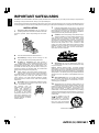
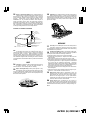
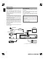
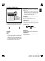
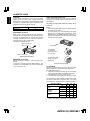
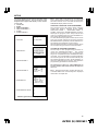
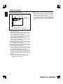
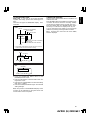
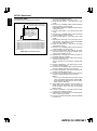
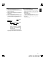
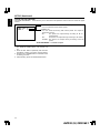
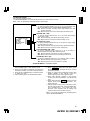
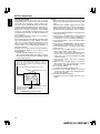
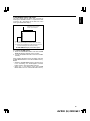
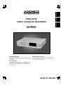
ENGLISH FRANÇAIS ESPAÑOL TIMELAPSE VIDEO CASSETTE RECORDER NEDERLANDS ESPAÑOL ITALIANO AVR30 Instruction manual Manual de instrucciones To obtain the best performance and ensure years of trouble-free use, please read this instruction manual completely. Para obtener el mejor funcionamiento y asegurar años de uso libre de problems, lea cuidadosamente este manual de instrucciones. Mode d’emploi Des performances optimales et un fonctionnement à long terme seront assurés en appliquant les présentes instructions après avoir entièrement lu ce mode d’emploi. AVR30 (E) QR33651 ENGLISH FEATURES CONTENTS Recording • High Density Time-Lapse Video Recorder • Three Touch-Selectable Recording Speeds (06, 18, 30) • Automatic “Alarm-Command” Speed up • Recording Check • On-Screen and On-Tape Time/Date Information • 7-Day Programmable On/Off Timer • “Alarm On” Output • Usable Audio at 06, A18 and A30 Hour Speeds FOR YOUR SAFETY ...................................................2 PRECAUTIONS...........................................................2 IMPORTANT SAFEGUARDS .....................................3 CONTROLS AND FUNCTIONS .................................5 INSTALLATION ..........................................................9 EXTERNAL CONNECTIONS....................................10 CASSETTE TAPES ...................................................11 SETUP .......................................................................12 SETTING THE TIME AND DATE..........................13 SETTING [OPTIONS] ITEMS ...............................14 SUMMER TIME FUNCTION ................................14 SETTING THE TIMER ...........................................15 SETTING THE VCR FUNCTIONS ........................17 SETTING THE BUZZER ........................................18 SETTING THE ALARM .........................................19 ALARM MEMORY RECALL AND RESET............20 OPERATION..............................................................21 TAPE RECORDING ...............................................21 REC CHECK ...........................................................21 AUTO REC CHECK ...............................................21 TIMER RECORDING .............................................21 TAPE RECYCLE.....................................................22 ALARM RECORDING ...........................................22 MASTER SYSTEM RESET ...................................22 PLAYBACK ............................................................22 STILL PLAYBACK .................................................23 V.LOCK ADJUST ..................................................23 PLAYBACK IN THE FIELD ADVANCE/REVERSE MODES.........................23 VISUAL SEARCH (High Speed Scan) .................23 ALARM INDEX SEARCH ......................................23 TO SECURE THE VCR ..........................................23 PROBLEM GUIDE.....................................................24 SPECIFICATIONS .....................................................25 Playback • Time-of-Alarm Memory and Alarm Index Search • High Speed Visual Search • Four Playback Speeds (06, A18, A30, 30) • Still Field, Field-Advance, Field-Reverse and Reverse Playback Security • About 720 Hours Memory Protection • Electronic Security Lockout Note: This recorder has a rechargeable battery to maintain display functions and recording mode within 720 hours in the event of power loss. When the recorder is received, the unit must be connected to power source for 48 hours to assure the battery has been adequately charged. Auto Head Cleaning System This system cleans the video heads automatically when a cassette is inserted and ejected or the tape is rewound in the recycle recording mode, to prevent dirt from accumulating on the heads. Touches the video head in the active position Cylinder ; ;; Cleaning roller in the stand-by position (Special material) Tape guide Video head Tape 1 AVR30 (E) QR33651 PRECAUTIONS Power supply: AC 120V, 60 Hz only If the unit is to be left unattended for a log period and it is not intended to use the unit, it is recommended that the unit be completely switched off by removing the plug. Safety • Should any solid object or liquid fall into the cabinet, turn off the unit and have it checked by qualified personnel before operating it any further. • To disconnect the power cord, pull it out by the plug. Never pull the cord itself. Illustrated below is molded on the back of your unit. CAUTION ATTENTION RISK OF ELECTRIC SHOCK DO NOT OPEN RISQUE DE CHOC ELECTRIQUE NE PAS OUVRIR This symbol warns the user that uninsulated voltage within the unit may have sufficient magnitude to cause electric shock. Therefore, it is dangerous to make any kind of contact with any inside part of this unit. This symbol alerts the user that important literature concerning the operation and maintenance of this unit has been included. Therefore, it should be read carefully in order to avoid any problems. CAUTION: TO REDUCE THE RISK OF ELECTRIC SHOCK, DO NOT REMOVE COVER (OR BACK). NO USER–SERVICEABLE PARTS INSIDE. REFER SERVICING TO QUALIFIED SERVICE PERSONNEL. WARNING: TO PREVENT FIRE OR ELECTRIC SHOCK, DO NOT EXPOSE THIS APPLIANCE TO RAIN OR MOISTURE. Warning: This equipment has been tested and found to comply with the limits for a Class A digital device, pursuant to Part 15 of the FCC Rules. These limits are designed to provide reasonable protection against harmful interference when the equipment is operated in a commercial environment. This equipment generates, uses, and can radiate radio frequency and, if not installed and used in accordance with the instruction manual, may cause harmful interference to radio communications. Operation of this equipment in a residential area is likely to cause harmful interference in which case the user will be required to correct the interference at his own expense. CAUTION: CHANGES OR MODIFICATIONS NOT EXPRESSLY APPROVED BY THE PARTY RESPONSIBLE FOR COMPLIANCE COULD VOID THE USER’S AUTHORITY TO OPERATE THE EQUIPMENT. ENGLISH FOR YOUR SAFETY Installation • Choose a location in which air can pass through the ventilation holes in the bottom, top and back of the unit to prevent it from overheating. • Do not install the unit near sources such as radiators or air ducts or in a place subject to direct sunlight, excessive dust, mechanical vibrations or shock. • Do not place heavy objects or heat-generating objects on the VCR, or the cabinet could be damaged or the temperature inside the VCR could rise, which could cause a fault. • Never bring a magnet or magnetized object near the VCR because it will adversely affect the performance of the VCR. • Do not install the unit in an inclined position. The unit is designed for operation in a horizontal position. Operation • Condensation If you pour a cold liquid into a glass, water vapor in the air will condense on the surface of glass. This is the condensation of moisture. Condensation on the head drum, one of the most crucial parts of the VCR, will cause damage to the tape. The VCR should not be operated for at least 2 hours after being moved from a cold to a hot environment to avoid condensation from occurring on the head drum. Cleaning • Be careful; when surface of the case is wiped with a volatile agent such as benzine, alcohol, thinner, etc., or a chemically processed cloth, the surface finish may be degraded or its coating may peel off. Repacking • It is wise to save the packing materials and box in case you ever need to ship or store your unit. This digital apparatus does not exceed the Class A limits for radio noise emissions from digital apparatus as set out in the Interference-causing equipment standard entitled “Digital Apparatus”, ICES003 of the Department of Communications. 2 AVR30 (E) QR33651 ENGLISH IMPORTANT SAFEGUARDS In addition to the careful attention devoted to quality standards in the manufacture of your video product, safety is a major factor in the design of every instrument. But, safety is your responsibility too. These pages list important information that will help to assure your enjoyment and proper use of a Video Cassette Recorder and accessory equipment. Please read it carefully before operating your video product and keep it in a handy place for future reference. INSTALLATION 1 Read and Follow Instructions—All the safety and operating instructions should be read before the video product is operated. Follow all operating and use instructions. 7 Power-Cord Protection—Power-supply cords should be routed so that they are not likely to be walked on or pinched by items placed upon or against them, paying particular attention to cords at plugs, convenience receptacles, and the point where they exit from the appliance. 8 Ventilation—Slots and openings in the cabinet are provided for ventilation to ensure reliable operation of the video product and to protect it from overheating. These openings must not be blocked or covered. The openings should never be blocked by placing the video product on a bed, sofa, rug, or other similar surface. This video product should never be placed near or over a radiator or heat register. This video product should not be placed in a built-in installation such as a bookcase or rack unless proper ventilation is provided or the video product manufacturer’s instructions have been followed. Power Sources—This video product should be operated only from the type of power source indicated on the marking label. If you are not sure of the type of power supply to your home, consult your video dealer or local power company. For video products intended to operate from battery power, or other sources, refer to the operating instructions. 6 Overloading—Do not overload wall outlets and extension cords as this can result in a risk of fire or electric shock. Overloaded AC outlets and extension cords are dangerous, and so are frayed power cords, damaged or cracked wire insulation and broken plugs. They may result in a shock or fire hazard. Periodically examine the cord and have it replaced by your service technician if appearance indicates damage or deteriorated insulation. hirayamo akiko sasaki akemi horie youji setuko kimio Zoo Docter Part 1 mito Zoo Docter Part 2 yakamashii Why? mitono igarashi kuro abcdfevcdsz 5 kabushiki auto moter mitoniikikata Grounding or Polarization—This video product is equipped with a 3-wire grounding-type plug, a plug having a third (grounding) pin. This plug will only fit into a grounding-type power outlet. This is a safety feature. If you are unable to insert the plug into the outlet, contact your electrician to replace your obsolete outlet. Do not defeat the safety purpose of the grounding-type plug. album kakurai kusano tadashiigenkou oomori tadashiigenkou matuda mother diet funga funga funga funga funga ga funga fun Head Warnings—Comply with all warnings on the video product and in the operating instructions. 4 mekoalbum yohsinarishashin mito 3 key to chise yohsinarish nurie MOMO namemekogaikiteita Retain Instructions—The safety and operating instructions should be retained for future reference. momogatoiredemizubitashi 2 kawaii koneko cat book chise 1 chise 2 chise 3 chise 4 chise 5 key 1 key 2 key 3 key 4 key 5 ebisu 1 ebisu 2 momo 1 momo 2 momo 3 tomodachi junkaikun nyanko 2 1 3 okubyo midori 2 3 mother metsuki mame 1 Part2 123 9 Attachments—Do not use attachments unless recommended by the video product manufacturer as they may cause hazards. Caution: Maintain electrical safety. Powerline operated equipment or accessories connected to this unit should bear the UL listing mark or CSA certification mark on the accessory itself and should not have been modified so as to defeat the safety features. This will help avoid any potential hazard from electric shock or fire. If in doubt, contact qualified service personnel. 10 Water and Moisture—Do not use this video product near water—for example, near a bath tub, wash bowl, kitchen sink, or laundry tub, in a wet basement, or near a swimming pool, and the like. 11 Accessories—Do not place this video product on an unstable cart, stand, tripod, bracket, or table. The video product may fall, causing serious injury to a child or adult, and serious damage to the appliance. Use only with a cart, stand, tripod, bracket, or table recommended by the manufacturer, or sold with the video product. Any mounting of the product should follow the manufacturer’s instructions, and should use a mounting accessory recommended by the manufacturer. appliance and cart 11A An combination should be moved with care. Quick stops, excessive force, and uneven surfaces may cause the appliance and cart combination to overturn. (Continued on other side) 3 AVR30 (E) QR33651 Outdoor Antenna Grounding—If an outside antenna or cable system is connected to the video product, be sure the antenna or cable system is grounded so as to provide some protection against voltage surges and built-up static charges. Section 810 of the National Electrical Code, ANSI/NFPA No. 70, provides information with respect to proper grounding of the mast and supporting structure, grounding of the lead-in wire to an antenna discharge unit, size of grounding conductors, location of antenna-discharge unit, connection to grounding electrodes, and requirements for the grounding electrode. See example below. 16 Lightning—For added protection for this video product during a lightning storm, or when it is left unattended and unused for long periods of time, unplug it from the wall outlet and disconnect the antenna or cable-system. This will prevent damage to the video product due to lightning and power-line surges. ENGLISH 12 EXAMPLE OF ANTENNA GROUNDING ANTENNA LEAD IN WIRE GROUND CLAMP ANTENNA DISCHARGE UNIT (NEC SECTION 810-20) GROUNDING CONDUCTORS (NEC SECTION 810-21) SERVICE GROUND CLAMPS ELECTRIC SERVICE EQUIPMENT POWER SERVICE GROUNDING ELECTRODE SYSTEM (NEC ART 250, PART H) NEC — NATIONAL ELECTRICAL CODE 13 Power Lines—An outside antenna system should not be located in the vicinity of overhead power lines or other electric light or power circuits, or where it can fall into such power lines or circuits. When installing an outside antenna system, extreme care should be taken to keep from touching or approaching such power lines or circuits as contact with them might be fatal. Installing an outdoor antenna can be hazardous and should be left to a professional antenna installer. USE 14 Cleaning—Unplug this video product from the wall outlet before cleaning. Do not use liquid cleaners or aerosol cleaners. Use a damp cloth for cleaning. 15 Object and Liquid Entry—Never push objects of any kind into this video product through openings as they may touch dangerous voltage points or short-out parts that could result in a fire or electric shock. Never spill liquid of any kind on the video product. 17 Servicing—Do not attempt to service this video product yourself as opening or removing covers may expose you to dangerous voltage or other hazards. Refer all servicing to qualified service personnel. 18 Conditions Requiring Service—Unplug this video product from the wall outlet and refer servicing to qualified service personnel under the following conditions. a. When the power-supply cord or plug is damaged. b. If liquid has been spilled, or objects have fallen into the video product. c. If the video product has been exposed to rain or water. d. If the video product does not operate normally by following the operating instructions. Adjust only those controls that are covered by the operating instructions. Improper adjustment of other controls may result in damage and will often require extensive work by a qualified technician to restore the video product to its normal operation. e. If the video product has been dropped or the cabinet has been damaged. f. When the video product exhibits a distinct change in performance — this indicates a need for service. 19 Replacement Parts—When replacement parts are required, have the service technician verify that the replacements he uses have the same safety characteristics as the original parts. Use of replacements specified by the video product manufacturer can prevent fire, electric shock or other hazards. 20 Safety Check—Upon completion of any service or repairs to this video product, ask the service technician to perform safety checks recommended by the manufacturer to determine that the video product is in safe operating condition. 4 AVR30 (E) QR33651 ENGLISH CONTROLS AND FUNCTIONS [FRONT] 1 2 DISPLAY (See page 7) S 3 4 5 6 7 8 9 10 11 12 13 14 15 1. RESET BUTTONS Press these buttons at the same time to clear all (microprocessor) functions. Press the “S” button to reset the system. (This does not erase the stored information.) 2. CASSETTE COMPARTMENT 3. SHARPNESS CONTROL Adjust the picture quality to hard or soft during playback. 4. TRACKING CONTROL Adjust to optimize the picture quality during playback at the 06, A18 and A30 hour speeds. 5. SLOW TRACKING CONTROL Adjust to optimize the picture quality in the SLOW PLAY mode, e.g. speed 30 hours of field advance/reverse mode. 6. V. LOCK CONTROL 16 17 18 11. UP BUTTON Press to increase, change or advance to the next higher value. 12. V-POS (VERTICAL POSITION) BUTTON Press repeatedly to control the vertical position of the programmable display on the monitor. 13. H-POS (HORIZONTAL POSITION) BUTTON Press repeatedly to control the horizontal position of the programmable display on the monitor. 14. ALARM INDEX BUTTON Press this button to cause the INDEX indicator to light, and set the VCR to the visual search mode (press F.FWD or REWIND during playback mode) in this state; the start of the alarm recorded can be located. 15. ALARM RESET BUTTON Press to clear POWER LOSS information. When this button is pressed when the ALARM MEMORY screen is being displayed, the alarm memory is cleared. Reduces vertical jitter in the still play mode. 16. COUNTER RESET BUTTON 7. PROGRAM BUTTON Press to select one of the six programmable functions. Press to clear the digital counter to “00000”. 17. REC/PLAY HOURS BUTTONS ▲ (UP): 8. START/STOP BUTTON Press to start or stop the programming of a programmable function. (Press once to start the programming sequence and a second time to stop (end) it.) 9. SET BUTTON Press to select the specific value which is to be changed with the UP/DOWN buttons. 10. DOWN BUTTON Press to increase hours to the next higher value. ▼ (DOWN): Press to decrease hours to the next lower value. The tape speed will be indicated as part of the monitor display. 18. TIMER BUTTON Press after programming the TIMER for automatic TIMER recording. See page 15 for TIMER programming. Press to decrement, change or reverse to the previous/lower value. 5 AVR30 (E) QR33651 ENGLISH 19 20 21 22 28 27 26 23 19. EJECT BUTTON Press to remove the cassette. The EJECT button will not operate in the RECORD mode. 20. FIELD REVERSE BUTTON Press to reverse the tape by one field in the STILL playback mode. 24 25 26. REVERSE PLAY BUTTON Press to play recorded material at the 06 speed in the reverse direction during the PLAY mode. 27. FAST FORWARD/VISUAL SEARCH BUTTON Press to activate fast forward. Press this button during playback and a forward playback picture at high speed can be seen. 21. STILL BUTTON Press to momentarily stop tape motion in the play mode. The STILL function allows close inspection of individual scenes. See the description of STILL playback on page 23. 28. REWIND/VISUAL SEARCH BUTTON Press to start rewind. Press this button during playback and a reverse playback picture at high speed can be seen. 22. FIELD ADVANCE BUTTON Press to advance the tape one field in the STILL playback mode. Also, used for summer time setting. See “SUMMER TIME FUNCTION” on page 14 for details. 23. RECORD BUTTON Press to start recording. 24. STOP BUTTON Press to stop the tape. The STOP button must be pressed to end the RECORD and PLAY mode. 25. PLAY BUTTON Press to play recorded material in the forward direction. Pressing this during recording makes it possible to check recordings. 6 AVR30 (E) QR33651 ENGLISH CONTROLS AND FUNCTIONS (Continued) [DISPLAY] 29 30 31 32 TAB ALARM TAPE END REC 36 INDEX 33 34 35 LOCK A 37 29. TAPE-IN INDICATOR Lights when a cassette is in the compartment. 30. TAB INDICATOR Lights when a cassette without its safety tab is loaded. 31. ALARM INDICATOR ALARM appears during alarm recording. ALARM flashes when alarm recording ends. 32. TAPE END INDICATOR Lights when the tape reaches the end during recording. Note: “TAPE END” is not displayed when you have selected REWIND, RE-REC in the “RECYCLE FUNCTIONS” menu in the alarm display or you have selected REWIND, STOP IF ALARM but an alarm recording has not been made. 33. A INDICATOR Lights when no video signal is input. Video signal input will turn this indicator off automatically. 34. TIMER INDICATOR This is lit during timer recording or TIMER stand-by mode. The indicator flashes in the following cases. • A cassette is not loaded. • A cassette without its safety tab is loaded. • The timer has not been programmed. SPEED HD TIMER 38 39 36. VCR MODE INDICATORS • • • • • • • REC tt ss tt s t ❙❙ • t❙ ❙ appears during recording. appears during the rewind mode. appears during the fast forward mode. (or ss) flashes during visual search. appears during the playback mode. appears during the reverse play mode. appears when the STILL button is pressed during play mode and disappears when the STILL or PLAY button is pressed again. (or ❙ ❙ s) appears while the FIELD REV (or FIELD ADV) is held depressed in the still playback mode. Note: Still playback is restored when the FIELD REV (or FIELD ADV) button is released. 37. INDEX INDICATOR INDEX appears when the ALARM INDEX button is pressed. INDEX disappears when the ALARM INDEX button is pressed again. INDEX flashes during alarm indexing. 38. DIGITAL COUNTER Shows the tape counter. The counter does not count during non-recorded sections of a tape. 39. TAPE SPEED INDICATOR Shows the tape speed. 35. LOCK INDICATOR LOCK appears when the recorder is in the security lock mode. 7 AVR30 (E) QR33651 40 41 42 ENGLISH [Rear] 43 44 40. VIDEO IN Receives video signal from a video camera or another VCR. 44. EXTERNAL INTERFACE (15-PIN) JACK Connect an alarm switch, door sensor, etc. using the 15-pin adapter provided. 41. VIDEO OUT For connection to monitor. iuytrewq 42. AUDIO IN Accepts an audio signal from a camera, external sound equipment or another recorder (Line: –8 dBm, 50 Kohm, unbalanced). 43. AUDIO OUT Provides an audio output for a monitor or another recorder (–9 dBm, 600 ohm, unbalanced). !5 !4 !3 !2 !1 !0 o q w e r t y u i o !0 !1 !2 !3 !4 !5 ALARM IN ALARM OUT ALARM REC RST TAPE END OUT TAPE END RST NC NC NC CAMERA SW OUT REC START IN GND NC — NC GND 8 AVR30 (E) QR33651 ENGLISH INSTALLATION VIDEO CONNECTIONS Use coaxial cables when connecting a camera and a monitor to this VCR. Note: Long cable runs to distant cameras may cause signal deterioration and/or sync discrepancies. If these problems occur, use video line amplifiers and/or cameras having phase-adjustable line-locked vertical sync. Video Input In single camera systems, connect the camera to the Video IN BNC terminal on the VCR rear panel. Use of a 2:1 interlace camera is highly recommended; otherwise, the monitor will show vertical distortion of the TIME/DATE characters. In multiple camera systems, connect the switcher output to the Video IN BNC terminal. Because multiple camera systems require synchronization, use of cameras having line-locked vertical sync or a genlocked master drive/sync source is highly recommended. The use of vertical interval switchers is also recommended. AUDIO CONNECTIONS Audio can be recorded at all speeds. To hear the playback sound, use the 06, A18 or A30 speed during playback. Audio In: Accepts an audio signal from a camera, external sound equipment, or another recorder (Line: –8 dBm, 50 kohm). Audio Out: Provides an audio output for a monitor or another recorder (–9 dBm, 600 ohm, unbalanced). USING THE 15-PIN ADAPTER Attach the wires of the alarm switch, door sensor or warning lamp to the 15-pin adapter using screws. After connection, connect the adapter to the EXTERNAL INTERFACE jack on the rear of the VCR. See page 10 for details. Video Output Connect the monitor to the Video OUT BNC terminal on the rear panel. MONITOR MICROPHONE PREAMP VIDEO CAMERA/RECORDER CAMERA SWITCHER 15-PIN ADAPTER (provided) * It is necessary to connect to suit your purpose. 9 AVR30 (E) QR33651 Pin Arrangement of 15-Pin Adapter 11 10 9 5 4 3 2 1 q ALARM IN w ALARM OUT e ALARM REC RST r TAPE END OUT t TAPE END RST o CAMERA SW OUT !0 REC START IN !1 GND ALARM IN You can connect an alarm switch with a resistance of 1 kohm or less or a door sensor. Connect pin q to pin !1(ground) through the switches. ALARM IN GND q !1 TAPE END OUT Approx. 12V is applied to pin r when the tape reaches the end. Notes: • This does not operate when you have selected “REWIND, RE-REC” in the “RECYCLE FUNCTIONS” menu in the ALARM SET display or you have selected “REWIND, STOP IF ALARM” and no alarm recording has been made. • The output impedance is approx. 100 ohm. ENGLISH EXTERNAL CONNECTIONS TAPE END RST The TAPE END OUT function can be turned off when pin t is shorted to pin !1. Note: Do not apply a voltage to pin t or !1. CAMERA SW OUT Pin o outputs the following signal each time a onefield image is recorded. You can combine this with a video camera switcher which can be controlled externally. The output timing can be specified using the SELECTION MENU screen. 4.5~5.5V 0~0.4V 5±2ms Note: Do not apply a voltage to pin q or !1. ALARM OUT Approx. 12V is applied to pin w during an alarm recording. Notes: • When you have selected “PULSE” in the “ALARM OUT” menu in the ALARM SET display, approx. 12V pulses will be applied to the output after the alarm recording ends. • When you have selected “DURATION” in the “ALARM OUT” menu in the ALARM SET display, no voltage is applied after the alarm recording ends. • The output impedance is approx. 100 ohm. REC START IN Recording is started when 5-12V is applied to pin !0. ALARM REC RST When pin e is shorted to pin !1 during alarm recording, alarm recording is stopped and the original mode be restored. 10 AVR30 (E) QR33651 ENGLISH CASSETTE TAPES TAPE LIFE Slower speed operation in time lapse recording applies stress to video tape. Tapes should be inspected and, if necessary, discarded after the total number of complete tape passes (recording and playback) exceeds the following limits: Tape Speed 06, 18, 30 Complete Tape Passes 25 INSERTING A CASSETTE Note: This is the first step in all VCR operations. The VCR will not operate without a cassette in place. To insert a cassette push the cassette through the cassette compartment door until the VCR mechanism pulls it into the compartment. The tape-in indicator turns on. TOP OF CASSETTE (THIS SIDE UP) VIDEO CASSETTE SAFETY TAB To prevent accidental erasure of recorded material, remove the safety tab from the lower left corner of the cassette. Recording is impossible when the safety tab is removed. Notes: • The TAB indicator lights when a cassette without its safety tab is loaded. • To record again on a cassette that has its safety tab removed, cover the tab hole with tape. In the TIMER mode, the TIMER indicator will flash on and off if the cassette is inserted without its safety tab slot covered or intact. SAFETY TAB INSE RT TO PREVENT ACCIDENTAL ERASURE, BREAK OFF THE TAB SAFETY TAB SLOT Tape Insertion Position REMOVING A CASSETTE Before removing a cassette, rewind the tape completely. To remove a cassette, press the EJECT button. The cassette will come partially out of the compartment so you can pull it out. TO RECORD AGAIN, COVER THE HOLE WITH TAPE Video Cassette Safety Tab TAPE LENGTH The total recording time at each of the three tape speeds depends on the length of the tape used. The table below shows: 1. The total recording time that can be recorded at each tape speed mode on T60 and T120 tapes. 2. The pictures per second at each speed. 3. The speeds at which audio can also be recorded. Use the table to select the tape length which gives the best compromise between tape cost, total recording time, and elapsed time between pictures. Tape Speed Mode Total Recording Hours Pictures/ Second Audio 06 18 30 T60 3 9 15 T120 6 18 30 RECORD 60 20 12 PLAYBACK 60 20 12 RECORD Yes Yes Yes PLAYBACK Yes YES (A18) YES(A30) Note: The values in this table are approximate. 11 AVR30 (E) QR33651 On-Screen displays are provided to aid setup of the programmable functions. The six functions on the Program Menu appear individually on the monitor in this order. 1. CLOCK SET 2. TIMER 3. SELECTION MENU 1 4. SELECTION MENU 2 5. ALARM 6. ALARM MEMORY C LOCK SET 1– 01–1999 FR I 1 2 : 00 A CLOCK SET OPT I ONS OSD TYP E : FUL L TIMER DISPLAY 1 1 2 : 00 A a 1 2 : 00 A 06 2 1 2 : 00 A a 1 2 : 00 A 06 3 1 2 : 00 A a 1 2 : 00 A 06 4 1 2 : 00 A a 1 2 : 00 A 06 5 1 2 : 00 A a 1 2 : 00 A 06 6 1 2 : 00 A a 1 2 : 00 A 06 7 1 2 : 00 A a 1 2 : 00 A 06 MON: ✽ , ✽ TUE : ✽ , ✽ WED : ✽ , ✽ THU : ✽ , ✽ FR I : ✽ , ✽ SAT : ✽ , ✽ SUN: ✽ , ✽ S ELECT I ON MENU SE ARCH SP E ED : X5 CAME RA SW : 18 ~ SELECTION MENU 1 SELECTION MENU 2 ALARM DISPLAY S ELECT I ON MENU BUZ Z E R SEL E C T I ON TAP E END : OF F TROUBL E : OFF OFF NO V I DE O : AU T O R E C CHECK : OF F A LARM OU T : OF F A L ARM DURA T I ON : SPE ED : A LARM R E ADY : A LARM OU T : Note: If the VCR is not turned on for about 720 hours after the built-in battery is fully charged (after the VCR is turned on for more than 48 hours), the TIME/DATE display will be cleared. ENGLISH SETUP SELECTING A FUNCTION TO BE PROGRAMMED The program menu will always begin with the CLOCK SET function, followed by the TIMER, SELECTION MENU 1, SELECTION MENU 2, ALARM, and then the ALARM MEMORY functions. Although the program menu always follows this order, it is possible to skip any of the available functions during the selection process. To select the desired program function (and to move from one program function to the next), press the PROGRAM button repeatedly until the desired function display format appears on the monitor. After the desired function has been selected, follow the corresponding procedure to set that function. SETTING THE PROGRAM FUNCTION(S) The first step in each programming procedure is: “Press the START/STOP button”. The system allows up to five minutes for any one function setting to be completed after the START/STOP button is pushed. If no change/setting is entered within the five minutes period, the unit will automatically exit the selected program function. (If this happens, reselect the desired program function, and follow the programming procedure for that function.) The following procedures for setting VCR functions assume that the desired function has already been selected. Note: During programming, holding the SET, UP, or DOWN button will move/change the displayed information at a rapid rate. SET MANUAL 06 YE S DURA T I ON R ECYCL E FUNC T I ONS RE W I ND , S TOP I F A LARM A LARM MEMORY A00 ALARM MEMORY DISPLAY 1 2 3 4 5 6 7 8 9 Initial Program Function Display Formats 12 AVR30 (E) QR33651 ENGLISH SETUP (Continued) SETTING THE TIME AND DATE Use the CLOCK SET display to set the date and time. TIME (HOUR, MINUTE, SECOND AM/PM) DATE (MONTH, DAY, YEAR) DAY OF WEEK: Corrected automatically to C LOCK SET match the input 1– 01–1999 FR I date. 1 2 : 00 A Notes: • Perform the same procedure as when setting the time and date to make corrections after having set them. The minutes flash on/off when the SET button is pressed (in step 2 above). • To record time and date on the tape, display them on the monitor screen. If they are not displayed on the monitor, they cannot be recorded on the tape. OPT I ONS OSD TYP E : FUL L OSD TYPE (OFF, FULL or HALF) CLOCK SET Display Format Description 1. Press the START/STOP button so that [CLOCK SET] flashes on/off. 2. Press the SET button. The day flashes on/off. 3. Press the UP or DOWN button until the desired number appears on the monitor. 4. Press the SET button. The month flashes on/off. 5. Press the UP or DOWN button until the desired number appears on the monitor. 6. Press the SET button. The year flashes on/off. 7. Press the UP or DOWN button until the desired number appears on the monitor. 8. Press the SET button. The hour flashes on/off. 9. Press the UP or DOWN button until the desired number appears on the monitor. 10. Press the SET button. The minutes flash on/off. 11. Press the UP or DOWN button until the desired number appears on the monitor. 12. Press the START/STOP button: the seconds will start counting and the clock will start. [CLOCK SET] will flash on/off again at this time. 13. To display the time/date you have set here on the monitor screen, press the START/STOP button again to cause [OPTIONS] to flash, and then proceed with step 2 in item on OSD TYPE on page 14. 14. Press the START/STOP button three times. • Make sure that letters [CLOCK SET] or [OPTIONS] are not flashing. 13 AVR30 (E) QR33651 FULL DATE POWER LOSS (IF SENSED) DAY OF WEEK ALARM COUNT* 12– 20– 1999 6 : 12 : 00P SUMMER TIME FUNCTION Set the summer time function when a cassette is not loaded in this VCR. Press the FIELD ADV and UP buttons simultaneously in modes other than the timer recording standby mode; the hour display will be counted up by one. Press the FIELD ADV and DOWN buttons simultaneously to count the hour display down by one. You can change the hour display in one-hour steps without any limit by pressing the above buttons. Note: Summer time cannot be set unless TIME/ DATE is displayed. ENGLISH SETTING [OPTIONS] ITEMS OSD TYPE: If you wish to record the time/date together with image, perform the following procedure: There are two types of TIME/DATE display: FULL and HALF. PL MON A07 06 T L SECURITY LOCK (IF ACTIVATED) TIMER (IF ON) RECORDING SPEED (IN TOTAL HOURS) TIME * The ALARM Count Number records alarms from 0 to 99 and then resets to 0 and continues counting. HALF DATE No display 12– 20– 1999 6 : 12 : 00P TIME OFF No display 1. Press the START/STOP button twice so that [OPTIONS] flashes on/off. 2. Press the SET button so that the OSD TYPE: setting flashes on/off. 3. Press the UP or DOWN button to select the setting (OFF, FULL or HALF). 4. Press the START/STOP button again. The selected setting will light. Note: The position of the TIME/DATE display on the monitor can be adjusted by using the H-POS and V-POS button on the front panel. 14 AVR30 (E) QR33651 ENGLISH SETUP (Continued) SETTING THE TIMER To set the 24 Hour On/Off Timer function. PROGRAM NUMBER TIMER RECORDING TIME START/STOP TIMER RECORDING TAPE SPEED 1 12 : 00A a 12 : 00A 06 2 12 : 00A a 12 : 00A 06 3 12 : 00A a 12 : 00A 06 4 12 : 00A a 12 : 00A 06 5 12 : 00A a 12 : 00A 06 6 12 : 00A a 12 : 00A 06 7 12 : 00A a 12 : 00A 06 MON: ✽ , ✽ TUE : ✽ , ✽ WED : ✽ , ✽ THU : ✽ , ✽ FR I : ✽ , ✽ SAT : ✽ , ✽ SUN: ✽ , ✽ DAY OF WEEK AND PROGRAM NUMBER 1 2 3 4 5 6 7 ✽ :TIMER will record for the time set for PROGRAM NUMBER 1 :TIMER will record for the time set for PROGRAM NUMBER 2 :TIMER will record for the time set for PROGRAM NUMBER 3 :TIMER will record for the time set for PROGRAM NUMBER 4 :TIMER will record for the time set for PROGRAM NUMBER 5 :TIMER will record for the time set for PROGRAM NUMBER 6 :TIMER will record for the time set for PROGRAM NUMBER 7 :No recording TIMER Display Format Description 1. Press the START/STOP button. The program number (1) flashes on/off. 2. Press the SET button. The start hours flash on/off. 3. Press the UP or DOWN button until the desired number appears on the monitor. Remember to watch the AM/PM indicator when setting the hours. 4. Press the SET button. The start minutes flash on/off. 5. Press the UP or DOWN button until the desired number appears on the monitor. 6. Press the SET button. The stop hours flash on/off. 7. Repeat steps 3 through 5 to set the stop hours and minutes. Remember to watch the AM/PM indicator when setting the hours. 8. Press the SET button. The timer recording speed flashes on/off. 9. Press the UP or DOWN button until the desired number appears on the monitor. 10. Press the SET button after setting the timer recording speed. The program number of the next lower line flashes on/off. 11. Repeat steps 2 through 9 to set the program to the other program numbers. 12. Press the SET button after setting the program numbers (1) through (7). The two program event locations of MON flash on/off. 13. Press the SET button. The first program event location of MON flashes. 14. Press the UP or DOWN button until the desired program number appears on the monitor. 15. Press the SET button. The other program event location of MON flashes on/off. 16. Press the UP or DOWN button until the desired program number appears on the monitor. Notes: • If you do not need to timer record two events a day, mark either event with an asterisk (✽). • If two asterisks are displayed, no timer recording is made on that day. 17. After setting two program event locations of MON, press the SET button. The two program event locations of the next day of the week flashes on/off. 18. Press the SET button. The first program event location of the next day flashes. 19. Repeat steps 12 through 16 to set the program event locations up to SUN. 20. Press the START/STOP button when the TIMER has been set. 15 AVR30 (E) QR33651 ;; ;; ;;; ;; ;;; ■ To correct information 1. Press the START/STOP button. 2. Press the UP or DOWN button repeatedly until the item to be corrected (Program number or program event location of day of the week) flashes on/off. 3. When the section to be corrected flashes on/off, press the SET button. • Press the SET button again so that only the digit to be corrected flashes on/off. 4. Press the UP or DOWN button to correct the set information. 5. After completing the correction, press the START/STOP button. ENGLISH Notes: 1. Programming the TIMER function does not activate it. See TIMER recording, page 21. 2. To record the time and date press the PROGRAM button to display them. 3. When the preset START time is later than the STOP time, the recording will be made into the following day. 4. When the START time and STOP time are the same, a recording will not be made. 5. When the programs for timer recording overlap each other, recording will be switched to the program with the later recording start time. Example ••••• Record Program number 1 Program number 2 Time Program number 3 When recording of program number 3 is terminated, program number 2 will be recorded for its remaining time. 6. When two programs have the same start time, the program number with the longest stop time has priority. 16 AVR30 (E) QR33651 ENGLISH SETUP (Continued) SETTING THE VCR FUNCTIONS The SELECTION MENU 1 screen allows you to select the VCR operations and functions to match the applications. S ELECT I ON MENU SE ARCH SP E ED : X5 CAME RA SW : 18 ~ SEARCH SPEED (3, 5, 7 or 9 times the normal speed) • You can select the visual search speed. CAMERA SW • You can select the timing with which pulses are output to switch the camera. • 18~: The pulses are output during recording at 18 or a longer speed. ALL: The pulses are output during recording in all modes. 06 ONLY: The pulses are output during recording at the 06 speed. SELECTION MENU 1 Format Description 1. Press the START/STOP button. The SEARCH SPEED option “X5” flashes on/ off. 2. Press the SET button repeatedly until the item the setting of which you want to change flashes. 3. Press the UP or DOWN button to select the value or setting you want. 4. After selecting, press the START/STOP button. 17 AVR30 (E) QR33651 ENGLISH SETTING THE BUZZER This VCR has a buzzer function. Use SELECTION MENU 2 to select the times when you wish buzzer to sound. Note: “OFF” is specified for all buzzer options at the factory. TAPE END (ON or OFF) • To specify whether buzzer turns on or off, synchronized with pin r TAPE END OUT of the EXTERNAL INTERFACE jack. ON: Buzzer will keep sounding when tape reaches the end during recording. OFF: Buzzer will not sound even when tape reaches the end. S ELECT I ON MENU BUZ Z E R SEL E C T I ON TAP E END : OF F TROUBL E : OFF OFF NO V I DE O : AU T O R E C CHECK : OF F A LARM OU T : OF F TROUBLE (ON or OFF) • To specify whether buzzer turns on or off when abnormality occurs in this VCR. ON: Buzzer will keep sounding if abnormality occurs. OFF: Buzzer will not sound even if abnormality occurs. NO VIDEO (ON or OFF) • To specify whether buzzer turns on or off when no video signal is input during recording. ON: Buzzer will keep sounding when video signal input stops. OFF: Buzzer will not sound even when input stops. AUTO REC CHECK (ON or OFF) • To specify whether buzzer turns on or off if recording is abnormal after the AUTO REC CHECK function. ON: Buzzer will keep sounding if recording is abnormal. OFF: Buzzer will not sound even if recording is abnormal. ALARM OUT (ON or OFF) • To specify whether buzzer turns on or off when alarm is output. ON: Buzzer will keep sounding if alarm is output. OFF: Buzzer will not sound even if alarm is output. SELECTION MENU 2 Format Description 1. Press the START/STOP button. The TAPE END option “OFF” flashes on/off. 2. Press the SET button repeatedly until the item the setting of which you want to change flashes. 3. Press the UP or DOWN button to select the value or setting you want. 4. After selecting, press the START/STOP button. To stop buzzer: 1. When TAPE END lights in the VCR display, press the EJECT button: The tape will come out and the buzzer will stop. 2. When “A” lights in the VCR display and also “NO VIDEO” appears on the monitor screen, the buzzer will stop when video signal is input. 3. When “REC CHECK” appears on the monitor screen, press the STOP button: The buzzer will stop. 4. When alarm indicator ALARM flashes in the VCR display, press the ALARM RESET button: The buzzer will stop. 5. If buzzer function varies in any of the above cases, the VCR may be abnormal. Press the RESET buttons simultaneously: The buzzer will stop. However, note carefully that all settings will return to initial values set at the factory. Note: You can also stop buzzer by switching ON to OFF in SELECTION MENU 2. 18 AVR30 (E) QR33651 ENGLISH SETUP (Continued) SETTING THE ALARM The ALARM function allows the user to set the recording duration, speed to be recorded and tape recycle for alarm recordings. When a contact closure occurs at the ALARM IN input, the VCR automatically enters the RECORD mode at the pre-programmed ALARM recording speed. (See Alarm In, page 10 for a complete description of the ALARM sequence.) The ALARM recording duration can last according to the set value, or until the contact closure is reopened. The ALARM recording speed can be pre-programmed to 06, 18 or 30. The checking signal is automatically recorded on the tape at the beginning of each ALARM recording. Later, you can easily locate the start of each recording by using these signals when watching a recorded content. See “ALARM INDEX SEARCH” on page 23 for details. See page 14 if you also want to record the date/time. The TIME/DATE display is set as follows during ALARM display. — ALARM stars (✽) will replace the colons (:). — The recording speed will be changed to 06, 18 or 30 which was selected from the “SPEED” setting in the ALARM display. DURATION: User programmable length or time the unit stays in the alarm record mode. (MANUAL, 5 SEC, 15 SEC, 30 SEC, 1 MIN, 3 MIN, 5 MIN, 10 MIN, 30 MIN, 60 MIN or TAPE END) ALARM RECORDING TAPE SPEED (06, 18 or 30) ALARM READY (YES or NO) A L ARM DURA T I ON : SPE ED : A LARM R E ADY : A LARM OU T : SET MANUAL 06 YE S DURA T I ON Notes: • When the ALARM recording ends, the VCR will return to the status it was in before the alarm was input. • Select 06 at the “SPEED” setting when the alarm input is within 30 seconds. If the 18 or 30 speed is selected, electronic “marks” are not recorded on the tape and alarm index search will not operate. 1. Press the START/STOP button. The duration setting flashes on/off. 2. Press the UP or DOWN button until the desired setting appears on the monitor. (MANUAL, 5, 15, 30 SEC, 1, 3, 5, 10, 30, 60 MIN, TAPE END) 3. Press the SET button. The record speed setting flashes on/off. 4. Press the UP or DOWN button until the desired setting appears on the monitor. (06, 18 or 30) 5. Press the SET button. The alarm ready setting flashes on/off. 6. Press the UP or DOWN button to select the alarm ready function. (YES or NO) Select “YES” if you want to start alarm recording even in the normal record or stop mode. Select “NO” if you do not want alarm recording in the stop mode. 7. Press the SET button. The alarm out setting flashes on/off. 8. Press the UP or DOWN button to select the alarm out function. See “ALARM OUT” on page 10 for details. (DURATION or PULSE) 9. Press the SET button. The RECYCLE position flashes on/off. 10. Press the UP or DOWN button to select the mode at the end of tape. See “TAPE RECYCLE” on page 22 for details. 11. Press the START/STOP button. Programming for the ALARM has been completed. R ECYCL E FUNC T I ONS RE W I ND , S TOP I F A LARM ALARM OUT (DURATION or PULSE) RECYCLE FUNCTIONS (“REWIND, STOP IF ALARM”, “REWIND, STOP” or “REWIND, RE-REC”) ALARM Display Format Description 19 AVR30 (E) QR33651 ENGLISH ALARM MEMORY RECALL AND RESET The VCR signals that an alarm has occurred by flashing the ALARM indicator. If a power loss has occurred, “PL” will appear in the first line of the FULL type TIME/DATE display. ALARM COUNT : Displays the number of alarm inputs that have occurred. Counts up to 99 inputs. A LARM MEMORY A00 1 2 3 4 5 6 7 8 9 ALARM MEMORY: 1: Displays the date/time of the first alarm recording. 2~9: Displays the 8 dates/times of the last alarms to have occurred including the last alarm recording. ALARM MEMORY Display Format Description To recall the ALARM display: 1. Press the PROGRAM button until the ALARM MEMORY display appears on the monitor. 2. Log the time/date information from the ALARM memory. After checking the alarm times and dates, press the ALARM RESET button to clear the ALARM memory. Notes: • When the ALARM RESET button is pressed once, if “PL” is flashing, “PL” will disappear. Press the button again to clear the ALARM memory. • When “PL” is not flashing, press the ALARM RESET button once to clear the ALARM memory. 20 AVR30 (E) QR33651 ENGLISH OPERATION TAPE RECORDING CAUTION: Recording over existing recorded material will completely erase that material. To prevent accidental recording over the end of a previous recording, advance the tape several seconds before beginning the next recording. 1. Insert a video cassette; be sure the cassette safety tab is intact, or the tab slot is covered. 2. Press the REC/PLAY HOURS button until the desired tape speed is observed on the tape speed indicator. 3. Press the RECORD button to start recording. 4. Press the STOP button to stop recording. Notes: — The tape speed mode can be changed during recording. — AUDIO can be recorded at the 06, 18 or 30 tape speed. — “NO VIDEO” will be displayed when no NO V I DEO video signal input during recording. TIMER RECORDING This VCR can also record at any speed on TIMER command (turn on/off to record during any 24-hour time period). To program the TIMER function, refer to pages 15 and 16. To operate the TIMER recording function; follow the TAPE RECORDING procedure, step 1, then press the TIMER button to activate the programmed TIMER function. This VCR offers two special recording functions, TIMER recording and ALARM recording. REC CHECK This function allows you to check whether the pictures are being recorded normally or not during recording. When the PLAY button is pressed during recording, the recorded picture is played back for several seconds. Then recording will continue. AUTO REC CHECK If tape reaches the end during recording, this function allows the VCR to automatically rewind the tape and play it back for several seconds. If AUTO REC CHECK detects from playback that the tape has been normally recorded, the VCR will rewind the tape to its start. If AUTO REC CHECK detects that the tape has not been normally recorded, “REC CHECK” will appear at the top left of the monitor screen. Note: If “AUTO REC CHECK: ON” is specified in SELECTION MENU 2, the buzzer will keep sounding when tape has not been normally recorded. 21 AVR30 (E) QR33651 Recycle REWIND, STOP IF ALARM Alarms Present on Recorded Tape When “REWIND, STOP” is selected: — When the tape reaches the end during recording, the VCR automatically rewinds to the beginning of tape and enters the STOP mode. When “REWIND, RE-REC” is selected: — When the tape reaches the end during recording, the VCR automatically rewinds to the beginning of tape and continues recording. ENGLISH TAPE RECYCLE The “RECYCLE FUNCTIONS” in the ALARM SET display determine the mode after recording at the end of tape. When the “REWIND, STOP IF ALARM” is selected: — If no alarm has been received during the recorded period, the VCR automatically rewinds to the beginning of tape and continues recording. — If an alarm has been received via the ALARM IN terminal during the recording period, the VCR automatically rewinds to the beginning of tape and then enters the STOP mode. Note: When “REWIND, STOP” or “REWIND, REREC” is selected, the VCR operates whether an alarm has occurred or not. Results YES Rewinds tape, then stops. Will not respond to alarm input. NO Rewinds tape then continues to record. YES Rewinds tape, then stops. Will not respond to alarm input. NO Rewinds tape, then stops. Will not respond to alarm input. YES Rewinds tape then continues to record. NO Rewinds tape then continues to record. REWIND, STOP REWIND, RE-REC ALARM RECORDING This VCR can automatically record at one of three speeds 06, 18 or 30 when an alarm command is given. To program the ALARM function refer to page 19. The remote/contact switch must be connected to the VCR. See page 10. To operate the ALARM recording in the stop mode; follow the TAPE RECORDING procedure, step 1, then select “YES” of the ALARM READY menu in the ALARM SET display. MASTER SYSTEM RESET Press the two reset buttons simultaneously to provide a MASTER SYSTEM RESET. Use to reset abnormal displays and operations. The programmable features must be re-programmed. PLAYBACK 1. Rewind the tape to the desired beginning point. (Press the REWIND button, and observe the digital counter until the desired number appears.) Press the stop button. 2. Press the REC/PLAY HOURS button until the desired tape speed is observed on the tape speed indicator. 3. Press the PLAY button to initiate forward playback. To select reverse playback; press the PLAY button and then press the REVERSE PLAY button. Forward playback resumes when the PLAY button is pressed. Notes: • When the REVERSE PLAY button is pressed in the forward playback mode to set the VCR to the reverse playback mode, the first several frame images may be distorted. • The VCR will automatically enter the STOP mode if the reverse play is continued for approx. 1 minute. 4. Press the STOP button to stop playback. Notes: — The tape speed mode can be changed during playback. — When a picture recorded in the 06 mode is played back in the A18 or A30 mode, it includes noise. It is recommended that you play back pictures recorded in the 06 mode at modes 06 or 30. — When the tape reaches the end, the unit automatically rewinds to the beginning of the tape and then goes to the STOP mode. — If the monitor display exhibits distortion in the upper part of the picture, adjust the horizontal hold control on the monitor. — Adjust the SLOW TRACKING control to minimize noise when playing back at slow speed (30 Hr or FIELD ADVANCE/REVERSE). 22 AVR30 (E) QR33651 ENGLISH OPERATION (Continued) STILL PLAYBACK When the STILL button is pressed during playback, a still picture can be seen. To start again press STILL or PLAY button and the VCR will continue playback. Notes: • When still playback continues for more than 5 minutes, the AUTO-PROTECT circuit operates and the VCR will enter the STOP mode automatically. • If the picture shakes up and down during still playback, adjust the V.LOCK control. V.LOCK ADJUST If the picture shakes up and down during still playback, adjust the picture by the following procedure. 1. Play back a tape, recorded in the 06 mode, in the still playback mode. • With some TVs, if the V.LOCK control is adjusted when playing a tape recorded in modes other than 06, shaking of the still picture may not stop. 2. Adjust the V.LOCK control so the shaking of the picture stops. Note: Shaking of the picture may not be stopped completely depending on the TV used. PLAYBACK IN THE FIELD ADVANCE/REVERSE MODES When you press the FIELD ADVANCE or FIELD REVERSE button during still playback mode, one field at a time can be seen. Operates only after STILL button has been pressed. Notes: • An AUTO-PROTECT circuit automatically returns the unit to the STOP mode if the STILL or PLAY button is not pressed again or if FIELD ADVANCE or FIELD REVERSE button is not pressed in any five minute period. • When the FIELD REVERSE button is pressed in the still playback mode to set the VCR to the field reverse mode, the first several frame images may be distorted. VISUAL SEARCH (High Speed Scan) Note: The visual search function allows the recorded material to be reviewed at 3, 5, 7 or 9 times the 06 hour speed mode. 1. Press the PLAY button. 2. Press the SEARCH (F.FWD) button to select the VISUAL SEARCH FORWARD mode, or press the SEARCH (REWIND) button to select the VISUAL SEARCH REVERSE mode. 3. Press the PLAY button again to resume normal playback. Notes: • The visual search speed can be changed using the SELECTION MENU screen. • The playback picture will have some noise in the visual search mode. ALARM INDEX SEARCH The alarm index search method causes electronic “marks” to be recorded on the tape at each point when the ALARM recording begins. Later, the VCR can find these “marks” automatically, making it easy to find the beginning of each alarm for playback. These check points are permanent until the tape is erased. A check mark is recorded automatically each time the VCR starts ALARM recording. 1. Press the PLAY button to start playback. 2. Press the ALARM INDEX button. 3. Press the REW or F.FWD button. The recorder enters VISUAL SEARCH mode. 4. When the VCR finds a mark, it enters normal playback mode. 5. Press REW or F.FWD button again to find next “marked” recording. The recorder advances tape to the next marked position. 6. Press the ALARM INDEX button again to release alarm index search. Notes: 1. Be careful as no alarm input can be detected for 5 seconds immediately after the visual search mode is entered by pressing the REW or F.FWD button during the alarm index search mode. 2. When tapes recorded by other VCRs are played in the alarm index search mode, the VCR may enter the play mode in a meaningless position. 3. When you have selected “MANUAL” at the DURATION setting in the ALARM display and the duration of an alarm recording is shorter than the values shown below, “marks” may not be detected. SPEED 06 .........................5 seconds 18, 30 .................60 seconds TO SECURE THE VCR This feature restricts unauthorized use, tampering, or accidental changes in the operation of the VCR. The security feature does not operate during programming. Simultaneously press the SET and DOWN buttons in the program set area of the front panel. The security message “L” appears in the TIME/DATE display (FULL) and the LOCK indicator lights in the VCR’s display. To release the security feature, press the SET and DOWN buttons simultaneously. Note: “L” does not appear in the TIME/DATE display (HALF). 23 AVR30 (E) QR33651 If you are having this kind of trouble: Check these things: ■ No power (No indicators ON) ■ Check to see if unit is plugged in. (Power at supply outlet?) ■ Recorder fails to respond to user command/ operation ■ Perform MASTER SYSTEM RESET. See page 22. ■ No monitor picture ■ Carefully check monitor/VCR/camera connectors. ■ Poor picture during monitor viewing (in the RECORD or STOP mode) ■ Check monitor/camera adjustments. ■ Black streaks in picture during 06, A18 or A30 playback ■ Adjust the TRACKING control (may need to be returned to center position if previously adjusted). The TRACKING control is only active at the 06, A18 or A30 speed. Replace cassette. Clean video heads. ■ ■ ■ Recording or playback cannot be done ■ ■ ■ RECORD functions not operable ENGLISH PROBLEM GUIDE ■ ■ Remove cassette and reinsert. Check the LOCK indicator on the front panel. If the indicator is lit, press both SET and DOWN buttons simultaneously to release the security lock. Check the TAB indicator is lit. See Note on page 11. ■ PLAY function not operable ■ Be sure there is a cassette in the unit. ■ Extreme noise appears on the playback picture ■ Video heads require cleaning. ■ TIME/DATE information not displayed on the monitor ■ Select FULL or HALF with OSD TYPE in [OPTIONS]. See page 14. ■ TIMER recording was not done ■ TIMER may not have been set properly. Check for SAFETY TAB of cassette. TIME and DATE are not correct. Cassette tape length may have been exceeded. Multiple ALARMs used up tape. ■ ■ ■ ■ REWIND or FAST FORWARD does not operate ■ Tape may already be rewound or be at the end of tape. ■ Unable to SELECT/CHANGE program feature ■ Check the LOCK indicator on the front panel. If the indicator is lit, press both SET and DOWN buttons simultaneously to release the security lock. ■ The VCR does not operate if an operation button is pressed ■ Press the EJECT button to remove the cassette, then restart VCR operations. ■ Buzzer sounds ■ You have specified the buzzer to sound when abnormality has occurred. See page 18. 24 AVR30 (E) QR33651 ENGLISH SPECIFICATIONS Video Cassette: Recording: Tape Speed: Tape Width: Operation Temperature: Video: Recording Lengths: Video Input: Video Output: S/N Ratio (Video): S/N Ratio (Audio): Horizontal Resolution: Audio Input: Audio Output: Audio Frequency Range: Power: Power Consumption: Cabinet Size: Weight: VHS type Rotary two-head helical scan azimuth recording 11.1 mm/sec. (06 mode) 12.7 mm 5°C to 40°C NTSC color and EIA standard 06, 18 and 30 1 Vp-p 75 ohm unbalanced (BNC) 1 Vp-p 75 ohm unbalanced (BNC) More than 42 dB (06 mode) More than 40 dB (06 mode) Colour: 300 lines (06 mode) Monochrome: 350 lines (06 mode) –8 dBm 50 kohm unbalanced –9 dBm 600 ohm unbalanced 100 Hz to 5 kHz (06 mode) AC 120V, 60 Hz, grounding type 3 prong AC plug 18W 435 mm (W) × 94 mm (H) × 366 mm (D) 5.2 kg * Design and specifications are subject to change without notice. 25 AVR30 (E) QR33651 ENGLISH 26 AVR30 (E) QR33651 ENGLISH ADEMCO Video Contact information for North America Ademco Video (Head Office) 175 Eileen Way Syosset, NY 11791 1-800-467-5875 Customer Service 1-800-645-7492 Technical Support 1-516-921-6704 All questions outside of North America relating the enclosed products should be directed to the offices listed below. Questions from any areas not represented should be directed to the Ademco International Head Office. Ademco Australia Unit 5, Riverside Centre 24-28 River Road West Parramatta NSW 2150 61-2-8837-9300 Ademco France Parc Gutenberg 13, Voie La Cardon 91120, Palaiseau France 33-1-6932-1090 Ademco Asia Pacific Flat A&B, 7/F, CDW Building 388 Castle Peak Road Tsuen Wan, N.T. Hong Kong 852-2405-2323 Ademco Italia Via C. Colombo, 1-20094 Corsico Milano Italy 39-02-4588861 Ademco International (Latin America) 1769 N.W. 79th Ave. Miami, Florida 33126 USA 1-305-477-5204 Ademco Sontrix Espana Vivero, 5-28040 Madrid Spain 34-91-533-4706 Ademco Brasil Rua Eng.Isaac Milder, 500 Sao Paulo, SP, Brasil CEP: 05688-010 55-11-3758-6111 Security House Amperestraat 41 1446 TR Purmerend Netherlands 31-299-419-000 Video Controls Ltd. Aston Fields Rd Whitehouse Ind. Est. Runcorn UK WA7 3DL 44-1928-754000 Ademco International (Head Office) 180 Michael Drive Syosset, New York 11791 1-516-921-6704 QR33651 Printed in Malaysia AVR30 (E) QR33651