1
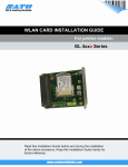
LAN CARD INSTALLATION GUIDE
For printer models:
GL 4xxe Series
1
General
1.1 Important information
Read this Installation Guide before and during the installation
This quick guide provides important information on how to setup your
of the above accessory.
Keep this Installation Guide handy for
new SATO product.
future reference.
LAN Card Installation Guide
Be sure to read this quick guide thoroughly before using this printer. It
is an integral part of the product and should be kept in the immediate
vicinity of the device and available to the operating staff.
1.2 Limitation of liability
All information in this manual have been compiled under due
consideration of federal standards and regulations.
The manufacturer will not be held liable for damage resulting from:
z Disregarding these instructions
z Unintended use of the printer
z Unauthorized technical modifications
z Use of unapproved spare parts
z Use of unapproved consumables
FCC WARNING
Changes or modifications not expressly approved by the party responsible for
compliance could void the user’s authority to operate the equipment.
NOTICE
This equipment has been tested and found to comply with the limits for
a Class B digital device, pursuant to part 15 of the FCC Rules. These
limits are designed to provide reasonable protection against harmful
interference in a residential installation.
This equipment generates, uses and can radiate radio frequency energy
and, if not installed and used in accordance with the instructions, may
cause harmful interference to radio communications. However, there is
no guarantee that interference will not occur in a particular installation.
2
LAN Card Installation Guide
1.3 Explanation of symbols
This instruction manual uses various warning icons to help you
understand the safe operation of your printer. Explanations of the
icons are below.
WARNING!
Indicates neglectful or erroneous use may cause
irreparable damage to the product, serious injury to
the operator, or worse.
CAUTION!
Indicates a specific point where caution should be
used. The graphic within the triangle will indicate the
specific issue, i.e.; the sign on the left indicates a
caution for potential electrical shock.
CAUTION!
Indicates a potentially hazardous situation which,
if not avoided, may result in damage to your
product or host equipment.
NOTE!
Emphasizes useful tips or recommendations for
efficient and smooth operation of your printer.
3
LAN Card Installation Guide
1.4
Contact and Document Information
SATO GROUP OF COMPANIES
.
International Headquarters
Americas
SATO INTERNATIONAL PTE. LTD
438A Alexandra Road #05-01/04,
Alexandra Technopark, Singapore 119967
Phone: 65-6271-2122 Fax : 65-6271-2151
Email: [email protected]
SATO INTERNATIONAL AMERICA, INC.
(Regional HQ)
10350 Nations Ford Road Suite A,
Charlotte, NC 28273
Phone: 1-704-644-1650 Fax: 1-704-644-1662
Email: [email protected]
Americas
SATO AMERICA, INC.
10350 Nations Ford Road Suite A,
Charlotte, NC 28273
Phone: 1-704-644-1650 Fax: 1-704-644-1662
Email: [email protected]
SATO LABELING SOLUTIONS AMERICA, INC.
1140 Windham Parkway, Romeoville, Illinois 60446
Phone: 630-771-4200 Fax : 630-771-4210
Email: [email protected]
Horticultural Division
930 Jimmy Ann Drive
Daytona Beach, FL 32117
Phone: 1-386-274-5566 Fax: 1-386-274-5599
Europe
SATO INTERNATIONAL EUROPE N.V.
(Regional HQ)
Leuvensesteenweg 369, 1932 Sint-Stevens-Woluwe, Brussels, Belgium
Phone: 32(0)-2-788-80-00 Fax: 32(0)-2-788-80-80
Email: [email protected]
SATO UK LTD
Valley Road, Harwich, Essex England Co12 4RR,
United Kingdom
Phone: 44-1255-240000 Fax : 44-1255-240111
Email : [email protected]
SATO LABELLING SOLUTIONS EUROPE GmbH
Ersheimer Straße 71,
69434 Hirschhorn, Germany
Phone: 49-6272-9201-324 Fax: 49-6272-9201-399
SATO POLSKA SP Z O.O.
Ul. Wroclawska 123, 55-015 Radwanice
K/Wroclawia, Poland
Phone: 48-71-381-03-60 Fax: 48-71-381-03-68
Email: [email protected]
SATO FRANCE SAS
Parc D'Activities - Rue Jacques Messager - 59175 Templemars, France
Phone: 33-3-20-62-96-40 Fax: 33-3-20-62-96-55
SATO IBERIA S.A.
Dels Corrals Nous, 35-39, Pol. Can Roqueta,
08202 - Sabadell, Barcelona, Spain
Phone: 34-93-492-5750 Fax : 34-93-786-3451
Asia Pacific & Oceania
SATO INTERNATIONAL ASIA PACIFIC PTE. LTD.
(Regional HQ)
438A Alexandra Road #05-01/04,
Alexandra Technopark, Singapore 119967
Phone : 65-6271-5300 Fax : 65-6273-6011
Email: [email protected]
SATO AUTO-ID MALAYSIA SDN. BHD.
No.25, Jalan Pemberita U1/49, Temasya
Industrial Park
Section U1, 40150 Shah Alam,
Selangor Darul Ehsan, Malaysia
Phone: 60-3-7620-8901 Fax: 60-3-5569-4977
Email: [email protected]
SATO ASIA PACIFIC PTE. LTD.
438A Alexandra Road #05-01/04, Alexandra Technopark, Singapore 119967
Phone: 65-6271-5300 Fax: 65-6273-6011
Email: [email protected]
SATO AUTO-ID (THAILAND) CO., LTD.
292/1 Moo 1 Theparak Road, Tumbol Theparak,
Amphur Muang, Samutprakarn 10270
Phone: 662-736-4460 Fax: 662-736-4461
SATO SHANGHAI CO., LTD.
307 Haining Road, ACE Bldg, 10th Floor,
Hongkou Area,
Shanghai, China 200080
Phone: (86) 021- 63068899 Fax: (86) 021- 63091318
SATO AUSTRALIA PTY LTD.
1/1 Nursery Avenue, Clayton Business Park (1508 Centre Road) Clayton
VIC 3168, Melbourne, Australia
Phone: 61-3-8814-5330 Fax: 61-3-8814-5335
SATO NEW ZEALAND LTD
30 Apollo Drive, Mairangi Bay
PO Box 305-031, North Shore, Auckland, New Zealand
Phone: 64-9-477-2222 Fax: 64-9-477-2228
For a full list of all SATO offices,
refer to www.satoworldwide.com
Extensive contact information of worldwide SATO operations can be found on the Internet at
www.satoworldwide.com
Version: SI-GL4xxe-01rA-05-06-07-NICIG © Copyright 1994 – 2007
All rights reserved. No part of this document may be reproduced or issued to third parties in any form
whatsoever without the express permission of SATO. The materials in this document are provided for
general information and are subject to change without notice. SATO assumes no responsibilities for any
errors that may appear.
4
LAN Card Installation Guide
GL4exe LAN Card Installation
Before installing the LAN card, make sure the printer is OFF and disconnected from
the power supply.
1. Use a Phillips head screwdriver to remove the two screws that secure the
Cover Plate to the LAN Card slot. Set the plate and screws aside.
2. Make sure you have discharged any static electricity (by touching a
grounded component on the printer) and plug the LAN card into the slot so
that it snaps into place. Hold the LAN card by the mounting plate only.
3. Secure the LAN card with the two screws removed in Step 1.
4. Connect the printer to the AC outlet and to the host computer with the
relevant cables and turn the printer ON.
5. Refer to the Operator’s Manual for the procedure to configure the LAN
settings. A summary of this procedure is reproduced on the following page,
but the Operator’s Manual contains further details in the section on
Interfaces Mode (See page 4-52 and subsequent pages).
Figure 1. Removing the interface cover plate and installing the LAN interface card
5
LAN Card Installation Guide
LAN CONFIGURATION FOR ETHERNET CONNECTION
Once the LAN card is installed, you can access the Ethernet settings in the GL’s
Interfaces Mode menu. An overview of the LAN options is listed below, followed
by explanations of relevant LCD menu options in the following pages.
POWER
ONLINE
PARL / SBPL
LINE
INTERFACES
INTERFACES
Host Interface*
Host Interface*
Host Interface
Host Interface
Auto Switching*
Ethernet*
OFFLINE
INTERFACES
ETHERNET PORT
ENTER
ETHERNET PORT
INTERFACES
Timeout
Timeout
10 sec*
Interface
Mode
ENTER
Switch Out On
Data Timeout*
INTERFACES
Ignore CR/LF
Item No. Check
BCC Check
History Buffer
Comm. Protocol
Host Interface
ETHERNET PORT
ETHERNET ADDRESS
ETHERNET SETTING
Parallel Port
USB Port
Serial Port
Printer Mgt
Screens
only display if
Admin User is
enabled within
the Advanced
Mode
INTERFACES
ETHERNET SETTING
ETHERNET SETTING
ETHERNET ADDRESS
IP Address
Subnet Mask
Gateway Address
MAC Address
DHCP
Ignore CR/LF
ENTER
NetBIOS Protocol
NetBIOS Protocol
Enable*
ASCII Data Port
IP Address
1024*
XXX.XXX.XXX.XXX
Ignore CR/LF
No*
Keep Alive Timer
Subnet Mask
3 minutes*
XXX.XXX.XXX.XXX
Item No. Check
Disable*
Ethernet Speed
Gateway Address
Auto Select*
XXX.XXX.XXX.XXX
BCC Check
Disable*
Job Control
MAC Address
Standard*
XXX.XXX.XXX.XXX
History Buffer
Temporary*
Offline Process
DHCP
Disable*
Disable*
Comm. Protocol
Status 5*
Host Interface
Auto Switching*
Figure 2. Overview of the Interfaces Mode menu for LAN configuration
6
LAN Card Installation Guide
The following tables explain the relevant options available via the LCD screen in Interfaces Mode.
Menu screen
What the options mean
Is the menu selection screen for the Host Interface option of the INTERFACES mode.
INTERFACES
Host Interface*
There are only two options relative to the serial interface, ignore all others.
Host Interface
Auto Switching*
• Auto Switching - the printer automatically switches to the relative interface type and moves
into the applicable menus.
• Ethernet - factory default. Allows the operator to select the interface and the relative menus
will follow.
Is the menu selection screen for the Ethernet Port option of the INTERFACES mode.
INTERFACES
ETHERNET PORT
Is a menu subset of the Ethernet Port option. Will move into the Timeout menu.
ETHERNET PORT
Timeout
Timeout
10 sec*
This is the value used by the printer to time out from the current port and check the other selected
Port Types for data print. When the printer has not received data from the host after a certain
period of time, it must timeout in order to service other ports.
The factory default of 10 seconds with an allowable range of 1 to 60 seconds.
Determines when other ports are active and able to communicate with the printer when the
Ethernet interface is not in use.
Switch Out On
Data Timeout*
• Data Timeout - factory default. The other ports (Parallel, Serial, USB) are able to send data
to the printer when the timeout setting has been reached. This setting is adjustable via the
display menu item Timeout.
• Session Close - the other ports (Parallel, Serial, USB) are able to send data to the printer
when the port has been closed. Example: If a RAW port of 9100 is open, the printer will not
accept data from another interface until that port is closed by the host.
Is the menu selection screen for the Ethernet Setting option of the INTERFACES mode.
INTERFACES
ETHERNET SETTING
Is a transitional screen that allows entry into the Net BIOS Protocol menu.
ETHERNET SETTING
NetBIOS Protocol
Allows determination of if the NIC will recognize the NetBIOS protocol.
NetBIOS Protocol
• Enable - factory default. Will recognize.
Enable*
• Disable - will not recognize.
This options allows for the port number to be set for ASCII print jobs. The data port number must
match the host computer setting.
ASCII Data Port
1024*
The allowable range is 0 to 65535, and the factory default is 9100.
7
LAN Card Installation Guide
Menu screen
Keep Alive Timer
3 minutes*
What the options mean
Determines the amount of time that the tcp connection will remain connected after the print job
has terminated.
The allowable range is 2 to 10 minutes, and the factory default is 3 minutes.
This menu appears only if a 10/100Base-t Network Interface Card (NIC) is installed. There are
five different speed modes to allow compatibility with different systmes and networks.
Ethernet Speed
Auto Select*
• Auto Select - factory default. Tells the 10/100Base-T NIC to perform an automatic detection
scheme and configure itself to be one of the other allowable options.
• 10 Half Duplex - communicates at 10 megabytes per second using half duplex.
• 10 Full Duplex - communicates at 10 megabytes per second using full duplex.
• 100 Half Duplex - communicates at 100 megabytes per second using half duplex.
• 100 Full Duplex - communicates at 100 megabytes per second using full duplex. Determines
how the printer and/or NIC card respond when a job has been completed. The definition of
a complete job is also determined by this setting.
Job Control
Standard*
• Standard - factory default. The NIC card responds to the host that the job is complete when
the entire print job has been accepted by the printer.
• Enhanced - the NIC card responds to the host that the job is complete when the entire job
has not only been accepted by the printer, but also completely printed.
• Off - without synchronization between the NIC and the printer. The NIC card is simply a
pass-trough and the printer tells the host when the job is complete.
Determines whether the printer processes incoming data when it is in an offline state.
Offline Process
Disable*
ETHERNET ADDRESS
• Disable - factory default. The printer does not process data while offline.
• Enable - continues to process (but not print) the current network/parallel job while the printer
is offline until in a buffer-near-full state.
Is the menu selection screen for the Ethernet Address option of the INTERFACES mode. Its
menu options are explained in the following five menu screen descriptions.
IP Address
Subnet Mask
Gateway Address
MAC Address
DHCP
This menu allows the IP Address to be set for the TCP/IP protocol in four three-digit segments
(SEG1 through SEG4). If the IP Address is assigned by Bootp, ARP, or DHCP it is dynamic and
read only.
IP Address
XXX.XXX.XXX.XXX
The factory defaults for SEG1 through SEG4 are 000, 000, 000, and 000.
Note: When changing the IP Address, the printer resets the Network Interface Card (NIC) when
the printer is placed online. When the printer resets the NIC, the LCD displays DO NOT POWER
OFF. After the NIC has completed initialization, the LCD displays E-NET INIT to signal that the
NIC andd printer are in initialization process. When both the NIC and printer have completed the
initialization, theLCD displays E-NET READY.
Allows the Subnet Mask to be set for the TCP/IP protocol in four three-digit segments (SEG1
through SEG4). If the Subnet Mask is assigned by Bootp, Arp or DHCP, it is dynamic and read
only.
Subnet Mask
XXX.XXX.XXX.XXX
The defaults for the SEG1 through SEG4 are 000, 000, 000, and 000.
Note: When changing the Subnet Mask, the printer resets the NIC when the printer is placed
online. When the printer resets the NIC, the LCD displays DO NOT POWER OFF. After the NIC
has completed its initialization, the LCD displays E-NET INIT to signal that the NIC and printer are
in the initialization process. When both the NIC and printer have completed initilization, the LCD
displays E-NET READY.
8
LAN Card Installation Guide
Menu screen
What the options mean
Allows the Gateway Address to be set for the TCP/IP protocol in four three-digit segments (SEG1
through SEG4). If the Gateway Address is assigned by Bootp, ARP, or DHCP, it is dynamic and
read only.
Gateway Address
XXX.XXX.XXX.XXX
MAC Address
The defaults for the SEG1 through SEG4 are 000, 000, 000, and 000.
Note: When changing the Gateway Address, the printer resets the NIC when the printer is place
online. When the printer resets the NIC, the LCD displays DO NOT POWER OFF. After the NIC
has completed its initialization, the LCD displays E-NET INIT to signal that the NIC and printer are
in the initialization process. When both the NIC and printer have completed initialization, the LCD
displays E-NET READY.
This is an informational screen that displays the manufacturer’s assigned number. This number is
unique for each NIC.
XXX.XXX.XXX.XXX
DHCP
Disable*
Allows the DHCP protocol to be enabled or disabled through this menu.
The factory default is Disable.
Note: Consult with your systems administrator for the appropriate setting.
Once the LAN settings are correct for your requirements, the installation of the LAN interface can be
considered complete.
9
LAN Card Installation Guide
10