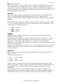
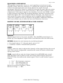
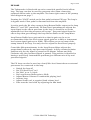
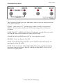
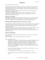
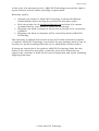
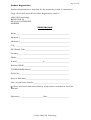
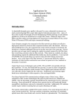
1
page 1 of 22
WELCOME to TUBEWONDER!
Now, what does one write as an introduction to a User Manual?
The usual blah-bragging-blah stuff?
Well, TUBEWONDER is an unusual amplifier.
Period.
All I’d like to say is:
I wish you a lot of fun with your new TUBEWONDER amplifier.
It’s simply a great amp. I know. I had a lot of fun building it.
About this Manual. Please read it.
There’s some useful info that might come handy.
In short, set all knobs at 12 o’clock; try different footswitch combinations.
Twiddle the knobs to FREE YOUR TONE.
Forget the amp and just make music!
Most important: have fun!
Give me a call - I’d like to hear you smile.
Aleksander Niemand – Amp Creator Extraordinaire
© 2006, 2007 ANACON Technology
page 2 of 22
IMPORTANT SAFETY INSTRUCTIONS
BEFORE CONNECTING AND OPERATING THE APPARATUS READ ALL OF THESE INSTRUCTIONS!
•
•
•
•
•
•
•
•
•
•
•
•
•
•
•
•
•
•
•
•
•
•
•
•
•
Save these instructions for later use.
Follow all warnings and instructions marked on the apparatus.
Keep this apparatus inaccessible to children and animals
Do not use this apparatus in tropical climate
Do not use this apparatus near water, i.e. bathtub, sink, swimming pool, humid
basement, etc.
The apparatus must be used in horizontal position only.
Do not place this apparatus on an unstable cart, stand or table. A falling apparatus
may suffer damage or inflict serious harm to persons!
Slots and openings in the cabinet front, back and top/bottom are provided for
ventilation and heat dissipation to ensure reliable operation of the apparatus and to
protect it from overheating. These openings must never be blocked or covered.
This apparatus should not be placed in a built-in installation unless proper
ventilation is provided.
This apparatus should not be placed near a source of heat such as a stove, radiator,
or another heat producing apparatus.
Use only the supplied power cord.
Consult your dealer or local power company if you are unsure of the type of power
available.
Do not allow anything to rest on the power cord. Do not place this apparatus where
persons will walk on the cord.
Never break off the ground pin on the power supply cord.
Power supply cords should always be handled carefully. Periodically check cords for
cuts or sign of stress, especially at the plugs or the point where the cord exits the
unit.
The power supply cord should be unplugged when the apparatus is to be left
unattended or unused for long periods of time.
Should this apparatus be mounted in an equipment rack, rear support should be
provided.
This apparatus should be used only with a cart or stand that is recommended by
ANACON Technology.
Never insert objects of any kind into this apparatus through cabinet slots as it may
cause damage to sensitive parts and touch dangerous voltage points or short out
parts that could result in risk of fire or electric shock.
Never spill liquid of any kind on or into the apparatus.
Do not place liquid containers of any kind on the apparatus.
Do not place any naked flame sources such as candles and the like on or near the
apparatus
Do not attempt to service this apparatus yourself as opening or removing covers may
expose you to dangerous voltage points and dangerously hot parts or other risks.
Refer all servicing to qualified service personnel.
Unplug this apparatus from the wall outlet and refer servicing to qualified service
personnel should any of the following occur:
o Power cord or plug is damaged or frayed.
o Liquid has been spilled into the apparatus.
o The apparatus has been exposed to rain or water.
o The apparatus does not operate normally when the operating instructions are
followed.
o The apparatus has been dropped or the cabinet has been damaged.
o The apparatus exhibits a distinct change in performance indicating a need of
service!
Adjust only these controls that are covered by the operating instructions. Improper
adjustment of any other controls may result in damage and will often require
extensive work by a qualified technician to restore the apparatus to normal
operating condition.
Fuses: Replace ONLY with IEC127 (5 x 20 mm) type and rated fuse for best and safe
operation!
© 2006, 2007 ANACON Technology
Page 3 of 22
TO PREVENT RISK OF FIRE AND ELECTRIC SHOCK DO NOT EXPOSE THIS
APPARATUS TO MOISTURE OR RAIN. DO NOT OPEN. NO USER SERVICEABLE PARTS
INSIDE. REFER SERVICING TO QUALIFIED SERVICE PERSONNEL.
IMPORTANT ADVICE ON SAFETY!
READ BEFORE USE AND SAVE FOR LATER USE!
This apparatus has been built by ANACON Technology in conformance with IEC/EN
60065 and left the factory in safe working condition. To maintain this condition and
ensure safe operation, the user must follow advice and warning comments found in the
operating instructions.
THIS APPARATUS CONFORMS TO PROTECTION CLASS 1 (protectively earthed) AND
MUST BE CONNECTED TO AN EARTHED MAINS POWER OUTLET TO MAINTAIN
PROPER PROTECTION AGAINST ELECTRICAL HAZARDS.
ANACON TECHNOLOGY ONLY GUARANTEES THE SAFETY, RELIABILITY AND
CORRECT FUNCTION OF THE APPARATUS IF AND ONLY IF:
•
•
•
•
Assembly, extension, re-adjustment, modifications or repairs are carried out by
ANACON Technology or by persons authorized by ANACON Technology to do so.
The electrical installation of the relevant area of use complies with the requirements
of IEC (ANSI) specifications.
The apparatus is used and operated in accordance with the operating instructions.
The unit is regularly checked and tested for electrical safety by a competent
technician.
WARNING:
• If covers are opened or sections of casing are removed, except where this can be
done manually without using any tools, electrically live parts can become exposed.
• If it is necessary to open the apparatus it must be isolated from all power sources.
Please take this into account before carrying out adjustments, maintenance, and
repairs and before replacing parts.
• Adjustments, maintenance and repairs inside the apparatus may only be performed
by technicians trained and authorized by the manufacturer and who are aware of
associated hazards.
• Loudspeaker outputs marked with the lightning symbol can carry hazardous
voltages. Before switching the apparatus on, the loudspeaker must be connected
using cable recommended or supplied by the manufacturer.
• Where possible, all plugs on connection cables must be screwed or locked onto the
casing.
• Replace fuses only with IEC127 (5x 20 mm) type and correct rating!
• It is absolutely forbidden to use repaired fuses or to short-circuit the fuse holder.
• Never interrupt the protective earth conductor connection.
• Surfaces which are equipped with the „HOT“ mark, rear panels or covers with
cooling slits, cooling bodies and their covers, as well as tubes and their covers are
purposely designed to dissipate high temperatures and should not be touched.
• High sound levels can cause permanent hearing damage. You should therefore avoid
the direct vicinity of loudspeakers operating at high levels. Wear hearing protection if
continuously exposed to high sound levels.
MAINS CONNECTION:
•
•
•
•
•
The apparatus is designed for continuous operation.
The set operating voltage must match the local mains supply voltage.
The mains switch on the apparatus must be in OFF position before the mains cable
is connected.
Use only the supplied mains power cable.
Never use any damaged connection cable. A damaged cable must be replaced by a
new undamaged one or repaired by a competent technician.
© 2006 ANACON Technology
Page 4 of 22
•
Avoid connection to the mains supply in distributor boxes together with several
other power consumers.
INSTALLATION SITE:
•
•
•
•
•
•
•
•
•
•
•
•
•
•
•
•
•
The apparatus should be placed only on a clean, horizontal working surface.
The apparatus must not be exposed to subsonic vibrations during operation.
Keep away from moisture and dust.
Do not place the apparatus near water, baths, washing basins, kitchen sinks, wet
areas, swimming pools or damp rooms.
Do not place liquid containers on the apparatus - vases, glasses, bottles etc.
Ensure that the apparatus is well ventilated.
Any ventilation openings must never be blocked or covered.
The apparatus must be positioned at least 20 cm away from walls.
The apparatus may only be mounted in a rack if adequate ventilation is ensured and
if the manufacturer’s installation instructions are followed.
Keep away from direct sunlight and the immediate vicinity of heating elements or
similar devices.
Keep away from children and animals.
Condensation can form inside the apparatus when it is moved from a cold to a warm
location. This must be taken into account particularly in the case of vacuum
(electron) tube units. Wait until the unit has reached room temperature before
connecting to the mains power and switching on.
Accessories: Do not place the unit on an unsteady trolley, stand, tripod, base or
table.
If the unit falls down it can cause personal injury and itself become damaged. Use
therefore the apparatus only with the loudspeaker cabinet, trolley, rack stand,
tripod or base recommended by the manufacturer or purchased together with the
apparatus.
Manufacturer’s instructions must be followed and recommended setup accessories
must be used when installing the apparatus. Any combination of apparatus and
stand, including but not limited to, loudspeaker cabinet must be moved carefully. A
sudden stop, excessive use of force and uneven floors can cause the combination of
apparatus and stand to tip over.
Additional equipment: Never use additional equipment that has not been
recommended and approved by the manufacturer as this can cause malfunction or
accidents.
To protect the apparatus during bad weather or when left unattended for prolonged
periods, the mains plug must be disconnected. This prevents the unit being
damaged by lightning and power surges in the AC mains supply.
© 2006 ANACON Technology
Page 5 of 22
IMPORTANT NOTE ON LOUDSPEAKER CABINET:
IF YOUR SPEAKER CAB IS EQUIPPED WITH CASTERS:
Make sure the casters are SECURED as in photo below on the right TO
PREVENT ACCIDENTAL TOPPLING:
!WRONG!
CORRECT
BRAKES ENGAGED
DO NOT ROLL THE CAB ACROSS FLOORS ETC WITH AMP HEAD ON TOP.
CARRY THE AMP SEPARATELY.
© 2006 ANACON Technology
Page 6 of 22
© 2006 ANACON Technology
Page 7 of 22
DESCRIPTION OF CONTROLS
All controls will be described in sequential order following the preamplifier
block diagram:
© 2006 ANACON Technology
Page 8 of 22
INPUT SENSITIVITY SWITCH
Sensitivity Switch is placed above the Input Jack. This
2-position switch varies the sensitivity and impedance of
the amp’s input.
•
•
High: Input impedance 1 MΩ, no signal
attenuation
Low: Input impedance 120kΩ, 6db signal
attenuation
GAIN & HARMONICS CONTROL
This section controls preamplifier’s gain structure
and distortion characteristics.
LEVEL - adjusts preamp output signal level to the
EQUALIZER
Gain – this 3-position switch operates on the 1st gain stage and provides
basic gain settings:
• Bright, left, +4db boost at 4kHz, onset at 400Hz
• Norm, center,
standard setting
• Boost, right, + 4db gain full range boost
An additional gain control is activated by the Footswitch: 2nd preamplifier
stage gain can be boosted by 4db for added crunch on clean sound.
DRIVE - controls overdrive characteristics in the preamplifier’s 3rd gain
stage. Adjusting the gain varies the amount of distortion.
This 3rd gain stages can be bypassed using the footswitch for clean to
crunch sound.
LEVEL control is signalwise placed after the DRIVE control. It has no effect
on the preamp distortion thus allowing the GAIN & DRIVE setting to be very
sensitive to the guitar’s volume control. However, LEVEL setting has
influence on how much, if any, additional distortion will be generated in the
EQUALIZER. This, together with MASTER Volume affects output power amp
distortion.
Harmonics switch allows a choice of 2 different distortion characters:
•
•
2/3, mostly even harmonics in the distortion spectrum
3/2, mostly odd harmonics in the distortion spectrum
The difference between these 2 switch positions is most audible when
playing with moderate DRIVE and GAIN levels in the range of clean/dirty to
© 2006 ANACON Technology
Page 9 of 22
crunch sounds, at maximum distortion the difference will be less noticeable.
The sound in the 3/2 position will be a little brighter and edgier than in the
2/3 position.
SEMI-PARAMETRIC ACTIVE EQUALIZER
This is the main TONE
CONTROL section of the
TUBEWONDER amplifier.
Although it may appear
complicated at first it is
very easy to use once you
become familiar with the
function of each control.
The Equalizer has 4 rotary controls:
BASS, MIDDLE, TREBLE and HIGHCUT
Additionally, 4 toggle switches located below the potentiometer knobs
provide extended control of the amplifier’s tonal characteristics.
To familiarize yourself with the EQUALIZER begin by setting the 4 switches
in following positions:
•
•
•
•
BASS “HP” switch:
MIDDLE switch:
TREBLE switch:
HIGHCUT switch:
Left (filter OFF)
Center (High)
right (shelving)
Center (Off)
Setting the BASS, MIDDLE & TREBLE potentiometers to “-0+” results in
flat frequency response and NO SIGNAL LEVEL LOSS, as is the case with all
passive tone controls.
When you turn BASS & TREBLE controls with the MIDDLE at the center “0+” position the equalizer will behave like a standard active Baxandall-type
tone control. You will notice that the boost/cut effect is strongest at the
lowest and highest frequencies, respectively.
The type of chosen boost or cut characteristic is indicated by the graphic
symbols at the respective switch:
Left off BASS switch and right off TREBLE switch is the symbol for
“shelving” boost/cut.
The symbol right off TREBLE switch indicates “peaking” or “bell” shaped
frequency response.
Toggle switch below BASS control: see HP filter section further down.
BASS
BASS control acts on a frequency band centered on 150Hz and leaves the
lowest frequencies below about 70Hz unaffected. This allows emphasizing
the bass range without boosting the lowest rumble.
© 2006 ANACON Technology
Page 10 of 22
HP (High Pass) filter
This is an active 2nd order (12db/octave) 125Hz high-pass filter that can be
switched in before the equalizer section. HP filter can efficiently remove
boominess from some loudspeaker cabs and is very efficient in tightening up
the bass response. Turn the filter on and boost bass at the same time for
strong tight bottom rich tone.
MIDDLE
Most of the tone character and color is determined by the midrange and
treble. TUBEWONDER’s MIDDLE EQ-section has 3 switched mid
frequencies and a dual function HIGH-CUT filter in addition to the TREBLE
control.
The MIDDLE potentiometer together with its center frequency switch “Freq”
is a very versatile tool that gives a very wide range of tone adjustment. The
standard center frequencies are:
•
•
•
Low: 375Hz
Mid: 750Hz
High: 1300Hz
TREBLE
TREBLE switch changes the boost/cut characteristic from shelving to
peaking around 3.2kHz.
Set the switch to “peak/dip” position and turn the pot to about +3 … then
flip the switch to shelving position: now the extreme treble range is also
enhanced – that’s where the shimmer is. It may be too much with a
Telecaster or a Stratocaster’s bridge or mid pick-up so you may want to back
off on the control a bit.
Now turn the treble pot to about –4 or so …then flip the switch to peak/dip
position: this will give you a darker tone but with the edge of pick attack
cutting through.
HIGH-CUT
This is an active low-pass filter with 2 switched cut-off frequencies and
variable slope.
The switch positions are:
1. Left:
Soft 900Hz
2. Center. Off
3. Right:
Hard 400Hz
“Soft” position is mainly aimed at fine-tuning the shimmering end of the
treble range while “Hard” setting is useful for achieving very dark tones and
taming high order harmonics that may arise when playing with heavy
distortion.
All controls provide ca +12/-12db of boost/cut at center frequencies in
peaking position as standard. Bass & Treble in shelving position provide +/15db control range at the extremes of their respective frequency ranges.
© 2006 ANACON Technology
Page 11 of 22
EQUALIZER & DISTORTION
The equalizer is an active circuit i.e. each equalizer section has its own
amplifier triode. With any control in +0- position the respective equalizer
section has 0db signal gain and simply passes the signal through
unchanged. When the control is turned to boost this section’s gain increases
and has it’s maximum at the center frequency. What does it mean in terms
of distortion? If the input signal to the equalizer as set by the LEVEL control
is high enough it will cause the boosting equalizer section to overdrive and
distort the signal. BUT: not all signals will be distorted, only frequencies at
and around the boost center frequency will be amplified and eventually
cause that equalizer section to overdrive and produce additional distortion.
This is yet another way to tailor the tone and distortion character.
MASTER VOLUME, REVERB MIXER & TONE CONTROL
MASTER
Adjusts signal level to the power amplifier. The MASTER potentiometer is
driven by a low impedance signal source and therefore does not affect tone.
REVERB adjusts the mix between dry and delayed signal
• Dry signal only at “0”, delayed signal only at “10”
• A mixture of both at intermediate positions
DWELL
DWELL control is used to adjust the intensity of the signal driving the reverb
tank. This reverb configuration resembles the sound of classic stand-alone
spring reverb units.
TONE control affects only the delayed signal fed to REVERB mix control.
Main Equalizer has no effect on the tone of the delayed signal except for
HIGHCUT filter that affects the mixed signal. This is a tone balance type of
control:
• “-0+” - flat frequency response
• “-5” - low-boost/high-cut
• “+5” - low-cut/high-boost
Boost/cut turnover frequency 700Hz
Boost/cut range: +/- 8db
© 2006 ANACON Technology
Page 12 of 22
FX LOOP
The Tubewonder is fitted with an active cross fade parallel/serial effects
loop. The loop can also be used for purposes other than connecting
outboard effects units to the amplifier. See lower right corner of the preamp
block diagram on page 7.
Pressing the “LOOP” switch on the foot pedal activates FX loop. The loop is
in bypass mode if foot pedal is disconnected from the amplifier.
In active mode the K4 relay connects Loop Return Buffer output to the Loop
Mixer (“C” and “NO” connected). FX Send Level potentiometer adjusts the
input signal to the effects processor in the loop. It should be set to the
maximum level that the processor will accept. Processed signal from the
effects loop then goes through the Loop Return Buffer to the Loop Mixer.
Loop Return Buffer has a gain switch so that its gain can be set to
accommodate either line level return signal (gain set to 0db) or instrument
level return signal (gain set to 20db). This allows you to use most of the
stomp boxes in the loop. You only need to adjust the Send Level properly.
Cross fade (Mix potentiometer in the Loop Return Mixer adjusts the
proportions between dry and processed signals. In fully counterclockwise
position only the dry signal is passed to the Master Volume and fully
clockwise only the processed signal is passed. This position is identical to
having a serial loop. Intermediate positions give different mix of dry and
processed signals.
The FX Loop can also be used as a Lead/Solo Level boost when no external
processors are connected to the loop:
• Switch the loop off
• Set “FX Send Level” to 0
• Set “Mix” to ca 3 o’clock
• Set Loop Return Buffer gain to 20db
• Adjust Master Volume to comfortable playing level.
• Activate loop
• Adjust Send Level to required Lead volume level.
• Fine-tune the level shift by adjusting the Mix knob.
© 2006 ANACON Technology
Page 13 of 22
FOOTSWITCH PEDAL
The Footswitch Pedal gives you additional control over the amp beyond the
front panel controls.
BOOST – gain boost in 2nd preamp stage, adds crunch to clean sound
DRIVE – activates/deactivates the 3rd preamp stage with its Harmonic
Overdrive
BURN: BOOST + DRIVE both ON give a high gain preamp, fine tune with
the DRIVE control and Harmonics switch on the amp.
CLEAN: BOOST & DRIVE both OFF for clean dynamic sound
REVERB: Turns the Reverb On/OFF.
LOOP: Turns the FX loop ON/OFF; can be used as Lead/Solo boost, see
description of the FX LOOP.
NOTE: With Footswitch Pedal UNPLUGGED from the amplifier following
functions remain activated: BOOST, DRIVE and REVERB. LOOP will be
inactive in bypass mode.
© 2006 ANACON Technology
Page 14 of 22
POWER & STAND-BY Switches
THIS APPARATUS CONFORMS TO PROTECTION CLASS 1 (protectively
earthed) AND MUST BE CONNECTED TO AN EARTHED MAINS POWER
OUTLET TO MAINTAIN PROPER PROTECTION AGAINST ELECTRICAL
HAZARDS.
Before turning the POWER on:
•
Check that the available mains power matches
marking on the label below amplifier’s power
socket.
Make sure that POWER and STDBY switches are
in the OFF position
Turn MASTER volume control to 0
•
•
•
•
•
•
•
•
•
Connect the loudspeaker to the amplifier
Adjust the OUTPUT IMPEDANCE switch to match the loudspeaker
Connect power cord to amplifier’s mains socket
Plug the other end of power cord to an earthed wall mains socket
Turn POWER on, check that RED pilot light comes on, wait about 5
minutes before flipping the STDBY switch to PLAY position.
Flip the STDBY switch to PLAY; check that GREEN pilot light comes
on.
NOTE: Immediately after flipping the STDBY to PLAY there will be a 12 sec short humming sound coming from the loudspeaker. This is
normal due to initial charging of filter capacitors in the amplifier’s
high voltage supply.
It usually takes up to 10 minutes for all the tubes to reach their
optimal stable working conditions.
Switching the amplifier off:
•
•
•
•
Turn the MASTER volume control to 0
Flip the STDB/PLAY to STDB position. This will allow all capacitors,
especially those in the high voltage power supply to discharge
properly.
Flip the POWER switch to OFF position
Remember to check loudspeaker connection before turning the power
back on.
It is advisable to put the amplifier in STANDBY mode during intermissions,
food breaks etc.
© 2006 ANACON Technology
Page 15 of 22
Mains Voltage
IMPORTANT NOTE: Your Tube wonder amplifier is factory wired for
operation with mains voltage in your country i.e. 100, 120, 230 or 240Vac.
The pre-wired mains voltage is indicated on the plate located below mains
inlet socket on amplifier’s rear panel.
Rewiring to different mains voltage must be performed only by a qualified
technician according to factory instructions.
TUBE PLACEMENT
The Tubewonder is shipped from factory with tubes removed and packed in
a separate box. Your dealer will have installed the tubes and checked the
amp prior to delivering the amplifier to you.
Note: There can be different power tubes supplied with your particular
amplifier depending on model ordered.
Tube type 7591 must not be replaced with any other type under any
conditions.
TUBE OR SILICON RECTIFIER
The TUBEWONDER has a built-in silicon rectifier. It is activated by
replacing rectifier tube with the supplied jumper plug. Power tube bias is
factory adjusted for correct operation with the silicon rectifier.
CHANGING TO/FROM TUBE/SILICON RECTIFIER MUST BE DONE WITH
THE AMPLIFIER POWERED OFF AND DISCONNECTED FROM THE MAINS
POWER.
ALLOW 15-20 MINUTES FOR THE AMPLIFIER TO COOL BEFORE
ATTEMPTING THIS OPERATION.
BIASING PROCEDURE
THE BIAS VALUES SHOWN IN THIS PROCEDURE ARE FOR
ILLUSTRATION ONLY.
© 2006 ANACON Technology
Page 16 of 22
RECOMMENDED BIAS RANGE IS 25-35 FOR EL34, 6L6 & 7591A
POWER TUBES.
When do you need to check/adjust bias?
Your Tubewonder was properly adjusted at time of final test with nominal
mains voltage and should not need any adjustments. It has also been
checked by your dealer who installed the tubes upon delivery. The amp was
delivered with the tubes that were used during final test and burn-in.
We recommend checking/adjusting bias after ca 200hrs of use or when
replacing the power tubes.
You will need to readjust the bias when changing to/from Tube Rectifier
from/to Silicon (using supplied jumper plug) It is recommended to set bias
in the lower range when using Silicon Rectifier.
Connect the loudspeaker
to the amp. Turn Level &
Master to 0. Make sure
POWER & STDBY
switches are in OFF
position. Connect mains
power cord to the amp
and mains outlet.
Connect a DMM set to DC
Volts range 100 or 200mV
to the test points as
shown above: (-) lead to
the white GND socket, (+)
lead to red Vta socket.
Turn the mains power ON
Wait ca 5 minutes, DMM
should read 000
Insert a screwdriver with
a ca 3mm wide chisel into
the “Level” trim pot,
check that the chisel has
engaged with trimpot
adjustment screw by
giving it a half turn in
either direction. Note that
both Level & Balance trim
pots are 15 turn devices.
Turn the STDBY switch to
PLAY
Observe the DMM, if the
reading is higher than
35mV adjust it down by
turning the screwdriver
counterclockwise.
© 2006 ANACON Technology
Page 17 of 22
Remove the DMM (-) lead
from the GND test socket
and insert it into the
other red test socket Vtb.
Observe the DMM
reading, if it is higher
than 2mV you need to
adjust the Bias Balance.
Insert the screwdriver
into the Balance trimpot
and adjust for 00 reading
on the DMM.
Let the amp warm up
properly for about 15-20
minutes.
Take a new bias level
reading every few minutes
and at the end of
warming up period make
final fine adjustments of
both Bias Level and
Balance.
BIAS VALUE RANGE FOR 7591A TUBES:
SILICON RECTIFIER
TUBE (GZ34)
25-30
30-35
© 2006 ANACON Technology
Page 18 of 22
DELIVERY CHECK
Detailed test/measurements report is archived at ANACON Technology
HQ.
Model
Manufacture date
Serial No
Power Transformer
Rectifier
Output Transformer
Power Tubes
Phase Inverter
Preamp
Reverb Driver
Reverb Tank
Pre-wired Mains
Voltage
OUPUT POWER
Tube rectifier
Solid State
rectifier
15 minutes warm-up
time
5% THD (clipping onset)
Full clipping
© 2006 ANACON Technology
Page 19 of 22
SPECIFICATIONS
subject to change without prior
notice. Nothing is so perfect that it
can’t be improved.
Dimensions
Weight
Construction
Covering
CONFIGURATION
Output Power
Power consumption
Tubes
Preamp & EQ
Reverb driver
Reverb return
Phase splitter
Output Power Stage
Rectifier
Gain structure
Reverb tank
Reverb Dwell control
Reverb “Tilt” Tone Balance,
independent of main EQ
Turnover frequency
Active High-Cut filter –3db
frequencies
Active Low-Cut filter
Active Bass EQ: peak-dip
Active Mid EQ: peak-dip
Active Treble EQ: switched peakdip/shelving
FX Loop
Cross fade parallel/serial with
SEND and WET/DRY mix
controls
Low noise FX-return buffer
FX send can be used as LINE
OUT
Active loop return mixer
Loop doubles as SOLO BOOST
when not used for effects
Foot Switch Pedal
Accessories: Padded 3 layer
protective covers
AMPLIFIER HEAD
575x275x250mm (WxHxD)
19 kg
Chassis: 2mm brushed anodised welded
aluminium with pigmented labels.
Cabinet: 15mm birch plywood, front &
rear panels 11mm birch plywood with
mahogany/birch veneer.
Leather touch vinyl, Two-Tone covering
optional
Model 35
Model 50
35W at onset of
50W at onset of
power stage
power stage
clipping - 5%THD
clipping - 5%THD
150VA
100/120/230/240V
50/60Hz
LOUDSPEAKER CABINET
575x670x300mm (WxHxD)
14kg unloaded to 25kg loaded
100W, ¼ open or closed back
15mm birch plywood
19mm MDF baffle
Speakers: Eminence
2 x 12” Private Jack
2 x 12” Cannabis Rex
Or 1 of each placed diagonally
Impedance 4 ohm
Leather look vinyl
Acoustone grill cloth
OPTIONS
4x10” or 1x15”
Celestion, Jensen, Weber, etc speakers
on request.
Optional casters
230VA
100/120/230/240V
50/60Hz
1 x ECC803S, 2xECC83S
1 x ECL82
1 x ECC83S
1 x ECC83S
2x6L6GC or 7591S
2xEL34 or 6550
1 x 5A4R or SS
Solid State
3 gain stages in the preamp
3rd gain stage activated with footswitch
1 stage post EQ
Accutronics medium delay
3 springs, short tank
Adjusts reverb spring saturation level
+-8db
NOS tubes on request
KT66, KT77, KT88,
Gain distribution between stages can
be individually adjusted on request
Full range of Accutronics reverb tanks
Mu-metal shielding optional
Reverb Send switch Pre/Post EQ
750Hz
500 & 900Hz
125Hz 12db/oct
+/-12db 150Hz center frequency
+-12db 350/700/1100Hz
+/-12db 3300Hz center frequency
Other frequencies on request
preserved signal polarity/phase
0/20db gain, 330kOhm input
triode section of ECL82
2nd gain stage boost ON/OFF
3rd gain stage “DRIVE” ON/OFF
Reverb ON/OFF
FX Loop ON/OFF
With 2 side pockets
© 2006 ANACON Technology
No pockets on speaker cabinet cover
Page 20 of 22
WARRANTY
Term of warranty: 24 months
ANACON Technology warrants this product free from defects in material or
workmanship at the time of manufacture. This warranty is valid only in
accordance with our warranty conditions from the date of purchase for the
period indicated above.
In the event that this product requires servicing, contact an authorized
ANACON Technology dealer.
This warranty applies exclusively to the device identified by the serial
number in the “Delivery Check” table in this User Manual and is not
transferable to other products.
Warranty conditions:
This warranty is void without the original sales receipt as proof of purchase.
The terms and performance of warranty in other European and overseas
countries are solely the responsibility of the dealers domiciled there.
Warranty period extension and/or transfer to 2nd owner
This warranty is valid for the first owner only. The warranty can be extended
beyond the 24 months period or transferred to 2nd owner for an additional
12 months period but not exceeding a total of 36 months from date of
original purchase.
To obtain warranty extension and/or transfer to 2nd owner the product must
be inspected and, if needed, serviced by ANACON Technology or its
authorized local dealer for a nominal fee before expiration of the primary 24
months warranty.
Warranty exemptions
Panel mounted and internal fuses, knobs, power cords are not covered by
this warranty
Tubes are limited to 60 days warranty from date purchase
This warranty is void if
•
ANACON Technology or its local dealer/representative determines that
the product has been damaged by improper or faulty handling,
installation, transport, or service, failure to comply with the User
Manual’s operating and safety instructions, application errors,
misuse, accident, neglect, or as the result of a repair or service not
carried out by ANACON Technology or an authorized dealer or as the
result of normal wear.
•
the serial number of the device has been removed, defaced, or in any
other way rendered illegible.
•
non-original parts or tubes have been installed in the device.
•
power soaks, attenuators or similar peripheral devices have been
used.
© 2006 ANACON Technology
Page 21 of 22
In the event of a warranty service, ANACON Technology reserves the right to
repair defective devices before providing a replacement.
Warranty repairs:
•
•
•
•
Consult your dealer or ANACON Technology to obtain RA (Return
Authorization) before sending the product for warranty repair.
Pack the product in its original shipping box and ship it by means
recommended by your dealer or ANACON Technology
Shipping cost from customer to service site or factory to be covered by
customer
Shipping cost back to customer will be covered by dealer/ANACON
Technology
This warranty is limited and is made in lieu of all other warranties express
or implied. ANACON Technology is not liable for any damages and/or loss of
revenues or profits resulting from the use or malfunction of the product.
If during an inspection of the product ANACON Technology finds that the
defect is not covered by warranty or that the term of the warranty has
expired, the customer is liable for all costs of inspection and repair including
shipping both ways.
© 2006 ANACON Technology
Page 22 of 22
Product Registration
Product Registration is required for the warranty period to commence.
Copy, fill in and send this Product Registration card to
ANACON Technology
BANGATAN 56
SE-41464 GOTEBORG
SWEDEN
REGISTRATION
Name___________________________________________________________
Address 1________________________________________________________
Address 2________________________________________________________
City_____________________________________________________________
ZIP/Postal Code_________________________________________________
Country_________________________________________________________
Phone___________________________________________________________
E-mail_____________________________@____________________________
Website WWW._________________________________________________
TUBEWONDER Model __________________________________________
Serial No:_______________________________________________________
Date of Purchase________________________________________________
Place of purchase/Dealer________________________________________
I have read and understood Safety Instructions included in the User
Manual.
Signature__________________________Date_________________________
© 2006 ANACON Technology