1
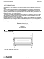
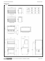
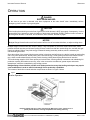
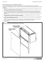
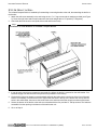
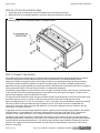
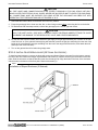
IMPORTANT FOR FUTURE REFERENCE
Please complete this information and retain
this manual for the life of the equipment:
Model #: __________________________
Serial #: __________________________
Date Purchased: ___________________
Installation & Operations Manual
Infrared Compact Broiler
B36-NFR
B48-NFR
WARNING
Improper installation, adjustment, alteration, service, or maintenance can cause property damage, injury, or death.
Read installation, operation, and maintenance instructions thoroughly before installing or servicing this equipment.
1100 Old Honeycutt Road, Fuquay-Varina, NC 27526 USA • www.blodgettrange.com
MANUAL 1186529 REV 2 (02/06)
$30.00
INFRARED SALAMANDER BROILER
MANUAL SECTION SR
SAFETY PRECAUTIONS
INFRARED COMPACT BROILER
SAFETY PRECAUTIONS
Before installing and operating this equipment, be sure everyone involved in its operation is fully trained and aware of
precautions. Accidents and problems can be caused by failure to follow fundamental rules and precautions.
The following symbols, found throughout this manual, alert you to potentially dangerous conditions to the operator,
service personnel, or to the equipment.
DANGER
This symbol warns of immediate hazards that will result in severe injury or death.
WARNING
This symbol refers to a potential hazard or unsafe practice that could result in injury or
death.
CAUTION
This symbol refers to a potential hazard or unsafe practice that could result in injury,
product damage, or property damage.
NOTICE
This symbol refers to information that needs special attention or must be fully understood,
even though not dangerous.
WARNING
FIRE HAZARD
FOR YOUR SAFETY
Do not store or use gasoline or other flammable vapors and liquids in the vicinity of cooking appliances.
Keep area around cooking appliances free and clear of combustibles.
Purchaser of equipment must post in a prominent location detailed instructions to be followed in the event the
operator smells gas. Obtain the instructions from the local gas supplier.
WARNING
BURN HAZARD
Contact with hot surfaces will cause severe burns. Always use caution when operating cooking appliances.
WARNING
EXPLOSION AND ASPHYXIATION HAZARD
In the event a gas odor is detected, shut down equipment at the main gas shutoff valve and immediately call the
emergency phone number of your gas supplier.
Improper ventilation can result in headaches, drowsiness, nausea, and could result in death. Do not obstruct the
flow of combustion and ventilation air to and from cooking appliances.
WARNING
ELECTRIC SHOCK HAZARD
For appliances that use electric power, disconnect the power to the appliance before cleaning. Do not remove
panels that require tools to remove.
NOTICE
Blodgett Range appliances are intended for commercial use only. Not for household use.
Warranty will be void if service work is performed by other than a qualified technician, or if other than genuine
Blodgett Range replacement parts are installed.
Give this Owner’s Manual and important papers to the proper authority to retain for future reference.
Copyright © 2006 by Blodgett Range. All rights reserved. Published in the United States of America.
PAGE 2 OF 24
INSTALLATION & OPERATIONS MANUAL 1186529 REV 2 (02/06)
INFRARED COMPACT BROILER
INTRODUCTION
INTRODUCTION
Congratulations! You have purchased one of the finest pieces of heavy-duty commercial cooking equipment on the
market.
You will find that your new equipment, like all Blodgett Range equipment, has been designed and manufactured to
meet the toughest standards in the industry. Each piece of Blodgett Range equipment is carefully engineered and
designs are verified through laboratory tests and field installations. With proper care and field maintenance, you will
experience years of reliable, trouble-free operation. For best results, read this manual carefully.
RETAIN THIS MANUAL FOR FUTURE REFERENCE.
This manual is for the Blodgett Range Infrared Compact Broiler, which may be mounted over a range or on a wall, or
used as a countertop unit by attaching legs to the base. The serial plate is located under the broiler bottom grease
drawer at the front, toward the left (see Figure 1 below).
Read these instructions carefully before attempting installation. Installation and initial startup should be performed by
a qualified installer. Unless the installation instructions for this product are followed by a qualified service technician (a
person experienced in and knowledgeable of the installation of commercial gas and/or electric cooking equipment)
then the terms and conditions on the Manufacturer’s Limited Warranty will be rendered void and no warranty of any
kind shall apply.
In the event you have questions concerning the installation, use, care, or service of the product, contact:
Blodgett Range Technical Service
1100 Old Honeycutt Road
Fuquay-Varina, North Carolina 27526 USA
919-552-9161
www.blodgettrange.com
Figure 1
Location of Serial Plate
Serial Plate (Hidden under grease drawer)
INSTALLATION & OPERATIONS MANUAL 1186529 REV 2 (02/06)
PAGE 3 OF 24
SPECIFICATIONS
INFRARED COMPACT BROILER
SPECIFICATIONS
NOTICE
Local codes regarding installation vary greatly from one area to another. The National Fire Protection Association,
Inc. states in its NFPA 96 latest edition that local codes are the “authority having jurisdiction” when it comes to
installation requirements for equipment. Therefore, installations must comply with all local codes, or in the absence
of local codes, with the National Fuel Gas Code, ANSI Z223.1, Natural Gas Installation Code, CAN/CGA-B149.1,
or the Propane Installation Code CAN/CGA-B149.2, as applicable, including:
1. The appliance and its individual shutoff valve must be disconnected from the gas supply piping system during
any pressure testing of that system at test pressures in excess of 1/2 psi (3.45 kPa).
2. The appliance must be isolated from the gas supply piping system by closing its individual manual shutoff
valve during any pressure testing of the gas supply piping system at test pressures equal to or less than 1/2
psi (3.45 kPa).
Blodgett Range reserves the right to change specifications and product design without notice. Such revisions do
not entitle the buyer to corresponding changes, additions, or replacements for previously purchased equipment.
This product is intended for commercial use only, not for household use.
CLEARANCES
There must be adequate clearance between the broiler and adjacent construction due to the heat generated by the
broiler. Clearance must also be provided for servicing and for operation.
The minimum clearance from non-combustible construction is 1” on the sides and 3.75" on rear (to permit combustion
air to enter the rear of the broiler). To service the broiler components -all models require at least 6” accessibilityclearance on the right and left side.
Adequate clearance must be provided in front of the broiler for operation and cleaning.
The high-temperature flue products from the broiler burners flow out through a vented cover on top of the broiler.
Installation under a vented hood is recommended.
WARNING
MINIMUM CLEARANCES FROM COMBUSTIBLE CONSTRUCTION
The countertop model requires a minimum clearance from combustible surfaces of 1" on the sides and 3.75” on
rear.
The wall-mount model requires a minimum clearance from combustible surfaces of 1" on the sides and 3.75" on
the rear (which is provided by the wall-mounting bracket).
The range-mount model, to follow range minimum clearance from combustible surfaces of 6" on the sides and
rear.
PAGE 4 OF 24
INSTALLATION & OPERATIONS MANUAL 1186529 REV 2 (02/06)
INFRARED COMPACT BROILER
SPECIFICATIONS
DIMENSIONS
Figure 2
B36-NFR
B48-NFR
INSTALLATION & OPERATIONS MANUAL 1186529 REV 2 (02/06)
PAGE 5 OF 24
SPECIFICATIONS
INFRARED COMPACT BROILER
VENTILATION
WARNING
Improper ventilation can result in personal injury or death. Ventilation, which fails to properly remove flue products,
can cause headaches, drowsiness, nausea, or could result in death.
The flue vent, located at the top of the unit, must not be blocked or covered at any time.
All gas appliances must be installed in such a manner that the flow of combustion and ventilation air is not
obstructed. Provisions for adequate air supply must be provided.
NOTICE
Proper ventilation is the owner’s responsibility. Any problem due to improper ventilation will not be covered by the
warranty.
Do not obstruct the front of the broiler since combustion air enters through this area. Be sure to inspect and clean
the ventilation system according to the ventilation equipment manufacturer’s instructions.
If a ventilation canopy is used, it is recommended that the canopy extend 6" past the broiler and that the bottom edge
be located 6'6" from the floor. Filters should be installed at an angle of 45° or more from the horizontal. This position
prevents dripping grease and facilitates collecting the run-off grease in a drip pan under the filter.
A strong exhaust fan tends to create a vacuum in the room and may interfere with burner performance or may
extinguish pilot flames. Fresh air openings approximately equal to the fan area will relieve such a vacuum. The
exhaust fan should be installed at least 2" above the vent opening on the top of the broiler.
If the broiler is connected directly to an outside flue, a CSA design-certified down draft diverter must be installed.
In case of unsatisfactory performance by any gas appliance, check the appliance with the exhaust fan turned OFF. Do
this only long enough to check whether doing so corrects any problems with equipment performance. Then turn the
exhaust fan back on and let it run to remove any exhaust that may have accumulated during the test.
GAS SUPPLY
The broiler is design-certified for operation on natural or propane gases. The broiler is shipped configured and
adjusted for the type of gas specified by the purchaser, which is indicated on the serial plate (see Figure 1 on page 3).
Connect the broiler ONLY to the type of gas for which it is configured and adjusted.
Gas Type
Natural Gas
Propane
Total BTU/hour
40,000
40,000
Burner Orifice
No. 54 (P/N 1008754)
No. 64 (P/N 1008764)
Pilot Orifice
0.055 (P/N 1008754)
0.036 (P/N 1008764)
Min. Supply Pressure
7" W.C.
11" W.C.
Manifold Pressure
4" W.C.
10" W.C.
A model that mounts on the flue riser of a range will have a 3/8" rear gas connection (with a 3/8" male NPT connector)
extending through the rear of the flue riser (see Figure 2 on page 5).
Wall-mount and countertop models will have a 3/8” rear gas connection (with a 3/8” male NPT connector). The gas
connection can extend directly out the rear of the broiler (near the bottom right-rear corner).
Minimum supply pressure is 7" W.C. for natural gas, 11" W.C. for propane. An internal pressure regulator and shutoff
valve are provided. If using a flexible-hose gas connection, the I.D. of the hose must not be smaller than the
connector on the broiler, and must comply with ANSI Z21.69. Provide an adequate means of restraint to prevent
undue strain on the gas connection. Test pressure should not exceed 14" W.C.
If applicable, the vent line from the gas appliance pressure regulator must be installed to the outdoors in accordance
with local codes, or in the absence of local codes, with the National Fuel Gas Code, ANSI Z223.1, Natural Gas
Installation Code, CAN/CGA-B149.1, or the Propane Installation Code CAN/CGA-B149.2, as applicable.
An adequate gas supply is imperative. Undersized or low-pressure lines will restrict the volume of gas required for
satisfactory performance. Fluctuations of more than 25% on natural gas or 10% on propane gas will create problems
and affect burner-operating characteristics. A 1/8" pressure tap is located on the manifold to measure the manifold
pressure. The supply line to the broiler should be no smaller than the inside diameter of the pipe on the broiler to
which it is connected.
PAGE 6 OF 24
INSTALLATION & OPERATIONS MANUAL 1186529 REV 2 (02/06)
INFRARED COMPACT BROILER
OPERATION
OPERATION
DANGER
EXPLOSION HAZARD
In the event a gas odor is detected, shut down equipment at the main shutoff valve. Immediately call the
emergency phone number of your gas supplier.
CAUTION
If the broiler pilots should go out the flow of gas to the broiler burners is NOT interrupted. Consequently, it is the
responsibility of the operator to check the ignition of the burners immediately EVERY TIME the broiler is turned on.
Should ignition fail after 10 seconds, turn off burners, wait 5 minutes, and then try again.
NOTICE
Blodgett Range infrared broilers cook food in about half the time of conventional broilers, so adjust cooking times.
Blodgett Range infrared broilers are unique in design. They incorporate our exclusive ceramic tile burners, which
generate infrared rays that provide better quality products in about one-half the usual broiling time, and with less gas
input than ordinary broilers. Very little energy is wasted in heating secondary surfaces, which is necessary for
conventional-type broilers.
Since the surface of the ceramic tiles becomes red hot in less than one-half minute, the broiler is ready to start broiling
with a very short preheat time, thereby saving time, labor and energy. These glowing surfaces emit intense infrared
rays, which are transmitted directly onto the product, thereby yielding better tasting broiled food in less time.
The broiler design supplies 100% clean primary air to the burners, ensuring efficient combustion and maintaining full
production capacity and maximum recovery, even in the most severe conditions of grease vapors and smoke
atmospheres, which are created during any broiling process.
Blodgett Range infrared broilers provide such rapid speed and recovery that broiling techniques may require
some modification in order to take full advantage of their productive capabilities.
The location of the broiler controls and other components are shown in Figure 3 below.
Figure 3
Broiler Operation
Keep the bottom drip pan in place when broiling. Without it in place, excessive air is
pulled past the burners, reducing temperature and cooking efficiency.
INSTALLATION & OPERATIONS MANUAL 1186529 REV 2 (02/06)
PAGE 7 OF 24
OPERATION
INFRARED COMPACT BROILER
LIGHTING AFTER GAS HAS BEEN SHUT OFF
When turning on the main gas supply to an appliance or a group of appliances, do the following:
1. Make sure that all the control valves and power switches of all the appliances are in the OFF position.
2. Turn on the main gas supply valve.
3. Light the standing pilots of each connected appliance.
OPERATION OF INFRARED COMPACT BROILER
Blodgett Range infrared broilers broil in half the time of ordinary broilers. The burners reach operating temperature in
just 90 seconds, and their intense infrared energy quickly heats the food, not the surrounding air. The broiling rack
adjusts to five heights, and rolls out for easy access.
The cooking area has removable racks and drip trays for cleaning. As food cooks, drippings drain into a collection tray
on the bottom of the broiler cavity. To operate the broiler, do the following:
1. Light the constant-burning pilots located near the front of the broiler burners (unless the pilots are already lit).
2. If necessary, pull out and empty the bottom grease drawer. (Always keep the drip trays in place while broiling.
Without it in place, excessive air will be pulled past the burners, reducing the cooking temperature and efficiency.)
3. Turn the burner control to HIGH and visually check that the burners have ignited. When the burners ignite, a blue
haze-type flame will cover the surface of the ceramics, but will gradually disappear within two minutes. When the
burner control is set to HIGH, the ceramics will glow red and the flame on the surface of the ceramics should be
barely visible, with little or no blue haze. When the burner control is set to LOW, the surface of the ceramics will
glow very dull red and the flame will have a blue-haze color. (If the flame flutters or “pops” the broiler requires
adjustment by a service technician.)
4. If searing the food to mark it with grid marks is desired, before placing food on the grid move the broiler rack to its
highest position and allow the burners to operate on HIGH for five minutes.
5. Turn the burner control to HIGH or LOW (as appropriate for the food to be cooked).
6. Raise or lower the broiler rack to the height appropriate for the food to be cooked. To raise or lower the rack,
move the lever arm to the right, raise or lower it, then move it to the left into a notch.
7. Pull out the rack, place food on the grid, and slide the rack back into the broiler. (It is recommended the rack be in
the lowest position for loading food.)
8. Cook the food for the appropriate time, turning it when appropriate. Periodically check the broiler grease drawer
and empty it when necessary.
9. When done broiling, turn the burner control to OFF. (To keep the broiler grid hot in order to mark food with sear
marks without preheating, turn the burner controls to LOW and move the broiler rack to its highest position.)
LIGHTING BROILER PILOTS
The pilots should burn continuously unless the broiler is to be completely shut down. The broiler cavity has two or
three pilots, each near the front of a pair of burners. If the pilots are extinguished, the pilot gas supply is NOT
automatically interrupted. To light the pilots, do the following:
1. Turn the control valves on the front of the broiler to OFF.
2. Turn on the gas supply to the broiler (if not already on).
3. Light the pilots.
SHUTDOWN OF BROILER
To place the broiler in a standby state (ready for use), turn the burner control valves to OFF. The pilots will remain lit.
To completely shut down the broiler for an extended period (or prior to disconnecting the gas supply), turn OFF the
manual shutoff valves of all gas supply connections. (This will extinguish all pilots.)
PAGE 8 OF 24
INSTALLATION & OPERATIONS MANUAL 1186529 REV 2 (02/06)
INFRARED COMPACT BROILER
CLEANING & MAINTENANCE
CLEANING & MAINTENANCE
WARNING
Shut off the gas supply to the appliance before cleaning or performing maintenance on any gas appliance.
The appliance may be equipped with a restraint device to limit its movement in order to prevent damage to the
gas connection. If disconnection of this restraint is necessary to move the appliance for cleaning or
maintenance, reconnect the restraint when the appliance is moved back to its original installed position.
Blodgett Range equipment is sturdily constructed of the best materials and is designed to provide durable service
when treated with ordinary care. To provide the best performance, your equipment must be maintained in good
condition and cleaned daily. Naturally, the periods for this care and cleaning depend on the amount and degree of
usage.
Following daily and periodic maintenance procedures will enhance long life for your equipment. Climatic conditions
(such as salt air) may require more thorough and frequent cleaning or the life of the equipment could be adversely
affected.
Keep exposed, cleanable areas of broiler clean at all times. (See next page for instructions on cleaning stainless
steel and baked-enamel surfaces.)
DAILY CLEANING AND MAINTENANCE
To prevent excess smoking, the broiler grid, bottom grease drawer, and the other broiler components must be kept
clean of food remnants. Use a wire brush or similar scraping utensil. DO NOT use steel wool or a similar scrub pad
that will leave small particles, which can get into food. The daily cleaning procedure is as follows:
1. Move the broiling rack to the low position. Pull out the rolling broiler rack.
2. Lift out the broiler grids and clean them with a wire brush or non-toxic solvent.
3. Lift out the (2) drip shields and clean them with soap and water.
4. With rolling rack pulled-out to its “stop,” clean all parts where residue can collect.
5. Remove the bottom grease drawer and clean it.
6. Clean all parts of the raising and lowering frame.
7. Lubricate bearings with cooking oil (helps to extend the life of the bearings).
8. Reassemble broiling rack mechanism.
9. Check that nothing has been placed on top of the broiler (which will block the escape of combustion exhaust).
10. Check that the air-intake openings on the rear of the broiler are not obstructed.
MONTHLY CLEANING AND MAINTENANCE
The following tasks should be performed monthly:
1. Check for proper pilot operation. The flame on each pilot should be just large enough to extend along the flame
carrier to the burner surface. If adjustment is necessary, call for service.
2. Check for proper burner operation. When the burner control is set to HIGH, the ceramics should glow red and the
flame on the surface of the ceramics should be barely visible, with little or no blue haze. When the burner control
is set to LOW, the surface of the ceramics should glow very dull red and the flame should have a blue-haze color.
The flame should not flutter or “pop.” If adjustment is necessary, call for service.
SEMIANNUAL CLEANING AND MAINTENANCE
At least twice a year the venting system should be examined and cleaned.
INSTALLATION & OPERATIONS MANUAL 1186529 REV 2 (02/06)
PAGE 9 OF 24
CLEANING & MAINTENANCE
INFRARED COMPACT BROILER
STAINLESS-STEEL SURFACES
To remove normal dirt, grease and product residue from stainless steel surfaces that operate at LOW temperature,
use ordinary soap and water (with or without detergent) applied with a sponge or cloth. Dry thoroughly with a clean
cloth.
To remove BAKED-ON grease and food splatter, or condensed vapors; apply cleanser to a damp cloth or sponge and
rub cleanser on the metal in the direction of the polishing lines on the metal. Rubbing cleanser, as gently as possible,
in the direction of the polished lines will not mar the finish of the stainless steel. NEVER RUB WITH A CIRCULAR
MOTION. Soil and burnt deposits, which do not respond to the above procedure, can usually be removed by rubbing
the surface with SCOTCH-BRITE scouring pads or STAINLESS scouring pads. DO NOT USE ORDINARY STEEL
WOOL as any particles left on the surface will rust and further spoil the appearance of the finish. NEVER USE A
WIRE BRUSH, STEEL SCOURING PADS (EXCEPT STAINLESS), SCRAPER, FILE OR OTHER STEEL TOOLS.
Surfaces, which are marred, collect dirt more rapidly and become more difficult to clean. Marring also increases the
possibility of corrosive attack. Refinishing may then be required.
“Heat tint” is darkened areas that sometimes appear on stainless steel surfaces where the area has been subjected to
excessive heat. These darkened areas are caused by thickening of the protective surface of the stainless steel and
are not harmful. Heat tint can normally be removed by the foregoing, but tint which does not respond to this procedure
calls for a vigorous scouring in the direction of the polish lines using SCOTCH-BRITE scouring pads or a STAINLESS
scouring pad in combination with a powered cleanser. Heat tint may be lessened by reducing heat to the equipment
during slack periods.
PAGE 10 OF 24
INSTALLATION & OPERATIONS MANUAL 1186529 REV 2 (02/06)
INFRARED COMPACT BROILER
INSTALLATION
INSTALLATION
NOTICE
These installation procedures must be followed by qualified personnel or warranty will be void.
Local codes regarding installation vary greatly from one area to another. The National Fire Protection Association,
Inc. states in its NFPA 96 latest edition that local codes are the “authority having jurisdiction” when it comes to
installation requirements for equipment. Therefore, installations must comply with all local codes, or in the absence
of local codes, with the National Fuel Gas Code, ANSI Z223.1, Natural Gas Installation Code, CAN/CGA-B149.1,
or the Propane Installation Code CAN/CGA-B149.2, as applicable, including:
1. The appliance and its individual shutoff valve must be disconnected from the gas supply piping system during
any pressure testing of that system at test pressures in excess of 1/2 psi (3.45 kPa).
2. The appliance must be isolated from the gas supply piping system by closing its individual manual shutoff valve
during any pressure testing of the gas supply piping system at test pressures equal to or less than 1/2 psi (3.45
kPa).
STEP 1: UNPACKING
IMMEDIATELY INSPECT FOR SHIPPING DAMAGE
All containers should be examined for damage before and during unloading. The freight carrier has assumed
responsibility for its safe transit and delivery. If damaged equipment is received, either apparent or concealed, a
claim must be made with the delivering carrier.
Apparent damage or loss must be noted on the freight bill at the time of delivery. The freight bill must then be
signed by the carrier representative (Driver). If the bill is not signed, the carrier may refuse the claim. The carrier
can supply the necessary forms.
A request for inspection must be made to the carrier within 15 days if there is concealed damage or loss that is not
apparent until after the equipment is uncrated. The carrier should arrange an inspection. Be certain to hold all
contents plus all packing material.
1. Cut the banding straps and remove the corrugated cardboard surrounding the broiler. Do not remove any of the
attached tags or labels until the broiler is installed and working properly.
2. Cut the banding strap holding the broiler to the wooden skid.
3. If installing Infrared Compact Broiler which mounts over a range, go to Step 2a.
If installing Infrared Compact Broiler which mounts on a wall, go to Step 2b.
If installing Infrared Compact Broiler which has legs for countertop use, go to Step 2c.
INSTALLATION & OPERATIONS MANUAL 1186529 REV 2 (02/06)
PAGE 11 OF 24
INSTALLATION
INFRARED COMPACT BROILER
STEP 2A: MOUNT ON FLUE RISER OF RANGE
The Infrared Compact Broiler mounts over a range. A special flue riser is shipped with the broiler and range.
Depending on the shipping requirements, the broiler, flue-riser, and range base may already be partially or completely
assembled.
1. Attach the flue riser to the rear of the range using the installation procedure included in the range manual, but do
not attach the wall shield (the back of the flue riser) yet.
2. Lift the broiler (using two people is recommended) and hook the broiler-hook over the top-front edge of the flue
riser. If necessary, move the broiler left or right so that the holes in the top of the broiler hook line-up with the
holes in the top of the flue riser, then secure the broiler-hook to the flue riser using three #10 self tapping screws provided.
3. Secure the bottom of the broiler to the flue riser with the four ¼” self-tapping screws provided. The holes are
accessible from the rear of the unit behind the wall shield.
4. If the optional internal piping from the broiler to the range was ordered, connect the gas line now (as described in
Step 3), before attaching the wall shield.
5. Attach the wall shield, which forms the rear of the flue riser. The gas supply inlet extending out from the rear of
the broiler should be accessible through the corresponding hole on the back of the flue riser.
6. Go on to Step 3.
Figure 4
Mounting of Infrared Compact Broiler on Flue-Riser
PAGE 12 OF 24
INSTALLATION & OPERATIONS MANUAL 1186529 REV 2 (02/06)
INFRARED COMPACT BROILER
INSTALLATION
STEP 2B: MOUNT ON WALL
The Infrared Compact Broiler is installed by first attaching a mounting bracket to the wall, then attaching the broiler to
the bracket.
1. Attach the wall-mount assembly to the wall using the six ¼” x 2” lag screws and six washers provided (see Figure
5). Screw through frame and into wall studs since the broiler weighs about 175 pounds (77 kilograms).
2. Check that the wall-mount is level (both side-to-side and front-to-back).
Figure 5
Installation of Wall Bracket for Infrared Compact Broiler
3. It may be more convenient to prepare the gas supply line before the broiler is mounted on the wall bracket. If so,
install the supply line and connector now (but do not yet attach it to the broiler).
4. Lift the broiler (using two people is recommended) and hook the broiler-hook over the top of the front of the wall
bracket. If necessary, move the broiler left or right so that the holes in the top of the broiler hook line-up with the
holes in the wall bracket, then secure the broiler-hook to the wall-mount bracket using three sheet-metal screws.
5. Secure the bottom of the broiler to the wall-mount bracket with the four provided ¼” self tap screws. The holes are
accessible from the opening in the bottom of the wall-mount unit.
6. Go on to Step 3.
INSTALLATION & OPERATIONS MANUAL 1186529 REV 2 (02/06)
PAGE 13 OF 24
INSTALLATION
INFRARED COMPACT BROILER
STEP 2C: ATTACH COUNTERTOP LEGS
1. Install each leg by screwing them into the threaded holes in the bottom of the base.
2. Stand the broiler on its legs and position to minimum clearances specified on serial tag.
Figure 6
Attaching Legs for Countertop Infrared Compact Broiler
STEP 3: CONNECT GAS SUPPLY
If this equipment is being installed at over 2,000 feet altitude and that information was not specified when ordered,
contact the appropriate authorized Blodgett Range Service Representative or the Blodgett Range Service
Department. Failure to install with proper orifice sizing will result in poor performance and may void the warranty.
The broiler is design-certified for operation on natural or propane gases. The broiler is shipped configured and
adjusted for the type of gas specified by the purchaser, which is indicated on the serial plate (see Figure 1 on page 3).
Connect the broiler ONLY to the type of gas for which it is configured and adjusted.
The Infrared Compact Broiler mounts on the flue riser of a range, and either will have a 3/8" rear gas connection (with
a 3/8" male NPT connector) extending through the rear of the flue riser (see Figure 2 on page 5), or will have the
optional internal-piping to the front-manifold of the range.
For wall-mount and countertop models, the gas connection (3/8 NPT) extends directly out the rear of the broiler (near
the bottom-right-rear corner), or (using an elbow) out the top of the broiler near the top-right-rear corner.
Minimum supply pressure is 7" W.C. for natural gas, 11" W.C. for propane. An internal pressure regulator and shutoff
valve are provided. If using a flexible-hose gas connection, the I.D. of the hose must not be smaller than the
connector on the broiler, and must comply with ANSI Z21.69. Provide an adequate means of restraint to prevent
undue strain on the gas connection.
If applicable, the vent line from the gas appliance pressure regulator must be installed to the outdoors in accordance
with local codes, or in the absence of local codes, with the National Fuel Gas Code, ANSI Z223.1, Natural Gas
Installation Code, CAN/CGA-B149.1, or the Propane Installation Code CAN/CGA-B149.2, as applicable.
An adequate gas supply is imperative. Undersized or low-pressure lines will restrict the volume of gas required for
satisfactory performance. Fluctuations of more than 25% on natural gas or 10% on propane gas will create problems
and affect burner-operating characteristics. A 1/8" pressure tap is located on the manifold to measure the manifold
pressure. The supply line to the broiler should be no smaller than the inside diameter of the pipe on the broiler to
which it is connected.
PAGE 14 OF 24
INSTALLATION & OPERATIONS MANUAL 1186529 REV 2 (02/06)
INFRARED COMPACT BROILER
INSTALLATION
CAUTION
ALL PIPE JOINTS AND CONNECTIONS MUST BE TESTED THOROUGHLY FOR GAS LEAKS. USE ONLY
SOAPY WATER FOR TESTING ON ALL GASES. NEVER USE AN OPEN FLAME TO CHECK FOR GAS LEAKS.
ALL CONNECTIONS MUST BE CHECKED FOR LEAKS AFTER THE APPLIANCE HAS BEEN PUT INTO
OPERATION. TEST PRESSURE SHOULD NOT EXCEED 14" W.C.
1. Check that the control valves on the broiler are in the OFF position.
2. Purge the gas supply line to clean out dust, dirt, or other foreign matter before connecting the line to the broiler.
3. For wall-mount and countertop models, connect the gas supply to the inlet at right rear corner.
CAUTION
HOLD THE INLET SUPPLY PIPE WITH A WRENCH WHEN TIGHTENING ADDED FITTINGS TO AVOID
MOVEMENT AND DAMAGE TO THE REGULATOR, VALVE, AND OTHER COMPONENTS.
4. For the flue-riser-mounted model, either attach the gas supply to the gas pipe extending out of a hole on the rear
of the flue riser; or (if the optional internal piping was ordered) connect the gas pipe extending from the rear of the
broiler to the corresponding gas pipe extending from the rear of the range below the broiler, then attach the wallshield (the rear of the flue riser).
5. Turn on the gas and check for leaks using soapy water.
STEP 4: INSTALL SLOPED ENCLOSURE (OPTIONAL ACCESSORY)
To install a sloped enclosure, remove the body-side screws and discard. Remove screws (3) on the bottom, toward
the rear of the unit. Position the hanger clip and fasten with screws (3). Remove screws (3) in the bottom of the face
plate. Slide the enclosure so that the bracket inserts into the hanger clip. Align the holes in the front of the enclosure
with the holes in the bottom of the face plate. Fasten with screws (3).
Figure 7
Installation of Sloped Enclosure (If Ordered)
INSTALLATION & OPERATIONS MANUAL 1186529 REV 2 (02/06)
PAGE 15 OF 24
INSTALLATION
INFRARED COMPACT BROILER
STEP 5: CHECK THE INSTALLATION
1. Check that all screws and bolts are tightened.
2. Check that gas connection has been made correctly.
3. Move the broiler into the final position at which it will be operated.
4. Check that the broiler is level.
5. Check that the appropriate minimum clearances are satisfied (see page 4), including adequate clearance for
combustion air to enter the rear of the broiler.
6. Check that there is sufficient clearance to pull out the broiler rack and bottom drip pan.
7. Check that adequate ventilation (fresh air supply and hood exhaust) is available to the room in which the
appliance will operate.
8. Wipe clean all surfaces.
STEP 6: CHECK BROILER OPERATION
1. Turn gas supply on. Immediately check all gas connections for leaks using soapy water.
2. Light the pilots (see the appropriate Operation section elsewhere in this manual). Check that the pilot flames are
large enough to extend along the flame carrier to the burner surface. If not, adjust the pilots (see page 18).
3. Turn on the broiler burners and check for correct flame appearance and height at both the HIGH and LOW
settings. When the burners ignite, a blue haze-type flame will cover the surface of the ceramics, but will gradually
disappear within two minutes. When the burner control is set to HIGH, the ceramics should glow red and the
flame on the surface of the ceramics should be barely visible, with little or no blue haze. When the burner control
is set to LOW, the surface of the ceramics should glow very dull red and the flame should have a blue-haze color.
The flame should not flutter or “pop.” If necessary, adjust the burners (see page 18) and/or LOW setting (see
page 18).
4. Check that gas supply is adequate by simultaneously turning on all burners of all appliances connected to the
same gas supply to their highest setting, then again checking that the broiler's pilot and burner flames have
correct appearance and height.
5. Turn off all burners and allow the broiler to cool.
STEP 7: WIPE-CLEAN AND SHUT-DOWN APPLIANCE
1. Wipe clean all surfaces.
2. Unless the broiler is to be placed in service immediately, shut off the gas supply.
3. Make sure that a copy of this manual is available to the people who will operate and maintain the broiler.
PAGE 16 OF 24
INSTALLATION & OPERATIONS MANUAL 1186529 REV 2 (02/06)
INFRARED COMPACT BROILER
SERVICE
SERVICE
WARNING
ADJUSTMENTS AND SERVICE WORK MAY BE PERFORMED ONLY BY A QUALIFIED TECHNICIAN WHO IS
EXPERIENCED IN, AND KNOWLEDGEABLE OF, THE OPERATION OF COMMERCIAL COOKING
EQUIPMENT. TO ASSURE YOUR CONFIDENCE, CONTACT YOUR AUTHORIZED SERVICE AGENCY FOR
RELIABLE SERVICE, DEPENDABLE ADVICE OR OTHER ASSISTANCE, AND FOR GENUINE FACTORY
PARTS.
NOTICE
INSTALLATION OF OTHER THAN GENUINE BLODGETT RANGE PARTS WILL VOID THE WARRANTY ON
THIS EQUIPMENT.
The serial plate is located under the broiler bottom drip pan at the front, toward the left (see Figure 1 on page 3).
Replacement parts (including parts not listed in this manual) may be ordered either through a Blodgett Range
Authorized Parts Distributor or a Blodgett Range Authorized Service Agency.
When ordering parts, please supply the Model Number, Serial Number, Part Number, and Part Description.
TROUBLESHOOTING
Problem
Look for -
Not enough heat
– Low pressure in gas supply
– Restriction in gas piping and/or valves
– Misalignment of burner orifice tube
– Clogged burner orifice
– Incorrect burner orifice
Too much heat
– Incorrect orifices
– Defective or incorrectly set pressure regulator
Burner flame has excessive blue haze
– Obstruction of combustion-air intake on rear of broiler
– Exhaust gases blocked by objects sitting on top of broiler
– Low pressure in gas supply
– Misalignment of orifice tube
Burner flame fluttering
– LOW setting of burner valve out of adjustment
Burner flame popping
– Cracked or loose ceramic
Slow burner ignition
– Pilot flame out of adjustment
– Pilot alignment out of adjustment
Pilot outage
– Pilot flame out of adjustment
– Draft condition
– Pilot orifice clogged
– Incorrect pilot orifice
INSTALLATION & OPERATIONS MANUAL 1186529 REV 2 (02/06)
PAGE 17 OF 24
SERVICE
INFRARED COMPACT BROILER
ACCESS TO SERVICEABLE PARTS
Some serviceable parts are only accessible by removing body side panels and the front panel.
The main front panel is fastened with six sheet-metal screws. To remove the front panel, remove these screws, as
well as the burner-control-valve knob and the rack-height-position-lever knob. The main front panel can then be pulled
forward and removed. Each body side panel is fastened with two sheet-metal screws. Remove body-side screws and
slide the body side forward and away from the unit.
Figure 8
Access to Serviceable Parts
If necessary (or convenient), wall-mounted and flue-riser-mounted models can be un-mounted for servicing or repairs.
Use two people since the broiler weighs about 175 pounds (77 kilograms). Refer to the installation procedure in the
previous section of this manual for guidance.
ADJUSTMENT OF BROILER PILOTS
The pilots are adjusted at the factory. If later the pilots are over-adjusted to the point where the flame is leaving its
port, or “blowing off,” the result is an unstable condition in which the pilot may extinguish. If necessary, adjust the
pilots using the following procedure:
1. If necessary, light the pilots.
2. Locate the pilot adjustment screw (which adjusts both pilots). It is a small slotted screw located on the pilot valve,
and is accessed though the slot in the front panel above the control-valve knob.
3. Turn the pilot adjustment screw to adjust the size of the pilot flames. The flame on each pilot should be large
enough to extend along the flame carrier to the burner surface.
ADJUSTMENT OF LOW SETTING
The minimum gas flow to the burners is controlled by the burner valves. It provides an infinite variable adjustment
from low to high. Turn the knob to the desired position so that when the Cheese Melter control knob is in the LOW
position, the burner flames do not flutter or “pop,” but rather burn with a dull red or a blue haze.
PAGE 18 OF 24
INSTALLATION & OPERATIONS MANUAL 1186529 REV 2 (02/06)
INFRARED COMPACT BROILER
SERVICE
ADJUSTMENT OF BROILER BURNERS
The infra-red burners require no air adjustment after they have left the factory. If a major change in burner operation is
noticed, check for obstruction of air flow, around the orifice. Burner performance is affected by (a) orifice size, (b)
pressure, (c) injection, and (d) primary air flow. The burner orifice must be centered within the air mixer opening.
ADJUSTMENT OF GAS PRESSURE REGULATOR
The pressure regulator is located in the right-hand interior compartment of the broiler. Accessing it will require
removing the front panel and the right side panel of the broiler. The regulator is preset for 4" W.C. for natural gas, or
10" W.C. for propane gas. If adjustment is necessary, do the following:
1. Turn broiler control knob to OFF.
2. Attach a pressure-measuring device to the 1/8" NPT connector located on the front of each burner manifold.
3. Turn the broiler control knob to HIGH and, with the burners lit, check the manifold pressure. The pressure should
be 4" W.C. (for natural gas) or 10" W.C. (for propane gas).
4. If necessary, adjust the pressure by unscrewing the top of the pressure regulator (use a screwdriver) to expose
the adjustment screw underneath. Rotating the adjustment screw clockwise increases the manifold pressure.
5. After the pressure has been adjusted, turn the broiler control knob to OFF, replace the top of the pressure
regulator, and disconnect the pressure-measuring device (replacing the plug into the connector on the manifold).
PARTS
The following table describes the serviceable parts. For parts not listed, contact a Blodgett Range Authorized Parts
Distributor or a Blodgett Range Authorized Service Agency.
PARTS LIST
Part Number
1183202
NFR-36
Qty. Req.
BODY SIDE, LEFT
1
1183323
BODY SIDE, RIGHT
1
1183273
BRACKET, BEARING LOCK
2
1183278
BRACKET, SPRING ADJUST
2
1183304
PLATE, COVER
2
1183308
BRACKET, ARM ADJUST
1
1183269
CLIP, RETAINER
1
1183332
BRACKET, ORFICE
4
1183201
FRONT, BODY, 36
1
1183208
BASE, 36
1
1183209
GREASE DRAWER, 36
1
1183210
BODY, BOTTOM/BACK, 36
1
1183219
STIFFENER, CAVITY, AZ, 36
1
1183262
COVER, 36
1
1183263
PLATE, HEAT DEFLECTOR, 36
1
1183272
RACK, MOUNT ANGLE, 36
1
1183284
PLATE, FACE, 36
1
1183313
DRIP PAN, 36
2
1183257
MOUNT, BURNER, 36
1
1183220
DEFLECTOR, FLUE, 36
1
1183246
ASM, BURNER
4
1183251
W/A, MANIFOLD
2
1183277
W/A, BRACKET BEARING
2
1183271
W/A, BEARING PIVOT
2
INSTALLATION & OPERATIONS MANUAL 1186529 REV 2 (02/06)
PAGE 19 OF 24
SERVICE
INFRARED COMPACT BROILER
PARTS LIST
Part Number
1183281
NFR-36
Qty. Req.
W/A BRACKET, SWING BEARING
2
1183293
W/A, ARM SWING
1
1183306
W/A, ARM, CONNECTOR
2
1183319
W/A, RACK ADJUST (LEFT)
1
1183320
W/A, RACK ADJUST (RIGHT)
1
1183330
ASM, MANIFOLD BURNER 32 & 36
2
1183229
W/A, RACK CRADLE-36
1
1183275
W/A, RACK CARRIAGE-36
1
1183268
ASM, INNER LINING, AZ, 36
1
1183318
W/A, SHAFT-36”
1
1183248
TUBE, BURNER SUPPLY VERT.
2
1183264
TUBE, PILOT ADJUST
1
1183310
TUBE, FLEX, ¼ X 15” LG.
2
1183315
NIPPLE, PIPE, BLK. 3/8” X 8”
1
1183259
TUBE, BURNER SUPPLY HORIZ.
2
1183295
SPRING, TORSION, PIVOT ARM
1
1183311
SPRING, RACK
2
1160484
ROLLER BEARING
9
1179951
HANDLE, CHROME PLATED
1
1183322
KNOB, VALVE ADJUST
2
1060475
KNOB, BALL
1
1183279
WEIGHT, CONTER BALANCE
2
1183287
SPACER, BEARING
2
1164085
VALVE ASM, PILOT
1
1185006
NAMEPLATE, BLODGETT 8” X 1.3”
1
1183256
TUBE, VALVE SUPP, 36
1
1183296
RACK, NFR-36 (CHROME)
2
1133301
REGULATOR, PRESS, WC @ 4” NAT
1
1176014
VALVE, BURNER, NAT
2
1108754
ORIFICE HOOD, DRILL #54
4
1182628
PILOT ASSY SGS
2
(NAT) GAS COMPONENTS
(PROP) GAS COMPONENTS
1165704
REGULATOR, PRESS, WC @ 10”, PROP
1
1176015
VALVE, BURNER, PROP
2
1008764
HOOD, ORIFICE, DRILL #64
4
1182628
PILOT ASSY SGS
2
1186527
MANUAL, P36-NFR
1
PAGE 20 OF 24
INSTALLATION & OPERATIONS MANUAL 1186529 REV 2 (02/06)
INFRARED COMPACT BROILER
PARTS LIST
Part Number
1183202
NFR-48
Qty. Req.
BODY SIDE, LEFT
1
1183323
BODY SIDE, RIGHT
1
1183273
BRACKET, BEARING LOCK
2
1183278
BRACKET, SPRING ADJUST
2
1183304
PLATE, COVER
2
1183308
BRACKET, ARM ADJUST
1
1183269
CLIP, RETAINER
1
1183332
BRACKET, ORFICE
6
1183160
FRONT, BODY, 48
1
1183142
BASE, 48
1
1183144
GREASE DRAWER, 48
1
1183141
BODY, BOTTOM/BACK, 48
1
1183145
STIFFENER, CAVITY, SS, 48
1
1183161
COVER, 48
1
1183159
PLATE, HEAT DEFLECTOR, 48
1
1183155
RACK, MOUNT ANGLE, 48
1
1183146
PLATE, FACE, 48
1
1183150
DRIP PAN, 48
2
1183171
MOUNT, BURNER, 48
1
1183169
DEFLECTOR, FLUE, 48
1
1183246
ASM, BURNER
6
1183251
W/A, MANIFOLD
2
1183277
W/A, BRACKET BEARING
2
1183271
W/A, BEARING PIVOT
2
1183281
W/A BRACKET, SWING BEARING
2
1183293
W/A, ARM SWING
1
1183306
W/A, ARM, CONNECTOR
2
1183319
W/A, RACK ADJUST (LEFT)
1
1183320
W/A, RACK ADJUST (RIGHT)
1
1183331
ASM, MANIFOLD BURNER 24 & 48
3
1183117
W/A, RACK CRADLE-48
1
1183120
W/A, SHAFT-48”
1
1183126
ASM, INNER LINING, AZ, 48
1
1183127
W/A, RACK CARRIAGE-48
1
1183248
TUBE, BURNER SUPPLY VERT.
2
1183264
TUBE, PILOT ADJUST
1
1183310
TUBE, FLEX, ¼ X 15” LG.
3
1183315
NIPPLE, PIPE, BLK. 3/8” X 8”
1
1183259
TUBE, BURNER SUPPLY HORIZ.
2
1183295
SPRING, TORSION, PIVOT ARM
1
1183311
SPRING, RACK
2
1160484
ROLLER BEARING
9
1179951
HANDLE, CHROME PLATED
1
1183322
KNOB, VALVE ADJUST
2
1060475
KNOB, BALL
1
INSTALLATION & OPERATIONS MANUAL 1186529 REV 2 (02/06)
PAGE 21 OF 24
INFRARED COMPACT BROILER
PARTS LIST
Part Number
NFR-48
Qty. Req.
1183279
WEIGHT, CONTER BALANCE
2
1183287
SPACER, BEARING
2
1164085
VALVE ASM, PILOT
1
1185006
NAMEPLATE, BLODGETT 8” X 1.3”
1
1183158
TUBE, VALVE SUPP, 48
1
1183162
RACK, NFR-48 (CHROME)
2
(NAT) GAS COMPONENTS
1133301
REGULATOR, PRESS, WC @ 4” NAT
1
1176014
VALVE, BURNER, NAT
2
1108754
ORIFICE HOOD, DRILL #54
6
1182628
PILOT ASSY SGS
3
1165704
REGULATOR, PRESS, WC @ 10”, PROP
1
1176015
VALVE, BURNER, PROP
2
1008764
HOOD, ORIFICE, DRILL #64
6
1182628
PILOT ASSY SGS
3
1186527
MANUAL, INFRARED COMPACT BROILER
1
(PROP) GAS COMPONENTS
PAGE 22 OF 24
INSTALLATION & OPERATIONS MANUAL 1186529 REV 2 (02/06)
INFRARED COMPACT BROILER
Notes:
INSTALLATION & OPERATIONS MANUAL 1186529 REV 2 (02/06)
PAGE 23 OF 24
INFRARED COMPACT BROILER
INFRARED COMPACT BROILER
Flue-Riser Mount, Wall Mount, or Countertop
A product with the Blodgett Range name incorporates the best in durability and low maintenance. We all
recognize, however, that replacement parts and occasional professional service may be necessary to extend the
useful life of this appliance. When service is needed, contact a Blodgett Range Authorized Service Agency, or your
dealer. To avoid confusion, always refer to the model number, serial number, and type of your appliance.
Blodgett Range
1100 Old Honeycutt Road, Fuquay-Varina, NC 27526
www.lodgettrange.com
PAGE 24 OF 24
INSTALLATION & OPERATIONS MANUAL 1186529 REV 2 (02/06)