1
M052/M053/M054
SERVICE MANUAL
It is the reader's responsibility when discussing the information contained
within this document to maintain a level of confidentiality that is in the best
interest of Ricoh Americas Corporation and its member companies.
NO PART OF THIS DOCUMENT MAY BE REPRODUCED IN ANY
FASHION AND DISTRIBUTED WITHOUT THE PRIOR
PERMISSION OF RICOH AMERICAS CORPORATION.
All product names, domain names or product illustrations, including
desktop images, used in this document are trademarks, registered
trademarks or the property of their respective companies.
They are used throughout this book in an informational or editorial fashion
only and for the benefit of such companies. No such use, or the use of
any trade name, or web site is intended to convey endorsement or other
affiliation with Ricoh products.
© 2011 RICOH Americas Corporation. All rights reserved.
WARNING
The Service Manual contains information
regarding service techniques, procedures,
processes and spare parts of office equipment
distributed by Ricoh Americas Corporation.
Users of this manual should be either service
trained or certified by successfully completing a
Ricoh Technical Training Program.
Untrained and uncertified users utilizing
information contained in this service manual to
repair or modify Ricoh equipment risk personal
injury, damage to property or loss of warranty
protection.
Ricoh Americas Corporation
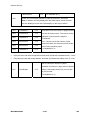
LEGEND
COMPANY
PRODUCT
CODE
LANIER
RICOH
SAVIN
M052
SP5200S
Aficio SP5200S
SP5200S
M053
SP5210SF
Aficio SP5210SF
SP5210SF
M054
SP5210SR
Aficio SP5210SR
SP5210SR
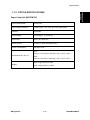
DOCUMENTATION HISTORY
REV. NO.
*
DATE
11/2011
COMMENTS
Original Printing
M052/M053/M054
TABLE OF CONTENTS
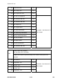
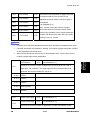
1. PRODUCT INFORMATION .......................................................... 1-1 1.1 SPECIFICATIONS ..................................................................................... 1-1 1.2 OVERVIEW................................................................................................ 1-2 1.2.1 MECHANICAL COMPONENT LAYOUT ........................................... 1-2 1.2.2 DRIVE LAYOUT ............................................................................... 1-3 1.2.3 PAPER PATH ................................................................................... 1-4 Standard Model (M052)/ Fax and 1 Bin Tray Unit Model (M053) ......... 1-4 Finisher Model (M054) ......................................................................... 1-5 1.3 MACHINE CONFIGURATION ................................................................... 1-6 1.3.1 MACHINE CONFIGURATION .......................................................... 1-6 Controller Devices ................................................................................ 1-8 2. INSTALLATION ............................................................................ 2-1 2.1 INSTALLATION REQUIREMENTS............................................................ 2-1 2.1.1 ENVIRONMENT ............................................................................... 2-1 2.1.2 MACHINE LEVEL ............................................................................. 2-1 2.1.3 MINIMUM OPERATIONAL SPACE REQUIREMENTS .................... 2-2 2.1.4 POWER REQUIREMENTS .............................................................. 2-2 2.2 OPTIONAL UNIT COMBINATIONS ........................................................... 2-3 2.2.1 MACHINE OPTIONS ........................................................................ 2-3 Fax Options .......................................................................................... 2-3 2.2.2 CONTROLLER AND OTHER OPTIONS .......................................... 2-4 Controller Options ................................................................................ 2-4 Other Options ....................................................................................... 2-4 2.3 COPIER ..................................................................................................... 2-5 2.3.1 ACCESSORY CHECK ...................................................................... 2-5 2.3.2 INSTALLATION PROCEDURE ........................................................ 2-6 Copier settings ..................................................................................... 2-6 Fax Settings only for M053 model ........................................................ 2-9 When Using an Smart Card Reader ..................................................... 2-9 2.3.3 METER CLICK CHARGE ............................................................... 2-11 2.4 PAPER FEED UNIT TK1090 (M375) ....................................................... 2-13 2.4.1 INSTALLATION PROCEDURE ...................................................... 2-13 SM
i
M052/M053/M054
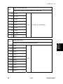
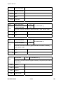
2.5 PAPER FEED UNIT TK1100 (M376) ....................................................... 2-15 2.5.1 INSTALLATION PROCEDURE ...................................................... 2-15 When installing the three units (M375 and M376) .............................. 2-17 2.6 FAX OPTION TYPE SP5200 (M381) ....................................................... 2-18 2.6.1 COMPONENT CHECK ................................................................... 2-18 2.6.2 INSTALLATION PROCEDURE ...................................................... 2-19 2.7 COPY DATA SECURITY UNIT TYPE F (B829)....................................... 2-23 2.7.1 COMPONENTS CHECK................................................................. 2-23 2.7.2 INSTALLATION .............................................................................. 2-24 User Tool Setting ............................................................................... 2-25 2.8 CONTROLLER OPTIONS ....................................................................... 2-26 2.8.1 OVERVIEW .................................................................................... 2-26 SD Card Slots .................................................................................... 2-26 I/F Card Slot ....................................................................................... 2-26 USB Slots ........................................................................................... 2-26 2.8.2 SD CARD APPLI MOVE ................................................................. 2-27 Overview ............................................................................................ 2-27 Move Exec ......................................................................................... 2-28 Undo Exec.......................................................................................... 2-29 2.8.3 FILE FORMAT CONVERTER (D377) ............................................. 2-30 Installation Procedure ........................................................................ 2-30 2.8.4 IEEE 802.11 A/G, G (D377: WIRELESS LAN) ............................... 2-31 Installation Procedure ........................................................................ 2-31 UP Mode Settings for Wireless LAN .................................................. 2-33 SP Mode and UP Mode Settings for IEEE 802.11 a/g, g Wireless LAN2-35 2.8.5 BLUETOOTH INTERFACE UNIT TYPE D (D566) ......................... 2-36 Installation Procedure ........................................................................ 2-36 2.8.6 BROWSER UNIT TYPE E (D430) .................................................. 2-37 Installation Procedure ........................................................................ 2-37 Update Procedure .............................................................................. 2-38 2.8.7 GIGABIT ETHERNET BOARD TYPE A (G874)/ TYPE C (M397) .. 2-39 Installation Procedure ........................................................................ 2-39 2.8.8 IPDS UNIT TYPE 5210 (D571) ....................................................... 2-40 Installation Procedure ........................................................................ 2-40 2.8.9 MEMORY UNIT TYPE B 32MB (G578) .......................................... 2-41 Installation Procedure ........................................................................ 2-41 2.8.10 CHECK ALL CONNECTIONS .................................................... 2-41 3. PREVENTIVE MAINTENANCE .................................................... 3-1 M052/M053/M054
ii
SM
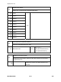
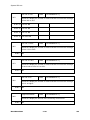
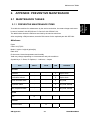
3.1 MAINTENANCE TABLES .......................................................................... 3-1 3.1.1 USER MAINTENANCE ..................................................................... 3-1 3.1.2 SERVICE MAINTENANCE ............................................................... 3-1 3.2 PM PARTS SETTINGS .............................................................................. 3-2 3.2.1 BEFORE REMOVING THE OLD PM PARTS ................................... 3-2 3.2.2 AFTER INSTALLING THE NEW PM PARTS ................................... 3-2 3.2.3 OPERATION CHECK ....................................................................... 3-2 4. REPLACEMENT AND ADJUSTMENT ........................................ 4-1 4.1 PRECAUTIONS ......................................................................................... 4-1 4.1.1 GENERAL......................................................................................... 4-1 AIO ....................................................................................................... 4-1 Transfer Roller ..................................................................................... 4-1 Scanner Unit ........................................................................................ 4-1 Laser Unit ............................................................................................. 4-2 Fusing Unit ........................................................................................... 4-2 Paper Feed .......................................................................................... 4-2 4.1.2 LITHIUM BATTERIES....................................................................... 4-2 4.1.3 HALOGEN-FREE CABLE ................................................................. 4-2 4.2 SPECIAL TOOLS AND LUBRICANTS ...................................................... 4-3 4.3 ADJUSTING COPY IMAGE AREA ............................................................ 4-4 4.3.1 PRINTING ......................................................................................... 4-4 Adjusting Registration .......................................................................... 4-4 Adjusting Blank Margin......................................................................... 4-6 Adjusting Main-Scan Magnification ...................................................... 4-7 4.3.2 SCANNING ....................................................................................... 4-7 Adjusting Registration .......................................................................... 4-7 Adjusting Magnification ........................................................................ 4-8 4.3.3 DF IMAGE ADJUSTMENT ............................................................... 4-9 4.4 EXTERIOR COVERS .............................................................................. 4-11 4.4.1 LEFT COVER ................................................................................. 4-11 4.4.2 RIGHT COVER ............................................................................... 4-12 4.4.3 REAR LOWER COVER .................................................................. 4-13 4.4.4 FRONT DOOR ................................................................................ 4-14 4.4.5 DUPLEX UNIT ................................................................................ 4-15 4.4.6 OPERATION PANEL UNIT ............................................................. 4-16 Operation Panel Unit .......................................................................... 4-16 Key Tops ............................................................................................ 4-18 4.4.7 TOUCH PANEL POSITION ADJUSTMENT ................................... 4-20 SM
iii
M052/M053/M054
4.4.8 OUTPUT TRAY (M052/M053 MODELS ONLY) ............................. 4-21 4.5 SCANNER UNIT ...................................................................................... 4-22 4.5.1 SCANNER FRONT COVER ........................................................... 4-22 4.5.2 SCANNER RIGHT AND LEFT COVERS ........................................ 4-23 Scanner Right Cover .......................................................................... 4-23 Scanner Left Cover ............................................................................ 4-23 4.5.3 SCANNER REAR COVER.............................................................. 4-24 4.5.4 EXPOSURE GLASS ....................................................................... 4-25 When reassembling the ARDF exposure glass .................................. 4-25 4.5.5 LED BOARD ................................................................................... 4-26 4.5.6 SCANNER MOTOR ........................................................................ 4-29 4.5.7 SENSOR BOARD UNIT (SBU) ....................................................... 4-30 When reassembling ........................................................................... 4-30 4.5.8 LED DRIVE BOARD ....................................................................... 4-31 4.5.9 SCANNER HP SENSOR ................................................................ 4-32 4.5.10 COVER SENSOR ....................................................................... 4-33 4.5.11 FRONT SCANNER WIRE........................................................... 4-34 Reinstalling the Front Scanner Wire ................................................... 4-35 4.5.12 REAR SCANNER WIRE ............................................................. 4-38 Reinstalling the Rear Scanner Wire ................................................... 4-39 4.6 LASER OPTICS ....................................................................................... 4-40 4.6.1 CAUTION DECAL LOCATIONS ..................................................... 4-40 4.6.2 SAFETY SWITCHES FOR LASER UNIT ....................................... 4-41 4.6.3 LASER UNIT ................................................................................... 4-41 Preparation before Removing the Laser Unit ..................................... 4-41 Removing the Laser Unit for All Models ............................................. 4-42 4.6.4 POLYGON MOTOR ........................................................................ 4-43 4.6.5 LASER SYNCHRONIZATION DETECTOR .................................... 4-44 4.7 PAPER TRANSFER ................................................................................ 4-45 4.7.1 TRANSFER ROLLER ..................................................................... 4-45 4.8 DRIVE SECTION ..................................................................................... 4-46 4.8.1 GEARBOX ...................................................................................... 4-46 4.8.2 MAIN MOTOR ................................................................................ 4-47 4.8.3 DUPLEX MOTOR ........................................................................... 4-48 4.8.4 BY-PASS FEED CLUTCH .............................................................. 4-49 4.8.5 RELAY CLUTCH ............................................................................ 4-49 4.8.6 PAPER FEED CLUTCH.................................................................. 4-50 4.8.7 REGISTRATION CLUTCH ............................................................. 4-50 M052/M053/M054
iv
SM
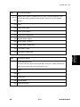
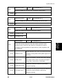
4.9 PAPER FEED .......................................................................................... 4-51 4.9.1 PAPER FEED ROLLER .................................................................. 4-51 4.9.2 FRICTION PAD .............................................................................. 4-52 When reassembling the friction pad ................................................... 4-52 4.9.3 PAPER END SENSOR ................................................................... 4-53 4.9.4 REMAINING PAPER SENSORS .................................................... 4-53 4.9.5 REGISTRATION SENSOR ............................................................. 4-54 4.9.6 BY-PASS PAPER SENSOR ........................................................... 4-54 4.9.7 DUPLEX RELAY SENSOR ............................................................. 4-55 When reassembling the duplex relay sensor...................................... 4-55 4.9.8 JUNCTION GATE 1 SOLENOID .................................................... 4-56 4.9.9 JUNCTION GATE 2 SOLENOID .................................................... 4-57 4.9.10 FUSING EXIT SENSOR (M053 MODEL ONLY) ........................ 4-58 4.9.11 PAPER OVERFLOW SENSOR (M052/M053 MODELS ONLY) . 4-58 4.10 FUSING.............................................................................................. 4-59 4.10.1 FUSING UNIT ............................................................................. 4-59 4.10.2 HOT ROLLER AND PRESSURE ROLLER SECTIONS ............. 4-60 4.10.3 FUSING LAMP ........................................................................... 4-61 4.10.4 HOT ROLLER ............................................................................. 4-62 4.10.5 FUSING THERMISTOR ............................................................. 4-63 4.10.6 THERMOSTATS......................................................................... 4-63 4.10.7 PRESSURE ROLLER ................................................................. 4-64 4.10.8 FUSING CLEANING ROLLER.................................................... 4-64 4.11 DUPLEX UNIT ................................................................................... 4-65 4.11.1 DUPLEX UNIT ............................................................................ 4-65 4.11.2 DUPLEX INVERTER MOTOR .................................................... 4-66 4.11.3 DUPLEX EXHAUST FAN ........................................................... 4-67 4.11.4 DUPLEX INVERTER SENSOR .................................................. 4-69 4.11.5 DUPLEX ENTRANCE SENSOR................................................. 4-70 4.12 ELECTRICAL COMPONENTS .......................................................... 4-71 4.12.1 CONTROLLER UNIT .................................................................. 4-71 4.12.2 HDD UNIT................................................................................... 4-72 4.12.3 HDD CONTROL BOARD ............................................................ 4-73 4.12.4 NVRAM ....................................................................................... 4-73 When reinstalling a new NVRAM ....................................................... 4-74 4.12.5 EEPROMS .................................................................................. 4-76 When reinstalling a new EEPROM ..................................................... 4-76 4.12.6 DIMM RAM ................................................................................. 4-77 SM
v
M052/M053/M054
4.12.7 CONTROLLER BOARD ............................................................. 4-78 When installing a new controller board............................................... 4-79 4.12.8 BICU ........................................................................................... 4-80 BICU................................................................................................... 4-80 BICU Bracket ..................................................................................... 4-81 4.12.9 HVPS (HIGH VOLTAGE POWER SUPPLY) .............................. 4-83 4.12.10 RFID BOARD............................................................................ 4-83 4.12.11 TONER END SENSOR ............................................................ 4-84 4.12.12 PAPER SIZE SENSOR BOARD ............................................... 4-84 4.12.13 PSU .......................................................................................... 4-85 4.13 ARDF ................................................................................................. 4-87 4.13.1 ARDF .......................................................................................... 4-87 When installing the Platen Sheet ....................................................... 4-88 4.13.2 ARDF REAR COVER ................................................................. 4-88 4.13.3 ARDF FRONT COVER AND ORIGINAL TRAY .......................... 4-89 4.13.4 ORIGINAL FEED UNIT ............................................................... 4-90 4.13.5 PICK-UP ROLLER ...................................................................... 4-91 4.13.6 FEED ROLLER ........................................................................... 4-92 4.13.7 ARDF FRICTION PAD ................................................................ 4-93 4.13.8 ARDF DRIVE BOARD ................................................................ 4-94 4.13.9 ORIGINAL SET SENSOR AND ARDF TOP COVER SENSOR . 4-95 4.13.10 ARDF FEED MOTOR ............................................................... 4-97 4.13.11 ARDF FEED CLUTCH .............................................................. 4-98 4.13.12 ARDF TRANSPORT MOTOR................................................... 4-99 4.13.13 ARDF REGISTRATION SENSOR .......................................... 4-101 4.13.14 ARDF INVERTER SENSOR ................................................... 4-102 4.13.15 ARDF COOLING FAN ............................................................ 4-103 When installing the cooling fan ......................................................... 4-103 4.14 INTERNAL FINISHER ...................................................................... 4-104 4.14.1 INTERNAL FINISHER .............................................................. 4-104 When reinstalling the internal finisher .............................................. 4-105 4.14.2 FINISHER OUTPUT TRAY UNIT ............................................. 4-106 4.14.3 STAPLER UNIT ........................................................................ 4-107 4.14.4 GATHERING ROLLER MOTOR ............................................... 4-108 4.14.5 4.14.6 4.14.7 4.14.8 FINISHER PAPER EXIT MOTOR............................................. 4-109 SHIFT ROLLER MOTOR .......................................................... 4-110 FINISHER TRANSPORT MOTOR ............................................ 4-111 TRAY LIFT MOTOR ................................................................. 4-112 M052/M053/M054
vi
SM
4.14.9 JOGGER FENCE HP SENSOR ............................................... 4-113 4.14.10 JOGGER MOTOR .................................................................. 4-115 4.14.11 EXIT GUIDE PLATE MOTOR ................................................. 4-116 4.14.12 SHIFT ROLLER HP SENSOR ................................................ 4-117 4.14.13 GATHERING ROLLER HP SENSOR ..................................... 4-118 4.14.14 FINISHER ENTRANCE SENSOR .......................................... 4-119 4.14.15 FINISHER EXIT SENSOR ...................................................... 4-120 4.14.16 FINISHER PAPER SENSOR .................................................. 4-122 4.14.17 STAPLE TRAY PAPER SENSOR .......................................... 4-123 4.14.18 TRAY LOWER LIMIT SENSOR .............................................. 4-124 4.14.19 EXIT GUIDE PLATE HP SENSOR ......................................... 4-124 4.14.20 FINISHER MAIN BOARD ....................................................... 4-125 When reinstalling a new finisher main board .................................... 4-125 4.15 1 BIN TRAY UNIT ............................................................................ 4-126 4.15.1 1 BIN TRAY UNIT ..................................................................... 4-126 4.15.2 1 BIN TRAY PAPER EXIT SENSOR ........................................ 4-130 4.15.3 1 BIN TRAY PAPER SENSOR AND LED BOARD ................... 4-131 5. SYSTEM MAINTENANCE REFERENCE..................................... 5-1 5.1 SERVICE PROGRAM ................................................................................ 5-1 5.1.1 USING SP AND SSP MODES .......................................................... 5-1 5.1.2 TYPES OF SP MODES .................................................................... 5-1 SP Mode Button Summary ................................................................... 5-2 Switching Between SP Mode and Copy Mode for Test Printing ........... 5-3 Selecting the Program Number ............................................................ 5-3 Exiting Service Mode............................................................................ 5-4 Service Mode Lock/Unlock ................................................................... 5-4 5.1.3 REMARKS ........................................................................................ 5-5 Display on the Control Panel Screen ................................................... 5-5 Others .................................................................................................. 5-6 5.2 SYSTEM SP1-XXX .................................................................................... 5-7 5.2.1 SP1-XXX (FEED) .............................................................................. 5-7 5.3 SYSTEM SP2-XXX .................................................................................. 5-13 5.3.1 SP2-XXX (DRUM)........................................................................... 5-13 5.4 SYSTEM SP3-XXX .................................................................................. 5-15 5.4.1 SP3-XXX (PROCESS) .................................................................... 5-15 5.5 SYSTEM SP4-XXX .................................................................................. 5-16 5.5.1 SP4-XXX (SCANNER) .................................................................... 5-16 5.6 SYSTEM SP5-XXX .................................................................................. 5-34 SM
vii
M052/M053/M054
5.6.1 SP5-XXX (MODE) .......................................................................... 5-34 5.7 SYSTEM SP6-XXX ................................................................................ 5-102 5.7.1 SP6-XXX (PERIPHERALS) .......................................................... 5-102 5.8 SYSTEM SP7-XXX ................................................................................ 5-105 5.8.1 SP7-XXX (DATA LOG) ................................................................. 5-105 5.9 SYSTEM SP8-XXX ................................................................................ 5-116 5.9.1 SP8-XXX: DATA LOG2................................................................. 5-116 5.10 INPUT AND OUTPUT CHECK ......................................................... 5-164 5.10.1 INPUT CHECK TABLE ............................................................. 5-164 Mianframe ........................................................................................ 5-164 ARDF ............................................................................................... 5-168 Internal Finisher ............................................................................... 5-169 5.10.2 OUTPUT CHECK TABLE ......................................................... 5-170 Copier............................................................................................... 5-170 ARDF ............................................................................................... 5-172 Internal Finisher ............................................................................... 5-173 5.11 PRINTER SERVICE MODE ............................................................. 5-174 5.11.1 SP1-XXX (SERVICE MODE) .................................................... 5-174 5.12 SCANNER SERVICE MODE ........................................................... 5-183 5.12.1 SP1-XXX (SYSTEM AND OTHERS) ........................................ 5-183 5.12.2 SP2-XXX (SCANNING-IMAGE QUALITY) ............................... 5-185 5.13 FAX SERVICE MODE ...................................................................... 5-186 5.14 FIRMWARE UPDATE ...................................................................... 5-187 5.14.1 TYPE OF FIRMWARE .............................................................. 5-187 5.14.2 BEFORE YOU BEGIN .............................................................. 5-189 5.14.3 UPDATING FIRMWARE ........................................................... 5-190 Preparation....................................................................................... 5-190 Updating Procedure ......................................................................... 5-190 Error Messages ................................................................................ 5-191 Firmware Update Error ..................................................................... 5-191 Recovery after Power Loss .............................................................. 5-192 5.14.4 UPDATE PROCEDURE FOR APP2ME PROVIDER ................ 5-193 5.14.5 BROWSER UNIT UPDATE PROCEDURE............................... 5-194 5.14.6 HANDLING FIRMWARE UPDATE ERRORS ........................... 5-195 Error Message Table ........................................................................ 5-195 5.15 SD CARD APPLI MOVE .................................................................. 5-197 5.15.1 OVERVIEW .............................................................................. 5-197 Outline of SD Card Appli Move: ....................................................... 5-197 M052/M053/M054
viii
SM
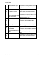
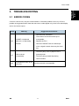
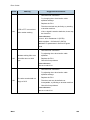
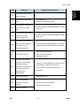
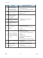
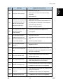
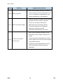
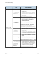
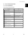
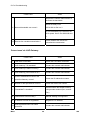
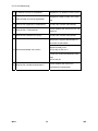
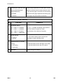
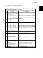
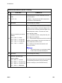
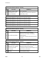
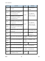
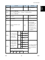
5.15.2 MOVE EXEC ............................................................................ 5-198 5.15.3 UNDO EXEC ............................................................................ 5-199 5.16 NVRAM DATA UPLOAD/DOWNLOAD ............................................ 5-200 5.16.1 UPLOADING CONTENT OF NVRAM TO AN SD CARD ......... 5-200 5.16.2 DOWNLOADING AN SD CARD TO NVRAM ........................... 5-201 5.17 CARD SAVE FUNCTION ................................................................. 5-202 5.17.1 OVERVIEW .............................................................................. 5-202 Card Save: ....................................................................................... 5-202 5.17.2 PROCEDURE ........................................................................... 5-203 5.17.3 ERROR MESSAGES ................................................................ 5-205 5.18 USING SP MODES .......................................................................... 5-206 5.18.1 ADJUSTING REGISTRATION AND MAGNIFICATION ............ 5-206 5.18.2 TEST PATTERN PRINT (SP 5902) .......................................... 5-206 Executing Test Pattern Printing ........................................................ 5-206 Test Patterns .................................................................................... 5-206 5.18.3 SMC PRINT (SP 5990) ............................................................. 5-208 6. TROUBLESHOOTING ................................................................. 6-1 6.1 SERVICE CALL CONDITIONS .................................................................. 6-1 6.1.1 SUMMARY ....................................................................................... 6-1 6.1.2 SC CODE DESCRIPTIONS .............................................................. 6-2 SC1xx: Scanning .................................................................................. 6-3 SC2xx: Laser Exposure........................................................................ 6-6 SC3xx: Image Processing – 1 .............................................................. 6-8 SC4xx: Image Processing - 2 ............................................................... 6-8 SC5xx: Paper Feed and Fusing ........................................................... 6-9 SC6xx: Device Communication .......................................................... 6-12 SC7xx: Peripherals ............................................................................ 6-17 SC8xx: Controller ............................................................................... 6-20 SC9xx: Others .................................................................................... 6-28 6.2 ELECTRICAL COMPONENT DEFECTS ................................................. 6-32 6.2.1 BLOWN FUSE CONDITIONS ......................................................... 6-32 Power Supply Unit .............................................................................. 6-32 6.3 JAM DETECTION .................................................................................... 6-33 6.3.1 PAPER JAM DISPLAY ................................................................... 6-33 6.3.2 JAM CODES AND DISPLAY CODES............................................. 6-33 Paper Jam Detection Sensor Location ............................................... 6-39 7. ENERGY SAVING ........................................................................ 7-1 SM
ix
M052/M053/M054
7.1 ENERGY SAVE ......................................................................................... 7-1 7.1.1 ENERGY SAVER MODES ............................................................... 7-1 Timer Settings ...................................................................................... 7-1 Return to Stand-by Mode ..................................................................... 7-2 Recommendation ................................................................................. 7-2 7.1.2 ENERGY SAVE EFFECTIVENESS .................................................. 7-2 7.2 PAPER SAVE ............................................................................................ 7-4 7.2.1 EFFECTIVENESS OF DUPLEX/COMBINE FUNCTION .................. 7-4 1. Duplex: ............................................................................................. 7-4 2. Combine mode: ................................................................................ 7-4 3. Duplex + Combine: ........................................................................... 7-4 How to calculate the paper reduction ratio ........................................... 7-5 M052/M053/M054 SERVICE MANUAL APPENDICES
SEE M052/M053/M054 SERVICE MANUAL APPENDICES SECTION FOR DETAILED TABLE
OF CONTENTS
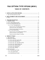
FAX OPTION TYPE SP5200 (M381)
SEE M381 SECTION FOR DETAILED TABLE OF CONTENTS
PAPER FEED UNIT TK1090/TK1100/TK1120/TK1130
(M375/M376/M386/M389)
SEE M375/M376/M386/M389 SECTION FOR DETAILED TABLE OF CONTENTS
M052/M053/M054
x
SM
READ THIS FIRST
Safety Notices
Important Safety Notices
Prevention of Physical Injury
1.
Before disassembling or assembling parts of the machine and peripherals, make sure that
the machine power cord is unplugged.
2.
The wall outlet should be near the machine and easily accessible.
3.
If any adjustment or operation check has to be made with exterior covers off or open while
the main switch is turned on, keep hands away from electrified or mechanically driven
components.
4.
The machine drives some of its components when it completes the warm-up period. Be
careful to keep hands away from the mechanical and electrical components as the machine
starts operation.
5.
The inside and the metal parts of the fusing unit become extremely hot while the machine is
operating. Be careful to avoid touching those components with your bare hands.
Health Safety Conditions
Toner is non-toxic, but if you get either of them in your eyes by accident, it may cause temporary
eye discomfort. Try to remove with eye drops or flush with water as first aid. If unsuccessful, get
medical attention.
Observance of Electrical Safety Standards
The machine and its peripherals must be serviced by a customer service representative who
has completed the training course on those models.
The Controller board on this machine contains a lithium battery. The danger of explosion
exists if a battery of this type is incorrectly replaced. Replace only with the same or an
equivalent type recommended by the manufacturer. Discard batteries in accordance with
the manufacturer's instructions and local regulations.
The optional fax and memory expansion units contain lithium batteries, which can explode
if replaced incorrectly. Replace only with the same or an equivalent type recommended by
the manufacturer. Do not recharge or burn the batteries. Used batteries must be handled in
accordance with local regulations.
Safety and Ecological Notes for Disposal
1.
Do not incinerate toner bottles or used toner. Toner dust may ignite suddenly when
exposed to an open flame.
2.
Dispose of used toner, the maintenance unit which includes developer or the organic
photoconductor in accordance with local regulations. (These are non-toxic supplies.)
3.
Dispose of replaced parts in accordance with local regulations.
To prevent a fire or explosion, keep the machine away from flammable liquids, gases,
and aerosols. A fire or an explosion might occur.
Lithium Batteries
Incorrect replacement of lithium battery(s) on the FCU, controller board and memory board unit
may pose risk of explosion. Replace only with the same type or with an equivalent type
recommended by the manufacturer. Discard used batteries in accordance with the
manufacturer's instructions.
Laser Safety
The Center for Devices and Radiological Health (CDRH) prohibits the repair of laser-based
optical units in the field. The optical housing unit can only be repaired in a factory or at a
location with the requisite equipment. The laser subsystem is replaceable in the field by a
qualified Customer Engineer. The laser chassis is not repairable in the field. Customer
engineers are therefore directed to return all chassis and laser subsystems to the factory or
service depot when replacement of the optical subsystem is required.
Use of controls, or adjustment, or performance of procedures other than those
specified in this manual may result in hazardous radiation exposure.
WARNING
WARNING:
Turn off the main switch before attempting any of the procedures in the Laser Optics
Housing Unit section. Laser beams can seriously damage your eyes.
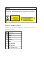
CAUTION MARKING:
Symbols and Abbreviations
This manual uses several symbols and abbreviations. The meaning of those symbols and
abbreviations is as follows:
See or Refer to
Clip ring
E-ring
Screw
Connector
Clamp
SEF
Short Edge Feed
LEF
Long Edge Feed
-
Core Technology manual
Cautions, Notes, etc.
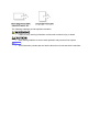
The following headings provide special information:
Failure to obey warning information could result in serious injury or death.
Obey these guidelines to ensure safe operation and prevent minor injuries.
This information provides tips and advice about how to best service the machine.
PRODUCT INFORMATION
R E V I S I O N H I S T O RY
P a ge
Date
A d de d /U pd at e d /N ew
None
Specifications
Product
Information
1. PRODUCT INFORMATION
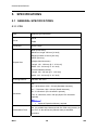
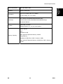
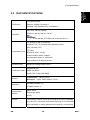
1.1 SPECIFICATIONS
See "Appendices" for the following information:
General Specifications
Supported Paper Sizes
SM
1-1
M052/M053/M054
Overview
1.2 OVERVIEW
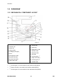
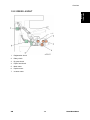
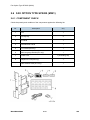
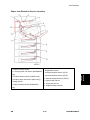
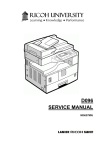
1.2.1 MECHANICAL COMPONENT LAYOUT
1. Scanner unit
2. Laser unit
3. Charge roller
4. Cartridge (AIO-type)
5. Drum
6. Development roller
7. By-pass feed tray
8. By-pass feed roller
9. Paper feed roller
10. Friction pad
11. Paper tray
12. Registration roller
13. Transfer roller
14. Pressure roller
15. Hot roller
16. Junction gate 1*1
17. Paper exit roller*2
18. Junction gate 2*3
19. Inverter roller
*1: Junction gate 1 is not movable for the finisher model (M054).
*2: Paper exit roller is not used for the finisher model (M054).
*3: Junction gate 2 is not movable for the standard model (M052).
M052/M053/M054
1-2
SM
Overview
Product
Information
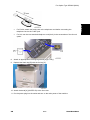
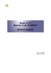
1.2.2 DRIVE LAYOUT
1.
Registration clutch
2.
Relay clutch
3.
By-pass clutch
4.
Paper feed clutch
5.
Main motor
6.
Duplex motor
7.
Inverter motor
SM
1-3
M052/M053/M054
Overview
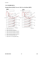
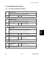
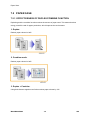
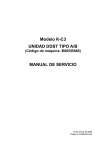
1.2.3 PAPER PATH
Standard Model (M052)/ Fax and 1 Bin Tray Unit Model (M053)
1.
Paper feed from tray 1
2.
Paper feed from by-pass tray
3.
Paper feed from optional PFU (tray2)
4.
Paper feed from optional PFU (tray3)
5.
Paper feed from optional PFU (tray4)
6.
Paper feed through duplex unit
7.
Paper exit to 1 bin tray (M053 only)
M052/M053/M054
1-4
SM
Overview
Product
Information
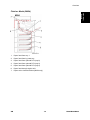
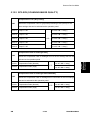
Finisher Model (M054)
1.
Paper feed from tray 1
2.
Paper feed from by-pass tray
3.
Paper feed from optional PFU (tray2)
4.
Paper feed from optional PFU (tray3)
5.
Paper feed from optional PFU (tray4)
6.
Paper feed through duplex unit
7.
Paper exit to internal finisher (M054 only)
SM
1-5
M052/M053/M054
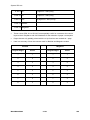
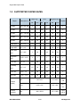
Machine Configuration
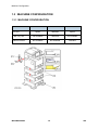
1.3 MACHINE CONFIGURATION
1.3.1 MACHINE CONFIGURATION
M052
M053
M054
Option
Standard
Option
1 Bin Tray Unit
Not available
Standard
Not available
Internal Finisher
Not available
Not available
Standard
Fax Unit
M052/M053/M054
1-6
SM
Item
Machine Code
Product
Information
Machine Configuration
Remarks
Main Unit [A]
M052
Standard model
Main Unit [B]
M053
Fax and 1 bin tray unit model
Main Unit [C]
M054
Finisher model
Paper Feed Unit TK1090 [D]
M375
Option
Paper Feed Unit TK1100 [E]
M376
Option
Fax Option Type SP5200 [F]
M381
Memory Unit Type B [G]
G578
SM
1-7
Standard for M053
Option for M052 and M054
SAF memory:
Requires the Fax Option.
M052/M053/M054
Machine Configuration
Controller Devices
Item
Machine Code
Remarks
VM Card [E]
-
Standard
Security Card [D]
-
Standard
Copy Data Security Unit Type
F [G]
Remote Communication Gate
A
IPDS Unit Type 5210 [D]
B829
Option
D459
Option
D571
Controller Option
Gigabit Ethernet Board Type
Type A: G874
A/ Type C [A]
Type C: M397
IEEE802.11 a/g Interface Unit
Type J, K [B]
Browser Unit Type E [E]
File Format Converter Type E
[C]
Bluetooth Interface Unit Type
D [F]
M052/M053/M054
Controller Option
D377
Controller Option
D430
Controller Option
D377
Controller Option
D566
Controller Option
1-8
SM
INSTALLATION
R E V I S I O N H I S T O RY
P a ge
Date
A d de d /U pd at e d /N ew
None
Installation Requirements
2. INSTALLATION
2.1 INSTALLATION REQUIREMENTS
Installation
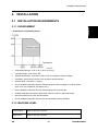
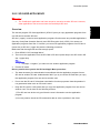
2.1.1 ENVIRONMENT
–Temperature and Humidity Chart–
Temperature Range: 10°C to 32°C (50°F to 89.6°F)
Humidity Range: 15% to 80% RH
Ambient Illumination: Less than 1,500 lux (Do not expose to direct sunlight.)
Ventilation: Room air should turn over at least 3 times/hr/person
Ambient Dust: Less than 0.1 mg/m3
Do not install the machine where it will be exposed to direct sunlight or to direct airflow
(from a fan, air conditioner, air cleaner, etc.).
Do not install the machine where it will be exposed to corrosive gas.
Install the machine at locations lower than 2,000 m (6,560 ft.) above sea level.
Place the machine on a firm and level base.
Do not install the machine where it may be subjected to strong vibration.
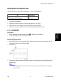
2.1.2 MACHINE LEVEL
Front to back:
Within 5 mm (0.2") of level
Right to left:
Within 5 mm (0.2") of level
SM
2-1
M052/M053/M054
Installation Requirements
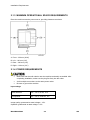
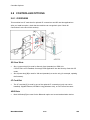
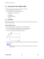
2.1.3 MINIMUM OPERATIONAL SPACE REQUIREMENTS
Place the machine near the power source, providing clearance as shown.
A: Front – 350 mm (29.6")
B: Left – 100 mm (3.9")
C: Rear – 300 mm (3.9")
D: Right – 100 mm (3.9")
2.1.4 POWER REQUIREMENTS
Make sure that the wall outlet is near the machine and easily accessible. After
completing installation, make sure the plug fits firmly into the outlet.
Avoid multiple connections to the same power outlet.
Be sure to ground the machine.
Input voltage:
North America:
120 – 127 V, 60 Hz, 12 A
Europe/Asia:
220 – 240 V, 50/60 Hz, 8 A
Image quality guaranteed at rated voltage ± 10%.
Operation guaranteed at rated voltage ± 15%.
M052/M053/M054
2-2
SM
Optional Unit Combinations
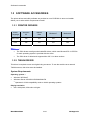
2.2 OPTIONAL UNIT COMBINATIONS
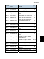
Installation
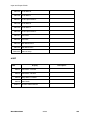
2.2.1 MACHINE OPTIONS
No.
Options
1
Paper Feed Unit TK1090
2
Paper Feed Unit TK1100
Remarks
Two units can be installed in the
mainframe.
This unit has casters.
Fax Options
No.
SM
Options
3
Fax Option Type SP5200
4
Memory Unit Type B
Remarks
Standard for M053
Options for M052/M054
SAF memory:
Requires the fax option.
2-3
M052/M053/M054
Optional Unit Combinations
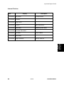
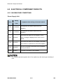
2.2.2 CONTROLLER AND OTHER OPTIONS
Controller Options
No.
Options
Remarks
1
IPDS Unit Type 5210
SD slot 1 (upper)
2
Browser Unit Type E
3
Bluetooth Interface Unit Type D
4
Gigabit Ethernet Board Type A/ Type C
5
IEEE802.11 a/g Interface Unit Type J, K
6
File Format Converter Type E
SD slot 2 (lower) during
installation only
One of USB slots
IF slot (one from three
options)
Other Options
No.
Options
Remarks
7
Copy Data Security Unit Type F
-
-
Remote Communication Gate A
-
M052/M053/M054
2-4
SM
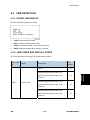
Copier
2.3 COPIER
Description
Q’ty
AIO
1
Power Cord
1
VM Card
1
Extender (finisher support tray; M054 only)
1
Paper Size and Tray Decals
1
Warranty Sheet (NA only)
1
User Registration Card (NA only)
1
Help Desk Card (NA only)
1
EULA (16 languages)
1
SM
2-5
M052/M053/M054
Installation
2.3.1 ACCESSORY CHECK
Copier
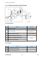
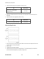
2.3.2 INSTALLATION PROCEDURE
Make sure that the copier remains unplugged during installation.
Copier settings
1.
Remove the plastic bag.
2.
Lift the machine by the inset grips on its sides.
At least four people are needed to lift the machine.
3.
Lower the machine slowly and carefully to prevent trapping your hands.
4.
Remove the adhesive tape attached on the machine's exterior.
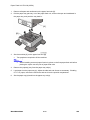
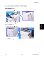
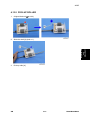
5.
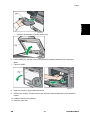
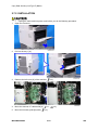
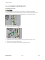
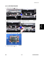
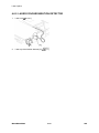
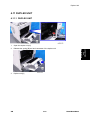
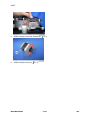
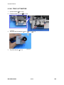
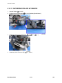
Only for M054 model, do the following steps from 1) and 2).
1) Pull out tray 1 [A], and then remove the extender [B] for the internal finisher from tray
1.
M052/M053/M054
2-6
SM
Installation
Copier
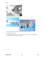
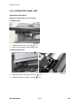
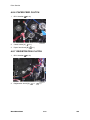
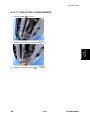
6.
2) Attach the extender [A] to the finisher tray.
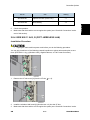
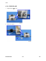
Lift the ARDF [A], and then remove the protective materials attached on the exposure
glass.
7.
Close the ARDF.
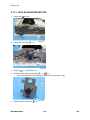
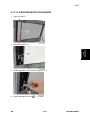
8.
Open the front door [A] pressing the button.
9.
Remove the AIO [B], and then remove the protective material attached on the machine's
interior.
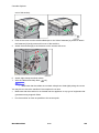
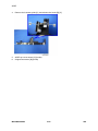
10. Install the AIO into the machine.
11. Close the front door.
SM
2-7
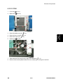
M052/M053/M054
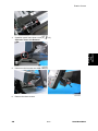
Copier
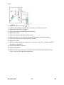
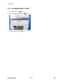
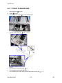
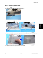
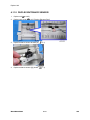
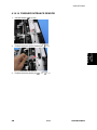
12. Remove the SD slot cover [A] (
x 1).
13. Install the VM card [B] provided in the accessories in the SD slot 2 (lower).
14. Attach the SD slot cover [A] (
x 1).
15. Plug in the machine, and then turn on the machine.
16. Start the SP mode.
17. Select SP5-302-002 and specify the time zone.
18. Select SP5-307-001, 003, and 004 and specify the daylight-saving-time settings.
19. Exit the SP mode and turn the main switch off and on.
20. Start the UP mode.
21. Specify the date and time with "Set Date" or "Set Time" (User Tool" > "System Settings" >
"Set Date" or "Set Time").
22. Turn the main switch off and on.
23. Check the operations.
24. Make a full size copy, and check if the side-to-side and leading edge registrations are
correct. If they are not, adjust the registrations.
M052/M053/M054
2-8
SM
Copier
Fax Settings only for M053 model
Initializing the Fax unit
When you press the Fax key for the first time after installation, the error "SRAM problem
occurred / SRAM was formatted" will show on the LCD for initializing the program of the fax unit.
If another error occurs after initialization, this can be a functional problem.
1.
Select fax SP1-101-016 and specify the country code.
2.
Select fax SP3-101-001 and specify the service station.
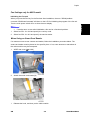
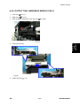
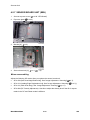
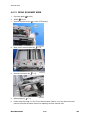
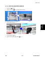
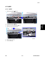
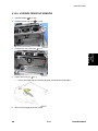
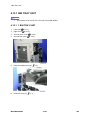
When Using an Smart Card Reader
If a customer wants to use a smart card reader, follow the installation procedure below. The
smart card reader must be placed on the specific place. If not, some antenna or transmitter in
the main machine may be interrupted.
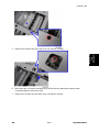
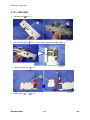
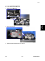
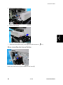
1.
ARDF rear cover (
2.
Attach the smart card reader [A].
1.
Release the hook, and then put the cable outside.
SM
p.4-88)
2-9
M052/M053/M054
Installation
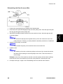
Turn the main power switch off/on to clear the error display.
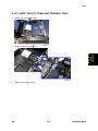
Copier
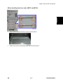
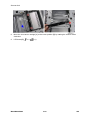
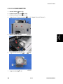
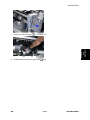
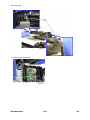
2.
Route the cable [A] as shown above.
3.
Remove the part [A] of the ARDF rear cover with nippers or a similar tool.
4.
Reassemble the machine.
5.
For details about connecting a smart card device to the machine, refer to the installation
procedure provided with the smart card device.
M052/M053/M054
2-10
SM
Copier
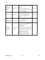
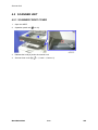
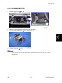
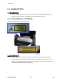
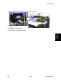
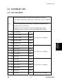
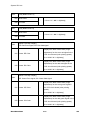
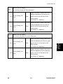
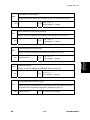
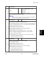
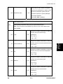
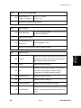
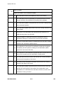
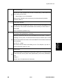
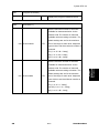
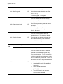
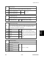
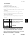
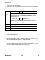
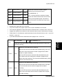
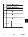
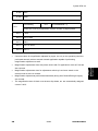
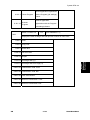
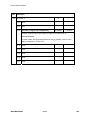
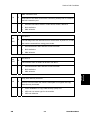
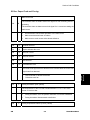
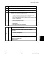
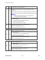
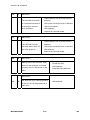
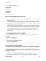
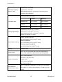
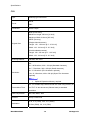
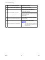
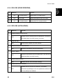
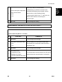
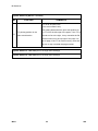
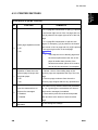
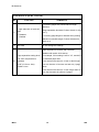
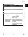
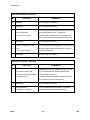
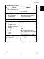
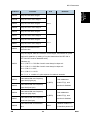
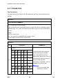
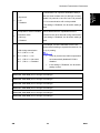
2.3.3 METER CLICK CHARGE
Basically, there are two ways to set up this function.
Meter click charge enabled (SP 5-930-001 set to "enabled") and Parts replacement
operation type enabled (SP5-067-001 set to "0: Service"): The counter can be displayed and
counter.
Meter click charge disabled (SP 5-930-001 set to "disabled"; this is the default setting)
and Parts replacement operation type enabled (SP5-067-001 set to "1: User", this is the
default setting): The counter cannot be displayed or printed by the customer. To check the
counter, the technician must print the SMC report (SP 5-990).
You must select one of the counter methods (developments/prints) in accordance with
the contract by using SP5-045-001.
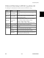
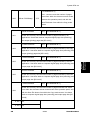
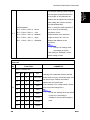
Item
SP No.
Function
Default
Enables or disables Meter Click
Charge.
When enabled:
The counter menu shows
immediately after you push the
Meter Click
Charge Setting
"Menu" key. The "Counter
Method" (SP5-045) sets the
SP5-930-001
"0": OFF
type of the counter.
You can print the counter from
the counter menu.
When disabled:
The counter menu does not
show.
Enables or disables the PM alert for
the maintenance kit.
Meter Click
Charge: Life
Disp:
Maintenance Kit
SP5-930-002
If this SP is enabled, an alert
message is displayed when the
"1": No alert
maintenance kit needs to be
replaced.
SM
2-11
M052/M053/M054
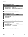
Installation
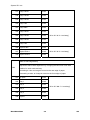
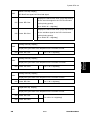
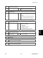
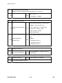
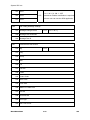
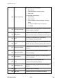
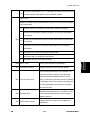
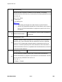
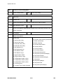
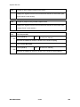
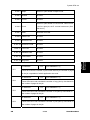
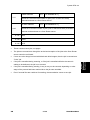
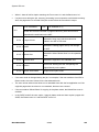
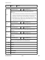
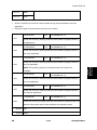
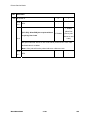
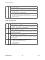
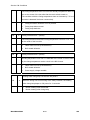
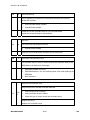
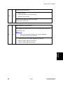
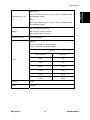
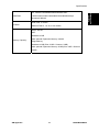
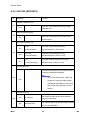
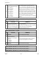
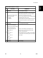
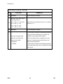
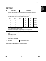
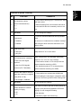
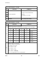
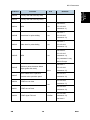
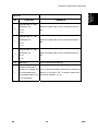
printed by the customer. The technician can then call the customer and ask them to read the
Copier
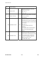
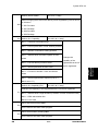
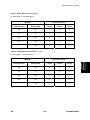
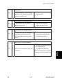
Enables or disables the PM alert for
the AIO.
Meter Click
Charge: Life
SP5-930-003
If this SP is enabled, an alert
"1": No alert
message is displayed when the AIO
Disp:AIO
needs to be replaced.
Specifies if the counting method
Counter method
SP5-045-001
used in meter charge mode is
based on develaibopments or
“1”: Prints
prints.
Parts
Replacement
Selects the service maintenance or
SP5-067-001
Operation Type
user maintenance for the
"1: User "
maintenance kit.
-001: shows or sets the telephone
number of the service
representative.
Service Tel:
Telephone
/Facsimile
SP5-812-001
and -002
-002: shows or sets the fax number
of the service station. The number
-
is printed on the counter list when
the "Meter Click Charge" is
enabled. User can send a fax
message with the counter list.
M052/M053/M054
2-12
SM
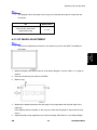
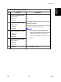
Paper Feed Unit TK1090 (M375)
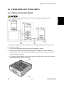
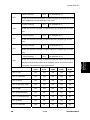
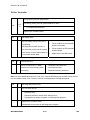
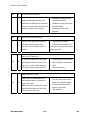
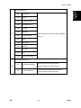
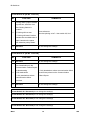
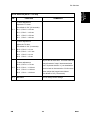
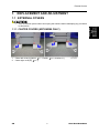
2.4 PAPER FEED UNIT TK1090 (M375)
Unplug the main machine's power cord before starting the following procedure.
The number of optional paper feed units that can be attached depends on the location where
the machine is installed.
[A]: Only one paper feed unit (M375 [D]) can be installed on a desk.
[B]: Up to three units (M375 [D] and M376 [E]) can be installed on the floor. Attach the
optional paper feed unit with casters (M376 [E]) to the bottom of the machine to install the
machine directly on the floor.
[C]: Attach the optional paper feed unit with casters (M376 [E]) to the bottom of the machine
to install the machine directly on the floor.
SM
2-13
M052/M053/M054
Installation
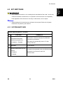
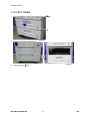
2.4.1 INSTALLATION PROCEDURE
Paper Feed Unit TK1090 (M375)
1.
Remove all tapes and cardboard on the paper feed unit [A].
2.
Pull the paper tray part way out of the paper feed unit, remove the tape and cardboard in
the paper tray, and push the tray back in.
3.
Set the machine [A] on the paper feed unit [B].
Two people are required to lift the machine.
When installing a second paper feed unit, place on the first paper feed unit before
placing the copier onto the pair of paper feed units
4.
Remove the paper(s) tray from the paper tray unit(s).
5.
Load paper into the paper tray(s). Adjust the side and end fences as necessary. If loading
81/2"x 14" paper, remove the end fence and set it into the special compartment.
6.
Set the paper tray(s) back into the paper tray unit(s).
M052/M053/M054
2-14
SM
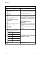
Paper Feed Unit TK1100 (M376)
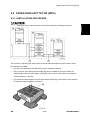
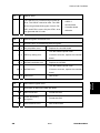
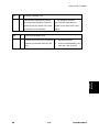
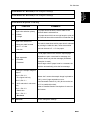
2.5 PAPER FEED UNIT TK1100 (M376)
Unplug the main machine's power cord before starting the following procedure.
The number of optional paper feed units that can be attached depends on the location where
the machine is installed.
[A]: Only one paper feed unit (M375 [D]) can be installed on a desk.
[B]: Up to three units (M375 [D] and M376 [E]) can be installed on the floor. Attach the
optional paper feed unit with casters (M376 [E]) to the bottom of the machine to install the
machine directly on the floor.
[C]: Attach the optional paper feed unit with casters (M376 [E]) to the bottom of the machine
to install the machine directly on the floor.
SM
2-15
M052/M053/M054
Installation
2.5.1 INSTALLATION PROCEDURE
Paper Feed Unit TK1100 (M376)
1.
Remove all tapes and cardboard on the paper feed unit [A].
2.
Pull the paper tray part way out of the paper feed unit, remove the tape and cardboard in
the paper tray, and push the tray back in.
3.
Set the machine [A] on the paper feed unit [B].
Two people are required to lift the machine.
When installing a second paper feed unit, place on the first paper feed unit before
placing the copier onto the pair of paper feed units
4.
Remove the paper(s) tray from the paper tray unit(s).
5.
Load paper into the paper tray(s). Adjust the side and end fences as necessary. If loading
81/2"x 14" paper, remove the end fence and set it into the special compartment.
6.
Set the paper tray(s) back into the paper tray unit(s).
M052/M053/M054
2-16
SM
Paper Feed Unit TK1100 (M376)
Installation
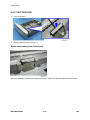
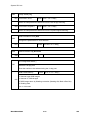
When installing the three units (M375 and M376)
1.
Attach the six brackets and six screws as shown above.
2.
Attach the screws into the paper feed units as shown above.
SM
2-17
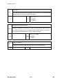
M052/M053/M054
Fax Option Type SP5200 (M381)
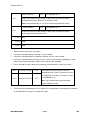
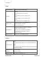
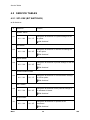
2.6 FAX OPTION TYPE SP5200 (M381)
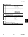
2.6.1 COMPONENT CHECK
Check the quantity and condition of the components against the following list.
No.
Description
Q’ty
1
FCU
1
2
Fax Key top
2
3
G3 Decal
1
4
Serial Number Decal
1
5
FCC Decal (NA only)
1
6
Multi-Language Decals (EU only)
1
7
Ferrite Core
8
Telephone Cord (NA only)
1
-
EMC Address Card (EU only)
1
M052/M053/M054
1 (Excluding NA)
2-18
SM
Fax Option Type SP5200 (M381)
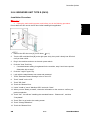
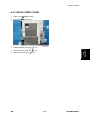
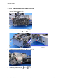
2.6.2 INSTALLATION PROCEDURE
Before installing this fax unit:
Print out all data in the printer buffer.
Turn off the main power switch and disconnect the power cord and the network cable.
Installation
x 3).
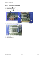
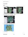
1.
Remove the FCU slot cover [A] (
2.
Switch the MBU battery jumper switch [A] to “ON” position.
SM
2-19
M052/M053/M054
Fax Option Type SP5200 (M381)
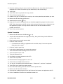
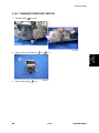
3.
Press down the place [A] on the MBU board.
4.
Install the FCU [A] into the FCU slot [B] of the machine.
Align the top edge [C] of the FCU board with the rail [D] in the FCU slot when installing
the FCU.
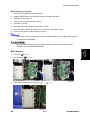
5.
Secure the FCU [A] (
6.
x 3).
Use two screws which have already been removed in step 1.
Attach the serial number decal on the area [B] of the FCU bracket and FCC decal (NA only)
on the area [C] above the serial number decal of the machine.
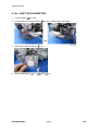
7.
Connect the telephone cord to the "LINE" jack.
M052/M053/M054
2-20
SM
For EU/AA, attach the ferrite core to the telephone cord before connecting the
telephone cord to the "LINE" jack.
For NA, use the core attached telephone cord (No.9) in the accessories of the fax unit
option.
8.
Attach an appropriate multi-language decal [A] (EU only).
9.
Replace the blank key [B] with the fax key [C].
10. Attach the decal [A] (SUPER G3) to the front door.
11. Put the power plug into the outlet and turn on the main power of the machine.
SM
2-21
M052/M053/M054
Installation
Fax Option Type SP5200 (M381)
Fax Option Type SP5200 (M381)
Make sure that the outlet is grounded.
"SRAM formatted" shows on the operation panel after you have turned the main
switch on. Turn the main switch off and on again for normal use.
12. Enter the "User Tools" mode and set date and time.
13. Do SP1000-001 in the fax SP mode and enter the serial number for the fax unit.
14. Enter the correct country code with SP1401-001 (NCU Country/ Area Code Setting).
15. Exit the SP mode, and turn the machine off and on.
M052/M053/M054
2-22
SM
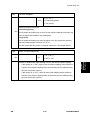
Copy Data Security Unit Type F (B829)
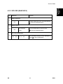
2.7 COPY DATA SECURITY UNIT TYPE F (B829)
Installation
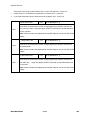
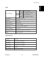
2.7.1 COMPONENTS CHECK
No.
SM
Description
Q’ty
1
ICIB-3
1
2
Flexible cable: Long (Not used)
1
3
Flexible cable: Short (Not used)
1
4
Harness with bands (Not used)
1
5
Harness (Not used)
1
6
Saddle Clamp (Not used)
1
7
Screws: M3x6
6
8
Bracket (Not used)
1
2-23
M052/M053/M054
Copy Data Security Unit Type F (B829)
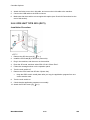
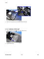
2.7.2 INSTALLATION
Unplug the main machine power cord before you do the following procedure.
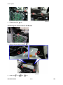
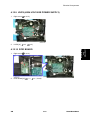
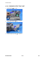
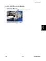
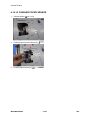
1.
Open the front door.
2.
Pull out the tray 1 [A].
3.
Remove the left cover [A] of the machine (
4.
Move the scanner I/F cable aside [A] (
5.
Move the harness guide [B] aside (
M052/M053/M054
x 3).
x 1,
x 2).
x 3).
2-24
SM
Installation
Copy Data Security Unit Type F (B829)
6.
Attach ICIB-3 [A] to CN107 [B] on the BICU (
7.
Reassemble the machine.
x 1).
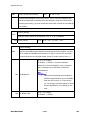
User Tool Setting
1.
Plug in the machine and turn on the main power switch.
2.
Go into the User Tools mode, and select System Settings > Administrator Tools > Copy
Data Security Option > “On”.
3.
Exit User Tools.
4.
Check the operation.
The machine will issue an SC165 error if the machine is powered on with the
ICIB-3 removed and the “Data Security for Copying“ feature set to “ON”.
The machine will issue an uncertain SC165 error if ICIB-3 is defective when the
machine is powered on and the “Data Security for Copying“ feature is set to “OFF”.
When you remove this option from the machine, first set this feature to “OFF” with
the user tool before removing this board. If you forget to do this, “Data Security for
Copying “feature cannot appear in the user tool setting. Also, SC165 will appear
every time the machine is switched on, and the machine cannot be used.
5.
SM
Make sure that the machine can recognize the option.
2-25
M052/M053/M054
Controller Options
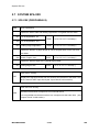
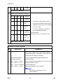
2.8 CONTROLLER OPTIONS
2.8.1 OVERVIEW
This machine has I/F card slots for optional I/F connections and SD card slot applications.
After you install an option, check that the machine can recognize it (see “Check All
Connections” at the end of this section).
SD Card Slots
Slot 1 (upper slot) [A] is used for Security Card (standard) or IPDS Unit.
If IPDS Unit is to be installed, first merge IPDS application into the Security Card with SP
mode.
Slot 2 (lower slot) [B] is used for VM card (standard) or service only (for example, updating
the firmware).
I/F Card Slot
The I/F card slot [C] is used for one of the optional I/F connections (only one can be
installed): Gigabit Ethernet, IEEE802.11a/g (Wireless LAN), or File Format Converter.
USB Slots
Both USB slots [D] are used for the Bluetooth option and a card authentication device.
M052/M053/M054
2-26
SM
Controller Options
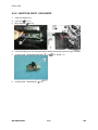
2.8.2 SD CARD APPLI MOVE
The PostScript3 application and fonts cannot be moved to another SD card. However,
Overview
The service program “SD Card Appli Move” (SP5-873) lets you copy application programs from
one SD card to another SD card.
SD slot 1 (upper ) is used to store application programs. But there are two possible applications
(Security Card (Data Overwrite Security and HDD Encryption Unit), IPDS). You cannot run
application programs from Slot 2. However you can move application programs from SD slot 2
(lower slot) to SD slot 1 (upper slot) with the following procedure.
Make sure that the target SD card has enough space.
1.
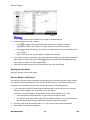
Enter SP5873 “SD Card Appli Move”.
2.
Then move the application from the SD Card in SD slot 2 (lower slot) to the SD Card in SD
slot 1 (upper slot).
3.
Do steps 1-2 again if you want to move another application program.
Exit the SP mode.
Be very careful when you do the SD Card Appli Move procedure:
The data necessary for authentication is transferred with the application program from an
SD card to another SD card. Authentication fails if you try to use the SD card after you copy
the application program from one card to another card.
Do not use the SD card if it has been used before for other purposes. Normal operation is
not guaranteed when such an SD card is used.
Keep the SD card in a safe place after you copy the application program from one card to
another card. This is done for the following reasons:
1) The SD card can be the only proof that the user is licensed to use the application
program.
2) You may need to check the SD card and its data to solve a problem in the future.
SM
2-27
M052/M053/M054
Installation
other applications can be moved onto the PostScript3 SD card.
Controller Options
Move Exec
The menu “Move Exec” (SP5-873-001) lets you copy application programs from the original SD
card to another SD card.
Do not turn ON the write protect switch of the system SD card or application SD card
on the machine. If the write protect switch is ON, a download error (e.g. Error Code 44)
occurs during a firmware upgrade or application merge.
1.
Turn the main switch off.
2.
Make sure that an SD card is in SD slot 1 (upper slot). The application program is copied to
this SD card.
3.
Insert the SD card with the application program in SD slot 2 (lower slot). The application
program is copied from this SD card.
4.
Turn the main switch on.
5.
Start the SP mode.
6.
Select SP5-873-001 "Move Exec".
7.
Follow the messages shown on the operation panel.
8.
Turn the main switch off.
9.
Remove the SD card from SD slot 2 (lower slot).
10. Turn the main switch on.
11. Check that the application programs run normally.
M052/M053/M054
2-28
SM
Controller Options
Undo Exec
“Undo Exec” (SP5-873-002) lets you copy back application programs from an SD card to the
original SD card. You can use this program when, for example, you have mistakenly copied
Do not turn ON the write protect switch of the system SD card or application SD card
on the machine. If the write protect switch is ON, a download error (e.g. Error Code 44)
occurs during a firmware upgrade or application merge.
1.
Turn the main switch off.
2.
Insert the original SD card in SD slot 2 (lower slot). The application program is copied back
into this card.
3.
Insert the SD card with the application program in SD slot 1 (upper slot). The application
program is copied back from this SD card.
4.
Turn the main switch on.
5.
Start the SP mode.
6.
Select SP5-873-002 “Undo Exec.”
7.
Follow the messages shown on the operation panel.
8.
Turn the main switch off.
9.
Remove the SD card from SD slot 2 (lower slot).
This step assumes that the application programs in the SD card are used by the
machine.
10. Turn the main switch on.
11. Check that the application programs run normally.
12. Make sure that the machine can recognize the option (see ‘Check All Connections’ at the
end of this section).
SM
2-29
M052/M053/M054
Installation
some programs by using Move Exec (SP5-873-001).
Controller Options
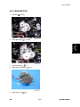
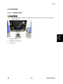
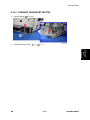
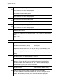
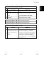
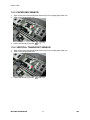
2.8.3 FILE FORMAT CONVERTER (D377)
Installation Procedure
Unplug the main machine power cord before you do the following procedure.
You can only install one of the following network interfaces or printer enhanced option at one
time: (IEEE 802.11 a/g, g (Wireless LAN), Gigabit Ethernet, or File Format Converter).
1.
Remove the I/F-slot cover [A] (
2.
Install the file format converter [A] into the I/F-slot and then fasten it with screws.
3.
Plug in and turn on the main power switch.
4.
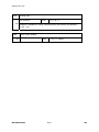
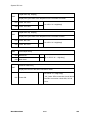
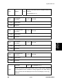
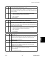
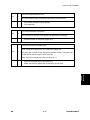
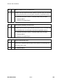
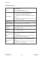
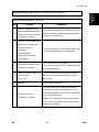
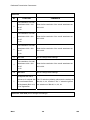
Check or set the following SP codes with the values shown below.
M052/M053/M054
x 2).
2-30
SM
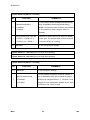
Controller Options
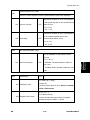
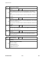
Title
Setting
SP5-836-001
Capture Function (0:Off 1:On)
"1"
SP5-836-002
Panel Setting
"0"
5.
Check the operation.
6.
Make sure that the machine can recognize the option (see ‘Check All Connections’ at the
end of this section).
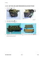
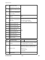
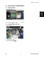
2.8.4 IEEE 802.11 A/G, G (D377: WIRELESS LAN)
Installation Procedure
Unplug the main machine power cord before you do the following procedure.
You can only install one of the following network interfaces or printer enhanced option at one
time: (IEEE 802.11 a/g, g (Wireless LAN), Gigabit Ethernet, or File Format Converter).
1.
Remove the I/F-slot cover [A] from the I/F-slot (
2.
Install the wireless LAN board [A] (Knob-screw x 2) into the I/F-slot.
3.
Make sure that the machine can recognize the option (see ‘Check All Connections’ at the
SM
2-31
x 2).
M052/M053/M054
Installation
SP No.
Controller Options
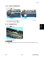
end of this section).
4.
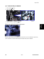
Peel off the cover from the double-sided tape on the Velcro fasteners [A], and then attach
the fasteners [A] at the scanner left cover of the machine.
5.
Attach the antennas [B] to the fasteners on the scanner left cover.
6.
Attach eight clamps as shown above.
7.
Wire the cables and clamp them (
x 8).
Make sure that the cables are not slack. Keep them wired tightly along the covers.
You may have to move the machine if the reception is not clear.
Make sure that the machine is not located near an appliance or any type of equipment that
generates strong magnetic fields.
Put the machine as close as possible to the access point.
M052/M053/M054
2-32
SM
Controller Options
UP Mode Settings for Wireless LAN
Enter the UP mode. Then do the procedure below to perform the initial interface settings for
IEEE 802.11 a/g, g. These settings take effect every time the machine is powered on.
You cannot use the wireless LAN if you use Ethernet.
1.
Press the “User Tools/Counter” key.
2.
On the touch panel, press “System Settings”.
Installation
The Network I/F (default: Ethernet) must be set for either Ethernet or wireless LAN.
3.
Select “Interface Settings”.
4.
Press “Wireless LAN”. Only the wireless LAN options show.
5.
Communication Mode. Select either “802.11 Ad hoc” or “Infrastructure”.
6.
SSID Setting. Enter the SSID setting. (The setting is case sensitive.)
7.
Channel. You need this setting when Ad Hoc Mode is selected.
Region A (mainly Europe and Asia)
Range: 1-13, 36, 40, 44 and 48 channels (default: 11)
In some countries, only the following channels are available:
Range: 1-11 channels (default: 11)
Region B (mainly North America)
SM
Range: 1-11, 36, 40, 44 and 48 channels (default: 11)
2-33
M052/M053/M054
Controller Options
8.
The allowed range for the channel settings may vary for different countries.
WEP (Encryption) Setting. The WEP (Wired Equivalent Privacy) setting is designed to
protect wireless data transmission. The same WEP key is required on the receiving side in
order to unlock encoded data. There are 64 bit and 128 bit WEP keys.
WEP:
Selects “Active” or “Inactive” (“Inactive” is default.).
Range of Allowed Settings:
64 bit: 10 characters
128 bit: 26 characters
9.
Press “Return to Default” to initialize the wireless LAN settings.
Press “Yes” to initialize the following settings:
Transmission mode
Channel
Transmission Speed
WEP
SSID
WEP Key
M052/M053/M054
2-34
SM
Controller Options
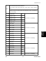
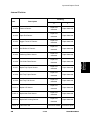
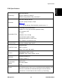
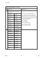
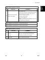
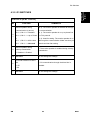
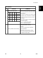
SP Mode and UP Mode Settings for IEEE 802.11 a/g, g Wireless LAN
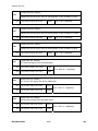
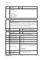
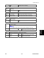
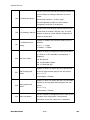
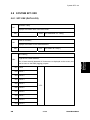
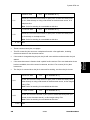
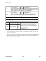
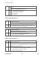
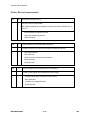
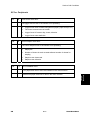
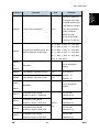
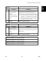
The following SP commands and UP modes can be set for IEEE 802.11 a/g, g.
Name
5840-006
Channel MAX
5840-007
Channel MIN
Function
Sets the maximum range of the channel settings for the
country.
Sets the minimum range of the channels settings
allowed for your country.
Sets the transmission speed to one of the following:
5840-008
Transmission
Auto, 54 Mbps, 48 Mbps, 36 Mbps, 24 Mbps,
Speed
18 Mbps, 12 Mbps, 9 Mbps, 6 Mbps,
11 Mbps, 5.5 Mbps, 2 Mbps, 1 Mbps (default: Auto)
5840-011
WEP Key Select
Used to select the WEP key (Default: 00).
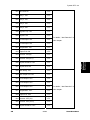
UP mode
Name
Function
SSID
Used to confirm the current SSID setting.
WEP Key
Used to confirm the current WEP key setting.
WEP Mode
SM
Used to show the maximum length of the string that
can be used for the WEP Key entry.
2-35
M052/M053/M054
Installation
SP No.
Controller Options
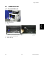
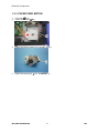
2.8.5 BLUETOOTH INTERFACE UNIT TYPE D (D566)
Installation Procedure
Unplug the main machine power cord before you do the following procedure.
1.
Install the Bluetooth [A] into the one of USB slots.
2.
Make sure that the machine can recognize the option (see ‘Check All Connections’ at the
end of this section).
M052/M053/M054
2-36
SM
Controller Options
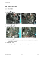
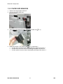
2.8.6 BROWSER UNIT TYPE E (D430)
Installation Procedure
Unplug the main machine power cord before you do the following procedure.
Installation
Do not leave the SD card in the SD slot 2 after installing this application.
1.
Remove the SD slot cover [A] for SD slots (
x 1).
2.
Turn the SD-card label face [B] to the right (rear view), then push it slowly into SD slot 2
until you hear a click.
3.
Plug in the machine and turn on the main power switch.
4.
Push the "User Tools" key.
If an administrator setting is registered for the machine, step 5 and 6 are required.
Otherwise, skip to step 7
5.
Push the "Login/ Logout" key.
6.
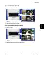
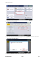
Login with the administrator user name and password.
7.
Touch "Extended Feature Settings" twice on the LCD.
8.
Touch "Install" on the LCD.
9.
Touch "SD Card".
10. Touch the "Browser" line.
11. Under "Install to" touch "Machine HDD" and touch "Next".
12. When you see "Ready to Install", check the information on the screen to confirm your
previous selection.
13. Touch "OK". You will see "Installing the extended feature... Please wait.", and then
"Completed".
14. Touch "Exit" to go back to the setting screen.
15. Touch "Change Allocation".
16. Touch the "Browser" line.
SM
2-37
M052/M053/M054
Controller Options
17. Press the hard key that you want to use for the Browser Unit. As a default, this function is
assigned to the "Other Functions" key (the bottom key of the function keys).
18. Touch "OK".
19. Touch "Exit" twice to go back to the copy screen.
20. Turn off the main power switch.
21. Install the key top for "Browser Unit" to the key slot on the operation panel where you want.
22. Remove the SD card from the SD slot 2.
23. Attach the slot cover [A] (
x 1).
24. Keep the SD card in a safe place after you install the application program from the card to
HDD. This is because that the SD card can be the only proof that the user is licensed to use
the application program. You may need to check the SD card and its data to solve a
problem in the future.
25. Turn off and on the machine.
Update Procedure
1.
Remove the SD slot cover for SD slots (
x 1).
2.
Turn the SD-card label face to the right (rear view), then push it slowly into the SD slot 2
until you hear a click.
3.
Plug in and turn on the main power switch.
4.
Push the "User Tools" key.
If an administrator setting is registered for the machine, step 5 and 6 are required.
Otherwise, skip to step 7
5.
Push the "Login/ Logout" key.
6.
Login with the administrator user name and password.
7.
Touch "Extended Feature Settings" twice on the LCD.
8.
Touch "Uninstall" on the LCD.
9.
Touch the "Browser" line
10. Confirmation message appears on the LCD.
11. Touch "Yes" to proceed.
12. Reconfirmation message appears on the LCD.
13. Touch "Yes" to uninstall the browser unit.
14. You will see "Uninstalling the extended feature... Please wait.", and then "Completed".
15. Touch "Exit" to go back to the setting screen.
16. Exit "User/Tools" setting, and then turn off the main power switch.
17. Remove the SD card from SD slot 2.
18. Overwrite the updated program in the "sdk" folder of the browser unit application with PC.
19. Do the "Installation Procedure" to install the browser unit.
M052/M053/M054
2-38
SM
Controller Options
2.8.7 GIGABIT ETHERNET BOARD TYPE A (G874)/ TYPE C (M397)
Installation Procedure
Unplug the main machine power cord before you do the following procedure.
time: (IEEE 802.11 a/g, g (Wireless LAN), Gigabit Ethernet, or File Format Converter).
1.
Remove the I/F-slot cover [A] from the I/F-slot (
2.
Attach the two caps [A] to the Ethernet (10/100 Base-T) port and the USB port as shown
x 2).
above.
3.
SM
Install the Gigabit Ethernet board [A] (Knob-screw x 2) into the I/F-slot.
2-39
M052/M053/M054
Installation
You can only install one of the following network interfaces or printer enhanced option at one
Controller Options
4.
Attach the ferrite core to the LAN cable, and connect the LAN cable to the machine.
5.
Connect the USB cable to the USB connector.
6.
Make sure that the machine can recognize this option (see ‘Check All Connections’ at the
end of this section).
2.8.8 IPDS UNIT TYPE 5210 (D571)
Installation Procedure
1.
Remove the SD slot cover [A] (
2.
Install the IPDS card [B] in SD slot 2 (lower slot).
3.
Plug in the machine, and then turn on the machine.
4.
Enter the SP mode, and then select SP5-873-001 "Move Exec".
5.
Follow the messages shown on the operation panel.
6.
Turn the main switch off.
7.
Remove the IPDS card from SD slot 2 (lower slot).
x 1).
Keep the IPDS card in a safe place after you copy the application program from one
card to another card.
8.
Turn the main switch on.
9.
Check that the application programs run normally.
10. Attach the SD slot cover [A] (
M052/M053/M054
x 1).
2-40
SM
Controller Options
2.8.9 MEMORY UNIT TYPE B 32MB (G578)
Installation Procedure
Unplug the main machine power cord before you do the following procedure.
p.4-71 "Controller Unit")
Fax unit (
2.
Push the memory unit [A] (32 MB) in the memory slot [B] until both lock levers lock the
Installation
1.
memory unit.
3.
Reassemble the machine.
2.8.10 CHECK ALL CONNECTIONS
1.
Plug in the power cord. Then turn on the main switch.
2.
Enter the printer user mode. Then print the configuration page.
User Tools > Printer Settings > List Test Print > Config. Page
All installed options are shown in the “System Reference” column.
SM
2-41
M052/M053/M054
PREVENTIVE MAINTENANCE
R E V I S I O N H I S T O RY
P a ge
Date
A d de d /U pd at e d /N ew
None
Maintenance Tables
3. PREVENTIVE MAINTENANCE
3.1 MAINTENANCE TABLES
3.1.1 USER MAINTENANCE
The customer can replace all PM items with the Maintenance Kit.
The user can maintain this machine. For more see "Printer Engine Service Mode".
After the user replaces the fusing unit in the maintenance kit, the machine automatically resets
the PM counter.
Item
Quantity
Remarks
Fusing unit
1
-
Transfer roller
1
-
Paper feed roller
5
For standard and optional tray(s)
Friction pad
5
For standard and optional tray(s)
3.1.2 SERVICE MAINTENANCE
See "Appendices" for the following information:
Preventive Maintenance Items
Other Yield Parts
SM
3-1
M052/M053/M054
Preventive
Maintenance
The operation panel shows “Replace Maintenance Kit” when the PM counter reaches 120 k.
PM Parts Settings
3.2 PM PARTS SETTINGS
3.2.1 BEFORE REMOVING THE OLD PM PARTS
1.
Enter the SP mode.
2.
Output the SMC logging data with SP5-990-004.
3.
Clear the PM counters with SP7-804.
4.
Exit the SP mode.
Item
SP
All Units
7-804-002
Fusing Unit
7-804-003
Transfer Roller
7-804-004
Paper Feed Roller
7-804-005
For the fusing unit, there is a new unit detection mechanism. It is not necessary to reset PM
counter.
3.2.2 AFTER INSTALLING THE NEW PM PARTS
1.
Turn on the main power switch.
2.
Output the SMC logging data with SP5-990-004 and check the counter values.
3.
Make sure that the PM counters for the replaced units are “0” with SP7-803. If the PM
counter for a unit was not reset, then reset that counter with SP 7-804.
3.2.3 OPERATION CHECK
Check if the sample image has been copied normally.
M052/M053/M054
3-2
SM
REPLACEMENT AND ADJUSTMENT
R E V I S I O N H I S T O RY
P a ge
Date
A d de d /U pd at e d /N ew
None
Precautions
4. REPLACEMENT AND ADJUSTMENT
4.1 PRECAUTIONS
4.1.1 GENERAL
Turn off the main power switch and unplug the machine before starting replacement.
Before turning off the main power switch, check that no mechanical component is operating.
Mechanical components may stop out of their home positions if you turn off the main power
switch while they are operating. The component may be damaged if you try to remove it when it
is not in the home position.
The AIO consists of the OPC drum, charge roller, development unit, cleaning components and
toner tank. Observe the following precautions when handling the AIO.
1.
Never touch the drum surface with bare hands. If the drum surface is dirty or if you have
accidentally touched it, wipe it with a dry cloth, or clean it with wet cotton and then wipe it
dry with a cloth.
2.
Never use alcohol to clean the drum. Alcohol will dissolve the drum surface.
3.
Store the AIO in a cool dry place.
4.
Do not expose the drum to corrosive gases (ammonia, etc.).
5.
Do not shake a used AIO, as this may cause toner to spill out.
6.
Dispose of used AIO components in accordance with local regulations.
Transfer Roller
1.
Never touch the surface of the transfer roller with bare hands.
2.
Be careful not to scratch the transfer roller, as the surface is easily damaged.
Scanner Unit
1.
Use alcohol or glass cleaner to clean the exposure and scanning glass. This will reduce the
static charge on the glass.
2.
Use a blower brush or a water-moistened cotton pad to clean the mirrors and lenses.
3.
Make sure to not bend or crease the exposure lamp’s ribbon cable.
4.
Do not disassemble the lens unit. This will cause the lens and copy image to get out of
focus.
5.
SM
Do not turn any of the LED positioning screws. This will put the LED out of position.
4-1
M052/M053/M054
Replacement
and
Adjustment
AIO
Precautions
Laser Unit
1.
Do not loosen or adjust the screws securing the LD drive board on the LD unit. This will put
the LD unit out of adjustment.
2.
Do not adjust the variable resistors on the LD unit. These are adjusted at the factory.
3.
The polygonal mirror and F-theta lens are very sensitive to dust.
4.
Do not touch the toner shield glass or the surface of the polygonal mirror with bare hands.
Fusing Unit
1.
After installing the fusing thermistor, make sure that it is in contact with the hot roller and
that the roller can rotate freely.
2.
Be careful to avoid damage to the hot roller stripper pawls and their tension springs.
3.
Do not touch the fusing lamp and rollers with bare hands.
4.
Make sure that the fusing lamp is positioned correctly and that it does not touch the inner
surface of the hot roller.
Paper Feed
1.
Do not touch the surface of the paper feed rollers.
2.
To avoid misfeeds, the side and end fences in each paper tray must be positioned correctly
so as to align with the actual paper size.
4.1.2 LITHIUM BATTERIES
Incorrect replacement of lithium battery(s) on the controller or on the fax unit poses risk
of explosion. Replace only with the same type or with an equivalent type recommended
by the manufacturer. Discard used batteries in accordance with the manufacturer’s
instructions.
4.1.3 HALOGEN-FREE CABLE
Use extreme caution while handling cables.
To comply with local regulations, halogen-free cables are used in this machine. Halogen-free
cables are environment-friendly, but no stronger than conventional cables. These cables may
be damaged in any of the following cases:
The cable is caught between hard objects such as brackets, screws, PCBs, and exterior
covers.
The cable is rubbed on a hard object such as brackets, screws, PCBs, and exterior covers.
The cable is scratched with a hard object such as brackets, screws, PCBs, exterior covers,
screwdrivers, and fingernails.
M052/M053/M054
4-2
SM
Special Tools and Lubricants
4.2 SPECIAL TOOLS AND LUBRICANTS
Part Number
Description
Q’ty
Optics Adjustment Tools (2 pcs/set)
1 set
A2929500
Test Chart – S5S (10 pcs/set)
1 set
VSSM9000
Digital Multimeter – Fluke 87
1
A2579300
Grease Barrierta – S552R
1
52039502
Silicon Grease 501
1
B6455010
SD Card
1
Replacement
and
Adjustment
A1849501
SM
4-3
M052/M053/M054
Adjusting Copy Image Area
4.3 ADJUSTING COPY IMAGE AREA
Adjust the copy image area under any of the following conditions:
1.
After clearing engine data (SP5-801-002).
2.
After replacing any of the following components:
First scanner or second scanner
Lens block
Scanner motor
Polygon mirror motor
Paper tray
4.3.1 PRINTING
Make sure that the paper is correctly loaded in each paper tray before starting the adjustment
procedures in this section.
Adjusting Registration
Use the Trimming Area Pattern (SP5-902-001 > 10) for this adjustment.
1.
Print out the test pattern with the paper fed from the regular paper tray.
2.
Print out the test pattern with the paper fed from the by-pass tray.
3.
Print out the test pattern by selecting duplex printing.
4.
Measure the distance between the leading edge of the image area and the leading edge of
the paper [A].
The diagram shows the paper on the copy tray. Note that the paper is output with
the face down.
M052/M053/M054
4-4
SM
Adjusting Copy Image Area
SP
Specification
SP1-001-001 (All Trays)
0 ± 2 mm
SP1-001-002 (By-pass)
0 ± 2 mm
SP1-001-003 (Duplex)
0 ± 4 mm
5.
Adjust the leading edge registration (SP1-001).
6.
Measure the distance between the side edge of the image area and the side edge of the
paper [B].
Specification
SP1-002-001 (1st tray)
0 ± 2 mm
SP1-002-002 (2nd tray)
0 ± 2 mm
SP1-002-005 (By-pass)
0 ± 4 mm
SP1-002-006 (Duplex)
0 ± 4 mm
7.
Adjust the side-to-side registration (SP1-002).
8.
Specify "0" (zero) in SP5-902-001 after finishing the adjustment procedure.
SM
4-5
Replacement
and
Adjustment
SP
M052/M053/M054
Adjusting Copy Image Area
Adjusting Blank Margin
Use the Trimming Area Pattern (SP5-902-001 > 10) for this adjustment.
1.
Print out the test pattern.
2.
Measure the distance between the four edges of the image area and the four edges of the
paper [A][B][C][D].
The diagram shows the paper on the copy tray. Note that the paper is output with
the face down.
3.
Adjust the blank margin (SP2-101).
SP
Specification
SP2-101-001 (Leading Edge) [A]
2 ± 1.5 mm
SP2-101-002 (Trailing Edge) [B]
2 +2.5/-1.5 mm
SP2-101-003 (Left Side) [C]
SP2-101-004 (Right Side) [D]
2 ± 1.5 mm
2 +2.5/-1.5 mm
The "Left Side" and "Right Side" comes to your left-hand side and right-hand side
respectively when you view the copied image with the leading edge upwards.
4.
Specify "0" (zero) in SP5-902-001 after finishing the adjustment procedure.
M052/M053/M054
4-6
SM
Adjusting Copy Image Area
Adjusting Main-Scan Magnification
Use the Grid Pattern (Single Dot) (SP5-902-001 > 5) for this adjustment.
SP
SP2-998-001 (Main Mag-print)
Specification
100 ± 1%
1.
Print out the test pattern.
2.
Measure the sides of squares. Each side should be 2.7-mm long.)
3.
Adjust the main-scan magnification (SP2-998-001: Main Mag-print).
4.
Specify "0" (zero) in SP5-902-001 after finishing the adjustment procedure.
4.3.2 SCANNING
Before adjusting scanning, adjust printing (
To adjust scanning, use the A4 test chart.
Replacement
and
Adjustment
Preparation:
"Printing" in this section).
Adjusting Registration
1.
Place the test chart on the exposure glass. Make sure that the test chart is aligned with the
rear and left scales on the exposure glass.
2.
Make a copy.
3.
Measure the distance between the leading edge of the image area and the leading edge of
the paper [A].
The diagram shows the paper on the copy tray. Note that the paper is output with
the face down.
SM
4-7
M052/M053/M054
Adjusting Copy Image Area
4.
Adjust the leading-edge scan registration. (SP4-010-001).
SP
Specification
SP4-010-001 (Leading Edge
0 ± 2 mm
Registration Adj)
5.
Measure the distance between the side edge of the image area and the side edge of the
paper [B].
6.
Adjust the side-to-side registration (SP4-011-001).
SP
Specification
SP4-011-001 (Main Scan Reg)
0 ± 2.5 mm
Adjusting Magnification
1.
Place the test chart on the exposure glass. Make sure the test chart is aligned with the rear
and left scales on the exposure glass.
2.
Make a copy.
3.
Compare the copy with the original.
4.
Adjust the main-scan and sub-scan magnifications. The original image [A] is magnified in
the sub-scan direction [B] when you specify a larger value.
M052/M053/M054
4-8
SM
Adjusting Copy Image Area
The diagrams show the paper on the copy tray. Note that the paper is output with the
face down.
SP
SP4-008-001 (Sub Scan
Magnification Adj)
Specification
± 1.0%
4.3.3 DF IMAGE ADJUSTMENT
Perform the adjustment procedure in this section only when the ARDF is installed on
Replacement
and
Adjustment
the copier.
1.
Make a temporary test chart as shown in the above diagram. Use the “A4/8.5 x 11" paper to
make it.
2.
Place the temporary test chart on the ARDF.
3.
Make a copy.
4.
Measure the distance between the side edge of the image area and the side edge of the
paper [A].
(The diagram shows the paper on the copy tray. Note that the paper is output with the face
down.)
5.
SM
Adjust the side-to-side registration (S to S/Front Regist: SP6-006-001, S to S/Rear Regist:
4-9
M052/M053/M054
Adjusting Copy Image Area
SP6-006-002). The image area moves to the rear side of the copier when you specify a
larger value.
6.
Measure the distance between the leading of the image area and the leading edge of the
paper [B].
7.
Adjust the leading edge registration (Leading Regist: SP6-006-003). The image area
moves to the right side of the copier when you specify a larger value.
8.
Measure the distance between the trailing edge of the image area and the trailing edge of
the paper [C].
9.
Adjust the erased area on the trailing edge (Trailing Erase: SP6-006-007).
10. Compare the copy with the original.
11. Adjust the sub-scan magnification (SP6-017-001). The specification is ±1.0%.
M052/M053/M054
4-10
SM
Exterior Covers
4.4 EXTERIOR COVERS
4.4.1 LEFT COVER
Open the frond door.
2.
Pull out the tray 1 [A].
3.
Left cover [A] (
Replacement
and
Adjustment
1.
SM
x 3)
4-11
M052/M053/M054
Exterior Covers
4.4.2 RIGHT COVER
1.
Open the frond door.
2.
Pull out the tray 1 [A].
3.
Right cover [A] (
M052/M053/M054
x 3)
4-12
SM
Exterior Covers
4.4.3 REAR LOWER COVER
1.
Right cover (
2.
Left cover (
3.
Rear left upper cover [A] (
x 2)
4.
Rear left lower cover [B] (
x 2)
5.
Rear lower cover [C] (
SM
Right Cover)
Replacement
and
Adjustment
Left Cover)
x 2)
4-13
M052/M053/M054
Exterior Covers
4.4.4 FRONT DOOR
1.
Press the front cover release button [A].
2.
Open the front door [B].
3.
Pull out the tray.
4.
Right cover (
5.
Release the spring [A].
6.
Release the right arm [B] of the front cover.
7.
Front door [C]
M052/M053/M054
Right Cover)
4-14
SM
Exterior Covers
4.4.5 DUPLEX UNIT
Open the duplex unit [A].
2.
Release the spring [B] and two harnesses of the duplex unit.
3.
Duplex unit [A]
Replacement
and
Adjustment
1.
SM
4-15
M052/M053/M054
Exterior Covers
4.4.6 OPERATION PANEL UNIT
Operation Panel Unit
Operation Panel Frame Cover Removal
For M052 model
x 2)
1.
Operation panel lower cover [A] (
2.
Remove the operation panel upper cover.
For M053/ M054 model
1.
Internal finisher (For M054 model) (
2.
Operation panel frame upper cover [A] (
3.
Operation panel arm upper cover [B] (
M052/M053/M054
p.4-104)
x 2)
x 2)
4-16
SM
Exterior Covers
4.
Operation panel frame lower cover [A] (
x 2)
Replacement
and
Adjustment
Operation Panel Unit Removal
5.
Disconnect the harness and USB cable [A].
6.
Remove the three screws.
SM
4-17
M052/M053/M054
Exterior Covers
7.
Operation panel unit [A] (
x 2)
Key Tops
1.
Operation panel unit (
2.
Operation panel arm holder [A] (
x 2)
3.
Operation panel rear cover [A] (
x 7)
M052/M053/M054
p.4-16)
4-18
SM
Exterior Covers
x 5,
Operation panel bracket [A] (
5.
Release the Key: main board [A] (
6.
Key tops [A] (hooks)
x 3)
Replacement
and
Adjustment
4.
SM
x 5)
4-19
M052/M053/M054
Exterior Covers
4.4.7 TOUCH PANEL POSITION ADJUSTMENT
It is necessary to calibrate the touch panel at the following times:
When you replace the operation panel.
When you replace the controller board.
When the touch panel detection function does not operate correctly
Do not use items [2] to [9] on the Self-Diagnostic Menu. These items are for design use only.
1.
Press
, press "1" "9" "9" "3" key, press "Clear/Stop" key 5 times to open the
Self-Diagnostics menu.
2.
On the touch screen press “Touch Screen Adjust” (or press "1" key).
3.
Use a pointed (not sharp) tool to press the upper left mark
4.
Press the lower right mark when “ ” shows.
5.
Press [#] OK on the screen (or press
6.
Touch [#] Exit on the screen to close the Self-Diagnostic menu. Save the calibration
.
) when you are finished.
settings.
M052/M053/M054
4-20
SM
Exterior Covers
4.4.8 OUTPUT TRAY (M052/M053 MODELS ONLY)
1.
Left cover (
2.
Right cover (
3.
Only for M053, remove the 1 bin tray unit (
4.
Inner left cover [A]
5.
Output tray [A] (
SM
p.4-11)
p.4-12)
Replacement
and
Adjustment
p.4-126).
x 4)
4-21
M052/M053/M054
Scanner Unit
4.5 SCANNER UNIT
4.5.1 SCANNER FRONT COVER
1.
Open the ARDF.
2.
Operation panel unit (
3.
Release the hook [A] under the scanner unit.
4.
Scanner front cover [B] (
M052/M053/M054
p.4-16)
x 1, hook x 1, boss x 2)
4-22
SM
Scanner Unit
4.5.2 SCANNER RIGHT AND LEFT COVERS
Scanner Right Cover
Scanner front cover (
p.4-22)
2.
Scanner right cover [A] (
x 2)
Replacement
and
Adjustment
1.
Scanner Left Cover
1.
Scanner front cover (
p.4-22)
2.
Scanner left cover (
x 2)
SM
4-23
M052/M053/M054
Scanner Unit
4.5.3 SCANNER REAR COVER
1.
Scanner front cover (
2.
Scanner right and left covers (
3.
Scanner rear cover [A] (
M052/M053/M054
p.4-22)
p.4-23)
x 3)
4-24
SM
Scanner Unit
4.5.4 EXPOSURE GLASS
1.
Open the ARDF.
2.
Glass cover [A] (
3.
DF exposure glass [B]
4.
Rear scale [A] (
5.
Exposure glass [B] with the left scale
Replacement
and
Adjustment
x 2)
x 3)
When reassembling the ARDF exposure glass
Position the blue marker [A] at the rear-right corner when you reattach the ARDF exposure
glass.
SM
4-25
M052/M053/M054
Scanner Unit
4.5.5 LED BOARD
Do not touch a new LED board directly by hands. Oily spots on the LED board will
cause poor scanning quality.
p.4-87)
1.
ARDF (
2.
Scanner top rear cover (
3.
Exposure glass (
4.
Move the 1st scanner carriage [A] to the right side by rotating the scanner motor [B]
x 1)
p.4-25)
clockwise in view of the rear.
M052/M053/M054
4-26
SM
Scanner Unit
Remove the screw at the front side of the 1st scanner carriage.
6.
Move back the 1st scanner carriage [A] to the left side by rotating the scanner motor
Replacement
and
Adjustment
5.
counterclockwise in view of the rear.
7.
SM
Remove the screw at the rear side of the 1st scanner carriage.
4-27
M052/M053/M054
Scanner Unit
8.
Move the 1st scanner carriage [A] to the cutout position [B] by rotating the scanner motor
clockwise.
9.
LED board [B] (
M052/M053/M054
x 2,
x 1)
4-28
SM
Scanner Unit
4.5.6 SCANNER MOTOR
1.
Scanner rear cover (
p.4-24)
2.
Disconnect the harness [A] and remove the spring [B]
3.
Scanner motor bracket [C] (
4.
Scanner motor [A] (
Replacement
and
Adjustment
x 2, timing belt x 1)
x 2)
Do the scanner image adjustment after replacing the scanner motor (see "Image
Adjustment").
SM
4-29
M052/M053/M054
Scanner Unit
4.5.7 SENSOR BOARD UNIT (SBU)
1.
Scanner top rear cover (
2.
Exposure glass (
3.
Bracket [A] (
4.
Sensor board unit [A] (
p.4-26 "LED Board")
p.4-25)
x 5)
x 4,
x 2)
When reassembling
Adjust the following SP modes after you replace the sensor board unit:
SP4–008 (Sub Scan Magnification Adj): See "Image Adjustment: Scanning"(
SP4–010 (Leading Edge Registration Adj): See "Image Adjustment: Scanning"(
SP4–011 (Main Scan Reg): See "Image Adjustment: Scanning"(
SP4–688 (DF: Density Adjustment): Use this to adjust the density level if the ID of outputs
p.4-7).
p.4-7)).
p.4-7).
made in the DF and Platen mode is different.
M052/M053/M054
4-30
SM
Scanner Unit
4.5.8 LED DRIVE BOARD
Scanner rear cover (
p.4-24)
2.
Release the harness [A] from three clamps, and then take it aside.
3.
LED drive board bracket [A] (
4.
LED drive board [A] (
Replacement
and
Adjustment
1.
SM
x 2,
x 2)
x 4)
4-31
M052/M053/M054
Scanner Unit
4.5.9 SCANNER HP SENSOR
1.
ARDF (
p.4-87)
2.
Scanner top rear cover (
3.
Move the 1st scanner carriage [A] to the right side by rotating the scanner motor [B].
4.
Remove the mylar [A].
5.
Scanner HP sensor [A] (
M052/M053/M054
p.4-26 "LED Board")
x 1, hooks).
4-32
SM
Scanner Unit
4.5.10 COVER SENSOR
ARDF (
p.4-87)
2.
Scanner top rear cover (
3.
Cover sensor [A] (
p.4-26 "LED Board")
Replacement
and
Adjustment
1.
SM
x 1, hooks)
4-33
M052/M053/M054
Scanner Unit
4.5.11 FRONT SCANNER WIRE
1.
Exposure glass (
p.4-25)
2.
ARDF (
3.
Scanner top rear cover (
p.4-26 "LED Board")
4.
Scanner front frame [A] (
x 5)
5.
Front scanner wire holder [A] (
6.
Front scanner wire bracket [B] (
7.
Front scanner wire, white clip [C] and scanner drive pulley [D] (
p.4-87)
M052/M053/M054
x 1)
x 1)
4-34
x 1)
SM
Scanner Unit
1.
Position the center ball [A] in the middle of the forked holder.
2.
Pass the right end (with the ball) [B] through the square hole. Pass the left end (with the
ring) [C] through the notch.
3.
Wind the right end counterclockwise (shown from the machine's front). Wind the left end
clockwise.
The two blue marks [D] come together when you have done this. Stick the wire to
the pulley with tape. This lets you easily handle the assembly at the time of
installation.
SM
4-35
M052/M053/M054
Replacement
and
Adjustment
Reinstalling the Front Scanner Wire
Scanner Unit
4.
Install the drive pulley on the shaft [A].
5.
Do not secure the pulley to the shaft at this time.
Insert the left end into the slit [B]. The end should go via the rear track of the left pulley [C]
and the rear track of the movable pulley [D].
6.
Hook the right end onto the front scanner wire bracket [A]. The end should go via the front
track of the right pulley [B] and the front track of the movable pulley [C].
M052/M053/M054
4-36
SM
Replacement
and
Adjustment
Scanner Unit
7.
Remove the tape from the drive pulley.
8.
Insert a scanner-positioning pin [A] through the 2nd carriage hole [B] and the left holes [C]
in the front rail. Insert another scanner positioning pin [D] through the 1st carriage hole [E]
and the right holes in the front rail [F].
9.
Insert two more scanner positioning pins through the holes in the rear rail.
10. Install the white clip [G] and drive pulley to the shaft [H] (
x 1).
11. Screw the scanner wire bracket to the front rail [I].
12. Screw the scanner wire holder [J].
13. Pull out the positioning pins.
Make sure the 1st and 2nd carriages move smoothly after you remove the
positioning pins. Do steps 8 through 13 again if they do not.
SM
4-37
M052/M053/M054
Scanner Unit
4.5.12 REAR SCANNER WIRE
1.
Exposure glass (
p.4-25)
2.
ARDF (
1.
Scanner top rear cover (
2.
Main power switch bracket [A] (
3.
Scanner rear frame [A] (
4.
White pulley [A] (
5.
Follow steps 5 through 7 in the "Front Scanner Wire" Section. You can remove the rear
p.4-87)
p.4-26 "LED Board")
x 2)
x 5)
x 1)
scanner wire with the same manner for replacing the front scanner wire.
M052/M053/M054
4-38
SM
Scanner Unit
Reinstalling the Rear Scanner Wire
1.
Position the center ball [A] in the middle of the forked holder.
2.
Pass the left end (with the ball) [B] through the drive pulley notch. Pass the right end (with
the ring) [C] through the drive pulley hole.
Wind the left end [B] clockwise (shown from the machine's front). Wind the right end [C]
counterclockwise.
The two blue marks [D] come together when you do this. Attach the wire to the
pulley with tape. This lets you easily handle the assembly at the time of installation.
4.
Install the drive pulley on the shaft.
5.
Do not attach the pulley on the shaft with the screw at this time.
Install the wire.
The winding of the wire on the three pulleys at the rear of the scanner should be
the same as the winding on the three pulleys at the front. This must show as a
mirror image.
Example: At the front of the machine, the side of the drive pulley with the three windings
must face the front of the machine. At the rear of the machine, it must face the rear.
6.
SM
Do steps 8 through 13 again in the "Reinstalling the Front Scanner Wire" Section.
4-39
M052/M053/M054
Replacement
and
Adjustment
3.
Laser Optics
4.6 LASER OPTICS
Turn off the main power switch and unplug the machine before beginning any of the
procedures in this section. Laser beams can cause serious eye injury.
4.6.1 CAUTION DECAL LOCATIONS
Caution decals are attached as shown below.
Be sure to turn off the main power switch and disconnect the power plug from the
power outlet before beginning any disassembly or adjustment of the laser unit. This
machine uses a class IIIb laser beam with a wavelength of 785 nm and an output of 6.2
mW. The laser can cause serious eye injury.
M052/M053/M054
4-40
SM
Laser Optics
Laser Exposure
LD Safety Switch
A safety switch turns off when the front cover or the rear door is opened. As a result, the relay
on the PSU cuts off the power supply (+5V) to the LD board. (The electric circuits go through the
engine board) This system prevents unexpected laser emission, and ensures user safety and
technician safety.
4.6.3 LASER UNIT
The removal procedure of the "Preparation before Removing the Laser Unit" differs depending
on the models. Refer to the target model under the "Preparation before Removing the Laser
Unit".
Preparation before Removing the Laser Unit
For M052 models
1.
Output tray (
p.4-21)
For M053 models
1.
1 bin tray unit (
2.
Output tray (
p.4-126).
p.4-21)
For M054 model
1.
SM
Internal finisher (
p.4-104)
4-41
M052/M053/M054
Replacement
and
Adjustment
4.6.2 SAFETY SWITCHES FOR LASER UNIT
Laser Optics
2.
Finisher stay [A] (
x 4)
Removing the Laser Unit for All Models
1.
Remove the two ground cables (
2.
Laser unit (
M052/M053/M054
x 4,
x 2,
x 1).
x 2)
4-42
SM
Laser Optics
4.6.4 POLYGON MOTOR
1.
Laser unit (
2.
Remove the tape [A] on the laser unit cover.
Keep this tape. This tape is necessary when reassembling the laser unit.
3.
Laser unit cover [B] (
4.
Polygon motor [A] (
SM
x 1,
x 4,
x 2, ground cable x 1)
Replacement
and
Adjustment
p.4-41)
x 1)
4-43
M052/M053/M054
Laser Optics
4.6.5 LASER SYNCHRONIZATION DETECTOR
1.
Laser unit (
2.
Laser synchronization detector [A] (
M052/M053/M054
p.4-41)
x 1)
4-44
SM
Paper Transfer
4.7 PAPER TRANSFER
4.7.1 TRANSFER ROLLER
Open the front door.
2.
AIO [A]
3.
Pull the transfer roller holder [A].
4.
Transfer roller [B]
Replacement
and
Adjustment
1.
SM
4-45
M052/M053/M054
Drive Section
4.8 DRIVE SECTION
4.8.1 GEARBOX
1.
Left cover (
2.
BICU bracket (
3.
AIO fan [A] (
4.
AIO fan duct [B] (
5.
Gearbox cover [A] (
p.4-11)
p.4-81)
x 2,
x 1)
x 2)
x 3)
Hold the gearbox cover [A] while removing it. Otherwise, the spring inside the gearbox
cover suddenly comes off.
6.
Gearbox [B] (
x 3)
Hold the gearbox [B] while removing it. Otherwise, the spring inside the gearbox
suddenly comes off.
M052/M053/M054
4-46
SM
Drive Section
4.8.2 MAIN MOTOR
1.
Gearbox (
p.4-46)
2.
Drive gears [A] (
3.
Ground plate [A] (
4.
Main motor bracket [B] (
5.
Main motor [A] (
Replacement
and
Adjustment
x 1 each)
SM
x 1)
x 4)
x 1)
4-47
M052/M053/M054
Drive Section
4.8.3 DUPLEX MOTOR
1.
BICU bracket (
2.
Duplex motor bracket (
3.
Duplex motor [A] (
M052/M053/M054
p.4-81)
x 3,
x 1)
x 2, timing belt x 1)
4-48
SM
Drive Section
4.8.4 BY-PASS FEED CLUTCH
1.
Left cover (
p.4-11)
2.
By-pass feed clutch [A] (
x 1,
x 1,
x 1)
x 1,
x 1,
x 1)
1.
Left cover (
1.
By-pass feed clutch [A] (
SM
Replacement
and
Adjustment
4.8.5 RELAY CLUTCH
p.4-11)
4-49
M052/M053/M054
Drive Section
4.8.6 PAPER FEED CLUTCH
1.
BICU bracket (
p.4-81)
2.
Clutch holder [A] (
3.
Paper feed clutch [B] (
x 1)
x 1)
4.8.7 REGISTRATION CLUTCH
1.
BICU bracket (
2.
Registration clutch [A] (
M052/M053/M054
p.4-81)
x 1,
x 1)
4-50
SM
Paper Feed
4.9 PAPER FEED
4.9.1 PAPER FEED ROLLER
Pull out the tray 1 [A].
2.
Slide the paper feed roller shaft to the left.
3.
Paper feed roller [B]
Replacement
and
Adjustment
1.
SM
4-51
M052/M053/M054
Paper Feed
4.9.2 FRICTION PAD
1.
Pull out the tray 1.
2.
Friction pad [A] (hooks, spring x 1)
When reassembling the friction pad
When reinstalling the friction pad, make sure that the mylar [A] is placed outside the friction pad.
M052/M053/M054
4-52
SM
Paper Feed
4.9.3 PAPER END SENSOR
Pull out the tray 1.
2.
Filler [A] for the paper end sensor
3.
Paper end sensor [B] (hooks,
x 1)
Replacement
and
Adjustment
1.
4.9.4 REMAINING PAPER SENSORS
1.
Pull out the tray 1.
2.
Filler [A] for the remaining paper sensors
3.
Remaining paper sensors [B] (hooks,
SM
x 1 each)
4-53
M052/M053/M054
Paper Feed
4.9.5 REGISTRATION SENSOR
1.
AIO (
p.4-45 "Transfer Roller")
1.
Registration roller guide cover [A] (hooks)
2.
Registration sensor [B] (
x 1)
4.9.6 BY-PASS PAPER SENSOR
1.
Left cover (
2.
Close the front door [A].
3.
By-pass feed clutch [B] (
4.
By-pass paper sensor [C] (hooks,
M052/M053/M054
p.4-11)
x 1)
x 1)
4-54
SM
Paper Feed
4.9.7 DUPLEX RELAY SENSOR
1.
BICU bracket (
p.4-81)
2.
Main motor (
3.
Duplex relay sensor [A] (hooks,
p.4-47)
x 1)
Replacement
and
Adjustment
When reassembling the duplex relay sensor
Keep the duplex relay sensor filler [A] downward with a thin tool when installing the duplex relay
sensor. Otherwise, the sensor filler interrupts the duplex relay sensor installation.
SM
4-55
M052/M053/M054
Paper Feed
4.9.8 JUNCTION GATE 1 SOLENOID
1.
Open the duplex unit.
2.
Left cover (
3.
BICU bracket (
4.
Lift up the filler [A] of the fusing exit sensor when removing the junction gate 1 bracket.
5.
Junction gate 1 solenoid bracket [B] (
6.
Junction gate 1 solenoid [A] (
M052/M053/M054
p.4-11)
p.4-81)
x 2,
x 2, spring x 1)
x 2)
4-56
SM
Paper Feed
4.9.9 JUNCTION GATE 2 SOLENOID
Left cover (
p.4-11)
2.
Junction gate 2 solenoid bracket [A] (
3.
Junction gate 2 solenoid [A]
x 1,
x 2)
Replacement
and
Adjustment
1.
SM
4-57
M052/M053/M054
Paper Feed
4.9.10 FUSING EXIT SENSOR (M053 MODEL ONLY)
1.
Left cover (
p.4-11)
2.
BICU bracket (
3.
Junction gate 1 solenoid bracket (
4.
Fusing exit sensor [A]
p.4-81)
p.4-56 "Junction Gate 1 Solenoid")
4.9.11 PAPER OVERFLOW SENSOR (M052/M053 MODELS ONLY)
1.
Output tray (
2.
Paper overflow sensor [A] (hooks,
M052/M053/M054
p.4-21)
x 1)
4-58
SM
Fusing
4.10 FUSING
4.10.1 FUSING UNIT
Before handling the fusing unit, make sure that the unit is cool enough. The fusing unit
1.
Open the duplex unit.
2.
Release the lock levers.
3.
Fusing unit.
SM
Replacement
and
Adjustment
can be very hot.
4-59
M052/M053/M054
Fusing
4.10.2 HOT ROLLER AND PRESSURE ROLLER SECTIONS
1.
Fusing unit (
p.4-59)
2.
Fusing left cover [A] (
3.
Fusing right cover [B] (
4.
Separate the fusing unit [A] into two sections (
x 1)
x 1)
x 4): the hot roller section [B] and the
pressure roller section [C]
M052/M053/M054
4-60
SM
Fusing
4.10.3 FUSING LAMP
1.
Fusing unit (
2.
Fusing left and right covers (
3.
Lamp left stay [A] (
4.
Remove the screw [B] on the left terminal of the fusing unit.
5.
Lamp right stay [C] (
6.
Remove the screw [D] on the right terminal of the fusing unit.
7.
Fusing lamp [A]
SM
p.4-59)
p.4-60 "Hot Roller and Pressure Roller Sections")
Replacement
and
Adjustment
x 1)
x 1)
4-61
M052/M053/M054
Fusing
4.10.4 HOT ROLLER
Do not touch the fusing lamp and rollers with your bare hands.
p.4-60 "Hot Roller and Pressure Roller Sections")
1.
Hot roller section (
2.
Fusing lamp (
3.
Hot roller gear [A] (c-ring x 1)
4.
Hot roller left stay [B] (
5.
Hot roller right stay [C] (
6.
Remove the c-ring [D].
7.
Hot roller [A] (bearing x 2, insulator x 2)
p.4-61)
x 1)
x 1)
Slowly pull out the hot roller from the hot roller section not to damage the hot roller due
to the five stripper pawls on the hot roller section.
M052/M053/M054
4-62
SM
Fusing
4.10.5 FUSING THERMISTOR
1.
Fusing unit (
p.4-59)
2.
Fusing drawer connector [A] (
3.
Fusing thermistor [B] (
x 1,
x 1)
x 1)
1.
Hot roller (
2.
Thermostats [A] (
Replacement
and
Adjustment
4.10.6 THERMOSTATS
p.4-62)
x 2)
Do not recycle thermostats that are already opened. Safety is not guaranteed if you do
this.
SM
4-63
M052/M053/M054
Fusing
4.10.7 PRESSURE ROLLER
1.
Pressure roller section (
p.4-60 "Hot Roller and Pressure Roller Sections")
2.
Fusing entrance guide [A] (
3.
Pressure roller [A] (bearing x 2)
x 3)
4.10.8 FUSING CLEANING ROLLER
1.
Pressure roller section (
2.
Pressure roller (
3.
Fusing cleaning roller [A]
M052/M053/M054
p.4-60)
p.4-64r)
4-64
SM
Duplex Unit
4.11 DUPLEX UNIT
4.11.1 DUPLEX UNIT
Open the duplex unit [A].
2.
Release the spring [B] and two harnesses of the duplex unit.
3.
Duplex unit [A]
Replacement
and
Adjustment
1.
SM
4-65
M052/M053/M054
Duplex Unit
4.11.2 DUPLEX INVERTER MOTOR
1.
Duplex unit (
2.
Duplex left cover [A] (
3.
Gear [A] (
4.
Duplex inverter motor bracket [B] (
5.
p.4-65)
x 2)
x 1, timing belt x 2)
x 4,
x 1)
Two of these screws secure the ground cables (blue and gray cords).
Duplex inverter motor [A] (
M052/M053/M054
x 2)
4-66
SM
Duplex Unit
4.11.3 DUPLEX EXHAUST FAN
1.
Duplex unit (
p.4-65)
2.
Duplex left cover (
3.
Duplex right cover [A] (
4.
Remove screw [A] on the left of the duplex unit and screw [B] on the right of the duplex unit.
5.
Release the two bosses [A] of the duplex rear cover [B].
p.4-66 "Duplex Inverter Motor")
Replacement
and
Adjustment
x 2)
SM
4-67
M052/M053/M054
Duplex Unit
6.
Release the boss [A] on the left side.
7.
Slowly turn over the duplex rear cover [A], and then remove it (
8.
Duplex exhaust fan [A] (
M052/M053/M054
x 2,
x 1).
x 1).
4-68
SM
Duplex Unit
4.11.4 DUPLEX INVERTER SENSOR
1.
Duplex unit (
p.4-65)
2.
Duplex rear cover (
1.
Sensor holder [A] (
2.
Ground plate [A] (
3.
Duplex inverter sensor [B] (hooks,
p.4-67 "Duplex Exhaust Fan")
Replacement
and
Adjustment
x 1)
SM
x 1)
x 1)
4-69
M052/M053/M054
Duplex Unit
4.11.5 DUPLEX ENTRANCE SENSOR
1.
Duplex unit (
2.
Duplex rear cover (
3.
Duplex entrance sensor bracket [A] (
x 1)
4.
Duplex entrance sensor [A] (hooks,
x 1)
M052/M053/M054
p.4-65)
p.4-67 "Duplex Exhaust Fan")
4-70
SM
Electrical Components
4.12 ELECTRICAL COMPONENTS
4.12.1 CONTROLLER UNIT
SM
Controller unit [A] (
x 4)
Replacement
and
Adjustment
1.
4-71
M052/M053/M054
Electrical Components
4.12.2 HDD UNIT
1.
Controller unit (
2.
Fax slot bracket [A] (
3.
HDD unit bracket [A] (
4.
HDD unit [A] (
M052/M053/M054
p.4-71)
x 4,
x 2) or fax unit [B] if it has been installed (
x 2)
x 4)
x 2)
4-72
SM
Electrical Components
4.12.3 HDD CONTROL BOARD
1.
Controller unit (
p.4-71)
2.
HDD unit bracket (
3.
HDD control board (
p.4-72 "HDD Unit")
x 2,
x 2)
1.
Controller unit (
2.
HDD unit bracket (
3.
NVRAM [A]
SM
Replacement
and
Adjustment
4.12.4 NVRAM
p.4-71)
p.4-72 "HDD Unit")
4-73
M052/M053/M054
Electrical Components
When reinstalling a new NVRAM
Make sure that you have the SMC report (factory settings). This report comes with the machine.
1.
Print the SMC data (”ALL”) using SP5-990-001.
2.
Turn off the main switch.
3.
Remove the VM card from SD card Slot 2 (Lower).
4.
Insert a blank SD card into Slot 2 (Lower), and then turn on the main power switch.
5.
Upload the NVRAM data to the blank SD card using SP5-824-001 (NVRAM Data Upload).
6.
Turn off the main power switch, and then unplug the AC power cord.
7.
Remove the SD Card containing the NVRAM data from Slot 2 (Lower).
8.
Replace the NVRAM on the Controller Board with a new one.
9.
Plug in the AC power cord, and then turn on the main power switch
When you do this, SC995-02 (Defective NVRAM) will be displayed. However, do
not turn off the main power switch. Continue this procedure.
10. Re-insert the SD card that you removed in Step 7 back into Slot 2 (Lower)
11. Download the old NVRAM data from the SD card onto the new NVRAMs using
SP5-825-001 (NVRAM Data Download).
This will take about 2 or 3 minutes.
12. Turn off the main power switch, and then remove the SD card from Slot 2 (Lower).
13. Insert the VM card into Slot 2 (Lower).
14. Turn on the main power switch.
15. Print the SMC data (”ALL”) using SP5-990-001, and make sure that it matches the SMC
data you printed out in Step 1 above (except for the value of the total counter).
M052/M053/M054
4-74
SM
Electrical Components
The value of the total counter is reset to “0” when the NVRAM is replaced.
Do all of the following if SP5-824-001 (NVRAM Data Upload) and SP5-825-001
(NVRAM Data Download) cannot be performed for some reason:
1. Replace the NVRAM and Security SD card together as a set with new ones.
2. Manually enter all data on the SMC report (factory settings).
3. Install the new Security SD card functions (Data overwrite and HDD encryption)
Replacement
and
Adjustment
again. See RTB #RGene039 for the procedure.
SM
4-75
M052/M053/M054
Electrical Components
4.12.5 EEPROMS
1.
Left cover (
p.4-11)
2.
EEPROMs [A]
When reinstalling a new EEPROM
1.
Make sure that you have the SMC report (factory settings). This report comes with the
M052/M053/M054
4-76
SM
Electrical Components
machine.
2.
Output the SMC data (SP5-990-001) if possible.
3.
Turn the main switch off.
4.
Install an SD card into SD card slot 2 (lower slot). Then turn the main power on.
5.
Copy the EEPROM data to an SD card (SP5-824-001) if possible.
6.
Turn off the main switch. Then unplug the power cord.
7.
Replace the EEPROM on the BICU and reassemble the machine.
8.
Install a new EEPROM (labeled FRAM0) in the upper slot [A] with the half-disk mark [B]
facing the upward and EEPROM (labeled FRAM1) in the lower slot [C] with the half-disk
mark [B] facing the downward.
Make sure that a FRAM0 EEPROM and FRAM1 EEPROM are installed in the
correct position.
9.
Plug in the power cord. Then turn the main switch on.
copied them to the SD card.
11. Turn the main switch off. Then remove the SD card from SD card slot 2 (lower slot).
12. Turn the main switch on.
13. Specify the SP and UP mode settings.
If NVRAM Data Upload and Download cannot be done for BICU EEPROMs:
Do all of the following procedure if SP5-824-001 (NVRAM Data Upload) and SP5-825-001
(NVRAM Data Download) cannot be performed for some reason:
1.
Manually enter all data on the SMC report (factory settings).
4.12.6 DIMM RAM
1.
Controller unit (
2.
Release the locks [A], and then remove the DIMM RAM(s) [B]
SM
p.4-71)
4-77
M052/M053/M054
Replacement
and
Adjustment
10. Copy the data from the SD card to the EEPROM (SP5-825-001) if you have successfully
Electrical Components
4.12.7 CONTROLLER BOARD
1.
Controller unit (
p.4-71)
2.
DIMM RAMs (
3.
HDD unit bracket (
4.
NVRAM (
5.
Controller board with rails [A] (
6.
Two Rails [A]
7.
Controller board [B]
p.4-77)
p.4-72 "HDD Unit")
p.4-73)
M052/M053/M054
x 3)
4-78
SM
Electrical Components
When installing a new controller board
1.
Remove the NVRAM from the old controller board.
2.
Install the NVRAM on a new controller board after you replace the controller board.
3.
Reassemble the machine.
4.
Turn on the main power of the machine
Make sure you print out the SMC reports (“SP Mode Data” and “Logging Data”) before
you replace the NVRAM.
Keep NVRAM away from any objects that can cause static electricity. Static electricity
can damage NVRAM data.
Make sure the NVRAM is correctly installed on the controller board.
Replacement
and
Adjustment
SM
4-79
M052/M053/M054
Electrical Components
4.12.8 BICU
BICU
1.
Left cover (
2.
Take aside the scanner I/F cable [A] (
3.
Take aside the harness guide [B] (
4.
BICU [A] (
5.
EEPROMs [A]
M052/M053/M054
p.4-11)
x All,
x all,
x 1,
x 2).
x 3).
x 6)
4-80
SM
Electrical Components
When installing a new BICU
1.
Remove the EEPROM from the old BICU.
2.
Install the EEPROM on the new BICU after you replace the BICU.
3.
Reassemble the machine.
4.
Turn on the main power of the machine.
5.
"SC995-01" occurs.
6.
Enter the SP mode, and then select SP5-811-004.
7.
Enter the serial number with SP5-811-004, and then exit the SP mode.
8.
Turn the main power of the machine off and on.
Make sure you print out the SMC reports (“SP Mode Data” and “Logging Data”) before
you replace the EEPROM.
Keep an EEPROM away from any objects that can cause static electricity. Static
Replacement
and
Adjustment
electricity can damage EEPROM data.
BICU Bracket
1.
Left cover (
2.
Controller unit (
3.
Take aside the scanner I/F cable [A] (
SM
p.4-11)
p.4-71)
x 1,
4-81
x 2).
M052/M053/M054
Electrical Components
4.
Controller box cover [A] (
5.
Controller box [A] (
x 6)
6.
BICU bracket [A] (
x all,
M052/M053/M054
x 7)
x all,
x 7)
4-82
SM
Electrical Components
4.12.9 HVPS (HIGH VOLTAGE POWER SUPPLY)
1.
Right cover (
2.
HVPS [A] (
p.4-12)
x4,
x 2)
1.
Right cover (
2.
RFID board [A] (
SM
Replacement
and
Adjustment
4.12.10 RFID BOARD
p.4-12)
x 1,
x 1, hook)
4-83
M052/M053/M054
Electrical Components
4.12.11 TONER END SENSOR
1.
Left cover (
p.4-11)
2.
Sensor holder [A] (
3.
Toner end sensor [A] (
x 1)
x 1)
4.12.12 PAPER SIZE SENSOR BOARD
1.
Left cover (
2.
Paper size sensor board [A] (
M052/M053/M054
p.4-11)
x 2,
x 2)
4-84
SM
Electrical Components
4.12.13 PSU
1.
Left cover (
2.
Right cover (
3.
Rear left middle cover [A] (
4.
Rear left lower cover [B] (
5.
Rear lower cover [C] (
6.
Duplex unit (
7.
Take aside the PSU fan [A] on the right of the machine (
8.
Remove three screws [B] and disconnect two cables [C] on the right of the PSU.
SM
p.4-11)
p.4-12)
Replacement
and
Adjustment
x 2)
x 2)
x 2)
p.4-65)
4-85
x 2).
M052/M053/M054
Electrical Components
9.
PSU cover [A]
10. Pull the PSU [B] little bit.
Do not pull the PSU fully at this time. Some cables and harnesses are connected.
11. Disconnect three cables on the PSU (
x 3).
12. Pull out the PSU [A] from the machine.
M052/M053/M054
4-86
SM
ARDF
4.13 ARDF
1.
Scanner rear cover (
p.4-24)
2.
IF cable bracket [A] (
x 2)
3.
Remove the ground cable [B] (
4.
Disconnect two connectors [C].
5.
Remove the screw [A].
6.
Lift the ARDF [B].
SM
Replacement
and
Adjustment
4.13.1 ARDF
x 1).
4-87
M052/M053/M054
ARDF
When installing the Platen Sheet
When setting the platen cover [A], it is necessary to have a gap (1 to 2 mm ) on the upper side
and on the left side.
4.13.2 ARDF REAR COVER
1.
Open the ARDF left cover [A].
2.
ARDF rear cover [B] (
M052/M053/M054
x 1)
4-88
SM
ARDF
4.13.3 ARDF FRONT COVER AND ORIGINAL TRAY
1.
ARDF rear cover (
p.4-88)
2.
ARDF front cover [A] (
3.
Remove the snap ring [A].
Replacement
and
Adjustment
x 1)
SM
4-89
M052/M053/M054
ARDF
4.
Remove the original tray [A], and release the rear shaft [B].
4.13.4 ORIGINAL FEED UNIT
1.
Open the ARDF left cover (
2.
Original feed unit [A].
M052/M053/M054
p.4-88 "ARDF Rear Cover").
4-90
SM
ARDF
4.13.5 PICK-UP ROLLER
Original feed unit (
p.4-90)
2.
Slide the shaft [A] (hook x 1).
3.
Pick-up roller [A]
Replacement
and
Adjustment
1.
SM
4-91
M052/M053/M054
ARDF
4.13.6 FEED ROLLER
1.
Original feed unit (
2.
Remove the clip [A].
M052/M053/M054
p.4-90)
4-92
SM
ARDF
Slide the shaft [A], and then remove the pin [B].
4.
Slide the shaft [A], and then remove the feed roller [B].
Replacement
and
Adjustment
3.
4.13.7 ARDF FRICTION PAD
1.
Original feed unit (
2.
ARDF friction pad [A] (hooks)
SM
p.4-90)
4-93
M052/M053/M054
ARDF
4.13.8 ARDF DRIVE BOARD
1.
ARDF rear cover (
2.
ARDF drive board [A] (
M052/M053/M054
p.4-88)
x 2, all
s)
4-94
SM
ARDF
4.13.9 ORIGINAL SET SENSOR AND ARDF TOP COVER SENSOR
ARDF rear cover (
p.4-88)
2.
Release the six clamps and disconnect the four connectors.
3.
Remove the screw.
Replacement
and
Adjustment
1.
SM
4-95
M052/M053/M054
ARDF
4.
Remove the harness guide [A], and release the hooks [B] [C].
5.
ARDF top cover sensor [A] (hooks)
6.
Original set sensor [B] (hooks)
M052/M053/M054
4-96
SM
ARDF
4.13.10 ARDF FEED MOTOR
ARDF rear cover (
2.
Remove the spring [A].
3.
ARDF feed motor with bracket [A] (
SM
p.4-88)
Replacement
and
Adjustment
1.
x 2,
4-97
x 1)
M052/M053/M054
ARDF
4.
ARDF feed motor [A] (
x 2)
4.13.11 ARDF FEED CLUTCH
1.
ARDF rear cover (
2.
Harness guide (
3.
Slide the shaft [A], and then ARDF feed clutch [B] (
M052/M053/M054
p.4-88)
p.4-95 "Original Set Sensor and ARDF Top Cover Sensor")
4-98
x 2, bushing x 1)
SM
ARDF
4.13.12 ARDF TRANSPORT MOTOR
ARDF rear cover (
p.4-88)
2.
Remove the spring [A].
3.
Disconnect the harness of the transport motor [A].
4.
Release the hook [B] of the harness guide.
Replacement
and
Adjustment
1.
SM
4-99
M052/M053/M054
ARDF
5.
ARDF transport motor with bracket [A] (
6.
ARDF transport motor [A] (
M052/M053/M054
x 2)
x 2)
4-100
SM
ARDF
4.13.13 ARDF REGISTRATION SENSOR
Open the ARDF.
2.
Bracket [A] (hook x 2)
3.
ARDF registration sensor holder [A] (hook x 1)
4.
ARDF registration sensor (
Replacement
and
Adjustment
1.
SM
x 1, hooks)
4-101
M052/M053/M054
ARDF
4.13.14 ARDF INVERTER SENSOR
1.
Open the ARDF.
2.
Bracket [A] (hook x 2)
3.
ARDF inverter sensor holder [A] (hook x 2)
4.
ARDF inverter sensor (
M052/M053/M054
x 1, hooks)
4-102
SM
ARDF
4.13.15 ARDF COOLING FAN
ARDF rear cover (
p.4-88)
2.
Disconnect the four connectors.
3.
ARDF cooling fan cover [A] (hook x 1)
4.
ARDF cooling fan [A] (hook x 2)
Replacement
and
Adjustment
1.
When installing the cooling fan
Make sure that the cooling fan is installed with its decal facing the left of the machine.
SM
4-103
M052/M053/M054
Internal Finisher
4.14 INTERNAL FINISHER
This section is for the finisher model (M054).
4.14.1 INTERNAL FINISHER
1.
Left cover (
2.
Right cover (
3.
Remove the two screws.
4.
Finisher left cover [A] (
M052/M053/M054
p.4-11)
p.4-12)
x 1)
4-104
SM
Internal Finisher
Disconnect the connector.
6.
Remove the screw.
7.
Slide the internal finisher [A] to the right, and then remove it (
Replacement
and
Adjustment
5.
x 1).
When reinstalling the internal finisher
Make sure that the pins [A] are installed in the holes [B].
SM
4-105
M052/M053/M054
Internal Finisher
4.14.2 FINISHER OUTPUT TRAY UNIT
1.
Internal finisher (
2.
Finisher right cover [A] (
3.
Finisher output tray unit [A] (
M052/M053/M054
p.4-104)
x 1)
x 1)
4-106
SM
Internal Finisher
4.14.3 STAPLER UNIT
1.
Open the stapler door [A].
2.
Finisher right cover [B] (
3.
Stapler door switch bracket [A]
4.
Stapler unit bracket [B] (
5.
Stapler unit [A] (
Replacement
and
Adjustment
x 1)
SM
x 2,
x 1,
x 2)
x 2)
4-107
M052/M053/M054
Internal Finisher
4.14.4 GATHERING ROLLER MOTOR
1.
Internal finisher (
2.
Finisher main board [A] (
3.
Finisher main board bracket [A] (
4.
Gathering roller motor [A] (
M052/M053/M054
p.4-104)
x 2,
x 2,
x all)
x 2,
x 3)
x 1)
4-108
SM
Internal Finisher
4.14.5 FINISHER PAPER EXIT MOTOR
Internal finisher (
p.4-104)
2.
Paper exit motor bracket [A] (
3.
Paper exit motor [A] (
x 2,
x 1)
Replacement
and
Adjustment
1.
SM
x 2)
4-109
M052/M053/M054
Internal Finisher
4.14.6 SHIFT ROLLER MOTOR
1.
Internal finisher (
2.
Finisher paper exit motor bracket (
3.
Shift roller motor bracket [A] (
4.
Shift roller motor [A] (
M052/M053/M054
p.4-104)
x 2,
p.4-109 "Finisher Paper Exit Motor")
x 2)
x 1,
x 1)
4-110
SM
Internal Finisher
4.14.7 FINISHER TRANSPORT MOTOR
Internal finisher (
p.4-104)
2.
Finisher transport motor (
x 2,
x 1)
Replacement
and
Adjustment
1.
SM
4-111
M052/M053/M054
Internal Finisher
4.14.8 TRAY LIFT MOTOR
1.
Internal finisher (
2.
Finisher output tray unit (
3.
Tray lift motor bracket [A] (
4.
Tray lift motor [A] (
M052/M053/M054
p.4-104)
p.4-106)
x 3,
x 1,
x 3)
x 2)
4-112
SM
Internal Finisher
4.14.9 JOGGER FENCE HP SENSOR
1.
Internal finisher (
p.4-104)
2.
Finisher output tray unit (
3.
Finisher top front cover [A] (
4.
Paper exit cover [A] (
p.4-106)
Replacement
and
Adjustment
x 1).
5.
SM
x 1)
Pull up the paper sensor actuator [B] when removing the guide plate.
Move the left jogger [A] to the center.
4-113
M052/M053/M054
Internal Finisher
6.
Jogger fence HP sensor bracket [A] (
7.
Jogger fence HP sensor [A] (
M052/M053/M054
x 1,
x 1).
x 1, hooks)
4-114
SM
Internal Finisher
4.14.10 JOGGER MOTOR
Internal finisher (
2.
Finisher output tray unit (
p.4-106)
3.
Finisher transport motor (
p.4-111)
4.
Jogger fence HP sensor bracket (
5.
Remove the two screws.
6.
Jogger motor bracket [A] (
7.
Jogger motor [A](
SM
p.4-104)
p.4-113 "Jogger Fence HP Sensor")
Replacement
and
Adjustment
1.
x 1,
x 2)
x 2)
4-115
M052/M053/M054
Internal Finisher
4.14.11 EXIT GUIDE PLATE MOTOR
1.
Finisher right cover (
2.
Exit guide plate motor [A] (
M052/M053/M054
p.4-107 "Stapler Unit")
x 2,
x 1,
4-116
x 1)
SM
Internal Finisher
4.14.12 SHIFT ROLLER HP SENSOR
Internal finisher (
p.4-104)
2.
Finisher main board bracket (
3.
Shift roller HP sensor [A] (
p.4-108 "Gathering Roller Motor")
x 1, hooks)
Replacement
and
Adjustment
1.
SM
4-117
M052/M053/M054
Internal Finisher
4.14.13 GATHERING ROLLER HP SENSOR
1.
Internal finisher (
2.
Finisher main board bracket (
3.
Gathering roller motor bracket [A] (
4.
Gathering roller HP sensor [A] (
M052/M053/M054
p.4-104)
p.4-108 "Gathering Roller Motor")
x 2,
x 2,
x 1)
x 1, hooks)
4-118
SM
Internal Finisher
4.14.14 FINISHER ENTRANCE SENSOR
Internal finisher (
p.4-104)
2.
Finisher entrance sensor bracket [A] (
3.
Finisher entrance sensor [A] (
x 1)
Replacement
and
Adjustment
1.
SM
x 1,
x 1)
4-119
M052/M053/M054
Internal Finisher
4.14.15 FINISHER EXIT SENSOR
1.
Internal finisher (
2.
Finisher output tray unit (
3.
Finisher top front cover [A] (
4.
Paper exit cover [A] (
p.4-104)
p.4-106)
x 1).
x 1)
Pull up the paper sensor actuator [B] when removing the guide plate.
5.
Stapler door switch bracket [A] (
6.
Exit guide plate motor bracket [B] (
M052/M053/M054
x 1)
x 2)
4-120
SM
Internal Finisher
x 1, bushing x 2)
Paper exit roller shaft [A] (
8.
Finisher paper exit sensor [A] (hooks,
Replacement
and
Adjustment
7.
SM
x1)
4-121
M052/M053/M054
Internal Finisher
4.14.16 FINISHER PAPER SENSOR
1.
Internal finisher (
2.
Finisher paper sensor bracket [A] (
3.
Finisher paper sensor [A] (
M052/M053/M054
p.4-104)
x 1)
x 1, hooks)
4-122
SM
Internal Finisher
4.14.17 STAPLE TRAY PAPER SENSOR
Internal finisher (
p.4-104)
2.
Staple tray paper sensor bracket [A] (
3.
Staple tray paper sensor [A] (
x 1)
Replacement
and
Adjustment
1.
SM
x 1, hooks)
4-123
M052/M053/M054
Internal Finisher
4.14.18 TRAY LOWER LIMIT SENSOR
1.
Internal finisher (
p.4-104)
2.
Finisher output tray unit (
3.
Tray lower limit sensor [A] (
p.4-106)
x 1, hooks).
4.14.19 EXIT GUIDE PLATE HP SENSOR
1.
Internal finisher (
2.
Finisher top front cover [A]
3.
Slide the exit guide plate stopper [A] to the left (
4.
Exit guide plate HP sensor [B] (hooks,
M052/M053/M054
p.4-104)
x 1, spring x 1).
x 1)
4-124
SM
Internal Finisher
4.14.20 FINISHER MAIN BOARD
Left cover (
p.4-11)
2.
Finisher left cover [A] (
3.
Finisher main board [A] (
x 1)
Replacement
and
Adjustment
1.
x 2,
x all)
When reinstalling a new finisher main board
Check the DIP switches (SW100: [A], SW101: [B]) on the old main board. If the settings on the
new finisher main board are different from the old finisher main board, change the settings on
the new board (they must be the same as the settings on the old board).
SM
4-125
M052/M053/M054
1 Bin Tray Unit
4.15 1 BIN TRAY UNIT
This section is for the fax and 1 bin tray unit model (M053).
4.15.1 1 BIN TRAY UNIT
1.
Left cover (
2.
Right cover (
3.
Scanner front cover (
4.
Scanner left cover (
5.
Rear left middle cover [A] (
6.
Inner left cover [A] (
M052/M053/M054
p.4-11)
p.4-12)
p.4-22)
p.4-23)
x 2)
x 1)
4-126
SM
1 Bin Tray Unit
x 2)
Scanner left cover (
8.
Controller fan duct [A] (hooks)
9.
Bracket (
Replacement
and
Adjustment
7.
SM
x 6,
x 3)
4-127
M052/M053/M054
1 Bin Tray Unit
10. Remove two screws [A].
M052/M053/M054
4-128
SM
1 Bin Tray Unit
11. Disconnect the harness [A] from the CN232 on the BICU.
12. Remove the timing belt [A].
Replacement
and
Adjustment
13. Slide the bin tray unit [B] to the left.
SM
4-129
M052/M053/M054
1 Bin Tray Unit
4.15.2 1 BIN TRAY PAPER EXIT SENSOR
1.
1 bin tray unit (
2.
Sensor bracket [A] (
3.
1 bin tray paper exit sensor [A] (hooks)
M052/M053/M054
p.4-126)
x1,
x 1)
4-130
SM
1 Bin Tray Unit
4.15.3 1 BIN TRAY PAPER SENSOR AND LED BOARD
1.
1 bin tray unit (
p.4-126)
2.
1 bin unit bottom cover [A] (
3.
1 bin tray paper sensor [A] (hooks,
4.
1 bin tray LED board [B] (
Replacement
and
Adjustment
x 1, hooks)
SM
x 1)
x 1)
4-131
M052/M053/M054
SYSTEM MAINTENANCE REFERENCE
R E V I S I O N H I S T O RY
P a ge
Date
A d de d /U pd at e d /N ew
None
Service Program
5. SYSTEM MAINTENANCE REFERENCE
5.1 SERVICE PROGRAM
Do not let the user access the SP mode or the SSP mode. Only service representatives
are allowed to access these modes. The machine operation is NOT guaranteed after
any person other than service representatives accesses the SP mode.
Make sure that the data-in LED ( ) is not on before you go into the SP mode. This
LED indicates that some data is coming to the machine. When the LED is on, wait for
the copier to process the data.
5.1.1 USING SP AND SSP MODES
The following two modes are available:
SP Mode (Service Program Mode): The SP Mode includes the programs that are
necessary for standard maintenance work. To enter the SP mode, consult your supervisor.
SSP Mode (Special SP Mode): The SSP Mode includes SP-Mode programs and some
special programs. You need some extra knowledge to use these special programs. For
System
Maintenance
Reference
details, consult your supervisor.
5.1.2 TYPES OF SP MODES
System SP: SP modes related to the engine functions
Printer SP: SP modes related to the controller functions
Scanner SP: SP modes related to the scanner functions
Fax SP: SP modes related to the fax functions
Select one of the Service Program modes (System, Printer, Scanner, or Fax) from the touch
panel as shown in the diagram below after you access the SP mode. This section explains the
functions of the System/Printer/Scanner SP modes. Refer to the Fax service manual for the Fax
SP modes.
SM
5-1
M052/M053/M054
Service Program
SP Mode Button Summary
Here is a short summary of the touch-panel buttons.
1
Opens all SP groups and sublevels.
2
Closes all open groups and sublevels and restores the initial SP mode display.
3
Opens the copy window (copy mode) so you can make test copies. Press SP
Mode (highlighted) in the copy window to return to the SP mode screen,
Enter the SP code directly with the number keys if you know the SP number. Then
4
press
. (The required SP Mode number will be highlighted when pressing
. If
not, just press the required SP Mode number.)
M052/M053/M054
5-2
SM
Service Program
Press two times to leave the SP mode and return to the copy window to resume
5
normal operation.
6
Press any Class 1 number to open a list of Class 2 SP modes.
7
Press to scroll the show to the previous or next group.
Press to scroll to the previous or next display in segments the size of the screen
8
display (page).
9
Press to scroll the show the previous or next line (line by line).
10
Press to move the highlight on the left to the previous or next selection in the list.
Switching Between SP Mode and Copy Mode for Test Printing
1.
In the SP mode, select the test print. Then press "Copy Window".
2.
Use the copy window (copier mode), to select the appropriate settings (paper size, etc.) for
the test print.
3.
Press Start
4.
Press SP Mode (highlighted) to return to the SP mode screen and repeat from step 1.
Selecting the Program Number
Program numbers have two or three levels.
1.
Refer to the Service Tables to find the SP that you want to adjust before you begin.
2.
Press the Group number on the left side SP Mode window that contains the SP that you
want to adjust.
3.
Use the scrolling buttons in the center of the SP mode window to show the SP number that
you want to open. Then press that number to expand the list.
4.
Use the center touch-panel buttons to scroll to the number and title of the item that you
want to set and press it. The small entry box on the right activates and shows the below
default or the current settings.
SM
5-3
M052/M053/M054
System
Maintenance
Reference
to start the test print.
Service Program
5.
Refer to the Service Tables for the range of allowed settings.
Do this procedure to enter a setting:
Press
to toggle between plus and minus and use the keypad to enter the
appropriate number. The number you enter writes over the previous setting.
Press
to enter the setting. (The value is not registered if you enter a number that is
out of range.)
6.
Press "Yes" when you are prompted to complete the selection.
If you need to perform a test print, press Copy Window to open the copy window and select
the settings for the test print. Press Start
and then press SP Mode (highlighted) in the
copy window to return to the SP mode display.
7.
Press Exit two times to return to the copy window when you are finished.
Exiting Service Mode
Press the Exit key on the touch-panel.
Service Mode Lock/Unlock
At locations where the machine contains sensitive data, the customer engineer cannot operate
the machine until the Administrator turns the service mode lock off. This function makes sure
that work on the machine is always done with the permission of the Administrator.
1.
If you cannot go into the SP mode, ask the Administrator to log in with the User Tool and
then set "Service Mode Lock" to OFF after he or she logs in:
User Tools > System Settings > Administrator Tools > Service Mode Lock > OFF
This unlocks the machine and lets you get access to all the SP codes.
The CE can service the machine and turn the machine off and on. It is not necessary to
ask the Administrator to log in again each time the machine is turned on.
2.
Go into the SP mode and set SP5169 to "1" if you must use the printer bit switches.
3.
After machine servicing is completed:
M052/M053/M054
5-4
SM
Service Program
Change SP5169 from "1" to "0".
Turn the machine off and on. Tell the administrator that you have completed servicing
the machine.
The Administrator will then set the "Service Mode Lock" to ON.
5.1.3 REMARKS
Display on the Control Panel Screen
The maximum number of characters which can show on the control panel screen is limited to 30
characters. For this reason, some of the SP modes shown on the screen need to be
abbreviated. The following are abbreviations used for the SP modes for which the full
description is over 20 characters.
Paper Weight
Thin paper: 52-59 g/m2
Plain Paper: 60-90 g/m2, 16-24lb.
Middle Thick: 91-105 g/m2, 24-28lb.
Thick Paper 1: 106-169 g/m2, 28.5-44.9lb.
Thick Paper 2: 170-220 g/m2, 45-58lb.
Paper Type
N: Normal paper
MTH: Middle thick paper
TH: Thick paper
System
Maintenance
Reference
Thick Paper 3: 221-256 g/m2, 59-68lb
Paper Feed Station
P: Paper tray
B: By-pass table
Color Mode [Color]
[K]: Black in B&W mode
[Y], [M], or [C]: Yellow, Magenta, or Cyan in Full Color mode
[YMC]: Only for Yellow, Magenta, and Cyan
[FC]: Full Color mode
[FC, K], [FC, Y], [FC, M], or [FC, C]: Black, Yellow, Magenta, or Cyan in full color mode
Print Mode
S: Simplex
D: Duplex
SM
Process Speed
L: Low speed
M: Medium speed
H: High speed
5-5
M052/M053/M054
Service Program
Others
The following symbols are used in the SP mode tables.
FA: Factory setting
(Data may be adjusted from the default setting at the factory. Refer to the factory setting sheets
enclosed. You can find it under the jammed paper removal decal.)
DFU: Design/Factory Use only
Do not touch these SP modes in the field.
A sharp (#) to the right hand side of the mode number column means that the main switch must
be turned off and on to effect the setting change.
An asterisk (*) to the right hand side of the mode number column means that this mode is
stored in the NVRAM. If you do a RAM clear, this SP mode will be reset to the default value.
"ENG" and "CTL" show which NVRAM contains the data.
ENG: NVRAM on the BICU board
CTL: NVRAM on the controller board
The settings of each SP mode are explained in the right-hand column of the SP table in the
following way.
[Adjustable range / Default setting / Step] Alphanumeric
If "Alphanumeric" is written to the right of the bracket as shown above, the setting of
the SP mode shows on the screen using alphanumeric characters instead of only
numbers. However, the settings in the bracket in the SP mode table are explained by
using only the numbers.
SSP: This denotes a "Special Service Program" mode setting.
M052/M053/M054
5-6
SM
System SP1-xxx
5.2 SYSTEM SP1-XXX
5.2.1 SP1-XXX (FEED)
[Leading Edge Registration] Leading Edge Registration Adjustment
(Tray Location, Paper Type), Paper Type -> Plain, Thick 1, Thick 2, Thick3 or
Thin
1001
Adjusts the leading edge registration by changing the registration motor
operation timing for each mode.
Increasing a value: an image is moved to the trailing edge of paper.
Decreasing a value: an image is moved to the leading edge of paper.
SM
*ENG
002 By-pass: Thick1
*ENG
003 By-pass: Thick2
*ENG
004 By-pass: Thick3
*ENG
005 By-pass: Thin
*ENG
006 Tray1:Plain
*ENG
007 Tray1:Thick1
*ENG
008 Tray1:Thick2
*ENG
009 Tray1:Thick3
*ENG
010 Tray1:Thin
*ENG
011 Tray2:Plain
*ENG
012 Tray2:Thick1
*ENG
013 Tray2:Thick2
*ENG
014 Tray2:Thick3
*ENG
015 Tray2:Thin
*ENG
016 Tray3:Plain
*ENG
5-7
[–50 to 50 / 0 / 0.1 mm/step]
System
Maintenance
Reference
001 By-pass:Plain
[–50 to 50 / 0 / 0.1 mm/step]
[–50 to 50 / 0 / 0.1 mm/step]
[–50 to 50 / 0 / 0.1 mm/step]
M052/M053/M054
System SP1-xxx
017 Tray3:Thick1
*ENG
018 Tray3:Thick2
*ENG
019 Tray3:Thick3
*ENG
020 Tray3:Thin
*ENG
021 Tray4:Plain
*ENG
022 Tray4:Thick1
*ENG
023 Tray4:Thick2
*ENG
024 Tray4:Thick3
*ENG
025 Tray4:Thin
*ENG
026 Duplex:Plain
*ENG
027 Duplex:Thick1
*ENG
028 Duplex:Thick2
*ENG
[–50 to 50 / 0 / 0.1 mm/step]
[–50 to 50 / 0 / 0.1 mm/step]
[Side-to-Side Registration]
Adjusts the side-to-side registration by changing the laser main scan start
1002
position for each mode and tray.
Increasing a value: an image is moved to the rear edge of paper.
Decreasing a value: an image is moved to the front edge of paper.
001 By-pass
*ENG
002 Tray 1
*ENG
003 Tray 2
*ENG
004 Tray 3
*ENG
005 Tray 4
*ENG
006 Duplex
*ENG
[–50 to 50 / 0.0 / 0.1 mm/step]
M052/M053/M054
5-8
SM
System SP1-xxx
[Paper Buckle] Paper Buckle Adjustment
(Tray Location, Paper Type), Paper Type -> Plain, Thick 1, Thick 2, Thick3 or
1003
Thin
Adjusts the amount of paper buckle at the registration roller by changing the
paper feed timing.
SM
*ENG
002 By-pass: Thick1
*ENG
003 By-pass: Thick2
*ENG
004 By-pass: Thick3
*ENG
005 By-pass: Thin
*ENG
006 Tray1:Plain
*ENG
007 Tray1:Thick1
*ENG
008 Tray1:Thick2
*ENG
009 Tray1:Thick3
*ENG
010 Tray1:Thin
*ENG
011 Tray2:Plain
*ENG
012 Tray2:Thick1
*ENG
013 Tray2:Thick2
*ENG
014 Tray2:Thick3
*ENG
015 Tray2:Thin
*ENG
016 Tray3:Plain
*ENG
017 Tray3:Thick1
*ENG
018 Tray3:Thick2
*ENG
019 Tray3:Thick3
*ENG
020 Tray3:Thin
*ENG
021 Tray4:Plain
*ENG
5-9
[-70 to 70 / 0 / 0.1 mm/step]
[-70 to 70 / 0 / 0.1 mm/step]
System
Maintenance
Reference
001 By-pass:Plain
[-70 to 70 / 0 / 0.1 mm/step]
[-70 to 70 / 0 / 0.1 mm/step]
[-70 to 70 / 0 / 0.1 mm/step]
M052/M053/M054
System SP1-xxx
022 Tray4:Thick1
*ENG
023 Tray4:Thick2
*ENG
024 Tray4:Thick3
*ENG
025 Tray4:Thin
*ENG
026 Duplex:Plain
*ENG
027 Duplex:Thick1
*ENG
028 Duplex:Thick2
*ENG
1103
[-70 to 70 / 0 / 0.1 mm/step]
[PreRotate Temp] Fusing Pre-rotation Temperature
-
*ENG
[0 to 180 / 150 / 1°C /step]
001
Specifies the temperature for the fusing pre-rotation.
1105
[Fusing Temperature] Fusing Temperature Adjustment
(Printing Mode, Paper Type, Simplex/Duplex)
Reload Temp
*ENG
[100 to 180 / 135 / 1 deg/step]
001
Specifies the hot roller target temperature for the ready condition.
Stand-by Temp
*ENG
[140 to 205 / 175 / 1 deg/step]
002
Specifies the hot roller target temperature for the standby condition.
Print:Plain
*ENG
[150 to 215 / 200 / 1 deg/step]
010
Specifies the hot roller target temperature for the plain paper feeding condition.
Print:Thin
* ENG
[150 to 215 / 170 / 1 deg/step]
011
Specifies the hot roller target temperature for the thin paper feeding condition.
Print:Thick
* ENG
[150 to 215 / 195 / 1 deg/step]
012
Specifies the hot roller target temperature for the thick paper feeding condition.
M052/M053/M054
5-10
SM
System SP1-xxx
Print:Small Size
* ENG
[150 to 215 / 190 / 1 deg/step]
013
Specifies the hot roller target temperature for the small paper feeding condition.
Ready:LL
*ENG
[140 to 205 / 200 / 1 deg/step]
100 Specifies the hot roller target temperature after the ready condition in low
temperature and low humidity condition.
Ready:MM
*ENG
[140 to 205 / 200 / 1 deg/step]
101 Specifies the hot roller target temperature after the ready condition in medium
temperature and medium humidity condition.
Ready:HH
*ENG
[140 to 205 / 195 / 1 deg/step]
102 Specifies the hot roller target temperature after the ready condition in high
temperature and high humidity condition.
Ready:T AL
*ENG
[140 to 205 / 175 / 1 deg/step]
103 Specifies the hot roller target temperature for the plain paper feeding condition
104 Ready:T AM
*ENG
[140 to 205 / 195 / 1 deg/step]
Specifies the hot roller target temperature for the plain paper feeding condition
in medium temperature condition (absolute temperature).
105 Ready:T AH
*ENG
[140 to 205 / 190 / 1 deg/step]
Specifies the hot roller target temperature for the plain paper feeding condition
in high temperature condition (absolute temperature).
SM
5-11
M052/M053/M054
System
Maintenance
Reference
in low temperature condition (absolute temperature).
System SP1-xxx
1159
[Fusing Jam]
SC Detection
*ENG
[0 or 1 / 0 / 1]
001 Enables or disables the fusing consecutive jam (three times) SC detection.
0: Off, 1: On
1902
[OHP Clutch Rotate]
001 -
M052/M053/M054
*ENG
[1 or 2 / 1 / 1/step]
5-12
SM
System SP2-xxx
5.3 SYSTEM SP2-XXX
5.3.1 SP2-XXX (DRUM)
[Charge Roller Bias]
2001
Adjusts the reference voltage for the charge roller bias.
001 -
*ENG
[1000 to 2000 / 1550 / 1 V/step]
[Main-scan Mag] Main-scan Maginification Adjustment
2112
Adjusts the magnification rate in the main-scan direction.
001 -
*ENG
[-5 to 5 / 0 / 0.1%/step]
[Sub-scan Mag] Sub-scan Maginification Adjustment
2113
001 -
*ENG
System
Maintenance
Reference
Adjusts the magnification rate in the sub-scan direction.
[-5 to 5 / 0 / 0.1%/step]
[DV Roller Bias] Development DC Bias Adjustment
2201
Adjusts the reference voltage for the development roller bias.
001 -
2301
*ENG
[100 to 800 / 600 / 1 V/step]
[Transfer Current Adj] Transfer Roller Current Adjustment
-
*ENG
[-3 to 3 / 0 / 1
A]
001
Adjusts the current for the transfer roller.
SM
5-13
M052/M053/M054
System SP2-xxx
[Test Pattern]
2902
Selects a test pattern.
To print a test patter, press "Copy Window" button on the LCD and then press
"Start" button on the operation panel.
Pattern Selection
-
0 None
1: Vertical Line (1dot)
2: Vertical Line (2dot)
3: Horizontal (1dot)
4: Horizontal (2dot)
5: Grid Vertical Line
6: Grid Horizontal Line
003 7: Grid pattern Small
8: Grid pattern Large
9: Argyle Pattern Small
10: Argyle Pattern Large
11. Independent Pattern (1dot)
12. Independent Pattern (2dot)
13. Independent Pattern (4dot)
14. Trimming Area
15: Hound's Tooth Check (Vertical)
M052/M053/M054
[0 to 30 / 0 / 1/step]
16: Hound's Tooth Check (Horizontal)
17: Band (Horizontal)
18: Band (Vertical)
19: Checker Flag Pattern
20: Density Pattern
21: Full Dot Pattern
22: Full White Pattern
23: Grayscale Horizontal
24: Grayscale (Horizontal Margin)
25: Grayscale Vertical
26: Grayscale (Vertical Margin)
27: Grayscale
28: Grayscale (Margin)
29: Grayscale Grid
30: Grayscale (Grid Margin)
5-14
SM
System SP3-xxx
5.4 SYSTEM SP3-XXX
5.4.1 SP3-XXX (PROCESS)
3926
[Filming Prevent]
001 -
-
[0 or 1 / 0 / 1 /step]
0: Off, 1: On
System
Maintenance
Reference
Turns on or off the filiming prevention.
SM
5-15
M052/M053/M054
System SP4-xxx
5.5 SYSTEM SP4-XXX
5.5.1 SP4-XXX (SCANNER)
[Sub Scan Magnification Adj.]
4008
Adjusts the sub-scan magnification by changing the scanner motor speed.
001 -
*ENG
[-1.0 to 1.0 / 0 / 0.1%/step] FA
[Leading Edge Registration Adj]
4010
Adjusts the leading edge registration by changing the scanning start timing in
the sub-scan direction.
001 -
*ENG
[-2.0 to 2.0 / 0 / 0.1 mm/step] FA
[Main Scan Regist]
4011
Adjusts the side-to-side registration by changing the scanning start timing in
the main scan direction.
001 -
*ENG
[-2.5 to 2.5 / 0 / 0.1 mm/step ] FA
[Scale Edge Mask]
4012
Sets the blank margin at each side for erasing the original shadow caused by
the gap between the original and the scale.
L: Leading, T: Trailing, R: Rear, F: Front
001 Book: Sub LEdge
002 Book: Sub TEdge
*ENG
[0 to 3.0 / 0 / 0.1 mm/step ] FA
003 Book: Main REdge
004 Book: Main FEdge
M052/M053/M054
5-16
SM
System SP4-xxx
[Scanner Free Run]
4013
Performs the scanner free run with the exposure lamp on or off in the following
mode.
Full color mode / Full Size / A4 or LT
001 Lamp: OFF
*ENG
OFF or ON
002 Lamp: ON
[Scan]
4014
Execute the scanner free fun with each mode.
001 HP Detection Enable
-
Scanner free run with HP sensor check.
002 HP Detection Disable
-
Scanner free run without HP sensor check.
4020
[Dust Check]
001 Dust Detect: On/Off
*ENG
System
Maintenance
Reference
Turns the DF scan glass dust check on/
off.
[0 or 1 / 0 / 1 /step]
0: OFF, 1: ON
Selects the detect level.
002 Dust Detect: Lvl
*ENG
[0 to 8 / 4 / 1 /step]
0: lowest detection level
8: highest detection level
Selects the level of the sub scan line
correction when using the ARDF.
[0 to 4 / 0 / 1 /step]
003 Dust Correct: Lvl
*ENG
0: Off
1: Weakest
2: Weak
3: Strong
4: Strongest
SM
5-17
M052/M053/M054
System SP4-xxx
[Original Edge Mask]
4400
*ENG
Set the Mask for Original.
These SPs set the area to be masked during platen (book) mode scanning.
L: Leading, T: Trailing, R: Rear, F: Front
001 Book: Sub LEdge
002 Book: Sub TEdge
003 Book: Main REdge
004 Book: Main FEdge
[0 to 3.0 / 0 / 0.1 mm/step]
005 ADF: Sub LEdge
007 ADF: Main REdge
008 ADF: Main FEdge
[IPU Test Pattern]
4417
Selects the IPU test pattern.
001 Test Pattern
0: Scanned image
1: Gradation main scan A
2: Gradation main scan B
3: Gradation main scan C
4: Gradation main scan D
5: Gradation sub scan (1)
6: Grid pattern (1)
7: Slant grid pattern
8: Gradiation sub scan (2)
9: Gradiation sub scan (3)
10: Patch 16 (1)
11: Patch 16 (2)
12: Patch 64
13: Grid pattern (2)
14: Patch
M052/M053/M054
[0 to 28 / 0 / 1/step ]
15: Gray pattern (1)
16: Gray pattern (2)
17: Gray Pattern (3)
18: Shading pattern
19: Thin line pattern
20: Scanned + Grid pattern
21: Scanned + Gray scale
22: Scanned + Patch
23: Scanned + Slant Grid C
24: Scanned + Slant Grid D
25: Gray scale 18 (txt)
26: Gray scale 18 (pht)
27: Gray scale 18 (txt): r-Linear
28: Gray scale 18 (pht): r-Linear
5-18
SM
System SP4-xxx
4429
[Select Copy Data Security]
001 Copying
002 Scanning
*ENG
[0 to 3 / 3 / 1 /step]
003 Fax Operation
4450
[Scan Image Path Selection]
Black Subtraction ON/OFF
[0 or 1 / 1 / - ] 0: OFF, 1: ON
001
Uses or does not use the black reduction image path.
SH ON/OFF
[0 or 1 / 0 / 1 /step] 0: ON, 1: OFF
002
Uses or does not use the shading image path.
[Degital AE]
4460
Adjust the background level.
001 Low Limit Value
[0 to 1023 / 364 / 1 /step]
System
Maintenance
Reference
*ENG
002 Background Level
[512 to 1535 / 932 / 1 /step]
[Print Coverage]
4540
This SP corrects the print coverage of 12 hues (RY, YR, YG, etc. x 4 Colors
[R, G, B, Option]) for a total of 48 parameters.
001-004 RY Phase: Option/R/G/B
*ENG
005-008 YR Phase: Option/R/G/B
*ENG
009-012 YG Phase: Option/R/G/B
*ENG
013-016 GY Phase: Option/R/G/B
*ENG
017-020 GC Phase: Option/R/G/B
*ENG
021-024 CG Phase: Option/R/G/B
*ENG
025-028 CB Phase: Option/R/G/B
*ENG
SM
5-19
Specifies the printer vector
correction value.
[0 to 255 / 0 / 1 /step]
M052/M053/M054
System SP4-xxx
029-032 BC Phase: Option/R/G/B
*ENG
033-036 BM Phase: Option/R/G/B
*ENG
037-040 MB Phase: Option/R/G/B
*ENG
041-044 MR Phase: Option/R/G/B
*ENG
045-048 RM Phase: Option/R/G/B
*ENG
049-052 WHITE: Option/R/G/B
*ENG
053-056 BLACK: Option/R/G/B
*ENG
4550
[Scanner Appl.:Text/Print] DFU
4551
[Scanner Appl.: Text] DFU
4552
[Scanner Appl.:Txt Dropout] DFU
4553
[Scanner Appl.:Text/Photo] DFU
4554
[Scanner Appl.: Photo] DFU
4565
[Scanner Appl.: GrayScale] DFU
4570
[Scan Appl.: Color: Text/Photo] DFU
4571
[Scan Appl.: Color: Glossy Photo] DFU
4572
[Scan Appl.: AutoColor] DFU
4580
[FAX Appl.: Text/Chart] DFU
M052/M053/M054
5-20
SM
4581
[FAX Appl.: Text] DFU
4582
[FAX Appl.: Text/Photo] DFU
4583
[FAX Appl.: Photo] DFU
4584
[FAX Appl.: Original 1] DFU
4585
[FAX Appl.: Original 2] DFU
4600
[SBU Version Display]
001 SBU ID
-
Displays the ID of the SBU.
002 GASBU-N ID
-
Displays the ID of the GASBU.
003 VSP5100 ID
-
Displays t he ID of the VSP5100.
4602
[Scanner Memory Access]
001 Scanner Memory Access
4603
Enables the read and write check for the
SBU registers.
[AGC Execution]
001 HP Detection Enable
-
Executes the AGC.
002 HP Detection Disable
-
DFU
4604
[FGATE Open/Close] DFU
4609
[Gray Balance Set: R]
SM
-
001 Book Read
-
[-512 to 511 / -80 / 1 digit/step]
002 DF Read
-
[-512 to 511 / -80 / 1 digit/step]
5-21
M052/M053/M054
System
Maintenance
Reference
System SP4-xxx
System SP4-xxx
4610
[Gray Balance Set: G]
001 Book Read
-
[-512 to 511 / -85 / 1 digit/step]
-
[-512 to 511 / -80 / 1 digit/step]
002 DF Read
4611
[Gray Balance Set: B]
001 Book Read
002 DF Read
4623
[Black Level Adj. Display]
RE: Red Even signal, RO: Red Odd signal
Displays the black offset value (rough
001 Latest: RE Color
-
adjustment) for the even red signal in the
CCD circuit board (color printing speed).
[0 to 16383 / 0 / 1 digit/step]
Displays the black offset value (rough
002 Latest: RO Color
-
adjustment) for the odd red signal in the
CCD circuit board (color printing speed).
[0 to 16383 / 0 / 1 digit/step]
4624
[Black Level Adj. Display]
GE: Green Even signal, GO: Green Odd signal
Displays the black offset value (rough
adjustment) for the even green signal in
001 Latest: GE Color
-
the CCD circuit board (color printing
speed).
[0 to 16383 / 0 / 1 digit/step]
Displays the black offset value (rough
002 Latest: GO Color
-
adjustment) for the odd green signal in the
CCD circuit board (color printing speed).
[0 to 16383 / 0 / 1 digit/step]
M052/M053/M054
5-22
SM
System SP4-xxx
4625
[Black Level Adj. Display]
BE: Blue Even signal, BO: Blue Odd signal
Displays the black offset value (rough adjustment)
001 Latest: BE Color
-
for the even blue signal in the CCD circuit board
(color printing speed).
[0 to 16383 / 0 / 1 digit/step]
Displays the black offset value (rough adjustment)
002 Latest: BO Color
-
for the odd blue signal in the CCD circuit board
(color printing speed).
[0 to 16383 / 0 / 1 digit/step]
[Analog Gain Adj. Display]
4628
Displays the gain value of the amplifiers on the controller for Red.
001 Latest: RE Color
-
[0 to 7 / 0 / 1 digit/step]
[Analog Gain Adj. Display]
System
Maintenance
Reference
4629
Displays the gain value of the amplifiers on the controller for Green.
001 Latest: GE Color
-
[0 to 7 / 0 / 1 digit/step]
[Analog Gain Adj. Display]
4630
Displays the gain value of the amplifiers on the controller for Blue.
001 Latest: BE Color
-
[0 to 7 / 0 / 1 digit/step]
[Digital Gain Adj. Display]
4631
Displays the gain value of the amplifiers on the controller for Red.
001 Latest: RE Color
[0 to 1023 / 0 / 1 digit/step]
002 Latest: RO Color
SM
-
5-23
M052/M053/M054
System SP4-xxx
[Digital Gain Adj. Display]
4632
Displays the gain value of the amplifiers on the controller for Green.
001 Latest: GE Color
-
002 Latest: GO Color
-
[0 to 1023 / 0 / 1 digit/step]
[Digital Gain Adj. Display]
4633
Displays the gain value of the amplifiers on the controller for Blue.
001 Latest: BE Color
-
002 Latest: BO Color
-
[0 to 1023 / 0 / 1 digit/step]
4645
[Scan Adjust Error]
001 White level
[0 to 65535 / 0 / 1 digit/step]
002 Black level
-
[Scanner Hard Error]
4647
Displays the result of the SBU connection check.
[0 to 35535 / 0 / 1digit /step]
001 Power-ON
-
0: OK, Other: SBU connection check failure
If the SBU connection check fails, SC144
occurs.
M052/M053/M054
5-24
SM
System SP4-xxx
4654
[Black Level Adj. Display]
RE: Red Even signal, RO: Red Odd signal
Displays the black offset value for the even
001
Last Correct Value: RE
Color
*ENG
red signal in the CCD circuit board (color
printing speed).
[0 to 16383 / 0 / 1 digit/step]
Displays the black offset value for the odd
002
Last Correct Value: RO
Color
*ENG
red signal in the CCD circuit board (color
printing speed).
[0 to 16383 / 0 / 1 digit/step]
4655
[Black Level Adj. Display]
GE: Green Even signal, GO: Green Odd signal
Displays the black offset value for the even
Last Correct Value: GE
Color
*ENG
green signal in the CCD circuit board
(color printing speed).
[0 to 16383 / 0 / 1 digit/step]
Displays the black offset value for the odd
002
Last Correct Value: GO
Color
*ENG
green signal in the CCD circuit board
(color printing speed).
[0 to 16383 / 0 / 1 digit/step]
4656
[Black Level Adj. Display]
BE: Blue Even signal, BO: Blue Odd signal
Displays the black offset value for the even
001
Last Correct Value: BE
Color
*ENG
blue signal in the CCD circuit board (color
printing speed).
[0 to 16383 / 0 / 1 digit/step]
Displays the black offset value for the odd
002
Last Correct Value: BO
Color
*ENG
blue signal in the CCD circuit board (color
printing speed).
[0 to 16383 / 0 / 1 digit/step]
SM
5-25
M052/M053/M054
System
Maintenance
Reference
001
System SP4-xxx
[Analog Gain Adj. Display]
4658
Displays the previous gain value of the amplifiers on the controller for Red.
001 Last Correct Value: RE Color
*ENG
[0 to 7 / 0 / 1 digit/step]
[Analog Gain Adj. Display]
4659
Displays the previous gain value of the amplifiers on the controller for Green.
001 Last Correct Value: GE Color
*ENG
[0 to 7 / 0 / 1 digit/step]
[Analog Gain Adj. Display]
4660
Displays the previous gain value of the amplifiers on the controller for Blue.
001 Last Correct Value: BE Color
4661
*ENG
[0 to 7 / 0 / 1 digit/step]
[Digital Gain Adj. Display]
RE: Red Even signal, RO: Red Odd signal
001 Last Correct Value: RE Color
*ENG
002 Last Correct Value: RO Color
*ENG
[0 to 1023 / 0 / 1 digit/step]
4662
[Digital Gain Adj. Display]
GE: Green Even signal, GO: Green Odd signal
001 Last Correct Value: GE Color
*ENG
002 Last Correct Value: GO Color
*ENG
[0 to 1023 / 0 / 1 digit/step]
4663
[Digital Gain Adj. Display]
BE: Blue Even signal, BO: Blue Odd signal
001 Last Correct Value: BE Color
*ENG
002 Last Correct Value: BO Color
*ENG
[0 to 1023 / 0 / 1 digit/step]
M052/M053/M054
5-26
SM
System SP4-xxx
4673
[Black Level Adj. Display]
RE: Red Even signal, RO: Red Odd signal
Displays the factory setting values of the
001
Factory Setting: RE
Color
black level adjustment for the even red
*ENG
signal in the CCD circuit board (color
printing speed)..
[0 to 16383 / 0 / 1 digit/step]
Displays the factory setting values of the
002
Factory Setting: RO
Color
black level adjustment for the odd red
*ENG
signal in the CCD circuit board (color
printing speed).
[0 to 16383 / 0 / 1 digit/step]
4674
[Black Level Adj. Display]
GE: Green Even signal, GO: Green Odd signal
Displays the factory setting values of the
Color
black level adjustment for the even green
*ENG
signal in the CCD circuit board (color
printing speed).
[0 to 16383 / 0 / 1 digit/step]
Displays the factory setting values of the
002
Factory Setting: GO
Color
black level adjustment for the odd green
*ENG
signal in the CCD circuit board (color
printing speed).
[0 to 16383 / 0 / 1 digit/step]
SM
5-27
M052/M053/M054
System
Maintenance
Reference
001
Factory Setting: GE
System SP4-xxx
4675
[Black Level Adj. Display]
BE: Blue Even signal, BO: Blue Odd signal
Displays the factory setting values of the
001
Factory Setting: BE
Color
black level adjustment for the even blue
*ENG
signal in the CCD circuit board (color
printing speed).
[0 to 16383 / 0 / 1 digit/step]
Displays the factory setting values of the
002
Factory Setting: BO
Color
black level adjustment for the odd blue
*ENG
signal in the CCD circuit board (color
printing speed).
[0 to 16383 / 0 / 1 digit/step]
[Analog Gain Adj. Display]
4677
Displays the factory setting values of the gain adjustment for Red.
001 Factory Setting: RE Color
*ENG
[0 to 7 / 0 / 1 digit/step]
[Analog Gain Adj. Display]
4678
Displays the factory setting values of the gain adjustment for Green.
001 Factory Setting: GE Color
*ENG
[0 to 7 / 0 / 1 digit/step]
[Analog Gain Adj. Display]
4679
Displays the factory setting values of the gain adjustment for Blue.
001 Factory Setting: BE Color
*ENG
[0 to 7 / 0 / 1 digit/step]
[Digital Gain Adj. Display]
4680
Displays the gain value of the amplifiers on the controller for Red.
001 Latest: RE Color
*ENG
002 Latest: RO Color
*ENG
[0 to 1023 / 0 / 1 digit/step]
M052/M053/M054
5-28
SM
System SP4-xxx
[Digital Gain Adj. Display]
4681
Displays the gain value of the amplifiers on the controller for Green.
001 Latest: GE Color
*ENG
002 Latest: GO Color
*ENG
[0 to 1023 / 0 / 1 digit/step]
[Digital Gain Adj. Display]
4682
Displays the gain value of the amplifiers on the controller for Blue.
001 Latest: BE Color
*ENG
002 Latest: BO Color
*ENG
[0 to 1023 / 0 / 1 digit/step]
[DF Density Adjustment]
4688
Adjusts the white shading parameter when scanning an image with the ARDF.
Adjusts the density level if the ID of outputs made in the DF and Platen mode is
001 -
*ENG
System
Maintenance
Reference
different.
[50 to 150 / 100 / 1%/ step ]
[White Level Peak Read]
4690
Displays the peak level of the white level scanning.
001 RE
-
002 RO
-
[0 to 1023 / 0 / 1 digit/step]
[White Level Peak Read]
4691
Displays the peak level of the white level scanning.
001 GE
-
002 GO
-
[0 to 1023 / 0 / 1 digit/step]
SM
5-29
M052/M053/M054
System SP4-xxx
[White Level Peak Read]
4692
Displays the peak level of the white level scanning.
001 BE
[0 to 1023 / 0 / 1 digit/step]
002 BO
-
[Black Level Peak Read]
4693
Displays the peak level of the black level scanning.
001 RE
[0 to 1023 / 0 / 1 digit/step]
002 RO
-
[Black Level Peak Read]
4694
Displays the peak level of the black level scanning.
001 GE
-
002 GO
-
[0 to 1023 / 0 / 1 digit/step]
[Black Level Peak Read]
4695
Displays the peak level of the black level scanning.
001 BE
-
002 BO
-
[0 to 1023 / 0 / 1 digit/step]
4802
[DF Shading FreeRun]
001 Lamp OFF
Executes the scanner free run of shading
-
002 Lamp ON
movement with exposure lamp on or off.
Press "OFF" to stop this free run.
Otherwise, the free run lasts.
M052/M053/M054
5-30
SM
System SP4-xxx
4804
[Home Position Operation]
001 -
4806
-
Executes the scanner HP detection.
[Carriage Move]
Moves the carriage from the scanner home
position.
001 -
-
Dust may fall through the DF exposure
glass. Therefore, do this SP when you
transport the machine a long distance.
4807
[SBU Test Pattern Change]
[0 to 250 / 0 / 1 /step]
1: Grid pattern
001 -
-
2: Gradation main scan
3: Gradation sub scan
4808
[Factory Setting Input] DFU
002 Execution Flag
-
[0 or 1 / 0 / 1 /step]
4810
[PWM] DFU
4811
[LED White Level Peak Read] DFU
4812
[LED White Level Peak Read] DFU
SM
System
Maintenance
Reference
4 to 250: Default (Scanning Image)
5-31
M052/M053/M054
System SP4-xxx
4903
[Image Quality Adj]
001 I-Dot Erase: Text 0
ENG [0 to 7 / 0 / 1 /step]
Select the independent dot erase level for the text image scanning.
002 I-Dot Erase: Original 0
ENG [0 to 7 / 0 / 1 /step]
Select the independent dot erase level for the copied original scanning.
[Select Gradation Level] DFU
4905
Changes the parameters for error diffusion.
001 -
4918
*ENG [0 to 255 / 0 / 1 /step]
[Manual Gamma Adj] Not used
009 -
-
[IPU Image Path Select ]
4991
Selects the image path.
Enter the number to be selected using the 10-key pad.
RGB Frame Memory
*ENG
[0 to 11 / 2 / 1 /step ]
0: Scanner input RGB images
001 1: Scanner I/F RGB images
2: RGB images done by Shading correction (Shading ON, Black offset ON)
3: Shading data
4 to 11: Not used
M052/M053/M054
5-32
SM
System SP4-xxx
4993
[High Light Correction]
Selects the Highlight correction level.
001 Sensitivity Selection
*ENG
[0 to 9 / 4 / 1 /step]
0: weakest sensitivity
9: strongest sensitivity
Selects the range level of Highlight
correction.
002 Range Selection
*ENG
[0 to 9 / 4 / 1 /step]
0: weakest skew correction,
9: strongest skew correction
[Scan:Text/Photo Detection Level]
4994
Selects the definition level between Text and Photo for high compression PDF.
[0 to 2 / 1 / 1 /step]
001 High Compression PDF
*ENG
0: Text priority
1: Normal
System
Maintenance
Reference
2: Photo priority
[White Paper Detect Level]
4996
Adjusts the white paper detect level for fax.
001 -
SM
*ENG
[0 to 6 / 3 / 1 /step]
5-33
M052/M053/M054
System SP5-xxx
5.6 SYSTEM SP5-XXX
5.6.1 SP5-XXX (MODE)
[mm/inch Display Selection]
5024
Display units (mm or inch) for custom paper sizes.
[0 or 1 / 0 / - ]
001 -
*CTL 0: mm (Europe/Asia)
1: inch (USA)
[Accounting Counter]
5045
Selects the counting method.
NOTE: The counting method can be changed only once, regardless of whether
the counter value is negative or positive.
[0 or 1 / 0 / - ]
001 Counter Method
*CTL 0: Developments
1: Prints
[Toner Refill Detection Display]
5051
Enables or disables the toner refill detection display.
[0 or 1 / 0 / - ] Alphanumeric
001 -
*CTL 0: ON
1: OFF
[Display IP Address]
5055
Display or does not display the IP address on the operation panel.
001 -
M052/M053/M054
*CTL
[0 or 1 / 0 / - ]
0: OFF 1: ON
5-34
SM
System SP5-xxx
[Coverage Counter Display]
5056
Display or does not display the coverage counter on the operation panel.
001 -
*CTL
[0 or 1 / 0 / - ]
0: Not display, 1: Display
[Toner Remaining Icon Display Change]
5061
Display or does not display the remaining toner display icon on the LCD.
001 -
*CTL
[0 or 1 / 0 / - ]
0: Not display, 1: Display
[Parts Replacement Alert Display]
5062
Display or does not display the maintenance kit yield on the LCD.
5066
*CTL
[0 or 1 / 1 / - ]
0: No display, 1: Display
System
Maintenance
Reference
001 Maintenance Kit
[PM Parts Display]
Display or does not display the "PM parts" button on the LCD.
001 -
*CTL
[0 or 1 / 1 / - ]
0: No display, 1: Display
[Parts Replacement Operation Type]
5067
Selects the service maintenance or user maintenance for the maintenance kit.
If the user service is selected, PM alart is displayed on the LCD.
001 Maintenance Kit
SM
*CTL [0: Service] or [1: User]
5-35
M052/M053/M054
System SP5-xxx
5071
[Set Bypass Paper Size Display]
Display or does not display the by-pass paper size on the LCD.
001 -
5113
*CTL
[0 or 1 / 0 / - ]
0: No display, 1: Display
[Optional Counter Type]
This program specifies the counter type.
0: None, 1: Key card (RK 3, 4)
001
Default Optional Counter
Type
*CTL
2: Key card (down), 3: Prepaid card
4: Coin rack, 5: MF key card
8: Key counter + Vendor
9: Bar-code Printer
This program specifies the external counter
type.
002
External Optional
Counter Type
*CTL
0: None
1: Expansion Device 1
2: Expansion Device 2
3: Expansion Device 3
5114
[Optional Counter I/F]
001 MF Key Card Extension
5118
[Disable Copying]
*CTL
[0: Not installed/ 1: Installed (scanning
accounting)]
*CTL [0: Not disabled/ 1: Disabled]
001 This program disables copying.
M052/M053/M054
5-36
SM
System SP5-xxx
5120
001
5121
001
5127
[Mode Clear Opt. Counter
Removal]
*CTL
[0: Yes (removed)/ 1: Standby (installed but
not used)/ 2: No (not removed)]
This program updates the information on the optional counter. When you install
or remove an optional counter, check the settings.
[Counter Up Timing]
*CTL [0: Feed/ 1: Exit]
This program specifies when the counter goes up. The settings refer to "paper
feed" and "paper exit" respectively.
[APS Mode]
*CTL [0: Not disabled/ 1: Disabled]
001 This program disables the APS.
5162
[App. Switch Method]
*CTL [0: Soft Key Set/ 1: Hard Key Set]
[Fax Printing Mode at Optional]
5167
Enables or disables the automatic print out without an accounting device. This
SP is used when the receiving fax is accounted by an external accounting
device.
001
SM
Fax Printing Mode at
Optional Counter Off
[0 or 1 / 0 / - ]
*CTL
0: Automatic printing
1: No automatic printing
5-37
M052/M053/M054
System
Maintenance
Reference
001 This program specifies the switch that selects an application program.
System SP5-xxx
[CE Login]
5169
If you will change the printer bit switches, you must 'log in' to service mode with
this SP before you go into the printer SP mode.
[0 or 1 / 0 / - ]
001 -
*CTL
0: Disabled
1: Enabled
[RK4 Disconnection Operation]
5186
Enables or disables the prevention for RK4 (accounting device) disconnection.
If the RK4 is disconnected for 10 seconds when this SP is set to "1 (Enable)",
the machine automatically jams a sheet of paper and stops.
[0 or 1 / 0 / 1 /step]
001 -
*ENG 0: Disable
1: Enable
[Copy Nv Version]
5188
Displays the version number of the NVRAM on the controller board.
001 -
M052/M053/M054
-
-
5-38
SM
System SP5-xxx
5195
[Limitless SW] DFU
[0 or 1 / 0 / -]
-
*CTL
0: Productivity priority
1: Tray priority
Selects the paper feed mode.
Productivity priority:
001 This changes the feeding tray as soon as the machine detects the priority tray
even the paper still remains in the feeding tray.
Tray priority:
This changes the feeding tray after the paper in the tray where the machine
has been feeding paper has been run out of.
This SP is activated only when a customer selects the "Auto Paper Selsct".
[Paper Exit After Staple End.]
001 -
*CTL
[ 0 or 1 / 0 / -]
0: OFF, 1: ON
Enables or disables the paper feeding out from the finisher without stapling.
If this setting is "1: ON", paper is fed out without stapling at the maximum
number of the finisher stapling when the machine gets a multiple printing
job (over maximum number).
If this setting is "0: OFF", paper is fed out with stapling at the maximum
number of the finisher stapling when the machine gets a multiple printing
job (over maximum number).
SM
5-39
M052/M053/M054
System
Maintenance
Reference
5199
System SP5-xxx
5212
[Page Numbering]
*CTL
This program adjusts the position of the second side page numbers.
A "– value" moves the page number positions to the left edge. A "+ value"
moves the page number positions to the right edge.
003
004
Duplex Printout Right/Left
Position
Duplex Printout High/Low
Position
[–10 to 10 / 0 / 1 mm/step]
[–10 to 10 / 0 / 1 mm/step]
[Set Time]
Adjusts the RTC (real time clock) time setting for the local time zone.
Examples: For Japan (+9 GMT), enter 540 (9 hours x 60 min.)
DOM: +540 (Tokyo)
5302
NA: -300 (New York)
EU: + 60 (Paris)
CH: +480 (Peking)
TW: +480 (Taipei)
AS: +480 (Hong Kong)
KO: +540 (Korea)
002 Time Difference
M052/M053/M054
*CTL#
[-1440 to 1440 / Area / 1 min./step ]
5-40
SM
System SP5-xxx
5307
[Summer Time]
[ 0 to 1 / NA, EU, ASIA / 1 /step]
Setting
0: Disabled
-
1: Enabled
NA and EUR: 1, ASIA: 0
001
Enables or disables the summer time mode.
Make sure that both SP5-307-3 and -4 are correctly set. Otherwise,
this SP is not activated even if this SP is set to "1".
Rule Set (Start)
-
Specifies the start setting for the summer time mode.
There are 8 digits in this SP. For months 1 to 9, the "0" cannot be input in the
first digit, so the eight-digit setting for -2 or -3 becomes a seven-digit setting.
1st and 2nd digits: The month. [1 to 12]
3rd digit: The week of the month. [1 to 5]
7th digit: The length of the advanced time. [0 to 9 / 1 hour
System
Maintenance
Reference
003 4th digit: The day of the week. [0 to 6 = Sunday to Saturday]
5th and 6th digits: The hour. [00 to 23]
/step]
8th digit: The length of the advanced time. [0 to 5 / 10 minutes /step]
For example: 3500010 (EU default)
The timer is advanced by 1 hour at am 0:00 on the 5th Sunday in March
The digits are counted from the left.
Make sure that SP5-307-1 is set to "1".
Rule Set (End)
-
-
Specifies the end setting for the summer time mode.
There are 8 digits in this SP.
1st and 2nd digits: The month. [1 to 12]
004 3rd digit: The week of the month. [0 to 5]
4th digit: The day of the week. [0 to 7 = Sunday to Saturday]
5th and 6th digits: The hour. [00 to 23]
The 7th and 8 digits must be set to "00".
SM
The digits are counted from the left.
Make sure that SP5-307-1 is set to "1".
5-41
M052/M053/M054
System SP5-xxx
[Access Control] DFU
5401
When installing the SDK application, SAS (VAS) adjusts the following
settings.
Default Document ACL
*CTL
-
Whenever a new login user is added to the address book in external
certification mode (for Windows, LDAP, RDH), the default document ACL is
updated according to this SP setting.
[0 to 3 / 0 / 1]
103 0: View
1: Edit
2: Edit/Delete
3: Full control
Note: This SP setting is ignored on a machine that is not using document
server.
Authentication Time
*CTL
[0 to 255 / 0 / 1 second]
104 Specifies the time for the authentication timeout.
0 = 60 seconds, 1 to 255 = displayed time (seconds)
Selects the log out type for the extend
162
Extend Certification
Detail
authentication device.
*CTL
Bit 0: Log-out without an IC card
0: Not allowed (default)
1: Allowed
200 SDK1 Unique ID
201
SDK1 Certification
Method
210 SDK2 Unique ID
211
SDK2 Certification
Method
220 SDK3 Unique ID
221
SDK3 Certification
Method
M052/M053/M054
*CTL
*CTL
*CTL
"SDK" is the "Software Development Kit".
This data can be converted from SAS
*CTL
(VAS) when installed or uninstalled.
*CTL
*CTL
5-42
SM
System SP5-xxx
SDK certification device
*CTL
-
Bit 0: SDK authentication
0: Off (Default), 1: On (SDK authentication enabled)
230
Selects the SDK authentication setting.
Bit 2: Administrator log in setting
0: Off (Default), 1: On
Detail Option
*CTL
-
Enalbes or disables the log out confirmation option.
Bit 0: Log out confirmation option
0: Enable (default), 1: Disable
240
Selects the automatic log out time.
Bit 1 and 2: Automatic log out timer reduction
00: 60 seconds (default), 01: 10 seconds,
10: 20 seconds, 11: 30 seconds
[User Code Counter Clear]
001 -
5411
*CTL
Clears all counters for users.
[LDAP Certification]
Determines whether easy LDAP
004 Easy Certification
*CTL
certification is done.
[0 to 1 / 1 / 1] 1: On, 0: Off
This SP is referenced only when
005
Password Null Not
Permit
SP5411-4 is set to "1" (On).
*CTL
[0 to 1 / 1 / 1]
0: Password NULL not permitted.
1: Password NULL permitted.
006 Detail Option
SM
*CTL
-
5-43
M052/M053/M054
System
Maintenance
Reference
5404
System SP5-xxx
5413
[Lockout Setting]
Switches on/off the lock on the local
001 Lockout On/Off
*CTL
address book account.
[0 to 1 / 0 / 1]
0: Off, 1: On
Sets a limit on the frequency of lockouts
002 Lockout Threshold
*CTL
for account lockouts.
[1 to 10 / 5 / 1]
Determines whether the system waits the
prescribed time for input of a correct user
ID and password after an account lockout
has occurred.
003 Cancellation On/Off
*CTL
[0 to 1 / 0 / 1]
0: Off (no wait time, lockout not
cancelled)
1: On (system waits, cancels lockout if
correct user ID and password are
entered.
Determines the length of time that the
system waits for correct input of the user
004 Cancellation Time
*CTL
ID and password after a lockout has
occurred. This setting is used only if
SP5413-3 is set to "1" (on).
[1 to 9999 / 60 / 1 min.]
M052/M053/M054
5-44
SM
System SP5-xxx
5414
[Access Mitigation]
Switches on/off masking of continuously
used IDs and passwords that are
001 Mitigation On/Off
*CTL
identical.
[0 to 1 / 0 /1]
0: Off
1: On
Sets the length of time for excluding
002 Mitigation Time
*CTL
continuous access for identical user IDs
and passwords.
[0 to 60 / 15 / 1 min.]
5415
[Password Attack]
Sets the number of attempts to attack the
*CTL
system with random passwords to gain
illegal access to the system.
[0 to 100 / 30 / 1 attempt]
Sets the time limit to stop a password
002 Detect Time
*CTL
attack once such an attack has been
detected.
[1 to 10 / 5 / 1 sec.]
SM
5-45
M052/M053/M054
System
Maintenance
Reference
001 Permissible Number
System SP5-xxx
5416
[Access Information]
Limits the number of users used by the
001 Access User Max Num
*CTL
access exclusion and password attack
detection functions.
[50 to 200 / 200 / 1 users]
Limits the number of passwords used by
002
Access Password Max
Num
*CTL
the access exclusion and password
attack detection functions.
[50 to 200 / 200 / 1 passwords]
Sets the processing time interval for
003 Monitor Interval
*CTL
referencing user ID and password
information.
[1 to 10 / 3 / 1 sec.]
5417
[Access Attack]
Sets a limit on access attempts when an
001
Access Permissible
Number
*CTL
excessive number of attempts are
detected for MFP features.
[0 to 500 / 100 / 1]
Sets the length of time for monitoring the
002 Attack Detect Time
*CTL
frequency of access to MFP features.
[10 to 30 / 10 / 1 sec.]
Sets the wait time to slow down the
speed of certification when an excessive
003 Productivity Fall Wait
*CTL
number of access attempts have been
detected.
[0 to 9 / 3 / 1 sec.]
M052/M053/M054
5-46
SM
System SP5-xxx
Sets a limit on the number of requests
received for certification in order to slow
004 Attack Max Num
*CTL
down the certification speed when an
excessive number of access attempts
have been detected.
[50 to 200 / 200 /1 attempt]
[User Authentication]
5420
These settings should be done with the System Administrator.
Note: These functions are enabled only after the user access feature has
been enabled.
Determines whether certification is required
before a user can use the copy
001 Copy
*CTL
applications.
[0 to 1 / 0 /1]
0: On, 1: Off
Determines whether certification is required
*CTL
before a user can use the document server.
[0 or 1/ 0 /1]
0: On, 1: Off
Determines whether certification is required
021 Fax
*CTL
before a user can use the fax application.
[0 or 1/ 0 /1]
0: On, 1: Off
Determines whether certification is required
before a user can use the scan
031 Scanner
*CTL
applications.
[0 or 1/ 0 /1]
0: On, 1: Off
Determines whether certification is required
before a user can use the printer
041 Printer
*CTL
applications.
[0 or 1/ 0 /1]
0: On, 1: Off
SM
5-47
M052/M053/M054
System
Maintenance
Reference
011 DocumentServer
System SP5-xxx
051 SDK1
061 SDK2
[0 or 1 / 0 / 1] 0: ON. 1: OFF
*CTL
071 SDK3
5430
Determines whether certification is required
before a user can use the SDK application.
Auth Dialog Message Change
001 Message Change On/Off
*CTL [0 or 1 / 0 / 1]
002 Message Text Download
003 Message Text ID
5431
External Auth User Preset
010 Tag
*CTL -
011 Entry
012 Group
020 Mail
030 Fax
031 Fax Sub
032 Folder
033 Protect Code
034 SMTP Auth
035 LDAP Auth
036 SMB FTP Folder Auth
037 Acnt Acl
038 Document Acl
040 Cert Crypt
050 User Limit Count
M052/M053/M054
5-48
SM
System SP5-xxx
[Authentication Error Code]
5481
These SP codes determine how the authentication failures are displayed.
Determines whether an error code appears
in the system log after a user authentication
001 System Log Disp
*CTL
failure occurs.
[0 or 1/ 0 /1]
0: Off, 1: On
Determines whether an error code appears
on the operation panel after a user
002 Panel Disp
*CTL
authentication failure occurs.
[0 or 1/ 1 /1]
1: On, 0: Off
5490
[MF KeyCard (Japan only)]
Sets up operation of the machine with a
keycard.
001 Job Permit Setting
*CTL
0: Disabled. Cancels operation without a
user code.
1: Enabled. Allows operation without a user
code.
5501
[PM Alarm]
*CTL [0 to 9999 / 0 / 1 /step]
001 PM Alarm Level
0: Alarm off
1 to 9999: Alarm goes off when Value (1 to 9999)
x 1000 > PM counter
[0 or 1 / 0 / – ]
002 Original Count Alarm
0: No alarm sounds
1: Alarm sounds after the number of originals
passing through the ARDF > 10,000
SM
5-49
M052/M053/M054
System
Maintenance
Reference
[0 to 1 / 0 / 1]
System SP5-xxx
5504
[Jam Alarm]
*CTL
-
Sets the alarm to sound for the specified jam level (document misfeeds are
not included).
[0 to 3 / 3 / 1 /step]
001 0: Zero (Off)
1: Low (2.5K jams)
2: Medium (3K jams)
3: High (6K jams)
[Error Alarm]
Sets the error alarm level.
5505
The error alarm counter counts "1" when any SC is detected. However, the
error alarm counter decreases by "1" when an SC is not detected during a set
number of copied sheets (for example, default 1500 sheets).
The error alarm occurs when the SC error alarm counter reaches "5".
001 -
[Supply Alarm]
*CTL
*CTL
[0 to 255 / 27 / 100 copies /step]
-
5507
Enables or disables the notifying a supply call via the @Remote.
001 Paper Supply Alarm
0: Off, 1: On
002 Staple Supply Alarm
0: Off, 1: On
004 Maintenance Kit Alarm
0: Off, 1: On
009 Cartridge Supply Alarm
0: Off, 1: On
Changes the timing of the "Toner Supply Call" via
the @Remote, when the following conditions
080 Toner Call Timing
occur.
0: At replacement
1: At near end
128 Interval :Others
[250 to 10000 / 1000 / 1 /step]
133 Interval :A4
M052/M053/M054
5-50
SM
System SP5-xxx
134 Interval :A5
142 Interval :B5
164 Interval :LG
166 Interval :LT
172 Interval :HLT
5508*
[CC Call]
*CTL -
Jam Remains
0: Disable, 1: Enable
001*
Enables/disables initiating a call for an unattended paper jam.
Continuous Jams
0: Disable, 1: Enable
002*
Enables/disables initiating a call for consecutive paper jams.
Continuous Door Open
0: Disable, 1: Enable
003*
Jam Detection: Time Length
[3 to 30 / 10 / 1 minute /step]
011* Sets the time a jam must remain before it becomes an “unattended paper
jam”. This setting is enabled only when SP5508-004 is set to "1".
Jam Detection: Continuous
Count
[2 to 10 / 5 / 1 /step]
012*
Sets the number of consecutive paper jams required to initiate a call. This
setting is enabled only when SP5508-004 is set to "1".
Door Open: Time Length
[3 to 30 / 10 / 1 /step]
013* Sets the length of time the door remains open before the machine initiates a
call.
This setting is enabled only when SP5-508-004 is set to "1".
SM
5-51
M052/M053/M054
System
Maintenance
Reference
Enables/disables initiating a call when the front door remains open.
System SP5-xxx
[SC/Alarm Setting]
5515
With @Remote in use, these SP codes can be set to issue an SC call when
an SC error occurs. If this SP is switched off, the SC call is not issued when
an SC error occurs.
[0 or 1 / 1 / - ]
001 SC Call
0: Off, 1: On
002 Service Parts Near End Call
[0 or 1 / 1 / - ]
003 Service Parts End Call
0: Off, 1: On
004 User Call
[0 or 1 / 1 / - ]
006 Communication Test Call
0: Off, 1: On
007 Machine Information Notice
[0 or 1 / 1 / - ]
008 Alarm Notice
0: Off, 1: On
009 Non Genuin Tonner Alarm
010 Supply Automatic Ordering Call
[0 or 1 / 1 / - ]
011 Supply Manegement Report Call
0: Off, 1: On
012 Jam/Door Open Call
Memory Clear (SP5-801)
The following tables list the items that are cleared. The serial number information,
meter charge setting and meter charge counters are not cleared.
5730
[Extended Function Setting]
010 Expiration Prior Alarm
[0 to 999 / 20 / 1 day/step]
Specifies the expiration alarm timing.
M052/M053/M054
5-52
SM
System SP5-xxx
5731
[Counter Effect] Japan only
001
Change MK1 Cnt
[0 or 1 / 0 / 1 /step]
(Paper -> Combine)
0: Off, 1: On
Specifies the expiration alarm timing.
5733
[MICR Setting]
001 Model Switching
0: RICOH Standard Model/ 1: Secure PCL MICR
Model/ 2: IPDS MICR
Selects a MICR model.
002
Print Availability with
MICR Toner
0: Do not print/ 1: Print
Selects the print availability when using MICR toner.
[Memory Clear]
Resets all correction data for process control and
001 All Clear
all software counters, and returns all modes and
adjustments to their default values.
002 Engine
Clears the engine settings.
Initializes default system settings, SCS (System
003 SCS
Control Service) settings, operation display
coordinates, and ROM update information.
004 IMH Memory Clr
Initializes the IMH settings.
005 Mcs
Initializes the Mcs settings.
006 Copier Application
Initializes all copier application settings.
Initializes the fax reset time, job login ID, all TX/RX
007 Fax Application
settings, local storage file numbers, and off-hook
timer.
SM
5-53
M052/M053/M054
System
Maintenance
Reference
5801
System SP5-xxx
The following service settings:
Bit switches
Gamma settings (User & Service)
Toner Limit
The following user settings:
008 Printer Application
Tray Priority
Menu Protect
System Setting except for setting of Energy
Saver
009 Scanner Application
010 Web Service
011 NCS
012 R-Fax
014 Clear DCS Setting
015 Clear UCS Setting
016 MIRS Setting
017 CCS
018 SRM Memory Clr
I/F Setup (I/O Buffer and I/O Timeout)
PCL Menu
Initializes the scanner defaults for the scanner and
all the scanner SP modes.
Deletes the network file application management
files and thumbnails, and initializes the job login ID.
All setting of Network Setup (User Menu)
(NCS: Network Control Service)
Initializes the job login ID, SmartDeviceMonitor for
Admin, job history, and local storage file numbers.
Initializes the DCS (Delivery Control Service)
settings.
Initializes the UCS (User Information Control
Service) settings.
Initializes the MIRS (Machine Information Report
Service) settings.
Initializes the CCS (Certification and
Charge-control Service) settings.
Initializes the SRM (System Resource Manager)
settings.
019 LCS
Initializes the LCS settings.
020 Web Uapli
Initializes the web user application settings.
M052/M053/M054
5-54
SM
System SP5-xxx
021 ECS
5802
Initializes the ECS settings.
[Free Run]
001 -
DFU
5803
[Input Check]
See "Input Check Table" in this section.
5804
[Output Check]
See "Output Check Table" in this section.
5807
[Destin./Model]
002 -
DFU
[Fusing SC Clear]
5810
001 -
5811
-
Resets a type A service call condition.
[Machine Serial] Machine Serial Number Display
002 Display
004 BICU
SM
Turn the main switch off and on after resetting the SC code.
System
Maintenance
Reference
*ENG
*ENG
Displays the machine serial number.
Inputs the serial number.
5-55
M052/M053/M054
System SP5-xxx
5812
[Service Tel. No. Setting]
Service
*CTL
-
Sets the telephone number for a service representative. This number is
001 printed on the Counter List, which can be printed with the user's "Counter"
menu.
This can be up to 20 characters (both numbers and alphabetic characters can
be input).
Facsimile
*CTL
-
Sets the fax or telephone number for a service representative. This number is
002 printed on the Counter List.
This can be up to 20 characters (both numbers and alphabetic characters can
be input).
Supply
*CTL
-
003 Use this to input the telephone number of your supplier for consumables.
Enter the number and press #.
Operation
*CTL
-
004 Use this to input the telephone number of your sales agency. Enter the
number and press #.
5816
[Remote Service]
*CTL
-
I/F Setting
Selects the remote service setting.
001 [0 to 2 / 2 / 1 /step]
0: Remote service off
1: CSS remote service on
2: @Remote service on
M052/M053/M054
5-56
SM
System SP5-xxx
CE Call
Performs the CE Call at the start or end of the service.
002 [0 or 1 / 0 / 1 /step]
0: Start of the service
1: End of the service
NOTE: This SP is activated only when SP 5816-001 is set to "2".
Function Flag
Enables or disables the remote service function.
003 [0 to 1 / 0 / 1 /step]
0: Disabled, 1: Enabled
NOTE: This SP setting is changed to "1" after @Remote registor has been
completed.
SSL Disable
Uses or does not use the RCG certification by SSL when calling the RCG.
007 [0 to 1 / 0 / 1 /step]
0: Uses the RCG certification
System
Maintenance
Reference
1: Does no use the RCG certification
RCG Connect Timeout
008 Specifies the connect timeout interval when calling the RCG.
[1 to 90 / 30 / 1 second /step]
RCG Write Timeout
009 Specifies the write timeout interval when calling the RCG.
[1 to 100 / 60 / 1 second /step]
RCG Read Timeout
010 Specifies the read timeout interval when calling the RCG.
[1 to 100 / 60 / 1 second /step]
SM
5-57
M052/M053/M054
System SP5-xxx
Port 80 Enable
011 Enables/disables access via port 80 to the SOAP method.
[0 or 1 / 0 / – ]
0: Disabled, 1: Enabled
RFU (Remote Frimware Update) Timing
Selects the RFU timing.
013 [0 or 1 / 1 / – ]
0: RFU is executed whenever update request is received.
1: RFU is executed only when the machine is in the sleep mode.
RCG-C Registed
021 This SP displays the Embedded RC Gate installation end flag.
0: Installation not completed
1: Installation completed
Connect Type (N/M)
This SP displays and selects the Embedded RC Gate connection method.
023 [0 or 1 / 0 / 1 /step
0: Internet connection
1: Dial-up connection
Cert. Expire Timing DFU
061
Proximity of the expiration of the certification.
Use Proxy
062 This SP setting determines if the proxy server is used when the machine
communicates with the service center.
M052/M053/M054
5-58
SM
System SP5-xxx
Proxy Host
This SP sets the address of the proxy server used for communication
between Embedded RC Gate-N and the gateway. Use this SP to set up or
display the customer proxy server address. The address is necessary to set
063 up Embedded RC Gate-N.
The address display is limited to 128 characters. Characters beyond
the 128 character are ignored.
This address is customer information and is not printed in the SMC
report.
Proxy Port Number
This SP sets the port number of the proxy server used for communication
between Embedded RC Gate-N and the gateway. This setting is necessary to
064 set up Embedded RC Gate-N.
This port number is customer information and is not printed in the
System
Maintenance
Reference
SMC report.
Proxy User Name
This SP sets the HTTP proxy certification user name.
065
The length of the name is limited to 31 characters. Any character
beyond the 31st character is ignored.
This name is customer information and is not printed in the SMC
report.
Proxy Password
This SP sets the HTTP proxy certification password.
066
The length of the password is limited to 31 characters. Any character
beyond the 31st character is ignored.
This name is customer information and is not printed in the SMC
report.
SM
5-59
M052/M053/M054
System SP5-xxx
CERT: Up State
067
Displays the status of the certification update.
0
1
2
3
4
11
12
The certification used by Embedded RC Gate is set correctly.
The certification request (setAuthKey) for update has been received
from the GW URL and certification is presently being updated.
The certification update is completed and the GW URL is being notified
of the successful update.
The certification update failed, and the GW URL is being notified of the
failed update.
The period of the certification has expired and new request for an
update is being sent to the GW URL.
A rescue update for certification has been issued and a rescue
certification setting is in progress for the rescue GW connection.
The rescue certification setting is completed and the GW URL is being
notified of the certification update request.
The notification of the request for certification update has completed
13
successfully, and the system is waiting for the certification update
request from the rescue GW URL.
14
15
16
The notification of the certification request has been received from the
rescue GW controller, and the certification is being stored.
The certification has been stored, and the GW URL is being notified of
the successful completion of this event.
The storing of the certification has failed, and the GW URL is being
notified of the failure of this event.
The certification update request has been received from the GW URL,
17
the GW URL was notified of the results of the update after it was
completed, but a certification error has been received, and the rescue
certification is being recorded.
M052/M053/M054
5-60
SM
System SP5-xxx
18
The rescue certification of No. 17 has been recorded, and the GW URL
is being notified of the failure of the certification update.
CERT: Error
Displays a number code that describes the reason for the request for update
of the certification.
1
068
2
3
Normal. There is no request for certification update in progress.
Request for certification update in progress. The current certification
has expired.
An SSL error notification has been issued. Issued after the certification
has expired.
Notification of shift from a common authentication to an individual
certification.
4
Notification of a common certification without ID2.
5
Notification that no certification was issued.
6
Notification that GW URL does not exist.
069 CERT: Up ID
The ID of the request for certification.
083 Firmware Up Status
Displays the status of the firmware update.
This SP setting determines if the operator can
confirm the previous version of the firmware
before the firmware update execution. If the
085 Firm Up User Check
option to confirm the previous version is selected,
a notification is sent to the system manager and
the firmware update is done with the firmware
files from the URL.
Allows the service technician to confirm the size
086 Firmware Size
of the firmware data files during the firmware
update execution.
087 CERT: Macro Version
SM
Displays the macro version of the @Remote
certification.
5-61
M052/M053/M054
System
Maintenance
Reference
0
System SP5-xxx
088 CERT: PAC Version
Displays the PAC version of the @Remote
certification.
Displays ID2 for the @Remote certification.
089 CERT: ID2 Code
Spaces are displayed as underscores (_).
Asteriskes (****) indicate that no @Remote
certification exists.
Displays the common name of the NRS
090 CERT: Subject
certification subject. CN = the following 17 bytes.
Spaces are displayed as underscores (_).
Asterisks (****) indicate that no DESS exists.
Displays serial number for the @Remote
091 CERT: Serial Number
certification. Asterisks (****) indicate that no
DESS exists.
Displays the common name of the issuer of the
092 CERT: Issuer
@Remote certification. CN = the following 30
bytes. Asteriskes (****) indicate that no DESS
exists.
093 CERT: Valid Start
094 CERT: Valid End
Displays the start time of the period for which the
current @Remote certification is enabled.
Displays the end time of the period for which the
current @Remote certification is enabled.
Selection Country
Select the country where embedded RCG-M is installed in the machine. After
selecting the country, you must also set the following SP codes for embedded
RCG-M:
150 SP5816-153
SP5816-154
SP5816-161
0: Japan, 1: USA, 2: Canada, 3: UK, 4: Germany, 5: France, 6: Italy,
7: Netherlands, 8: Belgium, 9: Luxembourg, 10: Spain
M052/M053/M054
5-62
SM
System SP5-xxx
Line Type Authentication Judgment
Press [Execute].
Setting this SP classifies the telephone line where embedded RCG-M is
connected as either dial-up (pulse dial) or push (DTMF tone) type, so
embedded RCG-M can automatically distinguish the number that connects to
151 the outside line.
The current progress, success, or failure of this execution can be
displayed with SP5816-152.
If the execution succeeded, SP5816-153 will display the result for
confirmation and SP5816-154 will display the telephone number for the
connection to the outside line.
Line Type Judgment Result
Displays a number to show the result of the execution of SP5816 151. Here is
a list of what the numbers mean.
0: Success
1: In progress (no result yet). Please wait.
System
Maintenance
Reference
2: Line abnormal
152 3: Cannot detect dial tone automatically
4: Line is disconnected
5: Insufficient electrical power supply
6: Line classification not supported
7: Error because fax transmission in progress – ioctl() occurred.
8: Other error occurred
9: Line classification still in progress. Please wait.
SM
5-63
M052/M053/M054
System SP5-xxx
Selection Dial/Push
This SP displays the classification (tone or pulse) of the telephone line to the
access point for embedded RCG-M. The number displayed (0 or 1) is the
result of the execution of SP5816-151. However, this setting can also be
changed manually.
153 [0 or 1 / 0 / 1 /step]
0: Tone Dialing Phone
1: Pulse Dialing Phone
Inside Japan "2" may also be displayed:
0: Tone Dialing Phone
1: Pulse Dialing Phone 10PPS
2: Pulse Dialing Phone 20PPS
Outside Line/Outgoing Number
The SP sets the number that switches to PSTN for the outside connection for
embedded RCG-M in a system that employs a PBX (internal line).
If the execution of SP5816-151 has succeeded and embedded RCG-M
has connected to the external line, this SP display is completely blank.
154
If embedded RCG-M has connected to an internal line, then the number
of the connection to the external line is displayed.
If embedded RCG-M has connected to an external line, a comma is
displayed with the number. The comma is inserted for a 2 sec. pause.
The number setting for the external line can be entered manually
(including commas).
Dial Up User Name
Use this SP to set a user name for access to remote dial up. Follow these
156 rules when setting a user name:
Name length: Up to 32 characters
Spaces and # allowed but the entire entry must be enclosed by double
quotation marks (").
M052/M053/M054
5-64
SM
System SP5-xxx
Dial Up Password
Use this SP to set a password for access to remote dial up. Follow these rules
157 when setting a user name:
Name length: Up to 32 characters
Spaces and # allowed but the entire entry must be enclosed by double
quotation marks (").
Local Phone Number
Use this SP to set the telephone number of the line where embedded RCG-M
161 is connected. This number is transmitted to and used by the Call Center to
return calls.
Limit: 24 numbers (numbers only)
Connection Timing Adjustment: Incoming
When the Call Center calls out to an embedded RCG-M modem, it sends a
repeating ID tone (*#1#). This SP sets the time the line remains open to send
[0 to 24 / 1 / 1 /step]
The actual amount of time is this setting x 2 sec. For example, if you set "2"
the line will remain open for 4 sec.
Access Point
This is the number of the dial-up access point for RCG-M. If no setting is done
163 for this SP code, then a preset value (determined by the country selected) is
used.
Default: 0
Allowed: Up to 16 alphanumeric characters
SM
5-65
M052/M053/M054
System
Maintenance
Reference
162 these ID tones after the number of the embedded RCG-M modem is dialed up
and connected.
System SP5-xxx
Line Connecting
This SP sets the connection conditions for the customer. This setting
dedicates the line to RCG-M only, or sets the line for sharing between RCG-M
and a fax unit.
[0 to 1 / 0 / 1 /step]
164 0: Sharing Fax
1: No Sharing Fax
If this setting is changed, the copier must be cycled off and on.
SP5816 187 determines whether the off-hook button can be used to
interrupt a RCG-M transmission in progress to open the line for fax
transaction.
173 Modem Serial Number
This SP displays the serial number registered for
the RCG -M.
Retransmission Limit
Normally, it is best to allow unlimited time for certification and ID2 update
requests, and for the notification that the certification has been completed.
174 However, RCG -M generates charges based on transmission time for the
customer, so a limit is placed upon the time allowed for these transactions.
If these transactions cannot be completed within the allowed time, do this SP
to cancel the time restriction.
FAX TX Priority
-
This SP determines whether pushing the off-hook button will interrupt a
187 RCG-M transmission in progress to open the line for fax transaction. This SP
can be used only if SP5816 164 is set to "0".
[0 or 1/ 0 / - ]
0: Disable, 1: Enable
M052/M053/M054
5-66
SM
System SP5-xxx
200 Manual Polling
-
Executes the manual polling.
Regist: Status
Displays a number that indicates the status of the @Remote service device.
0: Neither the registered device by the external nor embedded RCG device is
set.
1: The embedded RCG device is being set. Only Box registration is
201 completed. In this status, this unit cannot answer a polling request from the
external RCG.
2. The embedded RCG device is set. In this status, the external RCG unit
cannot answer a polling request.
3. The registered device by the external RCG is being set. In this status the
embedded RCG device cannot be set.
4 The registered module by the external RCG has not started.
203 Confirm Execute
Allows entry of the number of the request needed
for the embedded RCG.
Executes the inquiry request to the @Remote
GW URL.
Confirm Result
Displays a number that indicates the result of the inquiry executed with
SP5816 203.
0: Succeeded
1: Inquiry number error
2: Registration in progress
204 3: Proxy error (proxy enabled)
4: Proxy error (proxy disabled)
5: Proxy error (Illegal user name or password)
6: Communication error
7: Certification update error
8: Other error
9: Inquiry executing
SM
5-67
M052/M053/M054
System
Maintenance
Reference
202 Letter Number
System SP5-xxx
Confirm Place
205 Displays the result of the notification sent to the device from the GW URL in
answer to the inquiry request. Displayed only when the result is registered at
the GW URL.
206 Register Execute
Executes "Embedded RCG Registration".
Register Result
Displays a number that indicates the registration result.
0: Succeeded
2: Registration in progress
3: Proxy error (proxy enabled)
207 4: Proxy error (proxy disabled)
5: Proxy error (Illegal user name or password)
6: Communication error
7: Certification update error
8: Other error
9: Registration executing
Error Code
Displays a number that describes the error code that was issued when either
SP5816-204 or SP5816-207 was executed.
Cause
Illegal Modem Parameter
208
Code
Meaning
-11001
Chat parameter error
-11002
Chat execution error
-11003
Unexpected error
-12002
Operation Error, Incorrect
Setting
acquiring device status.
Attempted registration without
-12003
execution of an inquiry and no previous
registration.
-12004
M052/M053/M054
Inquiry, registration attempted without
Attempted setting with illegal entries for
certification and ID2.
5-68
SM
System SP5-xxx
Attempted dial up overseas without the
-2385
correct international prefix for the
telephone number.
-2387
Not supported at the Service Center
-2389
Database out of service
-2390
Program out of service
-2391
Two registrations for same device
-2392
Parameter error
-2393
Basil not managed
-2394
Device not managed
-2395
Box ID for Basil is illegal
-2396
Device ID for Basil is illegal
-2397
Incorrect ID2 format
-2398
Incorrect request number format
Response from GW URL
209 @Remote Setting Clear
250 CommLog Print
5821
Releases the machine from its embedded RCG
setup.
Prints the communication log.
[Remote Service Address]
Sets the IP address of the RCG
002 RCG IP Address
*CTL
(Remote Communication Gate)
destination for call processing at the
remote service center.
SM
5-69
M052/M053/M054
System
Maintenance
Reference
Error Caused by
System SP5-xxx
[NV-RAM Data Upload]
Uploads the UP and SP mode data (except for counters and the serial
5824
number) from the NVRAM to an SD card. For details, see the "NVRAM Data
Upload/Download" in the "System Maintenance Reference" of the Field
Service Manual.
001 -
#
-
[NV-RAM Data Download]
Downloads the UP and SP mode data from an SD card to the NVRAM. For
5825
details, see the "NVRAM Data Upload/Download" in the "System
Maintenance Reference" of the Field Service Manual.
001 -
5828
[Network Setting]
050
1284 Compatibility
(Centro)
#
*CTL
-
-
Enables or disables 1284 Compatibility.
0 or 1 / 1 / 1 / step]
0: Disabled, 1: Enabled
Enables or disables ECP Compatibility.
[0 or 1 / 1 / 1 / step]
052 ECP (Centro)
0: Disabled, 1: Enabled
This SP is activated only when SP5-828-50
is set to "1".
Enables/disables Job Spooling.
065 Job Spooling
[0 or 1 / 0 / 1 / step]
0: Disabled, 1: Enabled
Treatment of the job when a spooled job exists at
066
Job Spooling Clear:
power on.
Start Time
0: ON (Data is cleared)
1: OFF (Automatically printed)
M052/M053/M054
5-70
SM
System SP5-xxx
Validates or invalidates the job spooling function for
each protocol.
0: Validates
1: Invalidates
bit0: LPR
069
Job Spooling
bit1: FTP
(Protocol)
bit2: IPP
bit3: SMB
bit4: BMLinkS
bit5: DIPRINT
bit6: sftp
bit7: (Reserved)
090
TELNET (0: OFF 1:
ON)
Enables or disables the Telnet protocol.
[0 or 1 / 1 / – ]
0: Disable, 1: Enable
Enables or disables the Web operation.
091 Web (0: OFF 1: ON)
[0 or 1 / 1 / – ]
This is the IPv6 local address link referenced on the
145
Active IPv6 Link Local
Address
Ethernet or wireless LAN (802.11b) in the format:
"Link Local Address" + "Prefix Length"
The IPv6 address consists of a total 128 bits
configured in 8 blocks of 16 bits each.
147
149
151
153
155
SM
Active IPv6 Stateless
Address 1
Active IPv6 Stateless
Address 2
These SPs are the IPv6 status addresses (1 to 5)
referenced on the Ethernet or wireless LAN
Active IPv6 Stateless
(802.11b) in the format:
Address 3
"Status Address" + "Prefix Length"
Active IPv6 Stateless
Address 4
The IPv6 address consists of a total 128 bits
configured in 8 blocks of 16 bits each.
Active IPv6 Stateless
Address 5
5-71
M052/M053/M054
System
Maintenance
Reference
0: Disable, 1: Enable
System SP5-xxx
This SP is the IPv6 manually set address referenced
on the Ethernet or wireless LAN (802.11b) in the
156 IPv6 Manual Address
format:
"Manual Set Address" + "Prefix Length"
The IPv6 address consists of a total 128 bits
configured in 8 blocks of 16 bits each.
This SP is the IPv6 gateway address referenced on
158 IPv6 Gateway Address
the Ethernet or wireless LAN (802.11b). The IPv6
address consists of a total 128 bits configured in 8
blocks of 16 bits each.
Enables or disables the automatic setting for IPv6
161
IPv6 Stateless Auto
stateless.
Setting
[0 or 1 / 1 / 1 /step]
0: Disable, 1: Enable
Displays or does not display the Web system items.
[0 x 0000 to 0 x ffff / 0 x ffff] 0: Not displayed, 1:
236 Web Item visible
Displayed
bit0: Net RICOH
bit1: Consumable Supplier
bit2-15: Reserved (all)
Displays or does not display the link to Net RICOH
237
Web shopping link
on the top page and link page of the web system.
visible
[0 to 1 / 1 / 1]
0: Not display, 1:Display
Displays or does not display the link to Consumable
238
Web supplies Link
visible
Supplier on the top page and link page of the web
system.
[0 to 1 / 1 / 1]
0: Not display, 1:Display
This SP confirms or changes the URL1 name on the
239 Web Link1 Name
link page of the web system. The maximum
characters for the URL name are 31 characters.
M052/M053/M054
5-72
SM
System SP5-xxx
This SP confirms or changes the link to URL1 on the
240 Web Link1 URL
link page of the web system. The maximum
characters for the URL are 127 characters.
Displays or does not display the link to URL1 on the
241 Web Link1 visible
top page of the web system.
[0 to 1 / 1 / 1]
0: Not display, 1:Display
242 Web Link2 Name
Same as "-239"
243 Web Link2 URL
Same as "-240"
244 Web Link2 visible
Same as "-241"
5832
[HDD]
*CTL -
001 HDD Formatting (ALL)
002 HDD Formatting (IMH)
System
Maintenance
Reference
003 HDD Formatting (Thumbnail)
004 HDD Formatting (Job Log)
005
HDD Formatting (Printer
Fonts)
006 HDD Formatting (User Info)
Initializes the hard disk. Use this SP mode
only if there is a hard disk error.
007 Mail RX Data
008 Mail TX Data
009
HDD Formatting (Data for a
Design)
010 HDD Formatting (Log)
011 HDD Formatting (Ridoc I/F)
SM
5-73
M052/M053/M054
System SP5-xxx
5836
[Capture Settings]
*CTL -
Capture Function (0:Off 1:On)
0: Disable, 1: Enable
001 With this function disabled, the settings related to the capture feature cannot
be initialized, displayed, or selected.
Panel Setting
0: Displayed, 1: Not displayed
002
Displays or does not display the capture function buttons.
5836-71 to 5836-78, Copier and Printer Document Reduction
The following 6 SP modes set the default reduction for stored documents
sent to the document management server via the MLB.
Enabled only when optional MLB (Media Link Board) is installed.
072 Reduction for Copy B&W Text
0: 1, 1: 1/2, 2: 1/3, 3: 1/4, 6: 2/3
073 Reduction for Copy B&W Other
0: 1, 1: 1/2, 2: 1/3, 3: 1/4, 6: 2/3
075 Reduction for Printer B&W
0: 1, 1: 1/2, 2: 1/3, 3: 1/4, 6: 2/3
1: 1/2, 3: 1/4, 4: 1/6, 5: 1/8 (2:
078 Reduction for Printer B&W 1200
skipped)
5836-82 to 5836-85, Stored document format
The following 6 SP modes set Sets the default format for stored documents
sent to the document management server via the MLB.
Enabled only when optional MLB (Media Link Board) is installed.
0: JFIF/JPEG, 1: TIFF/MMR,
082 Format for Copy B&W Text
2: TIFF/MH, 3: TIFF/MR
0: JFIF/JPEG, 1: TIFF/MMR,
083 Format Copy B&W Other
2: TIFF/MH, 3: TIFF/MR
0: JFIF/JPEG, 1: TIFF/MMR,
085 Format for Printer B&W
M052/M053/M054
2: TIFF/MH, 3: TIFF/MR
5-74
SM
System SP5-xxx
Default for JPEG
[5 to 95 / 50 / 1 /step]
091 Sets the JPEG format default for documents sent to the document
management server via the MLB with JPEG selected as the format.
Enabled only when optional MLB (Media Link Board) is installed.
102 Primary srv scheme
103
Primary srv port
number
104 Primary srv URL path
111
Secondary srv IP
address
112 Secondary srv scheme
113
114
120
Secondary srv port
number
Secondary srv URL
path
Default Reso Rate
Switch
Reso: Copy (Mono)
Sets the IP address for the primary capture server.
This is basically adjusted by the remote system.
This is basically adjusted by the remote system.
This is basically adjusted by the remote system.
This is basically adjusted by the remote system.
Sets the IP address for the secondary capture
server. This is basically adjusted by the remote
system.
This is basically adjusted by the remote system.
This is basically adjusted by the remote system.
This is basically adjusted by the remote system.
This is basically adjusted by the remote system.
[0 to 5 / 3 / 1/step]
122 Selects the resolution for BW copy mode. This is basically adjusted by the
remote system.
0: 600dpi/ 1: 400dpi/ 2: 300dpi/ 3: 200dpi/ 4: 150dpi/ 5: 100dpi
SM
5-75
M052/M053/M054
System
Maintenance
Reference
101 Primary srv IP address
System SP5-xxx
Reso: Print (Mono)
This is basically adjusted by the remote system.
[0 to 5 / 3 / 1/step]
124 Selects the resolution for BW print mode. This is basically adjusted by the
remote system.
0: 600dpi/ 1: 400dpi/ 2: 300dpi/ 3: 200dpi/ 4: 150dpi/ 5: 100dpi
Reso: Fax (Mono)
This is basically adjusted by the remote system.
[0 to 6 / 3 / 1/step]
126 Selects the resolution for BW fax mode. This is basically adjusted by the
remote system.
0: 600dpi/ 1: 400dpi/ 2: 300dpi/ 3: 200dpi/ 4: 150dpi/ 5: 100dpi/ 6: 75dpi
Reso: Scan (Color)
This is basically adjusted by the remote system.
[0 to 6 / 4 / 1/step]
127 Selects the resolution for color scanning mode. This is basically adjusted by
the remote system.
0: 600dpi/ 1: 400dpi/ 2: 300dpi/ 3: 200dpi/ 4: 150dpi/ 5: 100dpi/ 6: 75dpi
Reso: Scan (Mono)
This is basically adjusted by the remote system.
[0 to 6 / 3 / 1/step]
128 Selects the resolution for BW scanning mode. This is basically adjusted by
the remote system.
0: 600dpi/ 1: 400dpi/ 2: 300dpi/ 3: 200dpi/ 4: 150dpi/ 5: 100dpi/ 6: 75dpi
All Addr Info Switch
[0 to 1 / 1 /1]
Switch this SP off if the system is performing slowly due to a large number of
141 resources in use. If this SP is switched off, only 2000 documents can be
queued for sending to the Capture Server. (See SP5836-142 below.)
0: Off, 1: On
Stand-by Doc Max
Number
[10 to 10000 / 2000 / 1]
142 This SP sets the maximum number of documents to be held on stand-by
before they are sent to the Capture Server. However, the maximum number
(10,000) cannot be set unless SP5386-141 has been disabled (switched off).
M052/M053/M054
5-76
SM
System SP5-xxx
5837
[Program Checksum]
-
5840
-
Displays the program checksum result.
[IEEE 802.11]
Sets the maximum number of channels
available for data transmission via the
wireless LAN. The number of channels
available varies according to location. The
default settings are set for the maximum
006 Channel MAX
*CTL
end of the range for each area. Adjust the
upper 4 bits to set the maximum number of
channels.
EU: [1 to 13 / 13 / 1/step]
NA: [1 to 11 / 11 / 1/step]
AS: [1 to 14 / 14 / 1/step]
Sets the minimum number of channels
available for data transmission via the
available varies according to location. The
default settings are set for the minimum
007 Channel MIN
*CTL
end of the range for each area. Adjust the
lower 4 bits to set the minimum number of
channels.
EU: [1 to 13 / 1 / 1/step]
NA/ AS: [1 to 11 / 1 / 1/step]
AS: [1 to 14 / 14 / 1/step]
SM
5-77
M052/M053/M054
System
Maintenance
Reference
wireless LAN. The number of channels
System SP5-xxx
[0 x 00 to 0 x FF / 0 x FF to Auto / -]
0 x FF to Auto [Default]
0 x 11 - 55M Fix
0 x 10 - 48M Fix
0 x 0F - 36M Fix
0 x 0E - 18M Fix
0 x 0D - 12M Fix
008 Transmission Speed
*CTL
0 x 0B - 9M Fix
0 x 0A - 6M Fix
0 x 07 - 11M Fix
0 x 05 - 5.5M Fix
0 x 08 - 1M Fix
0 x 13 - 0 x FE (reserved)
0 x 12 - 72M (reserved)
0 x 09 - 22M (reserved)
Selects the WEP key.
[00 to 11 / 00 / 1 binary]
011 WEP Key Select
*CTL
00: Key #1
01: Key #2 (Reserved)
10: Key #3 (Reserved)
11: Key #4 (Reserved)
Adjusts the fragment threshold for the
IEEE802.11 card.
042 Fragment Thresh
*CTL
[256 to 2346 / 2346 / 1]
This SP is displayed only when the
IEEE802.11 card is installed.
Determines whether the CTS self function
is turned on or off.
043 11g CTS to Self
*CTL
[0 to 1 / 1 / 1] 0: Off, 1: On
This SP is displayed only when the
IEEE802.11 card is installed.
Selects the slot time for IEEE802.11.
044 11g Slot Time
*CTL
[0 to 1 / 0 / 1] 0: 20
m, 1: 9
m
This SP is displayed only when the
IEEE802.11 card is installed.
M052/M053/M054
5-78
SM
System SP5-xxx
Selects the debug level for WPA
authentication application.
045 WPA Debug Lvl
*CTL
[1 to 3 / 3 / 1] 1: Info, 2: warning, 3: error
This SP is displayed only when the
IEEE802.11 card is installed.
5841
[Supply Name Setting]
001 Toner Name Setting: Black
011 Staple Std1
Specifies supply names. These
012 Staple Std2
*CTL
appear on the screen when the
user presses the Inquiry button in
the user tools screen.
013 Staple Std3
014 Staple Std4
5842
[GWWS Analysis] DFU
001 Setting 1
*CTL
Netfiles: Jobs to be printed from the
document server using a PC and the
DeskTopBinder software
Adjusts the debug program modesetting.
Bit7: 5682 mmseg-log setting
002 Setting 2
*CTL
0: Date/Hour/Minute/Second
1: Minute/Second/Msec.
0 to 6: Not used
5844
[USB]
Adjusts the USB transfer rate.
001 Transfer Rate
*CTL
[0001 or 0004 / 0004 / -]
0001: Full speed, 0004: Auto Change
SM
002 Vendor ID
*CTL
Displays the vendor ID.
003 Product ID
*CTL
Displays the product ID.
5-79
M052/M053/M054
System
Maintenance
Reference
Default: 00000000 – do not change
System SP5-xxx
004 Dev Release Number
*CTL
Displays the device release version
number.
005 Fixed USB Port
*CTL
Displays the fixed USB Port.
006 PnP Model Name
*CTL
Displays the PnP Model Name.
007 PnP Serial Number
*CTL
Displays the PnP Serial Number.
Displays a message of the unspported
100 Notify Unsupport
*CTL
USB device for the USB host slot.
[0 or 1 / 1 / -]
0: Not displayed, 1: Displayed
[Delivery Server Setting]
*CTL
-
5845
Provides items for delivery server settings.
FTP Port No.
[0 to 65535 / 3670 / 1 /step]
001
Sets the FTP port number used when image files to the Scan Router Server.
IP Address (Primary)
Range: 000.000.000.000 to
255.255.255.255
002
Use this SP to set the Scan Router Server address. The IP address under the
transfer tab can be referenced by the initial system setting.
Delivery Error Display Time
[0 to 999 / 300 / 1 second /step]
006 Use this setting to determine the length of time the prompt message is
displayed when a test error occurs during document transfer with the NetFile
application and an external device.
IP Address (Secondary)
Range: 000.000.000.000 to
255.255.255.255
008 Specifies the IP address assigned to the computer designated to function as
the secondary delivery server of Scan Router. This SP allows only the setting
of the IP address without reference to the DNS setting.
M052/M053/M054
5-80
SM
System SP5-xxx
Delivery Server Model
[0 to 4/ 0 / 1 /step]
Allows changing the model of the delivery server registered by the I/O device.
0: Unknown
009 1: SG1 Provided
2: SG1 Package
3: SG2 Provided
4: SG2 Package
010 Delivery Svr. Capability
[0 to 255 / 0 / 1 /step]
Bit7 = 1 Comment information exits
Bit6 = 1 Direct specification of mail address possible
Bit5 = 1 Mail RX confirmation setting possible
Bit4 = 1 Address book automatic update function
Changes the
exists
capability of the
registered that the I/O
Bit2 = 1 Sender password function exists
device registered.
System
Maintenance
Reference
Bit3 = 1 Fax RX delivery function exists
Bit1 = 1 Function to link MK-1 user and Sender
exists
Bit0 = 1 Sender specification required (if set to 1,
Bit6 is set to “0”)
Delivery Svr Capability (Ext)
[0 to 255 / 0 / 1 /step]
Changes the capability of the registered that the I/O device registered.
011
Bit7 = 1 Address book usage limitation (Limitation for each authorized user)
Bit6 = 1 RDH authorization link
Bit5 to 0: Not used
Server Scheme (Primary) DFU
013
This is used for the scan router program.
Server Port Number (Primary) DFU
014
This is used for the scan router program.
SM
5-81
M052/M053/M054
System SP5-xxx
Server URL Path (Primary) DFU
015
This is used for the scan router program.
Server Scheme (Secondary) DFU
016
This is used for the scan router program.
Server Port Number (Secondary) DFU
017
This is used for the scan router program.
Server URL Path (Secondary) DFU
018
This is used for the scan router program.
Rapid Sending Control
Enables or disables the prevention function for the continuous data sending
022 error.
[0 to 1 / 0 / -]
0: Disable, 1: Enable
5846
[UCS Settings]
*CTL
-
Machine ID (For Delivery Server)
Displays ID
Displays the unique device ID in use by the delivery server directory. The
001 value is only displayed and cannot be changed. This ID is created from the
NIC MAC or IEEE 1394 EUI. The ID is displayed as either 6-byle or 8-byte
binary.
Machine ID Clear (For Delivery Server) Clears ID
Clears the unique ID of the device used as the name in the file transfer
002 directory. Execute this SP if the connection of the device to the delivery
server is unstable. After clearing the ID, the ID will be established again
automatically by cycling the machine off and on.
Maximum Entries
[2000 to 20000/ 2000 /1 /step]
003 Changes the maximum number of entries that UCS can handle.
If a value smaller than the present value is set, the UCS managed data is
cleared, and the data (excluding user code information) is displayed.
M052/M053/M054
5-82
SM
System SP5-xxx
Delivery Server Retry Timer
[0 to 255 / 0 / 1 /step]
006 Sets the interval for retry attempts when the delivery server fails to acquire
the delivery server address book.
Delivery Server Retry Times
[0 to 255 / 0 / 1 /step]
007 Sets the number of retry attempts when the delivery server fails to acquire
the delivery server address book.
Delivery Server Maximum Entries
[2000 to 50000 / 2000 / 1 /step]
008 Sets the maximum number account entries of the delivery server user
information managed by UCS.
LDAP Search Timeout
[1 to 255 / 60 / 1 /step]
010
Sets the length of the timeout for the search of the LDAP server.
WSD Maximum Entries
[5 to 250 / 250 / 1 /step]
020
Sets the maximum entries for the address book of the WSD (WS-scanner).
Floder Auth Change
This SP determines whether the user login information (Login User name and
Password) or address (destination setting in the address book for
021 Scan-to-SMB) is used to permit folder access. The machine must be cycled
off/on for this setting to take effect if it is changed.
0: Uses operator login information (initial value of main machine)
1: Uses address authorization information
Initial Value of Upper Limit Count
[0 to 999 / 500 / 1]
022
Sets the initial value of upper limit count.
SM
5-83
M052/M053/M054
System
Maintenance
Reference
[0 to 1 / 0 / 1]
System SP5-xxx
Addr Book Migration (USB to HDD)
040
Not used in this machine.
Fill Addr Acl Info.
This SP must be executed immediately after installation of an HDD unit in a
basic machine that previously had no HDD. The first time the machine is
powered on with the new HDD installed, the system automatically takes the
address book from the NVRAM and writes it onto the new HDD. However, the
new address book on the HDD can be accessed only by the system
administrator at this stage. Executing this SP by the service technician
immediately after power on grants full address book access to all users.
041 Procedure
1. Turn the machine off.
2. Install a new HDD.
3. Turn the machine on.
4. The address book and its initial data are created on the HDD automatically.
5. However, at this point the address book can be accessed by only the
system administrator or key operator.
6. Enter the SP mode and do SP5846-041. After this SP executes
successfully, any user can access the address book.
Displays the slot number where an address
book data is in.
[0 to 30 / - /1]
0: Unconfirmed
043 Addr Book Media
1: SD Slot 1
2: SD Slot 2
4: USB Flash ROM
20: HDD
30: Nothing
047 Initialize Local Addr Book
048
Clears the local address book information,
including the user code.
Initialize Delivery Addr
Clears the distribution address book
Book
information, except the user code.
M052/M053/M054
5-84
SM
System SP5-xxx
049 Initialize LDAP Addr Book
050 Initialize All Addr Book
051 Backup All Addr Book
052 Restore All Addr Book
Clears the LDAP address book information,
except the user code.
Clears all directory information managed by
UCS, including all user codes.
Uploads all directory information to the SD
card.
Downloads all directory information from the
SD card.
Deletes the address book data from the SD
card in the service slot.
Deletes only the files that were uploaded from
this machine.
This feature does not work if the card is
053 Clear Backup Info
write-protected.
After you do this SP, go out of the SP
mode, and then turn the power off.
Do not remove the SD card until the
System
Maintenance
Reference
Power LED stops flashing.
Search Option
This SP uses bit switches to set up the fuzzy search options for the UCS local
address book.
Bit: Meaning
060 0: Checks both upper/lower case characters
1: Japan Only
2: Japan Only
3: Japan Only
4 to 7: Not Used
SM
5-85
M052/M053/M054
System SP5-xxx
Complexity Option 1
Use this SP to set the conditions for password entry to access the local
address book. Specifically, this SP limits the password entry to upper case
and sets the length of the password.
062 [0 to 32 / 0 / 1 /step]
This SP does not normally require adjustment.
This SP is enabled only after the system administrator has set up a
group password policy to control access to the address book.
063 Complexity Option 2 DFU
064 Complexity Option 3 DFU
065 Complexity Option 4 DFU
Specifies the FTP port for getting a
091 FTP Auth Port Setting
distribution server address book that is used
in the identification mode.
[0 to 65535 / 3671 / 1 /step]
094 Encryption Stat
[Rep Resolution Reduction]
Shows the status of the encryption function
for the address book data.
*CTL
-
SP5847-1 through SP5847-7 changes the default settings of image data
transferred externally by the Net File page reference function. [ 0 to 5 / 2 / 1
5847
/step]
SP5847-21 sets the default for JPEG image quality of image files handled by
NetFile.
“Net files” are jobs to be printed from the document server using a PC and
the DeskTopBinder software.
002 Rate for Copy B&W Text
0: 1x
003 Rate for Copy B&W Other
1: 1/2x
M052/M053/M054
5-86
SM
System SP5-xxx
2: 1/3x
3: 1/4x
005 Rate for Printer B&W
4: 1/6x
5: 1/8x
0: 1x
1: 1/2x
2: 1/3x
007 Rate for Printer B&W 1200dpi
3: 1/4x
4: 1/6x
5: 1/8x
Network Quality Default for JPEG
Sets the default value for the quality of JPEG images sent as NetFile pages.
021 This function is available only with the MLB (Media Link Board) option
installed.
[5 to 95 / 50 / 1 /step]
*CTL
-
SP5848-2 sets the 4-bit switch assignment for the access control setting.
5848
Setting of 0001 has no effect on access and delivery from Scan Router.
5848 100 sets the maximum size allowed for downloaded images. The
default is equal to 1 gigabyte.
002
003
004
Access Ctrl: Repository (only
Lower 4 bits)
0000: No access control
0001: Denies access to DeskTop Binder.
0010: No writing control
Access Control: Doc. Svr.
Print (Lower 4 bits)
Access Ctrl: user Directory
(only Lower 4 bits)
Switches access control on and off.
0000: No access control
007
009
SM
Access Ctrl: Comm. Log Fax
0001: Denies access to DeskTop Binder.
(Lower 4 bits)
Access Ctrl: Job Ctrl (Lower
4 bits)
5-87
M052/M053/M054
System
Maintenance
Reference
[Web Service]
System SP5-xxx
011
021
022
099
100
Access Ctrl: Device
management (Lower 4 bits)
Access Ctrl: Delivery (Lower
4 bits)
Access Ctrl: uadministration
(Lower 4bits)
Repository: Download Image
Setting
Repository: Download Image
Max. Size
DFU
Specifies the max size of the image data that
the machine can download.
[1 to 1024 / 1024 / 1 MB /step]
210 Setting: LogType: Job1
211 Setting: LogType: Job2
212 Setting: LogType: Access
213 Setting: Primary Srv
DFU
214 Setting: Secondary Srv
215 Setting: Start Time
216 Setting: Interval Time
217 Setting: Timing
5849
[Installation Date]
001 Display
*CTL
-
The "Counter Clear Day" has been changed
to "Installation Date" or "Inst. Date".
Determines whether the installation date is
printed on the printout for the total counter.
002 Switch to Print
[0 or 1 / 1 / - ]
0: OFF (No Print)
1: ON (Print)
003 Total Counter
M052/M053/M054
-
5-88
SM
System SP5-xxx
[Bluetooth Mode]
5851
Sets the operation mode for the Bluetooth Unit. Press either key.
[0:Public] [1: Private]
[Stamp Data Download]
Use this SP to download the fixed stamp data stored in the firmware of the
ROM and copy it to the HDD. This SP can be executed as many times as
5853
required. This SP must be executed after replacing or formatting the hard
disks.
This SP can be executed only with the hard disks installed.
[Remote ROM Update]
5856
Allows the technician to upgrade the firmware using a local port (IEEE1284)
when updating the remote ROM.
002 Local Port
*CTL
System
Maintenance
Reference
[0 to 1 / 0 / 1/step]
0: Disable
1: Enable
5857
[Save Debug Log]
On/Off (1:ON 0:OFF)
*CTL
-
0: OFF, 1: ON
001 Switches the debug log feature on and off. The debug log cannot be captured
until this feature is switched on.
Target (2: HDD 3: SD)
2: HDD, 3: SD Card
002 Selects the storage device to save debug logs information when the
conditions set with SP5-858 are satisfied.
[ 2 to 3 / 2 / 1 /step]
SM
5-89
M052/M053/M054
System SP5-xxx
Save to HDD
Saves the debug log of the input SC number in memory to the HDD.
005 A unique file name is generated to avoid overwriting existing file names on
the SD Card. Up to 4MB can be copied to an SD Card. 4 MB segments can
be copied one by one to each SD Card.
Save to SD Card
006
Saves the debug log of the input SC number in memory to the SD card.
009 Copy HDD to SD Card (Latest 4 MB)
010 Copy HDD to SD Card (Latest 4 MB Any Key)
011 Erase HDD Debug Data
012 Erase SD Card Debug Data
013 Free Space on SD Card
014 Copy SD to SD (Latest 4 MB)
015 Copy SD to SD (Latest 4 MB Any Key)
016 Make HDD Debug
017 Make SD Debug
M052/M053/M054
5-90
SM
System SP5-xxx
[Debug Save When]
*CTL
-
These SPs select the content of the debugging information to be saved to the
5858
destination selected by SP5857-002.
SP5858-3 stores one SC specified by number. Refer to Section 4 for a list of
SC error codes.
Turns on/off the debug save for SC codes
001 Engine SC Error
generated by printer engine errors.
[0 or 1 / 0 / 1/ step]
0: OFF, 1: ON
Turns on/off the debug save for SC codes
002 Controller SC Error
generated by GW controller errors.
[0 or 1 / 0 / 1/ step]
0: OFF, 1: ON
003 Any SC Error
[0 to 65535 / 0 / 1 /step]
Turns on/off the debug save for jam errors.
004 Jam
[0 or 1 / 0 / 1/ step]
5859
[Debug Save Key No.]
*CTL
System
Maintenance
Reference
0: OFF, 1: ON
-
001 Key 1
002 Key 2
003 Key 3
004 Key 4
005 Key 5
006 Key 6
These SPs allow you to set up to 10 keys for log
files for functions that use common memory on
the controller board.
[–9999999 to 9999999 / 0 / – ]
007 Key 7
008 Key 8
009 Key 9
SM
5-91
M052/M053/M054
System SP5-xxx
010 Key 10
5860
[SMTP/POP3/IMAP4]
*CTL
-
020 Partial Mail Receive Timeout
[1 to 168 / 72 / – ]
Sets the amount of time to wait before saving a mail that breaks up during
reception. The received mail is discarded if the remaining portion of the mail is
not received during this prescribed time.
021 MDN Response RFC2298 Compliance
[0 to 1 / 1 / – ]
Determines whether RFC2298 compliance is switched on for MDN reply mail.
0: No
1: Yes
022 SMTP Auth. From Field Replacement
[0 to 1 / 0 / – ]
Determines whether the FROM item of the mail header is switched to the
validated account after the SMTP server is validated.
0: No. "From" item not switched.
1: Yes. "From" item switched.
025 SMTP Auth. Direct Setting
[0 or 1 / 0 / – ]
Selects the authentication method for SMPT.
Bit switch:
Bit 0: LOGIN
Bit 1: PLAIN
Bit 2: CRAM MD5
Bit 3: DIGEST MD5
Bit 4 to 7: Not used
This SP is activated only when SMTP authorization is enabled by UP
mode.
M052/M053/M054
5-92
SM
System SP5-xxx
Selects the MIME header type of an
E-mail sent by S/MIME.
026
S/MIME: MIME Header
Setting
[0 to 2 / 0 / 1]
-
0: Microsoft Outlook Express standard
1: Internet Draft standard
2: RFC standard
5866
[E-mail Report] DFU
Enables or disables the e-mail alert.
001 Report Validity
*CTL
[0 or 1 / 0 / – ]
0: Enable, 1: Disable
Adds or does not add the date field to
005 Add Date Field
*CTL
the header of the alert mail.
[0 or 1 / 0 / – ]
0: Not added, 1: Added
[Common Key Info Writing]
001 Writing
Initialize
*CTL
*CTL
Rewrites the common certification used
for the @Remote.
-
Initializes the set certification.
When the GW controller board is replaced with a new one for repair, you must
003 execute the "Initiralize (-003)" and "Writing (-001)" just after the new board
replacement.
NOTE: Turn off and on the main power switch after the "Initiralize (-003)" and
"Writing (-001)" have been done.
SM
5-93
M052/M053/M054
System
Maintenance
Reference
5870
System SP5-xxx
5873
[SD Card Appli Move]
001 Move Exec
This SP copies the application programs from the original SD
card in SD card slot 2 to an SD card in SD card slot 1.
This SP copies back the application programs from an SD
002 Undo Exec
card in SD Card Slot 2 to the original SD card in SD card slot
1. Use this menu when you have mistakenly copied some
programs by using "Move Exec" (SP5873-1).
5875
[SC Auto Reboot]
Enables or disables the automatic reboot
function when an SC error occurs.
[0 or 1/ 0 / – ]
0: The machine reboots automatically when the
machine issues an SC error and logs the SC
001 Reboot Setting
error code. If the same SC occurs again, the
*CTL
machine does not reboot.
1: The machine does not reboot when an SC
error occurs.
The reboot is not executed for Type A or C SC
codes.
Selects the reboot method for SC.
002 Reboot Type
*CTL
[0 or 1 / 0 / -]
0: Manual reboot, 1: Automatic reboot
5878
[Option Setup]
Enables the Data Overwrite Security unit.
001 Data Overwrite Security
-
Press "EXECUTE" on the operation
panel. Then turn the machine off and on.
002 HDD Encryption
M052/M053/M054
-
Installs the HDD Encryption unit.
5-94
SM
System SP5-xxx
5881
[Fixed Phrase Block Erasing]
001 -
-
Deletes the fixed phrase.
[WIM Settings] Web Image Monitor Settings
5885
Close or disclose the functions of web image monitor.
0: OFF, 1: ON
Bit Meaning
0: Forbid all document server access (1)
1: Forbid user mode access (1)
020
Document Server ACC
Ctrl
*CTL
2: Forbid print function (1)
3: Forbid fax TX (1)
4: Forbid scan sending (1)
5: Forbid downloading (1)
6: Forbid delete (1)
7: Reserved
050
Document Server List Def.
Style
*CTL
box list.
[0 to 2 / 0 / 1]
0: Thumbnail, 1: Icon, 2: Details
051
Document Server List Def.
Lines
Sets the number of documents to be
*CTL
displayed in the document box list.
[5 to 20 / 10 / 1]
Selects whether the signature is added to
the scanned documents with the WIM
when they are transmitted by an e-mail.
100 Signature Setting
*CTL
[0 to 2 / 0 / 1/step]
0: Setting for each e-mail
1: Signature for all
2: No signature
SM
5-95
M052/M053/M054
System
Maintenance
Reference
Selects the display type for the document
System SP5-xxx
Determines whether the scanned
documents with the WIM are encrypted
101 Set Encryption
*CTL
when they are transmitted by an e-mail.
[0 to 1 / 0 / 1]
0: Not encrypted, 1:Encryption
This SP determines how Web Image
Monitor memory leaks are handled. A "1"
setting enables the function.
200 Detect Mem Leak
*CTL
Bit 0: Displays memory status at session
timeouts.
Bit 1: Displays memory status at the
start/end of PF handler only.
Bit 2-7: Not used
This SP sets the length of time for
session timeout. The default is 30 min.
201 DocSvr Timeout
*CTL
The time can be reduced to shorten the
time between memory leak detections.
[1 to 255 / 30 / 1 min.]
[SD Get Counter]
5887
This SP determines whether the ROM can be updated.
This SP sends a text file to an SD card
inserted in SD card Slot 2 (lower slot).
The operation stores. The file is stored in
a folder created in the root directory of the
SD card called SD_COUNTER. The file is
saved as a text file (*.txt) prefixed with the
001 -
*CTL
number of the machine.
1.
Insert the SD card in SD card Slot 2
(lower slot).
2.
Select SP5887 then touch
[EXECUTE].
3.
Touch [Execute] in the message
when you are prompted.
M052/M053/M054
5-96
SM
System SP5-xxx
5888
[Personal Information Protect]
Selects the protection level for logs.
[0 to 1 / 0 / 1}
001 -
0: No authentication, No protection for
*CTL
logs
1: No authentication, Protected logs (only
an administrator can see the logs)
[SDK Application Counter]
5893
SM
001 SDK-1
*CTL
-
002 SDK-2
*CTL
-
003 SDK-3
*CTL
-
004 SDK-4
*CTL
-
005 SDK-5
*CTL
-
006 SDK-6
*CTL
-
5-97
System
Maintenance
Reference
Displays the counter name of each SDK application.
M052/M053/M054
System SP5-xxx
5894
[External Counter Setting] DFU
001 Switch Charge Mode
5902
*ENG
[0 to 2 / 0 / 1/step]
[Test Print]
001 1 Sheet Test
-
-
Print the test pattern (selected with SP5902-003) a sheet of paper.
002 Cont Test OFF or ON
-
-
Print the test pattern (selected with SP5902-003) continuously until the "OFF"
button is pressed.
003 Test Pattern
-
-
Select a test pattern.
0. (No print)
16. Hound’s Tooth Check (Horizontal)
1. Vertical Line (1dot)
17. Band (Horizontal)
2. Vertical Line (2dot)
18. Band (Vertical)
3. Horizontal Line (1dot)
19. Checker Flag Pattern
4. Horizontal Line (2dot)
20. Density Pattern
5. Grid Vertical Line
21. Full Dot Pattern
6. Grid Horizontal Line
22. Full White Pattern
7. Grid Pattern Small
23. Grayscale Horizontal
8. Grid Pattern Large
24. Grayscale (Horizontal Margin)
9. Argyle Pattern Small
25. Grayscale Vertical
10. Argyle Pattern Large
26. Grayscale (Vertical Margin)
11. Independent Pattern (1dot)
27. Grayscale
12. Independent Pattern (2dot)
28. Grayscale (Margin)
13. Independent Pattern (4dot)
29. Grayscale Grid
14. Trimming Area
30. Grayscale (Grid Margin)
15. Hound’s Tooth Check (Vertical)
M052/M053/M054
5-98
SM
System SP5-xxx
5907
[Plug & Play Maker/Model Name]
Selects the brand name and the production name for Windows Plug & Play.
This information is stored in the NVRAM. If the NVRAM is defective, these
001 names should be registered again.
After selecting, press the "Original Type" key and "#" key at the same time.
When the setting is completed, the beeper sounds five times.
5913
[Switchover Permission Time]
Print Application Timer
*CTL
[3 to 30 / 3 / 1 second /step]
002 Sets the amount of time to elapse while the machine is in standby mode (and
the operation panel keys have not been used) before another application can
gain control of the display.
Meter Click Charge
Meter Click Charge
*ENG
[0 or 1 / 0 / -]
0: OFF, 1: ON
001
Enables or disables the Meter Charge mode. When enabling the Meter
Charge mode, the “Counter” menu is added to the user menu.
[0 or 1 / 0 / -]
Life Disp: Maintenance Kit
0: OFF, 1: ON
002
[0 or 1 / 0 / -]
Life Disp: AIO
0: OFF, 1: ON
003
SM
5-99
M052/M053/M054
System
Maintenance
Reference
5930
System SP5-xxx
5967
[Copy Server Set Function]
*CTL
0: ON, 1: OFF
Enables and disables the document server. This is a security measure that
prevents image data from being left in the temporary area of the HDD. After
changing this setting, you must switch the main switch off and on to enable the
new setting.
[Cherry Server]
5974
Specifies which version of ScanRouter, “Lite” or “Full”, is installed.
001 Cherry Server
*CTL [0 or 1 / 0 / – ] 0: Lite, 1: Full
[Device Setting]
5985
The NIC and USB support features are built into the GW controller. Use this
SP to enable and disable these features. In order to use the NIC and USB
functions built into the controller board, these SP codes must be set to "1".
[0 to 2 / 0 / 1 /step]
0: Disable, 1: Enable, 2: Function limitation
When the "Function limitation" is set, "On board
NIC" is limited only for the NRS or LDAP/NT
authentication.
001 On Board NIC
Other network applications than NRS or
LDAP/NT authentication are not available
when this SP is set to "2". Even though
you can change the initial settings of those
network applications, the settings do not
work.
002 On Board USB
M052/M053/M054
[0 or 1 / 0 / 1/step]
0: Disable, 1: Enable
5-100
SM
System SP5-xxx
5987
[Contract Type]
001
Brand ID
This SP detects that a mechanical counter device
0: OFF / 1: ON
is removed. If it is detected, SC610 occurs.
[SP print mode]
5990
SM
001 All (Data List)
-
002 SP (Mode Data List)
-
003 User Program
-
004 Logging Data
-
005 Diagnostic Report
-
006 Non-Default
-
007 NIB Summary
-
008 Capture Log
-
021 Copier User Program
-
022 Scanner SP
-
023 Scanner User Program
-
024 SDK/J Summary
-
025 SDK/J Application Info
-
System
Maintenance
Reference
Prints out the SMC sheets.
5-101
M052/M053/M054
System SP6-xxx
5.7 SYSTEM SP6-XXX
5.7.1 SP6-XXX (PERIPHERALS)
6006
[ADF Adjustment]
Adjusts the side-to-side and leading registration of originals with the ARDF.
001 S to S Registration: 1st
*ENG
[-3.0 to 3.0 / 0 / 0.1 mm/step ]
*ENG
[-5.0 to 5.0 / 0 / 0.1 mm/step ]
002 S to S Registration: 2nd
003 Leading Edge Registration
Adjusts the amount of paper buckle to correct original skew for the front and
rear sides.
006 Buckle: Duplex: 2nd
*ENG
[-2.5 to 2.5 / 0 / 0.1 mm/step ]
Adjusts the erase margin at the original trailing edge.
007 Trailing Edge Erase
*ENG
[-10 to 10 / 0 / 0.1 mm/step ]
[ADF INPUT Check]
6007
Displays the signals received from the sensors and switches of the ARDF. Only
Bit 0 is used for ADF input check (see "Input Check" in this section).
[ADF OUTPUT Check]
6008
Activates the electrical components for functional check.
It is not possible to activate more than one component at the same time (see
"Output Check" in this section).
M052/M053/M054
5-102
SM
System SP6-xxx
[ADF Free Run]
6009
Performs a DF free run in simplex, duplex mode or stamp mode.
001 Free Run: Simplex Mode
-
002 Free Run: Duplex Mode
-
OFF or ON
[DF Magnification Adj.]
6017
Adjusts the magnification in the sub-scan direction for the ARDF.
001 DF Magnification Adj.
*CTL
[-5.0 to 5.0 / 0 / 0.1 %/step]
[Jogger Fence Fine Adj]
6132
This SP adjusts the distance between the jogger fences and the sides of the
stack on the finisher stapling tray in the Finisher. The adjustment is done
perpendicular to the direction of paper feed.
*ENG
[-1.5 to 1.5 / 0 / 0.5 mm/step]
005 B5 SEF
*ENG
008 LG SEF
*ENG
009 LT SEF
*ENG
012 Other
*ENG
+ Value: Increases distance between
jogger fences and the sides of the stack.
- Value: Decreases the distance between
the jogger fences and the sides of the
stack.
[Finisher Free Run]
6137
Execute the finisher free run.
001 Free Run 1
002 Free Run 2
*ENG
[0 to 1 / 0 / 1 /step]
003 Free Run 3
004 Free Run 4
SM
5-103
M052/M053/M054
System
Maintenance
Reference
003 A4 SEF
System SP6-xxx
6145
[FIN (BLO) Input Check] Finisher Input Check
Displays the signals received from sensors and switches of the finisher (see
"Input Check" in this section).
6146
[FIN (BLO) Ouput Check] Finisher Output Check
Displays the signals received from sensors and switches of the finisher (see
"Output Check" in this section).
6830
Extra Staples DFU
0 to 50 (Initail:0)
CTL*
[0 to 50 / 0 / 1/sheet]
001
Specifies the additional number of sheets for the finisher stapling.
Extra Suddles Not used
0 to 50 (Initail:0)
CTL*
[0 to 50 / 0 / 1/sheet]
002
Specifies the additional number of sheets for the finisher booklet stapling.
M052/M053/M054
5-104
SM
System SP7-xxx
5.8 SYSTEM SP7-XXX
5.8.1 SP7-XXX (DATA LOG)
[Operation Time]
7001
Displays the rotation time of the main motor.
001 -
*ENG
[0 to 99999999 / 0 / 1/step ]
[Total SC Counter]
7401
Displays the number of SC codes detected.
001 -
*CTL
[0 to 9999 / 0 / 1/step ]
[SC History]
Logs the SC codes detected.
The 10 most recently detected SC Codes are not displayed on the screen, but
can be seen on the SMC (logging) outputs.
001 Latest
002 Latest 1
003 Latest 2
004 Latest 3
005 Latest 4
*CTL
-
006 Latest 5
007 Latest 6
008 Latest 7
009 Latest 8
010 Latest 9
SM
5-105
M052/M053/M054
System
Maintenance
Reference
7403
System SP7-xxx
[SC991 History]
7404
Logs the SC Code 991 detected.
The 10 most recently detected SC Code 991 are not displayed on the screen,
but can be seen on the SMC (logging) outputs.
001 Latest
002 Latest 1
003 Latest 2
004 Latest 3
005 Latest 4
*CTL
-
006 Latest 5
007 Latest 6
008 Latest 7
009 Latest 8
010 Latest 9
[Total Paper Jam Counter]
7502
Displays the total number of jams detected.
001 -
* CTL
[0 to 9999 / 0 / 1 sheet/step ]
[Total Original Jam Counter]
7503
Displays the total number of original jams.
001 Original Jam Counter
* CTL
[0 to 9999 / 0 / 1 original/step ]
[Paper Jam Location]
ON: On check, OFF: Off Check
7504
Displays the number of jams according to the location where jams were
detected.
M052/M053/M054
5-106
SM
System SP7-xxx
SM
001 At Power On
*CTL
003 Tray 1: ON
*CTL
004 Tray 2: ON
*CTL
005 Tray 3: ON
*CTL
006 Tray 4: ON
*CTL
008 Bypass Tray: ON
*CTL
009 Duplex: ON
*CTL
013 T2 Transport: ON
*CTL
014 T3 Transport: ON
*CTL
017 Registration: ON
*CTL
020 Paper Exit: ON
*CTL
024 Inverter: ON (IN)
*CTL
025 Inverter: ON (OUT)
*CTL
026 Duplex Entrance: ON
*CTL
027 Duplex Exit: ON
*CTL
028 1bin Relay: ON
*CTL
029 1bin Paper Exit: ON
*CTL
053 T2 Transport: OFF
*CTL
054 T3 Transport: OFF
*CTL
055 T4 Transport: OFF
*CTL
For details, "Jam Detection" in
057 Registration: OFF
*CTL
main chapter.
060 Paper Exit: OFF
*CTL
064 Inverter: OFF (IN)
*CTL
065 Inverter: OFF (OUT)
*CTL
066 Duplex Entrance: OFF
*CTL
5-107
For details, "Jam Detection" in
System
Maintenance
Reference
main chapter.
M052/M053/M054
System SP7-xxx
067 Duplex Exit: OFF
*CTL
068 1bin: Relay: OFF
*CTL
069 1bin: Paper Exit: OFF
*CTL
230 FIN: No Exit Response
*CTL
240 FIN: Entrance SN: ON
*CTL
241 FIN: Entrance SN: OFF
*CTL
242 FIN: Paper Exit
*CTL
243 FIN: Jogger Motor
*CTL
244 FIN: Shift Roller Motor
*CTL
For details, "Jam Detection" in
245 FIN: Gathering Roller Motor
*CTL
main chapter.
246 FiN Exit Guide Plate Motor
*CTL
247 FiN Tray Lift Motor
*CTL
248 FiN Stapler Motor
*CTL
249 FiN Pick-up Solenoid
*CTL
250 FIN: Entrance SN: OFF
*CTL
[ARDF Paper Jam Location]
ON: On check, OFF: Off Check
7505
Displays the number of jams according to the location where jams were
detected.
001 At Power On
*CTL
004 Registration: ON
*CTL
008 Inverter: OFF
*CTL
054 Inverter: ON
*CTL
058 Registration: OFF
*CTL
M052/M053/M054
5-108
For details, "Jam Detection" in
main chapter.
SM
System SP7-xxx
[Jam Count by Paper Size]
7506
Displays the number of jams according to the paper size.
006 A5 LEF
044 HLT LEF
133 A4 SEF
134 A5 SEF
142 B5 SEF
*CTL
[0 to 9999 / 0 / 1 sheet/step ]
164 LG SEF
166 LT SEF
172 HLT SEF
255 Others
[Plotter Jam History]
7507
System
Maintenance
Reference
Displays the 10 most recently detected paper jams.
001 Latest
002 Latest 1
003 Latest 2
004 Latest 3
005 Latest 4
*CTL
-
006 Latest 5
007 Latest 6
008 Latest 7
009 Latest 8
010 Latest 9
SM
5-109
M052/M053/M054
System SP7-xxx
[Original Jam History]
7508
Displays the 10 most recently detected original jams.
001 Latest
002 Latest 1
003 Latest 2
004 Latest 3
005 Latest 4
*CTL
-
006 Latest 5
007 Latest 6
008 Latest 7
009 Latest 8
010 Latest 9
[Part Replacement Operation ON/OFF]
7624
Selects the PM maintenance for a part.
[0 or 1 / 1 / -]
001 Maintenance Kit
*CTL
0: No (Not PM maintenance)
1: Yes (PM maintenance)
[ROM No./Firmware Version]
7801
Displays the ROM version numbers of the main machine and connected
peripheral devices.
255 -
M052/M053/M054
Displays all versions and ROM numbers in the
machine.
5-110
SM
System SP7-xxx
7803
[PM Counter Display]
-001 to
-020
Displays the number of sheets printed for each current maintenance unit.
PM counters click up based on the number of A4 (LT) LEF size sheets
printed.
001 Paper
002 Fusing Unit: Pages
003 Fusing Unit: Distance
004 Fusing Unit: Usage Rate
005 Transfer Roller: Pages
006 Tranfer Roller: Distance
007 Tranfer Roller: Usage Rate
008 Feed Roller: Pages
7804
System
Maintenance
Reference
010 Feed Roller: Usage Rate
[PM Counter Reset]
Clears the PM counter.
Press the Enter key after the machine asks "Execute?", which will reset the
value of the current PM counter (SP7-803) to "0".
001 Paper
002 All
003 Fusing Unit
004 Transfer Roller
005 Paper Feed Roller
SM
5-111
M052/M053/M054
System SP7-xxx
[SC/Jam Counter Reset]
7807
Clears the counters related to SC codes and paper jams.
001 -
7826
*CTL
-
[MF Error Counter] Japan Only
001 Error Total
002 Error Staple
7827
[MF Error Counter Clear] Japan Only
[Self-Diagnose Result Display]
7832
Displays the result of the diagnostics.
001 -
*CTL
-
Total Memory Size
7836
Displays the memory capacity of the controller system.
001 -
*CTL
-
[DF Glass Dust Check]
7852
Counts the number of occurrences (0 to 65,535) when dust was detected on the
scanning glass of the ARDF or resets the dust detection counter. Counting is
done only if SP4-020-1 (ARDF Scan Glass Dust Check) is switched on.
001 Dust Detection Counter
*CTL
[0 to 9999 / - / 1 /step]
002 Dust Detection Clear Counter
*CTL
[0 to 9999 / - / 1 /step]
M052/M053/M054
5-112
SM
System SP7-xxx
[Assert Info]
7901
Records the location where a problem is detected in the program. The data
stored in this SP is used for problem analysis. DFU
001 File Name
002 Number of Lines
*CTL
-
003 Location
7904
[Near End Timing]
001 Maintenance Kit
*CTL
[0 to 2 / 1 / 1/step]
0: Early, 1: Normal, 2: Late
Selects the near end alarm timing.
[AIO Information]
7931
SM
001 Machine Serial ID
*ENG
002 Cartridge Ver
*ENG
003 Brand ID
*ENG
004 Area ID
*ENG
005 Class ID
*ENG
006 Color ID
*ENG
007 Maintenance ID
*ENG
008 New AIO
*ENG
009 Recycle Count
*ENG
010 EDP Code
*ENG
011 Serial No.
*ENG
012 Toner Remaining
*ENG
5-113
System
Maintenance
Reference
Displays the AIO information.
M052/M053/M054
System SP7-xxx
7941
013 Toner End
*ENG
014 Refill Flag
*ENG
015 R: Totaol Counter
*ENG
016 E: Totaol Counter
*ENG
017 Unit Output Counter
*ENG
018 Install Date
*ENG
019 Toner End Date
*ENG
020 Conductor Time1
*ENG
021 Conductor Time2
*ENG
022 Conductor Time3
*ENG
023 Conductor Time4
*ENG
[AIO Information: Log]
001 Log1: Serial No.
002 Log1: Refill Flag
*ENG
003 Log1: Install Date
Displays the AIO information log
1.
004 Log1: R:Total Counter
005 Log2: Serial No.
006 Log2: Refill Flag
*ENG
007 Log2: Install Date
Displays the AIO information log
2.
008 Log2: R:Total Counter
009 Log3: Serial No.
010 Log3: Refill Flag
*ENG
Displays the AIO information log 3
011 Log3: Install Date
012 Log3: R:Total Counter
M052/M053/M054
5-114
SM
System SP7-xxx
013 Log4: Serial No.
014 Log4: Refill Flag
*ENG
015 Log4: Install Date
Displays the AIO information log
4.
016 Log4: R:Total Counter
017 Log5: Serial No.
018 Log5: Refill Flag
*ENG
019 Log5: Install Date
Displays the AIO information log
5.
020 Log5: R:Total Counter
7993
[Total Counter]
001 -
*ENG
-
System
Maintenance
Reference
Displays the total counter for the OEM model.
SM
5-115
M052/M053/M054
System SP8-xxx
5.9 SYSTEM SP8-XXX
5.9.1 SP8-XXX: DATA LOG2
Many of these counters are provided for features that are currently not available, such as
sending color faxes, and so on. However, here are some Group 8 codes that when used in
combination with others, can provide useful information.
SP Numbers
What They Do
SP8211 to SP8216
The number of pages scanned to the document server.
SP8401 to SP8406
The number of pages printed from the document server
SP8691 to SP8696
The number of pages sent from the document server
Specifically, the following questions can be answered:
How is the document server actually being used?
What application is using the document server most frequently?
What data in the document server is being reused?
Most of the SPs in this group are prefixed with a letter that indicates the mode of operation (the
mode of operation is referred to as an "application"). Before reading the Group 8 Service Table,
make sure that you understand what these prefixes mean.
Prefixes
What it means
T:
Total: (Grand Total).
C:
Copy application.
F:
Fax application.
Grand total of the items counted for all applications
(C, F, P, etc.).
Totals (pages, jobs, etc.) executed for each
application when the job was not stored on the
P:
Print application.
S:
Scan application.
M052/M053/M054
document server.
5-116
SM
System SP8-xxx
Totals (jobs, pages, etc.) for the document server.
The L: counters work differently case by case.
Sometimes, they count jobs/pages stored on the
document server; this can be in document server
Local storage
L:
(document server)
mode (from the document server window), or from
another mode, such as from a printer driver or by
pressing the Store File button in the Copy mode
window. Sometimes, they include occasions when
the user uses a file that is already on the document
server. Each counter will be discussed case by
case.
O:
Other applications
Refers to network applications such as Web Image
(external network
Monitor. Utilities developed with the SDK (Software
applications, for
Development Kit) will also be counted with this
example)
group in the future.
The Group 8 SP codes are limited to 17 characters, forced by the necessity of displaying them
on the small LCDs of printers and faxes that also use these SPs. Read over the list of
System
Maintenance
Reference
abbreviations below and refer to it again if you see the name of an SP that you do not
understand.
Key for Abbreviations
Abbreviation
What it means
/
"By", e.g. "T:Jobs/Apl" = Total Jobs "by" Application
>
More (2> "2 or more", 4> "4 or more"
AddBook
Address Book
Apl
Application
B/W
Black & White
Bk
Black
C
Cyan
ColCr
Color Create
ColMode
Color Mode
SM
5-117
M052/M053/M054
System SP8-xxx
Abbreviation
What it means
Comb
Combine
Comp
Compression
Deliv
Delivery
Designated Application. The application (Copy, Fax, Scan,
DesApl
Print) used to store the job on the document server, for
example.
Dev Counter
Development Count, no. of pages developed.
Dup, Duplex
Duplex, printing on both sides
Emul
Emulation
FC
Full Color
FIN
Post-print processing, i.e. finishing (punching, stapling, etc.)
Full Bleed
No Margins
GenCopy
Generation Copy Mode
Get Print Counter. For jobs 10 pages or less, this counter does
GPC
not count up. For jobs larger than 10 pages, this counter counts
up by the number that is in excess of 10 (e.g., for an 11-page
job, the counter counts up 11-10 =1)
IFax
ImgEdt
Internet Fax
Image Edit performed on the original with the copier GUI, e.g.
border removal, adding stamps, page numbers, etc.
K
Black (YMCK)
LS
Local Storage. Refers to the document server.
LSize
Large (paper) Size
Mag
Magnification
MC
One color (monochrome)
M052/M053/M054
5-118
SM
System SP8-xxx
Abbreviation
What it means
New Remote Service, which allows a service center to monitor
NRS
machines remotely. "NRS" is used overseas, "CSS" is used in
Japan.
Org
Original for scanning
OrgJam
Original Jam
Print Job Manager/Desk Top Editor: A pair of utilities that allows
Palm 2
print jobs to be distributed evenly among the printers on the
network, and allows files to moved around, combined, and
converted to different formats.
PC
Personal Computer
Pages. A page is the total scanned surface of the original.
PGS
Duplex pages count as two pages, and A3 simplex count as two
PJob
Print Jobs
Ppr
Paper
PrtJam
Printer (plotter) Jam
PrtPGS
Print Pages
System
Maintenance
Reference
pages if the A3/DLT counter SP is switched ON.
Red (Toner Remaining). Applies to the wide format model A2
R
only. This machine is under development and currently not
available.
Rez
Resolution
SC
Service Code (Error SC code displayed)
Scn
Scan
Sim, Simplex
Simplex, printing on 1 side.
S-to-Email
Scan-to-E-mail
SMC
SM
SMC report printed with SP5990. All of the Group 8 counters
are recorded in the SMC report.
5-119
M052/M053/M054
System SP8-xxx
Abbreviation
What it means
Svr
Server
TonEnd
Toner End
TonSave
Toner Save
TXJob
Send, Transmission
YMC
Yellow, Magenta, Cyan
YMCK
Yellow, Magenta, Cyan, Black
All of the Group 8 SPs are reset with SP5 801 1 Memory All Clear.
8 001
8 002
T:Total Jobs
*CTL
These SPs count the number of times each
C:Total Jobs
*CTL
application is used to do a job.
[0 to 9999999/ 0 / 1]
8 003
F:Total Jobs
*CTL
Note: The L: counter is the total number of times the
8 004
P:Total Jobs
*CTL
other applications are used to send a job to the
8 005
S:Total Jobs
*CTL
8 006
L:Total Jobs
*CTL
document server, plus the number of times a file
already on the document server is used.
These SPs reveal the number of times an application is used, not the number of pages
processed.
When an application is opened for image input or output, this counts as one job.
Interrupted jobs (paper jams, etc.) are counted, even though they do not finish.
Only jobs executed by the customer are counted. Jobs executed by the customer engineer
using the SP modes are not counted.
When using secure printing (when a password is required to start the print job), the job is
counted at the time when either "Delete Data" or "Specify Output" is specified.
A job is counted as a fax job when the job is stored for sending.
When a fax is received to fax memory, the F: counter increments but the L: counter does
not (the document server is not used).
A fax broadcast counts as one job for the F: counter (the fax destinations in the broadcast
M052/M053/M054
5-120
SM
System SP8-xxx
are not counted separately).
A fax broadcast is counted only after all the faxes have been sent to their destinations. If
one transmission generates an error, then the broadcast will not be counted until the
transmission has been completed.
A printed fax report counts as one job for the F: counter.
The F: counter does not distinguish between fax sending or receiving.
When a copy job on the document server is printed, SP8022 also increments, and when a
print job stored on the document server is printed, SP8024 also increments.
When an original is both copied and stored on the document server, the C: and L: counters
both increment.
When a print job is stored on the document server, only the L: counter increments.
When the user presses the Document Server button to store the job on the document
server, only the L: counter increments.
When the user enters document server mode and prints data stored on the document
server, only the L: counter increments.
When an image received from Palm 2 is received and stored, the L: counter increments.
When the customer prints a report (user code list, for example), the O: counter increments.
However, for fax reports and reports executed from the fax application, the F: counter
8 011
T:Jobs/LS
*CTL
8 012
C:Jobs/LS
*CTL
8 013
F:Jobs/LS
*CTL
8 014
P:Jobs/LS
*CTL
8 015
S:Jobs/LS
*CTL
8 016
L:Jobs/LS
*CTL
8 017
O:Jobs/LS
*CTL
These SPs count the number of jobs stored to the
document server by each application, to reveal how
local storage is being used for input.
[0 to 9999999/ 0 / 1]
The L: counter counts the number of jobs stored
from within the document server mode screen at
the operation panel.
When a scan job is sent to the document server, the S: counter increments. When you
enter document server mode and then scan an original, the L: counter increments.
When a print job is sent to the document server, the P: counter increments.
When a network application sends data to the document server, the O: counter increments.
When an image from Palm 2 is stored on the document server, the O: counter increments.
When a fax is sent to the document server, the F: counter increments.
SM
5-121
M052/M053/M054
System
Maintenance
Reference
increments.
System SP8-xxx
8 021
T:Pjob/LS
*CTL
8 022
C:Pjob/LS
*CTL
8 023
F:Pjob/LS
*CTL
8 024
P:Pjob/LS
*CTL
8 025
S:Pjob/LS
*CTL
8 026
L:Pjob/LS
*CTL
8 027
O:Pjob/LS
*CTL
These SPs reveal how files printed from the
document server were stored on the document
server originally.
[0 to 9999999/ 0 / 1]
The L: counter counts the number of jobs
stored from within the document server mode
screen at the operation panel.
When a copy job stored on the document server is printed with another application, the C:
counter increments.
When an application like DeskTopBinder merges a copy job that was stored on the
document server with a print job that was stored on the document server, the C: and P:
counters both increment.
When a job already on the document server is printed with another application, the L:
counter increments.
When a scanner job stored on the document server is printed with another application, the
S: counter increments. If the original was scanned from within document server mode, then
the L: counter increments.
When images stored on the document server by a network application (including Palm 2),
are printed with another application, the O: counter increments.
When a copy job stored on the document server is printed with a network application (Web
Image Monitor, for example), the C: counter increments.
When a fax on the document server is printed, the F: counter increments.
8 031
T:Pjob/DesApl
*CTL
8 032
C:Pjob/DesApl
*CTL
8 033
F:Pjob/DesApl
*CTL
8 034
P:Pjob/DesApl
*CTL
8 035
S:Pjob/DesApl
*CTL
8 036
L:Pjob/DesApl
*CTL
8 037
O:Pjob/DesApl
*CTL
M052/M053/M054
These SPs reveal what applications were
used to output documents from the document
server.
[0 to 9999999/ 0 / 1]
The L: counter counts the number of jobs
printed from within the document server mode
screen at the operation panel.
5-122
SM
System SP8-xxx
When documents already stored on the document server are printed, the count for the
application that started the print job is incremented.
When the print job is started from a network application (Desk Top Binder, Web Image
Monitor, etc.) the L: counter increments.
8 041
T:TX Jobs/LS
*CTL
8 042
C:TX Jobs/LS
*CTL
8 043
F:TX Jobs/LS
*CTL
8 044
P:TX Jobs/LS
*CTL
8 045
S:TX Jobs/LS
*CTL
8 046
L:TX Jobs/LS
*CTL
8 047
O:TX Jobs/LS
*CTL
These SPs count the applications that stored
files on the document server that were later
accessed for transmission over the telephone
line or over a network (attached to an e-mail,
or as a fax image by I-Fax).
[0 to 9999999/ 0 / 1]
Note: Jobs merged for sending are counted
separately.
The L: counter counts the number of jobs
scanned from within the document server
When a stored copy job is sent from the document server, the C: counter increments.
When images stored on the document server by a network application or Palm2 are sent as
an e-mail, the O: counter increments.
8 051
T:TX Jobs/DesApl
*CTL
These SPs count the applications used to
8 052
C:TX Jobs/DesApl
*CTL
8 053
F:TX Jobs/DesApl
*CTL
8 054
P:TX Jobs/DesApl
*CTL
8 055
S:TX Jobs/DesApl
*CTL
8 056
L:TX Jobs/DesApl
*CTL
8 057
O:TX Jobs/DesApl
*CTL
send files from the document server over the
telephone line or over a network (attached to
an e-mail, or as a fax image by I-Fax). Jobs
merged for sending are counted separately.
[0 to 9999999/ 0 / 1]
The L: counter counts the number of jobs sent
from within the document server mode screen
at the operation panel.
If the send is started from Desk Top Binder or Web Image Monitor, for example, then the O:
counter increments.
SM
5-123
M052/M053/M054
System
Maintenance
Reference
mode screen at the operation panel.
System SP8-xxx
T:FIN Jobs
8 061
*CTL
[0 to 9999999/ 0 / 1]
These SPs total the finishing methods. The finishing method is specified
by the application.
C:FIN Jobs
8 062
*CTL
[0 to 9999999/ 0 / 1]
These SPs total finishing methods for copy jobs only. The finishing method
is specified by the application.
F:FIN Jobs
8 063
*CTL
[0 to 9999999/ 0 / 1]
These SPs total finishing methods for fax jobs only. The finishing method
is specified by the application.
Note: Finishing features for fax jobs are not available at this time.
P:FIN Jobs
8 064
*CTL
[0 to 9999999/ 0 / 1]
These SPs total finishing methods for print jobs only. The finishing method
is specified by the application.
S:FIN Jobs
8 065
*CTL
[0 to 9999999/ 0 / 1]
These SPs total finishing methods for scan jobs only. The finishing method
is specified by the application.
Note: Finishing features for scan jobs are not available at this time.
L:FIN Jobs
8 066
*CTL
[0 to 9999999/ 0 / 1]
These SPs total finishing methods for jobs output from within the
document server mode screen at the operation panel. The finishing
method is specified from the print window within document server mode.
O:FIN Jobs
8 067
*CTL
[0 to 9999999/ 0 / 1]
These SPs total finishing methods for jobs executed by an external
application, over the network. The finishing method is specified by the
application.
Number of jobs started in Sort mode. When a stored
8 06x 1 Sort
copy job is set for Sort and then stored on the
document server, the L: counter increments. (See
SP8 066 1)
8 06x 2 Stack
M052/M053/M054
Number of jobs started out of Sort mode.
5-124
SM
System SP8-xxx
8 06x 3 Staple
Number of jobs started in Staple mode.
8 06x 4 Booklet
Not used
8 06x 5 Z-Fold
Not used
Number of jobs started in Punch mode. When Punch
8 06x 6 Punch
is set for a print job, the P: counter increments. (See
8 06x 7 Other
Reserved. Not used.
8 06x 8 Inside-Fold
Not used
8 06x 9 Three-IN-Fold
Not used
8 06x 10 Three-OUT-Fold
Not used
8 06x 11 Four-Fold
Not used
8 06x 12 KANNON-Fold
Not used
8 06x 13 Perfect-Bind
Not used
8 06x 14 Ring-Bind
Not used
T:Jobs/PGS
8 071
*CTL
[0 to 9999999/ 0 / 1]
These SPs count the number of jobs broken down by the number of pages
in the job, regardless of which application was used.
C:Jobs/PGS
8 072
*CTL
[0 to 9999999/ 0 / 1]
These SPs count and calculate the number of copy jobs by size based on
the number of pages in the job.
F:Jobs/PGS
8 073
*CTL
[0 to 9999999/ 0 / 1]
These SPs count and calculate the number of fax jobs by size based on
the number of pages in the job.
P:Jobs/PGS
8 074
*CTL
[0 to 9999999/ 0 / 1]
These SPs count and calculate the number of print jobs by size based on
the number of pages in the job.
SM
5-125
M052/M053/M054
System
Maintenance
Reference
SP8 064 6.)
System SP8-xxx
S:Jobs/PGS
8 075
[0 to 9999999/ 0 / 1]
These SPs count and calculate the number of scan jobs by size based on
the number of pages in the job.
L:Jobs/PGS
8 076
*CTL
[0 to 9999999/ 0 / 1]
These SPs count and calculate the number of jobs printed from within the
document server mode window at the operation panel, by the number of
pages in the job.
O:Jobs/PGS
8 077
*CTL
[0 to 9999999/ 0 / 1]
These SPs count and calculate the number of "Other" application jobs
(Web Image Monitor, Palm 2, etc.) by size based on the number of pages
in the job.
8 07x 1 1 Page
8 07x 8
21 to 50 Pages
8 07x 2 2 Pages
8 07x 9
51 to 100 Pages
8 07x 3 3 Pages
8 07x 10
101 to 300 Pages
8 07x 4 4 Pages
8 07x 11
301 to 500 Pages
8 07x 5 5 Pages
8 07x 12
501 to 700 Pages
8 07x 6 6 to 10 Pages
8 07x 13
701 to 1000 Pages
8 07x 7 11 to 20 Pages
8 07x 14
1001 to Pages
For example: When a copy job stored on the document server is printed in document server
mode, the appropriate L: counter (SP8076 0xx) increments.
Printing a fax report counts as a job and increments the F: counter (SP 8073).
Interrupted jobs (paper jam, etc.) are counted, even though they do not finish.
If a job is paused and re-started, it counts as one job.
If the finisher runs out of staples during a print and staple job, then the job is counted at the
time the error occurs.
For copy jobs (SP 8072) and scan jobs (SP 8075), the total is calculated by multiplying the
number of sets of copies by the number of pages scanned. (One duplex page counts as 2.)
The first test print and subsequent test prints to adjust settings are added to the number of
pages of the copy job (SP 8072).
When printing the first page of a job from within the document server screen, the page is
counted.
M052/M053/M054
5-126
SM
System SP8-xxx
T:FAX TX Jobs
*CTL
[0 to 9999999/ 0 / 1]
These SPs count the total number of jobs (color or black-and-white) sent
8 111
by fax, either directly or using a file stored on the document server, on a
telephone line.
Note: Color fax sending is not available at this time.
F: FAX TX Jobs
8 113
*CTL
[0 to 9999999/ 0 / 1]
These SPs count the total number of jobs (color or black-and-white) sent
by fax directly on a telephone line.
Note: Color fax sending is not available at this time.
8 11x 1 B/W
These counters count jobs, not pages.
This SP counts fax jobs sent over a telephone line with a fax application, including
documents stored on the document server.
If the mode is changed during the job, the job will count with the mode set when the job
If the same document is faxed to both a public fax line and an I-Fax at a destination where
both are available, then this counter increments, and the I-Fax counter (8 12x) also
increments.
The fax job is counted when the job is scanned for sending, not when the job is sent.
T:IFAX TX Jobs
*CTL
[0 to 9999999/ 0 / 1]
These SPs count the total number of jobs (color or black-and-white) sent,
8 121
either directly or using a file stored on the document server, as fax images
using I-Fax.
Note: Color fax sending is not available at this time.
F: IFAX TX Jobs
8 123
*CTL
[0 to 9999999/ 0 / 1]
These SPs count the number of jobs (color or black-and-white) sent (not
stored on the document server), as fax images using I-Fax.
Note: Color fax sending is not available at this time.
8 12x 1 B/W
SM
5-127
M052/M053/M054
System
Maintenance
Reference
started.
System SP8-xxx
These counters count jobs, not pages.
The counters for color are provided for future use; the color fax feature is not available at
this time.
The fax job is counted when the job is scanned for sending, not when the job is sent.
T:S-to-Email Jobs
8 131
*CTL
[0 to 9999999/ 0 / 1]
These SPs count the total number of jobs (color or black-and-white)
scanned and attached to an e-mail, regardless of whether the document
server was used or not.
S: S-to-Email Jobs
8 135
*CTL
[0 to 9999999/ 0 / 1]
These SPs count the number of jobs (color or black-and-white) scanned
and attached to e-mail, without storing the original on the document
server.
8 13x 1 B/W
8 13x 2 Color
8 13x 3 ACS
These counters count jobs, not pages.
If the job is stored on the document server, after the job is stored it is determined to be color
or black-and-white then counted.
If the job is cancelled during scanning, or if the job is cancelled while the document is
waiting to be sent, the job is not counted.
If the job is cancelled during sending, it may or may not be counted, depending on what
stage of the process had been reached when the job was cancelled.
If several jobs are combined for sending to the Scan Router, Scan-to-Email, or Scan-to-PC,
or if one job is sent to more than one destination. each send is counted separately. For
example, if the same document is sent by Scan-to-Email as well as Scan-to-PC, then it is
counted twice (once for Scan-to-Email and once for Scan-to-PC).
M052/M053/M054
5-128
SM
System SP8-xxx
T:Deliv Jobs/Svr
8 141
*CTL [0 to 9999999/ 0 / 1]
These SPs count the total number of jobs (color or black-and-white)
scanned and sent to a Scan Router server.
S: Deliv Jobs/Svr
8 145
*CTL [0 to 9999999/ 0 / 1]
These SPs count the number of jobs (color or black-and-white) scanned in
scanner mode and sent to a Scan Router server.
8 14x 1 B/W
8 14x 2 Color
8 14x 3 ACS
These counters count jobs, not pages.
The jobs are counted even though the arrival and reception of the jobs at the Scan Router
server cannot be confirmed.
If even one color image is mixed with black-and-white images, then the job is counted as a
If the job is cancelled during scanning, or if the job is cancelled while the document is
waiting to be delivered, the job is not counted.
If the job is cancelled during sending, it may or may not be counted, depending on what
stage of the process had been reached when the job was cancelled.
SM
Even if several files are combined for sending, the transmission counts as one job.
5-129
M052/M053/M054
System
Maintenance
Reference
"Color" job.
System SP8-xxx
T:Deliv Jobs/PC
8 151
*CTL
[0 to 9999999/ 0 / 1]
These SPs count the total number of jobs (color or black-and-white)
scanned and sent to a folder on a PC (Scan-to-PC).
Note: At the present time, 8 151 and 8 155 perform identical counts.
S:Deliv Jobs/PC
8 155
*CTL
[0 to 9999999/ 0 / 1]
These SPs count the total number of jobs (color or black-and-white)
scanned and sent with Scan-to-PC.
8 15x 1 B/W
8 15x 2 Color
8 15x 3 ACS
These counters count jobs, not pages.
If the job is cancelled during scanning, it is not counted.
If the job is cancelled while it is waiting to be sent, the job is not counted.
If the job is cancelled during sending, it may or may not be counted, depending on what
stage of the process had been reached when the job was cancelled.
Even if several files are combined for sending, the transmission counts as one job.
8 161
T:PCFAX TX Jobs
*CTL
These SPs count the number of PC Fax
transmission jobs. A job is counted from when
it is registered for sending, not when it is sent.
8 163
F:PCFAX TX Jobs
*CTL
[0 to 9999999/ 0 / 1]
Note: At the present time, these counters
perform identical counts.
This counts fax jobs started from a PC using a PC fax application, and sending the data out
to the destination from the PC through the copier.
M052/M053/M054
5-130
SM
System SP8-xxx
8 171
T:Deliv Jobs/WSD
*CTL
These SPs count the pages scanned by WS.
8 175
S:Deliv Jobs/WSD
*CTL
[0 to 9999999/ 0 / 1]
*CTL
These SPs count the scanned pages in a
-001 B/W
-002 Color
-003 ACS
8 181
T:Scan to Media
Jobs
media by the scanner application.
8 185
S:Scan to Media
Jobs
*CTL
[0 to 9999999/ 0 / 1]
-001 B/W
-002 Color
8 191
T:Total Scan PGS
*CTL
8 192
C:Total Scan PGS
*CTL
8 193
F:Total Scan PGS
*CTL
8 195
S:Total Scan PGS
*CTL
8 196
L:Total Scan PGS
*CTL
These SPs count the pages scanned by each
application that uses the scanner to scan
images.
[0 to 9999999/ 0 / 1]
SP 8 191 to 8 196 count the number of scanned sides of pages, not the number of physical
pages.
These counters do not count reading user stamp data, or reading color charts to adjust
color.
Previews done with a scanner driver are not counted.
A count is done only after all images of a job have been scanned.
Scans made in SP mode are not counted.
Examples
SM
If both sides of 3 A4 sheets are copied and stored to the document server using the Store
5-131
M052/M053/M054
System
Maintenance
Reference
-003 ACS
System SP8-xxx
File button in the Copy mode window, the C: count is 6 and the L: count is 6.
If both sides of 3 A4 sheets are copied but not stored, the C: count is 6.
If you enter document server mode then scan 6 pages, the L: count is 6.
T:LSize Scan PGS
*CTL
[0 to 9999999/ 0 / 1]
These SPs count the total number of large pages input with the scanner for
8 201
scan and copy jobs. Large size paper (A3/DLT) scanned for fax transmission
are not counted.
Note: These counters are displayed in the SMC Report, and in the User Tools
display.
F: LSize Scan PGS
*CTL
[0 to 9999999/ 0 / 1]
These SPs count the total number of large pages input with the scanner for
8 203
fax transmission.
Note: These counters are displayed in the SMC Report, and in the User Tools
display.
S:LSize Scan PGS
*CTL
[0 to 9999999/ 0 / 1]
These SPs count the total number of large pages input with the scanner for
8 205
scan jobs only.
Large size paper (A3/DLT) scanned for fax transmission are
not counted.
Note: These counters are displayed in the SMC Report, and in the User Tools
display.
M052/M053/M054
5-132
SM
System SP8-xxx
8 211
T:Scan PGS/LS
*CTL
8 212
C:Scan PGS/LS
*CTL
8 213
F:Scan PGS/LS
*CTL
8 215
S:Scan PGS/LS
*CTL
8 216
L:Scan PGS/LS
*CTL
These SPs count the number of pages
scanned into the document server .
[0 to 9999999/ 0 / 1]
The L: counter counts the number of pages
stored from within the document server mode
screen at the operation panel, and with the
Store File button from within the Copy mode
screen
Reading user stamp data is not counted.
If a job is cancelled, the pages output as far as the cancellation are counted.
If the scanner application scans and stores 3 B5 sheets and 1 A4 sheet, the S: count is 4.
If pages are copied but not stored on the document server, these counters do not change.
If both sides of 3 A4 sheets are copied and stored to the document server, the C: count is 6
and the L: count is 6.
If you enter document server mode then scan 6 pages, the L: count is 6.
8 221
*CTL
[0 to 9999999/ 0 / 1]
These SPs count the number of pages fed through the ADF for front and
back side scanning.
Number of front sides fed for scanning:
With an ADF that can scan both sides simultaneously, the Front
side count is the same as the number of pages fed for either
8 221 1
Front
simplex or duplex scanning.
With an ADF that cannot scan both sides simultaneously, the
Front side count is the same as the number of pages fed for
duplex front side scanning. (The front side is determined by which
side the user loads face up.)
Number of rear sides fed for scanning:
With an ADF that can scan both sides simultaneously, the Back
count is the same as the number of pages fed for duplex
8 221 2
Back
scanning.
With an ADF that cannot scan both sides simultaneously, the
Back count is the same as the number of pages fed for duplex
rear-side scanning.
SM
5-133
M052/M053/M054
System
Maintenance
Reference
ADF Org Feeds
System SP8-xxx
When 1 sheet is fed for duplex scanning the Front count is 1 and the Back count is 1.
If a jam occurs during the job, recovery processing is not counted to avoid double counting.
Also, the pages are not counted if the jam occurs before the first sheet is output.
Scan PGS/Mode
8 231
*CTL [0 to 9999999/ 0 / 1]
These SPs count the number of pages scanned by each ADF mode to
determine the work load on the ADF.
8 231 1 Large Volume
8 231 2 SADF
8 231 3 Mixed Size
8 231 4 Custom Size
8 231 5 Platen
8 231 6 Mixed 1side/ 2side
Selectable. Large copy jobs that cannot be
loaded in the ADF at one time.
Selectable. Feeding pages one by one through
the ADF.
Selectable. Select "Mixed Sizes" on the operation
panel.
Selectable. Originals of non-standard size.
Book mode. Raising the ADF and placing the
original directly on the platen.
Simplex and Duplex mode.
If the scan mode is changed during the job, for example, if the user switches from ADF to
Platen mode, the count is done for the last selected mode.
The user cannot select mixed sizes or non-standard sizes with the fax application so if the
original's page sizes are mixed or non-standard, these are not counted.
If the user selects "Mixed Sizes" for copying in the platen mode, the Mixed Size count is
enabled.
In the SADF mode if the user copies 1 page in platen mode and then copies 2 pages with
SADF, the Platen count is 1 and the SADF count is 3.
M052/M053/M054
5-134
SM
System SP8-xxx
T:Scan PGS/Org
8 241
*CTL
[0 to 9999999/ 0 / 1]
These SPs count the total number of scanned pages by original type for all
jobs, regardless of which application was used.
C:Scan PGS/Org
8 242
*CTL
[0 to 9999999/ 0 / 1]
These SPs count the number of pages scanned by original type for Copy
jobs.
F:Scan PGS/Org
8 243
*CTL
[0 to 9999999/ 0 / 1]
These SPs count the number of pages scanned by original type for Fax
jobs.
S:Scan PGS/Org
8 245
*CTL
[0 to 9999999/ 0 / 1]
These SPs count the number of pages scanned by original type for Scan
jobs.
L:Scan PGS/Org
[0 to 9999999/ 0 / 1]
These SPs count the number of pages scanned and stored from within the
document server mode screen at the operation panel, and with the Store
File button from within the Copy mode screen
8 241
8 242
8 243
8 245
8 246
8 24x 1: Text
Yes
Yes
Yes
Yes
Yes
8 24x 2: Text/Photo
Yes
Yes
Yes
Yes
Yes
8 24x 3: Photo
Yes
Yes
Yes
Yes
Yes
8 24x 4: GenCopy, Pale
Yes
Yes
No
Yes
Yes
8 24x 5: Map
Yes
Yes
No
Yes
Yes
8 24x 6: Normal/Detail
Yes
No
Yes
No
No
8 24x 7: Fine/Super Fine
Yes
No
Yes
No
No
8 24x 8: Binary
Yes
No
No
Yes
No
8 24x 9: Grayscale
Yes
No
No
Yes
No
SM
5-135
M052/M053/M054
System
Maintenance
Reference
8 246
*CTL
System SP8-xxx
8 24x 10: Color
Yes
No
No
Yes
No
8 24x 11: Other
Yes
Yes
Yes
Yes
Yes
If the scan mode is changed during the job, for example, if the user switches from ADF to
Platen mode, the count is done for the last selected mode.
8 251
T:Scan PGS/ImgEdt
*CTL
8 252
C:Scan PGS/ImgEdt
*CTL
8 254
P:Scan PGS/ImgEdt
*CTL
8 255
8 256
S : Scan
PGS/ImgEdr
L:Scan PGS/ImgEdt
*CTL
*CTL
These SPs show how many times Image Edit
features have been selected at the operation
panel for each application. Some examples of
these editing features are:
Erase> Border
Erase> Center
Image Repeat
Centering
Positive/Negative
[0 to 9999999/ 0 / 1]
Note: The count totals the number of times the
8 257
O:Scan PGS/ImgEdt
*CTL
edit features have been used. A detailed
breakdown of exactly which features have
been used is not given.
The L: counter counts the number of pages stored from within the document server mode
screen at the operation panel, and with the Store File button from within the Copy mode screen.
8 281
T:Scan PGS/TWAIN
*CTL
These SPs count the number of pages
scanned using a TWAIN driver. These
counters reveal how the TWAIN driver is used
for delivery functions.
8 285
S:Scan PGS/TWAIN
*CTL
[0 to 9999999/ 0 / 1]
Note: At the present time, these counters
perform identical counts.
8 291
T:Scan PGS/Stamp
*CTL
These SPs count the number of pages
8 293
F:Scan PGS/Stamp
*CTL
stamped with the stamp in the ADF unit.
M052/M053/M054
5-136
SM
System SP8-xxx
[0 to 9999999/ 0 / 1]
The L: counter counts the number of pages
8 295
S:Scan PGS/Stamp
stored from within the document server mode
*CTL
screen at the operation panel, and with the
Store File button from within the Copy mode
screen
T:Scan PGS/Size
8 301
*CTL [0 to 9999999/ 0 / 1]
These SPs count by size the total number of pages scanned by all
applications. Use these totals to compare original page size (scanning)
and output (printing) page size [SP 8-441].
C:Scan PGS/Size
8 302
*CTL [0 to 9999999/ 0 / 1]
These SPs count by size the total number of pages scanned by the Copy
application. Use these totals to compare original page size (scanning) and
output (printing) page size [SP 8-442].
8 303
*CTL [0 to 9999999/ 0 / 1]
These SPs count by size the total number of pages scanned by the Fax
application. Use these totals to compare original page size (scanning) and
output page size [SP 8-443].
S:Scan PGS/Size
8 305
*CTL [0 to 9999999/ 0 / 1]
These SPs count by size the total number of pages scanned by the Scan
application. Use these totals to compare original page size (scanning) and
output page size [SP 8-445].
L:Scan PGS/Size
*CTL [0 to 9999999/ 0 / 1]
These SPs count by size the total number of pages scanned and stored
8 306
from within the document server mode screen at the operation panel, and
with the Store File button from within the Copy mode screen. Use these
totals to compare original page size (scanning) and output page size [SP
8-446].
8 30x 1 A3
8 30x 2 A4
SM
5-137
M052/M053/M054
System
Maintenance
Reference
F:Scan PGS/Size
System SP8-xxx
8 30x 3 A5
8 30x 4 B4
8 30x 5 B5
8 30x 6 DLT
8 30x 7 LG
8 30x 8 LT
8 30x 9 HLT
8 30x 10 Full Bleed
8 30x 254 Other (Standard)
8 30x 255 Other (Custom)
T:Scan PGS/Rez
8 311
*CTL
[0 to 9999999/ 0 / 1]
These SPs count by resolution setting the total number of pages scanned
by applications that can specify resolution settings.
S: Scan PGS/Rez
8 315
*CTL
[0 to 9999999/ 0 / 1]
These SPs count by resolution setting the total number of pages scanned
by applications that can specify resolution settings.
Note: At the present time, SP8-311 and SP8-315 perform identical counts.
8 31x 1
1200dpi <
8 31x 2
600dpi to 1199dpi
8 31x 3
400dpi to 599dpi
8 31x 4
200dpi to 399dpi
8 31x 5
< 199dpi
Copy resolution settings are fixed so they are not counted.
The Fax application does not allow finely-adjusted resolution settings so no count is done
for the Fax application.
M052/M053/M054
5-138
SM
System SP8-xxx
8 381
T:Total PrtPGS
*CTL
8 382
C:Total PrtPGS
*CTL
These SPs count the number of pages printed
by the customer. The counter for the
application used for storing the pages
8 383
F:Total PrtPGS
*CTL
8 384
P:Total PrtPGS
*CTL
8 385
S:Total PrtPGS
*CTL
8 386
L:Total PrtPGS
*CTL
8 387
O:Total PrtPGS
*CTL
increments.
[0 to 9999999/ 0 / 1]
The L: counter counts the number of pages
stored from within the document server mode
screen at the operation panel. Pages stored
with the Store File button from within the Copy
mode screen go to the C: counter.
When several documents are merged for a print job, the number of pages stored are
counted for the application that stored them.
These counters are used primarily to calculate charges on use of the machine, so the
following pages are not counted as printed pages:
- Blank pages in a duplex printing job.
- Blank pages inserted as document covers, chapter title sheets, and slip sheets.
- Reports printed to confirm counts.
- All reports done in the service mode (service summaries, engine maintenance reports,
System
Maintenance
Reference
etc.)
- Test prints for machine image adjustment.
- Error notification reports.
- Partially printed pages as the result of a copier jam.
SM
5-139
M052/M053/M054
System SP8-xxx
LSize PrtPGS
8 391
*CTL
[0 to 9999999/ 0 / 1]
These SPs count pages printed on paper sizes A3/DLT and larger.
Note: In addition to being displayed in the SMC Report, these counters
are also displayed in the User Tools display on the copy machine.
8 401
T:PrtPGS/LS
*CTL
8 402
C:PrtPGS/LS
*CTL
These SPs count the number of pages printed
from the document server. The counter for the
application used to print the pages is
8 403
F:PrtPGS/LS
*CTL
incremented.
8 404
P:PrtPGS/LS
*CTL
The L: counter counts the number of jobs
stored from within the document server mode
8 405
S:PrtPGS/LS
*CTL
8 406
L:PrtPGS/LS
*CTL
screen at the operation panel.
[0 to 9999999/ 0 / 1]
Print jobs done with Web Image Monitor and Desk Top Binder are added to the L: count.
Fax jobs done with Web Image Monitor and Desk Top Binder are added to the F: count.
This SP counts the amount of paper
(front/back counted as 1 page) used for duplex
8 411
Prints/Duplex
*CTL
printing. Last pages printed only on one side
are not counted.
[0 to 9999999/ 0 / 1]
M052/M053/M054
5-140
SM
System SP8-xxx
T:PrtPGS/Dup Comb
8 421
*CTL [0 to 9999999/ 0 / 1]
These SPs count by binding and combine, and n-Up settings the number
of pages processed for printing. This is the total for all applications.
C:PrtPGS/Dup Comb
8 422
*CTL [0 to 9999999/ 0 / 1]
These SPs count by binding and combine, and n-Up settings the number
of pages processed for printing by the copier application.
F:PrtPGS/Dup Comb
8 423
*CTL [0 to 9999999/ 0 / 1]
These SPs count by binding and combine, and n-Up settings the number
of pages processed for printing by the fax application.
P:PrtPGS/Dup Comb
8 424
*CTL [0 to 9999999/ 0 / 1]
These SPs count by binding and combine, and n-Up settings the number
of pages processed for printing by the printer application.
S:PrtPGS/Dup Comb
These SPs count by binding and combine, and n-Up settings the number
of pages processed for printing by the scanner application.
L:PrtPGS/Dup Comb
8 426
*CTL [0 to 9999999/ 0 / 1]
These SPs count by binding and combine, and n-Up settings the number
of pages processed for printing from within the document server mode
window at the operation panel.
O:PrtPGS/Dup Comb
8 427
*CTL [0 to 9999999/ 0 / 1]
These SPs count by binding and combine, and n-Up settings the number
of pages processed for printing by Other applications
8 42x 1 Simplex> Duplex
8 42x 4 Simplex Combine
8 42x 5 Duplex Combine
SM
8 42x 6 2>
2 pages on 1 side (2-Up)
8 42x 7 4>
4 pages on 1 side (4-Up)
5-141
M052/M053/M054
System
Maintenance
Reference
8 425
*CTL [0 to 9999999/ 0 / 1]
System SP8-xxx
8 42x 9 8>
8 pages on 1 side (8-Up)
8 42x 10 9>
9 pages on 1 side (9-Up)
8 42x 11 16>
16 pages on 1 side (16-Up)
8 42x 12 Booklet
8 42x 13 Magazine
These counts (SP8 421 to SP8 427) are especially useful for customers who need to
improve their compliance with ISO standards for the reduction of paper consumption.
Pages that are only partially printed with the n-Up functions are counted as 1 page.
Here is a summary of how the counters work for Booklet and Magazine modes:
Booklet
Magazine
Original Pages
Count
Original Pages
Count
1
1
1
1
2
2
2
2
3
2
3
2
4
2
4
2
5
3
5
4
6
4
6
4
7
4
7
4
8
4
8
4
M052/M053/M054
5-142
SM
System SP8-xxx
T:PrtPGS/ImgEdt
8 431
*CTL
[0 to 9999999/ 0 / 1]
These SPs count the total number of pages output with the three features
below, regardless of which application was used.
C:PrtPGS/ImgEdt
8 432
*CTL
[0 to 9999999/ 0 / 1]
These SPs count the total number of pages output with the three features
below with the copy application.
P:PrtPGS/ImgEdt
8 434
*CTL
[0 to 9999999/ 0 / 1]
These SPs count the total number of pages output with the three features
below with the print application.
L:PrtPGS/ImgEdt
8 436
*CTL
[0 to 9999999/ 0 / 1]
These SPs count the total number of pages output from within the
document server mode window at the operation panel with the three
features below.
8 437
*CTL
[0 to 9999999/ 0 / 1]
These SPs count the total number of pages output with the three features
below with Other applications.
8 43x 1 Cover/Slip Sheet
8 43x 2 Series/Book
Total number of covers or slip sheets inserted. The
count for a cover printed on both sides counts 2.
The number of pages printed in series (one side) or
printed as a book with booklet right/left pagination.
The number of pages printed where stamps were
8 43x 3 User Stamp
applied, including page numbering and date
stamping.
SM
5-143
M052/M053/M054
System
Maintenance
Reference
O:PrtPGS/ImgEdt
System SP8-xxx
T:PrtPGS/Ppr Size
8 441
*CTL
[0 to 9999999/ 0 / 1]
These SPs count by print paper size the number of pages printed by all
applications.
C:PrtPGS/Ppr Size
8 442
*CTL
[0 to 9999999/ 0 / 1]
These SPs count by print paper size the number of pages printed by the
copy application.
F:PrtPGS/Ppr Size
8 443
*CTL
[0 to 9999999/ 0 / 1]
These SPs count by print paper size the number of pages printed by the
fax application.
P:PrtPGS/Ppr Size
8 444
*CTL
[0 to 9999999/ 0 / 1]
These SPs count by print paper size the number of pages printed by the
printer application.
S:PrtPGS/Ppr Size
8 445
*CTL
[0 to 9999999/ 0 / 1]
These SPs count by print paper size the number of pages printed by the
scanner application.
L:PrtPGS/Ppr Size
8 446
*CTL
[0 to 9999999/ 0 / 1]
These SPs count by print paper size the number of pages printed from
within the document server mode window at the operation panel.
O:PrtPGS/Ppr Size
8 447
*CTL
[0 to 9999999/ 0 / 1]
These SPs count by print paper size the number of pages printed by Other
applications.
8 44x 1 A3
8 44x 2 A4
8 44x 3 A5
8 44x 4 B4
8 44x 5 B5
8 44x 6 DLT
M052/M053/M054
5-144
SM
System SP8-xxx
8 44x 7 LG
8 44x 8 LT
8 44x 9 HLT
8 44x 10 Full Bleed
8 44x 254 Other (Standard)
8 44x 255 Other (Custom)
These counters do not distinguish between LEF and SEF.
PrtPGS/Ppr Tray
*CTL
[0 to 9999999/ 0 / 1]
8 451
SM
8 451 1 Bypass Tray
Bypass Tray
8 451 2 Tray 1
Machine
8 451 3 Tray 2
Paper Tray Unit (Option)
8 451 4 Tray 3
Paper Tray Unit (Option)
8 451 5 Tray 4
Paper Tray Unit (Option)
8 451 6 Tray 5
Not used
8 451 7 Tray 6
Not used
8 451 8 Tray 7
Not used
8 451 9 Tray 8
Not used
8 451 10 Tray 9
Not used
8 451 11 Tray10
Not used
8 451 12 Tray11
Not used
8 451 13 Tray12
Not used
8 451 14 Tray13
Not used
8 451 15 Tray14
Not used
5-145
System
Maintenance
Reference
These SPs count the number of sheets fed from each paper feed station.
M052/M053/M054
System SP8-xxx
8 451 16 Tray15
Not used
T:PrtPGS/Ppr Type
*CTL
[0 to 9999999/ 0 / 1]
These SPs count by paper type the number pages printed by all
applications.
8 461
These counters are not the same as the PM counter. The PM counter
is based on feed timing to accurately measure the service life of the
feed rollers. However, these counts are based on output timing.
Blank sheets (covers, chapter covers, slip sheets) are also counted.
During duplex printing, pages printed on both sides count as 1, and a
page printed on one side counts as 1.
C:PrtPGS/Ppr Type
8 462
*CTL
[0 to 9999999/ 0 / 1]
These SPs count by paper type the number pages printed by the copy
application.
F:PrtPGS/Ppr Type
8 463
*CTL
[0 to 9999999/ 0 / 1]
These SPs count by paper type the number pages printed by the fax
application.
P:PrtPGS/Ppr Type
8 464
*CTL
[0 to 9999999/ 0 / 1]
These SPs count by paper type the number pages printed by the printer
application.
L:PrtPGS/Ppr Type
8 466
*CTL
[0 to 9999999/ 0 / 1]
These SPs count by paper type the number pages printed from within the
document server mode window at the operation panel.
8 46x 1 Normal
8 46x 2 Recycled
8 46x 3 Special
8 46x 4 Thick
8 46x 5 Normal (Back)
8 46x 6 Thick (Back)
M052/M053/M054
5-146
SM
System SP8-xxx
8 46x 7 OHP
8 46x 8 Other
PrtPGS/Mag
*CTL
[0 to 9999999/ 0 / 1]
8 471
These SPs count by magnification rate the number of pages printed.
8 471 1 < 49%
8 471 2 50% to 99%
8 471 3 100%
8 471 4 101% to 200%
8 471 5 201% <
Counts are done for magnification adjusted for pages, not only on the operation panel but
performed remotely with an external network application capable of performing
magnification adjustment as well.
Magnification adjustments done with printer drivers with PC applications such as Excel are
also counted.
Magnification adjustments done for adjustments after they have been stored on the
document server are not counted.
Magnification adjustments performed automatically during Auto Reduce/Enlarge copying
are counted.
The magnification rates of blank cover sheets, slip sheets, etc. are automatically assigned
a rate of 100%.
SM
5-147
M052/M053/M054
System
Maintenance
Reference
System SP8-xxx
8 481
T:PrtPGS/TonSave
*CTL
8 484
P:PrtPGS/TonSave
*CTL
These SPs count the number of pages printed with the Toner Save feature
switched on.
Note: These SPs return the same results as this SP is limited to the Print
application.
[0 to 9999999/ 0 / 1]
T:PrtPGS/Emul
8 511
*CTL
[0 to 9999999/ 0 / 1]
These SPs count by printer emulation mode the total number of pages
printed.
P:PrtPGS/Emul
8 514
*CTL
[0 to 9999999/ 0 / 1]
These SPs count by printer emulation mode the total number of pages
printed.
8 51x 1
RPCS
8 51x 2
RPDL
8 51x 3
PS3
8 51x 4
R98
8 51x 5
R16
8 51x 6
GL/GL2
8 51x 7
R55
8 51x 8
RTIFF
8 51x 9
PDF
8 51x 10
PCL5e/5c
8 51x 11
PCL XL
8 51x 12
IPDL-C
8 51x 13
BM-Links
M052/M053/M054
Japan Only
5-148
SM
System SP8-xxx
8 51x 14
Other
8 51x 15
IPDS
SP8 511 and SP8 514 return the same results as they are both limited to the Print
application.
Print jobs output to the document server are not counted.
T:PrtPGS/FIN
8 521
*CTL
[0 to 9999999 / 0 / 1]
These SPs count by finishing mode the total number of pages printed by
all applications.
C:PrtPGS/FIN
8 522
*CTL
[0 to 9999999 / 0 / 1]
These SPs count by finishing mode the total number of pages printed by
the Copy application.
F:PrtPGS/FIN
*CTL
[0 to 9999999 / 0 / 1]
These SPs count by finishing mode the total number of pages printed by
the Fax application.
NOTE: Print finishing options for received faxes are currently not
available.
P:PrtPGS/FIN
8 524
*CTL
[0 to 9999999 / 0 / 1]
These SPs count by finishing mode the total number of pages printed by
the Print application.
S:PrtPGS/FIN
8 525
*CTL
[0 to 9999999 / 0 / 1]
These SPs count by finishing mode the total number of pages printed by
the Scanner application.
L:PrtPGS/FIN
8 526
*CTL
[0 to 9999999 / 0 / 1]
These SPs count by finishing mode the total number of pages printed from
within the document server mode window at the operation panel.
8 52x 1 Sort
8 52x 2 Stack
SM
5-149
M052/M053/M054
System
Maintenance
Reference
8 523
System SP8-xxx
8 52x 3 Staple
8 52x 4 Booklet (not used)
8 52x 5 Z-Fold (not used)
8 52x 6 Punch
8 52x 7 Other
8 52x 8 Inside-Fold (not used)
8 52x 9 Three-IN-Fold (not used)
8 52x 10 Three-OUT-Fold (not used)
8 52x 11 Four-Fold (not used)
8 52x 12 KANNON-Fold (not used)
8 52x 13 Perfect-Bind (not used)
8 52x 14 Ring-Bind (not used)
If stapling is selected for finishing and the stack is too large for stapling, the unstapled
pages are still counted.
The counts for staple finishing are based on output to the staple tray, so jam recoveries
are counted.
M052/M053/M054
5-150
SM
System SP8-xxx
This SP counts the amount of staples used by the
8 531
Staples
*CTL
machine.
[0 to 9999999 / 0 / 1]
8 551
T:FIN Books
(not used)
*CTL
Not used
*CTL
Not used
*CTL
Not used
*CTL
Not used
8 551 1 Perfect-Bind
8 551 2 Ring-Bind
8 552
C:Prt Books/ FIN
(not used)
8 552 1 Perfect-Bind
8 554
T:FIN Books
(not used)
System
Maintenance
Reference
8 552 2 Ring-Bind
8 554 1 Perfect-Bind
8 554 2 Ring-Bind
8 556
L:Prt Books/ FIN
(not used)
8 552 6 Perfect-Bind
8 552 6 Ring-Bind
T:Counter
*CTL
[0 to 9999999 / 0 / 1]
These SPs count the total output broken down by color output, regardless
8 581
of the application used. In addition to being displayed in the SMC Report,
these counters are also displayed in the User Tools display on the copy
machine.
SM
5-151
M052/M053/M054
System SP8-xxx
8 581 1 Total
O:Counter
8 591
*CTL
[0 to 9999999/ 0 / 1]
These SPs count the totals for number of duplex pages printed. These
totals are for Other (O:) applications only.
8 591 1
A3/DLT (not
used)
-
8 591 2 Duplex
Coverage Counter
8 601
*CTL
[0 to 9999999/ 0 / 1]
These SPs count the total coverage for each color and the total printout
pages for each printing mode.
8 601 1 B/W
8 601 11 B/W Printing Pages
SDK Apli Counter
*CTL
[0 to 9999999/ 0 / 1]
8 617
These SPs count the total printout pages for each SDK applicaion.
8 617 1 SDK-1
8 617 2 SDK-2
8 617 3 SDK-3
8 617 4 SDK-4
8 617 5 SDK-5
8 617 6 SDK-6
8 621
Func Use Counter
001 to 064
Function-001 to Function-064
M052/M053/M054
*CTL
-
5-152
SM
System SP8-xxx
T:FAX TX PGS
8 631
*CTL
[0 to 9999999/ 0 / 1]
These SPs count by color mode the number of pages sent by fax to a
telephone number.
F:FAX TX PGS
8 633
*CTL
[0 to 9999999/ 0 / 1]
These SPs count by color mode the number of pages sent by fax to a
telephone number.
8 63x 1 B/W
If a document has color and black-and-white pages mixed, the pages are counted
separately as B/W or Color.
At the present time, this feature is provided for the Fax application only so SP8631 and
SP8633 are the same.
The counts include error pages.
If a document is sent to more than one destination with a Group transmission, the count is
done for each destination.
Polling transmissions are counted but polling RX are not.
Relay, memory, and confidential mailbox transmissions and are counted for each
SM
System
Maintenance
Reference
destination.
5-153
M052/M053/M054
System SP8-xxx
T:IFAX TX PGS
8 641
*CTL
[0 to 9999999/ 0 / 1]
These SPs count by color mode the number of pages sent by fax to as fax
images using I-Fax.
F:IFAX TX PGS
8 643
*CTL
[0 to 9999999/ 0 / 1]
These SPs count by color mode the number of pages sent by Fax as fax
images using I-Fax.
8 64x 1 B/W
If a document has color and black-and-white pages mixed, the pages are counted
separately as B/W or Color.
At the present time, this feature is provided for the Fax application only so SP8641 and
SP8643 are the same.
The counts include error pages.
If a document is sent to more than one destination with a Group transmission, the count is
done for each destination.
Polling transmissions are counted but polling RX are not.
Relay, memory, and confidential mailbox transmissions and are counted for each
destination.
T:S-to-Email PGS
8 651
*CTL
[0 to 9999999/ 0 / 1]
These SPs count by color mode the total number of pages attached to an
e-mail for both the Scan and document server applications.
S:S-to-Email PGS
8 655
*CTL
[0 to 9999999/ 0 / 1]
These SPs count by color mode the total number of pages attached to an
e-mail for the Scan application only.
8 65x 1 B/W
8 65x 2 Color
The count for B/W and Color pages is done after the document is stored on the HDD. If
the job is cancelled before it is stored, the pages are not counted.
If Scan-to-Email is used to send a 10-page document to 5 addresses, the count is 10
M052/M053/M054
5-154
SM
System SP8-xxx
(the pages are sent to the same SMTP server together).
If Scan-to-PC is used to send a 10-page document to 5 folders, the count is 50 (the
document is sent to each destination of the SMB/FTP server).
Due to restrictions on some devices, if Scan-to-Email is used to send a 10-page
document to a large number of destinations, the count may be divided and counted
separately. For example, if a 10-page document is sent to 200 addresses, the count is
10 for the first 100 destinations and the count is also 10 for the second 100
destinations, for a total of 20.).
T:Deliv PGS/Svr
8 661
*CTL
[0 to 9999999/ 0 / 1]
These SPs count by color mode the total number of pages sent to a Scan
Router server by both Scan and LS applications.
S:Deliv PGS/Svr
8 665
*CTL
[0 to 9999999/ 0 / 1]
These SPs count by color mode the total number of pages sent to a Scan
Router server by the Scan application.
8 66x 1 B/W
The B/W and Color counts are done after the document is stored on the HDD of the
Scan Router server.
If the job is canceled before storage on the Scan Router server finishes, the counts are
not done.
The count is executed even if regardless of confirmation of the arrival at the Scan
Router server.
SM
5-155
M052/M053/M054
System
Maintenance
Reference
8 66x 2 Color
System SP8-xxx
T:Deliv PGS/PC
8 671
*CTL
[0 to 9999999/ 0 / 1]
These SPs count by color mode the total number of pages sent to a folder
on a PC (Scan-to-PC) with the Scan and LS applications.
S: Deliv PGS/PC
8 675
*CTL
[0 to 9999999/ 0 / 1]
These SPs count by color mode the total number of pages sent with
Scan-to-PC with the Scan application.
8 67x 1 B/W
8 67x 2 Color
8 681
T:PCFAX TXPGS
*CTL These SPs count the number of pages sent by
PC Fax. These SPs are provided for the Fax
8 683
F:PCFAX TXPGS
application only, so the counts for SP8 681 and
*CTL SP8 683 are the same.
[0 to 9999999/ 0 / 1]
This counts pages sent from a PC using a PC fax application, from the PC through the
copier to the destination.
When sending the same message to more than one place using broadcasting, the pages
are only counted once. (For example, a 10-page fax is sent to location A and location B.
The counter goes up by 10, not 20.)
M052/M053/M054
5-156
SM
System SP8-xxx
8 691
T:TX PGS/LS
*CTL These SPs count the number of pages sent from
8 692
C:TX PGS/LS
*CTL
8 693
F:TX PGS/LS
*CTL incremented.
8 694
P:TX PGS/LS
*CTL
8 695
S:TX PGS/LS
*CTL stored from within the document server mode
the document server. The counter for the
application that was used to store the pages is
[0 to 9999999/ 0 / 1]
The L: counter counts the number of pages
screen at the operation panel. Pages stored with
8 696
L:TX PGS/LS
*CTL
the Store File button from within the Copy mode
screen go to the C: counter.
Print jobs done with Web Image Monitor and Desk Top Binder are added to the count.
If several documents are merged for sending, the number of pages stored are counted
for the application that stored them.
When several documents are sent by a Fax broadcast, the F: count is done for the
TX PGS/Port
8 701
*CTL
[0 to 9999999/ 0 / 1]
These SPs count the number of pages sent by the physical port used to
send them. For example, if a 3-page original is sent to 4 destinations via
ISDN G4, the count for ISDN (G3, G4) is 12.
8 701 1 PSTN-1
8 701 2 PSTN-2
8 701 3 PSTN-3
8 701 4 ISDN (G3,G4)
8 701 5 Network
8 711
T:Scan PGS/Comp
*CTL
[0 to 9999999/ 0 / 1]
S:Scan PGS/Comp
*CTL
[0 to 9999999/ 0 / 1]
8 715
These SPs count the number of pages sent by each compression mode.
SM
5-157
M052/M053/M054
System
Maintenance
Reference
number of pages sent to each destination.
System SP8-xxx
8 715 1 JPEG/JPEG2000
8 715 2 TIFF(Multi/Single)
8 715 3 PDF
8 715 4 Other
8 715 5 PDF/Comp
8 721
T:Deliv PGS/WSD
*CTL
S: Deliv PGS/WSD
*CTL
[0 to 9999999/ 0 / 1]
8 725
These SPs count the number of pages scanned by each scanner mode.
8 731
x 1 B/W
-
x 2 Color
-
T:Scan PGS/Media
*CTL
S:Scan PGS/Media
*CTL
[0 to 9999999/ 0 / 1]
8 735
These SPs count the number of pages scanned and saved in a meia by
each scanner mode.
x 1 B/W
-
x 2 Color
-
RX PGS/Port
8 741
*CTL
[0 to 9999999/ 0 / 1]
These SPs count the number of pages received by the physical port used to
receive them.
8 741 1 PSTN-1
-
8 741 2 PSTN-2
-
8 741 3 PSTN-3
-
8 741 4 ISDN (G3,G4)
-
M052/M053/M054
5-158
SM
System SP8-xxx
8 741 5 Network
-
Dev Counter
8 771
*CTL
[0 to 9999999/ 0 / 1]
These SPs count the frequency of use (number of rotations of the
development rollers) for black and other color toners.
8 771 1 Total
Toner_Bottle_Info.
8 781
*ENG
[0 to 9999999/ 0 / 1]
These SPs display the number of already replaced AIOs.
NOTE: Currently, the data in SP7-833-011 through 014 and the data in
SP8-781-001 through 004 are the same.
8 781 1 BK
The number of AIOs
This SP displays the percent of space
LS Memory Remain
*CTL
available on the document server for
storing documents.
System
Maintenance
Reference
8 791
[0 to 100 / 0 / 1]
Toner Remain
*CTL
[0 to 100/ 0 / 1]
These SPs display the percent of toner remaining. This SP allows the user
8 801
to check the toner supply at any time.
Note: This precise method of measuring remaining toner supply (1%
steps) is better than other machines in the market that can only measure in
increments of 10 (10% steps).
8 801 1 K
SM
5-159
M052/M053/M054
System SP8-xxx
CVr Cnt: 0-10%
8 851
*ENG
[0 to 9999999/ 0 / 1]
These SPs display the number of scanned sheets on which the coverage
is from 0% to 10%.
8 851 11 0 to 2%: BK
8 851 21 3 to 4%: BK
8 851 31 5 to 7%: BK
8 851 41 8 to 10%: BK
CVr Cnt: 11-20%
8 861
*ENG
[0 to 9999999/ 0 / 1]
These SPs display the number of scanned sheets on which the coverage
is from 11% to 20%.
8 861 1 BK
CVr Cnt: 21-30%
8 871
*ENG
[0 to 9999999/ 0 / 1]
These SPs display the number of scanned sheets on which the coverage
of each color is from 21% to 30%.
8 871 1 BK
CVr Cnt: 31%8 881
*ENG
[0 to 9999999/ 0 / 1]
These SPs display the number of scanned sheets on which the coverage
is 31% or higher.
8 881 1 BK
Page/Toner Bottle
*ENG
[0 to 9999999/ 0 / 1]
8 891
These SPs display the amount of the remaining current toner.
8 891 1 BK
M052/M053/M054
5-160
SM
System SP8-xxx
Page/Toner_Prev1
*ENG
[0 to 9999999/ 0 / 1]
8 901
These SPs display the amount of the remaining previous toner.
8 901 1 BK
Page/Toner_Prev2
*ENG
[0 to 9999999/ 0 / 1]
8 911
These SPs display the amount of the remaining 2nd previous toner.
8 911 1 BK
Cvr Cnt/Total
*CTL
[0 to 9999999/ 0 / 1]
8 921
Displays the total coverage and total printout number.
8 921 1 Coverage (%) Bk
8 921 11 Coverage /P: Bk
*CTL
[0 to 9999999/ 0 / 1]
These SPs count the amount of time the machine spends in each
8 941
operation mode. These SPs are useful for customers who need to
investigate machine operation for improvement in their compliance with
ISO Standards.
Engine operation time. Does not include time while
8 941 1 Operation Time
controller is saving data to HDD (while engine is not
operating).
Engine not operating. Includes time while controller
8 941 2 Standby Time
saves data to HDD. Does not include time spent in
Energy Save, Low Power, or Off modes.
8 941 3 Energy Save Time
Includes time while the machine is performing
background printing.
Includes time in Energy Save mode with Engine on.
8 941 4 Low Power Time
Includes time while machine is performing
background printing.
SM
5-161
M052/M053/M054
System
Maintenance
Reference
Machine Status
System SP8-xxx
Includes time while machine is performing
8 941 5 Off Mode Time
background printing. Does not include time machine
remains powered off with the power switches.
8 941 6 SC
8 941 7 PrtJam
8 941 8 OrgJam
Total time when SC errors have been staying.
Total time when paper jams have been staying
during printing.
Total time when original jams have been staying
during scanning.
8 941 9 Supply PM Unit End Total time when toner end has been staying
AddBook Register
8 951
*CTL
These SPs count the number of events when the machine manages data
registration.
8 951 1
User Code/User
ID
User code registrations.
8 951 2 Mail Address
Mail address registrations.
8 951 3 Fax Destination
Fax destination registrations.
8 951 4 Group
8 951 5
Group destination
registrations.
Transfer
Fax relay destination
Request
registrations for relay TX.
8 951 6 F-Code
[0 to 9999999/ 0 / 1]
F-Code box registrations.
Copy application registrations
8 951 7 Copy Program
with the Program (job settings)
feature.
[0 to 255 / 0 / 255]
Fax application registrations
8 951 8 Fax Program
with the Program (job settings)
feature.
M052/M053/M054
5-162
SM
System SP8-xxx
Printer application registrations
8 951 9 Printer Program
with the Program (job settings)
feature.
8 951 10
Scanner
Program
Scanner application
registrations with the Program
(job settings) feature.
Admin. Counter List
*CTL
[0 to 9999999/ 0 / 1]
8 999
Displays the total coverage and total printout number for each color.
8 999 1 Total
8 999 3 Copy: BW
8 999 7 Printer BW
8 999 10 Fax Print: BW
8 999 13 Duplex
System
Maintenance
Reference
8 999 15 Coverage: BW (%)
8 999 17 Coverage: BW Print Page (%)
8 999 101 Transmission Total: Color
8 999 102 Transmission Total: BW
8 999 103 FAX Transmission
8 999 104 Scanner Transmission: Color
8 999 105 Scanner Transmission: BW
SM
5-163
M052/M053/M054
Input and Output Check
5.10 INPUT AND OUTPUT CHECK
5.10.1 INPUT CHECK TABLE
When entering the Input Check mode, 8 digits display the result for a section. Each digit
corresponds to a different device as shown in the table.
Bit No.
7
6
5
4
3
2
1
0
Result
0 or 1
0 or 1
0 or 1
0 or 1
0 or 1
0 or 1
0 or 1
0 or 1
Mianframe
Reading
5803
Description
0
1
Open
Closed
5803 2 Main Motor:Lock
Not lock
Lock
5803 3 Polygon Motor:Lock
Not lock
Lock
5803 4 Duplex Fan :Lock
Not lock
Lock
5803 5 Main Fan :Lock
Not lock
Lock
5803 6 PSU Fan :Lock
Not lock
Lock
5803 7 Controller Fan :Lock
Not lock
Lock
5803 8 Tray Set (Tray 1)
Not set
Set
5803 9 Fusing Temp: Error
No error
Error
Not end
End
Paper not detected
Paper detected
5803 1
Cover Open (Front door or
duplex unit)
5803 10 Toner End Sensor
5803 11 Paper Overflow Sensor
5803 12 Regist Sensor
M052/M053/M054
5-164
SM
Input and Output Check
Reading
Description
0
1
Paper not detected
Paper detected
5803 14 Duplex Entrance SN
Paper not detected
Paper detected
5803 15 Duplec Relay SN
Paper not detected
Paper detected
5803 16 Duplec Inverter SN
Paper not detected
Paper detected
5803 17 Paper End Sensor
Not end
End
5803 13
Paper Exit Entrance SN (Fusing
Exit Sensor)
5803 18 Paper Height Sensor
See "Table 3" deccribed below.
5803 19 Paper Size Sensor
See "Table 1" deccribed below.
5803 20 Bypass Paper End
Not end
End
5803 21 AIO FAN:Lock
Not lock
Lock
5803 22 Fusing Thermistor 2
Not used
5803 23 Transfer Thermistor
Displays current ambient temperature.
5803 24 Fusing Thermistor
Displays current fusing temperature.
7E: Set
5803 25 Fusing Unit Set
Blank: Not set
5803 26 HVPS: Transfer:IFB
A
5803 27 HVPS: Charge:VFB
V
5803 28 HVPS: Develop:VFB
V
5803 29 Voltage Frequency
Off
On
Not lock
Lock
5803 31 1bin Relay Sensor
Paper not detected
Paper detected
5803 33 1bin Paper Set SN
Paper not detected
Paper detected
5803 34 1bin Paper Exit SN
Paper not detected
Paper detected
5803 35 Mecha Counter:Set
Not installed
Installed
5803 30 PSU Fan2:Lock
SM
5-165
M052/M053/M054
System
Maintenance
Reference
5803
Input and Output Check
Reading
5803
Description
0
1
5803 36 Key Counter:Set
Not installed
Installed
5803 37 Key Card:Set
Not installed
Installed
5803 41 PFU1:Tray Set Sensor
Not set
Set
5803 42 PFU1:Paper End Sensor
Not end
End
Paper not detected
Paper detected
5803 43 PFU1:T2 Transport SN
5803 44 PFU1:Paper Size Sensor
See "Table 2" deccribed below.
5803 45 PFU1:T2 Paper Height SN
See "Table 3" deccribed below.
5803 46 PFU2:Tray Set Sensor
Not set
Set
5803 47 PFU2:Paper End Sensor
Not end
End
Paper not detected
Paper detected
5803 48 PFU2:T2 Transport SN
5803 49 PFU2:Paper Size Sensor
See "Table 2" deccribed below.
5803 50 PFU2:T2 Paper Height SN
See "Table 3" deccribed below.
5803 51 PFU3Tray Set Sensor
Not set
Set
5803 52 PFU3:Paper End Sensor
Not end
End
Paper not detected
Paper detected
5803 53 PFU3:T2 Transport SN
5803 54 PFU3:Paper Size Sensor
See "Table 2" deccribed below.
5803 55 PFU3:T2 Paper Height SN
See "Table 3" deccribed below.
5803 200 Scanner HP Sensor
Not HP
HP
5803 201 Platen Cover Sensor
Open
Close
M052/M053/M054
5-166
SM
Input and Output Check
Table 1: Paper Size Sensors (Tray 1)
0: Interrupted, 1: Not interrupted
Models
Paper size sensor
North America
Europe/Asia
3 (bit2)
2 (bit1)
1 (bit0)
A4
A4
0
1
0
LT
LT
1
0
1
Exe
Exe
0
0
1
HLT
A5
1
1
0
-
A6
1
0
0
Table 2: Paper Size Sensors (PFU 1, 2, 3)
0: Interrupted, 1: Not interrupted
SM
Paper size sensor
North America
Europe/Asia
1 (bit2)
2 (bit1)
3 (bit0)
A4
A4
0
1
0
LT
LT
1
0
1
Exe
Exe
1
0
0
HLT
A5
0
1
1
-
A6
0
1
1
5-167
M052/M053/M054
System
Maintenance
Reference
Models
Input and Output Check
Table 2: Paper Remaining Sensors
Remaining paper
Amount of paper
sensor 1
Remainng paper sensor 2
1-49 sheets (10%)
OFF
OFF
50-249 sheets (50%)
OFF
ON
250-449 sheets (90%)
ON
ON
450-550 sheets (100%)
ON
OFF
ARDF
Reading
6007
Description
0
Paper not
6007 9 Original Set Sn
detected
Paper not
6007 13 Registration Sn
detected
6007 15 Feed Cover
ADF cover close
Paper not
6007 17 Reverse Sn
M052/M053/M054
detected
5-168
1
Paper detected
Paper detected
ADF cover open
Paper detected
SM
Input and Output Check
Internal Finisher
Reading
Description
0
Paper not
6145 1 Entrance Sensor
detected
Paper not
6145 2 Paper Exit Sensor
detected
Paper not
6145 3 Jogger Fence HP Sensor
detected
Paper not
6145 4 Shift Roller HP Sensor
detected
Paper not
6145 5 Gathering Roller Sensor
detected
Paper not
6145 6 Exit Guide Plate Sensor
detected
Paper not
6145 7 Staple Tray Paper Sensor
detected
Paper not
6145 8 Shift Tray Paper Sensor
detected
Paper not
6145 9 Shift Tray Full Sensor
detected
Paper not
6145 10 Stapler HP Sensor
detected
Paper not
6145 11 Staple Near End Sensor
detected
Paper not
6145 12 Staple Self Priming Sensor
detected
6145 13 Front Door SW
SM
Front door closed
5-169
1
Paper detected
Paper detected
Paper detected
Paper detected
Paper detected
Paper detected
Paper detected
Paper detected
Paper detected
Paper detected
Paper detected
Paper detected
Front door open
M052/M053/M054
System
Maintenance
Reference
6145
Input and Output Check
5.10.2 OUTPUT CHECK TABLE
Copier
5804
Display
Description
5801 1 All OFF
5801 2 Main Motor:H
5804 3 Main Motor:L
-
5804 4 Duplex Motor:H
-
5804 5 Duplex Motor:L
-
5804 6 Duplex Inverter Motor:H
-
5804 7 Duplex Inverter Motor:L
-
5804 8 Dplx Inverter Motor:Rev:H
-
5804 9 Dplx Inverter Motor:Rev:L
-
5804 10 Polygon Motor:H
-
5804 11 Polygon Motor:L
-
5804 12 PSU FAN:H
-
5804 13 Main FAN:H
-
5804 14 Relay CL
-
5804 15 Paper Feed CL
-
5804 16 Bypass Feed CL
-
5804 17 Regist CL
-
5804 18 Duplex Junction SOL
-
5804 19 LD1
LD1 unit in the laser unit
5804 20 LD2
LD2 unit in the laser unit
M052/M053/M054
5-170
SM
Input and Output Check
5804 21 LD1 and LD2
Breaks the new unit fuse of the
5804 22 New Fusing Unit Fuse
SM
5804 23 Controller FAN:H
-
5804 24 HVPS:Charge
-
5804 25 HVPS:Develop
-
5804 26 HVPS:Transfer+ (positive)
-
5804 27 HVPS:Transfer- (negative)
-
5804 28 RFID:ON/OFF
-
5804 29 RFID:Communication
-
5804 30 PSU FAN2:H
-
5804 31 Main FAN:L
-
5804 32 Duplex FAN:H
-
5804 33 Duplex FAN:L
-
5804 34 1bin SOL
-
5804 35 Controller FAN:L
-
5804 36 Mecha Counter
-
5804 37 Mecha Counter
-
5804 38 Key Card
-
5804 39 PSU FAN:L
-
5804 40 PSU FAN2:L
-
5804 41 PFU :All OFF
-
5804 42 PFU1:Motor:H
-
5804 43 PFU1:Motor:L
-
5804 44 PFU1:Paper Feed CL
-
5-171
System
Maintenance
Reference
fusing unit.
M052/M053/M054
Input and Output Check
5804 45 PFU2:Motor:H
-
5804 46 PFU2:Motor:L
-
5804 47 PFU2:Paper Feed CL
-
5804 48 PFU3:Motor:H
-
5804 49 PFU3:Motor:L
-
5804 50 PFU3:Paper Feed CL
-
5804 51 AIO FAN:H
-
5804 52 AIO FAN:L
-
5804 53 Main Motor:Rev:H
-
5804 54 Main Motor:Rev:L
-
5804 202 Scanner Lamp
ARDF
6008
Display
Description
6008 3 Feed Motor: Forward
-
6008 4 Feed Motor: Reverse
-
6008 5 Relay Motor: Forward
-
6008 9 Feed Clutch
-
6008 11 Junction Gate Solenoid
M052/M053/M054
-
5-172
SM
Input and Output Check
Internal Finisher
6146
Display
Description
Transport Motor
6146 002 Exit Motor
-
6146 003 Jogger Motor
-
6146 004 Sft Motor
Shift Roller Motor
6146 005 Hitroll Motor
Gathering Roller Motor
6146 006 Exit Guide Plate Motor
-
6146 007 Tray Motor
Tray Lift Motor
6146 008 Staple Motor
-
6146 009 Stopper Solenoid
Pick-up Solenoid
System
Maintenance
Reference
6146 001 Carry Motor
SM
5-173
M052/M053/M054
Printer Service Mode
5.11 PRINTER SERVICE MODE
5.11.1 SP1-XXX (SERVICE MODE)
1001
Bit Switch
001 Bit Switch 1
0
1
bit 0
DFU
-
-
bit 1
DFU
-
-
bit 2
DFU
-
-
bit 3
No I/O Timeout
0: Disable
1: Enable
Enable: The machine I/O Timeout setting will have no effect. I/O Timeouts
will never occur.
bit 4
0: Disable
SD Card Save Mode
1: Enable
Enable: Print jobs will be saved to an SD Card in the GW SD slot.
bit 5
DFU
-
-
bit 6
DFU
-
-
bit 7
[RPCS,PCL]: Printable area frame border
0: Disable
1: Enable
Prints all RPCS and PCL jobs with a border around the printable area.
M052/M053/M054
5-174
SM
Printer Service Mode
1001
Bit Switch
002 Bit Switch 2
0
1
bit 0
DFU
-
-
bit 1
DFU
-
-
bit 2
Applying a Collate Type
0: Shift
1: Normal
Collate
Collate
A collate type (shift or normal) will be applied to all jobs that do not
explicitely define a collate type.
Note: If BitSwitch 5-0 is enabled, this BitSwitch has no effect.
bit 3
[PCL5e/c,PS]: PDL Auto Switching
0: Enable
1: Disable
Disable: The machine ability to change the PDL processor mid-job.
Some host systems submit jobs that contain both PS and PCL5e/c. If Auto
SM
bit 4
DFU
-
-
bit 5
DFU
-
-
bit 6
DFU
-
-
bit 7
DFU
-
-
5-175
M052/M053/M054
System
Maintenance
Reference
PDL switching is disabled, these jobs will not be printed properly.
Printer Service Mode
1001
Bit Switch
003 Bit Switch 3
0
1
bit 0
DFU
-
-
bit 1
DFU
-
-
bit 2
[PCL5e/c]: Legacy HP compatibility
0: Disable
1: Enable
Enable: Uses the same left margin as older HP models such as
HP4000/HP8000.
In other words, the left margin defined in the job (usually "<ESC>*r0A")
will be changed to "<ESC>*r1A"
bit 3
DFU
-
-
bit 4
DFU
-
-
bit 5
DFU
-
-
bit 6
DFU
-
-
bit 7
DFU
-
-
M052/M053/M054
5-176
SM
Printer Service Mode
1001
Bit Switch
004 Bit Switch 4 DFU
0
1
bit 0
DFU
-
-
bit 1
DFU
-
-
bit 2
DFU
-
-
bit 3
IPDS print-side reversal
0: Disable
1: Enable
If enabled, the simplex pages of IPDS jobs will be printed on the front side
because of printing on the back side of the page. This might reduce
printing speed.
DFU
-
-
bit 5
DFU
-
-
bit 6
DFU
-
-
bit 7
DFU
-
System
Maintenance
Reference
bit 4
SM
5-177
M052/M053/M054
Printer Service Mode
1001
Bit Switch
005 Bit Switch 5
0
1
0: Disable
1: Enable
Show "Collate Type", "Staple Type" and
"Punch Type" buttons on the operation
panel.
bit 0
If enabled, users will be able to configure a Collate Type, Staple Type, and
Punch Type from the operation panel. The available Types will depend on
the device and configured options.
After enabling this BitSw, the settings will appear under:
"User Tools > Printer Features > System"
bit 1
Multiple copies if a paper size or type
0: Disable
(Single
mismatch occurs
copy)
1: Enable
(Multiple copy)
If a paper size or type mismatch occurs during the printing of multiple
copies, only a single copy is output by default. Using this BitSw, the device
can be configured to print all copies even if a paper mismatch occurs.
bit 2
Prevent SDK applications from altering
the contents of a job.
0: Disable
1: Enable
If this BitSw is enabled, SDK applications will not be able to alter print
data. This is achieved by preventing SDK applications from accessing a
module called the "GPS Filter".
Note: The main purpose of this BitSw is for troubleshooting the effects of
SDK applications on data.
bit 3
0: Pattern3
[PS] PS Criteria
1: Pattern1
Change the number of PS criterion used by the PS interpreter to
determine whether a job is PS data or not.
Pattern3: includes most PS commands.
Pattern1: A small number of PS tags and headers
bit 4
Increase max number of the stored jobs
to 1000 jobs.
M052/M053/M054
5-178
0: Disable
1: Enable
(100)
(1000)
SM
Printer Service Mode
Enable: Changes the maximum number of jobs that can be stored on the
HDD via Job Type settings to 1000. The default is 100.
bit 5
DFU
bit 6
Method for determining the image
rotation for the edge to bind on.
-
-
0: Disable
1: Enable
If enabled, the image rotation will be performed as they were in the
specifications of older models for the binding of pages of mixed orientation
jobs.
The old models are below:
- PCL: Pre-04A models
- PS/PDF/RPCS:Pre-05S models
bit 7
0: Disable
Letterhead mode printing
1: Enable
(Duplex)
Routes all pages through the duplex unit.
If this is disabled, simplex pages or the last page of an odd-paged duplex
job are not routed through the duplex unit. This could result in problems
with letterhead/pre-printed pages.
1001
Bit Switch
006 Bit Switch 6 DFU
1001
System
Maintenance
Reference
Only affects pages specified as Letterhead paper.
-
-
0
1
0: Disable
1: Enable
Bit Switch
007 Bit Switch 7
Print path
If enabled, simplex pages (in mixed simplex/duplex PS/PCL5 jobs only)
bit 0
and the last page of an odd paged duplex job (PS, PCL5, PCL6) are
always routed through the duplex unit. Not having to switch paper paths
increases the print speed slightly.
bit 1
to 7
SM
DFU
-
5-179
-
M052/M053/M054
Printer Service Mode
1001
Bit Switch
008 Bit Switch 8
bit 0
to 2
DFU
0
1
-
-
1: Enable
[PCL,PS]: Allow BW jobs to print without
requiring User Code
(allow BW
0: Disable
jobs to print
without a user
bit 3
code)
BW jobs submitted without a user code will be printed even if user code
authentication is enabled.
Note: Color jobs will not be printed without a valid user code.
bit 4
to 7
DFU
M052/M053/M054
-
5-180
-
SM
Printer Service Mode
1001
Bit Switch
009 Bit Switch 9
PDL Auto Detection timeout of jobs
submitted via USB or Parallel Port (IEEE
1284).
bit 0
0
1
0: Disable
1: Enable
(Immediately)
(10 seconds)
To be used if PDL auto-detection fails. A failure of PDL auto-detection does
not necessarily mean that the job cannot be printed. This bit switch tells the
device whether to time-out immediately (default) upon failure or to wait 10
seconds.
bit 1
DFU
Disabled
(Not
Job Cancel
cancelled)
bit 2
-
Enabled
(Cancelled)
If this bit switch, all jobs will be cancelled after a jam occurs.
Note: If this bit SW is enabled, printing under the following conditions might
bit 3
to 7
Job submission via USB or Parallel Port
Spool printing (WIM >Configuration > Device Settings > System)
DFU
1003
[Clear Setting]
1003 001
Initialize System
1003 003
Delete Program
SM
-
System
Maintenance
Reference
result in problems:
-
Initializes settings in the System menu of the
user mode.
DFU
5-181
M052/M053/M054
Printer Service Mode
1004
[Print Summary]
1004 001
Service Summary
1005
[Display Version]
1005 001
Printer Version
1006
[Sample/ Locked Print]
Prints the service summary sheet (a
summary of all the controller settings).
Displays the version of the controller
firmware.
Enables and disables the document server. When you select "0," the
1006 001
document server is enabled or disabled in accordance with Copy Service
Mode SP5-967. When you select "1," the document server is enabled
regardless of Copy Service Mode SP5-967.
1100
[Media Print Device Setting]
1101 001 0: Disable 1: Enable
M052/M053/M054
Selects the setting for the media print device.
5-182
SM
Scanner Service Mode
5.12 SCANNER SERVICE MODE
5.12.1 SP1-XXX (SYSTEM AND OTHERS)
[Scan NV Version]
1001
Displays the scanner firmware version stored in NVRAM.
1001 5 -
*CTL
-
[Compression Type]
1004
Selects the compression type for binary picture processing.
1004 1 Compression Type
*CTL
[1 to 3 / 1 / 1/step ]
1: MH, 2: MR, 3: MMR
1005
Creates an erase margin for all edges of the scanned image.
If the machine has scanned the edge of the original, create a margin. This SP is
activated only when the machine uses TWAIN scanning.
1005 1 Range from 0 to 5 mm
1009
[Remote scan disable]
*CTL
*CTL
[0 to 5 / 0 / 1 mm/step ]
[0 or 1 / 0 / - ]
0: enable, 1: disable
1009 1 Enable or disable remote scan.
1010
[Non Display Clear
Light PDF]
*CTL
[0 or 1 / 0 / - ]
0: Display, 1: No display
1010 1 Enable or disable remote scan.
SM
5-183
M052/M053/M054
System
Maintenance
Reference
[Erase margin]
Scanner Service Mode
1011
[Org Count Display]
[0 or 1 / 0 / - ]
*CTL
0: No display, 1: Display
1011 1 This SP codes switches the original count display on/off.
1012
[User Info Release]
[0 or 1 / 1 / - ]
*CTL
0: Do not release, 1: Release
This SP code sets the machine to release or not release the following items at
job end.
1012 1
1013
Destination (E-mail/Folder/CS)
Sender name
Mail Text
Subject line
File name
[Scan to Media Setting]
*CTL
[0 or 1 / 1 / - ]
0: Disable, 1: Enable
This SP code enables/disables the multi-media function option (USB 2.0/SD
1013 1
Slot) mounted on the left rear corner of the machine. Operators can scan
documents to either an SD card or a USB memory device inserted into this unit.
This SP must be enabled (set to "1") in order for the device to function.
M052/M053/M054
5-184
SM
Scanner Service Mode
5.12.2 SP2-XXX (SCANNING-IMAGE QUALITY)
[Compression Level (Gray-scale)]
2021
Selects the compression ratio for grayscale processing mode (JPEG) for the
three settings that can be selected at the operation panel.
2021 1 Comp1: 5-95
[5 to 95 / 20 / 1 /step ]
2021 2 Comp2: 5-95
[5 to 95 / 40 / 1 /step ]
2021 3 Comp3: 5-95
*CTL
[5 to 95 / 65 / 1 /step ]
2021 4 Comp4: 5-95
[5 to 95 / 80 / 1 /step ]
2021 5 Comp5: 5-95
[5 to 95 / 95 / 1 /step ]
[Compression ratio of ClearLight PDF]
2024
Selects the compression ratio for clearlight PDF for the two settings that can be
2024 1 Compression Ratio (Normal)
[5 to 95 / 25 / 1 /step ]
*CTL
2024 2 Compression Ratio (High)
[5 to 95 / 20 / 1 /step ]
[Compression ratio of ClearLight PDF JPEG2000]
2025
Selects the compression ratio for clearlight PDF JPEG2000 for the two settings
that can be selected at the operation panel.
2025 1 Compression Ratio (Normal)
[5 to 95 / 25 / 1 /step ]
*CTL
2025 2 Compression Ratio (High)
SM
[5 to 95 / 20 / 1 /step ]
5-185
M052/M053/M054
System
Maintenance
Reference
selected at the operation panel.
Fax Service Mode
5.13 FAX SERVICE MODE
See the "Filed Service Manual" of Fax Option Type SP5200 about following information;
Service Tables
Bit Switches
NCU Parameters
Dedicated Transmission Parameters
Service RAM Addresses
M052/M053/M054
5-186
SM
Firmware Update
5.14 FIRMWARE UPDATE
To update the firmware for this machine, you must have the new version of the firmware
downloaded onto an SD (Secure Digital) Card. The SD Card is inserted into SD slot 2 on the
rear side of the controller box.
5.14.1 TYPE OF FIRMWARE
There are several types of firmware as shown below.
Function
Engine
Printer engine control
System/Copy
Application
Operating system
Location of
firmware
BICU Flash ROM
Flash ROM on the
controller board
ADF Main Control
ADF
ADF control
Finisher
Finisher control
Finisher
Network Interface/
Flash ROM on the
Security control
controller board
NIB/DESS
Security &
HDD encryption/ Data
Encryption
Overwrite
Board
Standard Security &
Encryption unit SD
card
Message shown
Engine
System/Copy
ADF
Finisher1
NetworkSupport
HDD Format
Option
Language firmware
Language
Two languages can be
(16 languages)
selected from 16
Operation Panel
Language1/
Language2
languages.
Page description
RPCS
language
Flash ROM on the
(RPCS for XPS driver
controller board
RPCS
data process)
SM
5-187
M052/M053/M054
System
Maintenance
Reference
Type of firmware
Firmware Update
Page description
PS3/ PDF Adobe
Flash ROM on the
language
controller board
(PostScript3)
Page description
PCL
Flash ROM on the
language
controller board
(PCL)
Summary Font
Summary fonts
PCL Font
PCL fonts
PS Font
PostScript3 fonts
Netfile Application
Feature application
Fax Application
Feature application
Printer Application
Feature application
Scanner
Application
Flash ROM on the
controller board
Flash ROM on the
controller board
Flash ROM on the
controller board
Flash ROM on the
controller board
Flash ROM on the
controller board
Flash ROM on the
controller board
Flash ROM on the
Feature application
controller board
Flash ROM on the
Remote Fax
Fax control
WebSys
Web Service application
WebDocBox
Java VM
M052/M053/M054
controller board
Flash ROM on the
controller board
Document server
Flash ROM on the
application
controller board
Java VM platform
Standard Java VM
SD card
5-188
PS/ PDF
PCL/ PCLXL
FONT
FONT1
FONT2
NetworkDocBox
Fax
Printer
Scanner
RFax
Web Support
Web Uapl
SDK1
SM
Firmware Update
5.14.2 BEFORE YOU BEGIN
An SD card is a precision device. Always observe the following precautions when you handle
SD cards:
Always switch the machine off before you insert an SD card. Never insert the SD card into
the slot with the power on.
Do not remove the SD card from the service slot after the power has been switched on.
Never switch the machine off while the firmware is downloading from the SD card.
Keep SD cards in a safe location where they are not exposed to high temperature, high
humidity, or exposure to direct sunlight.
Always handle SD cards with care. Do not bend or scratch them. Do not let the SD card get
exposed to shock or vibration.
Make sure that the write protection of an SD card is unlocked when you download an
application to it. If not, downloading fails and a download error (e.g. Error Code 44) occurs
during a firmware upgrade.
Keep the following points in mind when you use the firmware update software:
"Upload" means to send data from the machine to the SD card. "Download" means to send
data from the SD card to the machine.
To select an item on the LCD, touch the appropriate button on the soft touch-screen of the
example, when "Exit (0)" shows on the screen you can touch the Exit button on the screen,
or, press the "0" button on the operation panel of the copier.
Make sure that the machine is disconnected from the network to prevent a print job for
arriving while the firmware update is in progress before you start the firmware update
procedure.
SM
5-189
M052/M053/M054
System
Maintenance
Reference
LCD, or, press the appropriate number key on the 10-key pad of the operation panel. For
Firmware Update
5.14.3 UPDATING FIRMWARE
Preparation
If the SD card is blank, copy the entire "romdata" folder onto the SD card.
If the card already contains the "romdata" folder, copy the "M052" folder onto the card.
If the card already contains folders up to "M052"", copy the necessary firmware files (e.g.
M052xxxx.fwu) into this folder.
Do not put multiple machine firmware programs on the same SD card. Copy the only
model firmware you want.
Updating Procedure
1.
Turn the main power switch off.
2.
Remove the SD slot cover [A] (
3.
Remove the VM card [B] from SD slot 2 (lower slot).
4.
Insert the SD card [C] into SD slot 2. Make sure the label on the SD card faces the left side
x 1).
of the machine.
5.
Slowly push the SD card into the slot so it locks in place. You will hear it click. Make sure
the SD card locks in place.
To remove the SD, push it in to unlock the spring lock. Then release it so it pops
out of the slot.
6.
Disconnect the network cable from the copier if the machine is connected to a network.
7.
Switch the main power switch on. After about 45 seconds, the initial version update screen
appears on the LCD in English.
8.
On the screen, touch the button or press the corresponding number key on the operation
panel to select the item in the menu that you want to update.
M052/M053/M054
5-190
SM
Firmware Update
ROM/NEW
What it means
Tells you the number of the module and name of the version
ROM:
currently installed. The first line is the module number, the second
line the version name.
Tells you the number of the module and name version on the SD
NEW:
card. The first line is the module number, the second line the
version name.
Controller, engine and operation panel firmware cannot be updated at the same
time. It is recommended to update firmware modules one by one.
9.
Touch "UpDate (#)" (or
) to start the update.
The progress bar does not show for the operation panel firmware after you touch
"OpPanel". The power on key flashes on and off at 0.5 s intervals when the LCDC
firmware is updating. The power key flashes on and off at 3 s intervals when the
update is finished.
updating. The message differs depending on the firmware that has been updated.
11. Switch the copier main power switch off when you see the "Update is Done" message or
follow the procedure that is displayed on the operation panel.
12. Press in the SD card to release it. Then remove it from the slot.
13. Reinstall the VM card from SD slot 2 (lower slot).
14. Attach the SD slot cover (
x 1).
15. Switch the copier on for normal operation.
Error Messages
An error message shows in the first line if an error occurs during the download.
The error code consists of the letter "E" and a number. The example above shows error "E24"
displayed. For details, refer to the Error Message Table (see "Handling Firmware Update
Error").
Firmware Update Error
If a firmware update error occurs, this means the update was cancelled during the update
because the module selected for update was not on the SD card.
SM
5-191
M052/M053/M054
System
Maintenance
Reference
10. The "Update is Done" message appears on the operation panel after completing the
Firmware Update
Recovery after Power Loss
If the ROM update is interrupted as a result of accidental loss of power while the firmware is
updating, then the correct operation of the machine cannot be guaranteed after the machine is
switched on again. If the ROM update does not complete successfully for any reason, then in
order to ensure the correct operation of the machine, the ROM update error will continue to
show until the ROM is updated successfully.
In this case, insert the card again and switch on the machine to continue the firmware download
automatically from the card without the menu display.
M052/M053/M054
5-192
SM
Firmware Update
5.14.4 UPDATE PROCEDURE FOR APP2ME PROVIDER
Follow this procedure to update App 2 Me if a new version is available.
1.
Push the [User/Tools] key on the operation panel.
2.
If an administrator setting is registered for the machine, Step 3 and Step 4 are required.
3.
Push [Login/Logout] on the operation panel.
4.
Login with the administrator user name and password.
5.
Touch "Extended Feature Settings" twice on the LCD.
6.
Touch each of the applications until the status changes to "Stop".
7.
Turn the machine off, and then remove the VM Card.
8.
Prepare the newer App2Me Provider zip file from the Firmware Download Center, and then
unzip the zip file (The folder name is "337051920").
9.
Copy the App2Me Provider folder into the specified path for the VM card. The path is:
"SD_Card Drive¥ sdk¥dsdk¥dist¥337051920"
10. Remove the SD slot cover for SD cards (
x 1).
11. Turn the SD card label face to the left of the machine, and then push it slowly into SD slot 2
(lower slot) until you hear a click.
12. Attach the SD slot cover (
x 1).
13. Turn the main power switch on.
14. Press [User Tools] on the operation panel.
15. Touch the "Extended Feature Settings" button twice.
16. Touch the "Extended Feature Info" tab on the LCD.
17. Touch the "App2Me" line.
18. Set the setting of the "Auto Start" to "On".
19. Touch the "Exit" button.
SM
5-193
M052/M053/M054
System
Maintenance
Reference
Otherwise, skip to step 5.
Firmware Update
20. Exit the [User Tools/Counter] settings.
App2Me and all other running applications on the VM card must be shut down before
removing the VM card in order to update the firmware, back up NVRAM, install the
browser unit, or execute application move or undo with SP5873.
After the VM card is re-inserted, App2Me (and any other VM card applications used by
the customer) must be switched on after the machine is switched on.
5.14.5 BROWSER UNIT UPDATE PROCEDURE
x 1).
1.
Remove the SD slot cover [A] for SD cards (
2.
Remove the VM card from SD slot 2 [B] (lower slot).
3.
Turn the SD-card [C] label face of the browser unit to the left of the machine. Then push it
slowly into SD slot 2 (lower slot) until you hear a click.
4.
Plug in and turn on the main power switch.
5.
Push the "User Tools" key.
If an administrator setting is registered for the machine, step 5 and 6 are required.
Otherwise, skip to the step 7.
6.
Push the "Login/ Logout" key.
7.
Login with the administrator user name and password.
8.
Touch "Extended Feature Settings" twice on the LCD.
9.
Touch "Uninstall" on the LCD.
10. Touch the "Browser" line.
11. Confirmation message appears on the LCD.
12. Touch "Yes" to proceed.
13. Reconfirmation message appears on the LCD.
14. Touch "Yes" to uninstall the browser unit.
15. You will see "Uninstalling the extended feature... Please wait.", and then "Completed".
16. Touch "Exit" to go back to the setting screen.
M052/M053/M054
5-194
SM
Firmware Update
17. Exit "User/Tools" setting, and then turn off the main power switch.
18. Remove the SD card of the browser unit from SD slot 2 (lower slot).
19. Overwrite the updated program in the "sdk" folder of the browser unit application with PC.
20. Do the "Installation Procedure" to install the browser unit.
5.14.6 HANDLING FIRMWARE UPDATE ERRORS
An error message shows in the first line if an error occurs during a download. The error code
consists of the letter "E" and a number ("E20", for example).
Error Message Table
Meaning
20
Cannot map logical address
Make sure the SD card is inserted correctly.
21
Cannot access memory
HDD connection incorrect or replace hard disks.
Cannot decompress
Incorrect ROM data on the SD card, or data is
compressed data
corrupted.
Error occurred when ROM
Controller program abnormal. If the second
update program started
attempt fails, replace controller board.
22
23
24
30
31
32
33
SM
SD card access error
No HDD available for stamp
data download
Data incorrect for continuous
download
Data incorrect after download
interrupted
Incorrect SD card version
Solution
Make sure SD card inserted correctly, or use
another SD card.
HDD connection incorrect or replace hard disks.
Insert the SD card with the remaining data
required for the download, the re-start the
procedure.
Execute the recovery procedure for the intended
module download, then repeat the installation
procedure.
Incorrect ROM data on the SD card, or data is
corrupted.
5-195
M052/M053/M054
System
Maintenance
Reference
Code
Firmware Update
34
35
36
40
42
43
44
50
Module mismatch - Correct
SD update data is incorrect. Acquire the correct
module is not on the SD
data (Japan, Overseas, OEM, etc.) then install
card)
again.
Module mismatch - Module
SD update data is incorrect. The data on the SD
on SD card is not for this
card is for another machine. Acquire correct
machine
update data then install again.
Cannot write module - Cause
other than E34, E35
Engine module download
failed
SD update data is incorrect. The data on the SD
card is for another machine. Acquire correct
update data then install again.
Replace the update data for the module on the
SD card and try again, or replace the BICU
board.
Operation panel module
Replace the update data for the module on the
download failed
SD card and try again, or replace the LCDC.
Stamp data module
Replace the update data for the module on the
download failed
SD card and try again, or replace the hard disks.
Controller module download
failed
Electronic confirmation check
failed
M052/M053/M054
Replace the update data for the module on the
SD card and tray again, or replace controller
board.
SD update data is incorrect. The data on the SD
card is for another machine. Acquire correct
update data then install again.
5-196
SM
SD Card Appli Move
5.15 SD CARD APPLI MOVE
5.15.1 OVERVIEW
The service program “SD Card Appli Move” (SP5-873) lets you to copy application programs
from one SD card to another SD card.
Slot 1 and Slot 2 are used to store application programs. However, more than two optional
applications are supplied for this machine. In that case, you can move application programs
from Slot 2 to Slot 1 with the following procedure.
Consider the following limitations when you try to merge SD cards.
The destination SD card should have the largest memory size of all the application SD
cards. Refer to the following table for the memory size of each SD card.
Outline of SD Card Appli Move:
1.
Choose a SD card with enough space.
Do not use an SD card if it has been used on a computer. Normal operation is not
guaranteed when such an SD card is used.
2.
Enter SP5873 “SD Card Appli Move”. Then move the application from the SD Card in SD
3.
System
Maintenance
Reference
slot 2 (lower slot) to the card in SD slot 1 (upper slot).
Exit the SP mode
Use caution when you do the SD Card Appli Move procedure:
The data necessary for authentication is transferred with the application program
from an SD card to another SD card. Authentication fails if you try to use the SD
card after you copy the application program from one card to another card.
4.
Remove the SD slot cover (
x 1).
5.
Keep the SD card in a safe place after you have copied the application program from one
card to another card. This is done for the following reasons:
1) The SD card can be the only proof that the user is licensed to use the application
program.
SM
2) You may need to check the SD card and its data to solve a problem in the future.
5-197
M052/M053/M054
SD Card Appli Move
5.15.2 MOVE EXEC
The menu “Move Exec” (SP5-873-001) lets you copy application programs from the original SD
card to another SD card.
Do not turn ON the write protect switch of an application SD card on the machine. If the
write protect switch is ON, a download error (e.g. Error Code 44) occurs during a
firmware upgrade or application merge.
1.
Turn the main switch off.
2.
Make sure that an SD card is in SD slot 1 (upper slot). The application program is copied
into this SD card.
3.
Insert the SD card (having stored the application program) to SD slot 2 (lower slot). The
application program is copied from this SD card.
4.
Turn the main switch on.
5.
Start the SP mode.
6.
Select SP5-873-001 “Move Exec.”
7.
Follow the messages shown on the operation panel.
8.
Turn the main switch off.
9.
Remove the SD card from SD slot 2 (lower slot).
10. Turn the main switch on.
11. Check that the application programs run normally.
M052/M053/M054
5-198
SM
SD Card Appli Move
5.15.3 UNDO EXEC
The menu “Undo Exec” (SP5-873-002) lets you copy back application programs from an SD
card to the original SD card. You can use this program when, for example, you have mistakenly
copied some programs by using Move Exec (SP5-873-001).
Do not turn ON the write protect switch of an application SD card on the machine. If the
write protect switch is ON, a download error (e.g. Error Code 44) occurs during a
firmware upgrade or application merge.
1.
Turn the main switch off.
2.
Insert the original SD card in SD slot 2 (lower slot). The application program is copied back
into this card.
3.
Insert the SD card (having stored the application program) to SD slot 1 (upper slot). The
4.
Turn the main switch on.
5.
Start the SP mode.
6.
Select SP5-873-002 “Undo Exec.”
7.
Follow the messages shown on the operation panel.
8.
Turn the main switch off.
9.
Remove the SD card from SD slot 2 (lower slot).
This step assumes that the application programs in the SD card are used by the
machine.
10. Turn the main switch on.
11. Check that the application programs run normally.
SM
5-199
M052/M053/M054
System
Maintenance
Reference
application program is copied back from this SD card.
NVRAM Data Upload/Download
5.16 NVRAM DATA UPLOAD/DOWNLOAD
5.16.1 UPLOADING CONTENT OF NVRAM TO AN SD CARD
Do the following procedure to upload SP code settings from NVRAM to an SD card.
1.
This data should always be uploaded to an SD card before the NVRAM is replaced.
Make sure that the write protection of an SD card is unlocked
Do SP5990-001 (SMC Print) before you switch the machine off. You will need a record of
the NVRAM settings if the upload fails.
2.
Switch the copier main power switch off.
3.
Remove the SD slot cover (
4.
Insert the SD card into SD slot 2. Then switch the copier on.
5.
Execute SP5824-001 (NVRAM Data Upload) and then press the “Execute” key.
6.
The following files are coped to an NVRAM folder on the SD card when the upload
x 1).
procedure is finished. The file is saved to the path and the following filename:
NVRAM¥<serial number>.NV
Here is an example with Serial Number “K5000017114”:
NVRAM¥K5000017114.NV
7.
In order to prevent an error during the download, be sure to mark the SD card that holds the
uploaded data with the number of the machine from which the data was uploaded.
You can upload NVRAM data from more than one machine to the same SD card.
M052/M053/M054
5-200
SM
NVRAM Data Upload/Download
5.16.2 DOWNLOADING AN SD CARD TO NVRAM
Do the following procedure to download SP data from an SD card to the NVRAM in the
machine.
The NVRAM data down load may fail if the SD card with the NVRAM data is damaged, or if
the connection between the controller and BICU is defective.
Do the download procedure again if the download fails.
Do the following procedure if the second attempt fails:
Enter the NVRAM data manually using the SMC print you created before uploading the
NVRAM data.
1.
Switch the copier main power switch off.
2.
Remove the SD slot cover (
3.
Insert the SD card with the NVRAM data into SD slot 2.
4.
Switch the copier main power switch on.
5.
Do SP5825-001 (NVRAM Data Download) and press the “Execute” key.
x 1).
The serial number of the file on the SD card must match the serial number of the
machine for the NVRAM data to download successfully. The download fails if the
serial numbers do not match.
Total Count
C/O, P/O Count
SM
System
Maintenance
Reference
This procedure does not download the following data to the NVRAM:
5-201
M052/M053/M054
Card Save Function
5.17 CARD SAVE FUNCTION
5.17.1 OVERVIEW
Card Save:
The Card Save function is used to save print jobs received by the printer on an SD card
with no print output. Card Save mode is toggled using printer Bit Switch #1 bit number 4.
Card Save will remain enabled until the SD card becomes full, or until all file names have
been used.
Captures are stored on the SD card in the folder /prt/cardsave. File names are assigned
sequentially from PRT00000.prn to PRT99999.prn. An additional file PRT.CTL will be
created. This file contains a list of all files created on the card by the card save function.
Previously stored files on the SD card can be overwritten or left intact. Card Save SD has
“Add” and “New” menu items.
Card Save (Add): Appends files to the SD Card. Does not overwrite existing files. If
the card becomes full or if all file names are used, an error will be displayed on the
operation panel. Subsequent jobs will not be stored.
Card Save (New): Overwrites files in the card's /prt/cardsave directory.
Limitation:
Card Save cannot be used with PJL Status Readback commands. PJL Status Readbacks
will not work. In addition they will cause the Card Save to fail.
M052/M053/M054
5-202
SM
Card Save Function
5.17.2 PROCEDURE
Turn the main power switch OFF.
2.
Insert the SD card into slot 2. Then turn the power ON.
3.
Enter SP mode.
4.
Select the “Printer Sp”.
5.
Select SP-1001 "Bit Switch” [A].
6.
Select “Bit Switch 1 Settings” [B] and use the numeric keypad to turn bit 4 ON and then
System
Maintenance
Reference
1.
press the “#” button to register the change. The result should look like: 00010000 [C]. By
doing this, Card Save option will appear in the “List/Test Print” menu.
7.
Press “Exit” to exit SP Mode.
8.
Press the “User Tools/Counter” button.
SM
5-203
M052/M053/M054
Card Save Function
9.
Select “Printer Features” [D].
10. Card Save (Add) and Card Save (New) [E] should be displayed on the screen. Select Card
Save (Add) or Card Save (New).
11. Press “OK” and then exit the “User Tools/Counter” menu.
M052/M053/M054
5-204
SM
Card Save Function
12. Press the “Printer” button.
13. "Card Save" [G] should be displayed in the top left of the display panel.
14. Send a job to the printer. The Communicating light should start blinking as shown below.
15. As soon as the printer receives the data, it will be stored on the SD card automatically with
no print output. Nothing is displayed on the screen, indicating that a Card Save operation
was successful.
16. Press “Offline” [H] and then the “Clear/Stop” button to exit Card Save mode.
17. Change the Bit Switch Settings back to the default 00000000. Press the “#” button in the
System
Maintenance
Reference
numeric keypad to register the changes.
18. Remove the SD card after the main power switch is turned off.
5.17.3 ERROR MESSAGES
Card Save error messages:
Init error: A card save process (e.g. card detection, change to kernel mode) failed to
initialize.
Card not found: Card cannot be detected in the slot.
No memory: Insufficient working memory to process the job.
Write error: Failed to write to the card.
Other error: An unknown error occurred.
If an error occurs, pressing “OK” will cause the device to discard the job and return to the ready
state.
SM
5-205
M052/M053/M054
Using SP Modes
5.18 USING SP MODES
5.18.1 ADJUSTING REGISTRATION AND MAGNIFICATION
To adjust the registration and magnification, you need to use several service programs. The
chart shows an example of the procedure to adjust the machine in the basic configuration.
1.
Output a pattern (SP5-902).
2.
Adjust the sub-scan registration (SP1-001).
3.
Adjust the main-scan registration of each paper tray (SP1-002).
4.
Output a scanned image.
5.
Adjust the main-scan magnification (SP2-112).
6.
Adjust the sub-scan magnification (SP2-113).
7.
Adjust the main-scan registration of the scanner (SP4-011).
8.
Adjust the sub-scan registration of the scanner (SP4-010).
5.18.2 TEST PATTERN PRINT (SP 5902)
Executing Test Pattern Printing
1.
Specify the pattern number and press the OK key.
2.
Press the copy start key. The copy mode is activated
3.
Specify copy settings and press the
4.
To return to the SP mode, press the
key.
key.
Test Patterns
Test Patterns Using BICU
No.
Pattern
0
(No print)
1
Vertical Line (1dot)
2
Vertical Line (2dot)
3
Horizontal Line (1dot)
4
Horizontal Line (2dot)
5
Grid Vertical Line
M052/M053/M054
5-206
SM
Using SP Modes
6
Grid Horizontal Line
7
Grid Pattern Small
8
Grid Pattern Large
9
Argyle Pattern Small
10
Argyle Pattern Large
11
Independent Pattern (1dot)
12
Independent Pattern (2dot)
13
Independent Pattern (4dot)
14
Trimming Area
15
Hound’s Tooth Check (Vertical)
16
Hound’s Tooth Check (Horizontal)
17
Band (Horizontal)
18
Band (Vertical)
19
Checker Flag Pattern
20
Density Pattern
21
Full Dot Pattern
22
Full White Pattern
23
Grayscale Horizontal
24
Grayscale (Horizontal Margin)
25
Grayscale Vertical
26
Grayscale (Vertical Margin)
27
Grayscale
28
Grayscale (Margin)
29
Grayscale Grid
SM
System
Maintenance
Reference
Test Patterns Using BICU
5-207
M052/M053/M054
Using SP Modes
Test Patterns Using BICU
30
Grayscale (Grid Margin)
5.18.3 SMC PRINT (SP 5990)
SP 5990 outputs machine status lists.
1.
Select SP 5990.
2.
Select a menu:
001 All (Data List), 002 SP (Mode Data List), 003 User Program, 004 Logging Data,
005 Diagnostic Report, 006 Non-Default, 007 NIB Summary, 008 Capture Log, 021
Copier User Program, 022 Scanner SP, 023 Scanner User Program, 24 SDK/J
Summary, 25 SDK/J Application Info
3.
Press the "Execute" key.
4.
Specify copy settings and press the
To return to the SP mode, press the
M052/M053/M054
key. The machine status lists is output.
key.
5-208
SM
TROUBLESHOOTING
R E V I S I O N H I S T O RY
P a ge
Date
A d de d /U pd at e d /N ew
None
Service Call Conditions
6. TROUBLESHOOTING
6.1 SERVICE CALL CONDITIONS
6.1.1 SUMMARY
There are 4 levels of service call conditions.
Level
A
Definition
Reset Procedure
To prevent damage to the machine, the main
Enter SP mode, go into
machine cannot be operated until the SC has
SP5810, press [Execute], turn
been reset by a service representative (see
the main power switch off and
the note below).
on.
SCs that disable only the features that use the
defective item. Although these SCs are not
B
shown to the user under normal conditions,
they are displayed on the operation panel only
Turn the operation switch or
main switch off and on.
when the defective feature is selected.
be operated as usual.
Only the SC history is
updated.
Turning the main switch off then on resets SCs
D
The SC will not be displayed.
displayed on the operation panel. These are
re-displayed if the error occurs again.
Turn the operation switch off
Troubleshooting
C
The SC history is updated. The machine can
and on.
When a Level “D” SC code occurs
When a Level D SC occurs, a screen opens on the operation panel to tell the operator:
An error occurred
The job in progress will be erased
The machine will reboot automatically after approximately 30 seconds.
The operator can wait until the machine reboots automatically or touch “Reset” on the screen to
reset the machine immediately and go back to the copy screen.
SM
6-1
M052/M053/M054
Service Call Conditions
If the operator does not touch “Reset”
The next message tells the operator that the machine will reset automatically and that the
previous job was lost and must be started again. After reading the message, the operator
touches “Confirm” on the screen. The next screen shows the number and title of the SC code,
and stops until the operator turns the machine off and on.
If the operator touches “Reset”
If the operator touches "Reset" to bypass the 30-second interval for the machine to reboot, the
machine reboots immediately and the operation panel displays the copy screen.
Do not try to use the operation panel during an automatic reboot. If the Remote Service
System is in use, the SC code is sent immediately to the Service Center
6.1.2 SC CODE DESCRIPTIONS
If a problem concerns a circuit board, disconnect and reconnect the connectors and
then test the machine. Often a loose or disconnected harness is the cause of the
problem. Always do this before you decide to replace the PCB.
If a motor lock error occurs, check the mechanical load before you decide to replace
the motor or sensors.
When a Level "A" or "B" SC occurs while in an SP mode, the machine cannot display
the SC number. If this occurs, check the SC number after leaving the SP mode.
The machine reboots automatically when the machine issues a Level "D" SC code.
This is done for Level "D" SC codes only.
Never turn off the main power switch when the power LED is lit or flashing. To avoid
damaging the hard disk or memory, press the operation switch to switch the power off,
wait for the power LED to go off, and then switch the main power switch off.
The main power LED lights or flashes while the platen cover or ARDF is open, while
the main machine is communicating with a fax machine or the network server, or while
the machine is accessing the hard disk or memory for reading or writing data.
M052/M053/M054
6-2
SM
Service Call Conditions
SC1xx: Scanning
Exposure lamp error 1
101
D
The standard white level setting dropped below the specified range during
scanning.
White plate dirty
Spurious electrical noise on power supply line
Exposure lamp connection loose, broken, defective
Exposure lamp defective
Lamp stabilizer connection, loose, broken, defective
Lamp stabilizer defective
High voltage power supply harness loose, broken, defective
SBU defective
BCU defective
SIO defective
Scanner home position error 1
120
D
The scanner HP sensor did not turn off during scanner initialization or
copying.
Scanner home position error 2
D
The scanner HP sensor did not turn on during scanner initialization or
copying.
Scanner motor harness loose, broken, defective at scanner motor or
at BCU
Scanner HP sensor harness, loose, broken, defective at HP sensor or
at BICU
SM
Scanner motor or motor driver board defective
Scanner motor drive board defective
Scanner HP sensor defective
6-3
M052/M053/M054
Troubleshooting
121
Service Call Conditions
Black level correction error
141
D
Black level correction could not be set properly during automatic
adjustment.
Harnesses at the SBU or BICU loose, broken, defective.
SBU defective
White level correction error
142
D
White level correction could not be set properly during automatic
adjustment.
Harnesses at SBU or BICU loose, broken, defective
Anti-condensation heater (option) in scanner unit not operating
Exposure lamp harness, loose, broken, defective
Exposure lamp defective
Scanner drive error
SBU defective
SBU auto adjust error
143
C
The machine could not acquire the white or black peak level setting at
power on.
Harnesses at SBU or BICU loose, broken, defective
Anti-condensation heater (option) in scanner unit not operating
Exposure lamp harness, loose, broken, defective
Exposure lamp defective
Scanner drive error
SBU defective
M052/M053/M054
6-4
SM
Service Call Conditions
SBU connection error
144
D
Connection to the SBU could not be confirmed, possibly due to a defect in
the BICU detection port.
Harness connection at BICU or SBU loose, broken, defective
BICU defective
SBU defective
IPU Error 1
161
-001
D
The self-diagnostic test detected an error at the BICU at power on, or after
the machine returned from energy save mode.
-002
Harness between SBU and BICU loose or broken
BICU defective
SBU defective
IPU Error 2
D
The machine does not detect RI answer from BICU.
Harness between SBU and BICU loose or broken
BICU defective
SBU defective
Troubleshooting
161
Copy Data Security Unit error
165
B
An error occurred when the machine attempted to recognize the Copy
Data Security Unit board.
SM
Check installation of Copy Data Security (CDS) Unit
CDS unit not correct type for the machine
CDS unit defective
6-5
M052/M053/M054
Service Call Conditions
Serial Number Mismatch
Serial number stored in the memory does not have the correct code.
195
D
NVRAM defective
BCU replaced without original NVRAM
1.
Reinstall the original NVRAM in the replaced BCU.
2.
Turn off and on the main power switch of the copier if a new NVRAM is
installed in the BCU.
SC2xx: Laser Exposure
Polygon motor error 1: ON timeout
202
D
The polygon mirror motor did not reach the targeted operating speed
within 10 sec. after turning on or changing speed
Polygon motor error 1: OFF timeout
203
D
The polygon mirror motor did not leave READY status within 3 sec. after
polygon motor switched off.
Polygon motor error 1: XSCRDY signal error
204
D
The XSCRDY signal remained HIGH four times consecutively while the
LD unit was firing.
Polygon motor/driver board harness loose or broken
Polygon motor/driver board defective
Laser unit defective
BICU defective
M052/M053/M054
6-6
SM
Service Call Conditions
220
D
Laser synchronization detection error 1: LD0
The laser synchronizing detection signal for the start position of the LD
was not output for 500 ms after LDB unit turned on with the polygon motor
rotating normally.
221
D
Laser synchronizing detection board harness loose or broken.
Laser synchronization detection board defective
LDB unit defective
BICU defective
Laser synchronization detection error 2: Other than LD0
The laser synchronizing detection signal for the start position of the LD
other than LD0 was not output for 500 ms after LDB unit turned on with the
polygon motor rotating normally.
230
D
Laser synchronizing detection board harness loose or broken.
Laser synchronization detection board defective
LDB unit defective
BICU defective
FGATE ON error
generates the FGATE signal and sends it to the LD unit when the
registration sensor switches on.)
231
D
FGATE OFF error
The FGATE signal did not go off within the prescribed time. (The BICU
generates the FGATE signal and sends it to the LD unit when the
registration sensor switches on.)
SM
BICU, Controller board harness loose or broken
BICU defective
Controller board defective
6-7
M052/M053/M054
Troubleshooting
The FGATE signal did not assert within the prescribed time. (The BICU
Service Call Conditions
LD error
240
B
The IPU detected a problem at the LD unit.
LD unit harness broken, defective
BICU harness broken defective
LD unit defective
BCU defective
SC3xx: Image Processing – 1
Charge level output error
312
D
The PWM output level was detected higher or lower than 50% for 200 ms.
HVPS (High Voltage Power Supply) board harness loose, broken.
Terminal loose or broken at the charge rollers T
Development bias leak
320
D
A development bias leak signal is detected.
Poor connection at the development bias terminal
High voltage supply board defective
SC4xx: Image Processing - 2
440
D
Transfer roller leak error 1
A transfer roller current leak signal wad detected higher or lower than 50%
for 200 ms. (The current feedback signal for the transfer roller was not
detected within the correct time.)
High voltage supply board set incorrectly or defective
Transfer roller set incorrectly or damaged
Transfer roller set incorrectly
M052/M053/M054
6-8
SM
Service Call Conditions
SC5xx: Paper Feed and Fusing
Main motor lock
The machine does not detect motor lock signal for 250 ms during motor's
500
B
operating.
The machine does not detect motor lock signal for 1 second at rotating the
main motor.
An obstruction has blocked operation of the main motor
Main motor harness loose or broken
Main motor or main motor driver board defective
530
D
Exhaust fan error
531
D
Duplex exhaust fan error
532
D
PSU fan 1 error
533
D
PSU fan 2 error
534
D
AIO fan error
535
D
Controller fan error
The motor lock signal error is detected for 2 seconds after the motor lock
541
A
Disconnected or defective harness
Defective each fan
Troubleshooting
signal was first detected.
Fusing thermistor open (center)
The temperature of the hot roller remained below 0oC for 7 sec at the
center of the hot roller.
542
SM
A
Fusing thermistor out of its position because of incorrect installation
Fusing thermistor disconnected or defective
Fusing temperature warm-up error (center)
6-9
M052/M053/M054
Service Call Conditions
The fusing temperature does not reach the standby temperature within 24
sec. at the center of the hot roller after the main switch turned on.
The condition which the fusing temperature does not increase by 7°C for 2
seconds is detected five times consecutively.
543
A
Fusing thermistor defective or out of position
Fusing lamp disconnected
Fusing lamp defective
Fusing overheat error 1 (center)
The fusing thermistor detected a fusing temperature over 235°C for 1 sec.
at the center of the hot roller.
544
A
TRIAC short on PSU (PSU defective)
BICU board defective
Fusing overheat error 2 (center)
A fusing temperature over 250°C is detected at the center of the hot roller
by the fusing temperature monitor circuit in the BCU board.
TRIAC short on PSU (PSU defective)
BICU board defective
Power supply voltage unstable
Heating roller fusing lamp consecutive full power 1
545
A
When the fusing unit is not running in the ready condition, the heating
roller fusing lamp keeps on full power for 12 seconds.
Broken heating roller thermostat
Broken heating roller fusing lamp
M052/M053/M054
6-10
SM
Service Call Conditions
Zero cross signal detection error
547
D
Zero cross signals were not detected within the prescribed time.
PSU, BICU harness loose or broken
PSU defective
Zero cross waveform signal error
557
B
The waveform of the zero cross signal was detected out of range.
Electrical noise on the power supply line
Consecutive fusing unit paper jams
Three consecutive paper jams occurred in the fusing unit.
559
A
The paper jam counter for the fusing unit reaches 3 times. The paper jam
counter clears after the paper feeds correctly.
Note: This SC is issued only if SP1159 is set to "1".
Remove the paper jam in the fusing unit.
Make sure that the paper path in the fusing unit is clear.
Troubleshooting
SM
6-11
M052/M053/M054
Service Call Conditions
SC6xx: Device Communication
610
D
Mechanical counter error: K
This SC is only for NA models.
The machine detects the mechanical counter error when SP5987-001 is
set to "1".
-
620
-
D
Disconnected mechanical counter
Defective mechanical counter
Defective BICU
Communication error between BICU and ADF
A break occurred in the connection between the BICU and ADF
621
D
ADF disconnected
ADF defective
BICU harness connection loose, broken
BICU defective
External noise
Communication timeout between BICU and finisher
A break (LOW) signal was received from the finisher.
Finisher serial cable connection loose, broken
BICU defective
Finisher main board defective
External noise
M052/M053/M054
6-12
SM
Service Call Conditions
622
D
Paper tray unit communication error
623
D
2nd Paper tray unit communication error
624
D
3rd Paper tray unit communication error
While the BICU communicates with an optional unit, an SC code is
displayed if one of following conditions occurs.
-
-
The BICU receives the break signal which is generated by the
peripherals only just after the main switch is turned on.
When the BICU does not receive an OK signal from a peripheral after
sending a command to it.
Harness disconnected or broken
BICU defective
External noise
Main board defective in the peripherals
BICU control data transfer abnormal
A sampling of the control data sent from the BCU reveals an
641
CTL
Controller board defective
D
External noise
BCU board defective
Check the connection between the controller board and BICU.
Replace the controller board.
Replace the BICU.
SM
6-13
M052/M053/M054
Troubleshooting
abnormality.
Service Call Conditions
652
B
ID2 mismatching
ID2 for @Remote certification is mismatching between the controller
board and NVRAM.
Used controller board installed
Used NVRAM installed
Install the correct controller board or new controller board.
Install the correct NVRAM or new NVRAM
ID2 error
653
B
ID2 stored in the NVRAM is incorrect.
Used NVRAM installed
Clear the ID2 in the NVRAM, and then input a correct ID2.
669
B
EEPROM Communication Error
The machine failed to detect a match between the read/write data for the
EEPROM on the BICU after 3 attempts.
EEPROM installed incorrectly
EEPROM defective. Turn the machine power off/on after replacing the
EEPROM.
BICU defective.
Engine board mismatch error
Engine board and controller mismatch detected.
671
CTL
Wrong engine board installed.
D
Wrong controller board installed.
Check the type of engine board and controller board.
Replace the BICU.
Replace the controller board.
M052/M053/M054
6-14
SM
Service Call Conditions
680
D
BICU serial communication error: Time out
-002
D
BICU serial communication error: Retry error
-003
D
BICU serial communication error: Download error
-004
D
BICU serial communication error: UART error
-001
The serial communication error occurs in the BICU.
Noise
Defective BICU
Replace the BICU.
681
D
RFID: Communication error
Communication error occurs when the RFID board starts to communicate
with the ID chip.
Retry of RFID communication fails three times after the machine has
683
C
Defective RFID board
Disconnected ASAP I/F
No memory chip on the AIO
Noise
RFID: Unit check error
The machine gets RFID communication error even the AIO has not been
installed in the machine.
SM
External noise
6-15
M052/M053/M054
Troubleshooting
detected the RFID communication error.
Service Call Conditions
687
D
Memory address (PER) command error
The BICU did not receive a memory address command from the controller
with the prescribed time once the paper reached the registration sensor.
688
D
Harness connection at BICU, Controller board loose or broken
Defective BICU
Defective Controller Board
Print request (PRREQ) command error
The BICU did not receive a print request command from the controller with
the prescribed time once the paper reached the registration sensor.
690
D
Harness connection at BICU, Controller board loose or broken
Defective BICU
Defective Controller Board
GAVD communication error
GAVD error is detected after turning on the machine or recovering from
the energy save mode.
M052/M053/M054
Defective BICU
6-16
SM
Service Call Conditions
SC7xx: Peripherals
721
B
Front fence motor error
The jogger fence motor in the finisher is not operating.
740
B
Jogger motor drive is obstructed (jammed paper, paper scraps, etc.)
The motor harness loose or broken
Jogger fence HP sensor dirty, loose, defective
Jogger fence motor defective
Corner stapler motor error
The corner stapler motor in the finisher is not operating.
Staple jam
Number of sheets in stack exceeds allowed number of sheets for
stapling
790
D
Stapler motor obstructed
Stapler motor defective
PFU installation error
Four paper feed units or more are installed in the main machine.
Troubleshooting
Install three paper feed units or less in the main machine.
SM
6-17
M052/M053/M054
Service Call Conditions
793
D
Gathering roller error: Internal finisher
Gathering roller HP sensor does not detect the gathering roller at
initialization.
Gathering roller HP sensor does not detect the gathering roller when the
gathering roller returns to its home position from the paper stack position.
Paper jam message is displayed at 1st error detection.
SC is issued at 2nd error detection.
Motor overload
Loose connection of the exit guide plate motor
Defective exit guide plate motor
Defective gathering roller HP sensor
Check the connections to the exit guide plate motor.
Replace the exit guide plate motor.
Replace the gathering roller HP sensor.
Finisher exit guide plate motor error
794
B
Motor overload
Loose connection of the exit guide plate motor
Defective exit guide plate motor
Check the connections to the exit guide plate motor.
Replace the exit guide plate motor.
Finisher shift roller motor error
795
B
Motor overload
Loose connection of the shift roller motor
Defective shift roller motor
Check the connections to the shift roller motor.
Replace the shift roller motor.
M052/M053/M054
6-18
SM
Service Call Conditions
Finisher tray lift motor error
796
B
Motor overload
Loose connection of the tray lift motor
Defective tray lift motor
Check the connections to the tray lift motor.
Replace the tray lift motor.
Stack height lever solenoid error
Stack height lever sensor does not turn on when the stack height lever
solenoid turns off.
B
Paper jam message is displayed at 1st error detection.
SC is issued at 2nd error detection.
Loose connection of the stack height lever solenoid
Defective stack height lever solenoid
Defective stack height lever sensor
Troubleshooting
797
SM
6-19
M052/M053/M054
Service Call Conditions
SC8xx: Controller
Energy saving I/O sub-system error
The energy saving I/O sub-system detects an error.
CTL
816
D
Controller board defective
Replace the controller board.
817
C
Boot loader error
The boot loader cannot read one of
the following:
one of the files of the root file system,
or the check of one of these items on
the controller board failed.
C
File or module on the controller
board is corrupted.
Self-diagnostic module, kernel, or
819
File or module on the controller
board is illegal.
Replace the controller board.
Fatal kernel error
Due to a control error, a RAM
Controller board defective
overflow occurred during system
Insufficient memory
processing.
Expanded memory defective
Note: For more details about this SC code error, execute SP5990 to print an SMC report so that
you can read the error code. The error code is not displayed on the operation panel.
820
D
Self-diagnostics error: CPU
Cut-in in ASIC occurs.
Defective ASIC
Defective devices in which ASIC detects cut-in.
Damaged boot monitor program or self-diagnostic program
Replace the controller board.
Reinstall the boot monitor or self-diagnostic program.
M052/M053/M054
6-20
SM
Service Call Conditions
833
C
Self-diagnostic error 8: Engine I/F ASIC
ASIC (Mandolin) for system control could not be detected. After the PCI
[0F30]
configuration, the device ID for the ASIC could not be checked.
[0F31]
Replace the BICU.
ASIC (Mandolin) for system control could not be detected. After the PCI
configuration, the device ID for the ASIC could not be checked.
[0F41]
Replace the BICU.
Could not initialize or read the bus connection.
[50B1]
Check for loose connections at the mother board.
Replace the BICU.
Value of the SSCG register is incorrect.
[50B2]
Check for loose connections at the mother board.
Replace the BICU.
842
B
Flash ROM verification error
Verification error of the flash ROM on the controller board occurs.
851
D
This SC is logged at 1st error detection.
SC819 is issued at 2nd error detection.
Defective flash ROM (controller board)
IEEE 1394 I/F Abnormal
IEEE1394 interface error.
IEEE1394 interface board
defective
SM
Troubleshooting
6-21
Controller board defective
M052/M053/M054
Service Call Conditions
853
D
Wireless LAN board error 1
At startup the wireless LAN board
could be accessed, but the wireless
Wireless LAN board not
LAN board (IEEE 802.11b or
installed when the machine
Bluetooth) could not access the
was turned on
controller board.
854
D
Wireless LAN board error 2
The board that holds the wireless
LAN board can be accessed, but the
wireless LAN board
Wireless LAN board has been
removed during machine
(802.11b/Bluetooth) itself cannot be
operation.
accessed while the machine is
operating
855
D
Wireless LAN board error 3
An error was detected for the
Wireless LAN board defective
wireless LAN board (802.11b or
Wireless board connection not
tight
Bluetooth).
856
D
Wireless LAN board error
An error is detected for the wireless
Wireless LAN board defective
LAN board (802.11b or Bluetooth).
PCI connector loose
M052/M053/M054
6-22
SM
Service Call Conditions
857
D
USB I/F Error
The USB driver is unstable and generated an
error. The USB I/F cannot be used. The USB
driver can generate three types of errors: RX,
CRC, and STALL errors. Only the STALL error
disconnected
can generate this SC code.
858
A
USB 2.0
Controller board
defective
Data encryption conversion error
A serious error occurred during data encryption.
0
1
A
A
Key acquisition error
HDD key setting error
Replace the controller board
Turn the machine power off/on
If the error reoccurs, replace the controller
board
2
30
A
A
NVRAM read/write error
NVRAM error
Replace the NVRAM
Turn the machine power off/on
If the error reoccurs, replace the controller
board
859
A
B
Other error
See SC991
HDD data encryption error
Troubleshooting
31
Encryption of data on the hard disk failed.
8 B
6 B
10 B
SM
HDD check error
Power loss during
encryption
Data read/write error
Format the HDD
Format the HDD
See SC863 below
6-23
M052/M053/M054
Service Call Conditions
860
B
HDD error 1
861
B
The hard disk connection
defective
is not detected because it
HDD power connector loose or defective
is defective or has not
HDD not formatted
been formatted
HDD defective
Replace the controller board
Cable between HDC and HDD loose or
HDD error 2
The HDD did not enter
defective
the ready status within 30
HDD power connector loose or defective
sec. after power on.
863
B
Cable between HDC and HDD loose or
HDD defective
Replace the controller board
HDD error 3
Startup without HD data lead. Data
stored on the hard disk is not read
correctly, due to a bad sector on the
HDD
Format the HDD
HDD defective
Controller board defective
HDD error 4
864
D
HD data CRC error. During operation
of the HD, the HD responded with a
HDD defective
CRC error.
M052/M053/M054
6-24
SM
Service Call Conditions
HDD error 5
865
D
HDD responded to an error during
operation for a condition other than
HDD defective.
Use only SD cards that
those for SC863 or 864.
SD card error 1: Recognition error
866
D
The SD card in the slot contains
illegal program data.
contain the correct data.
SD card error 2: SD card removed
The SD card in the boot slot when
867
D
the machine was turned on was
Insert the SD card, then turn
the machine off and on.
removed while the machine power
was on.
868
D
SD card not inserted correctly
SD card defective
An error occurred while an SD card
Controller board defective
was used.
Note: If you want to try to reformat
the SD card, use SD Formatter Ver
1.1.
SM
6-25
M052/M053/M054
Troubleshooting
SD card error 3: SD card access
Service Call Conditions
870
B
Address Book Data Error
data (SP5-846-050).
Address book data stored on the
hard disk was detected as abnormal
Initialize the user information
(SP5-832-006).
when it was accessed from either the
operation panel or the network.
Initialize the address book
Replace the HDD.HDD
defective
872
B
HDD mail RX data abnormal
An error was detected at power on.
HDD sector corrupted.
Reformat with SP5832 007.
The data received during mail
receive could be neither read nor
If this does not repair the problem,
written.
replace the HDD.
HDD mail TX data error
An error was detected on the HDD
873
B
Do SP5832-8 (Format HDD –
immediately after the machine was
Mail TX Data) to initialize the
turned on, or power was turned off
HDD.
while the machine used the HDD.
Replace the HDD
Turn the main switch off/on,
Delete All error 1: HDD
A data error was detected for the
HDD/NVRAM after the Delete All
874
D
option was used.
Note: The source of this error is the
Data Overwrite Security Unit D362
running from an SD card.
M052/M053/M054
6-26
and try the operation again.
Install the Data Overwrite
Security Unit again.
HDD defective
SM
Service Call Conditions
Delete All error 2: Data area
An error occurred while the machine
875
D
deleted data from the HDD.
Note: The source of this error is the
Turn the main switch off/on,
and try the operation again.
Data Overwrite Security Unit D362
running from an SD card.
876
D
Log data abnormal
An error was detected in the
handling of the log data at power on
Software error. Update the
firmware
or during machine operation. This
can be caused if you turn the
machine off while it is operating.
NVRAM defective
HDD defective
Data Overwrite Security SD card error
877
D
The 'all delete' function did not
Replace the NVRAM
execute but the Data Overwrite
Reinstall the DOS from the SD
card
Security Unit (D362) is installed
and activated.
SD card defective
878
D
The main machine firmware failed to recognize
TPM because USB flash is not operating or a
system module was updated incorrectly.
881
D
Replace the
controller board
Authentication area error
Authentication application error is detected.
Error data in an authentication application reaches the management
limit.
SM
6-27
M052/M053/M054
Troubleshooting
TPM electronic recognition error
Service Call Conditions
SC9xx: Others
900
D
Electrical total counter error
The total count contains something
that is not a number.
NVRAM incorrect type
NVRAM defective
NVRAM data scrambled
Unexpected error from
external source
920
D
Printer Error 1
An internal application error was
detected and operation cannot
continue.
Software defective
Insufficient memory
Font not on the SD card
Printer error 2
921
B
When the application started, the
necessary font was not on the SD
card.
Software performance error
D
The software attempted to perform an unexpected operation due to: 1)
software bug, 2) incorrect internal parameter, 3) insufficient working
memory.
990
Turn the machine power off/on
Reinstall the controller and/or main firmware
Note: When this SC occurs, the file name, address, and data will be
stored in NVRAM. This information can be checked by using SP7-403.
Note the above data and the situation in which this SC occurs. Then report
the data and conditions to your technical control center.
M052/M053/M054
6-28
SM
Service Call Conditions
991
992
C
D
Software continuity error
The software attempted to perform
an unexpected operation. However,
Note: This SC code does not
unlike SC990, the object of the error
appear on the panel, and is only
is continuity of the software.
logged.
No operation required.
Unexpected Software Error
Software encountered an unexpected
operation not defined under any SC
Software defective
An error undetectable by any
other SC code occurred
Troubleshooting
code.
SM
6-29
M052/M053/M054
Service Call Conditions
995
D
CPM setting error
Defective BICU
-001 Input the serial number with SP5811-004, and turn the main power switch
off/on.
Defective NVRAM on the controller
Defective controller
-002 1.
Install a new NVRAM, and turn off and on the main power switch
after SC995-002 has occurred.
2.
Reinstall the previous NVRAM or download the information with
SP5825-001, after that turn the main power off and on.
-003
Incorrect type controller installed
Defective controller
Replace the controller board with the correct type.
Incorrect model controller installed.
-004
Replace the controller with the correct model.
997
B
Application function selection error
Application selected by the operator did not start or end normally due to a
software problem. An option required by the application may not be
installed.
Confirm which devices are required for the application.
Make sure all devices are configured correctly.
If the problem is with the fax unit, the nesting of the fax group may be
too complicated
M052/M053/M054
6-30
SM
Service Call Conditions
Application start error
No applications start within 60 sec. after the power is turned on.
998
D
Loose connection of RAM-DIMM, ROM-DIMM
Defective controller
Software problem: check the setting of SP5875-001. If the setting is
set to "1 (OFF)", change it to "0 (OFF)".
Check if the RAM-DIMM and ROM-DIMM are correctly connected.
Reinstall the controller system firmware.
Replace the controller.
Note 1
If a problem always occurs under specific conditions (for example. printer driver setting, image
file), the problem may be caused by a software error. In this case, the following data and
information need to be sent back to your product specialist. Please understand that it may take
some time to get a reply on how to solve the problem, because in some cases the design staff
in Japan must analyze the data.
Symptom / Possible Causes / Action taken
Summary sheet (SP mode "Printer SP", SP1-004 [Print Summary])
SMC - All (SP5-990-001)
SMC - Logging (SP5-990-004)
Printer driver settings used when the problem occurs
All data displayed on the screen (SC code, error code, and program address where the
SM
Troubleshooting
problem is logged.)
Image file which causes the problem, if possible
6-31
M052/M053/M054
Electrical Component Defects
6.2 ELECTRICAL COMPONENT DEFECTS
6.2.1 BLOWN FUSE CONDITIONS
Power Supply Unit
Rating
Fuse
Symptom when turning on the main switch
120V
FU101
15A/250V
FU102
10A/250V
No response. (5V power to the PSU is not
supplied.)
No response. (5V power to the PSU is not
supplied.)
24V power to the BICU is not supplied. "Cover
FU201
10A/250V
Open" message is displayed even if the cover is
closed.
FU202
10A/250V
FU203
10A/250V
FU208
5A/250V
24V power to the BICU is not supplied. The power
to the finisher or optional PFU cannot be supplied.
24V and 12V power to the BICU are not supplied.
SC may be issued.
5V power to the BICU is not supplied.
For continued protection against risk of fire, replace only with same type and rating of
fuse.
M052/M053/M054
6-32
SM
Jam Detection
6.3 JAM DETECTION
6.3.1 PAPER JAM DISPLAY
SP7-507 shows the paper jam history.
CODE: Indicates the jam code.
SIZE: Indicates the paper Size Code.
TOTAL: Indicates the total counter (SP7-502-001).
DATE: indicates the date when the jam occurred.
6.3.2 JAM CODES AND DISPLAY CODES
SP7-504 shows how many jams occurred at each location.
Jam Code
SP
Display
Description
Tray 1
LCD
Display
A1
paper feed unit does not turn off at
Y1
power-on.
7504 1
At Power ON
Vertical transport sensor at the 2nd
paper feed unit does not turn off at
Y2
power-on.
Vertical transport sensor at the 3rd
paper feed unit does not turn off at
Y3
power-on.
SM
6-33
M052/M053/M054
Troubleshooting
Vertical transport sensor at the 1st
Jam Detection
Jam Code
SP
Display
Description
Registration sensor does not turn off at
power-on.
Paper exit sensor does not turn off at
power-on.
At Power ON
Duplex inverter sensor does not turn off
at power-on.
Duplex entrance sensor does not turn
off at power-on.
Duplex relay sensor does not turn off at
power-on.
1 bin relay sensor does not turn off at
power-on.
1 bin paper exit sensor does not turn off
at power-on.
LCD
Display
B
B/ Z1
Z1
Z1
Z1/ Z2
Z1
Z1
At Power ON
Finisher entrance sensor does not turn
off at power-on.
Finisher paper exit sensor does not turn
off at power-on.
R/ Z1
R
7504 3
Tray 1: ON
Paper is not fed from tray 1.
A1
7504 4
Tray 2: ON
Paper is not fed from tray 2 (PFU).
Y1
7504 5
Tray 3: ON
Paper is not fed from tray 3 (PFU).
Y2
7504 6
Tray 4: ON
Paper is not fed from tray 4 (PFU).
Y3
7504 8
Bypass: ON
Paper is not fed from the by-pass tray.
A2
7504 9
Duplex: ON
Paper is not fed from the duplex unit.
Z2
7504 13
T2 Transport: ON
M052/M053/M054
Vertical transport sensor does not detect
paper from tray 2 (PFU).
6-34
Y2
SM
Jam Detection
Jam Code
SP
Display
Description
Vertical transport sensor does not detect
7504 14
T3 Transport: ON
7504 17
Registration: ON
7504 20
Paper Exit: ON
Paper exit sensor does not detect paper.
7504 24
Inverter: ON (IN)
Inverter sensor does not detect paper.
paper from tray 3 (PFU).
Registration sensor does not detect
paper.
LCD
Display
Y3
A1
B/ C
C
Inverter sensor does not detect paper
7504 25
Inverter: ON (OUT)
again after paper has passed this
Z1
sensor.
Duplex Entrance: ON
7504 27
Duplex Relay: ON
7504 28
1bin Relay: ON
7504 29
1bin Paper Exit: ON
7504 53
T2 Transport: OFF
7504 54
T3 Transport: OFF
7504 55
T4 Transport: OFF
7504 57
Registration: OFF
7504 60
Paper Exit: OFF
Paper stays at the paper exit sensor.
B/ Z1
7504 64
Inverter: OFF (IN)
Paper stays at the paper exit sensor.
Z1
SM
paper.
Duplex relay sensor does not detect
paper.
1 bin relay sensor does not detect
paper.
1 bin paper exit sensor does not detect
paper.
Paper stays at the vertical transport
sensor of the 1st PFU.
Paper stays at the vertical transport
sensor of the 2nd PFU.
Z1
Z1
B/ C
Z1
A1/ Y1
A1/ Y1/
Y2
Paper stays at the vertical transport
A1/ Y1/
sensor of the 3rd PFU.
Y2/ Y3
Paper stays at the registration sensor of
the 1st PFU.
6-35
B
M052/M053/M054
Troubleshooting
Duplex entrance sensor does not detect
7504 26
Jam Detection
Jam Code
SP
7504 65
7504 66
7504 67
Display
Inverter: OFF (OUT)
(In)
Duplex Exit: OFF
(Out)
1bin: Relay: OFF
7504 69
1bin: Paper Exit: OFF
7504 240
7504 241
FIN: No Exit
Response
FIN: Entrance SN: ON
entrance after paper has passed this
7504 244
FIN: Shift Roller Motor
Paper stays at the 1 bin relay sensor.
Paper stays at the 1 bin paper exit
sensor.
completion data of the finisher paper
Paper does not reach to the finisher
entrance sensor.
Paper jam occurs at the finisher paper
exit sensor.
Paper jam occurs at the jogger motor.
Paper jam occurs at the shift roller
motor.
Motor
motor.
Motor
M052/M053/M054
Z1
Z1/ Z2
Z1
Z1
R/ Z1
exit
Paper jam occurs at the gathering roller
FIN: Output Tray
Z1
The machine does not receive the
FIN: Position Roller
FIN: Exit Guide Motor
Display
sensor.
sensor.
FIN: Jogger Motor
LCD
Paper stays again at the duplex
OFF
7504 243
7504 247
sensor.
Paper stays at the finisher entrance
FIN: Paper Exit
7504 246
sensor paper has passed this sensor.
FIN: Entrance SN:
7504 242
7504 245
Paper stays again at the paper exit
Duplex Entrance: OFF Paper stays at the duplex entrance
7504 68
7504 230
Description
Paper jam occurs at the exit guide plate
motor.
Paper jam occurs at the tray lift motor.
6-36
R/ Z1
R/ Z1
R
R
R/ Z1
R
R
R
SM
Jam Detection
Jam Code
SP
7504 248
7504 249
7504 250
LCD
Display
Description
FIN: Stapler Motor
Paper jam occurs at the stapler motor.
FIN: Paddle Roller
Paper jam occurs at the stack height
SOL
lever solenoid.
FIN: Entrance SN:
The command from the machine is
OFF
incorrect.
Display
R
R
R/ Z1
Paper Size Code
Size Code
Paper Size
Size Code
Paper Size
A4 LEF
141
B4 SEF
06
A5 LEF
142
B5 SEF
14
B5 LEF
160
DLT SEF
38
LT LEF
164
LG SEF
44
HLT LEF
166
LT SEF
132
A3 SEF
172
HLT SEF
133
A4 SEF
255
Others
134
A5 SEF
-
Troubleshooting
05
SM
6-37
M052/M053/M054
Jam Detection
Jam Code
SP
Display
Description
DF registration sensor detects paper at
power-on.
7505 1
LCD
Display
P
At Power ON
DF inverter sensor detects paper at
power-on.
7505 4
Registration: ON
7504 8
Inverter: OFF
7504 54
Inverter: ON
7504 58
Registration: OFF
M052/M053/M054
DF registration sensor does not detect
paper.
Paper stays at the DF inverter sensor.
DF inverter sensor does not detect
paper.
Paper stays at the DF registration
sensor.
6-38
P
A
A
Y
Y
SM
Jam Detection
Paper Jam Detection Sensor Location
2. 1 bin tray paper exit sensor (M052/M053
only)
3. Finisher entrance sensor (M054 only)
4. Finisher paper exit sensor (M054 only)
5. Relay sensor
6. Paper overflow sensor (M052/M053
only)
SM
7. Registration sensor
8. Vertical transport sensor (PFU1)
9. Vertical transport sensor (PFU2)
10. Vertical transport sensor (PFU3)
11. Duplex relay sensor
12. Fusing exit sensor
13. Duplex entrance sensor
6-39
M052/M053/M054
Troubleshooting
1. Duplex inverter sensor
ENERGY SAVING
R E V I S I O N H I S T O RY
P a ge
Date
A d de d /U pd at e d /N ew
None
Energy Save
7. ENERGY SAVING
7.1 ENERGY SAVE
7.1.1 ENERGY SAVER MODES
Customers should use energy saver modes properly, to save energy and protect the
environment.
The area shaded grey in this diagram represents the amount of energy that is saved when the
timers are at the default settings. If the timers are changed, then the energy saved will be
different. For example, if the timers are all set to 60 min., the grey area will disappear, and no
energy is saved before 60 min. expires.
Timer Settings
Panel off timer (10 sec – 240 min): Panel Off Mode. Default setting: 1 min.
Auto off timer (1 – 240 min): Off/Sleep Mode. Default setting: 60 min.
Normally, Panel Off timer < Auto Off timer. But, for example, if Auto Off timer < or = Panel Off
timer, the machine goes immediately to Off mode when the Auto Off timer expires. It skips the
Panel Off mode.
Example
Panel off: 2 min.
Sleep: 1 min.
The machine goes to sleep mode after 1 minute. Panel Off is not used.
SM
7-1
M052/M053/M054
Energy
Saving
The user can set these timers with User Tools (System settings > Timer setting)
Energy Save
Return to Stand-by Mode
Panel Off Mode
1 sec.
Off/Sleep Mode
Recovery time.
20 sec.
Recommendation
We recommend that the default settings should be kept.
If the customer requests that these settings should be changed, please explain that their
energy costs could increase, and that they should consider the effects on the environment
of extra energy use.
If it is necessary to change the settings, please try to make sure that the Auto Off timer is
not too long. Try with a shorter setting first, such as 30 min., then go to a longer one (such
as 60 min.) if the customer is not satisfied.
If the timers are all set to the maximum value, the machine will not begin saving energy until
240 minutes has expired after the last job. This means that after the customer has finished
using the machine for the day, energy will be consumed that could otherwise be saved.
If you change the settings, the energy consumed can be measured using SP8941, as
explained below.
7.1.2 ENERGY SAVE EFFECTIVENESS
SP 8941 (Machine Status) keeps a record of the amount of time that the machine spends in
each mode.
8941-001: Operating mode
8941-002: Standby mode
8941-003: Energy saver mode (Panel off)
8941-004: Low power mode
8941-005: Sleep mode
With this data, and the power consumption values from the specifications, we can estimate the
amount of energy that is used by the machine.
This should only be used as a reference value, because the power consumption specifications
are measured in a controlled environment with a constant power supply.
To get an exact measurement at the customers site, a watt meter must be used to measure the
actual energy consumed.
To use SP8941 to calculate the energy consumed:
At the start of the measurement period, read the values of SP8941 001 to 005.
At the end of the measurement period, read the values of SP8941 001 to 005 again.
M052/M053/M054
7-2
SM
Energy Save
Find the amount of time spent in each mode (subtract the earlier measurement from the
later measurement).
Multiply this by the power consumption spec for each mode.
Convert the result to kWh (kilowatt hours)
Here is an example calculation.
Machine
SP8941:
Time at
Time at
Running
Power
Power
Condition
Machine
Start
End (min.)
time
consumption
consumption
Status
(min.)
(hour)
Spec. (W)
(KWH)
( -
( x
)/60
=
Operating
)/1000
=
001:
Operating
Time
Stand by
002:
(Ready)
Standby
Time
Energy
save
(Panel off)
21089.0
21386.0
4.95
898
4.45
306163.0
308046.0
31.38
179
5.62
74000
75111.0
18.52
148.09
2.74
148000
150333
38.88
111
4.32
508776.0
520377.0
193.35
1.8
0.35
003:
Energy
Save
Time
Low power 004: Low
Power
Time
Sleep
005: Off
Time
Total
SM
17.47
7-3
M052/M053/M054
Energy
Saving
Mode
Paper Save
7.2 PAPER SAVE
7.2.1 EFFECTIVENESS OF DUPLEX/COMBINE FUNCTION
Duplexing and the combine functions reduce the amount of paper used. This means that less
energy overall is used for paper production, which improves the environment.
1. Duplex:
Reduce paper volume in half!
2. Combine mode:
Reduce paper volume in half!
3. Duplex + Combine:
Using both features together can further reduce paper volume by 3/4!
M052/M053/M054
7-4
SM
Paper Save
To check the paper consumption, look at the total counter and the duplex counter.
The total counter counts all pages printed.
For one duplex page, the total counter goes up by 2.
For a duplex job of a three-page original, the total counter goes up by 3.
The duplex counter counts pages that have images on both sides.
For one duplex page, the duplex counter goes up by 1.
For a duplex job of a three-page original, the duplex counter will only increase by 1, even
though two sheets are used.
How to calculate the paper reduction ratio
How to calculate the paper reduction ratio, when compared with Single-sided copying, with no
2-in-1 combine mode
Paper reduction ratio (%) = Number of sheets reduced: A/Number of printed original images: B
x 100
Number of sheets reduced: A
= Output pages in duplex mode/2 + Number of pages in Single-sided with combine mode +
Number of pages in Duplex with combine mode x 3/2
A = ((2) /2 + (3) + (4) x 3/2
Number of printed original images: B
= Total counter + Number of pages in Single-sided with combine mode + Number of pages
in Duplex with combine mode
(1) Total counter: SP 8581 001 (pages)
(2) Single-sided with duplex mode: SP 8421 001 (pages)
(3) Single-sided with combine mode: SP 8421 004 (pages)
(4) Duplex with combine mode: SP 8421 005 (pages)
SM
7-5
Energy
Saving
B = (1) + (3) + (4)
M052/M053/M054
M052/M053/M054
SERVICE MANUAL APPENDICES
M052/M053/M054 APPENDICES
TABLE OF CONTENTS
1. APPENDIX: SPECIFICATIONS ................................................... 1-1 1.1 SPECIFICATIONS ..................................................................................... 1-1 1.1.1 GENERAL SPECIFICATIONS .......................................................... 1-1 Mainframe ............................................................................................ 1-1 Printer................................................................................................... 1-4 Scanner ................................................................................................ 1-4 ARDF ................................................................................................... 1-5 Internal Finisher ................................................................................... 1-5 FCU ...................................................................................................... 1-6 IFAX Specifications .............................................................................. 1-9 IP-FAX Specifications......................................................................... 1-10 1.1.2 OPTION SPECIFICATIONS ........................................................... 1-11 Paper Feed Unit (M375/M376) ........................................................... 1-11 1.2 SUPPORTED PAPER SIZES .................................................................. 1-12 1.3 SOFTWARE ACCESSORIES .................................................................. 1-14 1.3.1 PRINTER DRIVERS ....................................................................... 1-14 1.3.2 TWAIN DRIVER .............................................................................. 1-14 System Requirements ........................................................................ 1-14 1.3.3 LAN-FAX DRIVER .......................................................................... 1-15 System Requirements ........................................................................ 1-15 2. APPENDIX: PREVENTIVE MAINTENANCE ............................... 2-1 2.1 MAINTENANCE TABLES .......................................................................... 2-1 2.1.1 PREVENTIVE MAINTENANCE ITEMS ............................................ 2-1 Mainframe ............................................................................................ 2-1 2.1.2 OTHER YIELD PARTS ..................................................................... 2-2 ARDF ................................................................................................... 2-2 Internal Finisher ................................................................................... 2-3 One-tray Paper Feed Unit (M375/M376) .............................................. 2-3 1 Bin Tray ............................................................................................. 2-3 SM Appendix
i
M052/M053/M054
APPENDIX:
SPECIFICATIONS
R E V I S I O N H I S T O RY
P a ge
Date
A d de d /U pd at e d /N ew
None
Specifications
Appendix:
Specifications
1. APPENDIX: SPECIFICATIONS
1.1 SPECIFICATIONS
1.1.1 GENERAL SPECIFICATIONS
Mainframe
In this section, each model codes stand for the following models.
MF1: Standard model
MF1m: Fax and 1 bin unit model
MF1f: Finisher model
Configuration:
Print Process:
Desktop
Laser beam scanning and mono-component development
electro-photographic printing
MF1:
Copy Speed:
47 cpm (LT SEF), 45 cpm (A4 SEF)
MF1m/MF1f:
52 cpm (LT SEF), 50 cpm (A4 SEF)
Number of scans:
Resolution:
Gradation:
1
Scan: 600 x 600 dpi (book)/ 600 x 300 dpi (ARDF)
Print: 1200 x 600 dpi, 600 x 600 dpi
Scan: 600 dpi / 10 bits/pixel
Print: 600 dpi / 2 bits/pixel
Original type:
Sheets, book, objects
Maximum original size:
A4/11" x 17"
Original reference
position:
Left rear corner
First Copy Time:
10 seconds or less (A4, LT, SEF)
Warm-up Time:
20 seconds or less
SM Appendix
1-1
M052/M053/M054
Specifications
Standard tray: 550 sheets
Print Paper Capacity:
2
(80 g/m , 20lb)
By-pass tray: 100 sheets
Optional paper feed unit: 550 sheets (Three units can be
installed in the mainframe.)
See "Supported Paper Sizes"
Print Paper Size:
-
Minimum
Maximum
Standard Tray
98 x 140 mm
216 x 356 mm
By-pass
64 x 140 mm
216 x 900 mm
Optional Tray
98 x 160 mm
216 x 356 mm
Standard tray: 52-220 g/m2 (14-59 lb)
Printing Paper Weight:
By-pass tray: 52-220 g/m2 (14-59 lb)
Optional paper feed tray: 52-220 g/m2 (14-59 lb)
Duplex: 60-163 g/m2 (16-44 lb)
Output Tray (MF1/MF1m):
Up to 500 sheets (A4/ LT/ 80 g/m2 / 20 lb)
Output Paper Capacity:
1 Bin Tray (MF1m):
Up to 100 sheets (A4/ LT/ 80 g/m2 / 20 lb)
Finisher Output Tray (MF1f):
Up to 250 sheets (LG/ 80 g/m2 / 20 lb)
Memory:
Power Source:
Standard: 1GB
120V -127 V, 60 Hz: More than 12 A (for North America)
220 V - 240 V, 50/60 Hz: More than 8 A (for Europe/Asia)
120 V: 1500 W or less
220-240 V: 1500 W or less
Power Consumption:
Energy Saver:
5 W or less for MF1/MF1f
8W or less for MF1m
Noise Emission:
(Sound Power Level)
M052/M053/M054
MF1: 71.8 dB (A) for mainframe, 75.8 dB (A) for full system
MF1m/MF1f: 72.0 dB (A) for mainframe, 76.0 dB (A) for full
system
1-2
SM Appendix
MF1/MF1m:
460 x 510 x 686 mm (18.1" x 20.1" x 27.0"), (including ARDF
Dimensions (W x D x
and operation panel)
H):
MF1f:
460 x 615 x 686 mm (18.1" x 24.2" x 27.0"), (including ARDF
and operation panel)
MF1: 40 kg or less (88.2 lb)
Weight:
MF1m: 50 kg or less (110.3 lb)
MF1f 55 kg or less (121.3 lb)
Continuous copy:
Up to 999 sheets
Arbitrary:
From 25 to 400% (1% step) for Book
From 25 to 200% (1% step) for ARDF
Fixed:
Zoom:
Memory:
1 GB
HDD:
128 GB
SM Appendix
North America
EU/ASIA
65%
50%
78%
71%
93%
93%
100%
100%
129%
141%
155%
200%
1-3
M052/M053/M054
Appendix:
Specifications
Specifications
Specifications
Printer
Printer Languages:
PCL5e, PCL6, PS3, IPDS (option)
PCL5e:
600 x 600 dpi (1 bit), 300 x 300 dpi
PCL6:
Resolution:
1200 x 600 dpi (1 bit), 600 x 600 dpi (1 bit)
PS3:
1200 x 600 dpi (1 bit), 600 x 600 dpi (1 bit)
IPDS:
600 x 600 dpi (1 bit), 300 x 300 dpi (1 bit)
PCL5e/ 6: 45 fonts + 13 International fonts
Resident Fonts:
Adobe PostScript 3: 136 fonts
IPDS: 108 fonts (option)
Ethernet (100 Base-TX/ 10 Base-T): Standard
USB2.0 (Type A/ B): Standard
Host Interfaces:
IEEE802.11a/g, g (Wireless LAN): Optional
Gigabit Ethernet (1000 Base-T): Optional
Bluetooth: Optional
Network Protocols:
TCP/IP (IPv4, IPv6), Bonjour, IPX/SPX
Scanner
B&W:
over 30ipm (A4, SEF, 200dpi, Mono 1bit, MH compression with
Scanning Speed
ADF)
Color:
over 30ipm (A4, SEF, 200dpi with FC letter/ photo/ JPEG standard
compression with ADF)
Standard Scanner
DF: 600 x 300 dpi
Resolution:
Book: 600 x 600 dpi
Network Interface:
100/10Base-TX, IEEE802.11a/g
M052/M053/M054
1-4
SM Appendix
Appendix:
Specifications
Specifications
ARDF
Size
A4 to A5, LG to HLT
Weight
52 to 128 g/m2 (14 to 34 lb.)
Size
A4 to A5, LG to HLT
Weight
60 to 105 g/m2 (17 to 28 lb.)
Simplex
Paper Size/Weight:
Duplex
Table Capacity:
50 sheets (80 g/m2, 20 lb.)
Separation:
Friction pad
Original Transport:
Roller transport
Original Feed Order:
From the top original
Power Source:
DC 24V, 5V from the scanner unit
Power Consumption:
35 W or less
Dimensions (W x D x H):
450 x 400 x 110 mm (17.7" x 15.7" x 4.3")
Weight:
5 kg (11 lb.) or less
Internal Finisher
Paper Size:
A6 to LG
Paper Weight:
52 to 256 g/m2 (14 to 68 lb.)
Tray Capacity:
250 sheets: A4, LT or smaller
Staple capacity:
50 sheets (A4, LT or smaller)
Staple position:
1 position
Staple replenishment:
Cartridge (5000 staples)
SM Appendix
1-5
M052/M053/M054
Specifications
FCU
Type:
Circuit:
Connection:
Desktop type transceiver
PSTN
PBX
Direct couple
Book (Face down)
Maximum Length: 356 mm [14 inch]
Maximum Width: 216 mm [8.5 inch]
ARDF (Face up)
Original Size:
(Single-sided document)
Length: 139 - 1200 mm [5.5 - 47.2 inch]
Width: 139 - 216 mm [5.5 - 8.5 inch]
(Double-sided document)
Length: 160 - 356 mm [6.3 - 14.0 inch]
Width: 139 - 216 mm [5.5 - 8.5 inch]
Scanning Method:
Flat bed, with CCD
G3:
8 x 3.85 lines/mm, 200 x 100 dpi (Standard character),
8 x 7.7 lines/mm, 200 x 200 dpi (Detail character),
Resolution:
8 x 15.4 lines/mm (Fine character: optional),
16 x 15.4 lines/mm, 400 x 400 dpi (Super Fine character:
optional)
Optional Expansion Memory required
G3: 3 s at 28800 bps; Measured with G3 ECM using memory for
Transmission Time:
an ITU-T #1 test document (Slerexe letter) at standard
resolution
Data Compression:
MH, MR, MMR, JBIG
Protocol:
Group 3 with ECM
Modulation:
M052/M053/M054
V.34, V.17 (TCM), V.29, V.17 (QAM),
V.27ter (PHM), V.8, V.21 (FSK)
1-6
SM Appendix
G3: 33600/31200/28800/26400/24000/21600/
Data Rate:
19200/16800/14400/12000/9600/7200/4800/2400 bps
Automatic fallback
I/O Rate:
With ECM: 0 ms/line
Without ECM: 5, 10, 20, or 40 ms/line
ECM: 128 KB
SAF
Standard: 4 MB
Memory Capacity:
With optional Expansion Memory: 28 MB
Page Memory
Standard: 4 MB (Print: 2 MB + Scanner: 2 MB)
With optional Expansion Memory: 8 MB (Print 4 MB + Scanner:
4 MB)
SM Appendix
1-7
M052/M053/M054
Appendix:
Specifications
Specifications
Specifications
Capabilities of Programmable Items
The following table shows the capabilities of each programmable items.
Item
Max.
Total Destinations in Address Book
2000
Groups
100
Destination per Group
500
Destinations for All Files
500
Programs
100
Auto Document
6
Special Senders
30
Specific Senders
30
The following table shows how the capabilities of the document memory will change after the
Expansion Memory are installed.
Without the Expansion
With the Expansion
Memory
Memory
400
400
1000
1000
320
2240
Memory Transmission file
Maximum number of page
for memory transmission
Memory capacity for memory
transmission
(See the Note below)
Measured using an ITU-T #1 test document (Slerexe letter) at standard resolution, auto
image density mode, and Text mode.
M052/M053/M054
1-8
SM Appendix
Appendix:
Specifications
Specifications
IFAX Specifications
Local area network
Connectivity:
Ethernet 100base-Tx/10base-T
IEEE802.11a/g (wireless LAN), 1000 Base-T
Main scan: 400 dpi, 200 dpi
Resolution:
Sub scan: 400 dpi, 200 dpi, 100 dpi
To use 400 dpi, IFAX SW01 Bit 4 must be set to “1”.
1 s (through a LAN to the server)
Condition: ITU-T #1 test document (Selerexe Letter)
MTF correction: OFF
Transmission Time:
TTI: None
Resolution: 200 x 100 dpi
Communication speed: 10 Mbps
Correspondent device: E-mail server
Line conditions: No terminal access
Document Size:
Maximum message width is A4/LT.
Single/multi-part
E-mail File Format:
MIME conversion
Image: TIFF-F (MH, MR, MMR)
Protocol:
Data Rate:
Authentication
Method:
Remark:
Transmission: SMTP, TCP/IP
Reception: POP3, SMTP, IMAP4, TCP/IP
100 Mbps(100base-Tx)
10 Mbps (10base-T)
SMTP-AUTH
POP before SMTP
A-POP
The machine must be set up as an e-mail client before installation. Any
client PCs connected to the machine through a LAN must also be
e-mail clients, or some features will not work (e.g. Autorouting).
SM Appendix
1-9
M052/M053/M054
Specifications
IP-FAX Specifications
Local Area Network
Network:
Ethernet/10base-T, 100base-TX
IEEE802.11a/g (wireless LAN), 1000 Base-T
8 x 3.85 lines/mm, 200x100dpi (standard character),
8 x 7.7lines/mm, 200x200dpi (detail character),
Scan line density:
8 x 15.4lines/mm (fine character: optional expansion memory
required),
16 x 15.4lines/mm, 400x400dpi (super fine character: optional
expansion memory required)
Original size:
Maximum scanning
size:
A4
A4, 216 x 356 mm, Irregular, 216 x 1200 mm
Transmission
Recommendation: T.38, TCP, UDP/IP communication, SIP (RFC
protocol:
3261 compliant), H.323 v2
Compatible
machines:
IP-Fax compatible machines
Specify IP address and send fax to an IP-Fax compatible fax
IP-Fax transmission
through a network.
function:
Also capable of sending fax from a G3 fax connected to the
public telephone lines via a VoIP gateway.
Receive a fax sent from an IP-Fax compatible fax through a
IP-Fax reception
network.
function:
Also capable of receiving fax from a G3 fax connected the public
telephone lines via a VoIP gateway.
M052/M053/M054
1-10
SM Appendix
Appendix:
Specifications
Specifications
1.1.2 OPTION SPECIFICATIONS
Paper Feed Unit (M375/M376)
Paper Feed System:
Friction pad
Paper Height Detection:
4 steps (100%, 70%, 30% and 10% (Near end))
Capacity:
550 sheets
Paper Weight:
52 to 220 g/m2 (14 to 80 lb.)
Paper Size:
A5/HLT to A4/LG SEF
Power Source:
DC 24V, 5V (from the main frame)
Power Consumption:
Less than 20 W
M375:
Dimensions (W x D x H):
450 mm x 515.6 mm x 150 mm (17.8" × 20.3" × 5.9")
M376:
450 mm x 515.6 mm x 220 mm (17.8" × 20.3" x 8.7")
Weight:
SM Appendix
M375: 9 kg (19.9 lb.) or less
M376: 12 kg (26.5 lb.) or less
1-11
M052/M053/M054
Supported Paper Sizes
1.2 SUPPORTED PAPER SIZES
Main Tray
Paper
PFU
By-pass Tray
Size (W x L)
Duplex
NA
E/A
NA
E/A
NA
E/A
A4 SEF
210 x 297 mm
Y
Y
Y
Y
Y#
Y#
Y
A5 SEF
148 x 210 mm
Y#
Y
Y#
Y
Y#
Y#
Y
A6 SEF
105 x 148 mm
Y#
Y
Y#
Y
Y#
Y#
Y
B5 SEF
182 x 257 mm
Y#
Y#
Y#
Y#
Y#
Y#
Y
B6 SEF
128 x 182 mm
Y#
Y#
Y#
Y#
Y#
Y#
Y
Letter SEF
8.5" x 11"
Y
Y
Y
Y
Y#
Y#
Y
Legal SEF
8.5" x 14"
Y
Y
Y
Y
Y#
Y#
Y
5.5" x 8.5"
Y
Y#
Y
Y#
Y#
Y#
Y
7.25" x 10.5"
Y
Y
Y
Y
Y#
Y#
Y
8" x 13"
Y#
Y#
Y#
Y#
Y#
Y#
Y
8.5" x 13"
Y#
Y#
Y#
Y#
Y#
Y#
Y
Folio SEF
8.25" x 13"
Y#
Y#
Y#
Y#
Y#
Y#
Y
16K SEF
7.25" x 10.5"
Y#
Y#
Y#
Y#
Y#
Y#
Y
Half Letter
SEF
Executive
SEF
F/GL SEF
Foolscap
SEF
mm
98 x 216
70 x 216
inch
3.94" x 8.5"
2.76" x 8.5"
mm
148 x 355.6
127 x 1260
Custom
(Width)
Custom
(Length)
M052/M053/M054
1-12
102 x
216
4.02" x
8.5"
148 x
355.6
SM Appendix
Main Tray
Paper
By-pass Tray
Duplex
NA
inch
Com10 Env.
PFU
Size (W x L)
E/A
NA
E/A
5.83" x 14"
NA
E/A
5.00" x 49.61"
5.83" x
14"
4.13" x 9.5"
Y#
Y#
Y#
Y#
Y#
Y#
N
3.88" x 7.5"
Y#
Y#
Y#
Y#
Y#
Y#
N
C6 Env.
114 x 162 mm
Y#
Y#
Y#
Y#
Y#
Y#
N
C5 Env.
162 x 229 mm
Y#
Y#
Y#
Y#
Y#
Y#
N
DL Env.
110 x 220 mm
Y#
Y#
Y#
Y#
Y#
Y#
N
Monarch
Env.
Y: Supported: the sensor detects the paper size.
Y#: Supported: the user specifies the paper size.
N: Not supported
SM Appendix
1-13
M052/M053/M054
Appendix:
Specifications
Supported Paper Sizes
Software Accessories
1.3 SOFTWARE ACCESSORIES
The printer drivers and utility software are provided on one CD-ROM. An auto-run installer
allows you to select which components to install.
1.3.1 PRINTER DRIVERS
Printer
Windows
Widows
Language
XP
Vista
PCL 5e/6
Yes
PS3
Yes
Windows 7
Macintosh
Yes
Yes
No
Yes
Yes
Yes
The PS3 drivers are all genuine AdobePS drivers, which uses Microsoft PS. A PPD file
for each operating system is provided with the driver.
The PS3 driver for Macintosh supports Mac OS 7.6 or later versions.
1.3.2 TWAIN DRIVER
This driver is required to scan an original using a scanner. To use the machine as a network
TWAIN scanner, this driver must be installed.
System Requirements
Operating system *1
Windows XP/Vista/7
Windows Server 2003/2003 R2/2008/2008 R2
*1
Operates in 32-bit compatibility mode on 64-bit operating systems
Display resolution
800 × 600 pixels, 256 colors or higher
M052/M053/M054
1-14
SM Appendix
Appendix:
Specifications
Software Accessories
1.3.3 LAN-FAX DRIVER
This driver is required to use LAN-Fax functions.
System Requirements
Operating system *1
Windows XP/Vista/7
Windows Server 2003/2003 R2/2008/2008 R2
Display resolution
VGA 640 × 480 pixels or more
SM Appendix
1-15
M052/M053/M054
APPENDIX:
PREVENTIVE MAINTENANCE
TABLES
R E V I S I O N H I S T O RY
P a ge
Date
A d de d /U pd at e d /N ew
None
Maintenance Tables
2. APPENDIX: PREVENTIVE MAINTENANCE
2.1.1 PREVENTIVE MAINTENANCE ITEMS
To enable the machine for maintenance by the service technician, the meter-charge mode must
be set to "enabled” with SP5930 and "0: Service" with SP5-067-001.
The table below shows the PM items serviced by the service technician.
After completing a PM procedure, reset the PM counter for the replaced part with SP7-804.
Mainframe
Paper
Chart: A4 (LT)/5%
Mode: 2 copies / original (prints/job)
Ratio 25%
Environment: Normal temperature and humidity
Yield may change depending on circumstances and print conditions.
Symbol keys: C: Clean, R: Replace, L: Lubricant, I: Inspect
Item
6/25 K
120 K
EM
Remarks
Reflector
-
-
C
Optics cloth
1st/2nd/3rd mirrors
-
-
C
Optics cloth
Front and Rear Rails
-
-
C
Dry cloth
Exposure Glass
-
-
C
Dry cloth; alcohol
ADF Exposure Glass
-
-
C
Dry cloth; alcohol
R
-
-
-
R
-
Scanner
PCDU
AIO
Transfer
Transfer Roller
SM Appendix
2-1
M052/M053/M054
Appendix:
Preventive
Maintenance
Tables
2.1 MAINTENANCE TABLES
Maintenance Tables
Item
6/25 K
120 K
EM
Remarks
-
R
-
Paper Feed Roller
-
R
C
Damp cloth
Friction Pad
-
R
C
Dry cloth
Registration Roller
-
-
C
Damp cloth
Dust Shield Glass
-
-
C
Fusing
Fusing Unit
Paper Path
Optical cloth,
Blower
2.1.2 OTHER YIELD PARTS
The parts mentioned in these tables have a target yield. However, the total copy/print volume
made by the machine will not reach the target yield within the machine's targeted lifetime if the
machine is used under the target usage conditions (ACV, color ratio, P/J, and C/O). So, these
parts are categorized not as PM parts but as yield parts (EM parts).
ARDF
Item
EM
Remarks
Pick-up Roller
C
Damp cloth; alcohol
Feed Roller
C
Damp cloth; alcohol
Friction Pad
C
Damp cloth; alcohol
Sensors
C
Blower brush
White Plate
C
Dry or damp cloth
Transport Roller
C
Damp cloth; alcohol
Exit Roller
C
Damp cloth; alcohol
Inverter Roller
C
Damp cloth; alcohol
Idle Rollers
C
Damp cloth; alcohol
M052/M053/M054
2-2
SM Appendix
Maintenance Tables
Internal Finisher
EM
Remarks
Sensors
C
Blower brush
Rollers
C
Damp cloth; alcohol
Appendix:
Preventive
Maintenance
Tables
Item
One-tray Paper Feed Unit (M375/M376)
Item
EM
Remarks
Feed Roller
C
Dry cloth
Separation Roller
C
Dry cloth
Pick-up Roller
C
Dry cloth
Relay Roller
C
Damp cloth
Bottom Plate Pad
C
Damp cloth
Sensors
C
Blower brush
1 Bin Tray
Items
EM
Remarks
Rollers
C
Damp cloth
Exit Tray
C
Damp cloth
Exit Sensor
C
Blower brush
Paper Sensor
C
Blower brush
Bearing
C
S552R
SM Appendix
2-3
M052/M053/M054
M381
FAX OPTION TYPE SP5200
R E V I S I O N H I S T O RY
P a ge
Date
A d de d /U pd at e d /N ew
None
FAX OPTION TYPE SP5200 (M381)
TABLE OF CONTENTS
1. INSTALLATION PROCEDURE ....................................................... 1 1.1 FAX OPTION INSTALLATION .......................................................................1 2. REPLACEMENT AND ADJUSTMENT ........................................... 2 2.1 FCU ...............................................................................................................2 3. TROUBLESHOOTING .................................................................... 3 3.1 ERROR CODES ............................................................................................3 3.2 IFAX TROUBLESHOOTING ........................................................................24 3.3 IP-FAX TROUBLESHOOTING ....................................................................27 3.3.1 IP-FAX TRANSMISSION ....................................................................27 Cannot send by IP Address/Host Name .................................................27 Cannot send via VoIP Gateway .............................................................28 Cannot send by Alias Fax number. ........................................................29 3.3.2 IP-FAX RECEPTION ..........................................................................31 Cannot receive via IP Address/Host Name. ...........................................31 Cannot receive by VoIP Gateway. .........................................................32 Cannot receive by Alias Fax number. ....................................................33 4. SERVICE TABLE .......................................................................... 35 4.1 BEFOREHAND ............................................................................................35 4.2 SERVICE TABLES ......................................................................................36 4.2.1 SP1-XXX (BIT SWITCHES) ................................................................36 4.2.2 SP2-XXX (RAM DATA) .......................................................................37 4.2.3 SP3-XXX (TEL LINE SETTINGS) .......................................................38 4.2.4 SP4-XXX (ROM VERSIONS) .............................................................39 4.2.5 SP5-XXX (INITIALIZING)....................................................................39 4.2.6 SP6-XXX (REPORTS) ........................................................................40 4.2.7 SP7-XXX (TESTS) ..............................................................................42 4.3 BIT SWITCHES ...........................................................................................43 4.3.1 SYSTEM SWITCHES .........................................................................43 4.3.2 I-FAX SWITCHES ...............................................................................59 4.3.3 PRINTER SWITCHES ........................................................................67 SM
i
M381
4.3.4 COMMUNICATION SWITCHES .........................................................75 4.3.5 G3 SWITCHES ...................................................................................85 4.3.6 IP FAX SWITCHES.............................................................................94 4.4 NCU PARAMETERS .................................................................................103 4.5 DEDICATED TRANSMISSION PARAMETERS ........................................117 4.5.1 PROGRAMMING PROCEDURE ......................................................117 4.5.2 PARAMETERS .................................................................................118 Fax Parameters ....................................................................................118 E-mail Parameters ...............................................................................122 4.6 SERVICE RAM ADDRESSES ...................................................................126 5. SPECIFICATIONS ....................................................................... 136 5.1 GENERAL SPECIFICATIONS ...................................................................136 5.1.1 FCU ..................................................................................................136 5.1.2 CAPABILITIES OF PROGRAMMABLE ITEMS ................................138 5.2 IFAX SPECIFICATIONS ............................................................................139 5.3 IP-FAX SPECIFICATIONS.........................................................................140 5.4 FAX UNIT CONFIGURATION....................................................................141 M381
ii
SM
READ THIS FIRST
Safety and Symbols
Replacement Procedure Safety
Turn off the main power switch and unplug the machine before beginning any of the
replacement procedures in this manual.
Symbols Used in this Manual
This manual uses the following symbols.
: See or Refer to
: Screws
: Connector
: Clip ring
: E-ring
: Clamp
Fax Option Installation
Fax Option
Type SP5200
(M381)
1. INSTALLATION PROCEDURE
1.1 FAX OPTION INSTALLATION
The installation procedure for the fax unit option (M381) and memory unit (G578) is described in
the Filed Service Manual of the M052/M053/M054. For details, refer to the Filed Service Manual
of the M052/M053/M054.
SM
1
M381
FCU
2. REPLACEMENT AND ADJUSTMENT
2.1 FCU
1.
When you replace the FCU board, remove the MBU board from the old FCU board and
install it on the new FCU board.
2.
Set the correct date and time with the User Tools: User Tools > System Settings > Timer
Setting > Set Date/Time.
M381
Do not turn off the battery switch (SW1).
Do SP6101 to print the system parameters, and check the settings.
2
SM
Error Codes
Fax Option
Type SP5200
(M381)
3. TROUBLESHOOTING
3.1 ERROR CODES
If an error code occurs, retry the communication. If the same problem occurs, try to fix the
problem as suggested below. Note that some error codes appear only in the error code display
and on the service report.
Code
Meaning
Suggested Cause/Action
Check the line connection.
The machine at the other end may be
incompatible.
DIS/NSF not detected
0-00
within 40 s of Start being
Replace the FCU.
pressed
Check for DIS/NSF with an oscilloscope.
If the rx signal is weak, there may be a bad
line.
0-01
jammed printer.
DCN received
unexpectedly
The other party is out of paper or has a
The other party pressed Stop during
communication.
0-03
SM
Incompatible modem at the
other end
The other terminal is incompatible.
3
M381
Error Codes
Code
Meaning
Suggested Cause/Action
Check the line connection.
Try changing the tx level and/or cable
equalizer settings.
0-04
CFR or FTT not received
after modem training
Replace the FCU.
The other terminal may be faulty; try sending
to another machine.
If the rx signal is weak or defective, there may
be a bad line.
Cross reference
Tx level - NCU Parameter 01 (PSTN)
Cable equalizer - G3 Switch 07 (PSTN)
Dedicated Tx parameters in Service Program
Mode
Check the line connection.
Try adjusting the tx level and/or cable
equalizer.
Modem training fails even
0-05
G3 shifts down to 2400
Replace the FCU.
bps.
Check for line problems.
Cross reference
See error code 0-04.
Check the line connection.
Try adjusting the tx level and/or cable
equalizer settings.
0-06
The other terminal did not
reply to DCS
Replace the FCU.
The other end may be defective or
incompatible; try sending to another machine.
Check for line problems.
Cross reference
See error code 0-04.
M381
4
SM
Error Codes
Meaning
Suggested Cause/Action
Check the line connection.
Replace the FCU.
The other end may have jammed or run out of
paper.
No post-message
0-07
response from the other
Fax Option
Type SP5200
(M381)
Code
The other end user may have disconnected
the call.
end after a page was sent
Check for a bad line.
The other end may be defective; try sending to
another machine.
Check the line connection.
Replace the FCU.
The other end may have jammed, or run out of
paper or memory space.
equalizer settings.
The other end sent RTN or
0-08
PIN after receiving a page,
The other end may have a defective
modem/FCU; try sending to another machine.
because there were too
many errors
Try adjusting the tx level and/or cable
Check for line problems and noise.
Cross reference
Tx level - NCU Parameter 01 (PSTN)
Cable equalizer - G3 Switch 07 (PSTN)
Dedicated Tx parameters in Service Program
Mode
Incompatible or defective remote terminal; try
sending to another machine.
Non-standard post
0-14
message response code
received
Noisy line: resend.
Try adjusting the tx level and/or cable
equalizer settings.
Replace the FCU.
Cross reference
See error code 0-08.
SM
5
M381
Error Codes
Code
Meaning
Suggested Cause/Action
The other terminal is not capable of accepting the
The other terminal is not
0-15
capable of specific
functions.
following functions, or the other terminal's memory
is full.
Confidential rx
Transfer function
SEP/SUB/PWD/SID
Check the line connection.
Replace the FCU.
Try adjusting the tx level and/or cable
equalizer settings.
CFR or FTT not detected
0-16
after modem training in
may be defective; try calling another machine.
confidential or transfer
mode
The other end may have disconnected, or it
If the rx signal level is too low, there may be a
line problem.
Cross reference
See error code 0-08.
0-20
Check the line connection.
Replace the FCU.
Check for line problems.
Facsimile data not
Try calling another fax machine.
received within 6 s of
Try adjusting the reconstruction time for the
first line and/or rx cable equalizer setting.
retraining
Cross reference
Reconstruction time - G3 Switch 0A, bit 6
Rx cable equalizer - G3 Switch 07 (PSTN)
Check the connections between the FCU and
line.
EOL signal (end-of-line)
0-21
from the other end not
received within 5 s of the
previous EOL signal
Check for line noise or other line problems.
Replace the FCU.
The remote machine may be defective or may
have disconnected.
Cross reference
Maximum interval between EOLs and between
ECM frames - G3 Bit Switch 0A, bit 4
M381
6
SM
Error Codes
0-22
Meaning
Suggested Cause/Action
Check the line connection.
Replace the FCU.
The signal from the other
Defective remote terminal.
end was interrupted for
Check for line noise or other line problems.
more than the acceptable
Try adjusting the acceptable modem carrier
drop time.
modem carrier drop time
(default: 200 ms)
Fax Option
Type SP5200
(M381)
Code
Cross reference
Acceptable modem carrier drop time - G3 Switch
0A, bits 0 and 1
0-23
Too many errors during
reception
Check the line connection.
Replace the FCU.
Defective remote terminal
Check for line noise or other line problems.
Try asking the other end to adjust their tx level.
Try adjusting the rx cable equalizer setting
and/or rx error criteria.
Cross reference
Rx cable equalizer - G3 Switch 07 (PSTN)
Rx error criteria - Communication Switch 02, bits 0
and 1
The other terminal did not
0-30
reply to NSS(A) in AI short
protocol mode
Check the line connection.
Try adjusting the tx level and/or cable
equalizer settings.
The other terminal may not be compatible.
Cross reference
Dedicated tx parameters - Section 4
The other terminal sent a
0-32
DCS, which contained
functions that the receiving
Check the protocol dump list.
Ask the other party to contact the
manufacturer.
machine cannot handle.
0-33
The data reception (not
Check the line connection.
ECM) is not completed
The other terminal may have a defective
within 10 minutes.
SM
modem/FCU.
7
M381
Error Codes
Code
0-52
0-55
Meaning
Polarity changed during
Suggested Cause/Action
communication
Check the line connection.
Retry communication.
FCU does not detect the
FCU firmware or board defective.
SG3.
SG3 firmware or board defective.
exceeds the capacity of the
SG3 firmware or board defective.
The stored message data
0-56
mailbox in the SG3.
0-70
The other terminal did not have a compatible
The communication mode
communication mode (e.g., the other terminal
specified in CM/JM was
was a V.34 data modem and not a fax
not available
modem.)
(V.8 calling and called
A polling tx file was not ready at the other
terminal when polling rx was initiated from the
terminal)
calling terminal.
The calling terminal fell
0-74
back to T.30 mode,
because it could not detect
ANSam after sending CI.
The calling terminal could not detect ANSam
due to noise, etc.
ANSam was too short to detect.
Check the line connection and condition.
Try making a call to another V.8/V.34 fax.
The terminal could not detect ANSam.
The called terminal fell
back to T.30 mode,
0-75
because it could not detect
a CM in response to
Check the line connection and condition.
Try receiving a call from another V.8/V.34 fax.
The called terminal could not detect a CM due
ANSam (ANSam timeout).
The calling terminal fell
back to T.30 mode,
0-76
because it could not detect
a JM in response to CM
(CM timeout).
M381
to noise, etc.
Check the line connection and condition.
Try making a call to another V.8/V.34 fax.
8
SM
Error Codes
Meaning
The called terminal fell
back to T.30 mode,
0-77
because it could not detect
a CJ in response to JM
The calling terminal could not detect a JM due
to noise, etc.
A network that has narrow bandwidth cannot
pass JM to the other end.
Check the line connection and condition.
Try receiving a call from another V.8/V.34 fax.
The called terminal
Check for line noise or other line problems.
detected CI while waiting
If this error occurs, the called terminal falls
(JM timeout).
0-79
Suggested Cause/Action
Fax Option
Type SP5200
(M381)
Code
back to T.30 mode.
for a V.21 signal.
The line was disconnected
0-80
due to a timeout in V.34
The guard timer expired while starting these
phases. Serious noise, narrow bandwidth, or
phase 2 – line probing.
low signal level can cause these errors.
0-81
The line was disconnected
If these errors happen at the transmitting terminal:
due to a timeout in V.34
Try making a call at a later time.
phase 3 – equalizer
Try using V.17 or a slower modem using
training.
The line was disconnected
0-82
Try increasing the tx level.
due to a timeout in the V.34 Try adjusting the tx cable equalizer setting.
phase 4 – control channel If these errors happen at the receiving terminal:
start-up.
The line was disconnected
0-83
dedicated tx parameters.
Try adjusting the rx cable equalizer setting.
Try increasing the tx level.
Try using V.17 or a slower modem if the same
due to a timeout in the V.34
error is frequent when receiving from multiple
control channel restart
senders.
sequence.
The line was disconnected
0-84
due to abnormal signaling
in V.34 phase 4 – control
channel start-up.
The line was disconnected
0-85
due to abnormal signaling
in V.34 control channel
restart.
SM
The signal did not stop within 10 s.
Turn off the machine, then turn it back on.
If the same error is frequent, replace the FCU.
The signal did not stop within 10 s.
Turn off the machine, then turn it back on.
If the same error is frequent, replace the FCU.
9
M381
Error Codes
Code
Meaning
Suggested Cause/Action
The line was disconnected
because the other terminal
0-86
requested a data rate
using MPh that was not
The other terminal was incompatible.
Ask the other party to contact the
manufacturer.
available in the currently
selected symbol rate.
0-87
The receiving terminal restarted the control
The control channel started
channel because data reception in the primary
after an unsuccessful
channel was not successful.
primary channel.
This does not result in an error
communication.
The line was disconnected
because PPR was
0-88
transmitted/received 9
(default) times within the
Try using a lower data rate at the start.
Try adjusting the cable equalizer setting.
Replace the FCU.
Replace the FCU.
Turn off the machine, then turn it back on.
Update the modem ROM.
Replace the FCU.
Turn off the machine, then turn it back on.
Turn off the machine, then turn it back on.
JBIG data error
Check the sender's JBIG function.
Update the MBU ROM.
same ECM frame.
2-11
2-12
2-13
2-23
2-24
2-25
2-26
2-27
M381
Only one V.21 connection
flag was received
Modem clock irregularity
Modem initialization error
JBIG compression or
reconstruction error
JBIG ASIC error
JBIG data reconstruction
error (BIH error)
JBIG data reconstruction
error (Float marker error)
JBIG data reconstruction
error (End marker error)
10
SM
Error Codes
2-28
2-29
Meaning
JBIG data reconstruction
error (Timeout)
JBIG trailing edge maker
FCU defective
error
Check the destination device.
If this is frequent, update the ROM, or replace
The machine resets itself
2-50
Suggested Cause/Action
for a fatal FCU system
the FCU.
error
The machine resets itself
2-51
Fax Option
Type SP5200
(M381)
Code
because of a fatal
If this is frequent, update the ROM, or replace
the FCU.
communication error
Snd msg() in the manual
2-53
task is an error because
The user did the same operation many times,
and this gave too much load to the machine.
the mailbox for the
operation task is full.
4-01
Line current was cut
Check the line connector.
Check for line problems.
Replace the FCU.
Get the ID Codes the same and/or the CSIs
Communication failed
because of an ID Code
mismatch (Closed
4-10
Network) or Tel. No./CSI
mismatch (Protection
programmed correctly, then resend.
The machine at the other end may be
defective.
against Wrong
Connections)
5-10
Replace the FCU.
because of a lack of
Temporary memory shortage.
memory
Test the SAF memory.
DCR timer expired
Storage impossible
5-20
5-21
SM
Memory overflow
11
M381
Error Codes
Code
Meaning
Print data error when
5-23
printing a substitute rx or
confidential rx message
5-25
SAF file access error
Suggested Cause/Action
Test the SAF memory.
Ask the other end to resend the message.
Replace an SD card or HDD.
Replace the FCU.
Try adjusting the rx cable equalizer.
Replace the FCU.
Check the line connection.
Check for a bad line or defective remote
G3 ECM - T1 time out
6-00
during reception of
facsimile data
6-01
6-02
6-04
G3 ECM - no V.21 signal
was received
G3 ECM - EOR was
received
G3 ECM - RTC not
G3 ECM - facsimile data
6-05
terminal.
detected
frame not received within
18 s of CFR, but there was
no line fail
Replace the FCU.
Check the line connection.
Check for a bad line or defective remote
terminal.
Replace the FCU.
Try adjusting the rx cable equalizer
Cross reference
6-06
6-08
G3 ECM - coding/decoding
Defective FCU.
error
The other terminal may be defective.
G3 ECM - PIP/PIN
The other end pressed Stop during
communication.
received in reply to
PPS.NULL
M381
Rx cable equalizer - G3 Switch 07 (PSTN)
The other terminal may be defective.
12
SM
Error Codes
6-09
Meaning
G3 ECM - ERR received
G3 ECM - error frames still
6-10
received at the other end
after all communication
attempts at 2400 bps
V.21 flag detected during
6-21
high speed modem
Suggested Cause/Action
Check for a noisy line.
Adjust the tx levels of the communicating
machines.
See code 6-05.
Check for line noise.
Adjust the tx level (use NCU parameter 01 or
the dedicated tx parameter for that address).
Check the line connection.
Defective remote terminal.
The other terminal may be defective or
incompatible.
communication
6-22
The machine resets the
Check for line noise.
sequence because of an
If the same error occurs frequently, replace the
6-99
13-17
V.21 signal not stopped
within 6 s
SIP user name registration
error
13-18
SIP server access error
13-24
SIP authentication error
13-25
Network I/F setting error
13-26
13-27
SM
FCU.
abnormal handshake in the
V.34 control channel
Network I/F setting error at
power on
IP address setting error
Fax Option
Type SP5200
(M381)
Code
Defective remote terminal.
Replace the FCU.
Double registration of the SIP user name.
Capacity for user-name registration in the SIP
server is not sufficient.
Incorrect initial setting for the SIP server.
Defective SIP server.
Registered password in the device does not
match the password in the SIP server.
IPV4 is not active in the active protocol setting.
IP address of the device is not registered.
Active protocol setting does not match the I/F
setting for SIP server.
IP address of the device is not registered.
IP address of the device is not registered.
13
M381
Error Codes
Code
Meaning
Suggested Cause/Action
14-00
Error occurred during sending to the SMTP
server. Occurs for any error other than 14-01
SMTP Send Error
to 16. For example, the mail address of the
system administrator is not registered.
Failed to connect to the SMTP server (timeout)
because the server could not be found.
14-01
SMTP Connection Failed
The PC is not ready to transfer files.
SMTP server not functioning correctly.
The DNS IP address is not registered.
Network not operating correctly.
Destination folder selection not correct.
SMTP server operating incorrectly, or the
destination for direct SMTP sending is not
correct.
14-02
No Service by SMTP
Contact the system administrator and check
that the SMTP server has the correct settings
Service (421)
and operates correctly.
Contact the system administrator for direct
SMTP sending and check the sending
destination.
M381
14
SM
Error Codes
Meaning
Suggested Cause/Action
Fax Option
Type SP5200
(M381)
Code
Failed to access the SMTP server because the
access is denied.
SMTP server operating incorrectly. Contact
the system administrator to determine if there
is a problem with the SMTP server and to
check that the SMTP server settings are
correct.
14-03
Access to SMTP Server
Folder send destination is incorrect. Contact
the system administrator to determine that the
Denied (450)
SMTP server settings and path to the server
are correct.
Device settings incorrect. Confirm that the
user name and password settings are correct.
Direct SMTP destination incorrect. Contact the
system administrator to determine if there is a
problem at the destination at that the settings
at the destination are correct.
14-04
Access to SMTP Server
SMTP server operating incorrectly
Denied (550)
Direct SMTP sending not operating correctly
Failed to access the SMTP server because the
HDD on the server is full.
Insufficient free space on the HDD of the
SMTP server. Contact the system
administrator and check the amount of space
remaining on the SMTP server HDD.
14-05
Insufficient free space on the HDD where the
SMTP Server HDD Full
destination folder is located. Contact the
(452)
system administrator and check the amount of
space remaining on the HDD where the target
folder is located.
Insufficient free space on the HDD at the
target destination for SMTP direct sending.
Contact the system administrator and check
the amount of space remaining on the target
HDD.
SM
15
M381
Error Codes
Code
14-06
Meaning
User Not Found on SMTP
Server (551)
Suggested Cause/Action
The designated user does not exist.
The designated user does not exist on the
SMTP server.
The designated address is not for use with
direct SMTP sending.
Failed to access the SMTP server because the
transmission failed.
14-07
Data Send to SMTP Server
Failed (4XX)
PC not operating correctly.
SMTP server operating incorrectly
Network not operating correctly.
Destination folder setting incorrect.
Direct SMTP sending not operating correctly.
Failed to access the SMTP server because the
transmission failed.
14-08
14-09
14-10
Data Send to SMTP Server
Failed (5XX)
Authorization Failed for
Sending to SMTP Server
Addresses Exceeded
Destination folder setting incorrect.
Direct SMTP sending not operating correctly.
Software application error.
POP-Before-SMTP or SMTP authorization
failed.
Incorrect setting for file transfer
Number of broadcast addresses exceeded the
limit for the SMTP server.
14-11
SMTP server operating incorrectly
The send buffer is full so the transmission
could not be completed. Buffer is full due to
Buffer Full
using Scan-to-Email while the buffer is being
used send mail at the same time.
14-12
Data Size Too Large
14-13
Send Cancelled
M381
Transmission was cancelled because the
detected size of the file was too large.
Processing is interrupted because the user
pressed Stop.
16
SM
Error Codes
Meaning
14-14
Security Locked File Error
Suggested Cause/Action
Mail Data Error
Update the software because of the defective
software.
14-15
Fax Option
Type SP5200
(M381)
Code
The transmitting a mail is interrupted via DCS
due to the incorrect data.
Update the software because of the defective
software.
When a mail is divided for the mail
transmission and the division number of a mail
14-16
Maximum Division Number
are more than the specified number, the mail
Error
transmission is interrupted.
Update the software because of the defective
software.
14-17
Incorrect Ticket
software.
14-18
Access to MCS File Error
Update the software because of the defective
The access to MCS file is denied due to the no
permission of access.
Update the software because of the defective
software.
Failed to create the MCS file because:
14-30
The number of files created with other
applications on the Document Server has
MCS File Creation Failed
exceeded the limit.
HDD is full or not operating correctly.
Software error.
UFS file could not be created:
14-31
14-32
SM
Scan-to-Email and IFAX transmission.
UFS File Creation Failed
Cancelled the Mail Due to
Error Detected by NFAX
Not enough space in UFS area to handle both
HDD full or not operating correctly.
Software error.
Error detected with NFAX and send was
cancelled due to a software error.
17
M381
Error Codes
Code
14-33
Meaning
No Mail Address For the
Suggested Cause/Action
the mail address of the network administrator
Machine
is registered.
domain for SMTP sending
Operational error in normal mail sending or
direct SMTP sending.
Address designated in the
14-34
Neither the mail address of the machine nor
Check the address selected in the address
book for SMTP sending.
does not exist
Check the domain selection.
Due to an FCU mail job task error, the send was
cancelled:
14-50
Mail Job Task Error
Address book was being edited during
creation of the notification mail.
Software error.
Not even one return notification can be
downloaded:
14-51
UCS Destination
The address book was being edited.
Download Error
The number for the specified destination does
not exist (it was deleted or edited after the job
was created).
14-60
14-61
Send Cancel Failed
Notification Mail Send
Failed for All Destinations
Transmission Error due to
14-62
15-01
15-02
M381
The cancel operation by the user failed to
cancel the send operation.
All addresses for return notification mail failed.
When the 0 line page exists in received pages
the existence of zero line
with G3 communication, the transmission is
page
interrupted.
POP3/IMAP4 Server Not
Registered
At startup, the system detected that the IP
address of the POP3/IMAP4 server has not
been registered in the machine.
POP3/IMAP4 Mail Account
The POP3/IMAP4 mail account has not been
Information Not Registered
registered.
18
SM
Error Codes
15-03
15-10
Meaning
Mail Address Not
Registered
DCS Mail Receive Error
Suggested Cause/Action
The mail address has not been registered.
Error other than 15-11 to 15-18.
Fax Option
Type SP5200
(M381)
Code
The DNS or POP3/IMAP4 server could not be
found:
15-11
Connection Error
The IP address for DNS or POP3/IMAP4
server is not stored in the machine.
The DNS IP address is not registered.
Network not operating correctly.
POP3/IMAP4 send authorization failed:
15-12
Authorization Error
Incorrect IFAX user name or password.
Access was attempted by another device,
such as the PC.
15-13
POP3/IMAP4 settings incorrect.
Occurs only during manual reception.
Transmission cannot be received due to
Receive Buffer Full
insufficient buffer space. The buffer is being
used for mail send or Scan-to-Email.
15-14
Mail Header Format Error
example, the Date line description is incorrect.
15-15
The mail header is not standard format. For
Mail Divide Error
The e-mail is not in standard format. There is
no boundary between parts of the e-mail,
including the header.
15-16
Mail Size Receive Error
15-17
Receive Timeout
15-18
Incomplete Mail Received
Final Destination for
15-31
Transfer Request
Reception Format Error
SM
The mail cannot be received because it is too
large.
May occur during manual receiving only
because the network is not operating correctly.
Only one portion of the mail was received.
The format of the final destination for the
transfer request was incorrect.
19
M381
Error Codes
Code
Meaning
Suggested Cause/Action
The transmission cannot be delivered to the final
15-39
Send/Delivery Destination
Error
destination:
Destination file format is incorrect.
Could not create the destination for the file
transmission.
15-41
SMTP Receive Error
Reception rejected because the transaction
exceeded the limit for the "Auth. E-mail RX"
setting.
15-42
Off Ramp Gateway Error
15-43
Address Format Error
15-44
Addresses Over
15-61
Attachment File Format
Error
The delivery destination address was
specified with Off Ramp Gateway OFF.
Format error in the address of the Off Ramp
Gateway.
The number of addresses for the Off Ramp
Gateway exceeded the limit of 30.
The attached file is not TIFF format.
Could not receive transmission due to:
Resolution error
Image of resolution greater than 200 dpi
without extended memory.
15-62
TIFF File Compatibility
Resolution is not supported.
Error
Page size error
The page size was larger than A3.
Compression error
File was compressed with other than MH, MR,
or MMR.
The TIFF file sent as the attachment could not be
received because the TIFF header is incorrect:
15-63
M381
TIFF Parameter Error
The TIFF file attachment is a type not
supported.
The TIFF file attachment is corrupted.
Software error.
20
SM
Error Codes
Meaning
Suggested Cause/Action
Fax Option
Type SP5200
(M381)
Code
The file received as an attachment caused the
TIFF decompression error:
15-64
TIFF Decompression Error
The TIFF format of the attachment is
corrupted.
15-71
Not Binary Image Data
Software error.
The file could not be received because the
attachment was not binary image data.
15-73
MDN Status Error
Could not find the Disposition line in the
header of the Return Receipt, or there is a
problem with the firmware.
15-74
MDN Message ID Error
Could not find the Original Message ID line in
the header of the Return Receipt, or there is a
problem with the firmware.
Could not receive the transmission because
the destination buffer is full and the destination
15-80
could not be created (this error may occur
Mail Job Task Read Error
when receiving a transfer request or a request
for notification of reception).
15-81
Could not repeat receive the transmission
because the destination buffer is full and the
Repeated Destination
destination could not be created (this error
Registration Error
may occur when receiving a transfer request
or a request for notification of reception).
Could not receive the file for transfer to the final
destination:
15-91
Send Registration Error
The format of the final destination or the
transfer destination is incorrect.
Destinations are full so the final and transfer
destinations could not be created.
15-92
SM
Memory Overflow
Transmission could not be received because
memory overflowed during the transaction.
21
M381
Error Codes
Code
15-93
Meaning
Memory Access Error
Suggested Cause/Action
malfunction of SAF memory.
15-94
Transaction could not complete due to a
The machine rejected an incoming e-mail for
transfer request, because the ID code in the
Incorrect ID Code
incoming e-mail did not match the ID code
registered in the machine.
15-95
Transfer Station Function
The machine rejected an incoming e-mail for
transfer because the transfer function was
unavailable.
22-00
22-01
Original length exceeded
Divide the original into more than one page.
Check the resolution used for scanning. Lower
the scan resolution if possible.
the maximum scan length
Memory overflow while
Add optional page memory.
Wait for the files in the queue to be sent.
Delete unnecessary files from memory.
Transfer the substitute reception files to an
another fax machine, if the machine's printer is
receiving
busy or out of order.
Add an optional SAF memory card or hard
disk.
Tx or rx job stalled due to
22-02
22-05
23-00
M381
The job started normally but did not finish
normally; data may or may not have been
line disconnection at the
other end
22-04
received fully.
Restart the machine.
The machine cannot store
Update the ROM
received data in the SAF
Replace the FCU.
Defective FCU board or firmware.
Data read timeout during
Restart the machine.
construction
Replace the FCU.
No G3 parameter
confirmation answer
22
SM
Error Codes
Meaning
Suggested Cause/Action
Fax Option
Type SP5200
(M381)
Code
The machine software
25-00
resets itself after a fatal
Update the ROM
transmission error
Replace the FCU.
Replace the FCU.
Update the SG3 modem ROM.
Replace the SG3 board.
Check for line noise or other line problems.
Try communicating another V.8/V.34 fax.
occurred
F0-xx
F6-xx
SM
V.34 modem error
SG3 modem error
23
M381
IFAX Troubleshooting
3.2 IFAX TROUBLESHOOTING
Use the following procedures to determine whether the machine or another part of the network
is causing the problem.
Communication
Route
Item
1. Connection with
the LAN
General LAN
2. LAN activity
Action [Remarks]
the machine.
on the PC
Check that the LEDs on the hub are lit.
Check that other devices connected to the
LAN can communicate through the LAN.
1. Network settings
Check that the LAN cable is connected to
Check the network settings on the PC.
[Is the IP address registered in the TCP/IP
properties in the network setup correct?
Check the IP address with the administrator
of the network.]
2. Check that PC
Between IFAX and
can connect with
PC
the machine
contact the machine.
[At the MS-DOS prompt, type ping then the IP
address of the machine, then press Enter.]
Check the LAN parameters
Check if there is an IP address conflict
with other PCs.
3. LAN settings in
the machine
Use the "ping" command on the PC to
[Use the "Network" function in the User Tools.
If there is an IP address conflict, inform the
administrator.]
M381
24
SM
Communication
Route
Item
Action [Remarks]
Check the LAN parameters
Check if there is an IP address conflict
with other PCs.
1. LAN settings in
the machine
Fax Option
Type SP5200
(M381)
IFAX Troubleshooting
[Use the "Network" function in the User Tools.
If there is an IP address conflict, inform the
administrator.]
Make sure that the machine can log into
the e-mail server.
2. E-mail account
Between machine
Check that the account and password
stored in the server are the same as in
on the server
the machine.
and e-mail server
[Ask the administrator to check.]
Make sure that the client devices which
have an account in the server can
send/receive e-mail.
3. E-mail server
[Ask the administrator to check.
Send a test e-mail with the machine's own
number as the destination. The machine
receives the returned e-mail if the
communication is performed successfully.]
SM
25
M381
IFAX Troubleshooting
Communication
Route
Item
Action [Remarks]
Make sure that the PC can log into the
e-mail server.
1. E-mail account
Check that the account and password
stored in the server are the same as in
on the Server
the machine.
[Ask the administrator to check.]
Make sure that the client devices which
have an account in the server can
send/receive e-mail.
2. E-mail server
[Ask the administrator to check.
Send a test e-mail with the machine's own
number as the destination. The machine
receives the returned e-mail if the
communication is performed successfully.]
Between e-mail
server and internet
actually used.
3. Destination
e-mail address
Make sure that the e-mail address is
Check that the e-mail address contains
no incorrect characters such as spaces.
Use the "ping" command to contact the
router.
4. Router settings
Check that other devices connected to
the router can sent data over the router.
[Ask the administrator of the server to check.]
5. Error message by
another address on the same network,
e-mail from the
network of the
destination.
M381
Check whether e-mail can be sent to
using the application e-mail software.
Check the error e-mail message.
[Inform the administrator of the LAN.]
26
SM
IP-Fax Troubleshooting
Fax Option
Type SP5200
(M381)
3.3 IP-FAX TROUBLESHOOTING
3.3.1 IP-FAX TRANSMISSION
Cannot send by IP Address/Host Name
Check Point
Action
1
LAN cable connected?
Check the LAN cable connection.
2
Specified IP address/host name correct?
Check the IP address/host name.
Cannot breach the firewall. Send by
3
Firewall/NAT is installed?
using another method (Fax, Internet
Fax)
4
Transmission sent manually?
Manual sending not supported.
5
IP address of local machine registered?
Register the IP address.
6
7
8
9
Remote terminal port number setting other
than 1720?
Confirm the port number of the remote
Specified port number correct?
fax.
DNS server registered when host name
specified?
Contact the network administrator.
Check whether the remote fax is a T38
Remote fax a T.38 terminal?
terminal.
Check that the remote fax is switched
10 Remote fax switched off or busy?
SM
Send by specifying the port number.
on.
27
M381
IP-Fax Troubleshooting
Check Point
Action
Request the network administrator to
increase the bandwidth.
Raise the delay level.
IPFAX SW 01 Bit 0 to 3
11 Network bandwidth too narrow?
IP-Fax bandwidth is the same as the
DCS speed. Set IP-Fax SW00 Bit 6 to
1.
Check whether the remote fax
12 Remote fax cancelled transmission?
cancelled the transmission.
Cannot send via VoIP Gateway
Check Point
Action
1
LAN cable connected?
Check the LAN cable connection.
2
VoIP Gateway T.38 standard?
Contact the network administrator.
3
VoIP Gateway installed correctly?
Contact the network administrator.
4
VoIP Gateway power switched on?
Contact the network administrator.
5
6
Is the IP address/host name of the
Check the IP address/host name.
specified Gateway correct?
Number of the specified fax correct?
Check the remote fax number.
Cannot breach the firewall. Send by
7
Firewall/NAT is installed?
using another method (Fax, Internet
Fax)
8
Transmission sent manually?
Manual sending not supported.
9
IP address of local fax registered?
Register the IP address.
10
M381
DNS registered when host name
Contact the network administrator.
specified?
28
SM
11 Remote fax a G3 fax?
Check that the remote fax is a G3 fax.
12 G3 fax is connected to VoIP gateway?
Check that G3 fax is connected.
13 Remote G3 fax turned on?
Check that G3 fax is switched on.
Fax Option
Type SP5200
(M381)
IP-Fax Troubleshooting
Request the network administrator to
increase the bandwidth.
Raise the network delay level.
IPFAX SW 01 Bit 0 to 3
14 Network bandwidth too narrow?
IP-Fax bandwidth is the same as the
DCS speed. Set IP-Fax SW00 Bit 6 to
1.
Cannot send by Alias Fax number.
Check Point
1
LAN cable connected?
2
Number of specified Alias fax correct?
Action
Check the LAN cable connection.
Confirm the Alias of the remote fax.
Error Code: 13-14
Cannot breach the firewall. Send by
3
Firewall/NAT installed?
using another method (Fax, Internet
Fax)
4
Transmission sent manually?
Manual sending not supported.
5
Gatekeeper installed correctly?
Contact the network administrator.
6
Gatekeeper power switched on?
Contact the network administrator.
7
8
9
SM
IP address/host name of Gatekeeper
Check the IP address/host name.
correct?
DNS server registered when Gatekeeper
host name specified?
Contact the network administrator.
Check the settings.
Enable H.323 SW is set to on?
See User Parameter SW 34 Bit 0
29
M381
IP-Fax Troubleshooting
10 IP address of local fax registered?
Register the IP address of the local fax.
Register the Alias number of the local
11 Alias number of local fax registered?
fax.
12 Remote fax registered in Gatekeeper?
Contact the network administrator.
Check whether the remote fax is a T38
13 Remote fax a T.38 terminal?
terminal.
14 Remote fax switched off or busy?
Contact the network administrator.
Request the system administrator to
increase the bandwidth.
Raise the delay level.
IPFAX SW 01 Bit 0 to 3
15 Network bandwidth too narrow?
Lower the modem transmission baud
rate.
IPFAX SW 05
Check whether the remote fax
16 Remote fax cancelled transmission?
M381
cancelled the transmission.
30
SM
IP-Fax Troubleshooting
Fax Option
Type SP5200
(M381)
3.3.2 IP-FAX RECEPTION
Cannot receive via IP Address/Host Name.
Check Point
1
LAN cable connected?
2
Firewall/NAT is installed?
3
IP address of local fax registered?
4
5
Action
Check the LAN cable connection.
Cannot breach the firewall. Send by using
another method (Fax, Internet Fax)
Register the IP address.
Port number specified at remote sender Request the sender to specify the port
fax (if required)?
number.
Specified port number correct (if
Request the sender to check the port
required)?
number.
Contact the network administrator.
6
DNS server registered when host name
specified on sender side?
The sender machine displays this
error code if the sender fax is a
Ricoh model.
Request the system administrator to
increase the bandwidth.
7
Network bandwidth too narrow?
Lower the start modem reception baud
rate on the receiving side.
IPFAX SW06
8
SM
Check whether the remote fax cancelled
Remote fax cancelled transmission?
the transmission.
31
M381
IP-Fax Troubleshooting
Cannot receive by VoIP Gateway.
Check Point
1
Action
LAN cable connected?
Check the LAN cable connection.
Cannot breach the firewall. Request the
2
Firewall/NAT is installed?
remote fax to send by using another
method (Fax, Internet Fax)
3
VoIP Gateway installed correctly?
Contact the network administrator.
4
VoIP Gateway power switched on?
Contact the network administrator.
5
6
IP address/host name of specified VoIP Request the remote fax to check the IP
Gateway correct on sender's side?
address/host name.
DNS server registered when host name
specified on sender side?
Contact the network administrator.
Request the network administrator to
7
Network bandwidth too narrow?
8
G3 fax connected?
Check that G3 fax is connected.
9
G3 fax power switched on?
Check that G3 fax is switched on.
M381
increase the bandwidth.
32
SM
IP-Fax Troubleshooting
Check Point
1
LAN cable connected?
Fax Option
Type SP5200
(M381)
Cannot receive by Alias Fax number.
Action
Check the LAN cable connection.
Cannot the breach firewall. Request the
2
Firewall/NAT is installed?
remote fax to send by using another
method (Fax, Internet Fax)
Contact the network administrator.
3
Gatekeeper installed correctly?
The sender machine displays this
error code when the sender fax is
a Ricoh model.
Contact the network administrator.
4
Power to Gatekeeper switched on?
The sender machine displays this
error code when the sender fax is
a Ricoh model.
Request the sender to check the IP
address/host name.
5
IP address/host name of Gatekeeper
correct on the sender's side?
The sender machine displays this
error code when the sender fax is
a Ricoh model.
Contact the network administrator.
DNS server registered when
6
Gatekeeper host name specified on
sender's side?
The sender machine displays this
error code when the sender fax is
a Ricoh model.
Request the sender to check the settings.
User Parameter SW 34 Bit 0
7
Enable H.323 SW is set to on?
Only if the remote sender fax is a
Ricoh fax.
SM
33
M381
IP-Fax Troubleshooting
8
Local fax IP address registered?
Register the IP address.
9
Local fax Alias number registered?
Register the Alias number.
Request the system administrator to
increase the bandwidth.
10 Network bandwidth too narrow?
Lower the start modem reception baud rate
on the receiving side.
IPFAX SW06
11 Remote fax cancelled transmission?
Check whether the remote fax cancelled
the transmission.
Contact the network administrator.
12 Local fax registered in Gatekeeper?
The sender machine displays this
error code when the sender fax is
a Ricoh model.
M381
34
SM
Beforehand
Fax Option
Type SP5200
(M381)
4. SERVICE TABLE
4.1 BEFOREHAND
Never turn off the main power switch when the power LED is lit or flashing. To avoid
damaging the hard disk or memory, press the operation power switch to switch the
power off, wait for the power LED to go off, and then switch the main power switch off.
The main power LED lights or flashes while the platen cover or ARDF is open, while
the main machine is communicating with a facsimile or the network server, or while the
machine is accessing the hard disk or memory for reading or writing data.
SM
35
M381
Service Tables
4.2 SERVICE TABLES
4.2.1 SP1-XXX (BIT SWITCHES)
Bit Switches
1
Mode No.
Function
System Switch
Change the bit switches for system settings for the
101
001 – 032
00 – 1F
fax option.
"Bit Switches"
Ifax Switch
Change the bit switches for internet fax settings for
102
001 – 016
00 – 0F
the fax option.
"Bit Switches"
Printer Switch
Change the bit switches for printer settings for the fax
103
001 – 016
00 – 0F
option.
"Bit Switches"
Communication Switch
Change the bit switches for communication settings
104
001 – 032
00 – 1F
for the fax option.
"Bit Switches"
G3-1 Switch
Change the bit switches for the protocol settings of
105
001 – 016
00 – 0F
the standard G3 board.
"Bit Switches"
IP fax Switch
Change the bit switches for optional IP fax
111
001 – 016
00 – 0F
parameters.
"Bit Switches"
M381
36
SM
Fax Option
Type SP5200
(M381)
Service Tables
4.2.2 SP2-XXX (RAM DATA)
2
Mode No.
Function
RAM Read/Write
101
Change RAM data for the fax board directly.
001
"Service RAM Addresses"
Memory Dump
102
001
G3-1 Memory
Print out RAM data for the fax board.
Dump
"Service RAM Addresses"
G3-1 NCU Parameters
103
001 – 023
SM
CC, 01 – 22
NCU parameter settings for the standard G3
board.
37
"NCU Parameters"
M381
Service Tables
4.2.3 SP3-XXX (TEL LINE SETTINGS)
3
Mode No.
Function
Service Station
101
001
Fax Number
Enter the fax number of the service station.
Serial Number
102
000
Enter the fax unit’s serial number.
PSTN-1 Port Settings
Select the line type setting for the G3-1 line. If
001
Select Line
the machine is installed on a PABX line, select
"PABX", "PABX(GND)" or "PABX(FLASH)".
103
002
003
PSTN Access
Enter the PSTN access number for the
Number
G3-1 line.
Memory Lock
Disabled
Not used
IPFAX Port Settings
107
001
H323 Port
Sets the H323 port number.
002
SIP Port
Sets the SIP port number.
003
RAS Port
Sets the RAS port number.
004
Gatekeeper port
Sets the Gatekeeper port number.
005
T.38 Port
Sets the T.38 port number.
006
SIP Server Port
Sets the SIP port number.
007
IPFAX Protocol
Priority
Select "H323" or "SIP".
FAX SW
201
001 – 032
M381
00 – 1F
38
SM
Service Tables
4
Mode No.
Fax Option
Type SP5200
(M381)
4.2.4 SP4-XXX (ROM VERSIONS)
Function
101
001
FCU ROM Version
Displays the FCU ROM version.
102
001
Error Codes
Displays the latest 64 fax error codes.
103
001
G3-1 ROM Version
Displays the G3-1 modem version.
4.2.5 SP5-XXX (INITIALIZING)
5
Mode No.
Function
Initialize SRAM (except Secure)
101
000
Initializes the bit switches and user parameters, user data in
the SRAM, files in the SAF memory, and clock.
Erase All Files
102
000
Erases all files stored in the SAF memory.
Reset Bit Switches (except Secure)
103
000
Resets the bit switches and user parameters.
Factory setting
104
000
Resets the bit switches and user parameters, user data in the
SRAM and files in the SAF memory.
Initialize All Bit Switches
105
000
Initializes all the current bit switch settings.
Initialize Security Bit Switches
Initializes only the security bit switches. If you select
106
000
automatic output/display for the user parameter switches, the
security settings are initialized.
SM
39
M381
Service Tables
4.2.6 SP6-XXX (REPORTS)
6
Mode No.
Function
System Parameter List
101
000
-
Touch the "ON" button to print the system
parameter list.
Service Monitor Report
102
000
-
Touch the "ON" button to print the service
monitor report.
G3 Protocol Dump List
001
103
002
003
G3 All
Prints the protocol dump list of all
Communications
communications for all G3 lines.
G3-1 (All
Prints the protocol dump list of all
Communications)
communications for the G3-1 line.
G3-1
Prints the protocol dump list of the last
(1 Communication)
communication for the G3-1 line.
All Files print out
Prints out all the user files in the SAF memory,
including confidential messages.
105
000
-
Do not use this function, unless the
customer is having trouble printing
confidential messages or recovering
files stored using the memory lock
feature.
Journal Print out
106
M381
001
All Journals
002
Specified Date
The machine prints all the communication
records on the report.
The machine prints all communication records
after the specified date.
40
SM
Service Tables
001
All log files
002
Printer
003
SC/TRAP Stored
004
Decompression
005
Scanner
006
JOB/SAF
007
Reconstruction
008
JBIG
009
Fax Driver
010
G3CCU
011
Fax Job
012
CCU
013
Scanner Condition
107
Fax Option
Type SP5200
(M381)
Log List Print out
These log print out functions are for designer
use only.
IP Protocol Dump List
108
SM
001
All Communications
002
1 Communication
Prints the protocol dump list of all
communications for the IP fax line.
Prints the protocol dump list of the last
communication for the IP fax line.
41
M381
Service Tables
4.2.7 SP7-XXX (TESTS)
These are the test modes for PTT approval.
7
Function
101
G3-1 Modem Tests
102
G3-1 DTMF Tests
103
Ringer Test
104
G3-1 V34 (S2400baud)
105
G3-1 V34 (S2800baud)
106
G3-1 V34 (S3000baud)
107
G3-1 V34 (S3200baud)
108
G3-1 V34 (S3429baud)
109
Recorded Message Test
M381
42
SM
4.3 BIT SWITCHES
Do not adjust a bit switch or use a setting that is described as "Not used", as this may
cause the machine to malfunction or to operate in a manner that is not accepted by
local regulations. Such bits are for use only in other areas, such as Japan.
Default settings for bit switches are not listed in this manual. Refer to the System
Parameter List printed by the machine.
4.3.1 SYSTEM SWITCHES
System Switch 00 [SP No. 1-101-001]
No
FUNCTION
Dedicated transmission
0
parameter programming
0: Disabled, 1: Enabled
1
Not used
Technical data printout on the
2
Journal
0: Disabled
1: Enabled
SM
COMMENTS
Set this bit to 1 before changing any dedicated
transmission parameters.
This setting is automatically reset to "0" after
turning off and on.
Do not change
1: Instead of the personal name, the following data
are listed on the Journal for each G3
communication.
43
M381
Fax Option
Type SP5200
(M381)
Bit Switches
Bit Switches
e.g. 0000 (1) // 32 (2) V34 (3) // 288 (4) // 264 (5) // L0100 (6) 03 (7) 04 (8)
(1): EQM value (Line quality data). A larger number means more errors.
(2): Symbol rate (V.34 only)
(3): Final modem type used
(4): Starting data rate (for example, 288 means 28.8 kbps)
(5): Final data rate
(6): Rx revel (refer to the note after this table for how to read the rx level)
(7): Total number of error lines that occurred during non-ECM reception.
(8): Total number of burst error lines that occurred during non-ECM reception.
EQM and rx level are fixed at "FFFF" in tx mode.
The seventh and eighth numbers are fixed at "00" for transmission records
and ECM reception records.
Rx level calculation
Example: 0000 // 32 V34 // 288/264 // L 01 00 03 04
The four-digit hexadecimal value (N) after "L" indicates the rx level.
The high byte is given first, followed by the low byte. Divide the decimal value of N
by -16 to get the rx level.
In the above example, the decimal value of N (= 0100 [H]) is 256.
So, the actual rx level is 256/-16 = -16 dB
3
Not used
Do not change this setting.
When "1" is selected, a line error mark is printed
4
Line error mark print
on the printout if a line error occurs during
0: OFF, 1: ON (print)
reception.
This shows an error position in ECM off mode.
G3 communication parameter
5
display
0: Disabled
1: Enabled
M381
This is a fault-finding aid. The LCD shows the key
parameters (see "G3 Communication Parameters"
below this table). This is normally disabled
because it cancels the CSI display for the user.
Be sure to reset this bit to 0 after testing.
44
SM
Bit Switches
Protocol dump list output after
6
each communication
0: Off
Fax Option
Type SP5200
(M381)
This is only used for communication
troubleshooting. It shows the content of the
transmitted facsimile protocol signals. Always
reset this bit to 0 after finishing testing.
If system switch 09 bit 6 is at "1", the list is only
1: On
printed if there was an error during the
communication.
7
Not used
Do not change the setting.
System Switch 01 - Not used (Do not change the factory settings.)
System Switch 02 [SP No. 1-101-003]
No
FUNCTION
0-1 Not used
2
3
COMMENTS
Do not change these settings.
Force after transmission stall
With this setting on, the machine resets itself
0: Off
automatically if a transmission stalls and fails to
1: On
complete the job.
Not used
Do not change these settings.
File retention time
4
0: Depends on User
1: A file that had a communication error will not be
Parameter 24 [18(H)]
erased unless the communication is successful.
1: No limit (until the year 2126)
5
SM
Not used
Do not change this setting.
45
M381
Bit Switches
Memory read/write by RDS
Bit 7: 0, Bit 6: 0
Always disabled
Bit 7: 0, Bit 6: 1
6-7 User selectable
Bit 7: 1, Bit 6: 0
User selectable
Bit 7: 1, Bit 6: 1
Always enabled
(0,0): All RDS systems are always locked out.
(0,1), (1,0): Normally, RDS systems are locked
out, but the user can temporarily switch RDS on to
allow RDS operations to take place. RDS will
automatically be locked out again after a certain
time, which is stored in System Switch 03. Note
that if an RDS operation takes place, RDS will not
switch off until this time limit has expired.
(1,1): At any time, an RDS system can access the
machine.
System Switch 03 [SP No. 1-101-004]
No
0-7
FUNCTION
COMMENTS
Length of time that RDS is
00 - 99 hours (BCD).
temporarily switched on when
This setting is only valid if bits 6 and 7 of System
bits 6 and 7 of System Switch
Switch 02 are set to "User selectable".
02 are set to "User selectable" The default setting is 24 hours.
System Switch 04 [SP No. 1-101-005]
No
FUNCTION
0-2 Not used
COMMENTS
Do not change these settings.
Printing dedicated tx
parameters on Quick/Speed
3
Dial Lists
0: Disabled
1: Each Quick/Speed dial number on the list is
printed with the dedicated tx parameters.
1: Enabled
4-7 Not used
Do not change these settings.
System Switch 05 - Not used (Do not change the factory settings.)
System Switch 06 - Not used (Do not change the factory settings.)
System Switch 07 - Not used (Do not change the factory settings.)
M381
46
SM
Bit Switches
Fax Option
Type SP5200
(M381)
System Switch 08 - Not used (Do not change the factory settings.)
System Switch 09 [SP No. 1-101-010]
No
FUNCTION
Addition of image data from
0
confidential transmissions on
the transmission result report
0: Disabled 1: Enabled
COMMENTS
If this feature is enabled, the top half of the first
page of confidential messages will be printed on
transmission result reports.
Print timing of communication
reports on the Journal when
no image data was
1
exchanged.
0: After DCS/NSS
0: Journal is printed only when image data is sent.
1: Journal is printed when any data is sent.
communication (default),
1: After polling
2
3
4
Automatic error report printout
0: Disabled 1: Enabled
0: Error reports will not be printed.
1: Error reports will be printed automatically after
failed communications.
Printing of the error code on
1: Error codes are printed on the error reports.
the error report
This can be used for detecting an error which
0: No 1: Yes
rarely occurs.
Not used
Do not change this setting.
1: A power failure report will be automatically
printed after the power is switched on if a fax
5
Power failure report
0: Disabled 1: Enabled
message disappeared from the memory when the
power was turned off last.
NOTE: If "0" is selected, no reports are printed
and no one may recognize that fax data is gone
due to a power failure.
SM
47
M381
Bit Switches
Conditions for printing the
protocol dump list
6
0: Print for all communications
1: Print only when there is a
communication error
This switch becomes effective only when system
switch 00 bit 6 is set to 1.
1: Set this bit to 1 when you wish to print a protocol
dump list only for communications with errors.
NOTE: The memory size is limited. Use this bit
switch only when some log reports are necessary.
Priority given to various types
7
of remote terminal ID when
This bit determines which set of priorities the
printing reports
machine uses when listing remote terminal names
0: RTI > CSI > Dial label > Tel. on reports.
Number
Dial Label: The name stored, by the user, for the
1: Dial label > Tel. number >
Quick/Speed Dial number.
RTI > CSI
System Switch 0A [SP No. 1-101-011]
No
FUNCTION
COMMENTS
When "1" is selected, a suitable port is
0
Automatic port selection
0: Disabled, 1: Enabled
automatically selected if the selected port is not
used.
NOTE: This bit is useful if all communication lines
at a customer site are not same quality.
1-3 Not used
Do not change these settings.
0: Prevents dialing from the ten-key pad while the
Dialing on the ten-key pad
4
when the external telephone is
off-hook
0: Disabled 1: Enabled
external telephone is off-hook. Use this setting
when the external telephone is not by the
machine, or if a wireless telephone is connected
as an external telephone.
1: The user can dial on the machine's ten-key pad
when the handset is off-hook.
5
On hook dial
0: Disabled 1: Enabled
6-7 Not used
M381
0: On hook dial is disabled.
Do not change the factory settings
48
SM
Bit Switches
Fax Option
Type SP5200
(M381)
System Switch 0B - Not used (Do not change the factory settings.)
System Switch 0C - Not used (Do not change the factory settings.)
System Switch 0D - Not used (Do not change the factory settings.)
System Switch 0E [SP No. 1-101-015]
No
FUNCTION
0-1 Not used
COMMENTS
Do not change the settings.
Direct sending cannot operate when the capture
2
Enable/disable for direct
function is on during sending. Setting this switch to
sending selection
"1" enables direct sending without capture.
0: Direct sending off
Setting this switch to "0" masks the direct sending
1: Direct sending on
function on the operation panel so direct sending
with ScanRouter cannot be selected.
0: Manual tx and rx are possible while the external
3
Action when the external
handset is off-hook. However, memory tx is not
handset goes off-hook
possible.
0: Manual tx and rx operation
1: The display stays in standby mode even when
1: Memory tx and rx operation
the external handset is used, so that other people
(the display remains the
can use the machine for memory tx operation.
same)
Note that manual tx and rx are not possible with
this setting.
4-7 Not used
SM
Do not change these settings.
49
M381
Bit Switches
System Switch 0F [SP No. 1-101-016]
No
FUNCTION
COMMENTS
Country/area code for functional
settings (Hex)
00: France
11: USA
This country/area code determines the
factory settings of bit switches and RAM
0-7
01: Germany
12: Asia
02: UK
12: Asia
03: Italy
13: Japan
04: Austria
14: Hong Kong
05: Belgium
15: South Africa
06: Denmark
16: Australia
07: Finland
17: New Zealand
08: Ireland
18: Singapore
09: Norway
19: Malaysia
0A: Sweden
1A: China
0B: Switzerland
1B: Formosa
0C: Portugal
1C: Korea
0D: Netherland
20: Turkey
0E: Spain
21: Greece
0F: Israel
22: Hungary
10: ---
23: Czech
11: USA
24: Poland
addresses. However, it has no effect on the
NCU parameter settings and communication
parameter RAM addresses.
Cross reference
NCU country code:
SP No. 2-103-001 for G3-1
SP No. 2-104-001 for G3-2
SP No. 2-105-001 for G3-3
M381
50
SM
Fax Option
Type SP5200
(M381)
Bit Switches
System Switch 10 [SP No. 1-101-017]
No
0-7
FUNCTION
Threshold memory level for
parallel memory transmission
COMMENTS
Threshold = N x 128 KB + 256 KB
N can be between 00 - FF(H)
Default setting: 02(H) = 512 KB
System Switch 11 [SP No. 1-101-018]
No
FUNCTION
COMMENTS
TTI printing position
Change this bit to 1 if the TTI overprints
0: Superimposed on the page
information that the customer considers to be
data
important (G3 transmissions).
1: Printed before the data
NOTE: If "1" is selected, it is possible that sent
leading edge
data is printed on two sheets of paper.
1
Not used
Japan Only
2
Not used
Do not change the factory settings.
0
TTI printing type
3
0: Address unit
TTI printing unit can be selected.
1: File unit
4-6 Not used
7
SM
Not used
Do not change the factory settings.
Japan Only
51
M381
Bit Switches
System Switch 12 [SP No. 1-101-019]
No
FUNCTION
COMMENTS
TTI: 08 to 92 (BCD) mm
Input even numbers only.
This setting determines the print start position for
0-7
TTI printing position in the
the TTI from the left edge of the paper. If the TTI is
main scan direction
moved too far to the right, it may overwrite the file
number which is on the top right of the page. On
an A4 page, if the TTI is moved over by more than
50 mm, it may overwrite the page number.
System Switch 13 - Not used (do not change these settings)
System Switch 14 - Not used (do not change these settings)
M381
52
SM
Fax Option
Type SP5200
(M381)
Bit Switches
System Switch 15 [SP No. 1-101-022]
No
0
FUNCTION
Not used
COMMENTS
Do not change the settings.
1: The machine will restart from the Energy Saver
mode quickly, because the +5V power supply is
1
Going into the Energy Saver
active even in the Energy Saver mode.
mode automatically
The LED of the operation switch is flashing instead
0: Enabled
of entering Energy Saver mode.
1: Disabled
Use this setting if an external telephone has to be
used when the machine is in the Energy Saver
mode.
2-3 Not used
Do not change these settings.
Interval for preventing the
machine from entering Energy
Saver mode if there is a
4-5
pending transmission file.
If there is a file waiting for transmission, the
Bit 5: 0, Bit 4: 0
machine does not go to Energy Saver mode
1 min
during the selected period.
Bit 5: 0, Bit 4: 1
After transmitting the file, if there is no file waiting
30 min1
for transmission, the machine goes to the Energy
Bit 5: 1, Bit 4: 0
Saver mode.
1 hour
Bit 5: 1, Bit 4: 1
24 hours
6-7 Not used
SM
Do not change
53
M381
Bit Switches
System Switch 16 [SP No. 1-101-023]
No
FUNCTION
COMMENTS
1: The machine sends messages simultaneously
0
Parallel Broadcasting
using all available ports during broadcasting.
0: Disabled
NOTE: If a customer wants to keep a line available
1: Enabled
for fax reception or other reasons, select "0"
(Disable).
1
Priority setting for the G3 line.
This function allows the user to select the default
0: PSTN-1 > PSTN-2 or 3
G3 line type. The optional SG3 units are required
1: PSTN-2 or 3 > PSTN-1
to use the PSTN-2 or 3 setting.
2-7 Not used
Do not change these settings.
System Switch 17 - Not used (do not change these settings)
System Switch 18 - Not used (do not change these settings)
System Switch 19 [SP No. 1-101-026]
No
0-6
FUNCTION
Not used
COMMENTS
Do not change the settings.
1: If the customer frequently wishes to transmit a
7
Special Original mode
form or letterhead which has a colored or printed
0: Disabled
background, change this bit to "1". "Original 1" and
1: Enabled
"Original 2" can be selected in addition to the "Text",
"Text/Photo" and "Photo" modes.
M381
54
SM
Fax Option
Type SP5200
(M381)
Bit Switches
System Switch 1A [SP No. 1-101-027]
No.
FUNCTION
COMMENTS
Sets a value of 4K.
If the amount of memory remaining falls below 4K,
documents received in memory are printed to
0-7
LS RX memory remaining
create more space in memory.
refresh value setting
Initial value: 0x80 (512K)
00-FF (0-1020 KB: Hex)
NOTE: If a customer wants available memory size
larger, decrease this threshold.
System Switch 1B - Not used (do not change these settings)
System Switch 1C - Not used (do not change these settings)
System Switch 1D [SP No. 1-101-030]
No
0
1-7
SM
FUNCTION
COMMENTS
RTI/CSI/CPS code display
0: RTI, CSI, CPS codes are displayed on the top
0: ON
line of the LCD panel during communication.
1: OFF
1: Codes are switched off (no display)
Not used
Do not change these settings.
55
M381
Bit Switches
System Switch 1E [SP No. 1-101-031]
No
FUNCTION
COMMENTS
0: When this switch is on and the journal history
becomes full, the next report prints. If the journal
history is not deleted, the next transmission cannot
be received. This prevents overwriting
0
Communication after the
communication records before the machine can
Journal data storage area has
print them.
become full
1: If the buffer memory of the communication
0: Impossible
records for the Journal is full, fax communications
1: Possible
are still possible. But the machine will overwrite
the oldest communication records.
Note: This setting is effective only when Automatic
Journal printout is enabled but the machine cannot
print the report (e.g., no paper).
0: If the SAF memory becomes full during
Action when the SAF memory
has become full during
1
scanning
0: The current page is erased.
1: The entire file is erased.
scanning at the memory transmission, the
successfully scanned pages are transmitted.
1: If the SAF memory becomes full during
scanning at the memory transmission, the file is
erased and no pages are transmitted.
This bit switch is ignored for parallel memory
transmission.
2
RTI/CSI display priority
0: RTI 1: CSI
File No. printing
3
0: Enabled
1: Disabled
M381
This bit determines which identifier, RTI or CSI, is
displayed on the LCD while the machine is
communicating in G3 non-standard mode.
1: File numbers are not printed on any reports.
NOTE: The file numbers may not be printed in the
sequential order. If a customer does not like this
numbering, select "0".
56
SM
Bit Switches
Action when authorized
reception is enabled but
authorized RTIs/CSIs are not
4
yet programmed
0: All fax reception is disabled
1: Faxes can be received if the
sender has an RTI or CSI
Fax Option
Type SP5200
(M381)
If authorized reception is enabled but the user has
stored no acceptable sender RTIs or CSIs, the
machine will not be able to receive any fax
messages.
If the customer wishes to receive messages from
any sender that includes an RTI or CSI, and to
block messages from senders that do not include
an RTI or CSI, change this bit to "1", then enable
Authorized Reception.
Otherwise, keep this bit at "0 (default setting)".
5-7 Not used
Do not change the settings
System Switch 1F [SP No. 1-101-032]
No
0
1
2
3
FUNCTION
Not used
Do not change the settings.
Report printout after an
0: When an original jams, or the SAF memory
original jam during SAF
overflows during scanning, a report will be printed.
storage or if the SAF memory
Change this bit to "1" if the customer does not
fills up
want to have a report in these cases.
0: Enabled
Memory tx – Memory storage report
1: Disabled
Parallel memory tx – Transmission result report
Not used
Do not change the settings.
Received fax print start timing
0: The machine prints each page immediately after
(G3 reception)
the machine receives it.
0: After receiving each page
1: The machine prints the complete message after
1: After receiving all pages
the machine receives all the pages in the memory.
4-6 Not used
SM
COMMENTS
Do not change the factory settings.
57
M381
Bit Switches
0: When the fax unit detects a fax SC code other
Action when a fax SC has
7
occurred
0: Automatic reset
1: Fax unit stops
than SC1201 and SC1207, the fax unit
automatically resets itself.
1: When the fax unit detects any fax SC code, the
fax unit stops.
Cross Reference
Fax SC codes - See "Troubleshooting"
M381
58
SM
Bit Switches
Fax Option
Type SP5200
(M381)
4.3.2 I-FAX SWITCHES
I-fax Switch 00 [SP No. 1-102-001]
FUNCTION
No
Original Width of TX
Attachment File
0
A4
1
B4
2
A3
3-6 Reserved
7
COMMENTS
This setting sets the maximum size of the original
that the destination can receive. (Bits 3~7 are
reserved for future use or not used.)
0: Off (not selected), 1: On (selected)
If more than one of these three bits is set to "1",
the larger size has priority. For example, if both Bit
2 and Bit 1 are set to "1" then the maximum size is
"A3" (Bit 2).
Not used
When mail is sent, there is no negotiation with the receiving machine at the
destination, so the sending machine cannot make a selection for the receiving
capabilities (original width setting) of the receiving machine. The original width
selected with this switch is used as the RX machine's original width setting, and the
original is reduced to this size before sending. The default is A4.
If the width selected with this switch is higher than the receiving machine can
accept, the machine detects this and this causes an error.
SM
59
M381
Bit Switches
I-fax Switch 01 [SP No. 1-102-002]
No
FUNCTION
COMMENTS
Original Line Resolution of TX
These settings set the maximum resolution of the
Attachment File
original that the destination can receive.
0
200x100 Standard
1
200x200 Detail
0: Not selected
2
200x400 Fine
3
300 x 300 Reserve
4
400 x 400 Super Fine
5
600 x 600 Reserve
6
Reserve
1: Selected
If more than one of these three bits is set to "1",
the higher resolution has priority. For example, if
both Bit 0 and Bit 2 are set to "1" then the
resolution is set for "Bit 2 200 x 400.
mm/inch
This setting selects mm/inch conversion for mail transmission.
0: Off (No conversion), 1: On (Conversion)
When on (set to "1"), the machine converts millimeters to inches for sending mail.
There is no switch for converting inches to millimeters.
Unlike G3 fax transmissions which can negotiate between sender and receiver to
determine the setting, mail cannot negotiate between terminals; the mm/inch
selection is determined by the sender fax.
7
When this switch is Off (0):
Images scanned in inches are sent in inches.
Images scanned in mm are sent in mm.
Images received in inches are transmitted in inches.
Images received in mm are transmitted in mm.
When this switch is On (1):
Images scanned in inches are sent in inches.
Images scanned in mm are converted to inches.
Images received in inches are transmitted in inches.
Images received in mm are converted to inches.
M381
60
SM
Bit Switches
No
FUNCTION
Fax Option
Type SP5200
(M381)
I-fax Switch 02 [SP No. 1-102-003]
COMMENTS
RX Text Mail Header Processing
This setting determines whether the header information is printed with text e-mails
when they are received.
0: Prints only text mail.
0
1: Prints mail header information attached to text mail.
When a text mail is received with this switch On (1), the "From" address and
"Subject" address are printed as header information.
When a mail with only binary data is received (a TIFF-F file, for example), this
setting is ignored and no header is printed.
Output from Attached Document at E-mail TX Error
This setting determines whether only the first page or all pages of an e-mail
attachment are printed at the sending station when a transmission error occurs.
1
This allows the customer to see which documents have not reached their intended
destinations if sent to the wrong e-mail addresses, for example.
0: Prints 1st page only.
1: Prints all pages.
Text String for Return Receipt
2-3 This setting determines the text string output for the Return Receipt that confirms
the transmission was received normally at the destination.
SM
61
M381
Bit Switches
00: "Dispatched"
Sends from PC mail a request for a Return Receipt. Receives the Return Receipt
with "dispatched" in the 2nd part:
Disposition: Automatic-action/MDN-send automatically; dispatched
The "dispatched" string is included in the Subject string.
01: "Displayed"
Sends from PC mail a request for a Return Receipt. Receives the Return Receipt
with "displayed" in the 2nd part:
Disposition: Automatic-action/MDN-send automatically; displayed
The "displayed" string is included in the Subject string.
10: Reserved
11: Reserved
A mail requesting a Return Receipt sent from an IFAX with this switch set to "00"
(for "dispatched") received by Microsoft Outlook 2000 may cause an error. If any
setting other than "displayed" (01) causes a problem, change the setting to "01" to
enable normal sending of the Return Receipt.
Media accept feature
This setting adds or does not add the media accept feature to the answer mail to
confirm a reception.
4
0: Does not add the media accept feature to the answer mail
1: Adds the media accept feature to the answer mail.
Use this bit switch if a problem occurs when the machine receives an answer mail,
which contains the media accept feature field.
5-6 Not Used
Image Resolution of RX Text Mail
This setting determines the image resolution of the received mail.
0: 200 x 200
7
1: 400 x 400
The "1" setting requires installation of the Function Upgrade Card in order to have
enough SAF (Store and Forward) memory to receive images at 400 x 400
resolution.
M381
62
SM
Fax Option
Type SP5200
(M381)
Bit Switches
I-fax Switch 03 - Not used (do not change the settings) [ SP No. 1-102-004]
I-fax Switch 04 [SP No. 1-102-005]
No
FUNCTION
COMMENTS
Subject for Delivery TX/Memory Transfer
This setting determines whether the RTI/CSI registered on this machine or the
RTI/CSI of the originator is used in the subject lines of transferred documents.
0: Puts the RTI/CSI of the originator in the Subject line. If this is used, either the RTI
0
or CSI is used. Only one of these can be received for use in the subject line.
1: Puts the RTI/CSI registered on this machine in the Subject line.
When this switch is used to transfer and deliver mail to a PC, the information in the
Subject line that indicates where the transmission originated can be used to
determine automatically the destination folder for each e-mail.
Subject corresponding to mail post database
0: Standard subject
1: Mail post database subject
The standard subject is replaced by the mail post database subject in the following
three cases:
1) When the service technician sets the service (software) switch.
1
2) When memory sending, delivery specified by F code or SMTP reception is done.
3) With relay broadcasting (1st stage without the Schmidt 4 function).
This switch does not apply for condition 3) when the RX system is set up
for memory sending, delivery by F-code, sending with SMTP RX and when
operators are using FOL (to prevent problems when receiving
transmissions).
2-7 Not Used
SM
63
M381
Bit Switches
I-fax Switch 05 [SP No. 1-102-006]
No
FUNCTION
COMMENTS
Mail Addresses of SMTP Broadcast Recipients
Determines whether the e-mail addresses of the destinations that receive
transmissions broadcasted using SMTP protocol are recorded in the Journal.
0
For example:
"1st destination + Total number of destinations: 9" in the Journal indicates a
broadcast to 9 destinations.
0: Not recorded
1: Recorded
I-Fax Automatic Re-dial
1
Setting
Determines whether the I-fax automatically redials
0: OFF
when an error occurs.
1: ON
2-7 Not Used
I-fax Switch 06 - Not used (do not change the settings) [SP No. 1-102-007]
I-fax Switch 07 - Not used (do not change the settings) [SP No. 1-102-008]
I-fax Switch 08 [SP No. 1-102-009]
No
FUNCTION
COMMENTS
Memory Threshold for POP Mail Reception
This setting determines the amount of SAF (Store and Forward) memory. (SAF
stores fax messages to send later for transmission to more than one location, and
also holds incoming messages if they cannot be printed.) When the amount of SAF
0-7 memory available falls below this setting, mail can no longer be received; received
mail is then stored on the mail server.
00-FF (0 to 1024 KB: HEX)
The hexadecimal number you enter is multiplied by 4 KB to determine the
amount of memory.
M381
64
SM
Fax Option
Type SP5200
(M381)
Bit Switches
I-fax Switch 09 [SP No. 1-102-010]
No
FUNCTION
0-3 Not used
COMMENTS
Do not change the settings
This setting determines the number of retries
4-7 Restrict TX Retries
when connection and transmission fails due to
errors.
01-F (1-15 Hex)
I-fax Switch 0A - Not used (do not change the settings) [SP No. 1-102-011]
I-fax Switch 0B - Not used (do not change the settings) [SP No. 1-102-012]
I-fax Switch 0C - Not used (do not change the settings) [SP No. 1-102-013]
I-fax Switch 0D - Not used (do not change the settings) [SP No. 1-102-014]
I-fax Switch 0E - Not used (do not change the settings) [SP No. 1-102-015]
SM
65
M381
Bit Switches
I-fax Switch 0F [SP No. 1-102-016]
No
FUNCTION
COMMENTS
Delivery Method for SMTP RX Files
This setting determines whether files received with SMTP protocol are delivered or
0
output immediately.
0: Off. Files received via SMTP are output immediately without delivery.
1: On. Files received via SMTP are delivered immediately to their destinations.
Signature for the SMTP
1
This setting determines whether a signature is put on an e-mail via SMTP.
0: No signature
1: Signature
This setting determines whether an e-mail via SMTP is encrypted.
2
0: Not encrypted
1: Encrypted
3-7 Not used
M381
66
SM
Bit Switches
Fax Option
Type SP5200
(M381)
4.3.3 PRINTER SWITCHES
Printer Switch 00 [SP No. 1-103-001]
No
FUNCTION
COMMENTS
0: If a 2 page RX transmission is split, [*] is printed
in the bottom right corner of the 1st page and only
a [2] is printed in the upper right corner of the 2nd
page.
1: If a 2 page RX transmission is split into two
Select page separation marks
0
0: Off
1: On
pages, for example, [*] [2] is printed in the bottom
right corner of the 1st page and only a [2] is printed
in the upper right corner of the 2nd page.
This helps the user to identify pages that
have been split because the size of the
paper is smaller than the size of the
document received. (When A5 is used to
print an A4 size document, for example.)
1
Repetition of data when the
1: Default. 10 mm of the trailing edge of the
received page is longer than
previous page are repeated at the top of the next
the printer paper
page.
0: Off
0: The next page continues from where the
1: On
previous page stopped without any repeated text.
This switch is only effective when user parameter
2
Prints the date and time on
02 - bit 2 (printing the received date and time on
received fax messages
received fax messages) is enabled.
0: Disabled
1: The machine prints the received and printed
1: Enabled
date and time at the bottom of each received
page.
3-7 Not used
SM
Do not change the settings.
67
M381
Bit Switches
Printer Switch 01 [SP No. 1-103-002]
No
FUNCTION
0-2 Not used
COMMENTS
Do not change the settings.
Maximum print width used in
the setup protocol
3-4
Bit 4: 0, Bit 3: 0 = Not used
These bits are only effective when bit 7 of printer
Bit 4: 0, Bit 3: 1 = A3
switch 01 is "1".
Bit 4: 1, Bit 3: 0 = B4
Bit 4: 1, Bit 3: 1 = A4
5-6 Not used
Do not change the settings.
0: The machine informs the transmitting machine
of the print width depending on the paper size
7
Received message width
available from the paper feed stations.
restriction in the protocol
Refer to the table on the next page for how the
signal to the sender
machine chooses the paper width used in the
0: Disabled
setup protocol (NSF/DIS).
1: Enabled
1: The machine informs the transmitting machine
of the fixed paper width which is specified by bits 3
and 4 above.
M381
68
SM
Fax Option
Type SP5200
(M381)
Bit Switches
Printer Switch 02 [SP No. 1-103-003]
No
FUNCTION
COMMENTS
1st paper feed station usage
0
for fax printing
0: Enabled
1: Disabled
0: The paper feed station can be used to print fax
1
2nd paper feed station usage
messages and reports.
for fax printing
1: The specified paper feed station will not be used
0: Enabled
for printing fax messages and reports.
1: Disabled
3rd paper feed station usage
2
Do not disable usage for a paper feed
for fax printing
station which has been specified by User
0: Enabled
Parameter Switch 0F (15), or which is
1: Disabled
used for the Specified Cassette Selection
feature.
4th paper feed station usage
3
for fax printing
0: Enabled
1: Disabled
4-7 Not used
SM
Do not change the settings.
69
M381
Bit Switches
Printer Switch 03 [SP No. 1-103-004]
No
FUNCTION
COMMENTS
0: Incoming pages are printed without length
Length reduction of received
0
data
0: Disabled
1: Enabled
reduction.
(Page separation threshold: Printer Switch 03, bits
4 to 7)
1: Incoming page length is reduced when printing.
(Maximum reducible length: Printer Switches 04,
bits 0 to 4)
1-3 Not used
Do not change the settings
Page separation threshold (with reduction
disabled with switch 03-0 above).
Page separation setting when
For example, if this setting is set to "10", and A4 is
sub scan compression is
the selected paper size:
4-7 forbidden
If the received document is 10 mm or less longer
00-0F (0-15 mm: Hex)
than A4, then the 10 mm are cut and only 1 page
Default: 6 mm
prints.
If the received document is 10 mm longer than A4,
then the document is split into 2 pages.
M381
70
SM
Fax Option
Type SP5200
(M381)
Bit Switches
Printer Switch 04
SP No. 1-103-005
No
FUNCTION
COMMENTS
Maximum reducible length when length reduction is enabled with switch 03-0
above.
<Maximum reducible length> = <Paper length> + (N x 5mm)
"N" is the decimal value of the binary setting of bits 0 to 4.
0-4
Bit 4
Bit 3
Bit 2
Bit 1
Bit 0
Setting
0
0
0
0
0
0 mm
0
0
0
0
1
5 mm
0
0
1
0
0
20 mm
1
1
1
1
1
155 mm
For A5 sideways and B5 sideways paper
<Maximum reducible length> = <Paper length> + 0.75 x (N x 5mm)
Length of the duplicated image on the next page, when page separation has taken
place.
5-6
Bit 6: 0, Bit 5: 0 = 4 mm
Bit 6: 1, Bit 5: 0 = 10 mm
Bit 6: 0, Bit 5: 1 = 15 mm
Bit 6: 1, Bit 5: 1 = Not used
7
Not used.
Do not change the setting.
Printer Switch 05 - Not used (do not change the settings)
SM
71
M381
Bit Switches
Printer Switch 06 [SP No. 1-103-007]
No
FUNCTION
COMMENTS
Printing while a paper cassette
is pulled out, when the Just
Size Printing feature is
enabled.
0
0: Printing will not start
1: Printing will start if another
Cross reference
Just size printing on/off – User switch 05, bit 5
cassette has a suitable size of
paper, based on the paper
size selection priority tables.
1-7 Not used.
Do not change the settings.
Printer Switch 07 [SP No. 1-103-008]
No
FUNCTION
0-3 Not used.
COMMENTS
Do not change the settings.
List of destinations in the
Communication Failure Report
4
for broadcasting
1: Only destinations where communication failure
0: All destinations
occurred are printed on the Communication
1: Only destinations where
Failure Report.
communication failure
occurred
5-7 Not used.
Do not change the settings.
Printer Switch 08 - Not used (do not change the settings)
Printer Switch 09 - Not used (do not change the settings)
Printer Switch 0A - Not used (do not change the settings)
Printer Switch 0B - Not used (do not change the settings)
M381
72
SM
Bit Switches
Fax Option
Type SP5200
(M381)
Printer Switch 0C - Not used (do not change the settings)
Printer Switch 0D - Not used (do not change the settings)
Printer Switch 0E [SP No. 1-103-015]
No
FUNCTION
Paper size selection priority
0
0: Width
1: Length
Paper size selected for
1
printing A4 width fax data
0: 8.5" x 11" size
1: A4 size
COMMENTS
0: A paper size that has the same width as the
received data is selected first.
1: A paper size which has enough length to print all
the received lines without reduction is selected first.
This switch determines which paper size is selected
for printing A4 width fax data, when the machine
has both A4 and 8.5" x 11" size paper.
1: If all paper sizes in the machine require page
Page separation
2
0: Enabled
1: Disabled
separation to print a received fax message, the
machine does not print the message (Substitute
Reception is used).
After a larger size of paper is set in a cassette, the
machine automatically prints the fax message.
Printing the sample image on
reports
Bit 4: 0, Bit 3: 0
= The upper half only
Bit 4: 0, Bit 3: 1
3-4 = 50% reduction in sub-scan
only
Bit 4: 1, Bit 3: 0
= Same size
"Same size" means the sample image is printed at
100%, even if page separation occurs.
User Parameter Switch 19 (13H) bit 4 must be set
to "0" to enable this switch.
Refer to Detailed Section Descriptions for more on
this feature.
Bit 4: 1, Bit 3: 1
= Not used
5-6 Not used
SM
Do not change the settings.
73
M381
Bit Switches
Equalizing the reduction ratio 0: When page separation has taken place, all the
7
among separated pages
pages are reduced with the same reduction ratio.
(Page Separation)
1: Only the last page is reduced to fit the selected
0: Enabled
paper size when page separation has taken place.
1: Disabled
Other pages are printed without reduction.
Printer Switch 0F [SP No. 1-103-016]
No
FUNCTION
COMMENTS
Smoothing feature
0-1
Bit 1: 0 Bit 0: 0 = Disabled
(0, 0) (0, 1): Disable smoothing if the machine
Bit 1: 0 Bit 0: 1 = Disabled
receives halftone images from other
Bit 1: 1 Bit 0: 0 = Enabled
manufacturers fax machines frequently.
Bit 1: 1 Bit 0: 1 = Not used
Duplex printing
2
0: Disabled
1: Enabled
1: The machine always prints received fax
messages in duplex printing mode:
Binding direction for Duplex
3
printing
0: Sets the binding for the left edge of the stack.
0: Left binding
1: Sets the binding for the top of the stack.
1: Top binding
4-7
M381
Not used
Do not change the settings.
74
SM
Bit Switches
Fax Option
Type SP5200
(M381)
4.3.4 COMMUNICATION SWITCHES
Communication Switch 00 [SP No. 1-104-001]
No
FUNCTION
COMMENTS
Compression modes available
in receive mode
Bit 1: 0 Bit 0: 0 = MH only
0-1 Bit 1: 0 Bit 0: 1 = MH/MR
These bits determine the compression capabilities
to be declared in phase B (handshaking) of the
Bit 1: 1 Bit 0: 0 = MH/MR/MMR T.30 protocol.
Bit 1: 1 Bit 0: 1
= MH/MR/MMR/JBIG
Compression modes available
in transmit mode
Bit 3: 0 Bit 2: 0 = MH only
2-3 Bit 3: 0 Bit 2: 1 = MH/MR
These bits determine the compression capabilities
to be used in the transmission and to be declared
Bit 3: 1 Bit 2: 0 = MH/MR/MMR in phase B (handshaking) of the T.30 protocol.
Bit 3: 1 Bit 2: 1
= MH/MR/MMR/JBIG
4
Not used
Do not change the settings.
JBIG compression method:
Reception
5
0: Only basic supported
1: Basic and optional both
Change the setting when communication
problems occur using JBIG compression.
supported
JBIG compression method:
6
Transmission
Change the setting when communication
0: Basic mode priority
problems occur using JBIG compression.
1: Optional mode priority
7
SM
Not used
Do not change the settings.
75
M381
Bit Switches
Communication Switch 01 [SP No. 1-104-002]
No
FUNCTION
COMMENTS
If this bit is set to 0, ECM is switched off for all
0
ECM
communications.
0: Off 1: On
In addition, V.8 protocol and JBIG compression
are switched off automatically.
1
Not used
Do not change the settings.
(0,1) - The machine will disconnect the line without
sending a fax message, if the last 8 digits of the
received CSI do not match the last 8 digits of the
dialed telephone number. This does not work
Wrong connection prevention
method
2-3
Bit 3: 0, Bit 2: 0 = None
Bit 3: 0, Bit 2: 1 = 8 digit CSI
Bit 3: 1, Bit 2: 0 = 4 digit CSI
Bit 3: 1, Bit 2: 1 = CSI/RTI
when manually dialed.
(1,0) - The same as above, except that only the
last 4 digits are compared.
(1,1) - The machine will disconnect the line without
sending a fax message, if the other end does not
identify itself with an RTI or CSI.
(0,0) - Nothing is checked; transmission will
always go ahead.
This function does not work when dialing
is done from the external telephone.
4-5 Not used
Do not change the setting.
Maximum printable page
length available
6-7
Bit 7: 0 Bit 6: 0 = No limit
Bit 7: 0 Bit 6: 1 = B4 (364 mm)
Bit 7: 1 Bit 6: 0 = A4 (297 mm)
The setting determined by these bits is informed to
the transmitting terminal in the pre-message
protocol exchange (in the DIS/NSF frames).
Bit 7: 1 Bit 6: 1 = Not used
M381
76
SM
Fax Option
Type SP5200
(M381)
Bit Switches
Communication Switch 02 [SP No. 1-104-003]
No
FUNCTION
COMMENTS
If there are more consecutive error lines in the
received page than the threshold, the machine will
send a negative response. The Low and High
threshold values depend on the sub-scan
resolution, and are as follows.
0
1
G3 Burst error threshold
0: Low 1: High
100 dpi
6(L)
200 dpi
12(L)
24(H)
300 dpi
18(L)
36(H)
400 dpi
24(L)
48(H)
12(H)
Acceptable total error line ratio If the error line ratio for a page exceeds the
0: 5% 1: 10%
acceptable ratio, RTN will be sent to the other end.
Treatment of pages received
with errors during G3
2
reception
0: Deleted from memory
0: Pages received with errors are not printed.
without printing
1: Printed
Hang-up decision when a
negative code (RTN or PIN) is
3
received during G3 immediate
transmission
0: No hang-up, 1: Hang-up
4-7 Not used
SM
0: The next page will be sent even if RTN or PIN is
received.
1: The machine will send DCN and hang up if it
receives RTN or PIN.
This bit is ignored for memory transmissions or if
ECM is being used.
Do not change the settings.
77
M381
Bit Switches
Communication Switch 03 [SP No. 1-104-004]
No
FUNCTION
Maximum number of page
0-7 retransmissions in a G3
memory transmission
COMMENTS
00 - FF (Hex) times.
This setting is not used if ECM is switched on.
Default setting - 03(H)
Communication Switch 04 - Not used (do not change the settings)
Communication Switch 05 - Not used (do not change the settings)
Communication Switch 06 - Not used (do not change the settings)
Communication Switch 07 - Not used (do not change the settings)
Communication Switch 08 - Not used (do not change the settings)
Communication Switch 09 [SP No. 1-104-010]
No
FUNCTION
COMMENTS
Adjusts the interval of the I-fax dialing.
The interval of I-fax dialing is calculated by
0-7 IP-Fax dial interval setting
following formula.
[Interval time = specified value with this switch x
0.2 msec]
Communication Switch 0A [SP No. 1-104-011]
No
FUNCTION
COMMENTS
Point of resumption of memory 0: The transmission begins from the page where
0
transmission upon redialing
transmission failed the previous time.
0: From the error page
1: Transmission begins from the first page, using
1: From page 1
normal memory transmission.
1-7 Not used
M381
Do not change the settings.
78
SM
Fax Option
Type SP5200
(M381)
Bit Switches
Communication Switch 0B [SP No. 1-104-012]
No
FUNCTION
0-3 Not used
4
COMMENTS
Do not change the settings.
Print setting when receiving a
0: The machine does not print fax data.
request to forward a fax
1: The machine prints fax data.
5-7 Not used
Do not change the settings.
Communication Switch 0C - Not used (do not change the settings)
Communication Switch 0D [SP No. 1-104-014]
No
FUNCTION
COMMENTS
00 to FF (Hex), unit = 4 kbytes
(e.g., 06(H) = 24 kbytes)
One page is about 24 kbytes.
The available memory
The machine refers to this setting before each fax
threshold, below which ringing reception. If the amount of remaining memory is
0-7 detection (and therefore
below this threshold, the machine cannot receive
reception into memory) is
any fax messages.
disabled
If this setting is kept at 0, the machine will detect
ringing signals and go into receive mode even if
there is no memory available. This will result in
communication failure.
SM
79
M381
Bit Switches
Communication Switch 0E [SP No. 1-104-015]
No
FUNCTION
COMMENTS
06 to FF (Hex), unit = 2 s
0-7
Minimum interval between
(e.g., 06(H) = 12 s)
automatic dialing attempts
This value is the minimum time that the machine
waits before it dials the next destination.
Communication Switch 0F – Not used (do not change the settings.)
Communication Switch 10 [SP No. 1-104-017]
No
FUNCTION
COMMENTS
Memory transmission:
0-7
Maximum number of dialing
attempts to the same
01 – FE (Hex) times
destination
Communication Switch 11 – Not used (do not change the settings.)
Communication Switch 12 [SP No. 1-104-019]
No
FUNCTION
COMMENTS
Memory transmission: Interval
0-7
between dialing attempts to
01 – FF (Hex) minutes
the same destination
Communication Switch 13 – Not used (do not change the settings.)
M381
80
SM
Fax Option
Type SP5200
(M381)
Bit Switches
Communication Switch 14 [SP No. 1-104-021]
No
FUNCTION
COMMENTS
0: In immediate transmission, data scanned in inch
format are transmitted without conversion.
In memory transmission, data stored in the SAF
memory in mm format are transmitted without
Inch-to-mm conversion during
0
transmission
0: Disabled 1: Enabled
conversion.
Note: When storing the scanned data into SAF
memory, the fax unit always converts the data into
mm format.
1: The machine converts the scanned data or
stored data in the SAF memory to the format
which was specified in the set-up protocol
(DIS/NSF) before transmission.
1-5 Not used
Do not change the factory settings.
Available unit of resolution in
which fax messages are
received
6-7
Bit 7: 0, Bit 6: 0 = mm
Bit 7: 0, Bit 6: 1 = inch
Bit 7: 1, Bit 6: 0 = mm and inch
(default)
For the best performance, do not change the
factory settings.
The setting determined by these bits is informed to
the transmitting terminal in the pre-message
protocol exchange (in the DIS/NSF frames).
Bit 7: 1, Bit 6: 1 = Not used
Communication Switch 15 – Not used (do not change the settings)
Communication Switch 16 [SP No. 1-104-023]
No
FUNCTION
0-7 Not used
SM
COMMENTS
Do not change the factory settings.
81
M381
Bit Switches
Communication Switch 17 [SP No. 1-104-024]
No
0
1
FUNCTION
SEP reception
0: Polling transmission to another maker's
0: Disabled
machine using the SEP (Selective Polling) signal
1: Enabled
is disabled.
SUB reception
0: Confidential reception to another maker's
0: Disabled
machine using the SUB (Sub-address) signal is
1: Enabled
disabled.
PWD reception
2
0: Disabled
1: Enabled
3-4
Not used
PSTN dial-in routing setting
5
0: OFF
1: ON
6
COMMENTS
Not used
0: Disables features that require PWD (Password)
signal reception.
Do not change the settings.
1: The machine sets multiple PSTN dial-in number
in the PSTN dial-in lien and transfers received
data of each PSTN dial-in number to each
address.
Do not change the settings.
Action when there is no box
with an F-code that matches
7
the received SUB code
0: Disconnect the line
Change this setting when the customer requires.
1: Receive the message
(using normal reception mode)
M381
82
SM
Fax Option
Type SP5200
(M381)
Bit Switches
Communication Switch 18 [SP No. 1-104-025]
No
FUNCTION
0-4 Not used
COMMENTS
Do not change the factory settings.
IP-Fax dial-in routing selection 1: Transfers receiving data to each IP-Fax dial-in
5
0: Off
number.
1: On
IP-Fax dial-in number is 4 digit-number.
6-7 Not used
Do not change the factory settings.
Communication Switch 19 - Not used (do not change the settings)
Communication Switch 1A - Not used (do not change the settings)
Communication Switch 1B [SP No. 1-104-028]
No
FUNCTION
COMMENTS
If the PABX does not support V.8/V.34 protocol
Extension access code (0 to 7) procedure, set this bit to "1" to disable V.8.
to turn V.8 protocol On/Off
0-7 0: On
1: Off
Example: If "0" is the PSTN access code, set bit 0
to 1. When the machine detects "0" as the first
dialed number, it automatically disables V.8
protocol. (Alternatively, if "3" is the PSTN access
code, set bit 3 to 1.)
SM
83
M381
Bit Switches
Communication Switch 1C [SP No. 1-104-029]
No
FUNCTION
COMMENTS
Refer to communication switch 1B.
0-1
Extension access code (8 and
Example: If "8" is the PSTN access code, set bit 0
9) to turn V.8 protocol On/Off
to 1. When the machine detects "8" as the first
0: On
dialed number, it automatically disables V.8
1: Off
protocol. (If "9" is the PSTN access code, use bit
1.)
2-7 Not used
Do not change the settings.
Communication Switch 1D - Not used (do not change the settings)
Communication Switch 1E - Not used (do not change the settings)
Communication Switch 1F - Not used (do not change the settings)
M381
84
SM
Bit Switches
Fax Option
Type SP5200
(M381)
4.3.5 G3 SWITCHES
G3 Switch 00 [SP No. 1-105-001]
No
0
1
FUNCTION
Monitor speaker during
(0, 0): The monitor speaker is disabled all through
communication (tx and rx)
the communication.
Bit 1: 0, Bit 0: 0 = Disabled
(0, 1): The monitor speaker is on up to phase B in
Bit 1: 0, Bit 0: 1 = Up to Phase the T.30 protocol.
B
(1, 0): Used for testing. The monitor speaker is on
Bit 1: 1, Bit 0: 0 = All the time
all through the communication. Make sure that you
Bit 1: 1, Bit 0: 1 = Not used
reset these bits after testing.
Monitor speaker during
2
COMMENTS
memory transmission
0: Disabled 1: Enabled
3-5 Not used
1: The monitor speaker is enabled during memory
transmission.
Do not change the settings.
G3 mode selection for direct
6
line
1: G3 communication through the direct line is
0: Off
enabled.
1:On
7
SM
Not used
Do not change the settings.
85
M381
Bit Switches
G3 Switch 01 [SP No. 1-105-002]
No
FUNCTION
COMMENTS
0-1 Not used
Do not change the settings.
2-3 Not used
Do not change the settings.
1: The bytes in the DIS frame after the 4th byte will
4
DIS frame length
not be transmitted (set to 1 if there are
0: 10 bytes 1: 4 bytes
communication problems with PC-based faxes
which cannot receive the extended DIS frames).
5
6
7
Not used
Do not change the setting.
Forbid CED/AMsam output
Do not change this setting (Default: 0: Off), unless
0: Off
communication problem is caused by a CED or
1: On (Forbid output)
ANSam transmission.
Not used
Do not change the setting.
G3 Switch 02 [SP No. 1-105-003]
No
FUNCTION
COMMENTS
Change this bit to 1 only when the other end can
0
G3 protocol mode used
only communicate with machines that send
0: Standard and non-standard
T.30-standard frames only.
1: Standard only
1: Disables NSF/NSS signals (these are used in
non-standard mode communication)
1-6 Not used
7
M381
Do not change the settings.
Short preamble
Refer to Appendix B in the Group 3 Facsimile
0: Disabled 1: Enabled
Manual for details about Short Preamble.
86
SM
Fax Option
Type SP5200
(M381)
Bit Switches
G3 Switch 03 [SP No. 1-105-004]
No
FUNCTION
DIS detection number
0
(Echo countermeasure)
0: 1
1: 2
1
Not Used
COMMENTS
0: The machine will hang up if it receives the same
DIS frame twice.
1: Before sending DCS, the machine will wait for
the second DIS which is caused by echo on the
line.
Do not change the settings.
0: V.8/V.34 communications will not be possible.
2
V.8 protocol
Note:
0: Disabled
Do not set to 0 unless the line condition is always
1: Enabled
bad enough to slow down the data rate to 14.4
kbps or lower.
ECM frame size
3
0: 256 bytes
Keep this bit at "0" in most cases.
1: 64 bytes
CTC transmission conditions
0: After one PPR signal
4
received
1: After four PPR signals
received (ITU-T standard)
Modem rate used for the next
5
page after receiving a negative
code (RTN or PIN)
0: No change 1: Fallback
6
Not Used
Select detection of reverse
7
polarity in ringing
0: Off
1: On
SM
When using ECM in non-standard (NSF/NSS)
mode at 14.4, 12.0, 9.6, and 7.2 kbps;
0: The machine sends a CTC to drop back the
modem rate after receiving a PPR.
1:The machine sends a CTC to drop back the
modem rate after receiving four PPRs.
1: The machine's tx modem rate will fall back
before sending the next page if a negative code is
received. This bit is ignored if ECM is being used.
Do not change the settings
This switch is used to prevent reverse polarity in
ringing on the phone line (applied to PSTN-G3
ringing). Do not change this setting
0: No detection
1: Detection (Japan and Korea only)
87
M381
Bit Switches
G3 Switch 04 [SP No. 1-105-005]
No
FUNCTION
COMMENTS
0 - F (Hex); 0 - 15 bits
0-3
Training error detection
If the number of error bits in the received TCF is
threshold
below this threshold, the machine informs the
sender that training has succeeded.
4-7 Not used
Do not change the settings.
G3 Switch 05 [SP No. 1-105-006]
No
FUNCTION
COMMENTS
Initial Tx modem rate
Bit 3 Bit 2 Bit 1 Bit 0
bps
0
0
0
1
2.4k
0
0
1
0
4.8k
0
0
1
1
7.2k
0
1
0
0
9.6k
These bits set the initial starting modem rate for
transmission.
0-3
0
1
0
1
12.0k
0
1
1
0
14.4k
0
1
1
1
16.8k
1
0
0
0
19.2k
1
0
0
1
21.6k
1
0
1
0
24.0k
1
0
1
1
26.4k
1
1
0
0
28.8k
1
1
0
1
31.2k
Use the dedicated transmission parameters if
you need to change this for specific receivers.
If a modem rate 14.4 kbps or slower is selected,
V.8 protocol should be disabled manually.
Cross reference
M381
V.8 protocol on/off - G3 switch 03, bit2
88
SM
Bit Switches
1
1
0
33.6k
Fax Option
Type SP5200
(M381)
1
Other settings - Not used
Initial modem type for 9.6 k or
7.2 kbps.
4-5
These bits set the initial modem type for 9.6 and
Bit 5: 0, Bit 4: 0 = V.29
7.2 kbps, if the initial modem rate is set at these
Bit 5: 0, Bit 4: 1 = V.17
speeds.
Bit 5: 1, Bit 4: 0 = V.34
Bit 5: 1, Bit 4: 1 = Not used
6-7
Do not change the settings.
Not used
G3 Switch 06 [SP No. 1-105-007]
No
FUNCTION
COMMENTS
Initial Rx modem rate
Bit 3 Bit 2 Bit 1 Bit 0
0-3
bps
0
0
0
1
2.4k
0
0
1
0
4.8k
0
0
1
1
7.2k
0
1
0
0
9.6k
0
1
0
1
12.0k
0
1
1
0
14.4k
0
1
1
1
16.8k
1
0
0
0
19.2k
1
0
0
1
21.6k
1
0
1
0
24.0k
1
0
1
1
26.4k
1
1
0
0
28.8k
1
1
0
1
31.2k
These bits set the initial starting
modem rate for reception.
Use a lower setting if high speeds
pose problems during reception.
If a modem rate 14.4 kbps or slower is
selected, V.8 protocol should be
disabled manually.
Cross reference:
V.8 protocol on/off - G3 switch 03, bit2
SM
89
M381
Bit Switches
1
1
1
0
33.6k
Other settings - Not used
Modem types available for reception
Bit 7 Bit 6 Bit 5 Bit 4
0
0
0
0
0
1
Setting
1
0
V.27ter
V.27ter,
The setting of these bits is used to
inform the transmitting terminal of the
V.29
available modem type for the machine
4-7
0
0
0
1
1
0
1
V.27ter,
in receive mode.
V.29
must be disabled manually.
V.27ter,
0
If V.34 is not selected, V.8 protocol
Cross reference:
V.29, V.17
V.8 protocol on/off - G3 switch 03, bit2
V.27ter,
0
1
0
1
V.29, V.17,
V.34
Other settings - Not used
G3 Switch 07 [SP No. 1-105-008]
No
FUNCTION
COMMENTS
Use a higher setting if there is signal loss at higher
frequencies because of the length of wire between the
modem and the telephone exchange.
0-1
PSTN cable equalizer
Use the dedicated transmission parameters for
(tx mode: Internal)
specific receivers.
Bit 1: 0, Bit 0: 0 = None
Also, try using the cable equalizer if one or more of the
Bit 1: 0, Bit 0: 1 = Low
following symptoms occurs.
Bit 1: 1, Bit 0: 0 = Medium
Communication error
Bit 1: 1, Bit 0: 1 = High
Modem rate fallback occurs frequently.
This setting is not effective in V.34
communications.
M381
90
SM
Bit Switches
Fax Option
Type SP5200
(M381)
Use a higher setting if there is signal loss at higher
frequencies because of the length of wire between the
PSTN cable equalizer
(rx mode: Internal)
2-3
Bit 3: 0, Bit 2: 0 = None
Bit 3: 0, Bit 2: 1 = Low
Bit 3: 1, Bit 2: 0 = Medium
Bit 3: 1, Bit 2: 1 = High
modem and the telephone exchange.
Also, try using the cable equalizer if one or more of the
following symptoms occurs.
Communication error with error codes such as
0-20, 0-23, etc.
Modem rate fallback occurs frequently.
This setting is not effective in V.34
communications.
PSTN cable equalizer
4
(rx mode: External)
0: Disabled
1: Enabled
5
Not used
Parameter selection for
dial tone
6
detection
0: Normal parameter
1: Specific parameter
7
Keep this bit at "1".
Not used
This setting is not effective in V.34
communications.
Do not change the settings.
0: This uses the fixed table in the ROM for dial tone
detection.
1: This uses the specific parameter adjusted with
SRAM (69ECBEH - 69ECDEH). Select this if the dial
tone cannot be detected when the "Normal parameter:
0" is selected.
Do not change the settings.
G3 Switch 08 - Not used (do not change the settings)
G3 Switch 09 - Not used (do not change the settings)
SM
91
M381
Bit Switches
G3 Switch 0A [SP No. 1-105-011]
No
FUNCTION
COMMENTS
Maximum allowable carrier
drop during image data
reception
0-1
Bit 1: 0, Bit 0: 0 = 200 (ms)
Bit 1: 0, Bit 0: 1 = 400 (ms)
Bit 1: 1, Bit 0: 0 = 800 (ms)
These bits set the acceptable modem carrier
drop time at the non ECM mode.
Try using a longer setting if error code 0-22 is
frequent.
Bit 1: 1, Bit 0: 1 = Not used
Select cancellation of
2
high-speed RX if carrier signal
This switch setting determines if high-speed
lost while receiving
receiving ends if the carrier signal is lost when
0: Off
receiving during non-ECM mode
1: On
3
Not used
Maximum allowable frame
4
interval during image data
reception.
0: 5 s 1: 13 s
5
Not used
Do not change the settings
This bit set the maximum interval between EOL
(end-of-line) signals and the maximum interval
between ECM frames from the other end.
Try using a longer setting if error code 0-21 is
frequent.
Do not change the settings.
When the sending terminal is controlled by a
computer, there may be a delay in receiving
page data after the local machine accepts
Reconstruction time for the first
6
line in receive mode
0: 6 s 1: 12 s
set-up data and sends CFR. This is outside the
T.30 recommendation. But, if this delay occurs,
set this bit to 1 to give the sending machine
more time to send data.
Refer to error code 0-20.
ITU-T T.30 recommendation: The first line
should come within 6 s of CFR.
7
M381
Not used
Do not change the settings.
92
SM
Bit Switches
Fax Option
Type SP5200
(M381)
G3 Switch 0B - Not used (do not change the settings).
G3 Switch 0C - Not used (do not change the settings)
G3 Switch 0D - Not used (do not change the settings).
G3 Switch 0E [SP No 1-105-015]
Set CNG send time interval
Some machines on the receiving side may not be able to automatically switch the
3-second CNG interval.
0-7
3000-2250ms: 3000-50xNms
High order bit
3000 – 50 x Nms 0F (3000 ms) < N < FF (2250
ms)
Low order bit
3000-3700ms: 3000+50xNms
3000 + 50 x Nms 00 (3000 ms) < N < 0E (3700 ms)
G3 Switch 0F [SP No. 1-105-016]
No
FUNCTION
COMMENTS
Alarm when an error occurred
0
in Phase C or later
If the customer wants to hear an alarm after each
0: Disabled
error communication, change this bit to "1".
1: Enabled
Alarm when the handset is
1
off-hook at the end of
If the customer wants to hear an alarm if the
communication
handset is off-hook at the end of fax
0: Disabled
communication, change this bit to "1".
1: Enabled
2
Not used
Sidaa manual calibration
4
setting
0: Off
1: On
5-7 Not used
SM
Do not change the settings.
1: manually calibrates for communication with a
line, whose current change occurs such as an
optical fiber line.
Do not change the settings.
93
M381
Bit Switches
4.3.6 IP FAX SWITCHES
IP Fax Switch 00 [SP No. 1-111-001]
No.
0
1
2
FUNCTION
Not used
IP Fax Transport
0: TCP, 1: UDP
IP Fax single port selection
0: OFF, 1: ON (enable)
COMMENTS
Do not change this setting.
Selects TCP or UDP protocol for IP-Fax
Selects single data port.
IP Fax double ports (single data
3
port) selection
Selects whether IP-Fax uses a double port.
0: OFF, 1: ON (enable)
4
5
IP Fax Gatekeeper
Enables/disables the communication via the
0: OFF, 1: ON (enable)
gatekeeper for IP-Fax.
IP Fax T30 bit signal reverse
0: LSB first, 1: MSB first
Reverses the T30 bit signal.
When "0" is selected, the max bit rate does
6
IP Fax max bit rate setting
not affect the value of the DIS/DCS.
0: Not affected, 1: Affected
When "1" is selected, the max bit rate affects
the value of the DIS/DCS.
When "0" is selected, fax data is received
without checking the telephone number.
IP Fax received telephone number When "1" is selected, fax data is received
7
confirmation
only when confirming that the telephone
0: No confirmation, 1:
number from the sender matches the
Confirmation
registered telephone number in this
machine. If this confirmation fails, the line is
disconnected.
M381
94
SM
Fax Option
Type SP5200
(M381)
Bit Switches
IP-Fax Switch 01
No.
FUNCTION
COMMENTS
Select IP FAX Delay Level
Raise the level by selecting a higher setting
Bit3
Bit2
Bit1
Bit0
Setting
0
0
0
0
Level 0
0
0
0
1
Level 1
0
0
1
0
Level 2
0
0
1
1
Level 3
if too many transmission errors are occurring
on the network.
If TCP/UDP is enabled on the network, raise
this setting on the T.30 machine. Increasing
0-3
the delay time allows the recovery of more
lost packets.
If only UDP is enabled, increase the number
of redundant packets.
Level 1~2: 3 Redundant packets
Level 3: 4 Redundant packets
Selects the preamble wait time.
[00 to 0f]
There are 16 values in this 4-bit binary
4-7
IP Fax preamble wait time setting
switch combination.
Waiting time: set value level x 100 ms
Max: 0f (1500 ms) Min: 00 (No wait time)
The default is "0000" (00H).
SM
95
M381
Bit Switches
IP Fax Switch 02 [SP No. 1-111-003]
No.
FUNCTION
COMMENTS
When "0" is selected, the bit signal reverse
IP Fax bit signal reverse setting
0
0: Maker code setting
1: Internal bit switch setting
method is decided by the maker code.
When "1" is selected, the bit signal reverse
method is decided by the internal bit switch.
When communicating between IP Fax
devices, LSB first is selected.)
IP Fax transmission speed setting
1
0: Modem speed
1: No limitation
SIP transport setting
2
0: TCP
1: UDP
3
Selects the transmit speed for IP Fax
communication.
This bit switch sets the transport that has
priority for receiving IP Fax data.
This function is activated only when the
sender has both TCP and UDP.
CCM connection
When "1" is selected, only the connection
0: No CCM connection
call message with H.323 or no tunneled
1: CCM connection
H.245 is transmitted via CCM.
0: This answers the INVITE message from
4
Message reception selection from
the SIP server not registered for the
non-registered SIP server
machine.
0: Answer
1: This does not receive the INVITE
1: Not answer
message from the SIP server not registered
for the machine and send a refusal message.
0: This does not limit the type of the image
ECM communication setting
5
0: No limit for image compression
1: Limit for image compression
compression with ECM communication.
1: When the other end machine is Ciscco,
this permits the image compression other
than JBIG or MMR with ECM
communication.
6-7
M381
Not used
Do not change these settings.
96
SM
Bit Switches
No.
FUNCTION
Effective field limitation for G3
0
standard function information
0: OFF, 1: 4byte (DIS)
Fax Option
Type SP5200
(M381)
IP Fax Switch 03 [SP No. 1-111-004]
COMMENTS
Limits the effective field for standard G3
function information.
Switching between G3 standard
1
and G3 non standard
Enables/disables switching between G3
0: Enable switching
standard and G3 non-standard.
1: G3 standard only
2
Not used.
Do not change this setting.
ECM frame size selection at
3
transmitting
Selects the ECM frame size for sending.
0: 256byte, 1: 64byte
DIS detection times for echo
4
prevention
0: 1 time, 1: 2 times
CTC transmission selection
5
0: PPRx1
1: PPRx4
Shift down setting at receiving
6
negative code
0: OFF, 1: ON
7
SM
Not used
Sets the number of times for DIS to detect
echoes.
When "0" is selected, the transmission
condition is decided by error frame numbers.
When "1" is selected, the transmission
condition is based on the ITU-T method.
Selects whether to shift down when negative
codes are received.
Do not change this setting.
97
M381
Bit Switches
IP Fax Switch 04 [SP No. 1-111-005]
No.
FUNCTION
COMMENTS
0
Sets the TCF error threshold level.
1
TCF error threshold
[00 to 0f]
2
The default is "1111" (0fH).
3
4-7
Do not change these settings.
Not used
IP Fax Switch 05 [SP No. 1-111-006]
No.
FUNCTION
COMMENTS
Modem bit rate setting for transmission
Sets the modem bit rate for transmission. The default is "0110" (14.4K bps).
0-3
Bit 3
Bit 2
Bit 1
Bit 0
0
0
0
1
2400 bps
0
0
1
1
4800 bps
0
0
1
1
7200 bps
0
1
0
0
9600 bps
0
1
0
1
12.0 Kbps
0
1
1
0
14.4 Kbps
Modem setting for transmission
Sets the modem for transmission.
The default is "00" (V29).
4-5
Bit 5: 0, Bit 4: 0 = V29
Bit 5: 0, Bit 4: 1 = V17
Bit 5: 1, Bit 4: 0 = V34*
Bit 5: 1, Bit 4: 1 = Not used
*V34 is not supported for IP-Fax communication.
M381
98
SM
Bit Switches
Do not change these settings.
Not used
Fax Option
Type SP5200
(M381)
6-7
IP Fax Switch 06 [SP No. 1-111-007]
No.
FUNCTION
COMMENTS
Modem bit rate setting for reception
Sets the modem bit rate for reception. The default is "0110" (14.4K bps).
0-3
Bit 3
Bit 2
Bit 1
Bit 0
0
0
0
1
2400 bps
0
0
1
0
4800 bps
0
0
1
1
7200 bps
0
1
0
0
9600 bps
0
1
0
1
12.0 Kbps
0
1
1
0
14.4 Kbps
Modem setting for reception
Sets the modem type for reception. The default is "0100" (V27ter, V29, V17).
Bit 7
Bit 6
Bit 5
Bit 4
0
0
0
1
V27ter
0
0
1
0
V27ter, V29
0
0
1
1
0
1
0
0
0
1
0
1
4-7
V27ter, V29, V33
(invalid)
V27ter, V29, V17
V27ter, V29, V17,
V34*
*V34 is not supported for IP-Fax communication.
SM
99
M381
Bit Switches
IP Fax Switch 07 [SP No. 1-111-008]
No.
0
FUNCTION
TSI information
Adds or does not add TSI information to
0: Not added, 1: Added
NSS(S).
DCN transmission setting at T1
1
timeout
0: Not transmitted, 1: Transmitted
2
COMMENTS
Not used
Transmits or does not transmit DCN at T1
timeout.
Do not change this setting.
Hang up setting at DIS reception
3
disabled
Sets whether the machine disconnects after
0: No hang up
DIS reception.
1: Hang up after transmitting DCN
4
5
6-7
M381
Number of times for training
Selects the number of times training is done
0: 1 time, 1: 2 times
at the same bit rate.
Space CSI transmission setting at
When "0" is selected, frame data is enabled.
no CSI registration
When "1" is selected, the transmitted data is
0: Not transmitted, 1: Transmitted
all spaces.
Not used
Do not change these settings.
100
SM
Fax Option
Type SP5200
(M381)
Bit Switches
IP Fax Switch 08 [SP No. 1-111-009]
No.
FUNCTION
COMMENTS
T1 timer adjustment
Adjusts the T1 timer.
The default is "00" (35 seconds).
0-1
Bit 1: 0, Bit 0: 0 = 35 sec
-
Bit 1: 0, Bit 0: 1 = 40 sec
Bit 1: 1, Bit 0: 0 = 50 sec
Bit 1: 1, Bit 0: 1 = 60 sec
T4 timer adjustment
Adjust the T4 timer.
The default is "00" (3 seconds).
2-3
Bit 3: 0, Bit 2: 0 = 3 sec
-
Bit 3: 0, Bit 2: 1 = 3.5 sec
Bit 3: 1, Bit 2: 0 = 4 sec
Bit 3: 1, Bit 2: 1 = 5 sec
T0 timer adjustment
Bit 5: 0, Bit 4: 0 = 75 sec
4-5
Bit 5: 0, Bit 4: 1 = 120 sec
Bit 5: 1, Bit 4: 0 = 180 sec
Bit 5: 1, Bit 4: 1 = 240 sec
6-7
SM
Not used
Adjusts the fail safe timer. This timer sets the
interval between "setup" data transmission
and T.38 phase decision. If your destination
return is late on the network or G3 fax return
is late, adjust the longer interval timer.
The default is "00" (75 seconds).
Do not change these settings.
101
M381
Bit Switches
IP Fax Switch 09 [SP No. 1-111-010]
No.
FUNCTION
COMMENTS
Network I/F setting for SIP
0
connection
Selects the connection type (IPV4 or IPV6)
0: IPv4
to connect to the SIP server.
1: IPv6.
0: The I/F setting for fax communication
Network I/F setting for Fax
follows the setting for SIP server connection.
communication
1
0: Same setting as SIP server
connection
and the device decides whether IPv4 or IPv6
is used for the I/F setting for fax
1: Automatic setting
communication.
0: Disables the record-route function of the
Record-route setting
2
1: The negotiation between the SIP server
SIP server.
0: Disable
1: Enables the record-route function of the
1: Enable
SIP server.
re-INVITE transmission delay
timer setting
Bit 4
Bit 3
This changes the interval for transmit
3-4
5-7
M381
0
0
No delay
0
1
1 sec
1
0
2 sec
1
1
3 sec
Not used.
re-INVITE after receiving the ACK message
transmitted by T.38 device.
Do not change these settings.
102
SM
4.4 NCU PARAMETERS
The following tables give the RAM addresses and the parameter calculation units that the
machine uses for ringing signal detection and automatic dialing. The factory settings for each
country are also given. Most of these must be changed by RAM read/write (SP2-101), but some
can be changed using NCU Parameter programming (SP2-103, 104 and 105); if SP2-103, 104
and 105 can be used, this will be indicated in the Remarks column. The RAM is programmed in
hex code unless (BCD) is included in the Unit column.
The following addresses describe settings for the standard NCU.
Change the fourth digit from “5” to “6” (e.g. 680500 to 680600) for the settings for the
first optional G3 interface unit and from “5” to “7” (e.g. 680700) for the settings for the
second optional G3 interface unit.
Address
Function
Country/Area code for NCU parameters
Use the Hex value to program the country/area code directly into this
address, or use the decimal value to program it using SP2-103-001
Country
Decimal
Hex
France
00
00
Germany
01
Decimal
Hex
USA
17
11
01
Asia
18
12
UK
02
02
Hong Kong
20
14
Italy
03
03
South Africa
21
15
Austria
04
04
Australia
22
16
Belgium
05
05
New Zealand
26
17
Denmark
06
06
Singapore
24
18
Finland
07
07
Malaysia
25
19
Ireland
08
08
China
26
1A
Norway
09
09
Taiwan
27
1B
/Area
680500
SM
Country
103
/Area
M381
Fax Option
Type SP5200
(M381)
NCU Parameters
NCU Parameters
Address
Function
Sweden
10
0A
Korea
28
1C
Switzerland
11
0B
Brazil
29
1D
Portugal
12
0C
Turkey
32
20
Holland
13
0D
Greece
33
21
Spain
14
0E
Hungary
34
22
Israel
15
0F
Czech
35
23
Poland
36
24
Address
Function
680501
Line current detection time
680502
Line current wait time
680503
Line current drop detect time
680504
Unit
Line current detection is
disabled.
20 ms
680506
contains FF.
PSTN dial tone frequency upper
If both addresses
limit (high byte)
PSTN dial tone frequency upper
contain FF(H), tone
detection is disabled.
limit (low byte)
PSTN dial tone frequency lower
If both addresses
limit (high byte)
Hz (BCD)
680507
Line current is not
detected if 680501
Hz (BCD)
680505
Remarks
PSTN dial tone frequency lower
contain FF(H), tone
detection is disabled.
limit (low byte)
680508
PSTN dial tone detection time
If 680508 contains
680509
PSTN dial tone reset time (LOW)
FF(H), the machine
68050A
68050B
M381
PSTN dial tone reset time (HIGH)
PSTN dial tone continuous tone
20 ms
pauses for the pause
time (address 68050D /
68050E).
Italy: See Note 2.
time
104
SM
NCU Parameters
68050C
Function
Unit
Remarks
Fax Option
Type SP5200
(M381)
Address
PSTN dial tone permissible drop
time
68050D
PSTN wait interval (LOW)
68050E
PSTN wait interval (HIGH)
-
68050F
680510
PSTN ring-back tone detection
time
PSTN ring-back tone off detection
time
20 ms
Detection is disabled if
this contains FF.
20 ms
-
20 ms
-
20 ms
-
PSTN detection time for silent
680511
period after ring-back tone
detected (LOW)
PSTN detection time for silent
680512
period after ring-back tone
detected (HIGH)
680513
PSTN busy tone frequency upper
If both addresses
limit (high byte)
Hz (BCD)
680514
680515
PSTN busy tone frequency upper
detection is disabled.
limit (low byte)
PSTN busy tone frequency lower
If both addresses
limit (high byte)
Hz (BCD)
680516
680517
PSTN busy tone frequency lower
680519
SM
contain FF(H), tone
detection is disabled.
limit (low byte)
PABX dial tone frequency upper
If both addresses
limit (high byte)
Hz (BCD)
680518
contain FF(H), tone
PABX dial tone frequency upper
contain FF(H), tone
detection is disabled.
limit (low byte)
PABX dial tone frequency lower
limit (high byte)
105
Hz (BCD)
If both addresses
contain FF(H), tone
M381
NCU Parameters
Address
68051A
Function
Unit
PABX dial tone frequency lower
PABX dial tone detection time
68051C
PABX dial tone reset time (LOW)
68051D
PABX dial tone reset time (HIGH)
68051F
680520
detection is disabled.
limit (low byte)
68051B
68051E
Remarks
If 68051B contains FF,
the machine pauses for
the pause time (680520 /
PABX dial tone continuous tone
20 ms
time
680521).
PABX dial tone permissible drop
time
PABX wait interval (LOW)
-
680521
PABX wait interval (HIGH)
680522
PABX ringback tone detection time 20 ms
If both addresses
PABX ringback tone off detection
contain FF(H), tone
680523
time
20 ms
detection is disabled.
PABX detection time for silent
680524
period after ringback tone
20 ms
If both addresses
detected (LOW)
contain FF(H), tone
PABX detection time for silent
680525
period after ringback tone
detection is disabled.
20 ms
detected (HIGH)
680526
PABX busy tone frequency upper
If both addresses
limit (high byte)
Hz (BCD)
680527
680528
PABX busy tone frequency upper
detection is disabled.
limit (low byte)
PABX busy tone frequency lower
If both addresses
limit (high byte)
Hz (BCD)
680529
M381
contain FF(H), tone
PABX busy tone frequency lower
contain FF(H), tone
detection is disabled.
limit (low byte)
106
SM
NCU Parameters
Function
68052A
Busy tone ON time: range 1
68052B
Busy tone OFF time: range 1
68052C
Busy tone ON time: range 2
68052D
Busy tone OFF time: range 2
68052E
Busy tone ON time: range 3
68052F
Busy tone OFF time: range 3
680530
Busy tone ON time: range 4
680531
Busy tone OFF time: range 4
680532
Unit
Remarks
Fax Option
Type SP5200
(M381)
Address
20 ms
-
20 ms
Busy tone continuous tone
detection time
Busy tone signal state time tolerance for all ranges, and number of cycles
required for detection (a setting of 4 cycles means that ON-OFF-ON or
OFF-ON-OFF must be detected twice).
Tolerance (±)
680533
Bit 1: 0, Bit 0: 0 = 75% Bits 2 and 3 must always be kept at 0.
Bit 1: 0, Bit 0: 0 = 50% Bits 2 and 3 must always be kept at 0.
Bit 1: 0, Bit 0: 0 = 25%
Bit 1: 0, Bit 0: 0 = 12.5%
Bits 7, 6, 5, 4 - number of cycles required for cadence detection
680534
International dial tone frequency
If both addresses
upper limit (high byte)
Hz (BCD)
680535
680536
International dial tone frequency
detection is disabled.
upper limit (low byte)
International dial tone frequency
If both addresses
lower limit (high byte)
Hz (BCD)
680537
680538
SM
contain FF(H), tone
International dial tone frequency
contain FF(H), tone
detection is disabled.
lower limit (low byte)
International dial tone detection
time
107
20 ms
If 680538 contains FF,
the machine pauses for
M381
NCU Parameters
Address
680539
68053A
68053B
68053C
68053D
Function
Unit
Remarks
International dial tone reset time
the pause time (68053D
(LOW)
/ 68053E).
Belgium: See Note 2.
International dial tone reset time
(HIGH)
International dial tone continuous
tone time
International dial tone permissible
drop time
International dial wait interval
(LOW)
68053E
68053F
International dial wait interval
(HIGH)
Country dial tone upper frequency
If both addresses
limit (HIGH)
contain FF(H), tone
680540
Country dial tone upper frequency
detection is disabled.
limit (LOW)
Hz (BCD)
680541
Country dial tone lower frequency
If both addresses
limit (HIGH)
contain FF(H), tone
680542
680543
680544
680545
680546
680547
M381
Country dial tone lower frequency
detection is disabled.
limit (LOW)
Country dial tone detection time
If 680543 contains FF,
Country dial tone reset time
(LOW)
20 ms
the machine pauses for
the pause time (680548 /
680549).
Country dial tone reset time
(HIGH)
Country dial tone continuous tone
time
Country dial tone permissible drop
time
108
-
-
20 ms
-
SM
NCU Parameters
Function
Unit
680548
Country dial wait interval (LOW)
680549
Country dial wait interval (HIGH)
Remarks
Fax Option
Type SP5200
(M381)
Address
See Notes 3.
68054A
1 ms
DFU
SP2-103-012
(parameter 11).
See Note 3.
68054B
Break time for pulse dialing
1 ms
SP2-103-013
(parameter 12).
See Note 3.
68054C
Make time for pulse dialing
1 ms
SP2-103-014
(parameter 13).
See Notes 3.
SP2-103-015
68054D
1 ms
DFU
(parameter 14).
This parameter is only
valid in Europe.
68054E
See Note 3.
Minimum pause between dialed
SP2-103-016
digits (pulse dial mode)
20 ms
68054F
680550
(parameter 15).
Time waited when a pause is
SP2-103-017
entered at the operation panel
(parameter 16)
SP2-103-018
DTMF tone on time
(parameter 17).
1 ms
680551
SP2-103-019
DTMF tone off time
(parameter 18).
SP2-103-020
680552
DTMF signal TX level
-0.5 dBm
(parameter 19).
See Note 5.
SM
109
M381
NCU Parameters
Address
Function
Unit
Remarks
SP2-103-021
(parameter 20).
Tone attenuation value difference
680553
between high frequency tone and
low frequency tone in DTMF
The setting must be less
-0.5 dBm
than –5dBm, and should
not exceed the setting at
signals
680552h above.
See Note 5.
680554
680556
680557
680558
680559
68055A
68055B
DFU
-N x 0.5
DFU parameter 22
–3.5 dBm
Not used
-
M381
(parameter 21). See
Note 5.
Do not change the
settings.
Time between 68054Dh (NCU
This parameter takes
parameter 14) and 68054Eh (NCU 1 ms
effect when the country
parameter 15)
code is set to France.
Not used
-
Grounding time (ground start
20 ms
mode)
Break time (flash start mode)
1 ms
Do not change the
setting.
The Gs relay is closed
for this interval.
The OHDI relay is open
for this interval.
International dial access code
For a code of 100:
(High)
BCD
68055C
SP2-103-022
International dial access code
68055B - F1
68055C - 00
(Low)
110
SM
NCU Parameters
Function
Unit
Remarks
Fax Option
Type SP5200
(M381)
Address
This time is waited for
each pause input after
the PSTN access code.
If this address contains
68055D
PSTN access pause time
20 ms
FF[H], the pause time
stored in address
68054F is used.
Do not set a number
more than 7 in the UK.
Bit 7: 0, Bit 6: 0, Bit 5: 0 = -25.0 dBm
Bit 7: 0, Bit 6: 0, Bit 5: 1 = -35.0 dBm
68055E
Progress tone detection level, and
Bit 7: 0, Bit 6: 1, Bit 5: 0 = -30.0 dBm
cadence detection enable flags
Bit 7: 1, Bit 6: 0, Bit 5: 0 = -40.0 dBm
Bit 7: 1, Bit 6: 1, Bit 5: 0 = -49.0 dBm
Bits 2, 0 - See Note 2.
68055F
To
Not used
-
680565
Long distance call prefix (HIGH)
BCD
680566
Long distance call prefix (LOW)
BCD
Not used
-
680564
Do not change the
settings.
For a code of 0:
680565 – FF
680567
to
680571
680572
680573
680574
680575
SM
680566 - FF
Do not change the
settings.
Acceptable ringing signal
SP2-103-003
frequency: range 1, upper limit
(parameter 02).
Acceptable ringing signal
SP2-103-004
frequency: range 1, lower limit
1000/ N
(parameter 03).
Acceptable ringing signal
(Hz).
SP2-103-005
frequency: range 2, upper limit
(parameter 04).
Acceptable ringing signal
SP2-103-006
frequency: range 2, lower limit
(parameter 05).
111
M381
NCU Parameters
Address
Function
Unit
Remarks
SP2-103-007
680576
Number of rings until a call is
1
detected
(parameter 06).
The setting must not be
zero.
680577
680578
680579
Minimum required length of the
first ring
See Note 4.
20 ms
SP2-103-008
(parameter 07).
Minimum required length of the
second and subsequent rings
20 ms
Ringing signal detection reset time
SP2-103-009
(parameter 08).
SP2-103-010
(LOW)
(parameter 09).
20 ms
68057A
Ringing signal detection reset time
SP2-103-011 (parameter
(HIGH)
10).
68057B
to
-
Not used
680580
Do not change the
settings.
Interval between dialing the last
digit and switching the Oh relay
680581
20 ms
over to the external telephone
Factory setting: 500 ms
when dialing from the operation
panel in handset mode.
Bits 0 and 1 - Handset off-hook detection time
Bit 1:0, Bit 0: 0 = 200 ms
Bit 1:0, Bit 0: 1 = 800 ms
Other Not used
680582
Bits 2 and 3 - Handset on-hook detection time
-
Bit 3: 0, Bit 2: 0 = 200 ms
Bit 3: 0, Bit 2: 1 = 800 ms
Other Not used
Bits 4 to 7 - Not used
M381
112
SM
NCU Parameters
Function
Unit
680583
To
-
Not used
6805A0
6805A1
6805A3
6805A5
6805A6
Acceptable CED detection
6805A8
frequency upper limit (low byte)
Acceptable CED detection
If both addresses
frequency lower limit (high byte)
Acceptable CED detection
contain FF(H), tone
detection is disabled.
frequency lower limit (low byte)
20 ms ± 20
CED detection time
ms
Factory setting: 200 ms
Acceptable CNG detection
If both addresses
frequency upper limit (high byte)
Acceptable CNG detection
contain FF(H), tone
detection is disabled.
frequency upper limit (low byte)
Acceptable CNG detection
If both addresses
frequency lower limit (high byte)
BCD (Hz)
6805A9
contain FF(H), tone
detection is disabled.
BCD (Hz)
6805A7
settings.
If both addresses
frequency upper limit (high byte)
BCD (Hz)
6805A4
Do not change the
Acceptable CED detection
BCD (Hz)
6805A2
Remarks
Acceptable CNG detection
contain FF(H), tone
detection is disabled.
frequency lower limit (low byte)
Do not change the
6805AA
Not used
-
6805AB
CNG on time
20 ms
Factory setting: 500 ms
6805AC
CNG off time
20 ms
Factory setting: 3000 ms
6805AD
SM
Fax Option
Type SP5200
(M381)
Address
Number of CNG cycles required
for detection
setting.
The data is coded in the
-
same way as address
680533.
113
M381
NCU Parameters
Address
6805AE
Function
Unit
Do not change the
-
Not used
Remarks
settings.
Acceptable AI short protocol tone
6805AF
(800Hz) detection frequency
If both addresses
upper limit (high byte)
Hz (BCD)
Acceptable AI short protocol tone
6805B0
contain FF(H), tone
detection is disabled.
(800Hz) detection frequency
upper limit (low byte)
Acceptable AI short protocol tone
6805B1
(800Hz) detection frequency lower
If both addresses
limit (high byte)
Hz(BCD)
Acceptable AI short protocol tone
6805B2
contain FF(H), tone
detection is disabled.
(800Hz) detection frequency lower
limit (low byte)
6805B3
6805B4
6805B5
6805B6
6805B7
6805B8
6805B9
6805BD
M381
Detection time for 800 Hz AI short
protocol tone
20 ms
Factory setting: 360 ms
SP2-103-002
PSTN: Tx level from the modem
-dBm
PSTN: 1100 Hz tone transmission
- N 6805B4 - 0.5N 6805B5 –3.5 (dB)
level
See Note 7.
PSTN: 2100 Hz tone transmission
- N6805B4 - 0.5N 6805B6 –3 (dB)
level
See Note 7.
PABX: Tx level from the modem
- dBm
PABX: 1100 Hz tone transmission
level
PABX: 2100 Hz tone transmission
level
Modem turn-on level (incoming
signal detection level)
(parameter 01).
- N 6805B7 - 0.5N 6805B8 (dB)
- N 6805B7 - 0.5N 6805B9 (dB)
-37-0.5N
(dBm)
114
SM
NCU Parameters
6805BE to
6805C6
Function
Unit
-
Not used
Remarks
Fax Option
Type SP5200
(M381)
Address
Do not change the
settings.
Bits 0 to 3 – Not used
6805C7
Bit 4 = V.34 protocol dump
0: Simple, 1: Detailed (default)
Bits 5 to 7 – Not used.
6805C8 to
6805D9
6805DA
Not used
-
T.30 T1 timer
1s
Do not change the
settings.
1: Maximum wait time
for post message
(EOP/EOM/MPS) can
6805E0 bit Maximum wait time for post
0: 12 s
be changed to 30 s.
3
1: 30 s
Change this bit to “1” if
message
communication errors
occur frequently during
V.17 reception.
Bit 1 sets the level
6805E4
0
RT=0 (Low)
1
RT=1 (High)
0
RZ=0 (High)
Bit 1
of the call signal, Bit
3 sets the call
signal impedance
Bit 3
1
Bit 0 sets the ring
detection method,
RZ=1
(Composite)
0
Auto
1
Fixed
0
Use RDTP
1
Use RDTN
Bit 0
Bit 1 sets the ring
detection method
6805E5
when fixed.
-
If any setting is changed,
select a setting that is
Bit 1
Here is a summary of the voltages for the
higher than the default
setting.
detection of off-hook for DP detection.
Bit 7
SM
Bit 6
Bit 5
Bit 4
115
-
M381
NCU Parameters
Address
Function
Unit
0
0
0
0
Not used
0
0
0
1
2.75 V
0
0
1
0
5.5 V
1
0
0
0
22 V
1
1
1
1
41.25 V
Remarks
NOTES
1.
If a setting is not required, store FF in the address.
2.
Italy and Belgium only
RAM address 68055E: the lower four bits have the following meaning.
Bit 2 - 1: International dial tone cadence detection enabled (Belgium)
Bit 1 - Not used
Bit 0 - 1: PSTN dial tone cadence detection enabled (Italy)
If bit 0 or bit 2 is set to 1, the functions of the following RAM addresses are changed.
680508 (if bit 0 = 1) or 680538 (if bit 2 = 1): tolerance for on or off state
duration (%), and number of cycles required for detection, coded as in address 680533.
68050B (if bit 0 = 1) or 68053B (if bit 2 = 1): on time, hex code (unit = 20 ms)
68050C (if bit 0 = 1) or 68053C (if bit 2 = 1): off time, hex code (unit = 20 ms)
3.
Pulse dial parameters (addresses 68054A to 68054F) are the values for 10 pps. If 20 pps is
used, the machine automatically compensates.
4.
The first ring may not be detected until 1 to 2.5 wavelengths after the time specified by this
parameter.
5.
Tone signals which frequency is lower than 1500Hz (e.g., 800Hz tone for AI short protocol)
refer to the setting at 6805B5h. Tones which frequency is higher than 1500Hz refer to the
setting at 6805B6h.
M381
116
SM
Dedicated Transmission Parameters
Fax Option
Type SP5200
(M381)
4.5 DEDICATED TRANSMISSION PARAMETERS
There are two sets of transmission parameters: Fax and E-mail
Each Quick Dial Key and Speed Dial Code has eight bytes of programmable parameters
allocated to it. If transmissions to a particular machine often experience problems, store that
terminal's fax number as a Quick Dial or Speed Dial, and adjust the parameters allocated to that
number.
The programming procedure will be explained first. Then, the eight bytes will be described.
4.5.1 PROGRAMMING PROCEDURE
1.
Set the bit 0 of System Bit Switch 00 to 1.
2.
Enter Address Book Management mode ([User Tools]> System Settings> Key Operator>
Address Book Management).
3.
Select the address book that you want to program.
4.
For the fax parameter, select "Fax Dest.", for the E-mail parameter, select "E-mail", then
press "Start". Make sure that the LED of the Start button lights green.
5.
The settings for the switch 00 are now displayed. Press the bit number that you wish to
change.
6.
To scroll through the parameter switches, either:
7.
Select the next switch: press "Next" or Select the previous switch: "Prev." until the correct
switch is displayed. Then go back to step 6.
8.
After the setting is changed, press "OK".
9.
After finishing, reset bit 0 of System Bit Switch 00 to 0.
SM
117
M381
Dedicated Transmission Parameters
4.5.2 PARAMETERS
Fax Parameters
The initial settings of the following fax parameters are all FF(H) - all the parameters are
disabled.
Switch 00
FUNCTION AND COMMENTS
ITU-T T1 time (for PSTN G3 mode)
If the connection time to a particular terminal is longer than the NCU parameter setting,
adjust this byte. The T1 time is the value stored in this byte (in hex code), multiplied by 1
second.
Range:
0 to 120 s (00h to 78h)
FFh - The local NCU parameter factory setting is used.
Do not program a value between 79h and FEh.
Switch 01
No
FUNCTION
COMMENTS
Tx level
Bit4
Bit3
Bit2
Bit1
Bit0
0
0
0
0
0
0
0
0
0
0
1
–1
inappropriate. Adjust the Tx level for
0
0
0
1
0
–2
communications with that terminal
0
0
0
1
1
–3
0
0
1
0
0
–4
If communication with a particular
remote terminal often contains
errors, the signal level may be
until the results are better.
0-4
If the setting is "Disabled", the NCU
parameter 01 setting is used.
M381
0
1
1
1
1
–15
1
1
1
1
1
Disabled
118
Do not use settings other
than listed on the left.
SM
Dedicated Transmission Parameters
Fax Option
Type SP5200
(M381)
Use a higher setting if there is signal
loss at higher frequencies because
of the length of wire between the
modem and the telephone exchange
when calling the number stored in
this Quick/Speed Dial.
5-7
Cable equalizer
Also, try using the cable equalizer if
Bit 7: 0, Bit 6: 0, Bit 5: 0 = None
one or more of the following
Bit 7: 0, Bit 6: 0, Bit 5: 1 = Low
symptoms occurs.
Bit 7: 0, Bit 6: 1, Bit 5: 0 = Medium
Communication error with error
Bit 7: 0, Bit 6: 1, Bit 5: 1 = High
codes such as 0-20, 0-23, etc.
Bit 7: 1, Bit 6: 1, Bit 5: 1 = Disabled
Modem rate fallback occurs
frequently.
Do not use settings other
than listed on the left.
If the setting is "Disabled", the bit
switch setting is used.
Switch 02
No
FUNCTION
COMMENTS
Initial Tx modem rate
Bit3
Bit2
Bit1
Bit0
bps
0
0
0
0
Not used
If training with a particular remote terminal
always takes too long, the initial modem rate
may be too high. Reduce the initial Tx
0
0
0
1
2400
0
0
1
0
4800
0
0
1
1
7200
0
1
0
0
9600
modem rate using these bits.
For the settings 14.4 or kbps slower, Switch
04 bit 4 must be changed to 0.
0-3
Do not use settings other than listed
on the left. If the setting is
SM
0
1
0
1
12000
0
1
1
0
14400
0
1
1
1
16800
"Disabled", the bit switch setting is
used.
119
M381
Dedicated Transmission Parameters
1
0
0
0
19200
1
0
0
1
21600
1
0
1
0
24000
1
0
1
1
26400
1
1
0
0
28800
1
1
0
1
31200
1
1
1
0
33600
1
1
1
1
Disabled
Other settings: Not used
4-7 Not used
Do not change the settings.
Switch 03
No
FUNCTION
Inch-mm conversion before tx
Bit 1: 0, Bit 0: 0
= Inch-mm conversion
0-1 available
Bit 1: 0, Bit 0: 1 = Inch only
Bit 1: 1, Bit 0: 0 = Not used
Bit 1: 1, Bit 0: 1 = Disabled
DIS/NSF detection method
Bit 3: 0, Bit 2: 0
= First DIS or NSF
2-3 Bit 3: 0, Bit 2: 1
= Second DIS or NSF
Bit 3: 1, Bit 2: 0 = Not used
Bit 3: 1, Bit 2: 1 = Disabled
M381
COMMENTS
The machine uses inch-based resolutions for
scanning. If "inch only" is selected, the printed
copy may be slightly distorted at the other end if
that machine uses mm-based resolutions.
If the setting is "Disabled", the bit switch setting is
used.
(0, 1): Use this setting if echoes on the line are
interfering with the set-up protocol at the start of
transmission. The machine will then wait for the
second DIS or NSF before sending DCS or NSS.
If the setting is "Disabled", the bit switch setting is
used.
120
SM
Dedicated Transmission Parameters
V.8 protocol
4
0: Off
1: Disabled
Fax Option
Type SP5200
(M381)
If transmissions to a specific destination always
end at a lower modem rate (14,400 bps or lower),
disable V.8 protocol so as not to use V.34 protocol.
0: V.34 communication will not be possible.
If the setting is "Disabled", the bit switch setting is
used.
Compression modes available This bit determines the capabilities that are
5
in transmit mode
informed to the other terminal during transmission.
0: MH only
If the setting is "Disabled", the bit switch setting is
1: Disabled
used.
For example, if ECM is switched on but is not
wanted when sending to a particular terminal, use
ECM during transmission
the (0, 0) setting.
Bit 7: 0, Bit 6: 0 = Off
6-7 Bit 7: 0, Bit 6: 1 = On
V.8/V.34 protocol and JBIG compression
Bit 7: 1, Bit 6: 0 = Not used
are automatically disabled if ECM is
Bit 7: 1, Bit 6: 1 = Disabled
disabled.
If the setting is "Disabled", the bit switch
setting is used.
Switch 04 - Not used (do not change the settings)
Switch 05 - Not used (do not change the settings)
Switch 06 - Not used (do not change the settings)
Switch 07 - Not used (do not change the settings)
Switch 08 - Not used (do not change the settings)
Switch 09 - Not used (do not change the settings)
SM
121
M381
Dedicated Transmission Parameters
E-mail Parameters
The initial settings of the following e-mail parameters are all "0" (all parameters disabled).
Switch 00
No
FUNCTION
COMMENTS
MH Compression mode
0
for e-mail attachments
Switches MH compression on and off for files
0: Off
attached to e-mails for sending.
1: On
MR Compression mode
1
for e-mail attachments
Switches MR compression on and off for files
0: Off
attached to e-mails for sending.
1: On
MMR Compression mode
2
for e-mail attachments
Switches MMR compression on and off for files
0: Off
attached to e-mails for sending.
1: On
3-6
Not used
Do not change these settings.
Designates the bits to
reference for
7
compression method of
e-mail attachments
0: Registered (Bit 0 to 6)
The "0" selection (default) references the settings for
Bits 00, 01, 02 above. The "1" selection ignores the
selections of Bits 00, 01, 02.
1: No registration.
M381
122
SM
Fax Option
Type SP5200
(M381)
Dedicated Transmission Parameters
Switch 01
No
FUNCTION
COMMENTS
Original width of e-mail
0
attachment: A4
Sets the original width of the e-mail attachment as
0: Off
A4.
1: On
Original width of e-mail
1
attachment: B4
Sets the original width of the e-mail attachment as
0: Off
B4.
1: On
Original width of e-mail
2
attachment: A3
Sets the original width of the e-mail attachment as
0: Off
A3.
1: On
3-6
Not used
Do not change these settings.
Designates the bits to
reference for original size The "0" selection (default) references the settings for
7
of e-mail attachments
Bits 00, 01, 02 above. The "1" selection ignores the
0: Registered (Bit 0 to 6)
selections of Bits 00, 01, 02.
1: No registration.
SM
123
M381
Dedicated Transmission Parameters
Switch 02
No
FUNCTION
COMMENTS
Line resolution of e-mail
0
attachment: 200 x 100
Sets the line resolution of the e-mail attachment as
0: Off
200 x100.
1: On
Line resolution of e-mail
1
attachment: 200 x 200
Sets the line resolution of the e-mail attachment as
0: Off
200 x 200.
1: On
Line resolution of e-mail
2
attachment: 200 x 400
Sets the line resolution of the e-mail attachment as
0: Off
200 x 400.
1: On
3
Not used
Do not change these settings.
Line resolution of e-mail
4
attachment: 400 x 400
Sets the line resolution of the e-mail attachment as
0: Off
400 x 400.
1: On
5-6
Not used
Do not change these settings.
Designates the bits to
reference for original size The "0" selection (default) references the settings for
7
of e-mail attachments
Bits 00, 01, 02, 04 above. The "1" selection ignores
0: Registered (Bit 0 to 6)
the selections of Bits 00, 01, 02, 04.
1: No registration.
Switch 03 - Not used (do not change the settings)
M381
124
SM
Fax Option
Type SP5200
(M381)
Dedicated Transmission Parameters
Switch 04
No
FUNCTION
COMMENTS
If the other ends have the addresses, which have
0
Full mode address
the full mode function flag ("0"), this machine
selection
determines them as full mode standard machines.
0: Full mode address
confirmation" to a message when transmitting.
1: No full mode (simple
mode)
This machine attaches the "demand of reception
This machine updates the reception capability to
the address book when receiving.
1-7
Not used
Do not change these settings.
Switch 05
No
FUNCTION
COMMENTS
Directr transmission
0
selection to SMTP server
Allows or does not allow the direct transmission to
0: ON
SMTP server.
1: OFF
1-7
Not used
Do not change these settings.
Switch 06 - Not used (do not change the settings)
Switch 07 - Not used (do not change the settings)
Switch 08 - Not used (do not change the settings)
Switch 09 - Not used (do not change the settings)
SM
125
M381
Service RAM Addresses
4.6 SERVICE RAM ADDRESSES
Do not change the settings which are marked as "Not used" or "Read only".
680001 to 680004(H) - ROM version (Read only)
680001(H) - Revision number (BCD)
680002(H) - Year (BCD)
680003(H) - Month (BCD)
680004(H) - Day (BCD)
680006 to 680015(H) - Machine's serial number (16 digits - ASCII)
680018(H) - Total program checksum (low)
680019(H) - Total program checksum (high)
680020 to 68003F(H) - System bit switches
680050 to 68005F(H) - Printer bit switches
680060 to 68007F(H) - Communication bit switches
680080 to 68008F(H) - G3 bit switches
680090 to 68009F(H) - G3-2 bit switches: Not used
6800A0 to 6800AF(H) - G3-3 bit switches: Not used
6800D0(H) - User parameter switch 00 (SWUER_00) : Not used
6800D1(H) - User parameter switch 01 (SWUSR_01) : Not used
6800D2(H) - User parameter switch 02 (SWUSR_02)
Bit 0: Forwarding mark printing on forwarded messages
0: Disabled, 1: Enabled
Bit 1: Center mark printing on received copies
(This switch is not printed on the user parameter list.)
0: Disabled, 1: Enabled
Bit 2: Reception time printing
(This switch is not printed on the user parameter list.)
0: Disabled, 1: Enabled
Bit 3: TSI print on received messages 0: Disabled, 1: Enabled
Bit 4: Checkered mark printing
(This switch is not printed on the user parameter list.)
0: Disabled, 1: Enabled
Bit 5: Not used
Bit 6: Not used
Bit 7: Not used
M381
126
SM
Service RAM Addresses
Fax Option
Type SP5200
(M381)
6800D3(H) - User parameter switch 03 (SWUSR_03: Automatic report printout)
Bit 0: Transmission result report (memory transmissions) 0: Off, 1: On
Bit 1: Not used
Bit 2: Memory storage report 0: Off, 1: On
Bit 3: Polling reserve report (polling reception) 0: Off, 1: On
Bit 4: Polling result report (polling reception) 0: Off, 1: On
Bit 5: Transmission result report (immediate transmissions) 0: Off, 1: On
Bit 6: Not used
Bit 7: Journal 0: Off, 1: On
6800D4(H) - User parameter switch 04 (SWUSR_04: Automatic report printout)
Bit 0: Not used
Bit 1: Automatic communication failure report and transfer result report output 0: Off, 1: On
Bits 2 to 3: Not used
Bit 4: Indicates the parties 0: Not indicated, 1: Indicated
Bit 5: Include sender's name on reports 0: Off, 1: On
Bit 6: Not used
Bit 7: Inclusion of a sample image on reports
0: Off, 1: On
6800D5(H) - User parameter switch 05 (SWUSR_05)
Bit 0: Substitute reception when the base copier is in an SC condition
0: Enabled, 1: Disabled
Bits 1 and 2: Condition for substitute rx when the machine cannot print messages (Paper end,
toner end, jam, and during night mode)
Bit 2: 0, Bit 1: 0 = The machine receives all the fax messages.
Bit 2: 0, Bit 1: 1 = The machine receives the fax messages with RTI or CSI.
Bit 2: 1, Bit 1: 0 = The machine receives the fax messages with the same ID code.
Bit 2: 1, Bit 1: 1 = The machine does not receive anything.
Bit 3: Not used
Bit 4: Not used
Bit 5: Just size printing 0: Off, 1: On
Bit 6: Not used
Bit 7: Add paper display when a cassette is empty 0: Off, 1: On
6800D6(H) - User parameter switch 06 (SWUSR_06): Not used
SM
127
M381
Service RAM Addresses
6800D7(H) - User parameter switch 07 (SWUSR_07)
Bit 0 Ringing 0: Off, 1: On
Bit1: Automatic answering message 0: Off, 1: On
Bit 2: Parallel memory transmission 0: Off, 1: On
Bits 3 and 4: Not used
Bit 5: Remote control 0: Off, 1: On
Bits 6 and 7: Not used
6800D8(H) - User parameter switch 08 (SWUSR_08)
Bits 0 and 1: Not used.
Bit 2: Authorized reception
0: Only faxes from senders whose RTIs/CSIs are specified for this feature are accepted.
1: Only faxes from senders whose RTIs/CSIs are not specified for this feature are accepted.
Bits 3 to 7: Not used.
6800D9(H) - User parameter switch 09 (SWUSR_09): Not used
6800DA(H) - User parameter switch 10 (SWUSR_0A)
Bits 0 to 2: Not used
Bit 3: Page reduction 0: Off, 1: On
Bits 4 and 5: Not used
Bit 6: Use both e-mail notification and printed reports to confirm the transmission results 0: Off,
1: On
Bit 7: Not used
6800DB(H) - User parameter switch 11 (SWUSR_0B)
Bits 0 and 1: Not used
Bit 2: White original detection 0: Off, 1: On (alarm and alert message on the LCD)
Bit 3: Receive rejection for 1300 Hz transmission 0: Off (receive), 1: On (not receive)
Bit 5: Not used
Bit 6: Printout of messages received while acting as a forwarding station 0: Off, 1: On
Bit 7: Not used
6800DC(H) - User parameter switch 12 (SWUSR_0C): Not used
6800DD(H) - User parameter switch 13 (SWUSR_0D): Not used
M381
128
SM
Service RAM Addresses
Bit 0: Message printout while the machine is in Night Printing mode 0: On, 1: Off
Bit 1: Maximum document length detection 0: Double letter, 1: Longer than double-letter (well
log) – up to 1,200 mm
Bit 2: Not used
Bit 3: Fax mode settings, such as resolution, before a mode key (Copy/Fax/Printer/Scanner) is
pressed 0: Not cleared, 1: Cleared
Bits 4 to 6: Not used
Bit 7: Not used
6800DF(H) - User parameter switch 15 (SWUSR_0F)
(This switch is not printed on the user parameter list.)
Bits 0, 1 and 2: Cassette for fax printout
Bit 2: 0, Bit 1: 0, Bit 0: 1 = 1st paper feed station
Bit 2: 0, Bit 1: 1, Bit 0: 0 = 2nd paper feed station
Bit 2: 0, Bit 1: 1, Bit 0: 1 = 3rd paper feed station
Bit 2: 1, Bit 1: 0, Bit 0: 0 = 4th paper feed station
Bit 2: 1, Bit 1: 0, Bit 0: 1 = LCT
Other settings Not used
Bits 3 and 4: Not used
Bit 5: Using the cassette specified by bits 0, 1 and 2 above only 0: On, 1: Off
Bits 6 and 7: Not used
6800E0(H) – User parameter switch 16 (SWUSR_10)
(This switch is not printed on the user parameter list.)
Bits 0 and 1: Not used
Bit 2: Paper size selection priority for an A4 size fax message when A4/LT size paper is not
available. 0: A3 has priority, 1: B4 has priority
Bits 3 to 7: Not used
6800E1(H) – User parameter switch 17 (SWUSR_11)
Bit 0: Not used
Bit 1: Not used
Bit 2: Inclusion of the "Add" button when a sequence of Quick/Speed dials is selected for
broadcasting 0:Not needed, 1: Needed
Bits 3 to 6: Not used
Bit 7: Press "Start" key without an original when using the on hook dial or the external
telephone,
0: displays "Cannot detect original size". 1: Receives fax messages.
SM
129
M381
Fax Option
Type SP5200
(M381)
6800DE(H) - User parameter switch 14 (SWUSR_0E)
Service RAM Addresses
6800E2(H) - User parameter switch 18 (SWUSR_12)
Bit 0: TTI date 0: Off, 1: On
Bit 1: TTI sender
0: Off, 1: On
Bit 2: TTI file number
0: Off, 1: On
Bit 3: TTI page number
0: Off, 1: On
Bits 4 to 6: Not used
Bit 7: Japan only
6800E3(H) - User parameter switch 19 (SWUSR_13)
Bit 0: Not used
Bit 1: Journal format
0: The Journal is separated into transmissions and receptions
1: The Journal is separated into G3-1, G3-2, and G3-3 communications
Bit 2: Not used
Bit 3: 90° image rotation during B5 portrait Tx (This switch is not printed on the user parameter
list.) 0: Off, 1: On
Bit 4: Reduction of sample images on reports to 50% in the main scan and sub-scan directions.
(This switch is not printed on the user parameter list.) 0: Technician adjustment (printer switch
0E bits 3 and 4), 1: 50% reduction
Bit 5: Use of A5 size paper for reports (This switch is not printed on the user parameter list.) 0:
Off, 1: On
Bits 6 and 7: Not used
6800E4(H) - User parameter switch 20 (SWUSR_14)
Bit 0: Automatic printing of the LAN fax result report 0: Off, 1: On
Bit 1: Not used.
Bits 2 to 5: Store documents in memory which could not be printed from PC fax (LAN fax) driver
Bit 5
Bit 4
Bit 3
Bit 2
Setting
0
0
0
0
0 min.
0
0
0
1
1 min.
1
1
1
0
14 min.
1
1
1
1
15 min.
Bits 6 and 7: Not used.
M381
130
SM
Service RAM Addresses
Bit 0: Print results of sending reception notice request message 0: Disabled (print only when
error occurs), 1: Enabled
Bit 1: Respond to e-mail reception acknowledgment request 0: Disabled, 1: Enabled
Bit 2: Not used
Bit 3: File format for forwarded folders 0: TIFF, 1:PDF
Bit 4: Transmit Journal by E-mail 0: Disabled, 1: Enabled
Bit 5: Not used
Bit 6: Network error display 0: Displayed, 1: Not displayed
Bit 7: Transmit error mail notification 0: Enabled, 1: Disabled
6800E6(H) - User parameter switch 22 (SWUSR_16)
(This switch is not printed on the user parameter list.)
Bit 0: Dial tone detection (PSTN 1) 0: Disabled, 1: Enabled
Bits 1 to 7: Not used
6800E7(H) – User parameter switch 23 (SWUSR_17): Not used
6800E8(H) - User parameter switch 24 (SWUSR_18): Not used
6800E9(H) - User parameter switch 25 (SWUSR_19)
Bit 0: Not used
Bit 1: Reception mode switch timer 0: Off, 1: On (switching Fax or Fax/Tel)
Bit 2: Mode priority switch 0: Fax first, 1: Tel first
Bit 3: Dial in function (Japan Only)
Bit 4: RDS operation 0: Not acceptable, 1: Acceptable for the limit specified by system switch 03
This bit is only effective when RDS operation can be selected by the user
(see system switch 02).
Bits 5 to 7: Not used
6800EA(H) and 6800EB(H) - User parameter switches 26 and 27 (SWUSR_1A and 1B): Not
used
6800EC(H) - User parameter switch 28(SWUSR_1C)
Xxxxx
6800ED(H) - User parameter switch 29(SWUSR_1D)
xxxxxx
6800EE(H) and 6800EF(H) - User parameter switches 30 and 31 (SWUSR_1E and 1F): Not
used
SM
131
M381
Fax Option
Type SP5200
(M381)
6800E5(H) - User parameter switch 21 (SWUSR_15)
Service RAM Addresses
6800F0(H) - User parameter switch 32 (SWUSR_20)
Bit 0: Quotation priority for a destination when there is no destination of the specified type
0: Paper output priority = Priority order: 1. IP-fax destination, 2. Fax Number, 3. E-mail address,
4. Folder
1: Electric putout order = Priority order: 1. E-mail address, 2. Folder, 3. IP-fax destination, 4. Fax
number
Bits 1 to 7: Not used
6800F1(H) - User parameter switch 33 (SWUSR_21): Not used
6800F2(H) - User parameter switch 34 (SWUSR_22)
Bit 0: Gatekeeper server used with IP-Fax 0: Disabled, 1: Enabled
Bit 1: SIP server used with IP-Fax 0: Disabled, 1: Enabled
Bits 2 to 7: Not used
680100 to 68010F(H) - G4 Parameter Switches – Not used
680110 to 68012F(H) - G4 Internal Switches – Not used
680130 to 68016F(H) - Service Switches
680170 to 68017F(H) - IFAX Switches
680180 to 68018F(H) - IP-FAX Switches
680190 to 6801AF(H) - Service station's fax number (SP3-101)
6801B0 to 6801B9(H) - Own fax PABX extension number
6801BA to 6801C3(H) - Own fax number (PSTN) – Not used
6801C4 to 6801D7(H) - Own fax number (ISDN G4) – Not used
6801D8 to 6801E3(H) - The first subscriber number (ISDN G3) – Not used
6801E4 to 6801EF(H) - The second subscriber number (ISDN G3) – Not used
6801F0 to 6801FB(H) - The first subscriber number (ISDN G4) – Not used
6801FC to 680207(H) - The second subscriber number (ISDN G4) – Not used
680208 to 68021B(H) - PSTN-1 RTI (Max. 20 characters - ASCII) - See the following note.
68021C to 68022F(H) - PSTN-2 RTI (Max. 20 characters - ASCII) - Not used
680230 to 680246(H) - PSTN-3 RTI (Max. 20 characters - ASCII) - Not used
680247 to 680286(H) - TTI 1 (Max. 64 characters - ASCII) - See the following note.
680287 to 6802C6(H) - TTI 2 (Max. 64 characters - ASCII) - Not used
6802C7 to 680306(H) - TTI 3 (Max. 64 characters - ASCII) - Not used
680307 to 68031A(H) - PSTN-1 CSI (Max. 20 characters - ASCII)
68031B to 68032E(H) - PSTN-2 CSI (Max.20 characters - ASCII) - Not used
68032F to 680342(H) - PSTN-3 CSI (Max.20 characters - ASCII) - Not used
680343(H) - Number of PSTN-1 CSI characters (Hex)
680344(H) - Number of PSTN-2 CSI characters (Hex) - Not used
680345(H) Number of PSTN-3 CSI characters (Hex) - Not used
M381
132
SM
If the number of characters is less than the maximum (20 for RTI, 32 for TTI), add a
stop code (00[H]) after the last character.
680380 to 680387(H) - Last power off time (Read only)
680380(H) - 01(H) - 24-hour clock, 00(H) - 12-hour clock (AM), 02(H) - 12-hour clock (PM)
680381(H) - Year (BCD)
680382(H) - Month (BCD)
680383(H) - Day (BCD)
680384(H) – Hour
680385(H) – Minute
680386(H) – Second
680387(H) - 00: Monday, 01: Tuesday, 02: Wednesday, /// , 06: Sunday
680394(H) - Optional equipment (Read only – Do not change the settings)
Bit 0: Page Memory
0: Not installed, 1: Installed
Bit 1: SAF Memory
0: Not installed, 1: Installed
Bits 2 to 7; Not used
680395(H) - Optional equipment (Read only – Do not change the settings)
Bits 0 to 3: Not used
Bit 4: G3-2 0: Not installed, 1: Installed
Bit 5: G3-3 0: Not installed, 1: Installed
Bit 6 and 7: Not used
680406 to 68040A – Option G3 board (G3-2) ROM information (Read only)
680406(H) - Suffix (BCD)
680407(H) - Version (BCD)
680408(H) - Year (BCD)
680409(H) - Month (BCD)
68040A(H) - Day (BCD)
68040B to 68040F – Option G3 board (G3-3) ROM information (Read only)
68040B(H) - Suffix (BCD)
68040C(H) - Version (BCD)
68040D(H) - Year (BCD)
68040E(H) - Month (BCD)
68040F(H) - Day (BCD)
680410(H) - G3-1 Modem ROM version (Read only)
680412(H) - G3-2 Modem ROM version (Read only)
680414(H) - G3-3 Modem ROM version (Read only)
680420(H) - Number of multiple sets print (Read only)
680476(H) - Time for economy transmission (hour in 24h clock format - BCD)
SM
133
M381
Fax Option
Type SP5200
(M381)
Service RAM Addresses
Service RAM Addresses
680477(H) - Time for economy transmission (minute - BCD)
680492(H) - Transmission monitor volume 00 - 07(H)
680493(H) - Reception monitor volume
680494(H) - On-hook monitor volume
680495(H) - Dialing monitor volume
680496(H) - Buzzer volume
00 - 07(H)
00 - 07(H)
00 - 07(H)
00 - 07(H)
680497(H) - Beeper volume
00 - 07(H)
6804A8(H) - Machine code (Check ram 4)
6805DE
68918E(H) - Gatekeeper server address - Main (Max. 128 characters - ASCII)
68920E(H) - Gatekeeper server address - Sub (Max. 128 characters - ASCII)
68928E(H) - Arias Number (Max. 128 characters - ASCII)
68930E(H) - SIP user name (Max. 128 characters - ASCII)
68938E(H) - SIP digest authentication password (Max. 128 characters - ASCII)
68940E(H) - Gateway address information (Max. 7100 characters - ASCII)
68AFCA(H) - Stand-by port number for H.232 connection
68AFCCH) - Stand-by port number for SIP connection
68AFCE(H) - RAS port number
68AFD0(H) - Gatekeeper port number
68AFD2(H) - Port number of data waiting for T.38
68AFD4(H) - Port number of SIP server
68AFD6(H) - Priority for SIP and H.323
68AFD7(H) - SIP function
0: H.323, 1: SIP
0: Disabled, 1: Enabled
68AFD8(H) - H.323 function
0: Disabled, 1: Enabled
68AFD9(H) - SIP digest authentication function 0: Disabled, 1: Enabled
68AFDA(H) - IP-Fax backup data 00 - 600 (H) - Not used
69ED6A(H) to 69ED92(H) - SIP server address (Read only)
69ED6A(H) - Proxy server - Main (Max. 128 characters - ASCII)
69ED72(H) - Proxy server - Sub (Max. 128 characters - ASCII)
69ED7A(H) - Redirect server - Main (Max. 128 characters - ASCII)
69ED82(H) - Redirect server - Sub (Max. 128 characters - ASCII)
69ED8A(H) - Registrar server - Main (Max. 128 characters - ASCII)
69ED92(H) - Registrar server - Sub (Max. 128 characters - ASCII)
6BEBFE(H) - 6BEC1E (H) - Dial tone detection parameter (Max. 11 x 3 lines)
This initializes following order. [0x04, 0x40, 0x03, 0x60, 0x64, 0xf4, 0x01,0x64, 0x04, 0xc8,
0x00]
M381
134
SM
Service RAM Addresses
Fax Option
Type SP5200
(M381)
6BEBFE(H) – Dial tone detection frequency – Upper limit (High)
Defaults: NA: 06, EU: 06, ASIA: 06
6BEBFF(H) – Dial tone detection frequency – Upper Limit (Low)
Defaults: NA: 50, EU: 50, ASIA: 50
6BEC00(H) – Dial tone detection frequency – Lower Limit (High)
Defaults: NA: 03, EU: 02, ASIA: 02
6BEC01(H) – Dial tone detection frequency – Lower Limit (Low)
Defaults: NA: 60, EU: 90, ASIA: 90
6BEC02(H) –Dial tone detection waiting time (20 ms)
Defaults: NA: 64, EU 64, ASIA: 64
6BEC03 to 6BEC04 – Dial tone detection monitoring time (20 ms)
Defaults
Area
6BEC03
6BEC04
NA
F4
01
EU
F4
01
ASIA
F4
01
6BEC05(H) – Dial tone detect judge time (20 ms)
Defaults: NA: 64, EU: 1B, ASIA: 32
6BEC06(H) – Dial tone disconnect permission time (20 ms)
Defaults: NA: 11, EU: 0F, ASIA: 11
SM
135
M381
General Specifications
5. SPECIFICATIONS
5.1 GENERAL SPECIFICATIONS
5.1.1 FCU
Type:
Circuit:
Connection:
Desktop type transceiver
PSTN
PABX
Direct couple
Book (Face down)
Maximum Length: 356 mm [14 inch]
Maximum Width: 216 mm [8.5 inch]
ARDF (Face up)
Original Size:
(Single-sided document)
Length: 139 - 1200 mm [5.5 - 47.2 inch]
Width: 139 - 216 mm [5.5 - 8.5 inch]
(Double-sided document)
Length: 160 - 356 mm [6.3 - 14.0 inch]
Width: 139 - 216 mm [5.5 - 8.5 inch]
Scanning Method:
Flat bed, with CCD
G3:
8 x 3.85 lines/mm, 200 x 100 dpi (Standard character),
8 x 7.7 lines/mm, 200 x 200 dpi (Detail character),
Resolution:
8 x 15.4 lines/mm (Fine character: optional),
16 x 15.4 lines/mm, 400 x 400 dpi (Super Fine character:
optional)
Optional Expansion Memory required
G3: 3 s at 28800 bps; Measured with G3 ECM using memory for
Transmission Time:
an ITU-T #1 test document (Slerexe letter) at standard
resolution
M381
136
SM
Data Compression:
MH, MR, MMR, JBIG
Protocol:
Group 3 with ECM
Modulation:
Fax Option
Type SP5200
(M381)
General Specifications
V.34, V.17 (TCM), V.29, V.17 (QAM),
V.27ter (PHM), V.8, V.21 (FSK)
G3: 33600/31200/28800/26400/24000/21600/
Data Rate:
19200/16800/14400/12000/9600/7200/4800/2400 bps
Automatic fallback
I/O Rate:
With ECM: 0 ms/line
Without ECM: 2.5, 5, 10, 20, or 40 ms/line
ECM: 128 KB
SAF
Standard: 4 MB
Memory Capacity:
With optional Expansion Memory: 28 MB
Page Memory
Standard: 4 MB (Print: 2 MB + Scanner: 2 MB)
With optional Expansion Memory: 8 MB (Print 4 MB + Scanner:
4 MB)
SM
137
M381
General Specifications
5.1.2 CAPABILITIES OF PROGRAMMABLE ITEMS
The following table shows the capabilities of each programmable items.
Item
Max.
Total Destinations in Address Book
2000
Groups
100
Destination per Group
500
Destinations for All Files
500
Programs
100
Auto Document
6
Special Senders
30
Specific Senders
30
The following table shows how the capabilities of the document memory will change after the
Expansion Memory are installed.
Without the Expansion
With the Expansion
Memory
Memory
400
400
1000
1000
320
2240
Memory Transmission file
Maximum number of page
for memory transmission
Memory capacity for memory
transmission
(See the Note below)
Measured using an ITU-T #1 test document (Slerexe letter) at standard resolution, auto
image density mode, and Text mode.
M381
138
SM
IFAX Specifications
Fax Option
Type SP5200
(M381)
5.2 IFAX SPECIFICATIONS
Local area network
Connectivity:
Ethernet 100base-Tx/10base-T
IEEE802.11a/g (wireless LAN), 1000 Base-T
Main scan: 400 dpi, 200 dpi
Resolution:
Sub scan: 400 dpi, 200 dpi, 100 dpi
To use 400 dpi, IFAX SW01 Bit 4 must be set to “1”.
1 s (through a LAN to the server)
Condition: ITU-T #1 test document (Selerexe Letter)
MTF correction: OFF
Transmission Time:
TTI: None
Resolution: 200 x 100 dpi
Communication speed: 10 Mbps
Correspondent device: E-mail server
Line conditions: No terminal access
Document Size:
Maximum message width is A4/LT.
Single/multi-part
E-mail File Format:
MIME conversion
Image: TIFF-F (MH, MR, MMR)
Protocol:
Data Rate:
Authentication
Method:
Remark:
Transmission:
Reception:
SMTP, TCP/IP
POP3, SMTP, IMAP4, TCP/IP
100 Mbps(100base-Tx)
10 Mbps (10base-T)
SMTP-AUTH
POP before SMTP
A-POP
The machine must be set up as an e-mail client before installation.
Any client PCs connected to the machine through a LAN must also
be e-mail clients, or some features will not work (e.g. Autorouting).
SM
139
M381
IP-FAX Specifications
5.3 IP-FAX SPECIFICATIONS
Local Area Network
Network:
Ethernet/10base-T, 100base-TX
IEEE802.11a/g (wireless LAN), 1000 Base-T
8 x 3.85 lines/mm, 200x100dpi (standard character),
8 x 7.7lines/mm, 200x200dpi (detail character),
Scan line density:
8 x 15.4lines/mm (fine character: optional expansion memory
required),
16 x 15.4lines/mm, 400x400dpi (super fine character: optional
expansion memory required)
Original size:
Maximum scanning
size:
A4
A4, 216 x 356 mm, Irregular, 216 x 1200 mm
Transmission
Recommendation: T.38, TCP, UDP/IP communication, SIP (RFC
protocol:
3261 compliant), H.323 v2
Compatible
machines:
IP-Fax compatible machines
Specify IP address and send fax to an IP-Fax compatible fax
IP-Fax transmission
through a network.
function:
Also capable of sending fax from a G3 fax connected to the
public telephone lines via a VoIP gateway.
Receive a fax sent from an IP-Fax compatible fax through a
IP-Fax reception
network.
function:
Also capable of receiving fax from a G3 fax connected the public
telephone lines via a VoIP gateway.
M381
140
SM
Fax Unit Configuration
Component
Code
MBU
GWFCU
SM
Remarks
3
M381
Speaker
Expansion Memory
No.
Fax Option
Type SP5200
(M381)
5.4 FAX UNIT CONFIGURATION
1
Included with the fax unit
2
G578
4
Optional for M381
141
M381
M375/M376/M386/M389
PAPER FEED UNIT
TK1090/TK1100/TK1120/TK1130
R E V I S I O N H I S T O RY
P a ge
Date
A d de d /U pd at e d /N ew
None
PAPER FEED UNIT
TK1090/TK1100/TK1120/TK1130
(M375/M376/M386/M389)
TABLE OF CONTENTS
1. REPLACEMENT AND ADJUSTMENT ........................................... 1 1.1 EXTERNAL COVERS ....................................................................................1 1.1.1 CASTER COVERS (M376/M389 ONLY) ..............................................1 1.1.2 LEFT COVER .......................................................................................2 1.2 PAPER FEED ................................................................................................3 1.2.1 PAPER FEED ROLLER ........................................................................3 1.2.2 REMAINING PAPER SENSORS ..........................................................3 1.2.3 PAPER END SENSOR .........................................................................4 1.2.4 VERTICAL TRANSPORT SENSOR .....................................................4 1.3 ELECTRICAL COMPONENTS ......................................................................5 1.3.1 DRIVE BOARD .....................................................................................5 1.3.2 PAPER FEED CLUTCH........................................................................5 1.3.3 PAPER FEED MOTOR .........................................................................6 1.3.4 PAPER TRAY SET SWITCH ................................................................7 1.3.5 PAPER SIZE SENSORS ......................................................................8 SM
i
M375/M376/M386/M389
READ THIS FIRST
Safety and Symbols
Replacement Procedure Safety
Turn off the main power switch and unplug the machine before beginning any of the
replacement procedures in this manual.
Symbols Used in this Manual
This manual uses the following symbols.
: See or Refer to
: Screws
: Connector
: Clamp
: Clip ring
: E-ring
External Covers
1. REPLACEMENT AND ADJUSTMENT
1.1 EXTERNAL COVERS
Turn off the main power switch and unplug the machine before attempting any procedure
in this section.
Paper Feed
Unit
(M375/M376/
M386/M389)
1.1.1 CASTER COVERS (M376/M389 ONLY)
1.
2.
SM
Caster left cover [A] (M376:
x 1, M389:
Caster right cover [B] (
x 1)
1
x 2, bracket x 1)
M375/M376/M386/M389
External Covers
1.1.2 LEFT COVER
1.
For M376/M389, remove the caster left cover (
2.
Pull out the target paper tray [A].
3.
Left cover [A] (
p.1).
x 2)
M375/M376/M386/M389
2
SM
Paper Feed
1.2 PAPER FEED
1.2.1 PAPER FEED ROLLER
Pull out the target paper tray.
2.
3.
Slide the paper feed roller holder [A] to the left.
Paper feed roller [B]
Paper Feed
Unit
(M375/M376/
M386/M389)
1.
1.2.2 REMAINING PAPER SENSORS
1.
Take out the main frame and paper feed unit(s) on the target paper feed unit.
2.
Remaining paper sensor 1 [A] (hooks,
x 1)
Use the black connector when reassembling the remaining paper sensor 1.
x 1)
Remaining paper sensor 2 [B] (hooks,
Use the white connector when reassembling the remaining paper sensor 2.
3.
SM
3
M375/M376/M386/M389
Paper Feed
1.2.3 PAPER END SENSOR
1.
2.
Take out the main frame and paper feed unit(s) on the target paper feed unit.
Take out the target paper tray.
3.
Paper end sensor [A] (hooks,
x 1)
1.2.4 VERTICAL TRANSPORT SENSOR
1.
2.
Take out the main frame and paper feed unit(s) on the target paper feed unit.
Take out the target paper tray.
1.
Paper end sensor [A] (hooks,
M375/M376/M386/M389
x 1)
4
SM
Electrical Components
1.3 ELECTRICAL COMPONENTS
1.3.1 DRIVE BOARD
Left cover (
p.2)
2.
Drive board [A] (
Paper Feed
Unit
(M375/M376/
M386/M389)
1.
x all,
x 4)
1.3.2 PAPER FEED CLUTCH
1.
Left cover (
2.
3.
4.
Gear [A] (hook)
Gear bracket [B] (
x 1)
Paper feed clutch [C] (
x 1)
SM
p.2)
5
M375/M376/M386/M389
Electrical Components
1.3.3 PAPER FEED MOTOR
1.
2.
Left cover ( p.2)
Paper feed clutch (
3.
Paper feed motor bracket [A] (
4.
Paper feed motor [A] (
M375/M376/M386/M389
p.5)
x 2,
x 4)
x 2, timing belt x 1)
6
SM
Electrical Components
1.3.4 PAPER TRAY SET SWITCH
Paper feed motor bracket (
p.6)
2.
Paper tray set switch [A] (hooks)
Paper Feed
Unit
(M375/M376/
M386/M389)
1.
SM
7
M375/M376/M386/M389
Electrical Components
1.3.5 PAPER SIZE SENSORS
1.
2.
Remove the target paper feed unit.
Pull out the target paper tray.
3.
Sensor box [A] under the bottom of the paper feed unit (
4.
Paper size sensor 1 [A], 2 [B], 3 [C] (
x 1, hooks each)
Use the white connector when reassembling the paper size sensor 1.
Use the blue connector when reassembling the paper size sensor 2.
Use the yellow connector when reassembling the paper size sensor 3.
M375/M376/M386/M389
8
x 2)
SM