1
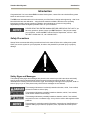
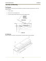
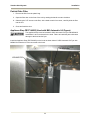
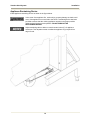
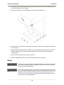
Ventless Hood System MODEL FH-28 Service Manual Serial Numbers 123046 and higher CS-TM-040.01 Revised 04/17/13 BKI LIMITED WARRANTY 2812 Grandview Dr. • Simpsonville, SC 29680 • USA (864) 963-3471 • Toll Free: (800) 927-6887 • Fax: (864) 963-5316 WHAT IS COVERED This warranty covers defects in material and workmanship under normal use, and applies only to the original purchaser providing that: The equipment has not been accidentally or intentionally damaged, altered or misused; The equipment is properly installed, adjusted, operated and maintained in accordance with national and local codes, and in accordance with the installation and operating instructions provided with this product. The serial number rating plate affixed to the equipment has not been defaced or removed. WHO IS COVERED This warranty is extended to the original purchaser and applies only to equipment purchased for use in the U.S.A. COVERAGE PERIOD Warranty claims must be received in writing by BKI within one (1) year from date of installation or within one (1) year and three (3) months from data of shipment from the factory, whichever comes first. COB Models: One (1) Year limited parts and labor. COM Models: Two (2) Year limited parts and labor. COM convection ovens also have a two (2) year door warranty. CO1 Models: Two (2) Year limited parts and labor. Five (5) Year limited door warranty. BevLes Products: Two (2) Year limited parts and labor. Warranty period begins the date of dealer invoice to customer or ninety (90) days after shipment date from BKI, whichever comes first. WARRANTY COVERAGE This warranty covers on-site labor, parts and reasonable travel time and travel expenses of the authorized service representative up to (100) miles round trip and (2) hours travel time and performed during regular, weekday business hours. EXCEPTIONS Any exceptions must be pre-approved in advance and in writing by BKI. The extended door warranty on convection ovens years 3 through 5 is a parts only warranty and does not include labor, travel, mileage or any other charges. EXCLUSIONS Negligence or acts of God, Thermostat calibrations after (30) days from equipment installation date, Air and gas adjustments, Light bulbs, Glass doors and door adjustments, Fuses, Adjustments to burner flames and cleaning of pilot burners, Tightening of screws or fasteners, Failures caused by erratic voltages or gas suppliers, Unauthorized repair by anyone other than a BKI Factory Authorized Service Center, Damage in shipment, Alteration, misuse or improper installation, Thermostats and safety valves with broken capillary tubes, Freight – other than normal UPS charges, Ordinary wear and tear, Failure to follow installation and/or operating instructions, Events beyond control of the company. INSTALLATION Leveling, as well as proper installation and check out of all new equipment per appropriate installation and use materials – is the responsibility of the dealer or installer, not the manufacturer. REPLACEMENT PARTS BKI genuine Factory OEM parts receive a (90) day materials warranty effective from the date of installation by a BKI Factory Authorized Service Center. CS-TM-040.01 Revised 04/17/13 Ventless Hood System Table of Contents Table of Contents Table of Contents ........................................................................................................................................1 Introduction..................................................................................................................................................2 Safety Precautions ....................................................................................................................................2 Safety Signs and Messages .................................................................................................................2 Specific Precautions .............................................................................................................................3 Safe Work Practices .............................................................................................................................3 Approvals Information ...............................................................................................................................5 Fusible Links .........................................................................................................................................5 Pressure/Open Fryers ..........................................................................................................................5 Sandwich Grills .....................................................................................................................................5 Fryers Specifications ............................................................................................................................6 Griddles Specifications .........................................................................................................................6 Installation....................................................................................................................................................7 Unpacking and Handling ...........................................................................................................................7 Inspection for Shipping Damage...........................................................................................................7 Location and Clearance........................................................................................................................7 Leveling.................................................................................................................................................8 Securing................................................................................................................................................9 Assembly and Mounting..........................................................................................................................10 Fire Damper ........................................................................................................................................10 Air Deflector ........................................................................................................................................10 Particle/Odor Filter ..............................................................................................................................11 Appliance Stop FB37144203 (Used with BKI Automatic Lift Fryers)..................................................11 Appliance Restraining Device.............................................................................................................12 Fire Extinguishing System ..................................................................................................................13 Wiring ......................................................................................................................................................14 Standard Electrical Connection ..........................................................................................................15 Appliance Electrical Connection .........................................................................................................16 Replacement Parts ....................................................................................................................................17 Assemblies ..............................................................................................................................................17 Accessories .............................................................................................................................................26 Wiring Diagrams ........................................................................................................................................27 Notes...........................................................................................................................................................28 1 Ventless Hood System Introduction Introduction Congratulations! You have chosen BKI’s Ventless Hood system, a state-of-the-art unit that filters grease laden air and returns it to the room. The BKI name and trademark on this unit assures you of the finest in design and engineering -- that it has been built with care and dedication -- using the best materials available. Attention to the operating instructions regarding proper operation, installation and maintenance will result in long lasting dependability to insure the highest profitable return on your investment. PLEASE READ THIS ENTIRE MANUAL BEFORE OPERATING THE UNIT. If you have any questions, please contact your BKI Distributor. If they do not answer your questions, contact the BKI Technical Service Department, toll free: 1-800927-6887. Outside the U.S., call 1-864-963-3471. Safety Precautions Always follow recommended safety precautions listed in this manual. Below is the safety alert symbol. When you see this symbol on your equipment, be alert to the potential for personal injury or property damage. Safety Signs and Messages The following Safety signs and messages are placed in this manual to provide instructions and identify specific areas where potential hazards exist and special precautions should be taken. Know and understand the meaning of these instructions, signs, and messages. Damage to the equipment, death or serious injury to you or other persons may result if these messages are not followed. This message indicates an imminently hazardous situation, which, if not avoided, will result in death or serious injury. This message indicates a potentially hazardous situation, which, if not avoided, could result in death or serious injury. This message indicates a potentially hazardous situation, which, if not avoided, may result in minor or moderate injury. It may also be used to alert against unsafe practices. This message is used when special information, instructions or identification are required relating to procedures, equipment, tools, capacities and other special data. 2 Ventless Hood System Introduction Specific Precautions Carbon monoxide poisoning will result from using this hood with any appliance that utilizes combustible fuel. Use only electrical appliances with this hood. In the event of an appliance fire, serious injury, property damage or death could occur if the appliance is not properly secured to the hood. A restraining device has been provided to assure that the appliance remains in the proper position under the hood during normal operation. DO NOT REMOVE THE RESTRAINING DEVICE! Hood failure could result if the hood is operated without the grease baffle and particle/odor filter installed. This is a special filter designed for this application only; other filters will not work properly. Use only a BKI particle/odor filter. Safe Work Practices Beware of High Voltage This equipment uses high voltage. Serious injury can occur if you or any untrained or unauthorized person installs, services, or repairs this equipment. Always Use an Authorized Service agent to Service Your Equipment Keep this manual with the Equipment This manual is an important part of your equipment. Always keep it near for easy access. If you need to replace this manual, contact: BKI Technical Services Department 2812 Grandview Drive Simpsonville, S.C. 29680 Or call toll free: 1-800-927-6887 Outside the U.S., call 864-963-3471 Protect Children Keep children away from this equipment. Children may not understand that this equipment is dangerous for them and others. NEVER allow children to play near or operate your equipment. 3 Ventless Hood System Introduction Keep Safety Labels Clean and in Good Condition Do not remove or cover any safety labels on your equipment. Keep all safety labels clean and in good condition. Replace any damaged or missing safety labels. If you need new safety labels, contact: BKI Technical Services Department 2812 Grandview Drive Simpsonville, S.C. 29680 Or call toll free: 1-800-927-6887 Outside the U.S., call 864-963-3471 Prepare for Emergencies Be prepared for fires, injuries, or other emergencies. 911 Keep a first aid kit and a fire extinguisher near the equipment. You must use a 40-pound Type BC fire extinguisher and keep it within 25 feet of your equipment. Keep emergency numbers for doctors, ambulance services, hospitals, and the fire departments near your telephone. Know your responsibility as an Employer • Make certain your employees know how to operate the equipment. • Make certain your employees are aware of the safety precautions on the equipment and in this manual. • Make certain that you have thoroughly trained your employees about operating the equipment safely. • Make certain the equipment is in proper working condition. If you make unauthorized modifications to the equipment, you will reduce the safety and function of the equipment. 4 Ventless Hood System Introduction Approvals Information Failure to adhere to building, fire and electrical codes during installation of this unit could result in death, serious injury or property damage. The authority having jurisdiction, such as the local building inspector or fire marshal, should be consulted prior to installation to insure compliance with applicable codes. In the event of an appliance fire, serious injury, property damage or death could occur if the appliance is powered from a source other than the hood. The cooking appliance used under this hood MUST receive its input power from the hood. Electricity is automatically removed from the hood and the appliance when the Fire Extinguishing System is activated. In the event of an appliance fire, serious injury, property damage or death could occur if the remote pull station is not properly installed. The remote pull is to be clearly marked, located in a path of exit or egress and must comply with applicable codes. It is the responsibility of the owner to verify that the cooking appliance is eligible for use with this hood. This filter hood is an ETL Listed ductless hood for use with Listed commercial cooking appliances only (griddle or fryer). Fusible Links • Fusible links to be UL Listed, 165° F., load rating 3-45 lbs. Pressure/Open Fryers • Pressure fryers acceptable for use with this hood shall be constructed such that when the lid is released or unlatched it shall spring to the fully open position within four seconds. Fully open is defined as vertical, upright position (80° or more) from the closed position. The lid must open without operator or electrical assistance, toward the back of the hood. • The lid of the pressure fryer, when it is open, shall not block fire-extinguishing nozzle from the vat. • The lid of a pressure fryer should be checked for proper operation at least once a month. If the lid fails to fully open when unlatched or released, it should be repaired immediately by factory authorized service personnel. Do not operate a fryer with a defective lid opening mechanism. • Fryers with lids (other than pressure fryers) shall be operated only with the lid removed. Lids may be used for covering the vat when power to the cooking appliance and hood has been turned off. Sandwich Grills • Sandwich grills acceptable for use with this hood shall be used such that when the lid is either fully open, released, or unlatched it shall spring to the fully open position. Fully open is defined as vertical, upright position (80° or more) from the closed position. The lid must open toward the back of the hood. The lid of a sandwich grill, when open shall not block fire extinguishing nozzles from the cooking surface. 5 Ventless Hood System Introduction Fryers Specifications Volts 208/240 Phase 1 or 3 Maximum Amps 60 Maximum Input 22 KW (3ph) 14.4 KW (1ph) Frequency 60 Hz Maximum normal frying temperature 375° F. (191° C.) Maximum shortening capacity 110 lbs. (50kg.) Maximum cooking surface area 396 sq. in. (2555 sq. cm.) USE ELECTRIC FRYERS AND SINGLE VAT FRYERS ONLY Griddles Specifications Volts 208/240 Phase 1 or 3 Maximum Amps 38.5 Maximum Input 8 KW Frequency 60 Hz Maximum griddle surface area 450 sq. in. (2903 sq. cm.) Maximum cooking surface temperature 450° F. (232° C.) USE ELECTRIC GRIDDLES ONLY 6 Ventless Hood System Installation Installation Serious injury, equipment damage or death could result if attempting to install this unit yourself. Ensure that an authorized BKI service agent installs the unit. Unpacking and Handling Inspection for Shipping Damage YOU are responsible for filing all freight claims with the delivering truck line. Inspect all cartons and crates for damage as soon as they arrive. If damage to cartons or pallets is found, or if a shortage is found, note this on the bill of lading (all copies) prior to signing and receiving. If damage is found when the equipment is opened, immediately call the delivering truck line and follow up the call with a written report indicating concealed damage to your shipment. Ask for an immediate inspection of your concealed damage item. Packaging material MUST be retained to show the inspector from the shipping line. Location and Clearance Place the Filter Hood in a location with clearance as shown in the figure and data below. These distances provide for proper clearance to combustible surfaces, access for maintenance, and proper air flow from hood exit vent. MINIMUM CLEARANCE HOOD TO COMBUSTIBLE 18 in. (FH-28) SIDES, 0 in. BACK, 0 in. TOP, 0 in. BOTTOM NON-COMBUSTABLE REAR WALL REQUIRED FOR FH-28 WALL MOUNT APPLIANCE CLEARANCE Vat to sides of hood: 6.25 in. (FH-28) Griddle to sides of hood: 0 in., Sandwich grills to sides of hood: 6 in. Cooking surface must be at least 3.5 inches behind the front edge of the hood. Appliance cabinet top or cooking surface to be level with bottom of hood sides ± 3 in. 7 Ventless Hood System Installation Leveling 1. Adjust the four feet provided on the bottom of the unit so there is a minimum of 6” clearance below the frame side members (NSF REQUIREMENTS). 2. Check for level from side to side and front to back using a 4’ level placed appropriately on the frame. 8 Ventless Hood System Installation Securing Wall Mount After the hood has been located and leveled, secure to building by utilizing the .437 diameter holes provided in the rear of the fire extinguisher cylinder shelf (Refer to figure below). Using 1/4” lag screw(s), spacer(s) (if required), and anchor(s) (if required) secure the hood to a wall to prevent movement. The outside holes are spaced at 16 inches in the event wall studs can position the unit. Brace Mount If the unit is being mounted far away from a wall, a brace (angle) secured to the floor may be bolted to the shelf. This brace must be sufficient to prevent movement of the hood. Seal brace connection to floor using a food grade RTV. This will prevent grease or food particles from getting beneath the brace. 9 Ventless Hood System Installation Assembly and Mounting Fire Damper A UL Listed 165° F fusible link must be installed in the damper assembly located at the top of the unit. Install as follows: 1. Lift the damper. 2. Place the link on the damper hook. 3. Lower the damper while placing the link onto the stationary hook. Air Deflector Mount air deflector, as shown in the figure below, using two knurled screws (provided). 10 Ventless Hood System Installation Particle/Odor Filter 1. Remove the filter from the plastic bag. 2. Open the filter door on the front of the unit by rotating the handle counter-clockwise. 3. Observing the “UP” arrows on the filter, with a hand at each front corner, carefully slide the filter into the unit. 4. Close and latch the door. Appliance Stop FB37144203 (Used with BKI Automatic Lift Fryers) The Appliance Stop must be installed if a BKI Automatic Lift Fryer with M0084 lift mechanism is to be connected to the hood. Failure to install this part could cause damage to the hood and/or fryer. Install the Appliance Stop (FB37144203) on the hood as shown below if a BKI Automatic Lift Fryer with M0084 lift mechanism is to be connected to the hood. 11 Ventless Hood System Installation Appliance Restraining Device Install appliance-restraining device as shown in the figure below. In the event of an appliance fire, serious injury, property damage or death could occur if the appliance is not secured to the hood. A restraining device has been provided to assure that the cooking appliance remains in the proper position under the hood during normal operation. DO NOT REMOVE THE RESTRAINING DEVICE! Adjust restraining cable to allow no more than two inches (2”) of appliance movement. This adjustment must not allow the appliance to go beyond front edge of hood. 12 Ventless Hood System Installation Fire Extinguishing System In the event of an appliance fire, serious injury, property damage or death could occur if any part of the appliance obstructs the spray nozzles. Ensure that lids and/or other parts of the appliance do not obstruct the spray pattern of either nozzle. The fire extinguishing system components used in this hood have been evaluated by U.L. in the course of their classification for use on this hood. An authorized Range Guard distributor must install and activate the filter hood fire extinguishing system. To locate an authorized Range Guard Distributor use the following contact information: Badger Fire Protection 944 Glenwood Station Lane, Suite 303 Charlottesville VA. 22901 Office: 800-446-3857 Fax: 800-248-7809 www.badgerfire.com 1. After the hood has been properly secured to prevent movement, locate the end-of-line remote pull station (at a point of egress or exit) in a manner approved by the local authority and in accordance with applicable codes. To install the end-of-line remote, use ½” EMT and Range Guard corner pulleys #97915. 2. Install two UL Listed; type “A”, 165° F. fusible links (load rating 3-45 lbs.) in the two appliance detector positions (one in front of the grease baffle, one behind the grease baffle). FUSIBLE LINKS 13 Ventless Hood System Installation 3. If required, connect the provided fire extinguishing system contacts for remote signaling (refer to the electrical diagram in this manual). 4. Adjust the position of the two ADP appliance nozzles as depicted below. 5. Reset control head. With control head NOT connected to cylinder, dry test system by activating the remote pull. 6. Install cylinder by placing bottom of cylinder over socket head screws at the bottom of cylinder bracket. Tighten pipe union located in the discharge line. Secure cylinder with adjustable clamping strap. 7. Reset control head and connect control to cylinder. 8. Recheck installation procedure to insure that nothing has been overlooked. Wiring Electrocution, equipment failure or property damage could result if an unlicensed electrician performs the electrical installation. Ensure that a licensed electrician perform the electrical installation. In the event of an appliance fire, serious injury, property damage or death could occur if the appliance is powered from a source other than the hood. The cooking appliance used under this hood MUST receive its input power from the hood. In the event of a fire, the hood fire extinguishing system will automatically remove power from the connected appliance. 14 Ventless Hood System Installation The fire extinguishing system must be operative before the electrical system will function. Refer to the electrical diagram included in this manual (see page 27). Standard Electrical Connection This connection is for Listed appliances supplied with a cord and a NEMA style 15-60 right angle plug. 1. Remove fire extinguisher access panel. 2. Route incoming power lines through holes located in the top of the 12”x8”x4” electrical enclosure. 3. Connect ground to the lug provided inside the enclosure. 4. Perform the applicable step below: • For single-phase operation, connect incoming power to terminals L1 and L2 of the contactor. • For three-phase operation, connect incoming power to terminals L1, L2 and L3 of the contactor. 5. Replace electrical box cover and fire extinguisher access panel 6. Insert plug into receptacle located in the hood. 7. Install cover over plug. 15 Ventless Hood System Installation Appliance Electrical Connection This connection is for appliances requiring a Listed flexible conduit connection (refer to figure below). 1. Remove receptacle and four wires (T1, T2, T3, and Ground). 2. Cover junction box hole with provided plate and hardware removed from receptacle. 3. Remove hole plug from hole in bottom of electrical enclosure and install conduit from appliance utilizing appropriate Listed fitting (not provided). 4. Wire appliance as shown in figure below and the electrical diagram in this manual. 5. Replace all panels and install cover over hole that was provided for the receptacle (now removed) 16 Ventless Hood System Replacement Parts Replacement Parts Use the information in this section to identify replacement parts. To order replacement parts, call your local BKI sales and service representative. Before calling, please note the serial number on the rating tag affixed to the unit. Assemblies Description Figure # Table # Electrical Box Assembly Figure 1 Table 1 Blower Motor Assembly Figure 2 Table 2 Right Side Cabinet Assembly Figure 3 Table 3 Fire Piping System Assembly Figure 4 Table 4 Cylinder/ELL/Bushing Assembly Figure 5 Table 5 Fire Detection System Assembly Figure 6 Table 6 17 Ventless Hood System Replacement Parts Figure 1. Electrical Box Assembly 18 Ventless Hood System Replacement Parts Table 1. Electrical Box Assembly Parts List ITEM # 1 2 3 4 5 6 7 8 9 10 11 12 13 14 15 PART # SCR030 SCR118 RC0009 WB37112900 NUT048 NUT051 F0336 F0100 FT0322 FH0001 FH0006 R0129 WSH089 WSH090 F0111 QTY DESCRIPTION SCREW, 10-24 X 1/2 PHIL RD HD SCREW, 6-32 X 5/8 SLTD RD HD RECEPTACLE, FLUSH 60A 250V JUNCTION BOX WELD, FH NUT, 6-32 HEX ZINC PLTD NUT, 10-24 HEX ZINC PLTD FUSE, 5A 250V FNM5 TIME DELAY FUSE, 1A 300V SC-1 TIME DELAY PLUG, ELEC 3P4W 60A 250V FUSE HOLDER, 15A 300V HPF-EE FUSE HOLDER, 30A 600V HPF RELAY, 3POLE 60A 208/240 50/60 WASHER, #6 INT LOCK ZINC PLATED WASHER, #10 LOCK ZINC PLATED TERMINAL GROUNDING LUG 7 8 1 1 8 7 2 2 1 2. 2 1 8 7 2 19 Ventless Hood System Replacement Parts Figure 2. Blower Motor Assembly 20 Ventless Hood System Replacement Parts Figure 2. Blower Motor Assembly – Continued Table 2. Blower Motor Assembly Parts List ITEM # 1 2 3 4 5 6 7 8 9 10 11 12 13 14 15 PART # M0052 F0024 TP0021 WSH037 NUT049 SP0013 FN0005 FN0004 OR FN0019 FB37115200 FT0320 FN0006 OR FN0020 FN0007 SCR004 FB37113602 SCR137 QTY 1 16 36” 4 8 4 1 1 OR 1 1 2 1 OR 1 1 6 1 8 DESCRIPTION MOTOR, BLOWER 1/2 HP LEESON RIVNUT, #10-24 TAPE, ARMAFLEX 1/8 X 3/4 X 50' WASHER, 3/16 SAE FLAT NUT, 8-32 HEX SPACER, FOR #8 X 1/2" LG. HOUSING, BLOWER CLOCKWISE WHEEL, BLOWER 5 3/4 CLKWS RT. OR BLOWER WHEEL, 50HZ FH HOODS CONDUIT, 1/2" FT0323 10" COMPRESSION FTG, 1/2" STRAIGHT WHEEL, BLOWER 5-3/4 CTCKWS LT OR BLOWER WHEEL, 50 HZ FH HOODS HOUSING, BLOWER C'TR CLK WISE SCREW, 8 X 3/8 PHIL TRUSS HD PLATE, LEESON FAN MOUNTING SCREW, 10-24 X 5/8 SLTD TRUSS 21 Ventless Hood System Replacement Parts Figure 3. Right Side Cabinet Assembly 22 Ventless Hood System Replacement Parts Figure 3. Right Side Cabinet Assembly – Continued Table 3. Right Side Cabinet Assembly Parts List ITEM # 1 2 3 4 5 6 7 8 9 10 11 12 13 PART # S0097 S0098 S0099 S0101 SCR289 NUT051 WSH090 PL0004 S0073 S0310 S0307 S0311 S0306 QTY 1 1 1 1 8 8 8 1 2 1 1 1 1 23 DESCRIPTION SWITCH, VACUUM 371 SWITCH, VACUUM 371 SWITCH, VACUUM 371 SWITCH, VACUUM 371 SCREW, 10-32 X 1/2 PHIL TRUSS NUT, 10-24 HEX ZINC PLTD LOCK WASHER, SWITCH MOUNTING PILOT LIGHT, ROUND 250V SWITCH, PUSHBUTTON MICRO SWITCH, FLUSH GREEN PUSH SWITCH, NO BLOCK GE P9B10VN SWITCH, EXTENDED RED PUSH SWITCH, NC BLOCK GE P9B01VN Ventless Hood System Replacement Parts Figure 4. Fire Piping System Assembly Parts 1 2 3 4 5 6 7 8 9 10 11 12 13 14 15 16 17 18 19 20 21 22 23 24 25 26 27 24 Ventless Hood System Replacement Parts Table 4. Fire Piping System Assembly Parts List ITEM# 1 2 3 4 5 6 7 8 9 10 11 12 13 14 15 16 17 18 19 20 21 22 23 24 25 26 27 PART # FE0007 FE0019 FE0023 FE0031 FE0039 FE0040 FT0218 FT0219 FT0220 FT0221 FT0222 FT0281 FT0283 FT0331 FT0334 FT0336 FT0338 FT0339 FT0340 FT0341 FT0342 FT0343 FT0344 FT0345 FT0347 FT0419 FT0431 QTY 2 2 2 1 2 2 1 1 1 8 1 2 1 1 2 3 1 1 2 1 2 1 1 1 1 2 2 DESCRIPTION AFS 3/8" QUICK SEAL LIQUID SEAL ADAPTER 1/2" (FH/LFH) NOZZLE, 0.2 FLOW POINT PLUG,VENT 1/2NPT MALE KIDDE LFH42/63 SWIVEL ADAPTER B120021 NOZZLE ADP 3/8 F THREAD NIPPLE, 1/4 X 2 BLK NIPPLE, 1/4 X 4 BLK UNION, 1/4" BLK ELL, 1/4 90 DEG BLACK NIPPLE, 1/4 X C BLK TEE, 1/4" BLACK COUPLING, ¼ X 1/2 REDUCING CROSS, 1/4" BLACK PIPE BUSHING, 1/2 X 1/4 REDUCING NIPPLE, 1/4 X 3 1/2 NIPPLE, 1/4 X 3 BLK NPT NIPPLE, 1/4 X 42 1/2 BLACK NIPPLE, 1/4 X 4 1/2 BLACK NIPPLE, 1/4 X 8 3/4 BLACK NIPPLE, 1/4 X 26 3/4 NIPPLE, 1/4 X 8 BLACK NIPPLE, 1/4 X 6 1/4 BLACK ELL, STREET 1/4 NPT 90 DEG NIPPLE, 1/4 X 5 BLACK NIPPLE, 3/8 CLOSE SS SCH40 BUSHING, 3/8 - 1/4 REDUCING Figure 5. Cylinder/ELL/Bushing Assembly Parts 1 2 3 5 6 7 ITEM # 1 2 3 4 5 6 7 4 Table 5. Cylinder/ELL/Bushing Assembly Parts List PART # QTY DESCRIPTION FB37139102 1 FIRE TANK SEAL, FH HOOD FE0011 1 CYLINDER, 1.25 GAL FE0037 1 REDUCING ADAPTER FOR FE0011 FT0220 1 UNION, 1/4" BLK FT0222 1 NIPPLE, 1/4 X C BLK FT0345 1 ELL, STREET 1/4 NPT 90 DEG O0024 1 O-RING, .139 X .984 ID 25 Ventless Hood System Replacement Parts Figure 6. Fire Detection System Assembly Parts 1 2 3 4 5 6 7 8 9 10 Table 6. Fire Detection System Assembly Parts List ITEM # 1 2 3 4 5 6 7 8 9 10 PART # FA37110400 FB37110600 FB37139302 FE0017 FE0041 FE0042 FT0288 FT0554 MB37139500 MB37139600 QTY 1 1 1 2 1 1 1 1 1 1 DESCRIPTION CONDUIT, 1/2 EMT 1.375" CONDUIT, 1/2 EMT 11.625" BRACKET,FH A+ CONT.HEAD MOUNT PULLEY, FIRE SYS FH/LFH CONTROL BOX,A+,(CO2) BADGER MICROSWITCH KIT, A+ CONTROL COMPRESSION FITTING 1/2-1/2NPT COMPRESSION FITTING BRASS CONDUIT,EMT 31"FH TUBING,1/4"COPPER,24"FH Accessories PART # FI0024 Or FI0025 FB37144203 QTY 1 1 DESCRIPTION FILTER, FIBERGLASS FH Or FILTER, HIGH CARBON FH APPLIANCE STOP 26 PICTURE Ventless Hood System Wiring Diagrams Wiring Diagrams 27 Ventless Hood System Notes Notes 28 2812 Grandview Dr., Simpsonville, S.C. 29680, USA http://www.bkideas.com Made and printed in the U.S.A LI0191/0908 CS-TM-040.01 Revised 04/17/13 Ventless Hood System REVISION HISTORY REVISION 01 DATE 04/17/13 REVISED BY KW 2 DESCRIPTION Initial Release-Supersedes all previous releases