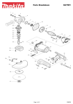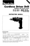
1
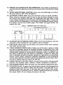
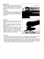
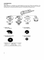
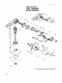
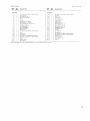
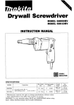
Disc Grinder
125 mm (5") MODEL 9505BH
INSTRUCTION MANUAL
DOUBLE
INSULATION
SPEC IF ICAT IONS
No load speed
~~~
..
iRPMi
Overall length
10.000
2 6 0 mtn 110 1 4")
Net weight
Spindle thread
2 1 kg 14.6 Ibs)
5/8"
-
lMPORTANT
SAFETY INSTRUCTlONS
(For All Tools)
WARNING: WHEN USING ELECTRIC TOOLS, BASIC SAFETY
PRECAUTIONS SHOULD ALWAYS BE FOLLOWED TO REDUCE
THE RISK OF FIRE, ELECTRIC SHOCK, AND PERSONAL
INJURY, INCLUDING THE FOLLOWING:
READ ALL INSTRUCTIONS.
1. KEEP WORK AREA CLEAN. Cluttered areas and benches invite injuries.
2. CONSIDER WORK AREA ENVIRONMENT. Don't use power tools in damp
or wet locations. Keep work area well lit. Don't expose power tools t o rain.
Don't use tool in presence of flammable liquids or gases.
3. KEEP CHILDREN AWAY. All visitors should be kept away from work area.
Don't let visitors contact tool or extension cord.
4. STORE IDLE TOOLS. When not in use, tools should be stored in dry, and high
or locked-up place - out of reach of children.
5. DON'T FORCE TOOL. It will do the job better and safer at the rate for which
it was intended.
6. USE RIGHT TOOL. Don't force small tool or attachment t o do the job of a
heavy-duty tool. Don't use tool for purpose not intended; for example, don't
use circular saw for cutting tree limbs or logs.
7. DRESS PROPERLY. Don't wear loose clothing or jewelry. They can be caught
in moving parts. Rubber gloves and non-skid footwear are recommended
when working outdoors. Wear protective hair covering t o contain long hair.
8. USE SAFETY GLASSES. Also use face or dust mask if cutting operation is
dusty.
9. DON'T ABUSE CORD. Never carry tool by cord or yank it t o disconnect from
receptacle. Keep cord from heat, oil, and sharp edges.
IO. SECURE WORK. Use clamps or a vise t o hold work. It's safer than using
your hand and it frees both hands t o operate tool.
1 1 . DON'T OVERREACH. Keep proper footing and balance at all times.
12. MAINTAIN TOOLS WITH CARE. Keep tools sharp and clean for better and
safer performance. Follow instructions for lubricating and changing accessories. Inspect tool cords periodically and if damaged, have repaired by authorized service facility. Inspect extension cords periodically and replace if
damaged. Keep handles dry, clean, and free from oil and grease.
13. DISCONNECT TOOLS. When not in use, before servicing, and when changing accessories, such as blades, bits, cutters.
2
I
14. REMOVE ADJUSTING KEYS AND WRENCHES. Form habit of checking to
see that keys and adjusting wrenches are removed from tool before turning
it on.
15. AVOID UNINTENTIONALSTARTING. Don't carry tool with finger on switch.
Be sure switch is OFF when plugging in.
16. EXTENSION CORDS. Make sure your extension cord is in good condition.
When using an extension cord, be sure t o use one heavy enough t o carry
the current your product will draw. An undersized cord will cause a drop
in line voltage resulting in loss of power and overheating. Table 1 shows the
correct size t o use depending on cord length and nameplate ampere rating.
If in doubt, use the next heavier gage. The smaller the gage number, the
heavier the cord.
TABLE 1 MINIMUM GAGE FOR CORD SETS
0
- 25
26 - 50
Ampere Rating
More
Not More
Than
Than
0
6
10
12
-
-
6
10
12
16
51
- 100
101 - 150
A W G
18
18
16
14
16
16
16
12
14
14
12
Not Recommended
17. OUTDOOR USE EXTENSION CORDS. When tool is used outdoors, use only
extension cords intended for use outdoors and so marked.
18. STAY ALERT. Watch what you are doing, use common sense. Don't operate
tool when you are tired.
19. CHECK DAMAGED PARTS. Before further use of the tool, a guard or other
part that is damaged should be carefully checked t o determine that it will
operate properly and perform its intended function. Check for alignment of
moving parts, binding of moving parts, breakage of parts, mounting, and
any other conditions that may affect its operation. A guard or other part
that is damaged should be properly repaired or replaced by an authorized
service center unless otherwise indicated elsewhere in this instruction
manual. Have defective switches replaced by authorized service center. Don't
use tool if switch does not turn it on and off.
20. GUARD AGAINST ELECTRIC SHOCK. Prevent body contact with grounded
surfaces. For example; pipes, radiators, ranges, refrigerator enclosures.
2 1. REPLACEMENT PARTS. When servicing, use only identical replacement parts.
22. POLARIZED PLUGS. To reduce the risk of electric shock, this equipment has
a polarized plug (one blade is wider than the other). This plug will fit in a
polarized outlet only one way. If the plug does not fit fully in the outlet,
reverse the plug. If it still does not fit, contact a qualified electrician t o install
the proper outlet. Do not change the plug in any way.
3
VOLTAGE WARNING: Before connecting the tool t o a power source (receptacle,
outlet, etc.) be sure the voltage supplied is the same as that specified on the
nameplate of the tool. A power source with voltage greater than that specified
for the tool can result in SERIOUS INJURY t o the user - as well as damage t o
the tool. If in doubt, DO NOT PLUG IN THE TOOL. Using a power source with
voltage less than the nameplate rating is harmful t o the motor.
ADDITIONAL SAFETY RULES
1. Keep guards in place.
2. Use only wheels having a maximum operating speed at least as high as "No
Load RPM" marked on the tool's nameplate. When using depressed center
wheels, be sure t o use only fiberglass-reinforced wheels.
3. Check the wheel carefully for cracks or damage before operation. Replace
cracked or damaged wheel immediately.
4. Use only flanges specified for this tool.
5. Be careful not t o damage the spindle, the flange (especially the installing
surface) or the lock nut. Damage t o these parts could result in wheel
breakage.
6. Hold the tool firmly.
7. Keep hands away from rotating parts.
8. Make sure the wheel is not contacting the workpiece before the switch is
turned on.
9. Before using the tool on an actual workpiece, let it run for a while. Watch
for vibration or wobbling that could indicate poor installation or a poorly
balanced wheel.
IO. Use the specified surface of the wheel t o perform the grinding.
11. Watch out for flying sparks. Hold the tool so that sparks fly away from you
and other persons or flammable materials.
12. Do not leave the tool running. Operate the tool only when hand-held.
13. Do not touch the workpiece immediately after operation; it may be extremely
hot and could burn your skin.
SAVE THESE INSTRUCTIONS.
4
Installing side grip (auxiliary handle)
Screw the side grip on the tool securely.
The side grip can be installed on either side
of the tool, whichever is convenient.
I
1
Installing or removing depressed center wheel
CAUTION :
Always be sure that the tool i s switched off and unplugged before installing or removing
the wheel.
Mount the inner flange onto the spindle.
Fit the wheel on over the inner flange and
screw the lock nut orito the spindle.
I
I
DeDressed
I
I
I
I
I
I
I
To tighten the lock nut, press the shaft
lock firmly so that the spindle cannot revolve, then use the lock nut wrench and
securely tighten clockwise.
I
/
Shaft lock
To remove the wheel, follow the installation procedure in reverse.
5
Switch action
Slide the slide switch forward to start, and
the switch will lock in the "ON" position.
To stop, lgihtly depress the rear of the
switch, and it will return to the "OFF"
position.
Slide switch
CAUTION :
Before plugging in the tool, always check
to see that the switch actuates properly
and returns to the "OFF" position when
depressed.
Operation
Hold the tool firmly. Turn the tool on and
then apply the wheel or disc to the workpiece.
In general, keep the edge of the wheel or
disc a t an angle of about 15" to the workpiece surface.
During the break-in period with a new
wheel, do not work the grinder in the B
direction or it will cut into the workpiece.
Once the edge of the wheel has been
rounded off by use, the wheel may be
worked in both A and B directions.
WARNING :
0 It should never be necessary to force the tool. The weight of the tool applies adequate
pressure. Forcing and excessive pressure could cause dangerous wheel breakage.
.Continued use of a worn-out wheel may result in wheel explosion and serious personal
injury. Depressed center wheel should not be used after it has been worn down to
90 mm (3-1/2")in diameter. Use of the wheel after this point i s unsafe and it should be
removed from service and rendered unusable by intentional destruction.
6
MAINTENANCE
CAUTION :
Always be sure that the tool is switched off and unplugged before attempting to perform
inspection or maintenance.
Replacing carbon brushes
Remove and check the carbon brushes
regularly. Replace when they wear down
to the limit mark. Keep the carbon brushes
clean and free to slip in the holders. Both
carbon brushes should be replaced a t the
same time. Use only identical carbon
brushes.
Use a screwdriver t o remove the brush
holder caps. Take out the worn carbon
brushes, insert the new ones and secure
the brush holder caps.
I
I
To maintain product SAFETY and RELIABILITY, repairs, any other maintenance or
adjustment should be performed by Makita Authorized or Factory Service Centers,
always using Makita replacement parts.
7
ACCESSORIES
CAUTION :
These accessoires or attachments are recommended for use with your Makita tool specified in this
manual. The use of any other accessories or attachments might present a risk of injury to persons.
The accessories or attachments should be used only in the proper and intended manner.
0 Wheel cover
Part No. 164556-8
@ Depressed center wheels
(5 wheels per pkg)
8
@
Inner flange 82
Part No. 224178-7
@ Lock nut 5/8-40
Part No. 224509-0
0 Multi disc
I
Part No.
794331 -4A
794331- 4 8
I
Size (mm)
Grit
125 x 17 x 22.2
794331 -4D
100
@
@ Abrasive discs
(5discs per pkg)
Locknut 5 / 8 - 4 8
(For abrasive disc)
Part No. 224517-1
8 Urethane washer
14
Part No. 261039-0
Part No.
742072-A-5
742073-A-5
742074-A-5
742075-A-5
742076-A-5
0
Grip 2 6
Part No. 273485-5
0
Steel carrying case
Part No.
181717-5
Grit
24
30
50
80
120
When using wire brush, mount urethane
wahser 14 t o the spindle. It w i l l make it
easier t o remove wire brush.
@
Wire cup brush
Part No. 743205-6
0
Lock nut wrench 2 8
Part No. 782413-4
9
Sep
2 2 ' 8 7 US
125 mm (5")
DISC GRINDER
Model 9505BH
Note: The switch and other part configurations
may differ from country to country.
10
MODEL 9 5 0 5 E H
ITEM
NO
NO
USED
Sep
DESCRIPTION
I:,',"
,":,
DESCRIPTION
MACHIN!
1
2
3
4
5
4
1
7
1
1
1
1
1
8
2
9
1
1
1
1
1
2
6
10
11
12
13
16
17
18
19
20
21
22
24
25
1
1
1
2
2
1
1
1
-
Pan Head Srrew M 4 x 2 0 1With Wa<herl
G e a r Housing
Spiral Bevel Gear 1 1
Ball Bearing 6000LE
Plate
Fan 6 0
ARMATURE ASSEMBLY
I W i l h Item 6 7 9 & 101
Hex Bolt M 4 x 7 0 [With Washer1
Insulation Washer
Ball Bearing 627LB
FIELD ASSEMBLY
Motor Housing
Rubber Pin 4
Pan Head S c r e w M 4 x 6 0 l W i f h Washer1
Cord
Rear Cover
Cord Guard
Pan Head Screw M 4 x 8 IWifh Washeri
Pan Head Screw M 4 x 1 4 l W i f h Washer1
Switch
Switch Holder
Strain Relief
26
27
28
29
30
31
32
33
34
35
36
37
2
1
4
1
2
2
1
1
1
1
1
1
38
39
40
41
42
43
44
1
1
1
4
1
45
46
100
1
1
1
1
1
- -
Note The Switch and other part specificattons m a y differ from c o ~ n l r yIo Country
P a n Head Screw M 4 x 1 4 IWilti Wdsherl
Set Plate
Rivet 0 5
Name Plate
Brush Holder Cap
Carbon Brush
S w i t c h Lever
Woodruff Key 3
Retaining Ring S 1 2
Spiral Bevel Gear 3 6
Retaining Ring R 32
BalPBearing 6 2 0 1 LB
Flat Washer 1 2
Spindle
Felt Ring 1 8
Bearing Box
P a n Head Screw M 4 x 1 4 I W i l h WaSheri
Pan Head Screw M 5 x 1 4 IWith Washer1
Wheel Cover
Inner Flange 8 2
Lock Nut 518 4 0
Grip 26
22
87 US
P
MAKITA LIMITED ONE YEAR WARRANTY
Warranty Policy
Every Makita tool is thoroughly inspected and tested before leaving the factory. It is warranted to
be free of defects from worbnanship and materials for the period of ONE YEAR from the date of
original purchase. Should any trouble develop during this one-year period, return the COMPLETE
tool, freight prepaid, to one of Makita’s Factory or Authorized Service Centers. If inspection shows
the trouble is caused by defective workmanship or material, Makita will repair (or at our option,
replace) without charge.
This Warranty does not apply where:
e repairs have been made or attempted by others:
e repairs are required because of normal wear and tear:
e The tool has been abused, misused or improperly maintained;
e alterations have been made to the tool.
IN NO EVENT SHALL MAKITA BE LIABLE FOR ANY INDIRECT, INCIDENTAL OR CONSEQUENTIAL DAMAGES FROM THE SALE OR USE O F THE PRODUCT. THIS DISCLAIMER
APPLIES BOTH DURING AND AFTER THE TERM O F THIS WARRANTY.
MAKITA DISCLAIMS LIABILITY FOR ANY IMPLIED WARRANTIES, INCLUDING IMPLIED
WARRANTIES O F “MERCHANTABILITY” AND “FITNESS FOR A SPECIFIC PURPOSE,”
AFTER THE ONE-YEAR TERM O F THIS WARRANTY.
This Warranty gives you specific legal rights, and you may also have other rights which vary from
state to state. Some states d o not allow the exclusion or limitation of incidental or consequential
damages, so the above limitation or exclusion may not apply to you. Some states d o not allow
limitation on how long an implied warranty lasts, so the above limitation may not apply to you.
-
-
Makita Corporation
3-11-8, Sumiyoshi-cho,
Anjo, Aichi 446 Japan
883432C066
PRINTED IN JAPAN
I995 - 4 - N