1
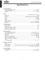
MODEL M1039 12-SPEED DRILL PRESS OWNER'S MANUAL Phone: (360) 734-3482 • On-Line Technical Support: [email protected] COPYRIGHT © FEBRUARY, 2006 BY WOODSTOCK INTERNATIONAL, INC. REVISED JULY, 2008 (TR) #7894JK WARNING: NO PORTION OF THIS MANUAL MAY BE REPRODUCED IN ANY SHAPE OR FORM WITHOUT THE WRITTEN APPROVAL OF WOODSTOCK INTERNATIONAL, INC. Printed in China This manual provides critical safety instructions on the proper setup, operation, maintenance, and service of this machine/tool. Save this document, refer to it often, and use it to instruct other operators. Failure to read, understand and follow the instructions in this manual may result in fire or serious personal injury—including amputation, electrocution, or death. The owner of this machine/tool is solely responsible for its safe use. This responsibility includes but is not limited to proper installation in a safe environment, personnel training and usage authorization, proper inspection and maintenance, manual availability and comprehension, application of safety devices, cutting/sanding/grinding tool integrity, and the usage of personal protective equipment. The manufacturer will not be held liable for injury or property damage from negligence, improper training, machine modifications or misuse. Some dust created by power sanding, sawing, grinding, drilling, and other construction activities contains chemicals known to the State of California to cause cancer, birth defects or other reproductive harm. Some examples of these chemicals are: • Lead from lead-based paints. • Crystalline silica from bricks, cement and other masonry products. • Arsenic and chromium from chemically-treated lumber. Your risk from these exposures varies, depending on how often you do this type of work. To reduce your exposure to these chemicals: Work in a well ventilated area, and work with approved safety equipment, such as those dust masks that are specially designed to filter out microscopic particles. ELECTRICAL SET UP OPERATIONS MAINTENANCE SERVICE PARTS USE THE QUICK GUIDE PAGE LABELS TO SEARCH OUT INFORMATION FAST! SAFETY INTRODUCTION...................................................................................................3 Woodstock Technical Support............................................................................. 3 About Your New 12-Speed Drill Press.................................................................... 3 Specifications................................................................................................ 4 SAFETY.............................................................................................................6 Additional Safety Instructions for Drill Presses......................................................... 8 ELECTRICAL.......................................................................................................9 110V/220V Operation....................................................................................... 9 Extension Cords............................................................................................. 9 Grounding.................................................................................................... 9 SET UP........................................................................................................... 10 Unpacking.................................................................................................. 10 Inventory................................................................................................... 10 Machine Placement....................................................................................... 11 Cleaning Machine......................................................................................... 11 Mounting to Shop Floor.................................................................................. 12 Column and Base.......................................................................................... 13 Table Bracket.............................................................................................. 13 Headstock.................................................................................................. 15 Drill Chuck and Arbor..................................................................................... 16 Downfeed Handles and Belt Cover Knob.............................................................. 17 Light (110V Only).......................................................................................... 17 Table........................................................................................................ 17 Recommended Adjustments............................................................................. 18 Test Run..................................................................................................... 18 OPERATIONS.................................................................................................... 19 General..................................................................................................... 19 Installing/Removing Bits................................................................................. 19 Choosing Speeds........................................................................................... 20 Changing Speeds.......................................................................................... 20 Drilling...................................................................................................... 23 Depth Stop................................................................................................. 23 Adjusting Table............................................................................................ 24 Arbor Removal............................................................................................. 25 MAINTENANCE.................................................................................................. 26 General..................................................................................................... 26 Cleaning.................................................................................................... 26 Table, Column, & Base................................................................................... 26 Lubrication................................................................................................. 26 V-Belts...................................................................................................... 26 SERVICE.......................................................................................................... 27 General..................................................................................................... 27 Depth Stop Calibration................................................................................... 27 Feed Shaft Spring Tension............................................................................... 28 Electrical Components................................................................................... 29 Wiring Diagram............................................................................................ 30 Troubleshooting........................................................................................... 31 Table/Column Breakdown............................................................................... 33 INTRODUCTION Contents INTRODUCTION SAFETY PARTS SERVICE MAINTENANCE OPERATIONS SET UP ELECTRICAL PARTS............................................................................................................ 33 Headstock Breakdown.................................................................................... 34 Parts List.................................................................................................... 35 Safety Label Placement.................................................................................. 36 WARRANTY...................................................................................................... 38 USE THE QUICK GUIDE PAGE LABELS TO SEARCH OUT INFORMATION FAST! INTRODUCTION Woodstock Technical Support We stand behind our machines! In the event that questions arise about your machine, parts are missing, or a defect is found, please contact Woodstock International Technical Support at (360) 734-3482 or send e-mail to: [email protected]. Our knowledgeable staff will help you troubleshoot problems and send out parts for warranty claims. If you need the latest edition of this manual, you can download it from http://www.shopfox.biz. If you have comments about this manual, please contact us at: Woodstock International, Inc. Attn: Technical Documentation Manager P.O. Box 2309 Bellingham, WA 98227 About Your New 12-Speed Drill Press Your new SHOP FOX® 12-Speed Drill Press has been specially designed to provide many years of troublefree service. Close attention to detail, ruggedly built parts and a rigid quality control program assure safe and reliable operation. This drill press has a moveable table and headstock, both capable of 360º rotation around the column. The Model M1039 has a 20" swing and is capable of drilling 11⁄4" steel. Spindle speeds range from 210 RPM to 3300 RPM, and speeds are easily changed via the V-belt pulley system. Woodstock International, Inc. is committed to customer satisfaction in providing this manual. It is our intent to include all the information necessary for safety, ease of assembly, practical use and durability of this product. -3- INTRODUCTION M1039 12-Speed Drill Press INTRODUCTION M1039 12-Speed Drill Press Specifications Product Dimensions: Approximate Machine Weight....................................................................... 320 lbs. Length/Width/Height.....................................................................343⁄4 x 21 x 703⁄4" Footprint............................................................................................... 23 x 18" Motor: Type........................................................................ TEFC Capacitor Start Induction Horsepower............................................................................................. 11⁄2 HP Voltage........................................................... 110/220V (prewired 110V), Single-Phase Amps................................................................................................... 15A/7.5A Speed................................................................................................. 1725 RPM Cycle....................................................................................................... 60 Hz Number of Speeds............................................................................................ 1 Power Transfer................................................................................... V-Belt Drive Bearings.............................................................................Shielded and Lubricated Spindle Information: Spindle Taper..............................................................................................MT#4 Spindle Travel..............................................................................................43⁄4" Distance fom Spindle to Column.......................................................................... 10" Distance fom Spindle to Table......................................................................... 281⁄2" Distance fom Spindle to Base.......................................................................... 501⁄4" Table Information: Table Length/Width/Thickness........................................................ 183⁄4 x 163⁄4 x 11⁄2" Vertical Table movement......................................................... Crank Handle Operation Table Swing........................................................................................... 360 deg. Table Tilt..............................................................................Left and Right 90 deg. Table Swivel Around Center.........................................................................270 deg. Table Swivel Around Column....................................................................... 360 deg. Maximum Movement of Worktable....................................................................... 22" T-Slots.......................................................................................................... 3 T-Slot Length/Width.............................................................................. 141⁄2 x 11⁄2" Operation Information: Swing......................................................................................................... 20" Drilling Capacity................................................................................. 11⁄4" in Steel Spindle Speeds..............210, 310, 400, 440, 630, 670, 1260, 1430, 1650, 2050, 2350, 3300 RPM Chuck Type/Size............................................................... JT3 16mm (5⁄8") Key Chuck Other Information: Column Diameter....................................................................................... 3.642" Illumination.................................................................................110V, 60W Socket -4- INTRODUCTION M1039 12-Speed Drill Press Controls and Features A B C D C F E G Figure 1. M1039 headstock controls. H I K J Figure 2. M1039 table controls. G. Belt Tension Lever H.Scale I. Table Height Crank Handle J. Small Lock Lever K. Large Lock Lever A. Light Switch (110V only) B. Power Switch C. Belt Tension Lock D. Torsion Spring E. Lash Screw F. Depth Stop -5- M1039 12-Speed Drill Press SAFETY SAFETY READ MANUAL BEFORE OPERATING MACHINE. FAILURE TO FOLLOW INSTRUCTIONS BELOW WILL RESULT IN PERSONAL INJURY. Indicates an imminently hazardous situation which, if not avoided, WILL result in death or serious injury. Indicates a potentially hazardous situation which, if not avoided, COULD result in death or serious injury. Indicates a potentially hazardous situation which, if not avoided, MAY result in minor or moderate injury. NOTICE This symbol is used to alert the user to useful information about proper operation of the equipment, and/or a situation that may cause damage to the machinery. 1. READ THROUGH THE ENTIRE MANUAL BEFORE STARTING MACHINERY. Machinery presents serious injury hazards to untrained users. 2. ALWAYS USE ANSI APPROVED SAFETY GLASSES WHEN OPERATING MACHINERY. Everyday eyeglasses only have impact resistant lenses—they are NOT safety glasses. 3. ALWAYS WEAR A NIOSH APPROVED RESPIRATOR WHEN OPERATING MACHINERY THAT PRODUCES DUST. Wood dust is a carcinogen and can cause cancer and severe respiratory illnesses. 4. ALWAYS USE HEARING PROTECTION WHEN OPERATING MACHINERY. Machinery noise can cause permanent hearing damage. 5. WEAR PROPER APPAREL. DO NOT wear loose clothing, gloves, neckties, rings, or jewelry which may get caught in moving parts. Wear protective hair covering to contain long hair and wear nonslip footwear. 6. NEVER OPERATE MACHINERY WHEN TIRED, OR UNDER THE INFLUENCE OF DRUGS OR ALCOHOL. Be mentally alert at all times when running machinery. 7. ONLY ALLOW TRAINED AND PROPERLY SUPERVISED PERSONNEL TO OPERATE MACHINERY. Make sure operation instructions are safe and clearly understood. 8. KEEP CHILDREN AND VISITORS AWAY. Keep all children and visitors a safe distance from the work area. 9. MAKE WORKSHOP CHILD PROOF. Use padlocks, master switches, and remove start switch keys. 10. NEVER LEAVE WHEN MACHINE IS RUNNING. Turn power OFF and allow all moving parts to come to a complete stop before leaving machine unattended. -6- M1039 12-Speed Drill Press 11. DO NOT USE IN DANGEROUS ENVIRONMENTS. DO NOT use machinery in damp, wet locations, or where any flammable or noxious fumes may exist. 12. KEEP WORK AREA CLEAN AND WELL LIT. Clutter and dark shadows may cause accidents. 14. ALWAYS DISCONNECT FROM POWER SOURCE BEFORE SERVICING MACHINERY. Make sure switch is in OFF position before reconnecting. 15. MAINTAIN MACHINERY WITH CARE. Keep blades sharp and clean for best and safest performance. Follow instructions for lubricating and changing accessories. 16. MAKE SURE GUARDS ARE IN PLACE AND WORK CORRECTLY BEFORE USING MACHINERY. 17. REMOVE ADJUSTING KEYS AND WRENCHES. Make a habit of checking for keys and adjusting wrenches before turning machinery ON. 18. CHECK FOR DAMAGED PARTS BEFORE USING MACHINERY. Check for binding and alignment of parts, broken parts, part mounting, loose bolts, and any other conditions that may affect machine operation. Repair or replace damaged parts. 19. USE RECOMMENDED ACCESSORIES. Refer to the instruction manual for recommended accessories. The use of improper accessories may cause risk of injury. 20. DO NOT FORCE MACHINERY. Work at the speed for which the machine or accessory was designed. 21. SECURE WORKPIECE. Use clamps or a vise to hold the workpiece when practical. A secured workpiece protects your hands and frees both hands to operate the machine. 22. DO NOT OVERREACH. Keep proper footing and balance at all times. 23. MANY MACHINES WILL EJECT THE WORKPIECE TOWARD THE OPERATOR. Know and avoid conditions that cause the workpiece to "kickback." 24. ALWAYS LOCK MOBILE BASES (IF USED) BEFORE OPERATING MACHINERY. 25. BE AWARE THAT CERTAIN DUST MAY BE HAZARDOUS TO THE RESPIRATORY SYSTEMS OF PEOPLE AND ANIMALS, especially fine dust. Make sure you know the hazards associated with the type of dust you will be exposed to and always wear a respirator approved for that type of dust. -7- SAFETY 13. USE A GROUNDED EXTENSION CORD RATED FOR THE MACHINE AMPERAGE. Undersized cords overheat and lose power. Replace extension cords if they become damaged. DO NOT use extension cords for 220V machinery. M1039 12-Speed Drill Press SAFETY Additional Safety Instructions for Drill Presses READ and understand this entire instruction manual before using this machine. Serious personal injury may occur if safety and operational information is not understood and followed. DO NOT risk your safety by not reading! Use this and other machinery with caution and respect. Always consider safety first, as it applies to your individual working conditions. No list of safety guidelines can be complete—every shop environment is different. Failure to follow guidelines could result in serious personal injury, damage to equipment or poor work results. 1. EYE/FACE/HAND PROTECTION. A face shield used with safety glasses is recommended. Always keep hands and fingers away from the drill bit. Never hold a workpiece by hand while drilling! DO NOT wear gloves when operating the drill. 2. SECURING BIT. Properly tighten and securely lock the drill bit in the chuck. 3. CORRECT BIT. Use only round, hex, or triangular shank drill bits, or tapered shank drill bits mated with the appropriate sleeve. 4. ADJUSTING KEYS AND WRENCHES. Remove all adjusting keys and wrenches before turning the machine ON. 5. DRILLING SHEET METAL. Never drill sheet metal unless it is securely clamped to the table. 6. SURFACE/WORKPIECE PREPARATION. Never turn the drill press ON before clearing the table of all objects (tools, scrap wood, etc.) DO NOT drill material that does not have a flat surface, unless a suitable support is used. 7. DAMAGED TOOLS. Never use tools in poor condition. Dull or damaged cutting tools are hard to control and may cause serious injury. 8. DRILL OPERATION. Never start the drill press with the drill bit pressed against the workpiece. Feed the drill bit evenly into the workpiece. Back the bit out of deep holes. Turn the machine OFF and clear chips and scrap pieces with a brush. Shut power OFF, remove drill bit, and clean table before leaving the machine. 9. OPERATING SPEED. Always operate your drill press at speeds that are appropriate for the drill bit size and the material that you are drilling. 10. MAINTENANCE/SPEED CHANGES. Never do maintenance or change speeds with the machine plugged in. 11. MOUNTING WORKPIECES. Use clamps or vises to secure workpiece before drilling. Position work so you avoid drilling into the table. 12. TABLE LOCK. Make sure the table lock is tightened before starting the drill press. -8- M1039 12-Speed Drill Press ELECTRICAL 110V/220V Operation ELECTRICAL The Shop Fox® Model M1039 is prewired for 110V operation, but may be rewired for 220V operation. To do this, consult the wiring diagram in the back of this manual. Always connect this machine to a dedicated circuit (wire, breaker, plug, receptacle) with a verified ground, using the recommended circuit breakers and plugs/receptacles listed at the bottom of this page. Never replace a circuit breaker with one of higher amperage without consulting a qualified electrician to ensure compliance with wiring codes. If you are unsure about the wiring codes in your area or plan to connect your machine to a shared circuit, you may create a fire hazard—consult a qualified electrician to reduce this risk. 6-15 P Extension Cords We do not recommend using an extension cord for 220V operation. When it is necessary to use an extension cord, use the following guidelines: • • • • 6-15 R Figure 3. NEMA 5-15 and 6-15 plug wiring. This equipment must be grounded. Under no circumstances should the grounding pin be removed from any three-pronged plug or serious injury may occur. Use cords rated for Standard Service Never exceed a length of 50 feet Ensure cord has a ground wire and pin Do not use cords in need of repair Grounding This machine must be grounded! The electrical cord supplied with this machine comes with a grounding pin. Do not remove it. If converting to 220V operation, always use a plug with a ground pin. If your outlet does not accommodate a ground pin, have it replaced by a qualified electrician or have an appropriate adapter installed. Note: When using an adapter, the adapter must be grounded. Operating Voltage Amp Draw Breaker Size Plug/Receptacle Extension Cord 110V Operation 15 Amps 20A NEMA 5-15 12 Gauge, NEMA 5-15 220V Operation 7.5 Amps 15A NEMA 6-15 14 Gauge, NEMA 6-15 -9- M1039 12-Speed Drill Press SET UP Unpacking The SHOP FOX® Model M1039 has been carefully packaged for safe transporting. If you notice the machine has been damaged, please contact your authorized SHOP FOX® dealer immediately. If any parts are missing, examine the packaging for the missing parts. For any missing parts, find the part number in the back of this manual and contact Woodstock International, Inc. at (360) 734-3482 or at [email protected] Inventory SUFFOCATION HAZARD! Immediately discard all plastic bags and packing materials to eliminate choking/suffocation hazards for children and animals. The following is a description of the main components shipped with the SHOP FOX® Model M1039. Lay the components out to inventory them. SET UP Note: Some parts and hardware may already be installed on the machine. Make sure to check the machine when you use this inventory list. Box Inventory (Figure 4) Qty A.Base.......................................................... 1 B.Table......................................................... 1 C. Table Bracket............................................... 1 D.Headstock................................................... 1 E.Column...................................................... 1 Hardware and Tools (Not Shown) • Large Lock Lever...........................................1 • Small Lock Lever...........................................1 • Crank handle................................................1 •Handle........................................................1 •Arbor.........................................................1 • Drift Key.....................................................1 •Chuck.........................................................1 • Chuck Key....................................................1 • Downfeed Handles.........................................3 • Lock Wrench.................................................1 •Pinion.........................................................1 • Belt Cover Knob.............................................1 • Hex Wrench 3mm...........................................1 • Hex Wrench 4mm...........................................1 • Hex Wrench 5mm...........................................1 • Hex Bolt M12-1.75 x 45mm...............................4 UNPLUG power cord before you do any assembly or adjustment tasks! Otherwise, serious personal injury to you or others may occur! B A C D E Figure 4. Large component inventory. -10- M1039 12-Speed Drill Press Machine Placement • Floor Load: This machine distributes a heavy load in a small footprint. Some floors may require additional bracing to support both machine and operator. • Working Clearances: Consider existing and anticipated needs, size of material to be processed through the machine, and space for auxiliary stands, work tables or other machinery when establishing a location for your drill press. • Lighting: Lighting should be bright enough to eliminate shadow and prevent eye strain. Cleaning Machine The table and other unpainted parts of your machine type are coated with a waxy grease that protects them from corrosion during shipment. Clean this grease off with a solvent cleaner or citrus-based degreaser. DO NOT use chlorine-based solvents such as brake parts cleaner or acetone—if you happen to splash some onto a painted surface, you will ruin the finish. USE helpers or power lifting equipment to lift this drill press. Otherwise, serious personal injury may occur. ALWAYS work in wellventilated areas far from possible ignition sources when using solvents to clean machinery. Many solvents are toxic when inhaled or ingested. Use care when disposing of waste rags and towels to be sure they DO NOT create fire or environmental hazards. MAKE your shop “child safe.” Ensure that your workplace is inaccessible to youngsters by closing and locking all entrances when you are away. NEVER allow untrained visitors in your shop when assembling, adjusting or operating equipment. -11- SET UP NEVER use gasoline or other petroleum-based solvents to clean with. Most have low flash points, which make them extremely flammable. A risk of explosion and burning exists if these products are used. Serious personal injury may occur if this warning is ignored! M1039 12-Speed Drill Press Mounting to Shop Floor Although not required, we recommend that you mount your new machine to the floor. Because this is an optional step and floor materials may vary, floor mounting hardware is not included. Generally, you can either bolt your machine to the floor or mount it on machine mounts. Both options are described below. Whichever option you choose it will be necessary to use a precison level to level your machine. Bolting to Concrete Floors SET UP Lag shield anchors with lag bolts (Figure 5) and anchor studs (Figure 6) are two popular methods for anchoring an object to a concrete floor. We suggest you research the many options and methods for mounting your machine and choose the best that fits your specific application. Figure 5. Typical lag shield anchor and lag bolt. NOTICE Anchor studs are stronger and more permanent alternatives to lag shield anchors; however, they will stick out of the floor, which may cause a tripping hazard if you decide to move your machine at a later point. Using Machine Mounts Using machine mounts, shown in Figure 7, gives the advantage of fast leveling and vibration reduction. If you choose to use machine mounts, attach them to the base before assembling the drill press. Figure 6. Typical anchor stud. Figure 7. Machine mount example. -12- M1039 12-Speed Drill Press Column and Base The column must be secured on the base to properly assemble your drill press. To secure the column to the base, do these steps: Hex Bolts 1. Place the column on the base and align the mounting holes. 2. Secure the column to the base with the four M12-1.75 x 45 hex bolts, as shown in Figure 8. Table Bracket The table bracket must be installed as described to properly assemble your drill press. Figure 8. Column secured to base. To install the table support, do these steps: SET UP 1. Place the pinion in the table bracket, as shown in Figure 9, so the pinion and gear teeth mesh together. 2. Mark the top of the rack, as shown in Figure 10, to keep track of which end is up. 3. Remove the column ring by loosening the setscrew, and remove the rack. Continued on next page Figure 9. Pinion correctly installed in table bracket. Column Ring Marking Location Rack Figure 10. Marking the top of the rack. -13- M1039 12-Speed Drill Press 4. Place the rack inside of the table bracket, mesh it together with the pinion, and slide the table support/rack assembly over the column, as shown in Figure 11. 5. Slide the column ring over the column with the beveled edge facing down (Figure 12), fit the beveled edge of the column ring over the rack, and tighten the setscrew. Note: Make sure the rack is seated firmly in the lower ring before tightening the setscrew. Do not over-tighten the setscrew or you may split the column ring. Figure 11. Sliding table bracket and rack over column. 6. Install the crank handle over the pinion shaft, and tighten the setscrew in the crank handle against the flat part of the pinion shaft. SET UP 7. Thread the handle into the crank handle. 8. Thread the large lock lever into the back of the table bracket approximately three turns, for now. 9. Thread the small lock lever into the front part of the table bracket approximately three turns, for now. The assembly should now be assembled as shown in Figure 13. Figure 12. Correct column ring orientation. Large Lock Lever Crank Handle Small Lock Lever Figure 13. Handles and lock levers installed. -14- M1039 12-Speed Drill Press Headstock The headstock must be mounted on the column/base assembly before the drill press can be operated. Moving and installing the headstock is a two-person job, at the very least. Although the headstock can be lifted directly onto the column while upright, doing so is difficult and potentially dangerous because of the heavy weight involved. We recommend sliding the column into the headstock, then tilting the entire assembly fully upright, as described and shown in this section. To mount the headstock onto the column, do these steps: 1. Set the top piece of the headstock styrofoam packing approximately six feet away from the column/ base assembly. Note: To avoid damaging the machine, be careful not to hold the headstock by the switch or the top part of the belt cover when lifting. Figure 14. Mounting the headstock. 3. Carefully lay the column/base on its side. 4. Slide the column all the way into the bottom of the headstock (approximately 4"—6"). 5. Tilt the entire assembly up (see Figure 14) and carefully position the drill press on its base in the fully upright position. 6. Center a tape or ruler on the base, and suspend a plumb bob from the center of the headstock spindle so it is over the tape/ruler as shown in Figure 15. Figure 15. Aligning headstock with base. 7. Center the headstock directly over the base as indicated by the plumb bob and ruler. 8. Tighten the two headstock setscrews to the column, as shown in Figure 16. Figure 16. Securing the headstock. -15- SET UP 2. Remove the headstock from the box and place it on the styrofoam packing piece you laid out in Step 1. M1039 12-Speed Drill Press Drill Chuck and Arbor Chuck Key The drill chuck attaches to the spindle by means of the arbor, shown in Figure 17. Matched tapers on the arbor and the inside of the chuck create a semi-permanent assembly when properly joined. MT4/JT3 Arbor o assemble the drill chuck and mount it to the spinT dle, do these steps: 1. Use mineral spirits to thoroughly clean the drill chuck, arbor, and spindle sockets and dry all surfaces before assembly. Follow all safety warnings on the container of the mineral spirits. Failure to clean the mating surfaces may cause the tapered fit to loosen during operation, resulting in separation and an unsafe condition. SET UP 2. Use the chuck key to adjust the jaws of the drill chuck until they are inside the drill chuck body. JT3 Drill Chuck Drift Key Figure 17. Chuck components and tools. Tang-Side Up 3. Place the drill chuck face down on a workbench. The arbor has a short taper and a long taper. Place the short taper into the socket in the back of the drill chuck and tap it with a rubber or wooden mallet, as shown in Figure 18. If the chuck fails to remain secure on the arbor, repeat Steps 1 & 3. 4. Slide the arbor into the spindle socket while slowly rotating the drill chuck. The socket has a rectangular pocket into which the tang (or flat portion of the arbor shown in Figure 18) will fit. Figure 18. Seating the arbor into the chuck. 5. Using a rubber mallet, seat the chuck as shown in Figure 19. DO NOT use a steel hammer on the drill chuck to seat the arbor into the spindle. You will damage the chuck and/or spindle, which may make them unusable or unsafe. Figure 19. Seating the arbor and chuck into the spindle. -16- M1039 12-Speed Drill Press Downfeed Handles and Belt Cover Knob The downfeed handles must be installed to properly operate the drill press. Spindle Hub Belt Cover Knob To install the downfeed handles, do these steps: 1. Thread the handles into the pinion hub, as shown in Figure 20, and tighten. 2. Remove the screw that fastens the belt cover in place and install the belt cover knob in its place (see Figure 20 for location). Figure 20. Downfeed handles and belt cover knob installed. Table SET UP The table must be installed to properly support the workpiece during operation. To install the table, do these steps: 1. Insert the table shaft into the table bracket. 2. Tighten the small locking lever to secure the table in the table bracket. The table should now be installed as shown in Figure 21. Light (110V Only) Figure 21. Table installed. The Model M1039 includes a light socket, designed for 110V use only. When the drill press is shipped from the factory, a dust plug is installed in the socket. To install a light bulb in the drill press, do these steps: 1. Remove the dust plug from the light socket. 2. Install a 60W or smaller light bulb in the location shown in Figure 22. Light Socket Access Here The light socket included with this drill press is for 110V USE ONLY. If the light socket is used while operating at 220V, the light bulb WILL EXPLODE, potentially causing serious personal injury. -17- Figure 22. Light socket access (110V only). M1039 12-Speed Drill Press Test Run Before installing a drill bit, test run the machine to isolate any problems that may occur. 1. Plug the drill press into the power supply. 2. Turn the drill press ON; if there is a problem, turn the drill press OFF immediately. The drill press should run smoothly, with little or no vibration or rubbing noises. Strange or unusual noises should be investigated and corrected before operating the machine further. See Page 30 for troubleshooting instructions. SET UP Recommended Adjustments For your convenience, the adjustments listed below have been performed at the factory and no further setup is required to operate your machine. However, because of the many variables involved with shipping, some of these adjustments may need to be repeated to ensure optimum results. Keep this in mind as you start to use your new drill press. Step-by-step instructions for these adjustments can be found in the SERVICE section of this manual. 1. Depth Stop Calibration (Page 26) 2. Feed Shaft Spring Tension (Page 27) -18- M1039 12-Speed Drill Press OPERATIONS General The Model M1039 will perform many types of operations that are beyond the scope of this manual. Many of these operations can be dangerous or deadly if performed incorrectly. The instructions in this section are written with the understanding that the operator has the necessary knowledge and skills to operate this machine. If at any time you are experiencing difficulties performing any operation, stop using the machine! If you are an inexperienced operator, we strongly recommend that you read books, trade articles, and/or seek training from an experienced drill press operator before performing any unfamiliar operations. Above all, your safety should come first! READ and understand this entire instruction manual before using this machine. Serious personal injury may occur if safety and operational information is not understood and followed. DO NOT risk your safety by not reading! Installing/Removing Bits To install a drill bit, do these steps: 1. UNPLUG THE DRILL PRESS! 2. Open the drill chuck wide enough to accept the shank of the drill bit. Always wear safety glasses when operating the drill press. Failure to comply may result in serious personal injury. 3. Insert the drill bit as far as possible into the chuck WITHOUT allowing the chuck jaws to touch the fluted portion of the bit, and hand tighten the chuck. Note: Make sure small bits are not trapped between the edges of two jaws; if they are, reinstall the drill bit or it will not be secure enough to use. 4. Final tighten the drill bit with the chuck key. To remove a drill bit, do these steps: 1. UNPLUG THE DRILL PRESS! 2. Use the chuck key to open the drill chuck, and catch the drill bit with a rag to protect your hands. -19- DO NOT investigate problems or adjust the drill press while it is running. Wait until the machine is turned OFF, unplugged and all working parts have come to a complete stop before proceeding! OPERATIONS Any drill bit you install in the chuck must be tight enough that it will not come loose during operation. M1039 12-Speed Drill Press Choosing Speeds Using the Drill Bit Speed Charts The charts shown on Page 20 & Page 21 are intended as guides only. Always follow the manufacturer's speed recommendations if provided with your drill bits, cutters, or hole saws. Exceeding the recommended speeds may be dangerous. Always ensure bits are installed properly BEFORE turning the machine ON. Failure to follow correct drill bit installation procedures can lead to serious personal injury. The speeds shown are intended to get you started. The optimum speed will always depend on various factors, including tool diameter, drilling pressure, material hardness, material quality, and desired finish. Changing Speeds The belts in the head of the drill press must be rearranged to change speeds. A chart under the belt cover shows the belt positions needed to make the drill press run at the desired speed. To change speeds, do these steps: Figure 23. Loosening the lock knobs (both sides). OPERATIONS 1. UNPLUG THE DRILL PRESS! 2. Loosen the belt tension lock knobs (shown in Figure 23) on both sides of the headstock, so the motor is free to move. 3. Rotate the belt tension lever counterclockwise, as shown in Figure 24, to take tension off the V-belts. 4. Locate the desired speed on the speed chart under the belt cover and move the V-belts to the desired V-grooves on the motor, idler, and spindle pulleys. For Example: As indicated on the drill press speed chart on Page 21, a belt combination of A-2 creates 670 RPM. Note: Both belts may have to be removed before certain speed changes can be made. 5. Rotate the belt tension lever until the belts are tight. Tighten both lock knobs. 6. Close the cover before plugging in the machine. -20- Figure 24. Using the belt tension lever. M1039 12-Speed Drill Press . . . . . . . . OPERATIONS -21- OPERATIONS M1039 12-Speed Drill Press D C B A 1 2 3 4 MODEL M1039 12 SPEED DRILL PRESS SPINDLE SPEED SETTINGS (RPM) 1 210 RPM BELT A-4 2 310 RPM BELT B-4 3 400 RPM BELT A-3 4 440 RPM BELT C-4 5 630 RPM BELT B-3 6 670 RPM BELT A-2 7 1260 RPM BELT D-3 8 1430 RPM BELT C-2 9 1650 RPM BELT B-1 10 2050 RPM BELT D-2 11 2350 RPM BELT C-1 12 3300 RPM BELT D-1 Figure 25. Belt configuration and speed settings. -22- M1039 12-Speed Drill Press Drilling Depth Nut The Model M1039 is designed for drilling holes in wood or metal. The basic operation of a drill press is lining up your drill bit with the intended hole location, turning the drill press ON, and using the down feed levers to move the spinning drill bit into the workpiece. For safe operation and optimum results, it is very important to follow these guidelines and those on Page 20 when drilling: CLEARING CHIPS: Raise the drill bit often to clear chips and cool the drill bit. This will ease the work of the drill press motor and extend the life of your drill bits. Depth Stop Stud Upper Jam Nut Depth Stop Bracket Lower Jam Nut Figure 26. Depth stop components. SECURING WORKPIECE TO TABLE: Secure the workpiece to the table or in a vise that is secured to the table before drilling. PROTECTING TABLE: Protect the table by placing the workpiece on scrap wood, or center the location of the hole to be drilled over the pocket in the table when through drilling. Also, make use of the depth stop so that the drill bit goes no deeper than necessary. Depth Stop The Model M1039 has a depth stop that allows you to drill repeated non-through holes of same depth every time. The depth stop consists of a stud attached to the quill, with two hex nuts that can be lowered or raised on the stud so the lower nut (depth nut) hits a stop bracket when the drill bit is lowered. The upper hex nut (upper jam nut) is then used to secure the depth nut in place so it doesn't move with repeated operations. Figure 26 shows the various depth stop components. To set the depth stop, do these steps: 1. Lower the drill bit to the required height. 2. Thread the depth nut against the stop bracket. -23- OPERATIONS USING CORRECT SPEEDS: Use the correct speed for the diameter of the drill bit being used and the type of material being drilled. Refer to the Drill Bit Speed Charts on Page 20 & Page 21 to help you choose the correct speed for your application. M1039 12-Speed Drill Press 3. Lower the upper jam nut against the depth nut. 4. Using wrenches, hold the depth nut in place and tighten the upper jam nut against the depth nut. Crank Handle Location Pin Nut The table can be raised/lowered, rotated, and tilted 90º left or right. Table adjustment controls are shown in Figure 27. Table Height 1. Loosen the large lock lever. 2. Adjust the height. 3. Lock the large lock lever. OPERATIONS Small Lock Lever Note: The scale on the depth stop can be recalibrated if it gets moved or has changed since the factory setting. Refer to Depth Stop Calibration on Page 26 for instructions on how this is done. Adjusting Table Table Rotation 1. Loosen the small lock lever. 2. Rotate the table as necessary. 3. Lock the table small lock lever. Table Tilt 1. Tighten the location pin nut to draw the location pin out of the hole. Large Lock Lever Note: The location pin is friction fit in the hole to lock the table at 0º. When reinstalling, set the table to 0º, back the nut off, and tap the pin back in the hole. 2. Loosen the lock bolt and tilt the table to the desired angle (make sure table lock lever is locked, so the table won't fall out). 3. Tighten the lock nut bolt. -24- Lock Bolt Figure 27. Typical table adjustment controls. M1039 12-Speed Drill Press Arbor Removal The arbor can be removed to install other Morse Taper tooling in the spindle. A drift key is included to help remove the arbor or other tooling from the spindle. Usually, once the chuck and arbor have been properly mounted together, they are considered semi-permanent connections. (If you would like to install a different chuck, we recommend getting a new arbor for that chuck.) Both Slots Aligned To remove the drill chuck and arbor, do these steps: 1. UNPLUG THE DRILL PRESS! Figure 28. Drift key slots aligned. 2. Rotate the spindle handles until the drift key slot is exposed in the side of the quill. Drift Key 3. Tighten the lower jam nut against the depth stop bracket. The quill should not return up into the head casting when the depth stop is adjusted this way. 5. Insert the drift key into the drift key slot. 6. Hold a downfeed handle with one hand, and slightly loosen the lower jam nut with the other hand. This will allow the quill to rise, trapping the drift key. 7. Hold the drill chuck with one hand, and tap on the drift key with a rubber or wooden mallet, as shown in Figure 29, until the arbor releases from the spindle taper. 8. Hold a downfeed handle with one hand, and loosen the lower jam nut with the other hand. 9. Carefully retract the quill into the head stock. -25- Figure 29. Arbor removal. OPERATIONS 4. Rotate the spindle until the inner drift key slot is aligned with the outer slot, as shown in Figure 28. You will see through the spindle when the slot is properly aligned. M1039 12-Speed Drill Press MAINTENANCE General Regular periodic maintenance on your SHOP FOX® Model M1039 will ensure its optimum performance. Make a habit of inspecting your machine each time you use it. Check for the following conditions and repair or replace when necessary: • • • • • • Loose mounting bolts. Loose chuck and/or arbor. Worn switch. Worn or damaged cords and plugs. Damaged V-belt. Any other condition that could hamper the safe operation of this machine. Cleaning Lubrication Frequently blow-off sawdust with compressed air. This is especially important for the internal working parts and motor. Dust build-up around the motor is a sure way to decrease its life span. MAINTENANCE Make sure that your machine is unplugged during all maintenance procedures! If this warning is ignored, serious personal injury may occur. Occasionally it will become necessary to clean the internal parts with more than compressed air. To do this, remove the table top and clean the internal parts with a citrus cleaner or mineral spirits and a stiff wire brush or steel wool. Make sure the internal workings are dry before using the saw again, so that wood dust will not accumulate. If any essential lubrication is removed during cleaning, relubricate those areas. Table, Column, & Base Tables can be kept rust-free with regular applications of products like SLIPIT. For long term storage you may want to consider products like Boeshield T-9. -26- Since all bearings are sealed and permanently lubricated, simply leave them alone until they need to be replaced. Do not lubricate them. V-Belts Inspect regularly for tension and wear. Check pulleys to ensure that they are properly aligned. See Changing Speeds on Page 19 for more information about removing/installing belts if you need help replacing the belts. M1039 12-Speed Drill Press SERVICE General This section covers the most common service adjustments or procedures that may need to be made during the life of your machine. If you require additional machine service not included in this section, please contact Woodstock International Technical Support at (360) 734-3482 or send e-mail to: [email protected]. Depth Stop Calibration The drill press comes fitted with a depth stop touse when drilling multiple holes at the same depth. The scale on this depth stop can be calibrated if it ever becomes incorrect. Make sure that your machine is unplugged during all service procedures! If this warning is ignored, serious personal injury may occur. To calibrate the depth stop, do these steps: Depth Stop Bracket 1. Loosen the lower jam nut and calibration nut shown in Figure 30. 2. Use the calibration nut to zero the depth stop scale with the depth stop bracket. Calibration Nut Lower Jam Nut 3. Hold the depth stop at zero, and tighten the lower jam nut to hold the depth stop in position. 4. Test the depth stop by measuring how far the spindle actually moves with respect to where you set the depth stop. Figure 30. Depth stop calibration. SERVICE -27- M1039 12-Speed Drill Press Feed Shaft Spring Tension Spring Cover Lock Slot The feed shaft return spring is adjusted at the factory; however, during the life of the drill press you may want to adjust the feed shaft return spring so the return pressure suits your operating needs. To adjust the feed shaft spring tension, do these steps: 1. UNPLUG THE DRILL PRESS! 2. Wipe off any oil on the spring lock cover (Figure 31) so it does not slip in your fingers when you hold the cover from spinning. Spring lock cover Jam nut and cover nut Figure 31. Feed shaft spring. 3. While holding the spring lock cover against the side of the head stock so the cover stays splined with the locking lug; loosen the jam nut and loosen the cover nut approximately 1⁄4" (see Figure 32). 4. Put on heavy leather gloves to protect your hands from possible lacerations if the spring uncoils during the next step. 5. Pull the cover outward just enough to disengage the spring-cover lock slot from the locking lug. Note: It is important to keep a good grip during this step. Letting go of the cover will cause the spring to rapidly uncoil. 6. Rotate the cover counterclockwise to increase spring tension, or let the cover slowly unwind in the clockwise direction to reduce spring tension. SERVICE 7. Engage the next available spring-cover lock slot with the locking lug and hold the spring lock cover tightly against the side of the head stock. 8. Snug the cover nut against the spring cover just until the nut stops, and then back off the nut approximately 1⁄3 turn, or just enough so there is no binding at complete spindle travel. 9. Hold the cover nut and tighten the jam nut against the cover nut. -28- Figure 32. Loosening spring nut. A high tension coiled spring is underneath the cover. Put on heavy leather gloves to protect yours hands from possible lacerations when removing the cover. M1039 12-Speed Drill Press Electrical Components Figure 33. Power and light switch wiring. Figure 35. Motor junction box wiring. Figure 34. 110V light socket. Figure 36. Wiring diagram on inside of junction box cover. SERVICE -29- -30- Hot 220 VAC Hot NEMA 6-15 Plug (As recommended) G Hot 110 VAC Ground NEMA 5-15 Plug (As recommended) W G Neutral Ground Gn Bk Wt Bk Wt Gn WHITE GREEN Wt Wt Bn Rd RED Bl Bk Wt LIGHT SOCKET Bk Wt LIGHT SOCKET AND PLUG 220V WIRING POWER SWITCH BROWN BLUE Wt Wt 110V WIRING POWER SWITCH LIGHT SWITCH Bk Wt LIGHT SWITCH COLOR KEY Wt Wt BLACK Bk Bk Gn Wt Rd Gn Bn Wt Bl Rd Gn Bn Bl 3 4 2 1 4 3 2 1 MOTOR 1-1/2 HP, 1725 RPM MOTOR 1-1/2 HP, 1725 RPM always use the diagram on the inside of the junction box cover when rewiring your motor! NOTICE: These motor wiring diagrams are current at the time of printing; however, Bk Wt Bk Wt SERVICE M1039 12-Speed Drill Press M1039 12-Speed Drill Press Troubleshooting This section covers the most common problems and corrections with this type of machine. WARNING! DO NOT make any adjustments until power is disconnected and moving parts have come to a complete stop! PROBLEM POSSIBLE CAUSE corrective action Machine does not start or a breaker trips. 1. 1. 2. 3. 4. 5. 6. 7. Machine stalls or is underpowered. Plug or receptacle at fault or wired incorrectly. Start capacitor is faulty. Motor connection is wired Incorrectly. Power supply is faulty, or is switched OFF. Safety switch key at fault. ON/OFF switch is faulty. Cable or wiring is open or has high resistance. 6. 7. 8. Motor is at fault. 8. Incorrect spindle speed. Bit is too large for task. 1. 2. 3. 4. Bit is dull. Low power supply voltage. 5. 6. Belt(s) is slipping. Plug or receptacle is at fault. 7. 8. 9. Motor connection wired incorrectly. Pulley slipping on shaft. Motor bearings are at fault. 11. Motor at fault. Re-check spindle speed. Use smaller drill bits. Reduce feed rate and spindle speed. 3. Sharpen/replace bit. 4. Make sure hot lines and grounds are operational w/correct voltage. 5. Replace bad belts, align pulleys, and re-tension. 6. Test power plug and receptacle for good contact and correct wiring. 7. Correct motor wiring (see Page 29). 8. Replace loose pulley and shaft. 9. Rotate motor shaft for noisy or burnt bearings, repair/replace as required. 10. Clean inside/outside of motor, let cool, and reduce workload on machine. 11. Test, repair or replace motor. 1. 2. Belt is loose or worn. Pulley for spindle shaft or motor is slipping on shaft. 1. 2. 3. Bit slips in chuck. 3. 1. 2. Motor or component is loose. Belts are slapping belt cover. 1. 2. 3. 4. V-belt(s) is worn or is loose. Motor fan is rubbing on fan cover. 3. 4. 5. Pulley is loose. 5. 6. 6. 7. Machine is incorrectly mounted to floor. Chuck is at fault. 7. 8. Motor bearings are at fault. 8. 9. Spindle bearings at fault. 9. -31- Replace and/or adjust belt. To resecure pulley, do these steps: a. UNPLUG DRILL PRESS. b. Remove setscrew on slipping pulley. c. Align flats on pulley shaft with setscrew hole. d. Reinstall and tighten setscrew. Tighten bit; inspect bit for burrs or other obstructions that might interfere with clamping surface. Inspect, replace damaged bolts/nuts. Re-tighten. Replace/realign belts with a new matched set, and retension belts (refer to Page 19). Replace belts. Replace/repair dented fan cover, and replace loose or damaged fan. Remove pulley, replace with key as required, and re-install securely. Re-check floor mounting hardware; tighten. Replace out-of-round chuck, use appropriate feed rate and drilling RPM. Check bearings, replace motor or bearings as required. Replace bearing. SERVICE Machine has vibration or noisy operation. 5. 1. 2. 10. Motor has overheated. Drilling stops, but motor still operates. 2. 3. 4. Test power plug and receptacle for good contact and correct wiring. Replace capacitor. Correct motor wiring (see Page 29). Make sure all hot lines and grounds are operational and have correct voltage on all legs. Install or replace safety key, or replace switch assembly. Replace faulty switch. Troubleshoot wires for internal or external breaks, check for disconnected or corroded connections and repair or replace wiring. Test, repair or replace motor. M1039 12-Speed Drill Press POSSIBLE CAUSE corrective action Chuck wobbles or is loose on spindle shaft. 1. Foreign material is stuck between chuck-to-spindle mating surface. 1. 2. Damaged chuck. Spindle does not retract completely in uppermost position or it binds. 1. 1. 2. Quill shaft is gummy with sawdust and oil. Feed shaft return spring is weak. 3. Quill deflection screw is binding quill. 3. Quill has excessive deflection. 1. 2. Quill shaft is at fault. Quill and/or bearings are worn. 1. 2. Adjust quill screw. Replace quill and/or bearings. Holes drilled at an angle. 1. Table is not at 90 degrees. 1. Adjust table angle (see Page 23). Drill bit wobbles, holes are oversized. 1. Drill bit incorrectly installed. 1. Remove drill bit and reinstall. SERVICE PROBLEM -32- Remove chuck and clean and de-burr tapered chuck and spindle mating surfaces, then reassemble. 2.Replace. 2. Clean gummy substance with penetrating oil and lubricate with a light coat of oil. Increase feed shaft return spring tension as described on Page 27. Loosen jam nut, and slightly turn out screw where quill binds. Retighten jam nut and recheck for binding and looseness at all spindle locations. M1039 12-Speed Drill Press Table/Column Breakdown 109 105 103 106 108 17 107 120 122 16 110 117 118 116 119 121 111 13 113 123 112 115 114 15 14 124 PARTS -33- M1039 12-Speed Drill Press Headstock Breakdown 65 63 2 66 18 59 54 52 51 60 50 43 42 3 57 58 22 10 9 2 67-5 49 39 3 53 56 40 11 61 62 55 41 12 64 67-1 67-2 67-4 67-3 1 8 0 � 67 45 5 12 6 7 47 38 77 76 33 91 21 104 70 93 94 � 80 100 102 26 97 101 96 26-1 26-2 75 104 31 80 32 4 36 90 71 89 92 24 78-3 25 87 88 82 78-1 78-2 79 78 68 72 19 81 86 85 20 69 73 44 84 37 74 48 83 1 46 23 99 30 27 98 95-1 29 95 28 34 PARTS 35 -34- M1039 12-Speed Drill Press Parts List PART # DESCRIPTION REF PART # DESCRIPTION XM1039001 XM1039002 XM1039003 XM1039004 XM1039005 XM1039006 XM1039007 XM1039008 XM1039009 XM1039010 XM1039011 XM1039012 XM1039013 XM1039014 XM1039015 XM1039016 XM1039017 XM1039018 XM1039019 XM1039020 XM1039021 XM1039022 XM1039023 XM1039024 XM1039025 XM1039026 XM1039026-1 XM1039026-2 XM1039027 XM1039028 XM1039029 XM1039030 XM1039031 XM1039032 XM1039033 XM1039034 XM1039035 XM1039036 XM1039037 XM1039038 XM1039039 XM1039040 XM1039041 XM1039042 XM1039043 XM1039044 XM1039045 XM1039046 XM1039047 XM1039048 XM1039049 XM1039050 XM1039051 XM1039052 XM1039053 ELECTRICITY LABEL CLOSE DOOR HORIZ LABEL READ MANUAL LABEL RESP/GLASSES LABEL CAP SCREW M8-1.25 X 20 QUILL CLAMP HEX NUT M8-1.25 DEPTH STOP SCALE STUD DEPTH STOP BRACKET FLAT WASHER 5MM PHLP HD SCR M5-.8 X 8 HEX NUT M12-1.5 LOCK WASHER 3/4 HEX NUT M8-1.25 SET SCREW M8-1.25 X 25 INDICATOR DEGREE SCALE INT RETAINING RING 35MM STRAIN RELIEF UNPLUG LABEL DP LIGHTS LABEL SHOP FOX BLACK/AL LABEL SPEED CHART M1039 MACHINE ID LABEL SLEEVE MT#4 POWER CORD 110V, LONG WIRE GASKET MOTOR CORD DRIFT KEY HEX WRENCH 4MM HEX WRENCH 3MM LIGHT DUST PLUG LIGHT SOCKET LIGHT BASE SWITCH BOX CHUCK KEY CHUCK JT3 X 1-16MM ARBOR JT3 x MT#4 SPINDLE BALL BEARING 6206ZZ SPINDLE SLEEVE RUBBER WASHER BALL BEARING 6205ZZ TAB WASHER ROUND NUT EXT RETAINING RING 32MM BALL BEARING 6207 SPACER BALL BEARING 6207 INT RETAINING RING 52MM PULLEY INSERT SPINDLE PULLEY PULLEY NUT V-BELT A-32 4L320 PULLEY COVER 54 55 56 57 58 59 60 61 62 63 64 65 66 67 67-1 67-2 67-3 67-4 67-5 68 69 70 71 72 73 74 75 76 77 78 78-1 78-2 78-3 79 80 81 82 83 84 85 86 87 88 89 90 91 92 93 94 95 95-1 96 97 98 99 XM1039054 XM1039055 XM1039056 XM1039057 XM1039058 XM1039059 XM1039060 XM1039061 XM1039062 XM1039063 XM1039064 XM1039065 XM1039066 XM1039067 XM1039067-1 XM1039067-2 XM1039067-3 XM1039067-4 XM1039067-5 XM1039068 XM1039069 XM1039070 XM1039071 XM1039072 XM1039073 XM1039074 XM1039075 XM1039076 XM1039077 XM1039078 XM1039078-1 XM1039078-2 XM1039078-3 XM1039079 XM1039080 XM1039081 XM1039082 XM1039083 XM1039084 XM1039085 XM1039086 XM1039087 XM1039088 XM1039089 XM1039090 XM1039091 XM1039092 XM1039093 XM1039094 XM1039095 XM1039095-1 XM1039096 XM1039097 XM1039098 XM1039099 ROUND KNOB M5-.8 FLAT WASHER 5MM PHLP HD SCR M5-.8 X 10 PHLP HD SCR M6-1 X 12 FLAT WASHER 6MM CENTER PULLEY EXT RETAINING RING 14MM BALL BEARING 6202 CENTER SHAFT V-BELT A-26 4L260 SET SCREW M6-1 X 10 KEY 5 X 5 X 25 MOTOR PULLEY MOTOR 1- HP MOTOR FAN CAPACITOR COVER S CAPACITOR 400MFD 250VAC WIRING BOX COVER FAN COVER NUT M10-1.5 FLAT WASHER 10MM MOTOR BASE SLIDE BAR (RIGHT) SLIDE BAR (LEFT) SHIFTER HEX BOLT M8-1.25 X 16 HEADSTOCK CLAMP CORD PHLP HD SCR M6-1 X 12 SWITCH 110V WITH KEY SWITCH PLATE TAP SCREW M4 X 16 SWITCH KEY SWITCH (LIGHT) PHLP HD SCR M5-.8 X 12 SPRING COVER FLAT COIL SPRING SPRING CAP HEX NUT M12 X 1.5 SPEC SET SCREW M10-1.5 X 30 HEX NUT M10-1.5 HEX NUT M8-1.25 FLAT WASHER 8MM HEX BOLT M8-1.25 X 25 KNOB BOLT M10-1.5 X 35 SHIFTER BAR EXT RETAINING RING 15MM ROLL PIN 8 X 10⁵MM SET SCREW M10-1.5 X 30 HEX BOLT M10-1.5 X 30 PLASTIC LOCK CAP STAFF GAUGE FEED HANDLE KNOB M12-1.75 HANDLE HANDLE BODY -35- PARTS REF 1 2 3 4 5 6 7 8 9 10 11 12 13 14 15 16 17 18 19 20 21 22 23 24 25 26 26-1 26-2 27 28 29 30 31 32 33 34 35 36 37 38 39 40 41 42 43 44 45 46 47 48 49 50 51 52 53 M1039 12-Speed Drill Press REF PART # DESCRIPTION REF PART # DESCRIPTION 100 101 102 103 104 105 106 107 108 109 110 111 112 XM1039100 XM1039101 XM1039102 XM1039103 XM1039104 XM1039105 XM1039106 XM1039107 XM1039108 XM1039109 XM1039110 XM1039111 XM1039112 KEY 6 X 6 X 20 SCALE RING FEED SHAFT SET SCREW M6-1.0 X 10 ROLL PIN 4 X 24 RACK RING WORM GEAR GEAR LARGE LOCKING LEVER TABLE TABLE ARM BRACKET SMALL LOCKING LEVER HEX BOLT M20-2.5 x 45 113 114 115 116 117 118 119 120 121 122 123 124 XM1039113 XM1039114 XM1039115 XM1039116 XM1039117 XM1039118 XM1039119 XM1039120 XM1039121 XM1039122 XM1039123 XM1039124 FLAT WASHER 3/4 PIN HEX NUT M6-1 SHAFT SETSCREW M6-1 X 10 HANDLE ARM HANDLE TABLE BRACKET COLUMN RACK HEX BOLT M12-1.75 X 30 BASE Safety Label Placement PARTS The safety labels on this machine warn and indicate how to protect the operator or bystander from machine hazards. The machine owner MUST maintain the original label location and readability. If a label is removed or becomes unreadable, REPLACE the label before using the machine. For new labels, contact Woodstock International at (360) 734-3482 or www.shopfox.biz. -36- -37- Warranty WARRANTY Woodstock International, Inc. warrants all Shop Fox machinery to be free of defects from workmanship and materials for a period of two years from the date of original purchase by the original owner. This warranty does not apply to defects due directly or indirectly to misuse, abuse, negligence or accidents, lack of maintenance, or reimbursement of third party expenses incurred. Woodstock International, Inc. will repair, replace, or arrange for a dealer refund at its expense and at its option, the Shop Fox machine or machine part, which in proper and intended use has proven to be defective, provided that the original owner returns the product prepaid to an authorized warranty or repair facility as designated by our Bellingham, Washington office with proof of their purchase of the product within two years, and provides Woodstock International, Inc. reasonable opportunity to verify the alleged defect through inspection. If it is determined there is no defect, or that the defect resulted from causes not within the scope of Woodstock International Inc.'s warranty, then the original owner must bear the cost of storing and returning the product. This is Woodstock International, Inc.’s sole written warranty and any and all warranties that may be implied by law, including any merchantability or fitness, for any particular purpose, are hereby limited to the duration of this written warranty. We do not warrant that Shop Fox machinery complies with the provisions of any law, acts or electrical codes. We do not reimburse for third party repairs. In no event shall Woodstock International, Inc.’s liability under this limited warranty exceed the purchase price paid for the product, and any legal actions brought against Woodstock International, Inc. shall be tried in the State of Washington, County of Whatcom. We shall in no event be liable for death, injuries to persons or property or for incidental, contingent, special or consequential damages arising from the use of our products. Every effort has been made to ensure that all Shop Fox machinery meets high quality and durability standards. We reserve the right to change specifications at any time because of our commitment to continuously improve the quality of our products. -38- M1039 12-Speed Drill Press Warranty Registration Name____________________________________________________________________________________ Street___________________________________________________________________________________ City__________________________ State____________________________Zip_________________________ Phone #_______________________ Email___________________________Invoice #____________________ Model #_________Serial #______________Dealer Name__________________Purchase Date___________ The following information is given on a voluntary basis. It will be used for marketing purposes to help us develop better products and services. Of course, all information is strictly confidential. 1. How did you learn about us? ______ Advertisement ______ Mail Order Catalog ______ Friend ______ Website 2. How long have you been a woodworker/metalworker? ______ 2-8 Years _____ 8-20 Years ______ 0-2 Years ______ 20+ Years 3. How many of your machines or tools are Shop Fox®? ______ 0-2 ______ 3-5 _____ 6-9 ______ 10+ 4. Do you think your machine represents a good value? CUT ALONG DOTTED LINE _____ Local Store _____ Other: ______ Yes _____ No 5. Would you recommend Shop Fox® products to a friend? ______ Yes _____ No 6. What is your age group? ______ 20-29 ______ 50-59 ______ 30-39 ______ 60-69 7. What is your annual household income? ______ $20,000-$29,000 ______ $30,000-$39,000 ______ $50,000-$59,000 ______ $60,000-$69,000 _____ 40-49 _____ 70+ _____ $40,000-$49,000 _____ $70,000+ 8. Which of the following magazines do you subscribe to? ____ ____ ____ ____ ____ ____ ____ ____ ____ ____ Cabinet Maker Family Handyman Hand Loader Handy Home Shop Machinist Journal of Light Cont. Live Steam Model Airplane News Modeltec Old House Journal ____ ____ ____ ____ ____ ____ ____ ____ ____ ____ Popular Mechanics Popular Science Popular Woodworking Practical Homeowner Precision Shooter Projects in Metal RC Modeler Rifle Shop Notes Shotgun News ____ ____ ____ ____ ____ ____ ____ ____ ____ Today’s Homeowner Wood Wooden Boat Woodshop News Woodsmith Woodwork Woodworker West Woodworker’s Journal Other: 9.Comments:___________________________________________________________________ _ _____________________________________________________________________________ _ _____________________________________________________________________________ _ _____________________________________________________________________________ _ _____________________________________________________________________________ FOLD ALONG DOTTED LINE Place Stamp Here Woodstock international inc. p.o. box 2309 bellingham, wa 98227-2309 FOLD ALONG DOTTED LINE tape along edges--please do not staple