1
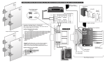
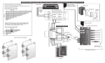
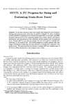
®
ussoun
TBL-75
Table-Top Volume Control
Instruction Manual
INTRODUCTION
The TBL-75 Volume Control is a free-standing stereo speaker-level volume control with
a front panel headphone jack and buitt-in impedance-matching options. It connects
between the speaker outputs of an amplifier or receiver and a pair of speakers. The
TBL-75 adjusts the volume of the speakers connected to it by adjusting the signal from
the amplifier to the speakers.
The TBL-75 is ideal for private listening as its tabletop design is suitable for placement
on a desk or bedside stand. When headphones are connected through the headphone
jack, it interrupts the speaker output, and the volume knob then controls the headphone
audio levels.
When using the TBL-75 in installations with more than one pair of speakers or with
additional volume controls, the TBL-75 has a rear panel impedance selector switch to
be set at 1X, 2X, 4X and ax. The 1X setting allows the volume control to be used as a
standard control. The 2X, 4X, and ax settings allow it to be used as an UltraMatch™
impedance matching volume control. The UltraMatch ™ volume control matches the
minimum output impedance of the amplifier or receiver, in addition to adjusting volume.
It eliminates the need for a speaker selector or additional impedance matching equipment.
PROPER SELECTOR SWITCH SETTING FOR IMPEDANCE MATCHING
By determining the drive capability of the amplifier with a few simple calculations, you
can determine the number of speakers the system can safely operate.
The selector switch must be set in a position that correctly multiplies the impedance of
the system to a level that is equal to or greater than the impedance of the amplifier.
The switch setting can be determined using the following simple steps:
1. Determine the amplifier1s minimum impedance. The amplifier's minimum impedance
is usually found following Wattage and Frequency Response in the amplifier's specification page of the manual. It may also be listed on the back panel of the amplifier
near the speaker terminals. The impedance value is expressed in ohms.
2. Identify the correct impedance-matching chart according to the amplifier's minimum
impedance. There are two impedance matching charts, one for a ohm amplifiers
and one for 4 ohm amplifiers. Choose the chart that describes your amplifier. If your
amplifier is 6 ohm stable, use the a ohm chart.
3. Determine the impedance for each pair of speakers by referring to its manual.
4. Determine the total number of 4 ohm pairs of speakers. (rows on charts) If using 6
ohm speakers, treat them as 4 ohm speakers
5. Determine the total number of 8 ohm pairs of speakers. (columns on charts)
2
6. Follow the appropriate row and column to determine selector switch settings.
7. Set the selector switch to the correct X setting as determined.
CONSIDERATIONS
1. Make sure that your amplifier has adequate wattage for the number of speakers.
Watts per channel divided by the number of pairs should equal or exceed the individual speaker's minimum wattage requirements.
2. It is recommended to use an UltraMatch™ volume control for each room.
3. Every jumper setting must be set on the same setting throughout the system.
4. A minimum speaker load of 4 ohms can be connected to the output of each
UltraMatch™ volume control.
Impedance Matching Charts For UItraMatch™
Impedance Matching For 4 Ohm Amplifiers
BOhm Pairs
0
°1 1X
-
2 2X
3 4X
4 4X
5 8X
6 8X
7 8X
8 8X
1
1X
2X
4X
4X
8X
8X
8X
8X
2
1X
2X
4X
4X
8X
8X
8X
8X
3
2X
4X
4X
8X
8X
8X
8X
4
2X
4X
4X
8X
8X
8X
8X
5
4X
4X
8X
8X
8X
8X
6
4X
4X
8X
8X
8X
8X
7
4X
8X
8X
8X
8X
8
4X
8X
8X
8X
8X
9
8X
8X
8X
8X
10
8X
8X
8X
8X
11
8X
8X
8X
12 13 14 15 16
8X 8X 8X 8X 8X
8X 8X 8X
8X
Impedance Matching For 8 Ohm Amplifiers
Example: The table to the right
shows an a ohm minimum impedance amplifier with 1 pair of 4 ohm
speakers and 3 pair of a ohm
speakers. The chart indicates the
jumper setting should be set at ax.
BOhm Pairs
_+-0""",+-""",,,-+_2__
_4,"",+_5........6""-+-__
7 -+--8-1
~
2X
. . .;.4,;. .;,.X+-8;;;.;...X~8X~8.....;.X..........,;;;.8X~
~
8X 8X 8X
~ ................
e _-+---f---+_+--.....I....----I
8X
.;:
°
o
~
......;;...~~;.......a....;....;....J
3
TYPE OF SPEAKER WIRE
For most applications, we recommend you use 16 or 18 gauge, stranded copper
speaker wire for the TBl-75 speaker connections. For wiring runs longer than 100 feet,
14 gauge wire is recommended. Using speaker wire larger than 14 gauge for TBl-75
Volume Controls is not recommended as the wire may not fit into the connectors.
NOTE - Never use solid-core, aluminum or Romex® type wire with volume controls.
When running speaker wires inside walls, most states and municipalities in the U.S.
specify that you must use a special type of speaker wire. Usually, the requirement is
that the wire has a specific "Cl" fire rating, such as "Cl-2" or "Cl-3". Consult your
Russound dealer, building contractor, or local building and inspection department if
unsure about which type of wire is best for your application. If you need speaker wire,
we recommend you order Russound AW series wire. The AW Series speaker cables
use multi-strand copper wire and high-temperature PVC jackets specially designed for
snaking through the walls and for long speaker runs.
OPTIONAL RUSSOUND COMPONENTS
The wiring diagram for the TBl-75 includes an ALTx and optional EZB-1 SC. The EZB1SC is recommended but not required for TBl-75 installation. The EZB-SC connecting
block is a neat, compact wiring device capable of connecting four volume controls to an
amplifierls outputs. The AlTx volume control is an in-wall stereo volume control.
WIRING INSTRUCTIONS
1. Connect the speaker leads from the amplifier's outputs to the connector labeled
Input on the TBl-75. The wires should stay consistent, left + of the amplifier to left +
Input of the TBl-75, observing polarity and identification.
CAUTION: Do not reverse the input and output connections on the TBl-75!!
2. Connect speaker wire from the TBl-75 Output connector to the speakers.
WIRING INSTRUCTIONS USING OPTIONAL EZB1-SC
1. Connect the speaker leads from the amplifier's outputs to the connector labeled
Input on the EZB-1 SC. The wires should stay consistent, left + of the amplifier to
left + Input of the EZB-1 SC, observing polarity and identification.
2. Connect speaker wire from the EZB-1 SC Output connector to the Input connector
on the TBl-75.
3. Connect speaker wire from the TBl-75 Output connectors to the speakers.
4
Speaker wire
~
.-/
TBL-75
/
~
+
~I
1=
~
I••
•
0,0
lfi "
I
0.01
q 'fl
Iii
SPr.-."':[111
~ ..~
I: •••• :1 :[3
I(C-:::,"~ ICE:
I
I
I
I
I
I
I
I Speaker wire
I
I
I
I
I
I
I
I~ : " II ~
~
ll"""':
@@ @@
\Iii.
.~ _1NP\Jl_
SPEM(P'
-~
=
lX:Jl:'X
:.~.I
2X
•
l+
4X
II
~
III
" iii
~. ~
l·
R·
R+
-"'", 1- ~
QII
e(:,i.)\ e
MADE IN CHINA
Speaker wire
~~ ~.
I
I
I
URussound
~
c1
e'~
all
~
~
&.
I
'--
I
e~
Speakers
I
o
I
L
-+L
o
IH-t~
Speaker wire
D
D
ALTx volume control
'----------i
Speakers
e··~'
.... r-"Oe--'r
'.-'
e-:=-\
;.6)':.
:--.,
~~
e'¥e
Speaker wire
Typical TBL-75 Configuration (optional connections for EZB-1SC)
5
OPERATION
1. Make sure the amplifier or receiver is OFF and set the volume to minimum.
2. Set the TBL-75 volume to maximum (fully clockwise).
3. Turn on the amplifier or receiver and select a music source, such as tuner or CD
player:
4. Slowly turn up the amplifier or receiver volume and set it to a comfortable (not maximum) listening level. Be careful not to overdrive your amplifier: If the sound becomes
muddy or distorted, you have reached the limit of your amplifier's volume capability
and should quickly reduce the volume to avoid damaging your speakers.
NOTE: 12 o'clock (50%) on most receivers is full volume. An amplifier that is being
driven beyond its potential will produce DIC voltage (clipping) which will not pass
through a transformer, resulting in improper signal transfer and possible damage to
volume control and amplifier.
5. Adjust the volume of the speakers to the desired listening level using the TBL-75.
6. You can turn off the speakers in each room by turning the knob on the TBL-75 completely counter-clockwise.
IMPORTANl: If you are unsure of any of the installation procedures, the products
should be installed by a professional custom installer:
SPECIFICATIONS
Power Handling:
# of steps:
Total Attenuation:
Frequency Response:
Impedance Multipliers:
Terminations:
Wire Size;
Dimensions:
Weight:
6
126 Wattslch. power handling, 42 watts/ch. RMS
12 steps, including "Off"
43db
20Hz - 20kHz, +1/-.5dB at rated power
1X, 2X, 4X and ax
Spring-loaded terminals
Up to 14 gauge wire
6.0W x 6.50 x 1.875H inches
(15.2 x 16.5 x 4.8 cm)
2.5 Ibs. (1.14kg)
WARRANTY
All Russound volume controls are fully guaranteed against all defects in materials and
workmanship as long as the original purchaser and user of the volume control owns
the unit. During the warranty period, Russound, at its option, will replace or repair any
defective part and correct any defect in workmanship without charge for parts or labor.
For this warranty to apply, the unit must be installed and used in accordance to its
written instructions. If necessary, repairs must be performed by Russound. The unit
must be returned to Russound at the owner's expense and with prior written permission of Russound. Accidental damage and shipping damage are not considered
defects, nor is damage resulting from abuse, or from servicing performed by an agent
or person not specifically authorized in writing by Russound. Damage to or destruction
of components due to application of excessive power voids the warranty on those
parts. Repairs to components damaged or destroyed due to application of excessive
power will be made by charging the owner the retail value of the parts and labor for
the repair.
To return items for repairs, the unit must be shipped to Russound at the owner's
expense, along with a written explanation of the nature of the service required. The unit
must be packed in a corrugated container with at least 3 inches of resilient material to
protect the unit from damage in transit. Russound reserves the right to request proof
of purchase. Except to the extent prohibited by applicable law, no other warranties,
whether expressed or implied, other than the express warranties stated herein, shall
apply to units sold to the purchaser. Russound shall not be liable for any implied warranty of merchantability or fitness for a particular purpose to any person other than the
original purchaser and user.
Russound sells products only through authorized Dealers and Distributors to ensure
that customers obtain proper support and service. Any Russound product purchased
from an authorized dealer or other source, including retailers, mail order sellers and
online sellers will not be honored or serviced under existing Russound warranty policy.
any sale of products by an unauthorized source or other manner not authorized by
Russound shall void the warranty on the applicable product.
All Russound TBl-75 volume controls conform to Ul Standard 1492 First Edition, and
for Canada Certified to CSA Standard 22.2 No. 1-M94. This certification assures that
your TEL-75 volume control has been designed and tested for safety.
l1Russou n ~_®
5 Forbes Rd. Newmarket, NH 03857
Tel 603.659.5170 • Fax 603.659.5388
e-mail: [email protected]
Rev. 1 06/1 0/04