1
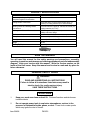
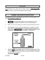
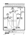
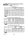
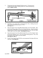
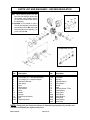
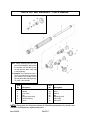
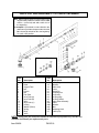
Owner’s Manual & Safety Instructions
Save This Manual Keep this manual for the safety warnings and precautions, assembly,
operating, inspection, maintenance and cleaning procedures. Write the product’s serial number in the
back of the manual near the assembly diagram (or month and year of purchase if product has no number).
Keep this manual and the receipt in a safe and dry place for future reference.
REV 15b
REV
HEAVY DUTY
OXYGEN /ACETYLENE WELDING KIT
Visit our website at: http://www.harborfreight.com
Email our technical support at: [email protected]
ITEM 92496
When unpacking, make sure that the product is intact
and undamaged. If any parts are missing or broken,
please call 1-888-866-5797 as soon as possible.
Copyright© 2003 by Harbor Freight Tools®. All rights reserved.
No portion of this manual or any artwork contained herein may be reproduced in
any shape or form without the express written consent of Harbor Freight Tools.
Diagrams within this manual may not be drawn proportionally. Due to continuing
improvements, actual product may differ slightly from the product described herein.
Tools required for assembly and service may not be included.
Read this material before using this product.
Failure to do so can result in serious injury.
SAVE THIS MANUAL.
PRODUCT SPECIFICATIONS
ITEM
DESCRIPTION
Torch Handle, Oxygen Regulator and
Acetylene Regulator Construction
Polished finish, all brass construction
Welding Nozzle and Heating Nozzle
Construction
Brass base with a Copper tip. VH-W2, #2 Nozzle (For
welding material 1/16”-1/8”)
Cutting Nozzle Construction
Welding Hose Size and Construction
Tip Cleaner Construction
Safety Glasses Construction
Brass and Steel. Chrome Plated oxygen lever. #1
Nozzle (For cutting material up to 3/4” thickness)
15 Ft. Long x 1/4” ID (each Hose)
Rubber and brass fittings
Steel files in an Anodized case
Plastic and Nylon, ANSI approved #10 Shade
Flint Lighter Construction
Chrome plated steel with a Flint tip
Welding Tip Replacement
Victor Style
Weight
19 Lbs.
Victor-Style Tip
SAVE THIS MANUAL
You will need this manual for the safety warnings and precautions, assembly,
operating, inspection, maintenance and cleaning procedures, parts list and assembly
diagram. Keep your invoice with this manual. Write the invoice number on the
inside of the front cover. Keep this manual and invoice in a safe and dry place for
future reference.
GENERAL SAFETY RULES
WARNING!
READ AND UNDERSTAND ALL INSTRUCTIONS
Failure to follow all instructions listed below may result in
electric shock, fire, and/or serious injury.
SAVE THESE INSTRUCTIONS
WORK AREA
1.
Keep your work area clean and well lit. Cluttered benches and dark areas invite accidents.
2.
Do not operate power tools in explosive atmospheres, such as in the
presence of flammable liquids, gases, or dust. Power tools create sparks which may ignite the dust or fumes.
Item 92496PAGE 2
3.
Keep bystanders, children, and visitors away while operating a power tool.
Distractions can cause you to lose control. Protect others in the work area from debris such as chips and sparks. Provide barriers or shields as needed.
PERSONAL SAFETY
4.
Stay alert. Watch what you are doing, and use common sense when operating a power tool. Do not use a power tool while tired or under the influence of drugs, alcohol, or medication. A moment of inattention while operating power tools may result in serious personal injury.
5.
Dress properly. Do not wear loose clothing or jewelry. Contain long hair. Keep your hair, clothing, and gloves away from moving parts. Loose clothes,
jewelry, or long hair can be caught in moving parts.
6.
Avoid accidental starting. Be sure the Power Switch is off before plugging
in. Carrying power tools with your finger on the Power Switch, or plugging in power
tools with the Power Switch on, invites accidents.
7.
Remove adjusting keys or wrenches before turning the power tool on. A
wrench or a key that is left attached to a rotating part of the power tool may result
in personal injury.
8.
Do not overreach. Keep proper footing and balance at all times. Proper footing
and balance enables better control of the power tool in unexpected situations.
9.
Use safety equipment. Always wear eye protection. Dust mask, non-skid safety
shoes, hard hat, or hearing protection must be used for appropriate conditions.
TOOL USE AND CARE
10.
Use clamps (not included) or other practical ways to secure and support the
workpiece to a stable platform. Holding the work by hand or against your body
is unstable and may lead to loss of control.
11.
Do not force the tool. Use the correct tool for your application. The correct
tool will do the job better and safer at the rate for which it is designed.
12.
Do not use the power tool if the Power Switch does not turn it on or off. Any tool that cannot be controlled with the Power Switch is dangerous and must
be replaced.
13.
Disconnect the Power Cord Plug from the power source before making any
adjustments, changing accessories, or storing the tool. Such preventive safety
measures reduce the risk of starting the tool accidentally.
Item 92496PAGE 3
TOOL USE AND CARE
14.
Store idle tools out of reach of children and other untrained persons. Tools
are dangerous in the hands of untrained users.
15.
Maintain tools with care. Keep cutting tools sharp and clean. Properly
maintained tools with a sharp cutting edge are less likely to bind and are easier to
control. Do not use a damaged tool. Tag damaged tools “Do not use” until repaired.
16.
Check for misalignment or binding of moving parts, breakage of parts, and
any other condition that may affect the tool’s operation. If damaged, have the
tool serviced before using. Many accidents are caused by poorly maintained tools.
17.
Use only accessories that are recommended by the manufacturer for your
model. Accessories that may be suitable for one tool may become hazardous when used on another tool.
SERVICE
18.
Tool service must be performed only by qualified repair personnel. Service or maintenance performed by unqualified personnel could result in a risk of injury.
19. When servicing a tool, use only identical replacement parts. Follow instructions in the “Inspection, Maintenance, And Cleaning” section of this manual. Use of unauthorized parts or failure to follow maintenance instructions may create a risk of electric shock or injury.
Item 92496PAGE 4
SPECIFIC SAFETY RULES
1.
Maintain labels and nameplates on the Heavy Duty Welding Kit. These carry
important information. If unreadable or missing, contact Harbor Freight Tools for
a replacement.
2.
Maintain a safe working environment. Keep the work area well lit. Make sure
there is adequate surrounding workspace. Always keep the work area free of
obstructions, grease, oil, trash, and other debris.
3.
Prevent eye injury and burns. Wearing and using personal safety clothing and
safety devices reduce the risk for injury. Wear ANSI approved welding goggles (such
as those included in this kit) featuring at least a number 10 shade lens rating. Leather
leggings, fire resistant shoes or boots should be worn when using this product. Do
not wear pants with cuffs, shirts with open pockets, or any clothing that can catch
and hold molten metal or sparks. Keep clothing free of grease, oil, solvents, or
any flammable substances. Wear dry, insulating gloves and protective clothing.
Wear an approved head covering to protect the head and neck. Use aprons, cape,
sleeves, shoulder covers, and bibs designed and approved for welding and cutting
procedures. When welding or cutting overhead or in confined spaces, wear flame
resistant ear plugs or ear muffs to keep sparks out of ears.
4.
Prevent accidental fires. Remove any combustible material from the work area.
When possible, move the work to a location well away from combustible materials.
If relocation is not possible, protect the combustibles with a cover made of fire
resistant material. Remove or make safe all combustible materials for a radius of
35 feet (10 meters) around the work area. Use a fire resistant material to cover
or block all open doorways, windows, cracks, and other openings. Enclose the
work area with portable fire resistant screens. Protect combustible walls, ceilings,
floors, etc., from sparks and heat with fire resistant covers. If working on a metal
wall, ceiling, etc., prevent ignition of combustibles on the other side by moving
the combustibles to a safe location. If relocation of combustibles is not possible,
designate someone to serve as a fire watch, equipped with a fire extinguisher, during
the welding process and for at least one half hour after the welding is completed.
Do not weld or cut on materials having a combustible coating or combustible internal
structure, as in walls or ceilings, without an approved method for eliminating the
hazard. Do not dispose of hot slag in containers holding combustible materials.
Keep a fire extinguisher nearby and know how to use it. After welding or cutting,
make a thorough examination for evidence of fire. Be aware that easily visible
smoke or flame may not be present for some time after the fire has started. Do
not weld or cut in atmospheres containing dangerously reactive or flammable
gases, vapors, liquids, and dust. Provide adequate ventilation in work areas to
prevent accumulation of flammable gases, vapors, and dust. Do not apply heat to
a container that has held an unknown substance or a combustible material whose
contents, when heated, can produce flammable or explosive vapors. Clean and
purge containers before applying heat. Vent closed containers, including castings,
before preheating, welding, or cutting.
Item 92496PAGE 5
5.
Avoid overexposure to fumes and gases. Always keep your head out of the
fumes. Do not breathe the fumes. Use enough ventilation or exhaust, or both, to
keep fumes and gases from your breathing zone and general area. Where ventilation
is questionable, have a qualified technician take an air sampling to determine the
need for corrective measures. Use mechanical ventilation to improve air quality.
If engineering controls are not feasible, use an approved respirator. Work in a
confined area only if it is well ventilated, or while wearing an air-supplied respirator.
Follow OSHA guidelines for Permissible Exposure Limits (PEL’s) for various fumes
and gases. Follow the American Conference of Governmental Industrial Hygienists
recommendations for Threshold Limit Values (TLV’s) for fumes and gases. Have
a recognized specialist in Industrial Hygiene or Environmental Services check the
operation and air quality and make recommendations for the specific welding or
cutting situation.
6.
Always keep the Welding Hoses (D1A, or D1B) away from moving parts on
the tool. Examine the Welding Hoses for cuts, burns, or worn areas before each
use. If any damaged areas are found, replace the Welding Hoses immediately.
7.
Read and understand all instructions and safety precautions as outlined in
the manufacturer’s manual for the material you will weld or cut.
Item 92496PAGE 6
8.
Proper cylinder care. Secure cylinders to a cart, wall, or post, to prevent them from falling. All cylinders should be used and stored in an upright position. Never drop or strike a cylinder. Do not use cylinders that have been dented. Cylinder caps should be used when moving or storing cylinders. Empty cylinders should be kept in specified areas and clearly marked “empty”.
9.
Never use oil or grease on any inlet connector, outlet connector, or cylinder valves.
10.
Always use reverse-flow check valves on the torch and regulator. This greatly reduces the possibility of mixing gases in the regulator or hose.
11.
Working pressure on the Acetylene Regulator should NEVER be set above 15 PSI.
12.
There must be TWO O-Rings (C24, C25) on the Connector (C23) end. The
absence of either O-Ring can lead to flashback within the Torch Handle or Cutting
Attachment.
13. For the Cutting Attachment, inspect the tapered seating surfaces on the Tip and in the Torch Head. Have a qualified technician resurface the seat area if it has dents, burrs, or is burned. A poor seating surface may result in backfire or flashback.
14. Backfire and flashback. When the flame goes out with a loud “pop”, it is called a backfire. Backfire can be caused by (1) operating the Torch at lower pressures than required for the Tip used, (2) touching the Tip against the workpiece, (3) overheating the Tip, or (4) an obstruction in the Tip. If backfire occurs, shut off the Torch Handle Valves (oxygen first) and after remedying the cause, relight the Torch. A flashback is a condition that results when the flame flashes back into the Torch and burns inside with a shrill hissing or squealing noise. If flashback occurs, close the Torch Handle Valves (oxygen first), IMMEDIATELY. Flashback generally indicates a problem that should be repaired. A clogged Tip, improper functioning of the Valves, or incorrect acetylene/oxygen pressure could lead to flashback. Make sure to find the cause before relighting the Torch.
15.
WARNING! This product, when used for welding, plasma cutting,
soldering, or similar applications, produces chemicals known to the State
of California to cause cancer and birth defects or other reproductive harm.
(California Health & Safety Code § 25249.5, et seq.)
16.
WARNING! The brass components of this product contain lead, a
chemical known to the State of California to cause cancer and birth defects
or other reproductive harm. (California Health & Safety Code § 25249.5,
et seq.)
Item 92496PAGE 7
UNPACKING
When unpacking, check to make sure all the parts shown on the Parts Lists on pages
15-19 are included. If any parts are missing or broken, please call Harbor Freight Tools at
the number shown on the cover of this manual as soon as possible.
ASSEMBLY AND OPERATING INSTRUCTIONS
For additional information regarding the parts listed in the following pages, refer
to the Parts Diagrams on pages 15-19.
1.
NOTE! The following instructions are for acetylene gas use only. Contact your gas supplier for instructions on the use of other fuel gases.
2.
Make sure to secure the cylinders (as noted in the Specific Safety Rules section).
3.
While standing to one side, “crack” each cylinder valve. “Cracking” is to quickly open and close the valve, allowing gas to escape and clearing the valve of any foreign material.
WARNING! If oil or grease is found, discontinue using
cylinder and immediately contact your supplier. (See Figure D.)
QUICKLY
OPEN/CLOSE
VALVE TO
“CRACK”
CYLINDER
VALVE
HANDLE
ACETYLENE
OR
OXYGEN
CYLINDER
(NOT INCLUDED)
FIGURE D
4.
Attach the GREEN Oxygen Regulator (parts A1-A20E) to the oxygen cylinder. Then,
attach the RED Acetylene Regulator (parts 1-19) to the acetylene cylinder. Make
sure they are tightened in the correct directions (normally, clockwise for oxygen and
counterclockwise for acetylene.)
(See Figure E, next page.)
Item 92496PAGE 8
5.
IMPORTANT! The Pressure Adjusting Screw (18) on the Acetylene Regulator and
the Pressure Adjusting Screw (A18) on the Oxygen Regulator should be opened
slightly by turning counterclockwise to relieve pressure on the Regulator diaphragms
before opening the cylinder valves. If this is not done, pressure from the cylinders
may damage the diaphragms and render the Regulators inoperable.
GREEN
OXYGEN
REGULATOR
(PARTS A1-A20E)
WELDING NOZZLE (D4),
OR CUTTING NOZZLE (D6)
CYLINDER
VALVE
RED
ACETYLENE
REGULATOR
(parts 1-19)
PRESSURE
ADJUSTING
SCREW
(18)
PRESSURE
ADJUSTING
SCREW
(A18)
CUTTING
ATTACHMENT
(PARTS C1-C27)
TORCH
HANDLE
(PARTS B1-B10)
CYLINDER
VALVE
GREEN
WELDING
HOSE
(D1B)
RED
WELDING
HOSE
(D1A)
ACETYLENE
CYLINDER
(NOT INCLUDED)
OXYGEN
CYLINDER
(NOT INCLUDED)
FIGURE E
6.
Connect the GREEN and RED Welding Hoses (D1A, or D1B) to the proper
connections on the Torch Handle (parts B1-B10).
WARNING! If any traces of oil or grease are found, do not use. Contact
Item 92496PAGE 9
REV
your gas supplier immediately. (See Figure F.)
TORCH HANDLE
(PARTS B1-B10)
FIGURE F
7.
GREEN (OX) WELDING HOSE
(D1A)
RED (AC) WELDING HOSE (D1B)
Connect the Cutting Attachment (parts C1-C27) to the Torch Handle (parts B1-B10).
Always check the Connector (C23) and Coupling Nut (C22) for damage or oil. If
either are found, discontinue use and contact your gas supplier.
WARNING!
Make sure the two O-Rings (C24, C25) are not damaged or
missing, otherwise gases will mix inside the Torch Handle
(parts B1-
B10) and result in flashback or backfires. (See
CUTTING ATTACHMENT (PARTS C1-C27)
CONNECTOR (C23)
COUPLING NUT (C22)
O-RING O-RING
(C24)
(C25)
FIGURE G
CUTTING ATTACHMENT (PARTS C1-C27)
FIGURE H
8.
TORCH HANDLE (PARTS B1B10)
GREEN (OXYGEN)
WELDING HOSE
(D1A)
RED (ACETYLENE)
WELDING HOSE
(D1B)
Check connections for leaks. Adjust the Acetylene Regulator (parts 1-19) and
Oxygen Regulator (parts A1-A20E) to their normal operating pressure. Use an
approved leak detection solution to check for leaks at the Welding Hoses (D1A,
and D1B) and cylinder valve connections. If leaks are found, tighten the nuts more
Item 92496PAGE 10
securely. If a leak still persists, discontinue use and call your gas supplier.
WARNING! NEVER set the Acetylene Regulator (parts 1-19) to a delivery
pressure above 15 PSI. (See Figures I, J, and K.)
WELDING TIP CHART
Metal Thickness
Tip Size
1/64” - 3/64”
1/32” - 5/64”
3/64” - 3/32”
1/16” - 1/8”
1/8” - 3/16”
3/16” - 1/4”
1/4” - 1/2”
00
0
1
2
3
4
5
Oxygen Pressure Acetylene Pressure
P.S.I.G.
P.S.I.G.
Min.
Max.
Min.
Max.
3
5
5
3
5
3
5
3
5
3
5
3
3
5
5
3
7
3
4
6
5
10
7
4
6
12
5
8
FIGURE I
OXY-ACETYLENE MULTI-FLAME HEATING CHART
Tip Size
6
8
Acetylene
Pressure
Range
P.S.I.G.
Oxygen
Pressure
Range
P.S.I.G.
4-6
8 - 12
Acetylene Cubic Oxygen Cubic
Feet Per Hour Feet Per Hour
Min.
Max.
Min.
Max.
8 - 11
14
40
15
44
10 - 18
30
80
33
88
FIGURE J
OXY-ACETYLENE CUTTING NOZZLE CHART
Oxygen
Pressure
P.S.I.G.
Metal Thickness Nozzle Size
Min.
Max.
Acetylene
Pressure
P.S.I.G.
Min.
Max.
1/2”
0
30
35
3
5
3/4”
1
30
35
33
5
FIGURE K
Item 92496PAGE 11
9.
To determine the proper Acetylene Regulator (parts 1-19) pressure and Oxygen Regulator (parts A1-A20E) pressure for neutral flame adjusting, refer to Figures I, and K.
HIGH PRESSURE LEVER
(C20)
PRE-HEAT OXYGEN CONTROL VALVE
(C26)
CUTTING
NOZZLE
FIGURE L
(D6)
10.
OXYGEN CONTROL VALVE
(B8 with OX Label (B9))
ACETYLENE CONTROL VALVE
(B8 with AC Label (B10))
Depending on use, attach either a Cutting Nozzle #1 (D6), or Welding Nozzle #2
(D4) to the Cutting Attachment (parts C1-C27).
(See Figure L.)
11.
Open the Oxygen Control Valve (B8 with label (B9)) on the Torch Handle. Open
the Pre-Heat Oxygen Valve (C26) on the Cutting Attachment. Adjust the Oxygen
Regulator (parts A1-A20E) to the desired working pressure. Then, close the Oxygen
Control Valve on the Torch Handle. (See Figures E, and L.)
12.
Open the Acetylene Control Valve (B8 with label (B10)) on the Torch Handle. Adjust
the Acetylene Regulator (parts 1-19) to the desired working pressure. Then, close
the Acetylene Control Valve on the Torch Handle.
(See Figures E, and L.)
13.
Hold the Torch Handle (parts B1-B10) in one hand and the Flint Lighter (D9) in the
other hand. (See Figure M.)
FIGURE M
FLINT LIGHTER (D9)
ACETYLENE
CONTROL
VALVE
(B8 with AC Label (B10))
Item 92496PAGE 12
14.
Open the Acetylene Control Valve (B8 with AC Label (B10)) about 1/4 turn, and
ignite the acetylene gas coming out of the Nozzle (part D4).
WARNING! Always point the Nozzle away from other people when
lighting. (See Figures L, and M.)
15. Slowly open the Acetylene Control Valve (B8 with AC Label (B10)) further until the
smoke subsides and the flame jumps away from the end of the Nozzle (part D4)
slightly. (See Figure M.)
16.
Slowly open the Oxygen Control Valve (B8 with OX Label (B9)) until a brilliant
neutral flame is reached. (If the flame has a smooth inner cone, the flame is called
neutral.) (See Figure N.)
17.
WARNING! Always use appropriate welding goggles or welding
helmet when welding or cutting (at least a #10 shade lens rating).
OXYGEN CONTROL VALVE
(B8 with OX Label (B9))
NOZZLE (PARTS D4)
ACETYLENE
CONTROL VALVE
(B8 with AC Label (B10))
FIGURE N
18.
Once the welding or cutting job is competed, turn off the Oxygen Control Valve (B8
with OX Label (B9)). Then, turn off the Acetylene Control Valve (B8 with AC Label
(B10)).
NOTE: Reversal of this procedure may cause damage to the Torch Handle
(parts B1-B10). (See Figure N.)
19.
Shut off both cylinder valves. (See Figure E.)
20.
Drain the gas from the Oxygen Regulator (parts A1-A20E) by opening the Oxygen
Control Valve (B8 with OX Label (B9)). Complete this Step on the acetylene side.
(See Figure N.)
21.
Release the pressure on the Acetylene and Oxygen Regulators by turning their
Pressure Adjusting Screws (18, A18) counterclockwise. (See Figure E.)
Item 92496PAGE 13
INSPECTION, MAINTENANCE, AND CLEANING
1.
WARNING! Make sure the Welding Kit is cool to the touch and
disconnected from its oxygen and acetylene cylinders before performing
any inspection, maintenance, or cleaning procedures.
2.
BEFORE EACH USE, inspect the general condition of the Welding Kit. Check for
loose screws, misalignment or binding of moving parts, cracked or broken parts,
damaged Welding Hoses (D1A, or D1B), and any other condition that may affect
its safe operation. If a problem occurs, have the problem corrected before further
use.
Do not use damaged equipment.
3.
PERIODICALLY, use the Tip Cleaner (D7) to clean out dirt and debris from the
Nozzle (parts D4). Make sure to use the correct size Tip Cleaner for each individual
Nozzle. (See Assy. Diagram E.)
4.
TO CLEAN, use a clean cloth. If necessary, a mild detergent may be used.
Do not immerse any part of the Welding Kit in liquid.
Do not use solvents or other flammable agents to clean the Welding Kit.
PLEASE READ THE FOLLOWING CAREFULLY
THE MANUFACTURER AND/OR DISTRIBUTOR HAS PROVIDED THE PARTS LIST AND
ASSEMBLY DIAGRAM IN THIS MANUAL AS A REFERENCE TOOL ONLY. NEITHER THE
MANUFACTURER OR DISTRIBUTOR MAKES ANY REPRESENTATION OR WARRANTY
OF ANY KIND TO THE BUYER THAT HE OR SHE IS QUALIFIED TO MAKE ANY REPAIRS
TO THE PRODUCT, OR THAT HE OR SHE IS QUALIFIED TO REPLACE ANY PARTS OF
THE PRODUCT. IN FACT, THE MANUFACTURER AND/OR DISTRIBUTOR EXPRESSLY
STATES THAT ALL REPAIRS AND PARTS REPLACEMENTS SHOULD BE UNDERTAKEN
BY CERTIFIED AND LICENSED TECHNICIANS, AND NOT BY THE BUYER. THE BUYER
ASSUMES ALL RISK AND LIABILITY ARISING OUT OF HIS OR HER REPAIRS TO THE
ORIGINAL PRODUCT OR REPLACEMENT PARTS THERETO, OR ARISING OUT OF
HIS OR HER INSTALLATION OF REPLACEMENT PARTS THERETO.
Item 92496PAGE 14
PARTS LIST AND DIAGRAM 1 - ACETYLENE REGULATOR
Note: When ordering parts from
this parts list and diagram
always take the number from
the No. column (on the left).
For example: If you wish to order a
Body for this regulator you’d
take the part number from
the No. column (1). So you’d
order part 1.
Components Of: #12
ItemItem
No.
DescriptionNo.
Description
1
Body12A
Nut
2
H.P. Gauge (2.1” x 400psi/2800kpa)
12B
Diaphragm Plate
3
L.P. Gauge (2.1” x 30psi/200kpa)
12C Diaphragm
4
Inlet Nut (CGA 510)
12D Centralizer
5
Inlet Spigot13
Slip Ring
6
Filter14
Adjusting Spring
7
Valve Spring15
Spring Button
8
Anti-Vibrator16
Bonnet
9
Valve17
Label
10
Nozzle18
Adjusting Screw “T” Bar
11
Plunger19
Outlet Adaptor
12
Diaphragm Assembly
NOTE: Some parts are listed and shown for illustration purposes only, and are not available
individually as replacement parts.
Item 92496PAGE 15
PARTS LIST AND DIAGRAM 2 - OXYGEN REGULATOR
Note: When ordering parts from this
parts list and diagram always take
the number from the No. column
(on the left) and add a suffix of A to
the beginning.
For example: If you wished to order a
Filter for this regulator you’d take the
part number from the No. column (6)
and add an A to the beginning. So
you’d order part A6.
Components Of: #12
Components Of: #20
ItemItem
No.
DescriptionNo.
Description
1
Body12C
Diaphragm
2
H.P. Gauge (2.1” x 4000psi/28000kpa)
12D Centralizer
3
L.P. Gauge (2.1” x 200psi/1400kpa)
13
Slip Ring
4
Inlet Nut (CGA 540)
14
Adjusting Spring
5
Inlet Spigot15
Spring Button
6
Filter16
Bonnet
7
Valve Spring17
Label
8
Anti-Vibrator18
Adjusting Screw “T” Bar
9
Valve19
Outlet Adaptor
10
Nozzle20
Safety Valve
11
Plunger20A
Safety Body
12
Diaphragm Assembly20B
Safety Rubber
12A
Nut20C
Safety Seat
12B
Diaphragm Plate20D
Safety Spring
20E
Safety Cap
NOTE: Some parts are listed and shown for illustration purposes only, and are not
available individually as replacement parts.
Item 92496PAGE 16
PARTS LIST AND DIAGRAM 3 - TORCH HANDLE
Components Of: #8
Note: When ordering parts from this
parts list and diagram always take
the number from the No. column
(on the left) and add a suffix of B
to the beginning.
For example: If you wished to order a
Tail for this handle you’d take the
part number from the No. column
(4) and add an B to the beginning.
So you’d order part B4.
ItemItem
No
DescriptionNo
Description
1
Torch Head8
Valve Stem Assembly
2
Handle8A
Valve
3
Inner Tube8B
Washer
4
Tail8C
Nut
5
Oxygen Valve Body
8D
Adjusting Knob
6
Gas Valve Body
9
Label (OX)
7
Cover10
Label (AC)
NOTE: Some parts are listed and shown for illustration purposes only, and are not
available individually as replacement parts.
Item 92496PAGE 17
PARTS LIST AND DIAGRAM 4 - CUTTING ATTACHMENT
Note: When ordering parts from this parts list and
diagram always take the number from the No.
column (on the left) and add a suffix of C to
the beginning.
For example: If you wished to order a Head for this
attachment you’d take the part number from the
No. column (2) and add an C to the beginning.
So you’d order part C2.
Components Of: #26
ItemItem
NoDescription NoDescription
1
Tip Nut17
HP Spring
2
Head18
Washer
3
Oxygen Tube19
Valve Cap
4
Nut20
Lever
5
Ferrule21
Sprial Pin
6
Nut22
Coupling Nut
7
Fuel Tube23
Connector
8
Inner Tube (A)
24
O-Ring (Big)
9
Inner Tube (B)
25
O-Ring (Small)
10
Spiro26
Valve Stem Assembly
11
Inner Tube (C)26A
Valve
12
O-Ring26B
Washer
13
Washer (Teflon)26C
Nut
14
Spring26D
Adjusting Knob
15
Body27
Label (OX)
16Valve
NOTE: Some parts are listed and shown for illustration purposes only, and are not
available individually as replacement parts.
Item 92496PAGE 18
PARTS LIST AND DIAGRAM 5 - ACCESSORY PARTS
Note: When ordering parts from this
parts list and diagram always take
the number from the No. column
(on the left) and add a suffix of D
to the beginning.
For example: If you wished to order
a Welding nozzle you’d take the
part number from the No. column
(4) and add an D to the beginning.
So you’d order part D4.
ItemItem
No
DescriptionNo
Description
1A
Green (OX) Welding Hose
8
Safety Glasses
1B
Red (AC) Welding Hose
9
Flint Lighter
4
Welding Nozzle (#2)
10
Oxygen Check Valve
6
Cutting Nozzle #1
11
Acetylene Check Valve
7
Tip Cleaner
NOTE: Some parts are listed and shown for illustration purposes only, and are not
available individually as replacement parts.
Item 92496PAGE 19
LIMITED 90 DAY WARRANTY
Harbor Freight Tools Co. makes every effort to assure that its products meet high
quality and durability standards, and warrants to the original purchaser that this product
is free from defects in materials and workmanship for the period of 90 days from the date
of purchase. This warranty does not apply to damage due directly or indirectly, to misuse,
abuse, negligence or accidents, repairs or alterations outside our facilities, criminal activity,
improper installation, normal wear and tear, or to lack of maintenance. We shall in no event
be liable for death, injuries to persons or property, or for incidental, contingent, special
or consequential damages arising from the use of our product. Some states do not allow
the exclusion or limitation of incidental or consequential damages, so the above limitation
of exclusion may not apply to you. THIS WARRANTY IS EXPRESSLY IN LIEU OF ALL
OTHER WARRANTIES, EXPRESS OR IMPLIED, INCLUDING THE WARRANTIES OF
MERCHANTABILITY AND FITNESS.
To take advantage of this warranty, the product or part must be returned to us with
transportation charges prepaid. Proof of purchase date and an explanation of the complaint
must accompany the merchandise. If our inspection verifies the defect, we will either
repair or replace the product at our election or we may elect to refund the purchase price
if we cannot readily and quickly provide you with a replacement. We will return repaired
products at our expense, but if we determine there is no defect, or that the defect resulted
from causes not within the scope of our warranty, then you must bear the cost of returning
the product.
This warranty gives you specific legal rights and you may also have other rights
which vary from state to state.
3491 Mission Oaks Blvd. • PO Box 6009 • Camarillo, CA 93011 • 1-888-866-5797
Item 92496PAGE 20