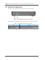
1
Ed.
00
OfficeServ 7030
Installation Manual
COPYRIGHT
This manual is proprietary to SAMSUNG Electronics Co., Ltd. and is protected by copyright.
No information contained herein may be copied, translated, transcribed or duplicated for any commercial
purposes or disclosed to the third party in any form without the prior written consent of SAMSUNG Electronics
Co., Ltd.
TRADEMARKS
is the trademark of SAMSUNG Electronics Co., Ltd.
Product names mentioned in this manual may be trademarks and/or registered trademarks of their respective
companies.
This manual should be read and used as a guideline for properly installing and operating the product.
This manual may be changed for the system improvement, standardization and other technical reasons without prior
notice.
If you need updated manuals or have any questions concerning the contents of the manuals, contact our Document
Center at the following address or Web site:
Address: Document Center 2nd Floor Jeong-bo-tong-sin-dong. Dong-Suwon P.O. Box 105, 416, Maetan-3dong
Yeongtong-gu, Suwon-si, Gyeonggi-do, Korea 442-600
Homepage: http://www.samsungdocs.com
© 2008 SAMSUNG Electronics Co., Ltd.
All rights reserved.
OfficeServ 7030 Installation Manual
INTRODUCTION
Purpose
OfficeServ 7030 is the most suitable system for small offices with 10 to 20 subscribers
circuit line. This manual describes the prerequisite for the installation of the OfficeServ
7030 system as well as how to install, inspect and operate the system.
Document Content and Organization
This document consists of 7 chapters and abbreviations as follows:
CHAPTER 1. Before Installing
This chapter describes the checklists (installation site, grounding & power conditions etc.)
which should be inspected before installing the OfficeServ 7030 system.
This chapter also describes the items included in the OfficeServ 7030 package and the
installation procedure.
CHAPTER 2. Mounting and Replacing the Boards
This chapter describes how to mount/replace various boards to/from the OfficeServ 7030
system.
CHAPTER 3. Installing the System
This chapter describes how to install an OfficeServ 7030 on the wall, if necessary,
depending on the installation environment.
CHAPTER 4. Connecting the Power
This chapter describes how to connect the power to the OfficeServ 7030 system.
CHAPTER 5. Connecting the C.O. Line
This chapter describes how to connect the C.O. lines to the OfficeServ 7030 system.
© SAMSUNG Electronics Co., Ltd.
I
Error! Use the Home tab to apply 제목 8,표준 제목 1 to the text that you want to appear here.
CHAPTER 6. Connecting the Stations and Additional Equipment
This chapter describes how to connect various stations and additional equipment
(analog/digital phones, door phones, door locks etc.) to the OfficeServ 7030 system.
CHAPTER 7. Starting the System
This chapter describes the items to check before starting the OfficeServ 7030 system, as
well as the procedure for starting the system and the procedure for testing whether the
system is operating normally after startup.
ABBREVIATION
Describes the abbreviations frequently used in this document.
Conventions
The following types of paragraphs contain special information that must be carefully read
and thoroughly understood. Such information may or may not be enclosed in a rectangular
box, separating it from the main text, but is always preceded by an icon and/or a bold title.
WARNING
Provides information or instructions that the reader should follow in order to avoid
personal injury or fatality.
CAUTION
Provides information or instructions that the reader should follow in order to avoid
a service failure or damage to the system.
CHECKPOINT
Provides the operator with checkpoints for stable system operation.
NOTE
Indicates additional information as a reference.
II
© SAMSUNG Electronics Co., Ltd.
OfficeServ 7030 Installation Manual
Reference
OfficeServ 7030 System Description
This manual introduces the OfficeServ 7030 and describes the system information
(hardware configuration, specification, functions etc.) necessary for this system.
OfficeServ 7030 Service Manual
This manual provides an overview, specification, hardware circuit configuration and
feature of the system.
OfficeServ 7030 Programming Manual
This manual describes how to use the MMC program to change the setting of the
OfficeServ 7030 system from the phone.
Revision History
EDITION
DATE OF ISSUE
REMARKS
00
04. 2008.
First Draft
© SAMSUNG Electronics Co., Ltd.
III
Error! Use the Home tab to apply 제목 8,표준 제목 1 to the text that you want to appear here.
This page is intentionally left blank.
IV
© SAMSUNG Electronics Co., Ltd.
OfficeServ 7030 Installation Manual
SAFETY CONCERNS
For product safety and correct operation, the following information must be given to the
operator/user and shall be read before the installation and operation.
Symbols
Caution
Indication of a general caution
Restriction
Indication for prohibiting an action for a product
Instruction
Indication for commanding a specifically required action
© SAMSUNG Electronics Co., Ltd.
V
Error! Use the Home tab to apply 제목 8,표준 제목 1 to the text that you want to appear here.
Warning
WARNING
Caution for grounding
- Do not connect the OfficeServ 7030 system's grounding wire to the building's
power conduit.
- The power and grounding installation should comply with the local standard;
all related works should be conducted according to the local standard.
- External grounding is required to prevent bodily injuries or system damages
from lightning, static electricity or voltage surge.
- Unplug the AC power cord before connecting the grounding wire. Failure to do
so may cause bodily injury.
- The OfficeServ 7030 system should be connected to a protective-ground
outlet.
- The GND in the back panel of the OfficeServ 7030 system should be grounded.
Using double-pole/neutral fusing
Do not attempt to repair the system after only removing the fuse from the neutral
line, Doing so may cause electric shock. If the repair is required, unplug the
system's power cord before proceeding.
AC power connection restriction
Connect the system’s AC power to a separated AC outlet. If the AC power is used
together with other equipments, a system failure or fire may occur due to static
electricity and/or voltage drop
Caution for power supply when mounting the board
Check if the cabinet power is turned off when mounting the board. Inserting or
removing a board while the power is turned on may damage the board.
Caution for the connection of the ground cable
Unplug the AC power cord before connecting the ground cable. Any attempt to
connect the ground cable while the power cord is connected may cause severe
bodily injury.
VI
© SAMSUNG Electronics Co., Ltd.
OfficeServ 7030 Installation Manual
Caution
CAUTION
Caution for installation
Only a trained service staff may install the OfficeServ 7030 system.
The equipment is intended to be installed only in a RESTRICTED ACCESS
LOCATION.
Leakage currents caused by ringing voltage–Grounding installation
instructions
1. A supplementary equipment grounding conductor should be installed between
the system and the earth in addition to the default equipment grounding
conductor provided in the power supply cord.
2. The size of the supplementary equipment grounding conductor should not be
smaller than the ungrounded branch-circuit supply conductors.
The supplementary equipment grounding conductor should be connected to
the product from the provided terminal, and connected to the earth in order to
maintain the earth connection when the power supply cord is unplugged.
The connection of the supplementary grounding conductor to the earth should
comply with the appropriate rules for terminating bonding jumpers, including
the National Electrical Code (Article 250, Part K), the ANSI/NFPA 70 and the
Canadian Electrical Code, C22.1 (Part 1, Article 10). The termination of the
supplementary grounding conductor may consist of building steel, of a metal
electrical raceway system or of any grounded item permanently and reliably
connected to the grounded electrical service equipment.
3. Bare, covered or insulated grounding conductors are acceptable. A covered or
insulated conductor must have a uniform outer finish, either green or green
with yellow stripes.
Separation of TNV and SELV-Pluggable A
The separate protective grounding terminal provided with this product should be
permanently connected to the earth. (Instruction)
Telephone line cord
To reduce the risk of fire, use only No. 26 AWG or larger (e.g., 24 AWG), UL
Listed or CSA Certified Telecommunication Line Cord.
© SAMSUNG Electronics Co., Ltd.
VII
Error! Use the Home tab to apply 제목 8,표준 제목 1 to the text that you want to appear here.
Prohibition of metal accessories
Do not wear metal accessories such as rings and watches to prevent electric
damages to the system.
AC power connection restriction
Do not share the AC power of the OfficeServ 7030 system or the AC power of the
external UPS with other devices.
Checking power-off
Check if the cabinet power is turned off when mounting the board. Inserting or
removing a board while the power is turned on may damage the board.
Board reset
New settings are applied only after the board is reset. The system may
malfunction if the board is not properly initialized.
Caution for Installation
Only a trained service staff may install the OfficeServ 7030 system.
VIII
© SAMSUNG Electronics Co., Ltd.
OfficeServ 7030 Installation Manual
TABLE OF CONTENTS
INTRODUCTION
I
Purpose .................................................................................................................................................. I
Document Content and Organization..................................................................................................... I
Conventions........................................................................................................................................... II
Reference ............................................................................................................................................. III
Revision History .................................................................................................................................... III
SAFETY CONCERNS
V
Symbols ................................................................................................................................................. V
Warning ................................................................................................................................................ VI
Caution ............................................................................................................................................... VII
CHAPTER 1. Before Installing
1.1
1-1
Site Information ..................................................................................................................... 1-1
1.1.1
Safety Conditions.................................................................................................................. 1-1
1.1.2
Temperature and Humidity Conditions ................................................................................. 1-1
1.2
Grounding Conditions ........................................................................................................... 1-2
1.3
Power Conditions .................................................................................................................. 1-2
1.4
Checking the Package ........................................................................................................... 1-3
1.5
Cabinet Configuration ........................................................................................................... 1-4
1.6
System Installation Procedure.............................................................................................. 1-6
CHAPTER 2. Mounting and Replacing the Boards
2-1
2.1 Connecting the Grounding Wire ............................................................................................... 2-1
2.2
2.1.1
Opening ................................................................................................................................ 2-1
2.1.2
Grounding ............................................................................................................................. 2-4
Mounting the Boards ............................................................................................................. 2-5
2.2.1
Removing Dummy Parts ...................................................................................................... 2-5
2.2.2
Setting Switches ................................................................................................................... 2-5
2.2.3
Mounting Optional Boards .................................................................................................... 2-7
© SAMSUNG Electronics Co., Ltd.
IX
Error! Use the Home tab to apply 제목 7,제목 7_목차 to the text that you want to appear here.
2.3
2.2.4
Mounting the daughter Boards ............................................................................................. 2-9
2.2.5
Closing/Cabling ................................................................................................................... 2-12
Replacing the Boards........................................................................................................... 2-14
CHAPTER 3. Installing the System
3.1
3.2
3-1
Installing on a Wall ................................................................................................................. 3-1
3.1.1
Required Tools ...................................................................................................................... 3-1
3.1.2
Installing on a Wall ................................................................................................................ 3-2
Connecting the Basic Cabinet to the Expansion Cabinet ................................................... 3-3
CHAPTER 4. Connecting thePower
4.1
4-1
Connecting the Power............................................................................................................ 4-1
4.1.1
Cautions when Connecting the Power ................................................................................. 4-1
4.1.2
Connecting the Power .......................................................................................................... 4-2
4.2
Connecting the External UPS ................................................................................................ 4-4
4.3
Connecting the Power Fail Transfer ..................................................................................... 4-5
CHAPTER 5. Connecting the C.O. Line
5-1
5.1
Line Conditions ...................................................................................................................... 5-1
5.2
Connecting the C.O. Line....................................................................................................... 5-2
5.2.1
Cautions When Connecting the C.O. Line ........................................................................... 5-2
5.2.2
Connecting Common C.O. Line ........................................................................................... 5-2
CHAPTER 6. Connecting the Stations and Additional Equipment
6.1
6.2
X
6-1
Connecting the Stations ........................................................................................................ 6-1
6.1.1
Cautions when Connecting the Stations .............................................................................. 6-1
6.1.2
Connecting Analog Phones .................................................................................................. 6-2
6.1.3
Connecting Digital Phones ................................................................................................... 6-3
6.1.4
Connecting IP Phones .......................................................................................................... 6-4
6.1.5
Connecting to a Door Phone and Door Lock ....................................................................... 6-5
6.1.6
Connecting a Wireless LAN Access Point............................................................................ 6-6
Connecting Additional Equipment ........................................................................................ 6-7
6.2.1
Connecting the MOH/BGM Equipment ................................................................................ 6-7
6.2.2
Connecting External/Additional Page Equipment ................................................................ 6-8
6.2.3
Connecting Common Bells ................................................................................................... 6-8
6.2.4
Modifying the System Setting ............................................................................................... 6-9
6.2.5
Connecting the SMDR ........................................................................................................ 6-15
© SAMSUNG Electronics Co., Ltd.
OfficeServ 7030 Installation Manual
6.2.6
Connecting Printers ............................................................................................................ 6-16
CHAPTER 7. Starting the System
7.1
7-1
Pre-Check ............................................................................................................................... 7-1
7.1.1
Environment .......................................................................................................................... 7-1
7.1.2
Safety Conditions.................................................................................................................. 7-2
7.2
Starting the System ............................................................................................................... 7-2
7.3
Numbering Extensions and C.O. Lines ................................................................................ 7-3
7.4
Checking the System's Operation ........................................................................................ 7-4
7.4.1
Station Call Function ............................................................................................................. 7-4
7.4.2
Station Camp-On Function ................................................................................................... 7-4
7.4.3
C.O. Line Call Function ........................................................................................................ 7-5
7.4.4
C.O. Line Camp-On Function ............................................................................................... 7-5
ABBREVIATION
I
2 ~ I ......................................................................................................................................................... I
L ~ U ...................................................................................................................................................... II
LIST OF FIGURES
Figure 1.1
Left Side View of the OfficeServ 7030 Cabinet ..................................................... 1-4
Figure 1.2 Top Side View of the OfficeServ 7030 Cabinet ..................................................... 1-5
Figure 1.3
Right Side View of the OfficeServ 7030 Cabinet ................................................... 1-6
Figure 2.1
Removing the cable duct cover (1) ........................................................................ 2-1
Figure 2.2
Removing the cable duct cover (2) ........................................................................ 2-2
Figure 2.3
Removing the cable duct cover (3) ........................................................................ 2-2
Figure 2.4
Removing the screws ............................................................................................ 2-2
Figure 2.5
Removing the top cover ........................................................................................ 2-3
Figure 2.6 Grounding ............................................................................................................. 2-4
Figure 2.7
Removing the dummy parts .................................................................................. 2-5
Figure 2.8 Setting the Base Board Switches .......................................................................... 2-6
Figure 2.9 Mounting a Modem Board on the Base Board ...................................................... 2-7
Figure 2.10
Mounting an EPM Board on the Base Board ....................................................... 2-7
Figure 2.11 Setting Switches on the EPM Board.................................................................... 2-8
Figure 2.12 Location of the Base Board Slots ........................................................................ 2-9
Figure 2.13
Mounting 2BM/4TM on the Base Board ............................................................ 2-10
Figure 2.14
Mounting 2DM/4DM/4SM/4LM on the Base Board............................................ 2-10
© SAMSUNG Electronics Co., Ltd.
XI
Error! Use the Home tab to apply 제목 7,제목 7_목차 to the text that you want to appear here.
Figure 2.15 Tightening screws to install the daughter boards ............................................... 2-11
Figure 2.16 Installing the top cover (1) .................................................................................. 2-12
Figure 2.17 Installing the top cover (2) .................................................................................. 2-12
Figure 2.18 Cabling ............................................................................................................... 2-12
Figure 2.19 Installing the duct cover (1) ................................................................................ 2-13
Figure 2.20 Installing the duct cover (2) ................................................................................ 2-13
Figure 2.21 Turning Off the Cabinet Power........................................................................... 2-14
Figure 2.22 Removing the boards ......................................................................................... 2-15
Figure 2.23 Replacing the daughter boards .......................................................................... 2-15
Figure 3.1
Required Tools for the Installation on a Wall ......................................................... 3-1
Figure 3.2 Installation on a Wall (1) ........................................................................................ 3-2
Figure 3.3 Installation on a Wall (2) ........................................................................................ 3-2
Figure 3.4 Installation on a Wall (3) ........................................................................................ 3-2
Figure 3.5 Installation on a Wall (4) ........................................................................................ 3-3
Figure 3.6 Verlängerungskabel ............................................................................................... 3-3
Figure 3.7
Connecting the basic cabinet to the expansion cabinet ......................................... 3-4
Figure 4.1
Connecting the Power (use of a cabinet) ............................................................... 4-2
Figure 4.2
Connecting the Power (using Power cable) ........................................................... 4-3
Figure 4.3
Connecting an External UPS ................................................................................. 4-4
Figure 4.4
Connecting the Power Fail Transfer....................................................................... 4-5
Figure 5.1 P1 (RJ-45) Port of the 4TM Board ......................................................................... 5-2
Figure 5.2 P2~P4 (RJ-45) Port of the 4TM Board ................................................................... 5-2
Figure 5.3
RJ-45 Port (T-Mode only) of the 2BM Board .......................................................... 5-3
Figure 6.1 P1 (RJ-45) Port of the SLT .................................................................................... 6-2
Figure 6.2 P2 (RJ-45) Port of the SLT .................................................................................... 6-2
Figure 6.3
RJ-45 Port of the 4SM Board ................................................................................. 6-3
Figure 6.4
RJ-45 Port of the 4DLM Board ............................................................................... 6-3
Figure 6.5 IP Phone Layout .................................................................................................... 6-4
Figure 6.6
RJ-45 Port of the Ethernet Connection Board ........................................................ 6-5
Figure 6.7
RJ-45 Port of the 4DM/2DM Boards (for Door Phone) ........................................... 6-5
Figure 6.8
Connecting MOH/BGM Sources ............................................................................ 6-7
Figure 6.9
Connecting External/Additional Page Equipment .................................................. 6-8
Figure 6.10 Connecting Common Bells .................................................................................. 6-8
Figure 6.11
Web Management Initial Screen ........................................................................ 6-14
Figure 6.12 Connecting the SMDR ....................................................................................... 6-15
Figure 6.13 Connecting Printers ........................................................................................... 6-16
XII
© SAMSUNG Electronics Co., Ltd.
OfficeServ 7030 Installation Manual
LIST OF TABLES
Table 1.1 Power Condition ..................................................................................................... 1-2
Table 1.2 Package Items ........................................................................................................ 1-3
Table 1.3 Parts located on the left panel of the cabinet .......................................................... 1-4
Table 1.4 Parts located on the top panel of the cabinet ......................................................... 1-5
Table 1.5 Parts located on the right panel of the cabinet ....................................................... 1-6
Table 2.1 Jumpers/Switches of the Base/EPM Board ............................................................ 2-5
Table 2.2 Base Board Switches ............................................................................................. 2-6
Table 2.3 EPM daughter board switches ................................................................................ 2-8
Table 2.4 Mountable Boards .................................................................................................. 2-9
Table 5.1 Line condition of the OfficeServ 7030 ..................................................................... 5-1
Table 6.1 Distance Between Stations and the System ........................................................... 6-1
Table 6.2 Specification for the Wireless LAN Connection ...................................................... 6-6
Table 6.3 Specification of the SMDR System ....................................................................... 6-15
© SAMSUNG Electronics Co., Ltd.
XIII
Error! Use the Home tab to apply 제목 7,제목 7_목차 to the text that you want to appear here.
This page is intentionally left blank.
XIV
© SAMSUNG Electronics Co., Ltd.
OfficeServ 7030 Installation Manual
CHAPTER 1. Before Installing
This chapter describes the checklists (installation site, grounding & power conditions etc.)
which should be inspected before installing the OfficeServ 7030 system. This chapter also
describes the items included in the OfficeServ 7030 package and the installation procedure.
1.1 Site Information
Select a site that satisfies the following safety, temperature and humidity conditions:
1.1.1 Safety Conditions
y
OfficeServ 7030 system should not be installed near materials that can cause fire, such
as explosive gas and inflammable objects.
y
OfficeServ 7030 system should not be installed near equipments that generate
electromagnetic waves, such as monitors or copying machines.
y
The installation location should be easily accessible for trunk line and extension line
deployment, for power and grounding wire connection, and for maintenance and repair.
y
OfficeServ 7030 system should not be installed in populated aisles/passageways or in
areas used for moving equipment.
y
Keep the area clean. Prevent the dust from damaging the cabinet's board-connecting
part.
y
Before installing the OfficeServ 7030 system, check items such as the electric wiring
status, grounding status, voltage and frequency.
1.1.2 Temperature and Humidity Conditions
y
The temperature and humidity conditions are as follows:
− Operation Temperature: 0~40°C
− Storage temperature: -10~50°C
− Humidity: 10~90%
y
Cool area protected from direct sunlight
y
Ventilators should be installed to remove dust.
© SAMSUNG Electronics Co., Ltd.
1-1
CHAPTER 1. Error! Use the Home tab to apply 제목 1,장 제목 1 to the text that you want to appear here.
1.2 Grounding Conditions
The following measures should be taken when grounding the OfficeServ 7030 system:
y
The grounding wire of the OfficeServ 7030 system should be grounded to the earth
using a proper material.
y
The flow electric current between the power outlet’s grounding wire and the system’s
metal surface should be satisfactory.
y
Any additional equipment’s grounding should be connected to the system’s grounding
through a single connection point.
Cautions for grounding
- Do not connect the OfficeServ 7030 system's grounding wire to the building's
power conduit.
- The power and grounding installation should comply with the local standard; all
related works should be conducted according to the local standard.
- External grounding is required to prevent bodily injuries or system damages
from lightning, static electricity or voltage surge.
- Unplug the AC power cord before connecting the ground cable. Failure to do so
may cause bodily injury.
- The OfficeServ 7030 system should be connected to a protective-ground outlet.
- The GND in the back panel of the OfficeServ 7030 system should be grounded.
1.3 Power Conditions
The Power Supply Unit (PSU) of the OfficeServ 7030 system receives an AC input power
and supplies an output power of -54 V, +5 V, and +12 V to the system cabinet.
The power condition is as follows:
Table 1.1 Power Condition
Power Supply
PSU
Standards
Input Power
AC 220
Output Power
- DC -54 V, 0.5 A
200~240 V
- DC +5 V, 3 A
- DC +12 V, 1.8 A
1-2
© SAMSUNG Electronics Co., Ltd.
OfficeServ 7030 Installation Manual
1.4 Checking the Package
The list of the items included in the OfficeServ 7030 package is as follows:
Table 1.2 Package Items
Item
Name
Quantity
Remark
Cabinet
Basic Cabinet
1
-
Cable
Power Cable
1
-
Guide
Wall Mount Template
1
-
Manual
Assembly drawing for cable duct cover
1
-
Guide
Open/closing Guide
Bushing
Wall mount Bushing
4
-
Screw
Wall mount Screw
4
-
Lug
Lug for connecting FGND
1
Template
UTP Cable Types
Two types of UTP cable are available: Straight-through UTP cable and Crossover
UTP cable. The Straight-through UTP cable is used to connect the OfficeServ
7030 system's 4LM module to another system.
© SAMSUNG Electronics Co., Ltd.
1-3
CHAPTER 1. Error! Use the Home tab to apply 제목 1,장 제목 1 to the text that you want to appear here.
1.5 Cabinet Configuration
The cabinet of the OfficeServ 7030 system has three slots to install the boards.
Figure 1.1 Left Side View of the OfficeServ 7030 Cabinet
The descriptions of each part located on the left of the cabinet are listed in the table below.
Table 1.3 Parts located on the left panel of the cabinet
Part
1-4
Function
Power Switch
Turns the power of the OfficeServ 7030 system on/off.
Power I/O Connector
Connector for the power cable connection
© SAMSUNG Electronics Co., Ltd.
OfficeServ 7030 Installation Manual
Figure 1.2
Top Side View of the OfficeServ 7030 Cabinet
The descriptions of each part located on the top of the cabinet are listed in the table below.
Table 1.4 Parts located on the top panel of the cabinet
Part
RUN LED
Function
Main CPU operation status
- Off: Idle
- On (Green): Booting
- Blink (Green): Normal Operation of the Program
- ON (Red): Clearing the Flash Memory (Database)
LAN LED
LAN operation status
- Off: Link and LAN port not connected
- On (Green): Link and LAN port connected
- Blink (Green): Tx/Rx of data through LAN port.
MEM LED
The LED turns on when the flash memory is accessed by the CPU.
BRI LED
The port status
- Off: Not used
- On: In use
© SAMSUNG Electronics Co., Ltd.
1-5
CHAPTER 1. Error! Use the Home tab to apply 제목 1,장 제목 1 to the text that you want to appear here.
Figure 1.3 Right Side View of the OfficeServ 7030 Cabinet
The descriptions of each part located on the right of the cabinet are listed in the table below.
Table 1.5 Parts located on the right panel of the cabinet
Part
Function
C.O 1-4
Trunk ports.
LAN
LAN port.
MISC
Ports that connect external audio devices, paging device, loud bell,
common bell, or door bell.
LINK1-3
Ports that connect the base cabinet with the expansion cabinet
EXT1-8
Station ports for subscribers (i.e analog phone, digital phone, LAN)
SLT1, 2
Station ports for analog phones.
Reset
Button for resetting the system.
1.6 System Installation Procedure
The system installation procedure is as follows:
1)
2)
3)
4)
5)
6)
7)
1-6
Open the cabinet
Ground to the ground lug in the basic cabinet.
Remove the cabinet's dummy parts to insert the daughter boards
Insert the daughter boards into the universal slots (slot 2, 3 and 4).
Install the cabinet on a wall, if necessary, depending on the installation environment
Connect and tie the cables with the cable ties.
Connect the AC 220 200~240 V input power.
© SAMSUNG Electronics Co., Ltd.
OfficeServ 7030 Installation Manual
CHAPTER 2. Mounting and Replacing
the Boards
This chapter describes how to mount/replace various boards to/from the OfficeServ 7030
system.
2.1 Connecting the Grounding Wire
This section describes how to open the cabinet and connect an external grounding wire to
the OfficeServ 7030 system
2.1.1 Opening
1)
Hold the cable duct cover and push upward as shown in the following picture.
Figure 2.1 Removing the cable duct cover (1)
© SAMSUNG Electronics Co., Ltd.
2-1
CHAPTER 2. Error! Use the Home tab to apply 제목 1,장 제목 1 to the text that you want to appear here.
2)
Push aside the cable duct cover from the main unit.
Figure 2.2 Removing the cable duct cover (2)
The following figure illustrates the separated cable duct cover.
Figure 2.3 Removing the cable duct cover (3)
3)
Remove the two screws.
Figure 2.4 Removing the screws
2-2
© SAMSUNG Electronics Co., Ltd.
OfficeServ 7030 Installation Manual
4)
Push and lift the top cover to open the case.
Figure 2.5 Removing the top cover
© SAMSUNG Electronics Co., Ltd.
2-3
CHAPTER 2. Error! Use the Home tab to apply 제목 1,장 제목 1 to the text that you want to appear here.
2.1.2 Grounding
External Grounding
External grounding is required to prevent bodily injuries or system damages from
lightning, static electricity or voltage surge. The OfficeServ 7030 system should
be grounded with an 18AWG or higher electric wire, or an electric wire with a
cross-sectional area of 0.8mm2. The nominal thread diameter of the screw should
be at least 3.5 mm; a UL Listed Lug Terminal should be used for the ring terminal.
Connect the grounding to the base board as shown in the figure below, Tighten the ground
cable to the base board with a screw.
Figure 2.6 Grounding
Checking external grounding
After installing the OfficeServ 7030 system, ensure that the GND in the inner side
of the system cabinet is connected to the external grounding for communication
before operating the system.
2-4
© SAMSUNG Electronics Co., Ltd.
OfficeServ 7030 Installation Manual
2.2 Mounting the Boards
This section describes how to set the base board switches and mount the optional boards.
2.2.1 Removing Dummy Parts
Depending on daughter boards, remove the cabinet's dummy parts with a nipper.
Figure 2.7 Removing the dummy parts
2.2.2 Setting Switches
The base board and EPM board that are equipped with switches relative to the user
requirements, system configuration and/or daughter boards are as follows:
Table 2.1 Jumpers/Switches of the Base/EPM Board
Board
Switch
Base
S1 (1~8)
EPM
S1 (1~2)
Description
Sets the country code and future use
Sets whether to use the 4LM daughter board and whether
to use the Expansion cabinet.
© SAMSUNG Electronics Co., Ltd.
2-5
CHAPTER 2. Error! Use the Home tab to apply 제목 1,장 제목 1 to the text that you want to appear here.
Setting switches on base board
The base board is equipped with switches relative to the user requirements and system
configuration. To set the switches and mount the boards, proceed as follows:
Set the base board's S1 switch from SW5 to SW8 to Off. SW1 to SW4 are set depending on
the user’s purpose.
S1
OFF
ON
Figure 2.8 Setting the Base Board Switches
Table 2.2 Base Board Switches
Switch
S1
Description
SW1~SW4
The pins set the system's country code.
SW5
Reserved for future use
SW6
IP address Setting : On : Default factory setting address
Off : User setting address
SW7~SW8
2-6
Reserved for future use
© SAMSUNG Electronics Co., Ltd.
OfficeServ 7030 Installation Manual
2.2.3 Mounting Optional Boards
When mounting the optional board, align the base board connectors to the optional board
(EPM or modem) connectors, and press the optional board firmly downward with two
hands
1)
Mount the modem board to the base board's P7 and P8 connectors.
Figure 2.9
Mounting a Modem Board on the Base Board
MODEM
2)
Mount the EPM board to the base board's P2 connector.
EPM
Figure 2.10 Mounting an EPM Board on the Base Board
© SAMSUNG Electronics Co., Ltd.
2-7
CHAPTER 2. Error! Use the Home tab to apply 제목 1,장 제목 1 to the text that you want to appear here.
3)
Set SW1 to SW2 following the user’s purpose. Tighten the screw. Tighten the screws
which fit within the grooves of the EPM boards.
S1
ON
OFF
Figure 2.11 Setting Switches on the EPM Board
Table 2.3 EPM daughter board switches
Switch
S1
Description
SW1
- ON: Master cabinet
- Off: Slave cabinet.
SW2
- ON: Standalone
- Off: Master and slave
2-8
© SAMSUNG Electronics Co., Ltd.
OfficeServ 7030 Installation Manual
2.2.4 Mounting the daughter Boards
The following daughter boards can be mounted on the slots according to the OfficeServ
7030 configuration.
Table 2.4 Mountable Boards
Part
Slot
Mountable Board
Trunk Part
Slot 4
4TM, 2BM
Subscriber Part
Slot 2 and Slot 3
4DM, 2DM, 4SM, 4LM
slot 3
slot 2
slot 4
Figure 2.12 Location of the Base Board Slots
The 4TM Module board does not support the Dial Pulse dialing, but it supports
the DTMF dialing.
Caution for the power supply when mounting the boards
Check if the cabinet power is turned off when mounting the board. Inserting or
removing a board while the power is turned on may damage the board or cause
fire.
© SAMSUNG Electronics Co., Ltd.
2-9
CHAPTER 2. Error! Use the Home tab to apply 제목 1,장 제목 1 to the text that you want to appear here.
1)
2BM or 4TM can be mounted to the base board's P3 connector.
Figure 2.13 Mounting 2BM/4TM on the Base Board
2)
2DM, 4DM, 4SM or 4LM can be mounted to the base board's P1 and P4 connector.
Figure 2.14 Mounting 2DM/4DM/4SM/4LM on the Base Board
2-10
© SAMSUNG Electronics Co., Ltd.
OfficeServ 7030 Installation Manual
3)
Tighten the screws which fit within the grooves of the daughter boards.
Figure 2.15 Tightening screws to install the daughter boards
© SAMSUNG Electronics Co., Ltd.
2-11
CHAPTER 2. Error! Use the Home tab to apply 제목 1,장 제목 1 to the text that you want to appear here.
2.2.5 Closing/Cabling
1)
Push and align the top cover to close the case.
Figure 2.16
2)
Tighten two screws to install the top cover.
Figure 2.17
3)
Installing the top cover (1)
Installing the top cover (2)
Fasten the cables to the cabinet with a cable tie.
Figure 2.18 Cabling
2-12
© SAMSUNG Electronics Co., Ltd.
OfficeServ 7030 Installation Manual
4)
Align and install the cable duct cover as follows.
Figure 2.19
5)
Installing the duct cover (1)
Hold the cable duct cover and push downward as shown in the following picture.
Figure 2.20
© SAMSUNG Electronics Co., Ltd.
Installing the duct cover (2)
2-13
CHAPTER 2. Error! Use the Home tab to apply 제목 1,장 제목 1 to the text that you want to appear here.
2.3 Replacing the Boards
If the OfficeServ 7030 system fails to operate normally due to an error on the power supply
board, base board or daughter board, replace the board with a new one.
Removing the Cables
Before replacing a daughter board, remove all cables connected to the board.
To replace a board mounted in the slot of a cabinet, proceed as follows:
1)
Turn off the power of the cabinet in which the board is mounted.
Figure 2.21 Turning Off the Cabinet Power
2)
2-14
Remove the cable duct cover and open the upper case. Refer to section ‘2.1.1
Opening’.
© SAMSUNG Electronics Co., Ltd.
OfficeServ 7030 Installation Manual
3)
Remove the screw and extract the board carefully.
Figure 2.22 Removing the boards
4)
Align the new board to the connector of the slot, and press the daughter boards firmly
downward with two hands. Tighten the screw.
Figure 2.23 Replacing the daughter boards
5)
Close the cabinet. Refer to section ‘2.2.5 Closing/Cabling’.
© SAMSUNG Electronics Co., Ltd.
2-15
CHAPTER 2. Error! Use the Home tab to apply 제목 1,장 제목 1 to the text that you want to appear here.
This page is intentionally left blank.
2-16
© SAMSUNG Electronics Co., Ltd.
OfficeServ 7030 Installation Manual
CHAPTER 3. Installing the System
This chapter describes how to install an OfficeServ 7030 on the wall, if necessary,
depending on the installation environment.
3.1 Installing on a Wall
This section describes how to install the OfficeServ 7030 cabinet on a wall.
3.1.1 Required Tools
y
Mid-sized Phillips screw driver
y
Electric drill
y
Hammer
y
Wall Mount Template
y
Four plastic Bushings
y
Four cross-type screws
Figure 3.1 Required Tools for the Installation on a Wall
© SAMSUNG Electronics Co., Ltd.
3-1
CHAPTER 3. Error! Use the Home tab to apply 제목 1,장 제목 1 to the text that you want to appear here.
3.1.2 Installing on a Wall
To install the OfficeServ 7030 cabinet with a wall mount template, proceed as follows:
1) Drill holes on the marked position of the Wall Mount Template. Drill holes with a
minimum of 33 mm depth and approx. 6 mm width to ease the insertion of the plastic
bushings.
Figure 3.2 Installation on a Wall (1)
2)
Fix plastic anchors into the drilled holes with a hammer.
Figure 3.3 Installation on a Wall (2)
3)
Align the screw holes of the wall-type bracket to the fixed plastic anchors' positions.
Insert the screws to each hole and tighten the screws with a Philips screw driver.
Figure 3.4 Installation on a Wall (3)
3-2
© SAMSUNG Electronics Co., Ltd.
OfficeServ 7030 Installation Manual
4)
Align the holes of the OfficeServ 7030 cabinet to the bracket screws, then pull down
the cabinet to completely fix on the wall.
Figure 3.5 Installation on a Wall (4)
3.2 Connecting the Basic Cabinet to the
Expansion Cabinet
If the OfficeServ 7030 system consists of a basic cabinet and an expansion cabinet, connect
the Base cabinet to the expansion cabinet using the extension cables to allow signal
transmissions between the base boards.
1)
Three extension cables are needed to connect the Basic cabinet to the expansion
cabinet.
Figure 3.6
2)
Verlängerungskabel
Extension cable
With an extension cable, connect the basic cabinet's ‘Link1’ port to the extension
cabinet's ‘Link1’ port.
© SAMSUNG Electronics Co., Ltd.
3-3
CHAPTER 3. Error! Use the Home tab to apply 제목 1,장 제목 1 to the text that you want to appear here.
3)
With another extension cable, connect the ‘Link2’ port to the ‘Link2’ port.
4)
With the third cable, connect the ‘Link3’ to the ‘Link3.
Figure 3.7 Connecting the basic cabinet to the expansion cabinet
3-4
© SAMSUNG Electronics Co., Ltd.
OfficeServ 7030 Installation Manual
CHAPTER 4. Connecting thePower
This chapter describes how to connect the power to the OfficeServ 7030 system and how to
connect the external UPS.
4.1 Connecting the Power
4.1.1 Cautions when Connecting the Power
When the input power is normally supplied, the AC current is supplied to the Power
Supply Unit (PSU). If the input power is interrupted, the system can be operated using the
external UPS.
When connecting the power to the OfficeServ 7030 system, pay attention to the following
criteria:
y
The system supports 220 200V~240 V AC power.
y
A single AC outlet should be used solely for the system’s AC power. Sharing the AC
power with other devices can cause static and/or voltage drop, resulting in system
malfunction or fire.
y
Use a stable power source that can supply continuous AC power; instantaneous power
failures may cause malfunctions.
© SAMSUNG Electronics Co., Ltd.
4-1
CHAPTER 4. Error! Use the Home tab to apply 제목 1,장 제목 1 to the text that you want to appear here.
4.1.2 Connecting the Power
Single cabinet configuration
Use the power cable provided with the OfficeServ 7030 system to connect the input power
terminal located on the right panel of the basic cabinet to a grounded outlet.
Figure 4.1 Connecting the Power (use of a cabinet)
4-2
© SAMSUNG Electronics Co., Ltd.
OfficeServ 7030 Installation Manual
Basic and Expansion Cabinet Configuration
Connect each input power cable of the cabinet to a grounded outlet.
Figure 4.2 Connecting the Power (using Power cable)
© SAMSUNG Electronics Co., Ltd.
4-3
CHAPTER 4. Error! Use the Home tab to apply 제목 1,장 제목 1 to the text that you want to appear here.
4.2 Connecting the External UPS
An external UPS is required to ensure stable operation of the OfficeServ 7030 system in
case of a power failure. The rated capacity of an external UPS is AC 220 200V~240 V per
cabinet. The UPS should be connected to each cabinet to guarantee safety.
A fuse (125 VAC, 5 A) should be installed between the battery's output terminal and the
cabinet's battery connector.
To connect an external UPS to the OfficeServ 7030 system, proceed as follows:
1)
Prepare the UPS provided with the product.
2)
Connect each cabinet.
Figure 4.3 Connecting an External UPS
4-4
© SAMSUNG Electronics Co., Ltd.
OfficeServ 7030 Installation Manual
4.3 Connecting the Power Fail Transfer
The 4TM and the Baseboards support the Power Fail Transfer function.
If the AC power fails while the UPS is not connected, connect a power fail transfer circuit
by connecting the C.O. lines to the extensions. If a pair of trunk lines (4TM) is connected
to Pin1 and Pin2 of the first port in the base board's SLI, the lines will be connected to a
phone through Pin 4 and 5 of the 4TM. During the power failure, emergency calls can be
available since the C.O. line is directly connected to the phone by the internal relay
operation.
Figure 4.4 Connecting the Power Fail Transfer
© SAMSUNG Electronics Co., Ltd.
4-5
CHAPTER 4. Error! Use the Home tab to apply 제목 1,장 제목 1 to the text that you want to appear here.
This page is intentionally left blank.
4-6
© SAMSUNG Electronics Co., Ltd.
OfficeServ 7030 Installation Manual
CHAPTER 5. Connecting the C.O.
Line
This chapter describes how to connect the C.O. line to the OfficeServ 7030 system after the
installation.
5.1 Line Conditions
When connecting the C.O. lines, pay attention to the following criteria:
y
Use an AWG #24 or AWG #26 cables.
y
When wiring the cables in humid areas, remove the moisture before wiring.
y
The cables should be handled carefully to prevent any distortions or damages.
y
The subscriber lines should be kept indoors if at all possible.
y
Do not cable the subscriber lines around any high-voltage power line.
The leak resistance of the C.O. line connected to the OfficeServ 7030 system is as follows:.
Table 5.1 Line condition of the OfficeServ 7030
Line Condition
Leak Resistance
Leak Resistance between Lines
20 kΩ or higher
Leak Resistance Between Grounds
20 kΩ or higher
© SAMSUNG Electronics Co., Ltd.
5-1
CHAPTER 5. Error! Use the Home tab to apply 제목 1,장 제목 1 to the text that you want to appear here.
5.2 Connecting the C.O. Line
This section describes how to connect a common C.O. line (4TM and 2BM)
5.2.1 Cautions When Connecting the C.O. Line
When connecting the C.O. line, pay attention to the following criteria to prevent bodily
injuries and system damages:
y
Do not connect the C.O. line in extreme weather conditions such as storm and
lightning.
y
Do not connect the C.O. line in humid areas.
5.2.2 Connecting Common C.O. Line
Use a pair of AWG #24 (or AWG #26) cable to connect a common C.O. line to the
terminal pin of a terminal box connected to the OfficeServ 7030 system equipped with a
4TM or 2BM board.
Connecting to the 4TM Board
P1 Port
(RJ-45)
Pin No.
1
2
3
4
5
6
7
8
Function
PFT
PFT
-
C.O TIP
C.O RING
-
-
-
TIP
RING
Figure 5.1 P1 (RJ-45) Port of the 4TM Board
P2 ~P4-Port
(RJ-45)
Pin No.
1
2
3
4
5
6
7
8
Function
-
-
-
C.O TIP
C.O RING
-
-
-
Figure 5.2 P2~P4 (RJ-45) Port of the 4TM Board
5-2
© SAMSUNG Electronics Co., Ltd.
OfficeServ 7030 Installation Manual
Connecting to the 2BM Board
P1, P2 Port
(RJ-45)
Pin No.
1
2
3
4
5
6
7
8
Function
-
-
TX +
RX +
RX -
TX -
-
-
Figure 5.3 RJ-45 Port (T-Mode only) of the 2BM Board
© SAMSUNG Electronics Co., Ltd.
5-3
CHAPTER 5. Error! Use the Home tab to apply 제목 1,장 제목 1 to the text that you want to appear here.
This page is intentionally left blank.
5-4
© SAMSUNG Electronics Co., Ltd.
OfficeServ 7030 Installation Manual
CHAPTER 6. Connecting the Stations
and Additional Equipment
This chapter describes how to connect various stations and additional equipment
(analog/digital phones, door phones, door locks etc.) to the OfficeServ 7030 system.
6.1 Connecting the Stations
6.1.1 Cautions when Connecting the Stations
When connecting the stations, pay attention to the following criteria:
y
Do not connect the stations in extreme weather conditions such as storm and lightning.
y
Do not connect the stations in humid areas.
y
Comply with the manual of the station as well as with this document when
reconnecting the stations or changing the connections.
y
Connect the stations with a pair of #24 AWG or #26 AWG cables.
The distances between the stations and the OfficeServ 7030 system are as follows:
Table 6.1 Distance Between Stations and the System
Installation Distance
Standards
Digital Phone
Maximum 400 m (AWG #24)
Analog Phone
Maximum 1 km (AWG #24)
Door Phone
Maximum 400 m (AWG #24)
SMT-R2000
Maximum 100 m (Ethernet cable)
© SAMSUNG Electronics Co., Ltd.
6-1
CHAPTER 6. Error! Use the Home tab to apply 제목 1,장 제목 1 to the text that you want to appear here.
6.1.2 Connecting Analog Phones
Connect an analog phone to the base board's SLT, or to the 4SM board mounted on the
OfficeServ 7030 system.
Connecting to the Base Board’s SLT
Connect an analog phone to the ports of the base board's SLT with a pair of AWG #24 or
AWG #26 cables.
P1 Port
(RJ-45)
Pin No.
1
2
3
4
5
6
7
8
Function
PFT
PFT
-
SLI
SLI
-
-
-
TIP
RING
TIP
RING
Figure 6.1 P1 (RJ-45) Port of the SLT
P2 Port
(RJ-45)
Pin No.
Function
1
2
3
4
5
6
7
8
-
SLI
SLI
-
-
-
TIP
RING
Figure 6.2 P2 (RJ-45) Port of the SLT
6-2
© SAMSUNG Electronics Co., Ltd.
OfficeServ 7030 Installation Manual
Connecting to the 4SM Board
Connect an analog phone to the port of the 4SM board with a pair of AWG #24 or AWG
#26 cables.
P1~ P4-Port
(RJ-45)
Pin No.
1
2
3
4
5
6
Function
-
-
-
SLI
SLI
-
TIP
RING
7
8
Figure 6.3 RJ-45 Port of the 4SM Board
6.1.3 Connecting Digital Phones
Connect a digital phone to the base board's 4DM.
Connecting to the 4DM Board
Connect a digital phone to the ports of the base board's 4DM with a pair of AWG #24 or
AWG #26 cables.
P1~ P4-Port
(RJ-45)
Pin No.
1
Function
2
3
4
5
6
7
8
-
DLI
DLI
-
-
-
TIP
RING
Figure 6.4 RJ-45 Port of the 4DLM Board
Maximum number of allowed DS-5012L phones
Up to one DS-5012L phone can be connected to each 4DM board of the
OfficeServ 7030 system. If more than one DS-5012L phone are connected to the
4DM board, the power supply for all digital phones connected to the same board
will be automatically blocked. Up to two DS-5012L phones can be connected to
the basic cabinet or the expansion cabinet.
© SAMSUNG Electronics Co., Ltd.
6-3
CHAPTER 6. Error! Use the Home tab to apply 제목 1,장 제목 1 to the text that you want to appear here.
6.1.4 Connecting IP Phones
An IP phone is a phone that provides calls through the Ethernet LAN. The interface
between a digital phone connected to the OfficeServ 7030 system and an IP phone
connected to the LAN is as follows. By default, the base board supports four MGI channels
which enables the use of the IP phones.
1)
2)
3)
4)
5)
The connection between a digital phone and an IP phone is established/released using
the IP address of the LAN connected to the OfficeServ 7030 system.
The digital phone connected to the OfficeServ 7030 system converts the analog voice
data to PCM voice data and transmits the data to the base board through the 4DM
board.
The PCM voice data is converted to packet data by the base board and transferred to
the IP phone.
ne.
The IP phone converts the packet voice data to analog voice signals and displays the
signals through a handset or speaker.
The Voice signals coming from the IP phone are converted to packet data and
transmitted to the base board in the same way. The base board converts the packet
voice data to PCM voice data and transmits the data to the digital phone through the
4DM board. The digital phone converts and sends the PCM voice data to analog data.
Configure the MMC setting to suit the system before use.
OfficeServ 7030
IP Telephone
Digital Telephone
Figure 6.5 IP Phone Layout
6-4
© SAMSUNG Electronics Co., Ltd.
OfficeServ 7030 Installation Manual
6.1.4.1 Connecting Boards to the Ethernet
4LM/LAN port of the base board can be connected to the Ethernet with an Ethernet cable.
y
4LM Board-Line Ports (P1~P4)
y
Base Board-LAN Port
P1~P4 Port
(RJ-45)
Pin No.
1
2
3
4
5
6
7
8
Function
Tx+
Tx-
Rx+
-
-
Rx-
-
-
Figure 6.6 RJ-45 Port of the Ethernet Connection Board
6.1.5 Connecting to a Door Phone and Door Lock
Connect a door phone and a door lock to the OfficeServ 7030 system with a Door Phone
Interface Module (DPIM). Connect a pair of #24 AWG or #26 AWG cables to the LINE
port of the DPIM and the ports of the OfficeServ 7030 system's 4DM board.
Connecting to the 4DM/2DM Boards
Pin No.
1
2
3
4
5
6
7
8
Function
-
-
-
DLI TIP
DLI
-
-
-
RING
Figure 6.7 RJ-45 Port of the 4DM/2DM Boards (for Door Phone)
1)
2)
Connect the Door port of the DPIM and the line port of the DOOR BOX.
When using an automatic door lock, connect the Lock port of the DPIM and the door
phone contact point to the door lock.
The door lock contact point is designed to control the low-voltage relay and is operated
with a 24 VDC, 100 mA current.
MMC
MMC 211 is used to assign call numbers to the door phones.
© SAMSUNG Electronics Co., Ltd.
6-5
CHAPTER 6. Error! Use the Home tab to apply 제목 1,장 제목 1 to the text that you want to appear here.
6.1.6 Connecting a Wireless LAN Access Point
The wireless LAN service offered by the OfficeServ 7030 system requires the following
equipment:
y
SMT-R2000: Wireless LAN Access Point (AP)
y
SMT-W5100: Wireless LAN IP phone
Table 6.2
Specification for the Wireless LAN Connection
Item
OfficeServ 7030 System (Basic Cabinet)
Maximum number of users
16
Number of simultaneous users
MMC845 setting
References
For information on how to install and use the SMT-R2000 and SMT-W5100, refer
to the ‘VoWLAN Administration Guide’.
Connect the 4LM board and the SMT-R2000 WAN port with a RJ-45 Ethernet cable
(maximum distance:100m). The SMT-R2000 can not get the power from the 4LM and does
need to be connected to an additional power source.
6-6
© SAMSUNG Electronics Co., Ltd.
OfficeServ 7030 Installation Manual
6.2 Connecting Additional Equipment
This section describes how to connect optional equipments (Music on Hold
(MOH)/Background Music (BGM) sources, external page devices, common bells etc.) to
the OfficeServ 7030 system.
6.2.1 Connecting the MOH/BGM Equipment
The OfficeServ 7030 system offers music while on hold.
The system provides internal tone/music and external music sources from the C.O. or
extension line music sources. The selection of internal/external music sources is performed
through the MMC 861. One external music source is provided while on hold; the external
music source is connected to the MISC port.
A pair of MOH/BGM source lines is connected to Pin4 and Pin5 of the base board’s MISC
port.
The user's MOH/BGM source
Figure 6.8 Connecting MOH/BGM Sources
MMC
Select music sources for the C.O. lines through the MMC 408; select music
sources for extensions through the MMC 308. To use the external music source,
select this option through the MMC 861 (default is internal).
© SAMSUNG Electronics Co., Ltd.
6-7
CHAPTER 6. Error! Use the Home tab to apply 제목 1,장 제목 1 to the text that you want to appear here.
6.2.2 Connecting External/Additional Page Equipment
Instead of an internal speaker, external broadcasting equipment (amps or speakers) and
additional equipment that can broadcast page/ring signals outside the building can be
connected to the OfficeServ 7030 system. Connect the external/additional page equipment
to the MISC port of the base board mounted on the OfficeServ 7030 system. The power
cord of the external/additional page equipment should be connected separately.
The OfficeServ 7030 system supports several channels for external broadcasting and one
dry contact. If a pair of External Page Equipment lines is connected to Pin3 and Pin6, the
Dry Contact 1 line is connected to Pin1 and Pin2, and the Dry Contact 2 line is connected
to Pin7 and Pin8 of the base board’s MISC port.
Dry Contact
(for Common bell)
External Page Equipment
Figure 6.9 Connecting External/Additional Page Equipment
Dry Contact
A Dry Contact is a switch that can establish or release a power/line connection of
an external equipment.
6.2.3 Connecting Common Bells
A Common Bell is a type of the ring. When a ring is received through an extension of a
group, all extensions of the given group also receive the ring.
To use the common bell, connect the common bell to the MISC port mounted on the
OfficeServ system. The OfficeServ 7030 system supports only one dry contact for the
common bell.
Dry contact
(For common
Figure 6.10 Connecting Common Bells
6-8
© SAMSUNG Electronics Co., Ltd.
OfficeServ 7030 Installation Manual
6.2.4 Connecting Installation Tool
The system maintenance software is installed on a PC for programming. The Installation
Tool is an application that provides various functions necessary for system maintenance.
You can use the Installation Tool when you need to install a new system component or
change a system component or modify the database.
Below are the specifications required for the PC for programming where the Installation
Tool is to be installed.
Table 7.5 Specifications for the PC for Programming
Item
PC
Modem
© SAMSUNG Electronics Co., Ltd.
Specification
CPU
Pentium III or faster
Main Memory
256 MBytes or more
HDD Drive
At least 30 MBytes of free space
OS
Microsoft Windows 98 or newer
1,200~115,200 baud rate
6-9
CHAPTER 6. Error! Use the Home tab to apply 제목 1,장 제목 1 to the text that you want to appear here.
6.2.4.1 Connecting a PC for Programming Using a LAN Port
You can connect a PC where the Installation Tool is installed to the OfficeServ 7030 system
using a LAN port. The Installation Tool allows you to manage the OfficeServ 7030 system
remotely. This section describes how to connect a PC for programming to the OfficeServ
7400 system and how to configure the software to use that PC.
If a LAN is configured in your company, connect it to the LAN port of the MCP board
Base board and the PC for programming to it. If no LAN is configured in your company,
connect the PC for programming to the LAN port of the 4LM/Base board.
OfficeServ 7030
LAN
Installation Tool
Figure 6.11 Connecting Installation Tool
Below are the steps for connecting a PC for programming to the system.
1)
Configure the network parameters using the MMC 830 program.
2)
Configure the Installation Tool parameters.
Below is the description of each of the steps mentioned above.
6-10
© SAMSUNG Electronics Co., Ltd.
OfficeServ 7030 Installation Manual
Configuring the network parameters using the MMC 830 program
This step configures the network parameters of the OfficeServ 7030 system.. Consult your
network administrator for the network parameter values.
1)
2)
3)
4)
Set the IP address of the OfficeServ 7030 system.
Set the subnet mask of the OfficeServ 7030 system.
Set the gateway IP address of the OfficeServ 7030 system.
Reset the board.
Resetting the Board
You have the reset to board to apply the new settings. If the board is not reset
correctly, it may cause product malfunction.
Configuring the Installation Tool parameters
1) Run the Installation Tool.
2) On the main screen of the Installation Tool, select [System] Æ [Link Control] or
click the Port Basic icon.
Figure 6.12 Installation Tool
3)
When the <Link Control> is displayed, enter the name of the system in the [Name]
field.
© SAMSUNG Electronics Co., Ltd.
6-11
CHAPTER 6. Error! Use the Home tab to apply 제목 1,장 제목 1 to the text that you want to appear here.
4)
If the Link Type is LAN, enter the IP address of the OfficeServ 7030 system in the
[IP Address] field.
If the Link Type is MODEM, enter the internal modem number of the OfficeServ 7030
system in the [Telephone] field.
올바른 Modem 접속을 위한 권고 사항
OfficeServ 7030 과 Modem 으로 접속하기 위해서는 반드시 아래에서 예시하는
회사의 외장형 모델중의 한가지를 사용해야 합니다.
U.S. Robotics ,
Hayes ,
Zoom
6-12
© SAMSUNG Electronics Co., Ltd.
OfficeServ 7030 Installation Manual
6.2.5 Connecting Web Management
The OfficeServ 7030 system is equipped with the Web Management web server, and
supports the remote access through the network. The system administrator can change the
system setting by accessing the Web Management with a browser.
This section describes how to access the OfficeServ 7030 system.
To use within an in-house network, connect LAN to the LAN port of the base board and try
accessing from a client PC.
Setting the Network parameter through the MMC830 program
Set the network parameter of the OfficeServ 7030 system. For the setting value of the
network parameter, contact the network administrator.
1)
2)
3)
4)
Set the IP address of the OfficeServ 7030 system.
Set the subnet mask of the OfficeServ 7030 system.
Set the gateway address of the OfficeServ 7030 system.
Reset the board.
Resetting the Board
To apply the new setting, the board must be reset.
© SAMSUNG Electronics Co., Ltd.
6-13
CHAPTER 6. Error! Use the Home tab to apply 제목 1,장 제목 1 to the text that you want to appear here.
Getting access to the Web Management from a client PC
1)
Execute your browser. (Internet Explorer 5.5 or higher)
2)
Access the Web Management through the LAN IP address.
Access address: https://[System LAN IP Address]
Figure 6.13 Web Management Initial Screen
3)
6-14
Enter your ID and password on the Web Management initial screen, and click the
[OK] button to log in.
© SAMSUNG Electronics Co., Ltd.
OfficeServ 7030 Installation Manual
6.2.6 Connecting the SMDR
The Station Message Detail Recording (SMDR) computer is used for recording call
information, calculating phone bills and/or displaying various analysis data based on the
call data provided by the system.
The SMDR computer can be connected via the LAN port of the 4LM board or the base
board built in the OfficeServ 7030 system.
The SMDR system specification is as follows:
Table 6.3 Specification of the SMDR System
Item
Specification
Platform
IBM PC
CPU
Pentium 586 or higher
Operating System
Windows 95/98 or later
Main Memory
32 MB or more
To use within the company's LAN network, connect LAN to the LAN port of the base
board, and connect a SMDR computer to the LAN.
OfficeServ 7030
LAN
SMDR
Figure 6.14 Connecting the SMDR
© SAMSUNG Electronics Co., Ltd.
6-15
CHAPTER 6. Error! Use the Home tab to apply 제목 1,장 제목 1 to the text that you want to appear here.
6.2.7 Connecting Printers
The OfficeServ 7030 system can be connected to printers. The system can print various call
information or event information created by the system in real time whenever an event
occurs.
To use within the company's LAN network, connect LAN to the LAN port of the base
board, and connect a printer to the LAN. If the 4LM is built in the base board, a printer can
be connected to the LAN port of the 4LM.
M.
OfficeServ 7030
LAN
Printer
Figure 6.15 Connecting Printers
MMC
After connecting a printer, execute the MMC 804 and enter the I/O port through
which the printer is connected.
6-16
© SAMSUNG Electronics Co., Ltd.
OfficeServ 7030 Installation Manual
CHAPTER 7. Starting the System
This chapter describes the items to check before starting the OfficeServ 7030 system, as
well as the procedure for starting the system and the procedure for testing whether the
system is operating normally after startup.
7.1 Pre-Check
This section describes the items to check before starting the OfficeServ 7030 system.
7.1.1 Environment
y
Temperature
Check if the room temperature is between 0°C and 40oC. If the room temperature is
above or below the operational temperature, install a heating/cooling device to
maintain the operational temperature.
y
Humidity
Check if the humidity of the room is between 10% and 90%. Take special caution
since the humidity affects the electric components and the connectors of the system.
y
Direct Sunlight and Dust
The room where the OfficeServ 7030 system is installed should be protected from
direct sunlight and should have ventilation systems to prevent the system from
malfunctioning due to dusts.
© SAMSUNG Electronics Co., Ltd.
7-1
CHAPTER 7. Error! Use the Home tab to apply 제목 1,장 제목 1 to the text that you want to appear here.
7.1.2 Safety Conditions
The building where the OfficeServ 7030 system is installed should have lightning rods and
groundings to protect the system from lightning and electric leakage.
y
Check if the OfficeServ 7030 system is not inclined and is in level position.
y
Do not place devices that may cause electromagnetic interference near the system.
y
Place a fire extinguisher near the system. Since spring coolers can seriously damage
the system, use extinguishers such as Halor 1301 and Carbon Dioxide.
y
Ensure that the input power of the OfficeServ 7030 system is AC 90-260 V. Do not
share the power with other electric devices, such as motors and compressors.
y
Check if the AC voltage switch of the PSU is properly set according to the voltage of
the input power. (90~260 200~240VAC)
y
Check if the grounding terminal on the rear panel of the system is properly connected
to the external grounding.
7.2 Starting the System
To start the OfficeServ 7030 system, proceed as follows:
1)
Check if the boards and cables are properly mounted and connected to the OfficeServ
7030 cabinet.
2) Turn on the power of the OfficeServ 7030 basic cabinet, and turn on the power of the
expansion cabinet.
3) Check the LEDs from the base boards mounted on the OfficeServ 7030 cabinet.
y The RUN LED of the base board turns green and the MEM LED flashes when the
system starts the booting process normally.
y Once the booting is completed, the RUN LED of the base board flashes green, and
the MEM LED stops flashing
4) The MEM LED of the base board flashes green when the Flash Memory is accessed.
7-2
© SAMSUNG Electronics Co., Ltd.
OfficeServ 7030 Installation Manual
7.3 Numbering Extensions and C.O. Lines
Once the OfficeServ 7030 system is booted, the base board verifies the boards mounted on
each slot and saves this information as the default configuration of the system.
The C.O. line numbers from 701 are sequentially assigned to the C.O. line board mounted
on Slot 4 of the basic cabinet, and the subsequent numbers are respectively assigned to the
expansion cabinet. This numbering process continues until the C.O. line numbers are
assigned to all C.O. lines
The extension numbers from 201 are sequentially assigned to the extension board mounted
on Slot 1 of the basic cabinet, and the subsequent numbers are respectively assigned to the
next extension board of the next slot. This numbering process continues until the extension
numbers are assigned to all extensions. However, only the numbers from 201 to 349 are
assigned when using 3 digits.
By default, the last firstport of the first 4DM board is assigned to the attendant group. All
C.O. lines will ring this attendant extension unless the default value is changed. Thus, a
phone with an LCD panel should be connected to the last port of the first 4DM board.
The numbers between 500~549 are assigned to an extension group.
The numbers of C.O. lines, extensions, or extension groups can be changed using the MMC
724 program.
© SAMSUNG Electronics Co., Ltd.
7-3
CHAPTER 7. Error! Use the Home tab to apply 제목 1,장 제목 1 to the text that you want to appear here.
7.4 Checking the System's Operation
After starting the OfficeServ 7030 system, check if the system is operating normally.
Check if the basic functions of the OfficeServ 7030 system (Station Call, Station Camp-On,
C.O. Line Call, C.O. Line Camp-On etc.) are properly executed.
7.4.1 Station Call Function
Follow the procedure below and check if the calls between the stations are enabled:
1)
Lift the handset of a station.
Verify the intercom dial tone.
2) Press an extension number.
Check if the dial tone stops.
3) Press all extension numbers.
Verify the ring back tone.
4) Once the recipient answers the call, check the call status.
5) Hang up the phone and call a busy station.
Verify the busy tone.
7.4.2 Station Camp-On Function
If a caller dials a number and the recipient is busy, this function automatically connects the
recipient and the caller right after the recipient hangs up the call.
Follow the procedure below and check the Station Camp-On function:
1)
2)
3)
4)
5)
6)
7-4
Lift the handset of the test phone and dial a busy station.
Verify the busy tone.
Upon checking the dial tone, press the hook flash button.
Check if the busy tone stops.
Press the reservation code.
Verify the confirmation tone.
Lift the handset of the test phone and dial a busy station.
Check if the test phone rings.
Lift the handset of the test phone.
Check if the ring stops. Confirm the ring-back tone.
Check if the other phone rings.
Lift the handset of the other phone.
Check if the other phone stops ringing, if the ring-back tone of the test phone stops,
and if the parties are normally connected.
© SAMSUNG Electronics Co., Ltd.
OfficeServ 7030 Installation Manual
7.4.3 C.O. Line Call Function
Follow the procedure below and check if the external calls are connected normally.
1)
2)
3)
4)
5)
Lift the handset of the test phone.
Verify the intercom dial tone.
Press the C.O. line call code.
Verify the C.O. line dial tone.
Check if an error tone is activated on the phones that do not support C.O. line calls.
Press an external number.
Verify the ring back tone.
Once the call is connected, check the call status.
7.4.4 C.O. Line Camp-On Function
If a caller presses a C.O. line code to make an external call and all C.O. lines are busy, this
function reserves a C.O. line and notifies the caller if the C.O. line becomes available.
Follow the procedure below and check the C.O. Line Camp-On function.
1)
2)
3)
4)
5)
6)
Lift the handset of the test phone and press a C.O. line code.
Verify the C.O. line dial tone.
Check if a busy tone rings when all C.O. lines are busy.
Upon verifying the busy tone, press the hook flash switch of the test phone.
Check if the busy tone stops.
Press the code number of the C.O. line Camp-On function.
Verify the confirmation tone.
Hang up the test phone and make the C.O. line idle.
Check if the test phone rings and if the C.O. line becomes busy.
Lift the handset of the test phone.
Check if the test phone stops ringing. Verify the intercom dial tone and the C.O. line
dial tone.
© SAMSUNG Electronics Co., Ltd.
7-5
CHAPTER 7. Error! Use the Home tab to apply 제목 1,장 제목 1 to the text that you want to appear here.
This page is intentionally left blank.
7-6
© SAMSUNG Electronics Co., Ltd.
OfficeServ 7030 Installation Manual
ABBREVIATION
2
2DM
2 port DLI Module
2BM
2 port BRI Module
4
4DM
4 port DLI Module
4LM
4 port LAN Module
4SM
4 port SLI Module
4TM
4 port Trunk Module
AC
Alternating Current
AFT
Automatic Function Test
AP
Access Point
AWG
American Wire Gauge
BGM
Background Music
DC
Direct Current
DLI
Digital Line Interface
DPIM
Door Phone Interface Module
DSL
Digital Subscriber Line
GND
Ground
IP
Internet Protocol
A
B
D
G
I
© SAMSUNG Electronics Co., Ltd.
I
Error! Use the Home tab to apply 제목 8,표준 제목 1 to the text that you want to appear here.
L
LAN
Local Area Network
LCD
Liquid Crystal Display
LED
Light Emitting Diode
MOH
Music on Hold
M
MGI
P
PCM
Pulse Code Modulation
PSU
Power Supply Unit
SLI
Single Line Interface
SMDR
Station Message Detail Recording
TEPRI2
T1E1PRI
TRK
Trunk
UTP
Unshielded Twisted Pair
UPS
Uninterruptible Power Supply
UTP
Unshielded Twisted Pair
S
T
U
II
© SAMSUNG Electronics Co., Ltd.
OfficeServ 7030
Installation Manual
©2008 Samsung Electronics Co., Ltd.
All rights reserved.
Information in this manual is proprietary to SAMSUNG
Electronics Co., Ltd.
No information contained here may be copied, translated,
transcribed or duplicated by any form without the prior written
consent of SAMSUNG.
Information in this manual is subject to change without notice.
Unit A1
Brookside Business Park, Greengate, Manchester, M24 1GS
U.K
Tel number: +44 (0) 161 655 1140
Fax number: +44 (0) 161 655 1191
Email: [email protected]