1
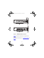
302403-B.mkr Page -1 Friday, January 15, 1999 2:56 PM
Installing Media
Dependent Adapters
(MDA)s
Part No. 302403-B Rev 00
January 1999
302403-B.mkr Page 0 Friday, January 15, 1999 2:56 PM
© 1999 by Bay Networks, Inc.
All rights reserved.
Trademarks
Bay Networks is a registered trademark and BayStack is a trademark of Bay
Networks, Inc. All other trademarks and registered trademarks are property of their
respective owners.
Statement of Conditions
In the interest of improving internal design, operational function, and/or reliability,
Bay Networks, Inc. reserves the right to make changes to the products described in
this document without notice.
Bay Networks, Inc. does not assume any liability that may occur due to the use or
application of the product(s) or circuit layout(s) described herein.
Federal Communications Commission (FCC) Compliance Notice:
Radio Frequency Notice
Note: This equipment has been tested and found to comply with the limits for a
Class A digital device, pursuant to Part 15 of the FCC rules. These limits are
designed to provide reasonable protection against harmful interference when the
equipment is operated in a commercial environment. This equipment generates,
uses, and can radiate radio frequency energy. If it is not installed and used in
accordance with the instruction manual, it may cause harmful interference to radio
communications. Operation of this equipment in a residential area is likely to cause
harmful interference, in which case users will be required to take whatever
measures may be necessary to correct the interference at their own expense.
EN 55 022 Declaration of Conformance
This is to certify that the Bay Networks 100BASE-FX/TX MDA are shielded
against the generation of radio interference in accordance with the application of
Council Directive 89/336/EEC, Article 4a. Conformity is declared by the
application of EN 55 022 Class A (CISPR 22).
Warning: This device is a Class A product. In a domestic environment, this product
may cause radio interference, in which case, the user may be required to take
appropriate measures.
These products conform to the provisions of Council Directive 89/336/EEC and 72/
23/EEC. The Declaration of Conformity is available on the Bay Networks World
Wide Web site at www.baynetworks.com.
302403-B.mkr Page 1 Friday, January 15, 1999 2:56 PM
Introduction
This document provides procedures for installing optional
plug-in media dependent adapters (MDAs) into supported
Bay Networks products equipped with an expansion slot.
The MDAs can support high-speed connections to servers,
shared Fast Ethernet hubs, or backbone devices.
Note: The MDAs are not hot-swappable. Power down
the switch before installing or removing an MDA.
The following MDA models are available:
Type
Model/Description
Refer to:
10BASE-T/
100BASE-TX
400-4TX MDA --- 4-port twisted pair
RJ-45 connectors.
page 2
100BASE-FX
(Fiber)
•
•
1000BASE-SX
(Shortwave
gigabit fiber)
•
•
400-2FX MDA --- 2-port
page 5
multimode fiber SC connectors.
400-4FX MDA --- 4-port
multimode fiber MT-RJ
connectors.
450-1SR MDA --- Single MAC
gigabit MDA with a separate
redundant PHY.
450-1SX MDA --- Single PHY
gigabit MDA.
page 10
(continued)
1
302403-B.mkr Page 2 Friday, January 15, 1999 2:56 PM
Type
Model/Description
Refer to:
1000BASE-LX
(Longwave
gigabit fiber)
•
page 13
•
450-1LR MDA --- Single MAC
gigabit MDA with a separate
redundant PHY.
450-1LX MDA --- Single PHY
gigabit MDA.
Bay Networks is constantly adding new models and
features to existing product lines; see your Bay Networks
sales representative for a full range of available MDAs.
For more details, see your switch product user’s guide.
The following Bay Networks products are supported:
•
BayStack 350 Series 10/100/1000 switches
•
BayStack 450 Series 10/100/1000 switches
For installation instructions, see “Installing an MDA” on
page 17.
10BASE-T/100BASE-TX MDA
The 400-4TX MDA (see Figure 1) uses four 10BASE-T/
100BASE-TX RJ-45 (8-pin modular) port connectors to
attach Ethernet devices.
Table 1 describes the 400-4TX MDA components and
LEDs.
2
302403-B.mkr Page 3 Friday, January 15, 1999 2:56 PM
1
2
100
10
F Dx
Activity
400-4TX MDA
5
4
3
BS45042A
Figure 1.
Table 1.
400-4TX MDA Front Panel
400-4TX MDA Components
Item
Label
Description
1
100
100BASE-TX port status LEDs (green):
On: The corresponding port is set to
operate at 100 Mb/s.
Off: The link connection is bad or there is
no connection to this port.
Blinking: The corresponding port is
management disabled.
(continued)
3
302403-B.mkr Page 4 Friday, January 15, 1999 2:56 PM
Table 1.
400-4TX MDA Components
(continued)
Item
Label
Description
2
10
10BASE-T port status LEDs (green):
On: The corresponding port is set to
operate at 10 Mb/s.
Off: The link connection is bad or there is
no connection to this port.
Blinking: The corresponding port is
management disabled.
3
F Dx
Full-duplex port status LEDs (green):
On: The corresponding port is in
full-duplex mode.
Off: The corresponding port is in
half-duplex mode.
4
Activity
Port activity LEDs (green):
Blinking: Indicates the network activity
level for the corresponding port. A high
level of network activity can cause LEDs
to appear to be on continuously.
5
10BASE-T/100BASE-TX RJ-45 (8-pin
modular) port connectors.
The RJ-45 ports are configured as media-dependent
interface-crossover (MDI-X) connectors. These ports
connect over straight cables to the network interface
controller (NIC) card in a node or server, similar to a
4
302403-B.mkr Page 5 Friday, January 15, 1999 2:56 PM
conventional Ethernet repeater hub. If you are connecting
to another Ethernet hub or Ethernet switch, you need a
crossover cable unless an MDI connection exists on the
associated port of the attached device.
The 400-4TX MDA can operate at either 10 Mb/s or
100 Mb/s. The speed is determined through
autonegotiation with its connecting device.
For installation instructions, see “Installing an MDA” on
page 17.
100BASE-FX MDAs
There are two 100BASE-FX models:
•
400-2FX MDA
The 400-2FX MDA uses two longwave 1300 nm SC
connectors to attach devices over 62.5/125 micron
multimode fiber optic cable.
•
400-4FX MDA
The 400-4FX MDA uses four longwave 1300 nm
MT-RJ connectors to attach devices over 62.5/125
micron multimode fiber optic cable.
Both models (see Figure 2) can be used to attach
fiber-based 100 Mb/s connections to other compatible Fast
Ethernet devices.
Single-mode fiber cable is not supported.
5
302403-B.mkr Page 6 Friday, January 15, 1999 2:56 PM
Warning: Fiber optic equipment can emit laser or
infrared light that can injure your eyes. Never look
into an optical fiber or connector port. Always assume
that fiber optic cables are connected to a light source.
Vorsicht: Glasfaserkomponenten können Laserlicht
bzw. Infrarotlicht abstrahlen, wodurch Ihre Augen
geschädigt werden können. Schauen Sie niemals in
einen Glasfaser-LWL oder ein Anschlußteil. Gehen
Sie stets davon aus, daß das Glasfaserkabel an eine
Lichtquelle angeschlossen ist.
Avertissement: L’équipement à fibre optique peut
émettre des rayons laser ou infrarouges qui risquent
d’entraîner des lésions oculaires. Ne jamais regarder
dans le port d’un connecteur ou d’un câble à fibre
optique. Toujours supposer que les câbles à fibre
optique sont raccordés à une source lumineuse.
6
302403-B.mkr Page 7 Friday, January 15, 1999 2:56 PM
Advertencia: Los equipos de fibra óptica pueden
emitir radiaciones de láser o infrarrojas que pueden
dañar los ojos. No mire nunca en el interior de una
fibra óptica ni de un puerto de conexión. Suponga
siempre que los cables de fibra óptica están
conectados a una fuente luminosa.
Avvertenza: Le apparecchiature a fibre ottiche
emettono raggi laser o infrarossi che possono risultare
dannosi per gli occhi. Non guardare mai direttamente
le fibre ottiche o le porte di collegamento. Tenere in
considerazione il fatto che i cavi a fibre ottiche sono
collegati a una sorgente luminosa.
7
302403-B.mkr Page 8 Friday, January 15, 1999 2:56 PM
1
100BASE-FX
2
100BASE-FX
Link
F Dx
Activity
TX
RX
TX
RX
400-2FX MDA
3
4
1
Link
2
F Dx
Activity
400-4FX MDA
3
4
BS45043A
Figure 2. 100BASE-FX MDA Front Panels
Table 2 describes the 100BASE-FX components and
LEDs.
For installation instructions, see “Installing an MDA” on
page 17.
8
302403-B.mkr Page 9 Friday, January 15, 1999 2:56 PM
Table 2.
100BASE-FX MDA Components
Item Label
Description
1
Communications link LEDs (green):
Link
On: Valid communications link
established.
Off: The communications link connection
is bad or there is no connection to this
port.
Blinking: The corresponding port is
management disabled.
2
F Dx
Full-duplex port status LEDs (green):
On: The corresponding port is in
full-duplex mode.
Off: The corresponding port is in
half-duplex mode.
3
Activity
Port activity LEDs (green):
Blinking: Indicates the network activity
level for the corresponding port. A high
level of network activity can cause LEDs
to appear to be on continuously.
4
100BASE-FX port connectors:
• Model 400-2FX uses SC connectors.
• Model 400-4FX uses MT-RJ connectors.
9
302403-B.mkr Page 10 Friday, January 15, 1999 2:56 PM
1000BASE-SX MDAs
Warning: This is a Class 1 Laser/LED product. It
contains a laser light source that can injure your eyes.
Never look into an optical fiber or connector port.
Always assume that the fiber optic cable or connector
is connected to a laser light source.
There are two 1000BASE-SX (shortwave gigabit) MDA
models:
•
The 450-1SR MDA is a single MAC MDA with a
separate redundant Phy (backup Phy port). Only one
Phy port can be active at any time. If the active Phy
port fails, the redundant Phy port automatically
becomes the active port.
•
The 450-1SX MDA is a single PHY MDA.
Both models (Figure 3) use shortwave 850 nm fiber optic
connectors to connect devices over multimode (550 meter)
fiber optic cable.
10
302403-B.mkr Page 11 Friday, January 15, 1999 2:56 PM
1
450-1SR MDA
(1-port redundant)
1000BASE-SX
2
1000BASE-SX
Link
Phy Select
Activity
TX
RX
TX
RX
450-1SR MDA
3
4
1
450-1SX MDA
(single port)
2
1000BASE-SX
Link
Phy
Activity
TX
RX
450-1SX MDA
3
4
BS45044A
Figure 3. 1000BASE-SX MDA Front Panels
Table 3 describes the 1000BASE-SX components and
LEDs.
For installation instructions, see “Installing an MDA” on
page 17.
11
302403-B.mkr Page 12 Friday, January 15, 1999 2:56 PM
Table 3.
1000BASE-SX MDA Components
Item Label
Description
1
Communication link LEDs (green):
Link
On: Valid communications link.
Off: The communications link
connection is bad or there is no
connection to this port.
Blinking: The corresponding port is
management disabled.
2
Phy
Phy status LEDs (green):
(or)
Phy Select
On: The corresponding Phy port is
active.
Off: The corresponding Phy port is in
backup mode or there is no connection
to this port.
3
Activity
Port activity LEDs (green):
Blinking: Indicates network activity
level for the corresponding port. A high
level of network activity can cause
LEDs to appear to be on continuously.
4
1000BASE-FX SC port connectors.
12
302403-B.mkr Page 13 Friday, January 15, 1999 2:56 PM
1000BASE-LX MDAs
Warning: This is a Class 1 Laser/LED product. It
contains a laser light source that can injure your eyes.
Never look into an optical fiber or connector port.
Always assume that the fiber optic cable or connector
is connected to a laser light source.
There are two 1000BASE-LX (longwave gigabit) MDA
models:
•
The 450-1LR MDA is a single MAC MDA with a
separate redundant Phy (backup Phy port). Only one
Phy port can be active at any time. If the active Phy
port fails, the redundant Phy port automatically
becomes the active port.
•
The 450-1LX MDA is a single Phy MDA.
Both models (Figure 4) use longwave 1300 nm fiber optic
connectors to connect devices over single mode
(3 kilometer) or multimode (550 meters) fiber optic cable.
Note: The optical performance of this transceiver
cannot be guaranteed when connected to a multimode
fiber plant without the use of the special offset SMF/
MMF mode conditioning patch cord (see
“1000BASE-LX Multimode Applications” on page
16).
13
302403-B.mkr Page 14 Friday, January 15, 1999 2:56 PM
1
450-1LR MDA
(1-port redundant)
1000BASE-LX
2
1000BASE-LX
Link
Phy Select
Activity
TX
RX
TX
RX
450-1LR MDA
3
4
1
450-1LX MDA
(single port)
2
1000BASE-LX
Link
Phy
Activity
TX
RX
450-1LX MDA
3
4
BS45045A
Figure 4. 1000BASE-LX MDA Front Panels
Table 4 describes the 1000BASE-LX MDA components
and LEDs.
For installation instructions, see “Installing an MDA” on
page 17.
14
302403-B.mkr Page 15 Friday, January 15, 1999 2:56 PM
Table 4.
1000BASE-LX MDA Components
Item Label
Description
1
Communication link LEDs (green):
Link
On: Valid communications link.
Off: The communications link
connection is bad or there is no
connection to this port.
Blinking: The corresponding port is
management disabled.
2
PHY
Phy status LEDs (green):
(or)
Phy Select
On: The corresponding Phy port is
active.
Off: The corresponding Phy port is in
backup mode or there is no connection
to this port.
3
Activity
Port activity LEDs (green):
Blinking: Indicates network activity
level for the corresponding port. A high
level of network activity can cause
LEDs to appear to be on continuously.
4
1000BASE-FX SC port connectors.
15
302403-B.mkr Page 16 Friday, January 15, 1999 2:56 PM
1000BASE-LX Multimode Applications
For 1000BASE-LX multimode applications, the longwave
gigabit transceivers must be mode conditioned externally
via a special offset SMF/MMF patch cord. The offset
SMF/MMF patch cord allows the same transceiver to be
used for both multimode and single-mode fiber. See your
Bay Networks sales representative for more information
about the SMF/MMF patch cord.
The 1000BASE-LX transceiver is designed to
mechanically accomodate the single-mode ferrules used
on one end of the special offset SMF/MMF patch cord.
Multimode ferrules must not be used because they can
bind and cause damage to the transceiver. Do not connect
multimode cables directly into the 1000BASE-LX MDA
transceiver. Instead, connect a special offset SMF/MMF
patch cord into the transceiver, and then connect the
multimode cable into the SMF/MMF patch cord.
For more information about gigabit transmission over fiber
optic cable and mode conditioning, refer to the following
publication:
Reference Note: Gigabit Ethernet Physical Layer
Considerations (Bay Networks part number 201540-B)
The publication is available on the World Wide Web at
support.baynetworks.com/library/tpubs/
At the Web site, click on Accelar under the Routing
Switches heading.
16
302403-B.mkr Page 17 Friday, January 15, 1999 2:56 PM
Installing an MDA
The Uplink Module slot on the BayStack 450 switches
accommodates a single MDA. The connection can be
either an RJ-45 10/100BASE-TX MDA or a fiber
(100BASE-FX or 1000BASE-SX/LX) MDA with an SC
or MT-RJ connector.
Note: The MDA is not hot-swappable. Power down
the switch before installing or removing an MDA.
To install an MDA into the Uplink Module slot, follow
these steps:
1.
Unplug the AC power cord from the back of the
switch.
2.
Loosen the thumb screws and remove the filler
panel (or previously installed MDA) from the
Uplink Module slot.
Note: If you are replacing an installed MDA with
another type of MDA, see “Replacing an MDA with a
Different Model” on page 19.
17
302403-B.mkr Page 18 Friday, January 15, 1999 2:56 PM
3.
Insert the MDA into the chassis slot (see Figure 5)
taking care to slide the MDA onto the guides
provided on the chassis.
Caution: Make sure the MDA slides in on the guides
provided. Failure to align the guides could result in
bent and broken pins
BS45046B
Figure 5. Installing an MDA
4.
Press the MDA firmly into the chassis slot. Be sure
that the MDA is fully seated into the mating
connector.
5.
Secure the MDA in the chassis by tightening the
thumb screws on the MDA front panel.
6.
Attach devices to the MDA ports (refer to the
Using the BayStack 450 Switch.
18
302403-B.mkr Page 19 Friday, January 15, 1999 2:56 PM
After connecting the port cables, continue to follow the
instructions in that manual to connect power and verify the
installation.
Note: The IEEE 802.3u specification requires that all
ports operating at 100 Mb/s use only Category 5
unshielded twisted pair (UTP) cabling.
Replacing an MDA with a Different Model
When replacing an installed MDA with another type of
MDA, complete the following steps to clear the switch
NVRAM:
1.
Power down the switch.
Remove the AC power cord from the power source.
2.
Remove the installed MDA.
Loosen the thumbscrews and remove the MDA.
3.
Cycle the switch power.
Power up the switch and wait for the Bay Networks
logo screen to appear (approximately 10 seconds);
then power down the switch.
4.
Install the replacement MDA.
Be sure to firmly tighten the two thumbscrews on the
MDA front panel.
5.
Power up the switch.
19