1
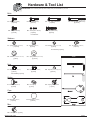
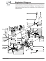
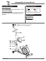
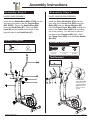
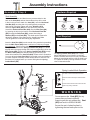
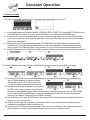
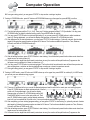
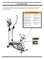
BRM 3671 /3681/3690
For use under U.S. Patent numbers 6159132, D459773, D438264
* This item is for consumer use only and it is not meant for commercial use.
OW N E R ’ S M A N UA L
This page intentionally left blank
General Information
Safety
Before you undertake any exercise program,
please be sure to consult with your doctor.
Frequent strenuous exercise should be
approved by your doctor and proper use
of your product is essential. Excessive or incorrect
training may result to health injuries. Please read
this manual carefully before commencing the
assembly of your product or starting to exercise.
• Please keep all children away from this item
when in use. Do not allow children to climb or
play on them when they are not in use.
• Supervise teenagers while they use this unit.
• For your own safety, always ensure that there
is at least 3 feet of free space in all directions
around your product while you are exercising.
• Regularly check to see that all nuts, bolts and
fittings are securely tightened. Periodically
check all moving parts for obvious signs of
wear or damage.
• Any adjustment devices that could interfere with
the user's movement on this unit should not be
left projecting.
• Clean only with a damp cloth, do not use
solvent cleaners. If you are in any doubt, do
not use your product; contact CUSTOMER
SUPPORT.
• Before use, always ensure that your product
is positioned on a solid, flat surface. If
necessary, use a rubber mat underneath to
reduce the possibility of slipping.
• Always wear appropriate clothing and
footwear such as training shoes when
exercising. Do not wear loose clothing that
could become caught in moving parts during
exercise.
• Do not use this unit if it is not functioning
properly or if it is not fully assembled.
• Do not use this unit for commercial purposes.
This unit is for home use only.
• Before use, you must read and understand all
instructions & warnings stated in this Owner’s
Manual as well as posted on the equipment.
• It is the facility owner’s responsibility to properly
instruct users on the proper operation of the
equipment and to warn them of the potential
hazards.
• If at any time during exercise you feel faint, dizzy
or experience pain, stop and consult your
physician.
Assembling Tools
- Ruler with both metric and English measurements
- 2 x Adjustable Wrenches
- 1 x Philips (”Crosshead”) Screw Driver
Weight Limit
Your product is suitable for users weighing:
250 pounds or less.
BRM3671/3681/3690
Storage and Use
Your product is intended for use in clean
dry conditions. You should avoid storage in
excessively cold or damp places as this may
lead to corrosion and other related problems.
Warranty
Body Flex Sports warrants your product for
a period of 1 year for the frame and 90 days
on all parts if the item is used for the intended
purpose, properly maintained and not used
commercially. Any alterations or incorrect
assembly of the product will void this warranty.
Proof of purchase must be presented for any
warranty validation (no exceptions). This
warranty applies to the original purchaser only
and is not transferable.
This warranty does not cover abuse or defects
caused during use, storage or assembly.
During the warranty period, Body Flex Sports
reserves the right to:
a). provide replacement parts to the
purchaser in an effort to repair the item.
b). repair the product returned to our
warehouse (at the purchaser’s cost).
c). replace the product if neither of the two
previously mentioned actions effect repair.
This warranty does not cover normal wear and
tear on upholstery.
Questions
If you have any questions concerning the
assembly of your item or if any parts are
missing, please DO NOT RETURN THE
ITEM TO THE STORE OR CONTACT THE
RETAILER. Our dedicated customer service
staff can help you with any questions you may
have regarding the assembly of this unit and
can also mail you replacement parts.
Customer Support
Customer Support is open 9:00 a.m. to 5:00
p.m. (Pacific Time) Monday through Friday.
Please contact us by any of the following
means.
Body Flex Sports, Inc.
21717 Ferrero Parkway, Walnut, CA 91789
Telephone: (888) 266 - 6789
Fax: (909) 598 - 6707
Email: info@bodyflexsports.com
Page 1
Hardware & Tool List
The following hardware is used to assemble your unit. Please take a moment to familiarize yourself with these items.
PLEASE NOTE: some of these parts may have already been pre-assembled on your unit.
Bolts
#2. Bolt (M8 x 15 mm)
[2 pieces]
#38. Bolt (M8x20 mm)
[4 pieces]
#12. Bolt (M8x45 mm)
[4 pieces]
#18. Left / Right Pedal Bolt
[2 pieces]
#63. Screw (M4 x 10 mm)
[4 pieces]
#65. Bolt (M8x30 mm)
[2 pieces]
#27. Carriage Bolt (M8x73 mm)
[4 pieces]
Pre-assemble
Washers
#4. Spring Washer (for M8 bolt)
[4 pieces]
#5. Washer (for M8 bolt)
[2 pieces]
#73. Washer (for M8 bolt,T1.5 mm)
[7 pieces]
#37. Arc-Washer (for M8 bolt)
[8 pieces]
Pre-assemble [3 pieces]
#42. Washer (for M10 bolt, T2.0 mm)
[1 piece]
Tools
#47. Spring Washer (for bolt #18)
[2 pieces]
Nuts
#72 Nylon Nut (for M 8 bolt)
[7 pieces]
#46. Nylon Nut (for bolt #18)
[2 pieces]
#49. Cap Nut (for M8 carriage bolt)
[4 pieces]
#43. Knob (M10)
[1 piece]
#39. Spring Loaded Knob
[1 piece]
Pre-assemble [3 pieces]
Knobs
#7. Knob Bolt (M8x36 mm)
[2 pieces]
Caps
#3. Bolt Cap (for M8 bolt)
[4 pieces]
#45. Bolt Cap (for bolt #18)
[2 pieces]
Misc.
#66. Clamp Cover [1 piece]
BRM3671/3681/3690
Page 2
Parts Listing
The following parts list describes all of the parts illustrated on the
exploded diagram on the following page. Please note, most of
these parts are already pre-assembled on your unit.
Part #
Description
1......................Handle Bar Foam Grip
Part #
Description
37....................Arc-Washer (for M8 bolt)
2......................Bolt (M8 x 15 mm)
38....................Bolt (M8x20 mm)
3......................Bolt Cap (for M8 bolt)
39....................Spring Loaded Knob
4......................Spring Washer (for M8 bolt)
41....................U Bracket
5......................Washer (for M8 bolt)
42....................Washer (for M10 bolt, 2.0 mm Thick)
6......................Bushing for Coupler Bar
43....................Knob (M10)
7......................Knob Bolt (M8x36 mm)
44....................Seat Post Sleeve
8......................L/R Coupler Bar
45....................Bolt Cap (for bolt #18)
9......................Nylon Nut (for M10 bolt)
46....................Nylon Nut (for bolt #18)
10....................Bolt Cap (for M10 bolt)
47....................Spring Washer (for bolt #18)
11. ...................Bushing
48....................Main Frame
12....................Bolt (M8x45 mm)
49....................Cap Nut (for M8 carriage bolt)
13....................Pedal
51....................Computer
52....................Main Sensor Wire (Upper)
14....................Pedal Tube
15....................Washer (for M10 bolt)
17....................Bolt (M10x50 mm)
53....................Pulse Sensor Wire (Upper)
54....................Main Sensor Wire (middle)
18L..................Left Pedal Bolt
58....................Center Post
18R. ................Right Pedal Bolt
59....................End Cap (round 25 mm)
19....................Bushing for Pedal Connection Joint
60....................Pulse Handle Bar Foam Grip
20....................Pedal Connection Joint
61....................Pulse Sensor
22....................End Cap (rectangular 25x40 mm)
62....................Screw
25....................Adjustable End Cap for Rear Stabilizer
63....................Screw (M4 x 10mm)
26....................Rear Stabilizer
64....................Pulse Sensor Wire (Lower)
27....................Carriage Bolt (M8x73 mm)
65....................Bolt (M8x30 mm)
28....................End Cap (round 28mm)
66....................Clamp Cover
29L/29R...........Handle Bar
67....................Main Sensor Wire (lower)
30....................Handle Bar Sleeve
68....................End Cap for Front Stabilizer
31....................Spacer
32....................Bolt (M10x55 mm)
33....................Seat
69....................Front Stabilizer
34....................End Plug (square 38mm)
72....................Nylon Nut (for M8 bolt)
73....................Washer (for M8 bolt)
35....................Horizontal Seat Bar
70....................Pulse Handle Bar
71....................AC Adapter
36....................Seat Post
BRM3671/3681/3690 BRM 3670 Stride Cycle
Page 3
Page ?
Exploded Diagram
The following diagram is provided to help you familiarize yourself with the parts and
hardware that will be used during the assembly process. Please note that not all of the
parts and hardware you see here will be used while you are assembling the machine
because some of these items are already pre-installed. Please continue to the next
page to begin the assembly process and use this page only as a reference guide for
parts and hardware.
BRM3671/3681/3690
Page 4
Assembly Instructions
Assembly Step 1
Hardware Required
FRONT STABILIZER ASSEMBLY
Secure the Front Stabilizer (#69) to the Main Frame
(#48) using a total of two Carriage Bolts (#27)
two Arc-Washers (#37) and two Cap Nuts (#49).
#27. Carriage Bolt (M8x73 mm)
[4 pieces]
#37. Arc-Washer
[4 pieces]
REAR STABILIZER ASSEMBLY
Secure the Rear Stabilizer (#26) to the Main Frame
(#48) using a total of two Carriage Bolts (#27)
two Arc-Washers (#37) and two Cap Nuts (#49).
#49. Cap Nut
[4 pieces]
Tool Required
Make sure this wire is hanging out before proceeding
to the next step. If it has fallen inside the tube, use a
bent wire to “fish” it out.
BRM3671/3681/3690
Page 5
Assembly Instructions
Hardware Required
Assembly Step 2
WIRE CONNECTIONS
Connect the Main Sensor Wire [middle] (#54) to the Main
Sensor Wire [lower] (#67).
#38. Bolt (M8x20 mm)
[4 pieces]
CENTER POST ASSEMBLY
Slide the Center Post (#58) onto the Main Frame (#48) and
secure it using a total of four Arc-Washers (#37) and four
Bolts (#38).
#37. Arc-Washer
[4 pieces]
Tools Required
55
40
1
2
3
55
Make sure this wire is hanging out before
assembling the Center post (#58).
40
BRM3671/3681/3690
1
2
3
4
Page 6
4
Assembly Instructions
Assembly Step 3
Coupler Bar Assembly
Slide two Spacers (#31) onto the two bars that are protruding from the Center Post (#58). Then slide
one Left Pedal Bolt (#18L) into the Pedal Connection Joint (#20). Assemble the Coupler Bar (#8L) to
the left side of the unit by sliding the upper part onto the left bar that is protruding from the Center Post
(#58). Secure it using one Washer (#5), one Spring Washer (#4), one Bolt (#2) and then place a Bolt
Cap (#3) on top of the Bolt (#2). Lift the lower segment of the Coupler Bar (#8L) and align the Pedal
Connection Joint (#20) to the hole on the pedal crank. Push the Left Pedal Bolt (#18L) through the
hole on the pedal crank and secure it using one Spring Washer (#47), the Nylon Nut (#46) with black inner ring,
and then place a Bolt Cap (#45) on top of the Nylon Nut (#46). Repeat this process on the opposite side.
PLEASE NOTE:
a):Turn COUNTERCLOCKWISE to tighten the Left Pedal Bolt (#18L) and CLOCKWISE to tighten Nylon Nut (#46) with BLACK inner nylon ring.
b):Turn CLOCKWISE to tighten the Right Pedal Bolt (#18R) and COUNTERCLOCKWISE to tighten Nylon Nut (#46) with WHITE inner nylon ring.
Hardware Required
#2. Bolt (M8 x 15 mm)
[2 pieces]
#4. Spring Washer
[2 pieces]
#18. Left / Right Pedal Bolt
[2 pieces]
#47. Spring Washer
[2 pieces]
BRM3671/3681/3690
Tools Required
LEFT SIDE
RIGHT SIDE
#5. Washer
[2 pieces]
#3. Bolt Cap
[2 pieces]
#46. Nylon Nut (for bolt #18)
[2 pieces]
#45. Bolt Cap
[2 pieces]
Note: Keep the Left/Right Pedal Bolt
(#18L/18R) perfectly straight as they
go through the Left/Right Pedal
Connection Joint (#20) and the
Crank . If the Left/Right Pedal Bolt
(#18L/18R) are connected to the Crank
incorrectly, damage to the Left/Right
Pedal Bolt (#18L/18R) and Crank will
occur.
Page 7
Assembly Instructions
Assembly Step 4
Assembly Step 5
HANDLE BAR ASSEMBLY
PULSE HANDLE BAR ASSEMBLY
Insert the two Handle Bars (#29L & 29R) into the
openings at the end of the two Coupler Bars
(#8L & #8R). Secure the Handle Bars (#29)
using two Knob Bolts (#7). Place two Bolt
Caps (#3) on the welded nuts located on the
opposite side of the Knob Bolts (#7).
Install the Pulse Handle Bar (#70) onto the
front side of the Center Post (#58) using two
Bolts (#65) and two Spring Washers (#4).
Feed the Pulse Sensor Wire (#64) through the
neck of the Center Post (#58) until is sticking
out of the opening. You will need to connect
this wire to the Computer (#51) later. Slide
the Clamp Cover (#66) over the Pulse Handle
Bar (#70).
Hardware Required
#7. Knob Bolt (M8x36 mm)
[2 pieces]
Hardware Required
#3. Bolt Cap
[2 pieces]
#65. Bolt
(M8x30 mm)
[2 pieces]
#66. Clamp Cover
[1 piece]
#4. Spring Washer
[2 pieces]
Tool Required
Feed the Pulse
sensor wires (#64)
through the neck
of the Center post
(#58) until they are
sticking out of the
opening.
BRM3671/3681/3690
Page 8
Assembly Instructions
Assembly Step 6
Hardware Required
Seat Assembly
Remove the Washers and Nuts that are pre-assembled on the
back of the Seat (#33) and set them aside as they will be used
in later in this process. Attach the Seat (#33) onto the Horizontal
Seat Bar (#35), ensuring that it is pointing directly toward the
short end of it and then tighten with three Washers (#73)
#42 WASHER FOR M10 BOLT,T2.0 1PC
and three Nylon Nuts (#72) that were previously removed.
Attach the Horizontal Seat Bar (#35) onto the Seat Post (#36)
by inserting the bolt (on the bottom of the Horizontal Seat Bar
(#35 ) through the Seat Post (#36), secure them using a
Washer (#42) and a Knob (#43). This knob can be loosened to
adjust the distance of the seat from the handle bars. Make
sure to tighten the knob after making any adjustment.
Insert the Seat Post (#36) into the mouth of the post that is protruding
from the Main Frame (#48) down a minimum of 4 inches to engage
the lowest hole. Please ensure that the hole on the Seat Post (#36)
facing the same side as the Spring Loaded Knob (#39) so it can be
aligned and fully engage through the lowest corresponding hold on the
Main Frame (#48). Screw in the Spring Loaded Knob (#39) through
the Main Frame (#48) post and fully through (at minimum) the
lowest hole located on the Seat Post (#36). Please refer to illustration.
You may adjust the Seat Post (#36) to the height most comfortable for
you after complete assembly. Please always check to ensure a hole
has been fully engaged when you secure and tighten the Spring
Loaded Knob (#39).
#39. Spring Loaded Knob
[1 piece]
#42. Washer
[1 pieces]
#73. Washer
[3 pieces]
#43. Knob (M10)
[1 piece]
#72. Nylon Nut
[3 pieces]
Tool Required
S13
The Spring Loaded Knob (#39) has a safety
feature that allows you to loosen it by turning it
counter-clockwise three times as you pull outward.
Adjust the seat height and then pop the knob back
in. Tighten the knob by turning clockwise. Please
refer to illustration below.
Spring Loaded Knob Operation
Turn knob counter-clockwise three times.
Pull knob outward and adjust seat simultaneously
Push knob back inward until it clicks and then
tighten it by turning clockwise.
WARNING
Do not remove the Seat (#33) for any
reason after you have installed it.
Exercising on this unit without the Seat
(#33) can result in SERIOUS INJURY.
Ensure the seat is locked in place by
tightening the two knobs prior to use.
BRM3671/3681/3690
Page 9
Assembly Instructions
Assembly Step 7
PEDAL ASSEMBLY
Attach the two Pedals (#13) as shown using a
total of four Bolts (#12), four Washers (#73)
and four Nylon Nuts (#72). The pedals are
marked with "L" or "R". Make sure the pedals
are positioned as shown otherwise they
will not fit properly. If the pedals do not fit,
make sure that you installed the Spacer (#31)
correctly during step number 3.
Hardware / Tool Required
#12. Bolt (M8x45 mm) #73. Washer
[4 pieces]
[4 pieces]
Assembly Step 8
COMPUTER ASSEMBLY
Remove the Screws (#63) that are pre-assembled on the Computer
(#51) and set them aside for now. Connect the Main Sensor Wire
(Middle) (#54) to the Main Sensor Wire (Upper) (#52). Then, connect
the Pulse Sensor Wire (Lower) (#64) to the Pulse Sensor Wire (Upper)
(#53). Attach the Computer (#51) to the bracket on the Center Post
(#58) by using the four Screws (#63) that were previously removed.
Plug in the AC Adapter (#71) male plug into the female socket
located at the rear of the unit.
The assembly process is now complete. However, for your own safety,
please make sure to read this entire Owner’s Manual which includes
safety instructions and warnings, as well as any safety/warning labels
affixed to the product before use.
For your safety, please visually and functionally inspect and test the unit
after assembly is complete.
Hardware / Tool Required
#72. Nylon Nut
[4 pieces]
#63. Screw (M4 x 10mm)
[4 pieces]
Note: This power unit is
intended to be correctly
orientated in a vertical or
floor mount position.
Troubleshooting
HAND PULSE SIGNAL
After complete assembly: If the computer is not picking up your hand pulse signal (or you are getting
inaccurate readings), Please refer to our “Troubleshooting” section on Page 15 for other troubleshoot issues.
BRM3671/3681/3690
Page 10
Safety & Maintenance
SAFETY & WARNINGS
• Make sure all nuts, bolts, and screws are tightened prior to use.
• Be sure that all adjustment locking devices and safety devices are properly engaged prior to use!
• Never over-tighten the above-mentioned devices and parts to avoid damage to the unit.
• Check for loose parts and components and make proper adjustments prior to use.
• Check to see if there are any tears or bends in the welding or metal prior to use. If tears or bends
are found, do NOT use the unit and contact our CUSTOMER SUPPORT.
• Extreme care must be taken to not allow your feet, fingers, hair, clothing, and/or any loose items to be
snagged into any portion of the bike when the unit is in motion. Failure to follow these instructions
could result in serious injury, including the loss of fingers.
• Always wait for the pedals and other moving parts (which can gain great momentum during riding) to
come to a complete stop before dismounting the unit to avoid serious injury.
Maintenance & Care
• Please review all safety instructions and warnings in this entire Owner’s Manual, as well as any
safety/warning labels affixed to the product before use.
• Do not use solvent cleaners. If you are in any doubt, do not use your cleansing product;
contact CUSTOMER SUPPORT.
• The specific Parts on your unit which may see possible signs of wear after prolonged use are listed as
follows (please check these parts before each use):
Seat (#33); Pedals (#13); Handle Bars (#29L/#29R)
• For any replacement warning labels, please contact our CUSTOMER SUPPORT at (888) 266-6789
or (909) 598-9876, or mail in a written request to: Body Flex Sports, Inc. 21717 Ferrero Parkway,
Walnut, CA 91789. More detailed information about how to reach our CUSTOMER SUPPORT may
be found on Page 1 of the Owner’s Manual under the “CUSTOMER SUPPORT” section.
BRM3671/3681/3690
Page 11
Computer Operation
I. To operate the monitor
A-0. Plug in the AC Adapter to power supply. You will see this first screen followed by the next one.
A-1. You may select different training mode of MANUAL, PROGRAM, USER or TARGET H.R. by pressing UP, DOWN buttons (a1).
Press MODE button to confirm. Or, you may press ST/STOP button to start training directly in MANUAL mode.
A-2. In a fresh monitor, if you start the selected mode, all function data start counting up from zero once the training starts (a2).
If you choose to preset any function target data (optional), then, the function display will count down from your preset target
value once the training starts.
A-3. During training, you may adjust resistance by pressing UP, DOWN buttons (a3). Please note each bar represents TWO
resistance levels. The bar will change up or down every two levels. During adjustment, you will see the display changes
when you press UP or DOWN button twice. There is a number (1 to 16) on the screen to show the exact resistance level.
A-4. To reset,if during training,press ST/STOP button firstly(P will appear on the left-top corner),and then press reset button for 2 seconds.
M
M
(a1)
(a2)
M
(a3)
B. Training in MANUAL mode - press UP button until MANUAL shows up on the upper line, press MODE to confirm(b1).
M
M
M
M
(b1)
(b2)
(b3)
(b4)
B-1 You may press ST/STOP button to start training directly(b2), or you may press UP, DOWN buttons to adjust resistance
level (b3). During adjustment, you will see the display
changes when you press UP or DOWN buttons twice.
You may also adjust training resistance during training.
M
B-2 After adjustment of the training resistance, you may press
M
ST/STOP to start training or, optionally, set each function
(b5)
(b6)
data target by pressing MODE button to select the desired function you want to set target data. Then, use the UP, DOWN
buttons to set the value. Press MODE button to advanced to the next desired function area. The functions available for
preset are: Time, Distance, Calories, and Pulse in MANUAL mode.(b4)
B-3 After all settings are done, press ST/STOP button to start training. You will see each preset function data counts down from
target as soon as training starts. (b5)
B-4 Once each function target data is achieved (counts down to zero), the monitor will stop all functions (P appears on the
left-upper corner) and beep for 8 times to remind you. (b6)
B-5 You may press ST/STOP button to start training again. The function which has achieved to zero will start from previous set
data counting down, and other set function data will keep counting up or down from previous records.
BRM3671/3681/3690
Page 12
Computer Operation
B-6 During all training period, you may press ST/STOP to stop monitor counting at anytime.
C. Training in PROGRAM mode - press UP button until PROGRAM shows up on the upper line, press MODE to confirm.
M
(c1)
M
(c2)
M
M
(c3)
(c4)
C-1 The initial set program profile is P1 (c1 & c2). There are 12 training program profiles (P1-P12) available. You may press
UP/DOWN button to select the desired training profile. Press MODE button to confirm.
C-2 You may press ST/STOP button to start training directly(c3), or you may press UP, DOWN buttons to adjust resistance
level (c4). During adjustment, you will see the display changes when you press UP or DOWN button twice.
C-3 After adjustment of the training resistance, you may press ST/STOP to start training or, Optionally, set each function data
target by following the same procedure as stated in B-2 above. The functions available for preset are: Time, Distance,
Calories, and Pulse in PROGRAM mode.(c5)
M
C-4
C-5
C-6
C-7
M
M
(c5)
(c6)
(c7)
After all settings are done, press ST/STOP button to start training. You will see each preset function data counts down from
target as soon as training starts.(c6)
Once each function target data is achieved (counts down to zero), the monitor will stop all functions (P appears on the
left-upper corner) and beep for 8 times to remind you. (c7)
You may press ST/STOP button to start training again. The function which has achieved to zero will start from previous set
data counting down, and other set function data will keep counting up or down from previous records.
During all training period, you may press ST/STOP to stop monitor counting at anytime.
D. Training in USER mode - press UP button until USER shows up on the upper line, press MODE to confirm(d1). In USER mode,
you can set your own desired training program.
M
D-1
D-2
D-3
D-4
M
M
M
(d1)
(d2)
(d3)
(d4)
There are 16 profile units that you can set the desired resistance level for each unit to create your own training program.
Press UP, DOWN buttons to adjust resistance level of the first
profile unit. During adjustment, you will see the display
changes when you press UP or DOWN buttons twice (d3).
Press MODE button to move to the next profile unit. Then,
M
M
use UP, DOWN buttons again to set the desired resistance
(d5)
(d6)
level until you've completed all 16 profile units. You may also adjust resistance during training.
After completing your own training program setting, you may press ST/STOP to start training or, optionally, set each function
data target by following the same procedure as stated in B-2 above. The functions available for preset are: Time, Distance,
Calories, and Pulse in USER mode. (d4)
After all settings are done, press ST/STOP button to start training. You will see each preset function data counts down from
target as soon as training starts. (d5)
Once each function target data is achieved (counts down to zero), the monitor will stop all functions (P appears on the
BRM3671/3681/3690
Page 13
Computer Operation
left-upper corner) and beep for 8 times to remind you.(d6)
D-5 You may press ST/STOP button to start training again. The function which has achieved to zero will start from previous set
data counting down, and other set function data will keep counting up or down from previous records.
D-6 During all training period, you may press ST/STOP to stop monitor counting at anytime.
E. Training in TARGET H.R. mode - press UP button until TARGET H.R. shows up on the upper line, press MODE to confirm.
(The monitor will first display initial set AGE 20(e1). Please input your age by pressing UP, DOWN, and MODE button to confirm.
The monitor will then display initial target heart rate percentage 55% (e2). You may press UP button to select 75%, 90% or THR
for further selection. The right-lower field of the display will show a target heart rate figure which is calculated according to your
age and selected heart rate percentage. You may follow this target heart rate figure to track your heart rate status during
training. If you select THR, the initial monitor set target heart rate figure is 100 shown on the right-lower field of the display.
You may press MODE button and use UP, DOWN buttons to set your desired target heart rate value, the setting range could
be from 30 to 240 bpm.
M
M
M
M
(e1)
(e2)
(e3)
(e4)
E-1 You may press ST/STOP button to start training directly
(e3). Or, optionally, you may set each function data target
by following the same procedure as stated in B-2 above.
The functions available for preset are: Time, Distance, and
M
M
Calories in TARGET H.R. mode.(e4)
(e5)
(e6)
E-2 After all settings are done, press ST/STOP button to start training. You will see each preset function data counts down from
target as soon as training starts(e5). Once you are training in TARGET H.R. mode, the training resistance will be adjusted
automatically depends on your current heart beat. If your heart beat is very high compare to the preset target, the training
resistance will decrease immediately one level, and keep decreasing one level every 15 seconds by monitoring your
current heart beat change. If the training resistance has dropped to level one but your heart beat is still high, the monitor will
stop all functions automatically as a protective action. If your heart beat is very low compare to the preset target, the training
resistance will increase one level every 30 seconds till level 16. You will NOT be able to adjust training resistance by
yourself when you are training in Target H.R. mode.
E-3 Once each function target data is achieved (counts down to zero), the monitor will stop all functions (P appears on the
left-upper corner) and beep for 8 times to remind you.(e6)
E-4 You may press ST/STOP button to start training again. The function which has achieved to zero will start from previous set
data counting down, and other set function data will keep counting up or down from previous records.
E-5 During all training period, you may press ST/STOP to stop monitor counting at anytime.
II. Button Functions
UP
DOWN
MODE
RECOVERY
RESET
START/STOP
III. Functions
SCAN
SPEED
To make upward adjustment to each function data or increase training resistance or select personal data setting.
To make backward adjustment to each function data or decrease training resistance or select personal data setting.
To confirm function selection or data input.
To activate/deactivate the Heart Rate Recovery function.
Press the RESET button for 2 seconds to reset current settings and switch the monitor to initial training mode.
To start or stop training.
When training starts, RPM and SPEED data will alternate on display. Same thing with the Watt and Calories data.
Displays current training SPEED from 0.0 to maximum 99.9 Miles.
BRM3671/3681/3690
Page 14
Computer Operation
RPM
TIME
DISTANCE
CALORIES
PULSE*
RECOVERY
WATT
Displays current training rotations per minute.
Count up - If NO preset target, Time will count up from 00:00 to maximum 99:59 with each increment of 1 second.
Count down - If training with preset Time, Time will count down from preset value to 00:00.Each preset increment
or decrement of 1 minute between 1:00 to 99:00.
Count up - If NO preset target, Distance will count up from 0.00 to maximum 99.90 with each increment 0.1 Mile.
Count down - If training with preset target, Distance will count down from preset value to 0.00. Each preset
increment or decrement is 0.1 Mile between 0.00 to 99.90.
Count up - If NO preset target, Calories will count up from 0 to maximum 999 with each increment of 1 cal.
Count down - If training with preset target, Calories will count down from preset value to 0. Each preset increment
or decrement is 10 cal from 0 to 990 cal.
To display your current heart beat figures as soon as the pulse sensors are touched. The monitor will
detect your heart beat through handgrip sensors once you hold on the sensors with both hands. If you have
preset pulse target when training in Manual, Program, or User mode, the monitor will beep when your current
heart rate reaches the preset target. To select Target Heart Rate training mode for training, please refer
to the above "Training in Target Heart Rate mode". To ensure the heart rate readout is stable, please hold
the handgrip sensors with both hands during training.
After exercising for a period of time, keep holding on handgrips and press "RECOVERY" button. All function
display will stop except "Time" will start counting down from 00:60 - 00:59 - 00:58 - to 00:00. Please keep on
holding the handgrips until "Time" reaches 00:00. As soon as 00:00 is reached, the bottom area of display will
show your heart rate recovery status with the grade F1, F2,… F6. F1 is the best, and F6 is the worst. You may
keep on exercising to improve the heart rate recovery status day by day from F6 to F1.
** Press the RECOVERY button again to return back to the main display.
Display current training watt figures.
IV. Note
1. The monitor will shut off automatically if you stop the training or button operation for 4 - 5 minutes. All training data will be kept
and reappeared again when you press any button.
2. The monitor is powered through an AC adaptor (DC 9V, 800mA). Please plug in power supply before using the monitor.
3. *Please be aware that the pulse sensors are not medical devices; the pulse sensors should not be used or applied for
medical reasons.
BRM3671/3681/3690
Page 15
Troubleshooting
(AFTER COMPLETE ASSEMBLY)
Troubleshoot Area
HAND PULSE SIGNAL
CALORIES/DISTANCE/
TIME/(ETC.)
COMPUTER Display
Solution
If the computer is not picking up your hand pulse signal (or you are getting
inaccurate readings), please adjust the following:
1.
Slightly moisten/dampen the palms with water so the sensors can detect a
pulse signal.
2.
Do not grip the sensors too tightly. Only moderate pressure need be applied.
Gripping the sensors too tightly restricts and seizes detection of your pulse.
3.
Remove any rings or jewelry to prevent interference.
4.
Check to ensure all pulse sensor wires are properly connected and are
not damaged.
You may need to refer to installation/assembly directions for the pulse sensor
wires in this manual.
If the computer is not displaying the CALORIES/DISTANCE/TIME/(ETC.) functions
(or you are getting inaccurate readings), please adjust the following:
1.
Check to ensure all computer sensor wires are properly connected and are
not damaged.
You may need to refer to installation/assembly directions for the sensor wires
in this manual.
If the computer display is blank & not displaying any data (or does not appear to
power on), please adjust the following:
1.
Check to ensure all sensor wires are all properly connected and are
not damaged.
2.
Check to ensure the AC Adapter* or Batteries* are properly plugged in or
fully charged.
*Please check your product manual to determine if your model uses either
1. an AC Adapter, or 2. Batteries to power your unit.
For your safety, please do not discard this Troubleshooting sheet or the Owner’s Manual,
and keep them in a place where you can easily access/refer to them at any time.
If you are still having any troubleshooting issues, please contact our Customer Support
for further assistance.
BRM3671/3681/3690
Page 16
PLEASE KEEP THESE INSTRUCTIONS FOR FUTURE USE & REFERENCE.
DO NOT DISCARD.
WARNING: SERIOUS INJURIES AND EVEN DEATH CAN OCCUR IF THE PROPER SAFETY PRECAUTIONS ARE NOT FOLLOWED.
The diagram below highlights and reviews many of the important Safety and Warning labels also found
on the unit. Please ensure any user of the unit familiarizes themselves with these Safety and Warning
guidelines before use.
!
WARNING!
The use of this exercise equipment involves a RISK OF PHYSICAL INJURY as well as
property damage, which can be minimized by observing the following guidelines:
1. ALWAYS wear comfortable clothing
and shoes with good traction.
2. ALWAYS make sure all nuts and bolts
are secured before use. TIGHTEN
PEDAL HINGE BOLTS EVERY 30
DAYS.
3. STOP EXERCISING if you become
dizzy, nauseous, have irregular
heartbeats or breathing difficulties.
Contact your physician immediately.
4. ALWAYS keep a large mat under the
Equipment to protect the floor or carpet.
5. ALWAYS use your Equipment in a
warm, dry, level well-lit and ventilated
indoor area.
7. ALWAYS keep your Equipment clean
and free of dust, moisture, debris and
loose objects.
8. NEVER use the Equipment if you are
injured or have a physical condition
that impairs your balance. DO NOT
exercise under the influence of
medication or alcohol.
9. NEVER allow small children or pets to
approach the Equipment. It is not a
toy.
10. NEVER use the Equipment if you
exceed its weight limit of 250 lbs.
11. NEVER use the Equipment if it does
not function properly.
6. ALWAYS keep body and clothing free
and clear of all moving parts.
BRM3671/3681/3690
Page 17
Proof of purchase
Model Number BRM 3671/3681/3690
version: 08-27-2012
BRM3671/3681/3690