1
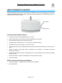
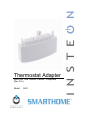
Thermostat Adapter INSTEON® and Totaline/Venstar Compatible (Rev 2.0+) Model : 2441 Thermostat Adapter Owner’s Manual (Rev 2.0+) TABLE OF CONTENTS ABOUT THERMOSTAT ADAPTER ............................................................................................................. 3 Key Thermostat Adapter Features ............................................................................................................ 3 What is Included with Thermostat Adapter ................................................................................................ 3 WHAT IS INSTEON? .................................................................................................................................... 4 INSTALLATION ............................................................................................................................................ 4 Installing Thermostat Adapter.................................................................................................................... 4 Uninstalling Thermostat Adapter ............................................................................................................... 4 CONTROLLING THERMOSTAT ADAPTER FROM AN INSTEON CONTROLER .................................... 5 Linking an INSTEON Controller to Thermostat Adapter ........................................................................... 5 Unlinking Thermostat Adapter from an INSTEON Controller .................................................................... 6 Remotely Controlling your Thermostat ...................................................................................................... 6 CONTROLLING INSTEON RESPONDERS FROM THERMOSTAT ADAPTER ........................................ 7 Linking Thermostat Adapter to an INSTEON Responder ......................................................................... 7 Unlinking an INSTEON Responder from Thermostat Adapter .................................................................. 7 Reporting Changes to Compatible Automation Controller/Software ......................................................... 8 ADVANCED FEATURES ............................................................................................................................. 9 Restoring Power to Thermostat Adapter ................................................................................................... 9 Resetting Thermostat Adapter to its Factory Default Settings .................................................................. 9 ABOUT INSTEON ...................................................................................................................................... 10 Using Dual-Band INSTEON Devices to Upgrade Your Network ............................................................. 10 Important Note about INSTEON Networks; Split Single-Phase vs. 3-Phase Installation........................ 10 Further Enhancing Reliability .................................................................................................................. 10 ADDITIONAL RESOURCES ...................................................................................................................... 10 TROUBLESHOOTING................................................................................................................................ 11 SPECIFICATIONS, CERTIFICATION, AND WARRANTY ........................................................................ 11 Specifications .......................................................................................................................................... 11 Certification .............................................................................................................................................. 11 FCC & Industry Canada Compliance Statement ..................................................................................... 12 Limited Warranty ..................................................................................................................................... 12 Thermostat Adapter Owner’s Manual (Rev 2.0+) ABOUT THERMOSTAT ADAPTER Thermostat Adapter allows you to use the power of INSTEON to control the temperature of your home, from anywhere in the house. Recall stored set points and mode settings from any INSTEON Controller to maintain comfort and save energy. Status LED Set button Key Thermostat Adapter Features • Installs and Links to other INSTEON devices in minutes • Saves energy and money on bills by remotely controlling your thermostat • Communicates wirelessly over radio frequency (RF) • Compatible with Totaline/Venstar T1700, T1800, and T1900 thermostats • Powered through your thermostat – no batteries needed • Automatically controls remote INSTEON devices when the thermostat switches A/C, heat, and fan on or off • Reports changes in thermostat modes, temperature, and humidity to compatible automation controllers or software • Fine-tunes thermostat set points by single degrees from any INSTEON controller with specific Bright and Dim buttons • Stores setup state in memory so settings aren’t lost during power outages • Two-year warranty What is Included with Thermostat Adapter • Thermostat Adapter – INSTEON and Totaline/Venstar Compatible • Quick-Start Guide Page 3 of 13 Thermostat Adapter Owner’s Manual (Rev 2.0+) WHAT IS INSTEON? Since its inception in 2005, INSTEON has become a best-selling home-control networking technology, offering more reliability and flexibility than any other home management system on the market. INSTEON systems are simple, reliable, and affordable. Simple, because each device takes mere minutes to install. Reliable, because every INSTEON device works as a network repeater, ensuring your commands will not be lost. Affordable, because INSTEON can be integrated into any number of devices easily and at a very low cost. An INSTEON home grows in value with each added INSTEON device, making life more convenient, safe, and fun. How Does INSTEON Work? What makes INSTEON the most reliable home automation network is its dual-mesh network. INSTEON devices use both radio frequency (RF) signals and the home’s existing wiring to talk to each other. In an INSTEON network, every INSTEON device also acts as a repeater, receiving and sending every message to all other devices in the network. So by integrating more INSTEON devices you will strengthen the network and ensure no commands will be lost. No central controller or networking setup is required with an INSTEON network. Simply install your devices and then use a series of button presses or taps to Link your devices together. Throughout this Owner’s Manual, you may see the terms “Controller” or “Responder”. These generic INSTEON terms refer to the components of an INSTEON scene, and are used on a scene-by-scene basis. • Controller – sends INSTEON commands to other devices • Responder – reacts to commands sent out by another INSTEON device An INSTEON device may act as a Controller, Responder, or sometimes both. INSTEON networks are also extremely secure. Each INSTEON device is assigned a unique INSTEON ID, so unless neighbors or would-be hackers have access to your particular device’s INSTEON ID, they won’t be able to control your home, even if they are using similar products. INSTALLATION Installing Thermostat Adapter Before installing Thermostat Adapter, be sure that you have properly installed a compatible Totaline/Venstar thermostat. 1) RF-only devices require at least one dual-band INSTEON device, such as an Access Point (#2443), for communication. For the best INSTEON network performance, be sure you have properly installed at least two dual-band devices. 2) Plug Thermostat Adapter into the jack on the bottom of your thermostat The Thermostat Adapter Status LED will turn on solid green Uninstalling Thermostat Adapter 1) Open the front cover of your thermostat by gently pulling the right edge of the cover towards you 2) While pressing firmly on the small round button (located on the bottom center of the thermostat), gently pull down on Thermostat Adapter The Thermostat Adapter Status LED will turn off Page 4 of 13 Thermostat Adapter Owner’s Manual (Rev 2.0+) CONTROLLING THERMOSTAT ADAPTER FROM AN INSTEON CONTROLER Linking an INSTEON Controller to Thermostat Adapter Thermostat Adapter includes a special feature that allows you to Link individual commands to the On and Off buttons on your Controller. For example, you can Link the heat to turn on when you press the On button and Link the fan to turn on when you press the Off button on your Controller. NOTE: Each of the buttons must be Linked separately. If you only Link to the On button, nothing will happen when you press the Off button, unless you specifically program an action to it. The following will work for the most common INSTEON devices: 1) Set the Controller to Linking Mode. (For most Controllers, press & hold an On or Scene button for 10 seconds or the Set button for 3 seconds.) You will have 4 minutes to complete steps 2 and 3 before Linking Mode automatically times out. 2) To Link to an On button: • Set your thermostat to the desired mode (Manual/Program/Auto, Heat/Cool, Temperature, Fan Auto/Fan On) • Tap the Set button on Thermostat Adapter • Press & hold the Set button on Thermostat Adapter for 3 seconds The thermostat display will flash all the LCD characters twice 3) To Link to an Off button: NOTE: Not all INSTEON devices have the ability to be Linked to an Off button (see the device’s Owner’s Manual). • Set your thermostat to the desired mode (Manual/Program/Auto, Heat/Cool, Temperature, Fan Auto/Fan On) • Double-tap the Set button on Thermostat Adapter • Press & hold the Set button on Thermostat Adapter for 3 seconds The thermostat display will flash all the LCD characters twice 4) Test that Linking was successful by changing the mode on your thermostat and tapping the buttons you just Linked to on the Controller NOTE: Different set points can be Linked to different buttons should you need more flexibility. 5) If your Controller is a multi-scene device, you can repeat steps 1 through 4 for as many scenes and set points on your Controller as you wish Page 5 of 13 Thermostat Adapter Owner’s Manual (Rev 2.0+) Unlinking Thermostat Adapter from an INSTEON Controller If you are going to discontinue using Thermostat Adapter, it is very important that you Unlink it from any Linked Controllers. Otherwise, the Controllers will retry any commands repetitively, thus slowing down the system. NOTE: If you Unlink Thermostat Adapter from a single button of an On/Off button pair, any Linked commands for the Controller will be erased, even if the commands were Linked to separate buttons. You will have to re-Link the commands you wish to continue using on your Controller. The following will work for the most common INSTEON devices: 1) Set the Controller to Unlinking Mode. (For most Controllers, press & hold an On or Scene button for 10 seconds twice or the Set button for 3 seconds twice.) You will have 4 minutes to complete the steps 2 and 3 before Unlinking Mode automatically times out. 2) Tap the Set button on Thermostat Adapter 3) Press & hold the Set button on Thermostat Adapter for 3 seconds The thermostat display will flash all the LCD characters twice 4) Confirm that Unlinking was successful by tapping the buttons you just Unlinked from on the Controller 5) If there are any commands you would like to continue using with the Controller, re-Link them with the prior settings. See Linking an INSTEON Controller to Thermostat Adapter. Remotely Controlling your Thermostat Recalling Mode / Set Points Once you have Linked a Controller to Thermostat Adapter, you can recall the mode and set point settings programmed during Linking by tapping the On button on the Controller. Temperature Set Point Adjustments Some devices, such as RemoteLinc (#2440), have specific Dim and Bright buttons which can be used to adjust the current thermostat set point up or down by a single degree. 1) Recall a mode/set point by tapping an On button from a Linked Controller 2) Tap the Bright button to increase or the Dim button to decrease the temperature. Each button tap will adjust the temperature by a single degree. NOTE: While pressing & holding On or Off buttons does dim and brighten other INSTEON devices, Thermostat Adapter will ignore those types of dim/bright commands to prevent “runaway” temperature set points. Page 6 of 13 Thermostat Adapter Owner’s Manual (Rev 2.0+) CONTROLLING INSTEON RESPONDERS FROM THERMOSTAT ADAPTER Linking Thermostat Adapter to an INSTEON Responder Thermostat Adapter can turn INSTEON Responders on and off when the thermostat switches the A/C, heat, and/or fan on and off. This feature is useful for synchronizing your thermostat with other INSTEONcompatible thermostats or equipment, such as booster fans, dampers, etc. • A/C – Turns Responders on when the thermostat turns on the A/C and off when the A/C is turned off • Heat - Turns Responders on when the thermostat turns on the heater and off when the heater is turned of • Fan – Turns Responders on when the fan is turned on manual or via thermostat timer and off when the fan is turned off. NOTE: Although the fan is used during heat and A/C modes, Responders will only turn on and off when the fan is controlled manually, by a Controller, or via thermostat timer. The following will work for the most common INSTEON devices: 1) Set the thermostat to the desired mode (A/C, Heat, FanOn). If you are using the FanOn mode, make sure to also set your thermostat to Off mode. 2) Press & hold the Set button on Thermostat Adapter for 3 seconds The Thermostat Adapter Status LED will begin blinking The thermostat display will flash all the LCD characters once 3) Press & hold the Responder’s Set button for 3 seconds The Thermostat Adapter Status LED will stop blinking The thermostat display will flash all the LCD characters once 4) Confirm that Linking was successfully by manually changing the mode on the thermostat The Responder will respond appropriately Unlinking an INSTEON Responder from Thermostat Adapter If you are no longer going to use an INSTEON Responder that has been Linked to Thermostat Adapter, it is very important that you Unlink it. Otherwise, Thermostat Adapter will retry any commands repetitively, thus slowing down the system. The following will work for the most common INSTEON devices: 1) Press & hold the Set button on Thermostat Adapter for 3 seconds The Thermostat Adapter Status LED will begin blinking The thermostat display will flash all the LCD characters once 2) Press & hold the Set button on Thermostat Adapter for 3 seconds again The Thermostat Adapter Status LED will continue blinking The thermostat display will flash all the LCD characters once 3) Press & hold the Responder’s Set button for 3 seconds The Thermostat Adapter Status LED will stop blinking The thermostat display will flash all the LCD characters once 4) Confirm that Unlinking was successful by manually changing the mode on the thermostat The Responder will no longer respond Page 7 of 13 Thermostat Adapter Owner’s Manual (Rev 2.0+) Reporting Changes to Compatible Automation Controller/Software Thermostat Adapter will report the following changes to an INSTEON-compatible home automation software once a change has been “stabilized” for at least 2 minutes: • Temperature • Humidity • Thermostat mode • Fan mode • Set points NOTE: Thermostat Adapter will only report changes to the last device it was Linked to, using the instructions below. To change the interface to which you’d like the changes to be reported, follow the “Enable” instructions with the new interface as the Responder. While Thermostat Adapter will report to any automation controller or interface you Link to via the following instructions, check the software’s documentation about compatibility with this feature. Enabling Change Reports 1) Set the thermostat to Off mode 2) Press & hold the Set button on Thermostat Adapter for 3 seconds The Thermostat Adapter Status LED will begin blinking The thermostat display will flash all the LCD characters once 3) Press & hold the Responder’s Set button for 3 seconds The Thermostat Adapter Status LED will stop blinking The thermostat display will flash all the LCD characters once Disabling Change Reports 1) Set the thermostat to Off mode 2) Press & hold the Set button Thermostat Adapter for 3 seconds The Thermostat Adapter Status LED will begin blinking The thermostat display will flash all the LCD characters once 3) Press & hold the Set button on Thermostat Adapter for 3 seconds again The Thermostat Adapter Status LED will continue blinking The thermostat display will flash all the LCD characters once 4) Press & hold the Responder’s Set button for 3 seconds The Thermostat Adapter Status LED will stop blinking The thermostat display will flash all the LCD characters once Page 8 of 13 Thermostat Adapter Owner’s Manual (Rev 2.0+) ADVANCED FEATURES Restoring Power to Thermostat Adapter Thermostat Adapter stores all of its settings, such as Links to other INSTEON devices, with non-volatile memory. Because settings are saved in this non-volatile memory, they will not be lost in the event of a power failure. In the event of a power loss Thermostat Adapter will automatically return the load to the state it had before power was interrupted. Resetting Thermostat Adapter to its Factory Default Settings The factory reset procedure can be used to clear the Thermostat Adapter memory of all INSTEON Links, set points, etc. 1) If you are using a Controller to control Thermostat Adapter, be sure to Unlink it from the Controller. See Unlinking Thermostat Adapter from an INSTEON Controller. 2) If you are using Thermostat Adapter to control any Responders, Unlink them from Thermostat Adapter. See Unlinking an INSTEON Responder from Thermostat Adapter. 3) Unplug Thermostat Adapter from your thermostat • Open the cover of the thermostat • While pressing & holding the small round button (located on the bottom center of the thermostat), gently pull down on Thermostat Adapter The Thermostat Adapter Status LED will turn off 4) Wait 10 seconds 5) While pressing & holding the Set button on Thermostat Adapter, plug it back into your thermostat, making sure not to let go of the Set button 6) Continue to hold the Set button for 3 seconds and then release The Thermostat Adapter Status LED will stay off for about 20 seconds and then turn on The thermostat display will flash all the LCD characters three times and then return to normal operation The Thermostat Adapter Status LED will flicker for a few moments and then turn on solid Page 9 of 13 Thermostat Adapter Owner’s Manual (Rev 2.0+) ABOUT INSTEON Using Dual-Band INSTEON Devices to Upgrade Your Network What are phases? The majority of single-family homes in North America have two phases (or “legs”) of 110 Volts coming into their electricity panels. From the panel, they are distributed throughout the home, providing power to outlets and wall switches. These phases come together in some parts of the home to provide 220 Volts of power to large appliances, such as an electric oven or pool pump. Why do I need to bridge these phases? Single-band power line devices send commands via the home’s electricity, but only on a single phase. If the command is intended for a device on the opposite phase, there is a good chance the command will go unnoticed. Installing dual-band INSTEON devices, such as Access Points (#2443), on each phase will allow for devices to communicate between the two phases via RF. Dual-band INSTEON devices embody the full potential of a true INSTEON mesh network. Taking the power line band signal and working in conjunction with the RF band signal, its dual-band function plays out in two ways: • Phase bridger – a receiver of commands, reacting to and translating signals sent from one power phase to the opposite via RF • Signal repeater – a participant in an INSTEON network, repeating commands intended for other devices whether those commands are generated from RF or power line-only devices. To ensure reliability, every INSTEON device confirms that it has received a command. If a Controller does not receive this confirmation, it will automatically retransmit the command up to five times. While using at least one dual-band device is required when using an RF-only device, at least two dual-band devices are recommended in any INSTEON network to ensure reliable communication across two-phase home wiring systems. For larger applications, it is recommended to install at least one dual-band device for every 750 – 1,000 square feet. Search for dual-band INSTEON devices at: www.smarthome.com/dualband Important Note about INSTEON Networks; Split Single-Phase vs. 3-Phase Installation For the best INSTEON network performance, be sure you have properly installed at least two dual-band INSTEON devices. INSTEON has only been officially tested in a split single-phase residential environment but has been known to work in many 3-phase systems, where three dual-band devices are used (one on each phase). However, due to the potential complexity of its troubleshooting, the INSTEON Gold Support Line is unable to support INSTEON in 3-phase environments. Further Enhancing Reliability As signals travel via the power line or RF throughout the home, they naturally become weaker the farther they travel. The best way to overcome weakened signals is to increase the coverage of the mesh network by introducing more INSTEON devices. It is possible that some audio-video devices, computers, power strips, or other electrical equipment may attenuate INSTEON signals on the power line. You can temporarily unplug suspected devices to test whether the INSTEON signal improves. If it does, then you can plug in filters that will permanently fix the problem. ADDITIONAL RESOURCES Find home automation solutions, helpful tips, interactive demos, videos, user forums, and more at the Smarthome Learning Center: www.smarthome.com/learningcenter.html Page 10 of 13 Thermostat Adapter Owner’s Manual (Rev 2.0+) TROUBLESHOOTING Problem The Status LED on Thermostat Adapter is not turning on at all. Thermostat Adapter won’t Link or work with a Controller. Possible Cause Thermostat Adapter may not be getting power. Solution Make sure your thermostat is working properly. Make sure that Thermostat Adapter is properly installed. The Controller might have been reset without Unlinking Thermostat Adapter from it. Re-Link Thermostat Adapter to the Controller. The INSTEON signal may be too weak. Add additional INSTEON devices or move around existing INSTEON devices. All INSTEON devices act as INSTEON network repeaters. Thermostat Adapter may Be sure you have properly installed at least one dualnot be receiving the RF band INSTEON device to ensure communication command. between the units. If you have tried these solutions, reviewed this Owner’s Manual, and still cannot resolve an issue you are having with Thermostat Adapter, please call: INSTEON Gold Support Line 800-762-7845 SPECIFICATIONS, CERTIFICATION, AND WARRANTY Specifications View specifications for Thermostat Adapter at: www.smarthome.com/2441V.html Certification This product has been thoroughly tested by ITS ETL SEMKO, a nationally recognized independent third-party testing laboratory. The North American ETL Listed mark signifies that the device has been tested to and has met the requirements of a widely recognized consensus of U.S. and Canadian device safety standards, that the manufacturing site has been audited, and that the manufacturer has agreed to a program of quarterly factory follow-up inspections to verify continued conformance. Page 11 of 13 Thermostat Adapter Owner’s Manual (Rev 2.0+) FCC & Industry Canada Compliance Statement This device complies with FCC Rules Part 15 and Industry Canada RSS-210 (Rev. 7). Operation is subject to the following two conditions: (1) This device may not cause harmful interference, and (2) This device must accept any interference, including interference that may cause undesired operation of the device. Le present appareil est conforme aux CNR d'Industrie Canada applicables aux appareils radio exempts de licence. L'exploitation est autorise aux deux conditions suivantes: (1) l'appareil ne doit pas produire de brouillage, et (2) l'utilisateur de l'appareil doit accepter tout brouillage radiolectrique subi, mme si le brouillage est susceptible d'en compromettre le fonctionnement. The digital circuitry of this device has been tested and found to comply with the limits for a Class B digital device, pursuant to Part 15 of the FCC Rules. These limits are designed to provide reasonable protection against harmful interference in residential installations. This equipment generates, uses, and can radiate radio frequency energy and, if not installed and used in accordance with the instructions, may cause harmful interference to radio and television reception. However, there is no guarantee that interference will not occur in a particular installation. If this device does cause such interference, which can be verified by turning the device off and on, the user is encouraged to eliminate the interference by one or more of the following measures: • Re-orient or relocate the receiving antenna of the device experiencing the interference • Increase the distance between this device and the receiver • Connect the device to an AC outlet on a circuit different from the one that supplies power to the receiver • Consult the dealer or an experienced radio/TV technician WARNING: Changes or modifications to this device not expressly approved by the party responsible for compliance could void the user’s authority to operate the equipment. Limited Warranty Seller warrants to the original consumer purchaser of this product that, for a period of two years from the date of purchase, this product will be free from defects in material and workmanship and will perform in substantial conformity to the description of the product in this Owner’s Manual. This warranty shall not apply to defects or errors caused by misuse or neglect. If the product is found to be defective in material or workmanship, or if the product does not perform as warranted above during the warranty period, Seller will either repair it, replace it, or refund the purchase price, at its option, upon receipt of the product at the address below, postage prepaid, with proof of the date of purchase and an explanation of the defect or error. The repair, replacement, or refund that is provided for above shall be the full extent of Seller’s liability with respect to this product. For repair or replacement during the warranty period, call the INSTEON Gold Support Line at 800-762-7845 with the Model # and Revision # of the device to receive an RMA# and send the product, along with all other required materials to: Smarthome, Inc. ATTN: Receiving Dept. 16542 Millikan Ave. Irvine, CA 92606-5027 Page 12 of 13 Thermostat Adapter Owner’s Manual (Rev 2.0+) Limitations The above warranty is in lieu of and Seller disclaims all other warranties, whether oral or written, express or implied, including any warranty or merchantability or fitness for a particular purpose. Any implied warranty, including any warranty of merchantability or fitness for a particular purpose, which may not be disclaimed or supplanted as provided above shall be limited to the two-year of the express warranty above. No other representation or claim of any nature by any person shall be binding upon Seller or modify the terms of the above warranty and disclaimer. Home automation devices have the risk of failure to operate, incorrect operation, or electrical or mechanical tampering. For optimal use, manually verify the device state. Any home automation device should be viewed as a convenience, but not as a sole method for controlling your home. In no event shall Seller be liable for special, incidental, consequential, or other damages resulting from possession or use of this device, including without limitation damage to property and, to the extent permitted by law, personal injury, even if Seller knew or should have known of the possibility of such damages. Some states do not allow limitations on how long an implied warranty lasts and/or the exclusion or limitation of damages, in which case the above limitations and/or exclusions may not apply to you. You may also have other legal rights that may vary from state to state. INSTEON Technology Patent U.S Patent No. 7,345,998, International patents pending © Copyright 2011 Smarthome, 16542 Millikan Ave., Irvine, CA 92606, 800-762-7845, www.smarthome.com Rev 04-12-2011 Page 13 of 13