1
SWL-4000AP Series
Access Point User’s Guide
* This User’s Guide can be used on SWL-4000AP and 4000AP(DA).
Notice when you establish
* We recommend you to avoid this places where may be cause of performance decline or trouble.
1.
2.
3.
4.
5.
Places with high humidity or wet condition
Places with extreme temperature(too hot or too cold)
Places where change of temperature is extreme
Places with a lot of dusts
Places sealed with thick walls or still structure
Notice when you use
1. Do not disassembly on your own.
2. Do not drop the product or give excessive impact.
3. Do not twist or lengthen the power cord.
4. Do not place any object on the product.
5. Do not use any parts or components, which are not provided.
6. Use only the power adapter provided.
This Guide is a copyright of :
Samsung Electro-Mechanics Co., Ltd.
314 Maetan-3 Dong, Paldal-Gu
Suwon, Kyunggi-Do, 442-743
Korea.
SWL-4000AP Series Access Point User’s Guide
First Edition (November 2001)
Models subjected to this User’s Guide :
SWL-4000AP, 4000AP(DA)
* DA : Dipole Antenna Type
Table of Contents
1.
Introduction⋅⋅⋅⋅⋅⋅⋅⋅⋅⋅⋅⋅⋅⋅⋅⋅⋅⋅⋅⋅⋅⋅⋅⋅⋅⋅⋅⋅⋅⋅⋅⋅⋅⋅⋅⋅⋅⋅⋅⋅⋅⋅⋅⋅⋅⋅⋅⋅⋅⋅⋅⋅⋅⋅⋅⋅⋅⋅⋅⋅⋅⋅⋅⋅⋅⋅ 1
2.
Installation⋅⋅⋅⋅⋅⋅⋅⋅⋅⋅⋅⋅⋅⋅⋅⋅⋅⋅⋅⋅⋅⋅⋅⋅⋅⋅⋅⋅⋅⋅⋅⋅⋅⋅⋅⋅⋅⋅⋅⋅⋅⋅⋅⋅⋅⋅⋅⋅⋅⋅⋅⋅⋅⋅⋅⋅⋅⋅⋅⋅⋅⋅⋅⋅⋅⋅⋅⋅ 3
3.
AP Basic Setting Using AP Manager⋅⋅⋅⋅⋅⋅⋅⋅⋅⋅⋅⋅⋅⋅⋅⋅⋅⋅⋅⋅⋅⋅⋅⋅⋅⋅⋅
4.
PTP Setting Using AP Manager⋅⋅⋅⋅⋅⋅⋅⋅⋅⋅⋅⋅⋅⋅⋅⋅⋅⋅⋅⋅⋅⋅⋅⋅⋅⋅⋅⋅⋅⋅⋅⋅⋅⋅⋅ 10
5.
AML Setting Using AP Manager⋅⋅⋅⋅⋅⋅⋅⋅⋅⋅⋅⋅⋅⋅⋅⋅⋅⋅⋅⋅⋅⋅⋅⋅⋅⋅⋅⋅⋅⋅⋅⋅⋅ 14
6.
Bridge Table and Protocol Management Using
APManager⋅⋅⋅⋅⋅⋅⋅⋅⋅⋅⋅⋅⋅⋅⋅⋅⋅⋅⋅⋅⋅⋅⋅⋅⋅⋅⋅⋅⋅⋅⋅⋅⋅⋅⋅⋅⋅⋅⋅⋅⋅⋅⋅⋅⋅⋅⋅⋅⋅⋅⋅⋅⋅⋅⋅⋅⋅⋅⋅⋅⋅⋅⋅⋅
5
19
7.
NAT Setting Using AP Manager⋅⋅⋅⋅⋅⋅⋅⋅⋅⋅⋅⋅⋅⋅⋅⋅⋅⋅⋅⋅⋅⋅⋅⋅⋅⋅⋅⋅⋅⋅⋅⋅⋅⋅ 22
8.
DHCP Server Setting Using AP Manager⋅⋅⋅⋅⋅⋅⋅⋅⋅⋅⋅⋅⋅⋅⋅⋅⋅⋅⋅⋅ 27
9.
NAT and DHCP Server Simultaneous Setting Using
AP Manager ⋅⋅⋅⋅⋅⋅⋅⋅⋅⋅⋅⋅⋅⋅⋅⋅⋅⋅⋅⋅⋅⋅⋅⋅⋅⋅⋅⋅⋅⋅⋅⋅⋅⋅⋅⋅⋅⋅⋅⋅⋅⋅⋅⋅⋅⋅⋅⋅⋅⋅⋅⋅⋅⋅⋅⋅⋅⋅⋅⋅⋅⋅⋅⋅⋅ 32
10. ADSL and Cable Modem Connection Setting Using
AP Manager ⋅⋅⋅⋅⋅⋅⋅⋅⋅⋅⋅⋅⋅⋅⋅⋅⋅⋅⋅⋅⋅⋅⋅⋅⋅⋅⋅⋅⋅⋅⋅⋅⋅⋅⋅⋅⋅⋅⋅⋅⋅⋅⋅⋅⋅⋅⋅⋅⋅⋅⋅⋅⋅⋅⋅⋅⋅⋅⋅⋅⋅⋅⋅⋅ 35
11. Encryption Setting Using AP Manager⋅⋅⋅⋅⋅⋅⋅⋅⋅⋅⋅⋅⋅⋅⋅⋅⋅⋅⋅⋅⋅⋅⋅⋅ 44
12. User Access Control Setting Using AP Manager⋅⋅⋅⋅⋅⋅⋅⋅⋅ 48
13. Firmware Upgrade Using AP Manager ⋅⋅⋅⋅⋅⋅⋅⋅⋅⋅⋅⋅⋅⋅⋅⋅⋅⋅⋅⋅⋅⋅⋅ 53
14. Data Transmission Status Check Using AP Manager⋅
56
15. AP Setting Using Web Browser⋅⋅⋅⋅⋅⋅⋅⋅⋅⋅⋅⋅⋅⋅⋅⋅⋅⋅⋅⋅⋅⋅⋅⋅⋅⋅⋅⋅⋅⋅⋅⋅⋅
59
16. AP Setting Using TELNET⋅⋅⋅⋅⋅⋅⋅⋅⋅⋅⋅⋅⋅⋅⋅⋅⋅⋅⋅⋅⋅⋅⋅⋅⋅⋅⋅⋅⋅⋅⋅⋅⋅⋅⋅⋅⋅⋅⋅⋅
61
17. HyperTerminal Setting for RS-232C(COM Port)
Communication⋅⋅⋅⋅⋅⋅⋅⋅⋅⋅⋅⋅⋅⋅⋅⋅⋅⋅⋅⋅⋅⋅⋅⋅⋅⋅⋅⋅⋅⋅⋅⋅⋅⋅⋅⋅⋅⋅⋅⋅⋅⋅⋅⋅⋅⋅⋅⋅⋅⋅⋅⋅⋅⋅⋅⋅⋅⋅⋅ 62
18. AP Basic Setting Using RS-232C(COM Port)⋅⋅⋅⋅⋅⋅⋅⋅⋅⋅⋅⋅⋅ 65
19. Load Default Values Using RS-232C(COM Port)⋅⋅⋅⋅⋅⋅⋅⋅ 72
20. Firmware Upgrade Using RS-232C(COM Port)⋅⋅⋅⋅⋅⋅⋅⋅⋅
73
APPENDIX Ⅰ.
Explanation of Basic Configuration to use AP Manager
77
APPENDIX Ⅱ.
Specification⋅⋅⋅⋅⋅⋅⋅⋅⋅⋅⋅⋅⋅⋅⋅⋅⋅⋅⋅⋅⋅⋅⋅⋅⋅⋅⋅⋅⋅⋅⋅⋅⋅⋅⋅⋅⋅⋅⋅⋅⋅⋅⋅⋅⋅⋅⋅⋅⋅⋅⋅⋅⋅⋅⋅⋅⋅⋅⋅⋅⋅⋅⋅⋅⋅⋅⋅⋅⋅ 82
Also, this equipment is available for home use.
This device complies with part 15 of the FCC Rules.
Operation is subject to the following two conditions:
(1) This device may not cause harmful interference, and
(2) this device must accept any interference received,
including interference that may cause undesired operation.
1. Introduction
Thank you for purchasing SAMSUNG SWL-4000AP Series Access Point (AP).
This guide describes the installation and basic configuration of the Access Point.
Standard Model is SWL-4000AP for example.
AP Components
!
!
!
!
!
!
SWL-4000AP Series Access Point
Wireless LAN Card
RS-232C Serial Cable
Power Adaptor
Specific power cord for each country
CD (AP Manager , User’s Guide)
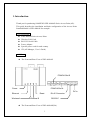
AP View
! The Front and Rear View of SWL-4000AP
PCMCIA Slot B
PCMCIA Slot A
Power
DC in
Ethernet
Wireless A
Reset
Wireless B
RJ-45 Connector
RS-232C
! The Front and Rear View of SWL-4000AP(DA)
1
2
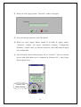
2. Installation
① Choose the place with the consideration of power outlet and network
connection (RJ-45 Cable connection) to install the Access Point.
② Plug in the power cord to the power outlet and the power adapter.
Plug in the DC output to “DC in”. Make sure that the “Power” LED is on. If the
“Power” LED is not on, please check the connections of the power cord.
Notice : Use the supplied power adapter(DC 5V, 2A) only to prevent the
permanent failure of AP.
③ Confirm that “Wireless” LED of AP blinks.
If not, confirm that Wireless LAN Card of AP is properly mounted in case for
4000AP and 4000AP(DA). The card should be inserted or extracted when the
power is off, and we are not responsible for any product failure due to
disassembly by users.
Notice : Use the supplied Wireless LAN card(3.3V) only to prevent the
permanent failure of AP.
④ Attach UTP Ethernet cable to the RJ-45 Connector.
Make it sure that the “Ethernet” LED is on. If the “Ethernet” LED is on, you
can use the existing network with the Access Point; otherwise check the UTP
cable connections.
⑤ Attach RS-232C serial cable to the Access Point and the PC.
The parameters of Access Point can be configured through the connection of
RS-232C serial cable to the PC(Refer to Chapter 17).
⑥ When AP Manager is used, you may skip the step ⑤.
⑦ Change settings of AP according to user’ s selection referring User’ s Guide.
3
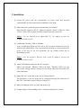
⑧ Insert Wireless LAN Card into your PC.
Wireless LAN Cards are available both for desktop and notebook PCs. PCI
Wireless LAN Card is used for the desktop PC where as the PCMCIA Wireless
LAN Card is for the notebook PC only. For more information about PCI and
PCMCIA Wireless LAN Cards, please visit http://www.magiclan.com.
⑨ Enter the same ESSID that you have set for the Access Point, using the
Wireless LAN Card utility running on your PC.
⑩ Through AP, which is installed and set by the method above, you can
communicate between server and PC with installed Wireless LAN Card.
Ethernet, ADSL,
and Cable Modem
SWL-4000AP
[Models subjected to this User’ s Guide]
SWL-4000AP(DA)
4
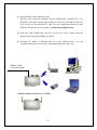
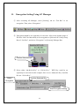
3. AP Basic Setting Using AP Manager
① Execute AP Manager(SWL-3000AP Series, 4000AP Series Management
Utility) under MS-Windows 95/98/Me/2000/NT/XP operating system.
② After choosing AP, which will be used by users, on “List Box” of AP Manager
using mouse, select [Basic] tab for any changes on setting.
③ AP information of the selected AP will appear on [Selected AP’s Info] Group
Box. You may refer to APPENDIX Ⅰ for detailed explanation.
5
④ TCP/IP address environment is set on [Basic] Dialogue Box.
♦ Specify an IP address
After consulting with your system administrator, you enter IP Address,
Subnet Mask and Gateway Address.
♦ Obtain an IP address automatically
This setting is possible when AP is used for DHCP Client.
⑤ Set ESSID and Channel number. Description is a parameter not related with
any operation, and it is used only to record description or stored location of AP.
We recommend you use different ESSID and Channel for each slots
♦ Set ESSID for AP use.
ESSID (Max. 32 Characters) must consist of alphabetic and numeric
characters excluding blank and special characters(Capital•Small letter
distinction).
6
♦ Set Channel for AP use.
Channel index should be between 1 and 14(differs from country to country).
Notice : If you are operating two or more Access Points in the adjoining
cells, keep the appropriate channel distance to avoid the interference. We
recommend you to keep the distance of at least 4 channels in the adjoining
cells.
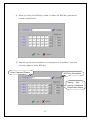
⑥ Select “Change Password” on [File] menu if you want to change the password.
⑦ After entering Current Password, New Password and Retype Password, click
[OK] button.
Please keep this password at a safe place or keep it where it may not get lost.
7
⑧ When you click [Confirm & Apply] button to apply new configuration,
“Configuration Summary” window, which shows new configuration, will
appear.
Confirm New
Configuration
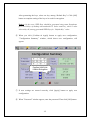
⑨ If new settings are entered correctly, click [Apply] button to apply new
configuration.
⑩ When you click [Apply] button, “Password” window will appear. The default
password is “public”, and user can change password later.
8
⑪ After you enter the password, click [OK] button.
⑫ If you want to set default values, click [Load Default values] button. Then, AP
Configuration will return to default setting.
Resetting to
Default Values
9
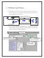
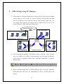
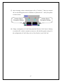
4. PTP Setting Using AP Manager
① PTP stands for Point to Point, and it is used to connect two divided networks
into one using one slot of AP as Wireless Bridge. In this case, the other slot is
used for capabilities of Access Point.
(Hub)
Internet Network
< Point to Point Area>
< AP Slot Area>
< AP Slot Area>
② After executing AP Manager, select [Radio] tab on “Tab Bar”. Select slot to set
PTP on “List Box” using mouse(by click the shape of Wireless LAN Card), and
confirm setting status on [Radio] Dialogue Box.
Confirm Slot
Confirm AP Operation Mode
MAC ID of Wireless LAN
Card on Selected Slot
“Default Values”
Recommended
10
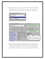
③ When Operation Mode of AP is selected for “Point-to-Point” on [Radio]
Dialogue Box, [Remote ID (PTP)] Box will appear to enter MAC ID of
Wireless LAN Card on other AP, which will be connected by using PTP mode.
Setting MAC ID of other
Wireless LAN Card to be
Connected Using PTP Mode
④ When [Edit] button on [Remote ID (PTP)] Box is selected, [MAC ID] Box,
which is to enter(for entering) MAC ID of Wireless LAN Card of other AP to
be connected, will appear. After entering MAC ID, click [OK] button to
complete setting. MAC ID setting can be confirmed on [Remote ID (PTP)] Box.
11
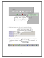
Confirm MAC ID Setting of
other Wireless LAN Card to be
connected using PTP Mode
⑤ ESSID and Channel of two APs must be identical in PTP mode
Enter the Same ESSID and
Channel of two APs in PTP Mode
⑥ When you click [Confirm & Apply] button to apply new configuration,
PTP new configuration, will
“Configuration Summary” window,Confirm
which shows
Mode Setting
appear.
12
Confirm Common
ESSID and
Channel for AML
Mode Setting
Confirm AML
Mode Setting
⑦ If new settings are entered correctly, click [Apply] button to apply new
configuration.
⑧ When you click [Apply] button, “Password” window will appear.
⑨ After you enter the password, click [OK] button.
⑩ When you click [Apply] button instead of [Confirm & Apply] button,
“Password” window will appear immediately skipping “Configuration
Summary” window. After you enter the password, click [OK] button to apply
new configuration.
13
⑪ After rebooting, choose selected proper AP on “List Box”. Then, the selected
slot set with PTP Mode can be confirmed on [Selected AP’s Info] Group Box
as shown below.
Confirm PTP
Mode Setting
14
5. AML Setting Using AP Manager
① AML stands for Automatic Multi-link. Using one slot of AP as Wireless Bridge
and the other as Access Point, it is used to connect several divided networks
into one. It connects several [Slave]s with one main [Master]. In this case, you
can consist Wire Network by connect Hub to Ethernet Port of AP or can
connect Ethernet, ADSL and Cable Modem to it.
Internet Network
<AP Slot Area>
(Hub)
<Wire Network using Hub>
[Master]
[Slave]
<AP Slot Area>
[Slave]
<AML Slot Area>
<AP Slot Area>
② After executing AP Manager, click [Radio] tab on “Tab Bar”. After selecting
slot to set AML on “List Box” using mouse(by click the shape of Wireless
LAN Card), set Operation Mode with “Automatic Multi-link” on [Radio]
Dialogue Box.
③ When “Automatic Multi-link” on [Radio] Dialogue Box is selected, [Automatic
Multi-link] Box, which sets AP status(Master or Slave) in AML mode, will
appear.
15
④ Select either “Master” or “Slave” for [Control Mode] on [Automatic Multi-link]
Box. Basically, AML Mode consists of two or more APs, and set one for
“Master” and the rest for “Slave”s.
Confirm Slot
Confirm AP Operation
Mode Setting
Setting AML Control Mode
Default Value for “Monitor
Interval” Recommended
Confirm AML Control Mode Setting
16
⑤ All of ESSID and Channel of AP set in AML mode must be identical.
Enter the Same ESSID and
Channel of all APs in AML Mode
⑥ When you click [Confirm & Apply] button to apply new configuration,
“Configuration Summary” window, which shows new configuration, will
appear.
Confirm Common
ESSID and
Channel for AML
Mode Setting
Confirm AML
Mode Setting
⑦ If new settings are entered correctly, click [Apply] button to apply new
configuration.
17
⑧ When you click [Apply] button, “Password” window will appear.
⑨ After you enter the password, click [OK] button.
⑩ When you click [Apply] button instead of [Confirm & Apply] button,
“Password” window will appear immediately skipping “Configuration
Summary” window. After you enter the password, click [OK] button to apply
new configuration.
⑪ After rebooting, choose selected proper AP on “List Box”. Then, the selected
slot set with AML Mode can be confirmed on [Selected AP’s Info] Group
Box as shown below.
Confirm AML
Mode Setting
18
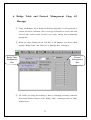
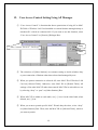
6. Bridge Table and Protocol Management Using AP
Manager
① Using AP Manager, list of Wired and Wireless Station(PC or AP) connected to
current AP can be confirmed. Also, it sets type of Protocol to receive and send
selected data, which satisfy Protocol user wants, among data transmitting
through AP.
② When you select [Bridge] tab on “Tab Bar” of AP Manager, two boxes, which
manage “Bridge Table” and “Protocol” on Dialogue Box, will appear.
Bridge Table
Management
Box
Protocol
Management
Box
③ AP enables receiving and sending of data by managing currently connected
Wired and Wireless Stations with “Bridge Table” consisting values of MAC
Address form.
19
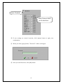
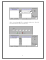
④ [Age Time] on [Bridge Table] Management Box shows cycle of AP refreshing
“Bridge Table”. The use of Default Values is recommended.
⑤ After selecting Station Type you want with Radio button to refresh Stations
connected to current AP, click [Refresh Bridge Table] button to confirm.
Confirm Refresh
Bridge Table
Number
of
Stations
Radio Button
for Selecting
Station Type
MAC Address Information
of Connected Stations
⑥ [Bridge Table] Management Box enables confirmation of Wired and Wireless
Stations connected with current AP only.
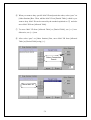
⑦ You can block Protocol you do not want using [Protocol] Management Box.
When Protocol use is limited, some specific applications may not operate.
Therefore, before setting, consult your system administrator. “Disabled” of
Default Value is recommended.
⑧ Selecting “Disabled” checkbox on [Protocol] Management Box leads to
“Enabled”. Then, whole [Protocol] Management Box is activated to enable
selecting.
⑨ If you select any Protocol what you do not want among Protocols shown on
[Protocol] Management Box, a phrase of “Pass” changes to “Drop”.
20
Select “Enabled”
Select Protocol Which
You Do Not Want
⑩ If new settings are entered correctly, click [Apply] button to apply new
configuration.
⑪ When you click [Apply] button, “Password” window will appear.
⑫ After you enter Password, click [OK] button.
21
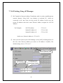
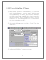
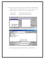
7. NAT Setting Using AP Manager
① NAT stands for Network Address Translation, and it is used to establish private
network domain. Using NAT, any desktop or notebook PC, which are
connected to AP, may freely use any private IP Address. In this case, the
private IP Address must have same Network Address assigned for NAT IP
Address.
For Example)
NAT IP Address
:
172.16.0.1
Station IP Address #1
:
172.16.0.100
Station IP Address #2
:
172.16.0.150
In this case, Network Address is 172.16.0.X.
② After you select [Server] tab of AP Manager, select [NAT] on Dialogue Box. In
this case, enter Gateway Address you select on “IP Address” of [NAT]. The
default setting value is “172.16.0.1”.
Select [Server] Tab
NAT Setting
IP Address and
Subnet Mask Setting
22
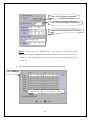
③ When you click [Confirm & Apply] button to apply new configuration,
“Configuration Summary” window, which shows new configuration, will
appear.
Confirm NAT
Setting
④ If new settings are entered correctly, click [Apply] button to apply new
configuration.
⑤ When you click [Apply] button, “Password” window will appear.
⑥ After you enter the password, click [OK] button.
23
⑦ When you click [Apply] button instead of [Confirm & Apply] button,
“Password” window will appear immediately skipping “Configuration
Summary” window. After you enter the password, click [OK] button to apply
new configuration.
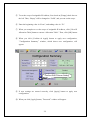
⑧ After rebooting, choose selected proper AP on “List Box”. Then, the selected
AP set with NAT can be confirmed on [Selected AP’s Info] Group Box as
shown below.
Confirm NAT Setting
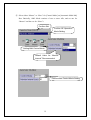
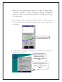
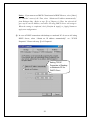
⑨ Configuration of Desktop or notebook PC to connect with AP under MSWindows is shown below.
Right-click [Network
Neighborhood] Icon
from Desktop to Show
menu.
Select “Properties” on
[Network Neighborhood]
Menu.
24
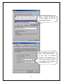
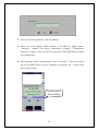
Select “TCP/IP” [Properties]
of LAN Adapter to use on
[Configuration] Menu.
Set “IP Address” and “Subnet
Mask” on [IP Address] Menu.
In this case, IP Address
entered on “IP Address” must
have same Network Address
of IP Address of AP assigned
for NAT.(Refer step ①.)
25
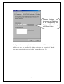
Gateway Address must
have same as “IP Address”
of AP assigned by NAT
Setting on “New Gateway”
of [Gateway] Menu.
Configuration has been completed for desktop or notebook PC to connect with
AP. In this case, the specified IP Address of desktop or notebook PC should
have same network address as set by NAT setting.(Refer step ①.)
26
8. DHCP Server Setting Using AP Manager
① DHCP stands for Dynamic Host Configuration Protocol, it is protocol that
enables Network administrator to manage and assign IP Address in system
centrally. DHCP manages and assigns IP Address for network administrator,
and it enables computer to get assigned IP Address when it is connected to
other place in the network. However, any changes of IP Address of Web server
and FTP server may cause confusion. Therefore, fixed IP Address should be
used, and we recommend not to use DHCP.
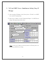
② After executing AP Manager, select [Server] tab on “Tab Bar”. Then, select
“DHCP Server”.
Select Server
Select DHCP Server
③ Configuration of “DHCP Server” is shown on the next page.
27
Scope of IP Address Assignable
Lease Time for Assigned IP Address
Assessed Information with IP Address
Notice : When you select DHCP Server, the values on the window show
information assigned to DHCP Client with IP Address. In most cases, values of
“Gateway” and “Submask” are same as those of Gateway and Submask of
current AP.
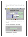
④ Click [Edit IP Scope] button, and the window below will appear.
Select [Empty]
Delete Current IP Allocation Table
28
⑤ To set the scope of assignable IP Address, first check on [Empty] check box on
the left. Then, “Empty” will be changed to “Valid”, and you can set the scope.
⑥ Enter the beginning value in “From”, and ending value in “To”.
⑦ When you complete to set the scope of assignable IP Address, click [Clear IP
Allocation Table] button to current “Allocation Table”. Then, click [OK] button.
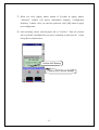
⑧ When you click [Confirm & Apply] button to apply new configuration,
“Configuration Summary” window, which shows new configuration, will
appear.
Confirm DHCP Server Setting
⑨ If new settings are entered correctly, click [Apply] button to apply new
configuration.
⑩ When you click [Apply] button, “Password” window will appear.
29
⑪ After you enter the password, click [OK] button.
⑫ When you click [Apply] button instead of [Confirm & Apply] button,
“Password” window will appear immediately skipping “Configuration
Summary” window. After you enter the password, click [OK] button to apply
new configuration.
⑬ After rebooting, choose selected proper AP on “List Box”. Then, the selected
AP set with DHCP Server can be confirmed on [Selected AP’s Info] Group
Box as shown below.
Confirm DHCP
Server Setting
30
Notice : If you want to set DHCP Client instead of DHCP Server, select [Basic]
on “Tab Bar” menu of AP. Then, select “Obtain an IP address automatically”
from Dialogue Box. (Refer to step ④ of Chapter 6.) Then, the selected AP
gives up its own IP Address, and other AP using DHCP Server will assign it.
When the setting is completed, click [Confirm & Apply] or [Apply] button to
apply new configuration.
⑭ In case of DHCP connection with desktop or notebook PC of user to AP using
DHCP Server, select “Obtain an IP address automatically” on “TCP/IP
Properties”. Please refer step ⑨ of Chapter10.
Setting TCP/IP
Properties of Desktop
or Notebook PC for
DHCP Client
31
9.
NAT and DHCP Server Simultaneous Setting Using AP
Manager
① After executing AP Manager, select [Server] tab on “Tab Bar” to set DHCP
Server and NAT simultaneously.
② Please refer to Chapter 10 for NAT Setting and Chapter 11 for DHCP Server
Setting. This chapter shows default values.
Server Setting
DHCP Server Setting
Refer to Notice
NAT Setting
Notice : In this case, IP Address as Gateway format in NAT Setting must be set
for Gateway of DHCP Server Setting.
32
③ When you click [Confirm & Apply] button to apply new configuration,
“Configuration Summary” window, which shows new configuration, will
appear.
Confirm NAT and
DHCP Setting
④ If new settings are entered correctly, click [Apply] button to apply new
configuration.
⑤ When you click [Apply] button, “Password” window will appear.
⑥ After you enter the password, click [OK] button.
33
⑦ When you click [Apply] button instead of [Confirm & Apply] button,
“Password” window will appear immediately skipping “Configuration
Summary” window. After you enter the password, click [OK] button to apply
new configuration.
⑧ After rebooting, choose selected proper AP on “List Box”. Then, the selected
AP set with NAT and DHCP Server can be confirmed on [Selected AP’s Info]
Group Box as shown below.
Confirm NAT Setting
Confirm DHCP Server Setting
34
10.
ADSL and Cable Modem Connection Setting Using AP
Manager
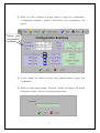
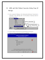
① After executing AP Manager, click [Advanced] and [Internet Connection] on
“Menu Bar” in the following order. Or click [Internet Connection] button on
[Basic] Dialogue Box.
Select on “Menu Bar”
Select on “Dialogue Box”
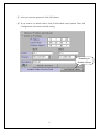
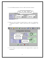
② Then the Internet Connection Setup page(default page) will appear.
Select your Internet connection service type and click
35
Notice:
ADSL can generally be divided into two service types supporting
PPPoE or PPTP, but PPPoE is more common. If you don’t know your ADSL
service type, please check the Website or contact your ISP to find out service
type you are using.
③ Go to 10.1 for PPPoE, 10.2 for PPTP, and 10.3 for Cable Modem
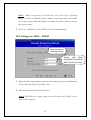
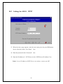
10.1 Settings for ADSL – PPPoE
Auto-connect on
Booting Setting
Setting
with
Basic
Information Provided by
ADSL Service Provider
① When the above page appears, enter the user name given by your ISP(Internet
Service Provider) in the “User Name” box.
② Enter the password in the “Password” box.
Notice: If PPPoE service name setting is not selected for Auto, PPPoE service
name will be required
36
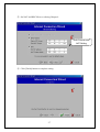
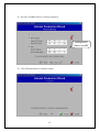
③ Set NAT and DHCP Server referring Chapter 9.
DHCP Server and
NAT Setting
④ Click [Finish] button to complete setting.
37
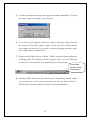
⑤ A window will appear and ask you to apply new settings immediately. If you do
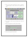
not want to apply new settings, select [No(N)].
⑥ If you click [Yes(Y)] button, “Password” window will appear. After you enter
the password, click [OK] button to apply. In case you select [No(N)] button,
new settings will be saved. If you want to continue applying procedure again,
click [Apply] button on “Button Bar”.
⑦ When you click [Basic] tab on “Tab Bar,” ADSL Connection Status will appear
in Dialogue Box. The connection status will show “N/A” for Access Point and
“Connected”, “Disconnected” and “Negotiating” for ADSL Setting.
Connected
Disconnected
Negotiating
⑧ Clicking [ADSL State(Connected, Disconnected, Negotiating)] button enables
you to disconnect. On the other hand, when you click the button while it is
disconnected, you can re-connect according to selected information.
38
10.2 Settings for ADSL – PPTP
① When the above page appears, enter the user name given by your ISP(Internet
Service Provider) in the “User Name” box.
② Enter the password in the “Password” box.
③ Enter the IP Address of PPTP Server in the “PPTP Server IP Address” box
Notice: In case IP Address of PPTP Server are unknow, contact your ISP.
39
④ Set NAT and DHCP Server referring Chapter 9.
Setting DHCP
Server and NAT
⑤ Click [Finish] button to complete setting.
40
⑥ A window will appear and ask you to apply new settings immediately. If you do
not want to apply new settings, select [No(N)].
⑦ If you click [Yes(Y)] button, “Password” window will appear. After you enter
the password, click [OK] button to apply. In case you select [No(N)] button,
new settings will be saved. If you want to continue applying procedure again,
click [Apply] button on “Button Bar”.
⑧ When you click [Basic] tab on “Tab Bar,” ADSL Connection Status will appear
in Dialogue Box. The connection status will show “N/A” for Access Point and
“Connected”, “Disconnected” and “Negotiating” for ADSL Setting.
Connected
Disconnected
Negotiating
⑨ Clicking [ADSL State(Connected, Disconnected, Negotiating)] button enables
you to disconnect. On the other hand, when you click the button while it is
disconnected, you can re-connect according to selected information.
41
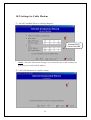
10.3 Settings for Cable Modem
① Set NAT and DHCP Server referring Chapter 9.
Setting DHCP
Server and NAT
Notice : Personal Information Setting is not needed because Cable modems are
generally given with fixed IP Address.
② Click [Finish] button to complete setting.
42
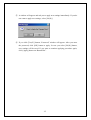
③ A window will appear and ask you to apply new settings immediately. If you do
not want to apply new settings, select [No(N)].
④ If you click [Yes(Y)] button, “Password” window will appear. After you enter
the password, click [OK] button to apply. In case you select [No(N)] button,
new settings will be saved. If you want to continue applying procedure again,
click [Apply] button on “Button Bar”.
43
11. Encryption Setting Using AP Manager
① After executing AP Manager, select [Security] tab on “Tab Bar” to set
encryption. Then, select “Encryption”.
② Encryption should be set separately for each slot. After select slot(the shape of
Wireless LAN Card described) to set encryption on [Selected AP’s Info] Group
Box of “List Box”, and select “Encryption” on [Security] Dialogue Box.
Confirm Selected Slot
③ Select either “64(40)-bit Key” or “128-bit Key.”
WEP Key could be set
separately for each slot. In this example, Slot A is set “64(40)-bit Key” and Slot
B is set “128-bit Key”.
Select
Encryption
Confirm Selected Slot
Start Encryption Setting
44
④ When you select [Set WEP Key] button, a window for WEP Key generation is
created as shown below.
⑤ Enter the agreed password phrase to set encryption in “Passphrase,” and click
[Generate] button to create WEP Key.
Enter Password Phrase
WEP Key Generation
Setting “Key 1”
among Generated
Default Key Values
45
After generating the keys, select one key among “Default Key”s. Click [OK]
button to complete setting of the key to be used for encryption.
Notice : In this case, WEP Keys should be generated using same Passphrase
for Card Utility of desktop and notebook PC. Select same key, which is also
selected by AP, among generated WEP Keys for “Default Key” value.
⑥ When you click [Confirm & Apply] button to apply new configuration,
“Configuration Summary” window, which shows new configuration, will
appear.
Confirm 64(40)-bit
/128-bit Encryption
⑦ If new settings are entered correctly, click [Apply] button to apply new
configuration.
⑧ When “Password” window appear, enter the password. Then click [OK] button.
46
⑨ After rebooting, choose selected proper AP on “List Box”. Then, the selected
AP set with Encryption can be confirmed on [Selected AP’s Info] Group Box
as shown below.
Confirm Slot A
Encryption Setting
Confirm Slot A
Encryption Setting
⑩ Change configuration of Card Utility(installed Wireless LAN Card) of desktop
or notebook PC, which is wanted to connect to AP with Encryption setting. For
the configuration of Card Utility, refer to User Guide of your LAN Card
47
12. User Access Control Setting Using AP Manager
① “User Access Control” is function that shows permission of using AP to MAC
ID Table of Wireless LAN Card installed on certain Stations among desktop or
notebook PC, which are connected AP. If you want to use this function, select
“User Access Control” on [Security] Dialogue Box.
Deny
“User Access Control” Setting
Pass
② The selections of [Other Stations] are common setting to decide whether deny
or pass connection of Stations other than selected and managed by user.
③ When you permit connection to selected AP, enter MAC ID of Wireless LAN
Card on [Allowed Table]. Otherwise, enter MAC ID on [Denied Table]. All
settings of the other MAC ID other than entered MAC IDs in each table are set
by selecting “deny” or “pass” on [Other Stations] Box.
④ When MAC ID is added on each table, use [+] icon. On the other hand, when
deleted, use [-] icon.
⑤ When you want to permit specific MAC ID and deny the other, select “deny”
on [Other Stations] Box. Then, enter the MAC ID on [Allowed Table], which is
you want to permit.
48
Select Connection Deny
Click [+] icon, and enter MAC ID as shown on the window below. Then, click
[OK] button to add MAC ID on [Allowed Table].
49
⑥ When you want to deny specific MAC ID and permit the other, select “pass” on
[Other Stations] Box. Then, add the MAC ID on [Denied Table], which is you
want to deny. MAC ID can be entered by the method explained on ⑤ and also
move MAC ID from [Allowed Table].
⑦ To move MAC ID from [Allowed Table] to [Denied Table], use [>>] icon.
Otherwise, use [<<] icon.
⑧ After select “pass” on [Other Stations] Box, move MAC ID from [Allowed
Table] to [Denied Table] using [>>].
Select Connection
Permit
Move MAC ID
50
⑨ If you want to export and save MAC IDs registered either on [Allowed Table]
or [Denied Table], click [Export] button. Then, it will be saved where user
wants as “granted.lst” or “denied.lst”. You can rename the file name.
# granted.lst
-> MAC ID List on [Allowed Table]
# denied.lst
-> MAC ID List on [Denied Table]
Save MAC ID
File name.lst
On the other hand, click [Import] button to import saved MAC ID Lists.
51
⑩ You can combine and use various settings as you wish.
⑪ If new settings are entered correctly, click [Apply] button to apply new
configuration.
⑫ When “Password” window appear, enter the password. Then, click [OK] button.
52
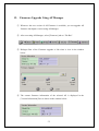
13. Firmware Upgrade Using AP Manager
① Whenever the new version of AP Firmware is available, you can upgrade AP
firmware into higher version using AP Manager.
② After executing AP Manager, select [Firmware] tab on “Tab Bar”.
③ Dialogue Box of the Firmware upgrade is like what is view in the window
below.
④ The current firmware information of the selected AP is displayed in the
[Version Information] Box as shown in the window below.
53
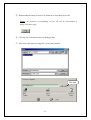
⑤ Downloaded the latest version of AP firmware in local disk of your PC
Notice: AP firmware corresponding to your AP can be downloaded in
MagicLAN home page.
⑥ Click the file icon shown below on Dialogue Box.
⑦ After select the firmware image file, click [Open] button.
File Icon
54
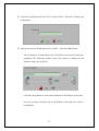
⑧ Click the [Load] button after the file is selected. Then, “Password” window will
be displayed.
⑨ Enter the password, default password is “public”, and click [OK] button.
The AP firmware is loaded from your Local Disk to the Access Point and is
upgraded. The following window shows the status of loading the AP
firmware image file to the AP.
Click the [Stop] button to cancel the download of AP firmware at any time.
An error message will show up if AP firmware other than you select is
downloaded.
55
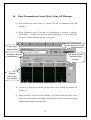
14. Data Transmission Status Check Using AP Manager
① Data transmission traffic status of current AP can be confirmed using AP
Manager.
② When [Statistics] tab on “Tab Bar” of AP Manager is selected, a window,
which shows [Traffic Selection] Box on Dialogue Box to select Traffic type
and shows related information below, will appear.
Confirm System Up Time
Traffic Type
Selection Box
Histogram Setting
Number of Packet
Transmitted per
Second
Related
Information
Confirm Box
③ [System Up Time] Box informs operation time since starting of selected AP
operation.
④ When selecting “General Traffic Statistics” on [Traffic Selection] Box, wired
and wireless data transmission status can be shown with line or histogram graph
on Related Information Confirm Box.
56
⑤ If you want to confirm with line graph, select “Line” instead of “Histogram” on
Related Information Confirm Box.
Line Setting
⑥ In this case, if confirm is impossible due to increased number of packets with
wired and wireless transmission, increase scope of number of packet
transmitted per second(packet/sec) to confirm.
Scope of Number of Packet
Transmitted per Second
⑦ When selecting “SNMP MIB Ⅰ,Ⅱ Variable” on [Traffic Selection] Box,
basic information of Data Protocol Packet with wired and wireless transmission
can be confirmed on Related Information Confirm Box.
⑧ When “SNMP MIB Ⅰ,Ⅱ Variable” is selected, information such as IP,
TCP/UDP, ICMP, 802.11(Card) MIB can be confirmed. Because ICMP has
many MIB items, it can be confirmed by dividing ICMP1 and ICMP2.
57
# SNMP : Simple Network Management Protocol
# MIB : Management Information Base
Select MIB Type
Related
Information
Confirm Box
⑨ Confirming Traffic information you want enables more efficient AP operation.
58
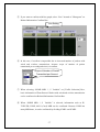
15. AP Setting Using Web Browser
① Open Web Browser. (Beyond IE 4.0 or Netscape 4.0)
② Enter AP’s IP Address on “Address” of the Web Browser.
Press [ENTER : ↵] key.
③ “Enter Network Password” window appears. Do not enter the User Name. Enter
the password. (The default value is “public”, and user can change the password
later)
Click [OK] button.
Notice : Capital•Small letter distinction is recommended for the password.
59
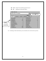
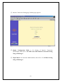
④ Internet Connection Setting page”(default page) appears.
⑤ Simple Configuration Mode is for Setting of Internet Connection
Environment, and refer to “10. ADSL and Cable Modem Connection Setting
Using AP Manager”.
⑥ Expert Mode is for Network Administration, and refer to “3. AP Basic Setting
Using AP Manager”.
60
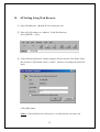
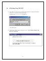
16. AP Setting Using TELNET
① Open “Run” on [Start] menu of desktop and notebook PC. Enter the IP Address
for Internet Connection as following Example.
Example) telnet ***.***.***.*** (IP Address )
Click [OK] button.
② Telnet order window appears, and please refer to “18. AP Basic Setting Using
RS-232C(COM Port)”
61
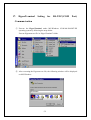
17.
HyperTerminal
Setting
for
RS-232C(COM
Port)
Commun-ication
① Execute the HyperTerminal under MS-Windows 95/98/Me/2000/NT/XP
operating system by following the steps below.
Execute Hypertrm.exe file in “HyperTerminal” folder.
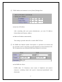
② After executing the Hypertrm.exe file, the following window will be displayed
on MS-Windows.
62
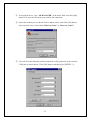
③ As displayed above, type “AP MANAGER” in the name field, and click [OK]
button. You can enter any name you wish for the connection.
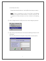
④ Select the modem port as shown in the window below, and click [OK] button.
(In most of the cases, select either “Direct to Com1” or “Direct to Com2”.)
⑤ You will view the following window and must set the properties of the selected
COM port as shown below. Click [OK] button, and then press [ENTER : ↵].
63
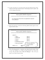
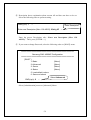
⑥ If all the steps above are executed correctly, then the following menu will be
displayed on the HyperTerminal window. The default password is “public”, and
user can change password later.
==================================================
Samsung SWL-4000AP Configuration
==================================================
To configure the Access Point, the password is required.
Enter password :
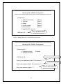
⑦ When the password is entered, the following [ROOT] menu appears on the
HyperTerminal window.
==================================================
Samsung SWL-4000AP Configuration
==================================================
[ ROOT ]
1. Basic
2. Advanced
3. Server
4. Status
5. Load default values
6. Save and reboot
CMD(t, p, h):
[Menu]
[Menu]
[Menu]
[Menu]
t: Top Menu([ROOT])
p: Previous Menu
h: Help
⑧ When AP setting procedure is completed, close HyperTerminal window. If this
is your first installation, on closing the HyperTerminal, you will get the
message “Do you want to save session AP Manager?”. Then, click [yes]
button to save HyperTerminal setting.
64
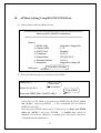
18. AP Basic Setting Using RS-232C(COM Port)
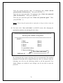
① Choose [Basic] menu on [ROOT] menu.
==================================================
Samsung SWL-4000AP Configuration
==================================================
[ Basic ]
1. ESSID (A/B)
2. Channel (A/B)
3. DHCP Client
4. IP Address
5. Subnet Mask
6. Gateway Address
7. Description
MagicLAN / MagicLAN
3/3
Disabled
10.0.0.2
255.255.255.0
10.0.0.1
MagicLAN 11Mbps AP
Enter Menu Number
CMD(t,p,h):
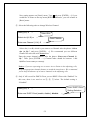
② Select the following order to set Wireless LAN ESSID.
CMD(t,p,h): 1
↵
Select slot {A, B}: a
Select Slot
↵
Enter ESSID
Enter new ESSID {Max. 32 ASCII}: AP_1
↵
Select slot (A or B) which is you want to set ESSID after the phrase “Select
slot {A, B}:”, and press [ENTER : ↵]. We recommend you use different
ESSID for each slots.
Enter the proper ESSID (strings up to 32 characters) on “Enter new ESSID
{Max. 32 ASCII}:”, and press [ENTER : ↵]. ESSID must consist of
alphabetic and numeric characters, excluding space and special characters.
(Capital•Small letter distinction)
65
New setting appears on [Basic] menu. Type t and press [ENTER : ↵] if you
would like to return to the top menu [ROOT]. Otherwise, you will remain in
[Basic] menu.
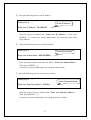
③ Select the following order to change Wireless Channel.
CMD(t,p,h): 2
↵
Select slot {A, B}: a
Select Slot
↵
Enter new Channel {1-14}: 5
Enter Channel
↵
Select slot (A or B) which is you want to set Channel after the phrase “Select
slot {A, B}:”, and press [ENTER : ↵]. We recommend you use different
Channel for each slots refer Notice blow.
Enter the proper channel number after the phrase “Enter new Channel {114}:”. Then, press [ENTER : ↵]. Channel index should be between 1 and
14(differs from country to country).
Notice : If you are operating two or more Access Points in the adjoining cells,
keep the appropriate channel distance to avoid the interference. We recommend
you to keep the distance of at least 4 channels in the adjoining cells.
④ Only if AP is used for DHCP Client, you set DHCP Client with “Enabled”. In
this case, there is no need to set ⑤, ⑥, ⑦ below. The default setting is
“Disabled”.
CMD(t,p,h): 3
Enter DHCP Client
Setting Selection
↵
Enter new DHCP Client {enable, disable}: disable
66
↵
⑤ Select the following order to set IP Address.
CMD(t,p,h): 4
↵
Enter IP Address
Enter new IP Address : 16.3.60.208
↵
Enter the proper IP address after “Enter new IP Address :”. Then, press
[ENTER : ↵]. Consult your system administrator for setting the proper value
of IP Address.
⑥
Select the following order to set Subnet Mask.
CMD(t,p,h): 5
↵
Enter Subnet Mask
Enter new Subnet Mask : 255.255.255.0
↵
Enter the proper subnet mask after the phrase “Enter new Subnet Mask :”.
Then, press [ENTER : ↵].
Consult your system administrator for setting the subnet mask.
⑦ Select the following order to set Gateway Address.
CMD(t,p,h): 6
↵
Enter Gateway Address
Enter new Gateway Address : 16.3.60.1
↵
Enter the proper Gateway Address after “Enter new Gateway Address :” .
Then, press [ENTER : ↵].
Consult your system administrator for setting the gateway address.
67
⑧ Description shows explanation about current AP and does not have to be set.
Select the following order to perform setting.
CMD(t,p,h): 7
↵
Enter Description
Enter new Description {Max. 128 ASCII}: 2Solt_AP ↵
Enter the proper Description after “Enter new Description {Max. 128
ASCII}:”. Then, press [ENTER : ↵].
⑨ If you want to change Password, select the following order on [ROOT] menu.
==================================================
Samsung SWL-4000AP Configuration
==================================================
[ ROOT ]
1. Basic
[Menu]
2. Advanced
[Menu]
3. Server
[Menu]
4. Status
[Menu]
5. Load default values
6. Save and reboot
Select Advanced
CMD(t,p,h): 2
↵
Select [Administration] menu on [Advanced] Menu.
68
==================================================
Samsung SWL-4000AP Configuration
==================================================
[ Advanced ]
1. Internet Connection
2. Wireless
3. Bridge
4. Access control
5. Administration
6. Upgrade FW via serial
CMD(t,p,h): 5
[Menu]
[Menu]
[Menu]
[Menu]
[Menu]
Select Administration
↵
Select “Change password” on [Administration] menu.
==================================================
Samsung SWL-3300AP Configuration
==================================================
[ Administration ]
1. Password activity
2. Change password
CMD (t,p,h): 2
Enabled
↵
Enter Current Password
Enter current password (Max. 30 characters):******
↵
Enter New Password
Enter new password (Max. 30 characters):******
Enter new password again:******
69
↵
↵
Confirm New Password
Enter the current password (Max. 30 characters) after “Enter current
password (Max. 30 characters):”. Then, press [ENTER : ↵].
Enter the new password (Max. 30 characters) after “Enter new password
(Max. 30 characters):” . Then, press [ENTER : ↵].
Enter the new password again after “Enter new password again:”. Then,
press [ENTER : ↵].
Notice : Please keep this password at a safe place or keep it where it may not
get lost.
⑩ You must select “Save and reboot” on [ROOT] menu, after changing the
appropriate parameters by entering the new values.
==================================================
Samsung SWL-4000AP Configuration
==================================================
[ ROOT ]
1. Basic
[Menu]
2. Advanced
[Menu]
3. Server
[Menu]
4. Status
[Menu]
5. Load default values
6. Save and reboot
Select Save and reboot
CMD(t,p,h): 6
↵
By selecting the above menu, rebooting will occur automatically. The modified
parameters of the AP will be changed effectively after it is rebooted. After the
rebooting, you will view the following window to ask the password. If no
further changes are needed in your settings, you do not need to enter the
password.
70
==================================================
Samsung SWL-4000AP Configuration
==================================================
To configure the Access Point, the password is required.
Enter password :
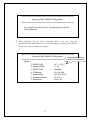
⑪ After following all the steps mentioned above, you can close the
HyperTerminal window if there is no need for change or setting. Select [Basic]
menu if you want to confirm the settings.
==================================================
Samsung SWL-4000AP Configuration
==================================================
Confirm Configuration
[ Basic ]
1. ESSID (A/B)
AP_1 / AP_2
2. Channel (A/B)
5 / 10
3. DHCP Client
Disabled
4. IP Address
16.3.60.208
5. Subnet Mask
255.255.255.0
6. Gateway Address
16.3.60.1
7. Description
2Slot_AP
71
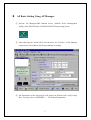
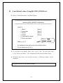
19. Load default values Using RS-232C(COM Port)
⑫ Select “Load default values” on [ROOT] menu
==================================================
Samsung SWL-4000AP Configuration
==================================================
[ ROOT ]
1. Basic
2. Advanced
3. Server
4. Status
5. Load default values
6. Save and reboot
CMD(t, p, h): 5
[Menu]
[Menu]
[Menu]
[Menu]
Select“Load
Load
Default values”
values
All configured items will be set to the default values.
Do you really want (y/n)? y
⑬ If you want to set default values, enter “y(yes)” after “Do you really want
(y/n)?” then, press [Enter:↵]. AP configuration will return to default setting.
⑭ If all the steps above are executed correctly, a following sentence will be
displayed.
All items were set to the default values.
72
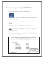
20. Firmware Upgrade Using RS-232C(COM Port)
① Click the “Hyperterminal icon” saved in hard disk of your PC’
② “Enter password” menu will be displayed on the HyperTerminal window. The
default password is “public”,
③ When the password is entered, [ROOT] menu appears on the HyperTerminal
window.
④ Downloaded the latest version of AP firmware in local disk of your PC
Notice: AP firmware corresponding to your AP can be downloaded in
MagicLAN home page.
⑤ After selecting [Advanced] menu on [ROOT] menu, select [Upgrade FW via
serial] menu on [Advanced] menu again
==================================================
Samsung SWL-4000AP Configuration
==================================================
[ Advanced ]
1. Radio
2. Encryption
3. HTTP Activity
4. Telnet Activity
5. Administration
6. Upgrade FW via serial
CMD(t,p,h): 6
↵
73
[Menu]
[Menu]
Enabled
Enabled
[Menu]
Select Upgrade FW
via serial
AP Firmware can be upgraded via serial using 1k-xmode protocol.
Power must be always on during the upgrade.
Do you really want to upgrade the firmware via serial ? (y/n):y ↵
Do you really want (y/n)? y
⑥ If you want to upgrade AP firmware, enter “y(yes)” after “Do you really want
to upgrade the firmware via serial ?” then, press [Enter:↵]. Enter “y(yes)”
again after “Do you really want (y/n)?”, then press [Enter:↵].
The following window will be displayed.
##################################################
AP will enter into the FIMWARE UPGRADE MODE
##################################################
>
===============================================
Boot firmware
(SST flash memory,0xBF)
2000.12.09
===============================================
Enter
Type command([go]: normal operating or [help]: help)
“apfirm”
CMD : apfirm ↵
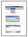
⑦ Enter the “apfirm” after “CMD: ” then, press [Enter ↵ ]
.
74
⑧ Select [transfer] menu on “Menu Bar” then, select “Send File“.
⑨ Click [Browse] button on the “Send File” window
⑩ After select the firmware image file on opened window, click [Open] button.
75
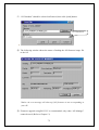
⑪ “1K Xmodem” should be selected on Protocol, then click [send] button.
1K Xmodem
⑫ The following window shows the status of loading the AP firmware image file
to the AP.
Notice: An error message will show up if AP firmware is not corresponding to
your AP.
⑬ Firmware upgrade using RS-232C is recommended, only when “AP Manager”
cannot be used. (Refer to Chapter 13)
76
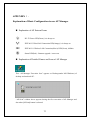
APPENDIX Ⅰ.
Explanation of Basic Configuration to use AP Manager
n Explanation of AP External Icons
DC 5V Power LED(Green), it is always on.
IEEE 802.3 Wired LAN Connection LED(Orange), it is always on.
IEEE 802.11 Wireless LAN Connection(Slot A) LED(Green), it blinks.
Status LED(Red) - firmware upgrade / error occur
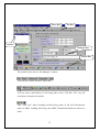
n Explanation of Detailed Names and Icons of AP Manager
This “AP Manager Execution Icon” appears on Desktop(under MS-Windows) of
desktop and notebook PC.
“AP Scan” window above appears during the first execution of AP Manager and
also when [AP Scan] button is selected.
77
Menu Bar
Tab Bar
List Box
Dialogue Box
Button Bar
The window above shows “AP Manager” window.
You can select menu from this “Menu Bar”.
You can select each function of AP setting tabs on this “Tab Bar”. The very left
icon shows currently selected tab.
This “LED icon” shows Sending and Receiving status of AP and Transmission
status of ADSL. Sending, Receiving, and ADSL Transmission Status are shown on
order.
78
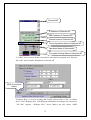
Selected AP
IP Address of Selected AP
MAC Address of Selected AP
Channel Index of Selected AP
Server Operation Status of Selected AP
Operation Mode of Selected AP
Encryption Setting Status of Selected AP
“List Box” shows Access Points connected to same network segment, and “Selected
AP’s Info” shows simple information of selected AP.
ADSL Connection
Status
“Dialogue Box” is area for reading and writing setting values of AP. As shown
above, each “Dialogue Box” with different information according to tab selected on
“Tab Bar” appears. “Dialogue Box” about [Basic] tab also shows ADSL
79
Connection Status.
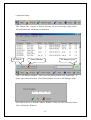
This “Button Bar” consists of buttons showing AP Scan, Entering setting values,
AP information and AP Manager information.
AP Search
Erase Window
AP Search Cycle
This is “AP Monitor Window” when you click [Mode] button from “Button Bar”. It
shows APs connected around. Click [Mode] button to return to AP Manager mode.
The window above is “Start IP Address Window” when you select [Search] button
from “AP Monitor Window”.
80
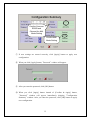
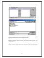
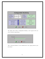
The window above shows “Configuration Summary”, and it appears when you
select [Confirm & Apply] button.
This is “Password Window” for user authentication. Click [Apply] button to open
this window.
81
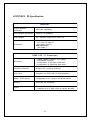
APPENDIX Ⅱ. Specification
General
Wireless Network
IEEE 802.11b(DSSS)
Architecture
Wired Network Architecture
Ethernet (10/100Mbps)
Power Adapter
90 ~ 265VAC 47/63 Hz to 5VDC 2A
Certifications
EMC Emission :
- FCC Part 15 Class B
- EN 55022 Class B
EMC Immunity :
EN 50082-1
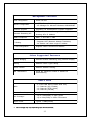
IEEE 802.11 Features
Data Rates
-
1Mbps, 2Mbps, 5.5Mbps, and 11Mbps
Auto-fallback features
Configuration of the Basic Data rates
Configuration of Supported Data rates
Long/Short Preamble
Supports the long/short preamble
Power save
Complies with IEEE 802.11b PS(Powersave)
Beacon, DTIM Interval
Configuration of the Beacon and DTIM Interval
Roaming
IEEE 802.11b Compliant
Security
- 64(40)/128 Bit WEP Encryption
- Supports up to 4 WEP Keys for 64(40) Bit WEP
82
Management Features
Local Configuration
Serial EIA-232
Remote Configuration
- HTTP, Telnet, SNMP supported
- AP Manager for Microsoft Windows 95/98/2000/NT
Firmware Upgrade
Upgrading via Serial/Ethernet Interface supported
Automatic Searching AP
Easy to search the AP using AP Manager without
knowing AP's IP Address
SNMP Compliance
MIB I, II and 802.11 MIB
IP Sharing
- Supports NAT (Network Address Translation)
- All stations can share single IP address
IP Auto-configuration
Supports DHCP Server/Client features
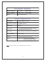
Other Supported Features
Wireless Bridging
Extends wireless networking using wireless bridging
Filtering
Ethernet Frame Type Filtering
Access Control
Ethernet Address Filtering
Max. Associations
Limits the maximum number of stations for
load-balancing
Radio Data
Radio
-
Receiver Sensitivity
-84dBm at 11Mbps
Cell Coverage*
- Up to 150m(500ft) in Open Space
- Up to 30m(100ft) in Office Environment
Output Power
Typical. 17dBm(70mW)
*
2.4 GHz ISM band (2.400-2.4835 GHz)
11 Channels (US, Canada)
13 Channels (ETSI, Korea)
14 Channels (JAPAN)
Cell Coverage may vary depending upon RF environment.
83
Environmental Information
Operating Temperature
℃ to 45℃
0℃
℉ to 113℉ )
(32℉
Storage Temperature
℃ to 70℃
℃
-25℃
℉ to 158℉
℉)
(-13℉
Humidity
95% Non-condensing
Physical Characteristics
WLAN Interface
PCMCIA Release 2.1 (3.3V)
Wired Network Connection
Type
10/100BaseT (RJ-45)
Serial Interface
EIA-232
Antenna Type
- Two Printed Antenna within wireless LAN card
- Optional External Dipole Antenna
LED Indicator
Power, Ethernet Link, Wireless A, and Wireless B
Power Consumption
DC 5V, 1.23A
Dimension
250 x 153 x 40 (mm)
(9.84" x 6.02" x 1.57")
(Except the External Dipole Antenna)
Weight
669g (1.47lb, Including the Power Adapter,
Excluding the Wireless LAN Card
and the External Dipole Antenna)
Notice : The specifications can be changed without a prior notice.
84
We value your feedback.
If you find errors or omissions in this manuscript, or if you can suggest ways to
improve its usefulness, we would be pleased to hear from you.
Please contact us at :
E-mail:
[email protected]
You can find the latest firmware, software, and documents at:
http://www.magiclan.com/