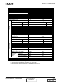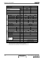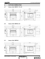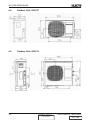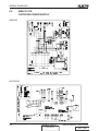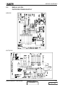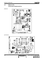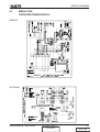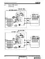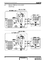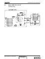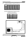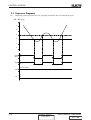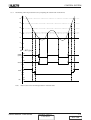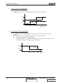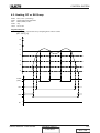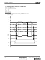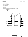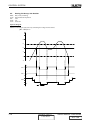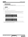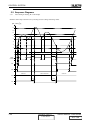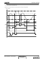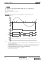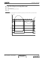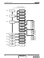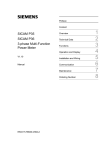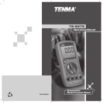
1
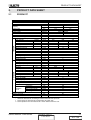
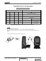
Service Manual
EMD series
Indoor Units
Outdoor Units
EMD 27
OU6-27
EMD 35
OU8-33
EMD 40
OU10-38
EMD 45
OU10-44
EMD 50
OU10-50
EMD 60
OU12-60
REFRIGERANT
R22
R407C
HEAT PUMP
COOLING ONLY
JULY 2005
CONTENT
DUCTED
LIST OF EFFECTIVE PAGES
LIST OF EFFECTIVE PAGES
Note: Changes in the pages are indicated by a “Revision#” in the footer of each effected page
(when none indicates no changes in the relevant page). All pages in the following list represent
effected/ non effected pages divided by chapters.
Dates of issue for original and changed pages are:
Original ....... 0 ........ July 2005
Total number of pages in this publication is 109 consisting of the following:
Page
No.
Revision
No. #
Title .......................
A ...........................
i .............................
1-1 - 1-2 ................
2-1 - 2-17 ..............
3-1 ........................
4-1 - 4-3 ................
5-1 - 5-7 ................
6-1 - 6-6 ................
7-1 - 7-33 ..............
8-1 - 8-2 ................
9-1 - 9-35 ..............
•
Page
No.
Revision
No. #
Page
No.
Revision
No. #
0
0
0
0
0
0
0
0
0
0
0
0
Zero in this column indicates an original page.
*Due to constant improvements please note that the data on this service manual can be modified with out notice.
**Photos are not contractual.
A
Revision Y05-01
CONTENT
Service Manual - EMD Series
DUCTED
TABLE OF CONTENTS
Table of Contents
1.
FEATURES ............................................................................................................1-1
2.
PRODUCT DATA SHEET ......................................................................................2-1
3.
RATING CONDITIONS ..........................................................................................3-1
4.
OUTLINE DIMENSIONS .......................................................................................4-1
5.
WIRING DIAGRAMS .............................................................................................5-1
6.
REFRIGERATION DIAGRAMS .............................................................................6-1
7.
CONTROL SYSTEM .............................................................................................7-1
8.
TROUBLESHOOTING ..........................................................................................8-1
9.
EXPLODED VIEWS AND SPARE PARTS LISTS .................................................9-1
Service Manual - EMD Series
Revision Y05-01
i
DUCTED
FEATURES
1.
FEATURES
MODES OF OPERATION , FUNCTIONS AND FEATURES
The air conditioner is based on a microcomputer control system with remote wall mounted LCD display and
control unit, programmed for the following modes and functions:
COOL
Cools, dehumidifies and filters the room air. Maintains desired site temperature.
HEAT
Heats and filters the air. Maintains desired site temperature.
AUTO
Automatically switches from COOLING to HEATING or from HEATING to
COOLING, maintaining the desired temperature according to the room conditions.
DRY
Dehumidifies and moderately cools the room. In DRY Mode the air conditioner
operates at an increased dehumidifying power. This function is recommended to
be used when temperature is rather cool but the humidity is high.
FAN
Recalculates and filters the room air. Maintains constant air movement in the
room.
AUTO FAN
The air conditioner automatically selects the FAN speed in accordance to the
room temperature. At the start, the unit operates at high fan speed. As the room
air gets closer to the desired temperature, the fan switches on a lower speed for
quieter operation.
HOT KEEP
In HEATING and in AUTO FAN, the fan will be turned off when the compressor is
not in operation and will not be restarted, unless the indoor coil reaches adequate
temperature. This HOT KEEP feature prevents uncomfortable cold air drafts.
AUTO FAN Is therefore, recommended to be used when the air conditioner is in
HEATING mode.
I FEEL
TIMER
SLEEP
Switches the temperature sensing point to the place where the remote control is
located (in normal operation the temperature sensor is located behind the intake
grille of the air conditioner). This function is designed to provide a personalized
environment by transmitting the temperature control information from where the
remote control is placed. The communication between the remote control and the
central control unit is done by infrared signal. When using this function, the remote
control should always be aimed without obstructions at the air conditioner.
Real time control and display, automatically turns the air conditioner ON or OFF
according to the time of day setting, ensuring comfort conditions before returning
home, without wasting electricity. It turns off the air conditioner automatically when
sleeping.
Designed to automatically reset the temperature setting. In COOLING mode the
temperature rises one degree centigrade after each consecutive hour, up to three
hours, from the start of the mode. In HEATING mode, the reverse occurs, the air
conditioner lowers its temperature one degree every hour. When in SLEEP Mode,
the operation will automatically turn off after seven hours. This function saves
energy when the air conditioner is operating during off hours.
Service Manual - EMD Series
Revision Y05-01
CONTENT
1-1
DUCTED
FEATURES
VERTICAL
AIR SWING
Not Applicable in Ducted unit.
AIR
DIRECTION
POSITIONING
Not Applicable in Ducted unit.
ROOM TEMP.
FILTER
INDICATION
BUZZER
ON UNIT
OPERATION
3-MIN
DELAYED
RUN
MEMORY
LOCK
1-2
Measures and displays room temperature.
Filter indicator on the indoor unit display is turned on when the filter requires
cleaning. After cleaning and reinstalling the filter, the system should be reset.
A soft buzzer will sound from the indoor unit display to indicate that a
command sent by the remote control has been accepted and stored in the
unit’s memory. This feature may be easily canceled by the user from the
display panel.
The air conditioner can be turned ON for COOLING or HEATING or be turned
OFF directly from the indoor unit display panel without the use of the remote
control.
The compressor is protected by a three minute delayed restart.
The microprocessor retains the last data entry whether or not the unit is plugged
in. Therefore, when the unit restarts after a power disruption or power failure, it will
resume operation in the same mode as before the power disruption.
Freezes the last operation setting on the remote control. When LOCK is activated,
the remote control will not be able to control the air conditioner.
Revision Y05-01
CONTENT
Service Manual - EMD Series
DUCTED
PRODUCT DATA SHEET
2.
PRODUCT DATA SHEET
2.1
R22/R407C
Model (Indoor & Outdoor)
Installation method
Characteristics
Capacity
OUTDOOR
INDOOR
Power input
COP
Power supply
Rated current
Starting current
Circuit breaker rating
Fan type & quantity
Fan speeds
H/ M/ L
Air flow *
H/ M/ L
External static pressure
Min-Max
Sound power level **
H/ M/ L
Sound pressure level ***
H/ M/ L
Moisture removal
Condensate drain tube I.D
Dimensions
W/ H / D
Weight
Package dimensions
W/ H / D
Package weight
Units per pallet
Stacking height
Refrigerant control
Compressor type
Fan type & quantity
Fan speeds
H/L
Air flow
H/L
Sound power level
H/L
Sound pressure level ***
H/L
Dimensions
W/ H / D
Weight
Package dimensions
W/ H / D
Package weight
Units per pallet
Stacking height
Refrigerant type
Charge / Distance
Additional charge per 1 meter
Liquid line
Connections
Suction line
between
Max. tubing length
units
Max. height difference
Operation control type
Heating elements
Others
Units
Btu/Hr
Kw
Kw
W/W
V/Hz/Ph
A
A
A
RPM
M³/Hr
Pa
dBa
dBa
Lt/Hr
mm
mm
Kg
mm
Kg
Units
Units
RPM
M³/Hr
dBa
dBa
mm
Kg
mm
Kg
Units
Units
Kg/ M
Grams
Inch
Inch
Meter
Meter
Kw
EMD 27 & OU6-27 RC R22
Ducted
Cooling
Heating
26600
27300
7.8
8.0
2.8
2.4
2.79
3.28
230V/50Hz/1PH
11.6
10.0
67
20
Centrifugal & 1
900
800
700
1800
1560
1300
25 - 70
68.2
65.5
61.3
54.3
51.5
48.5
1.7
19
785
400
595
32
825
425
610
34
8
4
Capillary tube
Scroll
Axial & 1
920
2350
69
62
900
580
340
64
985
640
410
67
9
3
R22
2.1/ 7.5
25
3/8
5/8
25
10
LCD Remote control
No
Crankcase heater (60W)
* Airflow in ducted units; according to nominal external static pressure.
** Sound power in ducted units is measured at air outlet side.
*** Sound pressure level is measured at 1-meter distance from the unit.
Service Manual - EMD Series
Revision Y05-01
CONTENT
2-1
DUCTED
PRODUCT DATA SHEET
Model (Indoor & Outdoor)
Installation method
Characteristics
Capacity
OUTDOOR
INDOOR
Power input
COP
Power supply
Rated current
Starting current
Circuit breaker rating
Fan type & quantity
Fan speeds
H/ M/ L
Air flow *
H/ M/ L
External static pressure
Min-Max
Sound power level **
H/ M/ L
Sound pressure level ***
H/ M/ L
Moisture removal
Condensate drain tube I.D
Dimensions
W/ H / D
Weight
Package dimensions
W/ H / D
Package weight
Units per pallet
Stacking height
Refrigerant control
Compressor type
Fan type & quantity
Fan speeds
H/L
Air flow
H/L
Sound power level
H/L
Sound pressure level ***
H/L
Dimensions
W/ H / D
Weight
Package dimensions
W/ H / D
Package weight
Units per pallet
Stacking height
Refrigerant type
Charge / Distance
Additional charge per 1 meter
Liquid line
Connections
Suction line
between
Max. tubing length
units
Max. height difference
Operation control type
Heating elements
Others
Units
Btu/Hr
Kw
Kw
W/W
V/Hz/Ph
A
A
A
RPM
M³/Hr
Pa
dBa
dBa
Lt/Hr
mm
mm
Kg
mm
Kg
Units
Units
RPM
M³/Hr
dBa
dBa
mm
Kg
mm
Kg
Units
Units
Kg/ M
Grams
Inch
Inch
Meter
Meter
Kw
EMD 27 & OU6-27 ST R22
Ducted
Cooling
26600
7.8
2.8
2.79
230V/50Hz/1PH
11.6
67
20
Centrifugal & 1
900
800
700
1800
1560
1300
25 - 70
68.2
65.5
61.3
54.3
51.5
48.5
1.7
19
785
400
595
32
825
425
610
34
8
4
Capillary tube
Scroll
Axial & 1
920
2350
69
62
900
580
340
64
985
640
410
67
9
3
R22
2.1/ 7.5
25
3/8
5/8
25
10
LCD Remote control
No
Crankcase heater (60W)
* Airflow in ducted units; according to nominal external static pressure.
** Sound power in ducted units is measured at air outlet side.
*** Sound pressure level is measured at 1-meter distance from the unit.
2-2
Revision Y05-01
CONTENT
Service Manual - EMD Series
DUCTED
PRODUCT DATA SHEET
Model (Indoor & Outdoor)
Installation method
Characteristics
Capacity
OUTDOOR
INDOOR
Power input
COP
Power supply
Rated current
Starting current
Circuit breaker rating
Fan type & quantity
Fan speeds
H/ M/ L
Air flow *
H/ M/ L
External static pressure
Min-Max
Sound power level **
H/ M/ L
Sound pressure level ***
H/ M/ L
Moisture removal
Condensate drain tube I.D
Dimensions
W/ H / D
Weight
Package dimensions
W/ H / D
Package weight
Units per pallet
Stacking height
Refrigerant control
Compressor type
Fan type & quantity
Fan speeds
H/L
Air flow
H/L
Sound power level
H/L
Sound pressure level ***
H/L
Dimensions
W/ H / D
Weight
Package dimensions
W/ H / D
Package weight
Units per pallet
Stacking height
Refrigerant type
Charge / Distance
Additional charge per 1 meter
Liquid line
Connections
Suction line
between
Max. tubing length
units
Max. height difference
Operation control type
Heating elements
Others
Units
Btu/Hr
Kw
Kw
W/W
V/Hz/Ph
A
A
A
RPM
M³/Hr
Pa
dBa
dBa
Lt/Hr
mm
mm
Kg
mm
Kg
Units
Units
RPM
M³/Hr
dBa
dBa
mm
Kg
mm
Kg
Units
Units
Kg/ M
Grams
Inch
Inch
Meter
Meter
Kw
EMD 35 & OU8-33 RC R22
Ducted
Cooling
Heating
32500
34800
9.5
10.1
3.3
2.9
2.87
3.53
230V/50Hz/1PH
14.4
12.3
76
20
Centrifugal & 1
890
800
680
1770
1570
1300
37 - 80
68.2
65.5
61.3
54.3
51.5
48.5
2.7
19
785
400
595
36
825
425
610
38
8
4
Capillary tube
Scroll
Axial & 1
850
3110
69
62
900
860
340
78
985
900
410
82
6
2
R22
2.33 / 7.5
25
3/8
5/8
30
10
LCD Remote control
No
Crankcase heater (60W)
* Airflow in ducted units; according to nominal external static pressure.
** Sound power in ducted units is measured at air outlet side.
*** Sound pressure level is measured at 1-meter distance from the unit.
Service Manual - EMD Series
Revision Y05-01
CONTENT
2-3
DUCTED
PRODUCT DATA SHEET
Model (Indoor & Outdoor)
Installation method
Characteristics
Capacity
OUTDOOR
INDOOR
Power input
COP
Power supply
Rated current
Starting current
Circuit breaker rating
Fan type & quantity
Fan speeds
H/ M/ L
Air flow *
H/ M/ L
External static pressure
Min-Max
Sound power level **
H/ M/ L
Sound pressure level ***
H/ M/ L
Moisture removal
Condensate drain tube I.D
Dimensions
W/ H / D
Weight
Package dimensions
W/ H / D
Package weight
Units per pallet
Stacking height
Refrigerant control
Compressor type
Fan type & quantity
Fan speeds
H/L
Air flow
H/L
Sound power level
H/L
Sound pressure level ***
H/L
Dimensions
W/ H / D
Weight
Package dimensions
W/ H / D
Package weight
Units per pallet
Stacking height
Refrigerant type
Charge / Distance
Additional charge per 1 meter
Liquid line
Connections
Suction line
between
Max. tubing length
units
Max. height difference
Operation control type
Heating elements
Others
Units
Btu/Hr
Kw
Kw
W/W
V/Hz/Ph
A
A
A
RPM
M³/Hr
Pa
dBa
dBa
Lt/Hr
mm
mm
Kg
mm
Kg
Units
Units
RPM
M³/Hr
dBa
dBa
mm
Kg
mm
Kg
Units
Units
Kg/ M
Grams
Inch
Inch
Meter
Meter
Kw
EMD 35 & OU8-33 ST R22
Ducted
Cooling
32500
9.5
3.3
2.87
230V/50Hz/1PH
14.4
76
20
Centrifugal & 1
890
800
680
1770
1570
1300
37 - 80
68.2
65.5
61.3
54.3
51.5
48.5
2.7
19
785
400
595
36
825
425
610
38
8
4
Capillary tube
Scroll
Axial & 1
850
3110
69
62
900
860
340
78
985
900
410
82
6
2
R22
2.33 / 7.5
25
3/8
5/8
30
10
LCD Remote control
No
Crankcase heater (60W)
* Airflow in ducted units; according to nominal external static pressure.
** Sound power in ducted units is measured at air outlet side.
*** Sound pressure level is measured at 1-meter distance from the unit.
2-4
Revision Y05-01
CONTENT
Service Manual - EMD Series
DUCTED
PRODUCT DATA SHEET
Model (Indoor & Outdoor)
Installation method
Characteristics
Capacity
OUTDOOR
INDOOR
Power input
COP
Power supply
Rated current
Starting current
Circuit breaker rating
Fan type & quantity
Fan speeds
H/ M/ L
Air flow *
H/ M/ L
External static pressure
Min-Max
Sound power level **
H/ M/ L
Sound pressure level ***
H/ M/ L
Moisture removal
Condensate drain tube I.D
Dimensions
W/ H / D
Weight
Package dimensions
W/ H / D
Package weight
Units per pallet
Stacking height
Refrigerant control
Compressor type
Fan type & quantity
Fan speeds
H/L
Air flow
H/L
Sound power level
H/L
Sound pressure level ***
H/L
Dimensions
W/ H / D
Weight
Package dimensions
W/ H / D
Package weight
Units per pallet
Stacking height
Refrigerant type
Charge / Distance
Additional charge per 1 meter
Liquid line
Connections
Suction line
between
Max. tubing length
units
Max. height difference
Operation control type
Heating elements
Others
Units
Btu/Hr
Kw
Kw
W/W
V/Hz/Ph
A
A
A
RPM
M³/Hr
Pa
dBa
dBa
Lt/Hr
mm
mm
Kg
mm
Kg
Units
Units
RPM
M³/Hr
dBa
dBa
mm
Kg
mm
Kg
Units
Units
Kg/ M
Grams
Inch
Inch
Meter
Meter
Kw
EMD 35T & OU8-33T RC R22
Ducted
Cooling
Heating
31800
34100
9.4
10.0
3.2
2.8
2.91
3.58
400V/50Hz/3N
3x9.1
3x8.1
36
3x16
Centrifugal & 1
890
800
680
1770
1570
1300
37 - 80
68.2
65.5
61.3
54.3
51.5
48.5
2.6
19
785
400
595
36
825
425
610
38
8
4
Capillary tube
Scroll
Axial & 1
850
3110
69
62
900
860
340
78
985
900
410
82
6
2
R22
2.33 / 7.5
25
3/8
5/8
30
10
LCD Remote control
No
Crankcase heater (60W), 3PH Protector
* Airflow in ducted units; according to nominal external static pressure.
** Sound power in ducted units is measured at air outlet side.
*** Sound pressure level is measured at 1-meter distance from the unit.
Service Manual - EMD Series
Revision Y05-01
CONTENT
2-5
DUCTED
PRODUCT DATA SHEET
Model (Indoor & Outdoor)
Installation method
Characteristics
Capacity
OUTDOOR
INDOOR
Power input
COP
Power supply
Rated current
Starting current
Circuit breaker rating
Fan type & quantity
Fan speeds
H/ M/ L
Air flow *
H/ M/ L
External static pressure
Min-Max
Sound power level **
H/ M/ L
Sound pressure level ***
H/ M/ L
Moisture removal
Condensate drain tube I.D
Dimensions
W/ H / D
Weight
Package dimensions
W/ H / D
Package weight
Units per pallet
Stacking height
Refrigerant control
Compressor type
Fan type & quantity
Fan speeds
H/L
Air flow
H/L
Sound power level
H/L
Sound pressure level ***
H/L
Dimensions
W/ H / D
Weight
Package dimensions
W/ H / D
Package weight
Units per pallet
Stacking height
Refrigerant type
Charge / Distance
Additional charge per 1 meter
Liquid line
Connections
Suction line
between
Max. tubing length
units
Max. height difference
Operation control type
Heating elements
Others
Units
Btu/Hr
Kw
Kw
W/W
V/Hz/Ph
A
A
A
RPM
M³/Hr
Pa
dBa
dBa
Lt/Hr
mm
mm
Kg
mm
Kg
Units
Units
RPM
M³/Hr
dBa
dBa
mm
Kg
mm
Kg
Units
Units
Kg/ M
Grams
Inch
Inch
Meter
Meter
Kw
EMD 35T & OU8-33T ST R22
Ducted
Cooling
31800
9.4
3.2
2.91
400V/50Hz/3N
3x9.1
36
3x16
Centrifugal & 1
890
800
680
1770
1570
1300
37 - 80
68.2
65.5
61.3
54.3
51.5
48.5
2.6
19
785
400
595
36
825
425
610
38
8
4
Capillary tube
Scroll
Axial & 1
850
3110
69
62
900
860
340
78
985
900
410
82
6
2
R22
2.33 / 7.5
25
3/8
5/8
30
10
LCD Remote control
No
Crankcase heater (60W), 3PH Protector
* Airflow in ducted units; according to nominal external static pressure.
** Sound power in ducted units is measured at air outlet side.
*** Sound pressure level is measured at 1-meter distance from the unit.
2-6
Revision Y05-01
CONTENT
Service Manual - EMD Series
DUCTED
PRODUCT DATA SHEET
Model (Indoor & Outdoor)
Installation method
Characteristics
Capacity
OUTDOOR
INDOOR
Power input
COP
Power supply
Rated current
Starting current
Circuit breaker rating
Fan type & quantity
Fan speeds
H/ M/ L
Air flow *
H/ M/ L
External static pressure
Min-Max
Sound power level **
H/ M/ L
Sound pressure level ***
H/ M/ L
Moisture removal
Condensate drain tube I.D
Dimensions
W/ H / D
Weight
Package dimensions
W/ H / D
Package weight
Units per pallet
Stacking height
Refrigerant control
Compressor type
Fan type & quantity
Fan speeds
H/L
Air flow
H/L
Sound power level
H/L
Sound pressure level ***
H/L
Dimensions
W/ H / D
Weight
Package dimensions
W/ H / D
Package weight
Units per pallet
Stacking height
Refrigerant type
Charge / Distance
Additional charge per 1 meter
Liquid line
Connections
Suction line
between
Max. tubing length
units
Max. height difference
Operation control type
Heating elements
Others
Units
Btu/Hr
Kw
Kw
W/W
V/Hz/Ph
A
A
A
RPM
M³/Hr
Pa
dBa
dBa
Lt/Hr
mm
mm
Kg
mm
Kg
Units
Units
RPM
M³/Hr
dBa
dBa
mm
Kg
mm
Kg
Units
Units
Kg/ M
Grams
Inch
Inch
Meter
Meter
Kw
EMD 40 & OU10-38 RC R22
Ducted
Cooling
Heating
37700
40200
11.0
11.6
3.9
3.5
2.82
3.32
230V/50Hz/1PH
17.9
15.9
114.0
25
Centrifugal & 1
1130
1020
830
1740
1530
1250
37- 80
70.8
67.1
62.8
54.1
50.6
49.2
3.6
19
785
400
595
36
825
425
610
38
8
4
Capillary tube
Scroll
Axial & 2
1125
4150
65
58
900
970
350
88.5
985
1020
435
93
6
2
R22
2.65 / 7.5
30
3/8
3/4
50
25
LCD Remote control
No
Crankcase heater (60W)
* Airflow in ducted units; according to nominal external static pressure.
** Sound power in ducted units is measured at air outlet side.
*** Sound pressure level is measured at 1-meter distance from the unit.
Service Manual - EMD Series
Revision Y05-01
CONTENT
2-7
DUCTED
PRODUCT DATA SHEET
Model (Indoor & Outdoor)
Installation method
Characteristics
Capacity
OUTDOOR
INDOOR
Power input
COP
Power supply
Rated current
Starting current
Circuit breaker rating
Fan type & quantity
Fan speeds
H/ M/ L
Air flow *
H/ M/ L
External static pressure
Min-Max
Sound power level **
H/ M/ L
Sound pressure level ***
H/ M/ L
Moisture removal
Condensate drain tube I.D
Dimensions
W/ H / D
Weight
Package dimensions
W/ H / D
Package weight
Units per pallet
Stacking height
Refrigerant control
Compressor type
Fan type & quantity
Fan speeds
H/L
Air flow
H/L
Sound power level
H/L
Sound pressure level ***
H/L
Dimensions
W/ H / D
Weight
Package dimensions
W/ H / D
Package weight
Units per pallet
Stacking height
Refrigerant type
Charge / Distance
Additional charge per 1 meter
Liquid line
Connections
Suction line
between
Max. tubing length
units
Max. height difference
Operation control type
Heating elements
Others
Units
Btu/Hr
Kw
Kw
W/W
V/Hz/Ph
A
A
A
RPM
M³/Hr
Pa
dBa
dBa
Lt/Hr
mm
mm
Kg
mm
Kg
Units
Units
RPM
M³/Hr
dBa
dBa
mm
Kg
mm
Kg
Units
Units
Kg/ M
Grams
Inch
Inch
Meter
Meter
Kw
EMD 40 & OU10-38 ST R22
Ducted
Cooling
37700
11.0
3.9
2.82
230V/50Hz/1PH
17.9
114.0
25
Centrifugal & 1
1130
1020
830
1740
1530
1250
37- 80
70.8
67.1
62.8
54.1
50.6
49.2
3.6
19
785
400
595
36
825
425
610
38
8
4
Capillary tube
Scroll
Axial & 2
1125
4150
65
58
900
970
350
88.5
985
1020
435
93
6
2
R22
2.65 / 7.5
30
3/8
3/4
50
25
LCD Remote control
No
Crankcase heater (60W)
* Airflow in ducted units; according to nominal external static pressure.
** Sound power in ducted units is measured at air outlet side.
*** Sound pressure level is measured at 1-meter distance from the unit.
2-8
Revision Y05-01
CONTENT
Service Manual - EMD Series
DUCTED
PRODUCT DATA SHEET
Model (Indoor & Outdoor)
Installation method
Characteristics
Capacity
OUTDOOR
INDOOR
Power input
COP
Power supply
Rated current
Starting current
Circuit breaker rating
Fan type & quantity
Fan speeds
H/ M/ L
Air flow *
H/ M/ L
External static pressure
Min-Max
Sound power level **
H/ M/ L
Sound pressure level ***
H/ M/ L
Moisture removal
Condensate drain tube I.D
Dimensions
W/ H / D
Weight
Package dimensions
W/ H / D
Package weight
Units per pallet
Stacking height
Refrigerant control
Compressor type
Fan type & quantity
Fan speeds
H/L
Air flow
H/L
Sound power level
H/L
Sound pressure level ***
H/L
Dimensions
W/ H / D
Weight
Package dimensions
W/ H / D
Package weight
Units per pallet
Stacking height
Refrigerant type
Charge / Distance
Additional charge per 1 meter
Liquid line
Connections
Suction line
between
Max. tubing length
units
Max. height difference
Operation control type
Heating elements
Others
Units
Btu/Hr
Kw
Kw
W/W
V/Hz/Ph
A
A
A
RPM
M³/Hr
Pa
dBa
dBa
Lt/Hr
mm
mm
Kg
mm
Kg
Units
Units
RPM
M³/Hr
dBa
dBa
mm
Kg
mm
Kg
Units
Units
Kg/ M
Grams
Inch
Inch
Meter
Meter
Kw
EMD 40T & OU10-38T RC R22
Ducted
Cooling
Heating
35800
38900
10.5
11.3
3.6
3.4
2.95
3.35
400V/50Hz/3N
3x9.8
3x9.3
48
3x16
Centrifugal & 1
1130
1020
830
1740
1530
1250
37- 80
70.8
67.1
62.8
54.1
50.6
49.2
3.5
19
785
400
595
36
825
425
610
38
8
4
Capillary tube
Scroll
Axial & 2
1125
4150
65
58
900
970
350
88.5
985
1020
435
93
6
2
R22
2.6 / 7.5
30
3/8
3/4
50
25
LCD Remote control
No
Crankcase heater (60W)
* Airflow in ducted units; according to nominal external static pressure.
** Sound power in ducted units is measured at air outlet side.
*** Sound pressure level is measured at 1-meter distance from the unit.
Service Manual - EMD Series
Revision Y05-01
CONTENT
2-9
DUCTED
PRODUCT DATA SHEET
Model (Indoor & Outdoor)
Installation method
Characteristics
Capacity
OUTDOOR
INDOOR
Power input
COP
Power supply
Rated current
Starting current
Circuit breaker rating
Fan type & quantity
Fan speeds
H/ M/ L
Air flow *
H/ M/ L
External static pressure
Min-Max
Sound power level **
H/ M/ L
Sound pressure level ***
H/ M/ L
Moisture removal
Condensate drain tube I.D
Dimensions
W/ H / D
Weight
Package dimensions
W/ H / D
Package weight
Units per pallet
Stacking height
Refrigerant control
Compressor type
Fan type & quantity
Fan speeds
H/L
Air flow
H/L
Sound power level
H/L
Sound pressure level ***
H/L
Dimensions
W/ H / D
Weight
Package dimensions
W/ H / D
Package weight
Units per pallet
Stacking height
Refrigerant type
Charge / Distance
Additional charge per 1 meter
Liquid line
Connections
Suction line
between
Max. tubing length
units
Max. height difference
Operation control type
Heating elements
Others
Units
Btu/Hr
Kw
Kw
W/W
V/Hz/Ph
A
A
A
RPM
M³/Hr
Pa
dBa
dBa
Lt/Hr
mm
mm
Kg
mm
Kg
Units
Units
RPM
M³/Hr
dBa
dBa
mm
Kg
mm
Kg
Units
Units
Kg/ M
Grams
Inch
Inch
Meter
Meter
Kw
EMD 40T & OU10-38T ST R22
Ducted
Cooling
35800
10.5
3.6
2.95
400V/50Hz/3N
3x9.8
48
3x16
Centrifugal & 1
1130
1020
830
1740
1530
1250
37- 80
70.8
67.1
62.8
54.1
50.6
49.2
3.5
19
785
400
595
36
825
425
610
38
8
4
Capillary tube
Scroll
Axial & 2
1125
4150
65
58
900
970
350
88.5
985
1020
435
93
6
2
R22
2.6 / 7.5
30
3/8
3/4
50
25
LCD Remote control
No
Crankcase heater (60W)
* Airflow in ducted units; according to nominal external static pressure.
** Sound power in ducted units is measured at air outlet side.
*** Sound pressure level is measured at 1-meter distance from the unit.
2-10
Revision Y05-01
CONTENT
Service Manual - EMD Series
DUCTED
PRODUCT DATA SHEET
Model (Indoor & Outdoor)
Installation method
Characteristics
Capacity
OUTDOOR
INDOOR
Power input
COP
Power supply
Rated current
Starting current
Circuit breaker rating
Fan type & quantity
Fan speeds
H/ M/ L
Air flow *
H/ M/ L
External static pressure
Min-Max
Sound power level **
H/ M/ L
Sound pressure level ***
H/ M/ L
Moisture removal
Condensate drain tube I.D
Dimensions
W/ H / D
Weight
Package dimensions
W/ H / D
Package weight
Units per pallet
Stacking height
Refrigerant control
Compressor type
Fan type & quantity
Fan speeds
H/L
Air flow
H/L
Sound power level
H/L
Sound pressure level ***
H/L
Dimensions
W/ H / D
Weight
Package dimensions
W/ H / D
Package weight
Units per pallet
Stacking height
Refrigerant type
Charge / Distance
Additional charge per 1 meter
Liquid line
Connections
Suction line
between
Max. tubing length
units
Max. height difference
Operation control type
Heating elements
Others
Units
Btu/Hr
Kw
Kw
W/W
V/Hz/Ph
A
A
A
RPM
M³/Hr
Pa
dBa
dBa
Lt/Hr
mm
mm
Kg
mm
Kg
Units
Units
RPM
M³/Hr
dBa
dBa
mm
Kg
mm
Kg
Units
Units
Kg/ M
Grams
Inch
Inch
Meter
Meter
Kw
EMD 45T & OU10-44T RC R22
Ducted
Cooling
Heating
43400
45000
12.7
13.0
4.8
4.0
2.64
3.24
400V/50Hz/3N
3x13.1
3x11.1
61.8
3x16
Centrifugal & 1
1000
900
800
2180
1960
1740
50 - 100
73.2
70.1
66.1
56.3
54.0
51.7
3.8
19
1040
400
595
42
1100
435
620
45
8
2
Capillary tube
Scroll
Axial & 2
1125
4150
65
58
900
970
350
88.5
985
1020
435
93
6
2
R22
2.75 / 7.5
30
3/8
3/4
50
25
LCD Remote control
No
Crankcase heater (60W)
* Airflow in ducted units; according to nominal external static pressure.
** Sound power in ducted units is measured at air outlet side.
*** Sound pressure level is measured at 1-meter distance from the unit.
Service Manual - EMD Series
Revision Y05-01
CONTENT
2-11
DUCTED
PRODUCT DATA SHEET
Model (Indoor & Outdoor)
Installation method
Characteristics
Capacity
OUTDOOR
INDOOR
Power input
COP
Power supply
Rated current
Starting current
Circuit breaker rating
Fan type & quantity
Fan speeds
H/ M/ L
Air flow *
H/ M/ L
External static pressure
Min-Max
Sound power level **
H/ M/ L
Sound pressure level ***
H/ M/ L
Moisture removal
Condensate drain tube I.D
Dimensions
W/ H / D
Weight
Package dimensions
W/ H / D
Package weight
Units per pallet
Stacking height
Refrigerant control
Compressor type
Fan type & quantity
Fan speeds
H/L
Air flow
H/L
Sound power level
H/L
Sound pressure level ***
H/L
Dimensions
W/ H / D
Weight
Package dimensions
W/ H / D
Package weight
Units per pallet
Stacking height
Refrigerant type
Charge / Distance
Additional charge per 1 meter
Liquid line
Connections
Suction line
between
Max. tubing length
units
Max. height difference
Operation control type
Heating elements
Others
Units
Btu/Hr
Kw
Kw
W/W
V/Hz/Ph
A
A
A
RPM
M³/Hr
Pa
dBa
dBa
Lt/Hr
mm
mm
Kg
mm
Kg
Units
Units
RPM
M³/Hr
dBa
dBa
mm
Kg
mm
Kg
Units
Units
Kg/ M
Grams
Inch
Inch
Meter
Meter
Kw
EMD 45T & OU10-44T ST R22
Ducted
Cooling
43400
12.7
4.8
2.64
400V/50Hz/3N
3x13.1
61.8
3x16
Centrifugal & 1
1000
900
800
2180
1960
1740
50 - 100
73.2
70.1
66.1
56.3
54.0
51.7
3.8
19
1040
400
595
42
1100
435
620
45
8
2
Capillary tube
Scroll
Axial & 2
1125
4150
65
58
900
970
350
88.5
985
1020
435
93
6
2
R22
2.75 / 7.5
30
3/8
3/4
50
25
LCD Remote control
No
Crankcase heater (60W)
* Airflow in ducted units; according to nominal external static pressure.
** Sound power in ducted units is measured at air outlet side.
*** Sound pressure level is measured at 1-meter distance from the unit.
2-12
Revision Y05-01
CONTENT
Service Manual - EMD Series
DUCTED
PRODUCT DATA SHEET
Model (Indoor & Outdoor)
Installation method
Characteristics
Capacity
OUTDOOR
INDOOR
Power input
COP
Power supply
Rated current
Starting current
Circuit breaker rating
Fan type & quantity
Fan speeds
H/ M/ L
Air flow *
H/ M/ L
External static pressure
Min-Max
Sound power level **
H/ M/ L
Sound pressure level ***
H/ M/ L
Moisture removal
Condensate drain tube I.D
Dimensions
W/ H / D
Weight
Package dimensions
W/ H / D
Package weight
Units per pallet
Stacking height
Refrigerant control
Compressor type
Fan type & quantity
Fan speeds
H/L
Air flow
H/L
Sound power level
H/L
Sound pressure level ***
H/L
Dimensions
W/ H / D
Weight
Package dimensions
W/ H / D
Package weight
Units per pallet
Stacking height
Refrigerant type
Charge / Distance
Additional charge per 1 meter
Liquid line
Connections
Suction line
between
Max. tubing length
units
Max. height difference
Operation control type
Heating elements
Others
Units
Btu/Hr
Kw
Kw
W/W
V/Hz/Ph
A
A
A
RPM
M³/Hr
Pa
dBa
dBa
Lt/Hr
mm
mm
Kg
mm
Kg
Units
Units
RPM
M³/Hr
dBa
dBa
mm
Kg
mm
Kg
Units
Units
Kg/ M
Grams
Inch
Inch
Meter
Meter
Kw
EMD 50T & OU10-50T RC R22
Ducted
Cooling
Heating
47500
51000
13.9
14.9
5.1
4.5
2.74
3.30
400V/50Hz/3N
3x14.7
3x13.2
65.5
3x16
Centrifugal & 1
1030
930
820
2400
2160
1910
50 - 100
73.2
70.1
66.1
56.3
54.0
51.7
4.8
19
1040
400
595
43
1100
435
620
46
8
2
Capillary tube
Scroll
Axial & 2
1220
955
4345
3400
69
63
62
56
900
970
350
90.5
985
1020
435
95
6
2
R22
4.2 / 7.5
30
3/8
3/4
50
25
LCD Remote control
No
Crankcase heater (60W)
* Airflow in ducted units; according to nominal external static pressure.
** Sound power in ducted units is measured at air outlet side.
*** Sound pressure level is measured at 1-meter distance from the unit.
Service Manual - EMD Series
Revision Y05-01
CONTENT
2-13
DUCTED
PRODUCT DATA SHEET
Model (Indoor & Outdoor)
Installation method
Characteristics
Capacity
OUTDOOR
INDOOR
Power input
COP
Power supply
Rated current
Starting current
Circuit breaker rating
Fan type & quantity
Fan speeds
H/ M/ L
Air flow *
H/ M/ L
External static pressure
Min-Max
Sound power level **
H/ M/ L
Sound pressure level ***
H/ M/ L
Moisture removal
Condensate drain tube I.D
Dimensions
W/ H / D
Weight
Package dimensions
W/ H / D
Package weight
Units per pallet
Stacking height
Refrigerant control
Compressor type
Fan type & quantity
Fan speeds
H/L
Air flow
H/L
Sound power level
H/L
Sound pressure level ***
H/L
Dimensions
W/ H / D
Weight
Package dimensions
W/ H / D
Package weight
Units per pallet
Stacking height
Refrigerant type
Charge / Distance
Additional charge per 1 meter
Liquid line
Connections
Suction line
between
Max. tubing length
units
Max. height difference
Operation control type
Heating elements
Others
Units
Btu/Hr
Kw
Kw
W/W
V/Hz/Ph
A
A
A
RPM
M³/Hr
Pa
dBa
dBa
Lt/Hr
mm
mm
Kg
mm
Kg
Units
Units
RPM
M³/Hr
dBa
dBa
mm
Kg
mm
Kg
Units
Units
Kg/ M
Grams
Inch
Inch
Meter
Meter
Kw
EMD 50T & OU10-50T ST R22
Ducted
Cooling
47500
13.9
5.1
2.74
400V/50Hz/3N
3x14.7
65.5
3x16
Centrifugal & 1
1030
930
820
2400
2160
1910
50 - 100
73.2
70.1
66.1
56.3
54.0
51.7
4.8
19
1040
400
595
43
1100
435
620
46
8
2
Capillary tube
Scroll
Axial & 2
1220
955
4345
3400
69
63
62
56
900
970
350
90.5
985
1020
435
95
6
2
R22
4.2 / 7.5
30
3/8
3/4
50
25
LCD Remote control
No
Crankcase heater (60W)
* Airflow in ducted units; according to nominal external static pressure.
** Sound power in ducted units is measured at air outlet side.
*** Sound pressure level is measured at 1-meter distance from the unit.
2-14
Revision Y05-01
CONTENT
Service Manual - EMD Series
DUCTED
PRODUCT DATA SHEET
Model (Indoor & Outdoor)
Installation method
Characteristics
Capacity
OUTDOOR
INDOOR
Power input
COP
Power supply
Rated current
Starting current
Circuit breaker rating
Fan type & quantity
Fan speeds
H/ M/ L
Air flow *
H/ M/ L
External static pressure
Min-Max
Sound power level **
H/ M/ L
Sound pressure level ***
H/ M/ L
Moisture removal
Condensate drain tube I.D
Dimensions
W/ H / D
Weight
Package dimensions
W/ H / D
Package weight
Units per pallet
Stacking height
Refrigerant control
Compressor type
Fan type & quantity
Fan speeds
H/L
Air flow
H/L
Sound power level
H/L
Sound pressure level ***
H/L
Dimensions
W/ H / D
Weight
Package dimensions
W/ H / D
Package weight
Units per pallet
Stacking height
Refrigerant type
Charge / Distance
Additional charge per 1 meter
Liquid line
Connections
Suction line
between
Max. tubing length
units
Max. height difference
Operation control type
Heating elements
Others
Units
Btu/Hr
Kw
Kw
W/W
V/Hz/Ph
A
A
A
RPM
M³/Hr
Pa
dBa
dBa
Lt/Hr
mm
mm
Kg
mm
Kg
Units
Units
RPM
M³/Hr
dBa
dBa
mm
Kg
mm
Kg
Units
Units
Kg/ M
Grams
Inch
Inch
Meter
Meter
Kw
EMD 50T & OU10-50T RC R407C
Ducted
Cooling
Heating
45700
51500
13.4
15.1
5.4
5.6
2.5
2.7
400V/50Hz/3N
3x15.0
3x15.3
57
3x16
Centrifugal & 1
1030
930
820
2400
2160
1910
50 - 100
73.2
70.1
66.1
56.3
54.0
51.7
4.9
19
1040
400
595
43
1100
435
620
46
8
2
Capillary tube
Scroll
Axial & 2
1220
955
4345
3400
69
63
62
56
900
970
350
90.5
985
1020
435
95
6
2
R407C
4.15 / 7.5
30
3/8
3/4
50
25
LCD Remote control
No
Crankcase heater (60W), 3PH Protector
* Airflow in ducted units; according to nominal external static pressure.
** Sound power in ducted units is measured at air outlet side.
*** Sound pressure level is measured at 1-meter distance from the unit.
Service Manual - EMD Series
Revision Y05-01
CONTENT
2-15
DUCTED
PRODUCT DATA SHEET
Model (Indoor & Outdoor)
Installation method
Characteristics
Capacity
OUTDOOR
INDOOR
Power input
COP
Power supply
Rated current
Starting current
Circuit breaker rating
Fan type & quantity
Fan speeds
H/ M/ L
Air flow *
H/ M/ L
External static pressure
Min-Max
Sound power level **
H/ M/ L
Sound pressure level ***
H/ M/ L
Moisture removal
Condensate drain tube I.D
Dimensions
W/ H / D
Weight
Package dimensions
W/ H / D
Package weight
Units per pallet
Stacking height
Refrigerant control
Compressor type
Fan type & quantity
Fan speeds
H/L
Air flow
H/L
Sound power level
H/L
Sound pressure level ***
H/L
Dimensions
W/ H / D
Weight
Package dimensions
W/ H / D
Package weight
Units per pallet
Stacking height
Refrigerant type
Charge / Distance
Additional charge per 1 meter
Liquid line
Connections
Suction line
between
Max. tubing length
units
Max. height difference
Operation control type
Heating elements
Others
Units
Btu/Hr
Kw
Kw
W/W
V/Hz/Ph
A
A
A
RPM
M³/Hr
Pa
dBa
dBa
Lt/Hr
mm
mm
Kg
mm
Kg
Units
Units
RPM
M³/Hr
dBa
dBa
mm
Kg
mm
Kg
Units
Units
Kg/ M
Grams
Inch
Inch
Meter
Meter
Kw
EMD 60T & OU12-60T RC R22
Ducted
Cooling
Heating
55000
56900
16.1
16.5
5.9
5.2
2.74
3.16
400V/50Hz/3N
3x16.3
3x14.8
74
3x20
Centrifugal & 1
1000
840
700
2950
2480
2065
50 - 110
71.8
68.9
62.3
60.2
55.7
51.5
4.8
19
1140
400
680
46
1195
440
730
50
8
4
Capillary tube
Scroll
Axial & 2
825
560
4850
3300
70
62.0
60.4
53.7
900
1255
350
110
985
1395
435
120
1
1
R22
5000 / 7.5
40
1/2
7/8
50
25
LCD Remote control
No
Crankcase heater (60W)
* Airflow in ducted units; according to nominal external static pressure.
** Sound power in ducted units is measured at air outlet side.
*** Sound pressure level is measured at 1-meter distance from the unit.
2-16
Revision Y05-01
CONTENT
Service Manual - EMD Series
DUCTED
PRODUCT DATA SHEET
Model (Indoor & Outdoor)
Installation method
Characteristics
Capacity
OUTDOOR
INDOOR
Power input
COP
Power supply
Rated current
Starting current
Circuit breaker rating
Fan type & quantity
Fan speeds
H/ M/ L
Air flow *
H/ M/ L
External static pressure
Min-Max
Sound power level **
H/ M/ L
Sound pressure level ***
H/ M/ L
Moisture removal
Condensate drain tube I.D
Dimensions
W/ H / D
Weight
Package dimensions
W/ H / D
Package weight
Units per pallet
Stacking height
Refrigerant control
Compressor type
Fan type & quantity
Fan speeds
H/L
Air flow
H/L
Sound power level
H/L
Sound pressure level ***
H/L
Dimensions
W/ H / D
Weight
Package dimensions
W/ H / D
Package weight
Units per pallet
Stacking height
Refrigerant type
Charge / Distance
Additional charge per 1 meter
Liquid line
Connections
Suction line
between
Max. tubing length
units
Max. height difference
Operation control type
Heating elements
Others
Units
Btu/Hr
Kw
Kw
W/W
V/Hz/Ph
A
A
A
RPM
M³/Hr
Pa
dBa
dBa
Lt/Hr
mm
mm
Kg
mm
Kg
Units
Units
RPM
M³/Hr
dBa
dBa
mm
Kg
mm
Kg
Units
Units
Kg/ M
Grams
Inch
Inch
Meter
Meter
Kw
EMD 60T & OU12-60T RC R407C
Ducted
Cooling
Heating
51860
61400
15.2
18.0
6.0
6.3
2.52
2.86
400V/50Hz/3N
3x16.4
3x16.8
74
3x20
Centrifugal & 1
1000
840
700
2950
2480
2065
50 - 110
71.8
68.9
62.3
60.2
55.7
51.5
4.7
19
1140
400
680
46
1195
440
730
50
8
4
Capillary tube
Scroll
Axial & 2
825
560
4850
3300
70
62.0
60.4
53.7
900
1255
350
110
985
1395
435
120
1
1
R407C
4550 / 7.5
40
1/2
7/8
50
25
LCD Remote control
No
Crankcase heater (60W)
* Airflow in ducted units; according to nominal external static pressure.
** Sound power in ducted units is measured at air outlet side.
*** Sound pressure level is measured at 1-meter distance from the unit.
Service Manual - EMD Series
Revision Y05-01
CONTENT
2-17
DUCTED
RATING CONDITIONS
3.
RATING CONDITIONS
NOTES:
1. Rating conditions ISO/CD 13253R
Cooling: indoor: 27qC (80qF) DB 19qC (66qF) WB
Outdoor: 35qC (95qF) DB
Heating: indoor: 20qC (68qF) DB
Outdoor: 7qC (45qF) DB 6qC (43qF) WB
Refrigerant tubing length (one way) 7.5m (24.6 ft)
2. Guaranteed operating range:
Cooling
Heating
Voltage
Upper limit
Lower limit
Upper limit
Indoor
32qC DB, 23qC WB
21qC DB, 15qC WB
27qC DB
Lower limit
20qC DB
1 PH
3 PH
Service Manual - EMD Series
Outdoor
46qC DB
21qC DB
24qC DB, 18qC WB
-5qC DB, -6qC WB (For R22)
-9qC DB, -10qC WB (For R407C)
198 – 242 V
360 – 440 V
Revision Y05-01
CONTENT
3-1
DUCTED
OUTLINE DIMENSIONS
4.
OUTLINE DIMENSIONS
4.1
Indoor Unit: EMD 27, 35, 40
600
4.2
Indoor Unit: EMD 45, 50
600
4.3
Indoor Unit: EMD 60
Service Manual - EMD Series
Revision Y05-01
CONTENT
4-1
DUCTED
OUTLINE DIMENSIONS
4.4
Outdoor Unit: OU6-27
4.5
Outdoor Unit: OU8-33
4-2
Revision Y05-01
CONTENT
Service Manual - EMD Series
DUCTED
OUTLINE DIMENSIONS
4.6
Outdoor Unit: OU10-38/45/50
4.7
Outdoor Unit: OU12-60
Service Manual - EMD Series
Revision Y05-01
CONTENT
4-3
DUCTED
WIRING DIAGRAMS
5.
WIRING DIAGRAMS
5.1
EMD 27 1PH
INDOOR POWER SUPPLY
INDOOR
OUTDOOR
Service Manual - EMD Series
Revision Y05-01
CONTENT
5-1
DUCTED
WIRING DIAGRAMS
5.2
EMD 35 1PH
OUTDOOR POWER SUPPLY
INDOOR
OUTDOOR
5-2
Revision Y05-01
CONTENT
Service Manual - EMD Series
DUCTED
WIRING DIAGRAMS
5,3
EMD 35 3PH
OUTDOOR POWER SUPPLY
INDOOR
OUTDOOR
Service Manual - EMD Series
Revision Y05-01
CONTENT
5-3
DUCTED
WIRING DIAGRAMS
5.4
EMD 40 1PH
OUTDOOR POWER SUPPLY
I
INDOOR
OUTDOOR
5-4
Revision Y05-01
CONTENT
Service Manual - EMD Series
DUCTED
WIRING DIAGRAMS
5.5
EMD 40, 45 3PH
OUTDOOR POWER SUPPLY
INDOOR
OUTDOOR
Service Manual - EMD Series
Revision Y05-01
CONTENT
5-5
DUCTED
WIRING DIAGRAMS
5,6
EMD 50 3PH
OUTDOOR POWER SUPPLY
INDOOR
OUTDOOR
5-6
Revision Y05-01
CONTENT
Service Manual - EMD Series
DUCTED
WIRING DIAGRAMS
5,7
EMD 60 3PH
OUTDOOR POWER SUPPLY
INDOOR
OUTDOOR
Service Manual - EMD Series
Revision Y05-01
CONTENT
5-7
DUCTED
REFRIGERATION DIAGRAMS
6.
REFRIGERATION DIAGRAMS
6.1
Model: EMD 27 RC
Heat Pump
Service Manual - EMD Series
Revision Y05-01
CONTENT
6-1
DUCTED
REFRIGERATION DIAGRAMS
6.2
Model: EMD 35 RC
Heat Pump
6-2
Revision Y05-01
CONTENT
Service Manual - EMD Series
DUCTED
REFRIGERATION DIAGRAMS
6.3
Models: EMD 27, 35 ST
Cooling Only
Service Manual - EMD Series
Revision Y05-01
CONTENT
6-3
DUCTED
REFRIGERATION DIAGRAMS
6.4
Models: EMD 40, 45, 50, 60 RC
Heat Pump
6-4
Revision Y05-01
CONTENT
Service Manual - EMD Series
DUCTED
REFRIGERATION DIAGRAMS
6.5
Model: EMD 40, 45, 50 ST
Cooling Only
Service Manual - EMD Series
Revision Y05-01
CONTENT
6-5
DUCTED
REFRIGERATION DIAGRAMS
6.6
Additional Refrigerant Charge (R 22, R407C gr.)
MODEL
EMD 27
EMD 35
EMD 40
EMD 45
EMD 50
EMD 60
REFRIGERANT TUBING LENGTH (ONE WAY)
10m
60
60
75
75
15m
185
185
225
225
25m
435
435
525
525
30m
560
675
675
50m
1275
1275
75
100
225
300
525
700
675
900
1275
1700
MAXIMUM REFRIGARANT TUBING LENGTH
AND HEIGHT DIFFERENCE
MODEL
LENGTH (m)
(A)
HEIGTH
DIFFERENCE (m)
EMD 27
EMD 35
EMD 40
EMD 45
EMD 50
EMD 60
25
30
50
50
50
50
10
10
25
25
25
25
* THE INDOOR UNIT CAN BE ABOVE OR BELOW THE OUTDOOR UNIT.
6-6
Revision Y05-01
CONTENT
Service Manual - EMD Series
DUCTED
CONTROL SYSTEM
7.
CONTROL SYSTEM
Instructions for
Electronic Control Service Package
INTRODUCTON
The electronic control package is designated for service and is common for the following group
of air-conditioners.
1. ST/RC group
-
Cooling only / Cooling and Heating by heat pump.
2. SH group
-
Cooling and Heating by heat pump and supplementary heater.
3. RH group
-
Cooling and Heating by heaters only.
Before installation , be sure that you select and set for the right group .
PACKAGE CONTENT
The following should be included in the electronic control service package:
- Controller designated for service
- Model plug
MODEL PLUG SETTINGS
Before installation, make sure to set the model plug to conform with the suitable group.
GROUP
ST / RC
SH
RH
Service Manual - EMD Series
J6 Setting
open
closed
closed
Revision Y05-01
CONTENT
J2 Setting
open
open
closed
7-1
DUCTED
CONTROL
SYSTEM
DUCTED
SPLIT
A.C
CONTROLS, MAIN P.C.B
8
POWER CONTROLLE
POWE
OLLER
REV. 01 03/2004
7-2
Revision Y05-01
CONTENT
SERIES: EMD
PG. 8-2
Service Manual - EMD Series
DUCTED
CONTROL SYSTEM
FIG.4
ELECTRICAL ASSEMBLY – EMD
FOR COMPONENTS DESCRIPTION AND CATALOG NUMBERS REFER
TO SPARE PARTS LIST FOR THE RELEVANT PRODUCT NO.
REV. 01 03/2004
Service Manual - EMD Series
Revision Y05-01
CONTENT
SERIES: EMD
PG. 12- 14
7-3
DUCTED
CONTROL SYSTEM
GANG BOARD
DISPLAY BOARD
7-4
Revision Y05-01
CONTENT
Service Manual - EMD Series
DUCTED
CONTROL SYSTEM
CONFIGURATION OF THE APPLIANCE
REMOTE CONTROL DIP SWITCH SETTING
SETTING SWITCH STATUS
SW. NO. 1
OFF
ON
OFF
ON
_
_
_
_
SW. NO. 2
OFF
OFF
ON
ON
_
_
_
_
DEFINITION
SW. NO. 3
SW. NO.4
RC3
RC4
_
_
RC-ALL MODES OF OPERATION
_
_
STD-COOL, FAN, DRY, ACTIVE
_
_
HEAT-COOL, FAN, DRY, ACTIVE
_
_
AUTO FAN (AF)
OFF
_
TEMP. DISPLAY IN qC DEGREES
VERTICAL SWING ONLY
ON
_
TEMP. DISPLAY IN qF DEGREES
HORIZONTAL & VERTICAL SWING
FUNCTIONS TOGETHER
_
OFF
TIMER & CLOCK 12 H AM, PM
DISABLE LCD &
KEY ILLUMINATION
_
ON
TIMER & CLOCK 24 H
ENABLE LCD &
KEY ILLUMINATION
RESET OPERATION - Press at the same time the 4 buttons :“CLEAR “, “SET” ,
"HR +”, “HR -” for 5 seconds
LEGEND:
SW1, SW2 - SELECTION OF RC/ST
SW3 - SELECTION OF TEMP. DISPLAY qC or qF IN RC3 OR SWING FUNCTION IN RC4.
SW4 - SELECTION OF TIME DISPLAY 12H AM/PM or 24H IN RC3 0R ILLUMINATION FUNCTION IN RC4.
OFF = 0
ON =1
NOTE: After setting the dip switches perform reset operation..
Service Manual - EMD Series
Revision Y05-01
CONTENT
7-5
DUCTED
CONTROL SYSTEM
1
1.1
Legend
Abbreviations
AC
A/C
ANY
CLOCK
COMP
CPU
CTV
HE
HPC
H/W
ICP
ICT
IF, IFAN
IR
LEVEL1
LEVEL2/3
LEVEL4
Max
Min
min
NA
OCP
OCT
OF, OFAN
OPER
Para.
RAT
RC
R/C
RCT
RH
RT
RV
SB, STBY
sec
Sect
SH
SPT
ST
S/W
TEMP
W/O
'T
7-6
- Alternate Current
- Air-Conditioner
- ON or OFF status
- ON/OFF Operation Input, (dry contact)
- Compressor
- Central Processing Unit
-Compensation Temperature Value
- Heating Element
- High Pressure Control
- Hardware
- Indoor Condensation Pump
- Indoor Coil Temperature (RT2) sensor
- Indoor Fan
- Infra Red
- Normal Water Level
- Medium/High Water Level
- Overflow Level
- Maximum
- Minimum
- Minute (time)
- Not Applicable
- Outdoor Condensation Pump
- Outdoor Coil Temperature (RT3) sensor
- Outdoor Fan
- Operate
- Paragraph
- Return Air Temperature (RT1) sensor
- Reverse Cycle (Heat Pump)
- Remote Control
- Remote Control Temperature
- Resistance Heater
- Room Temperature (i.e. RCT in IFEEL mode, RAT otherwise)
- Reversing Valve
- Stand-By
- Second (time)
- Section
- Supplementary Heater
- Set Point Temperature
- Standard (a Model with Cooling Only)
- Software
- Temperature
- Without
- The difference between SPT and RT.
in Heat Mode:
'T = SPT - RT
in Cool/Dry/Fan Mode:
'T = RT - SPT
Revision Y05-01
CONTENT
Service Manual - EMD Series
DUCTED
CONTROL SYSTEM
2
General functions for all models
2.1 COMP operation
2.1.1
2.1.2
For each Mode including POWER OFF & SB, a Min time delay of 3 min before COMP restarting, excluding
DEICING Mode (see 7.2.1).
The Min operation time of COMP under different operating conditions is
Min operation time of
Operation Mode
COMP
Heat, Cool, H.P protection or Auto Modes
3 min.
Fan, Dry, Overflow, Protection modes, or mode change
ignored
2.2
IFAN operation
2.2.1
2.2.2
2.2.3
Min time interval between IFAN speed change in AUTOFAN Mode, is 30 sec.
Min time interval between IFAN speed change in H/M/L Mode is 1 sec.
IFAN speed in Heat/Cool Autofan Mode is determined according to the following chart:
IFAN speed
H
M
L
1
where
2
3
in Heat Mode:
in Cool Mode:
T [oc]
4
'T = SPT - RT
'T = RT- SPT
2.3
OFAN operation
2.3.1
Min time interval between OFAN ON/OFF state change is 30 sec.
2.4
HE operation
2.4.1
2.4.2
2.4.3
Minimum Heaters ON or OFF time is 30 sec.
Heaters can never be in operation while IFAN is OFF.
In RH group, HE-1 and HE-2 will be activated only when COMP is not operating, except in Dry Mode.
2.5
Protections
2.5.1
2.5.2
2.5.3
High pressure protection is applicable to all operating modes.
Deicing control is valid in Heat and Auto Heat Mode only.
Defrosting control is valid in Dry, Cool, and Auto Cool Modes.
Service Manual - EMD Series
Revision Y05-01
CONTENT
7-7
DUCTED
CONTROL SYSTEM
2.6
Thermistors operation
2.6.1
2.6.2
2.6.3
Return air Temp. is detected by RAT in normal Mode, or by RCT (R/C sensor) in I-FEEL Mode.
Indoor Coil Temp. is detected by ICT.
Outdoor Coil Temp. is detected by OCT.
2.6.4
Definition of thermistor faults:
a.
Thermistor is disconnected The thermistor reading is below -30oc.
2.6.5
b.
Thermistor is shorted The thermistor reading is over 75oc.
c.
Thermistor Temp reading doesn’t change (i) This test is performed only once after a unit is switched from OFF/STBY to operation. At the first occurrence of
10 min continuous COMP operation, the current ICT are compared with those when the COMP was switched
from OFF to ON 10 min before. If the 'T is less than 3oc, the thermistor is regarded as defective.
(ii) The ICT no-change error can be disabled together by connecting a 4.7 k ohm resistor (5%) to the ICT connector.
These resistors are equivalent to a thermistor 48+/-1oc.
Cases for disabling ICT thermistor disconnected detection
The detection of thermistor faults (a) and (b) above is disabled when Deicer Protection is started. The
detection will be enabled again only after (1) the deicing is completed, and (2) COMP has been restarted and
operated for 30 sec.
ii. When all the following conditions are fulfilled:
a.
4.7K Ohm resistor is connected on the OCT
b.
IFAN is OFF
c.
Compressor is ON
d. ICT < -30 (disconnected)
i.
2.7
RV Fault
This test is applied only in compressor units where 4.7k Ohm is not connected to the OCT.
This test is performed every time the unit is switched from OFF/STBY to OPER in Heat mode or changes operation mode from
COOL/DRY to HEAT or (this applies also in AUTO COOL/HEAT mode).
If ICT is lower than 350C at the time of mode change, then at the first occurrence of 15 min continuous COMP operation, ICT is
compared with ICT reading when the COMP was switched from OFF to ON 15 min before. RV fault is defined when ICT decreases
in more than 5 0C.
In this case, the COMP will stop and the SB led will blink. This fault is reset after going to SB or mode change.
2.8
General features
2.8.1
2.8.2
Allowed (control target) rage for RAT is SPT +/-1oC.
Whenever the unit is changed from Cool/Dry/STBY mode to Heat mode or vice versa, the procedures below are
followed:
Stop COMP for 3 min o Change RV state o Start COMP if necessary.
7-8
Revision Y05-01
CONTENT
Service Manual - EMD Series
DUCTED
CONTROL SYSTEM
3
Cooling Mode
3.1 Cooling Mode – General
3.1.1
Mode Definition
MODE: COOL, AUTO (AT COOLING)
TEMP: SELECTED DESIRED TEMPERATURE.
FAN:
HIGH, MED, LOW, AUTO.
TIMER:
ANY
I FEEL:ON OR OFF
3.1.2
Room Temperature, RT, is detected by
x RAT in normal operation, or
x RCT (R/C sensor) in I-FEEL mode.
3.1.3
Indoor Coil Temp is detected by ICT.
3.1.4
Outdoor Coil Temp is detected by OCT.
3.2 Control Functions
3.2.1
COMP Operation
COMP
ON
OFF
0
1
RT-SPT
3.2.2
OFAN Operation
x In normal operation OFAN operates together with the COMP.
3.2.3
IFAN Operation
x IFAN will operate in ANY speed regardless the ICT or COMP state.
x IFAN speed will be determined according to user selection or AUTO-FAN logic (sect. 2.2)
3.2.4
RV and HEATERS outputs
x RV and HEATERS are in OFF state in cool mode.
Service Manual - EMD Series
Revision Y05-01
CONTENT
7-9
DUCTED
CONTROL SYSTEM
3.3 Sequence Diagrams
3.3.1
Maintaining room temp at desired level by comparing RT and SPT with user defined IFAN speed.
(RT - SPT) [oc]
+3
+2
+1
0
-1
-2
ON
COMP
(WVL)
OFF
ON
OFAN
OFF
USER FAN SPEED
IFAN
ON
RV
7-10
OFF
Revision Y05-01
CONTENT
Service Manual - EMD Series
DUCTED
CONTROL SYSTEM
3.3.2
Maintaining room temp at desired level by comparing RT and SPT with AUTO-IFAN.
+4
+3
+2
+1
0
-1
-2
(RT - SPT) [oc]
ON
COMP
(WVL)
OFF
ON
OFAN
OFF
H
IFAN
M
L
ON
RV
Note:
OFF
Refer to Sect 2.22.2 for IFAN operations in Auto-fan mode.
Service Manual - EMD Series
Revision Y05-01
CONTENT
7-11
DUCTED
CONTROL SYSTEM
4
Heating Mode
4.1. Heating Mode - General
4.1.1.
Compensation Procedure
When I feel is OFF during heat mode: RT= RAT – CTV.
When I feel is ON during heat mode: RT= RCT.
Model
WNG, WMN, RWK.
MBX, PX, PRX, P2000, PXD
WMF, WAX
EMD/ELD
ECC-K
CTV
+3 oC
+0 oC
+2 oC
+4 oC
+4 oC
No compensation will be activated in Forced operation modes (Cf. Sect 11).
4.1.2.
IFAN operation rules for RC and SH groups
(a) As a general rule for RC and SH groups, IFAN will be switched ON according to the
following graph:
IFAN
ANY
LOW
Note 1
Ducted
OFF
General:
Window:
30
17
32
20
40
25
ICT
Note 1: When COMP is ON (except WAX Model), IFAN will change from Low to OFF either when:
(1) ICT<28 and IFAN is on for 5 min or longer.
Or,
(2) ICT<20
Note 2: When ICT is faulty:
When the compressor switches from off to on (excluding deicing), IFAN will be on in ANY speed.
When the compressor switches from on to off, the IFAN will change to low speed for 30 seconds and then it
will be off.
(b) In SH or RC group, IFAN will operate for min 30 sec according to 0-(a) after HE’s
turned off, where in a case it has to be OFF, it will be forced to low speed.
4.1.1
IFAN operation rules for RH group
(a)
7-12
In RH group, IFAN starts when HE starts. When HE switches to OFF, IFAN
switches to LOW for 30 sec and then stops.
Revision Y05-01
CONTENT
Service Manual - EMD Series
DUCTED
CONTROL SYSTEM
4.1.2
Heaters operation rules for RC and SH groups
(a) For
both
RC
and
SH
groups,
Heaters
versus
T
is
as
the
following:
ON
HE1
OFF
ON
HE2
OFF
1
2
3
T=SP-RT [oc]
4
(b) Operation rules for Heaters in RC group:
(i) Heaters can be enabled only if IFAN is ON.
(ii) Heaters will operate according to T and the following graph:
HE-1
&
HE- 2
ON
OFF
General:
Window:
20
15
32
20
45
50
ICT
(c) Rules for Heaters operation in SH group:
(i)
When heaters are to be ON and IFAN is to be OFF according to 4.1.2 (a), IFAN will be
forced to low speed.
(ii) Heaters will operate according to T and the following graph:
ON
HE -1
OFF
(d) F
ON
o
HE - 2
OFF
r
b
37
42
45
50
ICT
o
t
h
RC and SH groups, excluding deicing, HE1 and HE2 can be on only when the compressor is on.
Service Manual - EMD Series
Revision Y05-01
CONTENT
7-13
DUCTED
CONTROL SYSTEM
4.1.5
Heaters operation rules for RH groups
(a)
In RH group, HE operation is according to the difference between RAT and SPT.
ON
H E2
O FF
ON
H E1
O FF
-1
4.1.6
0
2
T=SP-R T [ o c]
OFAN Operation for RC and SH groups
(i)
As a general rule for RC and SH groups, excluding protection modes, OFAN starts with the
compressor.
(ii) When OFAN is then ON it will operate according to the following conditions:
a)
OFAN operates together with the compressor.
b)
When ( RT t SPT 2) and ICT t 50 and the 4.7k Ohm resistor is not connected to the
OCT, OFAN will operate according to the following curve:
ON
O FAN
O FF
0
7-14
Revision Y05-01
CONTENT
3
OCT
Service Manual - EMD Series
DUCTED
CONTROL SYSTEM
4.2. Heating, RC or SH Group
Mode:
Temp:
Fan:
Timer:
I Feel:
Heat, Auto (at heating)
Selected desired temperature
HIGH, MED, LOW
Any
On or Off
Sequence Diagram
Maintains room temp. at desired level by comparing RAT or RCT to SPT.
(RT - SPT) [oc]
+2
+1
0
-1
-2
-3
-4
ON
COMP
(WVL)
OFF
ON
HE1
OFF
ON
HE2
OFF
ON
RV
OFF
Service Manual - EMD Series
Revision Y05-01
CONTENT
7-15
DUCTED
CONTROL SYSTEM
4.3. Heating, RC or SH Group with Autofan
Mode:
Temp:
Fan:
Timer:
I Feel:
Heat, Auto (at heating)
Selected desired temperature
Auto
Any
On or Off
Sequence Diagram
Maintains room temp at desired level by controlling COMP, IFAN and OFAN.
(RT - SPT) [oc]
+2
+1
0
-1
-2
-3
-4
ON
COMP
(WVL)
OFF
ON
HE1
OFF
ON
HE2
OFF
ON
RV
7-16
OFF
Revision Y05-01
CONTENT
Service Manual - EMD Series
DUCTED
CONTROL SYSTEM
4.4.
Heating, RH Group
Mode:
Temp:
Fan:
Timer:
I Feel:
Heat, Auto (at Heating)
Selected desired temperature
HIGH, MED, LOW
Any
On or Off
Sequence Diagram
Maintains room temp at desired level by controlling Heating Elements : HE1 or HE2.
(RT - SPT) in oc
+2
+1
0
-1
-2
-3
ON
HE1
OFF
ON
HE2
OFF
H/M/L
IFAN
L
OFF
30 sec
Service Manual - EMD Series
Revision Y05-01
CONTENT
7-17
DUCTED
CONTROL SYSTEM
4.5.
Heating, RH Group, with Autofan
Mode:
Temp:
Fan:
Timer:
I Feel:
Heat, Auto (at Heating)
Selected desired temperature
Auto
Any
On or Off
Sequence Diagram
Maintains room temp at desired level by controlling the 2-Stage Electric Heaters.
(RT - SPT) in oc
+2
+1
0
-1
-2
-3
ON
HE1
OFF
ON
HE2
OFF
H
IFAN
M
L
OFF
-4
-2
-3
-1
30 sec
7-18
Revision Y05-01
CONTENT
Service Manual - EMD Series
DUCTED
CONTROL SYSTEM
5
Automatic Cooling or Heating
5.1 Automatic Cooling or Heating - General
The Auto Mode is for model with compressor and the WVL-RH only. The WVL-ST, RC and SH units do not work in Auto Mode.
5.1.1
Mode Definition
Mode:
Temp:
Fan:
Timer:
I Feel:
Auto
Selected desired temperature
Any
Any
On or Off
5.1.2
Switching-temperature between Cooling and Heating is SPT r 3oc.
5.1.3
When the Auto Mode is started with SPT +/-0oc, the unit will not select Auto Heat or Auto Cool mode
immediately. Instead, the unit will be in a temporary Fan Mode with IFAN operating at low speed. The proper
Auto Heat mode or Auto Cool will be started whenever the RT reaches SPT-1oc or SPT+1oc respectively.
5.1.4
For RC & SH units, Mode change between Auto Heat & Auto Cool Modes is possible only after the COMP has
been OFF during the last T minutes.
5.1.5
Mode Change
time, T
Auto Cool to Auto Heat
3 min
Auto Heat to Auto Cool
4 min
For RH and WVL-RH units, Mode change between Auto Heat & Auto Cool Modes is possible after the
COMP/HEs have been OFF during the last T minutes.
Mode Change
time, T
Auto Cool to Auto Heat
COMP off for 3 min
Auto Heat to Auto Cool
HEs off for 3 min
5.1.6
When unit is changed form Cool/Dry mode to Auto Mode, the unit will continue to operate at (Auto) Cool Mode
until the conditions for switching from Auto Cool to Auto Heat are satisfied.
Similarly, when unit is changed from Heat Mode to Auto Mode, the unit will continue to operate at (Auto) Heat Mode until the
conditions for switching from Auto Heat to Auto Cool are satisfied.
Service Manual - EMD Series
Revision Y05-01
CONTENT
7-19
DUCTED
CONTROL SYSTEM
5.2 Sequence Diagrams
5.2.1
Auto Cooling or Heating, RC or SH Groups
Maintains room temp at desired level by selecting between cooling and heating modes.
(RT - SPT) [oc]
+3
+2
+1
0
-1
-2
-3
-4
Auto Heat Mode
ON
COMP
& OFAN
Auto Cool Mode
Auto Heat Mode
> 4 min
> 3 min
(3)
(3)
OFF
ON
HE1
OFF
ON
HE2
OFF
H/M/L/OFF
USER FAN SPEED
H/M/L/OFF
IFAN
> 3 min
ON
RV
7-20
> 2 min
(4)
(4)
OFF
Revision Y05-01
CONTENT
Service Manual - EMD Series
DUCTED
CONTROL SYSTEM
5.2.2
Auto Cooling or Heating RH Group
Maintains room temp at desired level by selecting between Cooling or Heating Modes.
(RT - SPT) [oc]
+3
+2
+1
0
-1
-2
-3
Auto Heat Mode
Auto Cool Mode
Auto Heat Mode
ON
COMP
& OFAN
OFF
ON
HE1
> 3 min
> 3 min
(2)
(2)
OFF
ON
HE2
OFF
H/M/L
IFAN
L
OFF
30 sec
(1)
RV
OFF
Service Manual - EMD Series
Revision Y05-01
CONTENT
7-21
DUCTED
CONTROL SYSTEM
6
Dry Mode
6.1 Dry, ST or RC group or P2000 model with any group settings
Mode:
Temp:
Fan:
Timer:
I FEEL:
Dry
Selected desired temp
Low (automatically selected by software)
Any
Any
Control function
Reduce room humidity with minimum temp. fluctuations by operating in Cool Mode with low speed IFAN.
(RT - SPT) [ oc]
+2
+1
0
10
20
40
30
50
Time [min]
-1
-2
DRY-ON
DRY
DRY-OFF
LOW
IFAN
OFF
5 minutes COMP
ON time
ON
COMP
& OFAN
OFF
Max 15 minutes
ON
HE1
& HE2
3.5
min
Note1
Max 15 minutes
6 min
Note 2
OFF
ON
RV
OFF
Notes :
1.
2.
3.
4.
5.
6.
7-22
When Dry is ON, the COMP is forced OFF for 3.5 min (longer than the 3 min Min COMP-Off time) after every 15 min
of continuous COMP operation.
When Dry is OFF, the COMP is forced ON for 6 min (longer than the 3 min Min COMP-On time) after every 15 min
of continuous COMP OFF time.
When Dry is changed from ON to OFF or vice versa, the limits mentioned in (1) & (2) are ignored. The COMP
operation is only controlled by the 3 min Min OFF time and 1 min Min ON time.
In Dry Mode, IFAN is LOW when COMP is ON, and is OFF when COMP is OFF.
Pumps are operating as indicated in Sect. 7.3, 7.4, and 7.5.
HEs are always OFF in Dry Mode.
Revision Y05-01
CONTENT
Service Manual - EMD Series
DUCTED
CONTROL SYSTEM
6.2. Dry, SH or RH group excluding P2000 model
Mode:
Temp:
Fan:
Timer:
I FEEL:
Dry
Selected desired temp.
Low (automatically selected by software)
Any
Any
Control function
Reduce room humidity with minimum Temp. fluctuations by operating in Cool Mode with low speed IFAN and HE.
(RT - SPT) [ oc]
+2
+1
0
10
20
30
40
50
Time [min]
-1
-2
LOW
IFAN
OFF
ON
COMP
& OFAN
OFF
ON
HE1
OFF
ON
HE2
OFF
ON
RV
OFF
Service Manual - EMD Series
Revision Y05-01
CONTENT
7-23
DUCTED
CONTROL SYSTEM
7
Protection
7.1. Cooling Mode Protections
7.1.1.
Mode:
Temp:
Fan:
Timer:
I Feel:
Indoor Coil Defrost
Cooling, Dry, Auto
Selected desired temp.
Any
Any
On or Off
Control Function
Protect the indoor coil from ice formation at low ambient temperature.
ICT [oc]
+14
+5
+2
+1
0
-1
t1
t2
t3
t1
ON
OFAN
OFF
ON
COMP
OFF
ON
IFAN
OFF
t1 = 5 min minimum for each COMP starting
t2 = OFAN cycling (alternate between ON and OFF every 30 sec) for 20 min maximum
t3 = COMP and OFAN stop for 10 min minimum
7-24
Revision Y05-01
CONTENT
Service Manual - EMD Series
DUCTED
CONTROL SYSTEM
7.1.2.
Mode:
Temp:
Fan:
Timer:
I Feel:
High Pressure Protection
(Auto) Cooling or Dry
Selected desired temp.
Any
Any
On or Off
Control Function
To protect the COMP from the high pressure built-up in the outdoor coil during normal cooling operation, by switching OFF the
IFAN and COMP.
OCT [oc]
For all models except WAX & P2000
For WAX & P2000 models
68
66
61
55
52
Any
COMP OFF
COMP is forced OFF
COMP is forced OFF
OFAN is forced ON
OFAN is forced ON
Any
OFAN
OFAN follow operation of
COMP
ON
Any
IFAN
IFAN forced
to LOW
L
ON
OPER
LED
Blink
Note:
1.
The ICT is also monitored during Cool and Dry mode, in case the RV control circuit is faulty. Whenever ICT
reaches 70oc, which indicates a high pressure in the indoor coil, the COMP will be forced off automatically. The
COMP can be turned on again only after the ICT is under 70oc again and after the 3 min COMP ON delay time.
The OPER LED will not blink in this case.
Service Manual - EMD Series
Revision Y05-01
CONTENT
7-25
DUCTED
CONTROL SYSTEM
7.2. Heating Mode Protections
7.2.1.
Outdoor coil Deicing (excluding RH Group)
Mode: Heating, Auto (at heating)
Temp: Selected desired Temp
Fan:
Any
Timer: Any
I FEEL:Any
Control function
To protect the Outdoor coil from ice formation by controlling COMP & RV operation.
7.2.1.1.
Deicer Activation Algorithm
1.
2.
3.
4.
7-26
static deicer threshold is -5°C
dynamic deicer threshold is change of 3°C in 3 minute in the OCT temperature
In first COMP activation (after SB or OFF), if OCT < 0oc, min time to first deicer id 10 min else 40 min.
In a case of reading 3 successive OCT values below –10°C and previously 3 successive OCT values of 43°C
(4.7 K) , the unit will activate deicing procedure.
Revision Y05-01
CONTENT
Service Manual - EMD Series
DUCTED
CONTROL SYSTEM
7.2.1.2.
Deicing procedure
OCT [oc]
12
DOC
0
DST
(DDT)
3 min
3 min
36s
max 12 min.
36s
ON
COMP
OFF
DI (note 1)
DI (note 2)
ON
OFAN
OFF
30s
30s
ON
RV
DT
OFF
RC or WAX units
all SH units
except WAX
ANY
IFAN
L
IFAN is forced to Low Speed
ON
HE
HEs are forced ON
ANY
ANY
IFAN
Note 3
OFF
ANY
HE
OFF
HEs are forced OFF
ON
OPER
LED
BLINK
Notes :
1.
In the following Deicing cycles, the time interval between two Deicing cycles activation is between 30 to
80 min
2.
For RC group, IFAN is forced off
3.
For SH group, HEs are forced ON and IFAN is forced to operate in Low speed, regardless of the ICT and
difference between RAT & SPT.
When jumper J7 is set, the DST value is -2°C.
4.
Service Manual - EMD Series
Revision Y05-01
CONTENT
7-27
DUCTED
CONTROL SYSTEM
7.2.2.
High pressure protection (excluding RH Group)
Mode: (Auto) Heating
Fan: Any
Timer: Any
I Feel: On or Off
Control Function
Protect the Compressor from high pressure by switching OFF the OFAN and COMP.
ICT [oc]
For all models except WAX
For WAX model
67
66
61
55
52
Any
COMP Off
COMP is forced OFF
COMP is forced OFF
Any
OFAN
Off
OFAN is force
Off
ON
OPER
LED
7-28
BLINK
Revision Y05-01
CONTENT
Service Manual - EMD Series
DUCTED
CONTROL SYSTEM
SELF TEST for General Controller
STEP 1: TURNING ON THE POWER .
Turn ON the power, make sure that the unit is in operation.
STEP 2 : ENABLE SELF TEST MODE
1. Use the Remote control to send the first settings to display / indoor unit
Heat mode, High IFAN, set temperature 16 ºC , no I FEEL Sleep or any Timer settings needed.
2. Cover the IR transmitter components in the head of the remote control so that it will not
transmit the signals to the indoor unit display.
3. Use the Remote control to send the second settings to display / indoor unit
Cool mode, Low IFAN, no I FEEL Sleep or any Timer settings.
4. Uncover the remote control IR transmitter and change the temperature settings.
If the display/indoor unit receive the settings properly the following steps will start:
STEP 3 : MODEL SETTING CONFIRMATION
1.The STAND-BY and COOL LEDS will indicate the operation mode as following:
OPERATION
MODE
ST
RC
SH
RH
STAND-BY LED
COOL LED
ON
OFF
OFF
ON
OFF
OFF
ON
ON
2. Testing the Model configuration. selected by the COMP, STAND-BY, TIMER LEDS and
FILTER will indicate the model configuration as follows:
MODEL
COMP
OPERATE LED
TIMER LED
FILTER LED
WNG
MBX
WNX
PRX
WMN1
EMD/LS
ECC-K
WMN 4
PXD
WMN 2/WHX
WMN 3
ON
ON
ON
ON
ON
ON
ON
OFF
OFF
OFF
OFF
OFF
OFF
OFF
ON
ON
ON
ON
OFF
OFF
ON
ON
OFF
OFF
ON
OFF
OFF
ON
ON
OFF
ON
OFF
OFF
ON
OFF
ON
ON
ON
OFF
ON
OFF
ON
ON
ON
In this term the step motor will turn to HOME POSITION.
Service Manual - EMD Series
Revision Y05-01
CONTENT
7-29
DUCTED
CONTROL SYSTEM
STEP 3 :AUTO LED WALK TEST.
1) All the LEDS will turn OFF.
2) All the LEDS will turn ON for 1 second one by one in the following sequence :
STAND-BY Ö OPERATE Ö TIMER Ö FILTER Ö COOL Ö HEAT.
3) In PRX all the LEDS will turn ON for 1 second one by one in the following
sequence : 18 °c Ö 20 °c Ö 22 °c Ö 24 °c Ö 26 °c Ö 28 °c Ö 30 °c Ö High IFAN Ö
Auto IFAN Ö Med IFAN Ö Low IFAN Ö STAND-BYÖ TIMER Ö FILTER ÖCOOLÖ HEAT.
STEP 4: AUTO REALY WALK TEST:
All relays will turn ON one by one in the following sequence :
COMPRESSOR Ö OUTDOOR FANÖR. V. Ö HEATER 1 Ö HEATER 2 Ö INDOOR WATER
PUMP Ö SWING or OUTDOOR WATER PUMP Ö INDOOR FAN: Ö LOW Ö MID Ö HIGH.
When the relay walk test is completed, the next test will start automatically.
STEP 5: FREQUENCY TESTING:
If the frequency measuring process fails the COOL LED will turn ON.
In order to move to the next step press ON/OFF button on the remote control.
STEP 6 : INPUT TEST.
This stage is testing the analog real time indicators (thermistors, LEVEL and clock) according
the table below.
LED indicator
STBY LED
OPER LED
TIMER LED
FILTER LED
COOL LED
HEAT LED
Condition for LED to be ON
Room thermistor z 25 °c
Indoor coil thermistor z 25 °c
Outdoor coil thermistor z 25 °c
Clock
LEVEL 2&3
LEVEL 4
STEP 7 : TIMING RESET TEST (WATCH DOG).
The test purpose is to find out the CPU rise time after power failure is between 1 to 3 sec,
test results are indicated on the LEDS : STAND-BY,OPER, TIMER AND FILTER are turning
ON one by one.
The results of the test are coded as follow:
pass condition
1 sec - STAND-BY and OPER are turn ON
2 sec - STAND-BY ,OPER and TIMER are turn ON
Fail condition
0 sec - STAND-BY is turn ON
3 sec - STAND-BY ,OPER , TIMER and FILTER are turn ON
When the timing reset test is completed, the next test will start automatically.
7-30
Revision Y05-01
CONTENT
Service Manual - EMD Series
DUCTED
CONTROL SYSTEM
STEP 8 : MEMORY TEST (EEPROM)
The test purpose is to check if the memory is functioning correctly.
The test result is reported by using the STAND-BY and FILTER LEDS:
LED indicator
STAND-BY LED
FILTER LED
Condition for LED to be ON
Test passed
Test failed
AT THIS POINT THE SELF-TEST IS COMPLETED.
In order to terminate self-test mode the User can change the unit setting from "Cool Mode,
Low FAN" to " Cool Mode, Med FAN" or to wait without using the Remote control for 60 sec.
Service Manual - EMD Series
Revision Y05-01
CONTENT
7-31
DUCTED
CONTROL SYSTEM
SELF TEST DIAGRAM
FOR CONTROLLER (VERSION 4V5 OR HIGHER)
Step 1
SHORT JUMPER
J1
(CONTROL PCB)
RC/ST TEST
MODEL
CONFIGURATION
TEST
Step 2
PRESS ON
POWER
BUTTON
STEP MOTOR TEST
FREQUENCY
TEST
Step 3
PRESS ON MODE
BUTTON
STANDBY
LEDS OFF
OPERATE
LEDS ON TEST
TIMER
AUTO RELAY
TEST
COOL
HEAT
INDOOR FAN
SPEED TEST
COMPRESSOR
OUTDOOR FAN
Step 4
PRESS ON RESET
BUTTON
BUZZER TEST
(ONE BEEP SOUND)
Step 5
PRESS ON FAN
BUTTON ON THE
REMOTE CONTROL
REMOTE CONTROL
TO CPU COMUNICATION
(TWO BEEPS SOUNDS)
R.V.
LOW
MEDIUM
7-32
Step 6
PRESS ON MODE
BUTTON
THERMISTOR ANALOG
VOLTAGE CHECKING
Step 7
PRESS ON MODE
BUTTON
EEPROM MEMORY
TEST
Step 8
DISCONNECT
JUMPER
J1
END OF SELF
TEST
Revision Y05-01
CONTENT
HIGH
Service Manual - EMD Series
DUCTED
CONTROL SYSTEM
System diagnostics
Pressing Mode button for 5-10 seconds in SB or any other operation mode will activate
diagnostic mode by the acknowledgment of 3 short beeps and lighting of COOL and HEAT
LEDs.
In diagnostic mode, system problems will be indicated by blinking of Heat & Cool LEDs.
The coding method will be as follow:
Heat led will blink 5 times in 5 seconds, and then will be shut off for the next 5 seconds. Cool
led will blink during the same 5 seconds according to the following table:
No
Problem
1
2
3
4
5
1
RT1 is disconnected
2
RT1 is shorted
3
RV Fault
4
RT2 is disconnected
5
RT2 is shorted
6
(Reserved)
7
RT2 temp reading doesn’t change
8
RT3 is disconnected
9
RT3 is shorted
10
(Reserved)
11
RT3 temp reading doesn’t change
12
RT2 & RT3 temp reading doesn’t change
- ON,
- OFF
Notes:
1. If faults occur in more than one thermistor (except case number 12 on the
table above), only one fault will be indicated according to the following order:
RT3, RT2, RT1.
2. A/C will jump out to normal mode if sending a command by the R/C in the
system diagnostics mode. If this command from the R/C contain a Group ID,
this ID will become the new Group ID of the ELCON unit.
Service Manual - EMD Series
Revision Y05-01
CONTENT
7-33
DUCTED