1
User’s Manual
5525B/31/32 Line Matrix Printer
READ THIS SOFTWARE LICENSE AGREEMENT BEFORE USING THIS PRINTER
Software License Agreement
Disclaimer of Warranties and Limitation of Remedies
CAREFULLY READ THE FOLLOWING TERMS AND
CONDITIONS BEFORE USING THIS PRINTER. USING THIS
PRINTER INDICATES YOUR ACCEPTANCE OF THESE TERMS
AND CONDITIONS. IF YOU DO NOT AGREE TO THESE TERMS
AND CONDITIONS, PROMPTLY RETURN THE PRINTER AND
ALL ACCOMPANYING HARDWARE AND WRITTEN MATERIALS
TO THE PLACE YOU OBTAINED THEM, AND YOUR MONEY
WILL BE REFUNDED.
1.
THE PARTIES AGREE THAT ALL OTHER WARRANTIES,
EXPRESS OR IMPLIED, INCLUDING WARRANTIES OF
FITNESS FOR A PARTICULAR PURPOSE AND
MERCHANTABILITY ARE EXCLUDED.
Compaq does not warrant that the functions contained in the
Software will meet your requirements or that the operation of
the Software will be uninterrupted or error free.
Compaq reserves the right to make changes and/or
improvements in the Software without notice at any time.
2.
IN NO EVENT WILL COMPAQ BE LIABLE FOR LOST
PROFITS, LOST DATA, BUSINESS INTERRUPTIONS, OR
ANY OTHER DIRECT, INDIRECT, INCIDENTAL OR
CONSEQUENTIAL DAMAGES ARISING OUT OF THE USE
OF OR INABILITY TO USE THIS PRODUCT, EVEN IF
COMPAQ HAS BEEN ADVISED OF THE POSSIBILITY OF
SUCH DAMAGES, OR ANY DAMAGES CAUSED BY THE
ABUSE OR MANIPULATION OF THE SOFTWARE. SOME
STATES DO NOT ALLOW THE EXCLUSION OR
LIMITATION OF LIABILITY FOR CONSEQUENTIAL OR
INCIDENTAL DAMAGES, SO THE ABOVE LIMITATION
MAY NOT APPLY TO YOU.
3.
Compaq will not be liable for any loss or damage caused by
delay in furnishing a Software Product or any other
performance under this Agreement.
4.
Our entire liability and your exclusive remedies for our liability
of any kind (including liability for negligence except liability for
personal injury caused solely by our negligence) for the
Software Product covered by this Agreement and all other
performance or nonperformance by us under or related to this
Agreement are limited to the remedies specified by this
Agreement.
5.
California law governs this Agreement.
Definitions.
“Software” shall mean the digitally encoded, machine-readable
data and program. The term “Software Product” includes the
Software resident in the printer and its documentation. The
Software Product is licensed (not sold) to you, and Compaq either
owns or licenses from other vendors who own, all copyright, trade
secret, patent and other proprietary rights in the Software Product.
License.
1.
2.
3.
Authorized Use. You agree to accept a non-exclusive license
to use the Software resident in the printer solely for your own
customary business or personal purposes.
Restrictions.
a.
To protect the proprietary rights of Compaq, you agree
to maintain the Software Product and other proprietary
information concerning the typefaces in strict
confidence.
b.
You agree not to duplicate or copy the Software
Product.
c.
You shall not sublicense, sell, lease, or otherwise
transfer all or any portion of the Software Product
separate from the printer, without the prior written
consent of Compaq.
d.
You may not modify or prepare derivative works of the
Software Product.
e.
You may not transmit the Software Product over a
network, by telephone, or electronically using any
means; or reverse engineer, decompile or disassemble
the Software.
f.
You agree to keep confidential and use your best
efforts to prevent and protect the contents of the
Software Product from unauthorized disclosure or use.
Transfer. You may transfer the Software Product with the
printer, but only if the recipient agrees to accept the terms
and conditions of this Agreement. Your license is
automatically terminated if you transfer the Software Product
and printer.
Limited Software Product Warranty
Compaq warrants that for ninety (90) days after delivery, the
Software will perform in accordance with specifications published
by Compaq. Compaq does not warrant that the Software is free
from all bugs, errors and omissions.
Remedy
Your exclusive remedy and the sole liability of Compaq in
connection with the Software is replacement of defective software
with a copy of the same version and revision level.
Termination of License Agreement
This License shall continue until terminated. This license may be
terminated by agreement between you and Compaq or by Compaq
If you fail to comply with the terms of this License and such failure
is not corrected within thirty (30) days after notice. When this
License is terminated, you shall return to the place you obtained
them, the printer and all copies of the Software and documentation.
U.S. Government Restricted Rights
Use, duplication or disclosure by the Government is subject to
restrictions as set forth in the Rights in Technical Data and
Computer Software clause at FAR 242.227-7013, subdivision (b)
(3) (ii) or subparagraph (c) (1) (ii), as appropriate. Further use,
duplication or disclosure is subject to restrictions applicable to
restricted rights software as set forth in FAR 52.227-19 (c) (2).
Acknowledgement of Terms and Conditions
YOU ACKNOWLEDGE THAT YOU HAVE READ THIS
AGREEMENT, UNDERSTAND IT, AND AGREE TO BE BOUND
BY ITS TERMS AND CONDITIONS. NEITHER PARTY SHALL BE
BOUND BY ANY STATEMENT OR REPRESENTATION NOT
CONTAINED IN THIS AGREEMENT. NO CHANGE IN THIS
AGREEMENT IS EFFECTIVE UNLESS WRITTEN AND SIGNED
BY PROPERLY AUTHORIZED REPRESENTATIVES OF EACH
PARTY. BY USING THIS PRINTER, YOU AGREE TO ACCEPT
THE TERMS AND CONDITIONS OF THIS AGREEMENT.
5525B/31/32 Line Matrix Printer
User’s Manual
P/N 422721-001
Compaq® makes no representations or warranties of any kind regarding
this material, including, but not limited to, implied warranties of
merchantability and fitness for a particular purpose. Compaq shall not
be held responsible for errors contained herein or any omissions from
this material or for any damages, whether direct, indirect, incidental or
consequential, in connection with the furnishing, distribution,
performance or use of this material. The information in this manual is
subject to change without notice.
This document contains proprietary information protected by copyright.
No part of this document may be reproduced, copied, translated or
incorporated in any other material in any form or by any means,
whether manual, graphic, electronic, mechanical or otherwise, without
the prior written consent of Compaq.
COPYRIGHT 1999, COMPAQ COMPUTER CORPORATION
All rights reserved.
Table of Contents
1 Introduction ............................................. 11
Printer Overview ..................................................................11
The Printer Family.........................................................11
Conventions in This Manual..........................................12
Warnings and Special Information ................................13
Related Documents.......................................................13
Graphics Enhancements...............................................13
Taking Care of Your Printer ..........................................14
Protocols and Emulations .............................................14
2 Setting Up the Printer ............................. 15
Before You Begin ................................................................15
Power Requirements ..........................................................15
Select a Site ........................................................................16
Printer Dimensions ..............................................................17
Printer Component Locations ..............................................18
Remove Packing Materials ..................................................19
Adjust the Paper Supports ............................................22
Release the Paper Chains (Cabinet Model)..................23
Remove Tags................................................................24
Attach the Output Basket (Pedestal Model) ..................26
Connect the Interface and Power Cords .............................27
Cabinet Model ...............................................................27
Pedestal Model .............................................................29
Interface Connections ...................................................30
Install Basic Components ....................................................31
Attach the Control Panel Overlays ................................31
Load the Ribbon............................................................32
Load the Paper..............................................................34
5
Table of Contents
Set the Top-of-Form ............................................................38
Procedure .....................................................................38
3 Operating the Printer............................... 41
Powering On the Printer ......................................................41
Operating Modes .................................................................41
The Control Panel................................................................42
Control Panel Keys .......................................................43
Operational Procedures.......................................................47
Reloading Paper ...........................................................47
Unloading Paper ..........................................................55
Replacing the Ribbon....................................................57
Canceling a Print Job ....................................................60
4 The Configuration Menus........................ 61
Configuration Overview .......................................................61
Changing and Saving Parameter Settings ....................62
Default and Custom Configurations ..............................62
Navigating the Menus ...................................................63
Changing Parameters Example ....................................64
Saving Your New Configuration ....................................66
Main Menu ....................................................................69
CONFIG. CONTROL ...........................................................71
Menu .............................................................................71
ACTIVE EMULATION..........................................................73
EMULATION........................................................................74
PCL-II Emulation ...........................................................75
LinePrinter Plus Emulation............................................79
P-Series Emulation .......................................................83
Proprinter XL Emulation ...............................................87
Epson FX Emulation .....................................................90
IGP/PGL Submenu .......................................................93
IGP/VGL Emulation.....................................................101
MAINT / MISC ...................................................................112
6
Table of Contents
Menu ...........................................................................112
HOST INTERFACE ..........................................................113
Dataproducts Submenu ..............................................114
Serial Submenu...........................................................116
IEEE 1284 Parallel (Bidirectional) Submenu...............120
Ethernet Submenu ......................................................121
ETHERNET PARAMETERS .............................................122
Menu ...........................................................................122
PRINTER CONTROL .......................................................123
DIAGNOSTICS ..................................................................125
RIBBONMINDER...............................................................128
5 Interfaces .............................................. 131
Overview............................................................................131
Dataproducts Long Line Interface .....................................132
Dataproducts Long Line Interface Signals ..................133
IEEE 1284 Parallel Interface .............................................134
Compatibility Mode......................................................134
Nibble Mode ................................................................134
Byte Mode ...................................................................134
Signals ........................................................................135
Terminating Resistor Configurations...........................138
RS-232 and RS-422 Serial Interfaces ...............................140
RS-232 ........................................................................140
RS-422 ........................................................................141
Host System Configuration ................................................142
Dataproducts Long Lines Parallel Interface ................142
TCP/IP LAN Configuration ..........................................142
Serial Configuration.....................................................143
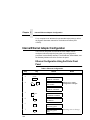
Internal Ethernet Adapter Configuration ............................144
Ethernet Configuration Using the Printer Front Panel.144
Configuring the Internal Ethernet Adapter for TCP/IP .......146
Host Software..............................................................146
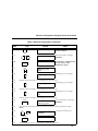
Compiling Host Software.............................................147
7
Table of Contents
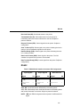
Computer-aided Configuration with ezsetup
or npconfig ..................................................................151
Configuration Through the Network with ARP ............152
Configuration Through the Network with RARP..........154
Configuration Through the Network with BOOTP .......155
Restoring Factory Defaults..........................................155
Host Configuration ......................................................156
Direct Printing Without Spooler ...................................156
Printing Via the Spooler ..............................................158
Custom Interface Scripts.............................................159
BSD UNIX ...................................................................160
System V UNIX ...........................................................164
npd Pseudo-device Interface ......................................166
Other TCP/IP Methods................................................171
Configuring The Internal Ethernet Adapter For Novell ......172
Host Software .............................................................172
Internal Ethernet Adapter ............................................173
Host Configuration ......................................................174
PSERVER Setup (Pre-NetWare 4) .............................175
RPRINTER Setup (Pre-NetWare 4) ............................177
NetWare 4 Options .....................................................180
Configuring the Internal Ethernet Adapter for Windows ....183
Print Methods Overview ..............................................183
TCP/IP Setup ..............................................................184
Configuring TCP/IP .....................................................186
Host Configuration ......................................................189
6 Troubleshooting .................................... 195
Cleaning Requirements .....................................................195
Exterior Cleaning ........................................................195
Interior Cleaning..........................................................196
Diagnosing Problems ........................................................198
Printing a Hex Dump ...................................................198
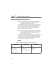
Fault Messages...........................................................200
8
Table of Contents
A Printer Specifications ........................... 207
Ribbon Specifications ........................................................207
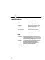
Paper Specifications ..........................................................208
Printer Dimensions ............................................................209
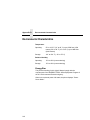
Environmental Characteristics ...........................................210
Electrical Characteristics ...................................................211
Interfaces...........................................................................212
Printing Rates ....................................................................212
B Downloading Firmware......................... 213
Loading Flash Memory ......................................................213
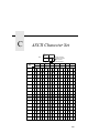
C ASCII Character Set............................. 219
D Communication and
Trademark Information .............................. 221
Communication Notices.....................................................221
Trademark Acknowledgments ...........................................223
9
Table of Contents
10
1
Introduction
Printer Overview
This chapter provides a general overview of your printer and the
conventions used within this manual.
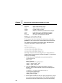
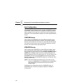
The Printer Family
The Compaq series of line matrix printers consist of 500, 1000, and
1500 lines per minute (lpm) models packaged in various configurations.
All of the models offer software versatility and the latest refinements in
line matrix printing technology. The print mechanisms are housed in
sound-insulated cabinets which make the printer family among the
quietest printers in the world.
Most line matrix printers have specialized architectures, which enable
the printer to emulate, or behave like, another printer. These
specialized architectures are restricted. Your printer, however, has a
flexible architecture that allows new features and emulations to be
added as they become available.
PCL®-II is the standard emulation. LinePrinter Plus® is also included
with each printer. LinePrinter Plus includes the Epson® FX-1050,
Printronix® P-Series, and IBM Proprinter® III XL emulations. The
IGP®/PGL® and IGP/VGL graphics enhancement emulations are
available as optional upgrades. No matter what emulation is installed,
your printer is easy to use. The message display and lights on the
control panel communicate with you directly and clearly. You can select
every function on your printer at the control panel, or you can send
commands from the host computer.
11
Chapter 1
Printer Overview
The printer combines the use of Flash, RAM, and nonvolatile RAM for
program execution. The Flash is used for all program, font, and
emulation storage. New fonts, emulations, or program updates can be
downloaded to Flash memory via the parallel or serial interface. The
RAM is used for buffers, print image storage, and execution variables.
The non-volatile RAM stores configuration, statistics, and internal
parameters.
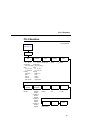
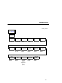
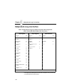
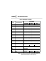
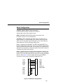
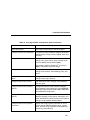
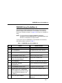
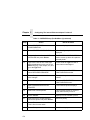
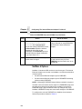
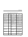
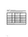
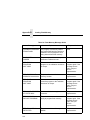
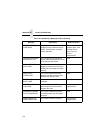
Refer to the following table for a complete listing of model numbers and
options.
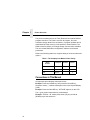
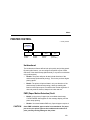
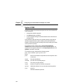
Table 1. The Compaq Line Matrix Printer Family
Model
Number
Print Speed
5525B
500 lpm
5531
1000 lpm
5532
1500 lpm
Pedestal
Cabinet
á
á
á
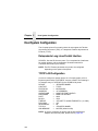
Conventions in This Manual
All uppercase print indicates control panel keys.
Example: Press the CLEAR key, then press the ON LINE key.
Quotation marks (“ ”) indicate messages on the Liquid Crystal Display
(LCD).
Example: Press the ON LINE key. “OFFLINE” appears on the LCD.
The + (plus) symbol represents key combinations.
Example: “Press = + >” means press the = (UP) key and the >
(DOWN) key at the same time.
12
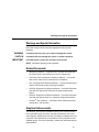
Warnings and Special Information
Warnings and Special Information
Read and comply with all information highlighted under special
headings:
WARNING
Conditions that can harm you as well as damage the printer.
CAUTION
Conditions that can damage the printer or related equipment.
IMPORTANT
Information that is vital to the operation of the printer.
NOTE: Information affecting printer operation.
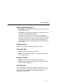
Related Documents
•
Maintenance Manual — Explains how to maintain and repair the
line matrix printer at the field service level of maintenance.
•
LinePrinter Plus Programmer's Reference Manual — Covers the
host control codes for the LinePrinter Plus emulations.
•
PCL-II Programmer's Reference Manual — Covers the host control
codes for the Printer Control Language emulation.
•
IGP/PGL Programmer's Reference Manual — Provides information
used with the optional IGP Printronix emulation enhancement
feature.
•
IGP/VGL Programmer's Reference Manual — Provides information
used with the optional Code VTM emulation enhancement feature.
•
PrintNetTM User’s Manual — Information about network protocols,
configuration, and operation.
Graphics Enhancements
The IGP/PGL and IGP/VGL emulations allow you to create and store
forms, generate logos, bar codes, expanded characters, and create
other graphics. Alphanumeric and bar code data are added as the form
is printed. These emulations are available as factory-installed or fieldinstalled options. For more information, contact your authorized service
representative.
13
Chapter 1
Printer Overview
Taking Care of Your Printer
Your printer will produce high print quality jobs if it is well taken care of.
Periodic cleaning, handling the printer properly, and using the correct
printer supplies such as paper and ribbons ensures optimum
performance. Chapter 6 explains how to clean the printer, and printer
supplies are listed in Appendix A.
Whenever it is necessary to service the printer, remember these
important maintenance concepts:
•
Use only the ribbons specified in Appendix A. Use of incorrect
ribbons can lead to ink migration problems, degraded print quality,
and expensive damage to the printer.
•
Incorrect closure of the forms thickness lever can lead to smearing,
degraded print quality, paper jams, and damage to the platen and
shuttle assembly. Never close the forms thickness lever too tightly.
Protocols and Emulations
A protocol is a set of rules governing the exchange of information
between the printer and its host computer. These rules consist of codes
that manipulate and print data and allow for machine-to-machine
communication. A printer and its host computer must use the same
protocol. As used in this manual, protocol and emulation mean the
same thing.
Most impact printers use single ASCII character codes to print text,
numbers, and punctuation marks. Some characters, both singly and in
groups of two or more, are defined as control codes. Control codes
instruct the printer to perform specific functions, such as underlining
text, printing subscripts, setting page margins, etc. The main difference
between most printer protocols is in the characters used to create
control codes and the ways in which these characters are formatted.
When the printer executes the character and control codes of a
particular printer protocol, it is “emulating” that printer. If the printer uses
the Proprinter XL protocol, for example, it is emulating a Proprinter XL
printer. If the printer is using the Epson FX printer protocol, for example,
we can also say it is in Epson FX emulation mode.
14
2
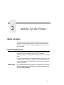
Setting Up the Printer
Before You Begin
Read this chapter carefully before installing and operating the printer.
The printer is easy to install. However, for your safety, and to protect
valuable equipment, perform all the procedures in this chapter in the
order presented.
Power Requirements
The printer must be connected to a power outlet that supplies 88 to 135
Volts AC or 178 to 270 Volts AC at 47 to 63 Hz. The printer
automatically senses and adjusts itself to conform to the correct voltage
range.
Primary circuit protection is provided by the power switch, which is also
a circuit breaker. Consult an electrician if printer operation affects local
electrical lines. See “Printer Specifications” on page 207 for additional
power specifications.
IMPORTANT
It is recommended that printer power be supplied from a separate
AC circuit protected at 10 amperes for 120 volts or 5 amperes for
230 volts at 50 or 60 Hertz.
15
Chapter 2
Select a Site
Select a Site
Select a printer site that meets all of the following requirements:
•
•
Permits complete opening of the printer cover and doors.
•
Has a standard power outlet that supplies 88-135 Volts AC or 178270 Volts AC power, at 47 to 63 Hz.
•
•
Is relatively dust-free.
•
For cabinet models, allows at least three feet of clearance behind
the printer. (This permits air to circulate freely around the printer
and provides access to the paper stacking area.)
Has a temperature range of 10° C to 40° C (50° F to 104° F), and a
relative humidity from 15% to 90% non-condensing.
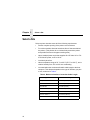
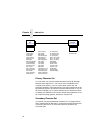
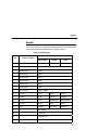
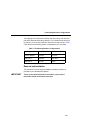
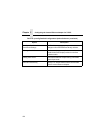
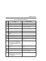
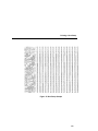
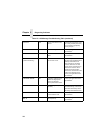
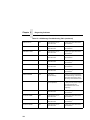
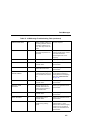
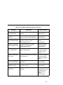
Is located within the maximum allowable cable length to the host
computer. This distance depends on the type of interface you plan
to use, as shown in Table 2.
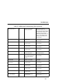
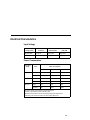
Table 2. Maximum Interface Connection Cable Length
16
Interface Type
Maximum Cable Length
Dataproducts Parallel
12 meters (40 feet)
IEEE 1284 Parallel
10 meters (32 feet)
Serial RS-232
15 meters (50 feet)
Serial RS-422
1220 meters (4000 feet)
Dataproducts Long Line
150 meters (492 feet)
Ethernet 10Base-T
100 meters (328 feet)
Ethernet 10Base2
185 meters (607 feet)
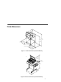
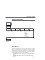
Printer Dimensions
57.5 in.
(146.1 cm)
41.0 in.
(104 cm)
27.0 in.
(68.6 cm)
29.0 in.
83.0 in.
(73.7 cm)
(210.8cm)
27.0 in.
27.0 in.
(68.6 cm)
(68.6 cm)
Figure 1. Printer Dimensions (Cabinet Model)
m)
25 in.
(63.5 cm.)
10.5 in.
(26.67 cm.)
48.0 in.
(122 cm.)
24.6 in.
(62.48 cm.)
30 in.
(76.2 cm.)
Figure 2. Printer Dimensions (Pedestal Model)
17
Chapter 2
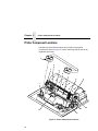
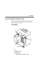
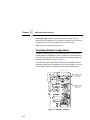
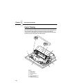
Printer Component Locations
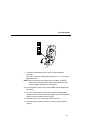
Printer Component Locations
Familiarize yourself with the names and locations of the printer
components, shown in Figure 3, before continuing with the rest of the
installation procedure.
2
4
3
5
6
7
8
9
1
10
11
13
12
Figure 3. Printer Component Locations
18
Legend:
1)
2)
3)
4)
5)
6)
7)
8)
9)
10)
11)
12)
13)
Hub Latch
Ribbon Spool
Horizontal Adjustment Knob
Tractor Lock
Paper Scale
Splined Shaft
Paper Support
Tractor
Hammer Bank Cover and Ribbon Mask
Vertical Position Knob
Forms Thickness Lever
Ribbon Guide
Ribbon Loading Path Diagram
Remove Packing Materials
CAUTION
To avoid shipping damage, reinstall the shipping restraints
whenever you move or ship the printer.
Save the cardboard packing, foam blocks, and bubble wrap along with
the other packing materials in case you need to move the printer. If it is
necessary to move the printer, reinstall the shipping restraints,
reversing the steps in this section.
19
Chapter 2
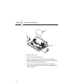
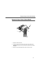
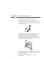
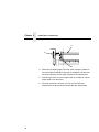
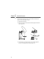
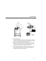
Remove Packing Materials
3
1
2
1. Raise the printer cover.
2. Remove the cardboard packing (1).
3. Open the tractor doors. Push the tractor locks down. Slide the
tractors outward as far as they will go. The forms thickness lever (2)
should be in the fully open (raised) position.
4. Remove the envelope (3) containing the sample configuration
printout. Store the envelope in the pouch attached to the left interior
side of the cabinet.
20
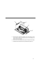
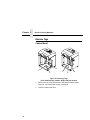
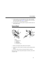
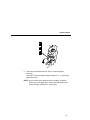
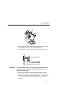
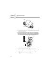
6
5
4
7
5. Slide the paper supports (4) outward as far as they will go. Lift the
hammer bank protective foam (5) and remove it from between the
ribbon mask and the platen.
6. Remove the foam strips (6) and the tape securing the foam strips.
7. Rotate the forms thickness lever (7) downward to position “A”.
21
Chapter 2
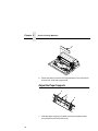
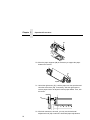
Remove Packing Materials
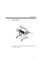
8
8. Rotate the platen protective foam (8) toward the front of the printer
and out from under the support shaft.
Adjust the Paper Supports
2
1
2
1. Slide the paper supports (1) inward until they are approximately
four inches from the tractor doors (2).
22
Release the Paper Chains (Cabinet Model)
Release the Paper Chains (Cabinet Model)
1
2
1
3
1. Open the cabinet rear door.
2. Cut the tie wraps (1) and release the paper chains (2) from the
bags (3) at the top rear of the printer frame. Remove the tie wraps
and bags.
3. Make sure each chain hangs freely, with no kinks or knots.
23
Chapter 2
Remove Packing Materials
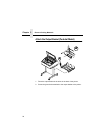
Remove Tags
Cabinet Model
3
1
2
1
2
3
Figure 4. Removing Tags
(Left: 1000/1500 lpm models; Right: 500 lpm models)
1. Remove the tie wrap (1) attached to the passive stacker paper
fence (3). It is marked with a large, red tag (2).
2. Close the cabinet rear door.
24
Remove Tags
Pedestal Model
3
1
2
Remove the tie wrap (1) attached to the output basket (3). It is marked
with a large, red tag (2).
25
Chapter 2
Remove Packing Materials
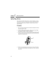
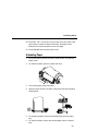
Attach the Output Basket (Pedestal Model)
$
$
1. Place the output basket in the holes in the back of the printer.
2. Screw the ground wire attached to the output basket to the printer.
26
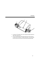
Cabinet Model
Connect the Interface and Power Cords
Before you connect the interface and power cables, verify the voltage
source at the printer site conforms to the requirements specified in
“Power Requirements” on page 15.
Cabinet Model
1
2
5
4
3
Legend:
1)
2)
3)
4)
5)
Host Interface Connectors
I/O Cover
Cable-Routing Notches
AC Power Cable
AC Power Connection
Figure 5. Interface and Power Locations
27
Chapter 2
Connect the Interface and Power Cords
1. Make sure the printer power switch is set to O (Off).
2. Open the cabinet rear door, and remove the cover from the
selected I/O connector. (See “Interface Connections” on page 30.)
3. Locate the cable routing notch in the lower left corner of the back of
the cabinet (see Figure 5).
4. Hold the I/O cable below its connector and gently push the cable
through the opening in the grommet seated in the notch.
5. Pull the cable up through the notch until it reaches the I/O plate.
Attach the cable connector to the printer interface connector
previously selected in step 2 of this section. Secure the cable to the
printer using the upper and lower standoffs.
6. Open the cabinet front door and cut the strap that secures the box,
which contains the power cord, printer ribbon, control panel overlay
labels, and documentation.
7. Open the box and remove the power cord, overlays, and
documentation.
28
Pedestal Model
8. Guide the power cord up through the hole in the lower right back
corner of the cabinet (see Figure 5). Thread the power cord inside
the bracket where the gas spring is attached.
9. Plug the power cord into the printer AC power connector, then into
the AC power outlet.
Pedestal Model
4
1
2
5
3
Legend:
1)
2)
3)
4)
5)
Parallel Connector
Auxiliary I/O
Serial Connector
Power Switch
AC Power Connector
1. Make sure the printer power switch is set to O (OFF).
2. Remove the cover from the I/O connector you have selected. (See
below.)
3. Attach the cable connector to the printer interface connector.
Plug the power cord into the printer AC power connector, then into the
AC power outlet.
29
Chapter 2
Connect the Interface and Power Cords
Interface Connections
1
5
2
3
2
3
1
4
4
Legend:
1)
2)
3)
4)
5)
Parallel (not present on Network-based models)
Auxiliary I/O
Diagnostic
Serial RS-232/RS-422
Dataproducts Standard Adapter
Figure 6. Standard Interfaces
(Left: Pedestal Model; Right: Cabinet Model)
1
2
3
Legend:
1)
2)
3)
Network 10Base2
Network 10Base-T
Dataproducts Long Line
Figure 7. Optional Interfaces for the Auxiliary I/O
1. Remove the cover from the I/O connector you have selected.
2. Attach the I/O cable connector to the printer interface connector.
30
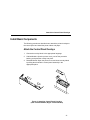
Attach the Control Panel Overlays
Install Basic Components
The following procedures describe how to attach the printed overlays to
the control panel and install the printer ribbon and paper.
Attach the Control Panel Overlays
1. Choose the overlay labels in the appropriate language.
2. Cabinet Models: Open the printer cover, peel off the protective
backing, and press the overlay into place.
3. Pedestal Models: Open the printer cover and insert overlay labels
by sliding them behind the control panel assembly in the
appropriate place.
Figure 8. Attaching Control Panel Overlays
(Left: Pedestal Models; Right: Cabinet Models)
31
Chapter 2
Install Basic Components
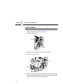
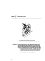
Load the Ribbon
1. Refer to the ribbon path diagram molded onto the shuttle cover (see
“Printer Component Locations” on page 18).
2. Open the printer cover.
2
1
3. Raise the forms thickness lever (1) as far as it will go.
4. Open the tractor doors (2).
3
5. Squeeze the right hub latch (3) and place the full spool on the right
hub. Be sure the ribbon feeds off the outside of the spool. Press the
spool down until the hub latch snaps into place.
32
Load the Ribbon
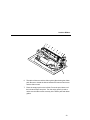
4
6. Thread the ribbon around the ribbon guide (4) and along the ribbon
path. Be sure to thread the ribbon between the hammer bank cover
and the ribbon mask.
7. Place the empty spool on the left hub. Press the spool down until
the hub latch snaps into place. Turn the empty spool by hand to
make sure the ribbon tracks correctly in the ribbon path and ribbon
guides.
33
Chapter 2
Install Basic Components
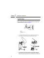
Load the Paper
When you start this procedure, verify that the printer cover is open, the
forms thickness lever is raised, and the tractor doors are open. (See
“Printer Component Locations” on page 18).
1
2
Legend:
1)
2)
Edge Of Paper
Box
1. For cabinet models, align the paper supply with the label on the
floor. Make sure that the paper pulls freely from the box.
3
3
2. Feed the paper up through the paper slot (3). Hold the paper in
place with one hand (to prevent it from slipping down through the
paper slot) while pulling it through from above with your other hand.
34
Load the Paper
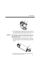
5
4
6
3. Pull the paper (4) above and behind the ribbon mask, which is a
silver metal strip with a clear plastic edge protector. Load the paper
on the left tractor sprockets and close the tractor door (5).
CAUTION
To avoid damage to the printer caused by printing on the platen,
always position the left tractor unit directly to the left of the “1”
mark on the paper scale.
4. If adjustment is necessary, unlock (6) the left tractor. Slide the
tractor until it is directly to the left of the number “1” on the paper
scale (10) and lock it. You can also use the paper scale to count
columns.
7
5. Unlock the right tractor (7). Load the paper onto the right tractor
sprockets and close the tractor door.
35
Chapter 2
Install Basic Components
8
9
10
6. Make sure the leading edge of the first sheet of paper is parallel to
the tractor splined shaft (8). If the paper is misaligned, reload it onto
the tractor sprockets until its edge is parallel to the splined shaft.
7. Slide the right tractor to remove paper slack or to adjust for various
paper widths. Lock the tractor.
8. After both tractors are secured, you may use the horizontal
adjustment knob (9) to make fine horizontal paper adjustments.
36
Load the Paper
A
B
C
9. Lower the forms thickness lever. Set it to match the paper
thickness.
(The A-B-C scale corresponds approximately to 1-, 3-, and 6-part
paper thickness.)
NOTE: Do not set the forms thickness lever too tightly; excessive
friction can cause paper jams, ribbon jams with potential for
ribbon damage, smeared ink, or wavy print.
37
Chapter 2
Set the Top-of-Form
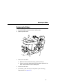
Set the Top-of-Form
When paper is loaded into the printer, it must be told where you want
the top of your form to be. This procedure must be performed the first
time paper is introduced into the printer, as well as every time new
paper is loaded.
Procedure
1. Be sure the forms thickness lever is lowered. If the printer is off, set
the power switch to I (On).
2. Press ON LINE to place the printer in offline mode. The LCD will
then display “OFFLINE / CONFIG. CONTROL.”
3. Press FF several times to ensure the paper feeds properly beyond
the tractors and over the lower paper path. Ensure the paper folds
properly in the stacking area.
2
1
4. Raise the forms thickness lever (1) as far as it will go. This allows
you to turn the vertical position knob (2) freely in order to align the
top-of-form.
38
Procedure
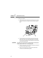
3
4
5
5. Locate the TOF indicator (3). It is the small tab located on both the
right and left tractor door.
6. Turn the vertical position knob (5) to align the top of the first print
line with the TOF indicator. For best print quality, it is recommended
the top-of-form be set at least 1/2 inch below the perforation (4).
39
Chapter 2
Set the Top-of-Form
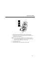
A
B
C
7. Lower the forms thickness lever. Set it to match the paper
thickness. (The A-B-C scale corresponds approximately to 1-, 3-,
and 6-part paper thickness.)
NOTE: Do not set the forms thickness lever too tightly; excessive
friction can cause paper jams, ribbon jams with potential for
ribbon damage, smeared ink, or wavy print.
8. Press SET TOF. The top-of-form position you have set moves
down to the print position.
9. Press CLEAR to remove any fault messages (such as “LOAD
PAPER”) from the message display.
10. Press ON LINE to place the printer in online mode.
40
3
Operating the Printer
Powering On the Printer
When you power on the printer, it executes a self-test. The default
power-up state is online. When the self-test completes and the software
has initialized successfully, the status indicator light turns on, indicating
the printer is online. The default value of the type of emulation you have
installed appears in the display.
If there is a fault during the self-test, the status indicator flashes and a
specific fault message appears on the display (such as “LOAD
PAPER”). The alarm also sounds if it is configured to do so. See
“Troubleshooting” on page 195 for information on fault messages and
solutions.
Operating Modes
Online. In online mode, the printer can receive and print data sent from
the host. Pressing the ON LINE key toggles the printer from offline to
online mode. The status indicator is lit in online mode.
Offline. In offline mode, you may perform operator functions, such as
loading paper and setting top-of-form. You may also move within the
printer configuration menus. Pressing the ON LINE key toggles the
printer from online to offline mode. The status indicator is off in offline
mode.
Fault. In fault mode, a fault condition exists which must be cleared
before printing can continue. The status indicator flashes, the alarm
beeps (if configured to sound), and a descriptive fault message
displays.
41
Chapter 3
The Control Panel
The current operating mode may be selected via control panel keys, or
may result from routine operations such as powering on the printer.
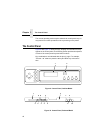
The Control Panel
Figure 9 and Figure 10 show the keys, displays and indicators as they
appear on the control panel. The following section provides descriptions
of each of the control panel keys and their functions.
Key combinations are indicated with the plus (+) sign. For example,
“Press = + >” means to press the = key and the > key at the same
time.
2
1
3
4
5
7
8
9
6
Figure 9. Control Panel, Cabinet Model
2
1
= >
;
<
3
5
4
7
6
9
8
10
Figure 10. Control Panel, Pedestal Model
42
10
Control Panel Keys
Legend:
1)
2)
3)
4)
5)
6)
7)
8)
9)
10)
Message Display
Status Indicator
CLEAR
SHIFT
SET TOF / L.P.I. ADJ.
ENTER / PAGE L. ADJ.
ON LINE
FF
LF
VIEW
Control Panel Keys
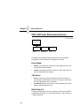
ON LINE
Toggles the printer between online and offline modes. If a fault
condition exists, pressing this key will clear the fault message and
return the printer from fault mode to offline mode.
NOTE: If the fault condition is not corrected before pressing this key,
the fault message will reappear when attempting to place the
printer online.
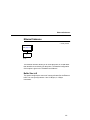
FF (Form Feed)
Causes the paper to advance to the top-of-form on the next page.
In online or offline mode, press and release to advance the paper to
top-of-form on the next page. If there is data in the printer buffers, the
data will print and then the paper will move to the next top-of-form.
In the fault state, FF does not advance the paper to the next top-ofform; instead, it will slew the paper 11 inches.
LF (Line Feed)
Advances the paper one line at a time. Unprinted data in the print buffer
will print before the paper moves.
With the printer offline, press and release to advance the paper one line
at a time. If there is data in the printer buffer, the data will print before
the line feed occurs. Press and hold to repeat forward paper movement.
LF does not operate in the fault or online states.
43
Chapter 3
The Control Panel
VIEW
In offline or online mode, allows you to view and adjust the placement of
data on the page, or to remove peel-off labels.
With the printer online or offline, press and release to move paper
forward for inspection. The last data printed advances to the tractor
area. Press VIEW a second time to move the paper back to its previous
print position.
If the printer is online and printing, press VIEW to stop printing. The
paper advances. Press = or > to move 1/72” vertically for fine vertical
forms alignment. Press VIEW. The paper moves back and printing
resumes.
Pressing ON LINE also moves the paper back to its original print
position and returns the printer to online.
CLEAR
Clears a fault message and returns the printer from fault mode to offline
mode.
After correcting the fault, press and release. The fault message is
cleared, and the printer returns to offline mode.
Other functions:
44
•
Moves to the top of the configuration menu when the printer is in
the configuration menus.
•
Cancels data in the buffer. Place the printer offline. From the host
system, stop the print job. Press CLEAR+ENTER. Reset the top-ofform (page 38).
•
Press SHIFT+CLEAR to reset the PCL-II emulation.
Control Panel Keys
SHIFT
The printer must be offline to perform the following functions:
•
•
Press SHIFT+CLEAR to reset the PCL-II emulation.
•
Press SHIFT+Page L. Adj to access the form length menu in lines
or inches. The page length is selected by lines/page or inches/
page, depending on which option is chosen in the PCL-II submenu.
•
Press SHIFT+= to micro step the paper upward in 1/72 inch
increments.
•
Press SHIFT+> to micro step the paper downward in 1/72 inch
increments.
Press SHIFT+L.P.I. Adj to access the line spacing menu. Press
PREV or NEXT to scroll through the options.
SET TOF
Sets the top-of-form on the printer. This key is active only when the
printer is offline and will not operate if the printer is in a fault condition.
The paper moves down to the print position and aligns to the top-ofform. See page 38 for the complete top-of-form setting procedure.
NOTE: If there is any data in the buffer, the paper will move to the last
print position.
ENTER
When navigating the configuration menus, ENTER selects the currently
displayed option value as the active value. An asterisk (*) appears next
to the active value on the display. ENTER is also used for starting and
stopping printer tests and generating a configuration printout.
NOTE: The ENTER key must be unlocked in order to function. See
UP + DOWN, below.
45
Chapter 3
The Control Panel
UP or DOWN ( = or > )
Moves up and down between levels in the configuration menus and
makes vertical forms adjustment. After pressing VIEW, press = or > to
adjust the paper up or down in 1/72 inch increments for fine vertical
forms alignment. After pressing ON LINE, press = or > to move through
levels in the configuration menus.
UP + DOWN ( = + > )
Locks and unlocks the ENTER key.
PREV or NEXT ( ; or < )
Moves between the options on the current level of configuration menu.
In the configuration menu press ; to scroll backward or press < to scroll
forward through the menu selections on the same level.
PREV + NEXT ( ; + < )
When both keys are pressed simultaneously, the printer performs a soft
reset of the LP+ emulation and the printer buffers are cleared.
46
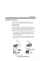
Reloading Paper
Operational Procedures
This section outlines certain basic procedures which need to be
performed when necessary in order to keep your printer operating.
Reloading Paper
Follow this procedure when “LOAD PAPER” displays. (This message
occurs when the last sheet of paper passes through the paper slot.)
This procedure reloads paper without removing the last sheet of the old
paper supply. This action retains the current top of form setting.
1. Raise the printer cover. Raise the forms thickness lever as far as it
will go. (See Figure 3 on page 18 for the location of the lever.)
2. Press CLEAR to turn off the alarm. Do not open the tractor doors or
remove the existing paper.
3. For cabinet models, open the front door. Align the paper supply
with the label on the floor. Ensure the paper pulls freely from the
box.
2
1
Legend:
1)
2)
Paper Slot (Cabinet Model)
Paper Slot (Pedestal Model; 8” below printer base)
Figure 11. Paper Slot Location
47
Chapter 3
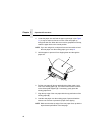
Operational Procedures
4. Locate the paper slot and feed the paper up through it (see Figure
11). It may be easier to feed one corner of the new paper up
through the slot first. When this corner can be grasped from the top,
rotate the paper back to the normal position.
NOTE: If you are using thick, multi-part forms and are unable to load
the new paper over the existing paper, go to step 14.
5. Hold the paper to prevent it from slipping down and through the
paper slot.
3
4
6
5
6. Pull the new paper (3) above and behind the ribbon mask, but in
front of the existing paper (4). The ribbon mask location is shown
on the ribbon path diagram (5). If necessary, gently press the
existing paper back.
7. Align the top edge of the new paper with the top perforation of the
existing paper (6).
8. Load the new paper over the existing paper. Open and load the
tractors one at a time to prevent the paper from slipping.
NOTE: Make sure that the top edge of the new paper lines up with the
top horizontal perforation of the last page.
48
Reloading Paper
A
B
C
9. Lower the forms thickness lever. Set it to match the paper
thickness.
(The A-B-C scale corresponds approximately to 1-, 3-, and 6-part
paper thickness.)
NOTE: Do not set the forms thickness lever too tightly; excessive
friction can cause paper jams, ribbon jams with potential for
ribbon damage, smeared ink, or wavy print.
10. Press CLEAR to remove the “LOAD PAPER” fault message from
the display.
11. Press FF several times to make sure the paper feeds properly
beyond the tractors and over the lower paper guide. Feed sufficient
paper to ensure the paper stacks correctly.
12. Close the printer cover. Close the cabinet front door.
13. Press ON LINE to place the printer in online mode and resume
printing.
49
Chapter 3
Operational Procedures
Perform steps 14 through 30 only if you are unable to load the new
paper over the existing paper in step 4.
14. Open both tractor doors.
15. Remove the paper from the tractors. Allow the paper to fall into the
paper supply area.
7
7
16. Feed the paper up through the paper slot (7). Hold the paper to
prevent it from slipping down through the paper slot.
50
Reloading Paper
9
8
17. Pull the paper (8) above and behind the ribbon mask. (The ribbon
mask location is shown on the ribbon path diagram.)
18. Load the paper on the left tractor and close the tractor door (9).
CAUTION
To avoid damage to the printer caused by printing on the platen,
always position the left tractor unit directly to the left of the “1”
mark on the paper scale.
19. Normally, you should not need to adjust the position of the left
tractor. If adjustment is necessary, unlock the left tractor. Slide the
tractor until it is directly to the left of the number “1” on the paper
scale and lock it. (You can also use the paper scale to count
columns.)
51
Chapter 3
Operational Procedures
10
20. Move the paper supports (10) as necessary to support the paper
between the tractors.
11
12
21. Unlock the right tractor (11). Load the paper onto the sprockets and
close the tractor door (12). If necessary, slide the right tractor to
remove paper slack or to adjust for various paper widths. Then, lock
the tractor.
13
22. After both tractors are secured, you may use the horizontal
adjustment knob (13) to make fine horizontal paper adjustments.
52
Reloading Paper
14
14
23. On pedestal models:
Using the vertical position knob to move the paper up, guide the
paper over the lower paper guide (14) and through the slot in the
top cover. Close the platen and the printer cover.
24. Press FF several times to make sure the paper feeds properly
beyond the tractors and over the lower paper guide (14). Feed
sufficient paper to ensure the paper stacks correctly.
25. On cabinet models: Open the cabinet rear door. Make sure the
paper is aligned with the label in the output area (inside the
cabinet). Close the front and rear doors.
53
Chapter 3
Operational Procedures
15
17
16
26. Locate the TOF indicator (15). It is the small tab located on both the
right and left tractor door.
27. Turn the vertical position knob (16) to align the top of the first print
line with the TOF indicator. For best print quality, it is recommended
the top-of-form be set at least 1/2 inch below the perforation (17).
A
B
C
28. Lower the forms thickness lever. Set it to match the paper
thickness. (The A-B-C scale corresponds approximately to 1-, 3-,
and 6-part paper thickness. Adjust until you have the desired print
quality.)
29. Press CLEAR to clear any fault messages (such as “LOAD
PAPER”) from the Liquid Crystal Display.
54
Unloading Paper
30. Press SET TOF. The top-of-form you have set moves down to the
print position. If there are data in the buffer, the paper moves
forward to the last print position on the next page.
31. Press ONLINE and close the printer cover.
Unloading Paper
1. Press ON LINE to place the printer in offline mode, and open the
printer cover.
2. For cabinet models, open the cabinet rear door.
3. Tear off the paper at the perforation.
4. Allow the paper to fall to the back of the printer and into the paper
stacking area.
5. For pedestal models, remove the stacked paper from the paper
tray.
6. For cabinet models, remove the stacked paper from the cabinet
floor.
55
Chapter 3
Operational Procedures
2
1
7. To completely remove the paper from the printer:
a. Raise the forms thickness lever (1) as far as it will go, and open
both tractor doors (2).
CAUTION
Be careful when pulling any paper backward through the paper
path, especially when using a label stock. If you are not careful,
labels can detach and adhere to the printer within the paper path,
where only an authorized service representative can remove them.
b. Remove the paper from the tractors. For cabinet models, open
the cabinet front door. Gently pull the paper down through the
paper slot. Allow the paper to fall into the paper supply area.
c.
56
Remove the paper from the paper supply area.
Replacing the Ribbon
Replacing the Ribbon
1. Press ON LINE to place the printer in offline mode.
2. Open the printer cover.
2
1
3. Remove the old ribbon:
a. Raise the forms thickness lever (1) as far as it will go.
b. Press in on the hub latches (2) and lift the ribbon spools off the
hubs. Lift the ribbon out of the ribbon path.
4. Discard the old ribbon.
5. If necessary, clean the interior of the printer. (See “Cleaning
Requirements” on page 195.)
57
Chapter 3
Operational Procedures
6. Install the new ribbon:
a. With the ribbon to the outside, place the full spool on the right
hub (3). Press down on the spool until the hub latch snaps in
place.
3
4
b. Thread the ribbon around the ribbon guide (4) and along the
ribbon path. (Refer to the ribbon path diagram on the shuttle
cover.) Be sure to thread the ribbon between the hammer bank
cover and the ribbon mask.
CAUTION
The ribbon must not be twisted. A twisted ribbon can lower print
quality, shorten ribbon life, or cause paper jams.
c.
Place the empty spool on the left hub. Press down on the spool
until the hub latch snaps into place.
d. Hand turn the empty spool to make sure the ribbon tracks
correctly in the path and ribbon guides.
58
Replacing the Ribbon
A
B
C
7. Lower the forms thickness lever. Set it to match the paper
thickness. (The A-B-C scale corresponds approximately to 1-, 3-,
and 6-part paper thickness.)
NOTE: Do not set the forms thickness lever too tightly; excessive
friction can cause paper jams, ribbon jams with potential for
ribbon damage, smeared ink, or wavy print.
8. Close the printer cover.
9. Press ON LINE to return the printer to online mode.
59
Chapter 3
Operational Procedures
Canceling a Print Job
The procedure to cancel a print job depends on the printer emulation
and your application software. Contact your System Administrator for
additional information.
1. If the printer is online, press ON LINE to place the printer in offline
mode.
2. From the host system, stop the print job.
NOTE: If the print job is not stopped from the host system before
pressing CLEAR + ENTER, the print job continues with data
missing when the printer returns to online mode. Exercise
caution to prevent unwanted data loss occurrences, as this
function deletes unprinted data in the printer. This function is
active only in offline mode; the purpose of this function is to
eliminate the necessity of printing unwanted data when print
jobs are canceled.
3. Press CLEAR + ENTER.
4. Set the top-of-form (see “Set the Top-of-Form” on page 38).
60
4
The Configuration
Menus
Configuration Overview
In order to print data, the printer must respond correctly to signals and
commands received from the host computer. Configuration is the
process of matching the printer’s operating characteristics to those of
the host computer and to specific tasks, such as printing labels, or
printing on different sizes of paper. The characteristics which define the
printer’s response to signals and commands received from the host
computer are called configuration parameters.
You can configure the printer using the configuration menus and the
control panel, or by sending control codes in the data stream from a
host computer attached to the printer. This chapter provides an
introduction to configuring the printer, as well as all the configuration
menus available (depending on which emulation you have installed in
the printer).
IMPORTANT
Configuration directly affects printer operation. Do not change the
configuration of your printer until you are thoroughly familiar with
the procedures in this chapter.
61
Chapter 4
Configuration Overview
Changing and Saving Parameter Settings
You may change a printer parameter setting, such as line spacing or
forms length, either by pressing keys on the control panel to configure
the printer’s resident set of configuration menus, or by sending
emulation control codes from a host attached to the printer (the host
data stream). An example procedure for using the control panel to
change parameter settings begins on page 64.
When control codes are sent from a host attached to the printer, they
override control panel settings. For example, if you set the line spacing
to 6 lpi with the control panel, and application software later changes
this to 8 lpi with a control code, the control code overrides the control
panel setting.
The parameter settings that you have changed using the menus and
control codes can be permanently stored in the printer’s memory if you
save them to printer memory using the “Save Config.” menu option. If
you do not save your changes, they will be lost when the printer is
powered off.
There are no host control codes that allow you to save a parameter as a
custom configuration.
Default and Custom Configurations
A configuration consists of a group of parameter settings, such as line
spacing, forms length, etc. Your printer provides a fixed default
configuration and also allows you to define several custom
configurations for use with particular print jobs.
The factory default configuration can be loaded, but it cannot be
altered.
Eight configurations can be modified for unique print job requirements.
The “Save Config.” option allows you to save eight groups of parameter
settings in memory as custom configurations numbered from 1 through
8. An explanation on how to save a set of parameter values as a
custom configuration using the “Save Config.” menu option begins on
page 66.
62
Navigating the Menus
Navigating the Menus
To manipulate configurations it is important to understand how to
navigate through the menus. Review the following instructions before
you begin making changes to the printer.
You must be offline to move within the menus.
ON LINE
OR
OR
ENTER
+
Press to toggle between online and offline
modes.
Press to move up or down through the menu
levels.
Press to scroll through the available choices
on a chosen level.
Press to confirm selection.
Press to lock and unlock the ENTER key. The
ENTER key is locked by default, to prevent
you from accidentally changing the printer
configuration.
When the printer is online, the LCD displays ONLINE and the type of
emulation on the second line.
To experiment with navigating the menus, follow the example on the
next page as a tutorial.
63
Chapter 4
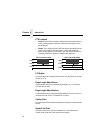
Configuration Overview
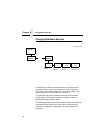
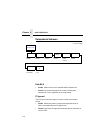
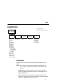
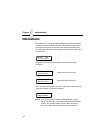
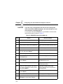
Changing Parameters Example
* = Factory Default
OFFLINE
CONFIG.
CONTROL
...
PRINTER
CONTROL
Unidirectional
Disable*
Enable
PMD Fault
Enable*
Disable
Slow Paper
Slew
Disable*
Enable
Power Saver
Time
15 min.*
(15-60 min.)
A configuration consists of several parameters. The default factory
configuration has a starting set of parameters. In the configuration
menu above, and in all the configuration menus in this chapter, the
factory default values are indicated by an asterisk (*).
Your print jobs may require parameter values which vary from the
default settings. This section provides an example procedure for
changing individual parameter values.
The following procedure shows how to change and save the settings for
the Unidirectional and Slow Paper Slew options. Use these basic
guidelines to navigate the configuration menus and change other
parameters.
64
Changing Parameters Example
Step
1.
2.
Press
LCD
Notes
Make sure the printer is on. Raise the printer cover.
ON LINE
3.
+
OFFLINE
CONFIG. CONTROL
ENTER SWITCH
UNLOCKED
Allows you to make
configuration changes.
OFFLINE
CONFIG. CONTROL
4.
UNTIL
OFFLINE
PRINTER CONTROL
5.
PRINTER CONTROL
Unidirectional
6.
Unidirectional
Disable*
7.
OR
8.
ENTER
9.
Unidirectional
Enable
Cycle through the
choices.
Unidirectional
Enable*
The * indicates this choice
is active.
PRINTER CONTROL
Unidirectional
10.
UNTIL
11.
PRINTER CONTROL
Slow Paper Slew
Slow Paper Slew
Disable*
12.
OR
Slow Paper Slew
Enable
Press until the desired
parameter displays.
65
Chapter 4
Step
13.
Configuration Overview
Press
ENTER
14.
+
15.
ON LINE
LCD
Notes
Slow Paper Slew
Enable*
The * indicates this choice
is active.
ENTER SWITCH
LOCKED
Locks the ENTER key.
ONLINE
LinePrinter+
Places the printer in
online mode.
16. Close the printer cover. The printer is ready for operation.
The parameters you have changed remain active as long as the printer
is on. When you turn off the printer, the parameters are erased from
memory unless you save them in a configuration. If you do not save the
configuration, the printer reverts to the default values next time the
printer is powered on.
The next section, “Saving Your New Configuration”, will explain how to
save configurations.
Saving Your New Configuration
Once you have changed all of the necessary parameters, it is
recommended you save them as a configuration that can be stored and
loaded for future use. If you do not save your configuration before you
power off the printer, all of your parameter changes are erased. The
Save Config. option allows you to save up to eight configurations to
meet different print job requirements. (Configurations 1 through 8 are
empty until you save values to them using the Save Config. option.)
66
Saving Your New Configuration
Once you have saved a custom configuration using this option, it is not
lost if you power off the printer. You can load a configuration for a
specific print job (see “Load Config.” on page 71). You can also modify
and resave it. You may want to print your configurations (see “Print
Config.” on page 72) and store them in a safe place, such as inside the
printer cabinet.
If the Protect Configs. parameter is enabled, and you try to resave an
existing configuration, the new configuration will not be saved until the
existing configuration has been deleted (see page 72).
NOTE: Once you change active emulations, any changes to the
previously selected emulation will be gone unless they have
been saved.
Step
1.
2.
Press
LCD
Notes
Make sure the printer is on. Raise the printer cover.
ON LINE
3.
+
OFFLINE
CONFIG. CONTROL
ENTER SWITCH
UNLOCKED
Allows you to make
configuration changes.
OFFLINE
CONFIG. CONTROL
4.
CONFIG. CONTROL
Load Config.
5.
UNTIL
6.
CONFIG. CONTROL
Save Config.
Save Config.
1*
7.
OR
Save Config.
2
Cycle through the
choices.
67
Chapter 4
Step
8.
NOTE:
Configuration Overview
Press
ENTER
The * indicates this choice
is active.
CONFIG. CONTROL
Save Config.
10.
UNTIL
11.
CONFIG. CONTROL
Print Config.
Print Config.
Current
12.
OR
ENTER
14.
+
15.
Save Config.
2*
Notes
It is recommended you print the configuration. To print the configuration go to Step 9. To
skip this procedure and resume printer operation, go to Step 14.
9.
13.
LCD
ON LINE
Print Config.
2
Press until the desired
parameter displays.
OFFLINE
CONFIG. CONTROL
The selected
configuration is printed.
ENTER SWITCH
LOCKED
Locks the ENTER key.
ONLINE
LinePrinter+
16. Close the printer cover. If you printed out the configuration, store it in a safe place. The printer is
ready for operation.
68
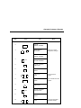
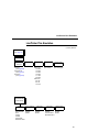
Main Menu
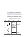
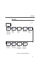
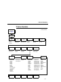
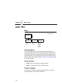
Main Menu
1
If installed
OFFLINE
CONFIG.
CONTROL
page 71
Load Config.
Save Config.
Print Config.
Delete Config.
Power-up Config.
Protect Configs.
ETHERNET
PARAMS1
page 122
IP Address
Gateway Address
Subnet Mask
MAC Address
ACTIVE
EMULATION
page 73
PCL-II
LP PLUS
IGP/PGL1
IGP/VGL1
PRINTER
CONTROL
page 123
Unidirectional
PMD Fault
Slow Paper Slew
Power Saver Time
EMULATION
MAINT/MISC
page 74
page 112
PCL-II
LP PLUS
IGP/PGL1
IGP/VGL1
Hex Dump Mode
Power-up State
Display Language
page 125
RIBBON
MINDER
page 128
Printer Tests
Test Width
Paper Out Dots
System Memory
Print Statistics
New Ribbon
Ribbon Action
Ribbon Size
Ribbon Adjust
Fault Action
DIAGNOSTICS
HOST
INTERFACE
page 113
Dataproducts
Serial
Ethernet1
IEEE 1284
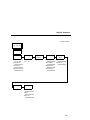
Figure 12. Configuration Main Menu
69
Chapter 4
Configuration Overview
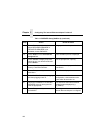
Brief descriptions follow for the first-level configuration menu options:
70
•
CONFIG. CONTROL — These options allow you to save, print,
load, delete, name, and protect entire sets of configuration
parameters, as well as select the default power-up configuration.
•
ACTIVE EMULATION — This menu allows you to select the active
emulation: PCL-II or LinePrinter+. The optional IGP/PGL or
IGP/VGL emulations can be selected if they are installed.
•
EMULATION — This menu allows you to configure the options
which are available for the current operating (active) emulation. For
example, if LinePrinter+ is the active emulation, then the
LinePrinter+ emulation options can be configured using this menu.
•
MAINT / MISC — These options provide miscellaneous functions,
such as printing a hex dump, selecting a display language, and
choosing whether the printer will power up in offline or online mode.
•
HOST INTERFACE — These options allow you to select either the
Serial RS-232, Serial RS-422, Dataproducts® Long Line,
Ethernet™, or IEEE1284 parallel interface for the printer (which
must match the interface cabling you installed while setting up your
printer, described in Chapter 2). This menu also allows you to
configure several parameters for each interface.
•
ETHERNET PARAMS — This option allows you to view and
change the IP Address, Gateway Address, and Subnet Mask. The
MAC Address may also be viewed.
•
PRINTER CONTROL — These options allow you to select several
operating parameters for the printer, such as the speed at which
paper will advance when slewing.
•
DIAGNOSTICS — These options include the diagnostic tests,
system memory, and statistics of the printer.
•
RIBBONMINDER — The options in this submenu allow you to
enable the RibbonMinder™ feature and set its parameters.
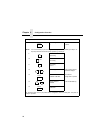
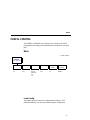
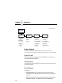
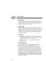
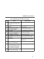
Menu
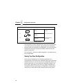
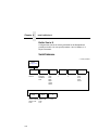
CONFIG. CONTROL
The CONFIG. CONTROL menu allows you to control your printer’s
configurations according to the specifications necessary for your print
jobs.
Menu
* = Factory Default
CONFIG.
CONTROL
(from page 69)
Load Config.
Factory*
1-8
Save Config.
1*
(1-8)
Print Config.
Current*
Factory
Power-up
All
1-8
Delete Config.
1*
(1-8)
Power-up
Config.
Factory*
1-8
Protect
Configs.
Disable*
Enable
Load Config.
The printer can store numerous configurations in memory. This
parameter allows you to select and load a specific configuration.
71
Chapter 4
CONFIG. CONTROL
Save Config.
This option allows you to save up to eight unique configurations to meet
different print job requirements. This eliminates the need to change the
parameter settings for each new job. The configurations are stored in
memory, and will not be lost if you turn off the printer. If the Protect
Configs. parameter is enabled, the new configuration will not be saved
unless the existing configuration has been deleted first. The factory
default configuration cannot be changed. See “Saving Your New
Configuration” on page 66 for details.
Print Config.
This option is used to print a listing of various stored printer
configurations. It is recommended you store printouts of your
configurations in a safe place for quick referral.
Delete Config.
You can delete one or all of your eight customized configurations. The
factory default configuration cannot be deleted.
Power-Up Config.
You can specify which of the nine configurations (Factory or 1-8) will be
the power-up configuration.
Protect Configs.
You can specify whether or not a new configuration should overwrite an
existing configuration when you activate the Save Configs. parameter.
When disabled (default), the new configuration will overwrite the
existing configuration. When enabled, the new configuration will not
overwrite the existing configuration, and the message “CONFIG.
EXISTS / Delete First” displays.
72
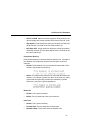
Menu
ACTIVE EMULATION
* = Factory Default
Emulation
1Optional
ACTIVE
EMULATION
(from page 69)
PCL-II*
LP PLUS
IGP/PGL1
IGP/VGL1
The ACTIVE EMULATION function allows you to activate either the
PCL-II or LinePrinter Plus emulation, as well as the optional IGP/PGL or
IGP/VGL emulations, if they are installed. There are two methods for
selecting the desired emulation. The first is by selecting the emulation
directly from the printer menu. The second is by sending a host
command which will switch the emulation automatically (see the
appropriate Programmer’s Reference Manual for details).
When changing from one emulation to the other, the printer will load the
power-up configuration. Thus, any configuration settings performed
before selecting these emulations and not saved in NVRAM will be lost.
IMPORTANT
In order to configure an emulation, the emulation must be selected
in the ACTIVE EMULATION menu. The emulation that is not
selected will not appear in the EMULATION menu (see
“EMULATION” on page 74).
73
Chapter 4
EMULATION
EMULATION
The EMULATION menu is the gateway to configure the emulations
available with your printer. The control codes for each of these
emulations are described in their respective Programmer’s Reference
Manuals.
* = Factory Default
Emulation
1Optional
EMULATION
(from page 69)
PCL-II*
LP PLUS
IGP/PGL1
IGP/VGL1
page 75
page 79
page 93
page 101
PCL-II Emulation
Hewlett-Packard’s Printer Control Language that is compatible with
Compaq systems.
LinePrinter Plus Emulations
•
Epson FX. This LP Plus emulation is provided for compatibility with
the Epson FX-1050 printer control language.
•
Proprinter XL. This LP Plus emulation is provided for compatibility
with the IBM Proprinter III XL printer control language.
•
P-Series. This is the Printronix P-Series printer control language,
provided as part of LP Plus.
Optional Emulations
IGP/VGL (Code V) and IGP/PGL are optional graphics emulations.
They can be selected and configured only if you have purchased these
options. PCL-II must be the active emulation for Code V or IGP/PGL to
operate.
74
PCL-II Emulation
PCL-II Emulation
* = Factory Default
EMULATION
(from page 74)
PCL-II
Primary Char
Set
Secondary
Char Set
Page Length
Rep.
ID
ID
Inches/Page*
0* - 109, xx
0* - 109, xx Lines/Page
Symbol Set
Symbol Set
(see next page) (see next page)
Pitch
Pitch
10*, 12, 13.3
10*, 12, 13.3
15, 16.67, 20
15, 16.67, 20
Density
Density
Data Proc.*
Data Proc.*
NLQ
NLQ
OCR-A
OCR-A
OCR-B
OCR-B
High Speed
High Speed
Display
Functns
Disable*
Enable
Line
Terminator
LF after CR
Disable*
Enable
CR after LF
Enable*
Disable
CR after FF
Enable*
Disable
CR after VT
Enable*
Disable
PTX Linefeed
Disable*
Enable
Page L. Inches
Graphics
Density
60 dpi*
70 dpi
LPI Adjust
6 lpi*
8 lpi
Config. Print
Perforation
Skip
Disable*
Enable
Page L. Lines
66*
(1-128)
Symbol Set
Print
11 inches*
(2-16 inches)
75
Chapter 4
EMULATION
Primary Char
Set
(from page 75)
Secondary
Char Set
(from page 75)
Symbol Set
Symbol Set
Roman-8(8U)*
Turkish-8(8T)
Arabic-8(8V)
Cyrillic(8R)
Japan Postnet
Katakana Post
ASCII(OU)
Math Sym(0A/0M)
LineDraw(0B/0L)
IS0 Den/Nor(0D)
Roman Ext.(0E)
ISO UK(1E)
ISO France(0F)
ISO German(0G)
Hebrew(0H)
Japan ASCII(0K)
Katakana(1K)
Block Char(1L)
OCR-A(0O)
OCR-B(1O)
ISO Swe/Fin(0S)
ISO Spain(1S)
ISO Italian(0I)
ISO Portugu(4S)
Latin-1(0N)
Latin-2(2N)
Latin-5(5N)
Latin-6(6N)
Baltic(19L)
PC8 DanNor(11U)
PC8 Cd437(10U)
PC850 MtLi(12U)
PC851 LtGk(12G)
PC852 Lat2(17U)
PC Turkish(9T)
PC Hebrew(15H)
PC Lat/Ara(10V)
PC Cyrillic(3R)
Win3.1 Lat-1(19U)
Win3.1 Lat-2(9E)
Win3.1 Lat-5(5T)
Math-8(8M)
PS Math(5M)
Greek 7(12N)
Postnet 4(15Y)
Postnet 11.25
Greek-8(8G)
Hebrew-8(8H)
Katakana-8(8K)
(identical to Primary
Character Set)
Primary Character Set
You can select one of 92 pre-defined character sets by ID (although
character sets range from 0 - 109, not all sets are available on the
Compaq series printer), or you can select pitch, symbol set, and
typeface individually. If the combination you choose matches one of the
92 predefined sets, the ID submenu will reflect that selection. If not, the
ID menu will display “xx” to indicate that the current character set does
not match a pre-defined set. Set 0 is the default and its attributes are 10
cpi, Data Processing typeface, and Roman 8 symbol set.
Secondary Character Set
Your printer can store an additional character set. To toggle between
them, send the Shift In (Decimal 15, to select the Primary character set)
or Shift Out (Decimal 14, to select the Secondary character set)
command code.
76
PCL-II Emulation
Page Length Representation
•
Inches/Page. All page length calculations are based on the inches
displayed on the panel.
•
Lines/Page. All page length calculations are based on the number
of lines per page displayed on the panel.
For example, if the form in use is 82 lines at 6 lpi, the page is
physically 13.67 inches. Since 13.67 inches is not selectable from
the Length in Inches menu, change the representation to lines, then
set the number of lines to 82. The inches menu will display 13.6
inches although the printer internally keeps the exact form length of
13.67 inches.
Graphics Density
Graphics can be printed in 60 DPI (the default) or 70 DPI.
Perforation Skip
•
•
Disable. Allows printing on page perforation.
Enable. The printer sets up a skip-over margin to prevent printing
on the page perforation.
Display Functions
•
•
Disable. The default. Control characters are not printed.
Enable. Control characters are printed before they get executed.
This is a useful debugging tool.
Line Terminator
You can specify what will be used to indicate the end of a line. Four
options are available: LF after CR, CR after LF, CR after FF, and CR
after VT. Each of these options may be Enabled or Disabled
independent of one another.
77
Chapter 4
EMULATION
PTX Linefeed
•
Disable. The default. Linefeed is performed as calculated from the
bottom of the graphics or barcode, thereby disrupting the vertical
text alignment.
•
Enable. The Linefeed moves to the next line as calculated from the
Top of Form position, thereby retaining vertical text alignment.
When printing graphics or bar codes, you may want to set the PTX
Linefeed parameter to Enable to maintain text alignment.
PTX Linefeed Enabled
LINE 1
LINE 1
LINE 2
PTX Linefeed Disabled
Linefeed
LINE 3
LINE 2
Linefeed
LINE 3
LPI Adjust
This parameter lets you specify the lines per inch (lpi) values, 6 LPI (the
default) or 8 LPI.
Page Length Adjust/Lines
This parameter lets you set physical page length from 1 to 128 lines.
The default is 66 lines.
Page Length Adjust/Inches
This parameter lets you set physical page length from 2 to 16 inches, in
increments of half an inch. The default is 11 inches.
Config. Print
This option prints the emulation’s parameters and the currently selected
values.
Symbol Set Print
This option prints a list of all the available sets. The character set
number prints to the left of the character set sample.
78
LinePrinter Plus Emulation
LinePrinter Plus Emulation
* = Factory Default
EMULATION
(from page 74)
LinePrinter+
Printer
Protocol
Print Char. Set
P-Series
(see page 83)
Proprinter XL
(see page 87)
Epson FX
(see page 90)
CPI/LPI Select
Font Attributes
Select CPI
10.0 CPI*
12.0 CPI
13.3 CPI
15.0 CPI
17.1 CPI
20.0 CPI
Select LPI
6.0 LPI*
8.0 LPI
10.3 LPI
(see below)
Page Format
(see next page)
Font Attributes
(from above)
Typeface
Prop. Spacing
Data Process.* Disable*
NLQ
Enable
OCR-A
OCR-B
High Speed
NLQ Sans Serif
Bold Print
Disable*
Enable
Italic Print
Slashed Zero
Disable*
Disable*
Forward Slant Enable
Backward Slant
79
Chapter 4
EMULATION
* = Factory Default
Page Format
(from page 79)
Margins
Perforation
Skip
Left Margin
0* columns
(0-369)
Right Margin
0* columns
(0-369)
Bottom Margin
0* lines
(0-451)
Disable*
1/2 inch
2/3 inch
5/6 inch
1 inch
Form Length
Form Width
Abs. Width IN
Abs. Length IN
13.6* inches
11.0* inches
(0.1-13.6)
(0.1-24)
Abs. Width MM
Abs. Length MM
345.4* millimeters
279.4* millimeters
(0.1-345.4)
(0.1-609.6)
Funct. of CPI
Funct. of Lines
136* Characters
66* lines
(1-272)
(1-192)
Printer Protocol
Select the LinePrinter+ protocol you wish to use. Refer to the
LinePrinter Plus Programmer’s Reference Manual for more information.
Print Char Set
When this selection is displayed and the ENTER key is pressed, the
current character set is printed.
CPI/LPI Select
This parameter lets you specify the characters per inch (cpi) and lines
per inch (lpi) values.
Font Attributes
Typefaces
80
•
Data Processing. A general purpose font printing at 120 dpi
horizontally and 72 dpi vertically. The width of the font varies with
each cpi.
•
NLQ. A high quality font with serifs printing at 180 dpi horizontally
and 96 dpi vertically. The width of the font varies with the cpi.
LinePrinter Plus Emulation
•
OCR-A / OCR-B. Optical character recognition fonts printing at 120
dpi horizontally and 144 dpi vertically. Both fonts print only at 10 cpi.
•
High Speed. A draft quality font printing at 120 dpi horizontally and
48 dpi vertically. The width of the font varies with the cpi.
•
NLQ Sans Serif. A high quality font printing at 180 dpi horizontally
and 96 dpi vertically. This font prints without serifs. The width of the
font varies with the cpi.
Proportional Spacing
Each printed character is contained inside a character cell. The width of
the character cell includes the character and the space around the
character.
•
Disable. Each character cell is printed with the same width. Each
column in the printed text will line up.
•
Enable. The width of each character cell varies with the width of the
character. For example, [i] takes less space to print than [m]. Using
proportional fonts generally increases the readability of printed
documents, giving text a typeset appearance.
Bold Print
•
•
Disable. Text is printed normally.
Enable. Text is printed with a heavy line thickness.
Italic Print
•
•
•
Disable. Text is printed normally.
Forward Slant. Text is printed with a forward slant.
Backward Slant. Text is printed with a backward slant.
81
Chapter 4
EMULATION
Slashed Zero
This parameter allows you to print the numeral “0” with or without the
slash. This option applies to all character sets except OCR-A and
OCR-B.
•
•
Disable. Zero is printed without a slash.
Enable. Zero is printed with a slash.
Page Format
Margins
•
Left Margin. Set in columns. Column zero is defined as the far left
edge of the page, and column numbering increments from left to
right.
•
Right Margin. Set in columns. Column zero is defined as the far
right edge of the page, and column numbering increments from
right to left.
•
Bottom Margin. Defined in lines, starting from line zero at the
bottom of the page and incrementing from the bottom up.
Perforation Skip
•
•
Disable. Allows printing on page perforation.
You may set up a skip-over margin of 1/2 inch, 2/3 inch, 5/6 inch, or
1 inch. For example, a skip-over margin of 1 inch allows a 1 inch
margin at the bottom of the page.
Forms Length
Forms length is the number of lines that can be printed on a page. You
can set forms length in inches, millimeters (mm), or as a function of the
current LPI (lines per inch).
Forms Width
The forms width can be specified in inches, millimeters, or as a function
of the current CPI (characters per inch). The forms width set should not
exceed the actual paper width.
82
P-Series Emulation
P-Series Emulation
* = Factory Default
Printer
Protocol
(from page 79)
P-Series
Control Code
06
6.0 LPI
8.0 LPI*
10.3 LPI
Select SFCC
1*
(hex 00-7F)
Control Code
08
Elongated*
Backspace
EVFU Select
Enable*
Disable
IBM PC*
Define CR
Code
CR = CR*
CR = CR + LF
Disable*
Enable
Alt. Set 80-9F
Character Set
Control Code*
Printable
Multinational
Primary Subset Extended Subset
ASCII (USA)*
ASCII (USA)*
Code Page 437* EBCDIC
French
Code Page 850
German
English
Danish
Swedish
Italian
Spanish
Japanese
French Canadian
Latin American
Norwegian
Danish II
Spanish II
Latin Am II
OCR-A
OCR-B
Auto LF
Latin 2 8859-2
Overstrike
Enable*
Disable
Define LF
Code
LF = CR + LF*
LF = LF
SFCC d
Command
Even dot plot*
Double High
ECMA Latin 1
Primary Subset
ASCII (USA)*
German
Swedish
Danish
Norwegian
Finnish
English
Dutch
French
Spanish
Italian
Turkish
Japanese
Latin 2 852
DEC
Multinational
Extended Subset
Multinational*
Barcode 10 CPI
Mult. DP 10 CPI
Mult. DP 12 CPI
Mult. LQ 10 CPI
Greek DP 10 CPI
Greek DP 12 CPI
Greek LQ 10 CPI
Grap. DP 10 CPI
Grap. LQ 10 CPI
Sci. DP 10 CPI
Sci. DP 12 CPI
Sci. LQ 10 CPI
ASCII (USA)*
French
German
English
Norweg./Danish
Swedish
Italian
Spanish
Japanese
French Canadian
Dutch
Finnish
Swiss
Bulgarian
83
Chapter 4
EMULATION
Control Code 06
Control Code 06 defines the function of ASCII code hex 06 (ACK). You
can select an alternate line spacing of 6, 8 or 10.3 LPI.
Control Code 08
Control Code 08 defines the function of ASCII code hex 08 (BS). You
can define the code to output an elongated character or a backspace.
Define CR Code
This option controls the action of the printer when it receives a Carriage
Return code (hex 0D) from the host computer. If this feature is enabled,
each time the printer receives a Carriage Return, it inserts an additional
Line Feed code (hex 0A) into the data stream. Do not use this feature if
the host computer sends Line Feeds to the printer.
•
CR = CR. Does not insert an extra Line Feed after each Carriage
Return.
•
CR = CR + LF. Inserts an extra Line Feed after each Carriage
Return. The next print position will be print position 1 of the next
line.
Auto LF
This option defines the printer action when print data is received past
the forms width setting.
•
•
84
Disable. Discards any data past the forms width.
Enable. Performs an automatic carriage return and line feed when
data is received past the forms width.
P-Series Emulation
Overstrike
•
Enable. Common dots appear darker in characters printed over
each other, as shown below. The print position moves one-half dot
to the right. Overstrike printing occurs at a decreased speed.
•
Disable. If you are using a control code for overstrike, but it is
disabled in the printer control panel, no bolding will occur.
Define LF Code
•
LF = CR + LF. Forces an automatic carriage return with each line
feed command. The next print position is print position 1 of the next
line.
•
LF = LF. Does not perform an automatic carriage return. The next
print position will be the current print position of the next line.
Select SFCC
This parameter allows you to select which ASCII codes will function as
the Special Function Control Code (SFCC) command delimiter.
P-Series codes can use hex 00 through hex 7F. Options include the
following:
•
•
•
•
•
ESC (hex 1B)
SOH (hex 01)
ETX (hex 03)
CIRCUMFLEX (hex 5E)—also called caret (^)
TILDE (hex 7E)—(~)
NOTE: SOH, ETX and ESC are non-printables. The characters (^) and
(~) are printable; however, do not use them as printables in the
host data stream if either is chosen as a delimiter, or print
errors will occur.
85
Chapter 4
EMULATION
EVFU Select
Controls how the printer handles vertical formatting.
•
Enable. Enables the VFU and selects P-Series compatible
Electronic Vertical Format Unit (EVFU).
•
Disable. Disables all VFU processing.
Alt. Set 80-9F
Determines whether the printer processes ASCII codes hex 80 through
hex 9F as control codes or as printable characters.
Character Set
Specifies a character set. To use one of these sets, choose the desired
set and press ENTER. Two groups of character sets (IBM PC and
ECMA Latin 1) have Primary and Extended Subsets. To use one of
these sets, choose the group name and press ENTER, then choose the
desired set within the Primary or Extended subset and press ENTER.
Both the group and the desired set will be starred to indicate your
selection.
SFCC d Command
86
•
Even dot plot. This option interprets SFCC d Command as even
dot plot.
•
Double high. This option interprets SFCC d Command as double
high. Select this option for backward compatibility.
Proprinter XL Emulation
Proprinter XL Emulation
* = Factory Default
Printer
Protocol
(from page 79)
Proprinter XL
Define CR
Code
CR = CR*
CR = CR + LF
Auto LF
Enable*
Disable
Define LF
Code
LF = LF*
LF = CR + LF
FF Valid at
TOF
Enable*
Disable
Character Set
Alt. Char Set
Code Page 437* Set 1*
Code Page 850 Set 2
OCR-A
OCR-B
Latin 2 8859-2
Latin 2 852
Bulgarian
Latin 0 8859-15
20 CPI
Condensed
Enable*
Disable
Define CR Code
This option controls the action of the printer when it receives a Carriage
Return code (hex 0D) from the host computer. If this feature is enabled,
each time the printer receives a Carriage Return, it inserts an additional
Line Feed code (hex 0A) into the data stream. Do not use this feature if
the host computer sends Line Feeds to the printer.
•
CR = CR. Does not insert an extra Line Feed after each Carriage
Return.
•
CR = CR + LF. Inserts an extra Line Feed after each Carriage
Return.
87
Chapter 4
EMULATION
Auto LF
This option defines the printer actions when print data is received past
the forms width setting.
•
Enable. Performs an automatic carriage return and line feed when
data is received past the forms width.
•
Disable. Discards any data past the forms width.
Define LF Code
•
LF = LF. Does not perform an automatic carriage return when a line
feed command is received. The next print position will be the
current print position of the next line.
•
LF = CR + LF. Forces an automatic carriage return with each line
feed command received. The next print position is print position 1 of
the next line.
FF Valid at TOF
•
Enable. Performs a form feed when the host sends a Form Feed
command and the printer is at the top of form.
•
Disable. Will not perform a form feed when the host sends a Form
Feed command and the printer is at the top of form.
Character Set
Specifies a character set. To use one of these sets, choose the desired
character set and press ENTER.
88
Proprinter XL Emulation
Alternate Char Set
This option determines if data in the range of hex 80 through hex 9F
should be interpreted as a control code or as a printable character.
•
Set 1. Interprets data in the range of hex 80 through hex 9F as a
control code.
•
Set 2. Prints data for the characters at hex locations 03, 04, 05, 06,
15 and 80 through 9F.
20 CPI Condensed
Compressed print characters are narrower than the normal character
set. This is helpful for applications where you need to print the
maximum amount of information on a page.
•
Enable. Prints characters about 60 percent the width of normal
characters when compressed print is chosen by the host computer.
•
Disable. Does not compress print widths, even if condensed print is
chosen by the host.
89
Chapter 4
EMULATION
Epson FX Emulation
* = Factory Default
Printer
Protocol
(from page 79)
Epson FX
Define CR
Code
CR = CR*
CR = CR + LF
Alt. Set 80-9F
Control Code*
Printable
90
Auto LF
Enable*
Disable
Define LF
Code
LF = LF*
LF = CR + LF
Printer Select
Disable*
Enable
Character Set
20 CPI
Condensed
Epson Set*
Enable*
ASCII (USA)* Disable
French
German
English
Danish I
Swedish
Italian
Spanish I
Japanese
Norwegian
Danish II
Spanish II
Latin Am I
French Canadian
Latin Am II
OCR-A
OCR-B
Latin 2 8859-2
Latin 2 852
Cyrillic 866
Bulgarian
Latin 0 8859-15
Epson FX Emulation
Define CR Code
The Define CR Code option controls the action of the printer when it
receives a Carriage Return code (hex 0D) from the host computer. If
this feature is enabled, each time the printer receives a Carriage
Return, it inserts an additional Line Feed code (hex 0A) into the data
stream. Do not use this feature if the host computer sends Line Feeds
to the printer.
•
CR = CR. Does not insert an extra Line Feed after each Carriage
Return.
•
CR = CR + LF. Inserts an extra Line Feed after each Carriage
Return.
Auto LF
This option defines the printer actions when print data is received past
the forms width setting.
•
Enable. Performs an automatic carriage return and line feed when
data is received past the forms width.
•
Disable. Discards any data past the forms width.
Define LF Code
The Define LF Code option controls the action of the printer when it
receives a Line Feed code (hex 0A) from the host computer. If this
feature is enabled, each time the printer receives a Line Feed, it inserts
an additional Carriage Return code (hex 0D) into the data stream. This
feature is required if the host computer does not send Carriage Returns
to the printer.
•
•
LF = LF. Does not add a Carriage Return with a Line Feed.
LF = CR + LF. Adds an extra Carriage Return with each Line Feed.
Printer Select
•
•
Disable. Ignores the ASCII DC1 and DC3 control codes.
Enable. Disables the printer when a DC1 control code is received,
and enables the printer when a DC3 control code is received.
91
Chapter 4
EMULATION
Character Set
Specifies a character set. To use one of these sets, choose the desired
character set and press ENTER.
Note that when OCR-A or OCR-B is selected as the print language, the
Font Attribute Typeface option under the LinePrinter Plus menu (page
80) is changed to OCR-A or OCR-B, respectively.
20 CPI Condensed
Compressed print characters are narrower than the normal character
set. This is helpful for applications where you need to print the
maximum amount of information on a page.
•
Enable. Prints about 60 percent of the width of normal characters
when compressed print is chosen by the host computer. For
example, a 12 CPI Draft font will compress to 20 CPI.
•
Disable. Does not compress print widths, even if condensed print is
chosen by the host.
Alternate Set 80-9F
92
•
Control Code. Interprets data in the range of hex 80 through hex
9F as a control code.
•
Printable. Prints data in the range of hex 80 through hex 9F.
IGP/PGL Submenu
IGP/PGL Submenu
The IGP/PGL emulation is the software based Intelligent Graphics
Processor (IGP). It is based upon, and is compatible with, the Printronix
IGP-100/200/400 board using the Printronix Graphics Language (PGL).
The IGP/PGL graphics processing features are detailed below.
Features
On-Line Form and Label Generation makes it easy to create forms or
labels with a “preprinted” look for each application. IGP/PGL programs
control all graphic functions, dramatically reducing host computer
programming and processing time.
Graphic capabilities include boxes, vertical and horizontal lines with
user-selectable thickness, logos, and special alphanumeric print
features. Forms and graphic designs can be duplicated horizontally and
vertically.
Alphanumeric data can appear as prepositioned “fixed” information
(entered when the form is created), be overlayed onto the form
(positioned in a specific location after the form is created), or may be
dynamically merged with the form.
Selectable Bar Codes provide you with the appropriate bar code for
your application using standard wide-to-narrow ratios. A wide selection
of bar codes are available: Codabar, Code 39, Code 93, Code 128
Subset A, B, and C, EAN 8, EAN 13, FIM, Interleaved 2 of 5, German I2/5, ITF-14, Matrix, MSI A through D, PDF417, POSTNET, PostBar,
Royal Mail, UCC/EAN-128, UPC-A, UPC-E, and UPS 11. UPC and
EAN bar codes can specify add-on data.
Expanded and Compressed Character Print attract attention where
needed. Alphanumeric height and width are controlled independently
for a wide range of character sizes up to 139 times the standard
character size (up to 11.3 inches wide and tall). Compressed print sizes
of 10, 12, 13, 15, 17 and 20 characters per inch (cpi) are available.
Logos are created using alphanumeric commands and add many print
and shading features for a “customized” appearance to forms, reports,
and labels.
93
Chapter 4
EMULATION
Rotated Alphanumerics permit new concepts in form design. Normal,
expanded, and compressed character strings can be rotated 90
degrees clockwise or counterclockwise, or they can be printed upside
down.
Reversed Print permits highlighting and contrasting by printing white
characters on a dark background.
Automatic Increment/Decrement Capability allows batch form
processing. You can identify individual numeric and bar code data
fields, which includes automatic increment or decrement functions.
Scaling Capability permits graphic elements, such as corners or
boxes, to retain their physical shapes and sizes when printed in a
horizontal and vertical density other than the base density of 60 x 72
dpi.
Multinational Character Sets provide 32 international character sets,
each 96 characters in length. This feature also allows you to create your
own character sets using characters defined and stored in memory.
Configuring the Emulation with the Control Panel
You can select IGP/PGL default parameters directly from the control
panel, or by control codes as explained in the IGP/PGL Programmer’s
Reference Manual. The IGP/PGL parameters are described on the
following pages. Parameters marked with an asterisk (*) indicate the
default value. The printer must be offline to enter the configuration
structure.
Pressing an invalid key to enter a parameter value may move you to
another level in the configuration or exit the configuration menu
completely. Configure the IGP/PGL according to your specific
requirements.
IMPORTANT
94
BEFORE you reconfigure the IGP/PGL, print a configuration sheet
to see all of the current settings.
IGP/PGL Submenu
* = Factory Default
EMULATION
(from page 69)
IGP/PGL
Define CR
Code
CR = CR*
CR = CR + LF
Select Font
0-32
UPC
Descenders
Enable*
Disable
Define LF
Code
LF = LF*
LF = CR + LF
Select LPI
6*
8, 9, 10
Compressed
CPI
Disable*
Enable
Autowrap
Disable*
Enable
Auto
Uppercase
Disable*
Enable
Ignore Char
Ignore Mode
Disable*
Enable
Select Char
0*
(0-255)
Select SFCC
126*
(1-255)
Skip Cmd
Prefix
Enable*
Disable
IGP100
Compatbl.
Disable*
Enable
PI Slew Range
16*
15
Power On
IGP/PGL
Enable*
Disable
CR Edit
Disable*
Enable
Ext Execute
Copy
Disable*
Enable
Optimized
Ratio
Disable*
Enable
95
Chapter 4
EMULATION
Define CR Code (Carriage Return)
This parameter forces the printer to insert an automatic Line Feed code
into the data stream whenever a Carriage Return code occurs. This is
to be used only if the host computer does not send Line Feeds to the
printer.
•
CR = CR. Does not perform a line feed. The next print position will
be print position 1 of the current line.
•
CR = CR + LF. Performs an automatic line feed. The next print
position will be print position 1 of the next line.
Define LF Code (Line Feed)
This parameter forces the printer to insert an automatic Carriage Return
code into the data stream whenever a Line Feed code occurs. This can
be used in most installations, but it is required if the host computer does
not send Carriage Returns to the printer.
•
LF = LF. Does not perform an automatic carriage return. The next
print position will be the current print position of the next line.
•
LF = CR + LF. Performs an automatic carriage return. The next
print position will be print position 1 of the next line.
Autowrap
This parameter determines if text will wrap to the next line when the line
of text exceeds the right margin.
•
Disable. Truncates the text beyond the right margin until a CR or
CR + LF is received.
•
Enable. Automatically inserts a CR + LF after a full print line.
Select SFCC
You can specify which decimal code (1-255) will be used as the Special
Function Control Code (SFCC). The factory default setting is 126. The
SFCC denotes that the following data is an IGP/PGL command.
96
IGP/PGL Submenu
PI Slew Range
You can specify how many lines the paper will feed.
•
15. A paper slew of 1-15 will move 1-15 lines. A paper slew of 0 will
move 1 line.
•
16. A paper slew of 0-15 will move 1-16 lines.
CR Edit
This parameter determines if a carriage return will be followed by a line
feed.
•
Disable. The printer ignores all carriage returns that are not
followed by line feeds.
•
Enable. The printer processes all carriage returns, even for those
that are not followed by line feeds.
Select Font
This parameter allows you to select a font for the IGP/PGL feature. The
default is 0, which is U.S. ASCII. The following values are valid choices:
0
1
2
3
4
5
6
7
8
9
10
11
U.S. ASCII
German
Swedish
Danish
Norwegian
Finnish
English
Dutch
French
Spanish
Italian
Turkish
Values 12-23 are undefined and will default to 0. You can set values 2432 to specific fonts; refer to the USET command in the IGP/PGL
Programmer’s Reference Guide.
97
Chapter 4
EMULATION
Select LPI
This is the number of lines to be printed per inch. For example, at 6 lpi
there is 1/6 inch from the top of one print line to the top of the next print
line.
Auto Uppercase
This parameter enables the printer to print text in all uppercase when
using the ALPHA command.
•
•
Disable. The printer will print text in upper and lowercase.
Enable. The printer will print text in uppercase only.
Skip Command Prefix
This parameter determines if the printer will print any data before an
IGP/PGL command is received.
•
Enable. The printer ignores all data on the current line before an
IGP/PGL command.
•
Disable. The printer will print all data on the current line before an
IGP/PGL command.
Power On IGP/PGL
You can set the IGP/PGL feature so that it is enabled or disabled when
the printer is powered on.
98
•
Enable. The IGP/PGL is enabled when the printer is powered on.
(The IGP/PGL feature is initialized in the Normal mode.)
•
Disable. The IGP/PGL is disabled when the printer is powered on.
(The IGP/PGL feature is initialized to the Quiet mode.)
IGP/PGL Submenu
Extended Execute Copy
•
Disable. Dynamic data, overlay data, etc. are not allowed if the
optional Form Count parameter (number of forms to print) is
specified as part of the Execute command. (This setting is IGP-100
compatible.)
•
Enable. Dynamic data, overlay data, etc. are allowed within a form
in which the Form Count parameter is specified in the Execute
command. In this case, the exact same form (with identical dynamic
data, etc.) is printed for whatever the Form Count is. However,
incremental data is not incremented since the page that is printing
is exactly the same. Also, each form is printed on a separate page.
UPC Descenders
This parameter allows you to print bar code descenders when human
readable data is not presented in the UPC/EAN bar codes.
•
Enable. UPC/EAN bar codes are printed with descenders, even if
there is no human readable data.
•
Disable. UPC/EAN bar codes are printed without descenders if
there is no human readable data.
Compressed CPI
This parameter allows you to choose a compressed character (60%
shorter) for 17 or 20 CPI instead of the normal height character.
•
•
Disable. The IGP/PGL does not use compressed 17 or 20 CPI font.
Enable. Uses the standard compressed 17 or 20 CPI font.
Ignore Character
Ignore Mode
This parameter instructs the IGP/PGL to ignore the character selected
under the Select Character menu.
•
•
Disable. The IGP/PGL does not ignore any characters.
Enable. The IGP/PGL ignores the characters specified in the
Select Character menu.
99
Chapter 4
EMULATION
Select Character
Instructs the IGP/PGL which decimal character (0-255) to ignore from
the host.
IGP100 Compatbl.
This option instructs the IGP/PGL to behave similar to the IGP-100 with
respect to certain commands. All new users with new applications
should select the “Disable” option. Selecting this mode insures the
printer behaves as described in this manual.
•
•
Disable. The IGP/PGL does not emulate the IGP-100 mode.
Enable. The IGP/PGL emulates the IGP-100 version.
Optimized Ratio
This option selects different bar code ratios for certain bar codes
including Code 39 and Interleaved 2 of 5. It is included for compatibility
with the IGP-X00 printers.
•
•
100
Disable. Use standard bar code ratios.
Enable. Select the alternate bar code ratios.
IGP/VGL Emulation
IGP/VGL Emulation
Code V Graphics language (VGL) is an Intelligent Graphics Printing
(IGP) software emulation designed for your line matrix printer. The IGP
Code V emulation of the QMS Code V Version II programming
language produces on-line forms, bar codes, and alphanumeric textgeneration. The graphics processing features are detailed below.
Features
On-Line Form and Label Generation makes it easy to create forms or
labels with the “preprinted” look for each application. VGL programs
control all graphics functions, dramatically reducing host computer
programming and processing time. Graphics capabilities include boxes,
vertical and horizontal, solid and dashed lines with a variety of
thickness, logos, and special alphanumeric print features.
Variable Bar Codes allow the bar code for your application to print with
standard or user-defined ratios in vertical or horizontal orientations.
Available bar codes are: Codabar, Code 39, Code 93, Code 128 with
Subsets A, B, and C, EAN 8, EAN 13, Identicon, Interleaved 2 of 5,
MSI, UPC-A, UPC-E, POSTNET, Royal Mail, UCC/EAN 128, UPS 11,
and UPC Shipping. POSTNET is available only in the horizontal
direction. A dark print mode is included for darker, high-contrast bar
codes. The IBARC bar code command prints bar codes in four
orientations: horizontal, rotated 90, rotated 180 or rotated 270 degrees.
Expanded and Compressed Print draws attention where needed.
Alphanumeric height and width are controlled independently for a
tremendous range of character sizes up to 9.9 inches wide and tall.
Several compressed print sizes are available: 12, 13.33, 15, 17.65, and
20 cpi (characters per inch), permitting up to 170 columns in an 8.5 inch
printed area (20 cpi).
Rotated Alphanumerics permit new concepts in form design. Normal,
expanded, and compressed character strings can be rotated 90
degrees clockwise, counterclockwise, or printed upside down.
101
Chapter 4
EMULATION
Logos are easily created using alphanumeric commands and a variety
of print and shading features, providing a “customized” appearance for
forms, reports, and labels. The registered trademark, copyright, TUV ®,
GS-Mark, UL®, and CSA® symbols are provided as standard designs
on the Code V, and you can also define custom symbols.
Reverse and Shaded Print permit highlighting and contrasting by
printing white characters on a dark background or white characters on a
gray, shaded background. Various levels or patterns of gray shading
and reverse printing may combine with the many other print features to
create distinctive designs.
Automatic Increment/Decrement Capability allows batch form
processing. Individual alphabetic, numeric, and bar code data fields can
be identified and automatically incremented or decremented by any
amount, beginning from a specified reference point.
Standard Character Sets provide you with many different character
sets. Based on the Multinational Character Set, you may create your
own character sets using characters defined and stored in flash
memory.
Configuring the Emulation with the Control Panel
You can select Code V default parameters directly from the control
panel, or by control codes as explained in the IGP/VGL Programmer’s
Reference Manual. The Code V parameters are described on the
following pages. Parameters marked with an asterisk (*) indicate the
default value. The printer must be offline to enter the configuration
structure.
Pressing an invalid key to enter a parameter value may move you to
another level in the configuration or exit the configuration menu
completely. Configure the IGP/VGL according to your specific
requirements.
IMPORTANT
102
BEFORE you reconfigure the IGP/VGL, print a configuration sheet
to see all of the current settings.
IGP/VGL Emulation
* = Factory Default
EMULATION
(from page 69)
CODE V
SFCC & Pwrup
LPI
Control Character 6*
94* (17-255)
7, 8, 9, 10
Ignore Mode
Disable*/Enable
Free Format
Disable*/Enable
Mgnum Conversion
Disable*/Enable
ISO Char Set
0-32
Graphics
Options
(see next page)
Error Handling
Ignore/DB8
Setup
Ignore Nulls
Error Msgs
Disable*/Enable
Enable*/Disable
Data Bit 8
Error Markers
Enable*/Disable
Enable*/Disable
Offpage Errors
Disable*/Enable
Barcode Errors
Enable*/Disable
PI Control
Printer PI
Disable*/Enable
Host PI
Disable*/Enable
Max PI 16
Enable*/Disable
103
Chapter 4
EMULATION
Graphics
Options
(from page 103)
Slashes in
Zeros
Enable*
Disable
UPC
Descenders
Disable*
Enable
Ignore Dots
Append
Rotated
Disable*
Enable
Disable*
Enable
Rot. Char Size
Ignore Spaces
Adjusted*
Not Adjusted
Disable*
Enable
Truncate Alpha
True Vert 1/10
Enable*
Disable
Disable*
Enable
Midline PY
Disable*
Enable
Convert to U/C
Disable*
Enable
Absorb After
^PY
Absorb All*
Absorb Motion
Disable
Absorb After
^PN
Disable*
Enable
IGP 110
Compatbl.
Disable*
Enable
SFCC & Pwrup
This option has several suboptions which define the SFCC and powerup configuration used with Code V.
Control Character
This option selects the Special Function Control Code (SFCC). The
default value is the caret ^ (decimal 94). Valid values are 17 through
255. Throughout this section, the caret is used as the SFCC. Run a
configuration printout to determine the currently selected SFCC.
104
IGP/VGL Emulation
Ignore Mode
•
•
Disable. The default.
Enable. Selects the ignore mode as the power-up default, and
selects the graphics mode ^PY as the power-up default. All
characters are ignored until a ^A command is received.
Free Format
•
•
Disable. The default.
Enable. Selects free format mode as the power-up default, and
selects the graphics mode ^PY as the power-up default. Free
format causes the Code V to ignore carriage returns, line feeds and
all characters below hex 20 sent from the host.
Mgnum Conversion
•
•
Disable. The default.
Enable. Selects the graphics mode ^PY as the power-up default.
LPI
The number of lines to be printed per inch. For example, at 6 lpi there is
1/6 inch from the top of one print line to the top of the next print line.
Graphics Options
Following are several options which configure printing output.
Slashes in Zeros
This parameter allows you to print the numeral “0” with or without the
slash. This option applies to all character sets except OCR-A and OCRB.
•
•
Disable. Zero is printed without a slash.
Enable. Zero is printed with a slash.
105
Chapter 4
EMULATION
Ignore Dots
•
•
Disable. The default.
Enable. Causes the Code V to expect position values to be
specified in only 1/10ths of an inch. If the dot position is also given,
it is treated as text.
Append Rotated
•
Disable. Logos and alphanumeric strings are treated as separate
elements.
•
Enable. Appends logos to an alphanumeric string rotated in a
clockwise, counterclockwise, or inverted orientation.
Truncate Alpha
When enabled, this parameter prevents the printing of Error 48
(Element Off Page Error) if alphanumeric data, including spaces,
extends beyond the right side of the form.
True Vert 1/10
•
Disable. A vertical 1/10 of an inch parameter is used as 7/72 of an
inch. The absolute move is slightly smaller than expected. For
example, a one inch move would be 70/72 of an inch. Vertical
moves that have the same value will be identical in length.
•
Enable. A vertical 1/10 of an inch parameter is used as 1/10 of an
inch. Rounding occurs to the nearest 1/72 of an inch. This can
cause vertical moves that have the same value to differ by ± 1/72 of
an inch.
Absorb after ^PY
106
•
Absorb All. The system ignores all the data and terminator until a
host generated terminator is detected.
•
Absorb Motion. Prevents paper motion following a system
terminator in a graphics ^PY command.
•
Disable. System terminators following a graphics command are
sent to the printer and result in paper motion.
IGP/VGL Emulation
UPC Descenders
•
Disable. UPC/EAN bar codes are printed without descenders if
there is no human readable data.
•
Enable. UPC/EAN bar codes are printed with descenders, even if
there is no human readable data.
Rot. Char Size
•
Adjusted. Rotated (clockwise/counterclockwise), expanded
characters have a different size than an unrotated character with
the same size parameters.
•
Not Adjusted. Rotated, expanded characters will be the same size
as unrotated characters with the same size parameters.
Ignore Spaces
•
Disable. Trailing spaces are not deleted from alphanumeric
elements in a graphics pass.
•
Enable. Trailing spaces are deleted from alphanumeric elements in
a graphics pass.
Midline PY (includes ^PN)
•
Disable. The Graphics mode Enable command, ^PY, must be the
first three characters of a line.
•
Enable. The ^PY or ^PN can occur anywhere in a line.
Convert to U/C
•
•
Disable. Lowercase characters are printed normally.
Enable. All lowercase alphabetic characters are converted to
uppercase.
107
Chapter 4
EMULATION
Absorb After ^PN
•
Disable. All line terminators that immediately follow the ^PN
command are sent to the printer and processed.
•
Enable. All line terminators that immediately follow the ^PN
command are ignored.
IGP 110 Compatbl.
This option instructs the Code V to behave similar to the IGP-110 with
respect to certain commands. All new users with new applications
should select the “Disable” option. Selecting this mode insures the
printer will behave as described in this manual.
•
•
Disable. The Code V does not emulate the IGP-110 mode.
Enable. The Code V emulates the IGP-110 version.
Error Handling
Following are several options which define how errors are reported.
Error msgs
•
Enable. Command syntax is checked and error messages printed
when command parameters are incorrect.
•
Disable. Error checking and error messages are suppressed.
Error markers
•
Enable. Prints the following error markers for those elements that
print beyond the page boundaries:
>> for elements that begin off the right side of the page;
<< for elements that begin at the indicated position but end off the
page;
♦ for elements where the starting position of the command
contains an error other than an off-page error.
108
IGP/VGL Emulation
Offpage Errors
•
Disable. Does not report errors for elements that start or end
beyond the right edge of the page.
•
Enable. Reports errors for elements that start or end beyond the
right edge of the page.
Barcode Errors
•
Enable. An error message will print when invalid bar code data is
encountered.
•
Disable. Code V will not print an error for illegal bar code data; the
bar code will be skipped.
NOTE: When Barcode Errors is disabled, the Code V emulation will try
to make the best use of invalid data by either truncating extra
digits or adding zeros to the end of bar code data to meet
minimum data length requirements for some bar codes. Not all
errors will be corrected.
Ignore / DB8 Setup
Following are several options which define character filtering and data
bit 8.
Ignore Nulls
•
Disable. None of the null characters (hex 00 or hex 80) are
ignored.
•
Enable. Null characters are filtered out of the data stream.
Data Bit 8
•
Enable. The PI line is not passed directly from host to printer; all 8
bits are used for data bits, and characters in the hex 80-FF range
can be accessed.
•
Disable. When the host PI line is enabled, data bit 8 internally
indicates PI line status. To use the PI line, disable data bit 8, and
enable the Host PI configuration option (under the PI Control
option, below).
109
Chapter 4
EMULATION
NOTE: Data bit 8 is interpreted as either data bit 8 or PI signal, but
never both. When enabled as data bit 8, data bit 8 has priority
over the PI signal, and all data above hex 7F is used to access
character data and not to interpret PI line data.
Conversely, when data bit 8 is disabled and the PI signal is
used, data bit 8 of the data is reserved for use as the PI
function, and you cannot access characters in the hex 80-FF
range. Therefore, to access characters in the hex 80-FF range,
data bit 8 must be enabled.
ISO Char Set
This parameter allows you to select a font for the Code V feature. The
default is 0, which is U.S. ASCII. The following values are valid choices:
0
1
2
3
4
5
6
7
8
9
10
U.S. ASCII
United Kingdom
Swedish/Finnish
Norwegian/Danish
Japanese
German
French
Italian
Spanish
PC Subset
Code V Version I
Values 11-23 are undefined and will default to 0. You can set values 2432 to specific fonts; refer to the User Set command in the IGP/VGL
Programmer’s Reference Guide.
PI Control
Printer PI
110
•
Disable. The ASCII emulation is configured with the PI line
disabled.
•
Enable. The ASCII emulation is configured with the PI line enabled.
IGP/VGL Emulation
Host PI
•
•
Disable. The host does not send PI signals.
Enable. The host sends PI signals. The Data Bit 8 configuration
option must be disabled to transmit the PI line to the printer.
Max PI 16
•
•
Enable. A paper slew of 0-15 will move 1-16 lines.
Disable. A paper slew of 1-15 will move 1-15 lines. A paper slew of
0 will always move 1 line.
111
Chapter 4
MAINT / MISC
MAINT / MISC
Menu
* = Factory Default
MAINT/MISC
(from page 69)
Hex Dump
Mode
Disable*
Enable
Power-up
State
Online*
Offline
Display
Language
English*
German
French
Italian
Spanish
Hex Dump Mode
A hex code printout (or hex dump) translates all incoming data to
hexadecimal equivalents. A hex dump lists each ASCII data character
received from the host computer, together with its corresponding twodigit hexadecimal code. Hex dumps can be used to troubleshoot some
types of printer data reception problems. Figure 15 on page 199 shows
a hex dump sample.
Power-Up State
•
•
Online. The printer powers up in the online state.
Offline. The printer powers up in the offline state.
Display Language
This parameter chooses the language that will appear on the LCD:
English, German, French, Italian, or Spanish.
112
Menu
HOST INTERFACE
1
Available when an Ethernet
Adapter is present.
HOST
INTERFACE
(from page 69)
Dataproducts
Serial
IEEE 1284
Ethernet1
(see page 114) (see page 116) (see page 120) (see page 121)
The Host Interface Menu enables you to select and configure one of
many types of interfaces between the printer and your host computer.
The currently selected interface is indicated with an asterisk on the
control panel message display. Each interface has its own submenu
with a set of interface parameters which can be configured.
113
Chapter 4
HOST INTERFACE
Dataproducts Submenu
* = Factory Default
Dataproducts
(from page 113)
Data Bit 8
Enable*
Disable
TOF Action
Reset*
Do Nothing
PI Ignored
Enable*
Disable
Data Polarity
Standard*
Inverted
Response
Polarity
Standard*
Inverted
Latch Data On
Middle*
Trailing
Leading
Prime Signal
Disable*
Enable
Buffer Size in
K
1*
(1-16)
Data Bit 8
•
•
Enable. Allows access to the extended ASCII character set.
Disable. The printer interprets bit 8 of each incoming data
character as a zero, regardless of its actual setting.
PI Ignored
The PI (Paper Instruction) signal is used to control vertical paper
motion.
114
•
Enable. Causes the printer to interpret the eight data lines as
DVFU commands when the PI signal is true.
•
Disable. Ignores the PI signal and treats the data as characters or
control codes.
Dataproducts Submenu
Data Polarity
The Data Polarity parameter must be set to match the data polarity of
your host computer.
•
•
Standard. Does not expect the host computer to invert the data.
Inverted. Expects the data received on the data lines from the host
computer to be inverted. Ones become zeros, and zeros become
ones.
Response Polarity
The Response Polarity parameter must be set to match the response
polarity of your host computer.
•
•
Standard. Does not invert the response signal.
Inverted. Inverts the response signal sent to the host computer.
Latch Data On
Specifies whether the data is read on the leading, middle, or trailing
edge of the data strobe signal.
Prime Signal
•
Enable. The parallel port will perform a warm start (reboot) if the
host asserts the Prime Signal.
•
Disable. The parallel port will not perform a warm start (reboot) if
the host asserts the Prime Signal.
TOF Action
•
Reset. A form feed is performed before a warm start when the
prime signal is asserted from the host. This setting is used only if
the Prime Signal parameter is enabled.
•
Do Nothing. Nothing occurs before a warm start when the prime
signal is asserted from the host.
115
Chapter 4
HOST INTERFACE
Buffer Size in K
Configures the amount of memory allocated for the Dataproducts
parallel port buffer. You can specify between 1 and 16 Kbytes, in 1Kbyte increments.
Serial Submenu
* = Factory Default
Serial
(from page 113)
Interface Type
RS-232*
RS-422
Data Term
Ready
True*
Online and BNF
Offline or BF
False
116
Data Protocol
XON/XOFF*
ETX/ACK
ACK/NAK
DTR
Request To
Send
Online and BNF*
Offline or BF
False
True
Baud Rate
600
1200
2400
4800
9600*
19200
38400
Buffer Size in
K
1*
(1-16)
Word Length
8*
7
Stop Bits
1*
2
Parity
None*
Odd
Even
Mark
Sense
Serial Submenu
Interface Type
This parameter allows you to select either the RS-232 or RS-422 serial
port interface.
Data Protocol
You can select one of the following serial interface protocols to meet the
host interface requirements.
•
XON / XOFF. The printer controls the flow of communication from
the host by turning the transmission on and off. In some situations,
such as when the buffer is full or the timing of signals is too slow or
too fast, the printer will tell the host to stop transmission by sending
an XOFF character. An XOFF character is sent when the number of
empty bytes in the buffer is less than or equal to 25 percent of the
buffer size. If the host keeps sending data after an XOFF is sent,
the printer firmware will continue to send an XOFF for every 16
characters received. When cleared, the printer will resume
receiving data (XON). The data does not have any End of Text
codes; XON / XOFF is a non-block protocol.
•
ETX / ACK. End of Text / Acknowledge. The host controls the flow
of communication to the printer by sending a block of data and
ending the block with an End of Text (ETX) signal. When the printer
receives the ETX signal, it will acknowledge the ETX, thereby
acknowledging it has received the entire block of data.
•
ACK / NAK. ACK means acknowledge; the device acknowledges it
has accepted a transmission. NAK means negative acknowledge;
the device did not receive the transmission.
•
DTR. The printer controls the data flow by sending this hardware
signal to the host. If there is enough room in the printer buffer, the
printer will send a high signal; if the buffer is full the printer will send
a low signal. DTR tells the host if it is safe to send more data. (If the
host sends data during an unsafe condition, data will be lost.) DTR
is not available when RS-422 is selected.
117
Chapter 4
HOST INTERFACE
Baud Rate
Sets the baud rate of the serial interface in the printer. Baud rate is the
speed at which serial data is transferred between the host computer
and the printer. The choices for the RS-232 and RS-422 interfaces are
600, 1200, 2400, 4800, 9600, 19200, and 38400 Baud.
NOTE: If you select a baud rate that is greater than 19200, you may
need to use RS-422 to prevent data loss. You also may need to
increase the Buffer Size in K parameter from the default (1
Kbyte) to improve performance.
Word Length
Sets the length of the serial data word. The length of the data word can
be set to 7 or 8 bits, and must match the corresponding data bits setting
in the host computer.
Stop Bits
Sets the number of stop bits in the serial data word. Either one or two
stop bits can be selected. The setting must match the corresponding
stop bit setting in the host computer.
Parity
Set for odd parity, even parity, mark, sense, or no parity. The setting
must match the corresponding parity setting in the host computer.
Data Terminal Ready
This configuration is part of hardware flow control and determines when
the Data Terminal Ready (DTR) signal is generated. This signal
indicates if the printer is ready to receive data.
118
•
•
True. Continuously asserts the DTR signal.
•
Off-Line or BF (buffer full). Asserts the DTR signal when the
printer is offline or the internal serial buffer is full.
•
False. Never asserts the DTR signal.
On-Line and BNF (buffer not full). Asserts the DTR signal when
the printer is online and the internal serial buffer is not full.
Serial Submenu
Request to Send
This configuration is part of hardware flow control and determines when
the Request to Send (RTS) signal is generated. This signal indicates
whether or not the printer is ready to receive data.
•
On-Line and BNF. Asserts the RTS signal when the printer is
online and the internal serial buffer is not full.
•
Off-Line or BF. Asserts the RTS signal when the printer is offline or
the internal serial buffer is full.
•
•
False. Never asserts the RTS signal.
True. Continuously asserts the RTS signal.
Buffer Size in K
This option configures the amount of memory allocated for the serial
port buffer. You may specify between 1 and 16 Kbytes, in 1-Kbyte
increments.
NOTE: If you select a baud rate that is 19200 or greater, you may need
to increase the Buffer Size in K parameter from the default to
16 Kbytes to improve performance.
119
Chapter 4
HOST INTERFACE
IEEE 1284 Parallel (Bidirectional) Submenu
* = Factory Default
IEEE 1284
(from page 113)
Prime Signal
Enable*
Disable
TOF Action
Reset*
Do Nothing
Buffer Size in
K
1*
(1-16)
The IEEE® 1284 interface supports bidirectional communication.
Configuration of this interface is controlled from the host.
Prime Signal
•
Enable. The parallel port will perform a warm start (reboot) if the
host asserts the Prime Signal.
•
Disable. The parallel port will not perform a warm start (reboot) if
the host asserts the Prime Signal.
TOF Action
•
Reset. A form feed is performed before a warm start when the
prime signal is asserted from the host. This setting is used only if
the Prime Signal parameter is enabled.
•
Do Nothing. Nothing occurs before a warm start when the prime
signal is asserted from the host.
Buffer Size in K
This option configures the amount of memory allocated for the IEEE
1284 parallel port buffer. You can specify between 1 and 16 Kbytes, in
1-Kbyte increments.
120
Ethernet Submenu
Ethernet Submenu
* = Factory Default
Ethernet
(from page 113)
Buffer Size in
K
1*
(1-16)
The Ethernet interface allows you to locate the printer on a LAN rather
than attach the host directly into the printer. The detailed configuration
of this option is given in the PrintNet User’s Manual.
Buffer Size in K
This option configures the amount of memory allocated for the Ethernet
buffer. You can specify between 1 and 16 Kbytes, in 1-Kbyte
increments.
121
Chapter 4
ETHERNET PARAMETERS
ETHERNET PARAMETERS
Menu
* = Factory Default
ETHERNET
PARAMS
(from page 69)
IP Address
Gateway
Address
Subnet Mask
MAC Address
xxx.xxx.xxx.xxx xxx.xxx.xxx.xxx xxx.xxx.xxx.xxx hhhhhhhhhhhh
The ETHERNET PARAMS menu enables you to configure your printer
to communicate on a network.
For information on assigning the IP Address, Gateway Address, Subnet
Mask and MAC Address, refer to the PrintNet User’s Manual.
122
Menu
PRINTER CONTROL
* = Factory Default
PRINTER
CONTROL
(from page 69)
Unidirectional
Disable*
Enable
PMD Fault
Enable*
Disable
Slow Paper
Slew
Disable*
Enable
Power Saver
Time
15 min.*
(15-60 min.)
Unidirectional
The Unidirectional feature affects both print quality and printing speed.
By setting this feature, you can configure the printer to print in both
directions of the shuttle sweep (bidirectional), or to print in one direction
only (unidirectional).
•
Disable. The printer will print all data in both directions of the
shuttle sweep (bidirectional printing). This choice produces higher
printing speed.
•
Enable. The printer will print all data in only one direction of the
shuttle sweep (unidirectional printing). Although enabling this
feature reduces print speed, it enhances the vertical alignment of
dots and produces cleaner, sharper bar codes and text.
PMD (Paper Motion Detection) Fault
CAUTION
•
Enable. In the event of a paper jam, an audible alarm beeps,
“CLEAR PAPER JAM” appears on the message display, and the
printer stops printing.
•
Disable. You should disable PMD only if special paper requires it.
Once PMD is disabled, paper motion is not monitored. If a paper
jam occurs, the printer ignores the condition and continues to
print, possibly causing damage to the printer.
123
Chapter 4
PRINTER CONTROL
Slow Paper Slew
•
•
Disable. The printer will slew and stack paper at maximum speed.
Enable. Causes the paper to stack at a slower rate. This ensures
that certain forms will stack neatly.
Power Saver Time
Power Saver is also referred to as ENERGY STAR® Office Equipment
Program. The Power Saver feature places the printer in “sleep mode”
when the printer has not been used for a specified number of minutes.
In sleep mode the printer is in low-energy idle state, all fans and higher
voltages are off, and only +5Vdc logical circuits are active.
You can designate the number of minutes after which the printer will go
into sleep mode. The range time is 15 to 60 minutes. Fifteen minutes is
the default.
Pressing any key on the control panel or sending a print job to the
printer will turn off sleep mode.
124
Menu
DIAGNOSTICS
* = Factory Default
If Ethernet adapter is present.
1
DIAGNOSTICS
(from page 69)
Printer Tests
Test Width
Shift Recycle* Full Width*
All E’s
80 columns
E’s + TOF
All H’s
All Underlines
All Black
Shuttle Slow
Shuttle Fast
Shuttle Only
Phase Printer
217* (500 lpm)
123* (1000 lpm)
62* (1500 lpm)
1 to 2000
Paperout Adj.
Burnin Test
Print Error Log
Clear Error Log
E-net Test Page1
Paper Out
Dots
40 dots*
(4-76)
System
Memory
X Megabytes
Print Statistics
On: X.X hrs.
Print: X.X hrs.
Print Strokes
Print Lines
11 inch Pages
Printer Tests
These tests are used to check the print quality and operation of the
printer.
NOTE: Your authorized service representative will typically run the
tests. They are described in more detail in the Maintenance
Manual.
•
Shift Recycle. A sliding alphanumeric pattern which identifies
missing or malformed characters, improper vertical alignment, or
vertical compression.
•
All E’s. A pattern of all uppercase E’s which identifies missing
characters, misplaced dots, smeared characters, improper phasing
problems, or light/dark character variations.
125
Chapter 4
126
DIAGNOSTICS
•
E’s + TOF. A pattern of all E’s followed by a form feed to the next
page top-of-form, which identifies paper motion or feeding
problems.
•
All H’s. A pattern of all uppercase H’s used to detect missing
characters, misplaced dots, smeared characters, or improper
phasing.
•
All Underlines. An underline pattern useful for identifying hammer
bank misalignment.
•
All Black. A condition where all dot positions are printed, creating a
solid black band.
•
Shuttle Slow. Verifies proper operation by exercising shuttle and
ribbon motion at low speed.
•
Shuttle Fast. Verifies proper operation by exercising shuttle and
ribbon motion at fast speed.
•
•
Shuttle Only. Exercises only the shuttle at fast speed.
•
Paperout Adjust. Verifies the current Paper Out Dots setting,
which determines where the last line of text will print when there is a
paper out condition. Setting this parameter correctly prevents
printing on the platen.
•
•
Burnin Test. Reserved for factory use.
•
•
Clear Error Log. Clears entries in the error log.
Phase Printer. Checks for wavy print. The initial phase value is set
in the factory. Run the test and check the quality. (The phase value
prints on the left margin.) If the print looks too wavy, change the
Phase Value parameter while the test is running. While the phase
printer test runs, press the DOWN key. To change the value, press
the PREV or NEXT key until the desired value displays and then
press ENTER.
Print Error Log. Prints the current log of errors. Most non-routine
faults (ribbon stall, voltage faults) are stored in the error log.
E-net Test Page. Prints the Ethernet statistics stored on the
Ethernet adapter (if present).
Menu
Test Width
Set this parameter to run the self-tests at full width or 80 columns.
Paper Out Dots
This parameter is used to adjust the paper out distance from the
perforation; you can specify where the last line on the page will print
when there is a paper out condition. Setting this parameter correctly
prevents printing on the platen.
CAUTION
Only authorized service representatives should set this parameter.
System Memory
Displays the amount of RAM installed.
Print Statistics
You can view various printer statistics and refer to them for preventive
maintenance purposes. Printer statistics accumulate continuously; they
do not reset when you turn off the printer. All of the printer statistics are
set to zero at the factory after burn-in testing.
•
On. The cumulative time in hours the printer has been powered on.
The range is 0 to 30,000 hours.
•
Print. The cumulative time in hours the printer has actually been
printing. The range is 0 to 30,000 hours.
•
Print Strokes. The cumulative number of back-and-forth shuttle
strokes the printer has printed during normal printer operation. The
range is 0 to 2,147,483,647 shuttle strokes.
•
Print Lines. The cumulative number of lines the printer has printed.
The range is 0 to 2,147,483,647 print lines.
•
11 inch Pages. The cumulative number of pages the printer has
printed. The range in print pages is 0 to 2,147,483,647 total inches
of paper movement divided by 11.
127
Chapter 4
RIBBONMINDER
RIBBONMINDER
RibbonMinder™ is a user-definable software feature which notifies the
user when a ribbon should be changed. It does this by monitoring ink
consumption and alerts you when the print quality falls below a level
you designate. This is especially important if you are printing bar codes
to be scanned.
ON LINE
100%
<printer emulation>
As printing continues, the percentage of usable ink in the ribbon
decreases.
ON LINE
74%
<printer emulation>
Ribbon ink being consumed
ON LINE
8%
<printer emulation>
Ribbon life approaching end
When 0% usable ink appears, the printer is typically configured to stop
printing and display the following message:
RIBBON INK OUT
CHANGE RIBBON
NOTE: Once you have set up options for RibbonMinder, it works
without attention. When you begin printing with RibbonMinder
enabled, the message display shows a ribbon life value of
100%. The ribbon life decreases as the ink is consumed.
128
Menu
* = Factory Default
RIBBON
MINDER
(from page 69)
New Ribbon
Press ENTER
to reset ribbon
life to 100%. A
new ribbon
must be
installed after
setting the
ribbon life to
100%.
Ribbon Action
Disable*
Display
Fault
Ribbon Size
60 yards*
(1-255)
Ribbon Adjust
Fault Action
0%*
(-99% to 99%)
New Ribbon*
Do Nothing
New Ribbon
Whenever you install a new ribbon, you must reset the ribbon life to
100%.
Once you install the new ribbon, work your way through the
configuration menus until “New Ribbon” appears on the LCD. Press the
ENTER key to reset the ribbon life to 100%.
Ribbon Action
•
Disable. Removes the ink consumption display. RibbonMinder will
continue to monitor how much ink is left in the ribbon.
•
Display. Activates the RibbonMinder ink consumption display.
Allows you to continually monitor the percentage of ink left in the
ribbon.
•
Fault. Activates a fault message when the display reaches 0%.
129
Chapter 4
RIBBONMINDER
Ribbon Size
The standard ribbon size is 60 yards for the pedestal model and 100
yards for the cabinet model. These are the factory default settings. You
can use the Ribbon Size option to specify the ribbon length in one-yard
increments, with a maximum of 255 yards.
Ribbon Adjust
Adjust the number of pages printed before the display reaches 0%. If
the ribbon normally prints 1000 pages before reaching 0%, configuring
the Ribbon Adjust to 20% will print 200 more pages than normal before
reaching 0%. A Ribbon Adjust setting of -20% will cause the display to
reach 0% after 200 fewer pages than normal. The setting can range
from -99% through 99%.
Fault Action
•
New Ribbon. Changing the ribbon while in the RIBBON INK OUT /
CHANGE RIBBON fault mode will reset the ribbon life to 100%, just
as if the New Ribbon menu option was executed.
•
Do Nothing. The ribbon life may only be reset through the New
Ribbon menu option.
RibbonMinder Fault
When the RIBBON INK OUT / CHANGE RIBBON fault message
appears on the LCD, press the CLEAR key to remove the fault
message, then follow the “Replacing the Ribbon” procedure on page
57. If you need to complete a current print job before replacing the
ribbon, press ON LINE. This allows the printer to continue printing for
an additional two minutes. After the two-minute period has elapsed, the
fault will reoccur if the Ribbon Action parameter remains set on Fault. If
Ribbon Action is changed to Disable or Display within the two-minute
period, the fault will not recur; disable RibbonMinder if you do not want
to change the ribbon at this time. The fault message will reappear once
the function is enabled again, and the printer status indicator will flash
until the ribbon is changed.
130
5
Interfaces
Overview
This chapter describes the host interfaces provided with the printer. The
printer interface is the point where the data line from the host computer
plugs into the printer. The interface processes all communications
signals and data to and from the host computer.
This chapter describes the interfaces provided with the printer.
Standard Host Interfaces:
•
•
IEEE 1284 parallel bidirectional
High Speed Serial Port (RS-232/RS-422)
Optional Host Interfaces:
•
•
•
Dataproducts Long Line
Ethernet 10Base-T
Ethernet 10Base2
In addition to descriptions for the multi-line interfaces, this chapter also
provides instructions for configuration of terminating resistors for the
parallel interfaces.
131
Chapter 5
Dataproducts Long Line Interface
Dataproducts Long Line Interface
Table 3. Dataproducts Long Line Interface Connector Pin Assignments
(with a 50-pin AMP HDH-20 Data Cable Connector)
Input Signals
Output Signals
Miscellaneous
Signal
Pin
Signal
Pin
Signal
Pin
DATA LINE 1
Return
19
3
READY
Return
22
6
CABLE VERIFY
45, 46
DATA LINE 2
Return
20
4
ONLINE
Return
21
5
GROUND
39
DATA LINE 3
Return
1
2
DEMAND/DATA REQ.
Return
23
7
TEST
12
DATA LINE 4
Return
41
40
PARITY ERROR
Return
27
11
DATA LINE 5
Return
34
18
DATA LINE 6
Return
43
42
DATA LINE 7
Return
36
35
DATA LINE 8
Return
28
44
DATA STROBE
Return
38
37
PAPER INSTRUCTION
Return
30
14
BUFFER CLEAR
Return
31
15
NOTE: Pins not listed are not connected.
The length of the data cable from the host computer to the printer must
not exceed 492 feet (150 meters).
132
Dataproducts Long Line Interface Signals
Dataproducts Long Line Interface Signals
Dataproducts-compatible interface signals between the host computer
and the printer are defined as follows:
Data Lines 1 through 8. Provides eight standard or inverted levels
from the host that specify character data, plot data, or a control code.
Data Line 8 allows access to the extended ASCII character set. You
can enable or disable this line via the Data Bit 8 parameter on the
Dataproducts submenu (see page 114).
Data Strobe. Carries a high true pulse from the host when data is
ready. The data strobe remains high until the Data Request line goes
false. The active edge of the strobe signal can be configured as
leading, middle (default), or trailing.
Paper Instruction (PI). Carries a DVFU signal from the host with the
same timing and polarity as the data lines.
Ready. Carries a high true signal from the printer when AC power and
DC voltages are present, paper is loaded properly, and the printer is not
in a check condition.
Online. Carries a high true signal from the printer when the Ready Line
is true and the ON LINE key on the control panel has been pressed.
When the printer is in online mode, it may accept data from the host.
Demand/Data Request. Carries a high true signal from the printer
when the printer is ready to accept character data from the host. This
signal changes to false shortly after the leading edge of the data strobe
signal.
Cable Verify. Two pins on the interface connector are jumpered
together to allow the user to verify proper installation of the interface
connector.
Buffer Clear. A high true level from the host to indicate the printer
should perform a reboot.
Test. This signal is connected to +5 volts through a 470 ohm resistor.
Parity Error. Always carries a low false signal from the printer
indicating there is no parity error.
133
Chapter 5
IEEE 1284 Parallel Interface
IEEE 1284 Parallel Interface
The 1284 supports three operating modes, which are determined by
negotiation between the printer and the host.
Compatibility Mode
This mode provides compatibility with Centronics-like host I/O. Data is
transferred from the host to the printer in 8-bit bytes over the data lines.
Compatibility Mode can be combined with Nibble and Byte Modes to
provide bidirectional communication.
Nibble Mode
Eight bits equals one byte. When a byte of data is sent to the printer,
the eight bits are sent over eight data lines.
Some devices cannot send data over their eight data lines. To bypass
this, the 1284 permits data to be sent as half a byte over four status
lines. (Half a byte equals one nibble.) Two sequential four-bit nibbles
are sent over the lines.
Data is transferred from printer to host in four-bit nibbles over the status
lines, and the host controls the transmission.
Byte Mode
The printer and host send data to each other along eight data lines (one
bit per line).
If bidirectional communication is supported by the printer and the host,
the host will take control of the data transfer.
134
Signals
Signals
Table 4 lists each of the signals associated with the corresponding pins
on the 1284 interface. Descriptions of the signals follow.
Table 4. 1284 Signals
Type of Mode
Pin
Source of Data
Compatible
1
Host
nStrobe
2
Host/Printer
Data 1 (LSB)
3
Host/Printer
Data 2
4
Host/Printer
Data 3
5
Host/Printer
Data 4
6
Host/Printer
Data 5
7
Host/Printer
Data 6
8
Host/Printer
Data 7
9
Host/Printer
Data 8 (MSB)
10
Printer
11
Nibble
Byte
HostClk
Host/Clk
nAck
PtrClk
PtrClk
Printer
Busy
PtrBusy
PtrBusy
12
Printer
PError
AckDataReq
AckDataReq
13
Printer
Select
Xflag
Xflag
14
Host
nAutoFd
Host Busy
HostAck
15
Not Defined
16
Logic Grid
17
Chassis Grid
18
Printer
Peripheral Logic High
135
Chapter 5
IEEE 1284 Parallel Interface
Table 4. 1284 Signals (continued)
Type of Mode
Pin
Source of Data
Compatible
Nibble
Byte
19
Signal Ground (nStrobe)
20
Signal Ground (Data 1)
21
Signal Ground (Data 2)
22
Signal Ground (Data 3)
23
Signal Ground (Data 4)
24
Signal Ground (Data 5)
25
Signal Ground (Data 6)
26
Signal Ground (Data 7)
27
Signal Ground (Data 8)
28
Signal Ground (PError, Select, nAck)
29
Signal Ground (Busy, nFault)
30
Signal Ground (nAutoFd, nSelectIn, nInit)
31
Host
nInit
32
Printer
NFault
33
Not Defined
34
Not Defined
35
Not Defined
36
Host
nSelectIn
nDataAvail
aDataAvail
1284 Active
1284 Active
NOTE: The length of the data cable from the host computer to the
printer should not exceed 10 meters (32 feet).
136
Signals
Host Clock / nWrite. Driven by host. Data transferred from host to
printer. When printer sends data, two types are available. If Nibble
Mode, signal is set high. If Byte Mode, signal is set low.
Data 1 through Data 8. These pins are host-driven in Compatibility
Mode and bidirectional in Byte Mode. They are not used in Nibble
Mode. Data 1 is the least significant bit; Data 8 is the most significant
bit.
Printer Clock / Peripheral Clock / Interrup. Driven by the printer. A
signal from the printer indicating the character or function code has
been received and the printer is ready for the next data transfer.
Printer Busy / Peripheral Acknowledge / nWait. Driven by the
printer. Indicates the printer cannot receive data. (Data bits 4 and 8 in
Nibble Mode.)
Acknowledge Data Request / nAcknowledge Reverse. Driven by the
printer. Indicates the printer is in a fault condition. (Data bits 3 and 7 in
Nibble Mode.)
Xflag. Driven by the printer. A high true level indicating the printer is
ready for data transfer and the printer is on-line. (Data bits 2 and 6 in
Nibble Mode.)
Host Busy / Host Acknowledge / NDStrobe. Driven by the host.
Activates auto-line feed mode.
Peripheral Logic High. Driven by the printer. When the line is high, the
printer indicates all of its signals are in a valid state. When the line is
low, the printer indicates its power is off or its signals are in an invalid
state.
nReverse Request. Driven by the host. Resets the interface and forces
a return to Compatibility Mode idle phase.
nData Available / nPeripheral Request. Driven by the printer.
Indicates the printer has encountered an error. (Data bits 1 and 5 in
Nibble Mode.)
1284 Active / nAStrobe. Driven by the host. A peripheral device is
selected.
137
Chapter 5
IEEE 1284 Parallel Interface
Host Logic High—Driven by the host. When set to high, the host
indicates all of its signals are in a valid state. When set to low, the host
indicates its power is off or its signals are in an invalid state.
nInit —Resets init interface from the host.
Terminating Resistor Configurations
The factory equips the printer with several resistors that are used for
parallel interface configurations and are suitable for most applications.
These 470 ohm pull-up and 1K ohm pull-down terminating resistors are
located at RP1 and RP2, shown in Figure 13.
If the values of these terminating resistors are not compatible with the
particular interface driver requirements of your host computer, you may
need to install resistors with different pull-up and pull-down values.
RP1 Default: 470 ohm
Alt 1: 220 ohm
Alt 2: 1K ohm
RP2 Default: 1K ohm
Alt 1: 330 ohm
Alt 2: none
Figure 13. Resistor Locations
138
Terminating Resistor Configurations
The shipping kit for this printer includes 220 ohm pull-up and 330 ohm
pull-down alternate terminating resistors. If you install the 220 ohm pullup resistor, you must also install the 330 ohm pull-down resistor. Table
5 lists the three terminating resistor configurations you can install:
Table 5. Terminating Resistor Configurations
Configuration
Pull-Up (RP1)
Pull-Down (RP2)
Factory Default
470 ohm
1K ohm
Alternate 1
220 ohm
330 ohm
Alternate 2
1K ohm
none
Removal and Installation
The procedure for removing and installing terminating resistors is
provided in your Maintenance Manual.
IMPORTANT
This is an involved maintenance procedure; only a trained
technician should perform this procedure.
139
Chapter 5
RS-232 and RS-422 Serial Interfaces
RS-232 and RS-422 Serial Interfaces
NOTE: The RS-232 and RS-422 serial interface circuit characteristics
are compatible with the Electronic Industry Association
Specifications EIA®-232-E and EIA-422-B.
The RS-232 and RS-422 serial interfaces enable the printer to operate
with bit serial devices that are compatible with an RS-232 controller.
The input serial data transfer rate (in baud) is selectable from the
printer’s control panel. Baud rates of 600, 1200, 2400, 4800, 9600,
19200, and 38400 baud rates are available.
NOTE: If you select a baud rate that is greater than 19200, you may
need to use RS-422 to prevent data loss. You may also need to
increase the Buffer Size in K parameter from the default (1
Kbyte), to improve performance.
The length of the data cable from the host computer to the printer must
not exceed 50 feet (15 meters) for RS-232 or 4000 feet (1220 meters)
for RS-422. (A copper conductor, twisted-pair telephone cable with a
shunt capacitance of 16 pF/foot [52.5 pF/meter] terminated in a 100
ohm resistive load must be used for the RS-422.
RS-232
Table 6. RS-232 Serial Interface Connector Pin Assignments
Input Signals
Output Signals
Miscellaneous
Signal
Pin
Signal
Pin
Signal
Pin
Receive Data (RD)
3
Transmit Data (TD)
2
Chassis Ground
1
Clear To Send (CTS)
5
Request To Send (RTS)
4
Signal Ground
7
Data Set Ready (DSR)
6
Data Terminal Ready (DTR)
20
Data Carrier Detect (DCD)
8
140
RS-422
Received Data (RD). Serial data stream to the printer.
Transmitted Data (TD). Serial data stream from the printer for
transmitting status and control information to the host. Subject to
protocol selection.
Request To Send (RTS). Control signal from the printer. Subject to
configuration.
Clear To Send (CTS). Status signal to the printer indicating the host is
ready to receive data/status signals from the printer.
Data Set Ready (DSR). Status signal to the printer indicating the host
is in a ready condition.
Data Carrier Detect (DCD). Status signal to the printer. The ON
condition is required for the printer to receive data.
Data Terminal Ready (DTR). Control signal from the printer. Subject to
configuration.)
RS-422
Table 7. RS-422 Serial Interface Connector Pin Assignments
Input Signals
Output Signals
Miscellaneous
Signal
Pin
Signal
Pin
Signal
Pin
- Receive Data
(-RD)
15
- Transmit Data
(-TD)
19
Chassis Ground
1
+ Receive Data
(+RD)
17
+ Transmit Data
(+TD)
25
Signal Ground
7
+RD, -RD—Serial data stream differentially received by printer.
+TD, -TD—Differentially driven serial data stream for transmitting status
and control information to the host. Subject to protocol selection.
NOTE:
±RD and ±TD form signal and return paths of a differential line
signal.
141
Chapter 5
Host System Configuration
Host System Configuration
The Compaq series of line matrix printers do not support the Tandem
Asynchronous Protocol (TAP), or Transparent Tandem Asynchronous
Protocol (T-TAP).
Dataproducts Long Lines Parallel Interface
SYSGEN - Use the 5518 macro name. For a complete list of attributes
for parallel printers, refer to the System Generation manual for
Terminals and Printers (P/N 107875).
NOTE: The EIO Timeout parameter may need to be configured
depending on the speed of the printer.
TCP/IP LAN Configuration
In order to configure a network printer on a Compaq system, a file in
$system.system called “FASTCNFG” must be created. The following is
an example entry in FASTCNFG for the 5525B/31/32 printer:
DEVICE
CONTYPE
PROTOCOL
ADDRESS
QUEUENAME
HOSTNAME
PORT
BLOCK
TIMEOUT
POLLNUM
IDLETIMEOUT
TCP/IP-A
ONLINEMODE
=
=
=
=
=
=
=
=
=
=
=
=
=
<$PRINTER NAME>
TCP/IP
MICROPLEX
<IP ADDRESS>
NAME OF PRINT QUEUE>
NAME OF SERVER
4400
1024
<ADJUST TO AVOID TIMEOUTS> (i.e. 4000)
100
60
<PROCESS NAME>
NO/YES (default is NO)
NOTE: In order to configure the printer with the Internal Ethernet
Adapter from the front panel, please refer to page 144.
142
Serial Configuration
Serial Configuration
SYSGEN - Use the ASYNC_PRT macro name.
CHAR8 SYSGEN modifier is highly recommended.
SPOOLCOM - DEVTYPE should be blank.
NOTE: DEVSUBTYPE SYSGEN modifier must be set to 32.
ETX/ACK - Protocol is not recommended.
CURRENT LOOP - Supported only when using a Current Loop to
RS232 adapter, TCL2 (P/N 50069). Flow control is provide by XON/
XOFF only. On the printer set the DTR option to True. Note that any
other setting can cause Framing and Parity errors.
RS232 - Supports both XON/XOFF and DTR. Both XON/XOFF and
DTR are used for flow control only, and do not provide any status back
to the host other than printer ready, or not ready. For a complete list of
attributes for serial printers, refer to the System Generation manual for
Terminals and Printers (P/N 107875).
RS422 - Supported by both Compaq hosts and printers. However, the
RS422 cables provided by Compaq are not suitable for use with these
printers. Thus, a custom cable must be used if you are using the RS422
protocol. (See Figure 14 for pin assignments for a typical RS422
connection.) Flow control is provided by XON/XOFF only.
TXD+
TXDRXD+
RXDGND
25
18
10
11
1
GND
RTS
CTS
DCD
DTR
DSR
7
4
5
8
20
6
17
15
25
19
1
RXD+
RXDTXD+
TXDGND
(optional)
Signal GND
Figure 14. RS-422 Pin Assignments
143
Chapter 5
Internal Ethernet Adapter Configuration
For a complete list of attributes for nonstandard serial printers, refer to
the System Generation manual for Terminals and Printers (P/N
107875).
Internal Ethernet Adapter Configuration
There are two ways that the Internal Ethernet Adapter can be
configured, either through the front panel or by using dynamic
processes such as Bootp and Rarp. The IPAddress, Subnet Mask, and
the Gateway Address can all be set from the panel.
Ethernet Configuration Using the Printer Front
Panel
Table 8. Ethernet Configuration
Step
1.
2.
3.
Key
Result
Notes
Make sure the printer is on. Raise the printer cover.
ON LINE
OFFLINE
CONFIG. CONTROL
ENTER SWITCH
UNLOCKED
+
Allows you to make
configuration changes.
OFFLINE
CONFIG. CONTROL
4.
5.
6.
7.
144
UNTIL
OFFLINE
ETHERNET PARAMS
ETHERNET PARAMS
IP Address
IP Address
www.xxx.yyy.zzz
www.xxx.yyy.zzz
www
Selecting www to change.
Ethernet Configuration Using the Printer Front Panel
Table 8. Ethernet Configuration (continued)
Step
Key
8.
9.
OR
10.
ENTER
11.
18.
19.
20.
21.
22.
Asterisk (*) indicates this
choice is active.
www
Scroll through to change
numbers.
www*
An asterisk (*) appears next
to your choice. This
selection is active.
Selecting xxx to change.
Repeat steps 8 through 11 to change the value for xxx.
www.xxx.yyy.zzz
yyy
Selecting yyy to change.
Repeat steps 8 through 11 to change the value for yyy.
16.
17.
www*
www.xxx.yyy.zzz
xxx
14.
15.
Notes
www.xxx.yyy.zzz
www
12.
13.
Result
www.xxx.yyy.zzz
zzz
Selecting zzz to change.
Repeat steps 8 through 11 to change the value for zzz.
ENTER
IP Address
www.xxx.yyy.zzz
The IP Address is stored in
NVRAM.
To select the Gateway Address and Subnet Mask, simply repeat the steps
above.
+
ON LINE
ENTER SWITCH
LOCKED
Locks the ENTER key.
ONLINE
Close the printer cover. The printer is ready for operation.
145
Chapter 5
Configuring the Internal Ethernet Adapter for TCP/IP
Configuring the Internal Ethernet Adapter for TCP/IP
The Compaq line matrix printer has an Internal Ethernet Adapter
installed and will be referred to as such for the remainder of the chapter.
This section is exclusively devoted to the configuration of the Internal
Ethernet Adapter.
If you are setting up the Internal Ethernet Adapter in a TCP/IP
environment, this section will help you in all aspects of the setup
process. The provided host software is introduced and steps are given
for configuring the Internal Ethernet Adapter for communications over
the network and for printing. Since TCP/IP encompasses a wide variety
of system types, the most common are covered in detail to help get you
printing in a TCP/IP environment.
Host Software
The TCP/IP software provided includes two setup programs, source
code, interface files, and various printing-related programs such as:
•
•
•
•
•
•
onlcr for carriage return insertion
banner for banner page generation
chr for echoing ASCII characters and strings to standard output
npscramble for print job scrambling
npd for bidirectional communication when printing
npwrite for direct socket printing
chr is the only mandatory binary when using one of the interface scrips
for printing. The extra processing binaries (onlcr, banner) can be
configured from the host, or they can each be set on the Internal
Ethernet Adapter, alleviating the host of these extra tasks.
NOTE: To be utilized on a host, they must be used in conjunction with
an interface file.
146
Compiling Host Software
Compiling Host Software
Some compilation may be needed before adding setups to your host
unless you have SunOS 4.1.x, Solaris 2.x, or SCO UNIX. Precompiled binaries are provided for these. npconfig can be used to do
the compilation, or you can try and compile each program
independently. For the npconfig method perform the following steps:
1. Select Detailed Configuration Options... from the npconfig Main
Menu.
2. Select Manage Host Software... from the Options Submenu.
3. Select Compile Host Software and answer the prompts until
compiled.
For more information on the provided host software, see the following
subsections.
ezsetup and npconfig
ezsetup and npconfig are the two installation programs provided.
ezsetup is used for a quick, simple setup and npconfig is used for
more detailed configuration, or for maintenance and troubleshooting the
Print Server. Both programs help to configure your Internal Ethernet
Adapter and direct print jobs to it.
ezsetup provides two choices; they are the same as the first two
choices of npconfig’s Main Menu. Within minutes, you will have
configured the Internal Ethernet Adapter so it can be recognized on the
network and your host will be able to successfully send print jobs to it.
If you would like to spend more time manipulating the extra capabilities
of the Print Server and your host’s configuration, use npconfig. It can
be used to configure a print destination on your host and as a Print
Server management utility allowing you to monitor, change, and
troubleshoot the unit.
147
Chapter 5
Configuring the Internal Ethernet Adapter for TCP/IP
Table 9. npconfig/ezsetup Main Menu
Option
Description
Configure New Unit
Add an Internal Ethernet Adapter Print Server to
your network. This option provides for: IP name, IP
address, hardware address, netmask, and for root
and guest passwords (ezsetup also).
Configure Host Setup
Configure a print destination on the host, including
communication mechanism and processing options
(ezsetup also).
Detailed Configuration Options
See Table 10, below.
Check Current Print Server Status
Display current status of a Print Server and I/O port.
Cancel a print Job in the Print
Server
Display current status of a Print Server, current print
jobs within it, and a prompt for a print job to be
canceled.
148
Compiling Host Software
Table 10. npconfig Detailed Configuration Options Submenu
Option
Description
Select Print Server
Select the Print Server you want to configure.
Configure Print Server Destination
Configure the Internal Ethernet Adapter destination
settings: name, I/O port, model, logpath, state, and
service(s).
Configure Print Server’s Models
Configure the Internal Ethernet Adapter model
setting: name, type, banner, page, carriage return
insertion (onlcr), tab expansion (xtab),
descrambling, ASCII to PostScript conversion
(a2ps), and header and trailer strings.
Configure Print Server’s I/O Ports
Configure the Internal Ethernet Adapter port
settings: state, timeout, hand-shaking, parity, and
speed.
Configure Print Server’s Log
Paths
Configure the Internal Ethernet Adapter logpath
settings: name, type, and port.
Configure Print Server’s User’s
Add and remove users. Change user passwords
and user types.
Configure Print Server’s Novell
Options
Configure and list the Internal Ethernet Adapter
Novell settings: name, frame type, and PSERVER
password. List Internal Ethernet Adapter PSERVER
and RPRINTER configuration.
Configure Print Server’s Network
Options
Configure and list the Internal Ethernet Adapter IP
address, netmask, routing entries, frame type, and
RARP and BOOTP setting. Restores unit to default
settings. List all network related settings.
Configure Print Server’s System
Information
Display and modify system information of a Print
Server: Internal Ethernet Adapter name, contact
name, location string, log details, descramble key,
license key, and module(s).
149
Chapter 5
Configuring the Internal Ethernet Adapter for TCP/IP
Table 10. npconfig Detailed Configuration Options Submenu (continued)
Option
Description
Configure Print Server’s
Permanent Settings
For Print Server settings, query status and store
changes to/from EEPROM and factory defaults.
Manage Host Software
Install manual pages, compile source code, and
install binaries and scripts provided on the host
software media.
Debug Print Server
Use Internal Ethernet Adapter debug commands.
Start I/O port tests.
Remote Host Security
Specify TCP hosts/networks which communicate
with the Internal Ethernet Adapter.
150
Computer-aided Configuration with ezsetup or npconfig
When the Internal Ethernet Adapter is initially installed on a TCP/IP
network, you are unable to communicate with it since its network
parameters are not initialized. During configuration, the following
parameters are initialized and saved in EEPROM:
•
•
•
•
IP address (mandatory)
netmask or sub-netmask (mandatory)
root user password (recommended for security)
guest user password (recommended for security)
Initializing these parameters permits configuration of all remaining
settings though any one of the following ways:
•
•
•
•
computer-aided configuration with ezsetup or npconfig
configuration through the network with RARP
configuration through the network with BOOTP
configuration through the network with ARP
Once you have completed any one of these methods, you will see the
STAT LED flashing once per second. This means the Internal Ethernet
Adapter is configured and recognizable on the network. At this point,
you can then configure a host for printing by continuing with “Host
Configuration” on page 156. This completes your entire print setup,
unless you choose to enhance it.
Computer-aided Configuration with ezsetup or
npconfig
NOTE: If you choose computer-aided configuration, you must log on to
your system as root or superuser and use the host software
diskette supplied with your Internal Ethernet Adapter. If the
software is not provided, or you need a different medium,
contact your vendor.
To configure the Internal Ethernet Adapter with the aid of a script you
must perform the following steps:
1. Insert the host software into the drive.
2. Login as root user.
3. cd to a directory with at least three megabytes of free space.
151
Chapter 5
Configuring the Internal Ethernet Adapter for TCP/IP
4. Transfer the compressed tar file from the media onto the host:
tar xvf /dev/devicename
devicename is usually fd0 for a diskette.
5. Uncompress this file. Enter:
uncompress npdist.tar.1.Z
6. Untar the file. Enter:
tar xvf pndist.tar.1
A list of files displays and scrolls up the screen as tar executes and
several file and sub-directories are created.
7. Assign an IP address and IP name to the Internal Ethernet Adapter
in your host table (/etc/hosts, hosts nis map, or DNS name
tables).
8. Run ezsetup or npconfig. Enter:
./ezsetup or ./npconfig
NOTE: If running the host software on an HP-UX® system, you will
need to explicitly set the Korne shell by adding “ksh” before
./ezsetup or ./npconfig.
9. Enter the number for Configure New Unit from the Main Menu.
10. Follow the prompts.
For more information, see ezsetup and npconfig on page 147.
Configuration Through the Network with ARP
To configure the Internal Ethernet Adapter using the network, go to a
host terminal and do the following:
1. Log on to your system as root user.
2. Assign an IP address and an IP name to the Internal Ethernet
Adapter in your host table (/etc/hosts, hosts nis map, or DNS
name tables).
3. Find the Ethernet address for the Internal Ethernet Adapter on the
bottom of the unit. It must be entered as part of this procedure.
4. Use the arp command to add an entry in the host's arp table. The
following is the most common syntax for this command:
arp -s ipname ethernetaddress
Where ipname is the Internal Ethernet IP name or IP address and
ethernetaddress is that of the Internal Ethernet Adapter.
152
Configuration Through the Network with ARP
5. telnet to the Internal Ethernet Adapter. This will bring up a login
screen.
telnet ipname
6. Log on to the Print Server as root.
7. At the password prompt, press <Enter>. No password is required
at this point as the Internal Ethernet Adapter is still unconfigured.
NOTE: This WARNING message is normal at this point and should be
ignored:
STORED AND CURRENT VALUES DIFFER
You should now see a prompt displayed having the Internal
Ethernet Adapter followed by a colon, then root.
ipaddress:root>
8. Store the new IP address and netmask in EEPROM so the Internal
Ethernet Adapter remembers its configuration after rebooting.
Enter:
store tcpip ifnum addr ipaddress
store tcpip ifnum mask netmask
NOTE: ifnum is the index to a particular Network Interface. ifnum will
always be 1 for the Internal Ethernet Adapter.
9. [Optional, but recommended] Configure root and guest user
passwords with the following commands:
set user passwd root newrootpasswd
set user passwd guest newguestpasswd
10. Save these configurations to EEPROM. Enter:
save
11. Verify the IP address and netmask. Enter:
list stored tcpip
These are now stored in EEPROM.
12. Log out of the Telnet session with quit. Reboot the Internal
Ethernet Adapter by powering the unit off, then on.
13. Test the equipment and configuration after installation is complete.
Enter at the shell prompt on your UNIX machine:
ping ipname
153
Chapter 5
Configuring the Internal Ethernet Adapter for TCP/IP
Configuration Through the Network with RARP
The RARP daemon provides a mechanism for dynamic IP address
assignment. When a RARP-configured TCP/IP host boots, it
broadcasts a RARP request for an IP address. Your network must have
this daemon running on some host. If you do not know whether your
network has one, ask your system administrator or configure the
Internal Ethernet Adapter with one of the other methods in this section.
To configure the Internal Ethernet Adapter with RARP you need to:
1. Make an entry in the /etc/ethers file for the new Internal Ethernet
Adapter:
00:80:72:00:AB:CD:spike
entry for the Internal Ethernet Adapter named spike which has this
Ethernet address.
2. Start the RARP daemon if it isn’t running. Send a HUP signal to it
with the kill command:
kill -HUP pid
3. Power the printer down and then up, wait another ten seconds to
allow the RARP process to complete.
4. Test the new IP address by trying a ping with the new IP name:
ping ipname
5. [Optional, but recommended] At this point set up the user
passwords.
If no response is given by the Internal Ethernet Adapter, the RARP
process probably failed. Reboot the unit and try one of the other
methods mentioned in this section.
154
Configuration Through the Network with BOOTP
Configuration Through the Network with BOOTP
BOOTP is a protocol for configuring the Internal Ethernet Adapter as it
boots. During the boot sequence, the Print Server can broadcast a
BOOTP request and if a BOOTP server is running on the network
configured to respond to the requesting device, it will provide the
Internal Ethernet Adapter with its IP address, netmask, default router,
and a time server from which to query the current time (GMT) and the
timezone in which the Internal Ethernet Adapter is located.
By default, the Print Server will broadcast a BOOTP request when it
boots. The following command can be used to control this request:
store tcpip ifnum opts [[-]bootp]
On the BOOTP server, there must be an entry in /etc/bootptab similar
to the following:
M205:\
:sm=netmask:\
:hd=/usr/boot:\
:bf=null:\
:gw=default router:\
:ht=ethernet:\
:ha=network address:\ (i.e. 0080720000DC)
:ip=ipaddress:\
:ts=time server:\
:to=timezone: (in seconds from GMT)
Restoring Factory Defaults
If at any time you would like to restore the Print Server’s network
settings to their original state, you can perform a npsh command or
utilize the dipswitches on the Internal Ethernet Adapter itself.
155
Chapter 5
Configuring the Internal Ethernet Adapter for TCP/IP
Host Configuration
When setting up a print destination on a UNIX host, you have the option
of using a computer-aided script such as ezsetup, npconfig, or
performing the appropriate steps manually.
If you use one of the installation scripts provided, select Configure
Host Setup from the Main Menu of either program to configure a print
setup on your host. It will help you through some questions and perform
the necessary setup commands for you.
The rest of this section introduces you to different printing methods,
with the spooler and without, and discusses each of the steps for each
environment:
BSD
System V
Sun NeWSprint and Adobe® TranScript®
AIX
PC
Direct Printing Without Spooler
Before configuring the spooling system, test that the basic
communications are working with the Internal Ethernet Network printer.
Perform test by sending print jobs directly to the Internal Ethernet
Network printer and bypassing the spooler altogether. You can send
print jobs directly to the Internal Ethernet Network printer with either
npwrite or rsh/rcmd/remsh.
The rsh/rcmd/remsh program provides the same functions as the
npwrite program except that the rsh/rcmd/remsh program exits with
an error code when the network connection is down. npwrite
continually tries until the job is completed. Remember this behavior
when you are manually modifying your interface script because some
spooler systems simply send a message about the error but the error
gets flushed. The npr.if interface script gives you examples of how this
behavior should be handled.
156
Direct Printing Without Spooler
npwrite
The data transfer program npwrite is provided with the host software
shipped with your 5525B/31/32 Internal Ethernet Network printer. It
sends data to the printer over a TCP connection. Data is read from a file
or, if no file is specified, from standard input. The format of the data is
not altered by this program; be certain it is in print-ready format.
This syntax for npwrite is as follows:
npwrite ipname portname [filename]
Where:
ipname
Internal Ethernet Adapter IP name or IP address
portname I/O port on the Internal Ethernet Adapter (i.e. prn)
filenames [optional] File name(s) to be printed. If no filename is
specified, data is read from standard input.
For example:
npwrite 192.75.11.32.prn testfile.txt
cat testfile.txt | npwrite 192.75.11.32.prn
where 192.75.11.32 is the Internal Ethernet Adapter’s IP address.
If the npwrite binary is not available on your machine, use rsh/rchmd/
remsh instead.
rsh/rcmd/remsh
The rsh/rchmd/remsh programs are remote command execution
clients that talk to the rshd server in the Internal Ethernet Adapter. rsh,
rcmd, and remsh are the same programs but have different names on
different UNIX systems.
The Internal Ethernet Adapter provides lp, lpstat, and cancel program
for print services through the rshd server. The lp command reads data
from the standard input and sends it to the specified port as follows:
•
on SCO UNIX, use either of the following:
rcmd spike lp -d d1prn < testfile.txt
cat testfile.txt | rcmd spike lp -d d1prn
•
On Sun UNIX
rsh spike lp -d d1prn < testfile.txt
cat testfile.txt | rsh spike lp -d d1prn
157
Chapter 5
Configuring the Internal Ethernet Adapter for TCP/IP
where spike is the Internal Ethernet Adapter’s IP name and d1prn
is the destination.
Printing Via the Spooler
Once you know your communications are correct and you can
successfully print directly to the printer, you can integrate the spooler.
Interface scripts play important roles in BSD spooling environments and
especially with System V print spoolers. BSD systems also provide a
remote printing method utilizing the spooler but needs no script or host
software.
The following sections elaborate on different spooling environments
and provide the steps for full host configuration in various
environments. ezsetup or npconfig can be used in most cases to
simplify the process.
npr.if Interface Script
The npr.if interface script provided works in most environments, but
can be replaced by a custom interface script if you have other
requirements. It is usually a UNIX script which reads the parameters
from the command line, processes the job according to the parameters,
and sends it to the destination.
Two interface scripts, nprbsd.if and nprsysv.if, are shipped in the raw
state. Load the appropriate script for your system spooler type and use
it in this state if the Internal Ethernet Adapter can do sufficient
processing. The Internal Ethernet Adapter contains enough processing
options, when they are activated, to handle most processing needs
without the need of host software. Thus, host software may be
unnecessary and you may turn off all processing options on the host.
NOTE: If you require high-speed printing, use one of the interface
scripts with the host processing turned on. This removes
processing load from the Internal Ethernet Adapter and
increases printing throughput.
Both ezsteup and npconfig utilizes the appropriate interface script by
renaming it to nprprintername.if, where printername is the name of
the printer on the host.
158
Custom Interface Scripts
Custom Interface Scripts
You have three choices of interface scripts:
•
•
•
npr.if provided in the host software
A pre-defined script for your particular printer
A script you have created yourself
The npr.if method is explained throughout this section. However, if you
have a pre-defined printer script or a script of your own, there are
certain modifications you must make in order for it to work with the
Internal Ethernet Adapter.
With the Internal Ethernet Adapter, the data must be captured and sent
over the network for printing, since your printer is no longer locally
attached. Use one of the following two methods:
1. Encapsulate your script’s code with brackets () and, after the
closing bracket, add a command to send the data to the Internal
Ethernet Adapter for printing.
2. Use npd as the print method.
Both methods are explained in detail below.
Modifying Your Script
If you choose to simply edit the script, you need to understand how an
interface file works. The structure of any standard interface file should
be as follows:
process options
(
generate printer setup characters
generate banner page data for each file
translate data to printer format
) | communication program
where communication program is the program executing rsh/rcmd/
remsh or npwrite so the print job is redirected over the network to the
Internal Ethernet Adapter.
(
FILE=$6
#the spool file is found in the sixth parameter on System
V
cat $FILE | onlcr
159
Chapter 5
Configuring the Internal Ethernet Adapter for TCP/IP
#filter the job
) | rcmd spike lp -d d1prn
where spike is the name of the Internal Ethernet Adapter and print jobs
are being sent to its destination d1prn by remotely executing the
Internal Ethernet Adapter’s lp print command.
NOTE: Even if you have a very simple script, it’s important that you
enclose your script with brackets then add in a
communication program at the end.
Using npd and Your Own Script
If npd is the chosen print method, start the npd daemon on your host
and incorporate it into your print setup. See page 166 for more
information on npd.
Once you have this daemon running, you can work it into your printer
configuration. For BSD systems, this requires an lp= field in your
printcap entry along with the standard if= field for the name of your
interface script. The lp= field is filled in with the name of the npd
devicefile used in npd’s startup command. If you have a System V
setup, the -v option in the lpadmin command will equal the npd
devicefile.
BSD UNIX
BSD systems allow you to print remotely or with an interface file for a
locally attached printer. This is configured within the /etc/printcap
database.
Ipd Remote Printing
The lpd daemon spools files locally, then sends them to the Internal
Ethernet Adapter acting as a remote printer. As interface scripts cannot
be used with this spooling method, processing must be done by the
Internal Ethernet Adapter.
This method should be used under the following conditions:
160
•
•
your UNIX host supports BSD 4.3 LPD protocol
•
you wish to avoid using special host software
no bi-directional communication is required between the printer and
printing application
BSD UNIX
The control file usually contains valid information about originating user
and host. The contents are only used to gather log information on the
printed jobs. Since the control file may not arrive before the data file in
the current LPD standards, fully detailed banners cannot be
guaranteed.
Setting up Ipd Remote
To add an Internal Ethernet Adapter as a remote printer entry on your
BSD UNIX host, you need to add an entry to the /etc/printcap file and
create its associated file and directories. The following is an example of
what the printcap should look like, with a description of the commands
necessary to create these entries:
ps|PostScript printer on spike’s prn port:\
:lp=:\
:rp=d1prn:\
:rm=spike
:sd=/usr/spool/lpd/spike/ps:\
:lf=/usr/spool.lpd/spike/ps/log:\
:af=/usr/spool.lpd/spike/ps/acc:
Where ps is the printer name sending jobs to the destination d1prn on
the Internal Ethernet Adapter named spike.
To create the necessary entries for this example, use the following
commands:
cd /usr/spool/lpd
mkdir spike
mkdir spike/ps
touch spike/ps/log spike/ps/acct
chown -R daemon.daemon spike
chmod -R g+rwX,o+rX spike
You can then start this printer.
lpc start ps
To send a job, use this syntax:
lpr -Pprintername filename
BSD Interface Script Printing
If you choose not to use a remote printer setup, you can use an
interface file. This interface script is specified in /etc/printcap with the
if= entry rather than the rm= and rp= entries. This script is called by the
lpd daemon with the following syntax:
nprbsd.if -wwidth -llength -iindent -nlogin -hhost acct_file
where
161
Chapter 5
Configuring the Internal Ethernet Adapter for TCP/IP
nprbsd.if
width
length
indent
login
host
acct_file
Name of the interface script
Width of page in characters
Length of page in inches
Number of characters of indent from left margin
Login name of user originating print request
Name of host where the print job originates
File where accounting data is stored
Setting up an Interface Script
To set up your host with an interface file, add an entry to the /etc/
printcap file, then create and edit its associated files and directories.
The following is an example of the printcap entry, followed by the
necessary command for creation of the entries:
hp:\
:sh:pw#80:mx#0\
:lp=/dev/spike.prn:\
:sd=/usr/spool/lpd/spike/prn:\
:lf=/usr/spool/lpd/spike/prn/log\
:af=/usr/spool/lpd/spike/prn/acct:\
:if=/usr/spool/lpd/spike/prnnpr.if:
Where hp is the printer name sending jobs to the Internal Ethernet
Adapter named spike through the interface file npr.if. To create these
entries, do the following:
1. Create the printer’s spooling directory and associated files.
cd /usr/spool/lpd
mkdir spike
mkdir spike/prn
touch spike/com2/log spike/ps/acct
chown -R daemon.daemon spike
chmod -R g+rwX,o+rX spike
2. Copy the nprbsd.if file from the host software to the spool
directory. Copy the file as npr.if or name it as something more
meaningful.
cp nprbsd.if /usr/spool/lpd/spike/prn/npr.if
cd /usr/spool/lpd/spike/prn
chown daemon.daemon npr.if
chmod g+rwX,o+rX spike
3. Edit the npr.if variables to suit your system environment. Look for
the comment section beginning with “EDIT THESE VARIABLES”
and at the end of this comment block, you will find the following:
162
BSD UNIX
When defining these variables, remember each is case sensitive.
Define them as illustrated in these descriptions.
NPDIR_PATH (mandatory) Define the directory location of chr,
banner, onlcr, and npscramble binaries. Usually /usr/
local/bin.
These binaries must be copied over from the host software.
COMM_PROG (mandatory) Specify a communication program to
transfer the data to the Internal Ethernet Adapter (i.e.
npwrite, rsh). If the program is npwrite, define the
UNIT_PORT variable. Otherwise, define the LP_DEST
variable.
PRINTER_TYPE (mandatory) Specify printer type (i.e. raw, ascii, ps,
hp, gen7170).
UNIT_PORT
(conditional) Specify the Internal Ethernet Adapter port
name (i.e. prn). Use only when COMM_PROG is
defined as rsh.
For example:
#END_MARK_1
NPDIR_PATH=./USR/LOCAL/BIN
COMM_PROG=rsh
UNIT_NAME=spike
LP_DEST=d1prn
PRINTER_TYPE=hp
BANNERPAGE=1
#START_MARK_1
NOTE: Additional variables can also be identified within this variable
section as indicated by BANNERPAGE=1. Some other options
include ASCII to PostScript conversion, carriage return
insertion, and scrambling. By setting a particular variable to 1,
this option is then turned on and a 0 turns it off.
4. Create the LP= device used as a locking mechanism for contending
print jobs.
touch /dev/spike.prn
chmod go+rw /dev/spike.prn
5. Start the print spooler.
lpc start hp
6. Print with the following syntax:
lpr -Pprintername filename
163
Chapter 5
Configuring the Internal Ethernet Adapter for TCP/IP
System V UNIX
Printing in a System V environment requires the use of an interface file.
It also consists of:
•
•
•
the lp printer interface program
the lpsched printing scheduler
a set of programs acting as interfaces between the scheduler and
printing device.
The scheduler copies the files into a spooling directory and calls the
interface program when the job is ready to go the Internal Ethernet
Adapter. It processes the job according to the script’s setting and sends
it to the printer for printing.
The interface script is usually kept in /usr/spool/lp/admins/lp/
interfaces and carries the same name as the associated printer. It is
copied from the original interface file in /usr/spool/lp/model when the
lpadmin command is executed.
The interface script is called with the following syntax:
ps203 reqid username copies options file1 ...
where:
164
ps203
Name of the interface script which is also the printer name
on the host
requid
Print job identification
username
ID of the user requesting the job
title
Title of the print job required
copies
Number of copies for each file to be printed
options
Additional switches for any extra job processing options
file1
spool file
...
Indicates additional spool files
System V UNIX
Setting up an Interface Script
The following steps are the instructions for setting up your host with
npr.if.
NOTE: The commands provided represent a print setup involving a
printer named hp, an Internal Ethernet Adapter named spike,
and a printer attached to the Print Server’s com2 port.
1. Copy the nprsysv.if file from the host software to the model
directory. Copy the file as npr.if or name it something more
meaningful.
cp nprsysv.if /usr/spool/lp/model/npr.if
2. Edit the npr.if variables to suit your system environment. Look for
the comment section beginning with “EDIT THESE VARIABLES”
and at the end of this comment block, you will find the following:
When defining these variables, remember each is case sensitive.
Define them as illustrated in these descriptions.
NPDIR_PATH (mandatory) Define the directory location of chr,
banner, onlcr, and npscramble binaries. Usually /usr/
local/bin.
These binaries must be copied over from the host software.
COMM_PROG (mandatory) Specify a communication program to
transfer the data to the Internal Ethernet Adapter (i.e.
npwrite, rsh, rcmd, remsh). If the program is npwrite,
define the UNIT_PORT variable. Otherwise, define the
LP_DEST variable.
PRINTER_TYPE (mandatory) Specify printer type (i.e. raw, ascii, ps,
hp, gen7170).
UNIT_NAME
(mandatory) Define the Internal Ethernet Adapter IP
name
UNIT_PORT
(conditional) Specify the Internal Ethernet Adapter port
name (i.e. prn). Use only when COMM_PROG is
defined as npwrite.
165
Chapter 5
Configuring the Internal Ethernet Adapter for TCP/IP
For example:
#END_MARK_1
NPDIR_PATH=./usr/local/bin
COMM_PROG=rcmdsh
UNIT_NAME=spike
LP_DEST=d1prn
PRINTER_TYPE=hp
BANNERPAGE=1
#START_MARK_1
NOTE: Additional variables can also be identified within this variable
section as indicated by BANNERPAGE=1. Some other options
include ASCII to PostScript conversion, carriage return
insertion, and scrambling. By setting a particular variable to 1,
this option is then turned on and a 0 turns it off.
3. Create the dummy output device used as a locking mechanism
between contending print jobs.
touch /dev/spike.prn
chmod go+rw /dev/spike.prn
4. Install a new printer specifying printer name, interface script name,
and dummy device.
/usr/lib/lpadmin -php -mnpr.if -v/dev/spike.prn
5. Start the scheduler
lpsched
6. Enable the printer and allow it to accept requests.
enable hp
accept hp
7. Print a file with the following syntax:
lp -dprintername filename
npd Pseudo-device Interface
The npd pseudo-tty daemon is used when bi-directional communication
is required between printer and printing application, and when changes
to the printer’s interface script are undesirable.
Some applications such as Sun NeWSprint work best with a bidirectional communication channel to the printer because they can
provide more details on the printer status. npd is used in this case
using the TCP protocol and pseudo-tty device drivers.
Starting npd
166
npd Pseudo-device Interface
Starting the npd daemon is all that is needed to utilize npd. Integrating
any special applications can be done anytime thereafter.
Use the following syntax to start npd:
npd devicefile ipname portname
where:
devicefile
ipname
portname
Name for a pseudo-tty pair’s slave device acquired by
npd
Internal Ethernet Adapter IP name or IP Address
Internal Ethernet Adapter I/O port name (i.e. prn)
NOTE: The devicefile cannot exist prior to starting npd and this
particular npd daemon cannot be running already. You can
have more than one daemon running on the same host, as long
as they are not using the same devicefile.
npd /dev/spike.prn spike prn
starts an npd daemon utilizing /dev/spike.prn to send print jobs to
the printer attached to the parallel port on the Internal Ethernet Adapter
named spike.
By default, npd looks in the /dev directory to find a free pseudo-tty pair
(/dev/pty?? and /dev/tty?? files). If your UNIX system has these files in
a different directory, you can specify the directory pathname with a -p
option.
npd -p /dev/pty /dev/spike.prn spike prn
where /dev/pty is the directory to be searched for a free pseudo-tty pair.
Some systems, such as HP-UX, place the master and slave devices in
separate directories (i.e. /dev/ptym and /dev/pty). Specify where each
of the pairs reside with the -pm and -ps options.
npd -pm /dev/ptym -ps /dev pty /dev/spike.prn spike prn
where /dev/ptym is the directory searched to find a free pseudo-tty
pair’s master device and /dev/pty is the directory used for locating the
pseudo-tty pair slave device.
167
Chapter 5
Configuring the Internal Ethernet Adapter for TCP/IP
npd locks
As npd acquires an exclusive lock on the Internal Ethernet Adapter
port, it is possible to lock out other daemons that may reside on other
UNIX hosts. Therefore, npd is designed to timeout and release the lock
if the pseudo-tty pair is idle for a specified time (30 seconds). You can
modify this value with the -t option.
npd -t 60 /dev/spike.prn spike prn
for the timeout to occur in 60 seconds.
Testing npd
Once npd has been started, test to see if npd is working before
attempting to print through the spooler. The following is one test
method:
cat test.txt > /dev/spike.prn
redirects the cat output of test.txt to the npd device /dev/spike.prn
which is then sent to the Internal Ethernet Adapter named spike.
Modifying a Host to Use npd
If you want the npd daemon to start every time you reboot your UNIX
machine, edit your -rc file to include the appropriate npd startup
command (from the previous section). After npd starts, integrate the
print spooler into this pseudo-tty setup.
In BSD print spooler systems, modify the lp= field in the appropriate
printer entry in /etc/printcap file. Set lp= to the devicefile argument of
the npd program.
On System V systems, the -v option in the lpadmin command will equal
the devicefile.
Stopping npd
Whenever an npd daemon starts, it makes a log entry in the /usr/adm/
npdlog file. The contents of this file have the following naming
information:
pid ipname port masterfile slavefile devicefile
168
npd Pseudo-device Interface
where:
Process ID of npd daemon
Internal Ethernet Adapter IP address or IP name serviced
by npd
port
Internal Ethernet Adapter I/O port used by npd (i.e. prn)
masterfile
Master device used by npd
slavefile
Slave device used by npd
devicefile
Name linked to the slavefile by npd
pid
ipname
153 spike prn/dev/ptyq1 /dev/ttyq1 /dev/spike.prn
is the log entry for the npd daemon using process ID 153.
You can acquire the process ID of the npd daemon that needs to be
stopped and execute the following kill command for that process:
kill -TERM pid
AIX
IBM has a unique print spooler system that uses the qdaemon
program. Use the following steps to interface with the Internal Ethernet
Adapter using rsh:
NOTE: These steps and associated examples refer to a setup with a
queue named queue2, a queue device named lp0, printing to a
destination d1prn on the Internal Ethernet Adapter named
spike.
1. Create a device. Enter:
smit pdp
2. Select Printer/Plotter, then Add a Printer/Plotter. Follow the
prompts until SMIT executes the “mkdev” command to create this
device.
NOTE: Select parallel as the interface.
Select p as the port number.
Select ppa0 as the adapter.
Select a printer type that best matches what you are doing.
Select device lp0. If this deice is not available, go back and
select “Remove a Printer/Plotter” and remove lp0 making it
available for your next run through. AIX has a limit of four
physical devices. If you run out, IBM suggests deleting the
device after completing a print setup.
3. Create a new queue. Enter:
mkque -q queue2
169
Chapter 5
Configuring the Internal Ethernet Adapter for TCP/IP
4. Create a new queue device to do the one-to-one mapping with the
printer and specify the backend program for the qdaemon to send
print jobs to. Enter:
mkquedev -d lp0 -q queue2 -a ’backend = /usr/lib/lpd/piobe’
NOTE: Sometimes /usr/lib/lpd/piobe is the location of this backend
program.
5. Create a virtual printer. This associates the queue, queue device,
printer/plotter, name, data type, and printer/plotter type. Enter:
mkvirprt -q queue2 -d lp0 -n lp0 -s pcl -t hplj3
NOTE: -s is usually pcl but can also be ps (PostScript) or asc (ASCII).
This does not seem to affect the output of the printer, so it may
be best to use pcl.
6. Change the pio-file for your queue. This will be located in /usr/lib/
lpd/pio/custom and will be called queue2:lp0 after the queue and
queue device names. Change the line beginning with 302 mo::.
Enter:
307 mo::rsh spike lp -d d1prn
NOTE: This file is only created after the mkvirprt command has been
executed in step 5. This step redirects the print job over the
network to the Internal Ethernet Adapter.
7. Run chvirprt since the print setup has been altered and needs
updating. Enter:
chvirprt -q queue2 -d lp0
NOTE: If you need to delete an entire print setup, use the rmvirprt
command.
This is the /etc/qconfig entry created for this particular setup:
queue2:
device = lp0
up = TRUE
lp0:
backend=/user/lib/lpd/piobe
170
queue stanza
by mkquedev (queue
device)
printer’s ready to go
queue device stanza
for local printing
Other TCP/IP Methods
Other TCP/IP Methods
NCSA
NCSA is a freeware package available on the Internet at
zaphod.ncsa.uiuc.edu in the directory /PC/Telnet/msdos/
contributions. The file is tel23bin.zip. It contains an lpr client for DOS
that is compatible with the Internal Ethernet Adapter.
You can send jobs with the following syntax:
lpr -Sipname -Pdestname
Where ipname is the Internal Ethernet Adapter IP name or IP address
and destname is the name of the Internal Ethernet Adapter destination.
lpr -Sspike -Pd1prn
sends a print job to d1prn on the Internal Ethernet Adapter named
spike.
FTP’s PC/TCP
FTP Software® markets a package called PC/TCP which provides an
lpr client for DOS that is compatible with the Internal Ethernet Adapter.
Jobs can be sent to the Internal Ethernet Adapter directly with the
following command syntax after an entry has been made for the Internal
Ethernet Adapter in the host table:
lpr -Sipname -Pdestname
Example:
lpr -Sspike -Pd1prn
sends a print job to d1prn on the Internal Ethernet Adapter named
spike.
FTP’s package also provides Windows® printing along with several
other software packages on the market.
171
Chapter 5
Configuring The Internal Ethernet Adapter For Novell
Configuring The Internal Ethernet Adapter For Novell
This chapter introduces the Internal Ethernet Adapter’s configuration
possibilities along with the various methods of printing available within a
Novell environment. The Internal Ethernet Adapter works with different
NetWare versions, including version 4, and we provide setup steps for
each.
Host Software
NetWare’s PCONSOLE is generally used to change passwords, add
print servers, add remote printers, and add queues to be serviced. It
can be used for both a PSERVER or RPRINTER setup. To install an
Internal Ethernet Adapter in a Novell environment, PCONSOLE is used
for the entire installation. The following pages give step-by-step
examples of installing the Internal Ethernet Adapter in various Novell
environments.
NOTE: You can also use the NPWin software to configure the unit.
npsh nvplist
Lists all of the Internal Ethernet Adapter’s on the network; each name is
in the format M_xxxxxx (where xxxxxx equals the last six digits of the
unit’s Ethernet address) by defaulting regardless of whether it is
configured as a PSERVER or an RPRINTER.
npsh unitname
Starts a Telnet-like session with the named Internal Ethernet Adapter
allowing you to configure, monitor, and troubleshoot the unit with its
built-in command set.
npsh unitname command
Initiates a single command with guest access only to the unit instead
of entering into a complete session.
To communicate with the unit using npsh.exe, you need to:
1. From a DOS prompt on a Novell workstation, begin an npsh
session with the unit.
npsh unitname
Starts a Telnet-like session with the named print server with guest
access only.
172
Internal Ethernet Adapter
2. To obtain root access to the unit, type:
supervisor
A standard login screen is displayed prompting you for the login name
and password.
3. Login to the unit as a root user.
root
NOTE: Root users require the use of a password as configured in the
unit’s user list.
4. Enter the password. If this password is not yet set, press enter at
the password prompt. Otherwise, enter the password that is
already stored on the unit.
password
You are now logged in to the unit as a root user and can access any
npsh command on the unit.
NOTE: Because npsh.exe makes use of broadcasts, you may have
problems communicating across a router.
Internal Ethernet Adapter
The Print Server configuration in a Novell environment is much simpler
than that required in a TCP/IP environment. No addresses, masks, or
router entries are necessary and in most cases, the Internal Ethernet
Adapter can simply be connected to the network, turned on, and then
configured for printing from a Novell station through PCONSOLE. The
only parameters that you may want to set are a PSERVER password or
possibly the frame type. This type of configuration is done using
npsh.exe as detailed in the previous section.
173
Chapter 5
Configuring The Internal Ethernet Adapter For Novell
Host Configuration
The Internal Ethernet Adapter can act as either a PSERVER or as an
RPRINTER in a Novell environment. It supports encrypted passwords
and it is capable of servicing up to 16 file servers and 32 queues as a
PSERVER. One Internal Ethernet Adapter can handle eight RPRINTER
setups.
PSERVER Bootup
When booting as a PSERVER, the Internal Ethernet Adapter gets a
server list from the first file server it contacts. The unit then contacts
those servers on that list to see if there is a queue that needs servicing.
The queues are then polled every 5 seconds (by default) by the Print
Server to see if there are any print jobs queued.
RPRINTER Bootup
When booting as an RPRINTER, the Internal Ethernet Adapter again
gets a server list from the first file server it contacts. For each server
found on that list, it then looks for a file called SYS:\LOGIN\M_xxxxxx\
CONFIG where xxxxxx equals the last six hexadecimal digits in the
Ethernet address found on the bottom of the unit. This file contains one
set rprinter command for each RPRINTER serviced by the Internal
Ethernet Adapter since the RPRINTER settings do not hold their effect
through a power cycle.
NOTE: If the Internal Ethernet Adapter loses a connection to a file
server (as a PSERVER) or to a PSERVER (as an RPRINTER),
it will automatically reconnect when that server becomes
available again.
Following are the configuration steps for a PSERVER setup, an
RPRINTER setup, as well as the options available for NetWare 4
environments.
174
PSERVER Setup (Pre-NetWare 4)
PSERVER Setup (Pre-NetWare 4)
This procedure configures the Novell file server to use an Internal
Ethernet Adapter as a PSERVER in a non-NetWare 4 environment.
Please see “NetWare 4 Options” on page 180 for more on a NetWare 4
setup.
NOTE: The Internal Ethernet Adapter replaces a dedicated
workstation running PSERVER.EXE or PSERVER.NLM on the
file server, so these are no longer needed.
To set up the unit as a PSERVER in a non-NetWare 4 environment,
follow the procedure outlined in Table 11.
Table 11. PSERVER Setup (Pre-NetWare 4)
Step
Action
Result of Action
1.
Log in to Novell as supervisor.
Gives you supervisor rights.
2.
Enter PCONSOLE.
PCONSOLE's Main Menu displays.
3.
Select PRINT QUEUE INFORMATION.
List of currently-defined queues comes
up.
4.
Press <Insert> to add a queue.
Asks for new queue's name.
5.
Type in this new name in any format
you like and press <Enter>.
New queue is added to list.
6.
Press <Escape>.
Returns to PCONSOLE's Main Menu.
7.
Select PRINT SERVER
INFORMATION.
A list of existing print servers displays.
8.
Press <Insert> to add a server.
Prompts for the server's name.
9.
Type the name of the Internal Ethernet
Adapter. By default, it is M_xxxxxx
where xxxxxx equals the last six digits
of the unit's Ethernet address. (e.g.
M_000BF5)
This new server is added to the list.
10.
Select it and press <Enter>.
PRINT SERVER INFORMATION menu
comes up.
175
Chapter 5
Configuring The Internal Ethernet Adapter For Novell
Table 11. PSERVER Setup (Pre-NetWare 4) (continued)
Step
Action
Result of Action
11.
Select PRINT SERVER
CONFIGURATION.
This menu displays.
12.
Select PRINTER CONFIGURATION.
A list of configured printers is
displayed.
13.
Select the first item listed as NOT
INSTALLED and press <Enter>.
The PRINTER N CONFIGURATION
window comes up where N equals the
selected printer.
14.
Type in the name of one of the eight
default destinations on the unit for the
Name field (e.g. d1prn, d2prn, etc.) and
go to the Type field.
Cursor sits at the Type field with a
printer name now assigned.
15.
Press <Enter> at this field and then
select DEFINED ELSEWHERE.
Comes back to the PRINTER N
CONFIGURATION window.
16.
Press <Escape> and select Yes to
save changes.
Gives you the option to define more
printers.
17.
Press <Escape> again.
Returns to PRINT SERVER
CONFIGURATION menu.
18.
Select QUEUES SERVICED BY
PRINTER.
A list of defined printers displays.
19.
Select one of these printers.
A list of queues comes up. It will be
empty the first time you use it.
20.
Press <Insert>.
Displays a list of available queues.
21.
Select the queue created earlier to
service this printer and press <Enter>.
Asks for a priority.
22.
Press <Enter> to select the default.
This is fine for most cases.
Comes back to queue list.
23.
Press <Escape> back to Main Menu
Main Menu displays.
176
RPRINTER Setup (Pre-NetWare 4)
Table 11. PSERVER Setup (Pre-NetWare 4) (continued)
Step
Action
Result of Action
24.
Reboot the Print Server by unplugging
and plugging it back in.
Unit will boot up and see the new
queue that it has to service. This may
take a minute.
25.
Check CURRENTLY ATTACHED
SERVERS once you have gone into
view the appropriate queue.
You should see the Print Server’s name
displayed (e.g. M_000BF5).
26.
Press <Escape> until you have exited
PCONSOLE.
The configuration is complete.
RPRINTER Setup (Pre-NetWare 4)
This procedure associates an existing PSERVER with a remote Internal
Ethernet Adapter acting as an RPRINTER in a pre-NetWare 4
environment. It is the PSERVER’s responsibility to get jobs from the
queue and to pass them off to the Internal Ethernet Adapter acting as
the remote printer. Unlike a PSERVER set-up, the Internal Ethernet
Adapter does not deal directly with the queues.
NOTE: As an RPRINTER, the Print Server does not use a login ID. In
addition, a non-Internal Ethernet Adapter (e.g.
PSERVER.NLM) must be running for RPRINTER to operate.
An RPRINTER set up requires the use of a configuration file. This file is
required to tell the Internal Ethernet Adapter to act as an RPRINTER
upon boot up since RPRINTER settings do not hold their effect through
a power cycle. Once the unit boots up, the Internal Ethernet Adapter
contacts file servers it knows and on each Print Server looks for the file
SYS:\LOGIN\M_xxxxxx\CONFIG where xxxxxx equals the last six
digits (in hexadecimal) of the Ethernet address as found at the bottom
of the unit. If it finds this file, it reads in each entry as if it were an npsh
command entered right on the unit.
NOTE: To ensure that the Internal Ethernet Adapter contacts the file
server that contains the CONFIG file, set up the appropriate file
server as a preferred file server.
177
Chapter 5
CAUTION
Configuring The Internal Ethernet Adapter For Novell
If you are using a configuration file and you have changed the
name of the Internal Ethernet Adapter, you must change the name
of the directory containing this file.
To set up the unit as an RPRINTER in a pre-NetWare 4 environment,
follow the procedure outlined in Table 12.
Table 12. RPRINTER Setup (Pre-NetWare 4)
Step
Action
Result of Action
1.
Log in to Novell as supervisor.
Gives you supervisor rights.
2.
Enter PCONSOLE.
PCONSOLE’s Main Menu displays.
3.
Select PRINT QUEUE INFORMATION.
List of currently defined queues comes
up.
4.
Press <Insert> to add a queue.
Asks for new queue’s name.
5.
Type in this new name in any format
you like and press <Enter>.
New queue is added to list.
6.
Press <Escape>.
Returns to PCONSOLE’s Main Menu.
7.
Select PRINT SERVER
INFORMATION.
A list of existing print servers displays.
8.
Select one of the print servers and
press <Enter>.
Display’s PRINT SERVER
INFORMATION menu.
9.
Select PRINTER CONFIGURATION.
Displays a list of printers associated
with the print server.
10.
Select or create a printer name which
you want to install as a remote printer
and press <Enter>.
PRINTER N CONFIGURATION
window displays where N equals the
selected printer.
11.
Put the cursor on the Type field and
press <Enter>.
A list of options comes up.
12.
Select REMOTE OTHER/UNKNOWN.
This displays in the Type field.
13.
Ignore the other fields and press
<Escape> to save these changes.
Takes you back to the list printers.
178
RPRINTER Setup (Pre-NetWare 4)
Table 12. RPRINTER Setup (Pre-NetWare 4) (continued)
Step
Action
Result of Action
14.
Press <Escape> until you are at the
PRINT SERVER CONFIGURATION
menu again.
Displays this menu.
15.
Select QUEUES SERVICED BY
PRINTER.
A list of defined printers for this print
server is shown.
16.
Select the printer you previously
defined and press <Enter>.
An empty queue list comes up.
17.
Press <Insert>.
A list of available queues displays.
18.
Select the queue you want this printer
to service and press <Enter>.
Prompts you for a priority.
19.
Press <Enter> to use the default.
Returns to the queue list.
20.
Press <Escape> until you have exited
PCONSOLE.
Takes you to the command prompt.
21.
Start PSERVER.
Starts the PSERVER so the Internal
Ethernet Adapter can service it as an
RPRINTER.
22.
In SYS VOLUME on the file server,
change to the \LOGIN directory.
You will be at this prompt.
23.
Create a directory named after the
Internal Ethernet Adapter. By default,
this will be M_xxxxxx where xxxxxx
equals the last six digits of the unit’s
Ethernet address (e.g. M_000BF5)
Creates the directory.
24.
Within this directory, create a file called
CONFIG and open it for editing.
A blank file displays.
179
Chapter 5
Configuring The Internal Ethernet Adapter For Novell
Table 12. RPRINTER Setup (Pre-NetWare 4) (continued)
Step
Action
Result of Action
25.
Enter the line: set rprinter add
pservername printernumber
destname where pservername
equals the existing PSERVER’s name,
printernumber equals the defined
number for this printer in that
PSERVER, and destname equals an
Internal Ethernet Adapter destination
(e.g. d1prn d2prn, etc.).
One entry is written in the file. One
entry is required for each RPRINTER
serviced by the Internal Ethernet
Adapter.
26.
Reboot the Internal Ethernet Adapter to
enable these changes.
The Internal Ethernet Adapter will boot
up and read this entry from the
CONFIG file and set itself to act as an
RPRINTER.
NetWare 4 Options
NetWare 4 introduces NDS and some new frame types. The Internal
Ethernet Adapter can be used in a NetWare 4 environment with either
of these options:
•
•
Set the Internal Ethernet Adapter up as a PSERVER
Set the Internal Ethernet Adapter up as a RPRINTER interacting
with an existing PSERVER.
NOTE: If following a PSERVER setup, bindery emulation is required.
Included in this sub-section are the steps for a PSERVER setup since
the steps have changed now that bindery emulation is required. A
PRINTER setup is not included since the only changes from a preNetWare 4 RPRINTER setup are some name changes in PCONSOLE.
To configure the unit as a PSERVER in a NetWare 4 environment,
follow the procedure outlined in Table 13.
180
NetWare 4 Options
Table 13. PSERVER Setup (NetWare 4)
Step
Action
Result of Action
1.
Log in to Novell as supervisor.
Gives you supervisor rights.
2.
Enter PCONSOLE.
PCONSOLE’s Main Menu displays.
3.
Press F4.
Puts you into bindery emulation mode
and displays Main Menu.
4.
Select PRINT QUEUES.
List of currently defined queues comes
up.
5.
Press <Insert> to add a queue.
Asks for new queue’s name.
6.
Type in this new name and press
<Enter>.
New queue is added to list.
7.
Press <Escape>.
Returns to PCONSOLE’s Main Menu.
8.
Select PRINT SERVERS.
A list of existing print servers displays.
9.
Press <Insert> to add a new print
server.
Prompts you for the name of the print
server.
10.
Type the name of the Internal Ethernet
Adapter. By default, it is M_xxxxxx
where xxxxxx equals the last six digits
of the unit’s Ethernet address. (e.g.
M_000BF5)
This new server is added to the list.
11.
Select this new print server and press
<Enter >.
PRINT SERVER INFORMATION menu
displays.
12.
Select PRINTERS.
A list of defined printers comes up.
13.
Press <Insert> to add a printer to the
list.
Prompts you for the printer name, type,
and some additional fields.
14.
Type in the name of one of the eight
default destinations on the unit for the
Name field (e.g. d1prn, d2prn, etc.) and
go to the Type field.
Cursor moves to this field.
181
Chapter 5
Configuring The Internal Ethernet Adapter For Novell
Table 13. PSERVER Setup (NetWare 4) (continued)
Step
Action
Result of Action
15.
Press <Enter> at this field and then
select DEFINED ELSEWHERE. If
DEFINED ELSEWHERE is not
available, choose PARALLEL.
Brings you back to the printer’s window.
16.
Press <Enter> on the Print Queues
Assigned field.
List of available queues is displayed.
17.
Press <Insert> to display all queues;
select the one you defined earlier and
press <Enter>.
You are prompted for a priority.
18.
Select a priority and press <Enter>.
Priority 1 should be sufficient.
Printer’s window displays with fields
now filled in.
19.
Press <Escape> until you are back to
Main Menu.
Main Menu is displayed.
20.
Reboot the Print Server by unplugging
and then plugging it back in.
Unit resets and realizes its new
configuration. It then attaches to the
queue after 30 seconds or so.
21.
Check the CURRENTLY ATTACHED
SERVERS once you have gone into
view the appropriate.
You should see the Internal Ethernet
Adapter’s name displayed (e.g.
M_000BF5).
22.
Press <Escape> until you are out of
PCONSOLE.
Returns you to the command line. The
Internal Ethernet Adapter is configured.
182
Print Methods Overview
Configuring the Internal Ethernet Adapter for Windows
This section discusses the Internal Ethernet Adapter’s support for
Windows. The Internal Ethernet Adapter provides support for Windows
NT, Windows for Workgroups (WfW), and Windows 95. Examples
are provided for each of these environments.
In a Windows environment, TCP/IP is the data transfer protocol used
for printing. This means that IP addresses and netmasks are required in
your Windows stations along with appropriate TCP/IP software. This
chapter will also discuss how you set this up in your environment.
Print Methods Overview
A Central Host
The recommended print method for a Windows environment is to have
a central host act as a spooler for jobs before they are sent to the Print
Server/printer. The reason for this is that the central workstation has the
ability to store the spooled jobs while they are waiting to go to the Print
Server/printer.
An example of this setup would be a Windows NT host which allows
WfW stations to spool to it. The NT host would have the only print setup
going to the Print Server/printer directly and it would be shared across
the network. In this way, the WfW station could send jobs to this shared
printer on the NT host. All WfW jobs would first spool to the NT host
before being sent to the Print Server/printer for printing.
Print Setup Possibilities
There are two print methods available with the Internal Ethernet
Adapter in a Windows environment:
•
LPR - Berkeley’s Line Printer Protocol which uses TCP/IP to
transfer data to the Print Server’s built-in Line Printer Daemon.
•
NetBIOS - NetBIOS over TCP/IP used to transfer data to the
Internal Ethernet Adapter.
NetBIOS is further broken down into these two setup procedures:
•
“net use” - Microsoft’s shared resource feature.
•
Print Manager - Microsoft’s management tool for printing.
183
Chapter 5
Configuring the Internal Ethernet Adapter for Windows
Your choice depends entirely on what is available with your
particular Windows software. The following is a list of what is
supported in each:
• Windows NT and NT/AS - LPR and NetBIOS (“net use” and
Print Manager)
• Windows for Workgroups - NetBIOS (“net use” and Print
Manager)
•
Windows 95 - NetBIOS (Print Manager)
NOTE: Regardless of which method you choose, TCP/IP will always
be used in some manner.
Basic Setup Steps
In each of these environments, the basic setup steps required to get
you printing from one of these hosts are to:
1. Ensure that you have the appropriate network software installed on
your Windows host.
2. Configure the Windows host with an IP address and netmask.
3. Configure the Internal Ethernet Adapter with an IP address and
netmask.
4. Create a printer and select a method of printing to the Print Server
(e.g. LPR).
TCP/IP Setup
The following section gives step-by-step directions on how to install the
necessary network software in the supported environments.
Windows NT LPR Network Software Installation
1. Go to the Main program.
2. Double click on Control Panel.
3. Double click on Network.
4. A dialogue box will appear showing your current network settings.
Under Installed Network Software, check to see if MS TCP/IP
Printing shows. If it doesn’t, you’ll need to perform the following
steps.
184
TCP/IP Setup
5. Select Add New Software.
6. Select TCP/IP Protocol and Components.
7. Click on Continue.
8. Select TCP/IP Printing Support from the TCP/IP components list
that displays. You may also want to select Connectivity Utilities.
9. Click on Continue.
Windows NT NetBIOS Network Software Installation
1. Go to the Main program group.
2. Double click on Control Panel.
3. Double click on Network.
4. A dialogue box will appear showing your current network setting.
Under Installed Network Software, check to see if NetBIOS TCP/
IP->Streams Environment appears. If not, you’ll need to add this
new software by clicking on the Add New Software Button.
Windows for Workgroups NetBIOS Software
Installation
1. Make sure that you have the Microsoft TCP/IP-32 group in your
Program Manager. If you do not have the file, wfwt32.exe, you can
download it from:
•
Compuserve in “MS Software Library”
2. Once this is placed in a directory on your WfW station, you will
need to double click on the Network Setup icon in the Network
Group.
3. Click on Drivers.
4. Since the TCP/IP services will not yet be listed here, click on Add
Protocols.
5. Select Unlisted.
6. Specify the directory where the file exists. A new TCP/IP-32
program group will then be created which will include FTP, Telnet,
etc.
185
Chapter 5
Configuring the Internal Ethernet Adapter for Windows
NOTE: At this point, you will be prompted with a dialogue box asking
for the TCP/IP network settings (i.e. IP address and netmask)
for this WfW station. Fill these in at this time.
Windows 95 NetBIOS Network Software Installation
Make sure that File and Printer Sharing for Microsoft Networks is
installed in your Network setup. If not, you’ll need to perform the
following steps.
1. Open Settings:Control Panel folder.
2. Double click on the Network icon.
3. Select Add.
4. Select Service.
5. Select File and Printer Sharing for Microsoft Networks from the
list.
6. Click OK.
7. Click OK again since this service will now show in the list to the left.
Configuring TCP/IP
Since TCP/IP is used as the data transfer protocol, IP addresses and
netmasks must be assigned to your Windows workstation(s) if you have
not already done so.
If you are not familiar with IP addresses and are sure that this network
will not go onto the Internet, Table 14 lists some sample settings to use.
Table 14. IP Address Examples
IP Address
Host 1
192.1.1.1
255.255.255.0
M205/M206
192.1.1.2
255.255.255.0
Host 2
192.1.1.3
255.255.255.0
and so on ...
186
Netmask
Configuring TCP/IP
The following sections will detail how you configure TCP/IP settings on
the different Windows platforms.
Windows NT IP Address and Netmask Configuration
1. Go to the Main program group.
2. Double click on Control Panel.
3. Double click on Network.
4. Select TCP/IP Protocol from Installed Network Software list.
5. Click on the Configure button.
6. A dialogue box will come up asking for network settings. Fill in the
IP address and netmask for this workstation and then click OK.
Windows for Workgroups IP Address and Netmask
Configuration
Configuring an IP address and netmask for the WfW workstation is part
of the procedure involved in installing NetBIOS Network Software.
Please see “NetBIOS Using Print Manager Method” on page 191 for
more details.
Windows 95 IP Address and Netmask Configuration
1. Open the Settings:Control Panel folder.
2. Double click on the Network icon.
3. Under the Installed Network Software list, select the entry dealing
with the TCP/IP Protocol.
4. Click on Configure.
5. A dialogue box will come up asking for network settings. Fill in the
IP address and netmask for this workstation and then click OK.
187
Chapter 5
Configuring the Internal Ethernet Adapter for Windows
Internal Ethernet Adapter IP Address and Netmask
Configuration
Since TCP/IP is being utilized, the Internal Ethernet Adapter’s
configuration involves storing an IP address and a netmask. To
configure the Internal Ethernet Adapter with its network settings, follow
the steps below:
1. Find the Ethernet address for the Internal Ethernet Adapter on the
bottom of the unit. It must be entered as part of this procedure.
2. Select an IP address for the Internal Ethernet Adapter.
3. Open a DOS window.
4. Use the arp command to add an entry to the host’s arp table.
arp -s ipaddress ethernetaddress
5. telnet to the Print Server. This will bring up a login screen.
telnet ipaddress
6. Log into the unit as root.
7. At the password prompt, press <Enter>. No password is required
at this point as the Internal Ethernet Adapter is still unconfigured.
NOTE: The following WARNING message will appear. It is not
important at this time:
STORED AND CURRENT VALUES DIFFER
You should now see a prompt displayed that has the Internal Ethernet
Adapter’s IP address followed by a colon, then root.
ipaddress:root>
8. Store the new IP address and netmask in EEPROM so that the
Internal Ethernet Adapter can remember its configuration after
reboots. Enter:
store net ifnum addr ipaddress
store net ifnum mask netmask
NOTE: The ifnum will always be (1) since there is only one network
interface, ethernet.
9. Verify the IP address and netmask. Enter:
list stored net
10. Log out of the Telnet session with quit. Then reboot the Internal
Ethernet Adapter by powering the unit off, then on. This will reset
the unit and apply the changes to the stored settings.
188
Host Configuration
11. Test the equipment and configuration after installation is complete.
Enter at the shell prompt:
ping ipaddress
Once you have configured this unit, you will notice the STAT LED
flashing. This means the Internal Ethernet Adapter is configured and
recognizable on the network. At this point, you can now configure your
host.
Host Configuration
Now that your workstation(s) and the Internal Ethernet Adapter have IP
addresses and netmasks, you can now configure a print setup. There
are several methods available depending on what Windows package
you are using.
Windows NT Version 3.5x
LPR Method
1. Create a print path and printer; select Main.
2. Select Control Panel.
3. Select Printers which loads up the Print Manager.
4. Select Create a Printer from the Printer menu.
5. Define the printer name and driver; in the Print to field, select
Other....
6. Choose LPR port from the list that comes up and select OK.
7. Fill in the host name or IP address of the Internal Ethernet Address.
8. Fill in the destination or queue on the Internal Ethernet Adapter
(e.g. d1prn) and select OK.
where:
destination
Is a pre-defined destination or queue on the
Internal Ethernet Adapter that is automatically
mapped by default to the I/O port. Please note that
destinations are case sensitive and are lowercase
by default.
This printer is now available for printing and will interact with the
Internal Ethernet Adapter’s built in Line Printer Daemon using TCP/IP.
189
Chapter 5
Configuring the Internal Ethernet Adapter for Windows
NetBIOS Using Print Manager Method
NOTE: In order to use this method, you must first configure the Internal
Ethernet Adapter with a Microsoft Networks Workgroup name.
This can be done by telneting to the Internal Ethernet Adapter,
starting an npsh session with the unit, and issuing the following
command:
store pserver smb workgrp workgroupname
where workgroupname is the name of the Microsoft Networks
Workgroup that you want the Internal Ethernet Adapter to be included
(e.g. Engineering).
NOTE: You must reset the Internal Ethernet Adapter for this command
to take affect.
1. Ensure that the network connection is functioning properly between
the Windows NT workstation and the Internal Ethernet Adapter. Try
to ping or telnet to the unit.
2. Open Print Manager.
3. Select Connect Network Printer from the Printer menu or click on
the appropriate toolbar item.
4. A list of network services will appear. Double click on the Microsoft
Windows Network.
5. A list of known workgroups will appear. Double click on the
workgroup name that you previously configured the Internal
Ethernet Adapter under (e.g. Engineering).
6. Double click on the Internal Ethernet Adapter once the list of
registered devices in this workgroup appears.
7. A list of destinations (e.g. d1prn) with NetBIOS service enabled will
appear. These are read directly from the Internal Ethernet Adapter.
Select one of them.
8. Print Manager will then ask to install a local printer driver. Click on
OK.
9. A dialogue box appears providing a list of possible printer drivers.
Once you select one, click on OK.
The printer is now available for printing using NetBIOS over TCP/IP.
Windows for Workgroups
190
Host Configuration
NetBIOS Using Print Manager Method
NOTE: In order to use this method, you must first configure the Internal
Ethernet Adapter with a Microsoft Networks Workgroup name.
This can be done by telneting to the Internal Ethernet Adapter,
starting an npsh session with the unit, and issuing the following
command.
store pserver smb workgrp workgroupname
where workgroupname is the name of the Microsoft Networks
Workgroup that you want the Internal Ethernet Adapter to be included
(e.g. Engineering).
NOTE: You must reset the Internal Ethernet Adapter for this command
to take affect.
1. Ensure that the network connection is functioning properly between
the Windows workstations and the Internal Ethernet Adapter. Try to
ping or telnet to the unit.
2. Open Print Manager.
3. Select Connect Network Printer from the Printer menu or click on
the appropriate toolbar item.
4. A list of known workgroups will appear. Double click on the
workgroup name that you previously configured the Internal
Ethernet Adapter under (e.g. Engineering).
5. Double click on the Internal Ethernet Adapter once the list of
registered devices in this workgroup appears.
6. A list of destinations (e.g. d1prn) with NetBIOS service enabled will
appear. These are read directly from the Internal Ethernet Provider.
Select one of them.
7. Click OK.
This printer is now available for printing using NetBIOS over TCP/IP.
191
Chapter 5
Configuring the Internal Ethernet Adapter for Windows
Windows 95
NetBIOS Using Print Manager Method
NOTE: This setup assumes that you have already created a local
printer using the Add a New Printer icon in the
Settings:Printer folder. You can use any port here such as
LPT1 or LPT2 when creating this printer.
NOTE: In order to use this method, you must first configure the Internal
Ethernet Adapter with a Microsoft Networks Workgroup name.
This can be done by teleneting to the Internal Ethernet Adapter,
starting an npsh session with the unit, and issuing the following
command:
store pserver smb workgrp workgroupname
where workgroupname is the name of the Microsoft Networks
Workgroup that you want the Internal Ethernet Adapter to be included
(e.g. Engineering).
NOTE: You must power the printer down and then up again for the
Internal Ethernet Adapter command to take affect.
1. Ensure that the network connection is functioning properly between
the Windows workstations and the Internal Ethernet Adapter. Try to
ping or telnet to the unit.
2. Open the Settings:Printer folder.
3. Double click on the target printer that you created earlier.
4. Select Properties from the Printer menu.
5. Select the Details tab and click on the Add Port... button.
6. Select the Browse button.
7. A list of network services will appear. Double click on the Entire
Network.
8. A list of known workgroup will appear. Double click on the
workgroup name that you previously configured the Internal
Ethernet Adapter under (e.g. Engineering).
9. Double click on the Internal Ethernet Adapter once the list of
registered devices in this workgroup appears.
192
Host Configuration
10. A list of destinations (e.g. d1prn) with NetBIOS service enabled will
appear. These are read directly from the Internal Ethernet Adapter.
Select one of them.
11. Click on OK to exit the Browse for Printer dialogue box.
12. Click on OK to exit the Properties dialogue box.
This printer is now available for printing using NetBIOS over TCP/IP.
193
Chapter 5
194
Configuring the Internal Ethernet Adapter for Windows
6
Troubleshooting
Cleaning Requirements
Clean the printer every six months or after every 1000 hours of
operation, whichever occurs first. If the printer is located in a dusty area
or is used for heavy duty printing, clean it more often.
WARNING
Disconnect the power source before cleaning the printer.
WARNUNG
Vor dem Säubern des Druckers ist die Netzverbindung zu
unterbrechen.
ATTENTION
Débranchez l’alimentation avant de nettoyer l’imprimante.
Exterior Cleaning
Clean the outside of the cabinet with a soft, lint-free cloth and mild
detergent soap. (Dishwashing liquid works well.) Do not use abrasive
powders or chemical solvents. Clean the windows with plain water or
mild window cleaner. Always apply the cleaning solution to the cloth;
never pour cleaning solution directly onto the printer.
195
Chapter 6
Cleaning Requirements
Interior Cleaning
Over time, particles of paper and ink accumulate inside impact printers.
This is normal. Paper dust and ink build-up must be periodically
removed to avoid degraded print quality. Most paper dust accumulates
around the ends of the platen and ribbon path.
2
3
4
1
5
7
6
Legend:
1)
2)
3)
4)
5)
6)
7)
196
Base Casting
Splined Shaft
Paper Support (2)
Tractor
Forms Thickness Lever
Ribbon Guide (2)
Shuttle Cover Assembly
Interior Cleaning
To clean the interior of the printer perform the following steps.
1. Power off the printer and unplug the printer power cord.
2. Open the printer cover. Fully raise the forms thickness lever.
Unload paper.
3. Unlatch both ribbon spools and carefully lift them off the hubs.
Raise the ribbon out of the ribbon path.
4. Using a soft-bristled, non-metallic brush (such as a toothbrush),
brush paper dust and ribbon lint off the tractors, shuttle cover
assembly, base casting, and ribbon guides. Vacuum up the
residue.
CAUTION
Vacuum carefully around the hammer bank and surrounding area
to avoid damage. To avoid corrosion damage, use only alcohol
when cleaning the printer mechanical elements. Solutions used to
clean mechanical elements must contain no water.
5. Wipe the splined shaft with a soft cloth.
6. Check the ribbon mask and hammer bank cover for bits of torn
paper or ribbon lint.
7. Using a soft cloth lightly moistened with anhydrous alcohol, remove
dust and ink from the platen. (The platen is the thick silver bar
behind the hammer bank cover that rotates when the forms
thickness lever is rotated.) Clean the ribbon guides.
8. Brush and vacuum up dust or residue that has accumulated inside
the lower cabinet.
9. Wipe the lower cabinet interior with a clean, lint-free cloth
dampened (not wet) with water and mild detergent or window
cleaning solution. Dry the lower cabinet interior by wiping it down
with a clean, lint-free cloth.
10. Install the ribbon and load paper.
197
Chapter 6
Diagnosing Problems
Diagnosing Problems
This section is designed to help the user recover from any problems
which may arise with normal printer operation.
Printing a Hex Dump
A hex code printout (or hex dump) is a translation of all host interface
data to its hexadecimal equivalent, listing all ASCII character data
received from the host computer with their corresponding two-digit
hexadecimal codes. Hex dumps are used to troubleshoot printer data
reception problems.
Printable characters print as the assigned symbol; nonprintable
characters are indicated by a period (.).
For instructions on how to enable and disable Hex Dump mode, see
page page 112. Figure 15 shows an example of a hex dump.
198
Printing a Hex Dump
Figure 15. Hex Dump Sample
199
Chapter 6
Diagnosing Problems
Fault Messages
If a fault condition occurs in the printer, the status indicator on the
control panel flashes on and off and the message display indicates the
specific fault. Fault messages are summarized in Table 15.
Displayed faults fall into one of two categories:
•
•
Operator correctable
Field service required
For the operator-correctable faults, follow the suggested solution in
Table 15. After correcting the displayed fault, press the CLEAR key to
clear the error message and status indicator and resume printing. If the
fault message reappears, contact your authorized service
representative.
NOTE: The Maintenance Manual provides more detailed information
and procedures for resolving fault conditions. However, many
of the procedures described there must be performed only by
your authorized service representative.
Fault Messages Requiring Field Service Attention
If a fault is not correctable by the operator, the fault message is followed
by an asterisk (*). This usually indicates that an authorized service
representative is needed. You may try two steps to clear the fault before
calling your authorized service representative:
1. Set the printer power switch to O (off), wait 15 seconds, then turn
the printer on again. Run your print job again. If the message does
not appear, it was a false indication and no further attention is
required.
2. If the message reappears, press the CLEAR key. If the message
goes away, it was a false indication and no further attention is
required. If the message reappears, call your authorized service
representative.
200
Fault Messages
Table 15. LCD Message Troubleshooting Table
Displayed Message
8.5V PWR FAIL*
Can User
Correct?
No
Explanation
Internal power failure.
Solution
Contact your authorized service
representative.1
15V CTL FAIL*
No
Controller voltage failure.
Contact your authorized service
representative.1
23.5V CTL FAIL*
No
Controller voltage failure.
Contact your authorized service
representative.1
48V PWR FAIL*
No
Internal power failure.
Contact your authorized service
representative.1
ACCESS NULL PTR*
A TO D OVERUN*
No
No
Fatal firmware error on
controller board.
Contact your authorized service
Fatal firmware error on
controller board.
Contact your authorized service
representative.1
representative.1
BUFFER OVERFLOW
Yes
Host sends data after the
printer buffer is full (serial
interface).
Check your serial host interface
parameter settings; if necessary,
adjust them so that they match
the settings of the attached host.
BUFFER OVERRUN
Yes
Receive overrun (serial
interface).
Check printer serial port
configuration setup. Ensure the
baud rate and data protocol
match both host and printer
settings.
CAUTION PPM HAS
REMOTE CONTROL
Yes
Another user is accessing
the printer remotely through
the Printer Manager.
Wait until the remote user has
finished their Printer Manager
session, or press any key to
disable the Printer Manger and
gain control of the printer.
CLEAR PAPER JAM
Yes
No paper motion.
Clear jam and reload paper. If
this message recurs, contact
your authorized service
representative.1
CLOSE PLATEN
Yes
The forms thickness lever is
open.
Close the forms thickness lever.
201
Chapter 6
Diagnosing Problems
Table 15. LCD Message Troubleshooting Table (continued)
COIL HOT
Yes
One or more hammer coils
are hot.
CTL VOLT FAIL*
No
Controller voltage failure.
Check printer environment. If too
hot or dusty, relocate printer. May
occur normally on graphically
intense print jobs.
Contact your authorized service
representative.1
DRVR CIR BAD*
EXHAUST FAN FLT
(Cabinet model only)
No
Yes
Hammer coil count test
failed.
Contact your authorized service
Sensors cannot detect
current in fan circuit.
Power off the printer and remove
the paper path (see Maintenance
Manual). Check that the fan
cable connector is connected.
Check for obstruction of vents
and fan airway, and remove any
obstructions. Check for items
beneath the printer blocking
cabinet vents. Power back on the
printer. If this message recurs,
contact your authorized service
representative.1
representative.1
FIRMWARE ERROR*
No
Application software tried to
perform an illegal printer
function or damaged
memory detected on board.
Contact your authorized service
representative.1
FRAMING ERROR
Yes
Serial framing error (serial
interface).
Check your serial host interface
parameter settings; if necessary,
adjust them so that they match
the settings of the attached host.
HAM. COIL OPEN*
No
Electrical malfunction of one
or more hammer coils.
Contact your authorized service
Hammer coil # failed current
test at power up.
Contact your authorized service
HAMMER COIL BAD*
#, #, #
202
No
representative.1
representative.1
Fault Messages
Table 15. LCD Message Troubleshooting Table (continued)
HMR BANK FAN FLT
Yes
Sensors cannot detect
current in fan circuit.
Check that fan cable is
connected. Check for obstruction
of vents and fan airway; remove
any obstructions. Check for items
beneath the printer blocking
cabinet vents. Power back on the
printer. If this message recurs,
contact your authorized service
representative.1
HB NOT INSTALLD*
ILL EXT BUS ACC*
ILLGL OPR ACCSS*
ILL INST ACCSS*
No
No
No
No
Self-test does not detect
hammer coils.
Contact your authorized service
Fatal firmware error on
controller board.
Contact your authorized service
Fatal firmware error on
controller board.
Contact your authorized service
Fatal firmware error on
controller board.
Contact your authorized service
representative.1
representative.1
representative.1
representative.1
INTAKE FAN FAULT
Yes
Sensors cannot detect
current in fan circuit.
See description for
HMR BANK FAN FLT.
LO DRV. SHORT *
No
Circuit(s) on the hammer
bank or in the hammer bank
power cable shorted to
ground.
Contact your authorized service
representative.1
LOAD PAPER
Yes
Printer is out of paper.
Load paper.
ONLINE
8344 FAILED*
No
Link-level code test detects
hardware failure.
Contact your authorized service
PAP BAD TABLE*
No
Fatal firmware error on
controller board.
Contact your authorized service
Fatal firmware error on
controller board.
Contact authorized service
Fatal firmware error on
controller board.
Contact your authorized service
Fatal firmware error on
controller board.
Contact your authorized service
PAP BSY TOO LNG*
PAP FIFO OVERFL*
PAP FIFO UNDRFL*
No
No
No
representative.1
representative.1
representative.1
representative.1
representative.1
203
Chapter 6
Diagnosing Problems
Table 15. LCD Message Troubleshooting Table (continued)
PAP ILLGL ST*
PAP INCMPL ENER*
PAP INVLD CMD*
PAP INVLD PARM*
PAP NOT SCHED*
PAP NT AT SPEED*
PAP UNEXP INT*
No
No
No
No
No
No
No
Fatal firmware error on
controller board.
Contact your authorized service
Fatal firmware error on
controller board.
Contact your authorized service
Fatal firmware error on
controller board.
Contact your authorized service
Fatal firmware error on
controller board.
Contact your authorized service
Fatal firmware error on
controller board.
Contact your authorized service
Fatal firmware error on
controller board.
Contact your authorized service
Fatal firmware error on
controller board.
Contact your authorized service
representative.1
representative.1
representative.1
representative.1
representative.1
representative.1
representative.1
PARITY ERROR
Yes
Parity error
(serial interface)
Check your serial host interface
parameter settings; if necessary,
adjust them so that they match
the settings of the attached host.
POWER SUPPLY HOT
Yes
Power supply sensors report
high temperatures.
Check printer environment. If hot
or dusty, relocate printer. Contact
your authorized service
representative if this occurs
frequently.1
PROTECTED INSTR*
PLAT INV PARM*
PLAT INV CMD*
PLAT INV STATE*
204
No
No
No
No
Fatal firmware error on
controller board.
Contact your authorized service
Fatal firmware error on
controller board.
Contact your authorized service
Fatal firmware error on
controller board.
Contact your authorized service
Fatal firmware error on
controller board.
Contact your authorized service
representative.1
representative.1
representative.1
representative.1
Fault Messages
Table 15. LCD Message Troubleshooting Table (continued)
POWER SAVER MODE
N/A
Status message: printer is in
low-energy idle state, all fans
and higher voltages are off,
only +5Vdc logic circuits are
active.
No action required.
PRINTER HOT
Yes
Controller board sensors
report high temperatures on
the board.
Check printer environment. If hot
or dusty, relocate printer. Contact
your authorized service
representative if this occurs
frequently.1
PWR SUPP VOLT *
No
Power supply failed.
Replace power supply board.
RIB INVLD STATE*
No
Fatal firmware error on
controller board.
Contact your authorized service
CMX controller does not
detect ribbon drive motor.
Contact your authorized service
The RibbonMinder program
is warning that the amount of
ink in the ribbon has reached
0%.
Replace ribbon or press CLEAR
for two additional minutes of
printing before the fault displays
again. See “RIBBONMINDER”
on page 128.
Fatal firmware error on
controller board.
Contact your authorized service
Security code of PAL on
controller board does not
match code of firmware on
the controller board.
Contact your authorized service
Fatal firmware error on
controller board.
Contact your authorized service
Fatal firmware error on
controller board.
Contact your authorized service
No shuttle movement or
shuttle moving at wrong
speed.
Check for obstruction to shuttle,
a twisted ribbon, or forms
thickness lever closed too tightly.
If fault source is not apparent,
contact your authorized service
representative.
RIBBON DRIVE*
RIBBON INK OUT
CHANGE RIBBON
RIB INVLD CMD*
No
Yes
No
SECURITY CODE
VIOLATION*
No
SHUTL INV CMD*
No
SHUTL INV PARM*
SHUTTLE JAM
No
Yes
representative.1
representative.1
representative.1
representative.1
representative.1
representative.1
205
Chapter 6
Diagnosing Problems
Table 15. LCD Message Troubleshooting Table (continued)
SOFTWARE ERROR *
STACK OVERFLOW*
TCB CORRUPTED*
UNDEF INTERRUPT*
UNDFNED OPCODE*
UP DRV. SHORT*
1
No
No
No
No
No
No
Application software tried to
perform illegal printer
function, or damaged logic
circuits found on controller
board.
Contact your authorized service
Fatal firmware error on
controller board.
Contact your authorized service
Fatal firmware error on
controller board.
Contact your authorized service
Fatal firmware error on
controller board.
Contact your authorized service
Fatal firmware error on
controller board.
Contact your authorized service
Hammer drive circuits on the
boards shorted to ground.
Contact your authorized service
representative.1
representative.1
representative.1
representative.1
representative.1
representative.1
Before contacting an authorized service representative, power off the printer, wait 15 seconds, then power it
back on and rerun your print job. If the message reappears, press CLEAR. If the fault message still displays, then
contact your authorized service representative.
206
A
Printer Specifications
Ribbon Specifications
Extended Life Text Ribbon Kit (60 yards)
P/N 55R034
Extended Life Text Ribbon Kit (100 yards)
P/N 55R036
Bar Code Ribbon Kit (60 yards)
P/N 55R035
Bar Code Ribbon Kit (100 yards)
P/N 55R037
NOTE: Only cabinet models support 100-yard ribbons. Pedestal
models must use 60-yard ribbons. Each kit contains six
ribbons.
207
Appendix A
Paper Specifications
Paper Specifications
Type:
Edge-perforated, fan-fold, 3 to 17
inches (7.62 to 43.18 cm) wide, 2 to
16 inches (5.08 to 40.64 cm) long.
Thickness:
Single-part: 15 to 100 pound (6.80 to
45.36 kg) stock; Multi-part: 1- to 6part forms (maximum 12 lb [5.44 kg]
ply of upper plies)
Sheet Thickness:
0.025 inch (0.064 cm) maximum
Drive:
Adjustable tractors (6-pin
engagement)
Labels
208
On Backing:
One-part continuous perforated fanfold back form.
Labels must be placed at least 1/6 inch (0.42 cm) from
the fan-fold perforation. Backing adhesive must not be
squeezed out during printing.
Sheet Size:
3 to 17 inches (7.62 to 43.18 cm) wide, including the
two standard perforated tractor feed strips. A
maximum sheet length of 16 inches (40.64 cm)
between top and bottom perforations.
Thickness:
Not to exceed 0.025 inch (0.064 cm) (including
backing sheet)
Printer Dimensions
Cabinet Model:
Height:
42.5 inches (108 cm)
Width:
27 inches (68.6 cm)
Depth:
29 inches (73.7 cm)
Weight:
225 lbs. (102.1 kg) unpackaged
285 lbs. (129.3 kg) packaged
Pedestal Model:
Height:
35 inches (88.9 cm)
Width:
24.6 inches (62.5 cm)
Depth:
20.7 inches (52.6 cm)
Weight:
105 lbs. (47.6 kg) unpackaged
115 lbs. (52.2 kg) packaged
209
Appendix A
Environmental Characteristics
Environmental Characteristics
Temperature:
Operating:
50° to 104° F (10° to 40° C) up to 5000 feet (1524
meters) 50° to 90° F (10° to 32° C) up to 8000 feet
(2438 meters)
Storage:
-40° to 158° F (- 40° to 70° C)
Relative Humidity
Operating:
15% to 80% (noncondensing)
Storage:
15% to 90% (noncondensing)
Energy Star
The printers described in this User’s Manual comply with the
requirements of the ENERGY STAR Office Equipment Program of
the U.S. Environmental Protection Agency.
When in the reduced-power idle state, the printer displays “Power
Saver Mode.”
210
Electrical Characteristics
Input Voltage
Line Voltage
Design Range
Line
Frequency
500/1000 LPM
1500 LPM
88-135 V RMS
47-63 Hz
6A @ 100 V
8A @ 100 V
178-270 V RMS
47-63 Hz
3A @ 200 V
5A @ 200 V
Power Consumption
Operating
Mode
Standby1
Nominal2
Maximum3
Units
Power Consumption
500 LPM
1000 LPM
1500 LPM
Watts
30 (60)
30 (60)
45 (80)
BTU/Hour
100 (205)
100 (205)
154 (273)
Watts
180
220
310
BTU/Hour
615
750
1058
Watts
270
315
440
BTU/Hour
920
1075
1500
1
Numbers represent consumption in Power Saver Mode.
Numbers in parenthesis represent standby mode.
2
Nominal power measured at 120 VAC while printing ASCII Shift-Recycle.
3Maximum
power measured at 120 VAC while printing Black Plot.
211
Appendix A
Interfaces
Interfaces
Type:
Standard:
IEEE 1284 Parallel, RS-232/RS-422
serial
Optional:
Dataproducts Long Lines, Ethernet
10Base-T, Ethernet 10Base2.
Logic Levels:
TTL/EIA-232E/EIA-422B
Transfer
Rates
Up to 200 Kilobytes on parallel
interface.
Up to 38.4K baud on RS-232 and RS422 serial interface.
Printing Rates
The printing speed of text is measured in lines per minute (lpm), and is
a function of the selected font and the vertical dot density. Printing
speed is independent of the number of characters configured in the
character set repertoire. Print rates for lines containing attributes such
as bold or emphasized printing, superscripts, subscripts, or elongated
attributes will decrease to not less than half the rates of the font without
such attributes. The exact print rate of lines containing these attributes
depends on the specific print job, but software maximizes the
throughput by dynamically determining which dot rows contain adjacent
dots and must be printed in two strokes.
The reverse paper feed capability allows the printing of multiple
densities on a single line. This is useful in printing forms and text
together or in mixing different fonts on a print line. Use of multiple
densities and reverse paper feed also affects throughput.
212
B
Downloading Firmware
Loading Flash Memory
Flash memory is contained in in-line memory modules (SIMMs) located
on the CMX controller board. (Shown in the Maintenance Manual.)
Printer emulation and operating system software are loaded into flash
memory at the factory, but you will install software in the following
situations:
•
You buy the IGP/PGL or Code V graphics option after the printer is
installed
•
•
•
You need to upgrade printer software
You need different emulation software
You have replaced the controller board
Emulation and operating system software are stored as a compressed
file on a 3.5 inch, double-density floppy diskette. The file is
“executable”. You will expand it and copy it into printer flash memory
with a single command.
1. Make a printout of all saved configurations. (Refer to “Print Config.”
on page 72.) Installing new software erases all saved
configurations. You will use the printouts to restore printer
configuration.
2. Set the printer power switch to O (off).
3. Unplug the AC power cord from the printer.
4. If the printer's parallel data cable is connected to the parallel port of
an IBM or IBM-compatible computer using the PC-DOS™, MSDOS®, Windows® 3.x or Windows 95 operating system, skip to step
8. If not, go to step 5.
5. Disconnect all data input cables from the printer interface.
213
Appendix B
Loading Flash Memory
6. Connect the parallel data cable to the default parallel port (LPT1) of
an IBM or IBM-compatible personal computer using the PC-DOS,
MS-DOS, Windows 3.x or Windows 95 operating system.
NOTE: You can connect the cable to the LPT2 port if the LPT1 port is
already in use. You can also download software through the
printer serial port. The download commands are different if you
use these ports, as described in the note after step 18.
7. Connect the parallel data cable to the parallel port of the printer.
8. Plug the AC power cord into the printer.
9. Power on the host computer.
10. Insert the emulation or upgrade diskette into diskette drive A (or B)
of the personal computer.
11. Make the diskette drive the active drive by typing the following at
the DOS prompt:
A:<Return>
(If the diskette is in drive B, type B:<Return>)
12. Get the name of the compressed file on the diskette by listing the
contents of the diskette; at the DOS prompt type:
DIR<Return>
The compressed file on the diskette takes the form FILENAME.EXE
Write down the complete name of the file with the .EXE extension.
13. On the printer operator panel, press and hold down the ON LINE +
FF keys. Without releasing the keys, power the printer on. Continue
holding the keys down until “WAITING FOR PROGRAM
DOWNLOAD” appears on the LCD.
14. When you see “WAITING FOR PROGRAM DOWNLOAD” on the
LCD, release the ON LINE + FF keys.
NOTE: The default download port is DATAPRODUCTS; this is the
standard download through the parallel port. If you want to use
the default, continue with step 18.
15. Press the < (NEXT) key; “SELECT DOWNLOAD
PORT=DATAPRODUCTS” appears on the LCD.
16. Press < (NEXT) again to cycle through the download ports
available in the printer:
DATAPRODUCTS*
(parallel) (default port)
RS232-9600
(RS-232 serial, 9600 baud)
RS232-19.2K
(RS-232 serial, 19200 baud)
214
RS232-38.4K
RS422-9600
RS422-19.2K
RS422-38.4K
(RS-232 serial, 38400 baud)
(RS-422 serial, 9600 baud)
(RS-422 serial, 19200 baud)
(RS-422 serial, 38400 baud)
17. When the printer download port you want to use is displayed on the
LCD, press ENTER. “WAITING DOWNLOAD / PORT = <your
selection>” appears on the display.
18. At the DOS prompt on the computer type:
FILENAME.EXE -pb<Return>
where FILENAME.EXE is the compressed file you noted in step 12.
This command decompresses the file on the diskette and copies it
as a binary file into the flash memory on the printer controller board.
NOTE: If you are downloading the file using the LPT2 port on the PC,
enter the following DOS command:
FILENAME.EXE -pb 2 <Return>
If you are downloading the file into the printer serial port, enter
the following DOS commands*:
MODE COM1:9600,N,8,1,P<Return>
FILENAME.EXE -pb c1<Return>
* 9600 is the only rate older versions of DOS can use;
otherwise, type the digits corresponding to the rate you
selected in step 16.
19. While the file is copied into memory, the printer LCD informs you of
the load process and status. (See Table 16.)
20. When the new program has successfully loaded into memory and
the printer has reset itself, set the printer power switch to O (off).
21. Unplug the AC power cord from the printer.
22. Remove the diskette from the host computer and store it with the
printer.
23. Power off the host computer.
24. If you had to install a parallel data cable to the computer and
printer, disconnect it from the computer and printer.
25. Reconnect the data input cable(s) to the printer, if required.
26. Return the printer to normal operation.
27. Using the configuration printout(s) you made in step 1, reconfigure
the printer. (Refer to Chapter 4.)
215
Appendix B
Loading Flash Memory
Table 16. Flash Memory Message Guide
Message
Explanation
Required Action
CLEARING PROGRAM
FROM FLASH
The program successfully loaded
into printer RAM and the checksum
matched. The old program is now
being deleted from flash memory.
None
DIAGNOSTIC
PASSED
The printer passed its memory and
hardware initialization tests.
None
ERROR: DC
PROGRAM
NOT VALID
Printer cannot find the data controller
program or the validation checksum
is corrupt.
Download the
program again. If the
message occurs
again, call your
service
representative.
ERROR: DRAM AT
ADDRESS XXXXXXXX
The printer found a defective
memory location.
Call your service
representative.
ERROR: EC
PROGRAM
NOT VALID
Printer cannot find the engine
controller program or the validation
checksum is corrupt.
Download the
program again. If the
message occurs
again, call your
service
representative.
ERROR: EC STOPPED
AT STATE XXXX
Hardware fault in the engine
controller.
Call your service
representative.
ERROR: FLASH
DID NOT PROGRAM
The printer encountered an error
trying to program flash memory.
Download the
program again. If the
message occurs
again, call your
service
representative.
ERROR: NO DRAM
DETECTED
The printer could not find any
DRAM.
Call your service
representative.
216
Table 16. Flash Memory Message Guide (continued)
Message
Explanation
Required Action
ERROR: FLASH
NOT DETECTED
The printer could not find any flash
memory.
Call your service
representative.
ERROR: NVRAM
FAILURE
The security PAL is not present or
the non-volatile memory has failed.
Call your service
representative.
ERROR: PROGRAM
NEEDS MORE DRAM
The printer requires more DRAM
memory in order to run the
downloaded program.
Add DRAM. Call your
service
representative.
ERROR: PROGRAM
NEEDS MORE FLASH
The printer requires more flash
memory in order to run the
downloaded program.
Add flash memory.
Call your service
representative.
ERROR: PROGRAM
NOT COMPATIBLE
The printer is not compatible with the
downloaded program.
Use the correct
emulation software
option(s) for this
model.
ERROR: PROGRAM
NOT VALID
The printer does not see a program
in flash memory.
There is no program
in printer memory.
Download program
again.
ERROR: SECURITY
PAL NOT DETECTED
The security PAL is not present or
has failed.
Call your service
representative.
ERROR: SHORT AT
ADDRESS XXXX
Hardware failure in DRAM or CMX
controller circuitry.
Call your service
representative.
ERROR: WRITING
TO FLASH
Hardware or software fault in flash
memory.
Download the
program again. If the
message occurs
again, call your
service
representative.
217
Appendix B
Loading Flash Memory
Table 16. Flash Memory Message Guide (continued)
Message
Explanation
Required Action
ERROR: WRONG
CHECKSUM
The printer received the complete
program but the checksum did not
match. The data were corrupted
during download.
Download the
program again. If the
message occurs
again, call your
service
representative.
LOADING PROGRAM
FROM PORT XX%
The new program is loading into
printer RAM. XX indicates how much
of the program has loaded.
None
LOADING PROGRAM
INTO FLASH
The printer has deleted the previous
program from flash memory and is
loading the new program into flash
memory.
None
RESETTING . . .
PLEASE WAIT
The printer finished loading the
program into flash memory and is
automatically resetting itself.
None
RESTORING
BOOT CODE
Normal download initialization
message.
None
SECURITY CODE
VIOLATION
The software running or being
downloaded does not match the
security PAL code.
Call your service
representative.
SENDING PROGRAM
TO EC PROCESSOR
The printer is loading the engine
controller program into the engine
controller.
None
TABLE MISMATCH
DOWNLOAD AGAIN
EC software update in progress.
Download the
program again.
218
C
ASCII Character Set
KEY
B7 B6
B5
BITS
B4 B3B2 B1
0
1 0 1 1
ESC
0
1
33
27
1B
OCTAL equivalent
DECIMAL equivalent
HEX equivalent
ASCII Character Name
B7
BITS
B6
0
B5
0
0
0
COLUMN
B4 B3 B2 B1 ROW
0
00 0 0
0
NUL
00 0 1
1
SOH
00 1 0
2
STX
00 1 1
3
ETX
01 0 0
4
EOT
01 0 1
5
ENQ
01 1 0
6
ACK
01 1 1
7
BEL
10 0 0
8
BS
10 0 1
9
HT
10 1 0
10
LF
10 1 1
11
VT
11 0 0
12
FF
11 0 1
13
CR
11 1 0
14
SO
11 1 1
15
SI
0
0
1
1
1
20
0
0
DLE 16
10
0
21
1
DC1
17
1
1 (XON) 11
22
2
DC2 18
2
12
2
23
3
DC3 19
3
3 (XOFF) 13
24
4
DC4 20
4
14
4
25
5
NAK 21
5
15
5
26
6
SYN
22
6
16
6
27
7
ETB 23
7
17
7
30
10
CAN 24
8
18
8
31
11
EM
25
9
19
9
32
12
SUB 26
10
1A
0A
33
13
ESC 27
11
1B
0B
34
14
FS
28
12
1C
0C
35
15
29
13
GS
1D
0D
36
16
RS
30
14
1E
0E
37
17
31
15
US
1F
0F
0
1
0
2
SP
!
"
#
$
%
&
’
(
)
*
+
,
-
.
/
1
0
1
3
40
32
20
41
33
21
42
34
22
43
35
23
44
36
24
45
37
25
46
38
26
47
39
27
50
40
28
51
41
29
52
42
2A
53
43
2B
54
44
2C
55
45
2D
56
46
2E
57
47
2F
0
1
2
3
4
5
6
7
8
9
:
;
<
=
>
?
1
0
0
4
60
48
30
61
49
31
62
50
32
63
51
33
64
52
34
65
53
35
66
54
36
67
55
37
70
56
38
71
57
39
72
58
3A
73
59
3B
74
60
3C
75
61
3D
76
62
3E
77
63
3F
@
A
B
C
D
E
F
G
H
I
J
K
L
M
N
O
1
1
5
100
64
40
101
65
41
102
66
42
103
67
43
104
68
44
105
69
45
106
70
46
107
71
47
110
72
48
111
73
49
112
74
4A
113
75
4B
114
76
4C
115
77
4D
116
78
4E
117
79
4F
P
Q
R
S
T
U
V
W
X
Y
Z
[
\
]
^
_
1
1
6
120
80
50
121
81
51
122
82
52
123
83
53
124
84
54
125
85
55
126
86
56
127
87
57
130
88
58
131
89
59
132
90
5A
133
91
5B
134
92
5C
135
93
5D
136
94
5E
137
95
5F
a
b
c
d
e
f
g
h
i
j
k
l
m
n
o
1
0
1
7
140
96
60
141
97
61
142
98
62
143
99
63
144
100
64
145
101
65
146
102
66
147
103
67
150
104
68
151
105
69
152
106
6A
153
107
6B
154
108
6C
155
109
6D
156
110
6E
157
111
6F
p
q
r
s
t
u
v
w
x
y
z
{
|
}
~
DEL
160
112
70
161
113
71
162
114
72
163
115
73
164
116
74
165
117
75
166
118
76
167
119
77
170
120
78
171
121
79
172
122
7A
173
123
7B
174
124
7C
175
125
7D
176
126
7E
177
127
7F
219
Appendix C
220
D
Communication and
Trademark Information
Communication Notices
Federal Communications Commission (FCC) Statement: This
equipment has been tested and found to comply with the limits for a
Class A digital device, pursuant to Part 15 of the FCC Rules. These
limits are designed to provide reasonable protection against harmful
interference when the equipment is operated in a commercial
environment. This equipment generates, uses, and can radiate radio
frequency energy and, if not installed and used in accordance with the
instruction manual, may cause harmful interference to radio
communications. Operation of this equipment in a residential area is
likely to cause harmful interference, in which case the user will be
required to correct the interference at his own expense.
Properly shielded and grounded cables and connectors must be used
in order to meet FCC emission limits. Compaq is not responsible for
any radio or television interference caused by using other than
recommended cables and connectors or by unauthorized changes or
modifications to this equipment. Unauthorized changes or modifications
could void the user’s authority to operate the equipment.
This device complies with Part 15 of the FCC Rules. Operation is
subject to the following two conditions: (1) this device may not cause
harmful interference, and (2) this device must accept any interference
received, including interference that may cause undesired operation.
221
Appendix D
Communication Notices
Canadian Department of Communications Compliance Statement:
This Class A digital apparatus meets all requirements of the Canadian
Interference-Causing Equipment Regulations.
Avis de conformité aux normes du ministère des Communications du
Canada:
Cet appareil numérique de la classe A respecte toutes les exigences du
Règlement sur le matériel brouilleur du Canada.
European Union (EC) Electromagnetic Compatibility Directives: This
product is in conformity with the protection requirements of EC Council
Directive 89/336/EEC on the approximation of the laws of the Member
States relating to electromagnetic compatibility. Compaq cannot accept
responsibility for any failure to satisfy the protection requirements
resulting from a non-recommended modification of the product,
including the fitting of non-Compaq option cards.
Dieses Gerät ist berechtigt in Übereinstimmung mit dem deutschen
EMVG vom 9.Nov.92 das EG-Konformitätszeichen zu furhren.
Properly shielded and grounded cables and connectors must be used in
order to reduce the potential for causing interference to radio and TV
communication and to other electrical or electronic equipment.
This product has been tested and found to comply with limits for Class
A Information Technology Equipment according to CISPR 22/European
Standard EN 55022. The limits for Class A equipment were derived for
commercial and industrial environments to provide reasonable
protection against interference with licensed communication equipment.
Warning: This is a Class A product. In a domestic environment this
product may cause radio interference in which case the user may be
required to take adequate measures.
Dieses Gerät erfüllt die Bedingungen der EN 55022 Klasse A. Für diese
Klasse von Geräten gilt folgende Bestimmung nach dem EMVG:
222
Geräte dürfen an Orten, für die sie nicht ausreichend entstört sind, nur
mit besonderer Genehmigung des Bundesminesters für Post und
Telekommunikation oder des Bundesamtes für Post und
Telekommunikation betrieben werden. Die Genehmigung wird erteilt,
wenn keine elektromagnetischen Störungen zu erwarten sind.
(Auszug aus dem EMVG vom 9.Nov.92, Para.3, Abs.4)
Hinweis: Dieses Genehmigungsverfahren ist von der Deutschen
Bundespost noch nicht veröffentlict worden.
Trademark Acknowledgments
IBM, AS/400, AIX and Proprinter are registered trademarks, and PCDOS, Intelligent Printer Data Stream and IPDS are trademarks of
International Business Machines Corporation.
Adobe, TranScript, and PostScript are registered trademarks of Adobe
Systems Incorporated.
Compaq is a registered trademark of Compaq Computer Corporation.
Centronics is a registered trademark of Genicom Corporation.
CSA is a registered certification mark of the Canadian Standards
Association.
Dataproducts is a registered trademark of Dataproducts Corporation.
EIA is a registered service mark of the Electronic Industries
Association.
223
Appendix D
Trademark Acknowledgments
Epson is a registered trademark of Seiko Epson Corporation.
Ethernet is a trademark of Xerox Corporation.
FTP Software is a registered trademark of FTP Software, Inc.
Hewlett-Packard, PCL, HP, and HP-UX are registered trademarks, and
PCL is a trademark of Hewlett-Packard Company.
IEEE is a registered service mark of the Institute of Electrical and
Electronic Engineers, Inc.
Novell and NetWare are registered trademarks of Novell, Inc.
Printronix, PGL, LinePrinter Plus, and IGP are registered trademarks,
and SureStak and RibbonMinder are trademarks of Printronix, Inc.
QMS is a registered trademark, and Code V is a trademark of Quality
Micro Systems, Inc.
Microsoft, MS, Windows and MS-DOS are registered trademarks of
Microsoft Corporation.
Sun and Solaris are registered trademarks of Sun Microsystems, Inc.
TUV is a registered certification mark of TUV Rheinland of North
America, Inc.
UL is a registered certification mark of Underwriters Laboratories, Inc.
UNIX is a registered trademark of X/Open Company Limited.
ENERGY STAR is a registered trademark of the United States
Environmental Protection Agency. As an ENERGY STAR Partner,
Compaq has determined that this product meets the ENERGY STAR
guidelines for energy efficiency.
224
Index
Numerics
Errors, 109
Baud Rate, 118
021
RECEIVE
BUFFER
OVERRUN BTU, 211
VERIFY CONFIGURATION message, 201 Buffer Clear signal
1284 Parallel interface, 134
Dataproducts Long Lines, 133
15V PWR FAIL * message, 201
BUFFER OVERFLOW message, 201
20 CPI Condensed, 89, 92
Buffer Size in K, 116, 119, 120, 121
23.5V PWR FAIL * message, 201
Byte mode, 134
48V PWR FAIL * message, 201
C
8.5V PWR FAIL * message, 201
A
Cable length
Dataproducts interface
A TO D OVERUN * message, 201
Long Lines, 132
Absorb after ^PY, 106
IEEE 1284 parallel, 136
ACCESS NULL PTR * message, 201
serial, 140
ACTIVE EMULATION Menu, 73
Adjustments
Cable verify signal
Dataproducts Long Lines interface,
loading Flash memory, 213
software upgrades, 213
133
Canceling Print Job, 60
Alt. Set 80-9F, 86
CAUTION PPM HAS REMOTE CONTROL
Alternate Char Set, 89
message, 201
Alternate Set 80-9F, 92
Chains
Append Rotated, 106
cabinet model, 23
ASCII Character Set chart, 219
Changing Parameter Settings, 62
Auto LF, 84, 88, 91
Changing Parameters Example, 64
Auto Uppercase, 98
Character Set, 86, 88, 92
Autowrap, 96
U.S. ASCII, 219
B
Barcode
CLEAR key, 44
CLEAR PAPER JAM message, 201
Clear To Send (CTS) signal
225
Index
RS-232 serial interface, 141
TCP/IP, 146
CLEARING PROGRAM FROM FLASH, Configuring the Internal Ethernet Adapter
216, 218
for Windows, 183
CLOSE PLATEN message, 201
basic setup, 184
Code chart
central host, 183
U.S. ASCII, 219
COIL HOT, 202
Communication
IEEE 1284 parallel (bidirectional), 134
Compatibility Mode
IEEE 1284 interface, 134
Compiling Host Software
configuring
TCP/IP
on
workstations, 186
print methods overview, 183
print setup possibilities, 183
TCP/IP Setup
configuring TCP/IP on your windows
workstations
pre-compiled binaries
windows for workgroups, 187
adding setups, 147
connfiguring
Component locations, 18
TCP/IP
windows NT, 187
CONFIG. CONTROL Menu, 71
Windows
Configuration Overview, 61
Configuration Printout, 78
for
Windows
NetBIOS
Network
Workstations
Compressed CPI, 99
Configuration Main Menu, 69
windows
95
installation, 186
Windows for Workgroups NetBIOS
installation, 185
Configuring the Emulation with the Control
Windows NT LPR installation, 184
Panel, 102
Windows
Configuring the Internal Ethernet Adapter,
172
NetBIOS
Network
installation, 185
TCP/IP setup, 184
host configuration, 174
Connections
PSERVER bootup, 174
cord, 27
RPRINTER bootup, 174
interface, 27
host software, 172
Control Code 06, 84
internal ethernet adapter, 173
Control Code 08, 84
netware 4 options, 180
Control codes
PSERVER Setup, 175
RPRINTER Setup, 177
226
NT
overview description, 14
Control panel overlays, attaching, 31
Index
Cord connections, 27
Dataproducts Long Lines Parallel Interface
CPI/LPI Select, 80
Host System Configuration
CR Edit, 97
SYSGEN, 142
CTL VOLT FAIL * message, 202
D
Dataproducts parallel interface signals, 133
Default and Custom Configurations, 62
Define CR Code, 84, 87, 91
Data Bit 8, 109, 114
Define LF Code, 85, 88, 91
Data Carrier Detect (DCD) signal
Define LF Code (Line Feed), 96
RS-232 serial interface, 141
Data lines 1 through 8 signal
Dataproducts Long Lines interface,
Delete Config, 72
Demand signal
Dataproducts Long Lines interface,
133
133
Data Polarity, 115
DIAGNOSTICS Menu, 125
Data Protocol, 117
DIAGNOSTICS PASSED, 216
Data Set Ready (DSR) signal
Dimensions
RS-232 serial interface, 141
Data strobe signal
printer, 209
Display Language, 112
Dataproducts Long Lines interface, Displaying Functions, 77
133
Distance required from host
Data Terminal Ready, 118
printer installation, 16
Dataproducts (Standard & Long Lines) Documentation list, 13
Submenu, 114
DRVR CIR BAD * message, 202
Dataproducts Long Lines interface signals
E
Buffer Clear, 133
cable verify, 133
Electrical characteristics, 211
data lines 1 through 8, 133
EMULATION Menu, 74
data strobe, 133
Emulations, 14
demand, 133
Emulations, optional, 74
online, 133
Energy Star compliance, 210
Paper Instruction (PI), 133
ENTER key, 45
Parity error, 133
Environmental characteristics, 210
ready, 133
Epson FX-1050 Emulation, 90
test, 133
ERROR DC PROGRAM NOT VALID, 216
227
Index
ERROR
DRAM
AT
F
ADDRESS
XXXXXXXX, 216
ERROR EC PROGRAM NOT VALID, 216
Fault Action, 130
ERROR EC STOPPED AT STATE XXXX, Fault messages, 200
021 RECEIVE BUFFER OVERRUN
216
ERROR FLASH NOT DETECTED, 217
VERIFY
CONFIGURATION,
201
Error Handling, 108
Error markers, 108
15V PWR FAIL *, 201
Error messages See Fault messages, 200
23.5V PWR FAIL *, 201
ERROR NO DRAM DETECTED, 216
48V PWR FAIL *, 201
ERROR NVRAM FAILURE, 217
8.5V PWR FAIL *, 201
ERROR
PROGRAM
NEEDS
MORE
ACCESS NULL PTR *, 201
DRAM, 217
ERROR
A TO D OVERUN *, 201
PROGRAM
NEEDS
MORE
BUFFER OVERFLOW, 201
CAUTION
FLASH, 217
ERROR PROGRAM NOT COMPATIBLE,
PPM
HAS
217
CLEAR PAPER JAM, 201
ERROR PROGRAM NOT VALID, 217
CLOSE PLATEN, 201
ERROR
COIL HOT, 202
SECURITY
PAL
NOT
REMOTE
CONTROL, 201
DETECTED, 217
CTL VOLT FAIL *, 202
ERROR SHORT AT ADDRESS XXXX, 217
DRVR CIR BAD *, 202
ERROR WRITING TO FLASH, 216, 217
EXHAUST FAN FLT, 202
ERROR WRONG CHECKSUM, 218
FIRMWARE ERROR, 202
ETHERNET PARAMETERS Menu, 122
FRAMING ERROR, 202
Ethernet Submenu, 121
HAM. COIL OPEN *, 202
EVFU Select, 86
HAMMER COIL BAD, ###, 202
EXHAUST FAN FLT message, 202
HB NOT INSTALLD *, 203
Extended Execute Copy, 99
ILL EXT BUS ACC *, 203
ezsetup
ILL INST ACCSS *, 203
installation program
ILLGL OPR ACCSS *, 203
setting up, 147
INTAKE FAN FAULT, 203
LO DRV. SHORT *, 203
LOAD PAPER, 203
228
Index
ONLINE 8344 FAILED, 203
FF key, 43
PAP BAD TABLE *, 203
FF Valid at TOF, 88
PAP BSY TOO LNG *, 203
FIRMWARE ERROR message, 202
PAP FIFO OVERFL *, 203
Flash memory, loading, 213
PAP FIFO UNDRFL *, 203
Flash messages
PAP ILLGL ST *, 204
CLEARING
PAP INCMPL ENER *, 204
PROGRAM
FROM
FLASH, 216, 218
PAP INVLD CMD *, 204
DIAGNOSTICS PASSED, 216
PAP INVLD PARM *, 204
ERROR DC PROGRAM NOT VALID,
PAP NOT SCHED *, 204
216
PAP NT AT SPEED *, 204
ERROR
PAP UNEXP INT *, 204
DRAM
AT
ADDRESS
XXXXXXXX, 216
PARITY ERROR, 204
ERROR EC PROGRAM NOT VALID,
PLAT INV CMD *, 204
216
PLAT INV PARM *, 204
ERROR EC STOPPED AT STATE
PLAT INV STATE *, 204
XXXX, 216
POWER SAVER MODE, 205
POWERSUPPLY HOT *, 204
ERROR FLASH NOT DETECTED,
217
PRINTER HOT *, 205
ERROR NO DRAM DETECTED, 216
PROTECTED INSTR *, 204
ERROR NVRAM FAILURE, 217
PWRSUPP VOLT *, 205
ERROR PROGRAM NEEDS MORE
RIB INVLD CMD *, 205
DRAM, 217
RIB INVLD STAT *, 205
ERROR PROGRAM NEEDS MORE
RIBBON DRIVE, 205
RIBBON
INK
OUT,
FLASH, 217
CHANGE
RIBBON, 205
ERROR
PROGRAM
NOT
COMPATIBLE, 217
SECURITY VIOLATION, 205
ERROR PROGRAM NOT VALID, 217
SHUTL INV CMD *, 205
ERROR
SHUTL INV PARM *, 205
SHUTTLE JAM, 205
SOFTWARE ERROR *, 206
STACK OVERFLOW *, 206
SECURITY
PAL
NOT
DETECTED, 217
ERROR SHORT AT ADDRESS XXXX,
217
ERROR WRITING TO FLASH, 216,
229
Index
Hex code printout, 198
217
ERROR WRONG CHECKSUM, 218
Hex Dump Mode, 112
LOADING PROGRAM FROM PORT HOST INTERFACE Menu, 113
Host System Configuration, 142
XX%, 218
RESETTING . . . / PLEASE WAIT, 218 Humidity requirements, 16
I
RESTORING BOOT CODE, 218
SECURITY CODE VIOLATION, 218
SENDING
PROGRAM
TO
PROCESSOR, 218
TABLE
MISMATCH
EC IEEE 1284
interface, 134
DOWNLOAD
operating modes, 134
signals, 137
AGAIN, 218
Font Attributes, 80
IEEE
1284
Parallel
Format Conventions, 41
Submenu, 120
Forms Length, 82
Ignore / DB8 Setup, 109
Forms Width, 82
Ignore Character, 99
FRAMING ERROR message, 202
Ignore Dots, 106
(Bidirectional)
Ignore Spaces, 107
G
IGP, 101
Graphics Density, 77
IGP 110 Compatible, 108
Graphics Enhancements, 13
IGP/PGL
Graphics Options, 105
Emulation, 93
H
Submenu, 95
IGP/VGL
HAM. COIL OPEN * message, 202
Emulation, 101
HAMMER COIL BAD, ### Message, 202
IGP/VGL Emulation Submenu, 103
Hardware installation
IGP100 Compatibility, IGP/PGL, 100
adjusting paper supports, 22
attach
output
basket
to
ILL EXT BUS ACC * message, 203
pedestal ILL INST ACCSS * message, 203
model, 26
paper chains release, 23
Installation
removing tags from cabinet model, 24
Cord connections, 27
removing tags from pedestal model, 25
Interface connections, 27
HB NOT INSTALLD * message, 203
230
ILLGL OPR ACCSS * message, 203
power requirements, 15
Index
Midline ^PY (includes ^PN), 107
ribbon, 32
N
site requirements, 16
INTAKE FAN FAULT message, 203
Interface specifications, 212
Navigating the Menus, 63
Interface Type, 117
NetWare 4 Options See Configuring the
Interfaces, 131
Internal Ethernet Adapter, 180
IEEE 1284, 134
New Ribbon, 129
Optional Interfaces, 30
Nibble mode, 134
Standard interfaces, 30
npconfig
L
installation program
setting up, 147
O
L.P.I. ADJ. key, 45
Labels, specifications, 208
Latch Data On, 115
Offpage Errors, 109
LF key, 43
ON LINE key, 43
Line Terminator, 77
ONLINE 8344 FAILED message, 203
LinePrinter Plus Emulation Submenu, 79
Online signal
LO DRV. SHORT * message, 203
Dataproducts Long Lines interface,
133
Load Config, 71
LOAD PAPER message, 203
Operating Modes
Loading emulations, 74
FAULT, 41
Loading paper, 34, 47
OFFLINE, 41
LOADING PROGRAM FROM PORT XX%,
ONLINE, 41
218
Optimized Ratio, 100
LP PLUS emulations, 74
Optional emulations, 74
LPI, 105
Overlays, control panel, 31
LPI Adjust, 78
Overstrike, 85
P
M
MAINT / MISC Menu, 112
Page Format, 82
Maintenance, 14
PAGE L. ADJ. key, 45
Memory, flash
Page Length Adjust/Inches, 78
loading software, 213
Page Length Adjust/Lines, 78
231
Index
Page Length Representation, 77
PLAT INV STATE * message, 204
PAP BAD TABLE * message, 203
Plot rates, 212
PAP BSY TOO LNG * message, 203
PMD (Paper Motion Detection) Fault, 123
PAP FIFO OVERFL * message, 203
Power
PAP FIFO UNDRFL * message, 203
consumption, 211
PAP ILLGL ST * message, 204
requirements, 15, 211
PAP INCMPL ENER * message, 204
Power On IGP/PGL, 98
PAP INVLD CMD * message, 204
Power Paper Stacker
PAP INVLD PARM * message, 204
Unloading Paper, 55
PAP NOT SCHED * message, 204
POWER SAVER MODE message, 205
PAP NT AT SPEED * message, 204
Power Saver Time, 124
PAP UNEXP INT * message, 204
POWER SUPPLY HOT * message, 204
Paper
Powering on the Printer
jams, 201
Printer selftest, 41
loading, 34
Power-Up Config, 72
specifications, 208
Power-Up State, 112
Paper chains
cabinet model, 23
Paper Instruction (PI) signal
PREV or NEXT key, 46
Primary Character Set, 76
Prime Signal, 115, 120
Dataproducts Long Lines interface, Print Char Set, 80
133
Paper Out Dots, 127
Parity, 118
Print Config, 72
Print Job
canceling, 60
PARITY ERROR message, 204
Print Statistics, 127
Perforation Skip, 82
Printer
Perforation, skipping, setting with control
dimensions, 209
panel, 77
features, 11
PI Control, 110
installation, distance required from
PI Ignored, 114
host, 16
PI Slew Range, 97
interfaces, 131
PLAT INV CMD * message, 204
maintenance, 14
PLAT INV PARM * message, 204
models, 11
232
Index
specifications, 207
Reloading Paper, 47
temperature requirements, 16
Replacing the Ribbon, 57
PRINTER CONTROL Menu, 123
Request to Send, 119
Printer Dimensions
Request To Send (RTS) signal
RS-232 serial interface, 141
Setting Up the Printer, 17
PRINTER HOT * message, 205
Requirements
printer, power, 15
Printer Protocol, 80
Printer Select, 91
RESETTING . . . / PLEASE WAIT, 218
Printer Tests, 125
Resistors
configuration, 138
printing conventions
installation, 139
manual, 12
removal, 139
Printouts
Response Polarity, 115
hex code, 198
Proprinter XL Emulation, 87
RESTORING BOOT CODE, 218
Protect Configs, 72
RIB INVLD CMD * message, 205
PROTECTED INSTR * message, 204
RIB INVLD STATE * message, 205
Protocol, 14
Ribbon
P-Series Emulation, 83
installing, 32
PSERVER Bootup See Configuring the
specifications, 207
Internal Ethernet Adapter, 174
Ribbon Action, 129
PSERVER Setup See Configuring the Ribbon Adjust, 130
Internal Ethernet Adapter, 175
RIBBON DRIVE message, 205
PTX Linefeed, 78
RIBBON INK OUT, CHANGE RIBBON,
PWRSUPP VOLT * message, 205
205
R
Ribbon Size, 130
RibbonMinder Fault, 130
Ready signal
RIBBONMINDER Menu, 128
Dataproducts Long Lines interface, Rot. Char Size, 107
133
RPRINTER Bootup See Configuring the
Received Data (RD) signal
Internal Ethernet Adapter, 174
RS-232 serial interface, 141
Received data (RD) signal
RPRINTER Setup See Configuring the
Internal Ethernet Adapter, 177
RS-422 serial interface, 141
233
Index
SHUTL INV PARM * message, 205
RS-232 serial interface
Clear To Send (CTS), 141
SHUTTLE JAM message, 205
Data Carrier Detect (DCD), 141
Signals
Data Set Ready (DSR), 141
Dataproducts parallel interface, 133
Received Data (RD), 141
IEEE 1284 interface, 137
Request To Send (RTS), 141
Site requirements, printer, 16
Transmitted Data (TD), 141
Skip Command Prefix, 98
Slashes in Zeros, 105
RS-422 serial interface
received data (RD), 141
Slow Paper Slew, 124
transmitted data (TD), 141
Software
S
loading into Flash memory, 213
SOFTWARE ERROR * message, 206
Save Config, 72
Specifications
Saving Your New Configuration, 66
dimensions, printer, 209
Secondary Character Set, 76
electrical, 211
SECURITY CODE VIOLATION, 218
environmental, 210
SECURITY VIOLATION message, 205
interfaces, 212
Select Font, 97
paper, 208
Select LPI, 98
printing rates, 212
Select SFCC, 85, 96
SENDING
PROGRAM
TO
ribbon, 207
EC Speed of printing, 212
PROCESSOR, 218
STACK OVERFLOW * message, 206
Serial Configuration
Stop Bits, 118
Host System Configuration, 143
Serial Submenu, 116
Symbol Set Printout, 78
System Memory, 127
SET TOF key, 45
T
Setting TOF, 38
SFCC & Pwrup, 104
TABLE MISMATCH DOWNLOAD AGAIN,
SFCC d Command, 86
218
SHIFT key, 45
TCP/IP
Shipping restraints
removal, 19
SHUTL INV CMD * message, 205
234
Configuration, 146
TCP/IP Host Software
setup programs, 146
Index
TCP/IP LAN Configuration
Host System Configuration, 142
Spoolcom, 142
Terminating resistor configuration, 138
Test Width, 127
TOF Action, 115, 120
Top-of-form, 38
Transmitted Data (TD) signal
RS-232 serial interface, 141
RS-422 serial interface, 141
Truncate Alpha, 106
U
U.S. ASCII Character Set, 219
Unidirectional, 123
unloading paper, 55
Unpacking a new printer, 19
UP or DOWN key, 46
UPC Descenders, 99, 107
Upgrading software, 213
Using the Control Panels, 42
V
VIEW key, 44
W
Wattage, printer, 211
Word Length, 118
235
Index
236
5525B/31/32 Line Matrix Printer
Compaq Computer Corporation
P/N 422721-001
170115-001A