1
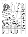
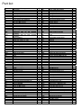
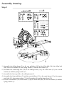
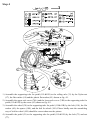
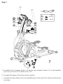
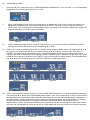
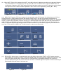
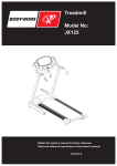
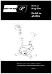
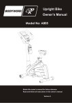
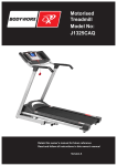
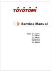
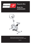
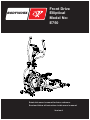
Front Drive
Elliptical
Model No:
E750
BODY WORX
Retain this owner’s manual for future reference
Read and follow all instructions in this owner’s manual
Version A
1
Safety Instructions
• To ensure the best safety of the exerciser, regularly check on
damage and worn parts.
suitable, non-slip mat under the exerciser.
• If you pass on this exerciser to another person or if you allow
another person to use it, make sure that that person is familiar
with the content and instructions in these instructions.
• The general rush is that exercisers and training devices
are not toys. Therefore, they must only be used by
properly informed or instructed persons.
• Only one person should use the exerciser at any given time.
• Stop your workout immediately in case of dizziness,
nausea, chest pain or any other physical symptoms.
In case of doubt, consult your physician immediately.
• Before the first use, regularly make sure that all screws, bolts
and other joints are properly tightened and firmly seated.
• Before you start your work-out, remove all sharp-edged objects
around the exerciser.
• Children, disabled and handicapped persons should use
the exercise only under supervision and in the presence
of another person who may give support and useful
instructions.
• Only use the exercise for your work-out if it works flawlessly.
• Any broken, worn or defective part must immediately be
replaced and/or the exerciser must no longer be used until it has
been properly maintained and repaired.
• Parents and other supervisory persons should be aware of their
responsibility due to situations that may arise where the
exerciser has not been designed to tolerate children’s natural
playful instincts and interest in experimenting.
• Be sure that your body parts and those of other persons
are never close to any moving parts of the exerciser
during its use.
• When fine-tuning the adjustable parts, make sure they
are adjusted properly and note the marked, maximum
adjusting position, for example of the saddle support,
respectively.
• Do not work out immediately after meals
• If you do allow children to use this exerciser, be sure to take into
consideration to assess their psychological and physiological
development as well as their character. Children should use the
exerciser only under adult supervision and be instructed on the
correct and proper use of the exerciser. The exerciser is not a
toy.
• Make sure there is sufficient free space around the exerciser
when you set it up.
• To avoid possible accidents, do not allow children to approach
the exerciser without supervision, since they may use it in a way
for which it is not intended due to their natural play instinct and
interest in experimenting.
• Please note that an improper and excessive work-out may be
harmful to your health.
• Please note that levers and other adjustment mechanisms are
not projecting into the area of movement during the work-out.
• When setting up the exerciser, please make sure that the
exerciser is standing in stable way and that any possible
unevenness of the floor is leveled out.
• Always wear appropriate clothing and shoes suitable for your
workout on the exerciser. The clothes must be designed in a way
so that they will not get caught in any part of the exerciser during
the workout due to their form (for example, length). Be sure to
wear appropriate shoes suitable for the workout, ensure that
they firmly support their feet and have an anti-slip surface sole.
• Be sure to consult a physician before you start any exercise
program. He/She may give you proper hints and advice with
respect to the individual’s intensity of stress for the workout and
sensible eating habits.
• Be sure to set up the exerciser in a dry, flat surface and always
protect it from humidity if you wish to protect the surface against
pressure points and contamination. It is recommended to put a
Exploded drawing:
55
53
52R
101
13
64
60
40
63
9B
7
6
65
54
63
67
103
15
68
107
23R
111
75
105
71
95
106
86
87
48
34
23L
12R
10
41
8
7
9B
69
72
41
60
40
42
72
32R
107
52L
107
73
21
72
74A
74B
63
84
49
102
84
17 14 41
77 80R 8 7 9B
63 93R 93L
41
8
7
9
6
7
9
43
82
24
26
1
12L
35
51
97
45
16
83
46
70
56
50
37
100
95
47 89 45 86
18
94
44
76
80L
57 88 61
19 9A 7 6 22 4 9B 7 8 3
96
6 7 9C
32L
102 84 31 72 33
11R
66 38
9B 7 6
104R
104L
63
39
79
5R 81 8 7 20 2 5L
107
11L 110
78
27
28
90 62 25
98
29
30
99
60 108 58 109 59
85
91
92
36R 36L
Checking list:
10
12R&L
1
49
X1
64
2
3
X1
67&68
52R&L
X1
19
X1
X1
X1
X2
18
X1
X1
11R&L
X1
78
38
X1
23R&L
X2
74A&B
X2
104R&L
X2
9
9A
X6
111
109
X2
X2
M8*1.25*15L
21
94
93R&L
X1
X2
X1
X1
D22*D8.5*1.5T X12
60
X8
63
X22
X2
7
D15.4*D8.2*2T X22
D16*D8.5*1.2T X10
9B
M8*1.25*20L
X8
8
9C
M8*1.25*55L
X2
14
17
M10*1.5*10T
X2
20
M8*15L
X4
75
40
M8*1.25*20L
X4
73
M6*1*15L
X4
107
41
D24*D10*0.4T
X6
77
M6*1.0*5T
X4
110
108
D11.5*D8*3.5T
X2
X2
81
M8*1.25*60L
X4
X2
M5*15L
M8*1.25*20L
X1
X2
X6
X4
X1
106
X1
101
X1
X2
Part list:
Part No.
1
2
3
4
5L
5R
6
7
8
9
9A
9B
9C
10
11L
11R
12L
12R
13
14
15
16
17
18
19
20
21
22
23L
23R
24
25
26
27
28
29
30
31
32L
32R
33
34
35
36L
36R
37
38
39
40
41
42
43
44
45
46
47
48
49
50
51
52L
52R
Description
Q’ty
Main frame
Front stabilizer
Sliding beam
Oval cap
Left foot cap
Right foot cap
Curved washer D22*D8.5*1.5T
Spring washer D15.4*D8.2*2T
Flat washer D16*D8.5*1.2T
Allen bolt M8*1.25*15L
Allen bolt M8*1.25*95L
Allen bolt M8*1.25*20L
Allen bolt M8*1.25*55L
Handlebar post
Supporting tube for left pedal
Supporting tube for right pedal
Supporting tube for left movable
handlebar
Supporting tube for right movable
handlebar
Bushing D35*11
Flat washer D20*D11*2T
Mushroom cap D1 1/4’’*29L
Idle wheel
Nylon nut M10*1.5*10T
Connecting tube
Rear stabilizer
Domed nut M8*1.25*15L
Pedal
Adjustable round wheel
Upper cover (left)
Upper cover (right)
Anti-loose nut M10*1.25*7T
Motor
C-ring D22.5*D18.5*1.2T
Electric cable 400L
Sensor cable 50L
Upper computer cable
Lower computer cable
Rolling axle
Bracket for left pedal
Bracket for right pedal
Crank
Nylon nut M6*1*6T
Multi-groove belt
Left chain cover
Right chain cover
Flywheel
Wheel
Side cover
Bolt M8*1.25*20
Plastic flat washer D10*D24*0.4T
Axle
Bearing #6004ZZ
Bolt M8*52L
Nylon nut M8*1.25*8T
Flat washer D25*D8.5*2.0T
Plastic flat washer D50*D10*1.0T
Flat washer D13*D6.5*1.0T
Handlebar post cover
Plastic cover of spring
Spring
Left movable handlebar
Right movable handlebar
1
1
2
2
1
1
12
30
18
6
2
16
2
1
1
1
1
53
54
55
56
57
58
59
60
61
62
63
64
65
Part No.
Description
Q’ty
66
67
68
Foam (HDR) D30*3T*500L
Foam (HDR) D30*4T*125L
Mushroom cap D1 1/4”*45L
Spring D3.5*D18*52L
Bolt M6*1.0*15L
C-ring S-15 (1T)
Waved washer D21*D16.2*0.3T
Flat washer D25*D8.5*2.0T
Crank axle
Round magnet
Screw ST4*1.41*15L
Computer
Handle pulse
Handle pulse cable 520L
Axle of wheel
Left computer bracket
Right computer bracket
2
2
2
1
4
4
2
6
1
1
22
1
2
2
2
1
1
1
69
Joint
2
4
2
2
1
2
1
1
4
2
2
2
2
2
1
2
1
1
1
1
2
1
1
2
1
1
1
1
1
2
2
4
10
2
2
1
2
1
1
1
1
1
1
1
1
70
71
72
73
74A
74B
75
76
77
78
79
80L
80R
81
82
83
84
85
86
87
88
89
90
91
92
93L
93R
94
95
96
97
98
99
100
101
102
103
104L
104R
105
106
107
108
109
110
111
112
Fixing plate for idle wheel
C-ring S-16 (1T)
Bushing
Bolt M6*1*15L
Upper axle cover
Lower axle cover
Waved washer D21*D16*0.3T
Belt
Nut M6*1.0*5T
Adaptor
Round chain cover
Enforcing plate of left pedal
Enforcing plate of right pedal
Square neck bolt M8*1.25*60L
Flat washer D26*D21*1.5T
Bolt M8*1.25*25L
Waved washer D26*D19.5*0.3T
Screw ST4.2*1.4*20L
Nut M6*1*6T
Nylon washer D6*D19*1.5T
Nylon nut M6*1.0*6T
Nut M8*1.25*6T
Bolt M5*0.8*10L
Screw ST4*1.41*15L
Flat washer D12*D4.3*1T
Rear axle over (left)
Rear axle cover (right)
Foot cap
Bolt M6*65L
Waved washer D27*D21*0.3T
Fixing bracket for magnet
Screw ST4.2*1.4*15L
Tension cable D1.5*230L
Anti-loosen nut M10x1.5*10T
Chest belt
C-ring D21.5*D17.5*1.2T
Plug
Left cover for universal joint
Right cover for universal joint
Bolt M5*0.8*15L
Bottle holder
Screw M5*0.8*15L
Spacer D11.5*D8*3.5T
Belt for wheel
Bolt M8*1.25*20
Bottle
Bottle holder
1
2
18
4
2
2
2
1
4
1
2
1
1
4
1
1
8
11
2
1
4
1
1
16
16
2
2
2
2
1
1
4
1
1
1
8
2
2
2
2
1
6
4
2
4
1
2
Assembly drawing:
Step 1
( x4)
( x2)
81
9A
7
7
D22*D8.5*1.5T
9B
7
M8*1.25*20L
( x4)
D15.4*D8.2*2T
( x4)
( x2)
( x2)
20
7
8
1
20
7
8
9B
7
6
2 81
81
19
(A)
9A 7 6 19
3
8
7
9B
6
94 18 7
9C
1
1) Assemble the sliding beam (3) to the rear stabilizer (19) by the Allen bolt (9A), the Allen bolt
(9B), the curved washer (6), the spring washer (7) and the flat washer (8).
2) Assemble the connecting tube (18) to the sliding beam (3) by the Allen bolt (9C), the curved
washer (6) and the spring washer (7).
3) Assemble the foot cap (94) to the sliding beam (3).
4) Assemble the front stabilizer (2) and the rear stabilizer (19) to the main frame (1) by the square
neck bolt (81), the spring washer (7), the flat washer (8) and the domed nut (20).
5) Fix the rear stabilizer (19) to the frame (1) by the Allen bolt (9B), the curved washer (6) and the
spring washer (7).
Step 2
( x4)
9
M8*1.25*15L
7
D15.4*D8.2*2T
(A)
( x2)
9
M8*1.25*15L
7
D15.4*D8.2*2T
10
49
(B)
30
8
7
9
29
6
7
9
22
2
1) Assemble the handlebar post cover (49) to the handlebar post (10) shown as fig. A.
2) Connect the upper computer cable (29) and the lower computer cable (30) shown as fig. B.
3) Assemble the handlebar post (10) to the main frame (1) by the curved washer (6), the spring
washer (7), the flat washer (8) and the Allen bolt (9).
Step 3
( x2)
40
M8*1.25*20L
60
75
52R
52L
60 40
10
23L
75
52L
x2
3
Assemble the upper cover (left) (23L), the waved washer (75), the movable handlebar (52L&52R),
the flat washer (60) and the bolt (40) to the axle in turn.
Step 4
17
14
73
41
77
41
38
110
109
110 60 108
21 73 77
4-2
4-1
74A
17
14
41
11L
11L
74B
41
31
x2
x2
63
4
1) Assemble the supporting tube for pedal (11L&11R) to the rolling axle (31) by the Nylon nut
(17), the flat washer (14) and the plastic flat washer (41) shown as fig. 4-1.
2) Assemble the upper axle cover (74A) and the lower axle cover (74B) to the supporting tube for
pedal (11L&11R) by the screw (63) shown as fig. 4-2.
3) Assemble the wheel (38) to the supporting tube for pedal (11L&11R) by the bolt (110), the flat
washer (60), the spacer (108), and the belt for wheel (109). Please kindly note the assembling
way of belt for wheel (109) should be correct shown as the picture.
4) Assemble the pedal (21) to the supporting tube for pedal (11L&11R) by the bolt (73) and nut
(77).
Step 5
M8*1.25*20L
( x2)
( x2)
( x6)
( x2)
12R
12L
32L
5-2
5-1
107
12L
104R
84
63
32L
41
60
40
104L
x2
x2
5
1) Assemble the supporting tube for movable handlebar (12L&12R) to the bracket for pedal
(32L&32R) by the waved washer (84), the flat washer (60) ,the plastic washer (41) and the bolt
(40) shown as fig. 5-1.
2) Assemble the cover for universal joint (104L&104R) to the bracket for pedal (32L&32R) by the
screw (63) and the screw (107).
Step 6
101
64
64
65
29
6
ST4*15L
( x16)
6-2
10
52L
52R
23L
52L
63
23R
x2
6-1
x2
9B
7
6
52L
12L
6-3
63
93R
x2
11L
6
3
93L
1) Connect the upper computer cable (29) and the handle pulse cable (65) to the computer (64).
2) Assemble the computer (64) to the handlebar post (10) by screws that attach to the computer.
3) Assemble the supporting tube for movable handlebar (12L&12R) to the movable handlebar
(52L&52R) by the curved washer (6), the spring washer (7) and the Allen bolt (9B) shown as
fig. 6-1.
4) Assemble the upper cover (23L&23R) to the movable handlebar (52L&52R) by the screw (63)
shown as fig. 6-2.
5) Assemble the rear axle cover (93L&93R) to the supporting tube for pedal (11L/11R) by the
screw (63) shown as fig. 6-3.
Step 7
( x2)
63
67
107
68
10
107
63
ST4*15L
107
M5*15L
111
105
106
7
78
1) Assemble the left computer bracket (68) and the right computer bracket (67) to the handlebar
post (10) by the screw (63) and the screw (107).
2) Assemble the adaptor (78) and turn on the computer.
3)
Assemble the bottle holder (106) to the handlebar post (10) by bolt (105). Insert the bolt into the
bolt holder.
INSTRUCTION MANUAL OF SM7690-71
【BUTTON FUNCTIONS】
UP
To make upward adjustment to each function data or increase training resistance.
DOWN
To make downward adjustment to each function data or decrease training resistance.
MODE
To confirm all setting.
STAR/STOP
To start or stop workout.
RESET
To reset current setting and have the monitor switch to initial training mode for selection.
RECOVERY
To test heart rate recovery status.
BODY FAT
To test body fat %
Press the BODY FAT button in standby mode and modify user data.
【DISPLAY FUNCTIONS】
Count up - No preset target, Time will count up from 00:00 to maximum 99:59 with each
TIME
increment is 1 minute.
Count down - If training with preset Time, Time will count down from preset to 00:00. Each
preset increment or decrement is 1 minute between 01:00 to 99:00.
Displays current training speed. Maximum speed is 99.9 KM/H or ML/H.
SPEED
Displays the Rotation Per Minute. Display range 0~15~999
RPM
Accumulates total distance from 00:00 up to 99.99 KM or ML. The user may preset target
distance data by pressing UP/DOWN button. Each incensement is 0.1KM or ML.
Accumulates calories consumption during training from 0 to maximum 9999 calories.
(This data is a rough guide for comparison of different exercise sessions which can not be
used in medical treatment.)
User may set up target pulse from 0 - 30 to 230 and computer buzzer will beep when actual
heart rate is over the target value during workout.
Display current workout watts. Display range 0~999.
DISTANCE
CALORIES
PULSE
WATTS
【OPERATING PROCEDURE】
(1)
Plug in power supply cord (or press the RESET key for 2 seconds); LCD will have full display with all segments for
2 seconds with a beep. (Figure 1) Wheel diameter value will show in the SPEED column. "E" for EU regulation or
"A" for Asian regulation will show in the TIME column. KM (K)/ ML (M) will show in the DISTANCE column for 1
second (Figure 2) and then enter to the SETTING mode. Motor will always go back to zero first and then turn into
LOAD=1 and in wait for all settings.
Figure)
(2)
Figure 2
The console will enter to the USER setting after determined. (With BODYFAT function) Choose one group within
U1~U4 to enter personal data. Enter SEX (Figure 6), AGE (Figure 7), HEIGHT (Figure 8), WEIGHT (Figure 8) and
then enter into the workout mode after determined (Figure 9).
Figure 5
Figure 6
Figure 8
Figure 9
Figure 7
(3)
In the setting mode (Figure 10), press ▲ or ▼ key to adjust M (Manual), P (Program), ♥ (HRC), W (Watt), and U
(User) sequentially in circulation order.
Figure 10
(4)
Press ▲ or ▼ key allows user to have MANUAL (Figure 10) → PROGRAM (Figure 11) → HRC (Figure 12) →
WATT (Figure 13) → User Program (Figure 14) → MANUAL in cycle order. Press the MODE key to enter into the
MODE function display.
Figure 11
Figure 13
(5)
i.
Figure 12
Figure 14
MANUAL function setting:
Press ▲ or ▼ key to adjust LEVEL value (Figure 15). The console will have flashing text showing on the screen
and ready for the adjustment to be determined. Default value will be LEVEL1.
Figure 15
ii.
Press ▲ or ▼ key to adjust level value to increase or decrease 1 digit each press; press and hold the key to have
+/-2 binary digits each second. Stop when adjustment suspended. LEVEL adjustment doesn't have circulation
function.
iii.
In the START mode, LEVEL value is adjustable under the MANUAL mode and the text and value of LEVEL will
be displayed. WATT value will be shown on the screen after 3 seconds without pressing ▲ or ▼ key.
iv.
iv.
Press ▲ or ▼ key to adjust values for TIME (Figure 16), DISTANCE (Figure 17), CALORIES (Figure 18), and
PULSE (Figure 19) in a circulation order (feature values will be shown on the console screen).
Press the START key to have the implementation of the program (Figure 20). The values show on RPM BAR and
PULSE BAR will be adjusted according to changes in the process of movement. Press the STOP key to pause
exercising and all values will be retained on the screen (PULSE signal will not be affected). Press the RESET key
to return to PROGRAM SELECT.
Figure 16
Figure 19
Figure 17
Figure 20
Figure 18
(6)
PROGRAM SETTING:
i.
Press ▲ or ▼ key to select one of the 12 PROGRAMS like PROGRAM P01, P02, P03, P04... P12. Corresponding
graphics will show flashing texts (Figure 21) on LCD.
Figure 21
ii.
When a PROGRAM is chosen, the value will be shown in flashing text in the LEVEL column and ready for the
adjustment to be determined. Default value will be set as LEVEL1. Press ▲ or ▼ key to adjust the value in
LEVEL mode. The console will show instant display graphic according to the changes of adjustments. (Figure 22)
Press the MODE key for LEVEL value confirmation.
Figure 22
iii.
(7)
Figure 23
LEVEL value is adjustable under the START mode and the text and value of LEVEL will be displayed. WATT
value will be restored after 3 seconds without pressing ▲ or ▼ key.
When H.R.C. mode is selected (Figure 30), LCD display will show age as default value of 25 (adjust with ▲ or ▼
key) (Figure 25). Press the MODE key for confirmation and press ▲ or ▼ key to choose 55%, 75%, 90% or
TARGET. (Figure 26~29) The default value that’s calculated according to user age input will be shown in the
PULSE column with 1HZ flashing text For example: When a TARGET mode is selected; LCD will show value of100
in flashing text. Press ▲ or ▼ button to set TARGET value (30~230) with circulation function. Press the MODE key
and ▲ or ▼ key to set TIME (Figure 30). Press the START key to start the program.
Figure 24
Figure 25
Figure 27
Figure 28
Figure 26
Figure 29
Figure 30
(8)
When User Program is selected (Figure 31), chosen USER PROGRAM data (U1~U4) will be loaded automatically.
User can press ▲ or ▼ key to set a PROGRAM pattern (that is, each axis corresponds to a LEVEL value) that has
flashing display texts and the light will be fixed after determined. The text and value will be ready for adjustment in
the LOAD column. LEVEL value will be shown in flashing text. Press the MODE key for confirmation. A complete
timeline has 8 PROGRAM patterns in total to be set and the PROGRAM will be in accordance with the
implementation. (Figure 33) Press the MODE key for 2 seconds to stop the process and the timeline will be set as
the value from last adjustment. Press ▲ or ▼ key for TIME setting and press the START key to start the program.
Figure 31
Figure 32
Figure 33
(9)
When WATT (Figure 34) is selected, the WATT value will be shown in flashing text waiting to be adjusted. Default =
120 will be shown on LCD (Figure 35) User can press ▲ or ▼ to set WATT value. Press the MODE button for
confirmation. Press ▲ or ▼ for TIME setting (Figure 36) and start workout by the WATT value and exercise status
user inputs for LEVEL value automatic adjustment. WATT value can be adjusted by pressing ▲ or ▼ key.
Figure 34
Figure 35
Figure 36
(10) BODY FAT: Press the FAT key to measure fat is executable under STOP mode. UX will be shown on LCD for 2
seconds (Figure 37) before entering into the test screen (Figure 38~39). Test will be processed after detecting a
heartbeat from the handgrips (Figure 40). FAT% (Figure 41), BMI (Figure 42) and weight symbols (Figure 43 ~ 46) will be
shown on screen after 8 seconds. Press the FAT key for 2 seconds under STOP mode will enter into personal data for
AGE, HEIGHT, and WEIGHT setting. Press the MODE key for confirmation after determined to start the program. If
there's no heartbeat signal during testing process, the input will show E-1 on the screen. (Figure 47) If the test value is
out of the FAT% range 5~50 (BMI 5~0), E-4 will be shown on the screen (Figure 48).
(11)
Figure 37
Figure 38
Figure 40
Figure 41
Figure 43
Figure 44
Figure 46
Figure 47
Figure 39
Figure 42
Figure 45
Figure 48
RECOVERY: When there's a heartbeat signal input and display value under START or STOP mode, press the
RECOVERY key to execute function. LCD will only display TIME, PULSE (Figure 49), TIME will countdown to 0:00
and the FX value will be shown on the screen (F1~F6) (Figure 50). Press the RECOVERY key to return to
previous display during the test or when the test is accrued. A heartbeat signal is required to continue detecting to
demonstrate the actual value of the heart rate.
Figure 49
Figure 50
BODYWORX
BODY WORX