1
Cisco Aironet 1100 Series Access Point
Hardware Installation Guide
October 2003
Corporate Headquarters
Cisco Systems, Inc.
170 West Tasman Drive
San Jose, CA 95134-1706
USA
http://www.cisco.com
Tel: 408 526-4000
800 553-NETS (6387)
Fax: 408 526-4100
Text Part Number: OL-4309-02
THE SPECIFICATIONS AND INFORMATION REGARDING THE PRODUCTS IN THIS MANUAL ARE SUBJECT TO CHANGE WITHOUT NOTICE. ALL
STATEMENTS, INFORMATION, AND RECOMMENDATIONS IN THIS MANUAL ARE BELIEVED TO BE ACCURATE BUT ARE PRESENTED WITHOUT
WARRANTY OF ANY KIND, EXPRESS OR IMPLIED. USERS MUST TAKE FULL RESPONSIBILITY FOR THEIR APPLICATION OF ANY PRODUCTS.
THE SOFTWARE LICENSE AND LIMITED WARRANTY FOR THE ACCOMPANYING PRODUCT ARE SET FORTH IN THE INFORMATION PACKET THAT
SHIPPED WITH THE PRODUCT AND ARE INCORPORATED HEREIN BY THIS REFERENCE. IF YOU ARE UNABLE TO LOCATE THE SOFTWARE LICENSE
OR LIMITED WARRANTY, CONTACT YOUR CISCO REPRESENTATIVE FOR A COPY.
The following information is for FCC compliance of Class A devices: This equipment has been tested and found to comply with the limits for a Class A digital device, pursuant
to part 15 of the FCC rules. These limits are designed to provide reasonable protection against harmful interference when the equipment is operated in a commercial
environment. This equipment generates, uses, and can radiate radio-frequency energy and, if not installed and used in accordance with the instruction manual, may cause
harmful interference to radio communications. Operation of this equipment in a residential area is likely to cause harmful interference, in which case users will be required
to correct the interference at their own expense.
The following information is for FCC compliance of Class B devices: The equipment described in this manual generates and may radiate radio-frequency energy. If it is not
installed in accordance with Cisco’s installation instructions, it may cause interference with radio and television reception. This equipment has been tested and found to
comply with the limits for a Class B digital device in accordance with the specifications in part 15 of the FCC rules. These specifications are designed to provide reasonable
protection against such interference in a residential installation. However, there is no guarantee that interference will not occur in a particular installation.
Modifying the equipment without Cisco’s written authorization may result in the equipment no longer complying with FCC requirements for Class A or Class B digital
devices. In that event, your right to use the equipment may be limited by FCC regulations, and you may be required to correct any interference to radio or television
communications at your own expense.
You can determine whether your equipment is causing interference by turning it off. If the interference stops, it was probably caused by the Cisco equipment or one of its
peripheral devices. If the equipment causes interference to radio or television reception, try to correct the interference by using one or more of the following measures:
• Turn the television or radio antenna until the interference stops.
• Move the equipment to one side or the other of the television or radio.
• Move the equipment farther away from the television or radio.
• Plug the equipment into an outlet that is on a different circuit from the television or radio. (That is, make certain the equipment and the television or radio are on circuits
controlled by different circuit breakers or fuses.)
Modifications to this product not authorized by Cisco Systems, Inc. could void the FCC approval and negate your authority to operate the product.
The Cisco implementation of TCP header compression is an adaptation of a program developed by the University of California, Berkeley (UCB) as part of UCB’s public
domain version of the UNIX operating system. All rights reserved. Copyright © 1981, Regents of the University of California.
NOTWITHSTANDING ANY OTHER WARRANTY HEREIN, ALL DOCUMENT FILES AND SOFTWARE OF THESE SUPPLIERS ARE PROVIDED “AS IS” WITH
ALL FAULTS. CISCO AND THE ABOVE-NAMED SUPPLIERS DISCLAIM ALL WARRANTIES, EXPRESSED OR IMPLIED, INCLUDING, WITHOUT
LIMITATION, THOSE OF MERCHANTABILITY, FITNESS FOR A PARTICULAR PURPOSE AND NONINFRINGEMENT OR ARISING FROM A COURSE OF
DEALING, USAGE, OR TRADE PRACTICE.
IN NO EVENT SHALL CISCO OR ITS SUPPLIERS BE LIABLE FOR ANY INDIRECT, SPECIAL, CONSEQUENTIAL, OR INCIDENTAL DAMAGES, INCLUDING,
WITHOUT LIMITATION, LOST PROFITS OR LOSS OR DAMAGE TO DATA ARISING OUT OF THE USE OR INABILITY TO USE THIS MANUAL, EVEN IF CISCO
OR ITS SUPPLIERS HAVE BEEN ADVISED OF THE POSSIBILITY OF SUCH DAMAGES.
CCIP, CCSP, the Cisco Arrow logo, the Cisco Powered Network mark, Cisco Unity, Follow Me Browsing, FormShare, and StackWise are trademarks of Cisco Systems, Inc.;
Changing the Way We Work, Live, Play, and Learn, and iQuick Study are service marks of Cisco Systems, Inc.; and Aironet, ASIST, BPX, Catalyst, CCDA, CCDP, CCIE, CCNA,
CCNP, Cisco, the Cisco Certified Internetwork Expert logo, Cisco IOS, the Cisco IOS logo, Cisco Press, Cisco Systems, Cisco Systems Capital, the Cisco Systems logo,
Empowering the Internet Generation, Enterprise/Solver, EtherChannel, EtherSwitch, Fast Step, GigaStack, Internet Quotient, IOS, IP/TV, iQ Expertise, the iQ logo, iQ Net
Readiness Scorecard, LightStream, MGX, MICA, the Networkers logo, Networking Academy, Network Registrar, Packet, PIX, Post-Routing, Pre-Routing, RateMUX, Registrar,
ScriptShare, SlideCast, SMARTnet, StrataView Plus, Stratm, SwitchProbe, TeleRouter, The Fastest Way to Increase Your Internet Quotient, TransPath, and VCO are registered
trademarks of Cisco Systems, Inc. and/or its affiliates in the U.S. and certain other countries.
All other trademarks mentioned in this document or Web site are the property of their respective owners. The use of the word partner does not imply a partnership relationship
between Cisco and any other company. (0304R)
Cisco Aironet 1100 Series Access Point Hardware Installation Guide
Copyright © 2003 Cisco Systems, Inc. All rights reserved.
C ON T E N T S
Audience
Purpose
ix
ix
Organization
ix
Conventions
x
Related Publications
xii
Obtaining Documentation xii
Cisco.com xii
Documentation CD-ROM xiii
Ordering Documentation xiii
Documentation Feedback xiii
Obtaining Technical Assistance xiii
Cisco TAC Website xiv
Opening a TAC Case xiv
TAC Case Priority Definitions xiv
Obtaining Additional Publications and Information
CHAPTER
1
Overview
xv
1-1
Hardware Features 1-2
Single Radio Operation 1-2
Ethernet Port 1-2
LEDs 1-3
Power Sources 1-3
UL 2043 Certification 1-4
Anti-Theft Features 1-4
Network Configuration Examples 1-5
Root Unit on a Wired LAN 1-5
Repeater Unit that Extends Wireless Range 1-6
Central Unit in an All-Wireless Network 1-7
Cisco Aironet 1100 Series Access Point Hardware Installation Guide
OL-4309-02
iii
Contents
CHAPTER
2
Installing the Access Point
2-1
Safety Information 2-2
FCC Safety Compliance Statement
General Safety Guidelines 2-2
Warnings
2-2
2-2
Unpacking the Access Point 2-3
Package Contents 2-3
Basic Installation Guidelines
2-3
Before Beginning the Installation
Installation Summary
2-4
2-4
Connecting the Ethernet and Power Cables 2-5
Connecting to an Ethernet Network with an Inline Power Source
Connecting to an Ethernet Network with Local Power 2-6
Powering Up the Access Point 2-7
CHAPTER
3
Configuring the Access Point for the First Time
3-1
Before You Start 3-2
Resetting the Access Point to Default Settings
Obtaining and Assigning an IP Address
3-3
Connecting to the Access Point Locally
3-3
Assigning Basic Settings 3-4
Default Settings on the Express Setup Page
Protecting Your Wireless LAN
3-2
3-7
3-8
Using the IP Setup Utility 3-8
Obtaining and Installing IPSU 3-8
Using IPSU to Find the Access Point’s IP Address 3-9
Using IPSU to Set the Access Point’s IP Address and SSID
Assigning an IP Address Using the CLI
4
Using the Web-Browser Interface
3-11
4-1
Using the Web-Browser Interface for the First Time
4-2
Using the Management Pages in the Web-Browser Interface
Using Action Buttons 4-3
Character Restrictions in Entry Fields 4-5
Using Online Help
3-10
3-11
Using a Telnet Session to Access the CLI
CHAPTER
2-6
4-2
4-5
Cisco Aironet 1100 Series Access Point Hardware Installation Guide
iv
OL-4309-02
Contents
CHAPTER
5
Using the Command-Line Interface
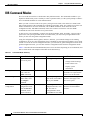
IOS Command Modes
Getting Help
5-1
5-2
5-3
Abbreviating Commands
5-3
Using no and default Forms of Commands
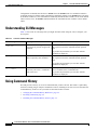
Understanding CLI Messages
5-3
5-4
Using Command History 5-4
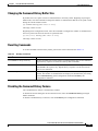
Changing the Command History Buffer Size 5-5
Recalling Commands 5-5
Disabling the Command History Feature 5-5
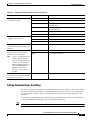
Using Editing Features 5-6
Enabling and Disabling Editing Features 5-6
Editing Commands through Keystrokes 5-6
Editing Command Lines that Wrap 5-7
Searching and Filtering Output of show and more Commands
Accessing the CLI 5-9
Opening the CLI with Telnet 5-9
Opening the CLI with Secure Shell
CHAPTER
6
Mounting Instructions
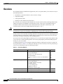
Overview
5-9
6-1
6-2
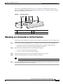
Mounting on a Horizontal or Vertical Surface
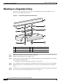
Mounting on a Suspended Ceiling
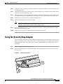
Using the Security Hasp Adapter
2.4-GHz Radio Upgrade
Upgrade Overview
Unpacking the Radio
6-8
6-9
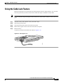
Using the Cable Lock Feature
7
6-6
6-7
Mounting on a Cubical Wall Partition
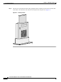
Using the Desktop Holster
6-3
6-4
Mounting Above a Suspended Ceiling
CHAPTER
5-8
6-11
7-1
7-2
7-2
Removing the Back Cover
7-3
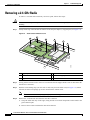
Removing a 2.4-GHz Radio
7-4
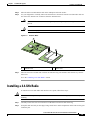
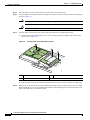
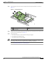
Installing a 2.4-GHz Radio
7-5
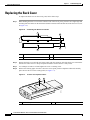
Replacing the Back Cover
7-8
Cisco Aironet 1100 Series Access Point Hardware Installation Guide
OL-4309-02
v
Contents
Finding the Software Version
CHAPTER
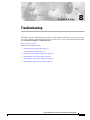
Troubleshooting
8
7-9
8-1
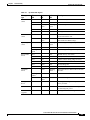
Checking the Top Panel LEDs
8-2
Checking Basic Settings 8-4
SSID 8-4
WEP Keys 8-4
Security Settings 8-4
Resetting to the Default Configuration
Using the MODE Button 8-5
Using the Web Browser Interface
8-4
8-5
Reloading the Access Point Image 8-6
Using the MODE button 8-6
Web Browser Interface 8-7
Browser HTTP Interface 8-7
Browser TFTP Interface 8-7
Obtaining the Access Point Image File
Obtaining the TFTP Server Software
APPENDIX
A
Translated Safety Warnings
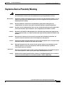
Explosive Device Proximity Warning
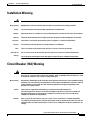
Installation Warning
B
A-2
A-3
A-4
A-5
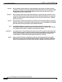
Circuit Breaker (15A) Warning
APPENDIX
8-8
A-1
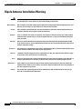
Dipole Antenna Installation Warning
Lightning Activity Warning
8-8
A-5
Declarations of Conformity and Regulatory Information
B-1
Manufacturers Federal Communication Commission Declaration of Conformity Statement
B-2
Department of Communications—Canada B-3
Canadian Compliance Statement B-3
European Community, Switzerland, Norway, Iceland, and Liechtenstein B-3
Declaration of Conformity with Regard to the R&TTE Directive 1999/5/EC
Declaration of Conformity for RF Exposure
B-3
B-5
Guidelines for Operating Cisco Aironet Access Points and Bridges in Japan
Japanese Translation B-5
English Translation B-5
B-5
Cisco Aironet 1100 Series Access Point Hardware Installation Guide
vi
OL-4309-02
Contents
Administrative Rules for Cisco Aironet Access Points in Taiwan
All Access Points B-6
Chinese Translation B-6
English Translation B-6
APPENDIX
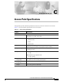
C
Access Point Specifications
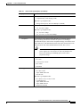
APPENDIX
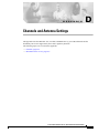
D
Channels and Antenna Settings
B-6
C-1
D-1
Channels D-2
IEEE 802.11b (2.4-GHz Band)
IEEE 802.11g (2.4-GHz Band)
D-2
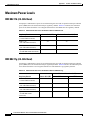
Maximum Power Levels D-4
IEEE 802.11b (2.4-GHz Band)
IEEE 802.11g (2.4-GHz Band)
D-4
D-3
D-4
GLOSSARY
INDEX
Cisco Aironet 1100 Series Access Point Hardware Installation Guide
OL-4309-02
vii
Contents
Cisco Aironet 1100 Series Access Point Hardware Installation Guide
viii
OL-4309-02
Preface
Audience
This guide is for the networking professional who installs and manages the Cisco Aironet 1100 Series
Access Point, hereafter referred to as the access point. To use this guide, you should have experience
working with the Cisco IOS software and be familiar with the concepts and terminology of wireless local
area networks.
Purpose
This guide provides the information you need to install and initially configure your access point,
including procedures for using the IOS commands that have been created or changed for use with the
access point. It does not provide detailed information about these commands. For detailed information
about these commands, refer to the Cisco IOS Command Reference for Cisco Aironet Access Points and
Bridges for this release. For information about the standard IOS Release 12.2 commands, refer to the
IOS documentation set available from the Cisco.com home page at Service and Support > Technical
Documents. On the Cisco Product Documentation home page, select Release 12.2 from the Cisco IOS
Software drop-down menu.
This guide also includes an overview of the access point web-based interface (APWI), which contains
all the functionality of the command-line interface (CLI). This guide does not provide field-level
descriptions of the APWI windows nor does it provide the procedures for configuring the access point
from the APWI. For all APWI window descriptions and procedures, refer to the access point online help,
which is available from the Help buttons on the APWI pages.
Organization
This guide is organized into these chapters:
Chapter 1, “Overview,” lists the software and hardware features of the access point and describes the
access point’s role in your network.
Chapter 2, “Installing the Access Point,” describes how to connect Ethernet and power cables and
provides an installation summary, safety warnings, and general guidelines.
Chapter 3, “Configuring the Access Point for the First Time,” describes how to configure basic settings
on a new access point.
Cisco Aironet 1100 Series Access Point Hardware Installation Guide
OL-4309-02
ix
Preface
Conventions
Chapter 4, “Using the Web-Browser Interface,” describes how to use the web-browser interface to
configure the access point.
Chapter 5, “Using the Command-Line Interface,” describes how to use the command-line interface
(CLI) to configure the access point.
Chapter 6, “Mounting Instructions,” describes how to mount the access point on a desktop, wall, or
ceiling.
Chapter 7, “2.4-GHz Radio Upgrade,” provides upgrade instructions for changing the 2.4 GHz radio.
Chapter 8, “Troubleshooting,” provides troubleshooting procedures for basic problems with the access
point.
Appendix A, “Translated Safety Warnings,” provides translations of the safety warnings that appear in
this publication.
Appendix B, “Declarations of Conformity and Regulatory Information,” provides declarations of
conformity and regulatory information for the access point.
Appendix C, “Access Point Specifications,” lists technical specifications for the access point.
Appendix D, “Channels and Antenna Settings,” lists the access point radio channels and the maximum
power levels supported by the world’s regulatory domains.
Conventions
This publication uses these conventions to convey instructions and information:
Command descriptions use these conventions:
•
Commands and keywords are in boldface text.
•
Arguments for which you supply values are in italic.
•
Square brackets ([ ]) mean optional elements.
•
Braces ({ }) group required choices, and vertical bars ( | ) separate the alternative elements.
•
Braces and vertical bars within square brackets ([{ | }]) mean a required choice within an optional
element.
Interactive examples use these conventions:
•
Terminal sessions and system displays are in screen font.
•
Information you enter is in boldface screen font.
•
Nonprinting characters, such as passwords or tabs, are in angle brackets (< >).
Notes, cautions, and timesavers use these conventions and symbols:
Tip
Means the following will help you solve a problem. The tips information might not be troubleshooting
or even an action, but could be useful information.
Note
Means reader take note. Notes contain helpful suggestions or references to materials not contained in
this manual.
Cisco Aironet 1100 Series Access Point Hardware Installation Guide
x
OL-4309-02
Preface
Conventions
Caution
Warning
Waarschuwing
Means reader be careful. In this situation, you might do something that could result equipment damage
or loss of data.
This warning symbol means danger. You are in a situation that could cause bodily injury. Before you
work on any equipment, be aware of the hazards involved with electrical circuitry and be familiar
with standard practices for preventing accidents. (To see translations of the warnings that appear
in this publication, refer to the appendix “Translated Safety Warnings.”)
Dit waarschuwingssymbool betekent gevaar. U verkeert in een situatie die lichamelijk letsel kan
veroorzaken. Voordat u aan enige apparatuur gaat werken, dient u zich bewust te zijn van de bij
elektrische schakelingen betrokken risico’s en dient u op de hoogte te zijn van standaard
maatregelen om ongelukken te voorkomen. (Voor vertalingen van de waarschuwingen die in deze
publicatie verschijnen, kunt u het aanhangsel “Translated Safety Warnings” (Vertalingen van
veiligheidsvoorschriften) raadplegen.)
Varoitus
Tämä varoitusmerkki merkitsee vaaraa. Olet tilanteessa, joka voi johtaa ruumiinvammaan. Ennen
kuin työskentelet minkään laitteiston parissa, ota selvää sähkökytkentöihin liittyvistä vaaroista ja
tavanomaisista onnettomuuksien ehkäisykeinoista. (Tässä julkaisussa esiintyvien varoitusten
käännökset löydät liitteestä "Translated Safety Warnings" (käännetyt turvallisuutta koskevat
varoitukset).)
Attention
Ce symbole d’avertissement indique un danger. Vous vous trouvez dans une situation pouvant
entraîner des blessures. Avant d’accéder à cet équipement, soyez conscient des dangers posés par
les circuits électriques et familiarisez-vous avec les procédures courantes de prévention des
accidents. Pour obtenir les traductions des mises en garde figurant dans cette publication, veuillez
consulter l’annexe intitulée « Translated Safety Warnings » (Traduction des avis de sécurité).
Warnung
Dieses Warnsymbol bedeutet Gefahr. Sie befinden sich in einer Situation, die zu einer
Körperverletzung führen könnte. Bevor Sie mit der Arbeit an irgendeinem Gerät beginnen, seien Sie
sich der mit elektrischen Stromkreisen verbundenen Gefahren und der Standardpraktiken zur
Vermeidung von Unfällen bewußt. (Übersetzungen der in dieser Veröffentlichung enthaltenen
Warnhinweise finden Sie im Anhang mit dem Titel “Translated Safety Warnings” (Übersetzung der
Warnhinweise).)
Avvertenza
Questo simbolo di avvertenza indica un pericolo. Si è in una situazione che può causare infortuni.
Prima di lavorare su qualsiasi apparecchiatura, occorre conoscere i pericoli relativi ai circuiti
elettrici ed essere al corrente delle pratiche standard per la prevenzione di incidenti. La traduzione
delle avvertenze riportate in questa pubblicazione si trova nell’appendice, “Translated Safety
Warnings” (Traduzione delle avvertenze di sicurezza).
Advarsel
Dette varselsymbolet betyr fare. Du befinner deg i en situasjon som kan føre til personskade. Før du
utfører arbeid på utstyr, må du være oppmerksom på de faremomentene som elektriske kretser
innebærer, samt gjøre deg kjent med vanlig praksis når det gjelder å unngå ulykker. (Hvis du vil se
oversettelser av de advarslene som finnes i denne publikasjonen, kan du se i vedlegget "Translated
Safety Warnings" [Oversatte sikkerhetsadvarsler].)
Cisco Aironet 1100 Series Access Point Hardware Installation Guide
OL-4309-02
xi
Preface
Related Publications
Aviso
Este símbolo de aviso indica perigo. Encontra-se numa situação que lhe poderá causar danos
fisicos. Antes de começar a trabalhar com qualquer equipamento, familiarize-se com os perigos
relacionados com circuitos eléctricos, e com quaisquer práticas comuns que possam prevenir
possíveis acidentes. (Para ver as traduções dos avisos que constam desta publicação, consulte o
apêndice “Translated Safety Warnings” - “Traduções dos Avisos de Segurança”).
¡Advertencia!
Este símbolo de aviso significa peligro. Existe riesgo para su integridad física. Antes de manipular
cualquier equipo, considerar los riesgos que entraña la corriente eléctrica y familiarizarse con los
procedimientos estándar de prevención de accidentes. (Para ver traducciones de las advertencias
que aparecen en esta publicación, consultar el apéndice titulado “Translated Safety Warnings.”)
Varning!
Denna varningssymbol signalerar fara. Du befinner dig i en situation som kan leda till personskada.
Innan du utför arbete på någon utrustning måste du vara medveten om farorna med elkretsar och
känna till vanligt förfarande för att förebygga skador. (Se förklaringar av de varningar som
förekommer i denna publikation i appendix "Translated Safety Warnings" [Översatta
säkerhetsvarningar].)
Related Publications
These documents provide complete information about the access point:
•
Cisco IOS Software Configuration Guide for Access Points
•
Release Notes for 1100 Series Access Points
•
Cisco IOS Command Reference for Access Points and Bridges
Click this link to browse to the Cisco Aironet documentation home page:
http://www.cisco.com/univercd/cc/td/doc/product/wireless/index.htm
To browse to the 1100 series access point documentation, select Aironet 1100 Series Wireless LAN
Products > Cisco Aironet 1100 Series Access Points.
Obtaining Documentation
Cisco provides several ways to obtain documentation, technical assistance, and other technical
resources. These sections explain how to obtain technical information from Cisco Systems.
Cisco.com
You can access the most current Cisco documentation on the World Wide Web at this URL:
http://www.cisco.com/univercd/home/home.htm
You can access the Cisco website at this URL:
http://www.cisco.com
International Cisco websites can be accessed from this URL:
http://www.cisco.com/public/countries_languages.shtml
Cisco Aironet 1100 Series Access Point Hardware Installation Guide
xii
OL-4309-02
Preface
Obtaining Technical Assistance
Documentation CD-ROM
Cisco documentation and additional literature are available in a Cisco Documentation CD-ROM
package, which may have shipped with your product. The Documentation CD-ROM is updated regularly
and may be more current than printed documentation. The CD-ROM package is available as a single unit
or through an annual or quarterly subscription.
Registered Cisco.com users can order a single Documentation CD-ROM (product number
DOC-CONDOCCD=) through the Cisco Ordering tool:
http://www.cisco.com/en/US/partner/ordering/ordering_place_order_ordering_tool_launch.html
All users can order annual or quarterly subscriptions through the online Subscription Store:
http://www.cisco.com/go/subscription
Ordering Documentation
You can find instructions for ordering documentation at this URL:
http://www.cisco.com/univercd/cc/td/doc/es_inpck/pdi.htm
You can order Cisco documentation in these ways:
•
Registered Cisco.com users (Cisco direct customers) can order Cisco product documentation from
the Networking Products MarketPlace:
http://www.cisco.com/en/US/partner/ordering/index.shtml
•
Nonregistered Cisco.com users can order documentation through a local account representative by
calling Cisco Systems Corporate Headquarters (California, USA.) at 408 526-7208 or, elsewhere in
North America, by calling 800 553-NETS (6387).
Documentation Feedback
You can submit comments electronically on Cisco.com. On the Cisco Documentation home page, click
Feedback at the top of the page.
You can send your comments in e-mail to [email protected].
You can submit comments by using the response card (if present) behind the front cover of your
document or by writing to the following address:
Cisco Systems
Attn: Customer Document Ordering
170 West Tasman Drive
San Jose, CA 95134-9883
We appreciate your comments.
Obtaining Technical Assistance
For all customers, partners, resellers, and distributors who hold valid Cisco service contracts, the Cisco
Technical Assistance Center (TAC) provides 24-hour, award-winning technical support services, online
and over the phone. Cisco.com features the Cisco TAC website as an online starting point for technical
assistance.
Cisco Aironet 1100 Series Access Point Hardware Installation Guide
OL-4309-02
xiii
Preface
Obtaining Technical Assistance
Cisco TAC Website
The Cisco TAC website (http://www.cisco.com/tac) provides online documents and tools for
troubleshooting and resolving technical issues with Cisco products and technologies. The Cisco TAC
website is available 24 hours a day, 365 days a year.
Accessing all the tools on the Cisco TAC website requires a Cisco.com user ID and password. If you
have a valid service contract but do not have a login ID or password, register at this URL:
http://tools.cisco.com/RPF/register/register.do
Opening a TAC Case
The online TAC Case Open Tool (http://www.cisco.com/tac/caseopen) is the fastest way to open P3 and
P4 cases. (Your network is minimally impaired or you require product information). After you describe
your situation, the TAC Case Open Tool automatically recommends resources for an immediate solution.
If your issue is not resolved using these recommendations, your case will be assigned to a Cisco TAC
engineer.
For P1 or P2 cases (your production network is down or severely degraded) or if you do not have Internet
access, contact Cisco TAC by telephone. Cisco TAC engineers are assigned immediately to P1 and P2
cases to help keep your business operations running smoothly.
To open a case by telephone, use one of the following numbers:
Asia-Pacific: +61 2 8446 7411 (Australia: 1 800 805 227)
EMEA: +32 2 704 55 55
USA: 1 800 553-2447
For a complete listing of Cisco TAC contacts, go to this URL:
http://www.cisco.com/warp/public/687/Directory/DirTAC.shtml
TAC Case Priority Definitions
To ensure that all cases are reported in a standard format, Cisco has established case priority definitions.
Priority 1 (P1)—Your network is “down” or there is a critical impact to your business operations. You
and Cisco will commit all necessary resources around the clock to resolve the situation.
Priority 2 (P2)—Operation of an existing network is severely degraded, or significant aspects of your
business operation are negatively affected by inadequate performance of Cisco products. You and Cisco
will commit full-time resources during normal business hours to resolve the situation.
Priority 3 (P3)—Operational performance of your network is impaired, but most business operations
remain functional. You and Cisco will commit resources during normal business hours to restore service
to satisfactory levels.
Priority 4 (P4)—You require information or assistance with Cisco product capabilities, installation, or
configuration. There is little or no effect on your business operations.
Cisco Aironet 1100 Series Access Point Hardware Installation Guide
xiv
OL-4309-02
Preface
Obtaining Additional Publications and Information
Obtaining Additional Publications and Information
Information about Cisco products, technologies, and network solutions is available from various online
and printed sources.
•
The Cisco Product Catalog describes the networking products offered by Cisco Systems, as well as
ordering and customer support services. Access the Cisco Product Catalog at this URL:
http://www.cisco.com/en/US/products/products_catalog_links_launch.html
•
Cisco Press publishes a wide range of networking publications. Cisco suggests these titles for new
and experienced users: Internetworking Terms and Acronyms Dictionary, Internetworking
Technology Handbook, Internetworking Troubleshooting Guide, and the Internetworking Design
Guide. For current Cisco Press titles and other information, go to Cisco Press online at this URL:
http://www.ciscopress.com
•
Packet magazine is the Cisco quarterly publication that provides the latest networking trends,
technology breakthroughs, and Cisco products and solutions to help industry professionals get the
most from their networking investment. Included are networking deployment and troubleshooting
tips, configuration examples, customer case studies, tutorials and training, certification information,
and links to numerous in-depth online resources. You can access Packet magazine at this URL:
http://www.cisco.com/go/packet
•
iQ Magazine is the Cisco bimonthly publication that delivers the latest information about Internet
business strategies for executives. You can access iQ Magazine at this URL:
http://www.cisco.com/go/iqmagazine
•
Internet Protocol Journal is a quarterly journal published by Cisco Systems for engineering
professionals involved in designing, developing, and operating public and private internets and
intranets. You can access the Internet Protocol Journal at this URL:
http://www.cisco.com/en/US/about/ac123/ac147/about_cisco_the_internet_protocol_journal.html
•
Training—Cisco offers world-class networking training. Current offerings in network training are
listed at this URL:
http://www.cisco.com/en/US/learning/index.html
Cisco Aironet 1100 Series Access Point Hardware Installation Guide
OL-4309-02
xv
Preface
Obtaining Additional Publications and Information
Cisco Aironet 1100 Series Access Point Hardware Installation Guide
xvi
OL-4309-02
C H A P T E R
1
Overview
Cisco Aironet 1100 Series Access Point provides a secure, affordable, and easy-to-use wireless LAN
solution that combines mobility and flexibility with the enterprise-class features required by networking
professionals. With a management system based on Cisco IOS software, the 1100 series is a Wi-Fi
certified, wireless LAN transceiver. The 1100 series access point uses a single mini-PCI radio
(IEEE 802.11b-compliant or IEEE 802.11g-compliant) that can be upgraded to future radio
technologies.
The access point serves as the connection point between wireless and wired networks or as the center
point of a stand-alone wireless network. In large installations, wireless users within radio range of an
access point can roam throughout a facility while maintaining seamless, uninterrupted access to the
network.
You can configure and monitor the access point using the command-line interface (CLI), the
browser-based management system, or Simple Network Management Protocol (SNMP).
This chapter provides information on the following topics:
•
Hardware Features, page 1-2
•
Network Configuration Examples, page 1-5
Cisco Aironet 1100 Series Access Point Hardware Installation Guide
OL-4309-02
1-1
Chapter 1
Overview
Hardware Features
Hardware Features
This section describes access point features. Refer to Appendix C, “Access Point Specifications,” for a
list of access point specifications.
Key hardware features of the 1100 series access point include:
•
Single Radio Operation, page 1-2
•
Ethernet Port, page 1-2
•
LEDs, page 1-3
•
Power Sources, page 1-3
•
UL 2043 Certification, page 1-4
•
Anti-Theft Features, page 1-4
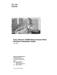
Figure 1-1 shows the location of some of the hardware features of the access point.
Figure 1-1
2
3
4
6
5
81180
1
Access Point Layout and Connectors
1
48-VDC power port
4
Mode button
2
Ethernet port (RJ-45)
5
Status LEDs
3
Cable lock slot
6
Antenna
Single Radio Operation
The access point contains a 2.4-GHz radio (IEEE 802.11b-compliant or IEEE 802.11g-compliant) in a
mini-PCI slot and two 2.2-dBi dipole integrated antennas. You can perform a field upgrade to the
mini-PCI radio and antennas to support new radio technologies, such as the 2.4-GHz
IEEE 802.11g-compliant radio.
Ethernet Port
The auto-sensing Ethernet port accepts an RJ-45 connector, linking the access point to your 10BASE-T
or 100BASE-T Ethernet LAN. The access point can receive power through the Ethernet cable from a
power injector, switch, or power patch panel. The Ethernet MAC address is printed on the label on the
back of the access point.
Cisco Aironet 1100 Series Access Point Hardware Installation Guide
1-2
OL-4309-02
Chapter 1
Overview
Hardware Features
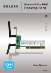
LEDs
The three LEDs on the top of the access point report Ethernet activity, association status, and radio
activity.
•
The Ethernet LED signals Ethernet traffic on the wired LAN, or Ethernet infrastructure. This LED
is normally green when an Ethernet cable is connected, and blinks green when a packet is received
or transmitted over the Ethernet infrastructure. The LED is off when the Ethernet cable is not
connected.
•
The status LED signals operational status. Steady green indicates that the access point is associated
with at least one wireless client. Blinking green indicates that the access point is operating normally
but is not associated with any wireless devices.
•
The radio LED signals wireless traffic over the radio interface. The light is normally off, but it blinks
green whenever a packet is received or transmitted over the access point radio.
Figure 1-2 shows the three status LEDs.
Figure 1-2
Access Point LEDs
Ethernet
Status
81597
Radio
Power Sources
The access point draws up to 4.9W of DC power and can receive power from an external power module
or through inline power using the Ethernet cable. Using inline power, you do not need to run a separate
power cord to the access point. The access point supports the following power sources:
•
Power supply (input 100–240 VAC, 50–60 Hz, output 48 VDC, 0.2A minimum)
•
Inline power from:
– Cisco Aironet Power Injector for 1100 and 1200 series access points
– A switch capable of providing inline power, such as the Cisco Catalyst 3500XL, 3550, 4000, or
6500
– An inline power patch panel, such as the Cisco Catalyst Inline Power Patch Panel
Cisco Aironet 1100 Series Access Point Hardware Installation Guide
OL-4309-02
1-3
Chapter 1
Overview
Hardware Features
UL 2043 Certification
The access point is encased in a durable plastic enclosure having adequate fire resistance and low
smoke-producing characteristics suitable for operation in a building's environmental air space, such as
above suspended ceilings, in accordance with Section 300-22(c) of the NEC, and with Sections 2-128,
12-010(3) and 12-100 of the Canadian Electrical Code, Part 1, C22.1.
Caution
Cisco Aironet 1100 series power injectors and the universal power supplies are not tested to UL 2043
and should not be placed in a building’s air-handling spaces, such as above suspended ceilings.
Anti-Theft Features
There are two methods of securing the access point to help prevent theft:
•
Security cable keyhole—You can use the security cable slot to secure the access point using a
standard security cable, such as those used on laptop computers.
•
Security hasp—When you mount the access point on a wall or ceiling using the mounting bracket
and the security hasp, you can lock the access point to the bracket with a padlock. Compatible
padlocks are Master Lock models 120T and 121T or equivalent.
Cisco Aironet 1100 Series Access Point Hardware Installation Guide
1-4
OL-4309-02
Chapter 1
Overview
Network Configuration Examples
Network Configuration Examples
This section describes the access point’s role in three common wireless network configurations. The
access point’s default configuration is as a root unit connected to a wired LAN or as the central unit in
an all-wireless network. The repeater role requires a specific configuration.
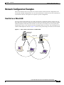
Root Unit on a Wired LAN
An access point connected directly to a wired LAN provides a connection point for wireless users. If
more than one access point is connected to the LAN, users can roam from one area of a facility to another
without losing their connection to the network. As users move out of range of one access point, they
automatically connect to the network (associate) through another access point. The roaming process is
seamless and transparent to the user. Figure 1-3 shows access points acting as root units on a wired LAN.
Figure 1-3
Access Points as Root Units on a Wired LAN
Access Point
(Root Unit)
Access Point
(Root Unit)
86301
81173
81173
Wired LAN
Cisco Aironet 1100 Series Access Point Hardware Installation Guide
OL-4309-02
1-5
Chapter 1
Overview
Network Configuration Examples
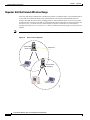
Repeater Unit that Extends Wireless Range
An access point can be configured as a stand-alone repeater to extend the range of your infrastructure or
to overcome an obstacle that blocks radio communication. The repeater forwards traffic between
wireless users and the wired LAN by sending packets to either another repeater or to an access point
connected to the wired LAN. The data is sent through the route that provides the best performance for
the client. Figure 1-4 shows an access point acting as a repeater. Consult the Cisco IOS Software
Configuration Guide for Cisco Aironet Access Points for instructions on setting up an access point as a
repeater.
Non-Cisco client devices might have difficulty communicating with repeater access points.
Figure 1-4
Access Point as Repeater
Wired LAN
Access Point
(Repeater)
86302
81173
Access Point
(Root Unit)
81173
Note
Cisco Aironet 1100 Series Access Point Hardware Installation Guide
1-6
OL-4309-02
Chapter 1
Overview
Network Configuration Examples
Central Unit in an All-Wireless Network
In an all-wireless network, an access point acts as a stand-alone root unit. The access point is not
attached to a wired LAN; it functions as a hub linking all stations together. The access point serves as
the focal point for communications, increasing the communication range of wireless users. Figure 1-5
shows an access point in an all-wireless network.
Figure 1-5
Access Point as Central Unit in All-Wireless Network
86300
81173
Access Point
(Root Unit)
Cisco Aironet 1100 Series Access Point Hardware Installation Guide
OL-4309-02
1-7
Chapter 1
Overview
Network Configuration Examples
Cisco Aironet 1100 Series Access Point Hardware Installation Guide
1-8
OL-4309-02
C H A P T E R
2
Installing the Access Point
This chapter describes the setup of the access point and includes the following sections:
•
Safety Information, page 2-2
•
Warnings, page 2-2
•
Basic Installation Guidelines, page 2-3
•
Unpacking the Access Point, page 2-3
•
Before Beginning the Installation, page 2-4
•
Installation Summary, page 2-4
•
Connecting the Ethernet and Power Cables, page 2-5
Cisco Aironet 1100 Series Access Point Hardware Installation Guide
OL-4309-02
2-1
Chapter 2
Installing the Access Point
Safety Information
Safety Information
Follow the guidelines in this section to ensure proper operation and safe use of the access point.
FCC Safety Compliance Statement
The FCC with its action in ET Docket 96-8 has adopted a safety standard for human exposure to radio
frequency (RF) electromagnetic energy emitted by FCC certified equipment. When used with approved
Cisco Aironet antennas, Cisco Aironet products meet the uncontrolled environmental limits found in
OET-65 and ANSI C95.1, 1991. Proper installation of this radio according to the instructions found in
this manual will result in user exposure that is substantially below the FCC recommended limits.
General Safety Guidelines
•
Do not touch or move antenna(s) while the unit is transmitting or receiving.
•
Do not hold any component containing a radio so that the antenna is very close to or touching any
exposed parts of the body, especially the face or eyes, while transmitting.
•
The use of wireless devices in hazardous locations is limited to the constraints posed by the local
codes, the national codes, and the safety directors of such environments.
Warnings
Translated versions of the following safety warnings are provided in Appendix A, “Translated Safety
Warnings.”
Warning
In order to comply with FCC radio frequency (RF) exposure limits, dipole antennas should be located
at a minimum of 7.9 inches (20 cm) or more from the body of all persons.
Warning
Do not operate your wireless network device near unshielded blasting caps or in an explosive
environment unless the device has been modified to be especially qualified for such use.
Warning
Do not work on the system or connect or disconnect cables during periods of lightning activity.
Warning
Read the installation instructions before you connect the system to its power source.
Warning
This product relies on the building's installation for short-circuit (overcurrent) protection. Ensure that
a fuse or circuit breaker no larger than 120 VAC, 15A U.S. (240 VAC, 10A international) is used on the
phase conductors (all current-carrying conductors).
Cisco Aironet 1100 Series Access Point Hardware Installation Guide
2-2
OL-4309-02
Chapter 2
Installing the Access Point
Unpacking the Access Point
Unpacking the Access Point
Follow these steps to unpack the access point:
Step 1
Open the shipping container and carefully remove the contents.
Step 2
Return all packing materials to the shipping container and save it.
Step 3
Ensure that all items listed in the “Package Contents” section are included in the shipment. Check each
item for damage. If any item is damaged or missing, notify your authorized Cisco sales representative.
Package Contents
Each access point package contains the following items:
•
Access point power pack
•
Wall or ceiling mounting bracket
•
Security hasp adapter
•
Cubical partition mounting bracket assembly
•
Horizontal surface mounting holster
•
Mounting hardware kit
•
Product registration card
Basic Installation Guidelines
Because the access point is a radio device, it is susceptible to common causes of interference that can
reduce throughput and range. Follow these basic guidelines to ensure the best possible performance:
•
Install the access point in an area where large steel structures such as shelving units, bookcases, and
filing cabinets do not block the radio signals to and from the access point.
•
Install the access point away from microwave ovens. Microwave ovens operate on the same
frequency as the access point and can cause signal interference.
Cisco Aironet 1100 Series Access Point Hardware Installation Guide
OL-4309-02
2-3
Chapter 2
Installing the Access Point
Before Beginning the Installation
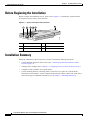
Before Beginning the Installation
Before you begin the installation process, please refer to Figure 2-1 to familiarize yourself with the
access point’s layout, features, and connectors.
Figure 2-1
2
3
4
6
5
81180
1
Access Point Layout and Connectors
1
48-VDC power port
4
Mode button
2
Ethernet port (RJ-45)
5
Status LEDs
3
Cable lock slot
6
Antenna
Installation Summary
During the installation of the access point, you need to perform the following operations:
•
Connect Ethernet and power cables (refer to the “Connecting the Ethernet and Power Cables”
section on page 2-5).
•
Configure basic settings (refer to Chapter 3, “Configuring the Access Point for the First Time”).
•
Configure security and other access point options.
•
Use the mounting brackets or docking cradle to locate the access point on a convenient flat
horizontal or vertical surface, such as a desktop, book shelf, file cabinet, cubicle wall, room wall, or
the room ceiling. For additional information, refer to Chapter 6, “Mounting Instructions.”
Cisco Aironet 1100 Series Access Point Hardware Installation Guide
2-4
OL-4309-02
Chapter 2
Installing the Access Point
Connecting the Ethernet and Power Cables
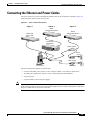
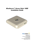
Connecting the Ethernet and Power Cables
The access point receives power through the Ethernet cable or an external power module. Figure 2-2
shows the power options for the access point.
Figure 2-2
Access Point Power Options
Option 1
Option 2
Option 3
Switch
(without inline power)
Switch with
inline power
SYST
RPS
STAT
UTIL DUPLX
SPEED
MODE
1
2
3
4
5
6
7
8
9
10Base-T
10
11
12
Switch
(without inline power)
/ 100Base-TX
13
14
15
16
17
18
19
20
Catalyst 2950
21
22
23
24
SERIES
100Base-FX
23
24
SYST
RPS
STAT
UTIL DUPLX
MODE
SYST
RPS
STAT
UTIL DUPLX
SPEED
MODE
1
2
3
4
5
6
7
8
9
10Base-T
10
11
12
SPEED
1
2
3
4
5
6
7
8
9
10Base-T
10
11
12
/ 100Base-TX
13
14
15
16
17
18
19
20
Catalyst 2950
21
22
23
24
SERIES
100Base-FX
23
24
/ 100Base-TX
13
14
15
16
17
18
19
20
Catalyst 2950
21
22
23
24
SERIES
100Base-FX
23
24
Inline Power
Patch Panel
O
T OR
W
T
E
K
Power injector
SYST
UTIL DUPLX
SPEED
E
OG
T ID
R
B
/
P
A
MODE
N
RPS
STAT
Power
cord
Access Point
81596
81173
Universal
power supply
Option 4
The access point power options are listed below:
Note
•
A switch with inline power, such as a Cisco Catalyst 3500XL, 3550, 4000, or 6500 switch
•
An inline power patch panel, such as a Cisco Catalyst Inline Power Patch Panel
•
A power injector
•
A power module (Universal power supply)
If you use in-line power from a switch or patch panel, do not connect the power module to the access
point. Using two power sources on the access point might cause the switch or patch panel to shut down
the port to which the access point is connected.
Cisco Aironet 1100 Series Access Point Hardware Installation Guide
OL-4309-02
2-5
Chapter 2
Installing the Access Point
Connecting the Ethernet and Power Cables
Connecting to an Ethernet Network with an Inline Power Source
Follow these steps to connect the access point to the Ethernet LAN when you have an inline power
source:
Step 1
Connect the Ethernet cable to the RJ-45 Ethernet connector labeled Ethernet on the access point.
Step 2
Connect the other end of the Ethernet cable to one of the following:
•
A switch with inline power, such as a Cisco Catalyst 3500XL, 3550, 4000, or 6500 switch.
•
An inline power switch panel, such as a Cisco Catalyst Inline Power Patch Panel.
•
The end of a Cisco Aironet power injector labeled To AP/Bridge. Connect the other end labeled To
Network to the 10/100 Ethernet LAN.
Caution
The Cisco Aironet Power Injector for the 1100 and 1200 series is designed for use with 1100 series or
1200 series access points only. Using the power injector with other Ethernet-ready devices can damage
the equipment.
Caution
The Cisco Aironet Power Injector for the 1100 and 1200 series is not tested to UL 2043 and should not
be placed in a building's environmental air space, such as above suspended ceilings.
Note
If you use a power supply or power injector to power the access point, you must use the power supply
included with your access point and the Cisco Aironet Power Injector for the 1100 and 1200 series access
points.
Connecting to an Ethernet Network with Local Power
Follow these steps to connect the access point to an Ethernet LAN when you are using a local power
source:
Step 1
Connect the Ethernet cable to the RJ-45 Ethernet connector labeled Ethernet on the access point.
Step 2
Plug the other end of the Ethernet cable into an unpowered Ethernet port on your network.
Step 3
Connect the power module’s output connector to the 48-VDC power port labeled 48VDC on the access
point.
Step 4
Plug the other end of the power module into an approved 100- to 240-VAC outlet.
Cisco Aironet 1100 Series Access Point Hardware Installation Guide
2-6
OL-4309-02
Chapter 2
Installing the Access Point
Connecting the Ethernet and Power Cables
Powering Up the Access Point
When power is applied to the access point, it begins a routine power-up sequence that you can monitor
by observing the three LEDs on top of the access point. After you observe all three LEDs turning green
to indicate the starting of the IOS operating system, the Status LED blinks green signifying that IOS is
operational. When in an operational status, the Ethernet LED is steady green when no traffic is being
passed and dark during periods when traffic is being passed. The sequence takes about 1 minute to
complete. Refer to Chapter 8, “Troubleshooting,” for LED descriptions.
When the sequence is complete, you are ready to obtain the access point’s IP address and perform an
initial configuration. Refer to Chapter 3, “Configuring the Access Point for the First Time,” for
instructions on assigning basic settings to the access point.
Cisco Aironet 1100 Series Access Point Hardware Installation Guide
OL-4309-02
2-7
Chapter 2
Installing the Access Point
Connecting the Ethernet and Power Cables
Cisco Aironet 1100 Series Access Point Hardware Installation Guide
2-8
OL-4309-02
C H A P T E R
3
Configuring the Access Point for the First Time
This chapter describes how to configure basic settings on your access point for the first time. The
contents of this chapter are similar to the instructions in the quick start guide that shipped with your
access point. You can configure all the settings described in this chapter using the CLI, but it might be
simplest to browse to the access point’s web-browser interface to complete the initial configuration and
then use the CLI to enter additional settings for a more detailed configuration.
This chapter contains these sections:
•
Before You Start, page 3-2
•
Obtaining and Assigning an IP Address, page 3-3
•
Connecting to the Access Point Locally, page 3-3
•
Assigning Basic Settings, page 3-4
•
Protecting Your Wireless LAN, page 3-8
•
Using the IP Setup Utility, page 3-8
•
Assigning an IP Address Using the CLI, page 3-11
•
Using a Telnet Session to Access the CLI, page 3-11
Cisco Aironet 1100 Series Access Point Hardware Installation Guide
OL-4309-02
3-1
Chapter 3
Configuring the Access Point for the First Time
Before You Start
Before You Start
Before you install the access point, make sure you are using a computer connected to the same network
as the access point, and obtain the following information:
•
The following information from your network system administrator:
– A system name
– The case-sensitive wireless service set identifier (SSID) for your radio network
– If not connected to a DHCP server, a unique IP address for your access point (such as
172.17.255.115)
– If the access point is not on the same subnet as your PC, a default gateway address and subnet
mask
– A Simple Network Management Protocol (SNMP) community name and the SNMP file
attribute (if SNMP is in use)
•
If you use IPSU to find or assign the access point IP address, the MAC address from the label on the
bottom of the access point (such as 00164625854c)
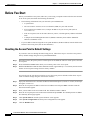
Resetting the Access Point to Default Settings
If you need to start over during the initial setup process, follow these steps to reset the access point to
factory default settings using the access point MODE button:
Step 1
Disconnect power (the power jack for external power or the Ethernet cable for in-line power) from the
access point.
Step 2
Press and hold the MODE button while you reconnect power to the access point.
Step 3
Hold the MODE button until the Status LED turns amber (approximately 1 to 2 seconds), and release the
button. All access point settings return to factory defaults.
You can also use the web-browser interface to reset the access point to defaults. Follow these steps to
return to default settings using the web-browser interface:
Step 1
Open your Internet browser. You must use Microsoft Internet Explorer (version 5.x or later) or Netscape
Navigator (version 4.x).
Step 2
Enter the access point’s IP address in the browser address line and press Enter. An Enter Network
Password window appears.
Step 3
Enter your username in the User Name field. The default username is Cisco.
Step 4
Enter the access point password in the Password field and press Enter. The default password is Cisco.
The Summary Status page appears.
Step 5
Click System Software and the System Software screen appears.
Step 6
Click System Configuration and the System Configuration screen appears.
Step 7
Click the Default button.
Cisco Aironet 1100 Series Access Point Hardware Installation Guide
3-2
OL-4309-02
Chapter 3
Configuring the Access Point for the First Time
Obtaining and Assigning an IP Address
Note
If the access point is configured with a static IP address, the IP address will not be changed.
Obtaining and Assigning an IP Address
To browse to the access point’s Express Setup page, you must either obtain or assign the access point’s
IP address using one of the following methods:
•
Use default address 10.0.0.1 when you connect to the access point locally. For detailed instructions,
see the “Connecting to the Access Point Locally” section on page 3-3.
•
Use a DHCP server (if available) to automatically assign an IP address. You can find out the
DHCP-assigned IP address using one of the following methods:
– Provide your organization’s network administrator with your access point’s Media Access
Control (MAC) address. Your network administrator will query the DHCP server using the
MAC address to identify the IP address. The access point’s MAC address is on label attached to
the bottom of the access point.
– Use the Cisco IP Setup Utility (IPSU) to identify the assigned address. You can also use IPSU
to assign an IP address to the access point if it did not receive an IP address from the DHCP
server. IPSU runs on most Microsoft Windows operating systems: Windows 9x, 2000, Me, NT,
and XP.
You can download IPSU from the Software Center on Cisco.com (For additional information,
refer to the “Obtaining and Installing IPSU” section on page 3-8).
Connecting to the Access Point Locally
If you need to configure the access point locally (without connecting the access point to a wired LAN),
you can connect a PC to its Ethernet port using a Category 5 Ethernet cable. You can use a local
connection to the Ethernet port much as you would use a serial port connection.
Note
You do not need a special crossover cable to connect your PC to the access point; you can use
either a straight-through cable or a crossover cable.
If the access point is configured with default values and not connected to a DHCP server or cannot obtain
an IP address, it defaults to IP address 10.0.0.1 and becomes a mini-DHCP server. In that capacity, the
access point provides up to twenty IP addresses between 10.0.0.11 and 10.0.0.30 to the following
devices:
•
An Ethernet-capable PC connected to its Ethernet port
•
Wireless client devices configured to use either no SSID or tsunami as the SSID, and with all
security settings disabled
The mini-DHCP server feature is disabled automatically when you assign a static IP address to the access
point.
Cisco Aironet 1100 Series Access Point Hardware Installation Guide
OL-4309-02
3-3
Chapter 3
Configuring the Access Point for the First Time
Assigning Basic Settings
Caution
When an access point with default settings is connected on a wired LAN and does not receive an IP
address from a DHCP server, the access point provides an IP address to any DHCP requests it receives.
Follow these steps to connect to the access point locally:
Step 1
Make sure that the PC you intend to use is configured to obtain an IP address automatically, or manually
assign it an IP address from 10.0.0.2 to 10.0.0.10. Connect your PC to the access point using a Category
5 Ethernet cable. You can use either a crossover cable or a straight-through cable.
Step 2
Power up the access point.
Step 3
Follow the steps in the “Assigning Basic Settings” section on page 3-4. If you make a mistake and need
to start over, follow the steps in the “Resetting the Access Point to Default Settings” section on page 3-2.
Step 4
After configuring the access point, remove the Ethernet cable from your PC and connect the access point
to your wired LAN.
Note
When you connect your PC to the access point or reconnect your PC to the wired LAN, you might need
to release and renew the IP address on the PC. On most PCs, you can perform a release and renew by
rebooting your PC or by entering ipconfig /release and ipconfig /renew commands in a command
prompt window. Consult your PC operating instructions for detailed instructions.
Assigning Basic Settings
After you determine or assign the access point’s IP address, you can browse to the access point’s Express
Setup page and perform an initial configuration. Follow these steps:
Step 1
Open your Internet browser. You must use Microsoft Internet Explorer (version 5.x or later) or Netscape
Navigator (version 4.x).
Step 2
Enter the access point’s IP address in the browser address line and press Enter. An Enter Network
Password screen appears.
Step 3
Press Tab to bypass the Username field and advance to the Password field.
Step 4
Enter the case-sensitive password Cisco and press Enter. The Summary Status page appears. Figure 3-1
shows the Summary Status page.
Cisco Aironet 1100 Series Access Point Hardware Installation Guide
3-4
OL-4309-02
Chapter 3
Configuring the Access Point for the First Time
Assigning Basic Settings
Figure 3-1
Step 5
Summary Status Page
Click Express Setup. The Express Setup screen appears. Figure 3-2 shows the Express Setup page.
Figure 3-2
Express Setup Page
Cisco Aironet 1100 Series Access Point Hardware Installation Guide
OL-4309-02
3-5
Chapter 3
Configuring the Access Point for the First Time
Assigning Basic Settings
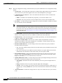
Step 6
Enter the configuration settings you obtained from your system administrator. The configurable settings
include:
•
System Name— The system name, while not an essential setting, helps identify the access point on
your network. The system name appears in the titles of the management system pages.
•
Configuration Server Protocol—Click on the button that matches the network’s method of IP
address assignment.
– DHCP—IP addresses are automatically assigned by your network’s DHCP server.
– Static IP—The access point uses a static IP address that you enter in the IP address field.
•
Note
IP Address—Use this setting to assign or change the access point’s IP address. If DHCP is enabled
for your network, leave this field blank.
If the access point’s IP address changes while you are configuring the access point using the
web-browser interface or a Telnet session over the wired LAN, you lose your connection to the
access point. If you lose your connection, reconnect to the access point using its new IP address.
Follow the steps in the “Resetting the Access Point to Default Settings” section on page 3-2 if
you need to start over.
•
IP Subnet Mask—Enter the IP subnet mask provided by your network administrator so the IP
address can be recognized on the LAN. If DHCP is enabled, leave this field blank.
•
Default Gateway—Enter the default gateway IP address provided by your network administrator.
If DHCP is enabled, leave this field blank.
•
Radio Service Set ID (SSID)—Enter the case-sensitive SSID (32 alphanumeric characters
maximum) provided by your network administrator. The SSID is a unique identifier that client
devices use to associate with the access point.
•
Broadcast SSID in Beacon—Use this setting to allow devices that do not specify an SSID to
associate with the access point.
– Yes—This is the default setting; it allows devices that do not specify an SSID to associate with
the access point.
– No—Devices must specify an SSID to associate with the access point. With No selected, the
SSID used by the client devices must match exactly the access point’s SSID.
•
Role in Radio Network—Click on the button that describes the role of the access point on your
network. Select Access Point (Root) if your access point is connected to the wired LAN. Select
Repeater (Non-Root) if it is not connected to the wired LAN.
•
Optimize Radio Network for—Use this setting to select either preconfigured settings for the access
point radio or customized settings for the access point radio.
– Throughput—Maximizes the data volume handled by the access point but might reduce its
range.
– Range—Maximizes the access point’s range but might reduce throughput.
– Custom—The access point uses settings you enter on the Network Interfaces: Radio-802.11b
Settings page. Clicking Custom takes you to the Network Interfaces: Radio-802.11b Settings
page.
•
Aironet Extensions—Enable this setting if there are only Cisco Aironet devices on your wireless
LAN.
Cisco Aironet 1100 Series Access Point Hardware Installation Guide
3-6
OL-4309-02
Chapter 3
Configuring the Access Point for the First Time
Assigning Basic Settings
•
Step 7
SNMP Community—If your network is using SNMP, enter the SNMP Community name provided
by your network administrator and select the attributes of the SNMP data (also provided by your
network administrator).
Click Apply to save your settings. If you changed the IP address, you lose your connection to the access
point. Browse to the new IP address to reconnect to the access point.
Your access point is now running but probably requires additional configuring to conform to your
network’s operational and security requirements. Consult the chapters in this manual for the information
you need to complete the configuration.
Note
You can restore the access point to its factory defaults by unplugging the power jack and
plugging it back in while holding down the Mode button for a few seconds, or until the Status
LED turns amber.
Default Settings on the Express Setup Page
Table 3-1 lists the default settings for the settings on the Express Setup page.
Table 3-1
Default Settings on the Express Setup Page
Setting
Default
System Name
ap
Configuration Server Protocol
DHCP
IP Address
Assigned by DHCP by default; if
DHCP is disabled, the default
setting is 10.0.0.1
IP Subnet Mask
Assigned by DHCP by default; if
DHCP is disabled, the default
setting is 255.255.255.224
Default Gateway
Assigned by DHCP by default; if
DHCP is disabled, the default
setting is 0.0.0.0
Radio Service Set ID (SSID)
tsunami
Broadcast SSID in Beacon
Yes1
Role in Radio Network
Access point (root)
Optimize Radio Network for
Throughput
Aironet Extensions
Enable
SNMP Community
defaultCommunity
1. When you assign multiple SSIDs, this setting no longer appears.
Cisco Aironet 1100 Series Access Point Hardware Installation Guide
OL-4309-02
3-7
Chapter 3
Configuring the Access Point for the First Time
Protecting Your Wireless LAN
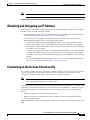
Protecting Your Wireless LAN
After you assign basic settings to your access point, you need to configure security settings to prevent
unauthorized access to your network. Because it is a radio device, the access point can communicate
beyond the physical boundaries of your building. Refer to the Cisco IOS Software Configuration Guide
for Cisco Aironet Access Points for information on how to configure some combination of these security
features to protect you network from intruders:
•
Unique SSIDs that are not broadcast in the access point beacon
•
WEP and additional WEP features, such as TKIP and broadcast key rotation
•
Dynamic WEP and client authentication
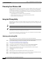
Using the IP Setup Utility
IPSU enables you to find the access point’s IP address when it has been assigned by a DHCP server. You
can also use IPSU to set the access point’s IP address and SSID if they have not been changed from the
default settings.
Note
IPSU can be used only on the following operating systems: Windows 95, 98, NT, 2000, ME, or XP.
Tip
Another simple way to find the access point’s IP address is to look on the Status screen in the Aironet
Client Utility on a client device associated to the access point.
The sections below explain how to install the utility, how to use it to find the access point’s IP address,
and how to use it to set the IP address and the SSID.
Obtaining and Installing IPSU
IPSU is available on the Cisco web site. Follow these steps to obtain and install IPSU:
Step 1
Use your Internet browser to access the Cisco Software Center at the following URL:
http://www.cisco.com/public/sw-center/sw-wireless.shtml
Step 2
Click Option 2: Aironet Wireless Software Display Tables.
Step 3
Locate the access point firmware and utilities section and click Cisco Aironet 1100 Series.
Step 4
Click IPSUvxxxxxx.exe. The vxxxxxx identifies the software package version number.
Step 5
On the Encryption Authorization Form, enter the requested information, read the encryption
information, and check the boxes that apply.
Step 6
Click Submit.
Step 7
Read and accept the terms and conditions of the Software License Agreement.
Step 8
Download and save the file to a temporary directory on your hard drive and then exit the Internet browser.
Step 9
Double-click IPSUvxxxxxx.exe in the temporary directory to expand the file.
Cisco Aironet 1100 Series Access Point Hardware Installation Guide
3-8
OL-4309-02
Chapter 3
Configuring the Access Point for the First Time
Using the IP Setup Utility
Step 10
Double-click Setup.exe and follow the steps provided by the installation wizard to install IPSU.
The IPSU icon appears on your computer desktop.
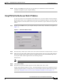
Using IPSU to Find the Access Point’s IP Address
If your access point receives an IP address from a DHCP server, you can use IPSU to find its IP address.
Because IPSU sends a reverse-ARP request based on the access point MAC address, you must run IPSU
from a computer on the same subnet as the access point. Follow these steps to find the access point’s IP
address:
Step 1
Double-click the IPSU icon on your computer desktop to start the utility. The IPSU screen appears (see
Figure 3-3).
Figure 3-3
IPSU Get IP Address Screen
Step 2
When the utility window opens, make sure the Get IP addr radio button in the Function box is selected.
Step 3
Enter the access point’s MAC address in the Device MAC ID field. The access point’s MAC address is
printed on the label on the bottom of the unit. It should contain six pairs of hexadecimal digits. Your
access point’s MAC address might look like the following example:
000164xxxxxx
Note
The MAC address field is not case-sensitive.
Step 4
Click Get IP Address.
Step 5
When the access point’s IP address appears in the IP Address field, write it down.
If IPSU reports that the IP address is 10.0.0.1, the default IP address, then the access point did not receive
a DHCP-assigned IP address. To change the access point IP address from the default value using IPSU,
refer to the “Using IPSU to Set the Access Point’s IP Address and SSID” section on page 3-10.
Cisco Aironet 1100 Series Access Point Hardware Installation Guide
OL-4309-02
3-9
Chapter 3
Configuring the Access Point for the First Time
Using the IP Setup Utility
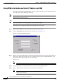
Using IPSU to Set the Access Point’s IP Address and SSID
If you want to change the default IP address (10.0.0.1) of the access point, you can use IPSU. You can
also set the access point’s SSID at the same time.
Note
The computer you use to assign an IP address to the access point must have an IP address in the same
subnet as the access point (10.0.0.x).
Note
IPSU can change the access point’s IP address and SSID only from their default settings. After the IP
address and SSID have been changed, IPSU cannot change them again.
Follow these steps to assign an IP address and an SSID to the access point:
Step 1
Double-click the IPSU icon on your computer desktop to start the utility.
Step 2
Click the Set Parameters radio button in the Function box (see Figure 3-4).
Figure 3-4
Step 3
IPSU Set Parameters Screen
Enter the access point’s MAC address in the Device MAC ID field. The access point’s MAC address is
printed on the label on the bottom of the unit. It should contain six pairs of hexadecimal digits. Your
access point’s MAC address might look like this example:
004096xxxxxx
Note
The MAC address field is not case-sensitive.
Step 4
Enter the IP address you want to assign to the access point in the IP Address field.
Step 5
Enter the SSID you want to assign to the access point in the SSID field.
Note
You cannot set the SSID without also setting the IP address. However, you can set the IP address
without setting the SSID.
Cisco Aironet 1100 Series Access Point Hardware Installation Guide
3-10
OL-4309-02
Chapter 3
Configuring the Access Point for the First Time
Assigning an IP Address Using the CLI
Step 6
Click Set Parameters to change the access point’s IP address and SSID settings.
Step 7
Click Exit to exit IPSU.
Assigning an IP Address Using the CLI
When you connect the access point to the wired LAN, the access point links to the network using a bridge
virtual interface (BVI) that it creates automatically. Instead of tracking separate IP addresses for the
access point’s Ethernet and radio ports, the network uses the BVI.
When you assign an IP address to the access point using the CLI, you must assign the address to the BVI.
Beginning in privileged EXEC mode, follow these steps to assign an IP address to the access point’s
BVI:
Command
Purpose
Step 1
configure terminal
Enter global configuration mode.
Step 2
interface bvi1
Enter interface configuration mode for the BVI.
Step 3
ip address address
mask
Assign an IP address and address mask to the BVI. This step
automatically saves the running configuration to the startup
configuration.
Note
You lose your connection to the access point when you
assign a new IP address to the BVI. If you need to
continue configuring the access point, use the new IP
address to open another Telnet session to the access
point.
Using a Telnet Session to Access the CLI
Follow these steps to browse to access the CLI using a Telnet session. These steps are for a PC running
Microsoft Windows with a Telnet terminal application. Check your PC operating instructions for
detailed instructions for your operating system.
Step 1
Select Start > Programs > Accessories > Telnet.
If Telnet is not listed in your Accessories menu, select Start > Run, type Telnet in the entry field, and
press Enter.
Step 2
When the Telnet window appears, click Connect and select Remote System.
Note
Step 3
In Windows 2000, the Telnet window does not contain drop-down menus. To start the Telnet
session in Windows 2000, type open followed by the access point’s IP address.
In the Host Name field, type the access point’s IP address and click Connect.
Cisco Aironet 1100 Series Access Point Hardware Installation Guide
OL-4309-02
3-11
Chapter 3
Configuring the Access Point for the First Time
Using a Telnet Session to Access the CLI
Cisco Aironet 1100 Series Access Point Hardware Installation Guide
3-12
OL-4309-02
C H A P T E R
4
Using the Web-Browser Interface
This chapter describes the web-browser interface that you can use to configure the access point. It
contains these sections:
•
Using the Web-Browser Interface for the First Time, page 4-2
•
Using the Management Pages in the Web-Browser Interface, page 4-2
•
Using Online Help, page 4-5
The web-browser interface contains management pages that you use to change access point settings,
upgrade firmware, and monitor and configure other wireless devices on the network.
Note
The access point web-browser interface is fully compatible with Microsoft Internet Explorer (version
5.x or later) or Netscape Navigator (version 4.x).
Cisco Aironet 1100 Series Access Point Hardware Installation Guide
OL-4309-02
4-1
Chapter 4
Using the Web-Browser Interface
Using the Web-Browser Interface for the First Time
Using the Web-Browser Interface for the First Time
Use the access point’s IP address to browse to the management system. See the “Obtaining and
Assigning an IP Address” section on page 3-3 for instructions on assigning an IP address to the access
point.
Follow these steps to begin using the web-browser interface:
Step 1
Start the browser.
Step 2
Enter the access point’s IP address in the browser Location field (Netscape Communicator) or Address
field (Internet Explorer) and press Enter. The Summary Status page appears.
Using the Management Pages in the Web-Browser Interface
The system management pages use consistent techniques to present and save configuration information.
A navigation bar is on the left side of the page, and configuration action buttons appear at the bottom.
You use the navigation bar to browse to other management pages, and you use the configuration action
buttons to save or cancel changes to the configuration.
Note
Changes are applied only when you click Apply. It’s important to remember that clicking your browser’s
Back button returns you to the previous page without saving any changes you have made. Clicking
Cancel cancels any changes you made on the page and keeps you on that page.
Figure 4-1 shows the web-browser interface home page.
Cisco Aironet 1100 Series Access Point Hardware Installation Guide
4-2
OL-4309-02
Chapter 4
Using the Web-Browser Interface
Using the Management Pages in the Web-Browser Interface
Figure 4-1
Web-Browser Interface Home Page
Using Action Buttons
Table 4-1 lists the page links and buttons that appear on most management pages.
Table 4-1
Common Buttons on Management Pages
Button/Link
Description
Navigation Links
Home
Displays access point status page with information on the number of radio
devices associated to the access point, the status of the Ethernet and radio
interfaces, and a list of recent access point activity.
Express Setup
Displays the Express Setup page that includes basic settings such as system
name, IP address, and SSID.
Network Map
Displays a list of infrastructure devices on your wireless LAN.
Association
Displays a list of all devices on your wireless LAN, listing their system names,
network roles, and parent-client relationships.
Cisco Aironet 1100 Series Access Point Hardware Installation Guide
OL-4309-02
4-3
Chapter 4
Using the Web-Browser Interface
Using the Management Pages in the Web-Browser Interface
Table 4-1
Common Buttons on Management Pages (continued)
Button/Link
Description
Network Interfaces
Displays status and statistics for the Ethernet and radio interfaces and provides
links to configuration pages for each interface.
Security
Displays a summary of security settings and provides links to security
configuration pages.
Services
Displays status for several access point features and links to configuration
pages for Telnet/SSH, CDP, Domain Name Server, Filters, Proxy Mobile IP,
QoS, SNMP, SNTP, and VLANs.
System Software
Displays the version number of the firmware that the access point is running
and provides links to configuration pages for upgrading and managing
firmware.
Event Log
Displays the access point event log and provides links to configuration pages
where you can select events to be included in traps, set event severity levels,
and set notification methods.
Configuration Action Buttons
Apply
Saves changes made on the page and remains on the page.
Refresh
Updates status information or statistics displayed on a page.
Cancel
Discards changes to the page and remains on the page.
Back
Discards any changes made to the page and returns to the previous page.
Cisco Aironet 1100 Series Access Point Hardware Installation Guide
4-4
OL-4309-02
Chapter 4
Using the Web-Browser Interface
Using Online Help
Character Restrictions in Entry Fields
Because the 1100 series access point uses Cisco IOS software, there are certain characters that you
cannot use in the entry fields on the web-browser interface. Table 4-2 lists the prohibited characters and
the fields in which you cannot use them.
Table 4-2
Prohibited Characters for Web-Browser Interface Entry Fields
Entry Field Type
Prohibited Characters
Password entry fields
?
“
$
[
+
All other entry fields
?
“
$
[
+
You also cannot use these
three characters as the
first character in an entry
field:
!
#
;
Using Online Help
Click the help icon at the top of any page in the web-browser interface to display online help. Figure 4-2
shows the print and help icons.
Figure 4-2
Print and Help Icons
When a help page appears in a new browser window, use the Select a topic drop-down menu to display
the help index or instructions for common configuration tasks, such as configuring VLANs.
Cisco Aironet 1100 Series Access Point Hardware Installation Guide
OL-4309-02
4-5
Chapter 4
Using the Web-Browser Interface
Using Online Help
Cisco Aironet 1100 Series Access Point Hardware Installation Guide
4-6
OL-4309-02
C H A P T E R
5
Using the Command-Line Interface
This chapter describes the IOS command-line interface (CLI) that you can use to configure your access
point. It contains these sections:
•
IOS Command Modes, page 5-2
•
Getting Help, page 5-3
•
Abbreviating Commands, page 5-3
•
Using no and default Forms of Commands, page 5-3
•
Understanding CLI Messages, page 5-4
•
Using Command History, page 5-4
•
Using Editing Features, page 5-6
•
Searching and Filtering Output of show and more Commands, page 5-8
•
Accessing the CLI, page 5-9
Cisco Aironet 1100 Series Access Point Hardware Installation Guide
OL-4309-02
5-1
Chapter 5
Using the Command-Line Interface
IOS Command Modes
IOS Command Modes
The Cisco IOS user interface is divided into many different modes. The commands available to you
depend on which mode you are currently in. Enter a question mark (?) at the system prompt to obtain a
list of commands available for each command mode.
When you start a session on the access point, you begin in user mode, often called user EXEC mode.
Only a limited subset of the commands are available in user EXEC mode. For example, most of the user
EXEC commands are one-time commands, such as show commands, which show the current
configuration status, and clear commands, which clear counters or interfaces. The user EXEC
commands are not saved when the access point reboots.
To have access to all commands, you must enter privileged EXEC mode. Normally, you must enter a
password to enter privileged EXEC mode. From this mode, you must enter privileged EXEC mode
before you can enter the global configuration mode.
Using the configuration modes (global, interface, and line), you can make changes to the running
configuration. If you save the configuration, these commands are stored and used when the access point
reboots. To access the various configuration modes, you must start at global configuration mode. From
global configuration mode, you can enter interface configuration mode and line configuration mode.
Table 5-1 describes the main command modes, how to access each one, the prompt you see in that mode, and
how to exit the mode. The examples in the table use the host name ap.
Table 5-1
Command Mode Summary
Mode
Access Method
Prompt
Exit Method
About This Mode
User EXEC
Begin a session with
your access point.
ap>
Enter logout or quit.
Use this mode to
•
Change terminal settings
•
Perform basic tests
•
Display system
information.
Privileged EXEC
While in user EXEC
mode, enter the
enable command.
ap#
Enter disable to exit.
Global configuration
While in privileged
EXEC mode, enter
the configure
command.
ap(config)#
To exit to privileged
Use this mode to configure
EXEC mode, enter exit or parameters that apply to the
end, or press Ctrl-Z.
entire access point.
Interface
configuration
While in global
configuration mode,
enter the interface
command (with a
specific interface).
ap(config-if)#
Use this mode to configure
To exit to global
configuration mode, enter parameters for the Ethernet
interfaces.
exit. To return to
privileged EXEC mode,
press Ctrl-Z or enter end.
Use this mode to verify
commands. Use a password to
protect access to this mode.
Cisco Aironet 1100 Series Access Point Hardware Installation Guide
5-2
OL-4309-02
Chapter 5
Using the Command-Line Interface
Getting Help
Getting Help
You can enter a question mark (?) at the system prompt to display a list of commands available for each
command mode. You can also obtain a list of associated keywords and arguments for any command, as
shown in Table 5-2.
Table 5-2
Help Summary
Command
Purpose
help
Obtain a brief description of the help system in any command mode.
abbreviated-command-entry?
Obtain a list of commands that begin with a particular character string.
For example:
ap# di?
dir disable disconnect
abbreviated-command-entry<Tab>
Complete a partial command name.
For example:
ap# sh conf<tab>
ap# show configuration
?
List all commands available for a particular command mode.
For example:
ap> ?
command ?
List the associated keywords for a command.
For example:
ap> show ?
command keyword ?
List the associated arguments for a keyword.
For example:
ap(config)# cdp holdtime ?
<10-255> Length of time (in sec) that receiver must keep this packet
Abbreviating Commands
You have to enter only enough characters for the access point to recognize the command as unique. This
example shows how to enter the show configuration privileged EXEC command:
ap# show conf
Using no and default Forms of Commands
Most configuration commands also have a no form. In general, use the no form to disable a feature or
function or reverse the action of a command. For example, the no shutdown interface configuration
command reverses the shutdown of an interface. Use the command without the keyword no to re-enable
a disabled feature or to enable a feature that is disabled by default.
Cisco Aironet 1100 Series Access Point Hardware Installation Guide
OL-4309-02
5-3
Chapter 5
Using the Command-Line Interface
Understanding CLI Messages
Configuration commands can also have a default form. The default form of a command returns the
command setting to its default. Most commands are disabled by default, so the default form is the same
as the no form. However, some commands are enabled by default and have variables set to certain default
values. In these cases, the default command enables the command and sets variables to their default
values.
Understanding CLI Messages
Table 5-3 lists some error messages that you might encounter while using the CLI to configure your
access point.
Table 5-3
Common CLI Error Messages
Error Message
Meaning
How to Get Help
% Ambiguous command:
"show con"
You did not enter enough characters Re-enter the command followed by a question mark (?)
for your access point to recognize the with a space between the command and the question
command.
mark.
The possible keywords that you can enter with the
command are displayed.
You did not enter all the keywords or Re-enter the command followed by a question mark (?)
values required by this command.
with a space between the command and the question
mark.
% Incomplete command.
The possible keywords that you can enter with the
command are displayed.
% Invalid input detected
at ‘^’ marker.
You entered the command
incorrectly. The caret (^) marks the
point of the error.
Enter a question mark (?) to display all the commands
that are available in this command mode.
The possible keywords that you can enter with the
command are displayed.
Using Command History
The IOS provides a history or record of commands that you have entered. This feature is particularly
useful for recalling long or complex commands or entries, including access lists. You can customize the
command history feature to suit your needs as described in these sections:
•
Changing the Command History Buffer Size, page 5-5
•
Recalling Commands, page 5-5
•
Disabling the Command History Feature, page 5-5
Cisco Aironet 1100 Series Access Point Hardware Installation Guide
5-4
OL-4309-02
Chapter 5
Using the Command-Line Interface
Using Command History
Changing the Command History Buffer Size
By default, the access point records ten command lines in its history buffer. Beginning in privileged
EXEC mode, enter this command to change the number of command lines that the access point records
during the current terminal session:
ap# terminal history [size number-of-lines]
The range is from 0 to 256.
Beginning in line configuration mode, enter this command to configure the number of command lines
the access point records for all sessions on a particular line:
ap(config-line)# history
[size
number-of-lines]
The range is from 0 to 256.
Recalling Commands
To recall commands from the history buffer, perform one of the actions listed in Table 5-4:
Table 5-4
Recalling Commands
Action1
Result
Press Ctrl-P or the up arrow key.
Recall commands in the history buffer, beginning with the most recent command.
Repeat the key sequence to recall successively older commands.
Press Ctrl-N or the down arrow key.
Return to more recent commands in the history buffer after recalling commands
with Ctrl-P or the up arrow key. Repeat the key sequence to recall successively
more recent commands.
show history
While in privileged EXEC mode, list the last several commands that you just
entered. The number of commands that are displayed is determined by the setting
of the terminal history global configuration command and history line
configuration command.
1. The arrow keys function only on ANSI-compatible terminals such as VT100s.
Disabling the Command History Feature
The command history feature is automatically enabled.
To disable the feature during the current terminal session, enter the terminal no history privileged
EXEC command.
To disable command history for the line, enter the no history line configuration command.
Cisco Aironet 1100 Series Access Point Hardware Installation Guide
OL-4309-02
5-5
Chapter 5
Using the Command-Line Interface
Using Editing Features
Using Editing Features
This section describes the editing features that can help you manipulate the command line. It contains
these sections:
•
Enabling and Disabling Editing Features, page 5-6
•
Editing Commands through Keystrokes, page 5-6
•
Editing Command Lines that Wrap, page 5-7
Enabling and Disabling Editing Features
Although enhanced editing mode is automatically enabled, you can disable it.
To re-enable the enhanced editing mode for the current terminal session, enter this command in
privileged EXEC mode:
ap# terminal editing
To reconfigure a specific line to have enhanced editing mode, enter this command in line configuration
mode:
ap(config-line)# editing
To globally disable enhanced editing mode, enter this command in line configuration mode:
ap(config-line)# no editing
Editing Commands through Keystrokes
Table 5-5 shows the keystrokes that you need to edit command lines.
Table 5-5
Editing Commands through Keystrokes
Capability
Keystroke1
Purpose
Move around the command line to
make changes or corrections.
Ctrl-B or the left arrow
key
Move the cursor back one character.
Ctrl-F or the right arrow
key
Move the cursor forward one character.
Ctrl-A
Move the cursor to the beginning of the command line.
Ctrl-E
Move the cursor to the end of the command line.
Esc B
Move the cursor back one word.
Esc F
Move the cursor forward one word.
Ctrl-T
Transpose the character to the left of the cursor with the
character located at the cursor.
Recall commands from the buffer and Ctrl-Y
paste them in the command line. The Esc Y
access point provides a buffer with
the last ten items that you deleted.
Recall the most recent entry in the buffer.
Recall the next buffer entry.
The buffer contains only the last 10 items that you have
deleted or cut. If you press Esc Y more than ten times, you
cycle to the first buffer entry.
Cisco Aironet 1100 Series Access Point Hardware Installation Guide
5-6
OL-4309-02
Chapter 5
Using the Command-Line Interface
Using Editing Features
Table 5-5
Editing Commands through Keystrokes (continued)
Keystroke1
Capability
Purpose
Delete entries if you make a mistake Delete or Backspace
or change your mind.
Ctrl-D
Capitalize or lowercase words or
capitalize a set of letters.
Erase the character to the left of the cursor.
Delete the character at the cursor.
Ctrl-K
Delete all characters from the cursor to the end of the
command line.
Ctrl-U or Ctrl-X
Delete all characters from the cursor to the beginning of
the command line.
Ctrl-W
Delete the word to the left of the cursor.
Esc D
Delete from the cursor to the end of the word.
Esc C
Capitalize at the cursor.
Esc L
Change the word at the cursor to lowercase.
Esc U
Capitalize letters from the cursor to the end of the word.
Designate a particular keystroke as
Ctrl-V or Esc Q
an executable command, perhaps as a
shortcut.
Scroll down a line or screen on
displays that are longer than the
terminal screen can display.
Note
Return
Scroll down one line.
Space
Scroll down one screen.
Ctrl-L or Ctrl-R
Redisplay the current command line.
The More prompt appears for
output that has more lines
than can be displayed on the
terminal screen, including
show command output. You
can use the Return and
Space bar keystrokes
whenever you see the More
prompt.
Redisplay the current command line
if the access point suddenly sends a
message to your screen.
1. The arrow keys function only on ANSI-compatible terminals such as VT100s.
Editing Command Lines that Wrap
You can use a wraparound feature for commands that extend beyond a single line on the screen. When
the cursor reaches the right margin, the command line shifts ten spaces to the left. You cannot see the
first ten characters of the line, but you can scroll back and check the syntax at the beginning of the
command.
To scroll back to the beginning of the command entry, press Ctrl-B or the left arrow key repeatedly. You
can also press Ctrl-A to immediately move to the beginning of the line.
Note
The arrow keys function only on ANSI-compatible terminals such as VT100s.
Cisco Aironet 1100 Series Access Point Hardware Installation Guide
OL-4309-02
5-7
Chapter 5
Using the Command-Line Interface
Searching and Filtering Output of show and more Commands
In this example, the access-list global configuration command entry extends beyond one line. When the
cursor first reaches the end of the line, the line is shifted ten spaces to the left and redisplayed. The dollar
sign ($) shows that the line has been scrolled to the left. Each time the cursor reaches the end of the line,
the line is again shifted ten spaces to the left.
ap(config)#
ap(config)#
ap(config)#
ap(config)#
access-list 101 permit tcp 131.108.2.5 255.255.255.0 131.108.1
$ 101 permit tcp 131.108.2.5 255.255.255.0 131.108.1.20 255.25
$t tcp 131.108.2.5 255.255.255.0 131.108.1.20 255.255.255.0 eq
$108.2.5 255.255.255.0 131.108.1.20 255.255.255.0 eq 45
After you complete the entry, press Ctrl-A to check the complete syntax before pressing the Return key
to execute the command. The dollar sign ($) appears at the end of the line to show that the line has been
scrolled to the right:
ap(config)# access-list 101 permit tcp 131.108.2.5 255.255.255.0 131.108.1$
The software assumes you have a terminal screen that is 80 columns wide. If you have a width other than
that, use the terminal width privileged EXEC command to set the width of your terminal.
Use line wrapping with the command history feature to recall and modify previous complex command
entries. For information about recalling previous command entries, see the “Editing Commands through
Keystrokes” section on page 5-6.
Searching and Filtering Output of show and more Commands
You can search and filter the output for show and more commands. This is useful when you need to sort
through large amounts of output or if you want to exclude output that you do not need to see.
To use this functionality, enter a show or more command followed by the pipe character (|), one of the
keywords begin, include, or exclude, and an expression that you want to search for or filter out:
command | {begin | include | exclude} regular-expression
Expressions are case sensitive. For example, if you enter | exclude output, the lines that contain output
are not displayed, but the lines that contain Output are displayed.
This example shows how to include in the output display only lines where the expression protocol
appears:
ap# show interfaces | include protocol
Vlan1 is up, line protocol is up
Vlan10 is up, line protocol is down
GigabitEthernet0/1 is up, line protocol is down
GigabitEthernet0/2 is up, line protocol is up
Cisco Aironet 1100 Series Access Point Hardware Installation Guide
5-8
OL-4309-02
Chapter 5
Using the Command-Line Interface
Accessing the CLI
Accessing the CLI
You can open the access point’s CLI using Telnet or Secure Shell (SSH).
Opening the CLI with Telnet
Follow these steps to open the CLI with Telnet. These steps are for a PC running Microsoft Windows
with a Telnet terminal application. Check your PC operating instructions for detailed instructions for
your operating system.
Step 1
Select Start > Programs > Accessories > Telnet.
If Telnet is not listed in your Accessories menu, select Start > Run, type Telnet in the entry field, and
press Enter.
Step 2
When the Telnet window appears, click Connect and select Remote System.
Note
In Windows 2000, the Telnet window does not contain drop-down menus. To start the Telnet
session in Windows 2000, type open followed by the access point’s IP address.
Step 3
In the Host Name field, type the access point’s IP address and click Connect.
Step 4
At the username and password prompts, enter your administrator username and password. The default
username is Cisco, and the default password is Cisco. The default enable password is also Cisco.
Usernames and passwords are case-sensitive.
Opening the CLI with Secure Shell
Secure Shell Protocol is a protocol that provides a secure, remote connection to networking devices set
up to use it. Secure Shell (SSH) is a software package that provides secure login sessions by encrypting
the entire session. SSH features strong cryptographic authentication, strong encryption, and integrity
protection. For detailed information on SSH, visit the homepage of SSH Communications Security, Ltd.
at this URL:
http://www.ssh.com/
SSH provides more security for remote connections than Telnet by providing strong encryption when a
device is authenticated. See the Cisco IOS Software Configuration Guide for Cisco Aironet Access Points
for detailed instructions on setting up the access point for SSH access.
Cisco Aironet 1100 Series Access Point Hardware Installation Guide
OL-4309-02
5-9
Chapter 5
Using the Command-Line Interface
Accessing the CLI
Cisco Aironet 1100 Series Access Point Hardware Installation Guide
5-10
OL-4309-02
C H A P T E R
6
Mounting Instructions
This appendix contains mounting instructions for the access point and contains the following topics:
•
Overview, page 6-2
•
Mounting on a Horizontal or Vertical Surface, page 6-3
•
Mounting on a Suspended Ceiling, page 6-4
•
Using the Security Hasp Adapter, page 6-7
•
Mounting on a Cubical Wall Partition, page 6-8
•
Using the Desktop Holster, page 6-9
•
Using the Cable Lock Feature, page 6-11
Cisco Aironet 1100 Series Access Point Hardware Installation Guide
OL-4309-02
6-1
Chapter 6
Mounting Instructions
Overview
Overview
The mounting brackets and hardware shipped with your access point enables you to mount it on any of
the following surfaces:
•
Horizontal or vertical flat surfaces, such as walls or ceilings
•
Suspended ceilings
•
Cubical partition walls
•
Desktop or other suitable horizontal surface
The 1100 series access point provides adequate fire resistance and low smoke-producing characteristics
suitable for operation in a building's environmental air space, such as above suspended ceilings, in
accordance with Section 300-22(C) of the National Electrical Code (NEC) and Sections 2-128,
12-010(3) and 12-100 of the Canadian Electrical Code, Part 1, C22.1.
Caution
Cisco Aironet 1100 Series Power Injectors and the universal power supplies are not tested to UL 2043
and should not be placed in a building’s air-handling spaces, such as above suspended ceilings.
Security features for each of these mounting methods are also provided. You can use a Kensington lock
(Notebook Microstar, model number 64068), which you must provide, to make the access point more
secure when you mount it using any of the mounting options.
You can use the security hasp adapter provided by Cisco to secure the access point with a padlock when
you use the wall or ceiling mounting bracket. The security hasp adapter provides maximum physical
security for your access point.
A mounting hardware kit is provided that contains the hardware and fasteners necessary to mount the
access point. Refer to Table 6-1 to identify the materials you need to mount your access point, then go
to the section containing the specific mounting procedure.
Table 6-1
Mounting Material
Mounting Method
Materials Required
In Kit
Horizontal or vertical surface
Wall or ceiling mounting bracket
Security hasp adapter
Four #8 x 1 in. (25.4 mm) screws
Four wall anchors
3/16 in. (4.7 mm) or 3/32 in. (2.3 mm) drill bit
Drill
Yes
Yes
Yes
Yes
No
No
Suspended ceiling
Wall or ceiling mounting bracket
Security hasp adapter
Two caddy fasteners with studs
Two plastic spacers
Two 1/4–20 Keps nuts
Standard screwdriver
Appropriate wrench or pliers
Yes
Yes
Yes
Yes
Yes
No
No
Office cubical wall partition
Cubical partition mounting bracket assembly
Yes
Desktop
Desktop holster
Yes
Cisco Aironet 1100 Series Access Point Hardware Installation Guide
6-2
OL-4309-02
Chapter 6
Mounting Instructions
Mounting on a Horizontal or Vertical Surface
The wall or ceiling mounting bracket also serves as a template for transferring the location of the
bracket’s mounting holes to the mounting surface. Refer to Figure 6-1 to locate the various mounting
holes for the method you intend to use.
Figure 6-1
Mounting Bracket
2
3
4
4 3
4
81171
1
1
Security hasp
3
Suspended ceiling mount holes
2
Access point mounting rail
4
Wall mount holes
Mounting on a Horizontal or Vertical Surface
Follow these steps to mount the access point on a horizontal or vertical surface, such as a ceiling or wall.
Step 1
Use the wall or ceiling mounting bracket as a template to mark the locations of the mounting holes.
•
Step 2
You can use any of the 10 holes around the periphery (three of which are identified in the
illustration) of the bracket to mount it using the supplied #8 fasteners.
Drill one of the following sized holes at the locations you marked:
•
3/16 in. (4.7 mm) if you are using wall anchors
•
3/32 in. (2.3 mm) if you are not using wall anchors
Step 3
Install the anchors into the wall if you are using them. Otherwise, go to Step 4.
Step 4
Secure the mounting bracket to the surface using the #8 fasteners.
Note
Step 5
On a vertical surface, be sure to mount the bracket with its security hasp facing down.
Line up the mounting slots on the access point with the mounting rail on the mounting bracket and slide
down the mounting rails until it clicks into place.
Cisco Aironet 1100 Series Access Point Hardware Installation Guide
OL-4309-02
6-3
Chapter 6
Mounting Instructions
Mounting on a Suspended Ceiling
Mounting on a Suspended Ceiling
Follow these steps to mount your access point on a suspended ceiling. It may be helpful to refer to
Figure 6-2 before beginning the process.
Figure 6-2
Suspended Ceiling Mounting Bracket Parts
1
2
2
3
3
4
5
81190
5
1
Suspended ceiling T-rail
4
Wall or ceiling mounting bracket
2
Caddy fastener
5
Keps nut
3
Plastic spacer
Step 1
Determine the location at which to mount the access point.
Step 2
Attach two caddy fasteners to the ceiling’s T-rail.
Step 3
Use the wall or ceiling mounting bracket to adjust the distance between the caddy fasteners so that they
align with the holes in the bracket.
•
The distance between the caddy fastener studs is 2.5 in (6.35 cm).
Step 4
Use a standard screwdriver to tighten the caddy fastener studs in place on the T-rail. Do not overtighten.
Step 5
Install a plastic spacer on each caddy fastener stud. The spacer’s legs should contact the ceiling grid
T-rail.
Step 6
Attach the wall or ceiling mounting bracket to the caddy fastener studs and start a Keps nut on each stud.
Step 7
Use a wrench or pliers to tighten the Keps nuts. Do not overtighten.
Cisco Aironet 1100 Series Access Point Hardware Installation Guide
6-4
OL-4309-02
Chapter 6
Mounting Instructions
Mounting on a Suspended Ceiling
Step 8
Line up the mounting slots on the access point with the mounting rail on the wall or ceiling mounting
bracket and slide it down the mounting rails until it clicks into place. See Figure 6-3.
Access Point Mounting Slots
81224
Figure 6-3
Cisco Aironet 1100 Series Access Point Hardware Installation Guide
OL-4309-02
6-5
Chapter 6
Mounting Instructions
Mounting Above a Suspended Ceiling
Mounting Above a Suspended Ceiling
The access point mounting bracket is designed to be integrated into the T-bar grid above the tiles of a
suspended ceiling. The access point uses a T-bar box hanger (not supplied) such as the Erico Caddy 512
or B-Line BA12 and should be oriented just above the top surface of a standard 5/8-in. (1.59 cm) ceiling
tile. You may need to modify a thicker tile to allow room for the access point.
Follow these steps to mount the access point above a suspended ceiling. Refer Figure 6-4 before
proceeding.
Figure 6-4
T-Bar Grid Mounting Bracket Parts
1
3
4
2
6
1
85776
6
5
1
Suspended ceiling T-rail
4
Access point mounting bracket
2
T-bar box hanger
5
Access point
3
Bracket mounting clip
6
T-rail clip
Step 1
Insert the bracket mounting clip’s tab into the large hole on the access point mounting bracket.
Step 2
Place the clip over the T-bar box hanger (refer to Figure 6-5) and secure it to the access point mounting
bracket with the 1/4-20 fastener (supplied with the T-bar hanger).
T-Bar and Mounting Bracket
85777
Figure 6-5
Note
Step 3
Figure 6-5 shows the access point mounting bracket mounted perpendicular to the T-bar box
hanger. You can also mount the bracket parallel to the T-bar box hanger.
Remove a ceiling tile adjacent to the mounting location.
Cisco Aironet 1100 Series Access Point Hardware Installation Guide
6-6
OL-4309-02
Chapter 6
Mounting Instructions
Using the Security Hasp Adapter
Step 4
Configure the ends of the T-bar box hanger to allow for maximum clearance above the ceiling tile. See
the illustration above.
Step 5
Attach the T-rail clips on the each end of the T-bar box hanger to the ceiling grid T-rails. Make sure the
clips are securely attached to the T-rails.
Step 6
Connect a drop wire to a building structural element and the hole provided in the bracket mounting clip.
This additional support is required in order to comply with the U.S. National Electrical Safety Code.
Step 7
Attach the access point to the access point mounting bracket.
Step 8
Connect the Ethernet cables to the access point.
Note
The power module and power injector are not rated for mounting above suspended ceilings.
Therefore, you must use the Ethernet cable to supply power.
Step 9
If you need additional security, you can secure the access point to a nearby immovable object using a
Kensington lock and security cable.
Step 10
Verify that the access point is operating before replacing the ceiling tile.
Using the Security Hasp Adapter
The security hasp on the wall or ceiling mounting bracket and the security hasp adapter locks the access
point to the bracket to make it more secure. After you have installed the access point on the detachable
mounting bracket, follow these steps to secure it with a padlock (Master Lock model 120T, 121T or
equivalent).
Step 1
Connect the Ethernet cable and power jack.
Step 2
Insert the T-shaped tab on the security hasp adapter into the Kensington lock slot on the access point.
See Figure 6-6.
Security Hasp Adapter
81177
Figure 6-6
Cisco Aironet 1100 Series Access Point Hardware Installation Guide
OL-4309-02
6-7
Chapter 6
Mounting Instructions
Mounting on a Cubical Wall Partition
Step 3
Rotate the adapter to engage it with the security hasp. The hole in the adapter should be aligned with the
hole in the security hasp.
Step 4
Secure the adapter to the security hasp with a padlock. Your installation will look similar to Figure 6-7.
Security Hasp with Padlock
81176
Figure 6-7
Mounting on a Cubical Wall Partition
Follow these steps to mount the access point on a cubical wall partition.
Step 1
Select the place on the partition where you want to mount the access point.
Step 2
Determine the width of the partition you are going to mount the access point on.
Step 3
Assemble the cubical partition mounting bracket by sliding the two pieces together. You can use either
the short or long part of the bracket to obtain the proper fit to the partition wall.
•
The bracket is adjustable from 2.125 in. (5.39 cm) to 4.25 in. (10.79 cm).
Step 4
Connect the Ethernet and power cables.
Step 5
Line up the mounting slots on the access point with the mounting rails on the cubical partition mounting
bracket and slide it down the rails until it clicks into place.
Cisco Aironet 1100 Series Access Point Hardware Installation Guide
6-8
OL-4309-02
Chapter 6
Mounting Instructions
Using the Desktop Holster
Step 6
Position the mounting bracket over the partition wall and adjust it to fit. See Figure 6-8.
Cubicle Wall Bracket
81223
Figure 6-8
Using the Desktop Holster
Follow these steps to mount the access point on a desktop or other horizontal surface using the supplied
desktop holster.
Step 1
Select a suitable location to place the holster.
Step 2
Connect the Ethernet and power cables.
•
Step 3
If you are going to secure the access point with a Kensington lock, attach it now.
Position the holster so that its back side is facing you.
Cisco Aironet 1100 Series Access Point Hardware Installation Guide
OL-4309-02
6-9
Chapter 6
Mounting Instructions
Using the Desktop Holster
Step 4
Insert the access point into the holster while guiding the cables so that they do not interfere with the sides
of the holster. You will hear a click when the access point locks into place. See Figure 6-9.
Desktop Holster
76406
81173
Figure 6-9
Cisco Aironet 1100 Series Access Point Hardware Installation Guide
6-10
OL-4309-02
Chapter 6
Mounting Instructions
Using the Cable Lock Feature
Using the Cable Lock Feature
When you mount the access point using the cubical partition mount or desktop holster, you can secure
the access point with your own security cable. Follow these steps to install the security cable.
Note
Cisco recommends using a Kensington Notebook Microstar (model number 64068) to secure your access
point.
Step 1
Loop the security cable around a nearby immovable object.
Step 2
Insert the key into the lock.
Step 3
Insert the lock into the security slot on the access point.
Step 4
Rotate the key right or left to secure the lock to the access point.
Step 5
Remove the key.
A properly secured lock and cable look similar to Figure 6-10.
81175
Figure 6-10 Kensington Lock
Cisco Aironet 1100 Series Access Point Hardware Installation Guide
OL-4309-02
6-11
Chapter 6
Mounting Instructions
Using the Cable Lock Feature
Cisco Aironet 1100 Series Access Point Hardware Installation Guide
6-12
OL-4309-02
C H A P T E R
7
2.4-GHz Radio Upgrade
This chapter provides upgrade instructions for the 2.4-GHz (IEEE 802.11b-compliant or
IEEE 802.11g-compliant) radio card and includes the following sections:
•
Upgrade Overview, page 7-2
•
Unpacking the Radio, page 7-2
•
Removing the Back Cover, page 7-3
•
Removing a 2.4-GHz Radio, page 7-4
•
Installing a 2.4-GHz Radio, page 7-5
•
Replacing the Back Cover, page 7-8
•
Finding the Software Version, page 7-9
Cisco Aironet 1100 Series Access Point Hardware Installation Guide
OL-4309-02
7-1
Chapter 7
2.4-GHz Radio Upgrade
Upgrade Overview
Upgrade Overview
This section provides instructions for upgrading the access point 2.4-GHz radio.
Caution
Your access point must be running Cisco IOS 12.2(13)JA or later before you upgrade to the
IEEE 802.11g-compatible radio, otherwise your access point may not be able to complete the boot
sequence until the radio is removed. For additional information, refer to the “Finding the Software
Version” section.
The following operations summarize the upgrade procedure:
Caution
Note
1.
Remove all cables and power connections from the access point.
2.
Follow standard electrostatic discharge (ESD) procedures.
3.
Place the access point on an ESD-protected work surface.
4.
Remove the access point’s back cover.
5.
Remove the existing 2.4-GHz radio card.
6.
Install the new 2.4-GHz radio card.
7.
Replace the access point’s back cover.
8.
Install the new compliance label.
ESD can damage the Cisco Aironet radio and the internal components of the access point. It is
recommended that the 2.4-GHz radio upgrade procedures be performed by an ESD-trained service
technician at an ESD-protected workstation.
After you install the new radio, all configurable radio settings will be at default values. Refer to the Cisco
IOS Software Configuration Guide for Cisco Aironet Access Points for complete instructions on
configuring the new radio.
Unpacking the Radio
Each 2.4-GHz (IEEE 802.11g) radio is shipped with the following items:
•
Quick Start Guide
•
A product registration card
•
A 1100 series access point product compliance label
•
A 1200 series access point product compliance label (not used on 1100 series access points)
•
A 1200 series access point 2.4-GHz radio compliance label (not used on 1100 series access points)
•
A T-10 tamper-resistant Torx L-wrench (not used on 1100 series access points)
If anything is missing or damaged, contact your Cisco representative for support.
Cisco Aironet 1100 Series Access Point Hardware Installation Guide
7-2
OL-4309-02
Chapter 7
2.4-GHz Radio Upgrade
Removing the Back Cover
Removing the Back Cover
To remove the access point’s back cover, follow these steps:
Step 1
Remove all cables and power connections from the access point.
Step 2
Remove all static-generating items from the work area, such as plastic material, styrofoam cups, and
other similar items.
Step 3
Place the access point and the new 2.4-GHz radio (in its antistatic bag) on an antistatic work surface.
Step 4
Discharge any static buildup on your body by touching a grounded surface (antistatic work surface)
before proceeding.
Step 5
Position the access point so that the back cover is facing up.
Caution
Step 6
The internal access point components and the 2.4-GHz radio can be damaged by ESD from improper
handling.
Remove the back-cover retaining screw using a Philips screwdriver (see Figure 7-1).
Figure 7-1
Access Point Back Cover Screw
1
95757
2
1
Back cover screw
2
Back cover
Step 7
Hold the front cover with one hand, and with the other hand gently slide the back cover towards the
connector end of the unit.
Step 8
Gently lift the connector end of the back cover and remove the cover.
Go to the “Removing a 2.4-GHz Radio” section.
Cisco Aironet 1100 Series Access Point Hardware Installation Guide
OL-4309-02
7-3
Chapter 7
2.4-GHz Radio Upgrade
Removing a 2.4-GHz Radio
Removing a 2.4-GHz Radio
To remove a 2.4-GHz radio card from your access point, follow these steps:
Caution
The internal access point components and the 2.4-GHz radio can be damaged by ESD from improper
handling.
Step 1
Gently lift the top of the antenna card until it clears the plus shaped (+) support post (see Figure 7-2).
Figure 7-2
Radio Card and Antenna Card
2
1
3
4
5
95755
6
5
1
Support post
4
Radio Card
2
Antenna card
5
Card-retaining clips
3
Support bracket
6
Mini-PCI connector
Step 2
Gently pull the antenna card to remove it from the notch in the support bracket. Do not disconnect the
antenna wire connectors.
Step 3
Push the card-retaining clips (on each side of card) away from the radio card (see Figure 7-2). When
released, the radio card springs up. Do not disconnect the antenna wires.
Note
Step 4
If the radio card does not spring up, slightly loosen the support bracket screws.
Remove the 2.4-GHz radio card from the mini-PCI connector:
a.
Grasp the radio card only on the edges, being careful not to touch components on the board or the
gold connector pins.
b.
Remove the 2.4-GHz card from the mini-PCI connector.
Cisco Aironet 1100 Series Access Point Hardware Installation Guide
7-4
OL-4309-02
Chapter 7
2.4-GHz Radio Upgrade
Installing a 2.4-GHz Radio
Step 5
Place the radio card and antenna card on the ESD-protected work surface.
Step 6
Use your fingernail to carefully remove the antenna wire connectors from the 2.4-GHz radio card. Do
not remove the antenna wire connectors from the antenna board.
Caution
The antenna connectors can be damaged if you use long-nose pliers during the removal
process.
Caution
To avoid damaging the antenna wire assemblies, handle them by their connectors.
Figure 7-3
Antenna Wires
1
95751
2
1
Step 7
2
Antenna card
Radio card
Place the removed 2.4-GHz radio card into an anti-static bag. The antenna card connects to your new
radio card.
Go to the “Installing a 2.4-GHz Radio” section.
Installing a 2.4-GHz Radio
To install a new 2.4-GHz radio card into the access point, follow these steps:
Caution
The internal access point components and the 2.4-GHz radio can be damaged by ESD from improper
handling.
Step 1
Carefully remove the new Cisco Aironet 2.4-GHz radio card from its anti-static bag.
Step 2
Grasp the radio card only on the edges, being careful not to touch components on the board or the gold
connector pins.
Cisco Aironet 1100 Series Access Point Hardware Installation Guide
OL-4309-02
7-5
Chapter 7
2.4-GHz Radio Upgrade
Installing a 2.4-GHz Radio
Step 3
Place the radio card on the anti-static work surface next to the antenna card.
Step 4
Use your fingers to carefully connect the antenna wire connectors to the connectors on the 2.4-GHz radio
card (see Figure 7-3).
Step 5
Caution
The antenna connectors can be damaged by using a pair of long-nose pliers.
Caution
To avoid damaging the antenna wire assemblies, handle them by their connectors.
Insert the radio card into the access point’s mini-PCI connector by following these steps:
a.
Tilt the radio card at approximately 20o to 30o so that its gold pins are aligned with the mini-PCI
connector (see Figure 7-4).
Figure 7-4
Inserting Radio Card in Mini-PCI Connector
1
2
95753
3
1
Antenna card
2
Radio card
b.
Step 6
3
Mini-PCI connector
Push the radio card into the mini-PCI connector until it is fully seated (you will hear a slight snap).
Hold the top of the antenna card with one hand and carefully push the radio card down with your other
hand (towards the access point’s motherboard) until the card-retaining clips lock into the notches on the
side of the radio card (you will hear a click).
Cisco Aironet 1100 Series Access Point Hardware Installation Guide
7-6
OL-4309-02
Chapter 7
2.4-GHz Radio Upgrade
Installing a 2.4-GHz Radio
Step 7
Insert the antenna card into the notch in the support bracket and gently push until it is seated (see
Figure 7-5).
Figure 7-5
Inserting Antenna Card
2
3
95754
1
1
Antenna card
2
Support post hole
3
Support bracket notch
Step 8
Align the hole on the top of the antenna board with the support post and gently push down until the board
is fully seated on the support post (see Figure 7-5).
Step 9
Verify the following:
Caution
a.
The radio car is properly secured with both retaining clips engaged.
b.
The antenna board is properly seated.
c.
The antenna connectors are not touching.
Do not allow antenna connectors to touch while power is applied, or the radio can be damaged. If they
are touching, carefully rotate them in opposite directions until they are separated.
Go to the “Replacing the Back Cover” section on page 7-8.
Cisco Aironet 1100 Series Access Point Hardware Installation Guide
OL-4309-02
7-7
Chapter 7
2.4-GHz Radio Upgrade
Replacing the Back Cover
Replacing the Back Cover
To replace the back cover on the access point, follow these steps:
Step 1
While holding the back cover near the connector end of the access point, position it at a slight angle and
carefully place the latches on the antenna end into the detents on the antenna end of the front cover (refer
to Figure 7-6).
Figure 7-6
Positioning the Back Cover Latches
1
97572
2
3
4
1
Back cover
3
Antenna end detent
2
Antenna end latch
4
Front cover
Step 2
Release the back cover and with one finger gently push the connector end of the back cover towards the
antenna end. The back cover drops into place and slides forward until it is fully seated.
Step 3
Use a Philips screwdriver to hand tighten the cover’s retaining screw.
Step 4
Remove the backing paper from the 1100 series access point product compliance label and carefully
place the new label over the existing label (see Figure 7-7).
Figure 7-7
Location of Compliance Labels
2
95756
1
1
Product compliance label
2
Back cover
Cisco Aironet 1100 Series Access Point Hardware Installation Guide
7-8
OL-4309-02
Chapter 7
2.4-GHz Radio Upgrade
Finding the Software Version
The radio card installation is now complete. To configure the new radio with your new wireless network
settings, refer to the Cisco IOS Software Configuration Guide for Cisco Aironet Access Points.
Finding the Software Version
To find the version of IOS software running on your access point, use a Telnet session to log into the
access point and enter the show version EXEC command. This example shows command output from
an access point running Cisco IOS Release 12.2(8)JA:
ap1100>show version
Cisco Internetwork Operating System Software
IOS (tm) C1100 Software (C1100-K9W7-M), Version 12.2(8)JA
Copyright (c) 1986-2003 by Cisco Systems, Inc.
On access points running IOS software, you can also find the software version on the System Software
page in the access point's web-browser interface.
If your access point does not run IOS software, the software version appears at the top left of most pages
in the web-browser interface.
Cisco Aironet 1100 Series Access Point Hardware Installation Guide
OL-4309-02
7-9
Chapter 7
2.4-GHz Radio Upgrade
Finding the Software Version
Cisco Aironet 1100 Series Access Point Hardware Installation Guide
7-10
OL-4309-02
C H A P T E R
8
Troubleshooting
This chapter provides troubleshooting procedures for basic problems with the access point. For the most
up-to-date, detailed troubleshooting information, refer to the Cisco TAC website at the following URL
(select Hardware Support > Wireless Devices):
http://www.cisco.com/tac
Sections in this chapter include:
•
Checking the Top Panel LEDs, page 8-2
•
Checking Basic Settings, page 8-4
•
Resetting to the Default Configuration, page 8-4
•
Reloading the Access Point Image, page 8-6
•
Obtaining the Access Point Image File, page 8-8
•
Obtaining the TFTP Server Software, page 8-8
Cisco Aironet 1100 Series Access Point Hardware Installation Guide
OL-4309-02
8-1
Chapter 8
Troubleshooting
Checking the Top Panel LEDs
Checking the Top Panel LEDs
If your access point is not communicating, check the three LEDs on the top panel. You can use them to
quickly assess the unit’s status. Figure 8-1 shows the LEDs.
Figure 8-1
Access Points
Ethernet
Status
81597
Radio
The LEDs signals have the following meanings (for additional details refer to Table 8-1):
•
The Ethernet LED signals traffic on the wired LAN, or Ethernet infrastructure. This LED is
normally green when an Ethernet cable is connected, and blinks green when a packet is received or
transmitted over the Ethernet infrastructure. The LED is off when the Ethernet cable is not
connected.
•
The status LED signals operational status. Steady green indicates that the access point is associated
with at least one wireless client. Blinking green indicates that the access point is operating normally
but is not associated with any wireless devices.
•
The radio LED blinks green to indicate radio traffic activity. The light is normally off, but it blinks
green whenever a packet is received or transmitted over the access point’s radio.
Cisco Aironet 1100 Series Access Point Hardware Installation Guide
8-2
OL-4309-02
Chapter 8
Troubleshooting
Checking the Top Panel LEDs
Table 8-1
Top Panel LED Signals
Message
type
Ethernet
LED
Status
LED
Radio
LED
Meaning
Boot loader
status
Green
–
Green
DRAM memory test.
–
Amber
Red
Board initialization test
–
Blinking
green
Blinking
green
Flash memory test.
Amber
Green
–
Ethernet initialization test.
Green
Green
Green
Starting IOS.
–
Green
–
At least one wireless client device is
associated with the unit.
–
Blinking
green
–
No client devices are associated; check the
unit’s SSID and WEP settings.
–
Green
Blinking
green
Transmitting/receiving radio packets.
Green
–
–
Ethernet link is operational.
Blinking
green
–
–
Transmitting/receiving Ethernet packets.
Red
–
Red
DRAM memory test failure.
–
Red
Red
File system failure.
Red
Red
–
Ethernet failure during image recovery.
Amber
Green
Amber
Boot environment error.
Red
Green
Red
No IOS image file.
Amber
Amber
Amber
Boot failure.
–
Green
Blinking
amber
Maximum retries or buffer full occurred on
the radio.
Blinking
amber
–
–
Transmit/receive Ethernet errors.
–
Blinking
amber
–
General warning.
Configuration
Reset
–
Amber
–
Resetting the configuration options to
factory defaults.
Failure
Red
Red
Red
Firmware failure; try disconnecting and
reconnecting unit power.
Firmware
Upgrade
–
Red
–
Loading new firmware image.
Association
status
Operating
status
Boot Loader
Errors
Operation
Errors
Cisco Aironet 1100 Series Access Point Hardware Installation Guide
OL-4309-02
8-3
Chapter 8
Troubleshooting
Checking Basic Settings
Checking Basic Settings
Mismatched basic settings are the most common causes of lost connectivity with wireless clients. If the
access point does not communicate with client devices, check the following areas.
SSID
Wireless clients attempting to associate with the access point must use the same SSID as the access point.
If a client device’s SSID does not match the SSID of an access point in radio range, the client device will
not associate. The access point default SSID is tsunami.
WEP Keys
The WEP key you use to transmit data must be set up exactly the same on your access point and any
wireless devices with which it associates. For example, if you set WEP Key 3 on your client adapter to
0987654321 and select it as the transmit key, you must also set WEP Key 3 on the access point to exactly
the same value. The access point does not need to use Key 3 as its transmit key, however.
Refer to Cisco IOS Software Configuration Guide for Cisco Aironet Access Points for instructions on
setting the access point’s WEP keys.
Security Settings
Wireless clients attempting to authenticate with your access point must support the same security options
configured in the access point, such as EAP or LEAP, MAC address authentication, Message Integrity
Check (MIC), WEP key hashing, and 802.1X protocol versions.
If a wireless client is unable to authenticate with your access point, contact the system administrator for
proper security settings in the client adapter and for the client adapter driver and firmware versions that
are compatible with the access point settings.
Note
The access point MAC address that appears on the Status page in the Aironet Client Utility (ACU) is the
MAC address for the access point radio. The MAC address for the access point Ethernet port is printed
on the label on the back of the access point.
Resetting to the Default Configuration
If you forget the password that allows you to configure the access point, you may need to completely
reset the configuration. You can use the MODE button on the access point or the web-browser interface.
Note
The following steps reset all configuration settings to factory defaults, including passwords, WEP keys,
the IP address, and the SSID.
Cisco Aironet 1100 Series Access Point Hardware Installation Guide
8-4
OL-4309-02
Chapter 8
Troubleshooting
Resetting to the Default Configuration
Using the MODE Button
Follow these steps to delete the current configuration and return all access point settings to the factory
defaults using the MODE button:
Step 1
Disconnect power (the power jack for external power or the Ethernet cable for in-line power) from the
access point.
Step 2
Press and hold the MODE button while you reconnect power to the access point.
Step 3
Hold the MODE button until the Status LED turns amber (approximately 2 to 3 seconds), and release the
button.
Step 4
After the access point reboots, you must reconfigure the access point by using the Web browser
interface, the Telnet interface, or IOS commands.
Note
The access point is configured with the factory default values including the IP address (set to
receive an IP address using DHCP).
Using the Web Browser Interface
Follow the steps below to delete the current configuration and return all access point settings to the
factory defaults using the web browser interface.
Step 1
Open your Internet browser. You must use Microsoft Internet Explorer (version 5.x or later) or Netscape
Navigator (version 4.x).
Step 2
Enter the access point’s IP address in the browser address line and press Enter. An Enter Network
Password screen appears.
Step 3
Enter your username in the User Name field.
Step 4
Enter the access point password in the Password field and press Enter. The Summary Status page
appears.
Step 5
Click System Software and the System Software screen appears.
Step 6
Click System Configuration and the System Configuration screen appears.
Step 7
Click the Default button.
Note
Step 8
If the access point is configured with a static IP address, the IP address does not change.
After the access point reboots, you must reconfigure the access point by using the Web browser interface,
the Telnet interface, or IOS commands.
Cisco Aironet 1100 Series Access Point Hardware Installation Guide
OL-4309-02
8-5
Chapter 8
Troubleshooting
Reloading the Access Point Image
Reloading the Access Point Image
If your access point has a firmware failure, you must reload the complete access point image file using
the Web browser interface or by pressing and holding the MODE button for about 20 to 30 seconds. You
can use the browser interface if the access point firmware is still fully operational and you want to
upgrade the firmware image. However, you can use the MODE button when the access point has a
corrupt firmware image.
Using the MODE button
You can use the MODE button on the access point to reload the access point image file from an active
Trivial File Transfer Protocol (TFTP) server on your network or on a PC connected to the access point
Ethernet port.
Note
If your access point experiences a firmware failure or a corrupt firmware image, indicated by three red
LEDs, you must reload the image from a connected TFTP server.
Note
This process resets all configuration settings to factory defaults, including passwords, WEP keys, the
access point IP address, and SSIDs.
Follow the steps below to reload the access point image file:
Step 1
The PC you intend to use must be configured with a static IP address in the range of 10.0.0.2 to 10.0.0.30.
Step 2
Place a copy of the desired access point image file (such as c1100-k9w7-tar.122-13.JA.tar) into the TFTP
server folder on your PC. For additional information, refer to the “Obtaining the Access Point Image
File” and “Obtaining the TFTP Server Software” sections.
Step 3
Rename the access point image file in the TFTP server folder to c1100-k9w7-tar.default.
Step 4
Activate the TFTP server.
Step 5
Connect the PC to the access point using a Category 5 (CAT5) Ethernet cable.
Step 6
Disconnect power (the power jack for external power or the Ethernet cable for in-line power) from the
access point.
Step 7
Press and hold the MODE button while you reconnect power to the access point.
Step 8
Hold the MODE button until the status LED turns red (approximately 20 to 30 seconds), and release the
MODE button.
Step 9
Wait until the access point reboots as indicated by all LEDs turning green followed by the Status LED
blinking green.
Step 10
After the access point reboots, you must reconfigure the access point by using the Web interface, the
Telnet interface, or IOS commands.
Cisco Aironet 1100 Series Access Point Hardware Installation Guide
8-6
OL-4309-02
Chapter 8
Troubleshooting
Reloading the Access Point Image
Web Browser Interface
You can also use the Web browser interface to reload the access point image file. The Web browser
interface supports loading the image file using HTTP or TFTP interfaces.
Note
Your access point configuration is not changed when using the browser to reload the image file.
Browser HTTP Interface
The HTTP interface enables you to browse to the access point image file on your PC and download the
image to the access point. Follow the instructions below to use the HTTP interface:
Step 1
Open your Internet browser. You must use Microsoft Internet Explorer (version 5.x or later) or Netscape
Navigator (version 4.x).
Step 2
Enter the access point’s IP address in the browser address line and press Enter. An Enter Network
Password screen appears.
Step 3
Enter your username in the User Name field.
Step 4
Enter the access point password in the Password field and press Enter. The Summary Status page
appears.
Step 5
Click the System Software tab and then click Software Upgrade. The HTTP Upgrade screen appears.
Step 6
Click the Browse button to locate the image file (c1100-k9w7-tar.122-13.JA.tar) on your PC.
Step 7
Click the Upload button.
Step 8
When a message appears that indicates the upgrade is complete, click OK.
For additional information, click the Help icon on the Software Upgrade screen.
Browser TFTP Interface
The TFTP interface allows you to use a TFTP server on a network device to load the access point image
file. Follow the instructions below to use a TFTP server:
Step 1
Open your Internet browser. You must use Microsoft Internet Explorer (version 5.x or later) or Netscape
Navigator (version 4.x).
Step 2
Enter the access point’s IP address in the browser address line and press Enter. An Enter Network
Password screen appears.
Step 3
Enter your username in the User Name field.
Step 4
Enter the access point password in the Password field and press Enter. The Summary Status page
appears.
Step 5
Click the System Software tab and then click Software Upgrade. The HTTP Upgrade screen appears.
Step 6
Click the TFTP Upgrade tab.
Step 7
Enter the IP address for the TFTP server in the TFTP Server field.
Cisco Aironet 1100 Series Access Point Hardware Installation Guide
OL-4309-02
8-7
Chapter 8
Troubleshooting
Obtaining the Access Point Image File
Step 8
Enter the file name for the access point image file (c1100-k9w7-tar.122-13.JA.tar) in the Upload New
System Image Tar File field. If the file is located in a subdirectory of the TFTP server root directory,
include the relative path of the TFTP server root directory with the filename. If the file is located in the
TFTP root directory, enter only the filename.
Step 9
Click the Upload button.
Step 10
When a message appears that indicates the upgrade is complete, click OK.
For additional information click the Help icon on the Software Upgrade screen.
Obtaining the Access Point Image File
The access point image file can be obtained from the Cisco.com software center using the following
steps:
Step 1
Use your Internet browser to access the Cisco Software Center at the following URL:
http://www.cisco.com/public/sw-center/sw-wireless.shtml
Step 2
Click Option 2: Aironet Wireless Software Display Tables.
Step 3
Find the access point firmware and utilities section and click Cisco Aironet 1100 Series.
Step 4
Click on the desired access point image file such as c1100-k9w7-tar.122-13.JA.tar.
Step 5
On the Encryption Authorization Form, enter the requested information, read the encryption
information, and check the boxes that apply.
Step 6
Click Submit.
Step 7
Read and accept the terms and conditions of the Software License Agreement.
Step 8
Select the image file again to download it.
Step 9
Download the access point image file to a directory on your PC hard drive.
Obtaining the TFTP Server Software
You can download TFTP server software from several websites. Cisco recommends the shareware TFTP
utility available at this URL:
http://tftpd32.jounin.net
Follow the instructions on the website for installing and using the utility.
Cisco Aironet 1100 Series Access Point Hardware Installation Guide
8-8
OL-4309-02
A P P E N D I X
A
Translated Safety Warnings
This appendix provides translations of the safety warnings that appear in this publication. These
translated warnings apply to other documents in which they appear in English. The following safety
warnings appear in this appendix:
•
Dipole Antenna Installation Warning, page A-2
•
Explosive Device Proximity Warning, page A-3
•
Lightning Activity Warning, page A-4
•
Installation Warning, page A-5
•
Circuit Breaker (15A) Warning, page A-5
Cisco Aironet 1100 Series Access Point Hardware Installation Guide
OL-4309-02
A-1
Appendix A
Translated Safety Warnings
Dipole Antenna Installation Warning
Dipole Antenna Installation Warning
Warning
In order to comply with FCC radio frequency (RF) exposure limits, dipole antennas should be located
at a minimum of 7.9 inches (20 cm) or more from the body of all persons.
Waarschuwing
Om te voldoen aan de FCC radiofrequentie (RF) blootstellingslimieten dienen dipoolantennes zich
minstens 20 cm of meer van de lichamen van alle personen bevinden.
Varoitus
FCC:n antamien radiotaajuuksille altistumista koskevien rajoitusten mukaan dipoliantennien on
sijaittava vähintään 20 cm:n päässä kaikista henkilöistä.
Attention
Pour se conformer aux limites d’exposition à la fréquence radio préconisées par la FCC (Federal
Communications Commission), les antennes dipôles doivent se situer à un minimum de 20 cm de
toute personne.
Warnung
Um die in den FCC-Richtlinien festgelegten Expositionshöchstgrenzen für Radiofrequenzen (RF)
nicht zu überschreiten, sollten Dipolantennen mindestens 20 cm (7,9 Zoll) vom Körper aller Person
entfernt aufgestellt werden.
Avvertenza
Per conformarsi ai limiti FCC di esposizione a radiofrequenza (RF), le antenne a dipolo devono stare
ad una distanza minima di 20 cm dal corpo di ogni persona.
Advarsel
I henhold til eksponeringsgrensene for radiofrekvenser (RF), skal dipole antenner befinne seg på
en avstand av minst 20 cm eller mer fra mennesker.
Aviso
Para estar de acordo com as normas FCC de limites de exposição para freqüência de rádio (RF), as
antenas dipolo devem estar distantes no mínimo 20 cm (7,9 pol) do corpo de qualquer pessoa.
¡Advertencia!
Para cumplir con los límites de exposición de radio frecuencia (RF) de la Comisión Federal de
Comunicaciones (FCC) es preciso ubicar las antenas dipolo a un mínimo de 20 cm (7,9 pulgadas) o
más del cuerpo de las personas.
Varning!
För att följa FCC-exponeringsgränserna för radiofrekvens (RF), bör dipolsantenner placeras på
minst 20 cm avstånd från alla människor.
Cisco Aironet 1100 Series Access Point Hardware Installation Guide
A-2
OL-4309-02
Appendix A
Translated Safety Warnings
Explosive Device Proximity Warning
Explosive Device Proximity Warning
Warning
Do not operate your wireless network device near unshielded blasting caps or in an explosive
environment unless the device has been modified to be especially qualified for such use.
Waarschuwing
Varoitus
Gebruik dit draadloos netwerkapparaat alleen in de buurt van onbeschermde ontstekers of in een
omgeving met explosieven indien het apparaat speciaal is aangepast om aan de eisen voor een
dergelijk gebruik te voldoen.
Älä käytä johdotonta verkkolaitetta suojaamattomien räjäytysnallien läheisyydessä tai
räjäytysalueella, jos laitetta ei ole erityisesti muunnettu sopivaksi sellaiseen käyttöön.oen.
Attention
Ne jamais utiliser un équipement de réseau sans fil à proximité d'un détonateur non blindé ou dans
un lieu présentant des risques d'explosion, sauf si l'équipement a été modifié à cet effet.
Warnung
Benutzen Sie Ihr drahtloses Netzwerkgerät nicht in der Nähe ungeschützter Sprengkapseln oder
anderer explosiver Stoffe, es sei denn, Ihr Gerät wurde eigens für diesen Gebrauch modifiziert und
bestimmt.
Avvertenza
Advarsel
Aviso
¡Advertencia!
Varning!
Non utilizzare la periferica di rete senza fili in prossimità di un detonatore non protetto o di
esplosivi a meno che la periferica non sia stata modificata a tale proposito.
Ikke bruk den trådløse nettverksenheten nært inntil uisolerte fenghetter eller i et eksplosivt miljø
med mindre enheten er modifisert slik at den tåler slik bruk.
Não opere o dispositivo de rede sem fios perto de cápsulas explosivas não protegidas ou num
ambiente explosivo, a não ser que o dispositivo tenha sido modificado para se qualificar
especialmente para essa utilização.
No utilizar un aparato de la red sin cable cerca de un detonador que no esté protegido ni tampoco
en un entorno explosivo a menos que el aparato haya sido modificado con ese fin.
Använd inte den trådlösa nätverksenheten i närheten av oskyddade tändhattar eller i en explosiv
miljö om inte enheten modifierats för att kunna användas i sådana sammanhang.
Cisco Aironet 1100 Series Access Point Hardware Installation Guide
OL-4309-02
A-3
Appendix A
Translated Safety Warnings
Lightning Activity Warning
Lightning Activity Warning
Warning
Waarschuwing
Varoitus
Do not work on the system or connect or disconnect cables during periods of lightning activity.
Tijdens onweer dat gepaard gaat met bliksem, dient u niet aan het systeem te werken of kabels aan
te sluiten of te ontkoppelen.
Älä työskentele järjestelmän parissa äläkä yhdistä tai irrota kaapeleita ukkosilmalla.
Attention
Ne pas travailler sur le système ni brancher ou débrancher les câbles pendant un orage.
Warnung
Arbeiten Sie nicht am System und schließen Sie keine Kabel an bzw. trennen Sie keine ab, wenn es
gewittert.
Avvertenza
Non lavorare sul sistema o collegare oppure scollegare i cavi durante un temporale con fulmini.
Advarsel
Utfør aldri arbeid på systemet, eller koble kabler til eller fra systemet når det tordner eller lyner.
Aviso
¡Advertencia!
Varning!
Não trabalhe no sistema ou ligue e desligue cabos durante períodos de mau tempo (trovoada).
No operar el sistema ni conectar o desconectar cables durante el transcurso de descargas
eléctricas en la atmósfera.
Vid åska skall du aldrig utföra arbete på systemet eller ansluta eller koppla loss kablar.
Cisco Aironet 1100 Series Access Point Hardware Installation Guide
A-4
OL-4309-02
Appendix A
Translated Safety Warnings
Installation Warning
Installation Warning
Warning
Waarschuwing
Varoitus
Read the installation instructions before you connect the system to its power source.
Raadpleeg de installatie-aanwijzingen voordat u het systeem met de voeding verbindt.
Lue asennusohjeet ennen järjestelmän yhdistämistä virtalähteeseen.
Attention
Avant de brancher le système sur la source d'alimentation, consulter les directives d'installation.
Warnung
Lesen Sie die Installationsanweisungen, bevor Sie das System an die Stromquelle anschließen.
Avvertenza
Advarsel
Aviso
Consultare le istruzioni di installazione prima di collegare il sistema all’alimentatore.
Les installasjonsinstruksjonene før systemet kobles til strømkilden.
Leia as instruções de instalação antes de ligar o sistema à sua fonte de energia.
¡Advertencia!
Ver las instrucciones de instalación antes de conectar el sistema a la red de alimentación.
Varning!
Läs installationsanvisningarna innan du kopplar systemet till dess strömförsörjningsenhet.
Circuit Breaker (15A) Warning
Warning
This product relies on the building’s installation for short-circuit (overcurrent) protection. Ensure
that a fuse or circuit breaker no larger than 120 VAC, 15A U.S. (240 VAC, 10A international) is used
on the phase conductors (all current-carrying conductors).
Waarschuwing
Dit produkt is afhankelijk van de installatie van het gebouw voor kortsluit- (overstroom)beveiliging.
Controleer of er een zekering of stroomverbreker van niet meer dan 120 Volt wisselstroom, 15 A voor
de V.S. (240 Volt wisselstroom, 10 A internationaal) gebruikt wordt op de fasegeleiders (alle
geleiders die stroom voeren).
Varoitus
Attention
Tämä tuote on riippuvainen rakennukseen asennetusta oikosulkusuojauksesta
(ylivirtasuojauksesta). Varmista, että vaihevirtajohtimissa (kaikissa virroitetuissa johtimissa)
käytetään Yhdysvalloissa alle 120 voltin, 15 ampeerin ja monissa muissa maissa 240 voltin,
10 ampeerin sulaketta tai suojakytkintä.
Pour ce qui est de la protection contre les courts-circuits (surtension), ce produit dépend de
l'installation électrique du local. Vérifier qu'un fusible ou qu'un disjoncteur de 120 V alt., 15 A U.S.
maximum (240 V alt., 10 A international) est utilisé sur les conducteurs de phase (conducteurs de
charge).
Cisco Aironet 1100 Series Access Point Hardware Installation Guide
OL-4309-02
A-5
Appendix A
Translated Safety Warnings
Circuit Breaker (15A) Warning
Warnung
Dieses Produkt ist darauf angewiesen, daß im Gebäude ein Kurzschluß- bzw. Überstromschutz
installiert ist. Stellen Sie sicher, daß eine Sicherung oder ein Unterbrecher von nicht mehr als 240 V
Wechselstrom, 10 A (bzw. in den USA 120 V Wechselstrom, 15 A) an den Phasenleitern (allen
stromführenden Leitern) verwendet wird.
Avvertenza
Questo prodotto dipende dall’installazione dell’edificio per quanto riguarda la protezione contro
cortocircuiti (sovracorrente). Verificare che un fusibile o interruttore automatico, non superiore a
120 VCA, 15 A U.S. (240 VCA, 10 A internazionale) sia stato usato nei fili di fase (tutti i conduttori
portatori di corrente).
Advarsel
Dette produktet er avhengig av bygningens installasjoner av kortslutningsbeskyttelse (overstrøm).
Kontroller at det brukes en sikring eller strømbryter som ikke er større enn 120 VAC, 15 A (USA) (240
VAC, 10 A internasjonalt) på faselederne (alle strømførende ledere).
Aviso
¡Advertencia!
Varning!
Este produto depende das instalações existentes para protecção contra curto-circuito
(sobrecarga). Assegure-se de que um fusível ou disjuntor não superior a 240 VAC, 10A é utilizado
nos condutores de fase (todos os condutores de transporte de corrente).
Este equipo utiliza el sistema de protección contra cortocircuitos (o sobrecorrientes) deló propio
edificio. Asegurarse de que se utiliza un fusible o interruptor automático de no más de 240 voltios
en corriente alterna (VAC), 10 amperios del estándar internacional (120 VAC, 15 amperios del
estándar USA) en los hilos de fase (todos aquéllos portadores de corriente).
Denna produkt är beroende av i byggnaden installerat kortslutningsskydd (överströmsskydd).
Kontrollera att säkring eller överspänningsskydd används på fasledarna (samtliga strömförande
ledare) för internationellt bruk max. 240 V växelström, 10 A (i USA max. 120 V växelström, 15 A).
Cisco Aironet 1100 Series Access Point Hardware Installation Guide
A-6
OL-4309-02
A P P E N D I X
B
Declarations of Conformity and Regulatory
Information
This appendix provides declarations of conformity and regulatory information for the
Cisco Aironet 1100 Series Access Points.
This appendix contains the following sections:
•
Manufacturers Federal Communication Commission Declaration of Conformity Statement, page
B-2
•
Department of Communications—Canada, page B-3
•
European Community, Switzerland, Norway, Iceland, and Liechtenstein, page B-3
•
Declaration of Conformity for RF Exposure, page B-5
•
Guidelines for Operating Cisco Aironet Access Points and Bridges in Japan, page B-5
Cisco Aironet 1100 Series Access Point Hardware Installation Guide
OL-4309-02
B-1
Appendix B
Manufacturers Federal Communication Commission Declaration of Conformity Statement
Declarations of Conformity and Regulatory Information
Manufacturers Federal Communication Commission
Declaration of Conformity Statement
Tested To Comply
With FCC Standards
FOR HOME OR OFFICE USE
Models:
AIR-AP1120B-A-K9 or
AIR-AP1121G-A-K9
FCC Certification number:
LDK 102042 (AIR-MPI350) or
LDK 102048 (AIR-MP21G-A-K9)
Manufacturer:
Cisco Systems, Inc.
170 West Tasman Drive
San Jose, CA 95134-1706
USA
This device complies with Part 15 rules. Operation is subject to the following two conditions:
1.
This device may not cause harmful interference, and
2.
This device must accept any interference received, including interference that may cause undesired
operation.
This equipment has been tested and found to comply with the limits of a Class B digital device, pursuant
to Part 15 of the FCC Rules. These limits are designed to provide reasonable protection against harmful
interference when the equipment is operated in a residential environment. This equipment generates,
uses, and radiates radio frequency energy, and if not installed and used in accordance with the
instructions, may cause harmful interference. However, there is no guarantee that interference will not
occur. If this equipment does cause interference to radio or television reception, which can be determined
by turning the equipment off and on, the user is encouraged to correct the interference by one of the
following measures:
Caution
•
Reorient or relocate the receiving antenna.
•
Increase separation between the equipment and receiver.
•
Connect the equipment to an outlet on a circuit different from which the receiver is connected.
•
Consult the dealer or an experienced radio/TV technician.
The Part 15 radio device operates on a non-interference basis with other devices operating at this
frequency. Any changes or modification to said product not expressly approved by Cisco could void the
user’s authority to operate this device.
Cisco Aironet 1100 Series Access Point Hardware Installation Guide
B-2
OL-4309-02
Appendix B
Declarations of Conformity and Regulatory Information
Department of Communications—Canada
Department of Communications—Canada
Canadian Compliance Statement
This Class B Digital apparatus meets all the requirements of the Canadian Interference-Causing
Equipment Regulations.
Cet appareil numerique de la classe B respecte les exigences du Reglement sur le material broilleur du
Canada.
This device complies with Class B Limits of Industry Canada. Operation is subject to the following two
conditions:
1.
This device may not cause harmful interference, and
2.
This device must accept any interference received, including interference that may cause undesired
operation.
The device is certified to the requirements of RSS-210 for 2.4-GHz spread spectrum devices. The use of
this device in a system operating either partially or completely outdoors may require the user to obtain
a license for the system according to the Canadian regulations. For further information, contact your
local Industry Canada office.
European Community, Switzerland, Norway, Iceland, and
Liechtenstein
Declaration of Conformity with Regard to the R&TTE Directive 1999/5/EC
English:
This equipment is in compliance with the essential requirements and other relevant
provisions of Directive 1999/5/EC.
Deutsch:
Dieses Gerät entspricht den grundlegenden Anforderungen und den weiteren
entsprecheneden Vorgaben der Richtlinie 1999/5/EU.
Dansk:
Dette udstyr er i overensstemmelse med de væsentlige krav og andre relevante
bestemmelser i Directiv 1999/5/EF.
Español:
Este equipo cumple con los requisitos esenciales asi como con otras disposiciones de
la Directive 1999/5/EC.
Έλληνας:
Αυτός ο εξοπλισµός συµµορφώνεται µε τις ουσιώδεις απαιτήσεις και τις λοιπές
διατάξεις της Οδηγίας 1999/5/EΚ.
Français:
Cet appareil est conforme aux exigencies essentialles et aux autres dispositions
pertinantes de la Directive 1999/5/EC.
Íslenska:
Þessi búnaður samrýmist lögboðnum kröfum og öðrum ákvæðum tilskipunar
1999/5/ESB.
Cisco Aironet 1100 Series Access Point Hardware Installation Guide
OL-4309-02
B-3
Appendix B
Declarations of Conformity and Regulatory Information
European Community, Switzerland, Norway, Iceland, and Liechtenstein
Italiano:
Questo apparato é conforme ai requisiti essenziali ed agli altri principi sanciti dalla
Direttiva 1999/5/EC.
Nederlands:
Deze apparatuur voldoet aan de belangrijkste eisen en andere voorzieningen van
richtlijn 1999/5/EC.
Norsk:
Dette utstyret er i samsvar med de grunnleggende krav og andre relevante
bestemmelser i EU-directiv 1999/5/EC.
Português:
Este equipamento satisfaz os requisitos essenciais e outras provisões da Directiva
1999/5/EC.
Suomalainen:
Tämä laite täyttää direktiivin 1999/5/EY oleelliset vaatimukset ja on siinä asetettujen
muidenkin ehtojen mukainen.
Svenska:
Denna utrustning är i överensstämmelse med de väsentliga kraven och andra
relevanta bestämmelser i Direktiv 1999/5/EC.
This equipment is in compliance with the essential requirements and other relevant provisions of
Directive 1999/5/EC.
The Declaration of Conformity related to this product can be found at the following URL:
http://www.ciscofax.com
For the 1100 series access point, the following standards were applied:
•
Radio:
EN 300.328-1, EN 300.328-2
•
EMC:
EN 301 489-1, EN 301 489-17
•
Safety:
EN 60950
The following CE mark is affixed to the 1100 series equipment:
The above CE mark is required as of April 8, 2000 but might change in the future.
Note
This equipment is intended to be used in all EU and EFTA countries. Outdoor use may be restricted to
certain frequencies and/or may require a license for operation. For more details, contact Cisco Corporate
Compliance.
Note
Combinations of power levels and antennas resulting in a radiated power level of above 100 mW eirp are
considered as not compliant with the above mentioned directive and are not allowed for use within the
European community and countries that have adopted the European R&TTE directive 1999/5/EC and/or
the CEPT recommendation Rec 70.03. For more details on legal combinations of power levels and
antennas, contact Cisco Corporate Compliance.
Cisco Aironet 1100 Series Access Point Hardware Installation Guide
B-4
OL-4309-02
Appendix B
Declarations of Conformity and Regulatory Information
Declaration of Conformity for RF Exposure
Declaration of Conformity for RF Exposure
The radio module has been evaluated under FCC Bulletin OET 65C and found compliant to the
requirements in CFR 47 Sections 2.1091, and 15.247 (b) (4) addressing RF Exposure from radio
frequency devices. The access point should be installed more than 20 cm from your body or nearby
persons.
Guidelines for Operating Cisco Aironet Access Points and
Bridges in Japan
This section provides guidelines for avoiding interference when operating Cisco Aironet access points
and bridges in Japan. These guidelines are provided in both Japanese and English.
03-5549-6500
43768
Japanese Translation
English Translation
This equipment operates in the same frequency bandwidth as industrial, scientific, and medical devices
such as microwave ovens and mobile object identification (RF-ID) systems (licensed premises radio
stations and unlicensed specified low-power radio stations) used in factory production lines.
1.
Before using this equipment, make sure that no premises radio stations or specified low-power radio
stations of RF-ID are used in the vicinity.
2.
If this equipment causes RF interference to a premises radio station of RF-ID, promptly change the
frequency or stop using the device; contact the number below and ask for recommendations on
avoiding radio interference, such as setting partitions.
3.
If this equipment causes RF interference to a specified low-power radio station of RF-ID, contact
the number below.
Cisco Aironet 1100 Series Access Point Hardware Installation Guide
OL-4309-02
B-5
Appendix B
Declarations of Conformity and Regulatory Information
Administrative Rules for Cisco Aironet Access Points in Taiwan
Contact Number: 03-5549-6500
Administrative Rules for Cisco Aironet Access Points in Taiwan
This section provides administrative rules for operatingCisco Aironet access points inTaiwan. The rules
are provided in both Chinese and English.
All Access Points
Chinese Translation
English Translation
Administrative Rules for Low-power Radio-Frequency Devices
Article 14
For those low-power radio-frequency devices that have already received a type-approval, companies,
business units or users should not change its frequencies, increase its power or change its original
features and functions.
Article 17
The operation of the low-power radio-frequency devices is subject to the conditions that no harmful
interference is caused to aviation safety and authorized radio station; and if interference is caused, the
user must stop operating the device immediately and can't re-operate it until the harmful interference is
clear.
Cisco Aironet 1100 Series Access Point Hardware Installation Guide
B-6
OL-4309-02
Appendix B
Declarations of Conformity and Regulatory Information
Administrative Rules for Cisco Aironet Access Points in Taiwan
The authorized radio station means a radio-communication service operating in accordance with the
Communication Act.
The operation of the low-power radio-frequency devices is subject to the interference caused by the
operation of an authorized radio station, by another intentional or unintentional radiator, by industrial,
scientific and medical (ISM) equipment, or by an incidental radiator.
Cisco Aironet 1100 Series Access Point Hardware Installation Guide
OL-4309-02
B-7
Appendix B
Declarations of Conformity and Regulatory Information
Administrative Rules for Cisco Aironet Access Points in Taiwan
Cisco Aironet 1100 Series Access Point Hardware Installation Guide
B-8
OL-4309-02
A P P E N D I X
C
Access Point Specifications
This appendix provides technical specifications for the Cisco Aironet 1100 Series Access Point.
Table C-1 lists the technical specifications for the access point.
Table C-1
Access Point Specifications
Category
Specifications
Physical
Size
4.1 in. W x 1.5 in. D x 8.1 in. H
10.4 cm W x 3.8 cm D x 20.6 cm H
Status Indicators
Three indicators on the top panel:
•
Ethernet traffic
•
Status
•
Radio traffic
Connectors
End panel (left to right): RJ-45 connector for 10/100 BASE-T Ethernet
connections; power connector (for plug-in AC power module).
Input Voltage
48 VDC nominal. Operational up to 60 VDC. Voltage higher than 60 VDC
can damage the unit.
Input Power
With IEEE 802.11b-compliant radio:
4.75 W
With IEEE 802.11g-compliant radio:
4.75 W (typical)
Operating
Temperature
32 to 104oF (0 to 40oC) for the access point
32 to 104oF (0 to 40oC) for the power injector
Storage
Temperature
–40 to 185oF (–40 to 85oC) for access point
Weight
10.5 oz (297g) with 2.4-GHz radio
Cisco Aironet 1100 Series Access Point Hardware Installation Guide
OL-4309-02
C-1
Appendix C
Table C-1
Access Point Specifications
Access Point Specifications (continued)
Category
Specifications
Radio
2.4-GHz Radio
Power Output
With IEEE 802.11b-compliant radio:
100, 50, 30, 20, 5, or 1 mW (at 1, 2, 5.5, and 11Mbps)
With IEEE 802.11g-compliant radio:
100, 50, 30, 20, 5, or 1 mW (at 1, 2, 5.5 and 11 Mbps)
30, 20, 10, 5, or 1 mW (at 6, 9, 12, 18, 24, 48, and 54 Mbps)
(Depending on the regulatory domain in which the access point is installed)
Frequency
2.400 to 2.497 GHz
(Depending on the regulatory domain in which the access point is installed)
Typical Range
Indoor (across office cubicle walls):
IEEE 802.11b-compliant radio:
(100 mW output power)
400 ft (121.9 m) at 1 Mbps
150 ft (45.7 m) at 11 Mbps
IEEE 802.11g-compliant radio:
(100 mW output power)
410 ft ( 125.0 m) at 1 Mbps
270 ft ( 82.3 m) at 2 Mbps
220 ft ( 67.1 m) at 5.5 Mbps
160 ft ( 48.8 m) at 11 Mbps
(30 mW output power)
300 ft ( 91.4 m) at 6 Mbps
210 ft (67.1 m) at 12 Mbps
180 ft (54.9 m) at 18 Mbps
90 ft ( 27.4 m) at 54 Mbps
Outdoor:
IEEE 802.11b-compliant radio:
(100 mW output power)
2000 ft (609.6 m) at 1 Mbps
800 ft (243.8 m) at 11 Mbps
IEEE 802.11g-compliant radio:
(100 mW output power)
2000 ft (609.6 m) at 1 Mbps
1000 ft (304.8 m) at 11 Mbps
(30 mW output power)
1300 ft (396.2 m) at 6 Mbps
600 ft (182.9 m) at 18 Mbps
250 ft (76.2 m) at 54 Mbps
Note
Using 2.2dBi antennas at the access point and the client adapter.
Cisco Aironet 1100 Series Access Point Hardware Installation Guide
C-2
OL-4309-02
Appendix C
Access Point Specifications
Table C-1
Access Point Specifications (continued)
Category
Modulation
Specifications
IEEE 802.11b-compliant radio:
Complementary Code Keying (CCK)
IEEE 802.11g-compliant radio:
Orthogonal Frequency Division Multiplex (OFDM)
Data rates
IEEE 802.11b-compliant radio:
1, 2, 5.5, and 11 Mbps
IEEE 802.11g-compliant radio:
1, 2, 5.5, and 11 Mbps
6, 9, 12, 18, 24, 36, 48, and 54 Mbps
Antenna
A diversity system with two integrated 2.2 dBi dipole antennas.
Compliance
The 1100 series access point provides adequate fire resistance and low
smoke-producing characteristics suitable for operation in a building's
environmental air space, such as above suspended ceilings, in accordance with
Section 300-22(C) of the National Electrical Code (NEC) and Sections 2-128,
12-010(3) and 12-100 of the Canadian Electrical Code, Part 1, C22.1.
Caution
Safety
Radio Approvals
Cisco Aironet 1100 series power injectors and the universal
power supplies are not tested to UL 2043 and should not be
placed in a building’s air-handling spaces, such as above
suspended ceilings.
Designed to meet:
•
UL 1950
•
CSA 22.2 No. 950-95
•
IEC 60950
•
EN 60950
IEEE 802.11b-compliant radio:
FCC Part 15.247
Japan ARIB-STD-33B
EN 300.328
IEEE 802.11g-compliant radio:
FCC Parts 15.247, 15.205, 15.209
Canada RSS-210
Japan ARIB-STD-33B
Japan ARIB-STD-66
Europe EN-300.328
Cisco Aironet 1100 Series Access Point Hardware Installation Guide
OL-4309-02
C-3
Appendix C
Table C-1
Access Point Specifications
Access Point Specifications (continued)
Category
Specifications
EMI and Susceptibility
FCC Part 15.107 and 15.109 Class B
ICES-003 Class B (Canada)
AS/NZS 3548 Class B
VCCI Class B
EN 301.489-1
EN 301.489-17
RF Exposure
OET-65C
RSS-102
ANSI C95.1
Cisco Aironet 1100 Series Access Point Hardware Installation Guide
C-4
OL-4309-02
A P P E N D I X
D
Channels and Antenna Settings
This appendix lists the IEEE 802.11b (2.4-GHz) and IEEE 802.11g (2.4-GHz) channels and the
maximum power levels supported by the world’s regulatory domains.
The following topics are covered in this appendix:
•
Channels, page D-2
•
Maximum Power Levels, page D-4
Cisco Aironet 1100 Series Access Point Hardware Installation Guide
OL-4309-02
D-1
Appendix D
Channels and Antenna Settings
Channels
Channels
IEEE 802.11b (2.4-GHz Band)
The channel identifiers, channel center frequencies, and regulatory domains of each IEEE 802.11b
22-MHz-wide channel are shown in Table D-1.
Table D-1
Channels for IEEE 802.11b
Regulatory Domains
Note
Channel
Identifier
Center
Frequency (MHz)
Americas
(-A)
EMEA
(-E)
Israel
(-I)
Japan
(-J)
1
2412
X
X
–
X
2
2417
X
X
–
X
3
2422
X
X
–
X
4
2427
X
X
–
X
5
2432
X
X
X
X
6
2437
X
X
X
X
7
2442
X
X
X
X
8
2447
X
X
X
X
9
2452
X
X
–
X
10
2457
X
X
–
X
11
2462
X
X
–
X
12
2467
–
X
–
X
13
2472
–
X
–
X
14
2484
–
–
–
X
Mexico is included in the Americas (-A) regulatory domain; however, channels 1 through 8 are for
indoor use only while channels 9 through 11 can be used indoors and outdoors. Users are responsible for
ensuring that the channel set configuration is in compliance with the regulatory standards of Mexico.
Cisco Aironet 1100 Series Access Point Hardware Installation Guide
D-2
OL-4309-02
Appendix D
Channels and Antenna Settings
Channels
IEEE 802.11g (2.4-GHz Band)
The channel identifiers, channel center frequencies, and regulatory domains of each IEEE 802.11g
22-MHz-wide channel are shown in Table D-2.
Table D-2
Channels for IEEE 802.11g
Regulatory Domains
Channel
Identifier
Center
Frequency
(MHz)
CCK
OFDM
CCK
OFDM
CCK
OFDM
CCK
OFDM
1
2412
X
X
X
X
–
–
X
X
2
2417
X
X
X
X
–
–
X
X
3
2422
X
X
X
X
–
–
X
X
4
2427
X
X
X
X
–
–
X
X
5
2432
X
X
X
X
X
X
X
X
6
2437
X
X
X
X
X
X
X
X
7
2442
X
X
X
X
X
X
X
X
8
2447
X
X
X
X
X
X
X
X
9
2452
X
X
X
X
–
–
X
X
10
2457
X
X
X
X
–
–
X
X
11
2462
X
X
X
X
–
–
X
X
12
2467
–
–
X
X
–
–
X
X
13
2472
–
–
X
X
–
–
X
X
14
2484
–
–
–
–
–
–
X
–
Americas (-A)
EMEA (-E)
Israel (-I)
Japan (-J)
Cisco Aironet 1100 Series Access Point Hardware Installation Guide
OL-4309-02
D-3
Appendix D
Channels and Antenna Settings
Maximum Power Levels
Maximum Power Levels
IEEE 802.11b (2.4-GHz Band)
An improper combination of power level and antenna gain can result in equivalent isotropic radiated
power (EIRP) above the amount allowed per regulatory domain. Table D-3 indicates the maximum
power levels allowed with the Cisco integrated antenna for each IEEE 802.11b regulatory domain.
Table D-3
Maximum Power Levels Per Antenna Gain for IEEE 802.11b
Regulatory Domain
Antenna Gain (dBi)
Maximum Power Level (mW)
Americas (-A)
(4 watts EIRP maximum)
2.2
100
EMEA (-E)
(100 mW EIRP maximum)
2.2
50
Israel (-I)
(100 mW EIRP maximum)
2.2
50
Japan (-J)
(10 mW/MHz EIRP maximum)
2.2
30
IEEE 802.11g (2.4-GHz Band)
An improper combination of power level and antenna gain can result in equivalent isotropic radiated
power (EIRP) above the amount allowed per regulatory domain. Table D-4 shows the maximum power
levels allowed with the Cisco integrated antenna for each IEEE 802.11g regulatory domain.
Table D-4
Maximum Power Levels Per Antenna Gain for IEEE 802.11g
Maximum Power Level (mW)
Regulatory Domain
Antenna Gain (dBi)
CCK
OFDM
Americas (-A)
(4 watts EIRP maximum)
2.2
100
30
EMEA (-E)
(100 mW EIRP maximum)
2.2
50
30
Israel (-I)
(100 mW EIRP maximum)
2.2
50
30
Japan (-J)
(10 mW/MHz EIRP
maximum)
2.2
30
30
Cisco Aironet 1100 Series Access Point Hardware Installation Guide
D-4
OL-4309-02
G L O S S A RY
802.11
The IEEE standard that specifies carrier sense media access control and physical
layer specifications for 1- and 2-megabit-per-second (Mbps) wireless LANs
operating in the 2.4-GHz band.
802.11a
The IEEE standard that specifies carrier sense media access control and physical
layer specifications for wireless LANs operating in the 5-GHz frequency band.
802.11b
The IEEE standard that specifies carrier sense media access control and physical
layer specifications for 5.5- and 11-Mbps wireless LANs operating in the
2.4-GHz frequency band.
A
access point
A wireless LAN data transceiver that uses radio waves to connect a wired
network with wireless stations.
ad hoc network
A wireless network composed of stations without Access Points.
antenna gain
The gain of an antenna is a measure of the antenna’s ability to direct or focus
radio energy over a region of space. High gain antennas have a more focused
radiation pattern in a specific direction.
associated
A station is configured properly to allow it to wirelessly communicate with an
Access Point.
B
beacon
A wireless LAN packet that signals the availability and presence of the wireless
device. Beacon packets are sent by access points and base stations; however,
client radio cards send beacons when operating in computer to computer (Ad
Hoc) mode.
BOOTP
Boot Protocol. A protocol used for the static assignment of IP addresses to
devices on the network.
BPSK
A modulation technique used by IEEE 802.11b-compliant wireless LANs for
transmission at 1 Mbps.
broadcast packet
A single data message (packet) sent to all addresses on the same subnet.
Cisco Aironet 1100 Series Access Point Hardware Installation Guide
OL-4309-02
GL-1
Glossary
C
CCK
Complementary code keying. A modulation technique used by IEEE
802.11b-compliant wireless LANs for transmission at 5.5 and 11 Mbps.
cell
The area of radio range or coverage in which the wireless devices can
communicate with the base station. The size of the cell depends upon the speed
of the transmission, the type of antenna used, and the physical environment, as
well as other factors.
client
A radio device that uses the services of an Access Point to communicate
wirelessly with other devices on a local area network.
CSMA
Carrier sense multiple access. A wireless LAN media access method specified
by the IEEE 802.11 specification.
D
data rates
The range of data transmission rates supported by a device. Data rates are
measured in megabits per second (Mbps).
dBi
A ratio of decibels to an isotropic antenna that is commonly used to measure
antenna gain. The greater the dBi value, the higher the gain, and the more acute
the angle of coverage.
DHCP
Dynamic host configuration protocol. A protocol available with many operating
systems that automatically issues IP addresses within a specified range to
devices on the network. The device retains the assigned address for a specific
administrator-defined period.
dipole
A type of low-gain (2.2-dBi) antenna consisting of two (often internal) elements.
domain name
The text name that refers to a grouping of networks or network resources based
on organization-type or geography; for example: name.com—commercial;
name.edu—educational; name.gov—government; ISPname.net—network
provider (such as an ISP); name.ar—Argentina; name.au—Australia; and so on.
DNS
Domain Name System server. A server that translates text names into IP
addresses. The server maintains a database of host alphanumeric names and their
corresponding IP addresses.
DSSS
Direct sequence spread spectrum. A type of spread spectrum radio transmission
that spreads its signal continuously over a wide frequency band.
Cisco Aironet 1100 Series Access Point Hardware Installation Guide
GL-2
OL-4309-02
Glossary
E
EAP
Extensible Authentication Protocol. An optional IEEE 802.1x security feature
ideal for organizations with a large user base and access to an EAP-enabled
Remote Authentication Dial-In User Service (RADIUS) server.
Ethernet
The most widely used wired local area network. Ethernet uses carrier sense
multiple access (CSMA) to allow computers to share a network and operates at
10, 100, or 1000 Mbps, depending on the physical layer used.
F
file server
A repository for files so that a local area network can share files, mail, and
programs.
firmware
Software that is programmed on a memory chip.
G
gateway
A device that connects two otherwise incompatible networks together.
GHz
Gigahertz. One billion cycles per second. A unit of measure for frequency.
I
IEEE
Institute of Electrical and Electronic Engineers. A professional society serving
electrical engineers through its publications, conferences, and standards
development activities. The body responsible for the Ethernet 802.3 and wireless
LAN 802.11 specifications.
infrastructure
The wired Ethernet network.
IP Address
The Internet Protocol (IP) address of a station.
IP subnet mask
The number used to identify the IP subnetwork, indicating whether the IP
address can be recognized on the LAN or if it must be reached through a
gateway. This number is expressed in a form similar to an IP address; for
example: 255.255.255.0.
isotropic
An antenna that radiates its signal in a spherical pattern.
Cisco Aironet 1100 Series Access Point Hardware Installation Guide
OL-4309-02
GL-3
Glossary
M
MAC
Media Access Control address. A unique 48-bit number used in Ethernet data
packets to identify an Ethernet device, such as an access point or your client
adapter.
modulation
Any of several techniques for combining user information with a transmitter’s
carrier signal.
multipath
The echoes created as a radio signal bounces off of physical objects.
multicast packet
A single data message (packet) sent to multiple addresses.
O
omni-directional
This typically refers to a primarily circular antenna radiation pattern.
orthogonal
Frequency Division
Multiplex (OFDM)
A modulation technique used by IEEE 802.11a-compliant wireless LANs for
transmission at 6, 9, 12, 18, 24, 36, 48, and 54 Mbps.
P
A basic message unit for communication across a network. A packet usually includes routing
information, data, and sometimes error detection information.
packet
Q
Quadruple Phase
Shift Keying
A modulation technique used by IEEE 802.11b-compliant wireless LANs for
transmission at 2 Mbps.
R
range
A linear measure of the distance that a transmitter can send a signal.
receiver sensitivity
A measurement of the weakest signal a receiver can receive and still correctly
translate it into data.
RF
Radio frequency. A generic term for radio-based technology.
Cisco Aironet 1100 Series Access Point Hardware Installation Guide
GL-4
OL-4309-02
Glossary
roaming
A feature of some Access Points that allows users to move through a facility
while maintaining an unbroken connection to the LAN.
RP-TNC
A connector type unique to Cisco Aironet radios and antennas. Part 15.203 of
the FCC rules covering spread spectrum devices limits the types of antennas that
may be used with transmission equipment. In compliance with this rule, Cisco
Aironet, like all other wireless LAN providers, equips its radios and antennas
with a unique connector to prevent attachment of non-approved antennas to
radios.
S
spread spectrum
A radio transmission technology that spreads the user information over a much
wider bandwidth than otherwise required in order to gain benefits such as
improved interference tolerance and unlicensed operation.
SSID
Service Set Identifier (also referred to as Radio Network Name). A unique
identifier used to identify a radio network and which stations must use to be able
to communicate with each other or to an access point. The SSID can be any
alphanumeric entry up to a maximum of 32 characters.
T
transmit power
The power level of radio transmission.
U
UNII
Unlicensed National Information Infrastructure—regulations for UNII devices
operating in the 5.15 to 5.35 GHz and 5.725 to 5.825 GHz frequency bands.
UNII-1
Regulations for UNII devices operating in the 5.15 to 5.25 GHz frequency band.
UNII-2
Regulations for UNII devices operating in the 5.25 to 5.35 GHz frequency band.
UNII-3
Regulations for UNII devices operating in the 5.725 to 5.825 GHz frequency
band.
unicast packet
A single data message (packet) sent to a specific IP address.
W
WEP
Wired Equivalent Privacy. An optional security mechanism defined within the
IEEE 802.11 standard designed to make the link integrity of wireless devices
equal to that of a cable.
workstation
A computing device with an installed client adapter.
Cisco Aironet 1100 Series Access Point Hardware Installation Guide
OL-4309-02
GL-5
Glossary
Cisco Aironet 1100 Series Access Point Hardware Installation Guide
GL-6
OL-4309-02
I N D EX
no and default forms of commands
A
5-3
command-line interface, see CLI
abbreviating commands
access point, image
5-3
command modes
8-6
commands
antenna
abbreviating
connectors
warnings
C-3
5-3
no and default
A-1
Apply button
5-2
compliance
4-4
connectors
B
5-3
C-3
C-1, C-3
D
Back button
4-4
data rates
basic settings, checking
8-4
C-3
declarations of conformity
default commands
B-1
5-3
default configuration, resetting to defaults
C
Cancel button
Cisco TAC
4-4
8-4
E
8-1
CLI
editing features
abbreviating commands
command modes
5-3
enabling and disabling
5-2
keystrokes used
editing features
wrapped lines
enabling and disabling
keystroke editing
wrapped lines
error messages
5-6
5-6
5-6
5-7
D-4, D-4
error messages, during command entry
5-7
Ethernet indicator
5-4
5-4
8-2
extended temperature range
filtering command output
getting help
EIRP, maximum
5-6
2-3
5-8
5-3
F
history
changing the buffer size
described
5-4
disabling
5-5
recalling commands
5-5
FCC Declaration of Conformity
FCC Safety Compliance
B-2
2-2
filtering, show and more command output
5-5
frequencies
5-8
D-2, D-3
Cisco Aironet 1100 Series Access Point Hardware Installation Guide
OL-4309-02
IN-1
Index
frequency range
C-2
N
no commands
5-3
G
global configuration mode
5-2
O
OK button
H
4-4
operating temperature
help, for the command line
5-3
history
P
changing the buffer size
5-5
described
5-4
package contents
disabling
5-5
password reset
recalling commands
Home button
connecting
4-3
input
I
C-1
installation guidelines
8-4
2-3
interface configuration mode
2-5
2-5
C-1
output
input power
2-3
power
5-5
injector
C-2
power level, maximum
D-4
privileged EXEC mode
5-2
5-2
IP address, finding and setting
IPSU
C-1
3-9
R
3-8
radio
indicator
K
8-2
specifications
key features
range
1-2
C-2
C-2
regulatory domains
D-2, D-3
regulatory information
L
B-1, C-3
reloading access point image
LED indicators, radio traffic
8-2
B-5
S
M
MAC
RF exposure
8-6
safety warnings, translated
3-9, 3-10
management options, CLI
Mode button
modulation
5-1
8-6
C-2
size, access point
SSH
A-1
C-1
5-9
SSH Communications Security, Ltd.
5-9
Cisco Aironet 1100 Series Access Point Hardware Installation Guide
IN-2
OL-4309-02
Index
SSID, troubleshooting
status indicators
8-4
8-2, C-1
storage temperature
C-1
T
TAC
Telnet
8-1
3-11
temperature
operating
storage
C-1
C-1
TFTP server
8-6
troubleshooting
8-1
U
unpacking
2-3
user EXEC mode
5-2
V
voltage range
C-1
W
warnings
2-2, A-1
Web-based interface
common buttons
4-3
compatible browsers
4-1
web site, Cisco Software Center
weight, access point
WEP key
3-8, 8-8
C-1
8-4
Cisco Aironet 1100 Series Access Point Hardware Installation Guide
OL-4309-02
IN-3
Index
Cisco Aironet 1100 Series Access Point Hardware Installation Guide
IN-4
OL-4309-02