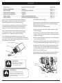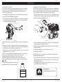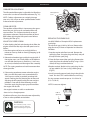
1
Operator’s Manual
®
4-Cycle
PROPANE POWERED TRIMMER
Models: 104.79212
104.79211
16.4 oz. / 465 g propane bottle
not included
• SAFETY
• ASSEMBLY
• OPERATION
• MAINTENANCE
• TROUBLESHOOTING
• WARRANTY
For assistance with assembly
or operation call:
1-800-235-5878
CAUTION: Before using
this product, read this
manual and follow all
safety rules and operating
instructions.
Sears, Roebuck and Co., Hoffman Estates, IL 60179, U.S.A.
Visit our web site: www.sears.com/craftsman
769-03546
SERVICE AND SAFETY
CRAFTSMAN
WARNING:
4-CYCLE PROPANE TRIMMER
When using this unit, you must follow these
safety rules. Please read these to ensure
the safety of the operator and any bystanders.
Please keep these instructions for later use.
TABLE OF CONTENTS
Service and Safety ..................................................................... 2
Safe Operation Rules ................................................................. 3
Understanding your trimmer................................................... 4
Assembly ....................................................................................... 5
Oil Information.............................................................................. 6
Understanding Propane........................................................... 7
Installing the Propane Canister.............................................. 8
Installing Attachments............................................................... 9
Starting / Stopping ..................................................................... 10
Operation....................................................................................... 11
Maintenance ................................................................................ 12
Cleaning and Storage ............................................................... 17
Troubleshooting........................................................................... 17
Specifications .............................................................................. 18
Warranty ......................................................................................... 19
IMPORTANT SAFETY INSRUCTIONS
READ ALL INSTRUCTIONS BEFORE OPERATING
• Inspect the unit before use. Replace damaged parts.
• Check for fuel leaks. Make sure all fasteners are in place
and secure. Replace parts that are cracked, chipped,
or damaged in any way. Do not operate the unit with
loose or damaged parts.
• Carefully inspect the area before starting the unit.
Remove all debris and hard or sharp objects such as
glass, wire, etc.
SPARK ARRESTOR NOTE
• Be aware of the risk of injury to the head, hands and
feet.
NOTE:
For users on U.S. Forest Land and in the states of
California, Maine, Oregon, and Washington. All U.S.
Forest Land and the state of California (Public Resources
Codes 4442 and 4443), Oregon, and Washington require
by law that certain internal combustion engines operated
on forest brush and / or grass-covered areas be equipped
with a spark arrestor, maintained in effective working
order, or the engine be constructed, equipped and
maintained for the prevention of fire. Check with with
your state or local authorities for regulations pertaining
to these requirements. Failure to follow these requirements could subject you to liability or a fine. This unit is
is factory equipped with a spark arrestor.
• Clear the area of children, bystanders, and pets. At
a minimum, keep all children, bystanders, and pets
outside a 50 feet (15 m.) radius; there still may be a risk
to bystanders from thrown objects. Bystanders should
be encouraged to wear eye protection. If you are
approached, stop the unit immediately.
• Use only Craftsman red medium thickness (85908)
or black wide thickness (85909) replacement lines.
Never use metal reinforced line, wire or rope.
These can break off and become dangerous projectiles.
• Squeeze the throttle control and check that it returns
automatically to the idle position. Make all adjustments
or repairs before using unit.
All information, illustrations, and specifications in this
manual are based on the latest production information
available at the time of printing. We reserve the right to
make changes at any time without notice.
• Do not operate this unit when tired, ill, under the
influence of alcohol, drugs or medications.
• This unit is intended for adult use only. Do not allow
children or untrained individuals to use the unit.
WARNING:
• Familiarize yourself with the controls and proper use of
your trimmer prior to using.
When servicing, use only identical
replacement parts. Use of any other
parts may create a hazard or product
damage.
2
SAFE OPERATION RULES
• Never start or run the unit inside a closed room or building. Breathing exhaust fumes can be fatal. Operate this
unit only in a well ventilated outdoor area.
• Do not operate the engine faster than the speed needed
to cut, trim or edge. Do not run the engine at high speed
when not cutting.
• Wear safety glasses or goggles that meet ANSI Z87.1
standards and are marked as such. Wear ear/hearing
protection when operating this unit. Wear a face or dust
mask if the operation is dusty.
• Always stop the engine when cutting is delayed or when
walking from one cutting location to another.
• If you strike or become entangled with a foreign object,
stop the engine immediately and check for damage. Do
not operate before repairing damage. Do not operate
the unit with loose or damaged parts. Stop the unit,
switch the engine to off, and disconnect the spark plug
for maintenance or repair.
• Wear heavy long pants, boots, gloves and a long sleeve
shirt. Do not wear loose clothing, jewelry, short pants,
sandals or go barefoot. Secure hair above shoulder
level.
• The cutting attachment shield must always be in place
while operating the unit as a trimmer. Do not operate
unit without proper line installed.
• Use only identical replacement parts and accesories
designed for this line trimmer. Use of any other
parts or accessories could lead to serious injury
to the user, or damage to the unit, and void your
warranty
• This unit has a clutch. The cutting attachment remains
stationary when the engine is idling. If it does not, have
the unit adjusted by a Sears or other qualified service
dealer.
• Keep unit clean of vegetation and other materials. They
may become lodged between the cutting attachment
and shield.
• Adjust the handle to your size in order to provide the
best grip.
• To reduce fire hazard, replace a faulty muffler and spark
arrestor. Keep the engine and muffler free from grass,
leaves, excessive grease or carbon buildup.
• Be sure the cutting attachment is not in contact with
anything before starting the unit.
• Use the unit only in daylight or good artificial light.
OTHER SAFETY WARNINGS
• Avoid accidental starting. Be in the starting position
whenever pulling the starter rope. The operator and
unit must be in a stable position while starting. Refer to
Starting/Stopping Instructions (p.10).
• Never store a unit with propane canister attached inside
a building where vapor may reach an open flame or
spark.
• Allow the engine to cool before storing or transporting.
Be sure to secure the unit while transporting.
• Only use this tool for its intended purpose.
• Do not overreach. Always keep proper footing and bal ance.
• Always hold the unit with both hands when operating.
Keep a firm grip on both handles or grips.
• Store the unit in a dry area, locked up or up high to
prevent unauthorized use or damage, out of the reach
of children.
• Never douse or squirt the unit with water or any other
liquid. Keep handles dry, clean and free from debris.
Clean after each use, see Cleaning and Storage instructions. (p.19)
• Keep hands, face, and feet at a distance from all moving
parts. Do not touch or try to stop the cutting attachment
when it rotates.
• Do not touch the engine, gear housing or muffler. These
parts get extremely hot from operation, even after the
unit is turned off.
• Keep these instructions. Refer to them often and use
them to instruct other users. If you loan someone this
unit, also loan them these instructions.
WARNING:
The engine exhaust from this product
contains chemicals known to the state of
California to cause cancer, birth defects
or other reproductive harm.
SAVE THESE INSTRUCTIONS
3
UNDERSTANDING YOUR TRIMMER
SAFETY & INTERNATIONAL SYMBOLS
This operator’s manual describes safety and international symbols and pictographs that may appear on this product.
Read the operator’s manual for complete safety, assembly, operating and maintenance and repair information.
I
WARNING: Indicates danger, warning or caution.
May be used in conjunction with other symbols or
pictographs.
o
WARNING: READ OPERATOR’S MANUAL:
Read the operator’s manual(s) and follow all warnings
and safety instructions. Failure to do so can result in
serious injury to the operator and/or bystanders.
WEAR EYE AND HEARING PROTECTION WARNING:
Thrown objects and loud noise can cause severe eye
injury and hearing loss. Wear eye protection meeting
ANSI Z87.1 standards and ear protection when
operating this unit. Use a full face shield when needed.
ON / OFF STOP CONTROL ON / START / RUN
ON / OFF STOP CONTROL OFF or STOP
KEEP BYSTANDERS AWAY WARNING:
Keep all bystanders, especially children and pets, at
least 50 feet (15 m) from the operating area.
OIL : Refer to operator’s manual for the proper type of oil.
HOT SURFACE WARNING:
Do not touch a hot muffler, gear housing or cylinder. You
may get burned. These parts get extremely hot from operation. They remain hot for a short time after the unit turned off.
THROWN OBJECTS AND ROTATING CUTTER CAN
CAUSE SEVERE INJURY WARNING:
Do not operate without the cutting attachment shield in
place. Keep away from the rotating cutting attachment.
SHARP BLADE WARNING:
Sharp blade on cutting attachment shield. To prevent
serious injury, do not touch the line cutting blade.
Muffler Guard
Fast Idle
Lock
On / Off
Control
Safety
Trigger
Starter Rope
Grip
Spark Plug
Cover
Upper Handle
Hassle Free™
Cutting Head
Air Filter
Cover
Attachment
Shaft
Shaft Grip
Throttle
Control
Attachment
Coupler
Propane Canister
Anti-Kickback
Bar
This illustration may differ from your unit.
For example, the picture shows a straight
shaft; your unit may have a curved shaft.
4
ASSEMBLY
TOOL KIT
FOR STRAIGHT SHAFT TRIMMERS
Your unit is provided with a tool kit (Fig.1). This tool kit
consists of the following:
Place the cutting attachment shield onto the shaft
mount. Install using provided hardware in the sequence
as shown (Fig.3).
4 mm Allen Wrench
Shaft Mount
5 mm Allen Wrench
8 & 10 mm Wrench
Four 5 mm Screws
with captive washers
Cutting Attachment Shield
Four Washers
Plate Washer
Washer
Lock Washer
Straight Shaft models
include 2 Plate Washers
Attaching Screws
Fig. 3
Phillips Screw Driver/
Socket Wrench
INSTALLING THE UPPER HANDLE AND SAFETY BAR
1. Locate the 4 screws included in the tool kit.
2. Assemble the upper handle, safety bar and 4 attaching
screws as shown in (Fig.4). Position the handle parts
evenly over the rubber sleeve on shaft. Do not completely tighten.
Fig. 1
INSTALLING CUTTING ATTACHMENT SHIELD
Use the following instructions if the cutting attachment
shield on your unit is not installed. Use only the
instructions that apply to the type of shaft and shield
that your unit is equipped with.
3. While holding the unit in the operating position (Fig.
14), position the upper handle to the location that provides you the best grip.
4. Tighten the clamp screws evenly, until the upper handle
is secure.
FOR CURVED SHAFT TRIMMERS
Place the cutting attachment shield and spacer against
tube as shown in (Fig.2). Use the 2 screws provided
to clamp the cap and shield onto the tube. Tighten the
screws evenly. Make sure the shield does not touch
any rotating parts.
Attaching
Screws
Upper Handle
Cutting Attachment Shield
Rubber Sleeve
Spacer
Safety Bar
Cap
Fig. 4
WARNING:
To prevent serious injury, never operate the
trimmer without the cutting attachment
in place.
Washer
Attaching Screws
Fig. 2
5
OIL INFORMATION
RECOMENDED OIL TYPE
2. Place the unit on a level surface (Fig. 6).
Using the proper type and weight of oil in the crankcase
is extremely important. Check the oil before each use
and change the oil regularly. Failure to use the correct oil,
or using dirty oil, can cause premature engine wear and
failure. Use a high-quality SAE 10W-30 weight oil of API
(American Petroleum Institute) service class SF, SG, SH.
ADDING OIL TO THE CRANKCASE
:
INITIAL USE
NOTE: This unit is shipped without oil in the crankcase.
In order to avoid damage to the unit, put oil in the
crankcase before you attempt to start the unit.
Your unit is supplied with one 2.5 fluid oz. (75 mL) bottle
of SAE 10W- 30 SF, SG or SH oil (Fig. 5).
Fig. 6
3. Remove the oil plug / dipstick from the crankcase (Fig.7).
1. Unscrew the top of the bottle of oil and remove the
paper seal covering the opening. Replace the top.
(Fig. 5).
4. Pour the entire bottle of oil into the oil fill hole (Fig.7).
4-Cycle Motor Oil
Oil fill plug/dipstick
Fig. 5
Oil Fill Hole
Fig. 7
NOTE: Save the bottle of oil. It can be used to measure
the correct amount during future oil changes. See
Changing The Oil (p.13).
Check oil before each use and change as needed. Refer
to Changing the Oil (p.13).
5. Wipe up any oil that may have spilled and reinstall
the oil plug/dipstick.
WARNING:
Overfilling crankcase may cause hot oil to drip
from air filter, and smoke to come out from the
exhaust. Check and maintain the proper oil
level in the crank case; it is important and
cannot be over emphasized. Check the oil
before each use and change as needed.
See Changing the Oil (p.13).
6
UNDERSTANDING PROPANE
SAFETY WARNINGS FOR PROPANE UNITS
NOTE: FIRE/EXPLOSION HAZARD
NOTE: Use propane only in containers specifically
designed and approved for this unit. Propane is a
combustible gas; it is colorless and thus invisible to the
naked eye. Propane has a harmless odorant added so
that it is possible to smell it. The propane odorant
makes the propane smell like sulfer or rotten eggs.
If at any time the smell of propane is identified,
turn off the engine. If the leak persists, remove the pro pane canister. Never attempt to operate a unit that has
a suspected leak. Always remove the propane canister
from any unit that has a suspected leak.
Contains enough gas to cause serious fire, explosion,
and burns. To reduce chance of leak, fire, or explosion:
BEFORE USE
1. Check propane cylinder and trimmer seals. Never use
with damaged or missing seals. Discard cylinder if dirt
or rust particles are in valve area.
2. Turn trimmer off.
3. Attach cylinder outdoors away from pilot lights, flames,
sparks or other ignition sources. These sources can
ignite leaking gas.
4. Hand tighten only. Never use tools to tighten. Overtightening can damage seals.
5. Check for leaks. Put soapy water on connections.
Look for bubbles. Listen for hiss of escaping gas. Feel
for extreme cold. Smell for rotten egg odor. Do not
use if leaking.
6. Read and follow trimmer instructions.
CARBON MONOXIDE HAZARD
Burning propane makes Carbon Monoxide (CO). CO is
invisible, has no smell and can kill you. Operating your
trimmer in an enclosed area can be dangerous.
1. Use only in well ventilated areas. If you experience
headache, drowsiness, or nausea, turn unit off and
get fresh air quickly.
2. Never use where people are sleeping.
3. Follow unit instructions for proper use.
DURING USE
Never use near pilot lights, flames, sparks, or other
ignition sources. They can ignite leaking gas.
HANDLING & STORAGE
1. Keep out of reach of children.
2. Never expose cylinder to heat, sparks, or flame.
Never leave in direct sunlight. Never store at tem peratures above 120 degrees (49 degrees C).
3. Never store in living spaces.
4. Always use cylinder until it is completely empty.
5. Never refill a disposable cylinder. Refilling may cause
an explosion. Federal law forbids transportation if re filled, imposes a penalty up to $500,000, and 5 years
imprisonment (49 U.S.C. 5124).
6. Never put in luggage or take on trains or aircraft.
7. To discard, contact local refuse hauler or recycle center.
Never put in fire or incinerator. Do not puncture. If
your cylinder was purchased with a “Green Key” * or
similar device, install it when empty and cylinder may
be recycled with other steel items.
AFTER USE
1. Turn trimmer off and let cool.
2. Detach cylinder when not in use.
3. Detach outdoors away from pilot lights, flames, sparks,
or other ignition sources; they can ignite leaking gas.
4. Replace cylinder cap to keep valve clean.
IN CASE OF FIRE
1. Leave area quickly and call 911 or your local fire department for help.
2. Let fire burn out.
* Green Key- is a trademark of the Coleman company
7
INSTALLING THE PROPANE CANISTER
WARNING:
Propane is highly flamable, and its vapors
can explode if ignited.
Take the following precautions.
Propane
Connector
USE THE CORRECT PROPANE CANISTER
Always use Propane canisters or “Bottles” that are the
correct size. The 17 ounce or 16.4 ounce canisters that
are approximately 3-7/8 inch in diameter are the cor rect canisters (Fig.8). Do not use the smaller diameter
canisters as they will not latch securely to the unit and
vibration may cause damage to the trimmer and potentially result in a dangerous leak.
Fig. 8
Fig. 9B
REMOVING THE PROPANE CANISTER
1. Make sure the engine is off.
2. Un-latch the bottle clamp and push canister against the
guard exposing the propnae connector. Remove the
propane connector by turning it counterclockwise.
16.4 OZ. / 465 g
CANISTER
3. Remove the empty canister.
4. Dispose of empty propane canisters in accordance
to Federal, State and local Regulations.
ATTACHING THE PROPANE CANISTER
1. Make sure the engine is off.
WARNING:
2. If the propane canister to be installed has a protective plastic cap over the threaded end, remove it.
Make sure the canister clamp is in the un-latched
position.
Never attempt to force a connector onto
a propane canister that has improper or
damaged threads.
3. Insert the threaded end of the propane canister into
the clamp as far as it will go (Fig. 9A). Insert the propane connector onto the threaded end of the canister and screw it
onto threads clockwise (Fig. 9B). Screw it until snug.
Do not over tighten. It may be normal to hear or smell
a slight momentary leak of propane as the connector
is being screwed in. Make sure that the connector is
installed tight enough that any leakage stops. Hand
tight is sufficient. Slide canister back so all of fuel line
components are behind the guard and latch the canister
clamp.
WARNING:
This container and by-products of
the combustion of its contents contain
chemicals known to the state of
California to cause cancer, birth
deffects, or other reproductive harm.
WARNING:
Extrememly flamable fire/explosion.
Hazard contents under pressure.
Carbon monoxide hazard.
WARNING:
Guard
Propane is extremely flamable. Vapor
may explode. Always stop the engine
and allow it to cool before replacing
the propane canister. Do not smoke.
Keep sparks and open flames at a
distance from the area.
Canister
Clamp
Fig. 9A
8
INSTALLING ATTACHMENTS
AVAILABLE CUTTING ATTACHMENTS
EDGING POSITION
Brushcutter attachment..................................................358.79244
Edger attachment..............................................................358.79240
Cultivator attachment......................................................358.79241
Blower attachment............................................................358.79242
Pruner attachment.............................................................358.79245
For edging, lock the release button of the cutting
attachment into the 90° edging hole (Fig.11), so that the
engine remains in the upright position while operating.
90° Edging
Hole
INSTALLING CUTTING ATTACHMENTS
Your unit is provided with the Hassle-Free™ Cutting
Head attachment shaft.
NOTE: Place the unit on the ground or on a work bench
to make accessory installation or removal easier.
Fig. 11
1. Turn knob counterclockwise to loosen (Fig.10).
REMOVING CUTTING ATTACHMENTS
2. While firmly holding the attachment shaft, push it straight
into the attachment coupler (Fig.10).
1. Turn the knob counterclockwise to loosen (Fig.12).
NOTE: Aligning the release button with receiving hole will
help installation (Fig.10).
Attachment
Coupler
2. Press and hold the release button (Fig.12).
3. While firmly holding the upper shaft housing, pull
the cutting attachment or add-on straight out of the
coupler (Fig.12).
Line up parts
Receiving Hole
Release Button
Coupler
Release Button
Upper Shaft
Housing
Attachment
Shaft
Knob
Fig. 10
Fig. 12
3. Turn the knob clockwise to tighten (Fig. 11). The unit is
ready to use.
WARNING:
NOTE:
To avoid serious injury and damage to the unit,
shut off the unit before removing or installing
attachments.
• Lock the release button in the receiving hole and
securely tighten the knob before operating this unit.
• Except for edging, attachments are to be used in the
receiving hole only. Using the wrong hole could lead
to personal injury or damage to the unit.
• Always install the attachment so that the engine is
upright (propane tank on bottom) when unit is operated. A secondary receiving hole is provided for use of
a trimmer being used for edging only. No other accessory should be used in this secondary hole (90° edging
hole) ( Fig.11).
9
STARTING / STOPPING
STARTING INSTRUCTIONS
Start/On(I)
1. Check the oil level in the crankcase. Refer to Checking
the Oil Level ( p.12).
Stop/Off
Fast Idle
Lock
2. Turn switch to ON position (Fig.14).
Safety trigger
NOTE: If your unit is equipped with a spring loaded type
ON/OFF switch, it will always remain in the ON position.
3. Place trimmer firmly on the ground or a very sturdy
work surface. Make sure cutting head is clear of all
objects. Make sure all bystanders are a minimum of
50 feet (15m) away. Do not attempt to start near pilot
lights or any open flame. Do not smoke. Grasp the
starter rope handle with one hand and the handle
pole with the other hand ( Fig.13).
Throttle Control
Fig. 14
NOTE: When starting the engine in very hot or cold
conditions it may be necessary to squeeze the throttle
control while pulling the starter rope.
STOPPING INSTRUCTIONS
1. Release your hand from the throttle control. Allow the
engine to cool down by idling.
2. If your unit is equipped with a spring loaded ON/
OFF switch, press and hold the button on OFF until
the unit stops. Otherwise, push the switch to the off
position.
3. When done using the trimmer for the day, disconnect
the propane canister from the unit.
WARNING:
Fig. 13
Avoid accidental starting. Make sure you are in the starting
position when pulling the starter rope (Fig. 13). To avoid
serious injury, the operator and unit must be in a stable
position while starting. Make sure that any add-on item is
installed correctly and secure before starting the unit.
4. With the unit in the starting position, do not squeeze
the throttle control (Fig.14). Then pull the rope
smoothly and briskly. The engine should start. A cold
engine should start with 3-5 pulls. A warm engine
should start on the first pull.
NOTE: On the very first use, it may take extra pulls to fill
the fuel system with propane.
WARNING:
Always wear eye, hearing, foot and body
protection to reduce the risk of injury when
operating this unit.
5. Squeeze the throttle control slightly to warm up the
engine for 15 to 30 seconds. In cold weather, move
the throttle slowly until the engine warms up for 30 to
60 seconds.
NOTE: This unit is provided with a Fast Idle Lock (Fig. 14). If
experiencing starting difficulties under regular conditions,
squeeze the throttle control, then push and hold the Fast
Idle lock forward while releasing the throttle trigger. Then
start the unit.
10
OPERATION
OPERATING YOUR TRIMMER
• Trim only when grass and weeds are dry.
Before operating the unit, stand in the operating position
(Fig. 15). Check for the following:
• The life of your cutting line is dependent upon:
• The operator is wearing eye protection and proper
clothing.
2. What vegetation is cut
1. Proper adherence to explained trimming techniques
3. Where vegetation is cut
• With a slightly bent right arm, the operator’s right
hand is holding the shaft grip.
• The operator’s left arm is straight, and left hand holding
the upper handle.
For example, the line will wear faster when trimming
against a foundation wall as opposed to trimming
around a tree.
• The unit is at waist level.
Some line breakage will occur from:
• The cutting attachment is parallel to the ground and
easily contacts the grass without the need to bend over.
• Entanglement with foreign matter
• Normal line fatigue
HOLDING THE TRIMMER
• Attempting to cut thick, stalky weeds
• Forcing the line into objects such as walls or fence posts
NOTE: This unit is equipped with an Anti-Kickback bar.
This bar helps protect you from “kick-back” which may
occur during operation. The Anti-Kickback bar hits the
side of your leg when the trimmer jumps back, preventing the cutting head to contact the operator.
Fig. 15
TIPS FOR BEST TRIMMING RESULTS
• For best trimming results, operate unit at full throttle.
• Keep the cutting attachment parallel to the ground.
• Do not force the cutting attachment. Allow the tip
of the line to do the cutting, especially along walls.
Cutting with more than the tip will reduce cutting
efficiency and may overload the engine.
• Cut grass over 8 inches (200 mm) by cutting from top
to bottom in small increments to avoid premature line
wear or engine drag.
• Slowly move the trimmer into and out of the cutting
area at the desired height. Move either in a forwardbackward or side-to-side motion. Cutting shorter
lengths produces the best results.
11
MAINTENANCE
FREQUENCY
MAINTENANCE REQUIRED
REFER TO
BEFORE STARTING ENGINE
CHECK OIL
PAGE 6
EVERY 10 HOURS
CLEAN AND RE-OIL AIR FILTER
PAGE 13
FIRST CHANGE AT 10 HOURS
CHECK OIL
PAGE 13
EVERY 25 HOURS THEREAFTER
CHECK OIL
PAGE 13
EVERY 25 HOURS
CHECK SPARK PLUG POSITION GAP
PAGE 14
EVERY 25 HOURS
ROCKER ARM CLEARANCE ADJUSTMENT
PAGE 16
CHECKING THE OIL LEVEL
Perform these required maintenance procedures at
the frequency stated in the table. These procedures
should also be a part of any seasonal tune-up.
The importance of checking and maintaining the proper
oil level in the crankcase cannot be overemphasized.
Check oil before each use:
NOTE: Failure to maintain your trimmer at the recommended schedule may result in poor performance
and/or cause permanent damage to your trimmer
1. Stop the engine and allow to cool.
2. Place the unit on a flat, level surface to get a proper
oil level reading.
NOTE: Some maintenance procedures may require
special tools or skills. If you are unsure about these
procedures call 1-800-235-5878 for assistance.
3. Keep dirt, grass clippings and other debris out of the
engine. Clean the area around the oil fill plug/dipstick
before removing it.
NOTE: Maintenance, replacement, or repair of the
emission control devices and system may be performed
by any non-road engine repair establishment, individual
or authorized service dealer.
4. Remove the oil fill plug/dipstick and wipe off oil. Reinsert it all the way back in.
5. Remove the oil fill plug/dipstick and check the oil level.
Oil should be between the add and fill marks (Fig. 16).
Oil Fill Plug/Dipstick
6. If the level is low, add a small amount of oil to the oil
fill hole (Fig.17) and recheck. Repeat this procedure
until the oil level reaches the full mark of the dipstick.
O-ring
NOTE: Do not overfill the unit.
Full
NOTE: Make sure the O-Ring is in place on the oil fill plug/
dipstick when checking and changing the oil (Fig. 16).
Add
Fig. 16
WARNING:
When servicing, use only identical
replacement parts. Use of any
other parts may create a hazard
or cause product damage.
Oil Fill Plug/
Dipstick
WARNING:
To prevent extensive engine wear and
damage to the unit, always maintain the
proper oil level in the crankcase. Never
operate the unit with the level below the
bottom of the dipstick.
Oil Fill Hole
Fig. 17
12
MAINTENANCE
CHANGING THE OIL
CLEANING THE AIR FILTER
For a new engine, change the oil after the first 10 hours
of operation. Change the oil while the engine is still
warm but not hot. The oil will flow freely and carry
away more impurities.
Clean and re-oil the air filter every 10 hours of operation.
It is an important item to maintain. Failure to maintain
your air filter properly can result in poor performance or
can cause permanent damage to your engine.
1. Unplug spark plug wire to prevent accidental starting.
1. Remove the phillips head screw in the air filter cover.
Then pull the air filter cover out and upwards (Fig.20) .
2. Remove the oil fill plug/dipstick.
2. Remove the air filter (Fig. 20).
3. Pour the oil out of the oil fill hole and into a container
by tipping the unit to its side (Fig. 18). Allow ample
time for complete drainage.
Air Filter
Air Filter
Cover
Screw
Air Filter
Base Plate
Fig. 18
Fig. 20
NOTE: Wear gloves to prevent injury when handling the
unit.
3. Wash the filter in detergent and water. Rinse the filter
thoroughly and allow it to dry.
4. Wipe up any oil residue on the unit and clean up any
oil that may have spilled. Dispose of the oil according
to Federal, State and local regulations.
4. Apply enough clean SAE 10W-30 motor oil to lightly
coat the filter.
5. Squeeze the filter and remove excess oil.
5. Refill the crankcase with 2.5 fluid oz. (75 mL) of SAE
10W-30 SF, SG, or SH oil.
6. Replace the filter.
NOTE: Use the bottle saved from initial use to measure
the correct amount of oil. The bottle measures
approximately 2.5 fluid oz. (75 mL) (Fig. 16).
Check the level with the dipstick. If the level is low,
add a small amount of oil and recheck. Do not overfill
NOTE: If the unit is operated without the air filter, you
will VOID the warranty.
7. Reinstall the air filter cover. Position the hooks on the
top of the air filter base plate into the slots at the top
of the filter cover.
6. Replace the oil fill plug/dipstick.
8. Swing the cover until the air filter cover snaps into
place and replace the screw.
7. Reconnect the spark plug boot.
WARNING:
To avoid serious personal injury, be sure
to turn the unit off before servicing it.
4-Cycle Motor Oil
Fig. 19
13
MAINTENANCE
CARBURETOR ADJUSTMENT
The idle speed of the engine is adjustable. An idle adjustment screw is on the rear side of the carburetor (Fig. 21).
Idle Adjustment
Screw
NOTE: Careless adjustments can seriously damage
your unit. Only a Sears or other qualified dealer should
make carburetor adjustments.
CLEAN AIR FILTER
The condition of the air filter is important to the operation of the unit. A dirty or oil saturated air filter will
restrict air flow. This is often mistaken for an out of
adjustment carburetor. Check the condition of the air
filter before adjusting the idle speed screw. Refer to
Cleaning Air Filter (p.13).
Fig.21
REPLACING THE SPARK PLUG
Use NGK CMR6A or Champion RCJ6Y replacement
spark plugs.
The correct air gap is 0.02 in. (0.5 mm). Remove the
plug after every 25 hours of operation and check its
condition.
ADJUST IDLE SPEED SCREW
If, after checking the fuel and cleaning the air filter, the
engine still will not idle, adjust the idle speed screw as
follows:
1.Start the engine and let it run at a high idle for a
minute to warm up. Refer to Starting/Stopping (p.10)
instructions.
1.Stop the engine and allow it to cool. Remove the
spark plug cover. Grasp the plug wire firmly and pull
the cap from the spark plug.
2. Release the throttle trigger and let the engine idle. If
the engine stops, use a small phillips or flat blade to
turn the idle speed screw in, clockwise, 1/8 of a turn
at a time (as needed) until the engine idles smoothly.
2.Clean dirt from around the spark plug. Remove the
spark plug from the cylinder head by using a 5/8 in.
socket, turning it counterclockwise.
NOTE: The cutting attachment should not rotate when
the engine idles.
3.Replace cracked, fouled or dirty spark plug. Set the
air gap at 0.02 in. (0.5 mm.) using a feeler gauge
(Fig 22).
3. If the cutting attachment rotates when the engine
idles, turn the idle speed screw counterclockwise
1/8 of a turn at a time (as needed), to reduce idle
speed. Checking the fuel, cleaning the air filter, and
adjusting the idle speed should solve most engine
problems. If not and all of the following are true,
check the spark plug for proper gap and condition.
4.Install a correctly-gapped spark plug in the cylinder
head. Turn the 5/8 in. socket clockwise until snug.
If using a torque wrench torque to: 110-120 in. lb.
(12.3-13.5 N-m)
NOTE: Do not over tighten.
• the engine will not idle
• the engine hesitates or stalls on acceleration
0.02 in.
(0.5 mm)
• there is a loss of engine power
If problem still occurs, have the carburetor adjusted by
a Sears or other qualified service dealer.
WARNING:
Do not sand blast, scrape, or clean
spark plug electrodes. Grit in the
engine could damage the cylinder.
Fig.22
14
MAINTENANCE
3. Pull the ends of the line until the line bend is centered
between the two insertion holes and firmly against the
side of the cutting head (Fig. 25).
LINE REPLACEMENT
For Hassle-Free™ Cutting Head
Always use Craftsman Hassle Free XTRA QUIET Spiral
Line. Choose the line size best suited for the job at
hand. Red colored line is designed for cutting grass
and small weeds. Black colored line is designed for
cutting larger weeds and light brush.
NOTE: Before inserting new line into the holes in the
cutting head, identify the proper holes by following
the directions on the glide plate (Fig. 23). Do not
attempt to remove the cutting head from the unit
when replacing line.
Fig. 25
1. Insert both ends of your line into the insertion
holes in the side of the cutting head (Fig. 23).
4. Correctly installed line will be the same length on both
sides.
NOTE: Some line breakage will occur from:
Trimming
Line
• Entanglement with foreign matter
• Normal line fatigue
• Attempting to cut thick, stalky weeds
Insertion
Holes
Positioning
Tunnel
• Forcing the line into objects such as walls or fence post
Glide Plate
Fig. 23
2. Push the bend in the line until the ends of the line
push through the positioning tunnels (Fig. 24).
Fig. 24
15
MAINTENANCE
8. Pull the starter rope slowly to bring the piston to
the top of its travel, (this position is known as top
dead center).Check that the piston is at the top of
its travel by looking down into the spark plug hole.
Both valves should be closed and the rocker arms
should move freely. If this statement is not true,
repeat this step until top dead center is acheived
before proceeding to the next step.
ROCKER ARM CLEARANCE ADJUSTMENT
1. Remove the four screws on the engine cover with a
phillips head screw driver (Fig. 26).
2. Remove the engine cover.
3. Disconnect the spark plug wire.
4. Clean dirt from around the spark plug. Remove the
spark plug by using tool provided, turn counterclockwise. This requires partial dissasembly of the engine.
If you feel unsure or unqualified to perform this,
take the unit to a Sears or other qualified service dealer.
9. Slide a feeler gage between the rocker arm and the
valve return spring. Measure the distance between
the rocker arm and valve stem (Fig. 28) Take care
to only measure the free play. It is very easy to
insert too thick a feeler gauge and accidentally
depress the valve and valve return spring. Measure
both the intake and exhaust valve distances.
NOTE: Inspect the valve to rocker arm clearance with a
feeler gage after the first 25 hours of operation. The
engine must be cold when checking or adjusting the
valve clearances. This task should be performed in a
clean dust free environment.
Adjusting Screws
Rocker Arm
Jam Nuts
Feeler Gauge
Engine cover
screws
Exhaust Valve
Engine cover
screws
Intake Valve
Valve Return
Spring
Fig. 26
Fig. 28
5. Clean dirt from around the rocker arm cover.
6. Remove the three screws holding the rocker arm
cover with a phillips head screwdriver.
7. Remove the rocker arm cover and gasket (Fig. 27).
10. Check the spark plug and reinstall, see Replacing
the Spark Plug (p.14).
11. Reinstall the spark plug wire.
IF THE CLEARANCE IS NOT WITHIN SPECIFICATION
Rocker Arm Cover
Screws
1. Loosen the jam nut and turn the adjusting screw
as necessary. To increase the clearance, turn the
adjusting screw counterclockwise. To decrease
the clearance, turn the adjusting screw clockwise.
2. Tighten the jam nut when the clearance is set.
Rocker Arm
Cover
3. Recheck the both clearances. Readjust if necessary.
4. Reinstall the rocker arm cover using a new gasket.
5. Tighten cover screws evenly until snug.
Fig. 27
6. Reinstall the engine cover checking the alignment of
the cover. Tighten the four engine cover screws until
snug.
WARNING:
To prevent serious injury, never perform maintenance
or repairs with unit running. Always service and repair
a cool unit. Disconnect the spark plug wire to ensure
that the unit cannot start.
• The recommended clearance for both intake and
exhaust is 0.076-0.152mm (0.003-0.006in).
• Use a standard automotive 0.127mm (0.005in) feeler gage.
16
CLEANING AND STORAGE
CLEANING
LONG TERM STORAGE
Use a small brush to clean the outside of the unit. Do
not use strong detergents. Household cleaners that
contain aromatic oils such as pine and lemon, and sol vents such as kerosene, can damage plastic housing or
handle. Wipe off any moisture with soft cloth.
1. Remove propane canister.
STORAGE
NOTE: Remove the spark plug and drain all of the oil
from the cylinder before attempting to start the trimmer
after storage.
2. Allow the engine to cool. Remove the spark plug and
put 5 drops of high quality motor oil into the cylinder.
Pull the starter rope slowly to distribute the oil. Rein stall the spark plug.
• Remove propane canister.
• Never store the unit with attached propane canister where
fumes may reach an open flame or spark.
• Allow the engine to cool before storing.
• Lock up the unit to prevent unauthorized use or damage.
• Store the unit in a dry, well-ventilated area.
• Store unit out of reach of children.
3. Change the oil, referring to Changing the Oil (p.13).
Dispose of the old oil in accordance to Federal, State
and Local regulations.
4. Thoroughly clean the unit and inspect for any loose
or damaged parts. Repair or replace damaged parts
and tighten loose screws, nuts or bolts. The unit is
ready for storage.
WARNING:
To avoid serious injury, always turn
your off and allow it to cool before
you service it.
TRANSPORTATION
• Allow the engine to cool before transporting.
• Secure the unit while transporting.
• Remove propane canister.
TROUBLESHOOTING
ENGINE WILL NOT START
CAUSE
ACTION
Empty propane canister
Install full canister
Bad spark plug
Replace the spark plug
ENGINE WILL NOT IDLE
CAUSE
ACTION
Air filter is plugged
Replace or clean the air filter
Improper carburetor adjustment
Adjust according to the carburetor
adjustment section or take to a Sears or
other qualified service dealer for an adjustment
ENGINE WILL NOT ACCELERATE
CAUSE
ACTION
Cutting attachment bound with grass
Stop the engine & clean the cutting attachment
Dirty air filter
ENGINE LACKS POWER OR STALLS WHEN CUTTING
Clean or replace the air filter
CAUSE
ACTION
Bad spark plug
Replace the spark plug
IF FURTHER ASSISTANCE IS REQUIRED, CONTACT A SEARS OR OTHER QUALIFIED SERVICE DEALER.
17
SPECIFICATIONS
ENGINE*
ENGINE TYPE
AIR-COOLED 4-CYCLE
DISPLACEMENT
25.4 CC
CLUTCH TYPE
CENTRIFUGAL
OPERATING R.P.M.
6,800-9,300 R.P.M.
IDLE SPEED
3,000-3,400 R.P.M.
IGNITION TYPE
ELECTRONIC
IGNITION SWITCH
PUSH ON/ OFF SWITCH
VALVE CLEARANCE
0.003-0.006 INCHES (0.076-0.152 mm)
SPARK PLUG GAP
0.02 INCHES (0.5 mm)
LUBRICATION
SAE 10W-30 OIL
CRANKCASE OIL CAPACITY
2.5 FLUID OZ. (75 mL)
FUEL
PROPANE 16 OZ. / 465 G CANISTER
CARBURETOR
CHOKE-LESS, ALL POSITION
STARTER
PULL START WITH AUTO REWIND
MUFFLER
BAFFLED WITH GUARD
THROTTLE
SAFETY LOCK WITH MANUAL SPRING RETURN
DRIVE SHAFT AND HOUSING
DRIVE SHAFT HOUSING
ALUMINUM TUBE
THROTTLE CONTROL
FINGER-TIP TRIGGER
APPROXIMATE UNIT WEIGHT
13.1-14.9 LBS
CUTTING MECHANISM
HASSLE FREE ™ CUTTING HEAD
CUTTING HEAD DIAMETER
4-1/4 INCHES (108 mm)
TRIMMING LINE
RED MEDIUM (71-85908) OR BLACK LARGE (71-85909)
CUTTING PATH DIAMETER
14 INCHES (356 mm)
*ALL SPECIFICATIONS ARE BASED ON THE LATEST PRODUCT INFORMATION AT THE TIME OF PRINTING.
WE RESERVE THE RIGHT TO MAKE CHANGES AT ANY TIME WITHOUT NOTICE.
18
WARRANTY STATEMENT
CRAFTSMAN FULL WARRANTY
If this Craftsman product fails due to a defect in material or workmanship within two years from the date of purchase, return it to any Sears store,
Parts and Repair Service Center, or other Craftsman outlet in the United States for free repair (or replacement if repair prove s impossible).
This warranty applies for only 90 days if this product is ever used for commercial or rental purposes.
This warranty covers ONLY defects in materal and workmanship. Sears will NOT pay for:
•
Expendable items that can wear out from normal use within the warranty period, such as cutting line, filters or spark plugs.
•
Repairs necessary because of accident or failure to operate or maintain the product according to all supplied instructions.
•
Preventive maintenance, or repairs necessary due to improper fuel mixture, contaminated or stale fuel.
This warranty gives you specific legal rights, and you may also have other rights which vary from state to state.
Sears, Roebuck and Co., Hoffman Estates, IL 60179
Repair Protection Agreements
Congratulations on making a smart purchase. Your new Craftsman® product is designed and manufactured for years of dependable
operation. But like all products, it may require repair from time to time. That’s when having a Repair Protection Agreement can save you
money and aggravation.
Here’s what the Repair Protection Agreement* includes:
Expert service by our 10,000 professional repair specialists
Unlimited service and no charge for parts and labor on all covered repairs
Product replacement up to $1500 if your covered product can’t be fixed
Discount of 10% from regular price of service and related installed parts not covered by the agreement; also, 10% off regular price of
preventive maintenance check
Fast help by phone – we call it Rapid Resolution – phone support from a Sears representative. Think of us as a “talking owner’s manual.”
Once you purchase the Repair Protection Agreement, a simple phone call is all that it takes for you to schedule service. You can call anytime
day or night, or schedule a service appointment online.
The Repair Protection Agreement is a risk-free purchase. If you cancel for any reason during the product warranty period, we will provide a
full refund. Or, a prorated refund any time after the product warranty period expires. Purchase your Repair Protection Agreement today!
Some limitations and exclusions apply. For prices and additional information in the U.S.A. call 1-800-827-6655.
*Coverage in Canada varies on some items. For full details call Sears Canada at 1-800-361-6665.
Sears Installation Service
For Sears professional installation of home appliances, garage door openers, water heaters, and other major home items, in the U.S.A. or
Canada call 1-800-4-MY-HOME ® .
19
Get it fixed, at your home or ours!
Your Home
For expert troubleshooting and home solutions advice:
www.managemyhome.com
For repair – in your home – of all major brand appliances,
lawn and garden equipment, or heating and cooling systems,
no matter who made it, no matter who sold it!
For the replacement parts, accessories and
owner’s manuals that you need to do-it-yourself.
For Sears professional installation of home appliances
and items like garage door openers and water heaters.
1-800-4-MY-HOME®
(1-800-469-4663)
Call anytime, day or night (U.S.A. and Canada)
www.sears.com
www.sears.ca
Our Home
For repair of carry-in items like vacuums, lawn equipment,
and electronics, call anytime for the location of your nearest
Sears Parts & Repair Service Center
1-800-488-1222 (U.S.A.)
www.sears.com
1-800-469-4663 (Canada)
www.sears.ca
To purchase a protection agreement on a product serviced by Sears:
1-800-827-6655 (U.S.A.)
1-800-361-6665 (Canada)
Para pedir servicio de reparación
a domicilio, y para ordenar piezas:
Au Canada pour service en français:
1-888-SU-HOGAR®
1-800-LE-FOYER MC
(1-888-784-6427)
® Registered Trademark / TM Trademark / SM Service Mark of Sears Brands, LLC
® Marca Registrada / TM Marca de Fábrica / SM Marca de Servicio de Sears Brands, LLC
MC
Marque de commerce / MD Marque déposée de Sears Brands, LLC
(1-800-533-6937)
www.sears.ca
© Sears Brands, LLC