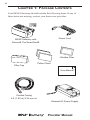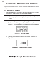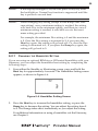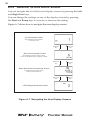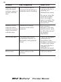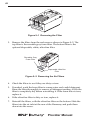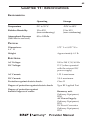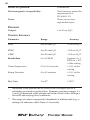
1
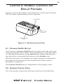
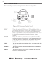
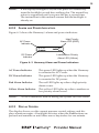
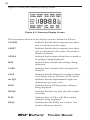
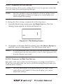
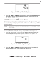
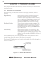
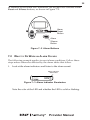
www.respironics.com
User Manual
BiPAP systems are the subject of one or more patents: U.S. Patents
#5148802, #5239995, #531937, #5433193; Canadian Patent #2, 024,477;
European Patent #EP0425092; German Patent #6902161681.5-08; and
other pending U.S. and foreign patents. BiPAP, Harmony, Encore and
SmartCard are registered trademarks of Respironics, Inc.
© 2003 Respironics, Inc. All rights reserved.
2
TABLE OF CONTENTS
CHAPTER 1: PACKAGE CONTENTS ........................................................................... 4
CHAPTER 2: WARNINGS AND CAUTIONS ................................................................. 5
2.1 WARNINGS ................................................................................................ 5
2.2 CAUTIONS ................................................................................................. 6
2.3 INTENDED USE .......................................................................................... 6
2.4 CONTRAINDICATIONS ................................................................................. 7
2.5 PRECAUTIONS ............................................................................................ 7
2.6 INDUSTRY CANADA NOTICE ....................................................................... 8
CHAPTER 3: INTRODUCTION TO THE HARMONY ....................................................... 9
3.1 DEFINITIONS .............................................................................................. 9
3.2 WHAT IS THE HARMONY? ........................................................................ 10
3.2 WHAT IS THE HARMONY? ........................................................................ 11
3.3 SYMBOLS ................................................................................................. 12
3.4 HOW TO CONTACT RESPIRONICS .............................................................. 12
CHAPTER 4: HARMONY CONTROLS AND
DISPLAY FEATURES ........................................................................................ 13
4.1 PRESSURE ON/OFF BUTTON .................................................................... 13
4.2 HARMONY CONTROL PANEL ................................................................... 13
4.2.1 CONTROL KEYS ............................................................................. 14
4.2.2 ALARM AND POWER INDICATORS ................................................... 15
4.2.3 DISPLAY SCREEN ........................................................................... 15
4.2.4 BREATHING CIRCUIT CONNECTION ................................................ 18
4.2.5 REAR PANEL ................................................................................. 18
CHAPTER 5: SETTING UP THE HARMONY ............................................................... 20
5.1 INSTALLING THE AIR FILTERS ................................................................... 20
5.2 WHERE TO PLACE THE HARMONY ........................................................... 21
5.3 CONNECTING THE BREATHING CIRCUIT .................................................... 21
5.4 COMPLETE HARMONY SETUP ................................................................... 23
5.5 PLUGGING THE HARMONY IN .................................................................. 24
5.5.1 USING AC POWER ........................................................................ 24
5.5.2 USING DC POWER ........................................................................ 24
CHAPTER 6: OPERATING THE HARMONY .............................................................. 26
6.1 STARTING THE HARMONY ........................................................................ 26
6.2 CHANGING THE DEVICE SETTINGS ........................................................... 28
6.2.1 CHANGING THE HUMIDIFIER SETTING ............................................ 29
6.2.2 NAVIGATING THE USER DISPLAY SCREENS ...................................... 30
6.2.2.1 CHANGING THE FLEX SETTING ............................................ 31
6.2.2.2 CHANGING THE RISE TIME SETTING .................................... 31
6.2.2.3 CHANGING THE RAMP STARTING PRESSURE ......................... 32
6.2.2.4 CHANGING THE LED BACKLIGHT SETTING ......................... 33
Provider Manual
3
CHAPTER 7: HARMONY ALARMS ........................................................................... 34
7.1 INTRODUCTION TO ALARMS ..................................................................... 34
7.2 WHAT TO DO WHEN AN ALARM OCCURS ............................................... 35
7.3 ALARM TABLES ....................................................................................... 37
7.3.2 MEDIUM PRIORITY ALARMS ........................................................... 38
7.3.3 LOW PRIORITY ALARMS ................................................................. 38
CHAPTER 8: TROUBLESHOOTING ............................................................................ 39
CHAPTER 9: CLEANING AND MAINTENANCE ........................................................ 41
9.1 CLEANING THE HARMONY ....................................................................... 41
9.2 CLEANING OR REPLACING THE INLET FILTERS .......................................... 41
CHAPTER 10: ACCESSORIES .................................................................................. 44
10.1 ADDING A HUMIDIFIER .......................................................................... 44
10.2 ADDING OXYGEN TO THE HARMONY ..................................................... 44
CHAPTER 11: SPECIFICATIONS ............................................................................... 45
ENVIRONMENTAL ........................................................................................... 45
PHYSICAL ...................................................................................................... 45
ELECTRICAL ................................................................................................... 45
PRESSURE ...................................................................................................... 46
CONTROL ACCURACY .................................................................................... 46
INDEX ................................................................................................................... 47
Provider Manual
4
CHAPTER 1: PACKAGE CONTENTS
Your BiPAP Harmony should include the following items. If any of
these items are missing, contact your home care provider.
Power Cord
BiPAP Harmony with
Encore® Pro SmartCard®
Ultrafine Filter
Filter Cap
Pollen Filters
www.respironics.com
User Manual
Flexible Tubing
6 ft. (1.83 m) X 22 mm i.d.
External AC Power Supply
Provider Manual
5
CHAPTER 2: WARNINGS AND CAUTIONS
WARNING:
Indicates the possibility of injury to the user or operator.
CAUTION:
Indicates the possibility of damage to the device.
NOTE:
Places emphasis on an operating characteristic.
2.1 WARNINGS
•
This manual serves as a reference. The instructions in this
manual are not intended to supersede the instructions of your
health care provider.
•
You should read and understand this entire manual before using
the Harmony.
•
The Harmony is not intended to provide your total ventilatory
requirement.
•
The prescription must only be adjusted by a trained home care
provider.
•
Use only the breathing circuit provided by your home care
provider.
•
When using a breathing circuit that contains a mask with an
integrated exhalation port or a circuit with a separate exhalation
device, do not tape, seal, or otherwise block the vent openings.
Doing so could result in suffocation.
If oxygen is used with the Harmony, the oxygen flow must be
turned off when the Harmony is not in use.
Oxygen supports combustion. Oxygen should not be used while
smoking or in the presence of an open flame.
•
•
•
Do not use the Harmony in the presence of flammable liquids or
gases. Do not clean the Harmony with flammable fluids.
•
Do not use the Harmony if the room temperature is above 95º F
(35°C). If the device is used at room temperatures above 95° F,
the temperature of the airflow may exceed 106º F (41°C), which
could cause irritation to your airway.
•
Do not operate the Harmony in direct sunlight or near a heating
appliance because these conditions can increase the temperature
of the air coming out of the Harmony.
•
When the Harmony is used with a humidifier, position the
humidifier so that the water level in the humidifier is lower than
you and the humidifier is on the same level or lower than the
Harmony.
Provider Manual
6
•
If you detect any unexplained changes in the performance of the
Harmony, if the device is dropped or mishandled, or if the
enclosure is broken, seek the assistance of your home care
provider.
•
If water is spilled into the enclosure, discontinue use of the
Harmony and remove the power cord. Pour out the excess liquid
and allow the unit to dry out. If the device does not function
properly, contact your home care provider.
•
Repairs and adjustments must be performed by Respironics authorized service personnel only. Unauthorized service could
cause injury, invalidate the warranty, or result in costly damage.
•
Periodically inspect electrical cords for damage or signs of wear.
•
To avoid electrical shock, unplug the Harmony before cleaning
it.
2.2 CAUTIONS
CAUTION!
US federal law restricts this device to sale by or on the
order of a physician.
•
The Harmony may only be operated at temperatures between
41º F (5°C) and 95º F (35°C).
•
A properly installed, undamaged reusable foam inlet filter is
required for proper operation.
•
Do not immerse the Harmony or allow any liquid to enter the
enclosure or the inlet filter.
•
Condensation may damage the Harmony. Always allow the
Harmony to reach room temperature before use.
Additional warnings, cautions, and notes are located throughout
this manual.
2.3 INTENDED USE
The Harmony is intended to provide noninvasive ventilation in adult
patients (>30 kg) for the treatment of respiratory insufficiency (a condition in which the patient can continue without ventilation for some
period of time, such as overnight) or obstructive sleep apnea. This
device may be used in the hospital or home.
The Harmony is intended for use with nasal masks and full-face masks
as recommended by Respironics.
Provider Manual
7
2.4 CONTRAINDICATIONS
The Harmony should not be used if you have severe respiratory failure
without a spontaneous respiratory drive.
If any of the following conditions apply to you, consult your physician
before using the Harmony:
•
Inability to maintain a patent airway or adequately clear
secretions
•
•
•
At risk for aspiration of gastric contents
•
•
Epistaxis, causing pulmonary aspiration of blood
Diagnosed with acute sinusitis or otitis media
Allergy or hypersensitive to the mask materials where the risk
from allergic reaction outweighs the benefit of ventilatory
assistance
Hypotension
2.5 PRECAUTIONS
•
Immediately report any unusual chest discomfort, shortness of
breath, or severe headache.
•
If skin irritation or breakdown develops from the use of the
mask, refer to the mask instructions for appropriate action.
•
The following are potential side effects of noninvasive positive
pressure therapy:
— Ear discomfort
— Conjunctivitis
— Skin abrasions due to noninvasive interfaces
— Gastric distention (aerophagia)
Provider Manual
8
2.6 INDUSTRY CANADA NOTICE
NOTICE: The Industry Canada Label identifies certified equipment.
This certification means that the equipment meets telecommunications
network protective, operational, and safety requirements as prescribed
in the appropriate Terminal Equipment Technical Requirements documents. The Department does not guarantee the equipment will operate
to the user’s satisfaction.
Before installing this equipment, users should make sure that it is
permissible to be connected to the facilities of the local telecommunications company. The equipment must also be installed using an acceptable method of connection. The customer should be aware that compliance with the above conditions may not prevent degradation of service
in some situations.
Repairs to certified equipment should be coordinated by a representative designated by the supplier. Any repairs or alterations made by the
user to this equipment, or equipment malfunctions, may give the
telecommunications company cause to request the user to disconnect
the equipment.
Users should ensure for their own protection that the electrical ground
connections of the power utility, telephone lines and internal metallic
water pipe system, if present, are connected together. The precaution
may be particularly important in rural areas.
CAUTION:
Users should not attempt to make such connections
themselves, but should contact the appropriate electric
inspection authority, or electrician, as appropriate.
Ringer Equivalence Number (REN): The REN assigned to each terminal device provides an indication of the maximum number of terminals
allowed to be connected to a telephone interface. The termination on an
interface may consist of any combination of devices subject only to the
requirement that the sum of the Ringer Equivalence Numbers of all the
devices does not exceed 5.
Provider Manual
9
CHAPTER 3: INTRODUCTION TO THE HARMONY
This chapter contains the following information:
•
Definitions for common terms used throughout this manual
•
An overview of the Harmony device
•
An explanation of the symbols used on the Harmony and
throughout this manual
•
Contact information
3.1 DEFINITIONS
The following terms appear throughout this manual:
Apnea
A condition marked by the cessation of
spontaneous breathing.
CPAP
Continuous Positive Airway Pressure
EPAP
Expiratory Positive Airway Pressure
High Priority Alarm
Alarm signal indicating a condition that
requires immediate attention
IPAP
Inspiratory Positive Airway Pressure
Low Priority Alarm
Signal indicating an information message
Medium Priority Alarm
Alarm signal indicating a condition that
requires operator awareness
Operate State
The state of the Harmony device when the
unit and the blower are both on.
Standby State
The state of the Harmony device when the
unit is on, but the blower is off.
OSA
Obstructive Sleep Apnea
Patient Disconnect Alarm This event occurs when the device detects a
larger circuit leak. The event terminates when
the circuit leak returns to normal limits or
when initiated by the user.
Ramp
A feature that may increase patient comfort
when therapy is started. The Harmony IPAP
starts at the EPAP level and is increased
gradually (breath by breath over several
breaths) until the IPAP prescription pressure
is reached.
Provider Manual
10
Rise Time
The time it takes for the Harmony to change
from EPAP to IPAP. You can adjust this time
for your comfort.
RR
Respiratory Rate
Spontaneous (S)
A bi-level mode which responds to both your
inhalation and exhalation by increasing
pressure when you start to inhale and decreasing pressure when you start to exhale.
There is no automatic delivery of a breath
should you not inhale.
Spontaneous/
Timed (S/T)
A bi-level mode which responds to both your
inhalation and exhalation by increasing
pressure when you start to inhale and decreasing pressure when you start to exhale. If
you do not start inhaling within a set time, the
Harmony automatically starts inhalation.
When the Harmony starts inhalation, it
controls the time of inhalation and automatically decreases the pressure for exhalation
within a set time.
3.2 WHAT IS THE HARMONY?
The Harmony, shown in Figure 3–1, supplies air pressure through a
breathing ciruit.
Figure 3–1 The Harmony
Provider Manual
11
The circuit, shown in Figure 3–2, consists of:
•
Circuit tubing to deliver air from the Harmony to your interface
(e.g., mask)
•
A mask or other interface to deliver the prescribed pressure to
your nose or nose and mouth, depending on which interface has
been prescribed for you
•
An exhalation port to vent exhaled air from the circuit
Patient Interface
(Typical)
Exhalation Ports
(one port on each
side of elbow)
Exhalation Device
(Typical)
Circuit
Tubing
Circuit with Separate
Exhalation Device
Circuit with Mask with
Integrated Exhalation Ports
Figure 3–2 Typical Breathing Circuits
NOTE:
The exhalation port may be part of the mask or may be part of
a separate exhalation device.
The system senses your breathing effort and changes pressure levels
when you inhale and exhale depending on the mode of operation.
The Harmony can operate on AC or DC power. The DC power option is
not intended as a battery backup. When DC power is obtained from a
vehicle battery, the Harmony should not be used while the vehicle’s
engine is running.
Provider Manual
12
3.3 SYMBOLS
The symbols shown below are used on the Harmony and throughout
this manual.
Symbol
Meaning
Attention, consult accompanying documents
DC Power
Type BF Applied Part
Class II (Double Insulated)
European CE Declaration of Conformity
Notified Body Approval
for Standards Compliance
Canadian/US Certification
3.4 HOW TO CONTACT RESPIRONICS
To have your unit serviced, contact your home care provider. If you
need to contact Respironics directly, call 1-800-345-6443 or use the
following address:
Provider Manual
13
CHAPTER 4: HARMONY CONTROLS AND
DISPLAY FEATURES
Figure 4–1 shows the location of the Harmony’s control panel, Pressure
On/Off button, and breathing circuit connection.
Control Panel
Breathing Circuit
Connection
Pressure On/Off
Button
Figure 4–1 Harmony Front and Top
4.1 PRESSURE ON/OFF BUTTON
The Harmony’s Pressure On/Off button, located on the side of the unit,
starts and stops the unit’s airflow. Press the button in to turn the airflow
on. This puts the Harmony in the Operate state. Depress the button to
turn the airflow off and put the Harmony in the Standby state.
When the Harmony is in Standby, any ramp in progress is terminated,
the alarms are reset (except for the System Errors alarm), and the
humidifier is turned off.
The Pressure On/Off button is independent of the display screen.
4.2 HARMONY CONTROL PANEL
The control panel contains the following control keys and indicators.
Provider Manual
14
4.2.1 CONTROL KEYS
The control keys on the control panel are shown in Figure 4–2.
Display
Screen
RESET
HEAT
Alarm
Reset
Button
RAMP
Heated
Humidifier
Button
SILENCE
User
Buttons
Ramp
Button
Alarm
Silence
Button
Figure 4–2 Harmony Control Panel
HEAT
When the optional REMstar or H2 heated humidifier is
prescribed, this button controls the humidifier’s output.
Follow the instructions provided with the humidifier.
When a humidifier is not in use, this button can be used
to adjust the parameters shown in the user menu
screens.
RAMP
When the airflow is turned on, this button lowers the
airflow pressure, allowing you to fall asleep more easily.
When the airflow is turned off, this button can be used
to adjust the parameters shown in the user menu
screens.
USER
The left and right user buttons allow you to navigate the
display screens.
SILENCE
This button silences the audible portion of an alarm for
one minute.
RESET
This button allows you to clear an alarm and reset the
device for alarm detection.
Provider Manual
15
NOTE:
If the display backlight is off, the first press of a control key
turns the backlight on and does nothing else. The normal key
action is suppressed until you press the key a second time.
The instructions in this manual assume that the backlight is
already on.
4.2.2 ALARM AND POWER INDICATORS
Figure 4–3 shows the Harmony’s alarm and power indicators.
High Priority
Alarm LED (RED)
AC Power
Indicator
AC Power
ALARMS
DC Power
DC Power
Indicator
Low/Medium Priority
Alarm LED (Yellow)
Figure 4–3 Harmony Alarm and Power Indicators
AC Power Indicator
This green LED lights up when the Harmony
is connected to AC Power.
DC Power Indicator
This green LED lights up when the Harmony
is connected to DC power.
Red Alarm Indicator
The red LED lights up when a high priority
alarm occurs.
Yellow Alarm Indicator
This yellow LED lights up when a medium or
low priority alarm occurs.
NOTE:
All LED indicators turn on during the System Self Test screen.
4.2.3 DISPLAY SCREEN
The display shows you the current pressure control settings and displays alarm messages. A backlight activates when the User buttons are
pressed and remains on until there are no keystrokes for one minute.
Provider Manual
16
Figure 4–4 shows the Harmony display screen.
Figure 4–4 Harmony Display Screen
The information shown on the display screen is defined as follows:
ALARM
Indicates that the device requires user attention as indicated on the screen.
ALERT
Indicates that the device requires user attention as indicated on the screen. Not used for
Harmony devices.
APNEA
Indicates that an apnea alarm has occurred or
its setting is being displayed.
BPM
Indicates that a breath rate setting is being
displayed.
CARD
Indicates that a SmartCard is inserted and
detected.
CPAP
Indicates that the Harmony is in the Continuous Positive Airway Pressure (CPAP) mode.
cm H2O
Indicates that the alphanumeric digits are
displaying a pressure valve.
EPAP
Indicates that an EPAP pressure setting is
being displayed.
ERASE
Indicates that the user may clear the compliance data.
FLEX
Indicates that a C-Flex or Bi-Flex comfort
setting is being displayed.
FOSQ
Indicates that the FOSQ test is active. Not
used for Harmony devices.
Provider Manual
17
HEAT
Indicates that the humidifier is turned on
and/or its setting is displayed.
HOURS
Indicates that the Therapy Hour Meter is
being displayed.
INSP. TIME
Indicates that the inspiratory time setting is
being displayed.
IPAP
Indicates that an IPAP pressure setting is
being displayed.
LIGHT
Indicates that the keypad LED backlight
setting is being displayed or is active.
NIGHTS
Indicates that the session counter is being
displayed. Not used for Harmony devices.
PATIENT
Indicates that a Patient Disconnect alarm is
active or its setting is being displayed.
PC
Indicates the Pressure Control mode. Not
used for Harmony devices.
RAMP
Indicates that the Ramp function is in
progress, or during Provider mode, that the
Ramp length is being displayed.
RAMP START
Indicates that the Ramp Starting Pressure is
being displayed.
RATE
Used in conjunction with the BPM.
RISE TIME
Indicates that a rise time setting is being
displayed.
S
Indicates that the alphanumeric digits are
displaying a time value.
SETUP
Indicates that the device is in Provider mode
and not in User or Diagnostic mode.
S/T
Indicates that the Harmony is in the Spontaneous mode if only the S appears, or the
Spontaneous/Timed mode if the S/T appears.
Provider Manual
18
4.2.4 BREATHING CIRCUIT CONNECTION
Figure 4–5 shows where the circuit tubing connects to the Harmony.
Patient Interface
(Typical)
Exhalation Port
(Typical)
Circuit
Tubing
Bacteria
Filter
(Optional)
Patient
Interface
Port
Figure 4–5 Breathing Circuit Connection
4.2.5 REAR PANEL
Figure 4–6 shows the Harmony’s rear panel.
Communications Port
DC Inlet
SmartCard
Connector
Filter Cap
Figure 4–6 Rear Panel
NOTE:
The SmartCard Connector is located on the side of the Harmony.
Provider Manual
19
The rear panel contains the following:
RS-232 Communications
Connector
This connector accepts the Respironics
Communications cable for computer and
external modem communication.
DC Inlets
There are two DC inlets on the rear panel,
one for connecting the external AC power
supply and another for battery operation
using an external DC power supply.
Filter Cap
The filter cap can be removed to inspect the
inlet air filters.
Provider Manual
20
CHAPTER 5: SETTING UP THE HARMONY
This chapter provides instructions on how to:
•
Install the air filters
•
Position the Harmony unit
•
Connect the breathing circuit
•
Plug the Harmony in using AC or DC power
5.1 INSTALLING THE AIR FILTERS
CAUTION:
A properly installed, undamaged foam filter is required
for proper operation.
The Harmony uses a gray foam filter that is washable and reusable, and
an optional white, ultra-fine filter that is disposable. One filter of each
kind is supplied with the Harmony.
If your home care provider did not install the inlet air filters, you must
install at least the gray foam filter before using the Harmony.
1.
Place the gray foam filter on top of the ultra-fine filter (if using the
ultra-fine filter).
2.
Slide the filters into the air inlet at the rear of the Harmony, and push
them down into the recess as shown in Figure 5-1.
Reusable Gray
Foam Filter
Filter
Cap
Disposable Ultra-fine
Filter
Figure 5–1 Installing the Filters
3.
Attach the filter cap as shown in Figure 5–2. Position the cap so that
the small opening on the cap is facing down. Insert the caps bottom
tabs into the openings below the filter area. Snap the cap into place.
Provider Manual
21
Figure 5–2 Attaching the Filter Cap
NOTE:
The filter cap should be installed with the air inlet opening at
the bottom.
See Chapter 8 to clean or replace the filters.
5.2 WHERE TO PLACE THE HARMONY
Place the Harmony on its base somewhere within easy reach of where
you will use it. Make sure that the air inlet on the rear of the unit is not
blocked. Place the unit on a hard, flat surface. If you block the air flow
around the unit, the Harmony may not work properly.
If you are using a humidifier, place the humidifier and unit on a
placemat or other waterproof material to protect your furniture from
moisture. Position the humidifier so the water level is lower than you
and the humidifier is on the same level or lower than the Harmony. See
the humidifier instructions for complete setup information.
5.3 CONNECTING THE BREATHING CIRCUIT
To connect your breathing circuit to the Harmony, complete the following steps:
1.
Connect one end of the circuit tubing to the outlet of the bacteria
filter (if using one) and connect the inlet of the bacteria filter to the
large connector on the Harmony as shown in Figure 5–3.
If you are not using a bacteria filter, connect the end of the circuit
tubing directly to the outlet connector on the Harmony.
Provider Manual
22
NOTE:
Follow the recommendations of your home care provider for
using the optional bacteria filter.
Circuit
Tubing
Bacteria
Filter
(Optional)
Figure 5–3 Connecting the Tubing to the Outlet
2.
Connect the open end of the circuit tubing to the exhalation port as
shown in Figure 5–4. If you are using a mask that has the exhalation
port built into the mask, connect the tubing directly to the mask and
skip to Step 4.
Exhalation
Port
Circuit
Tubing
Figure 5–4 Connecting the Tubing to the Exhalation Port
WARNING: The exhalation device or exhalation port is designed to
exhaust CO2 from the patient circuit. Do not block or seal
the ports on the exhalation device.
Provider Manual
23
3.
Connect the exhalation port to the mask connector as shown in
Figure 5–5.
Mask or Other
Interface
Mask Connector
Exhalation Port
Figure 5–5 Connecting the Mask
4.
Attach the headgear to the mask. See the instructions that came with
your headgear.
5.4 COMPLETE HARMONY SETUP
Figure 5–6 shows the completed breathing circuit setup for the Harmony.
Patient Interface
(Typical)
Exhalation Port
(Typical)
Circuit
Tubing
Bacteria
Filter
(Optional)
Figure 5–6 Complete Harmony Breathing Circuit
Provider Manual
24
5.5 PLUGGING THE HARMONY IN
You can use AC power or DC power to operate the Harmony.
WARNING: The DC power option is not intended as a battery backup
when using AC power.
5.5.1 USING AC POWER
Complete the following steps to operate the Harmony using AC power:
1.
Plug the pronged end of the AC power supply’s cord into an electrical outlet.
WARNING: Never plug the Harmony AC power supply into an outlet
that is controlled by a wall switch.
2.
Leaving a small amount of slack in the cord, connect the cord on the
other side of the power supply to the AC inlet on the Harmony, as
shown in Figure 5–7.
NOTE:
The external AC power supply features an AC cord retainer to
provide strain relief for the AC power cord.
Figure 5–7 Plugging in the AC Power Supply
5.5.2 USING DC POWER
Complete the following steps to operate the Harmony using DC power:
CAUTION:
Only use a Respironics-supplied DC boost converter.
Provider Manual
25
1.
Plug the DC boost converter into the rear of the Harmony, as shown
in Figure 5–8.
2.
Leaving a small amount of slack in the cord, press the cord into the
DC cord retainer.
3.
Connect the DC cord to the appropriate DC source. See the instructions that came with the DC boost converter for proper DC connections.
CAUTION:
When DC power is obtained from a vehicle battery, the
Harmony should not be used while the vehicle’s engine is
running. Damage to the vehicle may occur.
DC Power Source
Figure 5–8 Plugging in the DC Boost Converter
Provider Manual
26
CHAPTER 6: OPERATING THE HARMONY
This chapter explains how to start the Harmony and change the device
settings.
6.1 STARTING THE HARMONY
1.
Plug the Harmony in to power up the unit. The Harmony sounds a
confirmation alarm and the keypad buttons light up.
NOTE:
If the alarm does not sound or the buttons do not light up, the
Harmony requires servicing. Contact your home care provider.
Several screens appear initially during this step:
a.
The first screen that appears is the Self Test screen, shown in
Figure 6–1. This is the internal test performed by the Harmony.
Figure 6–1 Self Test Screen
b. The next screen displays the software version, as shown in
Figure 6–2:
Figure 6–2 Software Version Screen
Provider Manual
27
c.
The third screen to appear is the Blower Hours screen, which
displays the blower hours time meter:
Figure 6–3 Blower Hours Screen
NOTE:
With the exception of the Pressure On/Off button, the keypad
is inactive during these first three screens. Each of these first
three screens appears for approximately 1-3 seconds.
d. The next screen that appears is the Standby screen, shown in
Figure 6–4. This indicates that the Harmony is in the Standby
state.
Figure 6–4 Standby Screen
2.
Press the Pressure On/Off button to put the unit into the Operate
state. The Monitoring screen, shown in Figure 6–5, appears.
Figure 6–5 Monitoring Screen
The Monitoring screen displays the actual measured pressure along
with the appropriate icons.
Provider Manual
28
3.
Put on your mask assembly when the air starts to flow.
4.
Make sure that no air is leaking from your mask into your eyes. If it
is, adjust the mask and headgear until air stops leaking into your
eyes. See the instructions that came with your mask for more information.
5.
If you are using the Harmony while sleeping, try placing the tubing
from the Harmony over your headboard. This may reduce tension
on the mask.
NOTE:
6.
A small amount of mask leak is normal and acceptable.
Correct large mask leaks or eye irritation from an air leak as
soon as possible.
Relax. Take normal, relaxed breaths through your nose.
NOTE:
If you are having trouble with your mask, see Chapter 7,
Troubleshooting, for some suggestions.
6.2 CHANGING THE DEVICE SETTINGS
You can view the following settings on the Harmony display screen:
•
Measured pressure
•
Mode
•
SmartCard
•
Breath Rate
•
Patient alarms
Additionally, you can view and modify the following settings using the
display screens:
•
Humidifier
•
Flex
•
Rise Time
•
Ramp start pressure
•
LED backlight
Provider Manual
29
NOTE:
If the display backlight is off, the first press of any key turns
the backlight on. Normal key function is suppressed until the
key is pressed a second time.
NOTE:
When changing any setting (except for the Ramp Start Pressure setting), once a maximum setting is reached, the setting
rolls back over to the minimum setting, and likewise, once a
minimum setting is reached, it rolls back over to the maximum setting provided.
For example, the minimum Flex setting is 1 and the maximum
is 3. Once the Flex setting is increased to 3, if you press the
Heat key again, the setting will go back at 1. Or, once the Flex
setting is decreased to 1, if you press the Ramp key again, the
setting will go back to 3.
6.2.1 CHANGING THE HUMIDIFIER SETTING
If you are using an optional REMstar or H2 heated humidifier with your
Harmony, you can adjust the humidifier heat setting by completing the
following steps:
1.
From either the Standby or Monitoring screen, press and hold the
Heat key for approximately 4 seconds. The Humidifier Setting screen
appears, as shown in Figure 6–6.
Figure 6–6 Humidifier Setting Screen
2.
Press the Heat key to increase the humidifier setting, or press the
Ramp key to decrease the setting. You can adjust the setting from 1
to 5. The change takes effect immediately as you adjust the setting.
For additional information on using a humidifier wit the Harmony,
see Chapter 9.
Provider Manual
30
6.2.2 NAVIGATING THE USER DISPLAY SCREENS
You can navigate the rest of the user display screens by pressing the Left
and Right User keys.
You can change the settings on any of the display screens by pressing
the Heat and Ramp keys to increase or decrease the setting.
Figure 6–7 shows how to navigate the user display screens.
Flex Parameter Screen
Only displayed if the Flex setting
is not equal to zero.
Right User
Key
Left User
Key
Right User
Key
Left User
Key
Right User
Key
Left User
Key
Rise Time Parameter Screen
Only displayed if the Flex setting is equal
to zero and the Mode setting is NOT set to CPAP.
Ramp Start Pressure Parameter Screen
Only displayed if the Ramp Length
setting is greater than zero.
LED Backlight Parameter Screen
Figure 6–7 Navigating the User Display Screens
Provider Manual
31
6.2.2.1 CHANGING THE FLEX SETTING
The Flex setting allows you to adjust the level of air pressure relief that
you feel when you exhale during therapy.
NOTE:
The Flex feature is not prescribed for all users. If the screen
shown in Figure 6–8 does not appear on your display, you
cannot adjust this setting.
To change the Flex setting, complete the following steps:
1.
From the Monitoring screen, press the Right User key. The Flex
Setting screen appears, as shown in Figure 6–8.
Figure 6–8 Flex Setting Screen
2.
To increase or decrease the Flex setting, press the Heat or Ramp key
until the correct setting appears. You can choose from 1 to 3.
NOTE:
It is recommended that you start with the minimum setting of
1, which provides the least relief. Levels 2 and 3 progressively
increase the pressure relief.
6.2.2.2 CHANGING THE RISE TIME SETTING
Rise time is the time it takes for the Harmony to change from IPAP to
EPAP. You can adjust the rise time to find the setting that provides you
with the most comfort.
NOTE:
The rise time feature is not prescribed for all users. If the
screen shown in Figure 6–9 does not display, you cannot
adjust this setting.
Provider Manual
32
To change the rise time setting, complete the following steps:
1.
From the Monitoring screen, press the Right User key. The Rise Time
Setting screen appears, as shown in Figure 6–9.
Figure 6–9 Rise Time Setting Screen
2.
Increase or decrease the rise time setting from 1 to 6 by pressing the
Heat or Ramp key until you find the right setting. A setting of 1 is
the fastest rise time, while 6 is the slowest.
NOTE:
When the Harmony is in Bi-Flex mode, it will use a rise time
of 3 regardless of the chosen setting.
6.2.2.3 CHANGING THE RAMP STARTING PRESSURE
The Harmony is equipped with an optional ramp feature that your
home care provider can turn on or off. This feature will reduce the
pressure and then gradually increase (ramp) the pressure to the prescription pressure setting so you can fall asleep more comfortably.
NOTE:
The ramp feature is not prescribed for all users. If the screen
shown in Figure 6–10 does not appear on your display, you
cannot adjust this setting.
If your physician prescribed ramp for you, complete the following steps:
1.
From the Monitoring screen, press the Right User key until the
Ramp Start Setting screen appears, as shown in Figure 6–10.
Provider Manual
33
Figure 6–10 Ramp Start Setting Screen
2.
Press the Heat or Ramp key to increase or decrease the ramp starting
pressure as needed. You can adjust the setting from 4.0 cm H2O to
the EPAP or CPAP setting.
6.2.2.4 CHANGING THE LED BACKLIGHT SETTING
When airflow is turned on and the Harmony is in the Operate state, you
can turn the keypad lighting behind the buttons on or off using the LED
backlight setting.
NOTE:
The lights are always on when the airflow is off and the unit is
in Standby.
To change the LED backlight setting, complete the following steps:
1.
From the Monitoring screen, press the Right User button until the
LED Backlight Setting screen appears, as shown in Figure 6–11.
Figure 6–11 LED Backlight Setting Screen
2.
Press the Heat or Ramp key to select a new setting. A setting of 1
means the light is on, while 0 means the light is off.
Provider Manual
34
CHAPTER 7: HARMONY ALARMS
This chapter describes the Harmony alarms and what you should do if
an alarm occurs.
7.1 INTRODUCTION TO ALARMS
The Harmony provides three alarm levels: high, medium, and low
priority.
High Priority
These alarms require immediate response.
The alarm signal consists of a red LED
indicator and a sound that is either continuous or a pattern of three beeps, a pause, and
then two more beeps. The display has the
message ALARM at the top of the screen.
Medium Priority
These alarms require prompt response. The
alarm signal consists of a yellow LED and a
sound that repeats a pattern of three beeps.
The display has the message ALARM at the
top of the screen.
Low Priority
These alarms require your awareness. The
alarm signal consists of a yellow LED and a
sound that repeats a pattern of two beeps. The
display has the message ALARM at the top of
the screen.
Some audible alarms are self-cancellable. This means that the alarm
sound stops when the cause of the alarm is corrected.
The alarm LED indicators are located on the right side of the keypad, as
shown in Figure 7–1.
High Priority
Alarm LED (RED)
AC Power
ALARMS
DC Power
Low/Medium Priority
Alarm LED (Yellow)
Figure 7–1 Alarm LED Indicators
Provider Manual
35
In addition to the alarm LED indicators, the keypad also contains alarm
Reset and Silence buttons, as shown in Figure 7–2.
Alarm
Reset
Button
RESET
HEAT
RAMP
SILENCE
Alarm
Silence
Button
Figure 7–2 Alarm Buttons
7.2 WHAT TO DO WHEN AN ALARM OCCURS
The following example applies to most alarm conditions. Follow these
steps unless otherwise directed by the alarm tables that follow.
1.
Look at the alarm indicators and listen to the alarm sound.
Alarm Indicator
Illuminates
AC Power
ALARMS
DC Power
Figure 7–3 Alarm Indicator Illuminates
Note the color of the LED and whether the LED is solid or flashing.
Provider Manual
36
2.
Look at the display for text.
Figure 7–4 Sample Alarm Display
The word ALARM appears at the top of the screen to indicate an
alarm. Additional codes and icons may also appear depending on
the type of alarm.
3.
Press the Silence key to temporarily silence the alarm (for one
minute).
4.
Look up the alarm in the alarm tables in Section 7.3 and perform the
action specified.
5.
Press the Reset key to clear the alarm.
The alarm is cleared and the display returns to the screen that was
showing at the time of the alarm.
Provider Manual
37
7.3 ALARM TABLES
The following tables summarize the high priority, medium priority, and
low priority alarms.
Alarm
LED
Alarm
Sound
Display
Message
Harmony
Action
Possible
Cause
Red Flash
••• ••
ALARM and
PATIENT
words
flash
Operates
Breathing circuit is
disconnected or has
a large leak.
Reconnect the circuit
or fix the leak.
Red Flash
••• ••
ALARM
and APNEA
words flash
Operates
An apnea event
occurred during
therapy.
Report the alarm to
your home care
provider.
Red Flash
••• ••
ALARM
flashes and
an error
code
displays
Shuts down.
Blower cannot
be restarted.
Harmony failure
Cannot be silenced.
Remove power from
the unit and contact
your home care
provider.
••• ••
ALARM
and
cmH2O
flash
Operates
Blank
screen
Shuts down
or
Red Flash
Red Solid
Excessive leak
or blockage;
malfunctioning unit.
Your
Action
Check for the
following: dirty inlet
filters, blocked air
intake, excessive leak
in the circuit. If the
alarm continues, call
your home care
provider.
Battery is discharged. Remove DC power
source from the unit,
-orreplace the battery,
restore power to the
unit; or seek a reliable
AC power source.
Power was lost
while the unit was
providing therapy.
Press the Pressure On/
Off button to silence
the alarm, turn off the
red LED, and restore
power.
Provider Manual
38
7.3.2 MEDIUM PRIORITY ALARMS
Alarm
LED
Yellow Flash
Alarm
Sound
Display
Message
Harmony
Action
•••
DC Power
LED
Flashes
Operates
Possible
Cause
Battery nearly
discharged.
Your
Action
Replace the battery.
7.3.3 LOW PRIORITY ALARMS
Alarm
LED
Alarm
Sound
Yellow Solid
••
Yellow Solid
••
Yellow Solid
••
Display
Message
CARD
flashes and
card error
code (Cxx)
displays
ALARM,
CARD, and
cmH2O
flash and
LCD light
is on
DC power
LED flashes
Blank screen
Harmony
Action
Operates
Possible
Cause
Your
Action
There is a problem
with the SmartCard
inserted in the
SmartCard
connectivity slot.
Remove the SmartCard
from the device and
contact your home
care provider.
Operates
The SmartCard
storage capacity
is reached.
Remove the SmartCard
from the device and
contact your home
care provider.
Operates
Harmony lost AC
power and is now
operating on DC
power.
Check AC power and
seek reliable power
source.
At start-up only,
alarm notifies you
that a battery is
being used
to provide power.
Provide AC power if
you do not want to use
a battery; otherwise,
no action needed.
Provider Manual
39
CHAPTER 8: TROUBLESHOOTING
This chapter describes problems that you may experience with your
Harmony or mask and presents possible solutions.
Problem
Why It Happened
What To Do
Does not operate
when you press
thePressure On/
Off button.
If the power LED is off,
no power at the outlet or
the Harmony is unplugged.
The air out of
the mask is
much warmer
than usual.
The inlet filters may
be dirty.
The mask feels
uncomfortable
to wear.
This could be due to
improper headgear
adjustment or improper
mask fitting.
Check the headgear
adjustment as
described in the
headgear instructions.
Contact your home
care provider for a
refitting or a
different size mask.
There is significant This could be due to
air leakage around improper headgear
the mask.
adjustment or improper
mask fitting.
Check the headgear
adjustment as
described in the
headgear instructions.
Contact your home
care provider for a
refitting or a
different size mask.
If the power LED is on,
problems in the Harmony.
The Harmony may be
operating in direct
sunlight or near a heater.
Check the outlet
power and verify
that the Harmony
is plugged in.
Clean or replace the
inlet air filters as
described in Chapter
9. If the Harmony is
in direct sunlight or
near a heater, move it.
If the problem
persists, contact your
home care provider.
Provider Manual
40
Problem
Why It Happened
What To Do
Redness occurs
when the mask
cushion comes in
contact with the
skin.
This could be due to
improper mask fitting or
improper mask cleaning.
Contact your home
care provider for a
refitting or a
different size mask.
Redness occurs
when the mask
cushion accessory
comes in contact
with the skin.
Irritation or allergic
reaction to the mask
material.
Use a barrier
between your skin
and the mask, such
as 3M’s Microfoam®
or Squibb’s
Duoderm®.
Sore or dry eyes.
The mask may not be
positioned correctly, or
the mask is not properly
fitted.
Check the headgear
adjustment as
described in the
headgear instructions.
Contact your home
care provider for a
refitting or a
different size mask.
Runny nose.
Nasal reaction to the
air flow.
Call your doctor.
Be sure to rinse the
mask thoroughly
after cleaning to
remove residue. See
the mask cleaning
instructions.
Provider Manual
41
CHAPTER 9: CLEANING AND MAINTENANCE
This chapter provides information on how to clean and maintain your
Harmony system.
9.1 CLEANING THE HARMONY
Before cleaning or performing any routine maintenance, always make
sure the Harmony is not operating and disconnect the Harmony from
the power source.
NOTE:
The following cleaning instructions are for the Harmony only.
To clean the accessories, refer to each accessory’s instruction
sheet.
CAUTION:
Do not immerse the Harmony or allow any liquid to enter
the enclosure, inlet filter, or any openings.
Clean the front panel and exterior of the enclosure as needed using a
cloth dampened with water and a mild detergent. Allow the Harmony
to dry completely before plugging in the power cord.
Gently wash the reusable circuit tubing in a solution of warm water and
a mild detergent. Rinse thoroughly and allow to air dry.
9.2 CLEANING OR REPLACING THE INLET FILTERS
The Harmony has two removable filters at the air inlet. The gray foam
filter is washable and reusable. The optional white, ultra-fine filter is
disposable.
NOTE:
Dirty inlet filters may cause high operating temperatures and
may affect Harmony performance. Regularly examine the inlet
filters as needed for integrity and cleanliness.
1.
Make sure the Harmony is not operating, and disconnect the power
cord from the wall outlet.
2.
As shown in Figure 9–1, remove the filter cap by gently pressing
down on the top panel and pulling the cap out from Harmony’s
body.
Provider Manual
42
Figure 9–1 Removing the Filter
3.
Remove the filters from the enclosure as shown in Figure 9–2. The
top filter is the reusable gray foam filter. The bottom filter is the
optional disposable, white, ultra-fine filter.
Reusable Gray
Foam Filter
Disposable Ultra-fine
Filter
Figure 9–2 Removing the Air Filters
4.
Check the filters to see if they are dirty or torn.
5.
If needed, wash the foam filter in warm water and a mild detergent.
Rinse the filter thoroughly to remove all detergent residue. Allow the
filter to completely dry before reinstalling it. If the foam filter is torn,
replace it.
6.
If the ultra-fine filter is dirty or torn, replace it.
7.
Reinstall the filters, with the ultra-fine filter on the bottom. Slide the
filters into the air inlet at the rear of the Harmony and push them
down into the recess.
Provider Manual
43
8.
Replace the filter cap.
Contact your home care provider to order filters.
NOTE:
To clean the breathing circuit accessories, refer to each
accessory’s instruction sheet.
Provider Manual
44
CHAPTER 10: ACCESSORIES
There are several accessories you can use with the Harmony.
10.1 ADDING A HUMIDIFIER
The REMstar Heated Humidifier, REMstar Pass-over Humidifier, and
H2 Heated Humidifier are available from your home care provider. The
humidifiers may reduce nasal dryness and irritation by adding moisture
(and heat, if applicable) to the airflow.
CAUTION:
For safe operation, the humidifier must always be positioned below the circuit connection at the mask and the air
outlet on the Harmony. The humidifier must be level for
proper operation.
Refer to the humidifier instructions for complete information on how to
set up your humidifier.
10.2 ADDING OXYGEN TO THE HARMONY
Oxygen may be added to the mask connection. Please note the warnings
listed below when using oxygen with the Harmony.
WARNING: If you are using oxygen, your Harmony must be equipped
with the Respironics Pressure Valve (Part number 302418).
Failure to use the Pressure Valve could result in a fire
hazard.
WARNING: Oxygen supports combustion. Oxygen should not be used
while smoking or in the presence of an open flame.
WARNING: When using oxygen with your Harmony, the oxygen
supply must comply with the local regulations for medical
oxygen.
WARNING: When using oxygen with this system, turn the Harmony
on before turning the oxygen on. Turn the oxygen off
before turning the Harmony off. This will prevent oxygen
accumulation in the device.
Provider Manual
45
CHAPTER 11: SPECIFICATIONS
ENVIRONMENTAL
Operating
Storage
Temperature
5ºC to 35 ºC
-20ºC to 60ºC
Relative Humidity
15 to 95%
(non-condensing)
15 to 95%
(non-condensing)
Atmospheric Pressure
(5600 feet to sea level)
83 to 102kPa
PHYSICAL
Dimensions:
4.4” H
9.75” L x 6.625” W x
Weight:
Approximately 4.1 lb
ELECTRICAL
AC Voltage:
100 to 240 V, 50/60 Hz
DC Voltage:
12 V (when operated
with the external DC
power supply)
AC Current:
1.25 A maximum
DC Current:
3.0 A maximum
Protection against electric shock:
Class II
Degree of protection against electric shock:
Type BF Applied Part
Degree of protection against
harmful ingress of water:
Harmony unit:
Ordinary Equipment,
IPX0
AC Power Supply:
Ordinary Equipment,
IPX1
DC Boost Converter:
Ordinary Equipment,
IPX1
Provider Manual
46
Modes of Operation:
Continuous
Electromagnetic Compatibility:
The Harmony meets the
requirements of
EN 60601-1-2.
Fuses:
There are no userreplaceable fuses.
PRESSURE
4 to 30 cm H2O
Output:
CONTROL ACCURACY
Parameter
Range
Accuracy
IPAP
4 to 30 cm H2O
± 2.5 cm H2O*
EPAP
4 to 25 cm H2O
± 2.5 cm H2O*
CPAP
4 to 20 cm H2O
± 2.5 cm H2O*
Breath Rate
0 to 30 BPM
Greater of ± 1
BPM or ± 10%
of the setting
Timed Inspiration
0.5 to 3.0 seconds
± 10% of the
setting
Ramp Duration
0 to 45 minutes
± 10% of the
setting
Rise Time
1 to 6**
± 25%*
*
Measured at the patient end of circuit with a Whisper Swivel II
exhalation port and no patient flow. Dynamic pressure accuracy is ±
5 cm H2O measured at the patient end of the circuit with a Whisper
Swivel II and varying flow conditions.
**
The range of values correspond to hundreds of milliseconds (e.g., a
setting of 4 indicates a Rise Time of .4 seconds).
Provider Manual
47
LIMITED WARRANTY
Respironics, Inc. warrants that the BiPAP Harmony system shall be free
from defects of workmanship and materials and will perform in accordance with the product specifications for a period of two (2) years from
the date of sale by Respironics, Inc. to the dealer. If the product fails to
perform in accordance with the product specifications, Respironics, Inc.
will repair or replace – at its option – the defective material or part.
Respironics, Inc. will pay customary freight charges from Respironics,
Inc. to the dealer location only. This warranty does not cover damage
caused by accident, misuse, abuse, alteration, and other defects not
related to material or workmanship.
Respironics, Inc. disclaims all liability for economic loss, loss of profits,
overhead, or consequential damages which may be claimed to arise
from any sale or use of this product. Some states do not allow the
exclusion or limitation of incidental or consequential damages, so the
above limitation or exclusion may not apply to you.
This warranty is given in lieu of all other express warranties. In addition, any implied warranties – including any warranty of merchantability or fitness for the particular purpose – are limited to one year. Some
states do not allow limitations on how long an implied warranty lasts,
so the above limitation may not apply to you. This warranty gives you
specific legal rights, and you may also have other rights which vary
from state to state.
To exercise your rights under this warranty, contact your local autorized
Respironics, Inc. dealer or contact Respironics, Inc. at:
1001 Murry Ridge Lane
Murrysville, Pennsylvania 15668-8550
1-412-387-4000
Provider Manual
48
Index
Provider Manual
1012892
JH 3/14/03