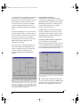
1
USB Interfaces Manual Cover/Win 10/10/00 11:37 AM Page 1
C
Composite
M
Y
CM
MY
CY CMY
K
!USB Interfaces Manual Book Page 0 Tuesday, October 10, 2000 12:43 PM
Mark of the Unicorn License Agreement and Limited
Warranty on Software
TO PERSONS WHO PURCHASE OR USE THIS PRODUCT: carefully read all
the terms and conditions of this agreement before using this software package.
Using this software package indicates your acceptance of the terms and conditions
of this license agreement.
Mark of the Unicorn, Inc. (“MOTU”) owns both this program and its documentation.
Both the program and the documentation are protected under applicable copyright
laws. Your right to use the program and the documentation are limited to the terms
and conditions described herein.
License
YOU MAY: (a) use the enclosed program on a single computer; (b) physically
transfer the program from one computer to another provided that the program is
used on only one computer at a time and that you remove any copies of the
program from the computer from which the program is being transferred; (c) make
copies of the program solely for backup purposes.You must reproduce and include
the copyright notice on a label on any backup copy.
YOU MAY NOT: (a) distribute copies of the program or the documentation to
others; (b) rent, lease or grant sublicenses or other rights to the program; (c)
provide use of the program in a computer service business, network, time-sharing,
multiple CPU or multiple user arrangement without the prior written consent of
MOTU; (d) translate or otherwise alter the program or related documentation
without the prior written consent of MOTU.
Term
Your license to use the program and documentation will automatically terminate if
you fail to comply with the terms of this Agreement. If this license is terminated you
agree to destroy all copies of the program and documentation.
Limited Warranty
MOTU warrants to the original licensee that the disk(s) on which the program is
recorded be free from defects in materials and workmanship under normal use for
a period of ninety (90) days from the date of purchase as evidenced by a copy of
your receipt. If failure of the disk has resulted from accident, abuse or misapplication of the product, then MOTU shall have no responsibility to replace the disk(s)
under this Limited Warranty.
THIS LIMITED WARRANTY AND RIGHT OF REPLACEMENT IS IN LIEU OF,
AND YOU HEREBY WAIVE, ANY AND ALL OTHER WARRANTIES, BOTH
EXPRESS AND IMPLIED, INCLUDING BUT NOT LIMITED TO WARRANTIES
OF MERCHANTABILITY AND FITNESS FOR A PARTICULAR PURPOSE. THE
LIABILITY OF MOTU PURSUANT TO THIS LIMITED WARRANTY SHALL BE
LIMITED TO THE REPLACEMENT OF THE DEFECTIVE DISK(S), AND IN NO
EVENT SHALL MOTU BE LIABLE FOR INCIDENTAL OR CONSEQUENTIAL
DAMAGES, INCLUDING BUT NOT LIMITED TO LOSS OF USE, LOSS OF
PROFITS, LOSS OF DATA OR DATA BEING RENDERED INACCURATE, OR
LOSSES SUSTAINED BY THIRD PARTIES EVEN IF MOTU HAS BEEN
ADVISED OF THE POSSIBILITY OF SUCH DAMAGES. THIS WARRANTY
GIVES YOU SPECIFIC LEGAL RIGHTS WHICH MAY VARY FROM STATE TO
STATE. SOME STATES DO NOT ALLOW THE LIMITATION OR EXCLUSION OF
LIABILITY FOR CONSEQUENTIAL DAMAGES, SO THE ABOVE LIMITATION
MAY NOT APPLY TO YOU.
Update Policy
In order to be eligible to obtain updates of the program, you must complete and
return the attached Mark of the Unicorn Purchaser Registration Card to MOTU.
General
This License Agreement shall be governed by the laws of the Commonwealth of
Massachusetts and shall inure to the benefit of MOTU, its successors, administrators, heirs and assigns.
Copyright Notice
Copyright © 2000, 1999 by Mark of the Unicorn, Inc. All rights reserved. No part of
this publication may be reproduced, transmitted, transcribed, stored in a retrieval
system, or translated into any human or computer language, in any form or by any
means whatsoever, without express written permission of Mark of the Unicorn,
Inc., 1280 Massachusetts Avenue, Cambridge, MA, 02138, U.S.A.
Limited Warranty on Hardware
Mark of the Unicorn, Inc. and S&S Research (“MOTU/S&S”) warrant this
equipment against defects in materials and workmanship for a period of NINETY
(90) DAYS from the date of original retail purchase. This warranty applies only to
hardware products; MOTU software is licensed and warranted pursuant to
separate written statements.
If you discover a defect, first write or call Mark of the Unicorn at (617) 576-2760 to
obtain a Return Merchandise Authorization Number. No service will be performed
on any product returned without prior authorization. MOTU will, at its option, repair
or replace the product at no charge to you, provided you return it during the
warranty period, with transportation charges prepaid, to Mark of the Unicorn, Inc.,
1280 Massachusetts Avenue, MA 02138. You must use the product’s original
packing material for in shipment, and insure the shipment for the value of the
product. Please include your name, address, telephone number, a description of
the problem, and the original, dated bill of sale with the returned unit and print the
Return Merchandise Authorization Number on the outside of the box below the
shipping address.
This warranty does not apply if the equipment has been damaged by accident,
abuse, misuse, or misapplication; has been modified without the written
permission of MOTU, or if the product serial number has been removed or defaced.
ALL IMPLIED WARRANTIES, INCLUDING IMPLIED WARRANTIES OF
MERCHANTABILITY AND FITNESS FOR A PARTICULAR PURPOSE, ARE
LIMITED IN DURATION TO NINETY (90) DAYS FROM THE DATE OF THE
ORIGINAL RETAIL PURCHASE OF THIS PRODUCT.
THE WARRANTY AND REMEDIES SET FORTH ABOVE ARE EXCLUSIVE AND
IN LIEU OF ALL OTHERS, ORAL OR WRITTEN, EXPRESS OR IMPLIED. No
MOTU/S&S dealer, agent, or employee is authorized to make any modification,
extension, or addition to this warranty.
MOTU/S&S ARE NOT RESPONSIBLE FOR SPECIAL, INCIDENTAL, OR
CONSEQUENTIAL DAMAGES RESULTING FROM ANY BREACH OF
WARRANTY, OR UNDER ANY LEGAL THEORY, INCLUDING LOST PROFITS,
DOWNTIME, GOODWILL, DAMAGE OR REPLACEMENT OF EQUIPMENT
AND PROPERTY AND COST OF RECOVERING REPROGRAMMING, OR
REPRODUCING ANY PROGRAM OR DATA STORED IN OR USED WITH
MOTU/S&S PRODUCTS.
Some states do not allow the exclusion or limitation of implied warranties or liability
for incidental or consequential damages, so the above limitation or exclusion may
not apply to you. This warranty gives you specific legal rights, and you may have
other rights which vary from state to state.
MIDI Timepiece, MIDI Express, micro express and Mark of the Unicorn are
trademarks of Mark of the Unicorn, Inc.
This equipment has been type tested and found to comply with the limits for a class B digital device,
pursuant to Part 15 of the FCC Rules. These limits are designed to provide reasonable protection
against harmful interference in a residential installation. This equipment generates, uses, and can
radiate radio frequency energy and, if not installed and used in accordance with the instruction manual,
may cause harmful interference to radio communications. However, there is no guarantee that
interference will not occur in a particular installation. If this equipment does cause interference to radio
or television equipment reception, which can be determined by turning the equipment off and on, the
user is encouraged to try to correct the interference by any combination of the following measures:
• Relocate or reorient the receiving antenna
• Increase the separation between the equipment and the receiver
• Plug the equipment into an outlet on a circuit different from that to which the receiver is connected
If necessary, you can consult a dealer or experienced radio/television technician for additional
assistance.
PLEASE NOTE: only equipment certified to comply with Class B (computer input/output devices,
terminals, printers, etc.) should be attached to this equipment, and it must have shielded interface
cables in order to comply with the Class B FCC limits on RF emissions.
WARNING: changes or modifications to this unit not expressly approved by the party
responsible for compliance could void the user's authority to operate the equipment.
!USB Interfaces Manual Book Page 1 Tuesday, October 10, 2000 12:43 PM
MOTU USB MIDI Interfaces
User’s Guide for Windows
MIDI Timepiece AV-USB
MIDI Express XT-USB
micro express-USB
Mark of the Unicorn, Inc.
1280 Massachusetts Avenue
Cambridge, MA 02138
Business voice: (617) 576-2760
Business fax: (617) 576-3609
Tech support fax: (617) 354-3068
Tech support email: [email protected]
Web site: http://www.motu.com
!USB Interfaces Manual Book Page 2 Tuesday, October 10, 2000 12:43 PM
SAFETY PRECAUTIONS AND ELECTRICAL REQUIREMENTS
WARNING: TO REDUCE THE RISK OF FIRE OR ELECTRICAL SHOCK, DO NOT EXPOSE THIS APPLIANCE TO RAIN OR OTHER MOISTURE.
CAUTION: TO REDUCE THE RISK OF ELECTRICAL SHOCK, DO NOT REMOVE COVER. NO USER-SERVICEABLE PARTS INSIDE. REFER SERVICING TO
QUALIFIED SERVICE PERSONNEL.
WARNING: DO NOT PERMIT FINGERS TO TOUCH THE TERMINALS OF PLUGS WHEN INSTALLING OR REMOVING THE PLUG TO OR FROM THE OUTLET.
WARNING: IF NOT PROPERLY GROUNDED THE MOTU USB MIDI interface COULD CAUSE AN ELECTRICAL SHOCK.
The MOTU USB MIDI interface is equipped with a three-conductor cord and grounding type plug which has a grounding prong, approved by Underwriters' Laboratories and the Canadian Standards
Association. This plug requires a mating three-conductor grounded type outlet as shown in Figure A below.
If the outlet you are planning to use for the MOTU USB MIDI interface is of the two prong type, DO NOT REMOVE OR ALTER THE GROUNDING PRONG IN ANY MANNER. Use an adapter as
shown below and always connect the grounding lug to a known ground. It is recommended that you have a qualified electrician replace the TWO prong outlet with a properly grounded THREE prong
outlet. An adapter as illustrated below in Figure B is available for connecting plugs to two-prong receptacles.
Figure A
Figure B
Grounding lug
Screw
3-prong plug
Make sure this is connected
to a known ground.
3-prong plug
Grounding prong
Two-prong receptacle
Properly grounded 3-prong outlet
Adapter
WARNING: THE GREEN GROUNDING LUG EXTENDING FROM THE ADAPTER MUST BE CONNECTED TO A PERMANENT GROUND SUCH AS TO A
PROPERLY GROUNDED OUTLET BOX. NOT ALL OUTLET BOXES ARE PROPERLY GROUNDED.
If you are not sure that your outlet box is properly grounded, have it checked by a qualified electrician. NOTE: The adapter illustrated is for use only if you already have a properly grounded two-prong
receptacle. Adapter is not allowed in Canada by the Canadian Electrical Code. Use only three wire extension cords which have three-prong grounding type plugs and three-prong receptacles which
will accept the MOTU USB MIDI interface plug.
IMPORTANT SAFEGUARDS
1.
2.
3.
4.
5.
6.
7.
8.
Read instructions - All the safety and operating instructions should be read before operating the MOTU USB MIDI interface.
Retain instructions - The safety instructions and owner's manual should be retained for future reference.
Heed Warnings - All warnings on the MOTU USB MIDI interface and in the owner's manual should be adhered to.
Follow Instructions - All operating and use instructions should be followed.
Cleaning - Unplug the MOTU USB MIDI interface from the computer before cleaning and use a damp cloth. Do not use liquid or aerosol cleaners.
Overloading - Do not overload wall outlets and extension cords as this can result in a risk of fire or electrical shock.
Power Sources - This MOTU USB MIDI interface should be operated only from the type of power source indicated on the marking label.If you are not sure of the type of power supply to your location, consult your local power company.
Power-Cord Protection - Power-supply cords should be routed so that they are not likely to be walked on or pinched by items placed upon or against them. Pay particular attention to cords and plugs, convenience receptacles, and
the point where they exit from the MOTU USB MIDI interface.
9. Lightning - For added protection for the MOTU USB MIDI interface during a lightning storm, unplug it from the wall outlet.This will prevent damage to the MOTU USB MIDI interface due to lightning and power line surges.
10. Servicing - Do not attempt to service this MOTU USB MIDI interface yourself as opening or removing covers will expose you to dangerous voltage and other hazards. Refer all servicing to qualified service personnel.
11. Damage Requiring Service - Unplug the MOTU USB MIDI interface from the computer and refer servicing to qualified service personnel under the following conditions.
a. When the power supply cord or plug is damaged.
b. If liquid has been spilled or objects have fallen into the MOTU USB MIDI interface.
c. If the MOTU USB MIDI interface has been exposed to rain or water.
d. If the MOTU USB MIDI interface does not operate normally by following the operating instructions in the owner's manual.
e. If the MOTU USB MIDI interface has been dropped or the cabinet has been damaged.
f. When the MOTU USB MIDI interface exhibits a distinct change in performance, this indicates a need for service.
12. Replacement Parts - When replacement parts are required, be sure the service technician has used replacement parts specified by the manufacturer or have the same characteristics as the original part. Unauthorized substitutions
may result in fire, electric shock or other hazards.
13. Safety Check - Upon completion of any service or repairs to this MOTU USB MIDI interface, ask the service technician to perform safety checks to determine that the product is in safe operating conditions.
ENVIRONMENT
Operating Temperature: 10°C to 40°C (50°F to 104°)
AVOID THE HAZARDS OF ELECTRICAL SHOCK AND FIRE
Do not handle the power cord with wet hands. Do not pull on the power cord when disconnecting it from an AC wall outlet. Grasp it by the plug.
INPUT
Line Voltage: 100 - 120 volts AC, RMS (US and Japan) or 220 - 250 volts AC, RMS (Europe). Frequency: 47 - 63 Hz single phase. Power: 7 watts maximum.
CAUTION: DANGER OF EXPLOSION IF BATTERY IS REPLACED. REPLACE ONLY WITH THE SAME OR EQUIVALENT TYPE RECOMMENDED BYMANUFACTURER. DISPOSE OF USED BATTERY ACCORDING TO MANUFACTURER’S INSTRUCTIONS.
!USB Interfaces Manual Book Page iii Tuesday, October 10, 2000 12:43 PM
CHAPTER
Contents
Part I: For All Users
7
Packing List and
Computer Requirements
9
Installing Your MOTU Interface
19
Installing the MOTU USB MIDI Driver and
Console Software
21
SMPTE Sync and MMC with a Windows
Sequencer
Part II: For XT & Micro Users
27
Working with Presets
31
Using Micro Express Console
51
Using MIDI Express XT Console
71
SMPTE Synchronization
77
MIDI Machine Control
Part III: For MTP AV Users
83
Using MIDI Timepiece AV Console
101
Using the Front Panel LCD
117
Synchronization with the AV
131
MIDI Machine Control with the AV
137
Synchronizing Pro Tools with the AV
Part IV: Appendices
141
Glossary
145
SMPTE Synchronization Basics
149
Troubleshooting and Customer Support
153
Index
III
!USB Interfaces Manual Book Page iv Tuesday, October 10, 2000 12:43 PM
IV
Part I
For All Users
All Users
!USB Interfaces Manual Book Page 5 Tuesday, October 10, 2000 12:43 PM
All Users
!USB Interfaces Manual Book Page 6 Tuesday, October 10, 2000 12:43 PM
Packing list Page 7 Tuesday, August 28, 2001 4:35 PM
CHAPTER 1
Packing List and
Computer Requirements
THANK YOU FOR CHOOSING MOTU
MIDI CABLES NOT INCLUDED
Thank you for purchasing a MOTU USB MIDI
interface. Please read the important information in
this chapter before using it.
To connect each of your MIDI devices to your
MOTU MIDI interface, you need MIDI cables,
purchased separately. Talk to your music dealer to
decide how many you need.
PLEASE REGISTER TODAY
Please send in the registration card included with
your MOTU MIDI interface. As a registered user,
you will be eligible to receive on-line technical
support email and announcements about product
enhancements as soon as they become available.
Only registered users receive these special update
notices, so please, complete and mail this
registration card!
COMPUTER REQUIREMENTS
Your MOTU MIDI interface will run with any
USB-equipped PC compatible running
Windows 2000, Windows Me or Windows 98.
MIDI SOFTWARE COMPATIBILITY
Your MOTU USB MIDI Interface works with all
MIDI software that operates under Windows 2000,
Windows Me or Windows 98.
Thank you for taking the time to register your new
Mark of the Unicorn product!
GETTING STARTED
PACKING LIST
Follow the directions in the next few chapters of
this guide to successfully install and begin using
your new MOTU USB MIDI interface.
Your MOTU USB MIDI Interface is shipped with
the items listed below. If any of these items are not
present when you first open the box, please
immediately contact your dealer or Mark of the
Unicorn.
■
MOTU USB MIDI Interface
■
Power cord
■
USB cable
■
CD with software drivers
■
Manual
■
Product registration card
FAMILIARITY WITH WINDOWS
This manual assumes that your are familiar with
using a Windows computer. If not, please review
your Windows User’s Guide before proceeding.
VISIT OUR WEB SITE FOR SOFTWARE
UPDATES
Driver updates are posted on our web site as soon
as they become available, so check our web site for
the latest drivers: www.motu.com
7
!USB Interfaces Manual Book Page 8 Tuesday, October 10, 2000 12:43 PM
8
P AC K I NG L I ST AND C O M P UT E R R E Q UI R E M E NT S
!USB Interfaces Manual Book Page 9 Tuesday, October 10, 2000 12:43 PM
CHAPTER 2
Installing Your MOTU Interface
FOR ALL MOTU INTERFACE MODELS
Connecting the power cord. . . . . . . . . . . . . . . . . . .9
If you have several MOTU interfaces, see chapter 3,
“Installing Multiple Interfaces” (page 17).
Connecting a USB computer . . . . . . . . . . . . . . . . .9
Connecting MIDI gear. . . . . . . . . . . . . . . . . . . . . . .9
The flat,“Type A” USB plug
connects to the computer.
MIDI connections worksheet . . . . . . . . . . . . . . . .11
SMPTE Time Code sync connections. . . . . . . . .12
Connecting a pedal or foot switch . . . . . . . . . . . .13
Connecting an audio click source . . . . . . . . . . . .13
Connecting multiple USB interfaces. . . . . . . . . .17
Connecting multiple USB interfaces. . . . . . . . . .17
FOR MIDI TIMEPIECE AV USERS
Connecting ADATs . . . . . . . . . . . . . . . . . . . . . . . . .14
Connecting Video . . . . . . . . . . . . . . . . . . . . . . . . . .14
Figure 2-1: You can plug the Type A connector into a Type A jack
directly on the computer itself, a USB keyboard connected to the
computer, or any other USB device already connected to the
computer that has an available Type A USB jack.
Connecting Word clock . . . . . . . . . . . . . . . . . . . . .15
Connecting Pro Tools “SuperClock”. . . . . . . . . .15
The square,“Type B” USB plug
connects to the MIDI interface.
Connecting an Alesis LRC. . . . . . . . . . . . . . . . . . .15
Connecting a Macintosh . . . . . . . . . . . . . . . . . . . .16
CONNECTING THE POWER CORD
Plug the power cord into your MOTU MIDI
Interface and then plug the other end into a
grounded power outlet. We recommend that you
leave the interface switched off while making cable
connections during installation.
Figure 2-2: The square Type B plug goes into your MOTU interface.
CONNECTING A USB COMPUTER
CONNECTING MIDI GEAR
First, make sure that the interface’s power switch is
turned off. Using the USB cable included with your
MOTU MIDI interface, put the Type A plug into a
Type A USB jack on the computer, a USB hub, or
any other USB device connected to the computer
that has an available Type A USB jack. The USB
cable allows the computer to communicate with all
MIDI devices connected to your MOTU MIDI
interface.
Connect each MIDI device’s MIDI IN jack to a
MIDI OUT jack on your MOTU MIDI interface as
shown by Connection A below. Conversely,
connect the MIDI OUT jack on the MIDI device to
one of the MIDI IN jacks on your MOTU MIDI
interface as shown by Connection B.
9
!USB Interfaces Manual Book Page 10 Tuesday, October 10, 2000 12:43 PM
MOTU
MIDI interface
rear panel
MIDI
OUT
Connection A
MIDI
IN
MIDI
cables
Connection B
MIDI Device
MIDI MIDI
IN OUT
Figure 2-3: Connecting a MIDI device to your MOTU MIDI interface. If
you are connecting a sound module or other device that does not
need to transmit MIDI data, you only need to make connection A
shown above. Conversely, if the device is a MIDI controller such as a
drum pad or guitar controller, you only need to make Connection B.
One-way MIDI connections
MIDI devices that do not receive MIDI data, such
as a dedicated keyboard controller, guitar
controller, or drum pad, only need Connection B
shown in Figure 2-3. Similarly, devices that never
send data, such as a sound module, only need
Connection A. However, if you plan to use editor/
librarian software with the sound module, or if you
need to get system exclusive bulk dumps from it,
make both connections. In general, make both
connections for any device that needs to both send
and receive MIDI data.
☛ MOTU MIDI interfaces do not require that
you use the same numbered MIDI IN and MIDI
OUT for each device, but experience shows that
your system will be easier to work with if you do.
Connecting additional gear with MIDI THRUs
If you use up all of the MIDI OUTs on your MOTU
MIDI interface, and you still have more gear to
connect, run a MIDI cable from the MIDI THRU
of a device already connected to the interface to the
MIDI IN on the additional device as shown below
in Figure 2-4. The two devices then share the same
MIDI OUT port on the MIDI interface. This means
that they share the same set of 16 MIDI channels,
so try to do this with devices that receive on only
one MIDI channel (such as effects modules) so
their receive channels don’t conflict with one
another.
MOTU
MIDI interface
rear panel
MIDI
OUT
MIDI Device
MIDI
IN
MIDI
THRU
MIDI
cable
MIDI IN
Additional device
Figure 2-4: Connecting additional devices with MIDI THRU ports.
10
I NST AL L I NG Y O UR M O T U I NT E R F AC E
!USB Interfaces Manual Book Page 11 Tuesday, October 10, 2000 12:43 PM
MIDI CONNECTIONS WORKSHEET
Here’s a suggestion. If you have more than a few
pieces of gear connected to your MOTU MIDI
interface, jot down which device is connected to
each input and output in the worksheet below.
MIDI IN
MIDI OUT
1
1
2
2
3
3
4
4
5
5
6
6
7
7
8
8
11
I N STA LL I N G Y O U R MO TU I N TER FA C E
!USB Interfaces Manual Book Page 12 Tuesday, October 10, 2000 12:43 PM
SMPTE TIME CODE SYNC CONNECTIONS
Your MOTU MIDI interface is both a SMPTE time
code converter and generator. As a converter, it
locks (slaves) to incoming longitudinal SMPTE
time code (LTC) and converts it to MIDI Time
Code (MTC) and reshaped LTC. As a generator, it
produces both LTC and MTC time code, either
running under its own internal clock or while
slaved to external time code (or other time base).
When making the SMPTE time code connections
described in the following sections, do not pass the
signal through any type of signal processing
equipment. Use shielded quarter-inch audio
cables.
Connecting a SMPTE time code destination
Connect the SMPTE OUT port of your MOTU
MIDI interface to the SMPTE time code input of
any destination device that accepts SMPTE time
code as shown in Figure 2-6. For example, time
code can be recorded on an outside track of a
multitrack tape recorder so that everything can
subsequently be synchronized to the multitrack.
Other examples of a SMPTE time code destination
are systems that have the ability to slave to SMPTE
time code, such as stand-alone hard disk recording
systems, digital audio workstations, or automated
mixing consoles.
For a complete explanation of synchronization, see
chapter 8, “SMPTE Synchronization” (page 71) or
chapter 12, “Synchronization with the AV”
(page 117).
MOTU MIDI Interface
SMPTE OUT
Shielded, quarter-inch audio cable
Connecting a SMPTE time code source
Connect any SMPTE time code source, such as the
SMPTE timecode track on an analog multitrack
tape deck, to the SMPTE IN port on your MOTU
MIDI interface as shown in Figure 2-5. (For
information about recording time code tracks, see
“Striping SMPTE” on page 73.)
Analog audio tape recorder
SMPTE or Audio in
Examples of a SMPTE
time code destinations
Analog audio tape recorder
Video tape recorder
Video tape recorder
Figure 2-6: Connecting a SMPTE time code destination.
Examples of a SMPTE
time code source
Audio or SMPTE out
Shielded, quarter-inch audio cable
MOTU MIDI Interface
SMPTE IN
Figure 2-5: Connecting a SMPTE time code source.
12
I NST AL L I NG Y O UR M O T U I NT E R F AC E
!USB Interfaces Manual Book Page 13 Tuesday, October 10, 2000 12:43 PM
CONNECTING A PEDAL OR FOOT SWITCH
CONNECTING AN AUDIO CLICK SOURCE
If you would like to use a foot pedal or foot switch
with your MOTU MIDI interface, connect it as
shown below in Figure 2-7. For more information
about how a pedal input can be used, see the
section below that applies to you:
If you would like to convert an audio click to MIDI,
connect the audio click source to the Pedal input as
using a shielded, quarter-inch audio cable as
shown below in Figure 2-8. For more information
about converting an audio tempo source (such as a
click, bass drum, tape deck signal, or other audio
tempo source) to MIDI, see “Programming Pedal
A to convert an audio click” on page 112.
■ For micro express users: “Pedal window” on
page 46
■ For Express XT users: “Pedal window” on
page 66
■ For MIDI Timepiece AV users: “Programming
the pedal inputs” on page 110
For a MIDI Timepiece AV,
you can connect a pedal or foot switch to
either the Pedal A port on the rear panel or
the Pedal B port on the front panel.
☛
On a MIDI Timepiece AV, only PEDAL A (on
the rear panel) can be used for
click-to-MIDI conversion.
Examples of
audio click sources
Shielded
quarter-inch
audio cable
Drum machine
Click track
For a MIDI Timepiece AV, connect a pedal or foot
switch to the Pedal jack on the rear panel.
For a MIDI Express XT-USB,
connect a pedal or foot
switch to the Pedal jack on
the front panel.
For a MIDI Express XT-USB,
connect an audio click
source to the Pedal jack on
the front panel.
For a micro express USB, connect a pedal or foot
switch to the Pedal jack on the rear panel.
For a micro express USB, connect an audio click
source to the Pedal jack on the rear panel.
Figure 2-7: Connecting a foot switch or foot pedal.
Figure 2-8: Connecting an audio click input. Only the Pedal A input
on the rear panel of the MIDI Timepiece AV can be used as a click
input.
13
I N STA LL I N G Y O U R M O TU I N TER FA C E
!USB Interfaces Manual Book Page 14 Tuesday, October 10, 2000 12:43 PM
CONNECTING ADATS
CONNECTING VIDEO
(For the MIDI Timepiece AV only)
The MIDI Timepiece AV can serve as an ADAT
sync master device, providing sample-accurate
address and phase lock to one or more ADATs (or
other ADAT sync-compatible devices). ADAT sync
provides sample-accurate synchronizing and
locating between the MTP AV and all devices on
the ADAT sync chain.
(For the MIDI Timepiece AV only)
The MIDI Timepiece AV can synchronize to any
incoming video signal, from a standard video tape
recorder (VTR) to distributed house sync
(blackburst). If your video source is a VTR of some
kind, the video signal from the VTR will need to be
distributed to both the MIDI Timepiece AV and
your video monitor. This can be accomplished
with the video thru jack found on some types of
video monitors as shown in Figure 2-11.
Using the ADAT sync cable supplied with your
ADAT, connect the ADAT SYNC OUT of the MIDI
Timepiece AV to the SYNC IN port of the ADAT as
shown below in Figure 2-9. Don’t worry about
setting the ADAT device ID: the MTP AV sets it
automatically.
Video out
Video tape recorder
Shielded BNC cables
Video in
Video thru
Video monitor
ADAT
MIDI Timepiece AV
Video sync in
ADAT
sync cable
SYNC
IN
Figure 2-9: Connecting an Alesis ADAT.
MIDI Timepiece AV
If you have several ADATs, you can chain the rest of
them to the one connected to the MIDI
Timepiece AV as shown below in Figure 2-10.
ADAT
MIDI Timepiece AV
ADAT
sync cable
Figure 2-11: Connecting video via the video thru of a video monitor.
If your video monitor does not support video thru,
use a video distribution amplifier to distribute the
source video signal to both the Timepiece AV and
the monitor as shown in Figure 2-12.
SYNC
IN
Video monitor
ADAT
SYNC OUT
port
ADAT
Sync In
Sync Out
ADAT
sync cables
Video out
Video tape recorder
Video distribution amp
Video in
Video in
Video out
Video out
Video sync in
Sync In
Sync Out
Sync In
Sync Out
etc.
MIDI Timepiece AV
Figure 2-12: Connecting video via a video distribution amplifier.
Figure 2-10: Connecting multiple ADATs.
14
I NST AL L I NG Y O UR M O T U I NT E R F AC E
!USB Interfaces Manual Book Page 15 Tuesday, October 10, 2000 12:43 PM
CONNECTING WORD CLOCK
CONNECTING PRO TOOLS “SUPERCLOCK”
(For the MIDI Timepiece AV only)
The MIDI Timepiece AV can serve as a word clock
sync master device, providing sample-accurate
phase lock for any standard word clock device.
Word clock allows you to resolve hard disk
recorders, digital tape decks, digital mixers and
other digital audio devices to video, SMPTE time
code, MIDI time code, or the MIDI Timepiece AV’s
internal audio clock.
(For the MIDI Timepiece AV only)
The MIDI Timepiece AV can serve as a Digidesign
Pro Tools “superclock” (256x word clock) sync
master device, providing sample-accurate phase
lock for any Pro Tools system. Like word clock,
super clock allows you to resolve Pro Tools to
video, SMPTE time code, MIDI time code, or the
MIDI Timepiece AV’s internal audio clock.
In most situations, you’ll want to slave your word
clock device to the MIDI Timepiece AV with both
the word clock and SMPTE time code connections
shown below in Figure 2-13. In this scenario, the
word clock device follows the MIDI Timepiece AV
for transport control.
To slave your Pro Tools hardware to the MTP AV,
make the word sync connection shown below in
Figure 2-13.
MIDI Timepiece AV
WORD SYNC OUT
Shielded BNC cable
Word SYNC OUT
Shielded BNC cable
Word clock IN
“SLAVE CLOCK’ IN or
SUPERCLOCK’ IN
SMPTE OUT
Shielded
audio cable
SMPTE IN
Pro Tools audio interface
Figure 2-14: Connecting a word clock device.
CONNECTING AN ALESIS LRC
Figure 2-13: Connecting a word clock device.
In the above example, if you wanted to use the
Yamaha 02R as the transport master, you would
reverse the SMPTE time code connection, feeding
SMPTE OUT of the mixer to SMPTE IN on the
MIDI Timepiece AV.
(For the MIDI Timepiece AV only)
The Pedal B jack on the front panel of the MIDI
Timepiece AV can serve as an input for the
Alesis LRC™ remote controller, or any device that
emulates the LRC, such as the Fostex Model 8312™
controller. Doing so gives you control of the MIDI
Timepiece AV (and all devices slaving to it) from
the LRC transport controls.
Alesis LRC
or similar device
Figure 2-15: Connecting an Alesis LRC remote controller (or any LRCcompatible MMC controller) to a MIDI Timepiece AV.
15
I N STA LL I N G Y O U R M O TU I N TER FA C E
!USB Interfaces Manual Book Page 16 Tuesday, October 10, 2000 12:43 PM
CONNECTING A MACINTOSH
(For the MIDI Timepiece AV only)
The MIDI Timepiece AV-USB has two serial ports
for connection to serial-port equipped Macintosh
computers. If you would like to connect a serial
Macintosh to the MIDI Timepiece AV-USB at the
same time as your Windows PC, you can connect it
to the ‘NET’ serial port, as shown below in
Figure 2-16. Both computers have access to all
MIDI devices connected to the MIDI Timepiece
AV-USB. MIDI software can run on both
computers at the same time, and both programs
can send and receive MIDI data to the MIDI
Timepiece at the same time.
Making the ‘NET’ port setting
After you have connected the Macintosh, you need
to tell the MIDI Timepiece AV that a Mac is
connected to its NET port. To do so:
1 Switch on the MTP AV.
When you switch on the MTP AV for the first time,
you’ll see the following in it’s LCD:
BASE-SETUP
BaseSetup 1
1
YE
Figure 2-17
2 Turn the WINDOW knob clockwise two clicks
to the right, or if necessary, turn it back and forth
until you see what is shown below in Figure 2-18.
USB-equipped
computer
GLOBAL HARDWARE
SETUP
USB
cable
MIDI Timepiece AV-USB
E
Figure 2-18
NET port
AppleTalk
Cable
serial port
Figure 2-16: Adding a serial-port equipped Macintosh to the NET
port.
☛ Be sure to choose “MAC” instead of “MTP”
for the NET port setting in the MIDI
Timepiece AV’s front panel LCD display. For
details, see the next section.
3 Once you see Figure 2-18 in the display, turn the
CURSOR knob clockwise three clicks, or until you
see what is shown below in Figure 2-19. The phrase
“MAC” will blink to indicate that it can be changed
with the VALUE knob.
THIS BOX ID 1-8
D NET
PORT=MAC
E
Figure 2-19
4 Turn the VALUE KNOB until the NET PORT
setting = MAC.
16
I NST AL L I NG Y O UR M O T U I NT E R F AC E
!USB Interfaces Manual Book Page 17 Tuesday, October 10, 2000 12:43 PM
CONNECTING MULTIPLE USB INTERFACES
The flat,“Type A” USB plug on the
USB cable from each MOTU interface
connects to the USB hub.
The USB (Universal Serial Bus) specification allows
you to connect multiple MOTU interfaces to a
single PC. You can mix and match any combination
of MOTU USB interfaces to suit your needs.
The USB (Universal Serial Bus) specification allows
many USB devices — theoretically up to 127 — to
be connected to a single computer. However, many
USB devices, including all MOTU USB interfaces,
reserve USB bandwidth, so the theoretical and
practical limits for MOTU interfaces are
considerably fewer. In theory, the maximum
number of MOTU USB interfaces you can connect
to one computer is just over 30 interfaces.
Practically speaking, regardless of how slow or fast
your USB-equipped computer is, you should be
able to connect upwards of 10 or more MOTU USB
MIDI interfaces to the computer and still enjoy just
as much performance from each one as if it were
the only one connected. Just don’t try to run your
USB scanner or digital camera while playing back
and recording MIDI!
Standard USB Hub
USB
cables
Figure 2-20: An inexpensive, standard USB hub, such as the
machub4U™ shown above from Entrega, allows you to connect
multiple MOTU USB MIDI interfaces. You can even mix and match
different models of MOTU interfaces, using the combination that best
suites your needs for synchronization, number of MIDI ports, etc.
WHAT NEXT?
You’re ready to install software. Turn to chapter 3,
“Installing the MOTU USB MIDI Driver and
Console Software” (page 19).
For further details about USB, visit www.usb.org.
To connect multiple MOTU interfaces to a
computer, you’ll need an inexpensive device called
a USB Hub (purchased separately from your
computer peripherals dealer). A USB Hub has
multiple Type A ports on it, usually between 4 and
7 ports, to which you connect multiple USB MIDI
interfaces as shown in Figure 2-20. Connect them
to the hub in the standard fashion, as if you were
connecting them directly to the computer. If
needed, you can connect multiple hubs to each
other to get enough USB ports for your multiple
MOTU USB interfaces.
17
I N STA LL I N G Y O U R M O TU I N TER FA C E
!USB Interfaces Manual Book Page 18 Tuesday, October 10, 2000 12:43 PM
18
I NST AL L I NG Y O UR M O T U I NT E R F AC E
Installing Software Page 19 Tuesday, August 28, 2001 4:55 PM
CHAPTER 3
Installing the MOTU USB MIDI Driver
and Console Software
Software installation will go a little more smoothly
if you turn off your interface before switching on
your computer. Don’t worry, however, if you’ve
already done so. Just follow the directions below.
To install the MOTU USB MIDI software:
1 Turn on your computer (if you haven’t already
done so).
2 If the Windows Add Hardware Wizard appears
during startup, do not proceed and exit from the
Wizard.
Instead of installing the MOTU USB MIDI drivers
manually via the Wizard, you will run the MOTU
USB software installer.
3 Insert the MOTU USB software installer CD in
the computer’s CD drive (if you haven’t already).
4 If the MOTU USB software installer program
does not automatically begin running, doubleclick SETUP.EXE on the installer CD to launch it.
5 Follow the directions the installer gives you.
That’s it!
WHAT GETS INSTALLED?
The MOTU USB software installer installs drivers
for your MOTU USB MIDI interface, as well as a
Console application that gives you access to many
of your interface’s features, including synchronization, MIDI processing and preset management.
You can find the console application in the
Windows Start menu under Programs>MOTU.
WHERE TO GO NEXT
Where you go next depends, of course, on what
you would like to do.
If you want to learn the front panel controls...
Turn to the chapter below that applies to you:
For the MIDI Express XT or micro express, see
chapter 5, “Working with Presets” (page 27).
■
For the MIDI Timepiece AV, see chapter 11,
“Using the Front Panel LCD” (page 101).
■
If you want to start using MIDI software with
your new MOTU interface...
All MOTU interfaces have factory default settings
that allow any MIDI software to communicate with
all MIDI devices connected to the interface. So
from here, you can turn to your software
documentation to get started.
If you want to program your interface...
Your MOTU interface console software is the “front
end” for the features in your MOTU interface. It
allows you to configure and program the powerful
MIDI routing and processing features in the
interface. You can graphically make direct routings
from inputs and outputs, stripe SMPTE time code,
create and save interface setups (which consist of
the entire internal configuration of the interface),
set up the pedal inputs, or other tasks.For details,
turn to the chapter that applies to you:
chapter 6, “Using Micro Express Console”
(page 31)
■
chapter 7, “Using MIDI Express XT Console”
(page 51)
■
chapter 10, “Using MIDI Timepiece AV
Console” (page 83)
■
19
Installing Software Page 20 Tuesday, August 28, 2001 4:55 PM
20
I N S TA L L I NG T HE M O T U USB M I DI DR I V E R AND C O NSO L E SO F T W AR E
!USB Interfaces Manual Book Page 21 Tuesday, October 10, 2000 12:43 PM
CHAPTER 4
SMPTE Sync and MMC with a
Windows Sequencer
USING MOTU USB MIDI PORTS
There are only a few simple preparations you need
to make to take advantage of the powerful MIDI
routing, SMPTE synchronization and MIDI
Machine Control (MMC) features of a MOTU
MIDI interface and any Windows sequencing
software that supports SMPTE synchronization
and MMC.
Once you have installed the MOTU USB MIDI
driver, you’ll notice that all MIDI inputs and
outputs are available to your MIDI programs. The
port names are abbreviated as shown below in
Figure 4-1.
Using MOTU USB MIDI ports. . . . . . . . . . . . . . .21
Slaving a Sequencer to SMPTE. . . . . . . . . . . . . . .22
Your Sequencer as a MMC controller . . . . . . . . .22
MMC control of record functions . . . . . . . . . . . .23
Routing Time Code to Other Devices. . . . . . . . .23
For further information. . . . . . . . . . . . . . . . . . . . .23
Figure 4-1: MOTU interface ports in Cakewalk Pro™. This example
shows the ports for the MIDI Express XT.
The MIDI data path
As for MIDI data arriving and leaving your
computer via the MOTU USB MIDI driver,
imagine it coming and going from the MOTU
MDI IN
MDI OUT
Event filtering
Channel
mapping
Figure 4-2: The path that MIDI data takes
through a MOTU USB interface data.
MOTU
MIDI Interface
data bus
Channel
mapping
Event filtering
Windows MIDI Ports
(Computer)
21
!USB Interfaces Manual Book Page 22 Tuesday, October 10, 2000 12:43 PM
interface as shown below in Figure 4-2. All
channelizing and filtering is applied before the
input data arrives at any software input port and
after it is sent from any software output port. This
is a great advantage as it frees up your computer
and MIDI software from having to deal with the
mundane (and time-consuming) chore of such
processing. Just configure your MOTU interface
and let it do all the work!
Sync Port
You’ll also see several other special MIDI ports in
addition to the regular MIDI ports. The first is the
“Sync” input port where all MIDI real time and
MIDI Time Code messages will arrive, regardless
of the physical MIDI input jack from which the
MOTU interface receives them. All other received
data will arrive at its input port as appropriate.
Out All port
You’ll also see a port called “Out All”. This port also
appears in your MIDI programs, allowing you to
send the same MIDI data out all MIDI output ports
at once.
MIDI ports and the console software
You do not need to have the MOTU interface
console software running in Windows to use the
MOTU interface with your sequencer. Also, as the
console does not compete with other MIDI
applications for the Windows MIDI ports, you can
freely open and close the console to make
adjustments or simply check the current settings
during your Windows session.
Figure 4-3: Slaving to the Sync port for SMPTE synchronization via
MIDI Time Code (MTC).
YOUR SEQUENCER AS A MMC CONTROLLER
If your sequencer supports MIDI Machine Control
(MMC), then it has the ability to serve as a MIDI
Machine Control transport master for any MMC
device in your studio, allowing you to play, stop,
and the device directly from your sequencer’s main
transport controls.
Your MOTU MIDI interface has the ability to serve
as a MMC transport slave, while at the same time
generating time code for other devices in your
studio. In doing so, the MOTU interface becomes a
central, stable time code “hub” for all of the devices
in your studio, allowing you play, stop, and cue
them all directly from your sequencer.
Cakewalk Pro or any other Windows
sequencer that support SMPTE sync and MMC
MIDI Time Code (MTC)
MIDI Machine Control
(MMC)
MOTU MIDI interface
SLAVING A SEQUENCER TO SMPTE
To slave a sequencer to SMPTE time code via a
MOTU MIDI interface, just connect the sequencer
to the Sync port, as demonstrated below in
Figure 4-3 for the Express XT and CakeWalk Pro™:
MIDI Time Code (MTC)
SMPTE (LTC)
Examples of
devices that can
slave to time code
Akai DR8
Roland VS-880
Figure 4-4: Your MOTU interface (a MIDI Express XT in this example)
can serve as a time code “hub” while you control it from your
sequencer via MMC transport commands.
22
SM P T E SY NC AND M M C W I T H A W I NDO W S SE Q UE NC E R
!USB Interfaces Manual Book Page 23 Tuesday, October 10, 2000 12:43 PM
The first step is to slave your sequencer to MIDI
Time Code as described in the previous section
(and shown in Figure 4-3).
of passing on MMC record commands from your
sequencer and the MMC device. Just send them
directly to the appropriate Windows MIDI port.
The next step is to establish MMC transport
control of the MOTU interface from your
sequencer. To do so, make sure your sequencer
knows the MMC Device ID of the MOTU
interface. The factory default ID of the MOTU
interface is 20. (If necessary, you can change it in
the console software.)
ROUTING TIME CODE TO OTHER DEVICES
MMC CONTROL OF RECORD FUNCTIONS
Some sequencers provide MMC remote control of
record features, such as record-arming tracks,
setting automatic punch-in and punch-out points,
punching in on the fly, and so forth. The MOTU
interface’s MMC capabilities, however, do not
come into play with record functions such as these.
It only handles MMC transport functions like
playing, stopping, and locating. For MMC record
functions, the MOTU interface serves only a means
Once you have successfully established MMC
control of the MOTU interface from your
sequencer as described in this chapter, you can
route MIDI Time Code (MTC) from the MOTU
interface to other devices in your studio to control
them remotely from your sequencer, as shown in
Figure 4-4. For more information, see “Sync
routing” on page 63.
FOR FURTHER INFORMATION
For further details about using SMPTE sync and
MMC, see the appropriate chapter below:
■ chapter 6, “Using Micro Express Console”
(page 31)
■ chapter 7, “Using MIDI Express XT Console”
(page 51)
■ chapter 10, “Using MIDI Timepiece AV
Console” (page 83)
23
SMPTE S Y N C A N D MMC W I TH A W I N DO W S SE Q UE NC E R
!USB Interfaces Manual Book Page 24 Tuesday, October 10, 2000 12:43 PM
24
SM P T E SY NC AND M M C W I T H A W I NDO W S SE Q UE NC E R
!USB Interfaces Manual Book Page 25 Tuesday, October 10, 2000 12:43 PM
XT& Micro Users
Part II
For XT & Micro Users
XT& Micro Users
!USB Interfaces Manual Book Page 26 Tuesday, October 10, 2000 12:43 PM
!USB Interfaces Manual Book Page 27 Tuesday, October 10, 2000 12:43 PM
CHAPTER 5
Working with Presets
OVERVIEW
This chapter describes your MOTU Express
interface’s eight factory presets and explains how
to:
The eight user presets can be configured any way
you wish, and they can be stored in the interface
hardware itself for later recall.
SELECTING A PRESET ON AN EXPRESS XT
Select a factory preset or one of eight user presets
from the front panel
■
■
Create your own user presets
Work with presets in the Express Console
software
■
■ Select presets using patch changes from any
MIDI source (such as a keyboard controller or
sequencer)
Factory versus user presets . . . . . . . . . . . . . . . . . .27
To select a preset from the front panel:
1 If you have a MIDI Express XT, press the BANK
button as needed to choose either the factory
preset bank or user preset bank. The Factory Preset
or User Preset LED will become lit.
2 Repeatedly press the SELECT button until the
LED below the program you want lights up.
As you repeatedly press the button, the LED cycles
through the eight programs.
Selecting a preset on an Express XT . . . . . . . . . .27
Selecting a preset on a micro express . . . . . . . . .27
Factory Presets. . . . . . . . . . . . . . . . . . . . . . . . . . . . .27
User Presets . . . . . . . . . . . . . . . . . . . . . . . . . . . . . . .30
Working with presets in Express Console . . . . .30
FACTORY VERSUS USER PRESETS
Your Express interface provides eight factory
presets and eight more user presets. Factory presets
are “hard-wired” and cannot be permanently
changed. If a factory preset is the current preset,
changes you make to your Express interface’s
settings will not be remembered unless you save
them to one of its eight user presets.
SELECTING A PRESET ON A MICRO EXPRESS
To select a preset from the front panel:
1 Repeatedly press the SELECT button until the
LED for the program you want lights up.
2 The SELECT button cycles through both the
factory and user presets, as indicated by the red
User LED and the green Factory LED.
FACTORY PRESETS
The eight factory presets provide you with
optimum cable routing, SMPTE, and other settings
for various common situations in which you will
use your Express interface. The eight factory preset
settings are listed on the front panel as shown
below:
27
!USB Interfaces Manual Book Page 28 Tuesday, October 10, 2000 12:43 PM
MIDI Express XT front panel preset controls
micro express front panel preset controls
Figure 5-1: The eight factory presets on the front panel of the
Express XT and micro express.
Each factory preset is described in the following
sections, including situations in which you would
find it useful.
Sequencer 30 fps
This preset is designed for MIDI software,
especially sequencing software, that supports
multi-cable interfaces such as your Express
interface.
This preset connects all inputs and outputs to the
computer. In addition, it sets the SMPTE sync
settings for lockup and striping at 30 frames per
second (fps).
Sequencer 25 fps
This preset is identical to the Sequencer 30 fps
above except that the frame rate is set to 25 frames
per second (fps) for converting and striping at
25 fps.
Live Keyboards
Use this preset when you want to route any
controller connected to a MIDI IN to all MIDI
outputs. This preset is ideal for quickly routing a
controller to a sound module and for using a MIDI
controller without a computer. If you have
connected both the MIDI IN and MIDI OUT of
your keyboard controller to your Express interface,
it is best to match the input/output MIDI port
numbers on your MOTU interface. For example, if
the controller is connected to MIDI IN port 3,
connect it to MIDI OUT port 3 as well. If you do so,
this preset prevents troublesome MIDI feedback
loops, which happen when the controller sends
data back to itself via your Express interface. This
preset avoids this problem by not sending data to
the port that has the same number. For example,
MIDI IN port 3 routes data to all MIDI OUT ports
except MIDI OUT number 3.
Merge All
With this preset, any device connected to a MIDI
IN will send data to all devices connected to your
Express interface outputs, including the computer.
This preset is ideal for troubleshooting because it
routes everything to everywhere; any incoming
data will be sent to all outputs. For example, if you
are not getting sound from a sound module when
you play notes on your controller, you can
eliminate MIDI routing as the cause of the problem
by temporarily using this preset. You can rest
assured that your Express interface is routing the
data to the module correctly, and you can then
focus your efforts on other possible causes, such as
bad MIDI cables, volume settings, etc.
Use this troubleshooting technique if you cannot
successfully record data into your sequencer on the
computer.
Merge Some
The Merge Some preset is similar to the Merge All
preset, except that it divides the inputs into two
groups: inputs 1-4 (1-2 on the micro express) are
routed to the computer only, while inputs 5-8 (3-4
on the micro express) are routed directly to all
outputs (but not the computer).
Dual Split
The Dual Split preset is similar to the Live
Keyboards preset, except that it splits the interface
into two sets of inputs and outputs.
28
W O R K I NG W I T H P R E SE T S
!USB Interfaces Manual Book Page 29 Tuesday, October 10, 2000 12:43 PM
For the micro express, input 1 is routed to outputs
1-3. Input 3 is routed to outputs 4-6.
For the Express XT, input 1 is routed to outputs
1-4. Input 5 is routed to outputs 5-8.
MIDI Machine/for the Express XT
This preset provides MIDI data, time code, and
MIDI Machine Control settings for using MIDI
Machine Control between devices without a
computer.
Inputs 1-4 are reserved for non-MMC devices
being routed to outputs 1-5, as well as the
computer.
Input 5 is also routed to the computer but not to
any of the MIDI outputs.
MIDI outputs 6, 7 and 8 are reserved for MIDI
Machine devices, as these ports are programmed
to receive MIDI Time Code and MMC transport
commands from the MIDI Express XT.
MIDI inputs 6, 7 and 8 are intended for MMC
controller devices, and they are each programmed
slightly differently to accommodate three different
scenarios. Input 6 routes MIDI data only to outputs
6, 7 and 8. Input 7 routes MMC to the MIDI
Express XT only. Input 8 does a combination of
inputs 6 and 7.
MIDI Machine/for the micro express
This preset provides MIDI data, time code, and
MIDI Machine Control settings for using MIDI
Machine Control between devices without a
computer.
Inputs 1-2 are reserved for non-MMC devices
being routed to outputs 1-4, as well as the
computer.
MIDI outputs 5 and 6 are reserved for MIDI
Machine devices, as these ports are programmed
to receive MIDI Time Code and MMC transport
commands from the micro express.
MIDI inputs 3 and 4 are intended for MMC
controller devices, and they are each programmed
slightly differently to accommodate several
different scenarios. Input 3 routes MMC to the
micro express only. Input 4 routes MIDI data only
to output 6.
Direct
This preset causes your Express interface to
function like a simple 1 IN/8 OUT or 1 IN/ 6 OUT
MIDI interface, respectively. All of the extra
routing, merging, muting, rechannelizing, and
running status features are disabled. Your Express
interface applies no processing whatsoever to
MIDI data as it is sent to and from the computer.
This mode is referred to as Direct Connect mode
through this manual.
Input 1 connects to the computer, and the
computer connects to all 8 (or 6) outputs. But none
of the inputs are connected directly to the outputs.
This preset can be used effectively to solve
problems with non-standard MIDI data transfers.
For example, some samplers transmit sample
dumps in a way that won’t work when your Express
interface’s MIDI processing features are enabled.
This mode disables the processing features, which
solves the problem. If you experience trouble with
sysex, try this preset.
☛
Express Console cannot communicate with
your Express interface when it is in Direct mode.
To restore communications, use the front panel
controls to choose another preset.
Input 3 is also routed to the computer but not to
any of the MIDI outputs.
29
WO RK I N G W I TH P R ES ETS
!USB Interfaces Manual Book Page 30 Tuesday, October 10, 2000 12:43 PM
USER PRESETS
Your Express interface provides eight user presets,
which you can configure any way you wish. From
the factory, these eight user presets match the eight
Factory presets described earlier in this chapter. To
change one of the eight user presets, use the
Express Console software as described in the next
section to modify and save the user preset in your
Express interface itself. Optionally, you can also
save it on your computer hard disk.
WORKING WITH PRESETS IN EXPRESS
CONSOLE
The Express Console software allows you to
program user presets (called setups in the
software). For details, turn to the page below that
applies to you:
For micro express users: “Working with Setups”
on page 45.
■
■ For Express XT users: “Working with Setups” on
page 65
30
W O R K I NG W I T H P R E SE T S
!USB Interfaces Manual Book Page 31 Tuesday, October 10, 2000 12:43 PM
CHAPTER 6
Using Micro Express Console
About Micro Express console
Micro Express Console serves as a “control center”
for the Micro Express. For example, you can make
changes to the synchronization settings, filter some
data on a particular input or output, or route MIDI
data from any MIDI device to any other MIDI
device connected to the Micro Express.
Familiarity with Windows®
In explaining how to use Micro Express console,
this chapter assumes that you are already familiar
with the standard Windows interface conventions,
such as how to select options using check boxes
and radio buttons, how to type and edit text, and so
forth.
This chapter takes you through the process of
opening Micro Express console for the first time.
Opening Micro Express console
The primary “command centers” of Micro Express
console are the toolbar (along the top of the main
window) and the MIDI Routing window. The
toolbar gives you quick access to important
Console functions while the MIDI Routing
window displays current MIDI processing configuration. (See Figure 6-1.)
When do you need to use the console?
The only time you need to use the Micro Express
console program is when you would like to make
changes to the settings in the Micro Express. If you
just want to use it with a MIDI sequencer, all you
need to do is run your sequencer. You don’t need to
run the console at all in this case. You only need to
use the console if you want to program user presets
to suit your specific needs.
Figure 6-1: The Micro Express console main window, with the
toolbar and MIDI Routing window visible.
31
!USB Interfaces Manual Book Page 32 Tuesday, October 10, 2000 12:43 PM
☛
THE TOOLBAR
Before covering some of the other main elements of
the toolbar, we’ll quickly define the functions of
each of the buttons, or “tools”, along the bottom.
These functions will be covered in greater detail in
the following sections. You may activate one of
these functions by simply clicking its associated
tool (shown above), or by choosing its equivalent
menu command as shown below.
Toolbar Item
Corresponding Menu Command
Open Setup or bank
File|Open Setup or bank...
Save Setup
File|Save Setup...
Exit
File|Exit
Read Setup
Interface|Read Setup
Write Setup
Interface|Write Setup
Auto-write
Interface|Auto-write
Reset interface
Interface|Reset
Tile windows
Window|Tile
Cascade windows
Window|Cascade
Hint: You can quickly “shrink” the Console
window down to just show the toolbar by using the
menu selection Shrink to toolbar, located in the
main window’s system menu. Shrinking the
Console to just show the toolbar can be useful
when you want to leave the Console open for
monitoring the Micro Express console and SMPTE
conditions from your computer.
The Setup list
The Setup combobox on the toolbar always
indicates the currently selected Setup in the Micro
Express. Clicking on the combobox drops down
the list of other available Setups. Alternately, you
may press Alt+P to activate the list and display the
other Setups.
Figure 6-3: The Setup list dropped down to show the other available
Setups. Factory Setup 1, “Sequencer 30 fps”, is currently selected.
Read Setup
Load Setup file
Save Setup file
Auto-write
Sync display
Write Setup
Reset interface
Tile windows
Cascade
windows
Exit
Figure 6-2: The toolbar tools and associated functions.
32
USI NG M I C R O E X P R E SS C O NSO L E
!USB Interfaces Manual Book Page 33 Tuesday, October 10, 2000 12:43 PM
The Setup list will always contain the eight user
Setups followed by the eight factory Setups.
Selecting a Setup from the list with the mouse will
cause the Micro Express to change to the selected
Setup. You can also use the keyboard up and down
arrow keys to scroll through the list, pressing Enter
to select the desired Setup. Alternately, you may use
the Micro Express’s front panel buttons to change
Setups. At all times, the Console should remain “in
sync” with your Micro Express, accurately
displaying the current Setup configuration.
The SMPTE readout
To the right of the Setup list is the SMPTE readout.
The SMPTE readout always gives a real time,
running update of the current frame time and
frame rate when your Micro Express is converting
or generating SMPTE timecode.
hours
minutes
seconds
ExpressHelp
You’ll also notice a bar along the bottom of the
main Console window. This is the status bar where
notification and progress messages will be
displayed from time to time while the Console
performs its various functions. In addition,
another feature of the Console uses this area for
displaying “ExpressHelp”. ExpressHelp consists of
short, informative messages that change
depending on which Console control (button, list,
etc.) the on-screen mouse cursor is on top of.
ExpressHelp will also update if you shift the control
focus using the Windows keyboard interface (using
the Tab key in a console window, for example)
instead of using the mouse.
ExpressHelp is enabled by default to aid you in
getting familiar with the Console, but you may
disable it with the Options menu selection.
frames
MICRO EXPRESS MIDI PROCESSING
SMPTE frame rate
Figure 6-4: The SMPTE readout in the toolbar sync display.
Below the SMPTE readout is the SMPTE error list.
This list will display any “dropouts” and MIDI
errors encountered while converting incoming
SMPTE. Each dropout will be shown with the last
valid SMPTE time converted before the dropout
occurred and the number of frames missing after
that time. The list will be cleared each time new
timecode begins. Hopefully, you will not see too
many entries appear in this list. However, if you do,
the Micro Express has a flexible SMPTE freewheeling (“jam-syncing”) capability to smooth out
problem sync tracks (you can also use the Micro
Express as a SMPTE regenerator/reshaper to rerecord or extend sync tracks).
Before going any further, it is important to
understand how the Micro Express performs its
MIDI processing, specifically the order in which
each type of processing is applied. Figure 6-5
illustrates how the Micro Express processes MIDI
data as it travels from one interface input port to
one interface output port.
First, data is received from an input port, where it is
immediately filtered (events that are filtered are
removed). Next, the remaining events are
channelized (“mapped”) to different channels (the
default is no channelizing) and then they are sent to
the “data bus”. The data bus is where port-to-port
routing takes place, sending MIDI data from each
input to any combination of outputs. When the
data finally reaches its destination output port(s), it
is channelized and filtered again before leaving the
Micro Express. All of this processing power is
completely configurable from the Console.
33
USI N G M I C R O EXP R ES S C O N S O L E
!USB Interfaces Manual Book Page 34 Tuesday, October 10, 2000 12:43 PM
WINDOWS MIDI PORTS
As for data arriving and leaving your computer via
the included Windows MIDI driver, imagine it
coming a going from the Micro Express data bus as
shown in Figure 6-5. All channelizing and filtering
is applied before the input data arrives at any
software input port and after it is sent from any
software output port. This is a great advantage as it
frees up your computer and MIDI software from
having to deal with the mundane (and timeconsuming) chore of such processing. Just
configure your Micro Express and let it do all the
work!
Once you get the Micro Express Windows MIDI
driver installed, you’ll notice that all four Micro
Express inputs and outputs are available to your
MIDI programs.
Sync Port
You’ll also see several other special Micro Express
ports in addition to its regular MIDI ports. The
first is the “Sync” input port where all MIDI real
time and MIDI Time Code messages will arrive,
regardless of where the Micro Express received
them from. All other received data will arrive at the
other input ports as appropriate.
☛
At no time will MIDI real time or MIDI Time
Code messages arrive on any of other Micro
Express Windows input port besides the special
“sync port”.
Out All port
You’ll also see a port called “Out All”. This port will
also appear in your MIDI programs, allowing you
to send the same MIDI data out all the Micro
Express’s output ports at once.
MIDI ports and the Micro Express console
You do not need to have the Console running in
Windows to use the Micro Express with your other
MIDI software. Also, as the Console does not
compete with other MIDI applications for the
Windows MIDI ports, you can freely open and
close the Console to make adjustments or simply
check the current settings.
Figure 6-6: Micro Express ports in Cakewalk Pro.
MDI IN
MDI OUT
Event filtering
Channel
mapping
Figure 6-5: Micro Express internal MIDI data
processing sequence.
Micro Express
data bus
Channel
mapping
Event filtering
Windows MIDI Ports
(Computer)
34
USI NG M I C R O E X P R E SS C O NSO L E
!USB Interfaces Manual Book Page 35 Tuesday, October 10, 2000 12:43 PM
MIDI ROUTING WINDOW
The MIDI Routing window is the control center for
routing and processing MIDI data with your Micro
Express. Although your computer will always be
able to receive MIDI data from the four inputs and
send data to the six outputs with your Windows
MIDI sequencing software, the Console has the
ability to configure the Micro Express to internally
route MIDI data from any input to any
combination of outputs. The MIDI Routing
window also allows you to route MIDI Time Code
(converted from incoming SMPTE or generated
“fresh”) to any of the six outputs. Additionally, you
can individually rechannelize and filter (apply an
event filter) any type of incoming or outgoing
MIDI data on each input and output.
input
filter
button
advanced
MIDI settings
input
channel map
button
source icons
The processing sequence described Figure 6-5 on
page 34 is conveniently represented in the layout of
the MIDI Routing window. The MIDI data flow
proceeds from left to right. MIDI inputs, or sources,
are represented on the left by the input port and
clock (for MIDI Time Code converted from
SMPTE) icons. MIDI outputs, or destinations, are
represented on the right by the output port icons.
Port-to-port routings are represented by extended
arrows going from sources to destinations. The
processing options (filtering and channelizing) are
represented by the four buttons along the top of the
window. You can clearly see the logical processing
order with this layout as shown in Figure 6-7.
MIDI
“data bus”
routing connections
output
channel map
button
destination
icons
output
filter
button
channels
being routed
deletes all current connections
or any source connections
drag-and-dropped to it
Figure 6-7: The MIDI Routing window with a source and
destination selected.
35
USI N G M I C R O EXP R ES S C O N S O L E
!USB Interfaces Manual Book Page 36 Tuesday, October 10, 2000 12:43 PM
Naming ports
Naming the MIDI input and output ports is easy.
Simply select the desired port and press Enter or
directly click on the current name with the mouse.
A pop-up edit field will appear containing the
current name. Edit the name and either press Enter
again to save it or Esc to abort the changes. The
names you enter for the ports will be displayed and
remembered in the Console.
MIDI routing
Routing is as simple as dragging a source icon with
the mouse and dropping it on a destination icon.
When making port-to-port connections, the
Console will route all 16 MIDI channels from the
source to the destination (as is the case in
Figure 6-7 on page 35). You can freely edit the
routed channels later by altering the Channels
routed check boxes while the source and
destination are selected (see “Selecting individual
sources and destinations” on page 36).
☛
Note, however, that channel routing, as well as
event filtering and channel mapping, only apply to
the MIDI input port sources and not the Sync or
Transport sources.
☛
When routing with the mouse, the connected
source and destination will automatically become
selected allowing you to instantly adjust the routed
channels or access the other windows.
A selected source.
You can also quickly route a single source to more
than one destination. Do this by holding down the
Shift key while you drag. Each destination you
move the mouse over will automatically be
connected with the dragged source. The last
connected source and destination will remain
selected.
Selecting individual sources and destinations
To select a source, click on it using the mouse. You
may also select a source by pressing keys 1 through
4, S, P or T. To select a destination, click on it using
the mouse while holding down the Ctrl key (you
can also simply click with the right mouse button
instead of using Ctrl). You can also select a
destination by holding down the Alt key and
pressing keys 1 through 6, Alt+S, or Alt+T. When a
source and destination are selected, the routing
connection between them, if any, will become
highlighted. The examples in Figure 6-8 illustrate
the various source/destination selection possibilities.
Note that when you use the keyboard interface for
source and destination selection, selecting a source
and then a destination that are not connected
automatically connects them. Selecting and source
and destination that are already connected simply
allows you to edit the Channels routed check boxes
or to completely remove the routing.
A selected destination.
An isolated source/destination
connection.
Figure 6-8: Working with routings in the MIDI Routing window.
36
USI NG M I C R O E X P R E SS C O NSO L E
!USB Interfaces Manual Book Page 37 Tuesday, October 10, 2000 12:43 PM
Removing routings
To “unroute” a routing, you first must select its
source and destination. The isolated routing
connection will be shown bolder than the other
routings (as in the right-most example in
Figure 6-8). Pressing Delete or Backspace will
remove the routing. You can also drag source icons
to the Clear icon to remove all their routings.
Routing and unrouting specific MIDI channels
You may also use the source/destination selection
procedure to isolate a routing connection in order
to alter the Channels routed check boxes.
Unchecking all the check boxes for a particular
routing is equivalent to removing the routing, and
so the on-screen connection will disappear if you
do this. Likewise, routing a single channel from a
source to a destination constitutes a connection
and this will be reflected on-screen as well.
Removing all routings
If you wish to remove all routings from a single
source or to a single destination, select only the
desired source or destination by clicking on it. All
the connections for the source or destination will
be highlighted (as in the left-most example in
Figure 6-8). Pressing Delete or Backspace will
remove all highlighted routings. Alternately, you
can remove all routings from a source by dragging
it to the Clear icon. This is equivalent to selecting
only a source and then pressing Delete or
Backspace.
output ports 1 through 6. No port-to-port routing
whatsoever is required to use the Micro Express as
a multi-port MIDI interface. Port-to-port routing is
strictly internal to the Micro Express and is in
addition to any routing performed by your MIDI
software.
The effect of muting and filtering on software
When using your MIDI software, the event filtering
and channelizing on each port always applies and is
in addition any filtering and channelizing
performed by your MIDI software.
Accessing the Sync and Advanced MIDI
windows
To open the Sync or Advanced MIDI window, just
double-click on the Sync or Transport source
icons. Alternately, when the Sync or Transport is
selected, pressing Enter will bring up the
appropriate window (Sync and Transport settings
will be covered shortly).
You can also open the Advanced MIDI window by
clicking the Advanced button in the lower lefthand corner of the window as shown in Figure 6-7
on page 35.
To remove all routings between all sources and
destinations, click the Clear button in the lower
right-hand corner of the window. Alternately, you
can double-click between all the source and
destination icons (meaning, within the “routing
area”) while holding down the Shift key.
Accessing the Filter and Channel Map windows
When an input port source is selected, the filter and
channelize buttons will become available and
pressing them will open a Filter or Channel Map
window for the selected port (event filtering and
channelizing will be covered shortly). As with the
sources, you may access the destination Filter and
Channel Map windows for each selected
destination port. You may open as many Filter and
Channel Map windows as you wish, but there will
always be only one Filter and one Channel Map
window for each port.
Routing to and from the computer
MIDI data received on inputs 1 through 4 will
always show up at Micro Express’s MIDI driver
input ports and you can always send MIDI data to
For example, if you open the Filter window for
input 3 and then it becomes hidden behind other
windows, selecting input 3 in the routing window
and pressing the filter button again will cause the
37
USI N G M I C R O EXP R ES S C O N S O L E
!USB Interfaces Manual Book Page 38 Tuesday, October 10, 2000 12:43 PM
appropriate window to be “brought to the top”-another one will not be opened. Alternately, the
Window menu will always contain a list of all the
open Console windows from which you can select
one to activate.
The Sync In and Sync Out icons
The Sync In and Sync Out connectors represent
MIDI Time Code (MTC) routing to and from the
Micro Express itself. If you would like to send MIDI
Time Code from the Micro Express to devices
connected to its MIDI Out ports, create a
connection from the Sync Out icon to the desired
devices, as shown in Figure 6-9.
Figure 6-9: To send MIDI Time Code (MTC) generated by the Micro
Express to other devices in your network, make a connection from the
Sync Out icon to the desired devices as shown here. In this example,
MTC is being sent to the Akai DR8 and Roland VS-880 hard disk
recorders, as well as a JL Cooper CuePoint MMC controller.
Routing MTC to the Micro Express
If you would like to slave the Micro Express to
MIDI Time Code generated by another device,
make a connection from the device’s source cable
to the Sync In icon. You’ll also need to set the Micro
Express master sync mode to MTC. (Please note
that MTC mode is not recommended because
other forms of SMPTE provide a more stable time
base.)
The Transport Out and Transport In icons
The Transport Out and Transport In icons provide
routing of MIDI Machine Control (MMC)
transport commands to and from the Micro
Express itself. For example, if you would like to
send MMC transport commands generated by (or
redistributed by) the Micro Express itself to other
devices, create a connection from the Transport
Out icon to the desired devices as shown below in
Figure 6-10. This connection is not necessary,
however, if you intend to send MMC transport
commands directly from computer software (or a
MMC hardware device) to a MMC device.
Figure 6-10: When you want to control other MMC devices with the
Micro Express, or if you want the Micro Express to redistribute MMC
transport commands from your sequencer, connect the Transport
Out icon to any devices you wish to control. Note that these MMC
connections involve MMC transport commands only. For MMC
record functions (play-enable, punch-in, etc.), use the regular MIDI
routings and, for MMC software, use the appropriate Windows MIDI
driver output icons.
Transport In and Transport Out icon connections
only involve MMC transport commands; they do
not route MMC record functions, such as recordenable or auto punch-in/out. To route MMC
record functions, make connections between the
MIDI Routing window’s MIDI icons as needed.
Routing MMC to the Micro Express
The Transport In icon in the MIDI Routing
window represents MIDI Machine Control input to
the Micro Express itself. In other words, the Micro
38
USI NG M I C R O E X P R E SS C O NSO L E
!USB Interfaces Manual Book Page 39 Tuesday, October 10, 2000 12:43 PM
Express “listens” to MMC transport commands
from any devices (or computer software)
connected to this icon.
MIDI messages (those that are not sent on a
particular channel, such as “System Exclusive”
messages).
For MMC transport control of the Micro Express
from the computer, enable the transport master
option as shown Figure 6-18 on page 45. Doing so
makes the Micro Express follow MMC transport
commands sent from software.
Connecting a MMC controller to the Micro
Express
If you would like to control the Micro Express from
a MMC controller connected to one of the Micro
Express’s MIDI inputs, connect the device’s input
cable to the Transport In icon as demonstrated
below in Figure 6-11.
Figure 6-12: The Filter window for the input named “K2500”.
Changing a filter setting
To filter MIDI messages for a particular port:
1 Click on the port’s icon in the MIDI Routing
window.
2 With the port selected, click on the “filter”
button above the selected port (or just double-click
the icon).
Figure 6-11: To control the Micro Express from a MMC controller such
as JLCooper’s CuePoint, connect the device to the Transport In icon as
shown here.
3 Now, with the port’s Filter window open, adjust
the message check boxes so the Micro Express
performs your desired message filtering as
explained below in Figure 6-13.
FILTER WINDOW
The Filter window is used to filter unwanted MIDI
data passing through the ports of the Micro
Express. Both inputs and outputs have filter
settings and each port’s settings is independent of
the others. A port’s Filter window is divided into
two sections. The upper section contains filter
settings for “channelized” MIDI messages (those
that are sent on a particular MIDI channel, such as
“note” or “Pitch Bend” messages) and the lower
part contains filter settings for “non-channelized”
Figure 6-13: A red “X” means data will be filtered. A green check mark
means the data will not be filtered. A “hatched out” box indicates that
data is both filtered on one or more channels and not filtered on one
or more channels. The non-channelized filters will never show the
hatched-out box, since they apply to all channels.
39
USI N G M I C R O EXP R ES S C O N S O L E
!USB Interfaces Manual Book Page 40 Tuesday, October 10, 2000 12:43 PM
Filtering channelized messages
Each channel in the Channelized section has its
own filtering settings. Think of the channel
selection as letting you step through the 16
different filter combinations on each channel on a
particular port (as conceptualized in Figure 6-14).
Clock messages are from a general class of MIDI
messages called “real time” messages. All real time
messages are from the even more general class of
“non-channelized” messages. So, first, you would
access the Filter window for the input 1 (see
“Changing a filter setting” on page 39). In the NonChannelized section, click the check box next to
Real time so a red “X” appears. This setting will
prevent MIDI Timing Clock messages from
passing through the port. The overall effect of this
setting will prevent Timing Clocks from being
routed to any outputs connected to input 1 or being
received by any MIDI software using “In 1”.
CHANNEL MAP WINDOW
Figure 6-14: The channel settings in the Filter window lets you have
“layers” of filtering. Each channel has its own filter settings.
☛
When “All” is selected as the channel,
adjusting the message check boxes affects the
filtering of the messages on every channel. Under
this circumstance, the check boxes have a third
state (a “hatched-out” box as shown in Figure 6-13)
to indicate that a message is both filtered on one or
more channels and not filtered on one of more
channels. When the check box contains an “X”, the
message is filtered on all channels and when it
contains a “check” the message is not filtered on any
channel. You may cycle through the “all not
filtered”, “all filtered” and “combination filtered”
states by adjusting the check box from “check” to
“X” to “box” and back.
You can use the + and - keys to scan up and down
through the 16 channels at any time in the Filter
window. This makes it easy to adjust the filter
setting for a particular type of message at one time
without having to shift focus between the channel
setting and the filter setting.
For example, suppose you wanted to filter the
MIDI Timing Clock messages being generated by a
drum machine connected to input 1. MIDI Timing
The Channel Map window allows you to change
the MIDI channel of all messages passing through
an input or output port. You can “remap” the
channels in any way you wish. Remap only one
particular channel, any combination or all
channels. As with the filter settings, each port can
be configured to have independent channel
remapping settings. The Micro Express defaults to
no channel remapping (meaning channel 1 maps
to channel 1, channel 2 maps to channel 2, etc.),
and in most cases, this should be the desired
default.
Original
channel
Remapped
channel
Figure 6-15: The Channel Map window for the input named “K2500”
showing channel 1 being mapped to channel 3.
Making a channel map setting
To remap channels of MIDI messages for a
particular port:
1 Click on the port’s icon in the MIDI Routing
window.
40
USI NG M I C R O E X P R E SS C O NSO L E
!USB Interfaces Manual Book Page 41 Tuesday, October 10, 2000 12:43 PM
2 With the port selected, click on the channel map
button above the selected port as shown in
Figure 6-7 on page 35.
3 Now, with the Channel Map window open,
select the channel you wish to remap on the left
side and enter the new (remapped) channel on the
right side.
SYNC WINDOW
The Sync window is used to configure the Micro
Express’s many synchronization features. The
SMPTE stripe start time, frame rate, and audio
output level settings are made in this window.
Additionally, jam-sync (“free-wheeling”) settings
can also be made for the rare cases when you
encounter drop-outs while reading SMPTE.
You may make a remap setting for all 16 MIDI
channels.
You can use the + and - keys to scan up and down
through the 16 original channels at any time in the
Channel Map window. This makes it easy to enter a
number of remap channels at one time without
having to shift focus between the original channel
setting and the remap channel setting.
For example, you may want to use a keyboard that
transmits only on channel 1 to control a sound
module set to receive on some other channel, say 5.
Suppose the keyboard is connected to input 1 of
the Micro Express and the sound module is
connected to output 3. First, you would route input
1 to output 3 using the MIDI Routing window (see
“MIDI routing” on page 36). Next, you would
access the Channel Map window for input 1 in a
manner similar to accessing a Filter window. In the
Channel Map window, set the left channel selection
(the “original” channel) to “1” and type “5” into the
remap channel field on the right. This will cause
the Micro Express to change all events being
received from input 1 on channel 1 to channel 5.
Since this remapping happens before the routing to
output 3 (see “Micro Express MIDI processing” on
page 33.) the messages received by the sound
module will be on channel 5 even though the
keyboard originally transmitted them on
channel 1.
Figure 6-16: The Sync window showing stripe settings of 30 fps from
01:33:01:17 at a medium signal level.
Converting SMPTE time code
The Micro Express will always convert received
SMPTE into MIDI Time Code (MTC). Converted
MTC is can be received by MIDI applications via
the “Sync” MIDI input port.
If you are new to SMPTE synchronization
If you are not familiar with the process of
synchronizing with SMPTE time code, see
Appendix B, “SMPTE Synchronization Basics”
page (145) before reading this section. It provides a
definition of SMPTE time code and an explanation
of how it is used for synchronizing MIDI devices to
audio and video equipment.
Source
The Source setting determines the time base and
time code master source. For a complete
explanation, see chapter 8, “SMPTE Synchronization” (page 71).
41
USI N G M I C R O EXP R ES S C O N S O L E
!USB Interfaces Manual Book Page 42 Tuesday, October 10, 2000 12:43 PM
Frame lock
The Frame lock check box is only available when
LTC or MTC is chosen as the master sync source. It
is not available when you are using internal mode
or LTC QuikLock mode.
To understand the Frame lock option, you first
need to know that the Micro Express continuously
monitors the time code to which it is locked (either
LTC or MTC) to detect any possible discontinuity
in the frame times as they advance. If the Micro
Express detects more than five frames in a row that
are not continuous with respect to previous frames
received, then it does one of two things, depending
on whether the Frame lock option is turned on
(checked) or off (unchecked).
If the Frame lock option is turned on (checked),
and the Micro Express detects more than five
frames in a row that are not continuous with
respect to previous frames received, then it will
stop converting altogether.
If the Frame lock option is turned off (unchecked),
and the Micro Express detects more than five
frames in a row that are not continuous with
respect to previous frames received, then it begins
to perform a kind of “pseudo jam sync”. In this
mode, it continues to convert an uninterrupted
stream of continuous time code, while at the same
time clocking off of the incoming LTC or MTC.
Even though the frames it is generating no longer
match the frames it is reading, it will continue to
remain in sync with the incoming time code.
In other words, when the Frame lock option is off,
the Micro Express will ignore discontinuous jumps
in the time encoded in the incoming time code by
clocking itself off of the incoming time code
without stopping (or pausing) and continuing to
convert a continuous, uninterrupted stream of
frame times based on the time code to which it first
locked.
Turn on Frame lock when you want the Micro
Express’s frame times to match incoming frame
times, and you want to stop converting altogether if
there are jumps in incoming time code.
Turning off Frame lock can be a life saver if you find
yourself in a situation where you have time code on
tape (or other source) but the frame locations jump
around to different times (because of overlapping
SMPTE striping, edits, or whatever). By turning off
Frame lock, you can sync continuously to this type
of timecode without glitching or stopping. If the
SMPTE on your tape jumps around as described,
you are likely to experience brief drop-outs at the
points where it jumps. If so, just increase the Micro
Express’s freewheeling to cruise past them.
Jam for
The “Jam for” setting determines how many frames
the Micro Express will run on its own when it
encounters a drop-out in incoming time code. For
details, see “Freewheeling to avoid time code
dropouts” on page 72.
When you choose Jam for infinity, the Micro
Express begins generating time code on its own
indefinitely as soon as it stops receiving incoming
time code. And it will continue to do so until you
either stop it with the STRIPE button on the front
panel or by changing the source (or “Jam for”
amount) in the Sync window.
Still-frame sensitivity
The Still-frame sensitivity option applies to
situations in which you are feeding time code
(most likely LTC) to the Micro Express, and the
time code continues (the same frame over and over
again) even when its source is parked on a frame.
For example, you might be using a VITC-to-LTC
converter that continuously sends time code when
video is paused.
42
USI NG M I C R O E X P R E SS C O NSO L E
!USB Interfaces Manual Book Page 43 Tuesday, October 10, 2000 12:43 PM
This slider lets you control how many frames in a
row the Micro Express needs to receive to consider
incoming SMPTE as being parked on a single
frame. While lowering this value makes the Micro
Express more responsive when you park on a
frame with your video deck, it is also more likely to
misinterpret ordinary transport shuttling. So make
this value as low as you can, but raise it if you start
getting improper frame locations when shuttling
your deck.
LTC output
These options control the SMPTE time code (LTC)
output from the SMTPE jack on the rear panel of
the Micro Express. The frame Format options (24,
25, 29.97, 30, and drop) determine the frame rate
that will be generated. These option are grayed if
any master mode other than Internal is chosen.
This is because in all other cases, the Micro Express
is merely reading and matching the timecode being
received from an external source.
Offset/start time
Start time is the SMPTE frame at which you would
like to begin striping time code. You can type in the
desired time here. Notice also that there are two
buttons to the right of the offset for starting and
stopping striping. For details about striping, see
“Striping SMPTE” on page 73.
The Signal Level options let you adjust the volume
of the SMPTE output from the Micro Express. It is
grayed in LTC QuikLock mode.
The Sync window displays an offset time when the
master source mode is MIDI Time Code, LTC
(SMPTE), or LTC QuikLock modes in which tape
striping is not possible. You can only start striping
when the master source is set to Internal.
Take care when using Offset/start time
The LTC start setting in the Micro Express serves as
the start frame when striping, but also as the offset
when reading. If you stripe at 1 hour (1:00:00/00)
and then lock to the time code you just striped —
without readjusting the star/offset setting back to
0:00:00/00, then the Micro Express converts
starting at 2 hours (2:00:00/00).
Transport buttons (Internal mode only)
These buttons make the Micro Express start and
stop generating time code (both MTC and LTC)
when the unit is in Internal mode. When you click
the green triangle, time code will begin at the
frame entered in the Start time field.
The “Continuous Signal” option applies to
situations in which you are feeding time code
(most likely LTC) to the Micro Express, and the
time code continues even when its source is parked
on a frame. For example, you might be using a
VITC-to-LTC converter that continuously sends
time code when video is paused. In this situation,
you can enable the Continuous signal option to
make the Micro Express continue to output time
code (both LTC and MTC) as well. This option is
grayed in Internal sync mode.
Sync routing
The Sync source (which is basically any MTC
converted or generated by the Micro Express) can
be routed to any destination port (see “MIDI
routing” on page 36). This can be useful if you
encounter cases where need to transmit MTC to
some other destination besides the computer
connected to the Micro Express. For example, you
may want to synchronize a drum machine or
another computer to the same SMPTE signal. In
this case, you would just connect a “MIDI OUT” of
the Micro Express to the “MIDI IN” of the
destination device and route Sync to the
appropriate destination port the MIDI Routing
window as shown in Figure 6-11 on page 39.
43
USI N G M I C R O EXP R ES S C O N S O L E
!USB Interfaces Manual Book Page 44 Tuesday, October 10, 2000 12:43 PM
TOOLBAR SYNC DISPLAY
The toolbar Sync display provides detailed
information about what state the Micro Express is
in as a synchronizer. The following sections
provide a brief explanation of each term.
time base source
play/stop
Needs time base
time base
measurement
time base status
Figure 6-17: The toolbar Sync display.
Needs Time base
The flashing yellow “X” status indicator means that
the Micro Express is waiting to receive incoming
signal (LTC or MTC) from which it will derive a
time base. When it successfully achieves lockup,
the yellow X dims and the stable and play indicators
light up.
Stop (red box)
This status indicator means that the Micro Express
is not currently converting or generating time code
or is parked on a still frame.
Time base source
This indicator displays either internal or external
time base.
Time base measurement
This status indicator measures how fast or slow the
current time base is. When the Micro Express
master sync mode is set to Internal, this readout
will always read zero because of the Micro Express’s
highly accurate timing circuitry.
When the Micro Express master sync mode is set to
an external source (LTC or MTC), the readout will
display in percent how fast or slow the incoming
time code is. This readout allows you to measure
the accuracy of external time base sources.
The time base measurement indicator is not active
in LTC QuikLock mode.
Stable
This status indicator means that the Micro Express
has established a stable time base. You’ll see this
indicator when one of the following is true:
■
The Micro Express is set to Internal mode
■ The Micro Express is set to either MTC or LTC
mode and it has successfully locked up to either
MTC or LTC
This indicator is not active in LTC QuikLock mode.
Locked
This status indicator means that the Micro Express
is successfully locked to a time base (internal, LTC
or MTC) and that it is also successfully converting
SMPTE time code.
Play (green arrow)
This status indicator means that the Micro Express
is generating or converting SMPTE time code.
44
USI NG M I C R O E X P R E SS C O NSO L E
!USB Interfaces Manual Book Page 45 Tuesday, October 10, 2000 12:43 PM
THE ADVANCED MIDI WINDOW
The Advanced MIDI window, shown in
Figure 6-18, has several settings that are explained
in the following sections.
MMC software running on the computer,
regardless of the MMC device the messages are
intended for (as determined by the MMC device
ID embedded in the messages). If you want to
control a MMC device from your computer, you
have two choices:
1. bypass the Micro Express’s MMC features,
2. or send the MMC transport commands to the
Micro Express instead and have it redistribute
them to the other MMC device(s)
If you would like to bypass the Micro Express and
control a MMC device directly from your
computer software (choice #1 above), uncheck the
transport master option shown in Figure 6-18.
Figure 6-18: The Advanced MIDI window.
MIDI Machine Control
This option turns on and off the MIDI Machine
Control features of the Micro Express. Most of the
time, you’ll want to control the transports of all
your gear from the computer. So leave the
“Transport master” option checked. In this
scenario, the computer is a synchronization slave
in most cases, as it slaves to MIDI Time Code
(MTC) generated by the Micro Express. So leave
the “Synchronization slave” option checked as well.
MIDI Machine Identification options
If you are using MIDI Machine Control, each
MMC device requires a unique MMC device ID,
including the Micro Express itself. The factory
default ID of the Micro Express is 20. You can
change this default if you’d like in the Advanced
MIDI window.
Direct MMC versus redistributed MMC
When you enable the transport master option
shown in Figure 6-18, the Micro Express
“swallows” all MMC transport commands sent by
If you plan to use choice #2 above, leave the
transport master option checked, and also make
the type of connections shown in Figure 6-10
(which routes the Micro Express’s Transport Out
port to other MMC devices).
Choice #2 is better in many situations because the
Micro Express can serve as a central, stable “sync
hub” that distributes time code to one or more
other devices. This scenario is demonstrated in
Figure 4-4 on page 22 and described in “Your
Sequencer as a MMC controller” on page 22.
WORKING WITH SETUPS
The Micro Express provides eight factory Setups
and eight more user Setups (called presets on the
front panel of the Micro Express). Factory Setups
are “hard-wired” and cannot be permanently
changed. If a factory Setup is the current Setup,
changes you make to the Micro Express’s settings
will not be remembered unless you save them to
one of the Micro Express’s eight user Setups.
The eight user Setups can be configure any way you
wish, and they can be stored for later recall.
45
USI N G M I C R O EXP R ES S C O N S O L E
!USB Interfaces Manual Book Page 46 Tuesday, October 10, 2000 12:43 PM
Modifying a user Setup
To modify a user Setup:
1 Select one of the eight factory or user Setups
from the Setup list in the toolbar.
2 Make any changes you like in the MIDI Routing
window, Filter window, Channel Map window,
Sync window, or Advanced MIDI windows.
After you make your first change to a user Setup,
the Console software indicates this interim state by
displaying the phrase “Modified” in parentheses
next to the user Setup name in the Setup list.
Saving a user Setup in the Micro Express
Once you have modified a user Setup, you can save
the Setup in the Micro Express in one of several
ways.
■
Choose Write Setup from the Interface menu
■ Click the Write Setup button in the toolbar (see
Figure 6-2 on page 32)
■ Turn on Auto-write, which automatically writes
the user Setup to the Micro Express when you
either switch to a different Setup or exit the console
software
Saving user Setups and banks to disk
Use the commands in the File menu to save a single
Setup or a Setup bank (all eight user Setups) as a
file on disk. Just choose Save Setup or Save Bank
from the menu, type in a name, and click OK. To
load the user Setup or bank from disk, use the Load
bank or Setup command in the File menu.
PEDAL WINDOW
Pedal-to-MIDI and click-to-MIDI are powerful
functions of the Micro Express. The pedal-toMIDI function allows you to configure a foot
switch or momentary pedal (connected to the
“PEDAL” jack on the Micro Express’s front panel)
to generate any type of MIDI message or to trigger
a series of MIDI messages. The Click-to-MIDI
function can similarly translate an audio click to a
MIDI message. Both the capabilities open up many
musical and practical possibilities, but we will
cover a couple basic examples and leave the rest up
to your imagination. Here are a few examples:
■ Generate MIDI data, such as notes, controllers,
patch changes, pitch bend, and system exclusive
data using a foot switch
■ Use the foot switch to step through a series of
MIDI data events (or groups of events)
■ Convert an audio tempo source (such as a click
track) into MIDI data to slave MIDI hardware or
software to the audio tempo source
Figure 6-19: Writing a Setup so that changes to it are remembered.
Renaming a user Setup
To rename a user Setup, choose the Interface|Write
Setup menu command or by clicking the Write
Setup button in the toolbar. Type in the new name
and click Write.
46
USI NG M I C R O E X P R E SS C O NSO L E
!USB Interfaces Manual Book Page 47 Tuesday, October 10, 2000 12:43 PM
Opening the Pedal window
To open the Pedal window, double-click the Pedal
icon in the MIDI Routing window.
3 Check the “Reverse polarity” option
appropriately for your pedal.
4 Adjust the settings in the Event data section of
the window to show the desired note-on and
note-off data settings.
5 Press the “Add” button to insert the note-on and
note-off events into the event sequence.
6 Repeat from the fourth step until all desired
messages have been inserted into the list.
Figure 6-20: The Pedal window showing the pedal input configured
to trigger some MIDI note messages.
Making pedal settings
A pedal or foot switch connected to the Micro
Express can be configured to generate virtually any
type of MIDI message. You can use any standard
momentary foot switch. Note, however, that the
Micro Express does not support damper/sustain
(“expression”) foot pedals, which generate a
continuous stream of data.
As an example, suppose you wanted to configure a
foot switch to send a series of note-on and note-off
messages to a drum module connected to output 5.
So, in the MIDI Routing window:
1 Route the Pedal to the desired output as
demonstrated below.
Figure 6-21: Routing the pedal output to a device.
2 Access the Pedal window by double-clicking on
the Pedal icon and set Input type to “Pedal”.
Now, each time the Micro Express senses the pedal
being depressed, it will send messages on output 5
causing the connected drum module to play. Each
message in the list will be sent out in succession
with each pedal press until the end of the list, when
the Micro Express will cycle back to the first
message.
While in the Pedal window, pressing the “Add”
button inserts the current Event data settings into
the event sequence before the currently selected
sequence item. You can remove the selected item by
pressing the Remove button. You can transfer the
selected sequence item’s settings (without
removing it from the sequence) into the Event data
section by double-clicking it.
☛
As messages are entered into the event list, the
percent display in the Pedal window will reflect
how much room is left in the Micro Express for
additional messages. A total of 47 bytes of down
messages and 47 bytes of up messages can be
entered.
The ups and downs of pedal events
Clicking on an item’s icon will cause it to change
from being triggered when the pedal is released
(indicated with an “up” arrow) instead of when the
pedal is depressed (indicated with a “down”
arrow). There is also a third state (indicated with a
“line” to the previous message) that causes the
47
USI N G M I C R O EXP R ES S C O N S O L E
!USB Interfaces Manual Book Page 48 Tuesday, October 10, 2000 12:43 PM
message to be sent immediately following the
previous message in the list. This allows a group of
messages to be sent at once with a single up or
down movement of the pedal.
example, you could send the signal from a
microphone into the “PEDAL” jack of the Micro
Express and mic a live snare drum. Using the clickto-MIDI function of the Micro Express, the snare
drum signal can be converted into a MIDI note
message used to trigger another percussion sound
in a drum machine or sampler. This feature can be
used for many other purposes, too. Here are a few
ideas:
■ Recording the click’s tempo map into a
sequencer
■
Slaving a sequencer to an audio click track
■
Triggering drum samples
To make a click-to-MIDI setting:
Figure 6-22: The pedal event sequence. Clicking the icon of an event
(inset) toggles its up/down status.
☛
Tip: you don’t have to always start the event
sequence with a “down” event. You can place an
“up” event as the first in the sequence, if you like.
1 Route the Pedal icon in the MIDI Routing
window to the desired output(s) (as demonstrated
in Figure 6-21 on page 47.
2 Access the Pedal window by double-clicking on
the Pedal icon and set Input type to “Click”.
For example, in the pedal event list shown above,
the following would occur when the pedal is used:
Pedal Action
Result
Pedal down
Program #57 gets called up on channel 1.
The volume gets set to 50 and then a note,
C3, begins to sustain.
Pedal up
Note C 3 is silenced and program #3 is called
up, the volume is turned up and an E3 plays.
etc.
etc.
Figure 6-23: The click settings, including the decay and threshold
settings.
MAKING CLICK-TO-MIDI SETTINGS
3 Set an appropriate decay and threshold in the
Input settings section.
The click settings are similar to the pedal settings
except that only a single MIDI message can be
triggered. Also, there is no notion of “up” or “down”
since a click-to-MIDI message is triggered by an
audio source as opposed to a pedal input. For
Decay is meant to prevent doubled attacks. The
decay is the amount of time the Micro Express will
wait before it begins scanning for another click. Set
the decay as high (long) as possible to prevent false
48
USI NG M I C R O E X P R E SS C O NSO L E
!USB Interfaces Manual Book Page 49 Tuesday, October 10, 2000 12:43 PM
attacks, but low (short) enough so that it won’t miss
the next true click. Fast tempos require a low decay;
you can afford to use a longer decay for slow
tempos. The Threshold setting can also be used to
help fine-tune the Micro Express’s response to the
click input.
4 Adjust the settings in the Event section of the
window to show the desired message.
5 Check to make sure that the Micro Express is
successfully reading the click.
Observe the green MIDI OUT LED’s on the front
panel to see if they flash in sync with the click. If
they miss a beat, or if they seem to flicker or stutter
with a doubled attack, try adjusting the input level
of the click; also try adjusting the decay and
threshold.
That's all there is to it! When an audio click occurs,
the Micro Express will send the specified message
to the destination outputs connected to the Pedal
source in the MIDI Routing window.
Click input hints
If the Micro Express reads the audio click
erratically, such as generating doubled attacks, try
adjusting the decay value. If you still have trouble,
try attenuating the audio signal, as well as the
threshold slider (low/high) in the Pedal window.
The click input is purposefully sensitive so that it
can detect a low-amplitude signal.
If you are creating the click that the Micro Express
will convert, set the audio level fairly high (at
around 0 dB). Also, record a short, transient click
sound with no reverb or other effects. A short and
precise click sound will produce the best, most
reliable results.
49
USI N G M I C R O EXP R ES S C O N S O L E
!USB Interfaces Manual Book Page 50 Tuesday, October 10, 2000 12:43 PM
50
USI NG M I C R O E X P R E SS C O NSO L E
!USB Interfaces Manual Book Page 51 Tuesday, October 10, 2000 12:43 PM
CHAPTER 7
Using MIDI Express XT Console
About MIDI Express XT Console
MIDI Express XT Console serves as a “control
center” for the MIDI Express XT. For example, you
can make changes to the synchronization settings,
filter some data on a particular input or output, or
route MIDI data from any MIDI device to any
other MIDI device connected to the MIDI
Express XT.
This chapter takes you through the process of
opening MIDI Express XT Console for the first
time.
When do you need to use the console?
The only time you need to use the MIDI
Express XT Console program is when you would
like to make changes to the settings in the MIDI
Express XT. If you just want to use it with a MIDI
sequencer, all you need to do is choose the
Sequencer 30 fps preset from the front panel, which
allows sequencing software to individually access
any of the input or output ports on the MIDI
Express XT. Just run your sequencer. You don’t
need to run the console at all in this case.
You only need to use the console if you want to
program user presets to suit your specific needs.
Familiarity with Windows®
In explaining how to use MIDI Express XT
Console, this chapter assumes that you are already
familiar with the standard Windows interface
conventions, such as how to select options using
check boxes and radio buttons, how to type and
edit text, and so forth.
Opening MIDI Express XT Console
The primary “command centers” of MIDI
Express XT Console are the toolbar (along the top
of the main window) and the MIDI Routing
window. The toolbar gives you quick access to
important Console functions while the MIDI
Routing window displays current MIDI processing
configuration. (See Figure 7-1.)
Figure 7-1: The MIDI Express XT Console main window, with the
toolbar and MIDI Routing window visible.
51
!USB Interfaces Manual Book Page 52 Tuesday, October 10, 2000 12:43 PM
THE TOOLBAR
Before covering some of the other main elements of
the toolbar, we’ll quickly define the functions of
each of the buttons, or “tools”, along the bottom.
These functions will be covered in greater detail in
the following sections. You may activate one of
these functions by simply clicking its associated
tool (shown above), or by choosing its equivalent
menu command as shown below.
Toolbar Item
Corresponding Menu Command
Open Setup or bank
File|Open Setup or bank...
Save Setup
File|Save Setup...
Exit
File|Exit
Read Setup
Interface|Read Setup
Write Setup
Interface|Write Setup
Auto-write
Interface|Auto-write
Reset interface
Interface|Reset
Tile windows
Window|Tile
Cascade windows
Window|Cascade
The Setup list
The Setup combobox on the toolbar always
indicates the currently selected Setup in the MIDI
Express XT. Clicking on the combobox drops
down the list of other available Setups. Alternately,
you may press Alt+P to activate the list and display
the other Setups.
Figure 7-3: The Setup list dropped down to show the other available
Setups. Factory Setup 1, “Sequencer 30 fps”, is currently selected.
☛
Hint: You can quickly “shrink” the Console
window down to just show the toolbar by using the
menu selection Shrink to toolbar, located in the
Read Setup
Load Setup file
main window’s system menu. Shrinking the
Console to just show the toolbar can be useful
when you want to leave the Console open for
monitoring the MIDI Express XT Console and
SMPTE conditions from your computer.
Save Setup file
The Setup list will always contain the eight user
Setups followed by the eight factory Setups.
Selecting a Setup from the list with the mouse will
cause the MIDI Express XT to change to the
Auto-write
Sync display
Write Setup
Reset interface
Tile windows
Cascade
windows
Exit
Figure 7-2: The toolbar tools and associated functions.
52
USI NG M I DI E X P R E SS X T C O NSO L E
!USB Interfaces Manual Book Page 53 Tuesday, October 10, 2000 12:43 PM
selected Setup. You can also use the keyboard up
and down arrow keys to scroll through the list,
pressing Enter to select the desired Setup.
Alternately, you may use the MIDI Express XT’s
front panel buttons to change Setups. At all times,
the Console should remain “in sync” with your
MIDI Express XT, accurately displaying the
current Setup configuration.
The SMPTE readout
To the right of the Setup list is the SMPTE readout.
The SMPTE readout always gives a real time,
running update of the current frame time and
frame rate when your MIDI Express XT is
converting or generating SMPTE timecode.
hours
minutes
seconds
frames
ExpressHelp
You’ll also notice a bar along the bottom of the
main Console window. This is the status bar where
notification and progress messages will be
displayed from time to time while the Console
performs its various functions. In addition,
another feature of the Console uses this area for
displaying “ExpressHelp”. ExpressHelp consists of
short, informative messages that change
depending on which Console control (button, list,
etc.) the on-screen mouse cursor is on top of.
ExpressHelp will also update if you shift the control
focus using the Windows keyboard interface (using
the Tab key in a console window, for example)
instead of using the mouse.
ExpressHelp is enabled by default to aid you in
getting familiar with the Console, but you may
disable it with the Options menu selection.
MIDI EXPRESS XT MIDI PROCESSING
SMPTE frame rate
Figure 7-4: The SMPTE readout in the toolbar sync display.
Below the SMPTE readout is the SMPTE error list.
This list will display any “dropouts” and MIDI
errors encountered while converting incoming
SMPTE. Each dropout will be shown with the last
valid SMPTE time converted before the dropout
occurred and the number of frames missing after
that time. The list will be cleared each time new
timecode begins. Hopefully, you will not see too
many entries appear in this list. However, if you do,
the MIDI Express XT has a flexible SMPTE freewheeling (“jam-syncing”) capability to smooth out
problem sync tracks (you can also use the MIDI
Express XT as a SMPTE regenerator/reshaper to
re-record or extend sync tracks).
Before going any further, it is important to
understand how the MIDI Express XT performs its
MIDI processing, specifically the order in which
each type of processing is applied. Figure 7-5
illustrates how the Express XT processes MIDI
data as it travels from one interface input port to
one interface output port.
First, data is received from an input port, where it is
immediately filtered (events that are filtered are
removed). Next, the remaining events are
channelized (“mapped”) to different channels (the
default is no channelizing) and then they are sent to
the “data bus”. The data bus is where port-to-port
routing takes place, sending MIDI data from each
input to any combination of outputs. When the
data finally reaches its destination output port(s), it
is channelized and filtered again before leaving the
MIDI Express XT. All of this processing power is
completely configurable from the Console.
53
USI N G M I D I EXP R ES S XT C O N S O L E
!USB Interfaces Manual Book Page 54 Tuesday, October 10, 2000 12:43 PM
WINDOWS MIDI PORTS
As for data arriving and leaving your computer via
the included Windows MIDI driver, imagine it
coming a going from the MIDI Express XT data
bus as shown in Figure 7-5. All channelizing and
filtering is applied before the input data arrives at
any software input port and after it is sent from any
software output port. This is a great advantage as it
frees up your computer and MIDI software from
having to deal with the mundane (and timeconsuming) chore of such processing. Just
configure your MIDI Express XT and let it do all
the work!
Once you get the MIDI Express XT Windows MIDI
driver installed, you’ll notice that all eight MIDI
Express XT inputs and outputs are available to
your MIDI programs.
Sync Port
You’ll also see several other special MIDI
Express XT ports in addition to its regular MIDI
ports. The first is the “Sync” input port where all
MIDI real time and MIDI Time Code messages will
arrive, regardless of where the MIDI Express XT
received them from. All other received data will
arrive at the other input ports as appropriate.
☛
At no time will MIDI real time or MIDI Time
Code messages arrive on any of other MIDI
Express XT Windows input port besides the special
“sync port”.
Out All port
You’ll also see a port called “Out All”. This port will
also appear in your MIDI programs, allowing you
to send the same MIDI data out all the MIDI
Express XT’s output ports at once.
MIDI ports and the Express XT Console
You do not need to have the Console running in
Windows to use the MIDI Express XT with your
other MIDI software. Also, as the Console does not
compete with other MIDI applications for the
Windows MIDI ports, you can freely open and
close the Console to make adjustments or simply
check the current settings.
Figure 7-6: MIDI Express XT ports in Cakewalk Pro.
MDI IN
MDI OUT
Event filtering
Channel
mapping
Figure 7-5: MIDI Express XT internal MIDI data
processing sequence.
MIDI Express XT
data bus
Channel
mapping
Event filtering
Windows MIDI Ports
(Computer)
54
USI NG M I DI E X P R E SS X T C O NSO L E
!USB Interfaces Manual Book Page 55 Tuesday, October 10, 2000 12:43 PM
MIDI ROUTING WINDOW
The MIDI Routing window is the control center for
routing and processing MIDI data with your MIDI
Express XT. Although your computer will always
be able to receive MIDI data from the eight inputs
and send data to the eight outputs with your
Windows MIDI sequencing software, the Console
has the ability to configure the MIDI Express XT to
internally route MIDI data from any input to any
combination of outputs. The MIDI Routing
window also allows you to route MIDI Time Code
(converted from incoming SMPTE or generated
“fresh”) to any of the eight outputs. Additionally,
you can individually rechannelize and filter (apply
an event filter) any type of incoming or outgoing
MIDI data on each input and output.
input
filter
button
advanced
MIDI settings
input
channel map
button
source icons
The processing sequence described Figure 7-5 on
page 54 is conveniently represented in the layout of
the MIDI Routing window. The MIDI data flow
proceeds from left to right. MIDI inputs, or sources,
are represented on the left by the input port and
clock (for MIDI Time Code converted from
SMPTE) icons. MIDI outputs, or destinations, are
represented on the right by the output port icons.
Port-to-port routings are represented by extended
arrows going from sources to destinations. The
processing options (filtering and channelizing) are
represented by the four buttons along the top of the
window. You can clearly see the logical processing
order with this layout as shown in Figure 7-7.
MIDI
“data bus”
routing connections
output
channel map
button
destination
icons
output
filter
button
channels
being routed
deletes all current connections
or any source connections
drag-and-dropped to it
Figure 7-7: The MIDI Routing window with a source and
destination selected.
55
USI N G M I D I EXP R ES S XT C O N S O L E
!USB Interfaces Manual Book Page 56 Tuesday, October 10, 2000 12:43 PM
Naming ports
Naming the MIDI input and output ports is easy.
Simply select the desired port and press Enter or
directly click on the current name with the mouse.
A pop-up edit field will appear containing the
current name. Edit the name and either press Enter
again to save it or Esc to abort the changes. The
names you enter for the ports will be displayed and
remembered in the Console.
MIDI routing
Routing is as simple as dragging a source icon with
the mouse and dropping it on a destination icon.
When making port-to-port connections, the
Console will route all 16 MIDI channels from the
source to the destination (as is the case in
Figure 7-7 on page 55). You can freely edit the
routed channels later by altering the Channels
routed check boxes while the source and
destination are selected (see “Selecting individual
sources and destinations” on page 56).
☛
Note, however, that channel routing, as well as
event filtering and channel mapping, only apply to
the MIDI input port sources and not the Sync or
Transport sources.
☛
When routing with the mouse, the connected
source and destination will automatically become
selected allowing you to instantly adjust the routed
channels or access the other windows.
A selected source.
You can also quickly route a single source to more
than one destination. Do this by holding down the
Shift key while you drag. Each destination you
move the mouse over will automatically be
connected with the dragged source. The last
connected source and destination will remain
selected.
Selecting individual sources and destinations
To select a source, click on it using the mouse. You
may also select a source by pressing keys 1 through
8, S, P or T. To select a destination, click on it using
the mouse while holding down the Ctrl key (you
can also simply click with the right mouse button
instead of using Ctrl). You can also select a
destination by holding down the Alt key and
pressing keys 1 through 8, Alt+S, or Alt+T. When a
source and destination are selected, the routing
connection between them, if any, will become
highlighted. The examples in Figure 7-8 illustrate
the various source/destination selection possibilities.
Note that when you use the keyboard interface for
source and destination selection, selecting a source
and then a destination that are not connected
automatically connects them. Selecting and source
and destination that are already connected simply
allows you to edit the Channels routed check boxes
or to completely remove the routing.
A selected destination.
An isolated source/destination
connection.
Figure 7-8: Working with routings in the MIDI Routing window.
56
USI NG M I DI E X P R E SS X T C O NSO L E
!USB Interfaces Manual Book Page 57 Tuesday, October 10, 2000 12:43 PM
Removing routings
To “unroute” a routing, you first must select its
source and destination. The isolated routing
connection will be shown bolder than the other
routings (as in the right-most example in
Figure 7-8). Pressing Delete or Backspace will
remove the routing. You can also drag source icons
to the Clear icon to remove all their routings.
Routing and unrouting specific MIDI channels
You may also use the source/destination selection
procedure to isolate a routing connection in order
to alter the Channels routed check boxes.
Unchecking all the check boxes for a particular
routing is equivalent to removing the routing, and
so the on-screen connection will disappear if you
do this. Likewise, routing a single channel from a
source to a destination constitutes a connection
and this will be reflected on-screen as well.
Removing all routings
If you wish to remove all routings from a single
source or to a single destination, select only the
desired source or destination by clicking on it. All
the connections for the source or destination will
be highlighted (as in the left-most example in
Figure 7-8). Pressing Delete or Backspace will
remove all highlighted routings. Alternately, you
can remove all routings from a source by dragging
it to the Clear icon. This is equivalent to selecting
only a source and then pressing Delete or
Backspace.
output ports 1 through 8. No port-to-port routing
whatsoever is required to use the MIDI Express XT
as a multi-port MIDI interface. Port-to-port routing
is strictly internal to the MIDI Express XT and is in
addition to any routing performed by your MIDI
software.
The effect of muting and filtering on software
When using your MIDI software, the event filtering
and channelizing on each port always applies and is
in addition any filtering and channelizing
performed by your MIDI software.
Accessing the Sync and Advanced MIDI
windows
To open the Sync or Advanced MIDI window, just
double-click on the Sync or Transport source
icons. Alternately, when the Sync or Transport is
selected, pressing Enter will bring up the
appropriate window (Sync and Transport settings
will be covered shortly).
You can also open the Advanced MIDI window by
clicking the Advanced button in the lower lefthand corner of the window as shown in Figure 7-7
on page 55.
To remove all routings between all sources and
destinations, click the Clear button in the lower
right-hand corner of the window. Alternately, you
can double-click between all the source and
destination icons (meaning, within the “routing
area”) while holding down the Shift key.
Accessing the Filter and Channel Map windows
When an input port source is selected, the filter and
channelize buttons will become available and
pressing them will open a Filter or Channel Map
window for the selected port (event filtering and
channelizing will be covered shortly). As with the
sources, you may access the destination Filter and
Channel Map windows for each selected
destination port. You may open as many Filter and
Channel Map windows as you wish, but there will
always be only one Filter and one Channel Map
window for each port.
Routing to and from the computer
MIDI data received on inputs 1 through 8 will
always show up at MIDI Express XT’s MIDI driver
input ports and you can always send MIDI data to
For example, if you open the Filter window for
input 3 and then it becomes hidden behind other
windows, selecting input 3 in the routing window
and pressing the filter button again will cause the
57
USI N G M I D I EXP R ES S XT C O N S O L E
!USB Interfaces Manual Book Page 58 Tuesday, October 10, 2000 12:43 PM
appropriate window to be “brought to the top”-another one will not be opened. Alternately, the
Window menu will always contain a list of all the
open Console windows from which you can select
one to activate.
The Sync In and Sync Out icons
The Sync In and Sync Out connectors represent
MIDI Time Code (MTC) routing to and from the
MIDI Express XT itself. If you would like to send
MIDI Time Code from the MIDI Express XT to
devices connected to its MIDI Out ports, create a
connection from the Sync Out icon to the desired
devices, as shown in Figure 7-9.
Figure 7-9: To send MIDI Time Code (MTC) generated by the MIDI
Express XT to other devices in your network, make a connection from
the Sync Out icon to the desired devices as shown here. In this
example, MTC is being sent to the Akai DR8 and Roland VS-880 hard
disk recorders, as well as a JL Cooper CuePoint MMC controller.
Routing MTC to the MIDI Express XT
If you would like to slave the MIDI Express XT to
MIDI Time Code generated by another device,
make a connection from the device’s source cable
to the Sync In icon. You’ll also need to set the MIDI
Express XT master sync mode to MTC. (Please
note that MTC mode is not recommended because
other forms of SMPTE provide a more stable time
base.)
The Transport Out and Transport In icons
The Transport Out and Transport In icons provide
routing of MIDI Machine Control (MMC)
transport commands to and from the MIDI
Express XT itself. For example, if you would like to
send MMC transport commands generated by (or
redistributed by) the MIDI Express XT itself to
other devices, create a connection from the
Transport Out icon to the desired devices as shown
below in Figure 7-10. This connection is not
necessary, however, if you intend to send MMC
transport commands directly from computer
software (or a MMC hardware device) to a MMC
device.
Figure 7-10: When you want to control other MMC devices with the
MIDI Express XT, or if you want the MIDI Express XT to redistribute
MMC transport commands from your sequencer, connect the Transport Out icon to any devices you wish to control. Note that these
MMC connections involve MMC transport commands only. For MMC
record functions (play-enable, punch-in, etc.), use the regular MIDI
routings and, for MMC software, use the appropriate Windows MIDI
driver output icons.
Transport In and Transport Out icon connections
only involve MMC transport commands; they do
not route MMC record functions, such as recordenable or auto punch-in/out. To route MMC
record functions, make connections between the
MIDI Routing Window’s MIDI icons as needed.
58
USI NG M I DI E X P R E SS X T C O NSO L E
!USB Interfaces Manual Book Page 59 Tuesday, October 10, 2000 12:43 PM
Routing MMC to the Express XT
The Transport In icon in the MIDI Routing
window represents MIDI Machine Control input to
the MIDI Express XT itself. In other words, the
MIDI Express XT “listens” to MMC transport
commands from any devices (or computer
software) connected to this icon.
For MMC transport control of the Express XT
from the computer, enable the transport master
option as shown Figure 7-18 on page 65. Doing so
makes the MIDI Express XT follow MMC
transport commands sent from software.
two sections. The upper section contains filter
settings for “channelized” MIDI messages (those
that are sent on a particular MIDI channel, such as
“note” or “Pitch Bend” messages) and the lower
part contains filter settings for “non-channelized”
MIDI messages (those that are not sent on a
particular channel, such as “System Exclusive”
messages).
Connecting a MMC controller to the Express XT
If you would like to control the MIDI Express XT
from a MMC controller connected to one of the
MIDI Express XT’s MIDI inputs, connect the
device’s input cable to the Transport In icon as
demonstrated below in Figure 7-11.
Figure 7-12: The Filter window for the input named “K2500”.
Changing a filter setting
To filter MIDI messages for a particular port:
1 Click on the port’s icon in the MIDI Routing
window.
2 With the port selected, click on the “filter”
button above the selected port (or just double-click
the icon).
Figure 7-11: To control the MIDI Express XT from a MMC controller
such as JLCooper’s CuePoint, connect the device to the Transport In
icon as shown here.
3 Now, with the port’s Filter window open, adjust
the message check boxes so the MIDI Express XT
performs your desired message filtering as
explained below in Figure 7-13.
FILTER WINDOW
The Filter window is used to filter unwanted MIDI
data passing through the ports of the MIDI
Express XT. Both inputs and outputs have filter
settings and each port’s settings is independent of
the others. A port’s Filter window is divided into
Figure 7-13: A red “X” means data will be filtered. A green check mark
means the data will not be filtered. A “hatched out” box indicates that
data is both filtered on one or more channels and not filtered on one
or more channels. The non-channelized filters will never show the
hatched-out box, since they apply to all channels.
59
USI N G M I D I EXP R ES S XT C O N S O L E
!USB Interfaces Manual Book Page 60 Tuesday, October 10, 2000 12:43 PM
Filtering channelized messages
Each channel in the Channelized section has its
own filtering settings. Think of the channel
selection as letting you step through the 16
different filter combinations on each channel on a
particular port (as conceptualized in Figure 7-14).
Clock messages are from a general class of MIDI
messages called “real time” messages. All real time
messages are from the even more general class of
“non-channelized” messages. So, first, you would
access the Filter window for the input 1 (see
“Changing a filter setting” on page 59). In the NonChannelized section, click the check box next to
Real time so a red “X” appears. This setting will
prevent MIDI Timing Clock messages from
passing through the port. The overall effect of this
setting will prevent Timing Clocks from being
routed to any outputs connected to input 1 or being
received by any MIDI software using In 1.
CHANNEL MAP WINDOW
Figure 7-14: The channel settings in the Filter window lets you have
“layers” of filtering. Each channel has its own filter settings.
☛
When “All” is selected as the channel,
adjusting the message check boxes affects the
filtering of the messages on every channel. Under
this circumstance, the check boxes have a third
state (a “hatched-out” box as shown in Figure 7-13)
to indicate that a message is both filtered on one or
more channels and not filtered on one of more
channels. When the check box contains an “X”, the
message is filtered on all channels and when it
contains a “check” the message is not filtered on any
channel. You may cycle through the “all not
filtered”, “all filtered” and “combination filtered”
states by adjusting the check box from “check” to
“X” to “box” and back.
You can use the + and - keys to scan up and down
through the 16 channels at any time in the Filter
window. This makes it easy to adjust the filter
setting for a particular type of message at one time
without having to shift focus between the channel
setting and the filter setting.
For example, suppose you wanted to filter the
MIDI Timing Clock messages being generated by a
drum machine connected to input 1. MIDI Timing
The Channel Map window allows you to change
the MIDI channel of all messages passing through
an input or output port. You can “remap” the
channels in any way you wish. Remap only one
particular channel, any combination or all
channels. As with the filter settings, each port can
be configured to have independent channel
remapping settings. The MIDI Express XT defaults
to no channel remapping (meaning channel 1
maps to channel 1, channel 2 maps to channel 2,
etc.), and in most cases, this should be the desired
default.
Original
channel
Remapped
channel
Figure 7-15: The Channel Map window for the input named “K2500”
showing channel 1 being mapped to channel 3.
Making a channel map setting
To remap channels of MIDI messages for a
particular port:
1 Click on the port’s icon in the MIDI Routing
window.
60
USI NG M I DI E X P R E SS X T C O NSO L E
!USB Interfaces Manual Book Page 61 Tuesday, October 10, 2000 12:43 PM
2 With the port selected, click on the channel map
button above the selected port as shown in
Figure 7-7 on page 55.
3 Now, with the Channel Map window open,
select the channel you wish to remap on the left
side and enter the new (remapped) channel on the
right side.
SYNC WINDOW
The Sync window is used to configure the MIDI
Express XT’s many synchronization features. The
SMPTE stripe start time, frame rate, and audio
output level settings are made in this window.
Additionally, jam-sync (“free-wheeling”) settings
can also be made for the rare cases when you
encounter drop-outs while reading SMPTE.
You may make a remap setting for all 16 MIDI
channels.
You can use the + and - keys to scan up and down
through the 16 original channels at any time in the
Channel Map window. This makes it easy to enter a
number of remap channels at one time without
having to shift focus between the original channel
setting and the remap channel setting.
For example, you may want to use a keyboard that
transmits only on channel 1 to control a sound
module set to receive on some other channel, say 5.
Suppose the keyboard is connected to input 1 of
the MIDI Express XT and the sound module is
connected to output 3. First, you would route input
1 to output 3 using the MIDI Routing window (see
“MIDI routing” on page 56). Next, you would
access the Channel Map window for input 1 in a
manner similar to accessing a Filter window. In the
Channel Map window, set the left channel selection
(the “original” channel) to “1” and type “5” into the
remap channel field on the right. This will cause
the MIDI Express XT to change all events being
received from input 1 on channel 1 to channel 5.
Since this remapping happens before the routing to
output 3 (see “MIDI Express XT MIDI processing”
on page 53.) the messages received by the sound
module will be on channel 5 even though the
keyboard originally transmitted them on
channel 1.
Figure 7-16: The Sync window showing stripe settings of 30 fps from
01:33:01:17 at a medium signal level.
Converting SMPTE time code
The MIDI Express XT will always convert received
SMPTE into MIDI Time Code (MTC). Converted
MTC is can be received by MIDI applications via
the “Sync” MIDI input port.
If you are new to SMPTE synchronization
If you are not familiar with the process of
synchronizing with SMPTE time code, see
Appendix B, “SMPTE Synchronization Basics”
page (145) before reading this section. It provides a
definition of SMPTE time code and an explanation
of how it is used for synchronizing MIDI devices to
audio and video equipment.
Source
The Source setting determines the time base and
time code master source. For a complete
explanation, see chapter 8, “SMPTE Synchronization” (page 71).
61
USI N G M I D I EXP R ES S XT C O N S O L E
!USB Interfaces Manual Book Page 62 Tuesday, October 10, 2000 12:43 PM
Frame lock
The Frame lock check box is only available when
LTC or MTC is chosen as the master sync source. It
is not available when you are using internal mode
or LTC QuikLock mode.
To understand the Frame lock option, you first
need to know that the MIDI Express XT
continuously monitors the time code to which it is
locked (either LTC or MTC) to detect any possible
discontinuity in the frame times as they advance. If
the MIDI Express XT detects more than five frames
in a row that are not continuous with respect to
previous frames received, then it does one of two
things, depending on whether the Frame lock
option is turned on (checked) or off (unchecked).
If the Frame lock option is turned on (checked),
and the MIDI Express XT detects more than five
frames in a row that are not continuous with
respect to previous frames received, then it will
stop converting altogether.
If the Frame lock option is turned off (unchecked),
and the MIDI Express XT detects more than five
frames in a row that are not continuous with
respect to previous frames received, then it begins
to perform a kind of “pseudo jam sync”. In this
mode, it continues to convert an uninterrupted
stream of continuous time code, while at the same
time clocking off of the incoming LTC or MTC.
Even though the frames it is generating no longer
match the frames it is reading, it will continue to
remain in sync with the incoming time code.
In other words, when the Frame lock option is off,
the MIDI Express XT will ignore discontinuous
jumps in the time encoded in the incoming time
code by clocking itself off of the incoming time
code without stopping (or pausing) and
continuing to convert a continuous, uninterrupted
stream of frame times based on the time code to
which it first locked.
Turn on Frame lock when you want the MIDI
Express XT’s frame times to match incoming frame
times, and you want to stop converting altogether if
there are jumps in incoming time code.
Turning off Frame lock can be a life saver if you find
yourself in a situation where you have time code on
tape (or other source) but the frame locations jump
around to different times (because of overlapping
SMPTE striping, edits, or whatever). By turning off
Frame lock, you can sync continuously to this type
of timecode without glitching or stopping. If the
SMPTE on your tape jumps around as described,
you are likely to experience brief drop-outs at the
points where it jumps. If so, just increase the MIDI
Express XT’s freewheeling to cruise past them.
Jam for
The “Jam for” setting determines how many frames
the MIDI Express XT will run on its own when it
encounters a drop-out in incoming time code. For
details, see “Freewheeling to avoid time code
dropouts” on page 72.
When you choose Jam for infinity, the MIDI
Express XT begins generating time code on its own
indefinitely as soon as it stops receiving incoming
time code. And it will continue to do so until you
either stop it with the STRIPE button on the front
panel or by changing the source (or “Jam for”
amount) in the Sync window.
Still-frame sensitivity
The Still-frame sensitivity option applies to
situations in which you are feeding time code
(most likely LTC) to the MIDI Express XT, and the
time code continues (the same frame over and over
again) even when its source is parked on a frame.
For example, you might be using a VITC-to-LTC
converter that continuously sends time code when
video is paused.
62
USI NG M I DI E X P R E SS X T C O NSO L E
!USB Interfaces Manual Book Page 63 Tuesday, October 10, 2000 12:43 PM
This slider lets you control how many frames in a
row the MIDI Express XT needs to receive to
consider incoming SMPTE as being parked on a
single frame. While lowering this value makes the
MIDI Express XT more responsive when you park
on a frame with your video deck, it is also more
likely to misinterpret ordinary transport shuttling.
So make this value as low as you can, but raise it if
you start getting improper frame locations when
shuttling your deck.
LTC output
These options control the SMPTE time code (LTC)
output from the SMTPE jack on the rear panel of
the MIDI Express XT. The frame Format options
(24, 25, 29.97, 30, and drop) determine the frame
rate that will be generated. These option are grayed
if any master mode other than Internal is chosen.
This is because in all other cases, the MIDI
Express XT is merely reading and matching the
timecode being received from an external source.
Offset/start time
Start time is the SMPTE frame at which you would
like to begin striping time code. You can type in the
desired time here. Notice also that there are two
buttons to the right of the offset for starting and
stopping striping. For details about striping, see
“Striping SMPTE” on page 73.
The Signal Level options let you adjust the volume
of the SMPTE output from the MIDI Express XT. It
is grayed in LTC QuikLock mode.
The Sync window displays an offset time when the
master source mode is MIDI Time Code, LTC
(SMPTE), or LTC QuikLock modes in which tape
striping is not possible. You can only start striping
when the master source is set to Internal.
Take care when using Offset/start time
The LTC start setting in the MIDI Express XT
serves as the start frame when striping, but also as
the offset when reading. If you stripe at 1 hour
(1:00:00/00) and then lock to the time code you
just striped — without readjusting the star/offset
setting back to 0:00:00/00, then the Express XT
converts starting at 2 hours (2:00:00/00).
Transport buttons (Internal mode only)
These buttons make the MIDI Express XT start
and stop generating time code (both MTC and
LTC) when the unit is in Internal mode. When you
click the green triangle, time code will begin at the
frame entered in the Start time field.
The “Continuous Signal” option applies to
situations in which you are feeding time code
(most likely LTC) to the MIDI Express XT, and the
time code continues even when its source is parked
on a frame. For example, you might be using a
VITC-to-LTC converter that continuously sends
time code when video is paused. In this situation,
you can enable the Continuous signal option to
make the MIDI Express XT continue to output
time code (both LTC and MTC) as well. This
option is grayed in Internal sync mode.
Sync routing
The Sync source (which is basically any MTC
converted or generated by the MIDI Express XT)
can be routed to any destination port (see “MIDI
routing” on page 56). This can be useful if you
encounter cases where need to transmit MTC to
some other destination besides the computer
connected to the MIDI Express XT. For example,
you may want to synchronize a drum machine or
another computer to the same SMPTE signal. In
this case, you would just connect a “MIDI OUT” of
the MIDI Express XT to the “MIDI IN” of the
destination device and route Sync to the
appropriate destination port the MIDI Routing
window as shown in Figure 7-11 on page 59.
63
USI N G M I D I EXP R ES S XT C O N S O L E
!USB Interfaces Manual Book Page 64 Tuesday, October 10, 2000 12:43 PM
TOOLBAR SYNC DISPLAY
The toolbar Sync display provides detailed
information about what state the MIDI Express XT
is in as a synchronizer. The following sections
provide a brief explanation of each term.
time base source
play/stop
time base
measurement
Play (green arrow)
This status indicator means that the MIDI
Express XT is generating or converting SMPTE
time code.
Stop (red box)
This status indicator means that the MIDI
Express XT is not currently converting or
generating time code or is parked on a still frame.
Time base source
This indicator displays either internal or external
time base.
Needs time base
time base status
Figure 7-17: The toolbar Sync display.
Needs Time base
The flashing yellow “X” status indicator means that
the MIDI Express XT is waiting to receive
incoming signal (LTC or MTC) from which it will
derive a time base. When it successfully achieves
lockup, the yellow X dims and the stable and play
indicators light up.
Stable
This status indicator means that the MIDI
Express XT has established a stable time base.
You’ll see this indicator when one of the following is
true:
■
Time base measurement
This status indicator measures how fast or slow the
current time base is. When the MIDI Express XT
master sync mode is set to Internal, this readout
will always read zero because of the XT’s highly
accurate timing circuitry.
When the MIDI Express XT master sync mode is
set to an external source (LTC or MTC), the
readout will display in percent how fast or slow the
incoming time code is. This readout allows you to
measure the accuracy of external time base
sources.
The time base measurement indicator is not active
in LTC QuikLock mode.
The MIDI Express XT is set to Internal mode
■ The MIDI Express XT is set to either MTC or
LTC mode and it has successfully locked up to
either MTC or LTC
This indicator is not active in LTC QuikLock mode.
Locked
This status indicator means that the MIDI
Express XT is successfully locked to a time base
(internal, LTC or MTC) and that it is also
successfully converting SMPTE time code.
64
USI NG M I DI E X P R E SS X T C O NSO L E
!USB Interfaces Manual Book Page 65 Tuesday, October 10, 2000 12:43 PM
THE ADVANCED MIDI WINDOW
The Advanced MIDI window, shown in
Figure 7-18, has several settings that are explained
in the following sections.
MMC software running on the computer,
regardless of the MMC device the messages are
intended for (as determined by the MMC device
ID embedded in the messages). If you want to
control a MMC device from your computer, you
have two choices:
1. bypass the MIDI Express XT’s MMC features,
2. or send the MMC transport commands to the
MIDI Express XT instead and have it redistribute
them to the other MMC device(s)
If you would like to bypass the MIDI Express XT
and control a MMC device directly from your
computer software (choice #1 above), uncheck the
transport master option shown in Figure 7-18.
Figure 7-18: The Advanced MIDI window.
MIDI Machine Control
This option turns on and off the MIDI Machine
Control features of the MIDI Express XT. Most of
the time, you’ll want to control the transports of all
your gear from the computer. So leave the
“Transport master” option checked. In this
scenario, the computer is a synchronization slave
in most cases, as it slaves to MIDI Time Code
(MTC) generated by the MIDI Express XT. So leave
the “Synchronization slave” option checked as well.
MIDI Machine Identification options
If you are using MIDI Machine Control, each
MMC device requires a unique MMC device ID,
including the MIDI Express XT itself. The factory
default ID of the MIDI Express XT is 20. You can
change this default if you’d like in the Advanced
MIDI window.
Direct MMC versus redistributed MMC
When you enable the transport master option
shown in Figure 7-18, the MIDI Express XT
“swallows” all MMC transport commands sent by
If you plan to use choice #2 above, leave the
transport master option checked, and also make
connection shown in Figure 7-10 (which routes the
MIDI Express XT’s Transport Out port to the other
MMC device).
Choice #2 is better in many situations because the
MIDI Express XT can serve as a central, stable
“sync hub” that distributes time code to one or
more other devices. This scenario is demonstrated
in Figure 4-4 on page 22 and described in “Your
Sequencer as a MMC controller” on page 22.
WORKING WITH SETUPS
The MIDI Express XT provides eight factory
Setups and eight more user Setups (called presets
on the front panel of the Express XT). Factory
Setups are “hard-wired” and cannot be
permanently changed. If a factory Setup is the
current Setup, changes you make to the
Express XT’s settings will not be remembered
unless you save them to one of the Express XT’s
eight user Setups.
The eight user Setups can be configure any way you
wish, and they can be stored for later recall.
65
USI N G M I D I EXP R ES S XT C O N S O L E
!USB Interfaces Manual Book Page 66 Tuesday, October 10, 2000 12:43 PM
Modifying a user Setup
To modify a user Setup:
1 Select one of the eight user Setups from the
Setup list in the toolbar.
2 Make any changes you like in the MIDI Routing
window, Filter window, Channel Map window,
Sync window, or Advanced MIDI windows.
After you make your first change to a user Setup,
the Console software indicates this interim state by
displaying the phrase “Modified” in parentheses
next to the user Setup name in the Setup list.
Saving a user Setup in the MIDI Express XT
Once you have modified a user Setup, you can save
the Setup in the MIDI Express XT in one of several
ways.
■
Choose Write Setup from the Interface menu
■ Click the Write Setup button in the toolbar (see
Figure 7-2 on page 52)
Turn on Auto-write, which automatically writes
the user Setup to the MIDI Express XT when you
either switch to a different Setup or exit the console
software
■
Saving user Setups and banks to disk
Use the commands in the File menu to save a single
Setup or a Setup bank (all eight user Setups) as a
file on disk. Just choose Save Setup or Save Bank
from the menu, type in a name, and click OK. To
load the user Setup or bank from disk, use the Load
bank or Setup command in the File menu.
PEDAL WINDOW
Pedal-to-MIDI and click-to-MIDI are powerful
functions of the MIDI Express XT. The pedal-toMIDI function allows you to configure a foot
switch or momentary pedal (connected to the
“PEDAL” jack on the MIDI Express XT’s front
panel) to generate any type of MIDI message or to
trigger a series of MIDI messages. The Click-toMIDI function can similarly translate an audio
click to a MIDI message. Both the capabilities open
up many musical and practical possibilities, but we
will cover a couple basic examples and leave the
rest up to your imagination. Here are a few
examples:
Generate MIDI data, such as notes, controllers,
patch changes, pitch bend, and system exclusive
data using a foot switch
■
■ Use the foot switch to step through a series of
MIDI data events (or groups of events)
■ Convert an audio tempo source (such as a click
track) into MIDI data to slave MIDI hardware or
software to the audio tempo source
Figure 7-19: Writing a Setup so that changes to it are remembered.
Renaming a user Setup
To rename a user Setup, choose the Interface|Write
Setup menu command or by clicking the Write
Setup button in the toolbar. Type in the new name
and click Write.
66
USI NG M I DI E X P R E SS X T C O NSO L E
!USB Interfaces Manual Book Page 67 Tuesday, October 10, 2000 12:43 PM
Opening the Pedal window
To open the Pedal window, double-click the Pedal
icon in the MIDI Routing window.
3 Check the “Reverse polarity” option
appropriately for your pedal.
4 Adjust the settings in the Event data section of
the window to show the desired note-on and
note-off data settings.
5 Press the “Add” button to insert the note-on and
note-off events into the event sequence.
6 Repeat from the fourth step until all desired
messages have been inserted into the list.
Figure 7-20: The Pedal window showing the pedal input configured
to trigger some MIDI note messages.
Making pedal settings
A pedal or foot switch connected to the MIDI
Express XT can be configured to generate virtually
any type of MIDI message. You can use any
standard momentary foot switch. Note, however,
that the MIDI Express XT does not support
damper/sustain (“expression”) foot pedals, which
generate a continuous stream of data.
As an example, suppose you wanted to configure a
foot switch to send a series of note-on and note-off
messages to a drum module connected to output 7.
So, in the MIDI Routing window:
1 Route the Pedal to the desired output as
demonstrated below.
Figure 7-21: Routing the pedal output to a device.
2 Access the Pedal window by double-clicking on
the Pedal icon and set Input type to “Pedal”.
Now, each time the MIDI Express XT senses the
pedal being depressed, it will send messages on
output 7 causing the connected drum module to
play. Each message in the list will be sent out in
succession with each pedal press until the end of
the list, when the MIDI Express XT will cycle back
to the first message.
While in the Pedal window, pressing the “Add”
button inserts the current Event data settings into
the event sequence before the currently selected
sequence item. You can remove the selected item by
pressing the Remove button. You can transfer the
selected sequence item’s settings (without
removing it from the sequence) into the Event data
section by double-clicking it.
☛
As messages are entered into the event list, the
percent display in the Pedal window will reflect
how much room is left in the MIDI Express XT for
additional messages. A total of 47 bytes of down
messages and 47 bytes of up messages can be
entered.
The ups and downs of pedal events
Clicking on an item’s icon will cause it to change
from being triggered when the pedal is released
(indicated with an “up” arrow) instead of when the
pedal is depressed (indicated with a “down”
arrow). There is also a third state (indicated with a
“line” to the previous message) that causes the
67
USI N G M I D I EXP R ES S XT C O N S O L E
!USB Interfaces Manual Book Page 68 Tuesday, October 10, 2000 12:43 PM
message to be sent immediately following the
previous message in the list. This allows a group of
messages to be sent at once with a single up or
down movement of the pedal.
example, you could send the signal from a
microphone into the “PEDAL” jack of the MIDI
Express XT and mic a live snare drum. Using the
click-to-MIDI function of the MIDI Express XT,
the snare drum signal can be converted into a
MIDI note message used to trigger another
percussion sound in a drum machine or sampler.
This feature can be used for many other purposes,
too. Here are a few ideas:
■ Recording the click’s tempo map into a
sequencer
■
Slaving a sequencer to an audio click track
■
Triggering drum samples
To make a click-to-MIDI setting:
Figure 7-22: The pedal event sequence. Clicking the icon of an event
(inset) toggles its up/down status.
☛
Tip: you don’t have to always start the event
sequence with a “down” event. You can place an
“up” event as the first in the sequence, if you like.
1 Route the Pedal icon in the MIDI Routing
window to the desired output(s) (as demonstrated
in Figure 7-21 on page 67.
2 Access the Pedal window by double-clicking on
the Pedal icon and set Input type to “Click”.
For example, in the pedal event list shown above,
the following would occur when the pedal is used:
Pedal Action
Result
Pedal down
Program #57 gets called up on channel 1.
The volume gets set to 50 and then a note,
C3, begins to sustain.
Pedal up
Note C 3 is silenced and program #3 is called
up, the volume is turned up and an E3 plays.
etc.
etc.
Figure 7-23: The click settings, including the decay and threshold
settings.
MAKING CLICK-TO-MIDI SETTINGS
3 Set an appropriate decay and threshold in the
Input settings section.
The click settings are similar to the pedal settings
except that only a single MIDI message can be
triggered. Also, there is no notion of “up” or “down”
since a click-to-MIDI message is triggered by an
audio source as opposed to a pedal input. For
Decay is meant to prevent doubled attacks. The
decay is the amount of time the MIDI Express XT
will wait before it begins scanning for another
click. Set the decay as high (long) as possible to
68
USI NG M I DI E X P R E SS X T C O NSO L E
!USB Interfaces Manual Book Page 69 Tuesday, October 10, 2000 12:43 PM
prevent false attacks, but low (short) enough so
that it won’t miss the next true click. Fast tempos
require a low decay; you can afford to use a longer
decay for slow tempos. The Threshold setting can
also be used to help fine-tune the Express XT’s
response to the click input.
4 Adjust the settings in the Event section of the
window to show the desired message.
5 Check to make sure that the MIDI Express XT is
successfully reading the click.
Observe the green MIDI OUT LED’s on the front
panel to see if they flash in sync with the click. If
they miss a beat, or if they seem to flicker or stutter
with a doubled attack, try adjusting the input level
of the click; also try adjusting the decay and
threshold.
That's all there is to it! When an audio click occurs,
the MIDI Express XT will send the specified
message to the destination outputs connected to
the Pedal source in the MIDI Routing window.
Click input hints
If the MIDI Express XT reads the audio click
erratically, such as generating doubled attacks, try
adjusting the decay value. If you still have trouble,
try attenuating the audio signal, as well as the
threshold slider (low/high) in the Pedal window.
The click input is purposefully sensitive so that it
can detect a low-amplitude signal.
If you are creating the click that the MIDI
Express XT will convert, set the audio level fairly
high (at around 0 dB). Also, record a short,
transient click sound with no reverb or other
effects. A short and precise click sound will
produce the best, most reliable results.
69
USI N G M I D I EXP R ES S XT C O N S O L E
!USB Interfaces Manual Book Page 70 Tuesday, October 10, 2000 12:43 PM
70
USI NG M I DI E X P R E SS X T C O NSO L E
!USB Interfaces Manual Book Page 71 Tuesday, October 10, 2000 12:43 PM
CHAPTER 8
SMPTE Synchronization
OVERVIEW
ACCESSING SMPTE SETTINGS
This chapter explains how to use your MOTU
Express interface to synchronize computer
software and other devices to an audio tape
recorder (ATR), video tape recorder (VTR), or
other time code sources using SMPTE time code. It
also explains how to generate SMPTE (a process
commonly referred to as striping).
You can access the sync settings in your MOTU
interface via Express Console software. See
chapter 6, “Using Micro Express Console”
(page 31) or chapter 7, “Using MIDI Express XT
Console” (page 51) for details.
This chapter also explains how to:
Your Express interface ships from the factory ready
to lock the computer to SMPTE time code as soon
as it receives SMPTE time code via pre
programmed MIDI Time Code (MTC) routing
from the MTP/Express to the computer. The MIDI
Express XT will send MIDI Time Code to the
computer as soon as it locks up. Any software
running on the computer can then slave to the time
code. Make sure the software is set up properly as
described in chapter 4, “SMPTE Sync and MMC
with a Windows Sequencer” (page 21).
■ Slave your Express interface and other devices to
MIDI Time Code
■ Measure incoming time code to see how fast or
slow it is
■
Solve various SMPTE synchronization problems
If you are new to SMPTE Sync . . . . . . . . . . . . . . .71
Accessing SMPTE settings. . . . . . . . . . . . . . . . . . .71
LOCKING YOUR EXPRESS INTERFACE TO
SMPTE
LOcking your Express interface to SMPTE . . . .71
Striping SMPTE. . . . . . . . . . . . . . . . . . . . . . . . . . . .73
LTC mode . . . . . . . . . . . . . . . . . . . . . . . . . . . . . . . . .74
MTC Mode . . . . . . . . . . . . . . . . . . . . . . . . . . . . . . . .75
IF YOU ARE NEW TO SMPTE SYNC
If you are not familiar with the process of
synchronizing with SMPTE time code, see
Appendix B, “SMPTE Synchronization Basics”
page (145)before reading this chapter. It provides a
definition of SMPTE time code and an explanation
of how it is used for synchronizing MIDI devices to
audio and video equipment.
When your Express interface locks to the time
code, the green “LOCK” LED on the front panel
glows steadily and the red “TACH” LED blinks
regularly. In addition, the green computer OUT
LED glows steadily, indicating that MIDI time code
(MTC) is being sent to the computer.
Red TACH light
Green
computer OUT
light
Green
LOCK light
Figure 8-1: Converting time code. When your Express interface
converts incoming time code, the red TACH light blinks, the green
LOCK light glows steadily, and the green computer OUT light glows
71
!USB Interfaces Manual Book Page 72 Tuesday, October 10, 2000 12:43 PM
steadily as well. For the micro express, the lights on the front panel
are arranged slightly differently than what is show here on the XT, but
they perform in an identical fashion.
If the LOCK and TACH lights do not behave as
described, your Express interface is not
successfully locking to the SMPTE time code. This
could be a problem with the audio connections
between the tape deck and your Express interface.
It could also be that the SMPTE level is not high
enough. See Appendix C, “Troubleshooting and
Customer Support” page (149).
The SMPTE display in the Express XT Console
Toolbar
When the Express XT is shipped from the factory,
it is set up so that the MIDI Express XT Console
Toolbar SMPTE display will provide a running
update of the SMPTE time code being generated or
converted by the MIDI Express XT.
Routing MIDI Time Code
At times, you may need to route MIDI Time Code
to a device connected to one of the Express
interface’s MIDI OUTs. To route time code to a
MIDI OUT cable, use the MIDI Routing window in
the Express Console as described in “The Sync In
and Sync Out icons” on page 38 (for micro express
users) and “The Sync In and Sync Out icons” on
page 58 (for Express XT users). Connect the Sync
icon in the left-hand column of sources to the
desired MIDI output(s) in the right-hand column.
SMPTE Offset
When reading time code, there may be times when
you need to offset your Express interface a certain
amount from the time code you are feeding it. See
“Offset/start time” on page 43 (for micro express
users) or “Offset/start time” on page 63 (for
Express XT users) for details.
Freewheeling to avoid time code dropouts
When your Express interface encounters a dropout —a series of missing or unreadable frames—in
the SMPTE time code, it “freewheels” past them,
pretending that they were not missing by briefly
generating its own code to make up for the missing
frames. The default freewheel value is 4 frames.
This means that your Express interface will
continue to generate time code for four more
frames after it stops receiving time code. If it does
not receive any more time code after four frames, it
will stop converting.
The factory default base setups have the
freewheeling feature set to 4 frames for fastest
response when you stop the tape deck. The
Freewheel amount can be adjusted up to 32 frames.
This allows your Express interface to maintain
lockup even over lengthy SMPTE drop outs.
If you encounter a time code drop out that causes
your Express interface to stop converting for a
moment, try increasing the “Jam for” amount in
the Sync window. Try adding just a few frames at a
time when adjusting the amount. (For details on
the “one time jam sync” option, see “Regenerating
fresh time code (‘jam syncing’)” on page 74.)
your Express interface freewheels at the frame rate
it is reading at the time it begins freewheeling —
except for 29.97 drop and non-drop. If you intend
on reading 29.97 SMPTE, be sure to manually set
the SMPTE format to 29.97 so that freewheeling
will occur at the proper rate.
When you increase the “Jam for” amount, you also
increase the amount of time that your Express
interface keeps converting when you stop tape. To
make your Express interface as responsive as
possible, only raise the “Jam for” amount as high as
necessary to overcome the drop-out(s) you are
encountering.
Synchronizing to discontinuous time code
Your Express interface has the ability to stay in sync
with discontinuous time code — that is, time code
that has no gaps in it but does have jumps in its
frame locations. For details about how to do this,
72
SM P T E SY NC H R O NI Z AT I O N
!USB Interfaces Manual Book Page 73 Tuesday, October 10, 2000 12:43 PM
see “Frame lock” on page 42 (for micro express
users) or “Frame lock” on page 62 (for Express XT
users).
Slaving a sequencer to your Express interface
To slave a sequencer to your Express interface:
1 In your sequencer, make your sequencer look
for MIDI time code from the “Sync” input. This is
the virtual input from which MIDI Time Code is
received from the MIDI Express interface.
2 Set the frame rate in your sequencer to match
the frame rate in the Express.
3 Set the SMPTE “offset” (starting frame) — the
frame at which you want the sequence to start.
4 Put your sequencer into “slave mode” such that
it is waiting for external time code.
5 To start the sequencer, start the external time
code source.
STRIPING SMPTE
Along with its other capabilities, your Express
interface is a SMPTE time code generator. It
generates an audio form of SMPTE time code
called Longitudinal Time Code (LTC).
Use the procedure below to generate new code
from scratch:
1 Make the audio cable connections shown in
Figure 2-6 on page 12.
We recommend that you do not pass the time code
output from your Express interface through a
mixer or any form of signal processor. If you must
go through a mixer, be sure equalization is flat.
2 Open the Sync window in the MTP AV Console
software.
3 Set the master sync mode in the Sync window to
Internal.
4 If you are recording time code on a tape deck,
and your tape deck has dbx noise reduction, be
sure to defeat the noise reduction on the track you
are recording time code.
5 Enter a SMPTE start time in the Sync window.
6 Choose the necessary frame rate.
7 Adjust the SMPTE output volume.
The goal when striping SMPTE is to get the VU
meter on the tape deck to read approximately –3.
You can adjust your Express interface’s SMPTE
volume output level by using the SMPTE VOLUME
OUT setting in the SMPTE/SYNC menu in the
front panel LCD. Or you can use the Output Level
meter in the Sync window (visible when the master
mode is set to Internal). If you want to test the level,
set the Master sync mode to Internal and use the
Start and Stop buttons to make your Express
interface emit time code, and then meter it with
your mixer.
8 Roll tape.
9 Click Start.
Striping will begin at the frame shown in the Start
Time box. The SMPTE Reader will begin to roll.
While striping, you can close the Sync window, and
you can even switch to another application or Quit
your Express interface software.
10 To stop striping, click Stop.
You can stop striping at any time.
Of course, if you want to stripe a tape and
meanwhile get on with other work, you can quit
Express Console. Striping will proceed in the
background.
73
SMPTE S Y N C H R O N I Z A TI O N
!USB Interfaces Manual Book Page 74 Tuesday, October 10, 2000 12:43 PM
Take care after using the offset/start time
The LTC Start setting in the Express interface
serves as the start frame when striping, but also as
the offset when reading. If you stripe at 1 hour
(1:00:00/00) and then lock to the time code you
just striped — without readjusting the offset/stripe
setting back to zero (0:00:00/00), then the
Express interface converts starting at 2 hours
(2:00:00/00).
Striping SMPTE on a multitrack tape deck
The goal when striping SMPTE time code is to
generate an error-free signal strong enough for
reliable lockup, but not so strong that the SMPTE
bleeds through to adjacent tracks.
There are several ways to handle this. One way is to
leave an empty track on your multi-track tape deck
as a buffer between the SMPTE and other tracks.
With a buffer track, SMPTE can be recorded at
very strong (“hot”) levels (above 0 VU) without
risk of bleedthrough.
If your tape deck has no tracks to spare, a good
level at which to record is around –3 VU. That is,
the VU meter for the SMPTE track on your tape
deck should read –3 when you stripe the SMPTE.
This records SMPTE that is hot enough for reliable
lockup and weak enough so that it will not bleed
into adjacent tracks. -3 VU is only a rule of thumb,
though, so don’t hesitate to use other levels if they
work better for you.
■ Measures incoming time code with an extremely
accurate internal clock to see how fast or slow it is
running and displays the results in the SMPTE
Reader window in Express Console
Because LTC mode employs a sophisticated phaselock synchronization engine in your Express
interface, the amount of time it takes to establish
lockup to incoming time code is considerably
longer than LTC QuikLock mode. On the other
hand, LTC mode offers the additional capabilities
mentioned above. These features, and how you can
use them, are discussed in the next few sections.
Regenerating fresh time code (‘jam syncing’)
SMPTE is a problem when you are copying tapes: it
degrades rapidly every time you try to copy it from
one tape to another. Often, the SMPTE signal
deteriorates so much that it will not be
recognizable by any SMPTE-to-MIDI converter,
including your Express interface, and you will no
longer be able to lock to it.
The solution to this problem is to use your Express
interface to regenerate fresh SMPTE time code that
matches the original time code while you are
copying the tape. Some people refer to this process
as jam syncing. When your Express interface
receives a SMPTE signal on its SMPTE IN cable, it
always regenerates a fresh signal that exactly
matches the incoming signal and sends it out the
SMPTE OUT cable (except for drop-outs, which it
eliminates with freewheeling).
LTC MODE
In LTC mode, your Express interface locks to
incoming SMPTE time code received on its
SMPTE IN jack. But LTC mode differs from LTC
QuikLock mode in several significant ways. In LTC
mode, your Express interface:
■
Emits regenerated LTC on its SMPTE OUT jack
■ Analyzes incoming time code and responds in
several useful ways, depending on what happens to
the incoming time code
74
SM P T E SY NC H R O NI Z AT I O N
!USB Interfaces Manual Book Page 75 Tuesday, October 10, 2000 12:43 PM
Fresh SMPTE
Time code
Original
SMPTE Time
code
MIDI Express XT or micro express
Lengthening a SMPTE track
If the time code on your SMPTE track ends too
early and you need to add more code, you can use
the “One time” jam sync option. To do so, feed the
original track into your Express interface and
record the fresh code onto a new track. Be sure to
start from the beginning so that you regenerate the
entire length of the original track. When your
Express interface reaches the end of the original
SMPTE track, it will begin striping on its own. To
stop striping, click the Stop button or wait until
your Express interface reaches the stop time.
To regenerate SMPTE:
1 Connect the original SMPTE track to the
SMPTE IN on your Express interface, and connect
the SMPTE OUT from your Express interface to
the destination SMPTE track (which could even be
on a different tape deck).
2 Set the “Jam for” option in the Sync window to a
high enough number of frames to cover any drop
outs that may exist in the current time code.
Try setting it to between 2 and 8 frames, unless
there is an obviously large dropout. If so, set it
more than 8 frames. This ensures that drop-outs in
the old code are not reproduced in the fresh code.
3 Roll tape and set the SMPTE volume levels.
When your Express interface is reading the old
time code, it generates fresh time code via its
SMPTE OUT jack only when it is in LTC mode; it
won’t regenerate LTC in LTC QuikLock mode.
4 When the levels are set, roll tape and convert as
normal.
your Express interface automatically creates fresh
SMPTE time code that matches the original time
code and its relation to the other tracks on the tape.
In addition, your Express interface freewheels over
drop-outs in the old time code so that the new,
clean code has none.
And remember, your Express interface must be in
LTC mode to do this, not LTC QuikLock.
Regeneration and time code bits
Except for when it is in LTC QuikLock mode, your
Express interface always regenerates fresh time
code from its SMPTE out jack. Time code user bits
embedded in incoming LTC on its SMPTE input
are not preserved.
Measuring incoming time code
In LTC mode, your Express interface measures
incoming time code with an extremely accurate
internal clock to see how fast or slow it is running
and displays the results in the SMPTE display of
Express Console. For details, see “Time base
measurement” on page 44 (for micro express
users) or “Time base measurement” on page 64
(for Express XT users).
MTC MODE
Choose this synchronization mode when you want
your Express interface to slave to MIDI Time Code
(MTC) being sent from a device connected to one
of its inputs. This mode offers the least amount of
time base stability, so it is recommend that you try
to set things up so that you can use one of the other
modes.
75
SMPTE S Y N C H R O N I Z A TI O N
!USB Interfaces Manual Book Page 76 Tuesday, October 10, 2000 12:43 PM
When your Express interface operates in MTC
mode, it locks to any MTC coming from your
computer. In doing so, however, it also “swallows”
the MTC coming from the computer. If you
attempt to transmit MTC from your MIDI software
to a specific MIDI device in your studio, it won’t
reach the MIDI device because it will get read and
“swallowed” by your Express interface. Since
computer-generated MTC is not as stable as other
forms of time code, you are better off doing just the
opposite: send MTC from your Express interface to
the computer, and if necessary, control your
Express interface from your computer software via
MIDI Machine Control as demonstrated in
Figure 4-4 on page 22.
If you absolutely must transmit MTC from your
computer for some reason, See “Routing MTC to
the Micro Express” on page 38 (for micro express
users) or “Routing MTC to the MIDI Express XT”
on page 58 (for Express XT users) for important
information about routing MTC to your Express
interface. If you need to send MTC to other devices
as well, you can route it to them as demonstrated in
Figure 6-9 on page 38 (for micro express users) or
Figure 7-9 on page 58 (for Express XT users).
76
SM P T E SY NC H R O NI Z AT I O N
!USB Interfaces Manual Book Page 77 Tuesday, October 10, 2000 12:43 PM
CHAPTER 9
MIDI Machine Control
OVERVIEW
Your Express interface can serve as a MIDI
Machine Control (MMC) transport control “hub”
for all MMC-compatible devices, allowing you to
manipulate the transport controls of everything
from one master set of controls: either an MMC
hardware controller device such as JL Cooper’s
CuePoint or from MMC-compatible MIDI
software on the computer.
How MMC works . . . . . . . . . . . . . . . . . . . . . . . . . .77
Setting MMC device ID’s . . . . . . . . . . . . . . . . . . . .78
Setting up other MMC devices . . . . . . . . . . . . . . .78
Setting up your computer software . . . . . . . . . . .78
Setting up a hardware MMC controller . . . . . . .78
Computer software as an MMC controller . . . .79
MMC remote control of record functions . . . . .79
Using a third-party MMC device as a master . .79
MMC routing example. . . . . . . . . . . . . . . . . . . . . .80
HOW MMC WORKS
An MMC controller (which has transport and
cueing controls) sends transport commands (play,
stop, cue, etc.) to an MMC device that is serving as
a time code source. When the MMC device
responds to the transport commands, it generates
time code to which all other devices (and software)
chase and lock. The other devices do not need to be
MMC devices, as they sync in the usual fashion via
time code (LTC or MTC).
A recommended setup for MMC
The best scenario for MMC is to set the Master
sync mode of your Express interface to Internal.
Your Express interface serves as the time code
source, and your computer software (or hardware
MMC controller) serves as your MMC transport
control master. The MMC controller sends play,
stop, start and locate commands to your Express
interface, and all other devices (including the
computer software) chase and lock to time code
being generated by your Express interface.
In this scenario, your Express interface serves as a
time code “hub” for all other devices as pictured in
Figure 4-4 on page 22.
Other MMC scenarios
In the recommended scenario described in the
previous section, your Express interface receives
MMC transport commands and serves as the time
code master for everything else.
Alternately, you could choose another MMC
device, such as a hard disk recorder, to receive
transport commands and serve as the time code
master. For example, the device would receive
transport commands from your computer
software and generate SMPTE time code (LTC). In
this case, you would set your Express interface
master sync mode to LTC QuikLock and feed the
LTC into your Express interface, which would then
drive all other devices.
There is no advantage to doing MMC this way; in
fact, it will probably not provide as stable a time
base as your Express interface does in the
recommended scenario described in the previous
section. You should only really use this setup if you
have a MMC device that does not have the ability to
be a time code slave and therefore must be the
master.
77
!USB Interfaces Manual Book Page 78 Tuesday, October 10, 2000 12:43 PM
MMC and video
If you are working with video, and you want MMC
control of your rig from your computer software
(or MMC-compatible controller) via your Express
interface, your video deck needs to have the ability
to either:
■
Synchronize to external SMPTE time code
OR
■
Support MMC
Without either of these capabilities in your video
deck, your Express interface has no way to control
the video deck transports. You’ll instead have to use
your video deck as the transport and time code
master.
If your video deck supports the SONY 9-PIN
protocol, consider purchasing Mark of the
Unicorn’s Digital Timepiece, which lets you control
your video deck from a computer (or other MMC
controller).
SETTING MMC DEVICE ID’S
Each MMC device requires a unique MMC device
ID, including your Express interface itself. The
factory default ID of your Express interface is 20. If
needed, you can change it as shown in Figure 6-18
on page 45 (for micro express users) or Figure 7-18
on page 65 (for Express XT users).
SETTING UP OTHER MMC DEVICES
If you have an MMC-compatible device, you can
slave it to your Express interface. But first, you need
to make your Express interface send MTC (or LTC
for some devices). To send MTC, use Express
Console to make connections from the MTC Out
port in the left-hand column to the desired
destinations in the right-hand column as
demonstrated in Figure 6-9 on page 38 (for micro
express users) or Figure 7-9 on page 58 (for
Express XT users).
For most MMC devices that support being an
MMC slave, routing time code (either MTC as just
discussed or LTC) to them is all you need to do. For
some devices, you may also need to get your
Express interface to send MMC transport
commands to the device. Once again, you do this
in the MIDI Routing window: connect the MMC
Out port in the left-hand column to the
destinations in the right-hand column as
demonstrated in Figure 6-9 on page 38 (for micro
express users) or Figure 7-9 on page 58 (for
Express XT users). Then you are ready to control
your MMC device — via your Express interface —
from the computer (or a hardware MMC
controller).
SETTING UP YOUR COMPUTER SOFTWARE
Regardless of what you decide to use as your MMC
transport control master (an MMC controller
device or computer software), you need to set up
the software so that it will slave to MIDI Time Code
(MTC) generated by your Express interface. This
will ensure that your software chases and locks
with all other MMC devices. Check to make your
software is set up to the proper frame rate, and that
it is in “external sync” or “slave” mode, waiting for
MTC.
Also see “Computer software as an MMC
controller” on page 79.
SETTING UP A HARDWARE MMC
CONTROLLER
To use any MMC transport controller, such as the
JL Cooper CuePoint™:
1 Connect the MIDI OUT and IN jacks on the
MMC controller to your Express interface.
2 Using Express Console, route MTC to the MIDI
OUT port that the MMC controller is connected to
as shown in Figure 6-9 on page 38 (for micro
78
M I DI M AC HI NE C O NT R O L
!USB Interfaces Manual Book Page 79 Tuesday, October 10, 2000 12:43 PM
express users) or Figure 7-9 on page 58 (for
Express XT users) so that it can receive MIDI Time
Code from your Express interface.
3 In the MMC controller device, identify the
MMC device ID for your Express interface.
From the factory, the default MMC device ID for
your Express interface is 20. If you need to, you can
change it as described in “Setting MMC device
ID’s” on page 78.
From the standpoint of achieving MMC transport
control over your Express interface, the above
preparations are all you need. There may, of course,
be other preparations necessary in the controller
itself.
COMPUTER SOFTWARE AS AN MMC
CONTROLLER
Most likely, you’ll want to make your computer
software be the MMC transport control master, so
you can control all MMC devices from your
computer.
This can be accomplished with an MMCcompatible sequencer, MMC applet, or any other
software that transmits MMC transport control
commands.
Generally speaking, once you’ve successfully
established overall MIDI communication between
your software and your Express interface, all you
have to do is tell your MMC software what the
MMC Device ID is of your Express interface. From
the factory, the default MMC device ID for your
Express interface is 20. If you need to, you can
change it as described in “Setting MMC device
ID’s” on page 78.
master sync mode is set to Internal, your Express
interface will respond to MMC commands coming
from the computer specifying its device ID. It will
start, stop, and locate to any SMPTE location you
designate from your software.
MMC REMOTE CONTROL OF RECORD
FUNCTIONS
To record-enable tracks of MMC devices
connected to your Express interface, make sure
your MIDI software sends MMC record-enable
commands using the MMC device ID’s configured
for the device. This is straightforward, one-way
MIDI communication between your MMC
software and the MMC device. Your Express
interface MMC features do not come into play here.
USING A THIRD-PARTY MMC DEVICE AS A
MASTER
We recommend trying to set up MMC as described
in “A recommended setup for MMC” on page 77.
However, you may have an MMC device, such as an
MMC-equipped reel-to-reel tape deck, that does
not have the ability to be a time code slave and
therefore needs to be the time code master. In this
case, you need to set up the Express so that it knows
that this device will be the master instead of the
computer.
If the device transmits LTC, you can simply
connect it to the Express’s SMPTE input and set the
Express’s master sync mode to LTC QuikLock.
If the device only transmits MIDI Time Code
(MTC), use the cable routing connection shown
below in Figure 9-1 and set the Express’s master
sync mode to MTC.
As long as MMC routing from the computer to
your Express interface exists (as shown in
Figure 6-18 on page 45 (for micro express users)
and Figure 7-18 on page 65 (for Express XT users)
by the synchronization master setting), and its
79
MI DI MA C H I N E C O N TR O L
!USB Interfaces Manual Book Page 80 Tuesday, October 10, 2000 12:43 PM
Figure 9-1: If you have an MMC device that can only transmit time
code (and cannot be a time code slave), then you can make it the time
code master by routing MTC to the Express interface (MTC In) as
shown here. It is better to use LTC, though, or better yet: the Express as
the time code master. Both are a more stable time base than MTC.
Figure 9-2: A typical routing configuration for MIDI Machine control.
Here, the CuePoint is being routed to the Express’s MTC In port so that
the Express XT will respond to MMC transport commands from the
CuePoint. In turn, the Express XT, which is in INTERNAL sync mode, is
redistributing MTC to the Akai DR8 and Roland VS-880 hard disk
recorders.
MMC ROUTING EXAMPLE
Below is a typical MMC routing example. The
devices involved are:
■ Cakewalk Pro Audio (or any other MMC
sequencer running on the computer)
■
JLCooper CuePoint MMC controller
■
Akai DR8 hard disk recorder
■
Roland VS-880 hard disk recorder
The Express master sync source is set to
INTERNAL. It is being shuttled by either the
CuePoint or Cakewalk Pro Audio.
Figure 9-2 and Figure 9-3 show the computer,
MTC, and MMC connections needed to control
everything from either Cakewalk Pro Audio or the
CuePoint. This setup allows you to use either one
interchangeably as your transport master controls,
without having to change any settings when
switching between them. Cakewalk Pro Audio is
slaving to MTC from the Express, while at the same
time issuing MMC transport commands to the
Express.
Figure 9-3: When the “synchronization slave” option is checked, MIDI
Time Code is being routed to the computer so that Cakewalk Pro
Audio can slave to it. The “transport master” option routes MMC from
Cakewalk Pro Audio (on the computer) to the Express.
80
M I DI M AC HI NE C O NT R O L
!USB Interfaces Manual Book Page 81 Tuesday, October 10, 2000 12:43 PM
MPT AV Users
Part III
For MTP AV Users
MPT AV Users
!USB Interfaces Manual Book Page 82 Tuesday, October 10, 2000 12:43 PM
!USB Interfaces Manual Book Page 83 Tuesday, October 10, 2000 12:43 PM
CHAPTER 10
Using MIDI Timepiece AV Console
About MIDI Timepiece AV Console
MIDI Timepiece AV Console serves as a “control
center” for the MIDI Timepiece AV. For example,
you can make changes to the synchronization
settings, filter some data on a particular input or
output, or route MIDI data from any MIDI device
to any other MIDI device connected to the MIDI
Timepiece AV. This chapter takes you through the
process of opening MIDI Timepiece AV Console
for the first time.
When do you need to use the console
software?
The only time you need to use the MIDI
Timepiece AV Console program is when you
would like to make changes to the settings in the
MIDI Timepiece AV. If all you want to do is use it
with a MIDI sequencer, you don’t need to make any
changes at all. The factory Base Setup 1 allows
sequencing software to individually access any of
the input or output ports on the MIDI
Timepiece AV. Just run your sequencer. You don’t
need to run the console at all in this case. You only
need to use the console if you want to create your
own setups to suit your specific needs.
Familiarity with Windows®
In explaining how to use MIDI Timepiece AV
Console, this chapter assumes that you are already
familiar with the standard Windows interface
conventions, such as how to select options using
check boxes and radio buttons, how to type and
edit text, and so forth.
Opening MIDI Timepiece AV Console
The primary “command centers” of MIDI
Timepiece AV Console are the toolbar (along the
top of the main window) and the MIDI Routing
window. The toolbar gives you quick access to
important Console functions while the MIDI
Routing window displays current MIDI processing
configuration. (See Figure 10-1.)
Figure 10-1: The MIDI Timepiece AV Console main window, with the
toolbar and MIDI Routing window visible.
83
!USB Interfaces Manual Book Page 84 Tuesday, October 10, 2000 12:43 PM
☛
THE TOOLBAR
Before covering some of the other main elements of
the toolbar, we’ll quickly define the functions of
each of the buttons, or “tools”, along the bottom.
These functions will be covered in greater detail in
the following sections. You may activate one of
these functions by simply clicking its associated
tool (shown above), or by choosing its equivalent
menu command as shown below.
Toolbar Item
Corresponding Menu Command
Open setup or bank
File|Open setup or bank...
Save setup or bank
File|Save setup or bank...
Exit
File|Exit
Read setup
Interface|Read setup
Write setup
Interface|Write setup
Auto-write setup
Interface|Auto-write
Reset interface
Interface|Reset
Tile
Window|Tile
Cascade
Window|Cascade
Hint: You can quickly “shrink” the Console
window down to just show the toolbar by using the
menu selection Shrink to toolbar, located in the
main window’s system menu. Shrinking the
Console to just show the toolbar can be useful
when you want to leave the Console open for
monitoring the MIDI Timepiece AV Console and
SMPTE conditions from your computer.
The Setup List
The Setup combobox on the toolbar always
indicates the currently selected Base setup in the
MIDI Timepiece AV. Clicking on the combobox
drops down the list of other available setups.
Alternately, you may press Alt-P to activate the list
and display the other setups.
Figure 10-3: The Setup list dropped down to show the other available
setups. “Base Setup 3” is currently selected.
Read setup
Load setup file
Save setup file
Auto-write
Sync display
Write setup
Reset interface
Figure 10-2: The toolbar tools and associated functions.
Cascade
Tile
Exit
84
USI NG M I DI T I M E P I E C E AV C O NSO L E
!USB Interfaces Manual Book Page 85 Tuesday, October 10, 2000 12:43 PM
The setup list will always contain the eight factory
Base setups. Selecting a setup from the list with the
mouse will cause the MIDI Timepiece AV to
change to the selected setup. You can also use the
keyboard up and down arrow keys to scroll
through the list, pressing Enter to select the desired
setup. Alternately, you may use the MIDI
Timepiece AV’s front panel LCD controls to change
setups. At all times, the Console should remain “in
sync” with your MIDI Timepiece AV, accurately
displaying the current setup configuration.
The SMPTE readout
To the right of the Setup list is the SMPTE readout.
The SMPTE readout always gives a real time,
running update of the current frame time and
frame rate when your MIDI Timepiece AV is
converting or generating SMPTE timecode.
hours
minutes
seconds
For more information about the rest of the toolbar
Sync display, see “Toolbar sync display” on
page 97.
ExpressHelp
You’ll also notice a bar along the bottom of the
main Console window. This is the status bar where
notification and progress messages will be
displayed from time to time while the Console
performs its various functions. In addition,
another feature of the Console uses this area for
displaying “ExpressHelp”. ExpressHelp consists of
short, informative messages that change
depending on which Console control (button, list,
etc.) the on-screen mouse cursor is on top of.
ExpressHelp will also update if you shift the control
focus using the Windows keyboard interface (using
the Tab key in a console window, for example)
instead of using the mouse.
frames
ExpressHelp is enabled by default to aid you in
getting familiar with the Console, but you may
disable it with the Options menu selection.
MIDI TIMEPIECE AV MIDI PROCESSING
SMPTE frame rate
Figure 10-4: The SMPTE readout. in the toolbar Sync display.
Below the SMPTE readout is the SMPTE error list.
This list will display any “dropouts” and MIDI
errors encountered while converting incoming
SMPTE. Each dropout will be shown with the last
valid SMPTE time converted before the dropout
occurred and the number of frames missing after
that time. The list will be cleared each time new
timecode begins. Hopefully, you will not see too
many entries appear in this list. However, if you do,
the MIDI Timepiece AV has a flexible SMPTE freewheeling (“jam-syncing”) capability to smooth out
problem sync tracks (you can also use the MIDI
Timepiece AV as a SMPTE regenerator/reshaper to
re-record or extend sync tracks).
Before going any further, it is important to
understand how the MIDI Timepiece AV performs
its MIDI processing, specifically the order in which
each type of processing is applied. The following
diagram illustrates how the Timepiece AV
processes MIDI data as it travels from one interface
input port to one interface output port.
First, data is received from an input port, where it is
immediately filtered (events that are filtered are
removed). Next, the remaining events are
channelized (“mapped”) to different channels (the
default is no channelizing) and then they are sent to
the “data bus”. The data bus is where port-to-port
routing takes place, sending MIDI data from each
input to any combination of outputs. When the
data finally reaches its destination output port(s), it
85
USI N G M I D I TI MEP I EC E A V C O N S O LE
!USB Interfaces Manual Book Page 86 Tuesday, October 10, 2000 12:43 PM
is channelized and filtered again before leaving the
MIDI Timepiece AV. All of this processing power is
completely configurable from the Console.
WINDOWS MIDI PORTS
As for data arriving and leaving your computer via
the included Windows MIDI driver, imagine it
coming a going from the MIDI Timepiece AV data
bus as shown in the above diagram. All
channelizing and filtering is applied before the
input data arrives at any software input port and
after it is sent from any software output port. This
is a great advantage as it frees up your computer
and MIDI software from having to deal with the
mundane (and time-consuming) chore of such
processing. Just configure your MIDI
Timepiece AV and let it do all the work!
Once you get the Timepiece AV Windows MIDI
driver installed, you’ll notice that all eight MIDI
Timepiece AV inputs and outputs are available to
your MIDI programs.
Figure 10-6: MIDI Timepiece AV ports in Cakewalk Pro.
Sync port
You’ll also see several other special sets of MIDI
Timepiece AV ports besides the normal input and
output ports. The first is the “Sync” input port
where all MIDI real time and MIDI Time Code
messages will arrive, regardless of where the MIDI
Timepiece AV received them from. All other
received data will arrive at the other input ports as
appropriate.
☛
At no time will MIDI real time or MIDI Time
Code messages arrive on any of other MIDI
Timepiece AV Windows input port besides the
special “sync port”.
ADAT ports
The second special pair of ports is the “From
ADATs” input port, and the “To ADATs” output
port, which will allow you to send MIDI data—
particularly MIDI Machine Control (MMC)
commands—to your ADAT(s). If you have MIDI
MDI IN
MDI OUT
Event filtering
Channel
mapping
MIDI
Timepiece AV
data bus
Channel
mapping
Event filtering
Windows MIDI Ports
(Computer)
Figure 10-5: MIDI Timepiece AV internal MIDI
data processing sequence.
86
USI NG M I DI T I M E P I E C E AV C O NSO L E
!USB Interfaces Manual Book Page 87 Tuesday, October 10, 2000 12:43 PM
software that can do things like record-enable
tracks on your ADAT, set auto-record punch
points, and other MMC remote control
commands, use this port to route the MMC
commands to the ADAT(s).
compete with other MIDI applications for the
Windows MIDI ports, you can freely open and
close the Console to make adjustments or simply
check the current settings during your Windows
session.
“All Out” port
You’ll also see a port called “Out All”. This port will
also appear in your MIDI programs, allowing you
to send the same MIDI data out all the MIDI
Timepiece AV’s output ports at once. If your unit is
networked, the data will go out all the other unit’s
outputs as well.
MIDI ROUTING WINDOW
MIDI ports and the MTP AV Console
You do not need to have the Console running in
Windows to use the MIDI Timepiece AV with your
other MIDI software. Also, as the Console does not
input
filter
button
advanced
MIDI settings
input
channel map
button
The MIDI Routing window is the control center for
routing and processing MIDI data with your MIDI
Timepiece AV. Although your computer will always
be able to receive MIDI data from the eight inputs
and send data to the eight outputs with your
Windows MIDI sequencing software, the Console
has the ability to configure the MIDI Timepiece AV
to internally route MIDI data from any input to any
combination of outputs. The MIDI Routing
window also allows you to route MIDI Time Code
(converted from incoming SMPTE or generated
MIDI
“data bus”
source icons
routing connections
output
channel map
button
destination
icons
output
filter
button
channels
being routed
deletes all current connections
or any source connections
drag-and-dropped to it
Figure 10-7: The MIDI Routing window with a source
and destination selected.
87
USI N G M I D I TI MEP I EC E A V C O N S O LE
!USB Interfaces Manual Book Page 88 Tuesday, October 10, 2000 12:43 PM
“fresh”) to any of the eight outputs. Additionally,
you can individually rechannelize and filter (apply
an event filter) any type of incoming or outgoing
MIDI data on each input and output.
The processing sequence described Figure 10-5 on
page 86 is conveniently represented in the layout of
the MIDI Routing window. The MIDI data flow
proceeds from left to right. MIDI inputs, or sources,
are represented on the left by the input port, clock
(for MIDI Time Code converted from SMPTE)
and ADAT icons. MIDI outputs, or destinations,
are represented on the right by the output port
icons. Port-to-port routings are represented by
extended arrows going from sources to
destinations. The processing options (filtering and
channelizing) are represented by the four buttons
along the top of the window. You can clearly see the
logical processing order with this layout as shown
in Figure 10-7 on page 87.
Naming ports
Naming the MIDI input and output ports is easy.
Simply select the desired port and press Enter or
directly click on the current name with the mouse.
A pop-up edit field will appear containing the
current name. Edit the name and either press Enter
again to save it or Esc to abort the changes. The
names you enter for the ports will be displayed and
remembered in the Console.
A selected source.
MIDI routing
Routing is as simple as dragging a source icon with
the mouse and dropping it on a destination icon.
When making port-to-port connections, the
Console will route all 16 MIDI channels from the
source to the destination (as is the case in
Figure 10-7 on page 87). You can freely edit the
routed channels later by altering the Channels
routed check boxes while the source and
destination are selected (see “Selecting individual
sources and destinations” on page 89).
☛
Note, however, that channel routing, as well as
event filtering and channel mapping, only apply to
the input port sources and not the Sync, ADAT or
Transport sources.
☛
When routing with the mouse, the connected
source and destination will automatically become
selected allowing you to instantly adjust the routed
channels or access the other windows.
You can also quickly route a single source to more
than one destination. Do this by holding down the
Shift key while you drag. Each destination you
move the mouse over will automatically be
connected with the dragged source. The last
connected source and destination will remain
selected.
A selected destination.
An isolated source/destination
connection.
Figure 10-8: Working with routings in the MIDI Routing window.
88
USI NG M I DI T I M E P I E C E AV C O NSO L E
!USB Interfaces Manual Book Page 89 Tuesday, October 10, 2000 12:43 PM
Selecting individual sources and destinations
To select a source, click on it using the mouse. You
may also select a source by pressing keys 1 through
8, S, A or T. To select a destination, click on it using
the mouse while holding down the Ctrl key (you
can also simply click with the right mouse button
instead of using Ctrl). You can also select a
destination by holding down the Alt key and
pressing keys 1 through 8, Alt-A, Alt-S, or Alt-T.
When a source and destination are selected, the
routing connection between them, if any, will
become highlighted. The examples in Figure 10-8
illustrate the various source/destination selection
possibilities.
Note that when you use the keyboard interface for
source and destination selection, selecting a source
and then a destination that are not connected
automatically connects them. Selecting and source
and destination that are already connected simply
allows you to edit the Channels routed check boxes
or to completely remove the routing.
Removing routings
To “unroute” a routing, you first must select its
source and destination. The isolated routing
connection will be shown in black and bolder than
the other routings (as in the right-most example in
Figure 10-8). Pressing Delete or Backspace will
remove the routing. You can also drag source icons
to the “clear” icon to remove all their routings.
Routing and unrouting specific MIDI channels
You may also use the source/destination selection
procedure to isolate a routing connection in order
to alter the Channels routed check boxes.
Unchecking all the check boxes for a particular
routing is equivalent to removing the routing, and
so the on-screen connection will disappear if you
do this. Likewise, routing a single channel from a
source to a destination constitutes a connection
and this will be reflected on-screen as well.
Removing all routings
If you wish to remove all routings from a single
source or to a single destination, select only the
desired source or destination by clicking on it. All
the connections for the source or destination will
be highlighted (as in the left-most example in
Figure 10-8). Pressing Delete or Backspace will
remove all highlighted routings. Alternately, you
can remove all routings from a source by dragging
it to the “X” (Clear) icon. This is equivalent to
selecting only a source and then pressing Delete or
Backspace.
To remove all routings between all sources and
destinations, click the “X” (Clear) in the lower
right-hand corner of the window. Alternately, you
can double-click between all the source and
destination icons (meaning, within the “routing
area”) while holding down the Shift key.
Routing to and from the computer
MIDI data received on inputs 1 through 8 will
always show up at MIDI Timepiece AV’s MIDI
driver input ports and you can always send MIDI
data to output ports 1 through 8. No port-to-port
routing whatsoever is required to use the MIDI
Timepiece AV as a multi-port MIDI interface. Portto-port routing is strictly internal to the MIDI
Timepiece AV and is in addition to any routing
performed by your MIDI software.
The effect of muting and filtering on software
When using your MIDI software, the event filtering
and channelizing on each port always applies and is
in addition any filtering and channelizing
performed by your MIDI software.
Accessing the Sync and Advanced MIDI
windows
To open the Sync or Advanced MIDI window, just
double-click on the Sync or ADAT source icons.
Alternately, when the Sync or ADAT is selected,
89
USI N G M I D I TI MEP I EC E A V C O N S O LE
!USB Interfaces Manual Book Page 90 Tuesday, October 10, 2000 12:43 PM
pressing Enter will bring up the appropriate
window (Sync and ADAT settings will be covered
shortly).
You can also open the Advanced MIDI window by
clicking the button in the lower left-hand corner of
the window as shown in Figure 10-1 on page 83.
Accessing the Filter and Channel Map windows
When an input port source is selected, the filter and
channelize buttons will become available and
pressing them will open a Filter or Channel Map
window for the selected port (event filtering and
channelizing will be covered shortly). As with the
sources, you may access the destination Filter and
Channel Map windows for each selected
destination port. You may open as many Filter and
Channel Map windows as you wish, but there will
always be only one Filter and one Channel Map
window for each port.
For example, if you open the Filter window for
input 3 and then it becomes hidden behind other
windows, selecting input 3 in the routing window
and pressing the filter button again will cause the
appropriate window to be “brought to the top”-another one will not be opened. Alternately, the
Window menu will always contain a list of all the
open Console windows from which you can select
one to activate.
The Sync In and Sync Out icons
The Sync In and Sync Out connectors represent
MIDI Time Code (MTC) routing to and from the
MIDI Timepiece AV itself. If you would like to send
MIDI Time Code from the MIDI Timepiece AV to
devices connected to its MIDI Out ports, create a
connection from the Sync Out icon to the desired
devices, as shown in Figure 10-9.
Figure 10-9: To send MIDI Time Code (MTC) generated by the MIDI
Timepiece AV to other devices in your network, make a connection
from the Sync Out icon to the desired devices as shown here. In this
example, MTC is being sent to the Akai DR8 and Roland VS-880 hard
disk recorders, as well as a JL Cooper CuePoint MMC controller.
Routing MTC to the MIDI Timepiece AV
If you would like to slave the MIDI Timepiece AV
to MIDI Time Code generated by another device,
make a connection from the device’s source cable
to the Sync In icon. You’ll also need to set the MIDI
Timepiece AV MASTER SYNC mode to MTC or
MTC/VIDEO. (Please note that MTC mode is not
recommended because other forms of SMPTE
provide a more stable time base. For details, see
“Advice about choosing a time base master” on
page 118.)
Sync between the MIDI Timepiece AV and ADAT
Synchronization and transport control between
the MIDI Timepiece AV and ADATs connected to
its ADAT Sync Out icon is “hard-wired” and is
therefore not represented graphically in the MIDI
Routing window. The ADAT ports have no impact
on the AV’s control over ADATs.
The Transport Out and Transport In icons
The Transport Out and Transport In ports provide
routing of MIDI Machine Control (MMC)
transport commands to and from the MIDI
Timepiece AV itself. For example, if you would like
to send MMC transport commands generated by
90
USI NG M I DI T I M E P I E C E AV C O NSO L E
!USB Interfaces Manual Book Page 91 Tuesday, October 10, 2000 12:43 PM
(or redistributed by) the MIDI Timepiece AV itself
to other devices, create a connection from the
Transport Out icon to the desired devices as shown
below in Figure 10-10. This connection is not
necessary, however, if you intend to send MMC
transport commands directly from computer
software (or a MMC hardware device) to a MMC
device.
Transport In and Transport Out icon connections
only involve MMC transport commands; they do
not route MMC record functions, such as recordenable or auto punch-in/out. To route MMC
record functions, make connections between the
MIDI Routing Window’s MIDI ports and
computer icon as needed.
It is not necessary to connect the Transport Out
icon to either ADAT icon; MIDI Timepiece AV
control over ADATs connected to its ADAT Sync
Out icon is “hard-wired” and therefore not
represented graphically in the MIDI Routing
window.
Routing MMC to the MTP AV
The Transport In icon in the MIDI Routing
window represents MIDI Machine Control input to
the MIDI Timepiece AV itself. In other words, the
MIDI Timepiece AV “listens” to MMC transport
commands from any devices (or computer
software) connected to this icon.
For MMC transport control of the AV from the
computer, enable the transport master option as
shown Figure 10-18 on page 98. Doing so makes
the MIDI Timepiece AV follow MMC transport
commands sent from software.
Connecting a MMC controller to the MTP AV
If you would like to control the MIDI
Timepiece AV from a MMC controller connected
to one of the MIDI Timepiece AV’s MIDI inputs,
connect the device’s input cable to the Transport In
icon as demonstrated below in Figure 10-11.
Figure 10-11: To control the MIDI Timepiece AV from a MMC controller such as JLCooper’s CuePoint, connect the device to the Transport
In icon as shown here.
Figure 10-10: When you want to control other MMC devices with the
MIDI Timepiece AV, or if you want the MIDI Timepiece AV to redistribute MMC transport commands from your sequencer or an Alesis LRC,
connect the Transport Out icon to any devices you wish to control.
Note that these MMC connections involve MMC transport
commands only. For MMC record functions (play-enable, punch-in,
etc.), use the regular MIDI routings and, for MMC software, use the
appropriate Windows MIDI driver output ports.
☛
The Alesis LRC controller is an exception: it
does not require any routing in the MIDI Routing
window because of its special connection to the
LRC Input on the MIDI Timepiece AV’s front
91
USI N G M I D I TI MEP I EC E A V C O N S O LE
!USB Interfaces Manual Book Page 92 Tuesday, October 10, 2000 12:43 PM
panel. For details on setting up LRC control of the
MIDI Timepiece AV, see “Using an Alesis LRCcompatible controller” on page 133.
3 Now, with the port’s Filter window open, adjust
the message check boxes so the MIDI
Timepiece AV performs your desired message
filtering as explained below in Figure 10-13.
FILTER WINDOW
The Filter window is used to filter unwanted MIDI
data passing through the ports of the MIDI
Timepiece AV. Both inputs and outputs have filter
settings and each port’s settings is independent of
the others. A port’s Filter window is divided into
two sections. The upper section contains filter
settings for “channelized” MIDI messages (those
that are sent on a particular MIDI channel, such as
“note” or “Pitch Bend” messages) and the lower
part contains filter settings for “non-channelized”
MIDI messages (those that are not sent on a
particular channel, such as “System Exclusive”
messages).
Figure 10-13: A red “X” means data will be filtered. A green check
mark means the data will not be filtered. A “hatched out” box
indicates that data is both filtered on one or more channels and not
filtered on one or more channels. The non-channelized filters will
never show the hatched-out box, since they apply to all channels.
Filtering channelized messages
Each channel in the Channelized section has its
own filtering settings. Think of the channel
selection as letting you step through the 16
different filter combinations on each channel on a
particular port (as conceptualized in
Figure 10-14).
Figure 10-14: The channel settings in the Filter window lets you have
“layers” of filtering. Each channel has its own filter settings.
☛
Figure 10-12: The Filter window for the input named “K2500”.
Changing a filter setting
To filter MIDI messages for a particular port:
1 Click on the port’s icon in the MIDI Routing
window.
2 With the port selected, click on the “filter”
button above the selected port.
When “All” is selected as the channel,
adjusting the message check boxes affects the
filtering of the messages on every channel. Under
this circumstance, the check boxes have a third
state (a “hatched-out” box as shown in
Figure 10-13) to indicate that a message is both
filtered on one or more channels and not filtered on
one of more channels. When the check box
contains an “X”, the message is filtered on all
channels and when it contains a “check” the
message is not filtered on any channel. You may
92
USI NG M I DI T I M E P I E C E AV C O NSO L E
!USB Interfaces Manual Book Page 93 Tuesday, October 10, 2000 12:43 PM
cycle through the “all not filtered”, “all filtered” and
“combination filtered” states by adjusting the check
box from “check” to “X” to “box” and back.
You can use the + and - keys to scan up and down
through the 16 channels at any time in the Filter
window. This makes it easy to adjust the filter
setting for a particular type of message at one time
without having to shift focus from the channel
setting to the filter setting.
For example, suppose you wanted to filter the
MIDI Timing Clock messages being generated by a
drum machine connected to input 1. MIDI Timing
Clock messages are from a general class of MIDI
messages called “real time” messages. All real time
messages are from the even more general class of
“non-channelized” messages. So, first, you would
access the Filter window for the input 1 (see
“Changing a filter setting” on page 92). In the NonChannelized section, click the check box next to
Real time so a red “X” appears. This setting will
prevent MIDI Timing Clock messages from
passing through the port. The overall effect of this
setting will prevent Timing Clocks from being
routed to any outputs connected to input 1 or being
received by any MIDI software using input 1.
CHANNEL MAP WINDOW
The Channel Map window allows you to change
the MIDI channel of all messages passing through
an input or output port. You can “remap” the
channels in any way you wish. Remap only one
particular channel, any combination or all
channels. As with the filter settings, each port can
be configured to have independent channel
remapping settings. The MIDI Timepiece AV
defaults to no channel remapping (meaning
channel 1 maps to channel 1, channel 2 maps to
channel 2, etc.), and in most cases, this should be
the desired default.
Original
channel
Remapped
channel
Figure 10-15: The Channel Map window for the input named “K2500”
showing channel 1 being mapped to channel 3.
Making a channel map setting
To remap channels of MIDI messages for a
particular port:
1 Click on the port’s icon in the MIDI Routing
window.
2 With the port selected, click on the channel map
button above the selected port as shown in
Figure 10-7 on page 87.
3 Now, with the Channel Map window open,
select the channel you wish to remap on the left
side and enter the new (remapped) channel on the
right side.
You may make a remap setting for all 16 MIDI
channels.
You can use the + and - keys to scan up and down
through the 16 original channels at any time in the
Channel Map window. This makes it easy to enter a
number of remap channels at one time without
having to shift focus from the original channel
setting to the remap channel setting.
For example, you may want to use a keyboard that
transmits only on channel 1 to control a sound
module set to receive on some other channel, say 5.
Suppose the keyboard is connected to input 1 of
the MIDI Timepiece AV and the sound module is
connected to output 3. First, you would route input
1 to output 3 using the MIDI Routing window (see
“MIDI routing” on page 88). Next, you would
access the Channel Map window for input 1 in a
93
USI N G M I D I TI MEP I EC E A V C O N S O LE
!USB Interfaces Manual Book Page 94 Tuesday, October 10, 2000 12:43 PM
manner similar to accessing a Filter window. In the
Channel Map window, set the left channel selection
(the “original” channel) to “1” and type “5” into the
remap channel field on the right. This will cause
the MIDI Timepiece AV to change all events being
received from input 1 on channel 1 to channel 5.
Since this remapping happens before the routing to
output 3 (see “MIDI Timepiece AV MIDI
processing” on page 85.) the messages received by
the sound module will be on channel 5 even
through the keyboard originally transmitted them
on channel 1.
SYNC WINDOW
The Sync window is used to configure the MIDI
Timepiece AV’s many synchronizing features. The
SMPTE stripe start time, frame rate, and audio
output level settings are made in this window.
Additionally, jam-sync (“free-wheeling”) settings
can also be made for the rare cases when you
encounter drop-outs while reading SMPTE.
If you are new to SMPTE synchronization
If you are not familiar with the process of
synchronizing with SMPTE time code, see
Appendix B, “SMPTE Synchronization Basics”
page (145) before reading this section. It provides a
definition of SMPTE time code and an explanation
of how it is used for synchronizing MIDI devices to
audio and video equipment.
Source
The Source setting determine what will be the time
base and time code master source. This is the same
as the MASTER SYNC setting in the front panel
LCD. Use this setting together with the Video Genlock check box for video modes as follows:
LCD setting
Console setting
LTC QuikLock
LTC QuikLock
INTERNAL
Internal
MTC
MIDI Time Code
LTC
LTC
INTERN/VIDEO
Internal + Video gen-lock
MTC/VIDEO
MIDI Time Code + Video gen-lock
LTC/VIDEO
LTC + Video gen-lock
For a complete explanation, see “Choosing a
master SYNC mode” on page 118.
Figure 10-16: The Sync window showing stripe settings of 30 fps from
01:33:01:17 while gen-locked to video at a medium signal level.
Converging SMPTE time code
The MIDI Timepiece AV will always convert
received SMPTE into MIDI Time Code (MTC).
Converted MTC is can be received by MIDI
applications via the “Sync” MIDI input port.
Video gen-lock
Check this box when you would like the MIDI
Timepiece AV to derive its time base from a video
signal present on its VIDEO IN connector.
Checking this box is equivalent to choosing one of
the three VIDEO modes in the front panel LCD.
Frame lock
The Frame lock check box is only available when
the Video gen-lock box is not checked. In other
words, the Frame lock option is only available
when the MIDI Timepiece AV is not gen-locking to
video.
94
USI NG M I DI T I M E P I E C E AV C O NSO L E
!USB Interfaces Manual Book Page 95 Tuesday, October 10, 2000 12:43 PM
To understand the Frame lock option, you first
need to know that the MIDI Timepiece AV
continuously monitors the time code to which it is
locked (either LTC or MTC) to detect any possible
discontinuity in the frame times as they advance. If
the MIDI Timepiece AV detects more than five
frames in a row that are not continuous with
respect to previous frames received, then it does
one of two things, depending on whether the
Frame lock option is turned on (checked) or off
(unchecked).
Turning off Frame lock can be a life saver if you find
yourself in a situation where you have time code on
tape (or other source) but the frame locations jump
around to different times (because of overlapping
SMPTE striping, edits, or whatever). By turning off
Frame lock, you can sync continuously to this type
of timecode without glitching or stopping. If the
SMPTE on your tape jumps around as described,
you are likely to experience brief drop-outs at the
points where it jumps. If so, just increase the MIDI
Timepiece AV’s freewheeling to cruise past them.
If the Frame lock option is turned on (checked),
and the MIDI Timepiece AV detects more than five
frames in a row that are not continuous with
respect to previous frames received, then it will
stop converting altogether.
Jam for
The “Jam for” setting determines how many frames
the MIDI Timepiece AV will run on its own when it
encounters a drop-out in incoming time code. For
details, see “Freewheeling to avoid time code
dropouts” on page 125.
If the Frame lock option is turned off (unchecked),
and the MIDI Timepiece AV detects more than five
frames in a row that are not continuous with
respect to previous frames received, then it begins
to perform a kind of “pseudo jam sync”. In this
mode, it continues to convert an uninterrupted
stream of continuous time code, while at the same
time clocking off of the incoming LTC or MTC.
Even though the frames it is generating no longer
match the frames it is reading, it will continue to
remain in sync with the incoming time code.
In other words, when the Frame lock option is off,
the MIDI Timepiece AV will ignore discontinuous
jumps in incoming time code by clocking itself off
of the incoming time code without stopping (or
pausing) and continuing to convert a continuous,
uninterrupted stream of frame times based on the
time code to which it first locked.
Turn on Frame lock when you want the MIDI
Timepiece AV’s frame times to match incoming
frame times, and you want to stop converting
altogether if there are jumps in incoming time
code.
When you choose Jam for infinity, the MIDI
Timepiece AV begins generating time code on its
own indefinitely as soon as it stops receiving
incoming time code. And it will continue to do so
until you either stop it with the YES/NO button on
the front panel (while displaying the offset/stripe
window in the LCD) or by changing the source (or
“Jam for” amount) in the Sync window.
Stillframe sensitivity
The Still-frame sensitivity option applies to
situations in which you are feeding time code
(most likely LTC) to the MIDI Timepiece AV, and
the time code continues (the same frame over and
over again) even when its source is parked on a
frame. For example, you might be using a VITC-toLTC converter that continuously sends time code
when video is paused.
This slider lets you control how many frames in a
row the MIDI Timepiece AV needs to receive to
consider incoming SMPTE as being parked on a
single frame. While lowering this value makes the
MIDI Timepiece AV more responsive when you
park on a frame with your video deck, it is also
95
USI N G M I D I TI MEP I EC E A V C O N S O LE
!USB Interfaces Manual Book Page 96 Tuesday, October 10, 2000 12:43 PM
more likely to misinterpret ordinary transport
shuttling. So make this value as low as you can, but
raise it if you start getting improper frame
locations when shuttling your deck.
Offset/start time
Start time is the SMPTE frame at which you would
like to begin striping time code. You can type in the
desired time here. Notice also that there are two
buttons to the right of the offset for starting and
stopping striping. For details about striping, see
“Striping SMPTE” on page 125.
The Sync window displays an offset time when the
master source mode is MIDI Time Code, LTC
(SMPTE), or LTC QuikLock modes in which tape
striping is not possible. You can only start striping
when the master source is set to Internal.
Take care when using Offset/start time
The SMPTE offset setting in the MIDI
Timepiece AV serves as the start frame when
striping, but also as the offset when reading. If you
stripe at 1 hour (1:00:00/00) and then lock to the
time code you just striped — without readjusting
the offset/stripe setting back to zero (0:00:00/00),
then the MIDI Timepiece AV converts starting at 2
hours (2:00:00/00).
Transport buttons (Internal mode only)
These buttons make the MIDI Timepiece AV start
and stop generating time code (both MTC and
LTC) when the unit is in Internal mode. When you
click the green triangle, time code will begin at the
frame entered in the Start time field.
LTC output
These options control the SMPTE time code (LTC)
output from the SMTPE jack on the rear panel of
the MIDI Timepiece AV. The frame Format options
(24, 25, 29.97, 30, and drop) determine the frame
rate that will be generated. These option are grayed
if any master mode other than Internal is chosen.
This is because in all other cases, the MIDI
Timepiece AV is merely reading and matching the
timecode being received from an external source.
The Signal Level options let you adjust the volume
of the SMPTE output from the MIDI
Timepiece AV.
The “Continuous Signal” option applies to
situations in which you are feeding time code
(most likely LTC) to the MIDI Timepiece AV, and
the time code continues even when its source is
parked on a frame. For example, you might be
using a VITC-to-LTC converter that continuously
sends time code when video is paused. In this
situation, you can enable the Continuous signal
option to make the MIDI Timepiece AV continue
to output time code (both LTC and MTC) as well.
Word clock output
These options determine the sample clock rate at
which the MIDI Timepiece AV will operate. The
Pull-up and Pull-down sample rate options can be
used in the standard fashion when needed for
audio being transferred to and from video. Turn on
the “Superclock” option only if you are using
Digidesign hardware (such as Session 8 for
Windows) that requires it. For all other generic
word clock devices, leave it unchecked.
Sync routing
The Sync source (which is basically any MTC
converted or generated by the MIDI
Timepiece AV) can be routed to any destination
port (see “MIDI routing” on page 88). This can be
useful if you encounter cases where need to
transmit MTC to some other destination besides
the computer connected to the MIDI
Timepiece AV. For example, you may want to
synchronize a drum machine or another computer
to the same SMPTE signal. In this case, you would
just connect a “MIDI OUT” of the MIDI
Timepiece AV to the “MIDI IN” of the destination
96
USI NG M I DI T I M E P I E C E AV C O NSO L E
!USB Interfaces Manual Book Page 97 Tuesday, October 10, 2000 12:43 PM
device and route Sync to the appropriate
destination port the MIDI Routing window as
shown in Figure 10-11 on page 91.
TOOLBAR SYNC DISPLAY
The toolbar Sync display provides detailed
information about what state the MIDI
Timepiece AV is in as a synchronizer. The
following sections provide a brief explanation of
each term.
time base source
play/stop
Needs time base
sample rate
time base status
Figure 10-17: The toolbar Sync display.
Needs Time base
The flashing yellow “X” status indicator (displayed
in the MIDI Timepiece AV front panel LCD as “No
TB”) means that the MIDI Timepiece AV is waiting
to receive incoming signal (from video, LTC or
MTC) from which it will derive a time base. When
it successfully achieves lockup, the yellow X dims
and the stable indicator lights up.
Stable
This status indicator means that the MIDI
Timepiece AV has established a stable time base.
You’ll see this indicator when one of the following is
true:
■
The MIDI Timepiece AV is set to Internal mode
The MIDI Timepiece AV is set to one of its three
video modes and it has successfully locked onto a
video signal
■
■ The MIDI Timepiece AV is set to either MTC or
LTC mode and it has successfully locked up to
either MTC or LTC
Locked
This status indicator (displayed in the MIDI
Timepiece AV front panel LCD as the current
sample rate, e.g. 48000 or 41000) means that the
MIDI Timepiece AV is successfully locked to an
external time base (LTC, Video, or MTC) and that
it is also successfully converting SMPTE time code.
Stable but not locked
This status indicator (displayed in the MIDI
Timepiece AV front panel LCD as “JAM”) means
that the MIDI Timepiece AV has been successfully
locked to external SMPTE time code in LTC/
VIDEO mode, but that it has also detected that the
SMPTE time code has drifted out of frame-lock
with video for more than five frames in a row.
In this situation, the MIDI Timepiece AV continues
to convert time code that is frame-locked to video.
Accordingly, the stable time base indicator remains
lit up, but the locked indicator dims to alert you that
SMPTE time code on a video tape is no longer
frame-locked — that is, the time code has drifted in
relation to the actual video frames.
Here is a great way to put this feature to good use
and to ensure trouble-free video sessions: if you get
a video tape that has time code already on it, and
you have no way of verifying how the time code
was recorded, you should slave the MIDI
Timepiece AV to it (in LTC/VIDEO mode) from
start to finish once before you begin working with
it. If the locked indicator remains lit up for the
entire length of the tape, you know that the SMPTE
time code is frame-locked and does not drift in
reference to video frames. If the locked indicator
goes out, you are alerted that the SMPTE time code
is not frame-locked, and you can take appropriate
action with the MIDI Timepiece AV to fix the tape.
By connecting the video signal from your VCR to
the video-in jack on the MIDI Timepiece AV,
connecting the SMPTE-out jack to one of the audio
97
USI N G M I D I TI MEP I EC E A V C O N S O LE
!USB Interfaces Manual Book Page 98 Tuesday, October 10, 2000 12:43 PM
tracks on your video deck, and selecting
INTERNAL/VIDEO as the sync mode, you can restripe the tape with frame-lock accuracy.
THE ADVANCED MIDI WINDOW
The Advanced MIDI window, shown in
Figure 10-18, has several settings that are explained
in the following sections.
If it doesn’t really matter to you that the time code
is not frame-locked, you can simply lock the MIDI
Timepiece AV to the SMPTE time code in LTC
mode (instead of LTC/VIDEO), which will provide
consistent, reliable sync.
Play (green arrow)
This status indicator (displayed in the MIDI
Timepiece AV front panel LCD as the current
sample rate, e.g. 48000 or 441000) means that the
MIDI Timepiece AV is generating or converting
SMPTE time code.
Stop (red box)
This status indicator means that the MIDI
Timepiece AV is not currently converting or
generating time code. On the front panel LCD, this
indicator also means that the MIDI Timepiece AV
has successfully locked to a time base.
Time base source
This indicator displays either internal or external
time base.
Sample rate
This status indicator shows the actual sample rate
being generated by the MIDI Timepiece AV based
on the current time base (either internal or
external). This display shows the number of
samples being generated per second (in kHz, e.g.
48.000 kHz). It allows you to measure how accurate
external time base sources are (such as video or
LTC). It is also affected by the sample rate settings
in the MIDI Timepiece AV, so it can help you chase
down discrepancies with pull-up and pull-down
samples rates.
Figure 10-18: The Advanced MIDI window.
MIDI Machine Control options
These options turn on and off the MIDI Machine
Control features of the MIDI Timepiece AV. Most
of the time, you’ll want to control the transports of
all your gear from the computer. So leave the
“Transport master” option checked. In this
scenario, the computer is a synchronization slave
in most cases, as it slaves to MIDI Time Code
(MTC) generated by the MIDI Timepiece AV. So
leave the “Synchronization slave” option checked as
well.
MIDI Machine Identification options
If you are using MIDI Machine Control, each
MMC device requires a unique MMC device ID,
including the MIDI Timepiece AV itself. For
convenience, the MIDI Timepiece AV
automatically sets the device ID’s of all ADATs
chained off of its ADAT sync port. This means that
you don’t have to do anything in regard to setting
the device ID’s of your ADATs. The factory default
98
USI NG M I DI T I M E P I E C E AV C O NSO L E
!USB Interfaces Manual Book Page 99 Tuesday, October 10, 2000 12:43 PM
ID of the MIDI Timepiece AV is 20, and the default
ID of the ADAT connected to the MIDI Timepiece
AV is 1. Other chained ADATs are automatically set
to ID’s 2, 3, and so on. You can change these
defaults if you’d like from the console’s Advanced
MIDI window.
Direct MMC versus redistributed MMC
When you enable the transport master option
shown in Figure 10-18, the MIDI Timepiece AV
“swallows” all MMC transport commands sent by
MMC software running on the computer,
regardless of the MMC device the messages are
intended for (as determined by the MMC device
ID embedded in the messages). If you want to
control a MMC device from your computer, you
have two choices:
1. bypass the MIDI Timepiece AV’s MMC features,
2. or send the MMC transport commands to the
MIDI Timepiece AV instead and have it
redistribute them to the other MMC device(s)
2 Make any changes you like in the MIDI Routing
window, Filter window, Channel Map window,
Sync window, or Advanced MIDI windows.
After you make your first change to a setup, the
Console software indicates this interim state by
displaying the phrase “Modified” in parentheses
next to the setup name in the setup list.
Making the MIDI Timepiece AV remember
modifications
Once you have modified a setup, you can make the
MIDI Timepiece AV remember the modifications
in one of several ways.
■
Choose Write setup from the Interface menu
Click the Write setup button in the toolbar (see
Figure 10-2 on page 84)
■
■ Turn on Auto-write, which automatically writes
the setup to the MIDI Timepiece AV when you
either switch to a different setup or exit the console
software
If you would like to bypass the MIDI Timepiece AV
and control a MMC device directly from your
computer software (choice #1 above), uncheck the
transport master option shown in Figure 10-18.
If you plan to use choice #2 above, leave the
transport master option checked, and also make
connection shown in Figure 10-10 on page 91
(which routes the MIDI Timepiece AV’s Transport
Out port to the other MMC device).
WORKING WITH SETUPS
The MIDI Timepiece AV provides eight “Base
Setups” (“setups”), which you can configure any
way you wish.
Modifying a setup
To modify a setup:
1 Select one of the eight setups from the Setup list
in the toolbar.
Figure 10-19: Writing a setup so that changes to it are remembered.
Renaming a setup
To rename a setup, choose Interface|Write setup
menu command or by clicking the Write Setup
button in the toolbar. Type in the new name and
click Write.
Saving setups and banks to disk
Use the commands in the File menu to save a single
setup or a setup bank (all eight setups) as a file on
disk. Just choose Save setup or bank from the menu,
type in a name, and click OK. To load the setup or
bank from disk, use the Load bank or setup
command in the File menu.
99
USI N G M I D I TI MEP I EC E A V C O N S O LE
!USB Interfaces Manual Book Page 100 Tuesday, October 10, 2000 12:43 PM
100
USI NG M I DI T I M E P I E C E AV C O NSO L E
!USB Interfaces Manual Book Page 101 Tuesday, October 10, 2000 12:43 PM
CHAPTER 11
Using the Front Panel LCD
OVERVIEW
USING THE LCD DISPLAY
This chapter explains how to program the MIDI
Timepiece AV from the front panel. It also explains
what the PANIC button does, and how to restore
the factory default settings in the MIDI
Timepiece AV.
The MIDI Timepiece AV front panel liquid crystal
display (LCD) is a 2 by 16 character, back-lit
display.
Using the LCD display . . . . . . . . . . . . . . . . . . . . .101
Working with base setups . . . . . . . . . . . . . . . . . .104
Working with modifiers. . . . . . . . . . . . . . . . . . . .105
Making the global hardware settings . . . . . . . .107
Performing a MIDI data dump. . . . . . . . . . . . . .108
Using the SMPTE controls . . . . . . . . . . . . . . . . .108
Programming the pedal inputs . . . . . . . . . . . . .110
With the LCD and four front panel knobs and the
Enter button, you can control just about every
capability in the MIDI Timepiece AV. (If you’re
curious, see “A few things the LCD can’t do...” on
page 115.)
☛
Please note: changes that you make to the
MIDI Timepiece AV in the LCD do not
automatically get reflected in MTP AV Console.
Use the software controls to load the current state
of the hardware into the console software.
Programming knobs to send data . . . . . . . . . . .113
MIDI routing . . . . . . . . . . . . . . . . . . . . . . . . . . . . .114
Muting MIDI data . . . . . . . . . . . . . . . . . . . . . . . . .114
MIDI Channel Map. . . . . . . . . . . . . . . . . . . . . . . .114
Using the Panic button. . . . . . . . . . . . . . . . . . . . .115
Restoring factory default settings . . . . . . . . . . .115
Calibrating the click input. . . . . . . . . . . . . . . . . .115
A few things the LCD can’t do... . . . . . . . . . . . . .115
Understanding the LCD window structure
The LCD provides 11 windows that are organized
around its primary features. These windows are
displayed across the top of Figure 11-1 on
page 102. Several windows have sub-windows with
additional parameters, which are shown below
each main window.
☛
Note: if you have an original MIDI Timepiece
connected to the network port of the MIDI
Timepiece AV, an additional, 12th window is added
in the LCD between the BASE SETUP and the
PATCH SELECT windows.
101
!USB Interfaces Manual Book Page 102 Tuesday, October 10, 2000 12:43 PM
MIDI Timepiece AV LCD Window Structure
BASE SETUP
IMPORT/
EXPORT
MTP 1
(only appears with
networked MTP 1)
MODIFIER
(continued on opposite page)
PATCH SELECT
GLOBAL
HARDWARE
SETUP
MIDI DATA
DUMP
SYNC
USE
BASE SETUP
MAC SPEED
MASTER SYNC
USE
MODIFIER
(1 THRU 4)
BOX ID
&
NET PORT
WORD CLOCK
OUT
TRIGGER
MMC DEVICE ID
for MTP AV
and ADAT
SMPTE VOLUME
OUT
PATCH NAME/
SAVE
RUNNING
STATUS
SMPTE FORMAT
DIRECT
CONNECT
MODE
SMPTE
DESTINATION
RESET
ALL
DATA
offset/stripe
JAM SMPTE
FRAMES
Figure 11-1: The MIDI Timepiece AV window structure. The twelve main windows are displayed across the top
in the double-ruled boxes. Use the WINDOW knob to scroll horizontally through the top row of main windows.
Use the CURSOR knob to scroll vertically through the sub-windows listed below each main window.
102
USI NG T H E F R O NT P ANE L L C D
!USB Interfaces Manual Book Page 103 Tuesday, October 10, 2000 12:43 PM
(continued from opposite page)
PEDALS
KNOBS
MIDI
ROUTING
MUTE MIDI
DATA
MIDI CHANNEL
MAP
PEDAL TYPE
KNOB START/
STEP SIZE
ROUTING BY
CABLE
MUTING
PARAMETERS
INPUT CHANNEL REMAP
POLARITY
or
THRESHOLD/
DECAY
RANGE
ROUTING BY
CHANNEL
RANGE
or
CLICK TO MIDI
OUTPUT
DATA ASSIGNMENT
&
OUTPUT
ASSIGNMENT
BASE SETUP
NAME
OUTPUT CHANNEL REMAP
OUTPUT
ASSIGNMENT
103
USI N G TH E FR O N T P A N EL L C D
!USB Interfaces Manual Book Page 104 Tuesday, October 10, 2000 12:43 PM
Getting familiar with the LCD conventions
Here are several conventions that will help you
navigate through the LCD display:
■ Left and right arrows indicate that there is
another screenful of data to the left or right that
relates to the current window.
D
E
Figure 11-1: The left and right arrows indicate other windows to the
left or right, which you can scroll to with the CURSOR knob.
■ “Y/N” means to press the YES/NO button to
confirm or execute something you have just done
in the LCD.
“<E>” means to press the ENTER button to
confirm or carry out something you have just done
in the LCD.
■
“N” or “Y” means to press the YES/NO button to
toggle something from N to Y or Y to N. “Y” means
“on” or “enabled” and “N” means “off ” or
“disabled”.
■
When choosing a base setup, modifier, or patch,
“N” means that the base setup or modifier has not
been called up. (Press the YES/NO button to recall
it.) “Y” means that the modifier, base setup or
patch has been called up. In this case, disable the
modifier, base setup, or patch by enabling a
different one.
■
■ When selecting cables in the LCD, the cable
range can either be 1-8 or 1-16 if you have two
MIDI Timepieces. “MAC” or “M” stands for the
Macintosh (computer port), “NET” or “N” stands
for the network port, and “mac” or “m” stands for
the computer port on a MIDI Timepiece that you
have networked to the one with which you are
working.
■ If you find yourself in a window that asks you to
save settings that you have made, and you do not
want to save the changes, turn the WINDOW knob
to exit the window and cancel the operation.
Using the knobs to control the LCD
Here is how the four knobs control the LCD:
■ Use the WINDOW knob to select a main
window. The LCD has eleven main windows that
correspond to the MIDI Timepiece AV’s primary
capabilities.
■ Use the CURSOR knob to select variables within
each window. A variable is a numeric or text item
that flashes when it is selected. When selected, you
can change it with the VALUE knob.
■ Use the VALUE knob to change the currently
flashing numeric or text item in the LCD.
■ Sometimes the LCD has two flashing variables.
In this case, one of them is underlined. Use the
SELECT knob to change a flashing, underlined
variable.
When the LCD and software conflict
If you’ve been using Clock Works on the computer
to edit the MIDI Timepiece AV, the LCD may not
be able to accurately reflect the changes you have
made from the software because the software can
do things that the LCD cannot. For example, you
can program a knob to send system exclusive data
from the software, but this is not possible from the
LCD. If there is any doubt, check the software since
it can accurately reflect everything about the MIDI
Timepiece AV.
WORKING WITH BASE SETUPS
Think of a base setup as a picture of all the MIDI
Timepiece AV’s current internal settings saved all at
once. This includes its cable routing connections,
muting and rechannelizing settings, SMPTE
convert settings––everything.
104
USI NG T H E F R O NT P ANE L L C D
!USB Interfaces Manual Book Page 105 Tuesday, October 10, 2000 12:43 PM
The MIDI Timepiece AV has eight internal base
setups; each can store its own unique settings. One
of the eight base setups is always active, and it’s
name and number are displayed in the BASE
SETUP window. Any changes you make in any of
the LCD windows are remembered until you
switch to a different base setup. At any time, you
can add changes you’ve made to the current base
setup. Or, you can save the current base setup,
along with the changes, as a different base setup
that replaces one of the eight. (See “Making
changes to a base setup” on page 105.)
You can select modifiers, change cable routings, or
anything you want.
3 Use the WINDOW knob to go to the BASE
SETUP NAME window.
It’s the window farthest clockwise.
4 If desired, use the VALUE and CURSOR knobs
to edit the base setup name.
5 Press the ENTER button.
You’ll now see the following window.
Selecting the current base setup
The BASE SETUP window lets you call up one of
the MIDI Timepiece AV’s eight internal base
setups.
B A SE-SETUP
B a sic Studio
1
YE
To select a base setup:
1 Use the WINDOW knob to go to the BASE
SETUP window.
2 Turn the VALUE knob until you see the name
and number of the desired base setup.
3 Once you have selected the desired base setup,
press the YES/NO button to recall it.
Notice that only one base setup can be called up at
a time.
WRITE OVER
D BaseSetup
1
1
N
6 Make sure that the original base setup appears
in the LCD.
If not, use the VALUE knob to select it. This is
because you are going to replace the original base
setup. (Although, if you want, you can preserve the
original by writing over a different base setup.)
7 When you have selected the base setup you want
to replace, press the YES/NO button.
The new base setup replaces the old one.
Changing the name of a base setup
Use the same procedure as “Making changes to a
base setup” on page 105 to rename a base setup.
WORKING WITH MODIFIERS
Making changes to a base setup
To make changes to a base setup:
1 Select the base setup as described in the
previous section.
2 Make any changes you like to the base setup by
using any other windows in the LCD.
A modifier is any command, or set of commands,
that you can program the MIDI Timepiece AV to
do. For example, a modifier could be the command
to “connect input cable 3 to output cable 5”.
Modifiers cannot be created or edited in the LCD.
They can, however, be called up in the LCD.
105
USI N G TH E FR O N T P A N EL L C D
!USB Interfaces Manual Book Page 106 Tuesday, October 10, 2000 12:43 PM
Calling up a modifier
The MODIFIER window lets you call up a modifier
that you have created with MTP AV Console.
USE BASE-SETUP
D Basic
Studio <E E
To select a modifier:
1 Use the WINDOW knob to get to the BASE
SETUP window.
2 Use the CURSOR knob to got to the MODIFIER
window.
MODIFIER
126
D KX88toProteus
N
3 Turn the VALUE knob until you see the name
and number of the desired modifier.
4 Once you have selected the desired modifier,
press the YES/NO button to recall it.
You can recall as many modifiers at a time as you
want.
Building a patch
A patch is built using the base setups and modifiers
that are stored in the MIDI Timepiece AV’s
memory.
To build a patch from the LCD:
1 Use the WINDOW knob to go to the SELECT
PATCH window.
SELECT PATCH
NO PATCH
26
NE
2 Turn the CURSOR knob one click to the right to
the USE BASE SETUP window.
3 Use the VALUE knob to select one of the eight
base setups or NONE (no base setup).
4 Turn the CURSOR knob one click to the right to
the USE MODIFIER window.
USE MODIFIER
D 1>NONE
10
NE
5 Use the VALUE knob to select a desired modifier
or to select NONE.
You can assign up to four modifiers to the patch. To
assign a second, third and fourth modifier, use the
SELECT knob and VALUE knob for each one.
6 Turn the CURSOR knob one click to the right to
the TRIGGER window.
The trigger is the MIDI patch change event that will
call up the patch. You define what patch change, as
well as what cable and channel it will come from in
the network. This window provides three
parameters, which can be selected with the
CURSOR knob: the MIDI channel (CH), the patch
change number (PC), and the source cable (IN).
TRIGGER
<E>
D IN
X CH 1 P
1E
7 Use the CURSOR and VALUE knob to set the
trigger parameters as desired.
8 Turn the CURSOR knob one more click to the
right.
106
USI NG T H E F R O NT P ANE L L C D
!USB Interfaces Manual Book Page 107 Tuesday, October 10, 2000 12:43 PM
The PATCH NAME/SAVE window appears. Use
the CURSOR and VALUE knobs to adjust the name
as desired.
9 Press the ENTER button to save the patch
settings and name.
Selecting a patch
To select a patch:
1 Use the WINDOW button to go to the SELECT
PATCH window.
2 Use the value knob to select the desired patch.
3 Press the YES/NO button to call up the patch.
MAKING THE GLOBAL HARDWARE
SETTINGS
Go to the GLOBAL HARDWARE window using
the WINDOW knob. Make the global hardware
settings with the CURSOR and VALUE knobs as
follows:
Mac Speed
☛ This setting applies to the “Mac” serial port on
the MIDI Timepiece AV. This setting has no effect
when you are using the MIDI Timepiece AV with a
Windows computer.
M A C SPEED
FAST
D xmit
to mac 4x E
Network Connection and Box ID
NET PORT is used to describe what is connected to
the network port. Choices for BOX ID are 1-8 or
9-16. For Windows operation, this should always
be set to 1-8.
T H IS BOX ID 1-- 8
D NET
PORT=MAC
E
MMC Device ID
Use the VALUE knob to switch between two MMC
device settings: MTP AV and ADAT. For each one,
use the CURSOR and VALUE knobs to set the
MMC device ID’s for each. Make sure the ID’s are
different.
MMC device ID
#
D MTP-AV
20 E
Running Status
By default, the MIDI Timepiece AV uses running
status on its output cables as prescribed by the
MIDI specification. Running status is a method of
data transmission that uses less data, thereby
conserving effort on the part of the MIDI
Timepiece AV and the receiving device.
RUNNING STATUS
D CABL
OUT
1 YE
Defeating running status solves problems with
devices that do not support it. Running Status is
about 25% more efficient than non-running status,
so don’t defeat it unless you have to. If you are not
sure whether a MIDI device uses running status,
and you encounter strange problems such as stuck
notes, try disabling running status on the output
cable to the device.
Use the VALUE knob to select the cable and the
YES/NO button to disable (or enable) running
status.
Direct Connect
Direct connect is a special mode that allows nonstandard MIDI data transmission between a MIDI
device and the computer. In this mode, all cable
merging is disabled. You may need to use Direct
Connect mode with hardware that does not
107
USI N G TH E FR O N T P A N EL L C D
!USB Interfaces Manual Book Page 108 Tuesday, October 10, 2000 12:43 PM
conform to standard practices. For example, some
samplers require Direct Connect mode in order to
perform sample dump transfers to and from the
Mac. If you have difficulty with sysex transfers, try
Direct Connect mode.
DIRECT CONNE CT
D CABLE
X <>
AE
☛
Note: the MIDI device must be connected to a
MIDI IN and a MIDI OUT with the same number.
Use the VALUE knob to select the cable that the
device is connected to.
☛
Important note: when the MIDI
Timepiece AV is in Direct Connect mode, it cannot
receive or send data from any other ports except
the direct connect ports.
Direct Connect mode can only be turned on and
off with the front panel LCD.
Reset All Data
This window resets the MIDI Timepiece AV to its
factory default settings.
☛
BEWARE! When you reset all data, you lose
everything in memory, including all modifiers and
any modifications you have made to the base
setups.
RESET ALL DA TA
D
-DANGER<E>
of the MIDI Timepiece AV at the time of the bulk
dump (not including modifiers and base setups
other than the current base setup).
To initiate the bulk dump, press ENTER.
DATA DUMP
<E>
CURRENT STATE
Receiving a MIDI data dump
To get the MIDI Timepiece AV to receive a MIDI
data dump, transmit the data dump from software
running on the Mac, or transmit it from a
sequencer or other device connected to MIDI IN
number 8. The MIDI Timepiece AV is ready to
receive the dump at all times; no special
preparation is needed. The data dumps must be
received from either the computer port, the
network port, or MIDI IN cable 8.
USING THE SMPTE CONTROLS
Use the WINDOW knob to go to the SYNC
window. Make the SMPTE settings with the
CURSOR and VALUE knobs as follows:
SYNC
This window is for display only. It shows a running
update of the current SMPTE location (in hours,
minutes, and seconds) while the MIDI
Timepiece AV is striping SMPTE or locking to
external SMPTE time code. It also indicates
whether the MIDI Timepiece AV is synchronizing
from its own internal time base (Internal) or
locking to incoming SMPTE time code (LTC or
MTC).
PERFORMING A MIDI DATA DUMP
The DATA DUMP window (selected with the
WINDOW knob) causes the MIDI Timepiece AV
to transmit several system exclusive messages to
the computer and to output cable 1. These
messages contain a description of the current state
SYNC
00:00:00 E
Internal
:48000
108
USI NG T H E F R O NT P ANE L L C D
!USB Interfaces Manual Book Page 109 Tuesday, October 10, 2000 12:43 PM
External Time Base Status Display
The SYNC window gives you a time base status
display to the right of the “tb:”. Vid means video.
LTC or MTC indicate SMPTE or MIDI Time Code.
Following the time base indicator is the status
display. If it says “No TB”, this means that it is
waiting to receive a valid time base, as determined
by its MASTER SYNC setting. If MASTER SYNC is
set to LTC or MTC, you'll see the “No TB” message
while the MIDI Timepiece AV waits to receive
incoming time code, which it will use as the time
base. If MASTER SYNC is set to one of the three
VIDEO modes, you'll see the “No TB” message if
the MIDI Timepiece AV is not properly receiving
video input, which it uses as the time base in these
modes.
S Y NC
00:00:00 E
E x t tb:Vid:No T B
Once the MIDI Timepiece AV locks on to a stable
time base, it displays “TB OK” for a moment and
then displays the sample rate it is generating based
on the current time base.
S Y NC
00:01:14 E
E x t tb:Vid:4800 7
When the MIDI Timepiece AV both locks to a
stable time base and begins converting, it displays
the digital audio sample rate it is generating, based
on the current time base (either external or
internal).This display can be very helpful for
determining if the SMPTE frame rate settings are
correct and if the external time base is both stable
and accurate.
You may also see the “JAM” indicator. For a
complete explanation, see “Stable but not locked”
on page 97.
Master Sync
Use the VALUE knob to choose the appropriate
time base and address sources. See “Choosing a
master SYNC mode” on page 118 for an
explanation of these settings.
D
MASTER SYNC
INTERNAL
E
Word Clock Out
Use the CURSOR and VALUE knobs to choose the
sample rate and sample clock format (DIGI for
Digidesign superclock or 1X for standard word
clock). The sample rate can be either 44.1K or 48K,
and there are three variations of each frame rate:
normal, pull-up (UP), and pull-down (DN). The
pull-up and pull-down sample rates can be used in
the standard fashion when working with audio that
will be transferred between video (at 29.97 frames
per second) and film (24 fps) — or other frame
rates.
WORD CLOCK OUT
D 44.1K
UP
DIGI E
SMPTE Volume Out
This setting lets you adjust the volume of the
SMPTE output from the MIDI Timepiece AV.
SMPTE VOLUME OUT
D
E
109
USI N G TH E FR O N T P A N EL L C D
!USB Interfaces Manual Book Page 110 Tuesday, October 10, 2000 12:43 PM
SMPTE Format
Use the VALUE knob to choose the desired frame
rate for striping — or any time the MIDI
Timepiece AV serves as the SMPTE time code
master. If you are working with video, be sure to
choose 29.97 (either drop or non-drop as needed
or desired) instead of 30.
SMPTE FORMAT
D
30
16, and 32 frames or “I”. Choose “I” for “infinite”
jam sync, which causes the MIDI Timepiece AV to
begin striping on its own when it encounters a drop
out. To stop striping in this case, use the CURSOR
knob to go back to the STRIPE START window and
press ENTER.
JAM SMPTE FRAMES
D
4
E
SMPTE Destination
This window determines where the MIDI
Timepiece AV sends MIDI Time Code when it is
converting or generating time code. By default, it
sends time code to the computer only. To send time
code to another cable, use the SELECT knob to
choose the cable and use the VALUE knob to
enable time code (Y) or disable it (N).
SMTPE DESTIN ATON
D
CABLE
1 NE
Offset/Stripe
Use the CURSOR AND VALUE knobs to set the
start frame for striping. Press the ENTER button to
start striping. Press it again to stop striping. The
start time is expressed in hours, minutes, seconds,
and frames.
offset/strip e<E>
D
+00:00:00/00 E
Jam SMPTE Frames
Use the VALUE knob to increase or decrease the
number of frames the MIDI Timepiece AV will
“jam sync” or “freewheel” for in order to bypass
drop outs in the time code. Choices are 0, 1, 2, 4, 8,
Getting a running update of SMPTE in the LCD
While the MIDI Timepiece AV is either converting
or generating SMPTE time code, use the
WINDOW knob to go to the SYNC window. The
SYNC window provides a running update
(hours:minutes:seconds) of the time code.
PROGRAMMING THE PEDAL INPUTS
Use the WINDOW knob to go to the PEDALS
window.
Pedals display
The first pedal window provides a running update
of pedal values, which shows you the current value
of the pedal as you press it. Turn the CURSOR
knob to the right to make the pedal settings
described in the following sections.
PEDALS
A-_ 0 B-_
0
E
Pedal Type
Use the SELECT knob to choose between pedal A
and pedal B. Use the VALUE knob to choose a type
of pedal. You have five choices:
■
Roland expression
■
KORG expression
■
Click-to-MIDI (pedal A only)
110
USI NG T H E F R O NT P ANE L L C D
!USB Interfaces Manual Book Page 111 Tuesday, October 10, 2000 12:43 PM
■
Momentary (for a foot switch)
■
LRC (available for Pedal B only)
■
Off
If you are not sure whether your pedal is a KORG
type or Roland type, choose one and then see
“Verifying that the pedal is working” on page 112.
P E DAL TYPE
D PEDAL
A >CLICK
PEDAL RANGE
D
SEL A >
0-127 E
E
For the Alesis LRC, use the SELECT knob to
choose PEDAL B and use the VALUE knob to
choose LRC.
P E DAL TYPE
D PEDAL
B >LRC
E
Pedal Polarity
Use the SELECT knob to choose between pedal A
and pedal B. Use the VALUE knob to choose
between positive (+) and negative (-) polarity.
Negative polarity reverses the direction of the
pedal, so that if it normally goes up when you press
down, negative polarity will make it go down (and
vice versa). If you aren’t sure which to choose, use
positive and then check it by going to “Verifying
that the pedal is working” on page 112.
P E DAL POLARITY
D PEDAL
A> +
Pedal Range
Use the SELECT knob to choose between pedal A
and pedal B. Use the CURSOR knob to select the
low and high end of the range. Use the VALUE
knob to set the numbers. This is the minimum and
maximum value that the pedal will generate.
PEDAL OUTPUT ASSIGNMENT
To select the pedal, use the CURSOR knob to go
back to the previous window and use the SELECT
knob to select the pedal. In this window, use the
SELECT knob to choose among four possible
output assignments. Use the CURSOR knob to
switch between the four output assignment
parameters (input cable, data byte, channel byte,
and controller/note number).
Select the pedal in
the previous window.
Use the CURSOR knob
to select these four
output parameters.
PEDAL A
D #1 >
1 B0
Use the SELECT
knob to switch
between the four
possible output
assignments
input
cable
Data
type
byte
(in
MIDI
channel
byte
(in hex)
This identifies the
currently selected
output parameter
below.
CMD
7 XX
Controller
or
note
number
☛
E
Note: pedal output cannot be assigned
directly to an output cable. Instead, it must be
assigned to an input cable with which it gets
merged.
111
USI N G TH E FR O N T P A N EL L C D
!USB Interfaces Manual Book Page 112 Tuesday, October 10, 2000 12:43 PM
For the data type byte, enter one of the following
values:
To generate this
Enter this as the data type byte
Note
9
Polyphonic pressure
A
Controller
B
Program change
C
Mono pressure
D
Pitch bend
E
For the MIDI channel byte, enter the appropriate
value below:
Channel
Hex value
1
0
2
1
3
2
4
3
5
4
6
5
7
6
8
7
9
8
10
9
11
A
12
B
13
C
14
D
15
E
16
F
Verifying that the pedal is working
To verify that the pedal you have programmed is
working properly, use the WINDOW knob to go to
the PEDALS window. Press the pedal and watch the
display. You should get a running update in the
LCD as the pedal moves. If not, try choosing a
different pedal type.
Programming Pedal A to convert an audio click
To program Pedal A to convert an audio click:
1 Use the WINDOW knob to go to the PEDALS
window.
2 Use the CURSOR knob to go to PEDAL TYPE.
3 Use the SELECT knob to choose Pedal A.
4 Use the VALUE knob to choose CLICK.
5 Turn the CURSOR knob one click to the right to
go to the THRESHOLD/DECAY window.
THRESHOLD 10
D CLICK
DECAY 10
E
6 Use the CURSOR and VALUE knobs to set the
Threshold and Decay.
The threshold can be set anywhere on a scale from
0 to 70. The audio click must be loud enough to
reach the threshold. A soft click will require a low
threshold. Try to set the threshold as high as
possible, however, to avoid false triggering from
noise. Decay is meant to prevent doubled attacks.
The decay can be set from 1 to 31. Low values make
the decay longer; high values make it shorter. Try to
set the decay as long (low) as possible, but if you are
working with a faster tempo, don’t make it too long
or you will miss beats. The decay also determines
the duration of the MIDI note generated by the
MIDI Timepiece AV. A low decay produces a long
duration; a high decay produces a short duration.
112
USI NG T H E F R O NT P ANE L L C D
!USB Interfaces Manual Book Page 113 Tuesday, October 10, 2000 12:43 PM
You may need to experiment to adjust these values.
See “Checking the Click-to-MIDI settings” on
page 113.
7 Turn the CURSOR knob one click to the right to
go to the CLICK TO MIDI output assignment
window.
C L ICK TO MIDI
D IN
1 CH 1 n 61
8 Use the CURSOR and VALUE knobs to set the
output channel, MIDI note number, and input
cable assignment.
☛
Note: the click-to-MIDI output assignment
cannot be assigned directly to an output cable.
Instead, it must be assigned to an input cable with
which it gets merged.
Checking the Click-to-MIDI settings
Use the WINDOW knob to go to the PEDALS
window. Play the audio click. Watch the display.
You should see the bar indicator flash for every
click. You can also observe the green MIDI OUT
LED’s on the front panel to see if they flash in sync
with the click as well. If they miss a beat, or if they
seem to flicker or stutter with a doubled attack, try
adjusting the threshold and decay.
PROGRAMMING KNOBS TO SEND DATA
Use the WINDOW knob to go to the KNOB
window.
K N OBS
1 2 7 127 127 127
Make the KNOB settings with the SELECT,
CURSOR and VALUE knobs as follows:
1 Turn the CURSOR knob one click to the right to
go to the KNOB START/STEP SIZE window.
KNOB START
D
A > STEP
127
1E
2 Use the SELECT and VALUE knobs to set the
start value and step size for each knob.
The start value is the value that the knob gets set to
when you first call up the base setup or modifier
that stores the knob settings. The step size
determines the value change of the controller or
patch change messages every time you turn the
knob one click. Normally, the value will change by
one. You could, however, get a more dramatic
change with less turning of the knob by making
this value five, for example. Then the knob will
generate values of 0, 5, 10, 15, 20, 25, etc. on each
click as you turn it.
3 Turn the CURSOR knob one click to the right to
go to the KNOB RANGE window.
KNOB
RANGE
D
SEL A >
0-127 E
4 Use the SELECT, CURSOR and VALUE knobs
to set the range for each knob.
These values determine the lowest and highest
value that the knob can generate.
E
5 Turn the CURSOR knob one click to the right to
go to the KNOB output assignment window.
KNOB A
D #1>
1 B2
IN
7 XX
113
USI N G TH E FR O N T P A N EL L C D
!USB Interfaces Manual Book Page 114 Tuesday, October 10, 2000 12:43 PM
The knob output assignment window works in the
same fashion as the pedal output assignment
window described in the section “PEDAL
OUTPUT ASSIGNMENT” on page 111. Please
refer to that section for details.
☛
Note: similarly to pedals, knob output cannot
be assigned directly to an output cable. Instead, it
must be assigned to an input cable with which it
gets merged.
MIDI ROUTING
Use the WINDOW knob to go to the MIDI
ROUTING window. Use the CURSOR, SELECT,
and VALUE knobs to make cable routings as
follows:
Route by cables
Use the SELECT knob to choose an input cable.
Use the VALUE knob to select an output to which
to route the input. Once you have made your input
to output cable choices, press YES/NO to make (or
break) the connection. (For cable designations, see
“Getting familiar with the LCD conventions” on
page 104.)
ROUTE BY CAB LES
D In_1>Out
1 NE
Route by channel
Use the SELECT knob to choose an input cable.
Use the CURSOR and VALUE knobs to select the
input cable and channel that you want to route to
an output cable. (The input and output channel are
the same.) Once you have made your input to
output cable choices, press YES/NO to make (or
break) the connection. (For cable designations, see
“Getting familiar with the LCD conventions” on
page 104.)
ROUTE BY CHANNEL
D In_1CH
1 OUT 1 N
MUTING MIDI DATA
Use the WINDOW knob to go to the MUTE MIDI
DATA window. Make the muting settings with the
CURSOR and VALUE knobs as follows:
Input or output
Cable
Channel
(displays dashes for nonchannel specific data)
IN
1
CH 1
CONTROLLERS N
Type of data to be muted
Press YES/NO
button to mute (Y)
or unmute (N) the
MIDI CHANNEL MAP
Use the WINDOW knob to go to the MIDI
CHANNEL MAP window. Make the mapping
settings with the CURSOR and VALUE knobs as
follows:
Input Channel Remap
Use the SELECT knob to choose an input cable.
Use the CURSOR and VALUE knobs to select the
source and destination channels. (For cable
designations, see “Getting familiar with the LCD
conventions” on page 104.)
IN CHANNEL REMAP
D IN
_1CH 7 TO 1 E
114
USI NG T H E F R O NT P ANE L L C D
!USB Interfaces Manual Book Page 115 Tuesday, October 10, 2000 12:43 PM
Output Channel Remap
Use the SELECT knob to choose an output cable.
Use the CURSOR and VALUE knobs to select the
source and destination channels. (For cable
designations, see “Getting familiar with the LCD
conventions” on page 104.)
O U T CHANEL REMAP
D OUT_1CH
7 TO 1
USING THE PANIC BUTTON
2 Turn the CURSOR knob all the way clockwise.
The RESET ALL DATA window appears.
3 Press the ENTER button.
☛
BEWARE! You’ll lose everything in the MIDI
Timepiece AV memory, including modifiers and
patches that you have created and saved, and
changes you have made to any of the eight base
setups.
CALIBRATING THE CLICK INPUT
The MIDI Timepiece AV has a Panic button on the
front panel.
The click input (Pedal A) is calibrated before the
unit leaves the factory. However, this calibration
can be lost in some circumstances.
If the Panic is pressed once, it sends out a MIDI All
Notes Off message to each cable.
To recalibrate the click input:
If the Panic button is pressed twice (somewhat like
a double-click of a computer mouse), it not only
sends out All Notes Off messages, it also sends out
a MIDI note off command for every note on every
channel. As you can imagine, this is a lot of data,
and it takes the MIDI Timepiece AV a moment to
transmit all of it!
1 Insert the audio source into the Pedal A.
2 Configure Pedal A for click to MIDI conversion
as described in “Programming Pedal A to convert
an audio click” on page 112.
3 Go to the THRESHOLD window using the
CURSOR knob.
If you hold down the Panic button while switching
on the MIDI Timepiece AV, the unit is restored to
its factory default settings.
4 With silence on the audio click input (no click
being played), press ENTER in the THRESHOLD
window.
RESTORING FACTORY DEFAULT SETTINGS
This recalibrates the click input. In doing so, the
threshold bottoms out at approximately 2 or 3 in a
range from 0 to 70.
The “factory default” settings are the settings that
the MIDI Timepiece AV has when it ships from the
factory. At times, you might need to start from a
“clean slate”, so to speak, and restore the factory
default settings. To restore the factory default
settings, hold down the Panic button while
powering up the unit. Or you can reset it from the
front panel LCD as follows:
1 Use the WINDOW knob to go to the GLOBAL
HARDWARE SETUP window.
A FEW THINGS THE LCD CAN’T DO...
There are a handful of things that cannot be
programmed from the front panel. You cannot:
■ Program a knob to send system exclusive data
(You can program it to send controller data,
however.)
■
Create or edit modifiers
115
USI N G TH E FR O N T P A N EL L C D
!USB Interfaces Manual Book Page 116 Tuesday, October 10, 2000 12:43 PM
■
MIDI cannon
These tasks can be accomplished with MTP AV
Console.
116
USI NG T H E F R O NT P ANE L L C D
!USB Interfaces Manual Book Page 117 Tuesday, October 10, 2000 12:43 PM
CHAPTER 12
Synchronization with the AV
OVERVIEW
This chapter provides a complete explanation of
the synchronization features in your MIDI
Timepiece AV.
THREE COMPONENTS OF
SYNCHRONIZATION
The MIDI Timepiece AV handles all three
components of synchronization:
A sync hub for your studio . . . . . . . . . . . . . . . . .117
■
Time base
Three components of synchronization. . . . . . .117
■
Address
■
Transport control
Choosing a master SYNC mode. . . . . . . . . . . . .118
Summary of synchronization modes . . . . . . . .118
Common synchronization scenarios . . . . . . . .120
Locking to video . . . . . . . . . . . . . . . . . . . . . . . . . .120
Slaving ADATs . . . . . . . . . . . . . . . . . . . . . . . . . . . .122
Slaving a MOTU 2408 system . . . . . . . . . . . . . . .122
Slaving a computer to the MTP AV . . . . . . . . . .124
Striping SMPTE. . . . . . . . . . . . . . . . . . . . . . . . . . .125
A SYNC HUB FOR YOUR STUDIO
Think of the MIDI Timepiece AV as the synchronization hub for your recording studio. It provides
stable, centralized synchronization services for
ADATs, video, word clock devices, the 2408 and
other MOTU hard disk recording systems,
Digidesign systems like Pro Tools, your computer,
and any devices that can lock to SMPTE time code
(LTC) or MIDI Time code (MTC).
Using the MIDI Timepiece AV is simple: once you
choose a synchronization master, the MIDI
Timepiece AV generates all other sync formats.
The MIDI Timepiece AV generates a time base — a
stable, accurate measurement of the passage of
time from which various forms of digital and
analog synchronization data are generated to keep
all connected devices in sync with one another as
tightly as possible.
In addition, the MIDI Timepiece AV provides
central address — the current cue position or
playback location for all devices. When you tell all
of your devices to cue to one hour (01:00:00:00) for
example, all devices will know exactly where to go.
The MIDI Timepiece AV is a MIDI Machine
Control (MMC) device, and, as such, it can
respond to MMC transport messages (play, stop,
rewind, and cue). In turn, it can redistribute MMC
transport messages to ADATs connected to its
ADAT Sync Out port, as well as other MMC
devices connected to its MIDI outputs. For
example, you can control your rack of ADATs and
other MIDI Machine Control compatible devices
with the transport controls of a MIDI sequencer
running on your computer. Or you can run
everything from an Alesis Little Remote Control
(LRC).
117
!USB Interfaces Manual Book Page 118 Tuesday, October 10, 2000 12:43 PM
CHOOSING A MASTER SYNC MODE
In any synchronization scenario, there is a master,
and there are slaves. With the MIDI Timepiece AV,
you can, in most situations, choose which device
will be the master. And you can even choose
different, independent master sources for
transport control, time base, and address.
For example, you could choose house sync (video
blackburst) as the time base master, choose the
MIDI Timepiece AV itself as the address (SMTPE
time code) master, and manipulate the transport
controls of everything (ADATs, Pro Tools, any
MMC device, and your sequencer) from your
computer.
Advice about choosing a time base master
In general, you should try to set things up in your
studio so that the master time base is either the
MIDI Timepiece AV itself or video house sync.
Both are especially designed to provide an
extremely accurate, stable time base—more stable
than SMPTE time code (LTC and, especially,
MTC). When you set things up in this fashion,
SMPTE time code (either LTC or MTC) is used just
as an address source, while timing stability is
handled entirely by the MIDI Timepiece AV.
Finding the MIDI Timepiece AV sync controls
The MIDI Timepiece AV synchronization controls
are in the SYNC menu in its front panel LCD. You
can get to this menu by turning the WINDOW
knob on the front panel. Then use the CURSOR
knob to proceed through the menu. The first
setting, MASTER SYNC, is explained in the next
section. You can find corresponding settings in the
MTP AV Console software, as described in “Sync
window” on page 94.
SUMMARY OF SYNCHRONIZATION MODES
In total, the MIDI Timepiece AV offers seven
synchronization modes for its MASTER SYNC
setting. Each mode provides a different
combination of sources for a time base master and
an address (SMPTE time code) master. The seven
modes are as follows:
Master Sync mode
Address source
Time base
LTC QuikLock
SMPTE (LTC)
SMPTE (LTC)
INTERNAL
MTP AV
MTP AV
MTC
MIDI Time Code
MIDI Time Code
LTC
SMPTE (LTC)
SMPTE (LTC)
INTERN/VIDEO
MTP AV
Video
MTC/VIDEO
MIDI Time Code
Video
LTC/VIDEO
SMPTE (LTC)
Video
Below is a brief explanation of each mode.
LTC QuikLock
When the MIDI Timepiece AV locks to SMPTE
time code (LTC), it employs a digital audio phaselock loop to accurately synchronize ADATs and
other digital audio devices connected to its Word
Sync Out port. The MIDI Timepiece AV’s lock-up
time (approximately 4-5 seconds) is quite favorable
compared to other similar digital audio synchronization devices. As of this writing, we know of no
other digital audio synchronizer that can lock to
LTC as quickly as a MIDI Timepiece AV.
LTC QuikLock, on the other hand, is specifically
meant to be used in situations where you are not
synchronizing any digital audio or gen-locking to
video. In QuikLock mode, the MIDI Timepiece AV
temporarily disables its digital audio phase-lock
loop, allowing the AV to serve as a SMPTE-toMIDI converter only. With the digital audio
features “switched-off,” lock-up time (the time it
takes the MIDI Timepiece AV to lock up to
incoming time code when it is first received) is
reduced to less than one second.
118
SY NC H R O NI Z AT I O N W I T H T HE AV
!USB Interfaces Manual Book Page 119 Tuesday, October 10, 2000 12:43 PM
Basically, QuikLock mode is a way of achieving
faster lock-up time in situations where you do not
need the MIDI Timepiece AV’s digital audio
synchronization features. If you aren’t syncing
ADATs, Pro Tools or any other word clock device,
you can use QuikLock. If you are syncing ADATs or
any other digital audio device connected to the
MIDI Timepiece AV’s Word Sync Out port, then
you need to use one of the other six synchronization modes.
As its name implies, LTC QuikLock mode is meant
for synchronizing to time code (LTC) received on
its SMPTE input. A typical example is when you
are slaving the MIDI Timepiece AV to a multi-track
tape deck (with SMPTE time code striped on one
of its tracks) as shown in Figure 2-5 on page 12.
Internal
Choose this setting when you want the MIDI
Timepiece AV to be the time base master and
SMPTE address master. This mode is highly
recommended for stable sync. This mode is also
recommended when you want to use MIDI
Machine Control from your computer sequencer
or from an Alesis LRC connected to the front panel
of the MIDI Timepiece AV.
MTC
Choose this setting when you want the MIDI
Timepiece AV to slave to MIDI Time Code being
sent from a device connected to one of its inputs.
This mode offers the least amount of time base
stability, so we recommend that you try to set
things up so that you can use one of the other
modes.
When the MIDI Timepiece AV MASTER SYNC
mode is set to MTC, it locks to any MTC coming
from your computer. In doing so, however, it also
“swallows” the MTC coming from the computer. If
you attempt to transmit MTC from MIDI software
to a specific MIDI device in your studio, it won’t
reach the MIDI device because it will get read and
“swallowed” by the MIDI Timepiece AV. What you
need to do, in this case, is have the MIDI Timepiece
AV send MTC to the desired MIDI device. Just use
the SMPTE DESTINATION window (located in
the SMPTE/sync menu) to choose which output
cable(s) you want to send MTC to. Or use the
MTP AV Console software to route MTC as
needed.
LTC
Choose this setting when you want the MIDI
Timepiece AV to slave to incoming SMPTE time
code via the rear-panel LTC input. An example is
an analog multi-track tape recorder with SMPTE
time code striped on a track. The MIDI
Timepiece AV will automatically detect the frame
rate, with the exception that it cannot distinguish
between 29.97 and 30. Therefore, to ensure that the
audio components in your system will be driven at
the proper sample rate, be sure to set the MIDI
Timepiece AV to the proper frame rate when using
either 29.97 (drop or non-drop) or 30.
Intern/Video
Choose this setting when you want the MIDI
Timepiece AV to genlock to house sync video input
(as a time base reference only), but wish the MIDI
Timepiece AV itself to be the SMPTE time code
(LTC and MTC) master address source. This mode
is highly recommended for stable sync. Also use
this mode when you would like to stripe
frame-locked LTC onto video. When using this
mode, be sure to set the MIDI Timepiece AV’s
frame rate to 29.97 (either drop or non-drop, as
necessary or desired), instead of 30. Doing so
ensures that the sample rate being generated by the
MIDI Timepiece AV is exactly as it is set in the
front-panel LCD.
MTC/Video
Choose this setting when you want the MIDI
Timepiece AV to genlock to house sync video input
(as a time base reference only) but make it use
MTC input for the master address source. Be sure
119
SYN C HRO N I Z A TI O N W I TH TH E A V
!USB Interfaces Manual Book Page 120 Tuesday, October 10, 2000 12:43 PM
to set the MIDI Timepiece AV’s frame rate to 29.97
(either drop or non-drop, as necessary or desired),
instead of 30. Doing so ensures that the sample rate
being generated by the MIDI Timepiece AV is
exactly as it is set in the front-panel LCD.
LTC/Video
Choose this setting when you want the MIDI
Timepiece AV to genlock to house sync video input
(as a time base reference only) but make it look for
LTC input (from the audio SMPTE input on the
rear panel) for the master address source. Be sure
to set the MIDI Timepiece AV’s frame rate to 29.97
(either drop or non-drop, as necessary or desired),
instead of 30. Doing so ensures that the sample rate
being generated by the MIDI Timepiece AV is
exactly as it is set in the front-panel LCD.
COMMON SYNCHRONIZATION SCENARIOS
Here are some common synchronization scenarios
and the correct setting for each:
Typical scenario
MTP AV Master Sync setting
You have Digidesign hardware
such as Pro Tools, or any word
clock device, and ADATs and
you want to sync them with
each other (and the computer)
as accurately as possible. (And
you aren’t doing video.)
INTERNAL — this makes the
MIDI Timepiece AV the master timing source. In this case,
you slave your sequencer (or
digital audio software) to MTC
generated by the MIDI
Timepiece AV.
You want to slave everything
(Pro Tools or other word clock
device, ADATs, and the computer) to video with SMPTE
time code (LTC) also coming
from video.
LTC/VIDEO
You want the best sync possible, you want to control the
transports of everything via
MMC from your computer
software or an LRC, and you
aren’t doing video.
INTERNAL — this makes the
MIDI Timepiece AV the master timing source and the
MMC master. You send it
MMC commands from your
sequencer, and it drives Pro
Tools (via superclock and software address/transport control) and ADATs (via MMC
and ADAT sync).
You want to stripe SMPTE
time code (LTC) onto a video
tape while resolved to video.
INTERN/VIDEO — this
makes the MIDI
Timepiece AV generate LTC
that is frame-locked to video
(i.e. LTC won’t drift out of sync
with video frames).
You don’t have ADATs or any
other digital audio devices and
you want to slave the MIDI
Timepiece AV to a multitrack
LTC QuikLock — this gives
the MIDI Timepiece AV faster
response when locked to LTC
received on its SMPTE Input
LOCKING TO VIDEO
The following sections discuss several important
points to be aware of when working with video.
Double-check the frame rate
When you are working with video, be sure to set
the MIDI Timepiece AV’s frame rate to 29.97 (drop
or non-drop as needed). This ensures that the
digital audio sample rate displayed in the MIDI
Timepiece AV’s front panel LCD is the rate that the
box is actually generating. If the MIDI
Timepiece AV’s frame rate is set to 30 when you are
slaving to video (via either LTC only or video genlock), then the MIDI Timepiece AV pulls down the
digital audio down sample rate shown in the LCD
to compensate for the fact that it is being forced to
operate at 29.97 (due to video gen-lock). You can
keep things simple and straightforward by making
sure you have the frame rate set to 29.97 (either
drop or non-drop) when you are using video. If
you do, the sample rate you see is the sample rate
you’ll get.
Here is a chart summarizing the MIDI
Timepiece AV’s actual word clock output when
locked to LTC or VIDEO as a time base. The
examples in this chart are given at 48000 Hz, but
120
SY NC H R O NI Z AT I O N W I T H T HE AV
!USB Interfaces Manual Book Page 121 Tuesday, October 10, 2000 12:43 PM
the results in the last column for when pull down
occurs are the same for 44100 Hz (for which the
pull down rate is 44,056 Hz):
MTP AV
Master sync
setting
Word
SMPTE
clock
format
setting setting
Actual
incoming
time base
Actual
word clock
output
LTC
48K
30
30 fps
48000
LTC
48K
30
29.97 fps
47952 (pull
down)
LTC
48K
29.97
nd
29.97 fps
48000
LTC
48K
up
30
29.97 fps
48000
LTC
48K
dn
29.97
nd
29.97 fps
47952 (pull
down)
Video
(NTSC)
48K
30*
Video
(29.97)
48000
Video
(NTSC)
48K
29.97
nd
Video
(29.97)
48000
Video
(NTSC)
48K
dn
30*
Video
(29.97)
47952 (pull
down)
Video
(NTSC)
48K
dn
29.97
nd
Video
(29.97)
47952 (pull
down)
* The MIDI Timepiece AV internally operates at 29.97 non-drop (nd) when its
MASTER SYNC setting is set to one of its three video modes and, at the same time,
the LCD frame rate is currently set to 30.
Video lock-up time
At the moment the MTP AV first receives video
signal, it immediately gen-locks and then takes
several seconds to “settle in” while it adjusts its
phase-lock loop to the new video signal. During
this brief period, there is a possibility — depending
on your digital audio hardware and the nature of
any audio you may be playing back — that you
might hear a slight wavering in the audio for a few
seconds. To avoid this, give yourself 5 or 10 seconds
of preroll in any situation where video is starting
up for the first time.
The above-mentioned brief period of phase-lock
adjustment does not occur when you are feeding
blackburst (house sync) to the MTP AV because
the video signal is continuous. (It never stops and
starts.) In this case, the MTP AV remains
continuously phase-locked to video, and then
simply engages as soon as LTC is received — with
no subsequent period of adjustment. This scenario
will provide the best results.
Getting faster lock-up when slaving to a VTR
If you are not using blackburst and are instead
slaving directly to a video deck (VTR), you can
shorten — and practically eliminate — the abovementioned period of phase-lock adjustment by
doing the following:
1 Use the MTP AV to stripe LTC onto your video
tape while gen-locked to video. (Make sure that the
MTP AV’s MASTER SYNC mode is set to
INTERN/VIDEO.)
This ensures that the LTC will be frame-locked (i.e.
LTC won’t drift out of sync with video frames.) The
MTP AV is ideal for striping frame-locked LTC.
(See “Striping frame-locked LTC onto video” on
page 127 for details about this.)
2 When you are done striping and are ready to
lock to the video, set the MTP AV’s MASTER
SYNC mode to LTC and lock to LTC only (without
video genlock).
This will provide stable, frame-accurate synchronization, along with rapid phase lock. If you aren’t
using ADATs or any other digital audio devices,
you can even use QuikLock mode to make lock-up
even more responsive.
Recording digital audio while locked to video
When you record digital audio with video as the
time base, the MIDI Timepiece AV SMPTE format
should be set to 29.97 (either drop-frame or non-
121
SYN C HRO N I Z A TI O N W I TH TH E A V
!USB Interfaces Manual Book Page 122 Tuesday, October 10, 2000 12:43 PM
drop). This ensures that the audio you record will
be recorded at the exact sample rate you have
chosen in the MIDI Timepiece AV LCD.
for clean, phased locked — and even sampleaccurate — digital audio transfers from ADATs to
the computer. For details, see the next section.
SLAVING ADATS
SLAVING A MOTU 2408 SYSTEM
The MIDI Timepiece AV is programmed out of the
box to automatically establish synchronization
with an ADAT or chain of ADATs connected to its
ADAT Sync Out port. The MIDI Timepiece AV will
automatically set the first ADAT it sees to
Device ID 1 and all subsequent chained ADATs to
device IDs 2, 3, and so on. For more information,
see “Connecting ADATs” on page 14 and “Setting
MMC device ID’s” on page 132.
The MIDI Timepiece AV provides complete
synchronization services for a MOTU 2408 (or
related) hard disk recording system. The AV can
continuously resolve the 2408 to video, SMPTE
time code or its own internal clock. This allows you
to slave the 2408 system to video, multi-track tape
decks, other hard disk recorders and any other
SMPTE time code source. If you have ADATs, the
AV provides ADAT sync to the 2408 and the
ADATs, allowing you to make sample-accurate
transfers between your ADATs and ASIO 2.0
compliant audio software.
Running ADATs at 44.1 kHz
To run an ADAT or ADAT XT at 44.1 kHz instead
of 48kHz, just set the desired sample rate on the
front panel of the MIDI Timepiece AV. Please note,
however, that when you choose 44.1 kHz, there will
be no indication on the ADAT front panel that it is
running at 44.1 kHz. Furthermore, the SMTPE
display on the ADAT front panel will not match the
SMPTE display in the MIDI Timepiece AV frontpanel LCD (or the rest of your MIDI Timepiece
AV-based system). This discrepancy, however, is
only a display issue: when you actually play music,
the music on the ADAT will be in perfect time with
the MIDI Timepiece AV (and everything else being
synchronized by the MIDI Timepiece AV). Please
contact Alesis for information about the
availability of a ROM update that addresses this
issue. Please note that this display discrepancy does
not occur when the ADAT or ADAT XT is running
at 48K.
ADAT Sync versus Word Clock
There are two ways to slave a MOTU 2408 system
to the MIDI Timepiece AV:
■
via ADAT Sync
■
via Word Clock
While there are several possible scenarios, we
recommend ADAT sync if you have an ADAT and
word clock otherwise.
Working with ADATs and the 2408
MOTU’s 2408 cross-platform audio interface for
provides a fiber-optic, 24-channel digital superhighway between your ADATs and your 2408compatible audio software. The 2408 system
includes both word clock and ADAT SYNC ports
122
SY NC H R O NI Z AT I O N W I T H T HE AV
!USB Interfaces Manual Book Page 123 Tuesday, October 10, 2000 12:43 PM
Windows computer running
audio software
PCI-324 card
ADAT Sync In
USB
MIDI Timepiece AV
ADAT
Sync Out
ADAT
sync
cable
One or more
ADATs
Slaving the 2408 to the AV with ADAT Sync
Use this scenario if you have one or more ADATs.
Add the 2408 to the very end of the ADAT sync
chain via the ADAT SYN IN port on the 2408
system’s PCI-324 card as shown in Figure 12-1.
Below is a table summarizing the various hardware
and software settings for this setup:
System
Component
Setting for the
ADAT sync scenario
MTP AV
sync mode
You can use any sync mode except LTC/
QuikLock. The 2408 system will resolve to
the MTP AV, even when the AV itself is
resolving to SMPTE, video, etc. If you want
to drive the whole rig from your MMC-compatible software, set the AV to Internal
mode. This lets you do transport control
from your software.
2408 system
In the PCI-324 Console window, set the
Clock Source menu to ‘PCI-324: ADAT’.
Also make sure the sample-rate setting
matches the ADATs and the MTP AV.
Audio software
that supports
ASIO 2.0 sampleaccurate sync
Make the appropriate setting in the software
to slave to the PCI-324 card sample clock.
Other
MIDI/audio
software
Slave it in the normal fashion to MIDI Time
Code from the MIDI Timepiece AV.
ADAT
Sync In sync cables
Sync Out
Sync In
Sync Out
etc.
Figure 12-1: Slaving ADATs and a 2408 system to the MIDI
Timepiece AV via ADAT Sync.
123
SYN C HRO N I Z A TI O N W I TH TH E A V
!USB Interfaces Manual Book Page 124 Tuesday, October 10, 2000 12:43 PM
Slaving the 2408 to the AV with Word Clock
Use this scenario if when you don’t have any
ADATs. Connect the MIDI Timepiece AV’s Word
Clock Out to the 2408 audio interface’s Word Clock
In port as shown below in Figure 12-2.
Windows computer running
audio software
SLAVING A COMPUTER TO THE MTP AV
The MIDI Timepiece AV ships from the factory
ready to lock the computer to SMPTE time code
via pre programmed MIDI Time Code (MTC)
routing from the AV to the computer. The MIDI
Timepiece AV will send MIDI Time Code to the
computer as soon as it locks up. Any software
running on the computer can then slave to the time
code. (Make sure the software is set up to lock to
MIDI time code.)
USB
MIDI Timepiece AV
Word Clock Out
Word Clock IN
When the MTP AV locks to the time code, the
green “LOCK” LED on the front panel glows
steadily and the red “TACH” LED blinks regularly.
In addition, the green computer OUT LED glows
steadily, indicating that MIDI time code (MTC) is
being sent to the computer.
Red TACH light
Figure 12-2: Slaving a 2408 system to the MIDI Timepiece AV via Word
Clock.
The settings for this setup are as follows:
System
Component
Setting for the
ADAT sync scenario
MTP AV
sync mode
You can use any sync mode except LTC/
QuikLock. The 2408 system will resolve to
the MTP AV, even when the AV itself is
resolving to SMPTE, video, etc. If you want
to drive the whole rig from your MMC-compatible software, set the AV to Internal
mode. This lets you do transport control
from your software.
2408 system
In the PCI-324 Console window, set the
Clock Source menu to ‘2408: Word’. Also
make sure the sample-rate setting matches
the ADATs and the MTP AV.
Audio software
Make the appropriate setting in the software
to slave to the PCI-324 card.
Other
MIDI/audio
software
Slave it in the normal fashion to MIDI Time
Code from the MIDI Timepiece AV.
Green computer OUT light
Green LOCK light
Figure 12-3: Converting time code. When the MTP AV converts incoming time code, the red TACH light blinks, the green LOCK light glows
steadily, and the green computer OUT light glows steadily as well.
If the LOCK and TACH lights do no behave as
described, the MTP AV is not successfully locking
to the SMPTE time code. This could be a problem
with the audio connections between the tape deck
and the MTP AV. It could also be that the SMPTE
level is not high enough. See Appendix C,
“Troubleshooting and Customer Support”
page (149).
If the LOCK and TACH lights look OK, but the
green computer OUT LED is not glowing, this
means that the MIDI Timepiece AV settings have
been altered somehow such that it is not sending
124
SY NC H R O NI Z AT I O N W I T H T HE AV
!USB Interfaces Manual Book Page 125 Tuesday, October 10, 2000 12:43 PM
MIDI time code to the computer. To correct the
settings, see “Getting a running update of SMPTE”
on page 125.
Routing MIDI Time Code
At times, you may need to route MIDI Time Code
to a device connected to one of the MTP AV’s MIDI
OUTs. Similarly, you may have the need to route
MTC to the network port on the MIDI
Timepiece AV. For example, the network port
might be connected to a Macintosh, which you
need to slave to time code. To make time code
routings such as these, see Figure 10-9 on page 90.
SMPTE Offset
When reading time code, there may be times when
you need to offset the MIDI Timepiece AV a certain
amount from the time code you are feeding it. See
“Offset/Stripe” on page 110 for details about how
to set the offset from the MIDI Timepiece AV front
panel or “Offset/start time” on page 96for doing so
from MTP AV Console.
Freewheeling to avoid time code dropouts
When the MIDI Timepiece AV encounters a dropout —a series of missing or unreadable frames—in
the SMPTE time code, it “freewheels” past them,
pretending that they were not missing by briefly
generating its own code to make up for the missing
frames. The default freewheel value is 4 frames.
This means that the MIDI Timepiece AV will
continue to generate time code for four more
frames after it stops receiving time code. If it does
not receive any more time code after four frames, it
will stop converting.
The factory default base setups have the
freewheeling feature set to 4 frames for fastest
response when you stop the tape deck. The
Freewheel amount can be adjusted up to 32 frames.
This allows the MIDI Timepiece AV to maintain
lockup even over lengthy SMPTE drop outs.
If you encounter a time code drop out that causes
the MIDI Timepiece AV to stop converting for a
moment, try increasing the “Jam for” amount in
the Sync window of the MIDI Timepiece AV
Console (or in the front panel LCD of the MIDI
Timepiece AV itself). Try adding just a few frames
at a time when adjusting the amount. (For details
on the “one time jam sync” option, see
“Regenerating fresh time code (‘jam syncing’)” on
page 127.)
The MIDI Timepiece AV freewheels at the frame
rate it is reading at the time it begins freewheeling
— except for 29.97 drop and non-drop. If you
intend on reading 29.97 SMPTE, be sure to
manually set the SMPTE format to 29.97 so that
freewheeling will occur at the proper rate.
When you increase the “Jam for” amount, you also
increase the amount of time that the MIDI
Timepiece AV keeps converting when you stop
tape. To make the MIDI Timepiece AV as
responsive as possible, only raise the “Jam for”
amount as high as necessary to overcome the dropout(s) you are encountering.
Getting a running update of SMPTE
You can get a running update of SMPTE on the
front panel of the MIDI Timepiece AV by using the
WINDOW knob to dial up the SMPTE/SYNC
menu. The first window of the menu displays
SMPTE.
You can also get a running update of SMPTE in the
MTP AV Console SMPTE display.
STRIPING SMPTE
The MIDI Timepiece AV can stripe SMPTE time
code (LTC) — even while it is resolved to video.
You can stripe LTC onto video without the time
code drifting out of sync with the video frames.
125
SYN C HRO N I Z A TI O N W I TH TH E A V
!USB Interfaces Manual Book Page 126 Tuesday, October 10, 2000 12:43 PM
You can use the SMPTE Controls window in the
MIDI Timepiece AV software or the MIDI
Timepiece AV front panel LCD to generate
SMPTE. This section covers how to do so with the
software. See “Using the SMPTE controls” on
page 108 to learn about how to stripe SMPTE via
the LCD display.
Note that the MIDI Timepiece AV always generates
fresh time code while reading existing time code.
You can use this capability to:
■ Regenerate fresh time code that is based on
existing time code, and eliminate drop-outs in the
original code
■
4 Open the SMPTE Controls window in the MIDI
Timepiece AV software.
5 Enter a start time.
To edit the start time, click inside the box and type
a number. To move to the next field, press Tab. Each
field allows valid numbers only, e.g. you cannot
type “72” in the minutes field. A standard audio
industry practice is to start at 01:00:00:00 (one
hour) to avoid crossing the 24-hour count during
preroll.
6 Choose the necessary frame rate.
7 Adjust the SMPTE output volume.
Lengthen existing time code tracks
For information about regenerating time code, see
“Regenerating fresh time code (‘jam syncing’)” on
page 127 and “Lengthening a SMPTE track” on
page 128.
A general procedure for striping SMPTE
Use the procedure below to generate new code
from scratch:
1 Make the audio cable connections shown in
Figure 2-6 on page 12.
We recommend that you do not pass the time code
output from the MIDI Timepiece AV through a
mixer or any form of signal processor. If you must
go through a mixer, be sure equalization is flat.
2 If you are recording to video, set the MIDI
Timepiece AV MASTER SYNC mode to INTERN/
VIDEO. This causes the MIDI Timepiece AV to
generate fresh time code while resolved to video. If
not, set it to INTERNAL.
3 If you are recording time code on a tape deck,
and your tape deck has dbx noise reduction, be
sure to defeat the noise reduction on the track you
are recording time code.
The goal when striping SMPTE is to get the VU
meter on the tape deck to read approximately –3.
You can adjust the MIDI Timepiece AV’s SMPTE
volume output level by using the SMPTE VOLUME
OUT setting in the SMPTE/SYNC menu in the
front panel LCD. Or you can use the Output Level
meter in the Sync window (visible when the master
mode is set to Internal). If you want to test the level,
set the Master sync mode to Internal and use the
Start and Stop buttons to make the MIDI
Timepiece emit time code, and then meter it with
your mixer.
8 Roll tape.
9 Click Stripe.
Striping will begin at the frame shown in the Start
Time box. The SMPTE Reader will begin to roll.
While striping, you can close the SMPTE Controls
window, and you can even switch to another
application or Quit the MIDI Timepiece AV
software.
10 To stop striping, click Stop.
You can stop striping at any time.
126
SY NC H R O NI Z AT I O N W I T H T HE AV
!USB Interfaces Manual Book Page 127 Tuesday, October 10, 2000 12:43 PM
Of course, if you want to stripe a tape and
meanwhile get on with other work, you can quit the
MIDI Timepiece AV software. Striping will
proceed in the background.
Striping frame-locked LTC onto video
The MIDI Timepiece AV can stripe LTC onto video
while syncing to the video, ensuring that the LTC is
frame-locked (i.e. LTC won’t drift out of sync with
the video frames).
When you do this, you are recording SMPTE time
code onto one of the two audio tracks on the video
tape. If you have a VTR that doesn’t allow you to
dub audio separately from video, you’ll have to dub
video at the same time. But while you are dubbing
audio (the new time code) with video, you also
have to send the same video signal to the VIDEO
IN port of the MIDI Timepiece AV so that it can
gen-lock to it. Therefore, to do all of this, you need
a video deck that can record audio independently
of video. If your video deck doesn’t support this,
you need:
■
two video decks, and
■ the ability to somehow split the video signal
coming out of one of them (such as a dual video
output, a separate video splitter, or video
distribution amp)
Let’s say that Video Deck 1 is the master, and Video
Deck 2 is the destination. You dub video from Deck
1 to Deck 2, while at the same time feeding the
video signal coming from Deck 1 to the MIDI
Timepiece AV, which is set to INTERN/VIDEO
sync mode. This makes the MIDI Timepiece AV
gen-lock to video (so that it is in sync with Deck 1
and Deck 2) and generate SMPTE time code,
which you feed into one of the audio tracks on
Deck 2. The result is a video tape in Deck 2 with the
original video plus frame-locked SMPTE time
code that came from the MIDI Timepiece AV.
☛
Important note: our tests have shown that you
will probably not get usable results if you attempt to
feed video from Deck 2 to the MIDI Timepiece AV.
You really need a bona fide video splitter to split the
signal from Deck 1 to both Deck 2 and the MIDI
Timepiece AV.
Striping SMPTE on a multitrack tape deck
The goal when striping SMPTE time code is to
generate an error-free signal strong enough for
reliable lockup, but not so strong that the SMPTE
bleeds through to adjacent tracks.
There are several ways to handle this. One way is to
leave an empty track on your multi-track tape deck
as a buffer between the SMPTE and other tracks.
With a buffer track, SMPTE can be recorded at
very strong (“hot”) levels (above 0 VU) without
risk of bleedthrough.
If your tape deck has no tracks to spare, a good
level at which to record is around –3 VU. That is,
the VU meter for the SMPTE track on your tape
deck should read –3 when you stripe the SMPTE.
This records SMPTE that is hot enough for reliable
lockup and weak enough so that it will not bleed
into adjacent tracks. -3 VU is only a rule of thumb,
though, so don’t hesitate to use other levels if they
work better for you.
Regenerating fresh time code (‘jam syncing’)
SMPTE is a problem when you are copying tapes: it
degrades rapidly every time you try to copy it from
one tape to another. Often, the SMPTE signal
deteriorates so much that it will not be
recognizable by any SMPTE-to-MIDI converter,
including the MIDI Timepiece AV, and you will no
longer be able to lock to it.
The solution to this problem is to use the MIDI
Timepiece AV to regenerate fresh SMPTE time
code that matches the original time code while you
are copying the tape. Some people refer to this
process as jam syncing. When the MIDI
127
SYN C HRO N I Z A TI O N W I TH TH E A V
!USB Interfaces Manual Book Page 128 Tuesday, October 10, 2000 12:43 PM
Timepiece AV receives a SMPTE signal on its
SMPTE IN cable, it always regenerates a fresh
signal that exactly matches the incoming signal and
sends it out the SMPTE OUT cable (except for
drop-outs, which it eliminates with freewheeling).
4 When the levels are set, roll tape and convert as
normal.
The MIDI Timepiece AV automatically creates
fresh SMPTE time code that matches the original
time code and its relation to the other tracks on the
tape. In addition, the MIDI Timepiece AV
freewheels over drop-outs in the old time code so
that the new, clean code has none.
Tape Deck
Fresh
SMPTE Time code
Original
SMPTE Time code
MIDI Timepiece AV
To regenerate SMPTE:
1 Connect the original SMPTE track to the
SMPTE IN on the MIDI Timepiece AV, and
connect the SMPTE OUT from the MIDI
Timepiece AV to the destination SMPTE track
(which could even be on a different tape deck).
2 Set the “Jam for” option in the SMPTE Controls
window to a high enough number of frames to
cover any drop outs that may exist in the current
time code.
Try setting it to between 2 and 8 frames, unless
there is an obviously large dropout. If so, set it
more than 8 frames. This ensures that drop-outs in
the old code are not reproduced in the fresh code.
3 Roll tape and set the SMPTE volume levels.
When the MTP AV is reading the old time code, it
generates fresh time code via its SMPTE OUT jack
only when it is in LTC mode; it won’t regenerate
LTC in LTC QuikLock mode.
Lengthening a SMPTE track
If the time code on your SMPTE track ends too
early and you need to add more code, you can use
the “One time” jam sync option. To do so, feed the
original track into the MIDI Timepiece AV and
record the fresh code onto a new track. Be sure to
start from the beginning so that you regenerate the
entire length of the original track. When the MIDI
Timepiece AV reaches the end of the original
SMPTE track, it will begin striping on its own. To
stop striping, click the Stop button or wait until the
MTP AV reaches the stop time.
Synchronizing to discontinuous time code
The MIDI Timepiece AV has the ability to stay in
sync with discontinuous time code — that is, time
code that has no gaps in it but does have jumps in
its frame locations. For details about how to do
this, see “Frame lock” on page 94.
Regeneration and time code bits
Except for when it is in LTC QuikLock mode, the
MIDI Timepiece AV always regenerates fresh time
code from its SMPTE out jack. Time code user bits
embedded in incoming LTC on its SMPTE input
are not preserved.
Slaving a sequencer to the MIDI Timepiece AV
To slave your sequencer to the MIDI Timepiece AV:
1 In your sequencer, make your sequencer look
for MIDI time code from the “Sync” input. This is
the virtual input on which MIDI Time Code is
received from the MIDI Timepiece AV.
128
SY NC H R O NI Z AT I O N W I T H T HE AV
!USB Interfaces Manual Book Page 129 Tuesday, October 10, 2000 12:43 PM
2 Set the frame rate in your sequencer to match
the frame rate in the MIDI Timepiece AV.
3 Set the SMPTE “offset” (starting frame) — the
frame at which you want the sequence to start.
4 Put your sequencer into “slave mode” such that
it is waiting for external time code.
5 To start the sequencer, start the external time
code source.
129
SYN C HRO N I Z A TI O N W I TH TH E A V
!USB Interfaces Manual Book Page 130 Tuesday, October 10, 2000 12:43 PM
130
SY NC H R O NI Z AT I O N W I T H T HE AV
!USB Interfaces Manual Book Page 131 Tuesday, October 10, 2000 12:43 PM
CHAPTER 13
MIDI Machine Control with the AV
OVERVIEW
The MIDI Timepiece AV can serve as a MIDI
Machine Control (MMC) transport control “hub”
for ADATs and all other connected devices,
allowing you to manipulate the transport controls
of everything from one master set of controls:
either an Alesis LRC (or LRC-compatible device)
connected to the front panel of the MIDI
Timepiece AV, or from MMC-compatible MIDI
software on the computer.
How MMC works . . . . . . . . . . . . . . . . . . . . . . . . .131
Setting MMC device ID’s . . . . . . . . . . . . . . . . . . .132
Setting up other MMC devices . . . . . . . . . . . . . .132
MMC remote control of record functions . . . .134
Using a third-party MMC device as a master .134
MMC routing example. . . . . . . . . . . . . . . . . . . . .134
Using an Alesis LRC . . . . . . . . . . . . . . . . . . . . . . .135
HOW MMC WORKS
MIDI Machine Control involves all three
components of synchronization:
■
time base
■
address
■
transport control
An MMC controller (which has transport and
cueing controls) sends transport commands (play,
stop, cue, etc.) to an MMC device that is serving as
a time code (address) source. When the MMC
device responds to the transport commands, it
generates time code (address) information to
which all other devices chase and lock. The other
devices do not need to be MMC devices, as they
sync in the usual fashion via time code (LTC or
MTC).
The MMC device (address source) may also serve
as the time base master, but in a MIDI
Timepiece AV-based studio, it doesn’t necessarily
have to. For example, video house sync could
provide the time base, while the MIDI
Timepiece AV provides address (time code).
A recommended setup for MMC
The best scenario for MMC is to set the MASTER
SYNC setting in the MIDI Timepiece AV to
INTERNAL or INTERN/VIDEO. In either case,
the MIDI Timepiece AV serves as the address
master, and your computer software (or Alesis
LRC-compatible hardware connected to the
MTP AV front panel) serves as your MMC
transport control master. The MMC controller
sends play, stop, start and cueing commands to the
MIDI Timepiece AV, and all other devices
(including the computer software) chase and lock
to time code being generated by the MIDI
Timepiece AV. In this scenario, time base is
provided either by the MIDI Timepiece AV or by
incoming video sync.
Other MMC scenarios
In the recommended scenario described in the
previous section, the MIDI Timepiece AV receives
MMC transport commands and serves as the time
code (address) master for everything else.
Alternately, you could choose another MMC
device to receive transport commands and serve as
the time code master. For example, the device
would receive transport commands from your
computer software and generate SMPTE time code
(LTC). In this case, you would set the MIDI
Timepiece AV MASTER SYNC setting to LTC and
feed the LTC into the MIDI Timepiece AV, which
would then drive all other devices.
131
!USB Interfaces Manual Book Page 132 Tuesday, October 10, 2000 12:43 PM
There is no advantage to doing MMC this way; in
fact, it will probably not provide as stable a time
base as the MIDI Timepiece AV does in the
recommended scenario described in the previous
section. You should only really use this setup if you
have a MMC device that does not have the ability to
be a time code slave and therefore must be the
master.
MMC and video
If you are working with video, and you want MMC
control of your rig from your computer software
(or LRC-compatible controller) via the MIDI
Timepiece AV, your video deck needs to have the
ability to either:
Synchronize to external SMPTE time code
(while locked to house sync)
Timepiece AV is 1. Other chained ADATs are
automatically set to ID’s 2, 3, and so on. You can
change these defaults if you’d like.
To change the MMC device ID in the MIDI
Timepiece AV using the front panel LCD:
1 Use the WINDOW knob to go to GLOBAL
HARDWARE SETUP.
2 Turn the CURSOR knob clockwise until you see
the MMC device ID window as shown below.
MMC device ID #
D
MTP-AV
20
E
■
OR
■
Support MMC
Without either of these capabilities in your video
deck, the MIDI Timepiece AV has no way to
control the video deck transports. You’ll instead
have to use your video deck as the transport and
address master.
3 Use the CURSOR and VALUE knobs to give the
MTP AV and the first ADAT unique MMC device
ID’s.
MMC device ID #
D
adat
1
E
If your video deck supports the SONY 9-PIN
protocol, consider purchasing Mark of the
Unicorn’s Digital Timepiece, which lets you to
control your video deck from a computer (or other
MMC controller).
Connecting ADAT(s) to the MIDI Timepiece AV
Once you’ve connected a chain of ADATs to the
MIDI Timepiece AV, they do not require any
further preparation. The MIDI Timepiece AV takes
care of setting their MMC device ID’s and
establishing communication with them.
SETTING MMC DEVICE ID’S
SETTING UP OTHER MMC DEVICES
Each MMC device requires a unique MMC device
ID, including the MIDI Timepiece AV itself. For
convenience, the MIDI Timepiece AV
automatically sets the device ID’s of all ADATs
chained from its ADAT sync port. This means that
you don’t have to do anything in regard to setting
the device ID’s of your ADATs. The factory default
ID of the MIDI Timepiece AV is 20, and the default
ID of the first ADAT connected to the MIDI
If you have an MMC-compatible device (other
than an ADAT), you can slave it to the MIDI
Timepiece AV. But first, you need to make the MIDI
Timepiece AV send MTC (or LTC for some
devices). To send MTC, use the SMPTE
DESTINATION window in the front panel LCD
(it’s in the SMPTE/sync menu). Or you can do so in
MTP AV Console by making connections from the
132
M I DI M AC H I NE C O NT R O L W I T H T HE AV
!USB Interfaces Manual Book Page 133 Tuesday, October 10, 2000 12:43 PM
MTC Out port in the left-hand column to the
desired destinations in the right-hand column as
demonstrated in Figure 10-9 on page 90.
For most MMC devices that support being an
MMC slave, routing time code (either MTC as just
discussed or LTC) to them is all you need to do. For
some devices, you may also need to get the MIDI
Timepiece AV to send MMC transport commands
to the device. Once again, you do this in the MIDI
Routing window: connect the MMC Out port in
the left-hand column to the destinations in the
right-hand column as demonstrated in Figure 10-9
on page 90. Then you are ready to control your
MMC device — via the MIDI Timepiece AV —
from the computer (or an Alesis LRC).
Setting up your computer software
Regardless of what you decide to use as your MMC
transport control master (an LRC or computer
software), you need to set up the software so that it
will slave to MIDI Time Code (MTC) generated by
the MIDI Timepiece AV. This will ensure that your
software chases and locks with all other MMC
devices. Check to make your software is set up to
the proper frame rate, and that it is in “external
sync” or “slave” mode, waiting for MTC.
Also see “Using computer software as an MMC
controller” on page 133.
Using an Alesis LRC-compatible controller
You can control the MIDI Timepiece AV and other
MMC devices connected to it from and Alesis LRC
(Little Remote Control). For complete details, see
“Using an Alesis LRC” on page 135.
Setting up any other MMC transport controller
To use any MMC transport controller, such as the
JL Cooper CuePoint™:
2 Using MTP AV Console or the front panel
controls, route MTC to the MIDI OUT port that
the MMC controller is connected to so that it can
receive MIDI Time Code from the MIDI
Timepiece AV.
How you do this in MTP AV Console is
demonstrated in Figure 10-9 on page 90.
3 Using MTP AV Console or the front panel
controls, route the MMC Controller to the ADAT
port of the MIDI Timepiece AV (labeled “adt” in
the MIDI ROUTING window of the front-panel
LCD) so that the MMC controller can send MMC
record functions to ADATs.
4 In the MMC controller device, identify what the
MMC device ID is for the MIDI Timepiece AV.
From the factory, the default MMC device ID for
the MIDI Timepiece AV is 20. If you need to, you
can change it as described in “Setting MMC device
ID’s” on page 132.
From the standpoint of achieving MMC transport
control over the MIDI Timepiece AV, the above
preparations are all you need. There may, of course,
be other preparations necessary in the controller
itself.
Using computer software as an MMC controller
Most likely, you’ll want to make your computer
software be the MMC transport control master, so
you can control all MMC devices from your
computer.
This can be accomplished with an MMCcompatible sequencer, MMC applet, or any other
software that transmits MMC transport control
commands.
1 Connect the MIDI OUT and IN jacks on the
MMC controller to the MIDI Timepiece AV.
133
MI DI MA C H I N E C O N TR O L W I TH TH E AV
!USB Interfaces Manual Book Page 134 Tuesday, October 10, 2000 12:43 PM
Generally speaking, once you’ve successfully
established overall MIDI communication between
your software and the MIDI Timepiece AV, all you
have to do is tell your MMC software what the
MMC Device ID is of the MIDI Timepiece AV.
not have the ability to be a time code slave and
therefore needs to be the time code master. In this
case, you need to set up the MIDI Timepiece AV so
that it knows that this device will be the master
instead of the computer.
From the factory, the default MMC device ID for
the MIDI Timepiece AV is 20. If you need to, you
can change it as described in “Setting MMC device
ID’s” on page 132.
If the device transmits LTC, you can simply
connect it to the MIDI Timepiece AV’s SMPTE
input and set the MIDI Timepiece AV’s master sync
mode to LTC (or LTC QuikLock).
As long as MMC routing from the computer to the
MIDI Timepiece AV exists (as shown in
Figure 13-3 on page 135), the MIDI Timepiece AV
will respond to MMC commands coming from the
computer specifying its device ID. If it is in
INTERNAL sync mode, it will start, stop, and
locate to any SMPTE location you designate from
your software. You can also control it from an LRC
connected to the front-panel LRC input. Just make
sure you follow the procedure in “Using an Alesis
LRC-compatible controller” on page 133
beforehand.
If the device only transmits MIDI Time Code
(MTC), use the cable routing connection shown
below in Figure 13-1 and set the MIDI
Timepiece AV’s master sync mode to MTC.
MMC REMOTE CONTROL OF RECORD
FUNCTIONS
To record-enable tracks of MMC devices
connected to the MIDI Timepiece AV MIDI output
ports, make sure your MIDI software sends MMC
record-enable commands using the MMC device
ID’s configured for the device. This is straightforward, one-way MIDI communication between
your MMC software and the MMC device. The
MIDI Timepiece AV MMC features do not come
into play here.
Figure 13-1: If you have an MMC device that can only transmit time
code (and cannot be a time code slave), then you can make it the time
code master by routing MTC to the MIDI Timepiece AV (MTC In) as
shown here. It is better to use LTC, though, or better yet: the MIDI
Timepiece AV as the time code master. Both are a more stable time
base than MTC.
MMC ROUTING EXAMPLE
For MMC remote control of the record functions
on ADATs, things are a little trickier.
Below is a typical MMC routing example. The
devices involved are:
USING A THIRD-PARTY MMC DEVICE AS A
MASTER
■ Cakewalk Pro Audio (or any other MMC
sequencer running on the computer)
We recommend trying to set up MMC as described
in “A recommended setup for MMC” on page 131.
However, you may have an MMC device that does
■
JLCooper CuePoint MMC controller
■
Akai DR8 hard disk recorder
134
M I DI M AC H I NE C O NT R O L W I T H T HE AV
!USB Interfaces Manual Book Page 135 Tuesday, October 10, 2000 12:43 PM
■
Roland VS-880 hard disk recorder
The MIDI Timepiece AV master sync mode is set
to INTERNAL. It is being shuttled by either the
CuePoint or Cakewalk Pro Audio.
Figure 13-2 and Figure 13-3 show the computer,
MTC, and MMC connections needed to control
everything from either Cakewalk Pro Audio or the
CuePoint. This setup allows you to use either one
interchangeably as your transport master controls,
without having to change any settings when
switching between them. Cakewalk Pro Audio is
slaving to MTC from the MIDI TimePiece AV,
while at the same time issuing MMC transport
commands to the MIDI Timepiece AV.
Figure 13-3: When the “synchronization slave” option is checked,
MIDI Time Code is being routed to the computer so that Cakewalk Pro
Audio can slave to it. The “transport master” option routes MMC from
Cakewalk Pro Audio (on the computer) to the MIDI Timepiece AV.
USING AN ALESIS LRC
The MIDI Timepiece AV pedal B jack on the front
panel doubles as a connector for an Alesis LRC
(Little Remote Control). An LRC can be used as a
transport controller for the MIDI Timepiece AV or
other MMC devices connected to its MIDI ports.
To use an Alesis LRC or compatible controller with
the MIDI Timepiece AV:
1 Plug the LRC into the front panel LRC jack.
Figure 13-2: A typical routing configuration for MIDI Machine
control. Here, the CuePoint is being routed to the MIDI Timepiece AV’s
MTC In port so that the AV will respond to MMC transport commands
from the CuePoint. In turn, the AV, which is in INTERNAL sync mode, is
redistributing MTC to the Akai DR8 and Roland VS-880 hard disk
recorders.
2 On the MIDI Timepiece AV front panel, use the
WINDOW knob to go to the PEDALS menu.
PEDALS
A-_ 0 B-_
0
E
3 Turn the CURSOR knob one click clockwise to
the PEDAL TYPE window.
4 Use the SELECT knob to choose PEDAL B and
use the VALUE knob to choose LRC.
135
MI DI MA C H I N E C O N TR O L W I TH TH E AV
!USB Interfaces Manual Book Page 136 Tuesday, October 10, 2000 12:43 PM
With an Alesis LRC for the ADAT XT, the LRC
buttons function as follows:
PEDAL TYPE
D PEDAL
B >LRC
Button
MTP AV
Function
Associated
MMC Field
SET LOCATE
Set Locate
None
LOCATE 2
Locate 0
GP0
AUTO LOOP
Locate 1
GP1
LOCATE 1
Locate 2
GP2
LOCATE 4
Locate 3
GP3
LOCATE 3
Locate 4
GP4
AUTO RECORD
None
None
REHEARSE
None
None
E
Transport control and shuttling with the LRC
All basic transport buttons (PLAY, STOP, REW,
etc.) should function as labeled on the LRC. The
Fast Forward and Rewind buttons shuttle forwards
and backwards in ten-second intervals.
Other button mappings
There are a number of third-party LRCcompatible products on the market. Depending on
your particular LRC model, some of the
supplemental buttons on the LRC may not be
supported, or they made function differently than
a standard LRC.
With a genuine Alesis LRC connected to an MIDI
Timepiece AV, the LRC buttons function as follows:
Button
MTP AV
Function
Associated
MMC Field
SET LOCATE
Set Locate
None
LOCATE 0
Locate 0
GP0
LOCATE 1
Locate 1
GP1
LOCATE 2
Locate 2
GP2
AUTO 2 > 1
Locate 3
GP3
AUTO PLAY
Locate 4
GP4
AUTO INPUT MONITOR
None
None
ALL INPUT MONITOR
None
None
With a Fostex LRC connected, the LRC buttons
function as follows:
Button
MTP AV
Function
Associated
MMC Field
AUTO REC
Set Locate
None
MARK IN
Locate 0
GP0
MARK OUT
Locate 1
GP1
A-RTN
Locate 2
GP2
LOC
Locate 3
GP3
A-PLAY
Locate 4
GP4
AUTO INPUT MONITOR
None
None
ALL INPUT MONITOR
None
None
If you have an LRC unit other than an Alesis or
Fostex model and are unsure about its operation
with your MIDI Timepiece AV, please contact Mark
of the Unicorn technical support.
136
M I DI M AC H I NE C O NT R O L W I T H T HE AV
!USB Interfaces Manual Book Page 137 Tuesday, October 10, 2000 12:43 PM
CHAPTER 14
Synchronizing Pro Tools with the AV
OVERVIEW
The MIDI Timepiece AV serves as a digital audio
synchronizer for all current Windows-compatible
Digidesign hard disk recording systems, including:
■
Pro Tools|24
■
Pro Tools|24 MIX
■
Pro Tools|24 MIXplus
MIDI Timepiece AV lets you slave your Digidesign
hardware to SMPTE time code or video via
Digidesign’s proprietary “Slave Clock” input. This
is hardware-based digital audio synchronization,
the best kind of synchronization that is possible
with your Digidesign system.
Synchronization is possible with any software that
supports your Digidesign hardware, such as
Digidesign’s Pro Tools software or Emagic Logic
Audio.
SLAVING YOUR DIGIDESIGN HARDWARE
To slave your Digidesign hardware to SMPTE or
video via the MIDI Timepiece AV:
1 Connect the “Word Sync out” of the MIDI
Timepiece AV to the “Slave Clock input” of your
Digidesign audio interface as shown in Figure 2-14
on page 15.
2 In the front panel LCD of the MIDI
Timepiece AV, use the WINDOW knob to go to the
SMPTE/SYNC menu, and use the CURSOR and
VALUE knobs to set the sample rate as desired
(44.1K or 48K) and set the clock format to DIGI
(instead of 1X).
3 Make the other settings in the SMPTE/SYNC
menu as desired.
You can slave your rig to VIDEO, LTC, MTC, or the
MIDI Timepiece AV’s INTERNAL clock. If you are
using INTERNAL, you’ll also need to set up MMC
control between your sequencer and the MTP AV
as described in “Using computer software as an
MMC controller” on page 133.
4 In Pro Tools or other software that supports
your Digidesign hardware, go to the hardware
configuration window and make sure that you
leave the “Sync Mode” setting to INTERNAL (not
DIGITAL).
☛
Do not use the DIGITAL setting. The
DIGITAL setting is only for slaving your
Digidesign hardware to S/PDIF or AES/EBU
digital inputs. It does not refer to the Slave Clock
input. The Digidesign hardware automatically
detects when its slave clock input has a connection
and will put itself into SLAVE mode as indicated on
its front panel.
5 If your Digital Audio software has software
synchronization, turn it off.
Software synchronization is not necessary because
your Digidesign hardware will be driven by the
MIDI Timepiece AV.
6 Set up your software so that it will slave to MTC.
That’s it! Now you should be able to roll tape and
everything will go.
137
!USB Interfaces Manual Book Page 138 Tuesday, October 10, 2000 12:43 PM
138
SY NC H R O NI Z I NG P R O T O O L S W I T H T HE AV
!USB Interfaces Manual Book Page 139 Tuesday, October 10, 2000 12:43 PM
Appendices
Part IV
Appendices
Appendices
!USB Interfaces Manual Book Page 140 Tuesday, October 10, 2000 12:43 PM
!USB Interfaces Manual Book Page 141 Tuesday, October 10, 2000 12:43 PM
APPENDIX A
Glossary
Address Track: A third audio track, used for time
code, located on the edge of the video signal on a 3/
4” VTR. Because of its proximity to the video
signal, the address track cannot be recorded by
itself; it must be recorded simultaneously with the
video signal.
ATR: Audio Tape Recorder. A device that can record
an audio signal on audio tape.
Base setup: One of eight MIDI Timepiece AV
internal basic configurations. Each base setup
stores all of the MIDI Timepiece AV internal
settings as one configuration. Each base setup can
be configured differently from the others.
Burn-in Window: A numeric display of time code
superimposed over the video picture to aid in the
post-production editing process.
Cable routing: An internal connection from one of
the MIDI Timepiece AV’s MIDI IN ports to one or
more of its MIDI OUT ports.
Control Track: A video tape track located at the
edge of the video tape containing a series of pulses
that serve as a reference tracking the tape speed.
This track is recorded with the video signal.
CRT: Cathode Ray Tube. The glass screen in TV’s,
computers, etc. upon which video images are
projected.
Crosstalk: Interference on a track from the signal
of an adjacent track on a multitrack tape recorder.
Default: An initial value or configuration.
Drop Frame: A SMPTE time code format used to
compensate for an accumulating timing error in
color video. Drop Frame skips two frames at the
beginning of each minute (except every 10th
minute) as it counts color video frames. The result
is that the SMPTE time code values match the
actual elapsed time, since color video runs slower
(29.97 frames per second) than black and white
video (30 frames per second). Drop-frame is
required only with color video programs in which
the SMPTE time code numbers must precisely
match the actual elapsed time.
Drop-out: A brief period of missing information in
a continuous signal, such as a video signal or
SMPTE time code signal. Drop-outs are usually
caused by small, physical imperfections in the
surface of the tape on which the signal is recorded.
Flywheeling: Another name for Freewheeling. See
Freewheeling below.
Freewheeling: A process in which a synchronizer,
such as the MIDI Timepiece AV, continues to
generate time code even when it encounters dropouts in a time code source. Converters may briefly
lose synchronization during a drop-out and, in
turn, momentarily stop converting time code. The
MIDI Timepiece AV can freewheel up to 32 frames,
making it insusceptible to drop-outs.
FSK: Frequency Shift Key. An audio time code
consisting of a series of pulses which increment the
counter of an FSK reading device.
Genlock: A process in which a video generator
(graphics, picture, or VITC) is locked in phase with
an external source.
141
!USB Interfaces Manual Book Page 142 Tuesday, October 10, 2000 12:43 PM
Guard Track: An empty track adjacent to the LTC
MIDI: Musical Instrument Digital Interface. An
track on a multitrack tape recorder. A guard track
prevents crosstalk from another track, which can
interfere with the time code and cause synchronization problems.
information protocol developed in the early 1980’s
by synthesizer and electronic instrument
manufacturers to allow devices to communicate
musical performance data to one another.
Hard Record: A mode on a VTR that erases and
Modifier: A command, or set of commands, that
changes one or more of the MIDI Timepiece AV’s
internal settings.
records all tracks simultaneously.
Horizontal Blanking: A short period of time in the
video display process in a CRT when the electron
beam is shut off to retrace to the next horizontal
scan line (similar to a carriage return on a
typewriter).
MTC: MIDI Time Code. A form of time code,
House Sync: A process in which all video
Network: Two MIDI Time Pieces connected via
equipment in a studio is connected to and genlocks
to a single video sync generator.
their NETWORK serial ports with a mini-DIN 8
cable.
Input cable: One of the eight (or sixteen) MIDI IN
Non-drop Frame: A SMPTE time code format that
jacks in a MIDI Time Piece network.
does not drop any frames. Its counterpart, Drop
Frame, skips over the first two frames of every
minute (except every 10th minute). Non-drop is
the least confusing format and should be used
unless Drop Frame is required. Drop-frame is
required only with color video programs in which
the SMPTE time code numbers must precisely
match the actual elapsed time.
Insert Record: A mode on a VTR that records on
the video tracks without recording on the audio
tracks, or vice versa.
Jam Sync: The process of creating fresh, error-free
time code or extending existing time code on tape
by locking a time code generator to existing code.
LCD: Liquid Crystal Display. The alpha-numeric
display on the front panel of the MIDI
Timepiece AV.
LTC: Longitudinal Time Code. The Society of
Motion Picture and Television Engineers (SMPTE)
time code format, expressed in audio form as an
80-bit binary audio signal, that describes the
location of each frame on film, video, or audio tape
in hours, minutes, seconds, and frames. LTC’s
video counterpart is VITC (Vertical Interval Time
Code), which is the same time code format in the
form of a video signal. In audio production, LTC is
often referred to as SMPTE or SMPTE time code
since VITC is seldom used.
digitized within the MIDI format, that expresses
time in hours, minutes, seconds, and frames, just
like SMPTE time code (LTC and VITC).
NTSC: National Television Systems Committee
Format. A system of coding color information for
broadcasting television formulated by the NTSC.
NTSC uses 30 frames per second for black and
white and 29.97 frames per second for color.
Output cable: One of the eight (or sixteen) MIDI
OUT jacks in a MIDI Time Piece network.
PAL/SECAM: Phase Alternate Line. A system of
coding color information that is similar to (but
incompatible with) NTSC format. PAL/SECAM
uses 25 frames per second.
142
AP P E NDI X A: G L O SSAR Y
!USB Interfaces Manual Book Page 143 Tuesday, October 10, 2000 12:43 PM
Patch: In the MIDI Timepiece AV, a patch can be a
Striping: The process of recording SMPTE time
base setup, a modifier, a combination of a base
setup with up to four modifiers, or several (up to
four) modifiers by themselves. A patch has a MIDI
program change assignment, which can be called
up by sending a MIDI program change to the MIDI
Timepiece AV.
code.
Script: An itemized description of the commands
Synchronizer: A device that reads time code from
audio or video tape and is used to synchronize the
timing of two or more devices.
that make up a base setup or modifier. The script is
displayed in the Setups & Modifiers window when
the setup or modifier is selected.
Sequencer: A computer or software running on a
computer that is capable of recording and playing
back MIDI data.
SMPTE: Society of Motion Picture and Television
Engineers. The acronym SMPTE is often used in
audio production as a shorthand expression for
SMPTE Time Code.
SMPTE Time Code: A series of binary impulses that
express the location of each frame on film, video,
or audio tape in hours, minutes, seconds, and
frames. SMPTE has two forms: 1) an 80-bit audio
signal, called Longitudinal Time Code (LTC), or 2)
a video signal recorded in the vertical blanking
segment of video frames, called Vertical Interval
Time Code (VITC). In either form, SMPTE Time
Code has four different formats for counting
frames per second (fps): 24 fps, 25 fps, 30 fps, and
Drop Frame. 24 is used mostly with film; 25 is a
European format for film; 30 is the US standard for
audio and video; Drop Frame is required only with
color video programs in which the SMPTE time
code numbers must precisely match the actual
elapsed time.
Switcher/Special Effect Generator: A machine that
takes multiple video input signals and routes them
to a variety of destinations to add special effects
such as dissolves.
Time Code Generator: A device that is capable of
producing LTC, VITC, or both.
Time Code Window: A display of SMPTE time
code numbers on a video screen.
Universal Serial Bus: An industry standard for
connecting peripheral devices to computers.
USB: See Universal Serial Bus.
User Bits: 32 unassigned bits in the 80-bit SMPTE
time code word that have been set aside by the
Standards Committee of SMPTE for users to place
their own information in the time code, such as the
shooting date, take identification, reel number, and
so on.
Vertical Blanking: The area on video tape between
video frames, which can be seen as the “black bar”
above or below the picture when the vertical hold is
adjusted. This area is where VITC can be recorded.
Video Field: One half (1/60th of a second) of a
complete video scanning cycle (one video frame),
which consists of 525 video scan lines. One video
field consists of the odd-numbered scan lines; the
other consists of the even-numbered scan lines.
SMPTE-to-MIDI Converter: A device that reads
SMPTE time code from audio or video tape and
converts it to MTC or DTL to synchronize MIDI
devices to tape.
Video Frame: One complete video scanning cycle,
which consists of two video fields.
143
A P P EN DI X A : GL O S S A R Y
!USB Interfaces Manual Book Page 144 Tuesday, October 10, 2000 12:43 PM
VITC: Vertical Interval Time Code. The Society of
Motion Picture and Television Engineers (SMPTE)
time code format, expressed in video form as
binary video signal recorded in the vertical
blanking segment between frames, that describes
the location of each video tape frame in hours,
minutes, seconds, and frames. VITC’s audio
counterpart is LTC (Longitudinal Time Code),
which is the same time code format expressed in
the form of a binary audio signal.
VTR: Video Tape Recorder. A device that can record
a video signal onto video tape.
144
AP P E NDI X A: G L O SSAR Y
!USB Interfaces Manual Book Page 145 Tuesday, October 10, 2000 12:43 PM
APPENDIX B
SMPTE Synchronization Basics
OVERVIEW
This chapter explains what SMPTE synchronization is, how it works, and how to synchronize
using the MIDI Timepiece AV.
Without synchronization, devices with
independent time bases, no matter how precisely
they keep time, will inevitably drift apart from one
another over time.
What Is synchronization? . . . . . . . . . . . . . . . . . .145
WHAT IS SMPTE?
What is SMPTE? . . . . . . . . . . . . . . . . . . . . . . . . . .145
The word SMPTE is an acronym for the Society of
Motion Picture and Television Engineers. In the
mid 1970’s, the society established a timing
standard, called SMPTE time code, that is now an
international standard. SMPTE time code,
commonly referred to as just “SMPTE”, was
developed for film and video work but has proven
to be very useful in normal audio work as well. It is
an absolute time code, expressing hours, minutes,
seconds and divisions of a second in digital form.
Two forms of SMPTE: LTC versus VITC . . . . .145
What is LTC?. . . . . . . . . . . . . . . . . . . . . . . . . . . . . .146
What is VITC? . . . . . . . . . . . . . . . . . . . . . . . . . . . .146
The benefits of VITC over LTC. . . . . . . . . . . . . .146
Should I use LTC or VITC? . . . . . . . . . . . . . . . . .146
Frame rates . . . . . . . . . . . . . . . . . . . . . . . . . . . . . . .146
What is drop frame? . . . . . . . . . . . . . . . . . . . . . . .147
Why does drop frame exist? . . . . . . . . . . . . . . . .147
Should I use drop frame?. . . . . . . . . . . . . . . . . . .147
How does SMPTE synchronization work?. . . .148
How does a MOTU synchronizer work?. . . . . .148
What is MIDI Time Code?. . . . . . . . . . . . . . . . . .148
Locking a MOTU interface to SMPTE . . . . . . .148
WHAT IS SYNCHRONIZATION?
Synchronization is the occurrence of two or more
events at exactly the same point in time. In regard
to SMPTE and MIDI, it is the process of making
MIDI devices, such as a MIDI sequencer, precisely
follow an audio tape as it plays back. When the tape
plays, the sequencer plays right along with it. When
the tape fast forwards to a new location and begins
to play, the sequencer will jump ahead to precisely
the same location and begin playing, too. Synchronization allows you to freely move about in a piece
of music without ever losing the “lockup” between
the tape and the sequencer.
Because of its accuracy and wide-spread
acceptance, SMPTE is the most powerful of the
time code formats that are used in audio
production.
TWO FORMS OF SMPTE: LTC VERSUS VITC
SMPTE time code consists of a series of binary
impulses that are recorded onto each frame on film
or video tape, or continuously on audio tape. These
binary impulses count each frame, expressing its
location in hours, minutes, seconds, and frames.
SMPTE has two forms:
1. an audio signal, called Longitudinal Time Code
(LTC), or
2. a video signal recorded in the vertical blanking
segment of video frames, called Vertical Interval
Time Code (VITC)
145
!USB Interfaces Manual Book Page 146 Tuesday, October 10, 2000 12:43 PM
WHAT IS LTC?
Longitudinal Time Code (LTC) is the audio form of
SMPTE Time Code. LTC consists of an audio signal
that oscillates between two frequencies (approximately 2 and 4 kHz) to form an 80-bit word of 1’s
and 0’s for each frame on the tape. The 80 bits in
each SMPTE frame describe, in binary form (1’s
and 0’s), the location of that frame in hours,
minutes, seconds, and frames.
WHAT IS VITC?
Vertical Interval Time Code (VITC, pronounced
“Vit-see”) is SMPTE time code that is encoded in
the video signal in the vertical blanking segment at
the top edge of each frame. A video signal consists
of 525 scan lines, which the rotating heads of a VTR
scan as the tape rolls past them. The first couple
dozen of the scan lines at the edge of each frame are
blank; they do not contain any part of the video
picture. VITC is recorded on several of these blank
scan lines.
You can actually see VITC in the vertical blanking
segment portion of a video picture by adjusting the
vertical hold on a video screen. The 90-bit binary
VITC signal appears as a series of white dots in the
black strip between the top and bottom of the
picture.
VITC is part of the video signal; it does not have its
own “track” on the video tape. It is therefore not
possible to stripe VITC by itself onto video tape.
VITC can only be recorded at the same time as the
video picture.
THE BENEFITS OF VITC OVER LTC
Of the two forms of SMPTE time code, LTC has
become much more widely used as a synchronization standard in the audio production industry
because VITC synchronizers in the past have been
extremely expensive. So, the term SMPTE or
SMPTE time code has become a common
expression for LTC in recording studios, postproduction houses, MIDI hardware and software
manuals, and so on.
Mark of the Unicorn has developed the Digital
Timepiece, an affordable VITC synchronizer and
video character generator. It is both an LTC and
VITC synchronizer, so the distinction between
LTC and VITC becomes important. So, if you are
used to saying “SMPTE”, ask yourself “What type
of SMPTE? LTC or VITC?” This will help prevent
confusion as you work with the Digital Timepiece.
The primary advantage that VITC has over LTC is
that synchronization can be achieved at very slow
tape speeds––even when shuttling the video tape
backwards or forwards one frame at a time. VITC
allows for this because it is part of the video signal,
which is continuously scanned by the VTR’s
rotating heads even when the tape is stopped. LTC
cannot be read at slow tape speeds because it is an
audio signal in one of the audio tracks, which can
only be read when the tape is moving at a constant
speed.
Another benefit of VITC is that it does not eat up
any audio tracks.
SHOULD I USE LTC OR VITC?
Since VITC only works with video, you must use
LTC for synchronizing a multi-track tape deck. But
don’t fret: LTC is affordable and more than
adequate for tape synchronization.
If you compose music for film or video, you too can
use LTC. We strongly recommend, however, that
you consider VITC because of the benefits noted
above. Contact Mark of the Unicorn for more
information about the Digital Timepiece.
FRAME RATES
In either form (LTC or VITC), SMPTE time code
has several basic formats for counting frames per
second (fps): 24, 25, 29.97 non-drop, 29.97
146
AP P E NDI X B : SM P T E SY NC HR O NI Z AT I O N B ASI C S
!USB Interfaces Manual Book Page 147 Tuesday, October 10, 2000 12:43 PM
drop-frame, and 30. 24 is the standard frame rate
for film in the US; 25 is the European format for
film; 30 is the US standard for audio; and 29.97
drop and non-drop are used for video. Drop frame,
explained in detail in the next section, allows
SMPTE time code numbers to precisely match the
actual elapsed time.
WHAT IS DROP FRAME?
Drop Frame SMPTE time code counts frames at a
rate of 29.97 frames per second but skips two frame
numbers at the beginning of each minute, except
every 10th minute. When the time code display
reaches HH:MM:59:29 (59 seconds and 29 frames
at the end of each minute), the frame count skips
00 and 01 and jumps ahead to HH:MM:00:02. This
jump does not happen at minutes 00, 10, 20, 30, 40,
and 50.
Thus, frame numbers such as 11:14:00:00 and
11:14:00:01 do not exist in Drop Frame: the display
will show a frame at 11:13:59:29 and the next frame
at 11:14:00:02. However, frame numbers at each
tenth minute will not be skipped, such as from
11:19:59:29 to 11:20:00:00, followed by 11:20:00:01
and 11:20:00:02, etc.
Keep in mind that only numbers are skipped, not
actual frames of the picture. In other words, every
picture frame gets a frame number and the
numbers skip every once in a while.
WHY DOES DROP FRAME EXIST?
Video was first introduced in black and white and it
ran at exactly 30 frames per second. Years later,
color video was developed. The Drop Frame
format was developed to compensate for an
accumulating timing error in color video, which
runs slightly slower than black and white video.
Color video frames actually run at a rate of 29.97
frames per second, which is slightly slower than
exactly 30 frames per second. Over a period of
time, this difference causes the time code that is
counting the frames to fall behind actual elapsed
time.
For example, let’s say our video program is 60
minutes long. When shown in black and white
video at exactly 30 frames per second, it will be
precisely 60 minutes long. In addition, the time
code that counts the frames will show 01:00:00:00
(exactly one hour’s worth of frames) on the final
frame. So far, so good.
Now, if we play a color version of the same
program, it actually runs slower at 29.97 frames per
second so that the actual elapsed time is 60 minutes
and 3.6 seconds! Here’s where the discrepancy
arises: the time code that counts the frames shows
that one hour’s worth of frames has gone by, which
is 01:00:00:00 on the final frame. But this does not
match the actual elapsed time, which is 01:00:03:18!
In broadcast situations, where edits are calculated
down to fractions of a second, 3.6 seconds is a long,
long time––too large a degree of inaccuracy.
Drop Frame time code fixes this problem by
skipping ahead every once in a while as it counts
color video frames to catch up with actual elapsed
time. The result is that over the period of several
minutes, the time code matches the actual elapsed
time.
It is important to note that since frames are
dropped only once every minute, Drop Frame time
code does not always reflect the exact actual
elapsed time: it may be up to a 10th of a second
faster or slower than actual elapsed time,
depending on how recently the last frame number
was dropped.
SHOULD I USE DROP FRAME?
Use Drop Frame time code only when it is
absolutely necessary. Drop Frame is required only
with color video projects in which the SMPTE time
code numbers must precisely match the actual
147
A P P EN DI X B : S M P TE S Y N C H R O N I Z AT I O N B ASI C S
!USB Interfaces Manual Book Page 148 Tuesday, October 10, 2000 12:43 PM
elapsed time, such as when preparing a television
broadcast. Otherwise, we suggest that you use 30
Non-drop time code because of the slight
inaccuracy mentioned above, as well as the
confusion that drop frame can cause.
HOW DOES SMPTE SYNCHRONIZATION
WORK?
The syncing process is straightforward. It involves
one device following another. As you play back a
tape with SMPTE time code on it, the SMPTE feeds
into a hardware device called a SMPTE-to-MIDI
converter. The converter translates the SMPTE
audio signal into MIDI Time Code and sends the
MIDI Time Code to a MIDI device such as a
sequencer. The MIDI device receives the time code
and adjusts its playback position to match the time
code. All of this happens very quickly, around 30
times per second, which is fast enough so that the
MIDI device follows the tape smoothly.
Certain phrases are often used to describe
synchronization. The tape deck to which the MIDI
device is synchronized is called the synchronization master; the MIDI device, which follows, is
called the slave. The MIDI device is slaved to the
master. The converter, which reads the time code
on tape, is locked to tape, or when using SMPTE
time code, locked to SMPTE.
HOW DOES A MOTU SYNCHRONIZER
WORK?
All MOTU MIDI interface/synchronizers function
as a SMPTE-to-MIDI converter. When they receive
SMPTE time code, they convert that signal into
MIDI Time Code, which is then sent to MIDI
devices connected to the network. These devices,
in turn, slave to the MIDI Time Code.
WHAT IS MIDI TIME CODE?
MIDI Time Code is time code in the form of MIDI
data that matches the format of SMPTE time code:
time is expressed in hours, minutes, seconds, and
frames. A MOTU interface/synchronizer can send
MIDI Time Code over MIDI to a sequencer, which
follows the MIDI Time Code.
LOCKING A MOTU INTERFACE TO SMPTE
In order to sync your MIDI device to tape, you
must first successfully lock your MOTU interface/
synchronizer to the SMPTE on the tape. To do so,
you need to:
1. Stripe a tape with SMPTE
2. Connect the MOTU interface/synchronizer to
the tape deck
3. Prepare the MOTU interface/synchronizer to
convert SMPTE
4. Roll the tape to see if successful SMPTE lockup
has been achieved
These steps are discussed in chapter 8, “SMPTE
Synchronization” (page 71). Once lockup has been
achieved, you can stop the tape, set up your MIDI
hardware or software, and then slave it to your
MOTU interface/synchronizer.
148
AP P E NDI X B : SM P T E SY NC HR O NI Z AT I O N B ASI C S
!USB Interfaces Manual Book Page 149 Tuesday, October 10, 2000 12:43 PM
APPENDIX C
Troubleshooting and Customer
Support
COMMON PROBLEMS AND SOLUTIONS
My MOTU USB interface ports don’t show up in my
Windows MIDI software, no matter what I do.
Have you unplugged the USB cable and then
plugged it back in lately? Under certain circumstances, doing so will cause the interface’s drivers to
lose communication with the hardware. If this is
happening to you, make sure the USB cable is
plugged in (both to the computer and the interface,
of course). Then, quit all MIDI applications. When
you relaunch them, the interface should now be
available to them again. If this is still not the case,
shut down the computer, make sure the interface is
powered on, and power up the computer again.
The Console software keeps displaying a message
saying that communication with my MOTU
interface has been disrupted, even though the
interface is connected.
If the problem is not simply that your MOTU
interface is switched off or has a loose cable, it may
be that communication between the console
software and your MOTU interface has been
disrupted somehow. If you have a drum machine
or sequencer connected to it, be sure that it is not
sending MIDI sync to the MOTU interface. If so,
turn off the drum machine while launching the
MOTU interface and then mute real time data on
its input cable. To reestablish the connection
between the console software and the interface,
switch off all interfaces connected to the computer,
quit the console, let the boxes sit for a moment, and
then turn them back on again. You may want to try
turning them back on again just one at a time.
Always return to the simplest possible scenario if
you just can’t seem to get to the bottom of the
problem. Starting from the ground up usually
either corrects the problem or gives you valuable
insight into how to solve it.
My MOTU interface will not sync to SMPTE.
Make sure that the SMPTE IN cable is firmly seated
and connected to the appropriate output on the
tape deck. Observe the LTC LOCK light. Is it
flickering quickly and steadily? If so, the MOTU
interface is locked to tape and the syncing problem
is probably related to MIDI. If not, check the level
of the SMPTE: it should be approximately –3 VU;
then, try boosting or attenuating the SMPTE signal
from the tape. You may even want to try recording
some fresh SMPTE and locking to it.
The SMPTE Reader window just sits there when
my MOTU interface is syncing to SMPTE, even
when its LTC LOCK LED shows that it seems to be
locked up just fine.
This most likely means that MTC (MIDI Time
Code) is not being routed to the computer. Check
sync routing in the console software. Also note that
the SMPTE display will only display incommoding
SMPTE when the console is the active application.
To make the console the active application, click on
of its windows (such as the SMPTE Reader
window). Also make sure that your MIDI
application is set to receive sync from the interface’s
“Sync” port. (See “Slaving a Sequencer to SMPTE”
on page 22.)
My MIDI software won’t sync to tape via my
MOTU interface.
Make sure that the interface is slaved to SMPTE
first by opening the console to see if you get a
running update of time code from its SMPTE
counter while tape is running. As long as the
SMPTE display shows that the interface is
successfully locking to the SMPTE and generating
MIDI Time Code, MIDI software should also be
able to lock to the MIDI Time Code. Then make
149
!USB Interfaces Manual Book Page 150 Tuesday, October 10, 2000 12:43 PM
sure that your MIDI application is set to receive
sync from the interface’s “Sync” port. (See “Slaving
a Sequencer to SMPTE” on page 22.)
When I play notes from my MIDI controller, the
notes sound funny/chopped off/phased/etc. OR I
run out of voices sooner than I should on my sound
sources.
This means that you are probably routing data to
the sound source twice by accident, either via the
Auto Patch Thru feature in your MIDI software or
via a routing you were not aware of in the interface
itself. To solve the problem, try to identify from
where the extra routing is coming. For example,
switching off the computer will tell you if your
MIDI software is the culprit or not. The console
software is also a good place to hunt for a problem.
My JLCooper FaderMaster (or other MIDI device)
behaves strangely when I send it MIDI data from
my MOTU interface.
You might need to defeat running status on the
output cable to the device. See “Running Status” on
page 107.
console application are almost always consistent in
their manifestation: the same set of actions under
the same conditions invariably brings about the
same results. Determining the exact cause of a bug
often requires experiments which replicate the
problem situation with one factor changed.
CUSTOMER SUPPORT
We are happy to provide customer support to our
registered users. If you haven’t already done so,
please take a moment to complete the registration
card in the front of the manual and send it in to us.
When we receive your card, you’ll be placed on our
mailing list for free software updates and other
information.
REPLACING DISKS
If your MOTU USB software CD becomes
damaged or lost, our Customer Support
Department will be glad to replace it. Or you can
download the latest version of the drivers and
consoles from www.motu.com.
TECHNICAL SUPPORT
TROUBLESHOOTING
Troubleshooting is always simplest and most
effective when the exact problem can be specified
clearly and concisely. If you are surprised by an
error message or by seemingly erratic behavior in
the console or network, take a moment to jot down
the relevant details: exactly what the error message
said (including any error ID numbers), what
actions were done on-screen just before the
problem occurred, what kind of file you were
working with, how you recovered from the
problem, and any unusual conditions during the
occurrence of the problem. This may not enable
you to solve the problem at once, but will greatly
aid in isolating the problem should it reoccur.
Registered users who are unable, with their dealer’s
help, to solve problems they encounter with the
their MOTU interface may contact our technical
support department in one of the following ways:
■ Tech support phone (9 am to 6 pm EST): (617)
576-3066
■
Tech support fax: (617) 354-3068
■
Tech support email: [email protected]
■
On-line tech support database: www.motu.com
If you decide to call, please have your MOTU
interface manual at hand, and be prepared to
provide the following information to help us solve
your problem as quickly as possible:
If the problem you are encountering seems
inconsistent, try to determine what the necessary
pattern of actions is that will cause it to occur.
Genuine bugs in application software like the
150
AP P E NDI X C : T R O UB L E SH O O T I NG AND C UST O M E R SUP P O R T
!USB Interfaces Manual Book Page 151 Tuesday, October 10, 2000 12:43 PM
■ The serial number of your MOTU interface. This
is printed on a sticker placed on the bottom of the
unit. You must be able to supply this number to
receive technical support.
indicated on your registration card, please send us
a note with your change of address so that we can
keep you informed of future upgrades and releases.
■ The version of the console software you are
working with.
■ A brief explanation of the problem, including the
exact sequence of actions which cause it, and the
contents of any error messages which appear on the
screen. It is often very helpful to have brief written
notes to which to refer.
The pages in the manual which refer to the parts
of the MOTU interface with which you are having
trouble.
■
■ The version of Windows you are using to run the
computer.
We’re not able to solve every problem immediately,
but a quick call to us may yield a suggestion for a
problem which you might otherwise spend hours
trying to track down.
Our technical support telephone line is dedicated
to helping registered users solve their problems
quickly. In the past, many people have also taken
the time to write to us with their comments,
criticism and suggestions for improved versions of
our products. We thank them; many of those ideas
have been addressed in our development efforts. If
you have features or ideas you would like to see
implemented, we’d like to hear from you. Please
write to the MIDI Interface Development Team,
Mark of the Unicorn Inc., 1280 Massachusetts
Avenue, Cambridge, MA 02138.
Although we do not announce release dates and
features of new products or versions of our
software in advance, we will notify all registered
users immediately by mail as soon as new releases
become available. If you move from the address
151
A P P EN DI X C : TR O U B L ES H O O TI N G AND C UST O M E R SUP P O R T
!USB Interfaces Manual Book Page 152 Tuesday, October 10, 2000 12:43 PM
152
AP P E NDI X C : T R O UB L E SH O O T I NG AND C UST O M E R SUP P O R T
!USB Interfaces Manual Book Page 153 Tuesday, October 10, 2000 12:43 PM
A
Index
2408
slaving 122
3rd party software compatibility 7
A
ADAT
connecting to MTP AV 14
syncing with 2408 122
Address Track 141
Advanced MIDI window
opening 37, 57, 89
Alesis LRC 80, 135
connecting 15
ATR 141
Audio click 13, 112
connecting cables for 13
Audio click to MIDI conversion 48, 68
AudioDesk
slaving 122
B
Base setup
changing in LCD 105
naming in LCD 105
selecting in LCD 105
C
Cable routing
E
ExpressBar 32, 52, 84
Program list 32, 52, 84
ExpressHelp 33, 53, 85
ExpressRoute window 55, 87
F
Factory default settings (restoring) 115
Factory defaults 108, 115
Factory preset
selecting 27
Factory presets
Express XT 27
micro express 27
FaderMaster 150
File|Exit command 32, 52, 84
File|Load bank or program command 32,
52, 84
explanation of MIDI processing 33,
53, 85
Cable routing from LCD 114
Channel window 40, 41, 60-61, 93-94
opening 37, 57, 90
Channelizing
explanation of MIDI processing 33,
53, 85
Click
calibrating 115
connecting click source 13
decay 48, 68, 112
hints 49, 69
threshold 112
Click input
calibrating 115
connecting cables for 13
Click-to-MIDI conversion 48, 68, 112
Clock
for Digidesign systems 137
Compatibility (software) 7
Computer
speed 107
Continuous jam sync 74, 127
Continuous Signal option 43, 63, 96
Controller
connecting 10
Convert click to option
connecting audio source 13
CURSOR knob 104
Customer support 150
D
Data Dump window 108
Decay 48, 68, 112
DIGI 137
Digital clock
for digidesign systems 137
Direct 1x6 29
Direct Connect mode 29, 107
Disk
getting a replacement 150
Drop Frame 141
explained 147
File|Save bank... command 32, 52, 84
Foot pedal
connecting 13
explanation of 47, 67
Foot switch
connecting 13
explanation of 47, 67
Frame lock option 42, 62, 94
Frame rate 109
explained 146
Frame-locked
term defined 97
Freewheeling 72, 74, 125, 127, 141
setting in LCD 110
G
Gen-lock (video) 94
Global hardware settings 107
Global hardware setup
network settings 16
H
Help
see ExpressHelp
IInterface|Auto-write program command
32, 52, 84
Interface|Read program command 32, 52,
84
Interface|Reset commands 32, 52, 84
Interface|Write program command 32, 52,
84
Intern/Video sync mode 119
Internal sync mode 119
JJam for
Express XT 62
micro express 42
MIDI Timepiece AV 72, 95
Jam for setting 42, 62, 95
Jam sync 142
continuous 74, 127
JLCooper FaderMaster 150
K
Keyboard controller
connecting 10
Knobs
controlling the LCD with 104
programming from LCD 113
programming to send data 113
Korg expression pedal 110
L
LCD
cable routing 114
diagram of windows 102
navigation 104
overview 101-104
Live Keyboards 28
LOCK light 71, 124
Locked indicator 44, 64, 97
Longitudinal Time Code 73, 145, 146
LRC 80, 111, 135
LTC 73, 142, 145, 146
LTC QuikLock sync mode 118
LTC sync mode 119
LTC/Video sync mode 120
M
Macintosh
speed 107
Master Sync 109
Merge All 28
MIDI
data dump 108
MIDI Channel Map 114
MIDI Express Console
opening 31, 51, 83
when to use 31, 51, 83
MIDI Routing
in LCD 114
MIDI Routing window 35
MIDI Time Code 142
MIDI time code 71, 124
MTC 75, 142
MTC sync mode 119
and sending MTC from computer
76, 119
MTC/Video sync mode 119
Mute window 39, 40, 59-60, 92-93
opening 37, 57, 90
Muting 114
explanation of MIDI processing 33,
53, 85
Muting MIDI data 114
153
I N DEX
!USB Interfaces Manual Book Page 154 Tuesday, October 10, 2000 12:43 PM
N
Needs Timebase indicator 44, 64, 97
S
Sample rate
Negative polarity 111
NETWORK serial port 107
syncing a device connected to 72,
slaving to video 120
SELECT knob 104
Sequencer 32ch 28
Sequencer 96ch 28
Sequencing
using the Express MIDI ports 21, 34,
125
Noise reduction
with SMPTE 73, 126
O
Output level 73, 126
P
Packing list 7
Panic button 115
Patch
selecting in LCD 107
Pedal
decay 48, 68
Pedal A 13
Pedal B/LRC 13
Pedal window 46, 66
click input 48, 68
Pedal/Click window 46, ??-66, ??-99
Pedals
checking 112
decay 112
output assignment from LCD 111
programming from LCD 110
range 111
threshold 112
Play status indicator 44, 64, 98
Polarity 111
Presets
factory presets 27
selecting a factory preset 27
user presets 27, 30, 45, 65, 99
Presets window 30
Pro Tools
connecting 15
Programs 46, ??-66, ??-99
list 32, 52, 84
Q
QuikLock mode 118
R
Range (pedal) 111
Recording SMPTE (striping) 125
Reset All Data command 108
RESET ALL DATA option 115
Reshaping time code 75, 128
Roland expression pedal 110
Running status 107
54, 86
Slave Clock input 137
SMPTE
bleedthrough 74, 127
connections 12
drop-outs 72, 125
explained 145-148
freewheeling 72, 125
noise reduction 73, 126
output level 73, 126
Reader 72
regenerating over dropouts 74, 127
reshaping 75, 128
routing in LCD 110
start time 126
start time in LCD 110
striping (recording) 125
synchronization 71, ??-73, ??-129
user bits 75, 128
using the LCD 108
SMPTE Controls window ??-73, ??-129
SMPTE Display 33, 53, 85
SMPTE Reader
in LCD 110
troubleshooting 149
SMPTE synchronization 41, 61-??, 94-??
SMPTE Display 33, 53, 85
SMPTE Volume Out setting 109
Software compatibility 7
Sound module
connecting 10
Source 41, 61, 94
Stable indicator 44, 64, 97
Start time 126
Stillframe sensitivity 95
Stop button (SMPTE Controls window)
73, 126
Stop status indicator 44, 64, 98
Stripe button 73, 126
Superclock
choosing for Digi systems 137
connecting 15
Superclock option 96
SYNC display in LCD 108
Sync Window 41, 61-??, 94-??
Sync window
opening 37, 57, 89
Synchronization
defined 145
System exclusive
bulk dumps
installing for 10
MTP II data dump 108
System requirements 7
T
TACH light 71, 124
tb
status indicator 109
TB OK status indicator 109
Technical support 150
Tempo map
recording into a sequencer 48, 68
Third-party software compatibility 7
Threshold 112
Time code
freewheeling over dropouts 72, 125
Troubleshooting ??-151
SMPTE lockup 124
time code on video that isn’t framelocked (Yikes!) 97
using the Merge All preset 28
U
USB
connecting multiple interfaces 17
connecting USB interface 9
using a USB hub 17
User bits 75, 128
User presets 27, 30, 45, 65, 99
V
VALUE knob 104
Vertical Interval Time Code 145, 146
Video Gen-lock option 94
VITC 145, 146
VTR
connecting 14
W
WINDOW knob 104
Window|Cascade command 32, 52, 84
Window|Tile command 32, 52, 84
Windows
basic knowledge is required 7
Windows™
Express multimedia extensions
ports 21, 34, 54, 86
Word Clock Output options 96
154
I NDE X