1
Tastensymbole I Button icons I leones de touches I Simboli dei tasti I Simbolos de las teclas I
Toetssymbolen I Slmbolos dos botoes I CHMBOnbl KHonoK I ltitir!ll~
EK 100
I
Toets • I
' I I
button I Touche
' I Botao .... I
I KHonKa
Taste
0
I
drilck.en
I
Pulsar
I
I
Taste r I I I
I
indrukken
button I Touche
I
KHonKa -
button
I
I Tasto
/•
/7f~il
1
I
I Tecla
I
/Tasto
/Tecla
/ ....
I
I Appuyer sur Ia touche
I Premir
J
I Ha>KaTb
I
I Premere I
lti I
tl
I
I Botao
/Toets
I
I
i.~Itl
drucken I Press the
indrukken
"6
I
Press the
1
SK 100
I Premere
button I Appuyer sur Ia touche
I Ha>KaTb
I ti
tl
I Premlr
Wipptaste I Rocker button I Touche a bascule I Selettore
Botao basculante I nepeKI-IAHSSl KHOnKa I J:l'UI
I Pulsar
I
I Tecla basculante I Kanteltoets I
a
Y A
Wipptaste drucken 1 Press the rocker button I Appuyer sur Ia touche bascule I Premere il selettore I
Pulsar tecla basculante I De kanteltoets indrukken I Premir botao basculante I
Ha>KaTb nepeKHAHYtO KHOnt<y I til: l'tl
SKM 100 G3
Taste t
0
Tecla
I
Pulsar
I
I
I - I
I Toets
drucken
I
I
button
I
r
I Touche
I Botao
I
I Tasto
1 KHonKa
'
I
.r
I
I r /L
I Press the I
button I Appuyer sur Ia touche
I
indrukken I Premir
I
I KHonKa I
I
!fi
I Premere
I
tl
I
I
Multifunktionsschalter 1 Multi-function switch I Commutateur multifonctions I lnterruttore multifunzione I
Interrupter multifunci6n I Multifunctionele schakelaar I Interrupter multifun~oes I
MHorocpyHKl.I~<~OHanbHbiH nepeKI1t04arenb 1 ~J.j]~1f*
Multifunktionsschalter drucken I Press the multi-function switch I Appuyer sur le commutateur
multifonctions I Premere l'interruttore multifunzione I Pulsar interrupter multifunci6n I
De multifunctionele schakelaar indrukken I Premir o interrupter multifun~oes I
Ha>KaTb MHorocpyHK-l.IIAOHanbHbiH nepeKJJ~arenb I lf~J.j]~1f*
0
Multifunktionsschalter nach oben/unten bewegen I Move the multi-function switch upwards/downwards I
Deplacez le commutateur multifonctions vers le hautlbas I Spostare l'interruttore multifunzione verso
l'alto/verso il basso I Mover hacia arriba/abajo el interrupter multifunci6n I De multifunctionele schakelaar
naar bovenlonderen bewegen I Mover o interrupter multifun~oes para clma/baixo I nepeMeCTI-!Tb
MHorocpyHKl.I~<~OHanbHbiH nepeKI1t04arenb ssepx/BHI-13 I jo]J: I ioJl'~f;tJ~J.jJfi~7f~
Multifunktionsschalter nach oben/unten bewegen, dann drucken I Move the multi-function switch
upwards/downwards, then press it I Deplacez le commutateur multifonctions vers le haut/bas, puis
appuyez sur le commutateur I Spostare l'interruttore multifunzione verso I'alto/verso if basso, quindi
premere 1 Mover hacia arriba/abajo el interrupter multifunci6n y pulsar entonces I De multifunctionele
schakelaar naar boven/onderen bewegen, daarna indrukken I Mover o interrupter multifun~oes para clma/
baixo, depois premir I nepeMeCTHTb MHoroQ>yHKI..IHOHanbHbli-1 nepeKn~aTenb ssepx/BHH3, 3aTeM
Ha>KaTb I jo]J: I ioJl'~f;tJ, ?'/.i:5lil' ~J.jJ~7f*
Tastensymbole I Button icons I leones de touches I Simboli dei tasti I
Simbolos de las teclas I Toetssymbolen I Simbolos dos botoes I
CIIIMB011bl KHOOOK
I #ttllll*if.
SKP 100 G3
D
liiJ
Deutsch
Taste ON/ OFI I ON/ Orr button /Touche ON/ rF
Tasto m./O· r I Tecla · ·./ • F1Toets 01~/0f r I
Botao or Jor I KHOnKa (Jt-t/ tt /1f~- 'J ' '
1 J ur. f drikken I Press the "</ 0 > button I Appuyer sur Ia
touche ~r~ / CH I Premere il tasto di ON/ Of r I Pulsar ON/ OF~ I
~-N / 'vf f indrukken I Premir ~,N / OFF I Ha>KaTb ON/ OFF I
English
Francais
J
Italiano
~ -JN / Off .
Taste SET I SET button I Touche SET I Tasto SET I Tecla SFT I
Toets SET / Botao S[ r / KHonKa SET /1f~if SE.
sr drUcken I Press the • · button I Appuyer sur Ia touche SET I
Premere il tasto di t ~ I Pulsar ~ f I ~ LT indrukken I
Premir ::.t:- I Ha>KaTb f I~ st:- It
T
Taste L P I u: button I Touche Ur' I Tasto UP I Tecla PI
Toets UP I Botao J I KHonKa u I JciJJ:il
drUcken I Press the 111-' button I Appuyer sur Ia touche uP I
Premere il tasto dl uP I Pulsar uP / II f indrukken I
Premir u I Ha>KaTb 'If' I ~Jo]J:It
, 1r
V
. . button I Touche DO .. '· I Tasto J 1 N'~ I
Taste D0\11 ·. I
., I Botao DON~ I KHonKa J ·.·. I
Tecla DO . I Toets
JoJl'tl
•
u.J ••• drUcken I Press the G - 1/1 N button I Appuyer sur Ia touche
• I Premere il tasto di ;l', :. ~ I Pulsar (10 .':N / l cw. N
indrukken I Premir ! 'l•;\ ~J I Ha>KaTb no'.\'tJ I ~iall'tlt
Espaiiol
Nederlands
Portugues
PyccK~rll
Contents
Contents
Important safety instructions ............................................................................................................................................................. 2
The ew 100 G3 evolution wireless series ...............................................................................................•.......................................... 3
The frequency bank system ........................................................................................................................................................... 3
Product overviews .................................................................................................................................................................................. 4
Overview of the EK 100 G3 diversity receiver ............................................................................................................................ 4
Overview of the SK 100 G3 bodypack transmitter ................................................................................................................... 5
Overview of the SKM 100 G3 radio microphone ........................................................................................................................ 6
Overview of the SKP 100 G3 plug-on transmitter ..................................................................................................................... 7
Overview of the displays of the EK 100 G3 ................................................................................................................................ 8
Overview of the displays of the SK 100/SKM 100/SKP 100 G3 ............................................................................................. 9
Putting the devices into operation ................................................................................................................................................... 10
EK 100 G3 diversity receiver ........................................................................................................................................................ 10
SK 100 G3 bodypack transmitter ............................................................................................................................................... 12
SKM 100 G3 radio microphone .................................................................................................................................................... 13
SKP 100 G3 plug-on transmitter ................................................................................................................................................. 15
Using the devices .................................................................................................................................................................................. 16
Switching the devices on/off ....................................................................................................................................................... 17
Synchronizing a transmitter with the diversity receiver ....................................................................................................... 19
Deactivating the lock mode temporarily ................................................................................................................................... 20
Muting the audio signal or deactivating the RF signal ........................................................................................................... 21
Selecting a standard display ........................................................................................................................................................ 22
Overview of the operating menus .................................................................................................................................................... 23
Synchronizing transmitters with diversity receivers ................................................................................................................... 26
Cleaning the devices ............................................................................................................................................................................. 28
If a problem occurs .............................................................................................................................................................................. 29
Specifications ......................................................................................................................................................................................... 31
Manufacturer Declarations ................................................................................................................................................................. 34
Detailed instruction manuals for the individual products can be found on the corresponding product
pages at www.sennheiser.com.
1
Important safety instructions
Important safety instructions
• Read this instruction manual.
I
• Keep this instruction manual. Always include this instruction manual when passing the
products on to third parties.
• Heed all warnings and follow all instructions in this instruction manual.
• Use only a cloth for cleaning the products.
• Do not place the products near any heat sources such as radiators, stoves, or other devices
(including amplifiers) that produce heat.
• Only use attachments/accessories specified by Sennheiser.
• When replacement parts are required, only use replacement parts specified by Sennheiser
or those having the same characteristics as the original part. Unauthorized substitutions
may result in fire, electric shock, or other hazards.
• Refer all servicing to qualified service personnel.
Servicing is required if the products have been damaged in any way, liquid has been spilled,
objects have fallen inside, the products have been exposed to rain or moisture, do not
operate properly or have been dropped.
• WARNING: To reduce the risk of fire or electric shock, do not use the products near water
and do not expose them to rain or moisture.
Intended use
Intended use of the ew 100 G3 products devices includes:
• having read these instructions especially the chapter "Important safety instructions",
• using the products within the operating conditions and limitations described in this
instruction manual.
"Improper use" means using the products other than as described in these instructions, or
under operating conditions which differ from those described herein.
2
The ew 100 G3 evolution wireless series
The ew 100 G3 evolution wireless series
With the ew 100 G3 evolution wireless series, Sennheiser offers high-quality state-of-the-art
RF transmission systems with a high level of operational reliability and ease of use. Transmitters and receivers permit wireless transmission with studio-quality sound.
Adaptive diversity
The EK 100 G3 diversity receiver operates on the adaptive diversity principle where the shield
of the line cable is used as the second antenna to provide improved reception.
The frequency bank system
The devices are available in 6 UHF frequency ranges with 1,680 frequencies per frequency
range:
Range A:
516 - 558
Range G:
566 - 608
Range B:
626- 668
~-.
600
MHz
Each frequency range (A-E, G) offers 21 f requency banks with up to 12 channels each:
Channel 1 -frequency preset
Channel 2 -frequency preset
Frequency bank 1 ... 20
J
Channel 12 -frequency preset
Channel 1 - freely selectable frequency
Channel 2- freely selectable frequency
Frequency bank U
Channel 12 -freely selectable frequency J
Each of the channels in the frequency banks " 1" to " 20" has been factory-preset to a fixed
frequency (frequency preset).
The factory-preset frequencies within one frequency bank are intermodulation-free.
These frequencies cannot be changed.
For an overview of the frequency presets, please refer to the supplied frequency information
sheet. Updated versions of the frequency information sheet can be downloaded from the
corresponding product page on our website at www.sennheiser.com.
The frequency bank "U" allows you to freely select and store frequencies. It might be that
these frequencies are not intermodulation-free.
3
I
Product overviews
Product overviews
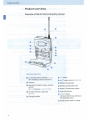
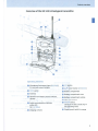
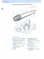
Overview of the EK 100 G3 diversity receiver
I
Operating elements
0
3.5 mm jack socket, lockable (AF OUT)
(the shielding is used by antenna II)
f) Antenna I
E) Operation and battery status indicator,
red LED
(lit= ON /flashing= LOW BATIERY)
0
0
RF signal indication, green LED
(lit= RF )
Charging contacts
0 SET button
8 A /T rocker button (UP/ DOWN )
0 Battery compartment
0 Battery compartment cover
4@ Battery compartment catches
G) Infra-red interface
(!) ON / OFF button
(serves as the ESC (cancel) key in
the operating menu)
4i) Display panel, backlit in orange
4
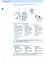
Product overviews
Overview of the SK 100 G3 bodypack transmitter
I
Operating elements
f) I" UTE switch
0
0
0
E) Antenna
4I!) Battery compartment cover
0
G) Battery compartment catches
0
9
0
Microphone/instrument input (MIC/ LINE ),
3.5 mm jack socket, lockable
Operation and battery status indicator,
red LED
(lit= ON /flashing= LOlli' BATTr;: '1 )
Audio overmodulation indicator,
yellow LED
(lit= AF PEAK )
Charging contacts
0
SET button
A / 'Y rocker button (UP/ DOWN )
Battery compartment
Infra-red interface
(i) ,. / 0 button,
serves as the ESC (cancel) key in
the operating menu
4!) Display panel, backlit in orange
5
Product overviews
Overview of the SKM 100 G3 radio microphone
I
I
SET~
UP
DOWN
Operating elements
0
Microphone head (interchangeable)
f) Name and pick-up pattern of the
microphone head (not visible here)
E) Body of radio microphone
0
Battery compartment (not visible from
outside)
0
Display panel, backlit in orange
(:) Infra-red interface
f) Antenna
6
0
Color-coded protection ring;
available in different colors
0
Operation and battery status indicator,
red LED
(lit= ON/flashing= LOW BATTERY)
4Ii) Charging contacts
4D Multi-function switch:
..- ( DOWN), .6 (UP) and • (S
E) ON/ OFF button,
serves as the ESC (cancel) key in the
operating menu
Product overviews
Overview of the SKP 100 G3 plug-on transmitter
Operating elements
0
Microphone input, XLR- 3 socket
(female, unbalanced)
8
E) Mechanical locking ring of
XLR-3 socket
Operation and battery status indicator,
red LED
(lit= · /flashing = .OW BAITER ()
0 m I r button
(serves as the ESC (cancel) key in the
operating menu)
E) Infra-red interface
0
Display panel, backlit in orange
0
0
0
UP button ( .A)
«<!) SE r button
DOWN button (T )
CD
MUT switch
Battery compartment cover
7
Product overviews
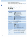
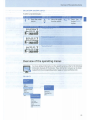
Overview of the displays of the EK 100 G3
After switch-on, the diversity receiver displays the standard display " Frequency/Name".
For further illustrations and examples of the different standard displays, refer to page 22.
I
The display backlighting is automatically reduced after approx. 20 seconds.
~~
<\r~
w100 ~; ~
m·~33I7s~Hz
2
fil
RF
p lmffiiOCn~
Display
Meaning
Diversity display:
Q) RF level "RF"
(Radio Frequency)
0][ Antenna input I is active
I ffi Antenna input II is active
RF signal level:
Field strength of t he received signal
Squelch t hreshold level
®
Modulation of the transmitter
Peak hold function
When the display shows full deflection, t he audio
input level is excessively high.
Audio level " AF"
(Audio Frequency)
I
AF
C
Frequency
Current receiving frequency
.: Name
Freely selectable name of the receiver
~
Lock mode is activated
-~
Lock mode icon
\" Battery status
Charge status:
I••••
approx. 100%
Ill:)
approx. 70%
II:)
approx. 30%
c::::J _
_ ,,/
/,,
(J" Muting function
"Mur "
or
(§
8
Charge status is critical; in addition,
the red o · B '\ 1 LED E) is fla shing.
" standard
" t · u"e" is only displayed on the " r q n1 "INa
received.
being
is
signal
RF
no
when
22)
page
(see
display
The diversity receiver then does not output an audio signal.
line output level
The line output level A ou- is only displayed on the
n 1e ·1ar " standard display
"r t1. en1 1
(see page 22) .
Pilot t one " ~ "
Act ivated pilot tone evaluation
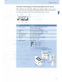
Product overviews
Overview of the displays of the SK 100/SKM 100/ SKP 100 G3
After switch-on, the transmitter displays the standard display " Frequency Name".
For further illustrations and examples of the different standard displays, refer to page 22 .
I
The display backlighting is automatically reduced after approx. 20 seconds.
!@
(i)
~
~
3~.8 75 MHz 'i' fl
a
•• w100G3
!
p
~
rml;I3~
ch
®
Display
Meaning
(i) Audio level " AF"
Modulation of the SK/SKM/SKP 100 G3
with peak hold function.
(j' Frequency
Current transmission frequency
~
(.6
Name
Freely selectable name of the transmitter
Transmission icon
RF signal is being t ransmitted
Lock mode icon
Lock mode is activated
Pilot t one " "
Pilot tone transmission is activated
It
Audio signal is muted
<
~
(
(!
'E"
Battery status
Charge stat us:
~
approx. 100%
Ill:}
II:)
approx. 70%
1
-8 "
/
approx. 30%
Charge status is critical, the red
1 Ul.'. •iATTf f.:Y LED G/0 /0 is flashing:
9
Putting the devices into operation
Putting the devices into operation
EK 100 G3 diversity receiver
Inserting the batteries/accupack
For powering the diversity receiver, you can either use two 1.5 V AA size batteries or the
rechargeable Sennheiser BA 2015 accupack.
Open the battery compartment by pushing the two catches 4Ii) in the direction of the
arrows and open the cover
II>
II>
Insert the two batteries or the accupack as shown above. Please observe correct polarity
when inserting the batteries/accupack.
Close the battery compartment by pressing on the center of the cover €).
The battery compartment cover G locks into place with an audible click.
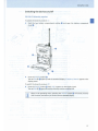
Charging the accupack
To charge the BA 2015 accupack:
II> Insert the diversity receiver into the L 2015 charger (optional accessory).
The L 2015 simultaneously charges up to two devices, e.g. two diversity receivers or
one diversity receiver and one SK 100 G3 bodypack transmitter.
The L 2015 charger can only charge the BA 2015 accupack. Standard batteries
(primary cells) or individual rechargeable battery cells cannot be charged.
10
Putting the devices into operation
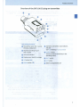
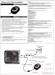
Mounting the diversity receiver to a camera
Use the supplied CA 2 camera adapter to mount the receiver to a camera's flash mount.
.,_
Determine where on the perforated plate 49 the flash mount adapter ~ will need to be
fastened so that the receiver can best be attached to the camera .
.,_
At this position, place a square nut 49 under the perforated plate 4D.
.,_
Fasten the flash mount adapter ~ to the perforated plat e 49 using the square nut
.,_
Lift one side of the belt clip 0 as shown .
.,_
Press down the belt clip 0 at one fixing point and pull it out of the receiver housing .
.,_
Repeat for the other side .
.,_
Place the perforated
•
Reinsert the belt clip f) .
.,_
Use one of the supplied line cables to connect the line input of the camera to the
socket G.
[!]
plate ~
49 .
onto the rear of the receiver.
The shield of the line cable serves as the antenna for the second diversity section.
11
Putting t he devices into operation
SK 100 G3 bodypack transmitter
Inserting the batteries/accupack/Charging the accupack
The procedure is the same as for the EK 100 G3 diversity receiver:
To insert the batteries/accupack:
~
Read the chapter "Inserting the batteries/accupack" on page 10.
To charge the accupack:
~
Read the chapter "Charging the accupack" on page 10.
Connecting the microphone cable/ line cable
The audio input is designed for the connection of condenser microphones. DC powering of the
condenser microphones is via the audio input MIC/ LINE 0 (3.5 mm jack socket).
~ Use one of the recommended Sennheiser microphones or the optional CL 2 line cable.
~
~
.,..
Connect the 3.5 mm jack plug 4» from the Sennheiser cable to the 3.5 mm jack socket
MIC/ LINE Q .
Lock the 3.5 mm jack plug by screwing down the coupling ring ~ of the cable.
Via the operating menu, adjust the sensitivity of the microphone/line input.
Attaching and positioning the corresponding microphones
ME 2/ ME 4
~
Use the microphone clip f) to attach the microphone to clothing (e.g. tie, lapel).
The ME 2 clip-on microphone (shown on the right in the diagram) has an omni-directional
pick-up pattern. It is therefore not necessary to position it precisely.
~ Attach the ME 2 microphone as close as possible to the sound source.
The ME 4 clip-on microphone (shown on the left in the diagram) has a cardioid pick-up
pattern.
Position the ME 4 microphone so that its sound inlet is directed towards the sound source
~
(e.g. mouth).
12
Putting t he devices into operation
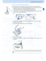
Attaching the bodypack transmitter to clothing
You can use the belt clip 49 to attach the bodypack transmitter to clothing (e.g. belt, waistband).
The belt clip is detachable so that you can also attach the transmitter with the antenna
pointing downwards. To do so, withdraw the belt clip 49 from its fixing points and attach it
the other way round. The belt clip 49 is secured so that it cannot slide out of its fixing points
accidentally.
To detach the belt clip:
..,.
..,.
Lift one side of the belt clip as shown in the diagram on the right-hand side .
Press down the belt clip at one fixing point and pull it out of the transmitter housing .
..,.
Repeat for the other side.
SKM 100 G3 radio microphone
..,.
Only hold the radio microphone by its body.
If you touch the antenna of the radio microphone during operation, the transmitter's range will be considerably reduced!
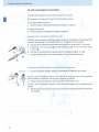
Inserting the batteries/accupack
For powering the radio microphone, you can either use two 1.5 V AA size batteries or the
rechargeable Sennheiser BA 2015 accupack.
....
Unscrew the lower part of the radio microphone from the radio microphone's body Q by
turning it counterclockwise.
When unscrewing the radio microphone during operation, the muting function is
automatically activated. " MUTE" appears on the display panel.
When screwing the lower part of the radio microphone back to the radio microphone's body, the muting is canceled .
..,.
Slide back the lower part of the radio microphone as far as it will go .
..,.
Open the battery compartment cover CE) (see page 14) .
..,.
Insert the batteries or the BA 2015 accupack as shown on the battery compartment
cover. Observe correct polarity when inserting the batteries/accupack (see page 14).
13
Putting the devices into operation
..,_
Close the battery compartment cover 6).
..,_
Push the battery compartment into the radio microphone's body .
..,_
Screw the lower part of the radio microphone back to the radio microphone's body.
Charging the accupack
To charge the radio microphone with the BA 2015 accupack (optional accessory) installed:
..,_
Use the LA 2 charging adapter to insert the radio microphone into the l 2015 charger
(charger and charging adapter are available as optional accessories).
Changing the microphone head
The microphon-e head 0 is easy to charnge.
..,_
Unscrew the microphone head 0
.
Do not touch the contacts of the radio microphone nor the contacts of the microphone head 0 . The contacts can become dirty or damaged if touched.
When unscrewing the microphone head O during operation, the muting function is
automatically activated. " MUTE" appears on the display panel.
When screwing the microphone head
is canceled .
..,_
14
0
back to the radio microphone, the muting
Screw the desired microphone head to the radio microphone.
The radio microphone is operational again.
Putting the devices into operation
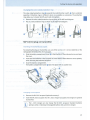
Changing the color-coded protection ring
The color-coded protection ring «l) prevents the multi-function switch {D from accidental
operation. Protection rings in different colors are available as accessories. The protection
rings allow you to clearly identify each radio microphone .
.,..
Remove the color-coded protection ring as shown in the left-hand diagram .
.,..
Put on a new protection ring as shown in the right-hand diagram.
SKP 100 G3 plug-on transmitter
Inserting the batteries/accupack
For powering the plug-on transmitter, you can either use two 1.5 V AA size batteries or the
rechargeable Sen nheiser BA 2015 accupack.
.,..
Slide the battery compartment cover G) in the direction of the embossed arrow and open
the cover.
.,..
Insert the two batteries or the accupack as shown below. Please observe correct polarity
when inserting the batteries/accupack.
.,..
Close the battery compartment.
The battery compartment cover {D locks into place With an audible click.
Charging the accupack
.,.. Remove the BA 2015 accupack (optional accessory) .
.,..
Insert the BA 2015 accupack into the L 2015 charger (accupack and charger are optional
accessories):
m
~
The L 2015 charger can only clrlarge the BA 2015 accupack. Standard batteries
(primary cells) or individual rechargeable battery cells cannot be charged.
15
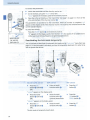
Using the devices
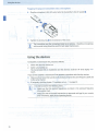
Plugging the plug-on transmitter onto a microphone
Ill>
Plug the microphone's XLR-3M socket onto the transmitter's XLR-3F socket 0
Ill>
Tighten the locking ring f) in the di rection of the arrow.
m
l...:!J
.
The transmitter uses the microphone body as an antenna - therefore microphones
with a metal casing should be used for best signal transmission.
Using the devices
To establish a transmission link, proceed as follows:
1.
Switch the diversity receiver on.
2.
Switch a transmitter on.
The transmission link is established and the diversity receiver's RF level display " RF"
reacts.
If you cannot establish a transmission link between transmitter and diversity receiver:
Ill> Make sure that transmitter and diversity receiver are set to the same frequency bank and
to the same channel.
.,. If necessary, read the chapter "If a problem occurs ... " on page 29.
It is vital to observe the following notes:
.,.
Ill>
16
Make sure that the desired frequencies are listed in the enclosed frequency
information sheet.
Make sure that the desired frequencies are approved and lega l in your country
and, if necessary, apply for an operating license.
Using the devices
Switching the devices on/ off
EK 100 G3 diversity receiver
To switch the diversity receiver on :
.,..
Push the two battery compartment catches (i) and open the battery compartment
cover f) .
.,..
Press the ON/ OFF button 0 .
The red ON LED f) lights up and the standard display " Frequency/Name" appears on the
display panel.
To switch the diversity receiver off:
.,..
Press the ON/ OFF button 0 untii"OFF" appears on the display panel.
The red ON LED f) goes off and the diversity receiver switches off.
f!l
~
When in the operating menu, pressing the ON/ OFF button 0 will cancel your entry
(ESC function) and return you to the current standard display.
17
Using the devices
SK 100 G3 body pack transmitter, SKM 100 G3 radio microphone and
SKP 100 G3 plug-on transmitter
4
To switch your transmitter
(online operation) :
SK 100 G3
SKM 100 G3
•
...
Push the two catches CD •
and open the battery
compartment cover 4Ii).
Briefly press the ~/ r
button G). The bodypack
transmitter transmits an
RF signal.
lights
The red ON LED
up and the standard
display " reo
1e" appears on the
display panel. The transmission icon (1) is
displayed.
SKP 100 G3
Briefly press the ON/ OfF •
button (D.
The radio microphone
transmits an RF signal.
The red ON LED 0 lights
up and the standard
display " rrequency/
N. me" appears on the
display panel. The transis
mission icon
displayed.
Briefly press the ON/ OFF
button ().
The plug-on transmitter
transmits an RF signal.
The red ON LED G lights
up and the standard
display " Frequency I
Name" appears on the
display panel. The transis
mission icon
displayed.
You can switch your transmitter on and deactivate the RF signal on switch-on.
For more information. refer to page 19.
To switch your transmitter off:
•
•
If necessary, deactivate the lock mode (see page 20).
..,. Press the ~ I ..
Press the ON/ " F
button 0 until " OFr"
button 4» until "
on the display
display
the
appears
on
appears
panel.
panel.
The display panel turns
The display panel turns
off. The red ON LED 0
off. The red ON LED 0
goes off.
goes off.
..,.
Press the O~/ r11
button 9 until 11
appears on the display
panel.
The display panel turns
off. The red ON LED Q
goes off.
When in the operating menu. pressing the or / 0 button will cancel your entry
{ESC function) and return you to the current standard display.
18
Using the devices
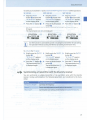
To switch your transmitter on and to deactivate the RF signal on switch-on (offline operation):
SK 100 G3
SKM 100 G3
SKP 100 G3
....
Keep the ON/ OFF
button @) pressed until
" RF Mute On 7 " appears
on the display panel.
....
....
Keep the ON/ OFF
button 9 pressed until
" RF Mute On?" appears
on the display panel.
....
Press the SET button f).
.... Press the multi-function
switch G).
..,..
Press the SET button
Keep the ON/ OFF
button 0 pressed until
" RF Mute On?" appears
on the display panel.
4ID.
The transmission frequency is displayed but the transmitter does not transmit an
RF signal.
The transmission icon @ is not displayed.
33.875MHz -@
- ew100G3
! 1:p
533.875MHz -@
a
- ew100G3
limml•··~
!
p
33.875MHz -@
a
- ew100G3
! 1:p
l!!ml•··~
a
limml•··~
Use this function to save battery power or to prepare a transmitter for use during
live operation without causing interference to existing transmission links.
To activate the RF signal:
sy+
....
Briefly press the ON/ OFF
button @).
" RF Mute Off" appears
on the display panel.
....
Briefly press the ON/ OFF
button (!).
" RF Mute Off" appears
on the display panel.
..,..
Briefly press the ON/ OFF
button 0 .
" RF Mute Off" appears
on the display panel.
....
Press the SET button f). ....
The transmission icon @)
is displayed again.
Press the multi-function
switch CD.
The transmission icon @
is displayed again.
..,..
Press the SET button 4ID.
The transmission icon @
is displayed again.
Synchronizing a transmitter with the diversity receiver
You can synchronize a suitable transmitter of the ew 100 G3 series with the diversity
receiver. During synchronization, the following parameters are transferred to the transmitter:
Setting
Transferred parameters
" Frequency Preset"
Currently set frequency
" Nar1e"
Freely selectable name currently set on the receiver
" Pilot Tone"
Current pilot tone setting of the receiver (" Inactive"/" Act ive" )
19
Using the devices
To transfer the parameters:
Switch the transmitter and the diversity receiver on.
On the receiver, call up the " Sync" menu item.
" ync" appears on the display panel of the diversity receiver.
Place the infra-red interface of the transmitter (see page 5 to page 7) in front of the
infra-red Interface of the diversity receiver 4]).
•
•
•
The parameters are transferred to the transmitter. When the transfer is completed, ".J"
appears on the display panel of the diversity receiver. The receiver then switches back to the
current standard display.
To cancel the transfer:
Press the ON/OFf button 0 on the diversity receiver.
"X" appears on the display panel of the receiver. "X" also appears if no suitable transmitter was found (wrong frequency range/wrong generation) .
EK 10 0 G3
./
SKM 100 G3
SK 100 G3
SKP 100 G3
Deactivating the lock mode t emporarily
You can activate or deactivate the automatic lock mode via the " Au Lo k" menu item (see
page 23) . If the lock mode is activated, you have to temporarily deactivate it In order to be
able to operate the devices:
EK 100 G3/SK 100 G3
..,.
" 01
•
Press the SET
button 0 (EK) or f)
(SK).
SKM 100 G3
..,.
Press the multifunction switch 4]).
SKP 100 G3
....
Press the Sn
button 4I!).
•
Press the
UP button 0 /
DOWN button 0
e 1" appears on the display panel.
Press the rocker
button f) (EK) or 0
(SK).
•
Move the multifunction switch 4])
upwards/downwards.
" Unlock?" appears on the display panel.
..,.
Press the SET
button 0 (EK) or f)
(SK).
•
Press the multifunction switch 4]).
The lock mode is temporarily deactivated.
20
..,.
Press the SET
button
e.
.
Using t he devices
How you are using the devices determines how long the lock mode remains deactivat ed :
The lock mode remains deactivat ed until you exit the operating menu.
When one of the standard displays is shown
The lock mode is automat ically activated after 10 seconds.
The lock mode icon flashes prior to the lock mode being activated again.
Muting the audio signal or deactivating the RF signal
You can deactivate the RF signal of the t ransmitters (SKM 100 G3, SK 100 G3,
SKP 100 G3) on switch-on. For more information, refer to the chapter " Switching the
devices on/off" on page 17.
Using t he ON/ OFF button, you can also activate/deactivate the transmitters' RF
signal during operation. To do so, briefly press the ON/ OFF button and proceed as
described on page 19.
SK 100 G3/SKP 100 G3
533.875MHz
- ew100G3 6
!P rmr~···~
The MUTE swit ch 8 (SK)/ f) (SKP) allows you to mute the audio signal or to deactivate the
RF signal. Via the " Mute Mode" menu item, you can set the desired function of the MUTE
switch 8 (SK)/ f) (SKP):
Setting
Slide the MUTE switch 8 I
" AF On/Off"
... to t he left (position MUT[)
Mutes the audio signal
... t o t he right
Unmutes t he audio signal
... to the left (position
Deactivates the RF signal
(offline operation)
... t o t he right
Activates t he RF signal
(online operation)
,
" Disabled"
0 ...
Function
No f unction
..,.
From the " Mute Mode" menu item, select the desired setting (see page 25 ) .
..,.
Exit t he operating menu.
...
Slide the MUTE switch 8 (SK)/ 0 (SKP) to the left, to the position MUTE.
The transmitter reacts as indicated in the table.
21
Using the devices
The current state of the muting function or the RF signal is displayed on the display panel of
the transmitter:
Audio signal is muted
Transmitter's display panel:
" MUTE" <V is displayed
Audio signal is activated (muting is canceled)
Transmitter's display panel:
" MUTE" <V is not displayed
RF signal is deactivated
Transmission icon @ is not displayed,
" MUTE" <V is displayed
Transmitter's display panel:
RF signal is activated
Transmission icon @ is displayed,
" MUTE" <V is not displayed
Transmitter's display panel:
Selecting a standard display
EK 100 G3
ON /OFF
~
Briefly press the ON/ OFF button to select a standard display.
~
Contents of the display
533.875MHz
l&ew100G3
RF AF p Mllii3 ~··•I
I
I
li
RF AF
22
a
B.Ch: 20.12
ew100G3
p Q ~··•I
a
Selectable standard display
" Frequency /Name"
with " MUTE" display Q)
with display of t he line output level " :. f C , JT "
.·
Overview of the operating menus
SK 100/SKM 100/SKP 100 G3
To select a standard display:
SK 100 G3
A
SKM 100 G3
..,. Press the rocker
~
button.
Contents of the display
-
!
~
33.875 M Hz ,_.
p
Move the multifunction switch.
~A
..,.
Press the UP
button/DOWN
button.
Selectable standard display
" Frequency /Name"
p
"Channei/Frequency"
l&llii31••·~
ew100 G3 ,..
- B.Ch: 20.12 6
!
...
..,.
w 100 G3 6
P 1Miii31•••~
B.Ch: 20.12 ,_.
- 533.875MHz6
!
.&
0
SKP 100 G3
" Name/Channel"
h'J0ii31••·~
Overview of the operating menus
For more detailed information on the operating menus, refer to the individual
instruction manuals of the devices. These instruction manuals can be downloaded from the corresponding product pages at www.sennheiser.com.
EK 100 G3
Main menu
"Menu"
Sync
Squelch
"Easy Setup"
Frequency Preset
Name
AFOut
Auto Lock
Exit
Extended menu
"Advanced Menu"
Reset List
Current List
Scan New List
Exit
Tune
Pilot Tone
LCD Contrast
Reset
Software Revision
Exit
23
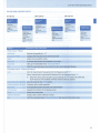
Overview of the operating menus
When one of the standard displays is shown on the display panel, you can get into the main
menu by pressing the SET button 0 The extended menu" Advanced Menu" and the " Easy
Setup" menu can be accessed via the corresponding menu items.
Display
Function of the menu item
Main menu "Menu"
Sync
Synchronizes a transmitter with the diversity receiver
Squelch
Adjusts the squelch threshold
Adjustment range:"
","
",II
",can be switched off
Special function (for servicing purposes only): With the squelch threshold set to II
"
you switch the squelch off by keeping the
rocker button
pressed for 3 seconds.
If you then press the l button , you switch the squelch on again.
Easy Setup
Scans for unused frequency presets, releases and selects frequency presets
Frequency Preset
Changes the frequency bank and the channel
Name
Enters a freely selectable name
Adjusts the audio output level
Adjustment range: -30 dB to +12 dB, adjustable in steps of 6 dB
Auto lock
Activates/deactivates the automatic lock mode
Calls up the extended menu "
"
Exits the operating menu and returns to the current standard display
"Easy Setup"
Reset list
Releases all locked frequency presets
Selects an unused frequency preset
Scan New List
Automatically scans for unused receiving frequencies (frequency preset scan)
Exits the menu "
, -~
" menu and returns to the main menu
Extended menu "Advanced Menu"
Tune
Sets the receiving frequencies for the frequency bank " U11
Sets a channel and a receiving frequency for the frequency bank 11 U":
IJII..
Select this menu item and call it up by pressing the SE button 0 until the channel
selection appears.
Activates/deactivates the pilot tone evaluation
LCD Contrast
Adjusts the contrast of the display panel
Resets the diversity receiver
Displays the current software revision
Exits the extended menu "
24
" and returns to the main menu
Overview of the operating menus
SK 100/SKM 100/SKP 100 G3
Main menu
"Menu"
Sensitivity
Frequency Preset
Name
Auto lock
Exit
SKP 100 G3
SKM 100 G3
SK 100 G3
Extended menu
"Advanced Menu"
Tune
Mute Mode
Cable Emulation
Pilot Tone
LCD Contrast
Reset
Software Revision
Main menu
"Menu"
Main menu
"Menu"
Sensitivity
Frequency Preset
Name
Auto Lock
Sensitivity
Frequency Preset
Name
Auto Lock
_f
Exit
Extended menu
"Advanced Menu"
Tune
Pilot Tone
LCD Contrast
Reset
Software Revision
Exit
I
_I
Exit
Extended menu
"Advanced Menu"
Tune
Mute Mode
Pilot Tone
LCD Contrast
Reset
Software Revision
Exit
Exit
Display
Function of the menu item
Main menu "Menu"
Sensitivity
Adjust s the sensitivity" AF"
Frequency Preset
Changes the frequency bank and the channel
Name
Enters the transmitter name
Auto Lock
Activates/deactivates the automatic lock mode
Advanced
Calls up the extended menu " Advanced Menu"
Fxit
Exits the operating menu and returns to the current standard display
Extended menu "Advanced Menu"
Tune
Sets the transmission frequencies for the frequency bank " U"
Sets a channel and a transmission frequency for the frequency bank" U"
..,.
Select this menu item and call it up by pressing the SET button (SK, SKP)/the
multi-function switch (SKM) until the channel selection appears.
Mute Mode (SK, SKP only 1 Sets the mode for the .~1UT £switch
Cable Emulation (SK only) Emulates guitar cable capacities
Activates/ deactivates the pilot tone transmission
LCD Contrast
Adjusts the contrast of the display panel
Reset
Resets the transmitter
Software Revision
Displays the current software revision
Exits the extended menu " Advanced Menu" and returns to the main menu
25
Synchronizing transmitters with diversity receivers
Synchronizing t ransmitters with diversity receivers
When synchronizing transmitters with diversity receivers, please observe the following:
..,.
Make sure that the desired frequencies are listed in the enclosed frequency
information sheet.
OR:
..,.
..,.
Contact your Sennheiser partner who will be pleased to calculate intermodulation-free frequencies for you .
Make sure that the desired frequencies are approved and legal in your country
and, if necessary, apply for an operating license.
Upon delivery, transmitter and diversity receiver are synchronized with each other. If,
however, you cannot establish a transmission link between transmitter and diversity
receiver, you have to synchronize the channels of the devices:
..,. Deactivate the RF signal on all transmitters (see page 21) .
This prevents that, during the frequency scan, the channels used by switched-on transmitters are displayed as "used".
..,. With a diversity receiver, perform a frequency preset scan to scan the frequency banks
for unused channels ("Scan New Ltst", see page 24) .
..,. Select a frequency bank and a channel on this diversity receiver ("Current List", see
..,.
page 24).
If you want to set up a multi-channel system, select a frequency bank with a sufficient
number of unused channels for all planned transmission links.
Synchronize a transmitter with the diversity receiver (see page 19).
The receiver's frequency, name and pilot tone setting are transferred to the transmitter.
OR:
..,.
..,.
Manually set the transmitter to the same frequency bank and channel that you set on the
receiver.
Activate the RF signal on the transmitter.
The transmission link is established.
If you want to set up a multi-channel system:
..,. Repeat the following 4 steps for each additional transmission link:
- Perform a frequency preset scan with the next diversity receiver.
- Select a channel from the same frequency bank as with the first diversity receiver.
- Synchronize a transmitter with the diversity receiver.
- Activate the RF signal on the transmitter.
26
Synchronizing transmitters with diversit y receivers
Using freely selectable frequencies
You can also freely select the receiving frequencies and store these f requencies in the
frequency banks " U".
It might be t hat t he f reely selected frequencies are not intermodulat ion-f ree
If you use frequencies from the frequency bank " •", it might be that the frequencies are not intermodulation-free.
•
Contact your Sennheiser partner who will be pleased to calculate intermodulation-free frequencies for you (see www.sennheiser.com).
~
Set each diversity receiver to the frequency bank " U" .
.-
On one of t he receivers, select a channel within this frequency bank and assign this
channel one of the calculated receiving frequencies ("Tune" , see page 24 ).
•
Synchronize a transmitter with this receiver (see page 19).
OR:
•
Manually set the transmitter to the same frequency bank and channel that you set on the
receiver.
•
Repeat for the remaining transmitters and receivers as described above.
27
I
Cleaning the devices
Cleaning the devices
CAUTION!
liquids can damage the electronics of the devices!
Liquids entering the housing of the devices can cause a short-circuit and damage the
electronics .
..,..
Keep all liquids away from the devices .
..,..
Use a cloth to clean the devices from time to time. Do not use any solvents or cleansing
agents.
SKM 100 G3
To clean the radio microphone's sound inlet basket:
..,..
CAUTION!
Unscrew the upper sound inlet basket from the microphone head by turning it counterclockwise.
Liquids can damage t he microphone head!
Liquids can damage the microphone head .
..,..
Only clean the upper sound inlet basket .
..,..
Remove the foam insert.
..,..
There are two ways to clean the sound inlet basket:
- Use a cloth to clean the upper sound inlet basket from the inside and outside
- or scrub with a brush and rinse with clear water.
..,..
If necessary, clean the foam insert with a mild detergent or replace the foam insert .
..,..
Dry the upper sound inlet basket .
..,..
Dry the foam insert.
..,..
Reinsert the foam insert .
..,..
Replace the sound inlet basket on the microphone head and screw it tight.
You should also clean the contact rings of the microphone head from time to time:
..,..
28
Wipe the contact rings of the microphone head with a cloth.
If a problem occurs ...
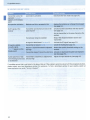
If a problem occurs ...
EK 100 G3
I
Problem
Possible cause
Possible solution
Diversity receiver cannot
be operated, " Locked"
appears on the display
panel
Lock mode is activated
Deactivate the lock mode (see page 20).
No operation indication
Batteries are flat or accupack is flat
Replace the batteries or recharge the accupack
(see page 10).
No RF signal
Transmitter and receiver are not on the
same channel
Set the transmitter and receiver to the same
channel.
Synchronize the transmitter with the receiver
(see page 19).
RF signal available, no
audio signal, " :", 1, J ~E "
appears on the display
panel
Transmission range is exceeded
Reduce the distance between receiver and
transmitter.
RF signal is deactivated ("RF Mute")
Activate the RF signal (see page 21).
Transmitter is muted
Cancel the muting (see page 21).
Receiver's squelch threshold is adjusted
too high
Reduce the squelch threshold setting on the
receiver (see page 24).
Transmitter doesn't transmit a pilot tone Deactivate the pilot tone evaluation
(see page 24).
Transmitter sensitivity is adjusted too
Audio signal has a high
level of background noise low
Adjust the transmitter sensitivity correctly
("SensrtiVIty", see page 25).
Audio signal is distorted
Transmitter sensitivity is adjusted too
high
Adjust the transmitter sensitivity correctly
("<:;~~, , •. , t~,- ",seepage25).
Receiver's audio output level is adjusted
too high
Reduce the audio output level (" A· uu·", see
page 24).
No access to a certain
channel
During scanning, an RF signal has been
Set the transmitter operating on this channel to
detected on this channel and the channel a different channel and redo the frequency
has been locked
preset scan (see page 24).
Switch the transmitter off and redo the
During scanning, a transmitter of your
system operating on this channel has not frequency preset scan (see page 24).
been switched off
29
If a problem occurs ...
SK 100/SKM 100/SKP 100 G3
Problem
Possible cause
Possible solution
Transmitter cannot be
"
operated, "
appears on the display
panel
Lock mode is activated
Deactivate the lock mode (see page 20).
No operation Indication
Batteries are flat or accupack is flat
Replace the batteries or recharge the accupack
(see page 13).
No RF signal at the
receiver
Transmitter and receiver are not on the
same channel
Synchronize the transmitter with the receiver
(see page 19).
Set the transmitter to the same channel as the
receiver.
Transmission range is exceeded
M ..")
RF signal is deactivated ("
)
RF signal available,
no audio signal,
" appears on the
display panel
Transmitter Is muted (
Audio signal has a high
level of background noise
or is distorted
Transmitter's sensitivity is adjusted too
low/too high
Receiver's squelch threshold Is adjusted
too high
Reduce the distance between receiver and
transmitter.
Activate the RF signal (see page 21) .
cancel the muting (see page 21).
Reduce the squelch threshold setting on the
receiver.
Transmitter doesn't transmit a pilot tone Activate or deactivate the pilot tone transmission (see page 25).
Adjust the input sensitivity (see page 25).
If a problem occurs that is not listed In the above table or if the problem cannot be solved with the proposed solutions,
please contact your local Sennheiser partner for assistance. To find a Sennheiser partner in your country, search at
www.sennheiser.com under "Service & Support".
30
Specifications
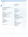
Specifications
System
Modulation
Frequency ranges
Frequencies
Switching bandwidth
Frequency stability
Compander system
Nominal/peak deviation
Pilot tone (frequency/deviation)
THO
Temperature range
I
wideband FM
516-558,566-608,626-668,734-776,
780-822, 823-865 MHz (A toE, G, see page 3)
1,680 frequencies, tuneable in steps of 25kHz
20 frequency banks, each with up to 12 factory-preset
channels
1 frequency bank with up to 12 user programmable
channels
42 MHZ
±10 ppm (-10°Cto +55°C)
Sennheiser HDX
±24 kHz/±48 kHz
32.7665 kHz/±2 kHz
~0.9%
EK 100 G3
Receiver principle
Sensitivity
(with HOX, peak deviation)
Adjacent channel rejection
lntermodulation attenuation
Blocking
Squelch
Pilot tone squelch
S/N ratio (1 mV, peak deviation)
AF output voltage
(at peak deviation, 1 kHz AF)
Adjustment range of audio output level (" AF Out")
Power supply
Nominal voltage
Power consumption:
adaptive diversity
< 1.6 ~V for 52 dBArms S/N
typ.;::: 65 dB
typ.;::: 65 dB
;::: 70 dB
Off, Low: 5 dB!!V, Middle: 15 dB!!V, High: 25 dB!!V
can be switched off
;::: 60 dB
3.5 mm jack socket:+ 11 dBu (mono, unbalanced)
42 dB, adjustable in steps of 6 dB
2 AA size batteries, 1.5 V or BA 2015 accupack
2.4V---
• at nominal voltage
typ.140 mA
• with switched-off diversity receiver
Operating time
Dimensions
Weight (incl. batteries)
~ 25 IJA
typ. 8 hrs
approx. 82 x 64 x 24 mm
approx. 120 g
In compliance with
Europe
( E EMC
Radio
Security
USA
EN 301489-1/-9
EN 300422-1/-2
EN 60065
~ 47 CFR 15 subpart B
31
Specifications
Approved by
Canada
Industry Canada RSS 123
IC 2099A-G3EK100
limited to 806 MHz
SK 100/SKM 100/SKP 100 G3
RF output power at so n
Pilot tone squelch
AF frequency response
SK
SKM/SKP
Signal-to-noise ratio (1 mV RF, peak deviation)
SK/ SKM/SKP
Max. input voltage (SK) microphone/line
Max. input voltage {SKP)
Input impedance SK microphone/line
Input impedance SKP
Input capacitance SK
Adjustment range of Input sensitivity
Power supply
Nominal voltage
Current consumption
at nominal voltage
with switched-off transmitter
Operating time
Dimensions
Weight {incl. batteries)
32
typ. 30 mW
can be switched off
microphone: 80-18,000 Hz
----------,..--line: 2S-18,000 Hz
80-18,000 Hz
~
110 dBA
3 Vrms
3.3 Vrms
40 kn. unbalanced/1 MO
60 k!l. unbalanced
switchable
SK: 60 dB, adjustable in steps of 3 dB
SKM, SKP: 48 dB, adjustable in steps of 6 dB
2 AA size batteries, 1.5 V
or BA 201S accupack
2.4 =-=-=
---------------------------------
v
typ. 180 rnA
---------------------~-$; 2S IJA
---------------~-----------------typ. 8 hrs
- -64 x 24 mm
--SK: approx. 82 x
SKM: approx. 0 SOx 265 mm
SKP: approx. 10S x 43 x 43 mm
SK: approx. 160 g
SKM: approx. 4SO g
SKP: approx. 19S g
Specifications
In compliance with (SK, SKM and SKP 100 G3)
CE
Europe
EMC
Radio
Security
EN 301489-1/-9
EN 300422-1/-2
EN 60065, EN 62311 (SAR)
Approved by (SK, SKM and SKP 100 G3)
Canada
USA
SK 100 GJ
Industry Canada RSS 123,
IC: 2099A-G3SK
limited to 806 MHz
SlM100GJ
SKP 100G3
Industry Canada RSS 123,
IC: 2099A-G3SKMEM
limited t o 806 MHz
Industry Canada RSS 123,
IC: 2099A-G3SKP
limited to 806 MHz
FCC-Part 74,
FCC-10: OMO G3SK
limited to 698 MHz
FCC-Part 74,
FCC-10: OMO G3SKMEM
limited to 698 MHz
FCC-Part 74,
FCC-10: OMOG3SKP
limited to 698 MHz
For accessories and information on connector assignment, visit the ew G3 product page at www.sennheiser.com.
Microphones (SK 100 G3)
Microphone type
condenser
condenser
Sensitivity
Pick- up pattern
20 mV/Pa
omni-directional
40 mV/Pa
cardioid
Max. SPL
130 dB SPL
120 dB SPL
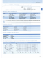
MMD 835-1 microphone head (SKM 100 G3)
MMp~~l
Microphone type
dynamic
Sensitivity
2.1 mV/Pa
Pick- up pattern
cardioid
Max. SPL
154 dB SPL
.
·
Polar diagram and frequency response curve of the MMD 835-1 microphone head (SKM 100 G3)
Polar diagram. M~D 835-~ .'
-•.•.~...·• Frequency response curve MMD 835-1
dBV
·30
-40
-
-so
1--'
,...
-··-
1000Ht-
:-/< 7 ',.
r
----- _.,_
~·w
lW
HOt"' ......
6000Hl-
l..---'
--
t-r-
\
\
y
I
,/
I
-70
-so
J I
I I
so
100
200
500
lk
2k
Sk
1ok
\
\
\
I
20k
Hz
UOOOH& -
33
Manufacturer Declarations
Manufacturer Declarations
Warranty
Sennheiser electronic GmbH & Co. KG gives a warranty of 24 months on this product.
For the current warranty conditions, please visit our web site at www.sennheiser.com or
contact your Sennheiser partner.
In compliance with the following requirements
• RoHS Directive (2002I9SIEC)
• WEEE Directive (2002I96IEC)
'Q"
A
Please dispose of these products at the end of their operational lifetime by taking
them to your local collection point or recycling center for such equipment.
• Battery Directive (2006I66IEC)
~ The supplied batteries or rechargeable batteries can be recycled. Please dispose of
A
them as special waste or return them to your specialist dealer.ln order to protect
the environment, only dispose of exhausted batteries.
CE Declaration of Conformity
• EK 100 G3: ((0682
SKI SKM I SKP 100 G3: ((0682<1>
• R&TIE Directive (1999ISIEC)
The declarations are available at www.sennheiser.com.
Before putting the devices into operation, please observe the respective country-specific
regulations.
34
Manufacturer Declarations
Statements regarding FCC and Industry Canada
These devices comply with Part 15 of the FCC Rules and with RSS-210 of Industry Canada.
Operation is subject to the following two conditions: (1) these devices may not cause harmful
interference, and (2) these devices must accept any interference received, including interterence that may cause undesired operation.
This equipment has been tested and found to comply with the limits for a Class B digital
device, pursuant to Part 15 of the FCC Rules. These limits are designed to provide reasonable
protection against harmful interference in a residential installation. This equipment generates, uses and can radiate radio frequency energy and, if not installed and used in accordance
with the instructions, may cause harmful interference to radio communications. However,
there is no guarantee that interference will not occur in a particular installation. If this equipment does cause harmful interference to radio or television reception, which can be determined by turning the equipment off and on, the user is encouraged to try to correct the interference by one or more of the following measures:
• Reorient or relocate the receiving antenna.
• Increase the separation between the equipment and receiver.
• Connect the equipment into an outlet on a circuit different from that to which the receiver
is connected.
• Consult the dealer or an experienced radio/TV technician for help.
These class B digital devices comply with the Canadian ICES-003.
Changes or modifications made to this equipment not expressly approved by Sennheiser
electronic Corp. may void the FCC authorization to operate this equipment.
Before putting the devices into operation, please observe the respective country-specific
regulations!
35
I
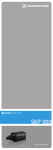
Cvolutionwireless@ QUICK START GUIDE
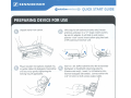
Unpack items from carton.
(This step for EM rackmount units only) Attach
antennas and place in a "V" shape. Insert country
tip into AC adapter, it will slide in and make a
positive "click" sound. Insert yellow plug into back
of EM rackmount receiver unit.
Plug in lavalier microphone, headset mic,
or guitar cable into bodypack transmitter
and secure by gently tightening the
locking ring (if applicable).
Insert 2 x AA (UM3) batteries into the transmitter
(bodypack or handheld), observing polarity.
(Camera sets only): Insert 2 x AA batteries into
receiver bodypack (EK100G3). Connect either the
1/8" (3.5mm) or XLR camera output cable.
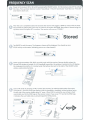
FREQUENCY SCAN
Power on the rece1ver (EM or EK umt) by pressing the ON/OFF button. On the receiver, press SET to activate
the menu. Press up/down buttons to select "Easy Setup". Press SET and choose "Scan New List." Press SET
once more to start scan.
2
1.
[Z) It:NNMEIS& R
~~
.. .
~
""".....,..,~
... .
..
.:.....
................~~
tlJStiNNHitll"
_
I~
3
___....,.."""
,
C[) I I NNH I U I "
• •
-
0
After the scan is completed (about 60 seconds) the receiver will suggest a BANK to choose with the most
free channels by placing the cursor over it. Press SET to confirm t h is BANK. Now select a channel using the
up/ down arrows and press SET to confirm. The receiver will now say "STORED."
1 ~--
3.
.. .
Stored
Tap ON/OFF to exit the menu. The frequency chosen will be displayed. You should see zero
RF/AF activity on the meter (indicating you are on a free channel).
Power up the transmitter (SK, SKM) you wish to pair with the receiver. Become familiar where the
infrared (IR) window is located. On a G3 handheld transmitter, the window is located on the LCD display.
On a body pack transmitter, it is located under the battery door just to the right of the ON/OFF button
undera purple colored window.
1.
Enter SYNC mode by pressing "SYNC" button (EM receivers) or selecting SYNC option from menu
(EK receiver). Once the SYNC logo displays, hold the handheld or bodypack infrared window facing
the left side of the receiver display about 6" away. When SYNC is successful, you will see a check
mark briefly next to the SYNC logo on t he receiver screen. If you see an "X" next to the SYNC logo,
it Indicates the sync failed and you should repeat the SYNC process.
lb.
2g..
0
~
• It is suggested that you adjust the receiver (EM or EK) AF OUT setting to around OdB for most situations.
The AF OUT setting is your master ouput voume.
• The SENSITIVITY setting (SK and SKM transmitters only) should be adjusted so that in your loudest
passages, the AF PEAK indicator briefly illuminates. As the SENSITIVITY settings move closer to "0 dB" they
become louder.
• If setting up multiple systems in the same frequency range (A/B/G), you can repeat the
"EASY SETUP /SCAN NEW LIST /SYNC" process for each system.
• Be sure to choose the same BANK number (but a different channel number) for units in the same frequency
range in order to ensure trouble-free operation.
• It is suggested you perform the EASY SETUP /SCAN NEW LIST function whenever you use your unit in a
different area (at a gig etc.) Open frequencies vary from one location to another.
• On the receiver: The RF and AF meter bars indicate status. RF (Radio Frequency) meter is akin to "bars of
reception" on your cellphone. The AF (Audio Frequency) meter moves whenever audio is transmitted
through the system .
• On portable camera sets the receiver will clip onto the included CA2 camera shoe mount.
Sennheiser Electronic Corporation
One Enterprise Drive, Old Lyme, CT 06371
Tel: (860) 434-9190 • Fax: (860) 434-1759
www .sennheiserusa.com
516-558 MHZ
[Zj SENNHEISER
Informations complementaires concernant
les systemes evolution wireless ew G3
Informacion adicional para sistemas
Sennheiser de Ia serie evolution wireless G3
Zusatzinformation fi.ir Sennheiser Systeme
der Serie evolution wireless G3
Additional information for Sennheiser
evolution wireless G3 systems
Les emetteurs et les recepteurs sont disponibles dans une plage
de frequences UHF de 42 MHz de largeur, ce qui autorise un
choix parmi 1680 frequences d'emission et de reception.
Para Ia transmisi6n se dispone de un rango de frecuencia de
42 MHz de amplitud con 1680 frecuencias de transmisi6n/
recepci6n posibles en Ia banda UHF.
FUr die Obertragung steht im UHF-Band ein 42 MHz breiter Frequenzbereich mit 1680 moglichen Sende-/Empfangsfrequenzen zur Verfilgung.
Transmitters and receivers are available in a 42 MHz UHF
frequency range with a tot al of 1,680 transmission/ receiving
frequencies.
Les emetteurs et les recepteurs possedent 20 banques de frequences, dans lesquelles chaque canal est preregle en usine sur
une frequence. Les frequences prereglees au sein d'une banque
de frequence sont compatibles entre elles, c.a.d. exemptes
d'intermodulation. Elles ne peuvent pas etre modifiees.
Los transmisores y receptores cuentan con 20 ban cos de canales
cada uno para los que se ha preajustado una f recuencia en
fabrica. Dentro de un banco de canales, los preajustes de
frecuencia se encuentran libres de intermodulaci6n entre ellos.
Estos nose pueden cambiar.
Die Sender und Empfanger verfilgen Uber jeweils 20 Kanalbanke, auf denen werkseitig eine Frequenz voreingestellt ist.
lnnerhalb einer Kanalbank sind die Frequenz-Presets untereinander intermodulationsf rei. Sie sind nicht veranderbar.
Transmitters and receivers have 20 frequency banks respect ively. Each of t he channels in the f requency banks has been
factory-preset to a frequency. The frequency presets w ithin one
f requency bank are int ermodulation-free. These frequencies
cannot be changed.
Les banques de frequences « U » (ew 100 : banque << U »,
ew 300 I ew 500 : banques << U1 >> - « U6 ») permettent de
memoriser des frequences au choix, qui peuvent etre reglees
par pas de 25kHz. II se peut que ces frequences ne soient pas
exemptes d'intermodulation.
En los bancos de canales <<U» (ew 100: banco <<U», ew 300/
ew 500: banco <<U1»-«U6») puede ajustar libremente y guardar
frecuencias a pasos de 25 kHz. Estas frecuencias pueden no
estar libres de intermodulaci6n.
Le tableau suivant dresse Ia liste des frequences preregh!!es
dans les banques de frequences (( 1 )}
20 )) :
Los preajustes de frecuencia en los bancos de canales <<1» a
<<20» se representan en Ia siguiente tabla:
• Serle ew 100 G3: les 12 premiers canaux
d'une banque
• Serle ew 100 G3:
los primeros 12 canales de cada banco
de canales
• Serle ew 300 G3 : les 24 premiers canaux
d'une banque
• Serle ew 300 G3:
los primeros 24 canales de cada banco
de canales
a ((
• Serle ew 500 G3: max. 32 canaux d'une banque
• Serle ew 500 G3:
Les parametres par detaut suivants, preregles en usine, peuvent
etre restaures a tout moment via I'option Reset:
Con Ia opci6n de menu Reset, se pueden !lamar de nuevo los
siguientes ajustes de f abrica en todo momento:
Auto Lock
Sensitivity
Auto Lock
Sensitivity
RF Power
Mute Mode
Squelch
AF Out
Equalizer
Guitar Tuner
Name
Pilot Tone
Banques « U >>
Sync Settings
Warnings
IP Address
inactif
SK
-30 dB
SKM
-18 dB
standard (ew 300, ew 500)
AF On/Off (SK: tous, SKM: 300)
low/5 dB~V
EM
+18 dB
EK
0 dB
flat
inactif (ew 100, ew 500)
nom de Ia serie
n'est pas reinitialise
ne sont pas reinitialisees
inactif (ew 300, ew 500)
actif (ew 300, ew 500)
auto-IP (ew 300, ew 500)
RF Power
Mute Mode
Squelch
AF Out
Equalizer
Guitar Tuner
Name
Pilot Tone
User Banks
Sync Settings
Warnings
IP Address
max. 32 canales de cada banco de canales
inactivo
SK
- 30 dB
SKM
-18 dB
standard (ew 300, ew 500)
AF On/Off (SK: todos, SKM: 300)
low/5 dB~V
EM
+18 dB
EK
0 dB
flat
inactivo (ew 100, ew 500)
nombre de Ia serie
no se resetea con Reset
no se resetean con Reset
inactivo (ew 300, ew 500)
activo (ew 300, ew 500)
auto-IP (ew 300, ew 500)
In den Kanalbanken , U" (ew 100: Bank ,U" , ew 300/ew 500:
Bank ,U1" - , U6") konnen Sie in 25-kHz-Schritten Frequenzen
frei einstellen und abspeichern. Diese sind unter Umstanden
nicht intermodulationsfrei.
The frequency banks "U" (ew 100: bank "U ", ew 300/ew 500:
banks "U1"-"U6" ) allow t he user to store individual f requencies which are f reely selectable in 25-kHz steps. It might be t hat
these frequencies are not intermodulation-free.
Die Frequenz-Presets in den Kanalbanken , 1" bis , 20" sind in
der folgenden Tabelle dargestellt:
The followi ng table lists t he f requency presets in t he f requency
banks " 1" t o "20":
• ew 100 G3 Serie: die ersten 12 Kanale je Kanalbank
• ew 100 G3 series: the f irst 12 channels in a f requency bank
• ew 300 G3 series: the f irst 24 channels in a f requency bank
• ew 300 G3 Serle: die ersten 24 Kanale je Kanalbank
• ew 500 G3 Serie:
max. 32 Kanale je Kanalbank
• ew 500 G3 series: max. 32 channels in a frequency bank
Folgende Werkseinstellungen sind mit dem Menilpunkt Reset
jederzeit wieder abrufbar:
The following factory-preset default settings can be recalled
any time via the Reset menu it em:
Auto Lock
Sensit ivity
Auto Lock
Sensitivity
RF Power
Mute Mode
Squelch
AF Out
Equalizer
Guitar Tuner
Name
Pilot Tone
User Banke
Sync Settings
Warnings
IP Address
inaktiv
-30 dB
SK
-18 dB
SKM
standard (ew 300, ew 500)
AF On/ Off (SK: aile, SKM: 300)
low/ 5 dB~V
EM
+18 dB
EK
0 dB
f lat
inaktiv (ew 100, ew 500)
Name der Serle
wird mit Reset nicht zurilckgesetzt
werden mit Reset nicht zurilckgesetzt
inaktiv (ew 300, ew 500)
aktiv (ew 300, ew 500)
auto-IP (ew 300, ew 500)
Sennheiser electronic GmbH &Co. KG
30900 Wedemark. Germany
www.sennheiser.com
RF Power
Mute Mode
Squelch
AF Out
Equalizer
Guitar Tuner
Name
Pilot Tone
User banks "U"
Sync Settings
Warnings
IP Address
inactive
SK
-30 dB
SKM
-18 dB
standard (ew 300, ew 500)
AF On/ Off (SK: all, SKM: 300)
low/ 5 d B~V
EM
+18 dB
EK
0 dB
flat
inactive (ew 100, ew 500)
name of the series
will not be reset
will not be reset
inactive (ew 300, ew 500)
active (ew 300, ew 500)
auto-IP (ew 300, ew 500)
Printed in USA
Publ. 02/ 09
S29683/ A01
I
Frequenzbereich
US TV-channel
Ch. 21 (512-518
Ch. 22 (518-524
Ch. 23 (524-530
Ch. 24 (530-536
Bemerkung
Note
Remarque
Nota
I
I
I
I
Frequency Range
MHz)
MHz)
MHz)
MHz)
Ch . 25
Ch. 26
Ch. 27
Ch. 28
I
Bande de frequence
I
Ran go de frecuencia
USA TVKanal22
USA TVKanal23
USA TVKanal24
USA TVKanal25
und andere
und andere
und andere
us TV-Ch. 22
US TV-Ch. 23
TV·Ch. 24
+
TV-Ch. 2S
+
516-558 MHz
EBU TV-channel
Ch. 26 (510-518 MHz)
Ch. 27 (518-526 MHz)
Ch. 28 (526-534 MHz)
(536-542 MHz)
(542-548 MHz)
(548-554 MHz)
(554-560 MHz)
und andere
A
USA TVKanal 26
und andere
USA TVKanal27
USA TVKanai2B
und andere
und andere
und 29
Belgium
Ch.2 7&29
Belgien
Kan~ile
27
Ch. 29 (534-542 MHz
Ch. 30 (542-550 MHz)
Ch. 31 (550-558 MHz)
kompletter
Arbeitsbereich (1)
kompletter
Arbeits-
+
+
US TV-Ch. 27
+
US TV-Ch. 28
+
more
more
more
more
more
more
more
Etats-Unis
canal TV 22
et autres
Etats-Unis
canal TV 23
etautres
Etats-Unis
canal TV 24
et autres
Etats-Unis
canal TV 25
et autres
Etats-Unis
canal TV 26
etautres
Etats-Unis
canal TV 27
et autres
Etats-Unis
cana l TV 28
etautres
Belgique
canaux 27
et 29
Pleine bande
(1)
Pleine bande
(2)
EE.UU.
Canal TV 22
y otros
EE.UU.
Canal TV 23
y otros
EE.UU.
Canal TV 24
yotros
EE.UU.
Canal TV 25
yotros
EE.UU .
Canal TV 26
yotros
EE.UU.
Canal TV 27
yotros
EE.UU.
Canal TV 28
yotros
aelgica
Canales 27
y 29
Rango de
trabajo
completo (1)
Rango de
trabajo
completo (2)
US
US
US TV-Ch. 26
+
Full range (1)
Bemerkung
Full range (2)
kompletter
kompletter
kompletter
kompletter
Arbeitsbereich (4)
Arbeits-
bereich (5)
Arbeitsbereich (6)
kompletter
Arbeitsbereich (7)
*ompletter
Arbeits-
Full range
(4)
Full range
(S)
Full range
Full range
Full range
(3)
(6)
(7)
(8)
Pleine
bande (3)
Pleine
bande (4)
Pleine
bande (5)
Pleine
bande (6)
Pleine
bande (7)
bereich (3)
bereich (2)
Note
Remarque
Nota
Full range
Arbeitsbereich (8)
I kompletter
Arbeitsbereich (9)
Rango de
Rango de
Ran go de
Rango de
Rango de
trabajo com- trabajo com- trabajo com- trabajo com- trabajo completo (3)
pleto (S)
pleto (6)
pleto (7)
pleto (4)
• ew 100- frei wahlbare Frequenzen
I
freely selectable frequencies
•• ew 300iew 500- frei wahl bare Frequenzen
I
I
frequences au choix
freely selectable frequencies
I
I
frecuencia s de libre elecci6n
frequences au choix
I
frecuencias de libre elecci6n
[Zj SENNHEISER
Frequenz- und Sendeleistungsubersicht
Frequency and transmission power overview
Aper~u des frequences et puissances d'emission specifiques
Overzicht van landspecifieke frequenties en zendvermogens
European Nations and her
International abbreviations
Frequency range
(MHz)
All listed countries
(not Norway)
Gesetzliche Vorgaben fUr den Einsatz von Funkmikrofonen
max. RF_power
(mW-erp.)
Individual licence
required
863-865
10
no
Austria,
Cyprus,
Greece
AT
CY
GR
470- 862
so
yes
Belgium
BE
470- 608, 608- 862
50 (20)
yes
Germany
DE
470- 606, 614- 790
50
yes
790.1- 813.9,
838.1- 861.9
so
for professional
and indoor use
->no *l
Gro6britannien
GB(UK)
854.25- 861.75
(Ch.69 mobile) •z
470- 860
so
Bever Sie lhr Funkmikrofonsystem oder andere TonUbertragungsanwendungen in Betrieb nehmen, erfragen Sie bei der zustandigen
Regulierungbehorde fUr Frequenznutzung die genauen Frequenzzuweisungen und beantragen Sie ggf. die erforderliche individuelle
Zulassung. Die folgende Tabelle gibt einen Oberblick Uber die unterschiedlichen nationalen Rahmenbedingungen und Einschrankungen.
Findet sich kein Eintrag in der Tabelle, erkundigen Sie sich bitte bei der zustandigen Regulierungsbehorde nach den aktuellen
Vorschriften.
Sender mit einer HF-Strahlungsleistung von mehr als 50 mW (erp) ,werden nicht als SRD klassifiziert und erfordern grundsatzlich eine
Zulassung. Erkundigen Sle slch in dlesem Fall bei der zustandigeQ Regulierungsbehorde nach den Nutzungsvorschriften fUr dieses
Gerat!
Diese Tabelle unterliegt einer standigen Aktualisierung.
Hinweise
DE • 1 Diese Frequenzbereiche stehen fUr professionelle Anwendungen zur VerfUgung, vergleichen Sie dazu bitte das Dokument
Vfg.91/2005 der Bundesnetzagentur (URL:http://www.bunclesnetzagentur.de/enid
/cece42 92 2d 3dfad57 349fae 7d8df42 31,0 /Frequenzordnung Allgemeinzuteilungen_9u.html)
Weitere lnformationen zu den Frequenzzuweisungen verschiedener Staaten finden Sie unter:
http:/ /www.ero.dk und http:/ /www.efis.dk/search/general
Legal requirements for the use of radiomicrophones
of the EU members & adopted nations
in the range of 470-865 MHz (ERC Recommendatioh 70-03- Short Range Devices; SRD)
•J
IT
470-854
10 & so
yes
Liechtenstein
Switzerland
Ll
470- 862
so
yes
CH
Norway
NO
800-820
20mW
790- 800 & 820- 838
-
646-759
30
RO
yes
Before using your radiomicrophone system or other assisitve listening devices you must ask the relevant wireless regulator for the exact
frequency allocation and for an individual licence. The table gives an overview of the national framework requirements and restrictions.
If there is no entry in the table, please ask the relevant wireless regulatory body relating to the location of intended use about the
current legal position.
Transmitters with a radiated RF power greater than 50 mW (erp) are not classed as a SRD and always need a licence.
In this case, ask the local wireless regulatory body relevant to the location of intended use for the rules governing the usage of the
equipment!
The table is constantly updated.
Remarks:
DE • 1 These frequency ranges are open for professional user, please see the allocation document
Vfg.91/2005 of the Bundesnetzagentur (URL:http://www.bundesnetzagentur.de/enid/
cece42922d3dfad57349fae7d8df4231,0/Frequenzordnung Allgemeinzuteilungen_9u.html)
UK • 2 Up to 14 fixed frequencies, usable all over the UK. Contact JFMG for information and licence- www.jfmg.co.uk
UK • 3 Licensed on a site-specific basis according to location. Contact JFMG for information and licence- www.jfmg.co.uk
Sennheiser electronic GmbH & Co. KG
Am Labor 1, 30900 Wedemark, Germany
Phone +49 (5130) 600 0, Fax +49 (5130) 600 300
www.sennheiser.com
I
ja
Italy
Romania
fur EU-Mitglledstaaten und angeschlossene Staaten
im Frequenzbereich von 470-865 MHz (ERC-Empfehlung 70-03- Short Range Devices; SRD)
Printed in USA
Publ. 01/09
528232 I A02
Further information on frequency allocation of the nations are available at:
http://www.ero.dk and http://www.efis.dk/search/general
I
1 Exigences legales pour !'utilisation des systemes d'emission radio
I
des pays membres de I'UE & nations affiliees
dans Ia plage de frequence de 470-865 MHz (recommandation ERC 70-03- Short Range Devices; SRD)
Avant d'utiliser votre systeme d'emission radio ou d'autres systemes de transmission audio, vous devez contacter les autorites de
regulation appropriees pour /'allocation de frequence exacte et pour une licence individuelle pour ce systeme d'emission radio. La table
donne un aper~u des dispositions et restrictions nationales. S'il n'y a pas d'entree dans Ia table, veuillez contacter les autorites de
regulation appropriees pour les dispositions legales actuelles.
Les emetteurs avec une puissance d'emission rayonnee de plus de 50 mW (erp) ne sont pas classifies en tant que appareils de faible
portee (short range devices (SRD)) et ont toujours besoin d'une licence.
Dans ce cas, veuillez contacter les autorites de regulation appropriees pour les dispositions legales concernant l'usage de cet
equipement!
Cette table est constamment mise a jour.
Especificaciones legales para Ia utilizaci6n de micr6fonos inalambricos
Antes deponer en servicio el sistema de micr6fonos inalambricos u otras aplicaciones de transmisi6 n de sonido, consulte a Ia autoridad
reguladora sabre el uso de frecuencias y las asignaciones exactas de frecuencias y, en caso necesario, solicite Ia autorizaci6n individual
que se precise. La tabla siguiente ofrece un resumen de las diferentes condiciones marco y las limitaciones nacionales. Si no encuentra
Ia entrada en Ia tabla, pregunte a las autoridades reguladoras competentes las normas actuales.
Los transmisores con una potencia de radiaci6n de RF superior a 50 mW (erp) no se clasifican como SRD y, en general, requieren una
autorizaci6n. En este caso, inf6rmese a traves de las autoridades reguladoras competentes sabre las normas de utilization para este
aparato.
Esta tabla se actualiza continuamente.
Remarques:
Notas:
DE * 1 Ces plages de frequences peuvent etre utilisees pour des applications professionnelles, voir le document Vfg.91/2005 der
Bundesnetza gentu r ( URL:http:/ / www.bundesnetzagentur.de / enid/ cece42 92 2d3dfad 57 3 4 9fae 7d8df42 31, oI
DE • 1 Estas gamas de frecuencias estan disponibles para las aplicaciones profesionales; consulte al respecto el documento Vfg.91/
2005 de Ia Agencia federal alemana de redes (URL:http:// www.bundesnetzagentur.de/enid/
cece42 9 2 2d 3d fad 57 349fae 7d 8df42 31.0 /Frequenzordn u ng Allgemeinzuteilu ngen_9u .html)
Frequenzordnung Allgemeinzuteilungen_9u.html)
Vou s trouverez plus d'informations sur /'allocation des frequences a l'adresse web:
http:// www.ero.dk und http:// www.efis.dk/ search/ genera)
I
Especlficaclones legales para el uso de micr6fonos inalambricos en estados miembro de Ia UE y estados
asociadas en el rango de frecuencla de 470- 865 MHz (recomendacl6n ERC 70-03- Short Range
Devices; SRD)
Encontrara mas informaciOn sabre las asignaciones de frecuencias de las diferentes naciones en:
http:/ /www.ero.dk y http:// www.efis.dk/ search/general
Wettelijke voorschriften voor het gebruik van draadloze microfoons
Disposizioni di Iegge per Putilizzo di radiomicrofoni
Attrlbuzlone dl frequenze per l'utilizzo di radiomicrofoni da parte degli Stati membri e degll stati assoclatl nel campo di frequenza 470-865 MHz (come da raccomandazione ERC 70-03- Short Range Devices;
SRD)
Prima di mettere in funzione il sistema con radiomicrofono o altre applicazioni per Ia transmissione audio, consultare l'autorita
responsabile dell'utilizzo delle frequenze in merito all'attribuzione delle frequenze esatte e richiedere eventualmente l'omologazione
necessaria. La seguente tabella contiene una panora mica delle condizioni quadro e dei limiti dei vari paesi. Se Ia tabella non contiene
alcun data, chiedere all'autorita di regolamentazione quali sono le porme attuali.
I trasmettitori con una potenza irradiata HF superiore a 50 mW (erp) non sono classificati SRD e richiedono in linea di massima una
omologazione. ln questa caso informarsi presso l'autorita di regolamentazione su quali sono le norme applicate a questa apparecchio!
Questa tabella viene costantemente aggiornata.
Nota:
DE *lQuesti campi di frequenza sono a disposizione delle applicazioni professionali, vedere a tale propos ito il documento Vfg.91/2005
della autorita tedesca di regolamentazione (URL:http:/ /www.bundesnetzagentur.de/ enid/
cece42922d3dfad57349fae7d8df4231,0/ Frequenzordnung Allgemeinzuteilungen_9u.html)
Per ulteriori informazioni sull'attribuzione delle frequenze nei vari stati consultare l'indirizzo:
http:// www.ero.dk e http://www.efis.dk / search/genera/
voor EU-Iidstaten en aangesloten Ianden
in het frequentiebereik van 470- 865 MHz (ERC-advies 70-03- Short Range Devices; SRD)
Voordat u uw draadloze microfoonsysteem of andere geluidsoververdrachtstoepassingen in gebruik mag nemen, moet bij de
verantwoordelijke overheidsinstantie voor het gebruik van frequenties (in Nederland het Agentschap Telecom) defrequentietoewijzing
opgevraagd en eventueel de noodzakelijke individuele vergunning aangevraagd worden . De onderstaande tabel bevat een overzicht
van de verschillende nationale algemene voorwaarden en beperkingen. Wanneer u in de tabel niet de juiste gegevens kunt vinden,
verzoeken wij u v riendelijk om, ten aanzien van de actuel e voorschriften, contact op te nemen met de verantwoordelijk
overheidsinstantie.
lenders met een HF-stralingsvermogen van meer dan 50 mW (erp) worden niet als SRD geclassificeerd en hiervoor is in principe een
vergunning noodzakelijk.
Vraag in dit geval bij de verantwoordelijke overheidsinstantie om de gebruiksvoorschriften voor dit apparaat!
Deze tabel wordt voortdurend geactualiseerd.
Opmerking:
DE * 1 Deze frequentiebereiken zijn beschikbaar voor professionele toepassingen, zie daarvoor a.u.b. het document Vfg.91/2005 van
de .,Bundesnetzagentur" ( URL:http: //www .bu ndesnetzagentur .de/en id/cece42 9 2 2d 3dfad 57 34 9fae 7d 8df42 31,0 I
Frequenzordnung Allgemeinzuteilungen_9u.html)
'
Meer informatie over de frequentietoewijzingen in de verschillend~ Ianden vindt u onder:
http:/www.ero.dk en http:/ / www.efis.dk/search/genera/
1!ft1
IIi
Amendments from firmware revision 1.4.4
Additional confirmation for RF Mute"/" RX Mute''
II
To prevent the transmitters' RF signal from being accidentally deactivated
or activated, an additional confirmation for the setting RF Mute'' has been
added. The muting/unmuting of the stationary receivers' audio signal
RX Mute'' also requires additional confirmation.
II
II
D
The following is a description of how to proceed using an SKM
radio microphone. If you own a different transmitter, use the buttons mentioned in the sections on deactivation/activation of the RF
signal in the instruction manual of your transmitter.
Activating/deactivating the RF signal of a transmitter
(using the example of an SKM radiomicrophone)
To deactivate the RF signal:
~
Press the ONJOFF button.
II RF Mute Off?" appears on the display panel.
~ Move the multi-function switch.
II
RF Mute On?" appears on the display panel.
~ Press the multi-function switch.
The RF signal is deactivated.
D
You can also deactivate the RF signal on switch-on. To do so, press
the ONJOFF button on switch-on until" RF Mute Off?" appears on the
display panel, then proceed as described above.
To activate the RF signal:
~
Press the ONJOFF button.
RF Mute On?" appears on the display panel.
II
~ Move the multi-function switch.
"RF Mute Off?" appears on the display panel.
~ Press the multi-function switch.
The RF signal is activated.
Muting/unmuting the audio signal of a stationary receiver
To mute the audio signal:
~
When one of the standard displays is shown, press the STANDBY button
(EM 100 only) or the jog dial.
"RX Mute Off?" appears on the display panel.
~ Press the UP /DOWN button (EM 100 only) or turn the jog dial.
"RX Mute On?" appears on the display panel.
~ Press the SET button (EM 100 only) or the jog dial.
The audio signal is muted.
To unmute the audio signal:
~ When one of the standard displays is shown, press the STANDBY button
(EM 100 only) or the jog dial.
"RX Mute On?" appears on the display panel
~ Press the UP /DOWN button (EM 100 only) or turn the jog dial.
"RX Mute Off?" appears on the display panel.
~ Press the SET button (EM 100 only) or the jog dial.
The muting is cancelled.
Sennheiser electronic GmbH & Co. KG
Am Labor 1, 30900 Wedemark, Germany
www.sennheiser.com
Printed in USA, Publ. 12/10, 542679/ A01