1
VAUXHALL Omega
Owner’s Manual
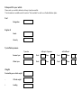
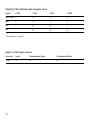
Data specific to your ve hicle
Please enter your vehicle’s data here to keep it ea sily accessible.
This information is available under the section "Technical da ta " as well as on the identification plate.
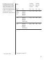
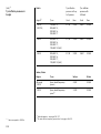
Fuel
Desi gnation
Engine oil
Grad e
Viscosity
Tyre inflation pressure
Tyre si ze
wi th full load
Front
R ear
Front
R ea r
Winter tyres
Front
R ear
Front
R ea r
Weights
Permissible gross vehicle weig ht
–
EC k erb weight
=
Loading
0
wi th up to 3 persons
Sum mer tyres
Your Om ega
Dev eloped to the la test findings of vehic le research, it offers technical sophistication and exceptiona l comfort.
Your vehicle represents an ideal synthesis of ad vanced technolog y, outsta nding safety, environm ental compatibility and economy in
opera tion.
It now lies with you to drive your vehicle safely and to see it performs perfectly.
This O wner's Manual provides you with all the necessary information to tha t end.
The O wner's Manual should a lways be kept in the v ehicle: ready to hand in the g lov e com partment.
Make use of the Owne r's Manual:
z
z
z
z
z
Its “I n Brief” section will give y ou a n initial ov erview.
Its index will help you find what y ou want.
It will familiarize you with the sophisticated technology.
It will increase your pleasure in y our vehicle.
It will help you to handle y our v ehicle ex pertly.
The O wner's Manual is designed to be clearly laid-out and easily understood.
This symb ol:
6 signifies: continue reading on next page.
3 The asterisk sig nifies equipment op tions not in all vehicles (model variants, engine options, models specific to one country, op tional
equipment, Genuine Vauxhall Parts and Accessories).
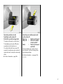
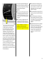
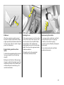
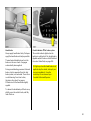
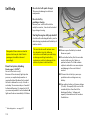
Text highlighted in yellow in p artic ular indica tes possible risk of accident and
injury. Disregard of these notes can lead to injuries which may b e fatal. Vehicle
passengers must b e informed accordingly.
Yellow arrows in the illustrations serve as points of reference or ind icate some action to be performed.
Black arrow s in the illustrations indicate a reaction or a second ac tion to be perform ed.
We w ish you m any hours of pleasurable driving
Your Va uxhall team
1
2
Contents
Comm itment to custom er
satisfaction:
Our ai m: to k eep you happy with your
vehicle. All Vauxhall Authorised Repairers
offer first class service at competitive
prices. Experienced, factory trained technicians w ork according to factory
instructions. Y our Authorised Repa irer can
supply you with GEN UINE VAU XHALL
APPRO VED PARTS , which hav e und ergone
stringent quality and precision chec ks, and
of course useful and attrac tiv e VAUXHALL
APPRO VED ACC ES SORI ES.
Our nam e i s your guara ntee!
For d eta ils of the
Va uxhall Authorised Rep airer Netw ork
please r ing this number 01582 - 427200
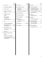
In b rief . ..... .... ..... .... .... ..... .... ..... .... ..... .... .... . 4
Instrum ents ... ..... .... .... ..... .... ..... .... ..... .... .. 26
K eys, doors, b onnet .. ..... .... ..... .... ..... .... .. 50
S eats, interior ..... .... .... ..... .... ..... .... ..... .... .. 63
S afety system s ... .... .... ..... .... ..... .... ..... .... .. 78
Lighting ..... .... ..... .... .... ..... .... ..... .... ..... .... 118
Windows, sun roof . .... ..... .... ..... .... ..... .... 122
Electronic air conditioning system . .... 126
Automatic transm ission .... ..... .... ..... .... 134
Driving hints . ..... .... .... ..... .... ..... .... ..... .... 140
S aving fuel ... ..... .... .... ..... .... ..... .... ..... .... 142
Env ironmental protection . ..... .... ..... .... 144
Fuel consum ption, fuel, refuelling .. .... 146
C atalytic converter, exhaust gases .... 148
Drive control system s .... .... ..... .... ..... .... 152
Brakes ... ..... .... ..... .... .... ..... .... ..... .... ..... .... 159
Wheels, tyres . ..... .... .... ..... .... ..... .... ..... .... 164
Roof racks,
Carava n and trailer towing ... ..... .... 168
S elf-help .... .... ..... .... .... ..... .... ..... .... ..... .... 174
If y ou ha ve a problem .... .... ..... .... ..... .... 196
Maintenance,
Inspection sy stem . ..... .... ..... .... ..... .... 198
Vehicle care .. ..... .... .... ..... .... ..... .... ..... .... 209
Technical data . .... .... ..... .... ..... .... ..... .... 213
Index . .... ..... .... ..... .... .... ..... .... ..... .... ..... .... 234
3
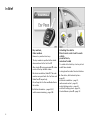
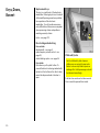
In Brief
Key num be rs,
Code numbers
Remove key number from keys.
The key number is specified in the vehic le
docum ents and in the C ar Pass 3.
Alloy wheels 3, towing equip ment 3 : m ake
a note of the key identifier cod es.
Elec tronic imm obilizer, Radio 3: The code
numb ers are specified in the Car Pass and
Radio Pass 3 respec tiv ely.
Do not keep the Car Pass and Ra dio Pass in
the vehicle.
6 Further information – pages 50, 51,
vehicle recomm issioning – page 208.
4
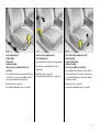
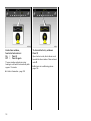
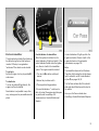
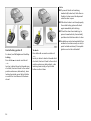
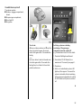
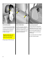
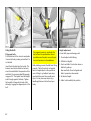
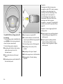
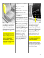
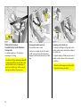
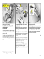
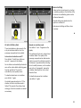
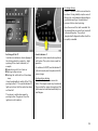
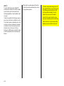
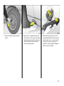
Unlocking the vehicle:
Direct remote control unit towards
vehicle ,
pre ss button q ,
raise door handle
To unlock with vehic le key: turn key in lock
and lift door handle.
Locking from the inside: Press lock buttons.
6 Door lock s, child restraint system –
pag e 50,
electronic immobilizer – p age 51,
radio remote control – p age 52,
central loc king sy stem – page 54,
anti-theft locking system – pag e 55,
Vauxhall alarm system 3 – page 59.
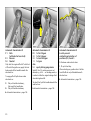
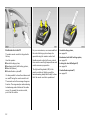
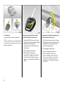
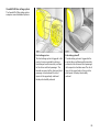
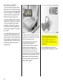
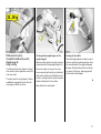
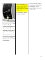
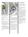
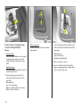
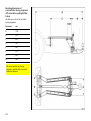
Seat adjus tme nt:
Pull handle,
slide s eat,
re lease handle,
allow seat to audibly latch into
pos ition
Never adjust the driver's sea t whilst driving.
It could m ov e in a n uncontrolled m anner
when the handle has been pulled.
6 S eat position – pa ge 63,
electrically a djustable seats – pa ge 66.
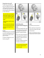
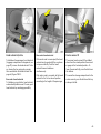
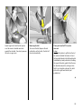
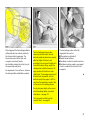
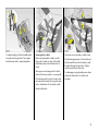
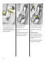
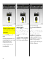
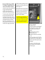
Se at backres t adjustment:
Turn handw hee l
Move seat backrest to suit seating position.
Do not lean on seat b ackrest whilst
adjusting it.
6 Seat position – page 63,
electrica lly adjusta ble sea ts – page 66.
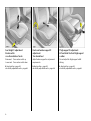
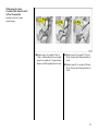
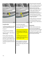
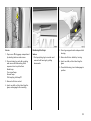
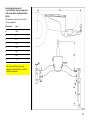
Seat inclination adjustm ent 3 :
Raise handle,
adjust inclination,
rele as e handle,
lock se at audibly in position
N ever adjust the inclina tion of the driver's
seat w hilst driving. The seat could move in
an uncontrolled manner when the handle
has been raised.
6 Sea t position – p age 63,
electrically adjustable seats – p age 66.
5
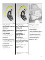
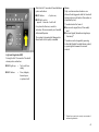
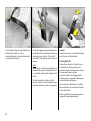
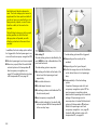
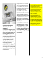
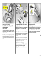
Seat he ight 3 adjus tme nt:
Rocker switch
on outboard side of se ats
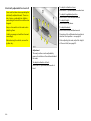
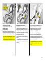
Front se at lumbar support 3
adjustme nt:
Turn handw hee l
Thigh support 3 adjustment:
Lift and slide the front thigh support
cus hion
Raise seat: Press roc ker switch up
Low er seat: Press roc ker switch down
Ad just lumbar support to suit p ersonal
requirements.
Do not adjust the thigh sup port whilst
driving.
6 S eat position – pa ge 63,
electrically a djustable seats – pa ge 66.
6 Seat position – page 63,
electrica lly adjusta ble sea ts – page 66.
6 Sea t position – p age 63,
electrically adjustable seats – p age 66.
6
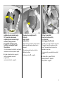
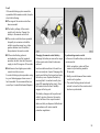
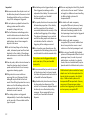
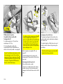
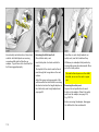
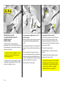
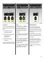
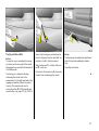
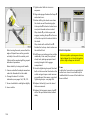
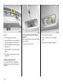
Adjusting head restraint angle :
Tilt forwards or backwards
Adjusting head restraint he ight:
Unlock by tilting forward
beyond the re sis tance point,
hold firmly and adjust height,
then rele as e
Steering wheel adjus tme nt 3:
Pull lever,
adjust height,
release lever
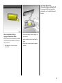
Fitting the seat belt:
Draw s eat belt smoothly
over shoulder
and engage in belt buckle
Ad just steering wheel only when vehicle is
stationary and steering column lock is
relea sed.
It is not necessary to unlock the rea r head
restraints in order to adjust the height.
The steering wheel can be set to five
different positions.
The belt m ust not be twisted at any point.
The lap belt must fit snugly across the
body . The seat back rest must not be
inclined too far back.
6 H ead restra int p osition – pag e 64,
further information, removal –
pages 64, 65,
rea r head restraints – p age 64.
6 Airbag systems 3 – pa ge 86.
To release b elt, p ress red button on belt
buckle.
6 S afety belts – pages 78 to 84,
airbag sy stems 3 – page 86,
seat position – pa ge 63.
7
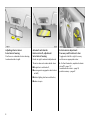
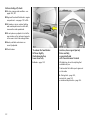
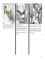
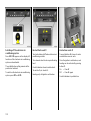
Adjusting interior m irror:
Swivel mirror hous ing
Pivot lev er on underside of mirror housing
to red uce daz zle a t nig ht.
Automatic anti-daz zle
interior mirror 3 , adjustm ent:
Swivel mirror housing
Dazzle at night is automa tic ally red uc ed.
The mirror does not reduc e da zzle when:
z the ig nition is sw itc hed off,
z rev erse gear is eng aged or selector lever
set to R,
z interior lighting has been switched on,
z a d oor is open.
8
Exterior m irror adjustment:
Four-way s witch in driver’s door
Toggle sw itc h to left or right: four-w ay
switch moves appropriate m irror.
6 Further inform ation, asp herical exterior
mirror 3 – page 117,
hea ted exterior m irrors – p age 18,
position m emory – pag e 67.
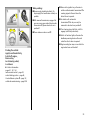
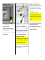
Folding exterior m irrors:
Starter switch:
Manually: Press lightly.
o = Ignition off
I = Steering released, ig nition off
II = Ignition on,
with diesel engine: preheating
III = Start (transmission in neutral)
Electrically 3: Press the button until the
mirrors reach their end positions. N ot
possible with manual adjustment.
Dise ngaging ste ering column lock:
To release the lock,
move the steering whe el slightly
and turn the key to position I
6 R emoving k ey and enga ging steering
column lock – page 23.
6 Starting – page 21,
electronic im mobilizer – page 51.
9
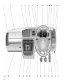
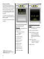
10
1
Page
Side air v ents ... ..... .... ..... .... .... ..... .... 128
11
2
Front pa ssenger airbag 3 .... ..... .... . 86
3
Centre air v ents .... .... ..... .... .... ..... ... 128
4
Electronic air conditioning
system . .... ..... .... ..... .... ..... .... .... ..... ... 126
5
Display for time, date,
radio 3 ,
check control 3,
trip computer 3,
infotainment sy stem 3 . .... .... ..... .... . 32
6
Horn .... .... ..... .... ..... .... ..... .... .... ..... .... .. 16
7
Turn signals, hea dlamp flash,
dipped and main beam ... .... .... 14, 15
Cruise control 3 .... .... ..... .... .... ..... .... 157
8
Radio/infotainment system
rem ote control.. ..... .... ..... .... .... ..... .... . 48
9
Instruments .. .... ..... .... ..... .... .... ..... .... . 26
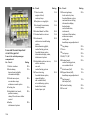
Pa ge
Light switch ..... .... ..... .... .... ..... .. 14, 118
Page
19 Fuse box ..... .... .... ..... .... ..... .... ..... .... 185
12
Instrument illumination ... ..... .... ....
Fog tail lamp ... .... ..... .... .... ..... .... ....
Fog lam ps 3 .... .... ..... .... .... ..... .... ....
Head la mp range adjustm ent 3 ..
13
Bonnet release lev er . .... .... ..... .... ..... . 62
20 S eat heating (right) 3 ..... .... ..... .... 132
Vauxhall alarm system 3 .... ..... .... .. 59
Traction Control sy stem 3 .. ..... .... 153
or Electronic Stability Program 3 154
Boot lid/tailgate 3 .. .... ..... .... ..... .... .. 57
14
Stowage compartment
15
Ac celera tor pedal .... .... .... ..... 140, 141
16
Starter switch
with steering column lock
(not visible) . ..... .... ..... .... .... ..... .... ..... ... 9
120
119
119
118
17
Brake peda l ..... .... ..... .... .... . 159 to 163
18
Clutch ped al .... .... ..... .... .... ..... .... .... 141
21 Ashtray
with cigarette lighter .. ..... .... ..... 75, 76
22 Rad io 3
or infotainm ent system 3 ... ..... .... .. 47
23 S eat heating (left) 3 ... ..... .... ..... .... 132
Haz ard warning lights .... .... ..... .... .. 15
Rear window blind 3 .. ..... .... ..... .... 125
24 Glove compartment
with telematics unit 3 ..... .... ..... .... .. 47
10 Wind screen wipers and wash
system,
head lamp wash system 3 and
rear window wash system 3 . ..... 16, 17
Trip computer 3 ... .... ..... .... .... ..... .... . 42
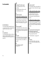
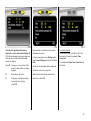
1111
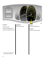
Control indicators
A
Engine elect ronics,
tra nsm issi on electr oni cs 3,
im mobili zer 3,
fault
see pages 28, 51, 150.
O
Turn sig na l lam ps,
see p ages 15, 26.
!
Glow plug s 3,
see p age 26.
W
Coolant t em perature 3,
see p age 26.
g
Tra iler turn signal 3,
see p age 26.
=
X
Sea t belt 3,
see p age 26.
v
u
Anti-lock brak e system 3,
see p age 162.
R
Z
Brak e system,
clut ch system,
see page 28, 204.
Exhaust em issi on 3,
see p ages 26, 150.
p
1
Automat ic transmi ssion 3 ,
sp orty d riving program me,
see p age 136.
Alt ernat or,
see page 29.
>
Fog lam ps 3,
see pages 29, 119.
P
Main beam ,
see p ages 14, 26.
r
Fog tai l lam p,
see pages 29, 119.
I
Oil p ressure,
see p age 27.
Y
Fuel lev el ,
see pages 29, 174.
?
Autom atic head lamp range
ad just ment 3,
fault ,
see page 119.
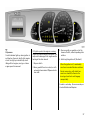
12
v
Airb ag systems 3 ,
belt tensioners,
see pages 81, 89.
Tract ion Control System 3,
see page 152.
Elec tronic St abili ty Progr am 3 ,
see page 154.
F
Brake pa d wear i nd icator 3,
see pages 29, 159.
y
Seat occup ancy recog nition 3,
see page 90.
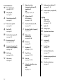
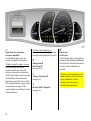
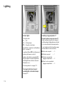
Lighting
Li ght switc h,
st alk positions,
see pages 14, 118,
7
8
9
Li ghts off,
0
Courtesy la mp,
see page 119.
>
Fog lamp s 3 ,
see page 119.
r
Fog tail l amp,
see page 119.
k
Instrument il luminati on,
see page 119.
?
Hea dlam p range ad justment,
see page 118.
¨
Hazard w arning la mps,
see page 15.
Pa rking lamp s,
Dipped and main b ea m
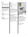
Heating, ventilation
electronic air conditioning system ,
seat heating
V
Demi st ing and d e-i cing,
Air d istribution to wind screen
and front d oor windows.
x
Air flow,
see p age 131.
t
Air circ ul ation system,
see p age 129.
Air distri bution,
see p age 131,
s
M
to wind screen
to head area ab ov e
adjustable air vents
front and rear 3
K
to foot area
Ü
Hea ted rear wind ow,
see p age 130.
Sun roof
Sun roof 3
closing – see page 124.
p
Central l ocking system 3,
loc king – see pag e 52.
ü
Sun roof 3
opening – see page 124.
q
Central l ocking system 3,
unlocking – see page 52.
q
Sun roof 3
raising – see page 124.
r
Boot lid/ta ilgat e 3 ,
unlocking – see page 56.
x
Lug gage comp artm ent 3,
unlocking – see page 56.
)
Ciga ret te lighter,
see page 75.
j
Horn,
see page 16.
Ä
Va uxhall alarm system,
see page 59.
/
Bonnet,
see page 62.
T
Wi nter program ,
automa tic tr ansm issi on 3,
see page 136.
+
Fir st Aid k it 3,
see pages 178.
¨
Wa rning tri angle 3,
see pages 178.
N
Rear wind ow blind ,
see page 125.
Windscre en wipers
St alk p osi tions,
see page 16,
§
$
O ff,
%
&
Sl ow ,
Timed interval w ipe or
autom atic wipi ng 3,
Fast.
Date, time, radio
Inform ation d isp lay 3,
see page 32,
AUTO Automat ic mode,
see p age 127.
Ö
O n button for date
and time,
ECO
;
Setting buttons for date and time.
O FF
ß
Operati on without c ooling,
see p age 130.
Switc hing off electronic a ir
conditioning ,
see p age 132.
Hea ted seat s 3,
see p age 132.
Misce llaneous
l
St eering w heel w ith remote
control 3,
see page 48.
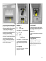
13
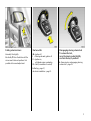
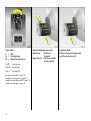
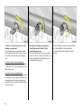
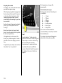
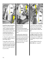
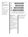
Light switch:
7 =
Off
8 =
Parking lamps
9 =
Dipped or m ain beam
Pull 0
= Courtesy lamp
Push r = Fog tail la mp
Push > = Fog lamps 3
6 Further informa tion – page 118,
head la mp warning device – p age 23,
head la mp range adjustm ent 3 – page 118,
day tim e running lights – page 118.
14
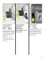
Main and dipped be am switch:
Main be am
= Push le ver
forw ards
Dippe d beam = Pull lever towards
steering wheel
Headlamp flash:
P ull lever towards ste ering wheel
past the res istance point
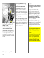
Operating turn signal lam ps :
Leve r in res t position
Right turn =
Upwards
Left turn
=
Downwards
When the steering wheel is turned back, the
lev er automatically returns to its original
position. This will not hap pen when making
a m inor steering manoeuvre such as
changing lane.
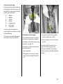
Operating parking lamps:
Starter switch to o,
Light s witch to 0,
Re move ignition key,
Move turn signal lever up or down
from rest position
Hazard w arning lights:
On
= Press ¨
Off = Press ¨ again
To aid loc ation of the pushbutton, the red
surfac e is illuminated w hen the ignition
switched on. When the button is pressed,
its control indicator flashes in time with the
hazard warning lamps.
When lane chang ing, move lev er to
resista nce point. When released , the lever
will spring back.
15
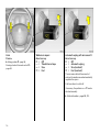
Horn:
Press j
6 Airbag sy stems 3 – page 86,
Steering wheel with remote c ontrol 3 –
page 48.
Windscre en wipers:
Move lever up
§ =
Off
$ =
Tim ed interval wipe
% =
Slow
& =
Fast
Automatic wiping with rain s ens or 3:
Move lever up
§ =
Off
$ =
Automatic wiping
% =
Slow (constant)
& =
Fast (constant)
The ra in sensor detects the a mount of
water on the windsc reen and automatically
regula tes the wipers.
Push lever down to switch off.
If necessary , the positions % or & can be
selected manually.
6 Further information – pages 204, 210.
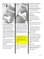
16
Operating windscre en and
headlamp wash systems 3:
Pull stalk tow ards steering wheel
The w ip ers will swipe for a few strokes.
The headlamp wash system 3 c an be
opera ted when the lights are on.
O n vehicles fitted with rain sensors 3,
opera te the wind screen wash system at
reg ular intervals, to keep the sensor a rea
clean.
6 Further inform ation – page 206.
Operating re ar window wipe r and
wash systems 3:
Wiper on
= Push le ver forward
Wiper off
= Pull lever towards
steering wheel
Wash
= Push le ver forward
and hold
The rea r window wiper wipes in timed
interval mode. C ontinuous wip ing takes
place during washing.
6 Further information – see pa ges 206,
211, 212.
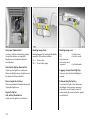
17
Heate d re ar window,
heated exterior mirrors :
On
= Pre ss Ü
Off = Pre ss Ü again
The rear window and exterior mirror
heating is switched off automatically after
approx. 15 m inutes.
6 Further inform ation – page 130.
18
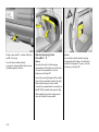
To clear mis ted or icy windows:
Pre ss V
Open front air vents, direct side air v ents
tow ards the door w indows. Close centre a ir
vents 3.
6 Electronic air conditioning system –
page 126.
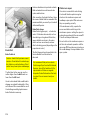
Manual transmission:
o
= Neutral
1 to 5 = 1st to 5th ge ar
When shifting up from 4th to 5th gear:
push the lev er towards the right at the
beginning of the shift opera tion.
Manual trans miss ion:
R = Re ve rse gear
Only engag e reverse g ear when the vehicle
is stationary . This is done by p ulling up the
ring below the shift knob.
When shifting from 5th to 4th g ear:
do not exert a ny force towards the left.
19
Autom atic transmission 3:
P = Park
(with s ele ctor le ver lock)
R = Reve rse
N = Neutral
O nly start the engine in P or N. To shift out
of P switch the ignition on, apply the foot
brake and p ull the handle b eneath the
selector lever.
To enga ge P or R pull release under
selector lever.
P:
R:
O nly with vehicle stationary ,
first a pply the hand brake
O nly with vehicle stationary
6 Automatic transmission – p age 134.
20
Automatic trans miss ion 3:
D = 1s t to 4th ge ar
3 = 1s t to 3rd gear
2 = 1s t and 2nd gear
1 = 1s t ge ar
also
S = sporty driving programme
Select 3, 2 or 1 if certain gears are not
desired, e.g. 4-3-4 . . . on winding road s, or
in order to utilize the engine brak ing effect
when driving downhill.
To select 3 or 1 p ull the handle beneath the
selector lever.
6 Autom atic transm ission – page 134.
Automatic transmission 3:
Lock to prevent
unintentional selection of
positions P, R, 3 and 1 :
Pull release under selector lever:
1, P: up to final stop.
When selec ting any position from 1 to N or
from R to D do not pull ha nd le beneath
selector lever.
6 Automatic tra nsmission – page 134.
Starting, petrol engine:
Manual transmission: in neutral with
clutch depres sed,
Apply foot brake,
Autom atic transmission: in P or N,
Do not accelerate ,
Turn key to position III
The initially increased engine speed
automatically fa lls as the engine
tem perature rises.
Before repeating the starting proced ure,
turn the k ey ba ck to o in the starter switch,
rem ov e it a nd then reinsert it. Then repea t
the starting proced ure.
6 Electronic immobilizer – page 51,
further information –
pages 140, 142, 144, 174.
Starting, diesel engine :
Manual trans miss ion: in ne utral with
clutch depresse d,
Apply foot brake ,
Automatic trans miss ion: in P or N,
Do not accelerate,
Turn key to position II,
When control indicator !
goes out 1),
turn key to pos ition III
Exhaust gases are poisonous
Before repea ting the starting proc edure,
turn the key back to o in the sta rter switch,
remove it and then reinsert it. Then repeat
the starting proc edure.
6 Exhaust gases – page 151.
Exhaust g ases contain ca rbon monox ide,
which is ex tremely poisonous but is
odourless and colourless.
Therefore never inhale exhaust gases, and
nev er run the engine in an enclosed space.
Y ou should also avoid driving w ith the
tailgate open, as ex haust gases could
enter the p assenger compartment.
6 Electronic immobilizer – page 51,
further information –
pages 140, 142, 144, 174.
1)
Prehea ting system switches o n only if ou tsid e
temp era ture is lo w.
21
Before starting off, check:
z For tyre pressure and c ondition – see
pages 165, 227.
z Engine oil level and fluid levels in engine
com partment – see pages 199 to 206.
z All windows, mirrors, exterior lighting
and num ber p la tes are free from dirt,
snow and ice and op erational.
z Do not p la ce a ny objects in front of the
rear window, on the instrum ent panel or
in the area in which the airbag s inflate.
z Seats, seat belts and mirrors are
correctly ad justed.
z Check brakes.
To re lease the hand brake:
Lift lever slightly,
Pus h release button,
Lowe r lever fully
And now, have a good journey!
Drive carefully,
economically and
with the environme nt in m ind
6 Brakes – pag e 159.
While driving, do not do anything that
could distract you.
Take heed of the traffic reports given out
on the ra dio.
6 Driv ing hints – p age 140,
saving fuel – page 142,
env ironmental protection – page 144.
22
When parking:
z Always ap ply hand brak e firmly . O n
slop es apply the hand brake as firmly as
possible.
z With manual transmission, engage first
gear or reverse gear and with automatic
transm ission 3, pla ce selector lev er in
position P.
z C lose windows a nd sun roof 3.
z Remov e the ignition key, otherwise in
vehicles with automatic transmission 3 a
warning signal w ill sound when the
driver's door is opened.
z In vehicles with autom atic
tra nsmission 3 the key ca n only be
removed in selector lever position P.
z Turn steering wheel until lock is felt to
engage (anti-theft protection).
z Switch off ex terior lights, otherwise the
headlam p warning device will sound
when the driver's door is opened .
z Engine cooling fan m ay run on after the
engine has been switched off.
Parking the vehicle :
Apply hand brake firmly,
Switch off engine ,
Remove key,
Lock steering w hee l,
Lock doors
6 Further informa tion –
pages 51, 141, 161,
radio remote control – p age 52,
central lock ing sy stem – page 54,
Vauxhall alarm system 3 – page 59,
vehic le decommissioning – page 208.
23
Ge nuine Vauxhall P arts and
Accessories
We rec om mend that you use "Genuine
Vauxhall Parts and Accessories" a nd
conv ersion p arts released ex pressly for
your vehicle type. These parts ha ve
undergone spec ia l tests to establish their
reliability, safety a nd specific suitability for
Vauxhall v ehicles. Despite continuous
market monitoring, we ca nnot assess or
guarantee these attributes for other
prod uc ts, even if they hav e b een granted
approval by the releva nt authorities or in
some other form.
Service work,
Mainte nance
We recomm end tha t you entrust all w ork to
your Vauxhall Authorised R epairer, who
can provide y ou w ith reliable service and
correctly perform all work according to
factory instructions.
6 Vauxhall S ervice – page 196.
24
"Genuine Vauxhall Parts and Accessories"
and approved conversion parts are
available from your Vauxhall Authorised
Repairer, who can p rovid e expert advice,
such as adv ice on permissible technical
modifications, and install products
correctly.
For your safety
Carry out the check s recommend ed in
the individual sec tions of this O wner’s
Manual regularly.
Ensure that your vehicle is serviced as
specified in the Service Book let. We
recommend that you consult your
Vauxhall Authorised Repairer.
Have faults remedied w ithout delay!
Consult a work shop. We recom mend
your Vaux ha ll Authorised Repairer. If
necessary, interrupt your journey .
6 Maintenance – pages 198 to 207
That was a brief overview.
P lease read on!
6
Your vehicle has still more
instruments
and controls ,
possibly also optional
equipment.
6
You will also find further
important information on
operation,
safety and
maintenance
and a complete
index.
6
25
Instruments
!
Z
Preheating 3 for diesel eng ines
Control indica tor lights up during
prehea ting.
Exhaust emi ssion 3
C ontrol indicator lights up when ignition is
switched on. Goes out shortly after engine
starts.
Preheating system switches on only if
outside temperature is low.
W
Coolant tem perature
If it lights up when the engine is running:
Stop the v ehicle a nd switch off the eng ine.
Coolant tempera ture is too high: Switch off
the engine. Danger to engine. Coolant
temperature gauge; see pag e 31. C heck
coolant level immediately ; see page 203.
Control indicators
The c ontrol indicators described here are
not present in all vehicles. The description
applies to all instrument v ersions.
O
Turn signal l amps
The control indicator flashes when the turn
signa l is activated . Rapid fla shes: A turn
signa l bulb has failed. Changing bulb s, see
page 188.
g
Tr ailer turn signal 3
Control indica tor flashes in time with turn
signal lamps w hen towing. Does not flash if
a turn signal la mp on the towing v ehicle or
tra iler fails.
X
Seat belt 3
Control indica tor lights up (accomp anied
by an a coustic warning) when ignition is
switched on: Fasten your seat belt, see
page 82.
u
Anti-lock brak e system 3
see p age 162.
26
If it lights up when the eng ine is running:
Fault in emission c ontrol system. The
permitted emission limits may be
exceeded. C onsult a workshop. We
recommend your Vaux hall Authorised
Repairer.
If it flashes when the engine is running:
For fault that can lead to d estruction of the
cataly tic converter, see page 150. C onsult
a work shop imm ediately. We recom mend
that you consult y our Vauxhall Authorised
Repairer.
1
Autom atic transmission elec tronical ly
contr olled driv e p rogram mes 3
C ontrol indicator lights up when sporty
driving p rogram me operative.
Further information – see page 136.
P
Ma in beam
C ontrol indicator lights up when ma in
beam is on and w hen headlam p flash is
operated.
I
O il pressure
Control indicator lights up when ignition is
switched on. Goes out shortly after engine
starts. Can light up intermittently when
idling with hot engine; must go out when
engine sp eed is increased.
If it lights up when the engine is running:
Engine lub ric ation may be interrupted . This
may result in dam age to the engine and/or
lock ing of the drive wheels:
1. Depress clutch.
2. Move gearshift lev er to neutral, or with
automatic transmission 3 place selector
lever in N .
3. Steer as quickly as possible out of the
stream of traffic, without imped ing other
vehicles.
4. Switching the ignition off (Position I ).
When the ignition is off, c onsiderab ly
more force is needed to brak e and steer.
Do not remove key until vehicle has
come to a stand still, otherwise the
steering column lock c ould engage
unexpectedly .
C ontact a workshop. We recommend your
Vauxhall Authorised Repairer.
27
A
Eng ine electr oni cs, transmission
electronics, im mobil izer
Control indicator lights up for a few
seconds when ignition is switched on.
If it lights up when the engine is running:
Fault in the engine electronics or
transm ission elec tronics sy stem. The
electronic sy stem switches to limp-home
mode. Fuel consumption may increase and
the d riv eability of the vehicle m ay be
impaired; see pag e 150. If there is a fault in
the transmission elec tronics sy stem, switch
to manual gears; see page 138. We
recom mend tha t you consult your Vauxhall
Authorised Repairer.
28
If it flashes when the ignition is on:
Fault in the electronic im mobilizer system ;
the engine cannot be started. S ee p age 51.
v
Airbag systems 3,
Belt tensioners 3
see p ages 81, 89.
=
Tr action C ontrol system 3
see p age 152.
v
Electronic Stab ility Program 3
see p age 154.
R
Brak e system,
cl ut ch system
C ontrol indicator lights up when ignition is
switched on if hand brake is a pplied and/or
the fluid lev el for brake/clutch hy draulics is
too low. For further informa tion, see
pag e 204.
If it lig hts up when the hand brak e is not
applied : stop the vehicle; interrup t your
journey immediately . C onsult a
workshop. We rec om mend your
Vauxhall Authorised Repairer.
p
Y
Alternat or
Control indicator lights up when ignition is
switched on. Goes out shortly after engine
starts.
Fuel level
Illum inated: Fuel supply low , fuel ga uge in
reserve area .
If it lights up when the engine is running:
Stop the vehicle and switch off the engine.
The b attery is not being charged. Engine
cooling may be interrupted. Conta ct a
workshop. We recommend your Vauxhall
Authorised Repairer.
>
Fog lam ps 3
Control ind ic ator lights up when fog lamps
are sw itched on.
r
Fog tail lamp s
Control indicator lights up when fog tail
lamp is switched on.
Flashing: Fuel supp ly used up, fill tank
immed iately.
Nev er let the tank run dry !
Diesel engines: if the tank becomes em pty,
a complicated procedure is necessary to
bleed the fuel system . We recommend that
you consult your Vauxhall Authorised
Repairer; see page 174.
?
Fault in autom atic head lamp range
adjustm ent syst em 3
Control indica tor lights up when the
ignition is switched on. Goes out after a few
second s. I f it lights up while driving, a fault
ha s occurred . C onsult a workshop
immed iately. We recommend your
Vauxhall Authorised Repairer; see pa ge
119.
F
Brak e pad w ear indic ator 3
If it lights while the engine is running : Front
disc brak e pa ds are worn down to the
minimum thickness. Consult a w ork shop to
have the brake pads replac ed. We
recommend your Vaux hall Authorised
Repairer; see page159.
y
Seat occupancy recogniti on 3,
see pages 90, 91.
29
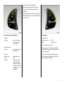
Tachometer 1)
Spee dome ter 1)
Odometer
Indicates engine speed.
Indicates the vehicle speed .
Records the miles/kilometres driven.
Warning zone: M aximum p ermissible
engine sp eed ex ceeded ; danger to engine.
1)
The instrum ents in yo ur vehicle m ay d iffer
from the instrum ents illustra ted here.
30
Trip odometer
To return to zero, depress reset k nob.
For physical reasons, the engine
temperature gauge show s the coolant
temperature only if the coolant level is
adeq uate.
During operation the system is pressurised.
The temp erature ma y therefore rise briefly
to ov er 100 °C.
Coolant te mperature display
Fuel gauge
Pointer in
low zone
Pointer in red
warning zone or
Y lit
Pointer between
the z ones
Pointer in
red warning
zone
or W is lit
=
Engine operating
temperature not
yet reached
=
Normal operating
temperature
=
Temperature too
high:
Stop vehicle and
switch off eng ine.
Danger to engine.
Check coolant level
immediately – see
page 203
=
Refuel –
see pag e 147.
N ever let the tank run dry!
Diesel engines: The fuel system is d ifficult
to bleed if the tank has b een allowed to run
dry ; see page 174.
O n account of the fuel remaining in the
tank, the am ount filled may be less than
the specified ta nk capacity .
31
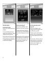
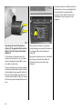
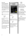
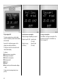
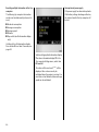
Inform ation display
Tripl e inform ation d isp lay
Display of time, outside tempera ture and
radio/d ate.
The tim e and outside temperature are
displayed when the ignition is on. The date
is disp layed when the radio 3 is off.
When the ignition is off, the time, date and
outside tem perature can be disp la yed for
15 second s b y briefly pressing one of the
two buttons a bove the display.
32
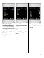
Multi-inform ation d isp lay 3
Display of date, radio 3 /date, outsid e
temperature, c heck control, trip comp uter.
The display operates when the ignition is
switched on. Time is continually d isplay ed
while the date is displayed when the radio
is off.
When the ignition is off, the time, date and
outside temperature can b e display ed for
15 seconds by briefly p ressing one of the
two buttons above the display or the
button on the wiper lever.
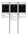
Mult i-informa tion displa y for ra dio
telephone 3
Display of time, rad io/date, outside
temperature, telephone information, check
control 3 and trip computer 3 .
The display opera tes when the ignition is
switched on. Tim e is continua lly displayed
while the date is disp la yed when the ra dio
is off.
When the ignition is off, the tim e, date and
outside temperature can be displayed for
15 seconds by briefly pressing one of the
two buttons above the display or the
button on the wiper lev er 3 .
I nt err up tion of pow er supp ly
After a power supply interrup tion or low
battery voltage the electronic rad io
disabler 3 and d ate/tim e m ust be reset.
S ee rad io operating instructions for how to
reset electronic disab ler. S etting date and
time – see pa ge 38.
Upon receipt of a tim e signal from an RDS
transmitter 1) , date and time are set
automatically 3 – see page 38.
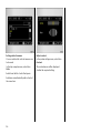
Grap hi cal inform ation d isp lay 3,
Col our informati on display 3
Display of date, tim e, outside temperature,
and information from check control 3, trip
computer 3 and infotainment system.
The information displayed depends on the
vehicle equipm ent and the setting s of the
trip computer 3 and the infotainment
sy stem.
Fault d isplay
--.- ° C, F or S afe in the display ind icates a
fault. Ha ve the cause remed ied. We
recommend that y ou consult y our Vauxhall
Authorised Repa irer.
The graphical information display presents
the information in m onochrome. The colour
inform ation d isplay presents the
inform ation in colour.
1)
RDS = R a dio Da ta System.
33
O peration using the multifunction button:
Individ ual menu item s are highlighted by
turning the button and selected b y
pressing it. Press the BC button on the
infota inm ent system to open the trip
computer.
Operating the multi-information
display 3, the graphical information
display 3 or the colour information
display 3
Trip computer functions are operated
using the disp la y menu and the buttons on
the wiper lev er 3 or the infotainment
sy stem 3.
The functions are opera ted using the
buttons on the wiper lever or, on vehicles
with an infotainm ent system 3, by using
the m ultifunction b utton.
Operation using the wiper lever: Individual
functions a re selected using button S.
Certain functions can be reset using
button R.
If chec k control issues a warning message,
the display is blocked from other func tions.
Acknowled ge the message with b utton S or
R on the wiper lever 3 or by pressing the
multifunction button 3 . If there are several
fault warnings, ack nowledge them one a t a
time.
34
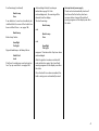
Making system settings for
the graphical information display 3
or the colour information dis play 3
Lang uage selecti on
You can select the d isplay language for
some func tions.
The figures show execution with the colour
inform ation d isplay .
In the trip com puter menu, select item
Instructions.
In the trip computer m enu Setti ng s select
System Setting s.
The list of available languages will b e
display ed.
S elec t the required language from the list.
S elec tions are indic ated b y a 6 in front of
the menu item.
The system settings m enu will be
displayed.
35
Setti ng units of measure
You ca n select w hich units of measure a re
to be used.
Adjust contra st
In the system settings m enu, select item
Contrast.
In the trip computer m enu, select item
Units.
The contrast m enu will be displayed.
Select from the list of units that opens.
Selections are indicated by a 6 in front of
the m enu item .
36
Confirm the required setting.
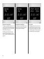
Outs ide tempe rature
A fall in temperature is indica ted
immediately and a rise in temp erature
after a time delay .
O n v ehicles with trip le inform ation display,
the sym bol T is shown in the disp lay from
3 °C as a warning for icy road surfaces.
On vehicles with graphical information
display 3 or colour information display 3, a
message is shown in the display to w arn for
icy road surfaces.
C aution: The road surface ma y already
be icy even thoug h the display ind ic ates
a few degrees above 0 °C.
O n vehicles w ith m ulti-information
display 3, outside temperature is
automatically shown in the d isplay
from 3 °C .
37
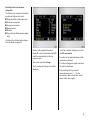
Setting date and time
In the infotainment system 3, tim e a nd
date are set autom atic ally upon receipt of
GPS satellite signals1 ). If the tim e displayed
does not correspond to the loc al time, it
can be set m anually in 30-minute steps or
be corrected automatically 3 via a n RDS
time sig nal2 ).
For the radio, tim e and date can be set
manually or corrected a utoma tica lly v ia an
RDS tim e signal 3 .
The a utomatic setting is indicated by Ö in
the d isplay .
Vehicles with trip le informa tion display or
multi-i nfor mati on d isplay 3
Manua l setting
Switch off radio. Press Ö and ; a bove the
display as follow s:
Press Ö for approx. 2 seconds:
Day flashes
Press ; : Set day
Press Ö : Month flashes
Press ; : Set month
Press Ö : Y ear flashes
Press ; : Set year
Press Ö : Hours fla sh
Press ; : Set hours
Press Ö : Minutes flash
Press ; : Set minutes
1)
2)
GPS = G lob al P ositioning System,
Sa tellite system for w orld -w ide p ositioning .
RDS = Ra dio D a ta System.
38
Press Ö : C lock is started.
Deactivating and a ctiv ating automatic
setting 3
Press Ö for ap prox . 2 sec., clock display is
now in setting mode,
Press Ö twice (until year flashes).
Press Ö and hold down for approx.
3 seconds until } fla shes in
disp lay and text " RDS TIME"
appears (y ears flash during this
time),
Press ; Display indicates:
RDS TIME 0 = Deactivated
RDS TIME 1 = Activated
Press Ö three tim es.
Vehi cles w ith gra phical informati on
displ ay 3 or colour inform ation di sp lay 3
With the infota inm ent system on, da te and
time can be set with buttons Ö and ;
above the display :
Press Ö
Date and tim e c an also be set using the
infotainment system :
In the trip com puter menu Settings select
item S ystem S ett ings and then item Tim e/
Da te.
for ap prox . 3 seconds until the
menu for date and time setting
appea rs.
The menu for time/d ate w ill be d isplay ed.
Ö
Move a bout the menu.
Make the desired settings and confirm.
;
Change or confirm the setting .
To activate the settings,
select O K.
Select menu item O K.
C orrecting time 3
To correc t the time, use RDS in the Time/
Date menu to select item Auto. Ti me
C orrec tion.
The field behind Auto. Time Correcti on will
be ticked.
Select the menu item s required:
39
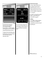
Automat ic
Gea rbox 3
Check control 3
The c heck control monitors fluid levels,
front disc brake pad thickness, the
func tioning of the a utoma tic transmission
3 a nd the automatic headlamp ra ng e
adjustm ent 3 as well as important ex terior
lamp bulbs, including the wiring and fuses.
In the case of the bulb monitoring system ,
a fault is not indicated unless the relev ant
circuit is switched on.
Fault. Transm ission no longer shifts
automatically. Change gears m anually ;
see page 138. Have the ca use of the fault
remedied. We recommend that you consult
y our Vauxhall Authorised Repairer.
Hea dlam p Range
Ajustment-Headl ight
O nce the ignition has been switched on, all
check control functions a re automatically
verified.
If all the monitored functions are OK , the
warning
Brake Lamp
Check
goes out after the brake pedal has been
depressed once.
Fault warnings app ear in the disp lay. O n
vehic les with multi-information display,
CH ECK also appears (not on vehicles with
radio telephone). I f there a re sev eral fault
warnings, they are displayed one after the
other.
Some of the fa ult w arnings appear on the
display in a n abbrev iated form.
Figure 7570 V shows a fault warning in a
multi-information display.
40
Fault warnings:
Engine Oil
Lev el
Engine oil level too low . Check oil level
immed iately and top up oil – see page 200.
Cool ant
Lev el
Coolant level in expansion tank is too low.
Top up coolant; see page 203. H ave the
cause of the fault remedied. We
recommend that you consult your Vauxhall
Authorised Repairer.
Fault. The range of the Xenon headlamps
is no longer regulated autom atic ally. Have
the cause of the fault remedied
imm ediately. We recomm end that y ou
consult y our Vauxhall Authorised Repairer.
Brake Pad
Front disc brake p ads are worn down to the
minimum thickness. Consult a w ork shop to
have the brake pads replac ed. We
recommend your Vaux hall Authorised
Repairer.
Fault warnings (continued)
Brake Lamp
Fuse
Fuse defective. A new fuse should only be
installed after the cause of the trouble has
been rectified. Fuses – see page 186.
Brake lam p
Ac know ledge the fault wa rning as
indica ted on pa ge 34. After
acknowledgement, the wa rning will be
cleared from the display .
The fault warning s
Brak e lamp
and
Brak e Lam p
Fuse
Brake lamp failure.
Hea dlight
Ta il Light
Dipped head lamp or tail lam p failure.
Wa sh Fluid
Level
Fluid level in windscreen wash system too
low. Top up wash fluid – see page 206.
I nt err up tion of pow er supp ly
C heck c ontrol automatically checks all
functions after the battery has been
reconnected or c ha rg ed. Stored fault
warnings appear on the display one after
the other.
and
Headl ight
Tail Lig ht
reappear 15 m inutes after they have been
acknowledged.
After the ignition has been switched off
and switc hed on aga in, the stored fault
warnings app ear on the disp la y one after
the other.
Once the faults ha ve been remedied , the
fa ult w arnings are automatically erased.
41
Trip computer 3
The trip computer show s v ehicle data
which it continually records and evaluates
electronic ally .
Some of the functions a ppear on the
display in a n abbrev iated form.
The figures show the v ersion w ith m ultiinform ation d isplay .
Functions:
z Instantaneous consumption
z Av erage consump tion
z Ab solute consumption
z Av erage speed
z Distance
z Rang e
z Stop watch (multi-informa tion display
only).
Check control warnings a lways have
priority.
42
Instantaneous consumption
Display changes depending on speed:
Display in gal/h (l/h)
below 8 m ph
(13 km/h)
Display in mpg
(l/100 km )
above 8 mph
(13 km/h)
Av era ge consum ption
C alcula tion of av erage consump tion. The
measurement c an be re-started at any
time; see page 34.
Absolute consumpt ion
Shows the a mount of fuel consumed . The
measurement ca n be re-started at a ny
time; see page 34.
Average speed
Calculation of avera ge c onsumption. The
measurement can be re-started at any
tim e; see page 34.
Distanc e
S hows the numb er of miles (k m) travelled.
The measurement can be re-started at any
time; see page 34.
Stoppages in the journey with the ignition
off are not includ ed in the calculations.
43
Range ov er 30 mil es (50 k m)
The range is calculated from the current
contents of the fuel tank and the a verage
consump tion over the last 12 to 20 m iles
(20 to 30 km) of the journey.
After filling up the vehicle, the ra nge
adjusts itself automatically after a short
time. It can also be adjusted manually; see
page 34.
44
Range below 30 miles (50 km )
If the fuel in the tank will a llow less than
30 miles (50 km) of trav el, the warning
"Range" appears in the display.
St op wa tch 3
C alcula ting tra vel tim e: The stop watch is
switched off when the ignition is switched
off and continues running once the engine
is switched on aga in. The stop watch can
be re-started at any tim e; see p age 34.
Reset ting current t rip com puter
informa tion
The following trip computer information
can be reset (values set to z ero):
z
z
z
z
z
z
Rang e (only with v ehicle stationary)
Ab solute consumption
Av erage consump tion
Av erage speed
Distance
Stop watch (multi-informa tion display
only).
Vehicles with multi-informa tion display :
Press button R ; see page 34.
Vehicles with graphical inform ation
display 3 or colour inform ation display 3:
Select the desired item from the trip
computer menu.
In the Trip computer-Setting s m enu, select
item BC r eset present .
Then select menu item Setti ng s.
The value for Range can only be reset when
the vehicle is stationary.
The Trip computer-S ettings menu w ill be
display ed.
The value for the selected function will be
reset and recalcula ted.
After resetting , the trip computer
inform ation may show "- - -" for the
selected item. After a short tim e, actual
va lues will be shown again.
45
Reset ting mul tiple inform ation in the tri p
com puter
The following trip computer information
can be reset sim ultaneously (va lues set to
zero):
z
z
z
z
z
I nt err up tion of pow er supp ly
If the power supp ly has been interrupted or
if the battery voltage ha s dropped too low,
the values stored in the trip computer w ill
be lost.
Ab solute consumption
Av erage consump tion
Av erage speed
Distance
Stop watch (multi-informa tion display
only).
Vehicles with multi-informa tion display :
Press button R for at least 2 seconds; see
page 34.
Vehicles with grap hical informa tion display
3 or colour information display 3: In the
Trip computer-Setting s m enu, select item
BC reset all.
The values w ill be reset and " *** " will be
display ed. New values can only be
calculated when the engine is running. Y ou
must drive a short dista nce before average
speed can be calculated .
46
Infotainm ent s yste m 3
The infotainment system is operated as
desc ribed in the operating instructions
supplied.
The telem atic unit 3 (telephone) is in the
glove compa rtm ent.
DVD video s yste m 3
The system is opera ted as described in the
AutoVision 3 opera ting instruc tions.
Radio 3
The rad io is operated as described in the
opera ting instruc tions supp lied.
The d isplay for the radio ap pears on the
inform ation d isplay .
Ca r radio reception differs from domestic
radio reception:
z C hanges in distance from the
transm itter,
z multi-path rec eption due to reflection
and
z sha dowing
may c ause hissing , noise, distortion or loss
of reception a ltogether.
As the vehicle a erial is relatively near the
ground , the broa dcasting com panies
cannot guarantee the same quality of
reception as is ob tained with a domestic
radio using an overhead aerial.
47
For further information, see the respective
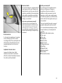
operating instructions.
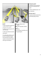
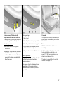
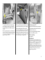
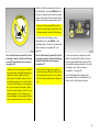
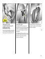
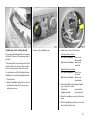
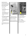
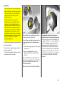
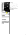
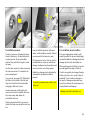
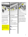
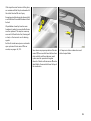
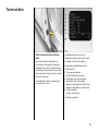
Ele ctronic data acquis ition in toll
systems 3
O n vehicles w ith heat-reflecting w indscreens 3 , mount the chipcard for
electronic data ac quisition and billing in
the b lack shaded zone of the windscreen
on the left or the right behind the interior
rea r-v iew m irror – see illustration. If the
chipcard is mounted outside this zone,
malfunctions may occur in data
acquisition.
48
Steering wheel with rem ote control 3
Radio 3, radio telephone 3 and
infotainment system 3 functions can b e
op erated using the buttons on the steering
wheel.
Mobile te lephones and radio
equipment (CB) 3
Obtain ad vice on p redetermined
installation loc ations for the external
antenna and equipment holder and way s
of using dev ices w ith transmission power of
more than 10 Wa tts. We recom mend that
you consult your Vauxhall Authorised
Repairer, who will have consoles and
various installation k its and install them in
accordance with regulations.
Requirements to ensure trouble-free
opera tion:
Only use the hands-free equipment to
make telephone calls whilst driv ing . This
can also be a distra ction when driving.
Please observ e country-specific laws.
The Vauxhall installa tion instructions and
the operating guidelines p rov id ed by the
telephone manufa cturer m ust be observed
when fitting and operating a m ob ile
telephone. Failure to d o so could invalida te
the vehicle’s operating perm it (EU Directiv e
95/54/EG).
z Professionally installed ex terior aerial to
ob ta in the max imum range possible
z Maximum transmission power 10 W
z Installation of the telephone in a suitab le
spot (see note on pag e 92).
When used in the v ehicle interior, mobile
telephones and radio equipment (C B)
with integrated aerial may cause
malfunctions in the vehicle electronics.
Mobile telephones and radio equipm ent
(CB) should only be used with an aerial
fitted on the vehicle exterior.
49
Keys, Doors,
Bonnet
Re place ment ke ys
The key is a c onstituent of the electronic
immobilizer. O rd ering keys from a Vauxhall
Authorised Repairer g uarantees problem free op eration of the electronic
immobilizer. You will av oid unnecessary
costs, difficulties with insurance comp anies
when processing claims and problems
asserting wa rranty claims.
Locks – see page 212.
Door locking and unlocking
From outside
Mechanically – see page 5,
ra dio frequency rem ote control – see
page 52,
central locking system – see page 54.
From inside
Push down or pull up lock button. To
prevent the driver from being inad vertently
lock ed out, the button on the driver’s door
cannot b e depressed when the d oor is
op en.
50
Child safety locks
Use the child safety lock whenever
child ren are occupying the rear seats.
Failure to do so may lead to injuries or
endanger life. Vehicle p assengers should
be informed accordingly.
Push latc h on rear door lock d ow nwa rds:
Door cannot be opened from inside.
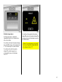
Ele ctronic imm obilize r
The sy stem checks whether the vehicle m ay
be sta rted using the key that has been
inserted. If the k ey is recognised as
"authorised" the vehicle can be started.
To act ivat e:
Switch off eng ine, turn key to position o
and remove.
To deacti vate:
Turn key to position I I (ignition on); the
engine can then b e started.
Dea ctivation is not possib le in any other
way , so keep spare key accessible in a safe
place!
Control i nd icator for imm obilizer
When the ignition is switched on, the
control indicator A lights up briefly. If the
control indicator flashes when the ignition
is on, there is a fault in the immobilizer
sy stem. The engine cannot be started:
1. Turn key to o in starter switch and
rem ove.
2. Reinsert key in starter sw itc h.
3. Then repeat starting procedure.
If the control indicator A continues to
flash, try to start the engine using the spare
key and consult a workshop. We
recommend your Vauxhall Authorised
Repairer.
If c ontrol indicator A lig hts up after the
eng ine has started, there is a fault in the
eng ine electronic s or the automatic
transmission; see page 150.
Not e
The immobilizer does not lock the doors.
Therefore, after leaving the v ehicle a lways
lock it and switch on the Vaux hall alarm
system 3; see pag es 54, 59.
The Car Pass contains all of the vehicle’s
data and should therefore not be kept in
the vehicle.
Hav e y our Car Pass on hand when
consulting a Vauxhall Authorised Repa irer.
51
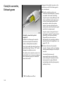
Radio rem ote control 3
The rad io remote control is integrated in
the k ey.
Used to op erate:
z central locking system,
z mechanical anti-theft locking system ,
z boot lid (Saloon),
z Vauxhall ala rm system 3 .
It is also possible to close the windows and
sun roof 3 using the remote control unit.
The remote control has a range of approx.
3 metres. The range ma y b e reduced owing
to sha dowing and reflection of the radio
wav es. To opera te the remote control,
point it at the vehicle.
52
For your conv enience, we recommend that
the central lock ing sy stem alway s be
op erated using the remote control unit.
Handle remote control with care, protect
from moisture and high temperatures and
avoid unnecessary operation.
The light-emitting diode (LED) in the
remote control unit lights up and the
ha zard w arning lamps flash briefly to show
that the rem ote control is op erational.
C entra l lock ing system,
see page 54.
Mechanic al anti -theft locki ng system,
see page 55.
Locki ng the boot lid /t ailga te 3,
see page 56.
Vauxhall ala rm system 3,
see page 59.
Fault
If the central locking system cannot be
opera ted with the remote control, it m ay b e
due to the following :
z The range of the rem ote control has
been ex ceeded.
z The battery voltage of the remote
control unit is too low. Change the
battery in the rem ote control unit.
z The rem ote control ha s b een op erated
frequently in succession outside the
vehicle's reception range (e.g. at too
great a distance from the vehicle).
Resynchronize the remote control.
z If the centra l loc king sy stem is
ov erloaded as a result of repeated
op eration at short interv als, the power
supply is c ut off for approx . 30 second s.
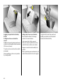
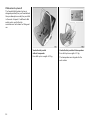
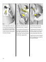
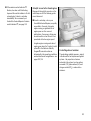
Changing the rem ote control ba ttery
Exchange the battery as soon as the range
of the rem ote control starts to become
reduced.
z Interference from higher-power radio
waves from other sources.
Insert a small screwdriv er in the notch on
the cover and prise it open. Disengage the
remote control from the k ey part and open
the battery cover. Replace the battery,
ensuring that it is inserted correctly (see
page 229 rega rd ing battery type). Close
the rem ote control so that it audibly
engages in the key pa rt.
For c entral locking sy stem operation using
key, see following pages. Have cause of
fault remedied. We recommend that you
consult your Vauxhall Authorised Repairer.
Synchronizing remote contr ol
In the ev ent of malfunctions, synchroniz e
remote control:
1. Switch on ignition; sy stem will then
remain in synchroniz ing mode for
30 seconds.
2. Briefly press button p or q on remote
control unit in ignition.
3. The central lock ing sy stem locks and
unlocks to show that the remote c ontrol
ha s b een sy nchronized.
The battery change must be p erformed
within 3 minutes, otherw ise the remote
control will hav e to be resynchronized.
Make sure that you dispose of old batteries
in accordance with environmental
protection regulations.
53
Not e
z To prevent the driv er from being
ina dvertently locked out, the b utton on
the driver's d oor c annot be depressed
when the door is open.
z If the driver's door is not closed properly ,
the central loc king sy stem will unlock
again immediately after lock ing.
z To loc k the d oors from insid e (e.g. to
prevent unw anted entry from outside),
push down lock button on driv er’s door.
Central locking system 3
For doors, b oot lid/tailgate and tank flap.
Locking
Press button p on rem ote control unit
– or –
turn key in driver's door lock towa rd s rear
of vehic le, then turn it b ack to the vertical
position and remove; alterna tiv ely, when
locking from inside, press the lock b utton
on one of the front doors with the doors
closed.
54
To unl oc k
Press button q on remote control unit
– or –
turn key in driv er's door lock towards front
of vehicle, then turn it back to the vertical
position and remove; alternatively, w hen
unlocking from inside, pull up the lock
button on driver's d oor.
z Locked doors unlock a utoma tica lly if an
accident of a certain sev erity occ urs (to
permit outside assistance). Prerequisite:
Ignition m ust not be switc hed off.
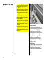
Cl osing window s a nd sun roof 3
The electric door wind ow s 3 and the
electric sun roof 3 can be closed from the
outside: press button p on the rem ote
control while locking or hold the key in the
door locking position until the windows and
sun roof are fully closed.
Care must be taken when operating the
elec tric windows and the sun roof. There
is a risk of injury, especially for child ren,
and a danger that articles could become
trap ped.
Vehicle passengers should be informed
according ly .
Keep a close wa tch on the windows and
sun roof w hen closing them . Ensure that
nothing becomes trapped in them as
they m ov e.
O verload
If the central locking system is ov erloaded
as a result of repeated opera tion at short
intervals, the power supply is cut off for
approx. 30 seconds.
The system is protected by a fuse in the
fuse box; see page 186.
Central locking system,
mechanical anti-theft locking system
Lock ing
All doors must be closed, the driver’s door
must hav e been opened once previously;
press button p on the remote control
again within 10 seconds after lock ing
– or –
turn key in d riv er's door lock towards rea r
of vehicle again within 10 sec onds after
lock ing , then turn it back to the v ertical
position and remove.
To unlock :
Press button q on remote control unit
– or –
turn key in driver's door lock towards front
of vehicle, then turn it back to the vertica l
position a nd remove.
Unlocking is not possible in any other way,
so keep spare key to hand in a safe place!
Lock buttons on all doors are p ositioned
such that doors cannot be opened.
Do not use the system if there are peop le
in the vehicle! The d oors cannot be
unloc ked from inside.
55
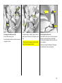
Malfunction in ce ntral locking sys tem
A = Unlock ing the driv er's door
Turn key forw ard in lock pa st
resista nce point as far as it will g o.
Turn key back to v ertical position and
rem ove.
B = Locking the driver's door
With driver's door closed, turn key
towards rear of vehicle until it w ill not
move any further. Turn key back to
vertic al position and remove.
The other doors can be opened and closed
by pulling or pushing the interior lock
button (not possib le if Vauxhall alarm
system enabled beforehand). Have cause
of fault remedied. We recomm end tha t you
consult your Vauxhall Authorised Repairer.
56
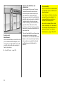
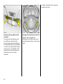
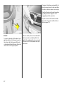
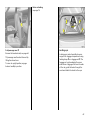
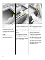
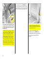
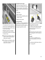
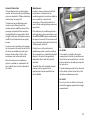
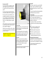
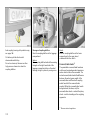
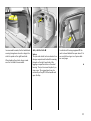
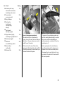
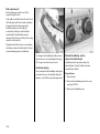
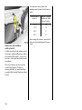
Opening t he ta nk flap
Unlock and open the boot lid/tailgate.
Open the cover on the right-hand side of
the luggag e compartment. The release rod
for the ta nk flap is located behind the servo
motor (a rrow in figure). Push the rod back
with your hand and the ta nk flap can be
op ened . Hav e the cause of the fault
remedied. We recom mend tha t you consult
your Vaux hall Authorised Repairer.
Boot lid, Saloon
To unlock
Press button r on the remote control
– or –
Luggage compartment, Estate
The lock is released by pressing the b utton.
There is a handle on the inside of the
tailgate to facilitate closing the lugg age
compa rtm ent.
O pen luggag e c om part ment
When transporting bulky cargo, do not
drive with the tailgate open or a ja r, as
poisonous exhaust fumes could enter the
passeng er c om partment by mea ns of air
whirls.
Press button x in the instrument p anel
for approx. 2 seconds.
The b oot lid is unlocked and opened
slig htly . When the b oot lid is open the LED
in the b utton x is lit.
There is a hand le on the inside of the boot
lid to assist closing.
Malfuncti on of the electri cal release
Disenga ge the rear seat back rest by
pressing the buttons on the top and then
fold it down onto the seat; see page 70. Pull
the release on the inside of the boot lid; the
lid is unlocked . Have the ca use of the fault
remedied. We recom mend tha t you consult
your Vaux hall Authorised Repairer.
If it is essential to hav e the tailgate op en,
do not open it too wide to ensure that the
number plate can still b e read.
Fitting of accessories on the tailgate will
increa se its weight. I f it becomes too heav y,
it will then not stay open.
6
Open lugg age comp artment
Bulky ob jects should not be transported
with the b oot lid op en or ajar, otherwise
poisonous exhaust fum es may enter the
vehicle as air is swirled around.
Fitting of accessories on the b oot lid will
increase its weight. If it becom es too heavy,
it will then not sta y open.
57
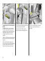
Using the central locki ng system for the
lugg age compa rtment
The c entral locking system and the antitheft locking system for the doors cannot
be locked or unlock ed from the tailgate
lock.
Key slot in lock in horizontal position
Tailgate is lock ed and unlock ed using the
rem ote control or by turning the key in the
driver's door lock.
Key slot in lock in v ertical position
Tailgate remains loc ked even if the vehicle
is unlocked using the remote c ontrol or by
turning the key in the driver's door lock.
This p osition is to be c hosen if the tailgate
is to stay locked.
58
Unlocking the luggag e com part ment
when the d oors are locked w ith the
cent ral lock ing system
Turn the key clockwise as far as possible
from the vertical or horiz ontal p osition. To
safeguard against being lock ed out, the
key cannot be removed.
O nce the tailgate has b een closed a nd the
key turned back to the horiz ontal or
vertical position, the tailgate is lock ed
aga in.
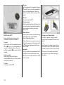
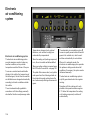
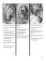
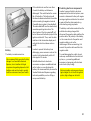
Vauxhall alarm s yste m 3
The system monitors
z the doors, luggage compartment,
bonnet,
z the passenger c om partment,
z the vehic le tilt,
z the ignition.
To activ ate:
All doors, windows a nd sun roof 3 must be
closed; press button p on the rem ote
control unit again within 10 seconds after
lock ing
– or –
turn key in d riv er's door lock towards rea r
of vehicle again within 10 sec onds after
lock ing , then turn it back to the v ertical
position and remove.
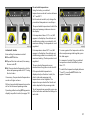
Sw itching system on excl ud ing
m oni toring of the pa ssenger
com partm ent and the v ehicl e t ilt
e.g. if anim als a re to be left in the vehic le.
1. Close boot lid/tailgate and bonnet.
2. Press b utton Ä. LED flashes (for a
maxim um of 10 seconds); see page 61.
3. Close doors.
4. Switch on Vauxhall alarm system . LED
lights up. After approx. 10 sec onds the
sy stem is activated, without monitoring
of the p assenger compa rtm ent or v ehicle
tilt. LED flashes until system is switched
off.
6
59
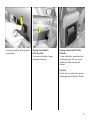
To deacti vate:
Press button q on rem ote control unit
– or –
turn key in driver's door lock towards front
of vehic le, then turn it b ack to the vertical
position and remove.
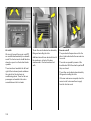
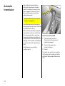
Opening a nd closing Sa loon boot li d
with Vauxhall al arm syst em activ e
O pening and c losi ng Esta te tailga te with
ant i-theft alar m system a ctiv e
1. Press button r on the remote c ontrol.
The boot lid will unlock a nd open slightly.
Monitoring of the passenger
compa rtm ent and v ehicle tilt will be
deactivated.
1. Turn the key clockwise as far as it will go.
The tailgate is unlocked and monitoring
of the passenger compartment a nd
vehicle tilt is deactiv ated.
2. O pen luggag e comp artment.
3. Close the lug gage compartment.
3. Monitoring of the passenger
compa rtm ent, luggage comp artm ent
and v ehicle tilt is switched on again
approx . 10 second s a fter the b oot lid is
closed.
60
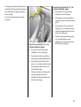
2. Open luggage compartment.
4. Turn the key back to its previous
position. Monitoring of the passenger
compartment, luggage compartment
and vehicle tilt is ac tiv ated after app rox .
10 seconds.
After the first 10 second s of Vauxhall alarm
sy stem activation:
z LED flashes
= System on,
z LED lights up for
approx . 1 second = Switch-off.
If a system fa ult occ urs, consult a
work shop. We recom mend y our Vauxhall
Authorised Repairer.
The system’s integ ra ted self-diagnostics
allow s faults to be quickly remedied.
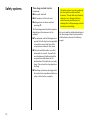
Ala rm
O nly a certain num ber of a la rm s are
allowed to be triggered while the Vauxhall
alarm system is switched on (this number is
stipula ted b y law).
The alarm takes the form of
z an acoustic signal (horn, 30 seconds)
and
z a visual sig nal (haz ard warning lamps,
5 minutes) 1 ).
The alarm can b e stopped by pressing
button q (disable Vauxhall alarm sy stem)
or pressing button p on the remote
control.
Light emit ting d iode (LED)
During the first 10 seconds of Vaux hall
alarm system activation:
z LED lights up
=
Test, switch-on
delay,
z LED flashes
=
Door, tailgate,
bonnet open
or system fault
1)
Varies from coun try to coun try on a ccount of
nationa l regu la tion s.
61
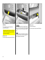
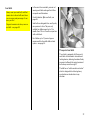
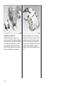
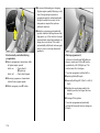
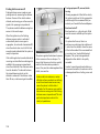
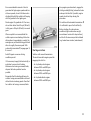
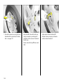
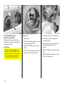
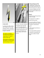
The b onnet is held open automatically. To
close the bonnet, lower it slow ly and allow
it to fall into the lock und er its own weight.
C heck that the b onnet is locked in position
by pulling at its front edge. If it is not
eng aged, repeat the procedure.
Any d irt or snow on the bonnet can slid e
down when it is opened and block the air
inlet; see page 133.
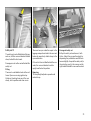
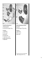
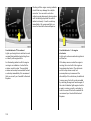
Bonnet
To open the bonnet, p ull the release lever
/ located below the instrument panel on
the d riv er’s side. The bonnet w ill then be
unlock ed and will partially open. R eturn the
release lever to its original position.
62
There is a safety catch on the underside of
the bonnet ab out a hand breadth to the
rig ht of the radiator grille centre as view ed
from the front: lift this upwards and op en
the bonnet.
Seats, Interior
Se at adjustment
see p ages 5, 6.
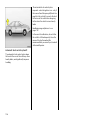
Seat pos ition
Adjust driver's seat such that with the
driver sitting upright the steering wheel is
held in the area of its upper spokes with the
driver's a rms slightly b ent.
The passenger seat should be as far back
as possible, with the backrest upright.
Disregard can lead to injuries which
could be fa tal. Vehicle passengers
should be informed ac cord ingly .
63
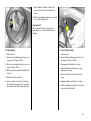
Head restraint position
He ad res traints, Saloon
The c entre of the head restraint should be
at eye level. If this is not possib le, ad just to
the highest position for extremely tall
people, or to the lowest position for
extremely short people.
To fold down passenger’s seat backrest
(lugga ge comp artm ent enlargement – see
page 68), remove head restraint. To do so,
relea se the two springs by pressing them
and deta ch the hea d restraint.
Disreg ard can lead to injuries which
could be fatal. Vehicle p assengers
should be informed accordingly.
Setting , see page 7 and the next p age.
64
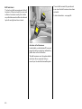
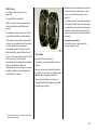
Rear c entre head r estra int 3
If the centre rear seat is unoccupied, the
hea d restraint can be removed to improve
visibility. Release both springs b y pressing,
detach the head restraint and pla ce it in
luggage compa rtm ent on the left-hand
wheel housing.
The centre head restraint must be fitted if
the centre rear seat is occupied.
Head restraints , Es tate
To fold d ow n the p assenger’s seat backrest
(Lugga ge c om partment enlargem ent, see
page 70), remove the head restraint. To do
so, release the two sp rings by pressing
them and detach the head restraint. See
page 64, Fig ure 7353 V.
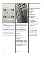
Rear outer head restrai nts
To fold down: press button, head restraint
automatically folds forward. To ra ise, push
head restraint up and enga ge a ud ib ly.
Rea r centre hea d rest raint
If the centre seat is unoccupied, the head
restra int ca n be pushed all the w ay down
to improve visib ility . Push the head
restra int forward and down
simultaneously.
Centre armre st 3
If the centre seat is occupied , set the head
restra int to the first or second position
according to the height of the passenger.
To access the stowage compa rtm ent in the
centre armrest, press the button at the top
and open the lid.
The armrest can be raised. When fold ed
down from the raised position the armrest
eng ages in the horizontal position. To
lower the a rm rest fully: press the button on
the bottom .
65
To adjust inclination at rear:
mov e switch 1 upwards/d ow nw ards at rear
Ele ctrically adjustable front se ats 3
Care must be taken when operating the
elec trically adjustab le sea ts. There is a
risk of injury, p articularly for children,
and a danger that articles could become
trap ped.
To adjust long itudinal position:
mov e switch 1 forw ards/backw ards.
To adjust height:
mov e switch 1 up/down.
Keep a close watch on the seats when
adjusting them.
To adjust backrest:
mov e switch 2 forw ards/backw ards.
Vehicle passengers should be informed
according ly .
O perate switch until desired seat position is
reached. Seat position – see p age 63.
Before leaving the vehicle, remove the
ig nition key.
After a djusting the seat, adjust the heig ht
of the seat belt; see page 82.
Adjustment
The seat p osition can be adjusted by
means of switches on the outboard side of
the seats.
To adjust inclination at front:
move switch 1 upwards/downwards at
front.
66
Position memory 3 for electr ically
adj ust able driv er’s seat and mi rrors 3
Three different seat and mirror setup s ca n
be stored (e. g. for three drivers).
Storing settings:
Ready for operation:
3. Adjusting exterior m irrors, see page 8.
z With driver's d oor open or ignition
switched on.
4. Press memory button M and p osition
button 1 simultaneously.
z For approx. 30 seconds after the driver's
door has been c losed or the ignition
switched off. Op erational readiness is
prolonged if system is operated within
these 30 second s.
5. Set position buttons 2 and 3 in the sam e
way .
1. Adjust seat.
2. Adjusting interior m irror, see pa ge 8.
Retriev ing settings:
Press and hold down position button 1, 2
or 3 until the stored seat and mirror
positions 3 are set.
O verload
If the sy stem is electrica lly overloaded, the
power supply is autom atically cut off for a
short tim e.
Fault
If the electric drive fails, adjust seats
ma nually.
Adjust in longitudinal direction using crank
handle inc luded in vehicle tools – see
pag es 179, 180. Insert crank handle as
show n in illustration a nd turn.
The sy stem is protected by a fuse in the
fuse box – see page 184.
For reasons of safety, a djustment stops
immed iately if the position button is
relea sed or one of the setting buttons is
op erated.
67
Luggage compartment extens ion,
Saloon
Folding d own the cover behind t he
arm rest
Fold down the centre armrest onto the seat
cushion, turn the handle anti-clock wise and
tilt the c ov er forward.
The outer seats can continue to be used for
passengers.
After repositioning , lock cov er in position
by turning handle.
68
Fold ing down t he rear seat back rests
Plac e the belt buc kles in the storage
pockets in the seat cushions.
Unlock one or both of the rear seat
backrests using the pushbuttons on top
and fold it down onto the sea t cushion.
Engage rear seat back rests audibly into
position.
When repositioning rear sea t bac krest, pull
seat belt forwa rd so that it is not trapped.
In v ehicles with centre three-point seat
belt 3: press button (on left-hand belt
buckle). Belt will retract fully.
Notes on loading
see p age 74.
Fold pa ssenger seat 3
Remove the hea d restraint; see page 64.
Tilt passenger seat backrest forward by
lifting the release lever.
To move to upright position, engage
back rest audibly in position.
Lashing eyes
Lashing eyes make it possible to secure
cargo in the luggage compartment using
lashing straps 3 or a luggage net 3 . The
luggage net can be adapted to secure
small items of lugg age: fold over the ends
of the net, guide the hooks through the
mesh and attach the hooks to the eyes.
69
Luggage compartment enlargeme nt,
Estate
The catch slides completely to the left and
a red marking becomes v isible.
Folding d own the rear sea t bac krests
The outer head restraints must not b e
upright when the rear sea t backrests are
folded down, otherwise they ma y be
dam aged when the front seats are
adjusted.
Unlock one or both of the rear seat
backrests using the pushbuttons on top.
Fold the outer head restraints forw ard and
push the centre head restraint down; see
page 65.
Slide the driver a nd passeng er seats
forward. Unlock the rear seat back rests by
pressing the slide catch on top of the
back rest in the direction of the arrow.
70
Fold rear seat back rest down onto seat
and p ress it down until it lock s into
place (A).
To rep osition: Slide driver and passenger
seats slig htly forw ard. Press the ba ckrest
down firmly (A), unlock it (B), and place it
upright.
Before repositioning the rear seat ba ckrest,
mak e sure that the red mark ing on the slid e
catch on top of the backrest is visible; see
page 70, Fig ure 13455 V.
When repositioning rear sea t bac krest, pull
seat belt forwa rd so that it is not trapped.
Fold pa ssenger sea t 3
Remove the head restraint; see page 64.
When repositioning, lock the rear seat
backrests audibly into plac e on both sides
by pressing the slide catch on top of the
backrest in the direction of the a rrow. The
catch slides b ack to its centre position and
the red marking is no longer v isible.
Tilt passenger seat back rest forwa rd by
lifting the release lever.
To mov e to upright position, engage
bac krest audibly in p osition.
Not es on load ing
see page 74.
Lashing eyes
Lashing eyes make it possible to secure
cargo in the luggage compartment using
lashing straps 3 or a luggage net 3 . The
luggage net can be adapted to secure
small items of cargo: fold over the ends of
the net, guide the hooks through the mesh
and a tta ch the hooks to the eyes; see
pag e 69, Figure 7344 V.
71
Luggage compartment cover 3
To close:
Pull the handle back to its stop and engag e
the c ov er in the retainers at the sid es.
Do not place any heavy or sharp-edged
objects on the cover.
To open:
Deta ch the cover from the retainers and
push it tow ards the seat b ackrest.
Rem oving
Push the cov er forward towards the seat
backrest.
Pull folded-together cover towards the rear
into the two short guides on the rails as far
as it will go.
Pull the cover tog ether with the guides
rearwards ag ainst spring force, as shown in
the figure. Tw ist the cover with the two
guid es upwards and remove it by pushing
it forwa rd ; see Fig ure 7532 V.
Fitti ng
Follow the steps in rev erse order to reinstall
the cover, ensuring that the short guides
eng age prop erly in the rails.
If individual ribs slip out of the short guides
when the cover has been remov ed:
1. Detach all rib s from the two guides b y
pressing the locking devices.
2. Insert the ribs in the right and left-hand
rails simultaneously with the flattened
ends facing up. Push the cover forward.
3. Insert the short guid es in the rails from
above against spring force.
72
Safety net 3
The safety net ca n be fitted behind the rear
seats or, with the rear seat backrest folded
down, b ehind the front seats.
Passeng ers m ust not be carried behind the
safety net.
Fitting
There are tw o installation holes in the roof
frame: O pen covers using ignition key .
Attach net (working from one of the rear
doors), loc k in position and close covers.
There are two ey es und er the ca rp et in the
lugg age compa rtm ent and in the rea r seat
backrests respectively: attach straps in the
eyes and tension.
If the net is to be installed behind the rear
seats, the rear seat ba ckrest must be
up right a nd locked in position.
St owage of safety net
Roll up the sa fety net and secure it with
Velcro. Unlock the rear seat bac krests by
depressing the pushb uttons and tilt them
forward slig htly . Suspend the safety net (in
its protective cover) in the recesses on the
right and left behind the rea r seat back rest.
Rem oving
Tilt strap length adjusters upwa rd s a nd
unhook strap.
73
z The w arning tria ngle 3 and first-aid kit 3
must a lways be freely accessible.
z Do not place any objec ts in front of the
rear window or on the instrum ent panel.
They a re reflected in the glass, obstruct
the driver's v iew a nd will be thrown
through the vehicle, for instance in the
event of heavy braking.
z No objects must be placed in the area in
which the airbags inflate, as they could
cause injury when the airbags are
trig gered.
Notes on loading the vehicle
z Heav y objec ts in the lug gage
com partment should be placed as far
forward as p ossible against the rear seat
backrests or, if the rear seat backrests
are folded down, ag ainst the front seat
backrests. If objects are to be stacked,
the heav ier objects should be placed at
the bottom. Unsecured objects in the
lugga ge com partment would be thrown
forward with great force in the event of
heavy braking, for examp le.
z Secure heav y objec ts with lashing
straps 3 atta ched to the lashing eyes;
see page 69. If heavy loads slip when the
vehicle is braked heavily or driven
around a bend, the handling of the
vehicle may chang e.
74
z Sa loon: Loose objects in the luggage
compa rtm ent should be secured against
slipping using a lug gage net – see
page 69.
z Estate: Always fit the safety net when
transp orting objects in the luggage
compa rtm ent; see page 73.
z If objects are being transp orted in the
luggage compa rtm ent, the rear sea t
back rests m ust be locked in place 3
(red marking on the slide catch on top
of the b ackrest no longer v isible); see
pages 68, 71.
z Do not a llow the load to protrude ab ov e
the upp er edge of the rear seat
back rests, or above the upper ed ge of
the front seat b ackrests if the rear seat
back rests a re folded down.
z Bulk y objects should not be transported
with the tailgate/boot lid open.
Otherwise, poisonous exhaust fumes
could enter the vehic le. I n addition, the
numb er plate is only clearly
distinguishable and c orrectly lit if the
tailgate is closed.
z Weights, payload and roof loa d – see
page 222.
z Driv ing with a roof load – see p ages 140,
143, 168, increases the sensitivity of the
vehicle to cross-winds and has a
detrimenta l effec t on vehicle handling
owing to the vehicle’s higher centre of
gravity.
Disregard of these notes c an lead to
injuries which ma y be fatal. Vehicle
passeng ers should be inform ed
accordingly.
Acc essory sock et
The socket in the c entre console, i. e. the
cigarette lighter sock et, c an be used to
connect electrical accessories. There is a n
add itional accessory sock et 3 in the centre
console below the rear air vents. The
sockets are op erational when the ignition is
switched on. If the engine is off, the battery
will be discharged .
The accessory soc ket 3 in the centre
console under the rear air vents shuts off
automatically after app rox . 15 minutes to
prevent the battery from becoming
discharged .
Cigarette lighte r ) 3
Behind a shtray c ov er below stow age
compartment or radio 3.
Press ashtray cover to op en.
Press ciga rette lighter with ignition
switched on. Sw itches off automatically
and ejects when element is g low ing.
Withdraw c igarette lighter.
Do not dam age the soc kets by using
unsuitable plugs.
The maximum power c onsumption of
electrical ac cessories m ust not ex ceed
120 w atts.
Do not connect any current-delivering
acc essories, e.g. electrical charging
devices or b atteries.
Electrical ac cessories connected to the
socket must c om ply with the
electromagnetic compatibility
requirements la id d ow n in DI N VDE 40 839,
otherwise v ehicle malfunctions may oc cur.
Depending on the vehicle equipment level,
the socket may be covered over.
75
Ashtrays
To be used only for ash and not for
combustible rubbish.
Disreg ard c an lead to injuries which may
be fatal. Vehicle pa ssengers should be
informed accordingly.
Ashtray, front
The c ov er opens w hen pressed a t the top.
76
To empty :
Push the small ca tch to the right (arrow in
figure). The ashtray insert will raise slightly.
Gra sp the insert by the trim plate and lift
out.
Fitting
Insert ashtray insert and lock into place by
pressing on surfa ces at left and right. The
latch engages autom atically.
Ashtray, rear
In the rear d oor trims.
The cover opens when pressed at the top.
To empty: op en ashtra y, press spring and
rem ov e a shtray.
Stow age compartments
in the door trims
Stowage compartments 3 in the
backrests
To access press button on stowage
compartment and open.
To open, pull back the compartment cover
using the grip recess. The cov er ca n be
opened or be pulled rearwa rd s a nd
removed .
Sun visors
Use the sun v isor to protect from glare by
pulling it d ow n and swivelling it to the side.
77
Safety systems
Three-stage re straint system
Comprising:
z three-point seat belts
z belt tensioners a t the front seats
z airbag sy stems for driver a nd front
passenger 3.
The three stag es are a ctivated in sequence
depending on the seriousness of the
accident:
z The automa tic seat belt locking devices
prevent the belt strap from being pulled
out and thus ensure that the v ehicle
occupants are retained in their seats.
z The front seat b elt buckles are p ulled
downwards. As a result, the seat b elts
are instantaneously tightened and the
occupants are made aware of the
deceleration of the vehicle at a v ery ea rly
stage. This reduces the stress placed on
the body.
z The airbag sy stems a re also triggered in
the ev ent of serious accidents and form a
safety cushion for the occupants.
78
The airbag systems serve to supp lement
the three-point seat belts and belt
tensioners. The seat belts must therefore
always be worn. Disregard of these
instructions may lea d to injuries or
endanger life. Vehicle p assengers should
be informed accordingly.
Be sure to read the detailed descriptions of
the three-stage restra int system and the
child restraint system on the following
pag es!
Seat belts
Alwa ys wea r your seat belt, and that
means also in urb an traffic and when
you are a rear seat passenger. It can
save y our life!
Pregnant women m ust alwa ys wear a
seat belt – see page 82.
In the event of an accident, persons not
wearing sea t belts enda ng er their fellow
oc cup ants and themselves.
Control indica tor X for sea t belts, see
page 26.
Sea t belts are desig ned to be used by only
one person at a time. They a re only
suitable for children aged up to 12 or
sma ller than 150 cm if used in conjunction
with a child seat.
For children up to 12 y ears of age we
recommend the Vauxhall child restraint
sy stem – see pa ge 94.
Three-point seat belts
The vehicle is equipped with three-point
seat belts with automatic retrac tors and
locking d evices, allowing freedom of body
mov ement although the spring tensioned
belts always ensure a snug fit.
The belt has a " vehicle sensitive retra ctor"
which is designed to lock during hea vy
acc eleration or deceleration in any
direction.
79
The seat belts remain fully opera tional
even w hen the belt tensioners ha ve been
actuated.
Belt tens ioners
The front seat belts are equip ped w ith belt
tensioners. If there is a head -on or rear-end
collision of a certain severity, the buckles
are pulled downward and the shoulder and
lap b elts are tig htened in an instant.
Further information – see page 84.
Actuati on of belt tensioners
is ind icated by control indicator v; see nex t
page. Actuation m ay also be ind icated by
yellow ta bs on the belt buckles.
The belt tensioners must be replaced after
activation. We recommend that you
consult y our Va ux ha ll Authorised Repairer.
80
The system’s integ ra ted self-diagnostics
allow s faults to be quickly remedied. Hav e
your Car Pass on ha nd when consulting a
Vauxhall Authorised Repairer.
Imp or tant
z Accessories and other objects must not
be affixed or placed within the action
zone of the belt tensioners a s this may
result in injury if the belt tensioners are
triggered.
z Do not mak e any modifications to the
components of the belt tensioners, as
this will render the v ehicle unroadw orthy.
Cont rol indic ator v for belt t ensioners
The b elt tensioners are monitored
electronic ally together with the airbag
systems. Their operationa l status is
indicated by control indicator v in the
instrument panel. When the ignition is
switched on, the control indicator lights for
approx. 4 seconds. I f it does not light, does
not go out after 4 seconds or lights while
driving, there is a fault in the b elt tensioner
system or the airbag systems; see pag e 89.
There is a possibility that the belt
tensioners or the airbag sy stems will not be
triggered in the event of an accident.
Imp roper handling (e. g. removal or
installation) could cause the belt
tensioners to be triggered. Risk of injury!
z The belt tensioner and airbag sy stem
control electronics can be found in the
centre console area. In order to av oid
malfunctions, do not store mag netic
objects in this a rea.
z We recom mend that you have the front
seats removed by a Vauxhall Authorised
Repairer.
z The belt tensioners only actuate once.
Please replace belt tensioners that have
been triggered. We recom mend tha t you
consult your Vauxhall Authorised
Repairer.
z Applicable safety directives must always
be ob served when disposing of the
vehicle. For this reason, d isposal should
be done by an authorised recy cling
company. We recommend that you
consult your Vauxhall Authorised
Repairer.
Hav e the cause of the fault remed ied. We
recom mend tha t you consult your Vauxhall
Authorised Repairer.
81
Using the belts
Fitting seat bel ts
Pull the belt out of the retractor and guide
it across the body , making certain that it is
not twisted.
Insert the la tch plate into the buckle. The
back rest must not be tilted too far back,
since this would affect the opera tion of the
seat b elts; the recommended tilting angle
is app rox . 25°. The lap b elt must lie straight
and fit snug ly against the body . Tighten
the la p belt at frequent intervals whilst
driving by tugging the diagonal pa rt of the
belt.
82
O n pregnant women in particular, the
lap belt must be positioned as low as
possible ac ross the pelv is so as not to put
too much pressure on the abdomen.
Bulk y clothing prevents the belt from fitting
prop erly. The belt must not rest against
ha rd or fragile objects in the pockets of
your clothing (e.g. ballpoint pens, keys,
spectacles) because these could cause
injury. Do not place any objec ts (e.g.
ha ndb ags) between the belt a nd your
body.
Height adjustm ent
of seat belt upper anchora ge p oint:
1. Do not adjust whilst driving.
2. Pull b elt out slig htly.
3. Front seat b elts: Press button down or
slide belt guide up.
Rear seat belts: Press belt guide and
slide it upwards or downwards.
4. Set desired height.
5. Allow to loc k audibly into p osition.
Adjust height such that the belt p asses
over the wearer's shoulder and rests
against the shoulder. It must not pass over
the neck or upper arm.
Rem oving t he b el t
To remove the belt, d epress the red
pushbutton on the buckle; the b elt will
retract automatically.
Three- point seat belt 3 on centre
rear seat
S aloon
Use the latch plates to pull the belt out of
the retractor behind the back rest. Insert
the lower latch plate in the left-hand buckle
(identifiable by small pushbutton). Holding
the upper latch plate, g uide the belt across
the shoulder a nd pelvis, m aking certain
that it is not twisted, a nd insert the latch
plate in the right-hand buckle (red
pushb utton).
6
83
To remove belt, depress red pushbutton on
belt buckle. The belt will retra ct
automatically a nd will position itself ready
to hand on the b ackrest.
To enlarge luggag e compartment, depress
sma ll pushbutton on left-hand b uck le using
a ballpoint pen or the like. The belt will
retract fully. Fold down backrests onto seat
cushion.
Lap b elt
In centre of rea r seat: to ad just the length,
press the top of the latch plate.
Estate
Dra w belt out of retractor and guide ac ross
shoulder and pelvis, ma king certain that it
is not twisted, and insert latch plate in belt
buckle.
Plea se check all parts of the b elt system
occasionally for dama ge a nd correct
operation. Rep la ce damaged pa rts. In case
of an ac cident, please replace
overstretc hed belts and triggered belt
tensioners. We recom mend consulting y our
Vauxhall Authorised Repairer.
The belt can only be pulled out of the
retractor when the rear seat backrests are
prop erly locked into position; see page 68.
Testing the belts
Do not mak e a ny alterations to the belts,
their anchorages, the automatic retrac tors
or the belt b uck les.
Mak e sure that b elts are not da maged or
trapped by sharp-edged objec ts.
84
Vauxhall Full Size airbag s yste m
The Vauxhall Full Size airbag system
comprises several individual systems.
Front a irbag system
The front airb ag system is triggered in the
event of a serious accident involving a
frontal impa ct and forms sa fety cushions
for the driver and front passenger. The
forward movement of the driver a nd front
passenger is check ed a nd the risk of
injuries to the up per body and head
thereby substantially reduced.
Si de airba g system 3
The side airbag sy stem is triggered in the
event of side-on collisions and forms sa fety
cushions for the driver and front passenger
in the respective front door area. The risk of
injury to the upp er body in the event of a
side impact is thereby substa ntially
reduc ed.
85
Exception:
Passenger sea t with seat occupancy
recognition system 3 . The seat occupancy
recognition system deactiva tes the
passenger front and side airbags if the
passenger seat is unoccupied or a
Vauxhall child restraint system with
transponders 3 has been fitted to the
passenger seat. S eat occupa ncy
recognition – see p age 90. Vauxhall child
restraint system w ith transponders 3, see
pag e 94.
Examples of events triggering the front
airbag sy stem:
Vauxhall Full Size airbag s yste ms 3
z seat occ upa ncy rec og nition 3,
Front airb ag
The front airbag system is identified by the
word AI RBAG on the steering wheel and
above the glov e c om partment.
z the control indicator for Va ux ha ll child
restraint systems y with transponders 3
in the courtesy lamp.
The front airbag system comprises:
z an airbag with inflator in the steering
wheel and a second one in the
instrum ent panel
z the control elec tronics with impact
sensor
z the a irba g system s control indicator v in
the instrument panel,
86
The front airb ag system will be trigg ered :
z depending on the severity of the
accident
z depending on the type of impact
z within the range shown in the illustration
z indep endently of the side airb ag
system 3.
z Impact against a non-y ielding obstacle:
the front airbags are trigg ered at low
vehicle speed.
z Impact against a yield ing obstacle:
(such as another vehicle): the front
airbags are only triggered at a hig her
vehicle speed.
When trigg ered , the front airbags inflate in
milliseconds to form a safety cushion for
the d riv er and front passenger. The
forward movement of the front seat
occupants is c hecked, thereby
sub stantially reducing the risk of injury to
the upp er body and hea d.
No im pairment of view will occur, because
the a irba gs inflate and deflate so quic kly.
The front airbag sy stem provides
optimum p rotection when the seat,
back rest and head restra int are correctly
adjusted: Adjust the driver's seat
according to the occupant's height such
that with the driver sitting upright the
steering wheel is held in the a rea of its
upper sp ok es with the d riv er's arms
slightly bent. The pa ssenger seat should
be as far back as possible, with the
back rest upright (see pa ges 5, 63). Do
not place the head, body , hands or feet
on the c ov ers of the airbag sy stems.
The front airbag sy stem will not be
triggered in the ev ent of
z the ignition is switched off
z minor frontal collisions
z accidents in which the vehicle overturns
z collisions involving a sid e or rear impac t
where it would not be of benefit to the
occupants.
6
Do not place any objects in the area in
which the airb ags inflate. Im portant
inform ation – see page 92.
The three-point seat belt must be
correctly fitted – see page 82.
87
Seat belts must therefore always be
worn. The front airbag system serves to
supplement the three-point seat belts. If
you do not wea r your seat belt you risk
being seriously injured, or even thrown
from the vehic le, in the ev ent of an
accident.
The belt helps to keep you in the correct
seating position, in which the front
airb ag system will provide you with
effective protection in the event of an
accident.
In addition, the front airb ag sy stem will not
be triggered for the front passeng er in versions with seat occ upa ncy recognition 3 if
z the front passenger's seat is unoccupied
z there is a prop erly fitted Va ux ha ll child
restraint system with transponders 3 .
Seat oc cup ancy recognition, see
page 90. Vauxhall child restraint system
with transponders 3, see page 94.
Side airb ag 3
The side a irb ag system is identified by the
word AIRBAG on the outb oa rd sides of the
front seat backrests.
The side a irb ag system c om prises:
z an airbag with infla tor in the back of the
driver's a nd front passenger's seat
respectively
z the control electronics
z the side impact sensors
z the airbag systems c ontrol indicator v in
the instrum ent panel,
z seat occ upa ncy rec og nition 3,
z the control indicator for Va ux ha ll child
restraint systems y with transponders 3
in the courtesy lamp.
88
The side airbag sy stem will be triggered:
z depending on the sev erity of the
accident,
z depending on the ty pe of im pact,
z within the range shown in the illustration
on the driver's door or front passenger
door,
z ind epend ently of the front airbag
sy stem.
Ex ception: Passenger seat with seat
occupancy recognition system 3. The
seat occupancy recognition system
deac tiv ates the passenger front and side
airbags if the pa ssenger seat is
unoccupied or a Vauxhall child restraint
sy stem with transp onders 3 has been
fitted to the passenger seat. Seat
occupancy recognition – see page 90.
Vauxhall child restra int system with
tra nsponders 3 , see page 94.
The side airba gs will not be triggered in the
event of
z the ig nition is sw itc hed off
z fronta l collisions
z accidents in which the vehicle overturns
z collisions involving a rear impac t
z collisions involving a side imp act outside
the passenger cell.
In addition, the side airbag system w ill not
be triggered for the front passenger in versions with seat occupancy recognition 3 if
z the front passenger's sea t is unoc cup ied
When triggered, the sid e airbag inflates in
milliseconds to form a safety cushion for
the d riv er or front passenger in the
respective door area. This substantially
red uces the risk of injury to the upper body
in the event of a sid e-on collision.
There m ust be no objects in the area in
which the airbag inflates or in the area
between the seat back s a nd the vehicle
body. Do not place the hand s or arm s on
the covers of the airbag system s.
Important information – see page 92.
The three-point seat belt must alway s be
correctly fitted – see page 82.
z there is a properly fitted Vauxhall child
restraint system with transpond ers 3.
Seat occupancy recognition, see
page 90. Va ux ha ll c hild restraint system
with transp onders 3, see pag e 94.
Control i nd icator v for airbag systems
The front airb ag system and the side
airbag system 3 are monitored
electronically tog ether w ith sea t
oc cup anc y recog nition 3 a nd the belt
tensioners. Their operational read iness is
shown by control indicator v in the
instrument panel.
When the ignition is switched on, the
control ind icator lights for approx .
4 seconds. If it d oes not light, does not go
out after 4 sec onds or lights while driv ing,
there is a fault in the a irb ag systems, seat
occupancy recognition 3 or the belt
tensioners; see page 81. There is a
possibility tha t the systems will not be
triggered in the ev ent of an accid ent.
Have the c ause of the fault rem edied.
We recom mend that you consult your
Vauxhall Authorised Repairer.
The sy stem’s integrated self-diagnostics
allows faults to be quickly remedied. Have
y our C ar Pass on hand when consulting a
Vauxhall Authorised Repairer.
89
Seat oc cupancy recognition 3
The seat occupancy recognition system
deactivates the front and side airbags for
the front passenger if the front passenger's
seat is not occupied or a Vauxhall child
restraint sy stem with transponders 3 is
fitted on the front pa ssenger's sea t.
The c ontrol indicator for seat occupancy
recognition is located in the c ourtesy lamp .
If this control indicator lights up after
the ig nition is switched on for approx.
4 seconds, the v ehicle is equipped with
seat occupancy recognition – see p age 91,
Fig. 11383 T.
If a Vauxhall c hild restra int system with
transponders 3 is installed , this control
indicator rem ains on after the ignition ha s
been switched on a s soon as the system
has detected the seat. Only then can the
child restraint system b e used on the
passenger seat.
90
In addition, vehicles with seat occupancy
recognition can be identified b y the sticker
on the front p assenger’s seat.
Vauxhall c hild restraint system s w ith
tra nsponders 3 are detected
autom atic ally when fitted on the front
passenger’s seat ac cord ing to the
instructions. When one of these child
restra int system s is used on the front
passenger’s seat, the front a nd side airbag
sy stems for the front p assenger’s seat are
deactiv ated. Be sure to pay attention to
the seat occupa ncy recognition control
indica tor 3; see page 91.
Only Vauxhall child restraint systems
with transpond ers 3 ca n be fitted on the
front passenger’ s seat; the use of
sy stems without transpond ers poses a
danger to life.
Vauxhall child restraint systems with
transponders 3 are identified by a stick er.
If the child restraint system is not fitted
correctly or the transponders are faulty,
the control indic ator flashes. C heck that
the child restraint system is fitted correctly.
Fitting child restraint system w ith
tra nsponders 3 – see pages 94 to 95.
If the control indicator does not illumina te
with a correctly installed child restraint
sy stem there is a fa ult - risk of fatal injury to
the child. Fit child restraint system to rear
seat. Ha ve c ause of fault remedied. We
recommend that you consult your Vauxhall
Authorised Repairer.
Cont rol indica tor y for Vauxha ll
child rest raint systems w ith
tra nspond ers 3
The p resence of a Vaux hall child restraint
system w ith transponders 3 is indicated
after the ignition has been switched on by
permanent illumination of the control
indicator y in the courtesy lamp, as soon
as the seat occupancy recognition system
has detected the child restraint system.
If no Vaux hall child restra int system with
tra nsponders 3 is installed, the control
indica tor must neither light nor flash, as
this indicates that the airbag system s on
the passenger side would not be triggered.
Have the ca use of the fault rem edied. We
recommend that you consult your Vauxhall
Authorised Repairer.
If the Va ux ha ll child restraint system with
tra nsponders 3 ha s b een fitted
according to the instructions, the control
ind ic ator for Vauxhall child restraint
sy stems with transponders in the
courtesy lamp must light up w hen the
ignition is switched on.
If the control indicator does not
illuminate whilst driv ing , the airb ag
sy stems ha ve not b een deactiv ated on
the passenger side. Risk of fatal injury . In
this case, fit child restra int system to rear
seat. Ha ve cause of fault remedied . We
recommend that you consult your
Vauxhall Authorised Repairer.
If the control indicator is not lit while
driving, the airbag systems for the front
passenger seat have not been
deactivated . C hild’ s life is endangered. Fit
the c hild restra int system on the rear seat.
Hav e the cause of the fault remed ied. We
recom mend tha t you consult your Vauxhall
Authorised Repairer.
91
Im portant
z Acc essories and other objects must not
be affixed or placed in the a rea in which
the airbags inflate a s they could cause
injury if the airbags are trig gered.
z Do not p la ce a ny objects between the
airb ag systems and the vehicle
occ upa nts; d ang er of injury .
z The belt tensioner and airbag sy stem
control electronics c an be found in the
centre c onsole area. I n ord er to av oid
malfunctions, do not store magnetic
ob jects in this area.
z Do not stick a ny thing on the steering
wheel, instrument p anel and front seat
backrests in the v ic inity of the airbags
and seat areas or cover them with other
materials.
z Use only a dry cloth or interior cleaner to
clean the steering wheel, instrum ent
panel and front seats. Do not use any
aggressiv e c leaning agents.
z Only protective covers which are
approved for your Omega w ith side
airb ag 3 may be fitted on the front
seats. When fitting the protective c ov ers,
make sure that the airba g units on the
outboard sides of the front seat
backrests are not c ov ered.
z The airbag system s are triggered
independently of each other depending
on the severity of the a ccident and the
ty pe of im pact.
92
z Each airbag can be trig gered only once.
O nc e triggered, an airbag must be
rep laced without delay. We recomm end
that you consult your Vauxhall
Authorised Repairer.
z Persons weig hing less than 35 kg should
only travel on the rea r seats. This d oes
not apply to c hildren who are trav elling
in child restraint sy stems with
tra nsponders 3 .
z The speeds, d irections of m ov ement and
deform ation p roperties of the v ehicles,
and the properties of the obstac le
concerned, determine the severity of the
accident and triggering of the airbags.
The degree of da mage to your vehic le
and the resulting repair costs alone are
not indicative tha t the criteria for
triggering of the airbags were m et.
z In vehicles with seat occupancy
recognition 3, do not p la ce a ny heav y
objects on the front passenger's seat
otherwise the a irb ag systems for the
front passenger's seat may be trig gered
in the event of an a ccident.
z Do not perform any altera tions on the
components of the airba g system, as this
would rend er the vehicle unroadw orthy.
The system s can be trig gered abruptly
and c ause injury if they are handled
improperly.
z We recomm end that you entrust rem ov al
of the steering wheel, instrument panel,
front d oor trim panels and front seats to
a Vauxhall Authorised Rep airer.
z Applicable safety directives must alwa ys
be observed when disposing of the
vehicle. For this reason, disposal should
be done by an a uthorised recycling
compa ny . We recommend that you
consult y our Vauxhall Authorised
Repairer.
z In vehicles with seat occupancy
recognition 3, to prevent malfunctions
do not use protective covers or seat
cushions on the front pa ssenger's seat.
z When using a Vauxhall c hild restraint
sy stem with transponders 3 on the front
passeng er's seat, in order to prev ent
malfunctions, no objects (e. g. pla stic
sheet, stickers or heated mats) may be
placed und er the child restraint sy stem.
Child restraint systems and other heavy
objects must not be transported on the
laps of vehicle occupants, risk of fa ta l
injury. Child restraint systems with
tra nsponders 3 transported in this way
may prevent the pa ssenger airbag
sy stems from trig gering in vehicles with
seat occupancy recognition 3.
Vehicles with front pa ssenger airbag ca n
be id entified by the w ord AIRBAG above
the glove compartment and the warning
sticker on the side of the instrument p anel,
visible when the passenger door is open.
Vehicles with side airbag 3 : No c hild
restraint system 3 may be fitted on the
front passenger's seat; risk of fatal injury.
A vehicle with side a irba gs can be
identified b y the word AIRBAG on the
outboard sides of the front seat backrests.
Sea t occupancy recognition 3 – see
page 90.
Use of child restrai nt systems 3 on front
passenger's seat in v ehi cles w ith air bag
systems 3 and wit hout seat occupanc y
recogniti on 3
Use of chil d restraint syst em s 3 on front
passenger’s seat in v ehi cles w ith air bag
systems 3 and with seat occ up ancy
rec ognition 3
Vehicles with front passenger airbag 3
but without side airbag 3 : Rea r-fac ing
child seats (safety cradle and child
safety seats for weig ht ra nges 0 and I –
see following pages) must not be fitted
on the front p assenger’s seat, danger to
life. Forward-facing child seats (sa fety
seats for weight ranges I, II a nd III – see
following pag es) can be fitted on the
front passeng er's seat p rov ided that the
la tter is moved as far back as it will go.
O nly Vaux hall child restraint sy stems
with tra nsponders 3 can be fitted on the
front passenger’s seats. Use of system s
without transpond ers poses a d ang er to
life.
The seat occupancy recognition system
detects Vauxhall child restraint sy stems
with transponders 3 and switches off the
front and side airbag system s for the front
passenger's seat. Seat occupancy
recognition – see p age 90.
Vauxhall child restraint systems with
transponders 3 can b e identified by the
sticker on the child restraint sy stem.
93
Child restraint sys tem s 3
The Vauxhall child restraint system is
designed specifica lly for y our Va ux ha ll and
thus prov ides optimum safety for your child
in the event of im pact. I f a different child
safety seat is used, follow the
manufacturers' instructions for fitting and
use.
Va uxhall sa fety crad le
without t ransponder
From b irth up to a weig ht of 10 kg.
94
Vauxhall safety crad le w ith transponders
From birth up to a w eight of 10 kg.
The tra nsponders are integrated in the
seat cushion.
Vauxha ll Fix chi ld safety seat
wi thout transponder
From birth up to a weight of 36 k g.
Va uxhall child safety seat without
transponder
From b od y weight of 91 ) kg to 36 k g.
Com prising:
1 Seat backrest,
2 Safety support
3 Seat cushion
4 Securing console
5 Height adjuster cushion
6 Ad apter with belt buckles
7 Reboard b elt
Comprising:
1 Seat bac krest,
2 Sa fety support
3 Seat cushion
1)
Us e of the system is not recom mend ed for
child ren weighing les s th an 11 kg .
95
Vehicles with front pa ssenger airbag ca n
be id entified by the w ord AIRBAG above
the glove compartment and the warning
sticker on the side of the instrument p anel,
visible when the passenger door is open.
Use of child restrai nt systems 3 on front
passenger's seat in v ehi cles w ith air bag
systems 3 and wit hout seat occupanc y
recogniti on 3
Vehicles with front passenger airbag 3
but without side airbag 3 : Rea r-fac ing
child seats (safety cradle and safety
seats for weight ranges 0 and I – see
following pag es) must not be fitted on
the front p assenger’s seat; d ang er to
life. Forward-facing child seats (sa fety
seats for weight ranges I, II a nd III – see
following pag es) can be fitted on the
front passeng er's seat p rov ided that the
la tter is moved as far back as it will go.
96
Vehic les with sid e airbag 3: No child
restra int system 3 m ay be fitted on the
front passenger’ s seat.
A v ehicle with side airbags can b e
identified by the word A IRBAG on the
outboard sides of the front seat b ackrests.
S eat occupancy recognition 3 – see
pag e 90.
Not e
z Children und er 12 years or under 150 cm
tall should only trav el in an ap prop ria te
child sa fety sea t.
z When transporting c hildren, use the child
restra int system s suitable for the child's
weight.
z Ensure that the c hild restraint system is
fitted correctly .
z The covers of the safety c ra dle a nd
safety seat can be wiped clean.
Use of child restrai nt systems 3 on front
passenger’s seat in vehicles wit h airbag
systems 3 a nd
wi th seat occupanc y recognit ion 3
Only Vauxhall child restraint systems
with transp onders 3 can be fitted on the
front passenger’ s sea ts. Use of systems
without transponders poses a danger to
life.
The seat occupancy recognition system
detects Vaux hall child restraint sy stems
with transponders 3 and switches off the
relevant airbag sy stems to protect the
child. S eat occ upa ncy rec og nition – see
page 90.
Vauxhall c hild restraint system s w ith
tra nsponders 3 can be identified by the
sticker on the child restraint system.
z Do not stick any thing on the child
restra int systems and do not cover them
with any other m aterials.
z Only allow child ren to enter and exit at
the side fa cing away from the traffic.
z A child restraint sy stem which has been
subjected to stress in an accident must
be replaced.
z You should also ob serve the instructions
on installa tion and use supplied with the
child restraint sy stem.
6
97
Child restraint sys tem :
Vauxhall safety cradle 3 without
trans ponde r
For babies ag ed up to 10 months or
weighing up to 10 k g.
In vehicles with front passenger a irba g 3
or side airbag 3, the safety cradle must
not be fitted on the front passenger's
seat, risk of fatal injury . In this case, fit
the safety c ra dle on the rear seat.
98
Fastening t he chi ld's seat b el t
Plac e child in safety cradle.
Join the two shoulder belts of the sa fety
cradle as shown in the illustration and
engage in belt buckle between the child's
legs.
Ad apting to the child's size
The length and heig ht of the belts on the
safety cradle can be adjusted a ccording to
the child 's size:
To adjust length, p ull b elt strap at rear of
safety cradle or loosen it by pressing the
metal clip.
The belt must fit snug ly a cross the child's
body w ithout being too tig ht.
To adjust height, pull both shoulder belts
towards rear through slots. Then guid e
belts through slots in required position.
Securing in the v ehic le
Raise carrying handle of safety c ra dle.
Plac e safety cradle on seat, with belted
child facing away from the direction of
tra vel.
O pen clip on rear of safety cradle to side.
Move upp er anchorage point of vehicle
seat belt to lowest position – see page 82.
To disengage carrying hand le, press down
and swivel in direc tion of v ehicle seat
bac krest.
Pull v ehicle seat belt out of retractor and
route lap belt through the two guide clips
on the sid e b olsters of the safety cradle.
Route the diag onal part of the vehicle seat
belt around the bac k of the safety cradle
bac krest through the open clip. Tighten
vehicle seat belt and close clip.
Fasten b elt buckle.
99
Child restraint sys tem ,
Vauxhall safety cradle with
trans ponde rs 3
For babies ag ed up to 10 months or
weighing up to 10 k g.
The Vaux hall safety cradle with
transponders 3 can be id entified by a
sticker on the safety cradle – see page 94.
Do not fit a child restraint sy stem on the
front passenger’ s sea t if the vehicle is
equipped with front passenger airbag 3
or side airb ags 3, but d oes not have seat
occ upa ncy rec og nition 3. Otherwise,
there is a risk of fatal injury.
In vehicles with front passenger airbag 3
or sid e airbag 3 and with seat occupancy recognition 3, only Vauxhall child
restraint systems with transponders 3
may be fitted on the front passenger's
seat; using systems without transponders
poses a danger to life.
Sea t occupancy recognition 3 – see
page 90.
Vauxhall c hild restraint system s w ith
tra nsponders 3 may a lso be fitted on the
rear seat.
Fastening t he chi ld's seat b el t
Plac e child in safety cradle.
Join the two shoulder belts of the sa fety
cradle as shown in the illustration and
engage in belt buckle between the child's
legs.
100
Ad apting to the child's size
The length and heig ht of the belts on the
safety cradle can be adjusted a ccording to
the child 's size:
To adjust length, p ull b elt strap at rear of
safety cradle or loosen it by pressing the
metal clip.
The belt must fit snug ly a cross the child's
body w ithout being too tig ht.
To adjust height, pull both shoulder belts
towards rear through slots. Then guid e
belts through slots in required position.
Securing in the v ehic le
Raise carrying handle of safety c ra dle.
Plac e safety cradle on seat, with belted
child facing away from the direction of
tra vel, as shown in the illustra tion.
Move upper anchorag e point of vehicle
seat belt to lowest position – see pag e 82.
Ad just seat b ackrest as described on
page 87.
Fasten belt buckle.
Pull vehicle seat belt out of retractor and
route lap belt through the two guid e clips
on the side bolsters of the safety cradle.
6
101
Child restraint system,
Vauxhall Fix child re straint system 3
without trans ponde r
Modula r system for va rious weight ranges:
z Weight ranges 0 and I: From birth up to
a w eight of 18 kg. O nly fit with child
facing awa y from direction of trav el.
z Weight range I: For weight of 9 kg to
18 kg; it is ad visa ble to only use weight
range I for weights of 11 kg and above.
Always install facing direction of travel.
O pen clip on rear of safety cradle to side.
Route the diagonal part of the vehicle seat
belt around the back of the safety cradle
back rest through the op en clip. Tig hten
vehic le seat belt and close clip.
To disengage c arrying ha ndle, press down
and swivel in direction of vehicle sea t
back rest.
102
z Weight range II: For weig ht of 15 kg to
25 kg . Always install facing direction of
tra vel.
z Weight range III: For weight of 22 kg to
36 kg . Always install facing direction of
tra vel.
Child restraint sys tem ,
Vauxhall Fix child s afety seat 3,
Weight range 0 and I:
From birth up to 18 kg
Place safety sea t as follows on one of the
outer rear seats such that the child only
faces a way from the direction of travel.
Securing in the v ehic le
Fit reboard belt 3 to head restraint of
relev ant front seat as shown. Remove head
restra int – by relea sing spring catches by
pressing a nd withd rawing head restra int,
see p age 64.
Feed long belt strap with buckle between
seat backrest and seat, slot into Reboard
belt latch and tighten.
6
Push Reboard belt fully upwa rd s over both
struts of the head restraint, as shown in the
illustration. Engage head restraint in
fix tures on seat backrest.
103
Place the height adjuster cushion in one of
the rear seat bench seating positions. Press
the rounded side of the supplied adap ter
between the back rest and the seat bench,
as shown in the figure, and engage both
belt buckles in the adapter.
104
Before fitting, ad apt child safety seat to
child's size as necessary – see page 106.
Insert latch p la te of Reboard belt into
buckle at rear of safety seat backrest.
Only m ount safety seat facing aw ay from
the direction of travel and lock the latch
plates audibly into the belt buckles on the
securing c onsole. Tug on the sea t to check
that the belt has engaged properly .
Tighten Reboard belt at belt adjuster. The
child safety seat back rest must rest against
the front seat and the securing console
must be positioned fully on the rear seat.
To a djust the front seat, loosen the reboard
belt. After adjusting the seat, retighten the
belt using the belt adjuster.
Fasteni ng the child's sea t belt
Place child in sa fety sea t.
Join latch plates of belts on safety seat and
enga ge in b uck le.
To adjust leng th, pull belt strap a t front of
safety seat or loosen it b y lifting the metal
clip.
The belt must fit snugly across the child 's
body without b eing too tight.
Remov ing the safety seat
Undo belt buckle on rear of safety sea t and
depress red pushbuttons on both belt
buckles on the ad apter. Detac h safety seat
from ad apter.
Before rem oving the ad apter, disengage
the belt b uck les from underneath.
105
Ada pting t o the child’s size
Adjust height of belts on safety seat
according to child's siz e: detach p adding
from rear of backrest, d etach vertic al belts
from metal clip and pull them out in the
forward direction. Route belts through
other slots a nd attach them to metal clip.
Resecure pad ding at rear of backrest.
106
Ad justing child safety seat on securing
console to fit child’s size: Unscrew the four
knurled screws and nuts from the underside of the securing console. Detach the
securing console a nd slot it in the desired
position on the stud bolts (3 possib le
settings). S crew in the knurled screw s a nd
nuts.
Child restraint sys tem ;
Vauxhall Fix child s afety seat 3,
Weight range I:
9 kg to 18 kg 1)
The c hild must face the direction of travel
when a safety seat is placed on one of the
outer rear seats.
The safety seat for weight range I is also
ava ilab le as a separate sy stem. S ee the
third column on this page for details on its
use.
To change from w eig ht range 0 and I to
weight ra ng e I
Remove the safety seat by following the
steps for fitting weight ranges 0 and I in
reverse order.
Turn safety seat over and loosen the four
knurled screws and nuts in the und ersid e of
the securing console. Deta ch securing
console.
Securing in the vehicle
Place the height adjuster cushion in one of
the rea r seat bench seating positions. Press
the rounded side of the supplied ada pter
between the ba ckrest and the seat benc h,
as show n in the figure, and engage both
belt buckles in the adapter.
6
Raise clamp 1 and rem ove from belt loop.
Pull belt buckle from seat c ushion. Detach
integral belt from sa fety sea t.
Keep a ll parts in a safe place.
Rota te securing console 180° a nd slot it
onto the two stud bolts (3 possible
settings). S crew in the knurled screw s a nd
nuts.
1)
Use of th e s ys tem is n ot recomm ended fo r
children weig hing less tha n 11 kg.
107
Mount safety seat in direc tion of travel only
and lock both latch plates on securing
console audibly into belt buckles on
adap ter. Tug on the seat to check that the
belt has engaged properly .
Fastening t he chi ld's seat b el t
Plac e child in safety seat.
Insert diag onal and lap belts of vehicle
seat belt into belt guides on safety base.
Insert safety base into recesses on seat
cushion.
Insert latch p la te of vehicle sea t belt in
buckle.
Move the upper anchorage point of the
vehicle seat belt to its low est position.
Height ad justment, see p age 82.
Remov ing the safety seat
Depress the red pushbutton for each
buckle on the a dapter. Detach the sa fety
seat from the adap ter; see pag e 105,
Fig. 10397 A.
Before rem oving the ad apter, disengage
the belt b uck les from underneath.
108
Child restraint sys tem ,
Vauxhall Fix child s afety seat 3,
Weight range II:
15 kg to 25 kg
The c hild must face the direction of travel
when a safety seat is placed on one of the
outer rear seats.
The safety seat for weight range I I is also
ava ilab le as a separate sy stem. S ee the
third column on this page for details on its
use.
To change from w eig ht range 0 and I to
weight ra ng e I I
Remove safety seat b y reversing seq uence
of op erations for fitting weig ht ra nge
0 and I.
Turn safety seat over and loosen the four
knurled screws and nuts in the und ersid e of
the securing console. Deta ch securing
console.
Securing in the vehicle
Place the height adjuster cushion in one of
the rea r seat bench seating positions. Press
the rounded side of the supplied ada pter
between the ba ckrest and the seat benc h,
as show n in the figure, and engage both
belt buckles in the adapter.
6
Raise clamp 1 and rem ove from belt loop.
Pull belt buckle from seat c ushion. Detach
integral belt from sa fety sea t.
Keep a ll parts in a safe place.
Rota te securing console 180° a nd slot it
onto the two stud bolts (3 possible
settings). S crew in the knurled screw s a nd
nuts.
109
Mount safety seat in direc tion of travel only
and lock both latch plates on securing
console audibly into belt buckles on
adap ter. Tug on the seat to check that the
belt has engaged properly .
Fastening t he chi ld's seat b el t
Plac e child in safety seat.
O pen flap on outer height adjuster on
safety seat, insert belt and close flap.
Insert latch plate of vehicle seat belt in
buckle.
Withdraw pin and a djust belt position by
mov ing slide upwa rds or downwards. Allow
pin to lock into p osition.
The lap b elt of the vehicle seat belt must
pass through the two guides on the seat
cushion.
Ad just the upp er anchorage point of the
vehicle sea t belt so that the b elt runs along
the shortest route to the height adjuster on
the child safety seat. Height adjustm ent,
see p age 82.
The seat b elt must pass over the child's
shoulder, never over the neck or upper
arm.
Remov ing the safety seat
Depress the red pushbutton for each
buckle on the a dapter. Detach the sa fety
seat from the adap ter; see pag e 105,
Fig. 10397 A.
Before rem oving the ad apter, disengage
the belt b uck les from underneath.
110
Child restraint sys tem ,
Vauxhall Fix child s afety seat 3,
Weight range III:
22 kg to 36 kg
To change from w eig ht range I or II t o
weight ra ng e I II
Remove safety seat b y reversing seq uence
of opera tions for fitting weight range I or II.
The c hild must face the direction of travel
when a safety seat is placed on one of the
outer rear seats.
Use a screw driver to unscrew the outer
screws connecting the sa fety seat backrest
and cushion. Remove stud bolts from sea t
cushion, working from the inside. Separate
safety seat backrest from cushion.
The safety seat for weight range I II is also
ava ilab le as a separate sy stem. S ee the
nex t page for details on its use.
Securing in the vehicle
Place the height adjuster cushion in one of
the rea r seat bench seating positions. Press
the rounded side of the supplied ada pter
between the ba ckrest and the seat benc h,
as show n in the figure, and engage both
belt buckles in the adapter.
6
Keep a ll parts in a safe place.
111
Remov ing the safety seat
Depress the red pushbutton for each
buckle on the a dapter. Detach the sa fety
seat from the adap ter; see pag e 105,
Fig. 10397 A.
Before rem oving the ad apter, disengage
the belt b uck les from underneath.
Mount safety seat in d irection of trav el and
lock b oth latch p la tes audibly into belt
buckles on a dapter. Tug on the seat to
check that the b elt has engag ed p roperly.
Fastening t he chi ld's seat b el t
Plac e child on sea t cushion.
Insert latch plate of vehicle seat belt in
buckle.
The lap b elt must pass through the tw o
guid es on the sea t cushion.
The seat belt must p ass over the child’s
shoulder, nev er over the neck or upper
arm. Adjust the upper a nchorage point
of the v ehicle seat belt according to
child’s size. Height a djustment, see
page 82.
112
Child restraint sys tem ,
Vauxhall child restraint seat 3
without transponder
Modular system for v arious
weight rang es:
z Weight range I: for w eight of 9 kg to
18 kg; it is ad visa ble only to use weight
range I for weights of 11 kg and above.
Always install facing direction of travel.
z Weight range II: for weight of 15 k g to
25 kg . Always install facing direction of
tra vel.
z Weight range III: For weight of 22 kg to
36 kg . Always install facing direction of
tra vel.
113
Child restraint sys tem ,
Vauxhall child s afety seat 3 ,
Weight range I:
9 kg to 18 kg 1)
May be fitted on rea r seat or front
passenger's seat. In the latter case, move
front p assenger's seat a s far bac k as it will
go.
On vehicles w ith side airbag s 3 , no child
restraint system may be fitted on the
front p assenger's seat; risk of fa tal injury.
1)
Use of th e s ys tem is n ot recomm ended fo r
children weig hing less tha n 11 kg.
114
Fastening t he chi ld's seat b el t
Plac e the sa fety sea t on one of the rear
seats or on the front p assenger's seat,
fa cing the direction of travel only. If it is to
be fitted on the front passenger's seat,
move the latter as fa r back as it will go.
Plac e child in safety seat.
Insert safety base into recesses on seat
cushion.
Move the upper anchorage point of the
vehicle seat belt to its low est position.
Height ad justment, see p age 82.
Insert diag onal and lap belts of vehicle
seat belt into belt guides on safety base.
Insert latch p la te of vehicle sea t belt in
buckle.
Child restraint sys tem ,
Vauxhall child s afety seat 3 ,
Weight range II:
15 kg to 25 kg
May be fitted on rea r seat or front passenger's seat. In the la tter case, move front
passenger's seat a s far b ack as it will go.
On vehicles w ith side airbag s 3 , no child
restraint system may be fitted on the
front p assenger's seat; risk of fa tal injury.
Fastening t he chi ld's seat b el t
Plac e the sa fety sea t on one of the rear
seats or on the front p assenger's seat,
fa cing the direction of travel only. If it is to
be fitted on the front passenger's seat,
move the latter as fa r back as it will go.
Plac e child in safety seat.
Insert latch plate of vehicle seat belt in
buckle.
The lap b elt of the vehicle seat belt must
pass through the two guides on the seat
cushion.
Adjust the upper anchorag e point of the
vehicle seat belt 3 so tha t the belt runs
along the shortest route to the height
adjuster on child safety seat. H eight
adjustment – see page 82.
O pen flap on outer height adjuster on
safety seat, insert belt and close flap.
Withdraw pin and a djust belt position by
mov ing slide upwa rds or downwards. Allow
pin to lock into p osition.
The seat b elt must pass over the child's
shoulder, never over the neck or upper
arm.
115
Child restraint sys tem ,
Vauxhall child s afety seat 3 ,
Weight range III:
22 kg to 36 kg
May be fitted on rea r seat or front
passenger's seat. If it is to be fitted on the
front passenger's seat, move the latter as
far back as it will go.
In vehicles with side airbags 3 no child
restraint system may be fitted on the
front passenger seat.
The safety seat for weight range I II is also
ava ilab le as a separate sy stem. S ee third
column for details on its use.
116
To change from w eig ht range I or II t o
weight ra ng e I II
Remove safety seat b y reversing seq uence
of op erations for fitting weig ht ra nges I
and II.
Detach both belt ends from the metal clip
at rear of safety seat backrest and rem ove
belt.
Use a screw driver to unscrew the outer
screws connecting the sa fety seat backrest
and cushion. Remove stud bolts from sea t
cushion, working from the inside. Separate
safety seat backrest from cushion.
Keep a ll parts in a safe place.
Fastening the child 's seat belt
Place the sea t cushion on one of the rear
seats or on the front passenger's seat,
facing the direction of travel only . In the
latter ca se, move front passenger's seat as
far ba ck as it will go.
Place child on seat cushion.
Insert latch p la te of vehicle sea t belt in
buckle.
The lap belt must pass through the two
guides on the seat cushion.
The seat b elt must pass over the child’s
shoulder, never over the neck or upper
arm. Adjust the upper anchorage point
of the vehicle sea t belt a ccord ingly .
Height ad justment, see page 82.
He ad res traints
Safety acce ssorie s 3
Do not a tta ch objects or components that
are not app rov ed for y our O mega to the
head restraints, since they can reduce the
protection prov ided b y the head restraints
and could be catapulted uncontrollably
through the v ehicle in the event of hard
braking or an acc id ent.
The wide ra nge of Vauxhall accessories
allows you to equip your O mega in
acc orda nce with your own wishes. In
add ition to safety accessories, item s for
improving comfort a nd a complete ra nge
of vehicle care p roducts you will find m any
articles w hich w ill be of g reat va lue to you
when need ed.
Activ e front seat head rest raints 3
In the event of a rear-end impact, the
active head restraints on the front seats
autom atic ally tilt forwards. The head is
more effectively supported by the head
restra int and the d anger of whiplash injury
is reduced.
Exterior mirrors
For the safety of pedestrians, the exterior
mirrors will swing out of their normal
mounting p osition if they are bumped with
sufficient force. Reposition the m irror by
apply ing slight pressure to the mirror
housing.
Asphe rical exterior mirror
Increa ses the field of v ision. S lig ht
distortion means that it is somewhat
difficult to estimate the distance b etween
the v ehicle and those behind it.
"Genuine Vaux hall Parts a nd Accessories"
guarantee high quality a nd accurate fit.
Y our Vauxhall Authorised Repa irer will be
happy to advise you, for ex ample with
regard to:
z Vauxhall child restra int system s,
z Tow ropes
z Tow rods
z Jump leads
z Spare bulb kit
z Spare fuse kit
z Halogen fog la mps
z Mud flaps
z Magnetic la mp
z Wa rning triangle
z First-aid kit
z First-aid kit (cushion)
117
Lighting
Exte rior lights
Headlamp range adjus tme nt ?
Turn light switch:
7 = O ff
8 = Parking la mps
9 = Dipp ed or m ain beam
Ma nua l hea dlam p range ad justment 3
Adjust headlamp range to four stages of
vehicle loa ding with dipp ed beam switched
on: turn knurled w heel to desired p osition.
Dip ped beam , main b eam and head la mp
flash – see p age 14.
C orrect a djustment of the head lamp rang e
reduc es dazz le for other road users.
In positions 8 and 9, the tail lamps and
numb er plate lamps are also lit.
z Front seats occupied
=
0
z All seats occupied
=
1
Vehicles with daytime running lig hts 3:
With the ignition on and the light switch
on 7, d ip ped beam without instrum ent
illumination is on.
z All seats occupied a nd
lug gage compartment
=
2
For driving a broa d – see pa ge 121.
Turn signal indicators, hazard
warning lights, side marker lamps
see p age 15.
118
z Driv er’s seat oc cup ied and
lug gage compartment =
3
Autom atic hea dlam p ra nge ad just ment 3
Regula tes headlam p range on vehicles
with Xenon headla mps. Control indicator
? lights briefly when the ig nition is
switched on. I f it does not light or lights
while driv ing , a fault has occurred. Have
the c ause of the fault rem edied
immediately . We recomm end that y ou
consult your Vauxhall Authorised Repairer.
In vehicles with chec k control 3, the
warning "Headlamp Range Adjustment –
Headlight" app ears in the display in the
event of a fault; see p age 40.
Fog lamps > 3
Courte sy lamp 0
On =
Off =
C om es on when a door is op en. O nce the
door is closed, the lamp switches off after a
slight delay 3 or when the ignition is
switched on 3.
Press>
Press > ag ain
Control indica tor > in instrum ent panel.
Fog tail lamp r
On =
Off =
Press r
Press r a gain
or switch light off
Control indica tor r in instrum ent panel.
The fog tail lam ps on the vehicle are
deactiv ated w hen towing a ca ra van/
tra iler.
To keep the courtesy lam p on, pull the light
switch.
Automatically regulated centre
console lighting 3
S potlight in housing of interior m irror.
Day lig ht-dependent, automatically
regula ted centre console lighting with
ignition switched on.
Re ve rsing lamps
Come on when reverse gear is engaged
and ignition is switched on.
119
Instrument illum ination k
Re ading lamps, front
Reading lamps, rear
Com es on with the exterior driving lamps
(ex cept the day tim e running lights).
Brightness c an be adjusted using the
knurled wheel.
Reading lamps at left and right individ ually
op erable. With ignition turned on:
On
O ff
Light comes on
when a rea r door
is opened
Inform ation display illum ination
On =
Off =
Press button
Press button again
= S witch to rear
= S witch in centre
= S witch forward s
Lights up w hen ignition is switched on.
When vehicle lights are on, brightness can
be adjusted with knurled wheel.
Luggage compartment lighting
Glove com partm ent lam p
Safeguarding the batte ry
Glove c om partment is illuminated when lid
is open and ignition on.
To prevent the battery from becoming
discharged , certa in energy consumers,
such as the courtesy lam p, switch off
automatically 30 minutes after the ignition
is switched off.
Cigarette lighte r
and as htray illumination
Lights up w hen ignition is switched on.
120
C om es on when the boot lid/tailga te is
opened.
Headlamps when driving abroad
The a sym metrical dipped bea m increases
the field of vision on the passenger side of
the la ne.
This causes glare for oncom ing traffic if the
vehic le is driven in countries where traffic
drives on the opposite side of the road.
To avoid glare, switch both dipp ed b eam
head la mps to sy mmetric al dipped beam:
1. Open bonnet.
2. Remove headlamp protective cov er: turn
rotating lock through 90° using a coin
and remov e cover.
3. Remove the hea dlamp c ap.
4. Adjust lever shown in illustration:
Left-hand drive vehicles
Left-hand headlamp = Move lever
downwards
Right-hand headlamp = Move lever
upwards
Right-hand drive vehicles
Left-hand headlamp = Move lever
upwards
Right-hand headlamp = Move lever
downwards
5. Check light/dark limits of d ipped beam
(e.g. in front of a wall):
Horizontal
= S ymmetrical
Angled upwards
= Asymmetrical
6. Pla ce the headlam p cap in position and
close.
7. Refit the headlam p protective c ov er and
secure with rotating lock.
121
Windows, Sun roof
C are must be taken w hen operating the
electric windows 3 a nd electric sun
roof 3. There is a risk of injury,
particularly for children, and a d anger
that articles could b ecome trapped.
Vehicle passeng ers should be inform ed
accordingly.
If there are children on the rear seat,
switch on the child safety sy stem 3 for
the elec tric wind ow s.
K eep a close watch on the windows and
sun roof when closing them. Ensure tha t
nothing becomes trapped in them a s
they move.
Before lea ving the v ehicle, remove the
ignition key in order to p revent
unauthorized opera tion of the wind ow s
and sun roof.
Electric windows 3
Two or four switches in driver’ s d oor: The
front switches operate the driv er and front
passenger windows, while the rear
switches 3 operate the rea r windows.
Additional switches are located in the front
passenger and rear doors.
To operate window in stages, b riefly pull or
press switch. For autom atic opening or
closing , pull or press switch for slightly
longer; to stop wind ow movement, pull or
press switch again.
Sa fet y functi on
If the window glass encounters resistance
abov e the middle of the window d uring
automatic c losing, it is imm ediately
stopped and the w indow opened again.
122
Interruption of p ower supply
Automatic op ening and closing of the
wind ow s is not possible after interruption
of the power supply or a drop in b attery
voltage. Activate the window electronics as
follows:
1. C lose doors.
2. Sw itch on ignition.
3. C lose the window and hold the switch for
at least 5 second s.
4. Repeat for each window.
If the windows do not move easily (e.g. on
account of frost), rep eatedly pull the switch
for the window in question until the window
has been closed in stages.
Chil d safety syst em for rear wi nd ows
Switch b etween the switches in the handle
on the d riv er's door
z To left (red control indicator v isible): rear
wind ows ca nnot be opera ted with the
switches in the rear d oors.
z To right (green control indicator visible):
rear windows can be operated w ith the
switches in the rear d oors.
Leav ing the vehicle
The w indows can still be operated a fter the
ignition has been switched off. O nce the
doors have been closed the windows can
no longer be operated from inside.
C losi ng window s from outside
The windows can b e closed using the radio
remote control: Press button p until the
windows are closed
– or –
Hold the key in the d riv er’s door loc k in the
door locking position until the windows are
closed.
O verload
If the sy stem is overload ed, the power
supply is automatically cut off for a short
time.
The system is protec ted by fuses in the fuse
box – see page 184.
123
To raise:
Set the rotary switch to a position between
l and q; the sun roof will automatically
move to the desired position. When the
switch is in position q the sun roof is fully
ra ised.
To lower:
Turn rotary switch to l .
Posit ion memory
After the ignition has been switched on, the
sun roof can be automatically returned to
its last position b y briefly pressing the
rotary sw itc h.
Ele ctric sun roof 3
Rotary switch between the sun visors.
O peration with ignition switched on:
To open:
Set the rotary sw itc h to a position between
l and ü ; the sun roof will automatically
move to the desired position. When the
switch is in p osition ü the sun roof is fully
opened.
Com fort positi on
Rotary switch locks shortly before
rea ching ü. With the roof in this position,
wind noise is reduced.
To close:
Turn rotary sw itc h to l.
124
Safety func tion
If the sun roof encounters resistance during
autom atic closing, it is im med ia tely
stopped and opened again.
If the roof does not m ov e easily, on account
of frost for exam ple, turn the rotary switch
to l and keep it depressed until the sun
roof is closed.
Sun sha de
The sun shade can be opened and c losed
with the sun roof either closed or raised .
When the sun roof is opened, the sun shade
is a lso opened.
C losi ng sun roof from outside
To close the sun roof using the rem ote
control: Press button p until the sun roof is
closed
– or –
Insert the k ey in the driver’s door lock, turn
it towards the rear of the vehicle and hold
it in that position until the sun roof is closed .
If the sun roof is to rema in open, briefly
press the rotary sw itc h before turning off
the ignition.
Interrup tion of power suppl y
After interruption of the power supply or a
drop in battery voltage the desired sun roof
position is no longer set automatically . The
electronic s of the sun roof must be
rep rogram med as follows:
1. Switch on ignition.
2. If sun roof is closed:
Set rota ry switch to l and hold down for
at least 5 seconds.
If sun roof is open:
Set rotary switch to l, press until sun
roof is closed, and then continue to
hold d ow n rotary switc h for a t least
5 seconds.
3. Set rotary switch to q, press until sun
roof is raised, then set switch to l and
press until sun roof is closed.
4. Set rotary switch to ü and p ress until
sun roof is fully raised . Then set rotary
switch to l and press until sun roof is
closed.
If automatic c losing of the sun roof is not
possible after p rogram ming, repeat steps
3 and 4.
Fault
If the electric d riv e fails, the sy stem is
protected by a fuse in the fuse box – see
page 184. Until the fault is rem edied,
op erate the sun roof as follows:
Push drive cover to rear and remove.
Compress sprung central section of drive
shaft with screw driver and turn drive shaft.
Electric re ar window blind 3
Reduces intensity of sunlight shining onto
rear seats. O peration with ignition
switched on.
Raise blind = Press N
Lower b lind = Press N a gain
Do not opera te blind if there are objects
lying in front of the rear window.
125
Electronic
air conditioning
system
Ele ctronic air conditioning system
Temperature changes d ue to external
influences, such as direct sunlight, are
autom atic ally compensated.
The electronic air conditioning sy stem
provides maximum comfort under any
weather conditions, a t any outsid e
tem perature and at all tim es of the y ear.
When the c ooling unit (cooling comp ressor)
is on, the air is cooled and dehumidified.
To ensure a constant and com fortable
climate in the v ehicle, the tempera ture of
the inflowing air, the air-flow rate a nd the
air distrib ution are cha nged automatically
according to clim atic conditions outside
the v ehicle.
The pollen filter removes d ust, soot, pollen
and spores from the inflowing outside air.
Its activated charcoal coating cleans the
air of odours and p olluting env ironmenta l
gases.
The a ir is a utomatica lly regulated in
accordance with the settings personally
selected for the driv er and passenger sides.
126
When no c ooling or dry ing is required press
the ECO button to sav e fuel – see page 130.
The autom atic air rec irculation system 3
has an air quality sensor to detect harmful
gases in the outside air, in which case it
switches automatically to recirculation.
When set to automa tic mode, the
electronic air c onditioning system prov ides
the op tim um settings under almost all
conditions. If necessary , the system can be
influenced manually.
The electronic air conditioning system is
only fully operational when the engine is
running.
O peration with the cooling unit is only
possible at temperatures above approx.
5 °C . Below this temperature the c ooling
unit (cooling com pressor) switches off
automatically.
Pre-selected temperat ures
Using the knobs, pre-selected
temperatures can be set to va lues between
16 °C and 28 °C.
For the sak e of comfort, only cha nge the
pre selected temp erature in small step s.
The pre-selected temperatures for both the
driver a nd passeng er sides are shown in
the display.
If a temperature below 16 °C is set, LO
appea rs in the disp la y: the electronic air
conditioning system runs constantly with
maximum cooling. The temperature is not
regulated .
Autom atic m ode
Basic setting for max imum comfort:
z Press AUTO button.
z Open all front air v ents and, if necessa ry ,
the rear vents 3.
z Set the pre-selected tempera ture for the
driv er and passenger sides to 22 °C using
the turn knob s.
If nec essary , the pre-selected tem perature
can be set higher or low er.
Different pre-selected temperatures can be
set for the driver a nd passeng er sides.
O perating without cooling (ECO ap pears in
display) may affect comfort; see page 130.
If a temperature above 28 ° C is set, HI
appea rs in the disp la y: the electronic air
conditioning system runs constantly with
maximum heating. The temperature is not
regulated .
The pre-selected tem peratures are
retained when the ig nition is sw itched off.
If the pre-selected temperature is
display ed only on the driver’s sid e, the
driver’s side and passenger side
temperatures are set together. The
temperature pre-selected for the d riv er’s
side is adopted for the passenger side.
To once again set the temp erature for the
driver and pa ssenger sid e together, press
the knob again.
For reasons of com fort, the pre-selected
temperatures should not differ by more
than 2 °C .
To switch the temperature display between
°C and ° F: press the AUTO button for
app rox . 3 seconds.
To set tem peratures separately, press one
of the two knobs and m ake the settings for
each side.
127
Air vents
All air vents (except the rear air v ents 3)
are controlled automatically in a utomatic
mode. The front air vents should therefore
alway s b e open: turn the knurled wheels
upwards.
The a ir vents are loc ated to the left a nd
right of the instrument panel and above
the c ontrols for the electronic air
conditioning system . Those for the rear
passengers are located in the centre
console betw een the front seats.
128
The air flow can b e d irected as desired by
tilting a nd swiv elling the slats.
Ad ditional air outlets a re loca ted in front of
the windscreen, in front of the door
wind ow s a nd in the front and rear foot
wells.
Rear a ir vents 3
The pre-selected temperature set for the
driver’s side is directed to the rea r seats via
two v ents.
The vents are opened by means of the
knurled w heel. With the wheel in p osition 7
they are closed.
The air flow can be directed as desired by
tilting and swivelling the slats.
If the rear seats are unoccupied, close the
rear air vents to increase the a ir supply
from the front air v ents.
Manual settings
Under certain circumstances (e.g. iced-up
or misted-up w indows), the functions of the
electronic air conditioning system can be
influenced manually.
Manual settings are stored when the
ignition is switched off.
Mak e m anual settings as follows when
nec essary :
6
Air re circulation system
The a ir recirculation sy stem prevents the
entry of outside air and the air in the
passenger com partment is circulated .
Manual ai r circula tion mod e
Press button t once. u app ears on the
display .
Air circulation is automatically activated as
soon as the sy stem detects p olluting gases
from the outside air. The circuit is
controlled by an air quality sensor.
The exchange of fresh air is reduced in air
circulation mode. The quality of the
passenger compa rtm ent air deteriorates
whic h may c ause the v ehicle occ upa nts to
feel drow sy . In operation w ithout cooling
the air humidity increases, so the windows
may mist up. Consequently, manual air
circulation should only be run for short
periods of time.
To deactivate electronic a ir circula tion:
press button t again.
To deactiv ate m anual air circula tion:
press button t again.
Autom atic a ir circ ul ation mod e 3
Press button t briefly twice within one
second. t ap pears on the d isplay .
At outside tem peratures below 5 °C the
duration of the air circulation mode is
limited . This prevents the windows from
misting up. Switch to m anual air circ ulation
as necessary.
129
Window dem isting a nd de-icing
Disreg ard of the settings described can
cause the windows to become m isted up
which c an lead to accidents due to lack
of p roper vision.
Press button V . V app ears on the
display.
Tem perature and air distribution are set
automatically and the fan is run at a high
speed to quickly clear ice a nd
condensation from the windows.
To return to automatic m od e: press
button V or AUTO.
130
Hea ted rear wi nd ow,
heat ed exterior m irrors
Press button Ü. Ü a ppears on the display.
O peration w ithout cooling
Press EC O button. ECO appears on the
display.
The rea r window and exterior mirrors will
quic kly be cleared of ic e and condensation.
S witc h on to save fuel. In this mode cooling
(the c ooling comp ressor) is sw itc hed off.
Heating operationa l only with engine
running.
Inflowing air is neither c ooled nor
dehum idified. This restricts the lev el of
comfort provided by the electronic air
conditioning sy stem. This may cause the
windows to mist up, for example.
The heating is switched off automatically
after approx . 15 minutes. To sw itch it off
before that tim e: press button Ü ag ain.
To return to operation w ith c ooling: press
ECO button. ECO goes out.
Air d istributi on
Press one or more of the following b uttons.
The corresponding symbol appears on the
display:
Air flow
Press button x at right or left. x appears
on the display. The selected fan
prog ra mme is indica ted b y bars. The air
flow ra te is increased or reduced as
appropriate.
Residual heat sys tem
M : Air distrib ution to vehicle occupants
via adjustable air vents
front and rear 3.
The bars disappear after a short time. x
gives a reminder of the manual air flow
setting.
Press AUTO w ith the ignition off. AU TO
and the pre-selected temperatures appear
on the display .
K : Air distrib ution to front and
rea r foot a rea.
Within the individual fan prog ra mmes the
air flow is regulated autom atically by
cha ng ing the fan sp eed dep ending on the
temperature selected.
The residua l heat system switches off
automatically when the heat stored in the
cooling system is no longer suffic ient to
hea t the passenger compartment.
To return to a utomatic mode: press AUTO
or with the x buttons select a fourth fan
prog ra mme (4 bars on the display).
To deactivate, switch on the ignition or
press O FF.
s : Air distrib ution to windscreen
and to front door windows.
To return to automatic m od e: press the
appropriate buttons again, or press AUTO .
When the vehicle is stopped and the
ignition off, the hea t still in the cooling
system can be used to heat the pa ssenger
compa rtm ent, for example when stopped
at a rail crossing:
131
Switching off the e lectronic air
conditioning system
Press O FF. O FF appears on the d isplay . All
func tions of the electronic air conditioning
system a re deactivated.
He ated front se ats 3
Heated rear s eats 3
Tw o knurled wheels ß below electronic air
conditioning controls:
Two pushbuttons ß at rea r of centre
console below rear air vents
Turn relev ant wheel to set required heating
level.
O nce the ignition is switched on, seat
hea ting can be activated by pressing
button ß .
The a ir distribution setting remains at the
position last selected.
Control indica tor a bove knurled wheels.
To switch on the electronic air conditioning
system: press OFF or AU TO .
Heating only with ig nition switched on.
132
To switch off, set wheel to B.
On
O ff
=
=
Press ß
Press ß again
C ontrol indicators in pushbuttons.
Gene ral information
Maintenance
If the windscreen m ists up during damp
weather, set the automatic a ir conditioning
system as described in "Window d emisting
and de-icing"; see pa ge 130.
In order to ensure continuously efficient
performance of the electronic air
conditioning system it must b e sw itc hed on
once a m onth for a few minutes,
irresp ective of the weather a nd time of
yea r, with the cooling (cooling compressor)
op erational.
The electronic air conditioning sy stem
func tions most efficiently when the
windows and sun roof 3 are closed . If the
passenger com partment has hea ted up
considerably after a long p eriod in direct
sunlight, briefly op en the windows a nd sun
roof 3 so that the heated air can quickly
escape.
To ensure correct operation, the openings
for the sensors in the control cluster for the
electronic air conditioning system and
between the air outlets in front of the
windscreen must not be obstructed.
When the elec tronic air c onditioning
system is switched on, cond ensa tion will
form and w ill issue from the underside of
the v ehicle.
If the electronic air conditioning sy stem is
not functioning in the usual m anner: press
the A UTO and O FF buttons simultaneously
for approx. 5 sec onds. The servomotors will
be synchronized, during which tim e the fan
will temp orarily switch off.
If a fault occurs in the electronic air
conditioning system, consult a workshop.
We rec om mend your Vauxhall Authorised
Repairer. The system ’s integrated selfdiagnostics allows faults to be quickly
remedied.
The pollen filter with activated charcoal
coating must b e replaced at the
maintenance intervals sp ecified in the
Serv ic e Booklet.
Air intake
The air inta ke – located in the engine
compa rtm ent in front of the windscreen on
the far left as seen from the front – must be
kept free of leav es, dirt and snow to permit
the entry of air.
The water drainage outlet on the other side
of the vehicle must be free of d irt so that
rainwater can drain away freely.
Air outlet
Do not cover the air outlets when storing
items in the luggag e compartment storag e
compa rtm ents.
133
Automatic
transmission
After sta rting the engine and before
shifting into a gea r, depress the brake
pedal, If the brakes are released w hen a
gear is engaged , the v ehicle will "creep".
Nev er ac tuate accelerator and b rake
pedals simultaneously .
Disregard of these instructions may lead
to injuries or endanger life.
Once D has been selected, the economy
driving p rogra mme is operative. Position D
is g enerally ideal for d riv ing.
If the accelerator peda l is depressed gently
and ev enly the transmission w ill shift into
the fuel-saving gears at an early stage.
Manua l gear cha ng ing is required only in
exc eptional cases, such as when autom atic
shifting up is to be avoided or if ad ditional
use is to be m ade of the engine braking
effect.
Select D ag ain as soon as driving
conditions perm it.
Selector lever in P , R and N
P
Park. Rear wheels are locked.
O nly with vehic le stationa ry and
hand brak e engaged.
R
Reverse. O nly engage when
vehicle is stationary .
N
N eutral.
The selector lever can only be moved from
the P position with the ignition switched on
and the foot brake operated (selector lev er
lock).
134
The engine can only be started with lever in
position P or N. When position N is selected,
press foot brake or engage hand brak e
before sta rting.
Gear selector positions D, 4, 3, 2 on
vehicle s with dies el engine
D
Drive position for normal driving
conditions in first to fifth gear.
Do not accelerate during the selection
proced ure.
4
Drive position for driving conditions
requiring first, second, third and fourth
gears.
3
Drive position for first, second and
third gear, e.g. on w inding mountain
roads; the transmission does not shift
into fourth or fifth gea r.
2
Position for max imum braking effect,
e.g. when driving down severe
gradients; the transm ission does not
shift b eyond second gear.
Se lector leve r position D, 3, 2, 1 on
vehicles w ith petrol engine
D
Driv e position for normal driv ing
conditions in first to fourth g ear.
3
Driv e position for d riv ing cond itions
requiring first, second a nd third gea rs.
2
Driv e position for first and second
gear, e.g. on winding mountain roads;
the transm ission does not shift into
third and fourth gear.
1
Position for m aximum braking effect,
e.g. when d riv ing down severe
gradients; the transmission does not
shift beyond first gear.
135
z By mea ns of delayed gear changing
(higher eng ine speeds) following a cold
start, the operating tem perature
programm e quickly and automatically
brings the ca ta ly tic converter to the
temperature required for op tim um
pollutant reduction.
z Adaptive programm es automatically
prevent undesired shifting between the
high gears, e.g. if the vehicle is towing a
carav an/trailer, has a high payload, or is
being driven on inclines. The vehicle
automatically shifts b ack to a lower gea r
when in ov errun on steep downw ard
gradients.
Ele ctronically controlled driving
programme s
z Sporty programm e, tra nsmission shifts
at higher engine speeds:
Switch on
= Tap b utton S
(1 lights up).
Switch off
= Tap b utton S again.
z Economy p rogram me: transmission
shifts a t lower engine speeds.
z Winter prog ra m: press T button.
Winte r program me T
In the ev ent of sta rting-off difficulties on
slippery roads, press button T (can be
operated only in D – T lights up). The
vehicle starts off in third gear.
The winter program is switched off b y:
z pressing b utton T again,
z manually shifting to P, 3, 2 or 1 or to P, 4,
3 or 2,
z holding the accelerator pedal in the
kickdown position for longer tha n two
seconds,
z turning off the ignition.
The winter programme automatically
switched off a t speeds in excess of app rox .
80 km/h.
136
Kickdown
Rocking the car
Manoeuvring the vehicle
When the accelerator peda l is pressed
beyond its resistance point below certain
engine speeds, the transmission downshifts
to a lower gear. Full use is made of engine
power for acceleration.
If it becomes necessary to rock the vehicle
to free it from sand, mud, snow or a hole,
move the selector lever from D to R in a
repeat pattern w hile sim ultaneously
applying light pressure to the accelerator
pedal. Do not race the engine and av oid
sudden acceleration.
To ma noeuv re the vehicle back and forth
during attempts to park or in ga ra ge
entrances, the v ehicle's creeping
mov ement can be utilised by releasing the
brak e pedal.
Engine braking assistance from
motor
To utilize the engine braking effect, selec t a
lower gear in g ood time w hen driving
downhill.
This applies only to the exceptional
circum stances mentioned a bove.
N ever actuate accelerator and brake
pedals sim ultaneously.
Braking is most effective in the lowest gear.
If a gear is selected a t too high a speed, the
transm ission remains in the relevant g ear
until the shift point is rea ched, e.g. as a
result of dec eleration.
137
The tra nsmission no longer shifts
automatically.
Stopping the vehicle
The selector lever can be left in the chosen
gear with the engine running.
Vehicles with p etr ol eng ine
Driving ca n be c ontinued. Second gear is
not availab le:
When stopping on gradients engage hand
brake or depress brake ped al. To prevent
overheating of the transmission, do not
increase engine revolutions to ensure
smooth id ling while standing if a gear has
been selected.
1
2
3
D
N
R
P
Switch off eng ine if stop ping for a lengthy
period, e. g. in traffic jams or at level
crossings.
Before leav ing the vehicle, apply hand
brake, then place selector lever in position
P and remove ignition k ey.
If the ignition key is not rem oved, the
battery may be d ischarged if the vehicle is
then left to stand for a lengthy period of
time.
The ignition key ca n only be remov ed when
the selector lev er is in position P.
138
Fault
Control indica tor A lights when the
ignition is switched on. If it does not go off
after starting or comes on whilst driving,
there is a fa ult in the automatic
tra nsmission or the engine electronics.
In vehicles with check control 3 , the
warning "Autom atic Gearb ox " app ears in
the display in the ev ent of a fault; see
page 40.
=
=
=
=
=
=
=
1st gear
3rd gear
4th gear
4th gear
Neutral position
Reverse g ear
Park position
Hav e c ause of fault remedied. We
recommend that y ou consult y our Vauxhall
Authorised Repa irer.
The sy stem’s integrated self-diagnostics
allows faults to b e q uick ly rem edied.
Vehi cles w ith diesel engine
Driving ca n be continued. If the fault occurs
while driving, the v ehicle will only run in fifth
gear. When the engine is restarted fourth
and fifth gea r are a vailable:
2
3
4
D
N
R
P
=
=
=
=
=
=
=
4t h gea r
4t h gea r
4 th gear
5th g ear
Neutral position
Rev erse gear
Park position
Hav e ca use of fa ult remedied. We
recom mend tha t you consult your Vauxhall
Authorised Repairer.
The system ’s integrated self-diagnostics
allows faults to be quickly remedied.
Inte rruption of power supply
If the v ehicle b attery is flat, the selector
lever cannot be moved out of position P.
If the ba ttery is flat, start the v ehicle using
jump lead s – see page 174.
If the ba ttery is not the ca use of the fault,
relea se selec tor lever:
1. Apply hand brake.
2. Disengage cover from centre console,
rotate cloc kwise throug h 90° and fold
up.
3. Push catch forward with a screwdriver
and move selector lever out of P.
4. Mount cov er back on the centre console
and refit.
Re-selecting P locks the selector lever
aga in. Have cause of power sup ply
interruption remedied . We recommend
that you consult y our Vauxhall Authorised
Repairer.
139
Driving hints
The firs t 1 000 miles/600 km
P ower steering
Driv e y our v ehicle at various speed s. Do
not use full throttle. Never allow the engine
to labour at low rev s.
If the power-assisted steering fails when
being towed with the engine switched off –
the vehicle can still be steered , but
consid erably more force is required.
Make good use of all gears. Depress the
accelerator ped al a ma ximum of around
three quarters of the available p edal travel
in all gea rs.
Do not d riv e faster than three quarters of
maximum speed .
Do not b rake unnec essarily ha rd for the
first 125 miles (200 km).
The inform ation c oncerns the engine and
parts of the power train, e.g . the final drive.
Never coast with engine not running
Many units w ill not function in this situation
(e.g. brake servo unit, power steering).
Driv ing in this ma nner is a danger to
yourself and others.
Brake servo unit
With the engine not running the brake
servo unit is no longer effective once the
brake peda l has been depressed once or
twice. The braking effect is not red uced but
substantia lly grea ter foot pressure is
necessary to stop the vehicle.
140
Driving in mountainous terrain or
with a caravan/trailer
The cooling fan is electrically operated. Its
cooling power is therefore independent of
the engine speed.
S ince a c onsiderab le am ount of heat is
generated at high engine speeds and less
at slower speeds, do not shift down when
climb ing hills whilst the vehic le is still coping
with the gradient in the hig her gear.
Diesel engine: O n gradients of 8 % or more,
do not drive faster than 20 mph (30 k m/h)
in first gear or 30 m ph (50 km/h) in second
gear.
Driving with a roof load
Do not exceed the perm issible roof load;
see pages 168, 222. For reasons of safety,
distribute the loa d ev enly a nd secure it
properly with reta ining straps so that it
cannot slip . Set the ty re p ressure to the
va lue sp ecified for a full load. Do not drive
faster than 75 mph (120 km /h) Check and
retig hten the straps frequently.
Switching off the e ngine
Engine s pe ed
Clutch operation
When you switch off, fans in the engine
compartment may continue running for a
time to cool the engine.
Driv e in a low engine speed range for each
gear a s m uc h as possible.
Alway s d epress the c lutch pedal hard to
the floor to p revent shifting difficulties and
transmission damage.
If the engine temperature is v ery high, e.g.
after driv ing in mountainous terrain: allow
the engine to idle for approxim ately tw o
minutes in order to prevent heat
accumulation.
Save energy – more miles
Warming up
Allow the engine to warm up while driving.
Do not warm it up by letting it run at idling
speed. Do not apply full throttle until the
engine has reached op erating
temperature.
Good, technica lly correct and economical
driving ensures ma ximum durability and
performance for your vehic le.
Following a cold start, automa tic
tra nsmissions do not shift into the higher
gears until a fairly high eng ine speed has
been reached. This ensures that the
catalytic converter quickly attains the
temperature required for optimum
pollutant reduction.
Overrun
Correct gear sele ction
Please observe the running-in hints on the
previous pag e and the tips for energ y
saving on the following pages.
The fuel supply is autom atically shut off
during overrun, e.g. when the vehicle is
being driven down long gradients or when
braking. To enable the overrun cut-off to
take effect, do not acc elerate during
overrun and, if in manual transm ission
mode, do not de-clutch. To prevent
dam age to the cata ly tic converter, overrun
cut-off is temp orarily deactivated when the
cataly tic conv erter temperature is high.
Do not race your engine whilst in neutral or
with a low gea r selected. Driving too fast in
indiv idua l gea rs as well as stop-a nd -g o
tra ffic increases engine wear a nd fuel
consumption.
Change down
When driving do not use the pedal as a
foot rest; this will cause substantial clutch
wear.
P edals
Do not place any ob jects in the foot well
which could slip under the ped als and
inhibit the pedal trav el.
To ensure the pedal travel is uninhibited,
there must be no mats in the area of the
pedals.
Battery care
When driving slowly or when the v ehicle is
stationary , e.g. in slow urban traffic, stopand-go traffic or traffic jams, turn off all
unnecessary electrical load s w here
possible (e. g. heated rear window, heated
seats 3 ).
Declutch w hen sta rting in order to relieve
the strain on the starter and the ba ttery.
When decreasing speed, shift down into
the next lowest gear. Do not slip the clutch
with a high-revving engine. This is
especially important when hill climb ing.
141
Saving fuel
Warming up
Idling
z Driving at full throttle or idling while the
eng ine is still cold inc reases engine w ear
and fuel consumption.
z The eng ine also consumes fuel when
idling .
z Drive off immediately after starting.
Warm up the engine by running it at
moderate engine speeds.
Uniform spee d
z Hectic driving significantly increases fuel
consump tion.
z Do not accelerate and brak e
unnecessarily.
Drive as often as possible in top gear.
Energy-conscious driving
z High fuel consumption is often a result of
failing to d riv e in an energy -conscious
manner.
z You should therefore drive with energy in
mind – " more m iles with less fuel".
Fuel consump tion depends to a great
extent on your own personal driving style.
The following hints are intended to help
you consum e fuel at a rate tha t is a s close
as possible to the specified levels – see
page 220.
Check y our v ehicle’ s fuel consumption
every time you refuel. This facilitates early
detection of any irregularities causing
increased fuel consump tion.
142
z If you have to wait for more than one
minute, it is worthwhile switching off the
engine. Fiv e m inutes of idling
corresponds to approxima tely 0. 62 miles
(1km )of d riv ing.
Ove rrun
z The fuel supply is automatically cut off
during ov errun, e.g. when the vehicle is
being d riv en down long grad ients or
when braking – see page 141.
The v ehicle c an often be d riv en in 4th or
5th gear from a speed of
30 mph (50 k m/h) in urban traffic.
z To enable the overrun cut-off to take
effect and sa ve fuel, during overrun do
not accelerate a nd if in manual
tra nsmission mode do not declutch.
In fourth gear fuel consumption in the
30 to 50 mp h (50 to 80 km/h) range is
around 25 % low er than in third gear.
Correct ge ar se lection
In the 44 to 55 mph (70 to 90 km /h)
range, fuel consum ption in fifth gear is
roughly 15 % lower than in four gea r.
z Do not race y our engine. Avoid driving at
hig h engine speeds.
Select the nex t higher gear as soon as
possible, and only change d ow n when
the engine is no longer running perfectly
smoothly .
z High revs increa se engine wear and fuel
consumption.
Making use of the tachometer helps to
sav e fuel. Drive in a low eng ine speed
rang e for each gea r as much as possible
with uniform engine speeds.
Urban traffic
Tyre inflation pres sure
Roof racks, s ki-holders
z Freq uent sta rting a nd stopping – for
exam ple a t traffic lig hts, in stop-start
traffic or traffic queues – greatly
increases average fuel consumption.
z Inadequate ty re p ressure, leading to
higher road resistance, costs m oney in
two wa ys: for more fuel and increased
tyre wear.
z Roof ra cks and ski-holders can increase
fuel consumption by approx.
3. 5 g al./1000 miles (1 l/100 km) ; due to
the increased air resistanc e.
z Plan carefully to avoid traffic c ongestion.
z Regular checks (every 14 d ays) pay off.
z Remov e them if they are not being used .
Electrical loads
Repair and maintenance
Good anticip ation a voids unnec essary
stopping.
If possible, selec t roa ds with a good
traffic flow.
By keeping a safe distance from the
vehicle in front a nd by not la ne-hopping
you will be able to avoid frequent
braking and acceleration, whic h uses up
a lot of fuel.
High speed
z The higher the speed , the higher the
consumption. At top speed, you
consume a great dea l of fuel.
z Slightly releasing the accelerator pedal
results in distinct fuel sa ving s w ith no
major loss of speed.
Driv e at no m ore than around three
qua rters of m aximum speed and y ou will
use up to 50 % less fuel, w ithout losing a
great deal of time.
z The power consum ption of electrical
equip ment increa ses fuel consumption.
z Sw itch off all aux iliary electrical loads
(e. g. heated rear window, heated
seats 3 ) when not needed.
Automatic trans miss ion
z Full throttle, kickdown, the sporty d riv ing
programm e and unnec essary manual
changing of drive ranges all severely
increase fuel consump tion.
z Driving can a lmost a lw ays be
maintained in D. If the accelerator pedal
is depressed gently and evenly the
transm ission will shift into the fuel-sa ving
gears at an early stage.
Loading
z Unnecessary weight increa ses fuel
consump tion, especially when
accelerating (urban traffic). A load of
100 kg can increase fuel consum ption in
urban traffic by up to
1.75 gal./1000 m iles; (0. 5 l/100 km ).
z Improper repairs or adjustm ent and
maintenance work can increase fuel
consumption. Do not carry out w ork on
the eng ine yourself.
z We recom mend that repair and
maintenance be entrusted to your
Vauxhall Authorised Repairer.
Extre me driving conditions
z Driv ing up steep gradients, driv ing on
poor roa ds, cornering, pulling a
caravan/tra iler or winter d riv ing all
increase fuel consumption.
Fuel consumption increa ses dramatically
in urba n tra ffic a nd at winter
temperatures, especially on short trip s
when the engine operating tempera ture
is not reached.
z Follow the hints given above to keep
consumption to a m inimum under suc h
cond itions.
z Reduce the loads you carry.
143
Environmental
protection
A highly advanced design m eans that your
vehicle can be ea sily disassemb led at the
end of its service life, and the individual
materials sep arated for subsequent re-use.
Environm ent-conscious driving
Materials such as a sbestos and ca dmium
are not used. The refrigerant in the
electronic air conditioning system is C FC free.
z Reduce the noise level and exhaust
emissions by adopting an env ironmentconscious d riv ing sty le. This is extremely
worthwhile and improves the quality of
life.
New painting techniques employ wa ter as
a solv ent.
The pollutants contained in exhaust gas
are reduced in the case of both petrol and
diesel engines.
As a Vaux hall driver, you can mak e a
major contribution to protecting the
environment:
Trend-setting technology
When dev eloping and manufac turing your
vehic le, Vauxhall used environmentfriendly and pred om inantly recyc la ble
materials. The production methods used to
mak e y our v ehicle are likewise
env ironmenta lly compatible.
Recycling of production wastes keeps the
circulation of material closed. Reduction of
energy a nd water requirements a lso help s
to conserve natural resources.
144
z Sa ve fuel when driving. The previous
section gives you many valuable hints.
z Be conscious of the env ironment when
driving. The follow ing section gives y ou
some further v alua ble hints in this
reg ard.
End-of-life ve hicle recovery
Information on end-of-life vehicle recovery
centres and the recy cling of end-of-life
vehicles is ava ila ble at www.Vauxhall.com.
z High noise lev els and exhaust emissions
are often a result of driving without due
attention to the env ironment.
"Jac krabbit" starts, i.e. screeching the
tyres and revving the engine, can
increase the noise level up to four times
over.
Select the next higher gear as soon as
possible. A vehic le travelling at 30 mph
(50 km /h) in second gear causes just as
much noise as three vehicles d riv en at
30 mp h (50 km/h) in fourth gear.
Warming up
z Driv ing at full throttle and warming up at
idle speed increases fuel consump tion,
increases the a mount of emission and
the proportion of pollutant in the
ex haust, and a lso generates noise.
z Driv e off imm ediately after starting.
Engine speed should be moderate until
the eng ine has reached opera ting
temperature.
Uniform speed
High s peed
The first 600 miles/1 000 km
z Hectic d riv ing significantly increases the
noise level, the quantity of em ission a nd
the proportion of p ollutant in the
exhaust.
z Driving at full throttle generates
excessive noise and em ission. Tyre and
wind noise also increases considerably
as the speed increases. Tyre noise
determines the overall vehicle noise level
in the highest g ear from speeds of
45 mph (70 k m/h). A vehicle driving at
90 mph (150 km /h) generates as much
noise as four vehicles d riv ing at
90 mph (100 km /h) or ten driv ing at 45
mph (70 km/h).
z Technically incorrect and uneconomical
driving will impa ir the performa nce of
your vehicle and shorten its service life.
z Do not a ccelerate and brake
unnecessarily. Drive at uniform speed.
Driv ing in top gear a s m uc h as p ossible,
driv ing in 4th or 5th gear from a speed of
30 mph (50 km/h) in urba n tra ffic,
shifting up as soon as possible and not
shifting down until the engine is no
longer running smoothly considerably
reduces the amount of noise pollution.
Urban traffic
z Freq uent driving off and stopping – for
exam ple a t traffic lig hts – greatly
increases the noise level.
z Av oid unnecessa ry stop s b y alway s
anticipa ting the driving conditions
ahead.
If possible, selec t roa ds with a good
traffic flow.
Keep a safe dista nce from the vehicle in
front and av oid unnecessary brak ing
and acceleration.
Driv e considerately, esp ecially in
resid ential areas and particularly at
night.
z Avoid trav elling at high speeds by
carefully planning your journey s.
Doors
z Slam ming doors create noise.
z C lose doors quietly . Be considerate,
especially in residential areas and
particularly a t nig ht.
z Driv e y our vehicle sm oothly, making
good use of the gears as speeds c hange.
Depress the accelerator peda l a
maxim um of around three q uarters of
the a vailable pedal trav el. Do not use full
throttle,
Do not drive faster than three quarters of
maxim um sp eed. ,
Never a llow the engine to labour at low
revs.
Further information – see page 140.
Repair and maintenance
z Never ca rry out any repairs or
adjustment and maintena nce work on
the eng ine yourself:
You may out of ignorance infringe
environmental law s b y not disposing of
materials properly.
Appropriate parts might not b e recycled.
Contact with some of the materia ls
inv olv ed may p ose a hea lth haz ard.
z We recom mend that repair and
maintenance be entrusted to your
Vauxhall Authorised Repairer.
145
Fuel consumption,
Fuel, Refuelling
Fuel for petrol e ngines
Fuel for diesel engines
Commercially av ailable high-quality fuels
are suitable (cataly tic converter – see page
148, octane numb ers – see pages 216,
217). Fuel quality has a d ecisive influence
on the power output, running behav iour
and serv ic e life of the engine. The additives
contained in the fuel play an important role
in this reg ard. Y ou should therefore only
use high-quality fuels conta ining additives.
Diesel engines m ust be operated only on
comm ercially av ailable diesel fuel meeting
the specifications of DIN EN 590. Do not
use m arine diesel oils, heating oils or
entirely or partially plant-based diesel
fuels, such as rape seed oil or bio diesel,
Aquazole and similar diesel-water
emulsions.
Fuel with too low an octane number can
cause pinking. Vauxhall cannot be held
lia ble for resulting dama ge.
Petrol with a higher octane number can
always be used.
Fuel cons umption
Fuel consump tion is determined und er
specific d riv ing cond itions, see page 219.
Fitting special equipm ent will increase the
weight of the vehicle. This in turn increases
fuel consum ption and reduces the
specified max imum speed of the vehicle.
For the first few thousa nd m iles/kilometres,
friction b etween the engine and
transm ission com ponents is higher. This
increases fuel consumption.
146
Pump noz zles for lead ed fuel cannot be
inserted into the filler neck of v ehicles that
op erate on unleaded fuel.
The ignition tim ing is a utoma tica lly
adjusted according to the grade of fuel
used (octane number) – see pages 216,
217.
Use of petrol w ith a n oc ta ne rating of 95
will ensure economica l driving.
The flow and filterability of diesel fuel a re
temperature-dependent.
Diesel fuels with improved lowtemperature properties a re therefore
av ailable on the market during the winter
months. Make sure that you fill the tank
with winter fuel before the start of the cold
weather season.
Additives can be used in conjunction with
diesel fuels that have winter properties
guaranteed by the m anufacturer and
diesel fuel filters that are heated
depending on the outside temp erature.
Refuelling
Care must be taken when handling fuel.
Before refuelling , switch off engine a nd
any ex ternal hea ters with combustion
cha mbers before refuelling. Switch
mobile phones off.
Petrol is flam mable and explosiv e.
Please therefore av oid na ked fla mes
and sp arks when handling fuel, even
when you are in the v icinity of fuel. Do
not smoke! This also applies in places
where petrol can only be detected by its
cha ra cteristic smell. If you can smell
petrol in the vehicle, hav e ca use thereof
remedied immed iately. We recommend
that you consult your Vauxhall
Authorised Repairer.
Fuel filler neck at right rear side of v ehicle.
O pen the tank flap.
The tank fla p is locked together w ith the
doors; see page 54.
Turn the filler ca p anti-clockwise, remove
and hook onto the tank fla p.
The fuel tank has a limiting sy stem which
prevents ov erfilling of the tank.
Correct filling depends to a la rg e ex tent on
prop er operation of the fuel dispensing
pump:
1. Insert dispensing pump as far as it will go
and switch on.
2. Up to tw o additional litres can be
gradually added after the automatic
shut-off.
To close the filler cap, refit it and turn it
cloc kwise aga inst resista nc e until the filler
cap ratchet audibly click s three times.
Close the tank flap.
O pening the tank flap i n the ev ent of
m alfunction of t he centra l locki ng system
Unlock and op en the b oot lid/tailgate; see
pag e 56. O pen the cover on the right-hand
side of the luggage compartment. The
release rod for the tank flap is located
behind the servo motor (arrow in figure).
Push the rod back with your hand and the
tank flap can be opened. Ha ve the cause
of the fault remedied. We rec om mend that
y ou consult your Vaux hall Authorised
Repairer.
Wipe off any overflowing fuel im media tely.
147
Catalytic converter,
Exhaust gases
Dama ge to the catalytic conv erter or the
vehicle m ay result if the following points
are not observed :
z Consult a work shop, such as your
Vauxhall Authorised Repairer, as quic kly
as possible in the event of misfiring,
irregular engine running following a cold
start, a significant loss of engine power
or other unusual malfunctions which
may indica te a fa ult in the ignition
sy stem. If necessary, d riv ing may be
continued for a short time at a low speed
and with a low engine speed.
Catalytic converter for petrol
engines 3
Leaded fuel will da mage the cata ly tic
conv erter and parts of the electronic
sy stem, rend ering them inoperative.
Use of high-qua lity fuels other than those
specified on p age 146 (e.g. LRP 1)) could
damage the catalytic converter.
On vehicles with a c atalytic converter, the
fuel ta nk filler nec k is of a narrow design so
that a dispensing pump for leaded fuel
cannot b e inserted .
1)
148
LRP = L ead Rep la cem ent Petro l.
Irregular engine running a nd a loss of
engine power when the Traction Control
sy stem 3 or the Electronic Stability
Program 3 com e into action are
determined b y the op erating conditions
and are therefore of no significance – see
pages 152, 154.
z If unb urnt fuel enters the c atalytic
conv erter, this may result in overheating
and irreparable damage to the c atalytic
conv erter.
You should therefore av oid
unnecessarily long use of the starter
when starting off, running the tank dry
(an irregular fuel supply w ill lead to
overhea ting) and starting the engine by
pushing or towing.
z If the emission control indicator Z
flashes, slow down until the flashing
stops and the c ontrol indicator is lit with
a steady glow. C ontact a workshop
im med ia tely. We recommend your
Vauxhall Authorised Rep airer. Emission
control indicator Z, see p age 150.
Catalytic conve rter for diesel e ngines
Damage to the ca talytic converter or the
vehicle may result if the follow ing points
are not observed:
z C onsult a workshop, such a s y our
Vauxhall Authorised Repairer, as quickly
as possible in the event of irregular
eng ine running, a sig nificant loss of
eng ine power or other unusual
malfunctions. I f necessary, driving may
be continued for a short tim e a t a low
speed and with a low engine speed.
Irregular engine running and a loss of
eng ine power when the Traction C ontrol
system 3 or the Electronic Stab ility
Program 3 come into a ction a re
determined by the opera ting conditions
and are therefore of no significance – see
pages 152, 154.
Controlling exhaust emission
Throug h design-rela ted measures – mainly
in the a rea of the fuel-injection and ignition
systems – the proportion of nox ious
ma terials in the exhaust, such as carbon
monoxide (CO ), hydrocarbons (HC) a nd
nitrogen oxides (NO x), is reduced to a
minimum.
149
Flashing with the engine running indicates
a fault that may damage the catalytic
conv erter. You can continue to drive
without causing damage by slowing down
until the fla shing stop s and the control
indica tor is stead y. C onsult a workshop
immed iately. We recommend tha t you
consult a Vauxhall Authorised Repairer.
Cont rol indica tor Z for exhaust
Lights up when ignition is switched on a nd
rem ains illuminated during starting. Goes
out shortly a fter engine starts.
C ont rol indic ator A for eng ine
electronics
Lights up for a few second s when ignition is
switched on.
An illumina ting indica tor with the engine
running is an indication of a fault in the
emission control system. The permitted
emission values may be exceeded. Contact
a w orkshop imm ediately. We recomm end
that you consult y our Vauxhall Authorised
Repairer.
If the lamp com es on when the engine is
running, there is a fault in the engine or
transmission electronics. The electronics
switch to limp-home mode, fuel
consum ption m ay increase and the
driveability of the vehicle may be affected .
150
In some cases, the fa ult c an be remedied
by switching the engine off and on aga in. If
the c ontrol indicator lights again when the
eng ine is running, consult a workshop to
have the cause of the fault rem edied. We
recommend your Vaux hall Authorised
Repairer.
If it lights up briefly and then goes out
again this is of no significance.
If it flashes w hen the ignition is on there is a
fault in the imm obiliz er system – see
page 51.
Exhaust gas es –
avoid inhaling!
Engine exhaust gases contain poisonous
carbon monoxide, which is colourless
and odourless and can b e fatal if
inhaled.
If exhaust fumes penetrate the vehicle
interior, open the windows and consult a
workshop immediately . We recommend
that you consult a Va ux hall Authorised
Repairer.
When the v ehicle is driven for the first tim e,
wax a nd oil on the exhaust system may
evap orate, producing smoke-like
emissions. Allow wax and oil to evaporate
while the vehicle is in op en air. Av oid
inhaling.
Mainte nance
Hav e a ll maintenance work carried out at
the intervals sp ecified by Vauxhall. We
recommend that you entrust this work to
y our Vauxhall Authorised Repairer, who
has proper equipment and trained
personnel a vailable. Electronic testing
systems permit rapid diagnosis and
remedy of faults. This way you can b e
certain that all com ponents of the vehicle’s
electrical, injection a nd ignition systems
operate correctly, that y our v ehicle ha s a
low lev el of pollutant emission a nd that the
cataly tic converter system will have a long
service life.
Y ou are thereby making an im portant
contribution towards keeping the air clean
and comp lia nce with em issions legislation.
C hecking and adjustment of the fuelinjection and ignition systems is part of the
scope of inspec tion. For this reason you
should hav e a ll maintenance work carried
out a t the intervals specified in your Serv ice
Booklet.
151
Drive Control Systems
Traction Control Sys tem (TC) 3
The TC (Traction C ontrol Sy stem) 3
prevents the driving wheels from spinning,
irresp ective of the road condition and ty re
grip.
The system m onitors the rotational sp eed
of all wheels. As soon as at lea st one
driving wheel sta rts to spin, the engine
output is reduced (the sound of the engine
cha ng es) and the spinning wheel is b ra ked.
This improves the vehicle's directional
control and d riv ing power, particularly on
snow and ic e as well as on wet or slippery
road s.
The TC is ready for operation as soon as
the ignition is switched on and the control
indica tor = goes out.
When the TC is operating, = flashes.
152
The vehicle is now in a critical situation; the
TC allows y ou to keep control of the vehicle
and reminds you to match y our speed to
the roa d conditions.
Do not let this special safety feature
tempt you into taking risks when driving.
Tra ffic safety can only b e ac hieved by
adopting a responsible d riv ing sty le.
Lit during driving:
Fault in TC system. Vehicle can continue to
be driven. Driv ing stability m ay be worse if
driving style is not adapted, depending on
acc eleration and ty pe of road surface
because of drive wheel spinning.
Hav e the cause of the fa ult remedied. We
recommend that y ou consult y our Vauxhall
Authorised Repa irer. The sy stem’s
integrated self-diagnostics allows faults to
be quickly remedied .
Sw itching off t he TC
In certain circumstances where slippage of
the d riv ing wheels is required, i. e. slight
spinning of the wheels is desired, for
example
z when driving with ty re chains or
z driv ing in deep snow or
z rock ing the vehicle to free it from d eep
snow,
it may be adv isable to switch off the TC by
pressing button =. The c ontrol ind icator =
lights up to show that the system has been
switched off.
The system is switched on again by
pressing button = again or when the
ignition is next turned on.
Control i nd icator =
Lights up for a few seconds when ignition is
switched on. The system is now ready for
op eration.
On vehicles w ith ESP 3, control indicator =
in the instrum ent panel is replaced with v ;
see next pag e.
Flashing during driving:
This shows the sy stem has come into
action. The engine output ma y be reduced
(the sound of the engine changes) and the
vehicle may be braked automatically to a
sma ll degree.
153
Ele ctronic Stability Program (ESP) 3
The ESP (E lectronic S tab ility Program ) 3
improves vehicle sta bility as necessary,
irrespec tiv e of road surfa ce conditions and
tyre grip in all d riv ing and traffic
conditions. I t also incorporates the
func tions of the Traction Control sy stem.
The system monitors vehicle m ovements.
As soon as the vehicle starts to swerve
(und ersteers/ov ersteers) engine outp ut is
red uced (the sound of the engine changes)
and individual wheels are specifically
braked. This considerably im proves the
driving stability of the vehicle on snow and
ice and on wet or slipp ery road surfaces.
The ES P is ready for operation as soon as
the ignition is switched on and the control
indica tor v goes out.
When the ESP c om es into action, v flashes.
The vehicle is now in a critica l situation; the
ESP a llows y ou to keep control of the
vehicle and remind s y ou to match your
speed to the road c onditions.
Do not let this special safety fea ture
tempt you into taking risks when driving.
Traffic safety c an only be achieved by
adopting a responsible driving style.
Sw itching off the ESP
In certa in circumstances where slippa ge of
the driving wheels is required, i.e. slight
spinning of the wheels is d esired, for
example
z when driving w ith ty re chains or
z driving in deep snow or
z roc king the v ehicle to free it from deep
snow,
it may be ad visa ble to switch off the ESP by
pressing button v. The control indicator v
lights up to show that the system has been
switched off.
The sy stem is reactiv ated b y pressing
button v again or when the ignition is
switched on a gain.
154
Lit during driving:
Fault in ESP system. Vehic le can continue
to be driven. However, driving stab ility may
worsen depending on type of road surface.
Have the ca use of the fault rem edied. We
recommend that you consult your Vauxhall
Authorised Repairer. The system’s
integrated self-diag nostics a llows faults to
be q uick ly remedied.
Cont rol indica tor v
Lights up for a few sec onds when ig nition is
switched on. The system is now ready for
opera tion.
Flashing during driving:
This shows the system has com e into
action. The engine output may be reduced
(the sound of the engine cha nges) a nd the
vehic le ma y be braked automatically to a
small degree.
155
The automatic level control system
respond s – when the ignition is on – only if
there are at least three people (Estate: fiv e
people) in the vehicle. It prev ents the level
at the rear of the v ehicle from dropping
further w hen the v ehicle is m ore heav ily
laden.
Head la mp range adjustm ent – see
page 118.
In the event of m alfunction, do not utilise
the vehicle’s full load capa city. H ave the
cause of the fault remedied. We
recommend that you consult your Vauxhall
Authorised Repairer.
Autom atic level control system 3
The a utomatic level control sy stem keeps
the level a t the rear of the v ehicle up when
heav ily laden, and signific antly improves
handling .
156
Cruise control mak es it possible to store
and m aintain a ny sp eed from approx.
20 mph (30 k m/h) to almost max imum
speed.
Reduce 3
With cruise control a ctiv e, press button R
briefly or tap it repea tedly: the speed is
reduc ed continuously or in steps of 1.2 mph
(2 km/h).
The c ruise c ontrol is operated with the
buttons I , R and O on the turn signal lever.
The current speed is stored and sa ved after
the R button ha s b een relea sed.
Do not use the c ruise control if it is not
adv isable to maintain a c onstant sp eed
(e. g. in situations presenting a danger to
yourself and other road users, in heavy
traffic or on winding , slippery or greasy
roads).
To deact ivat e:
Tap button O : the cruise control is switched
off. The vehicle slowly dec elera tes. To
continue driving, depress the accelerator
pedal in the usual way .
Cruis e control 3
With autom atic transmission, it is a dvisa ble
to switch on the cruise control only when
drive range D is engaged.
When the cruise control is active, reaction
times may be increased due to the different
position of the feet.
Disreg ard of these instructions may lead
to injuries or end ang er life.
To activ ate:
Ta p button I: the current speed is stored
and maintained. The acc elera tor p edal
can be released.
For reasons of safety , cruise control is
switched off in certain driving conditions,
e.g.:
z the vehicle's sp eed drops below
approx. 20 mp h (30 km/h) or
z the brake pedal is depressed or
The vehic le speed ca n be increased by
depressing the a ccelerator peda l. When
the accelerator pedal is released, the
previously stored speed is resumed.
z the clutch pedal is dep ressed or
Increase
With cruise control active, hold down
button I or tap it repeatedly: the speed
is increased continuously or in steps of
1.2 m ph (2 km/h) without using the
accelerator ped al.
Resuming t he stored speed
Tap button R at a speed a bove 20 mph
(30 km/h) : the speed selected before the
cruise control w as switched off is resumed.
z the selector lever of vehicles with
autom atic transmission is set to N.
The stored speed is erased when the
ignition is switched off.
The current speed is stored and saved a fter
the I button has been released.
157
Towi ng eq uipment 3 , carav an/trail er
tow ing
If towing eq uipm ent is fitted to the vehicle,
the sy stem must be set to the a ppropriate
vehicle length. We recommend that you
contact your Vauxhall Authorised Repairer.
Parking distance se nsors 3
Parking distance sensors makes reverse
parking easier by measuring the distance
between the rear of the vehicle a nd an
obstacle, and w arning you with an acoustic
signa l in the passenger compartment.
Rear l oa d rac ks 3
Rear load rack s, e. g. bicy cle ra cks, fitted
nea r the sensors could disrupt the system .
The system record s the distance using four
sensors in the rear bumper.
When the ig nition is on, the Parking
distance sensors system is activated
automatically when rev erse gear is
enga ged or, for automatic transmission 3,
when the selec tor lever is set to R. A brief
acoustic signal indicates that the sy stem is
rea dy for opera tion.
If the v ehicle gets close to an obstacle while
rev ersing, an interm ittent a coustic signal is
audible in the passenger compartment
when the v ehicle ta il is less tha n one metre
from the ob stacle. The interval between
the signals bec om es shorter as the
distance is reduc ed. If the distance is less
than 30 cm, a c ontinuous sig nal is audible.
158
The system registers the distanc e by m eans
of four sensors on the rear bump er. To
ensure that the sensors function correctly
and that the information provided is
correct, they must be undam aged and free
of dirt, snow and ice.
Under certain circumstances, v arious
reflective surfaces on objects or clothing
as well as ex ternal noise sources may
cause the system to fail to d etec t
obstacles. For this reason, care must be
taken w hen reversing even if the Parking
distance sensors is operational. This is of
particular importance when in the
vicinity of p edestrians.
Fault
If a sy stem fault occurs, there is a
continuous a coustic signal at a distance of
1 metre from the obsta cle. H ave the cause
of the fault remedied. We rec om mend that
y ou contact y our Vauxhall Authorised
Repairer. The system’s integ ra ted selfdiag nostics allow faults to be quickly
remedied.
In order to avoid operationa l problems or
erroneous information, the sensors m ust be
undamag ed a nd free of soiling, snow and
ice.
Brakes
Brake system
The brakes are a n important factor for
tra ffic safety .
To improve effectiveness, do not brake
unnec essarily ha rd for the first 125 miles
(200 km) after new brak e p ads ha ve been
fitted.
Brake pad wear must not ex ceed a
specified lim it. Reg ular maintenance as
detailed in the S ervice Booklet is therefore
of the utmost im porta nce for traffic sa fety.
C ont rol i nd icator F for bra ke p ad wear 3
If it lights up when the eng ine is running:
front disc brake pads worn down to
minimum thickness.
Hav e w orn b ra ke p ads replaced. We
recommend that y ou consult y our Vauxhall
Authorised Repa irer, who will fit pa ds that
have been tested and a pproved by
Vauxhall and guarantee optim um braking
power.
In v ehicles with check control 3, the
warning "Bra ke Pad " appears in the
display in the event of a fault; see page 40.
159
Foot brak e
The foot brake comprises two independent
brake circuits.
If one brake circuit fa ils, the vehic le can still
be braked using the other brak e circuit. If
this occurs, however, the brake p edal must
be depressed farther and considera ble
force must b e used before braking effect is
felt. Braking distance increases. Seek the
help of a workshop before continuing to
drive. We recommend your Vauxhall
Authorised Repairer.
160
To ensure that full peda l tra vel can be
utilised, especially if there is a fault in one
of the brake circuits, there must be no mats
in the pedal area.
C heck the brake lamps before starting out
on any journey . O n vehicles w ith c heck
control 3 the brake lamps are check ed
automatically; see page 40.
When the engine is stopped, serv o
assista nce will cease after the b ra ke pedal
ha s b een depressed onc e or twice. The
braking action will not be reduced but
increased foot pressure will b e necessa ry .
Ta ke extra care w hen the v ehicle is being
tow ed.
S hortly a fter sta rting each journey the
effectiveness of the brake sy stem should
be tested at low speed a nd without
inconveniencing other traffic, especially if
the brakes are wet, e.g. a fter the v ehicle
has been washed.
The brake fluid level should be checked
regula rly . If the brake fluid level is too low
and the ha nd brake is not applied, control
indicator R on the instrument pa nel lig hts;
see page 28.
Hand brak e
Always apply hand brake firm ly. On slopes
apply the hand brake as firmly as possible.
The m echanical hand b ra ke a cts on the
brakes on the rea r wheels. It engag es
automatically when applied.
During normal braking processes the hand
brake, which is separated from the foot
brake system , is not actuated . There is thus
no self-cleaning. From time to time,
therefore, drive slow ly for approx.
300 metres with the hand brake slightly
applied.
Control i nd icator R for brak e syst em
The control indica tor lig hts when the
ignition is switc hed on if the ha nd brake is
applied and /or if brake or clutch fluid lev el
is too low. Brake fluid, see page 204.
If it lights up when the hand brake is not
applied: stop the vehicle; interrupt your
journey im mediately. Consult a
workshop . We recommend your
Vauxhall Authorised R epairer.
To relea se the ha nd b ra ke pull the lev er up
slig htly , press the ratchet knob, a nd fully
lower the lev er.
161
ABS u
The Anti-lock Brak e S ystem (ABS ) 3
continuously monitors the vehicle’s brake
system a nd prevents the wheels from
locking regardless of roa d condition and
tyre grip.
It starts to regulate the braking p ressure as
soon as a w heel shows a tendency to lock.
The v ehicle remains steera ble, even in the
event of very heavy braking, for instance
on bends or when sw erving to av oid an
obstacle. Even in the ca se of full-on
braking, the ABS makes it p ossible to drive
round an obsta cle without releasing the
brakes.
162
AB S control is m ade apparent though a
pulse in the brak e pedal a nd the noise of
the reg ulation process.
To achieve optimum b ra king, keep the
brake ped al fully depressed throug hout
the braking proc ess, despite the fact
tha t the pedal is pulsa ting. Do not
reduce the pressure on the ped al.
Do not let this special safety feature
tempt you into taking risks when driving.
Tra ffic safety can only b e ac hieved by
adopting a responsible d riv ing sty le.
If there is a fault in the ABS , the rear
wheels may tend to lock in the event of
unusually heavy braking. This may
cause the vehicle to swerve. The benefits
of the ABS are lost.
Hav e the cause of the fa ult remedied. We
recommend that y ou consult y our Vauxhall
Authorised Repa irer. The sy stem’s
integrated self-diagnostics allows faults to
be quickly remedied .
You can continue driving, prov ided you
drive with care a nd antic ipation.
Cont rol indica tor u for ABS
It illuminates for several seconds when the
ignition is switched on and the system
undergoes a self-check at the same time
(may be audible). The system is ready for
opera tion when the control ind icator goes
off.
If the control indicator does not g o out
after a few seconds, or if it lights up during
driving, there is a fault in the ABS. The
vehic le's brake system remains operational
without AB S reg ulation.
163
Wheels, Tyres
Ty res fitted in the factory are adapted to
the chassis and provid e optimum driving
comfort and sa fety.
Fitti ng new tyr es
Fit tyres in pa irs or in sets, which is even
better. Ensure tha t tyres on one axle are
z the same siz e
z the same design
z the same make
z and have the same tread pattern.
Omega with t yre size 235/45 R 17 3
The spare wheel is fitted w ith a sm aller tyre
on a steel rim . It m ay only b e used as a
temporary spa re wheel.
Fit directional tyres such that they roll in the
direction of trav el. The rolling direction is
indicated by a symbol (e.g. an arrow) on
the sidewall.
Tyre s
See pag e 226 for suitable ty res and
restrictions.
For notes on the temporary spare wheel –
see p age 181.
Changing tyre /whee l type
Before c hanging to ty res or wheels of a
different size, seek advice as regards
technical possibilities. We recommend that
you consult your Vauxhall Authorised
Repairer, who will be awa re of any
necessary changes.
Use of unsuitab le tyres or wheels m ay
lead to accidents and render the vehicle
unroa dworthy .
164
Tyres fitted opposing the rolling direction
(e.g. when a tyre is changed) should be
refitted as soon as possible. This is the only
way to benefit fully from the d esign
properties of the tyres.
We recommend that you hav e your ty res
chang ed b y y our Vauxhall Authorised
Repairer, who will b e familiar w ith the
requirem ents of the law a s regards
disposal of tyres and can thus help to
protect the environment and your
health.
Tyre inflation pressure
Check ty re pressures, including the spare
wheel, at least ev ery 14 day s and prior to
any long journey; the ty res should be
check ed when cold. Don't forget to check
the spare.
Use the v alve cap key to make unscrewing
the v alve caps ea sier. It is located in the
glove compartment.
Tyre pressure, see pages 227, 228 and the
foil stick er on the inside of the fuel tank
flap. H ave the foil stic ker replaced after
changing to different tyre size.
Increa sed pressure resulting from tyre
warm-up must not be red uced, otherw ise
the p ressure may drop below the
permissible minimum.
Incorrect infla tion pressures will imp air
safety, v ehicle handling, comfort and fuel
economy and will increase tyre wear.
If the pressure is too low, this can result in
considera ble ty re warm -up and internal
damage, leading to trea d separation and
even to tyre blow-out at high sp eeds.
Hidden ty re d amage is not eliminated by
subsequently adjusting the inflation
pressure.
Incorrect ty re pressure may result in tyre
blow-out.
Tyre condition, wheel condition
Drive over edges slowly and at a right
angle if possible. Driv ing ov er sharp edg es
can lead to hidd en ty re damage and wheel
dam age which is only noticed later on.
When p arking, ensure that the tyres are not
pressed against the edge of the kerb.
C heck ty res regularly for d amage (foreign
bodies, punctures, cuts, cracks, bulges in
sidewa lls). C heck wheels for dam age. In
the event of damag e or ab normal wear,
consult a workshop. We recommend your
Vauxhall Authorised Repairer.
Damage may lead to tyre blow-out.
After having checked the ty re p ressures,
tighten the valve caps using the valve cap
key.
165
z Never fit used tyres the previous history
and use of which you do not k now.
z So as not to impair b ra ke cooling, use
only wheel trims approved for use on
your vehicle.
Tyre d esigna tions
Meaning s:
e.g. 195/65 R 15 91 V
Tread dept h
Check tread depth regularly. Should the
front tyres show greater wea r than the rear
tyres, have both front wheels ex cha ng ed
with the rear wheels so that the tyres w ith
deeper tread are on the front ax le.
For reasons of safety, tyres should be
rep la ced when their tread depth has worn
down to 2 to 3 mm (winter tyres: 4 mm).
The leg ally permissible minimum trea d
depth (1.6 mm) has been reached when
the tread has worn down as far as one of
the wear indicators (TWI1 )). A number of
wear indicators are sp aced at eq ual
intervals around the tyre within the trea d.
Their position is indicated by m arkings on
the tyre sid ewall.
General i nformati on
z The risk of aq ua planing is greater if the
tyres are worn.
z Tyres age, even if they a re used only very
little or not at all. A spare wheel which
has not b een used for six years should be
used only in emergencies; drive slowly
when using suc h ty res.
1)
166
TWI = T rea d We a r Ind icator.
195 = Tyre width in mm
65 = Aspect ratio
(ty re height to tyre width) in %
R
= Belt ty pe: Radial
15 = Wheel d ia meter in inches
91 = Load ind ex
e.g .: 91 for 618 kg (1362 lbs)
V = Speed cod e
S peed code letters:
Q
S
T
H
V
W
Up
Up
Up
Up
Up
Up
to
to
to
to
to
to
160
180
190
210
240
270
km/h
km/h
km/h
km/h
km/h
km/h
(100
(112
(118
(130
(150
(168
mph)
mph)
mph)
mph)
mph)
mph)
Wheel trims on steel wheels ma y come into
contact with parts of the cha ins. In such
cases, remove the wheel covers – see
pag e 181.
Winter tyre s
For notes on fitting new tyres, see
page 164.
See page 226 for restric tions.
Tyre cha ins may only be used at sp eeds up
to 30 mph (50 km/h) and, when trav elling
on roads that are free of snow , they m ay be
used for brief periods only since they are
subject to rap id wea r on a hard road a nd
ma y sna p.
Winter tyres (M+ S tyres) im prove safety
and should therefore be fitted on all
wheels.
The d esign of summ er tyres mea ns they
have limited qualities for winter driving.
If the maxim um perm issible speed for the
winter ty res is less than that of the vehicle,
a notice ind icating the ma ximum
permissible speed for the tyres must be
affixed within the driver's field of vision 1 ).
If y ou use the spare wheel when it is fitted
with a summer tyre, the v ehicle's
driveability may be affected, espec ia lly on
slip pery roa d surfaces. Ob ta in a
rep la cement for the faulty ty re as soon a s
possible, and hav e the wheel balanced
and fitted to the v ehicle.
Tempora ry spar e w heel
Tyre chains must not be used on the
temporary spare wheel.
Tyre chains
See pag e 226 for restrictions.
Ty re c hains are only perm itted on the rear
wheels.
Alw ays use fine mesh chains that add no
more than 15 m m to the ty re tread and the
inboard sides (including chain lock).
We rec om mend that you consult your
Vauxhall Authorised Repairer, w ho w ill be
pleased to give advice.
1)
Va ries fro m country to country o n account of
nationa l regula tions .
167
Roof racks,
Caravan and Trailer
towing
Towing equipment 3
Disreg ard of these notes ca n lead to
injuries which may be fatal. Vehicle
passengers should be informed
according ly .
Roof racks 3
For reasons of safety and to avoid
dam aging the roof, we rec om mend that
you use the Va ux ha ll roof rack system
released for y our v ehicle. Your Vauxhall
Authorised Repairer will be happy to
provide you more informa tion.
Driving hints – see page 140.
We rec om mend that you entrust towing
equipment installation to your Vaux hall
Authorised Repairer, who can inform you
about possible increases in the ca ra van/
tra iler load. Your Vaux hall Authorised
Repairer also ha s a ccess to specifications
concerning installation as well as a ny
necessary mod ifications to the vehicle
regarding the cooling sy stem or other
features.
For insta lla tion dim ensions of the trailer
tow ing equipment – see pages 232, 233.
Towing equipment w ith removable
coupling ball bar 3
The coupling ball ba r is stored in the
lugg age compartment; see page 170.
168
Fitti ng the coupling b all b ar
Remove the protective c ap from the
coupling ball b ar by pulling it d ow nw ards;
see illustrations. S tow the protective cap in
the lugg age compartment.
If the locking button on the left-hand side
of the coupling ball ba r is projecting visibly:
press locking button and turn knob
clockw ise until locking button engages –
see page 169, Fig. 7462 V.
Hold rear end of coupling ball bar b elow
coupling ball.
Insert front end of coupling ball bar into
coupling housing (1) and swivel rear end
upwards (2) until coupling ball b ar
enga ges audibly in coupling housing.
Loc king button on left-hand side of
coupling ball ba r must p roject visibly
once coupling b all bar has engag ed
(Fig. 7461 V).
If the loc king button is not projecting
visibly, repeat the procedure.
Towing is not permitted if the locking
button is not projecting visibly. If the
coupling b all bar cannot be attached
correctly, c onsult a workshop . We
recommend your Vauxhall Authorised
Repairer.
Anti-theft lock ing system
Open protectiv e flap in knob on right-ha nd
side of coupling ball bar. Turn k ey in loc k.
Remove key and press protective flap into
position.
Electri cal sock et
On S aloon, fold socket downwards – see
Fig. 10270 V.
Eye for b reak-aw ay st opping c able
In the case of carava ns/trailers with brake,
attach break away stopping ca ble to eye.
Dismounti ng the coupling b all b ar
Release the anti-theft device: Op en
protec tiv e flap. Unlock and remove key.
Turn the knob on the right-hand side of the
coupling ball b ar clockwise w hile pressing
the locking button on left-hand sid e. Lower
the rear end of the coupling ball bar and
remove the coupling housing; see Figure
7462 V.
Saloon
Eye to left of coupling housing (small arrow
in Fig. 7461 V).
Estate
Eye to right of coupling housing.
169
Seal coupling housing with protective cap;
see page 168.
O n Saloon, pull electrical socket
downwards and fold up.
Do not use steam-jet clea ners or other
high-pressure cleaners to c lean the
coupling ball ba r.
Stowa ge of coupling b all b ar
Stow the coupling b all bar in the lugg age
compartment.
Saloon
Stow coupling ball bar behind the w arning
triangle on the right-hand side of the
lugg age compartment a bove the wheel
housing, fixing it in place by a wing screw.
Estate
S tow the coupling ball b ar in the foam
compa rtm ent in the spare wheel
underneath the floor ha tch.
Caravan/trailer loads1)
The permissib le carav an/trailer load s a re
vehicle- a nd engine-dependent max imum
va lues whic h must not be exceeded. The
actual caravan/trailer load is the difference
between the ac tual gross weig ht of the
carav an/trailer and the actual c oupling
socket loa d with the ca ra van/trailer
coupled . When the caravan/trailer load is
being check ed, therefore, only the
carav an/trailer wheels – and not the jockey
wheel – must b e standing on the weighing
app aratus.
1)
170
Ob serve n atio nal regula tions.
The p ermissible carav an/trailer loads for
your vehicle are specified in the v ehicle
documents. Unless otherwise stated, they
are valid for grad ients up to max. 12 %.
The permissible cara van/trailer load should
be fully utilised only by drivers who are
adequately experienced in towing large or
heav y carav ans/trailers.
At higher altitudes engine power may be
red uced affecting the vehicle's ability to
climb gradients, preventing use of the full
permissible caravan/trailer loads in
mountainous territory.
The a ctual caravan/trailer load plus the
actual gross vehicle weight m ust not
exceed the maxim um perm itted towing
weight. For exam ple, if the perm itted gross
vehic le weight is utilised, the ca ra van/
trailer load must only be used until the
max imum permitted towing weight is
rea ched. The max imum permitted towing
weight is shown on the identification plate
– see pa ge 213.
Coupling socke t load
The coupling sock et load is the load
exerted by the caravan/tra iler on the
coupling ball. It can be varied by cha nging
the weight distribution when loading the
caravan/trailer.
The max im um perm issible coupling sock et
loa d (75 kg ) for the towing vehic le should
always be aimed for, particularly in the
case of hea vy ca ra vans/trailers. The
coupling socket load should never fall
below 25 kg.
In the case of caravan/tra iler loads of
1200 k g or more, the c oupling socket load
should not be less than 50 kg.
When m easuring the coupling sock et load,
make sure that the draw bar of the loaded
caravan/trailer is at the same heig ht a s it
will be when the c aravan/trailer is coupled
with the towing v ehicle loaded. Particularly
important for c aravans/trailers with
tand em axle.
Re ar axle load during towing
When the c aravan/trailer has been coupled
and the towing v ehicle is fully lad en, the
permissib le rear axle load (including
oc cup ants) may be ex ceeded :
z on the S aloon by
50 kg
z on the Esta te with
4 cylinder engine by
45 kg
z on the Estate with
6 cylinder engine by
40 kg
z on the Estate Ex ecutive by 35 kg
z on the Estate Ex ecutive
with engine Y 26 SE 1) a nd
manual transmission b y 50 kg
z on the Estate
"increased payload" version
with 4 cylinder engine by 30 kg
z on the Estate
"increased payload" version
with 6 cylinder engine by 35 kg
z on the Estate
"increased payload" version with
engine Y 26 SE 1) a nd
manual transmission b y 50 kg
Additional rear ax le loa d, see identification
plate.
If the perm issible rear ax le load is
exceeded by the am ounts listed, a
ma ximum speed of 60 mph (100 k m/h)
app lies. If national regulations specify a
lower maxim um sp eed for vehicles tow ing
a caravan/trailer, this must b e observ ed.
1)
Sales des ig nation – see p ag e 216.
171
Handling is greatly influenced by the
loading of the caravan/tra iler. Loads
should therefore b e sec ured so that they
cannot slip and be placed in the centre of
the caravan/trailer if possible, i.e. ab ov e
the axle.
When pulling trailers whose stability on the
road is low, speeds should be kept below
50 mph (80 k m/h); the use of a stabiliser is
recommended to da mp snaking.
C heck c aravan/trailer lighting before
starting to drive. The fog tail lam ps on the
vehicle a re deactivated when towing a
carav an or trailer.
Tyre inflation pressure
Driving characteristics , towing tips
Increa se tyre pressure on the towing
vehic le to m aximum load pressure – see
pages 226, 228. Also check the pressure of
the ty res on the trailer wheels a nd the
spare wheel.
In the case of carava ns/trailers with brake,
attach break away stopping ca ble to eye:
Saloon
Eye to left of coupling housing.
Estat e
Eye to right of coupling housing.
Before a tta ching the carava n/trailer,
lubricate the ball of the ca ra van/trailer
tow ing devic e. H ow ever, do not do so if a
stabiliser, which acts on the coupling ba ll, is
being used to damp snaking.
172
Do not drive faster than 50 m ph (80 km/h)
if possible, even in countries where higher
speeds are permitted.
Mak e sure that y ou ha ve enoug h room
when cornering and avoid sudden
ma noeuv res.
If the caravan/trailer starts to sway , drive
more slowly , do not attem pt to correct the
steering and brake sha rp ly if necessary .
The cooling fan is driven electrically. Its
cooling capac ity is thus not dependent on
the engine speed. At high engine speeds a
lot of heat is p roduced and at low engine
speeds correspondingly less heat is
produced.
Since a considerable amount of heat is
generated at high engine sp eed s a nd less
at slower speeds, d o not shift down when
climbing hills whilst the vehicle is still coping
with the g ra dient in the higher gea r.
K eep engine sp eed constant, engage the
clutch g ra dually (let slip), relea se the brak e
and open the throttle. If possible, engine
speed should not d rop during this
procedure.
Diesel engine: On gradients of 8 % or more,
do not drive faster than 20 mph (30 k m/h)
in first gear or 30 m ph (50 km/h) in second
gear.
O n vehicles with automatic transm ission 3
it is sufficient to op en the throttle fully.
When coupled to a carav an/trailer the
vehic le requires more b ra king effort when
driving down long g ra dients, so select the
same gear as you would driving uphill a nd
drive at roughly the sam e speed. With
automatic transmission 3, engage gear 3,
2 or even 1.
Select D again as soon as driv ing
conditions permit.
If it is necessary to apply the brak es fully, in
particular to ensure short braking
distances when towing a caravan/tra iler,
depress the brake pedal as hard a s
possible.
Remem ber that the braking distance for
vehic les towing caravans/trailers w ith a nd
without brake is a lways grea ter than that
for vehicles not towing a caravan/trailer.
Before starting off under ex treme
conditions (high combination weight,
mountainous terrain w ith steep inclines),
switch off all unnecessary electrical loads
(e.g. heated rear window, heated seats).
Starting on inclines
Vehicles with manual transm ission:
The most favourable engine speed for
engaging the clutch is
– for 4-cylinder p etrol engines
between 2500 and 3000 rpm.
– for 6-cylinder p etrol engines
between 2200 and 2500 rpm.
– for 4-cylinder d iesel engines
between 2200 and 2500 rpm.
173
Self-help
Do not start with quick charger
This prevents damag e to electronic
components.
Do not start by
pushing or towing
Because y our vehicle is fitted with a
catalytic converter, it must not be started
by pushing or tow ing.
Starting the engine with jump leads 3
A v ehicle with a discha rg ed battery can be
started using jump leads and the battery of
another vehicle.
Disreg ard of these notes ca n lead to
injuries which may be fatal. Vehicle
passengers should be informed
according ly .
Diese l fue l sys te m, bleeding
Diesel engine Y 22 DTH 1 ):
Never let the tank run dry!
Because of the extrem ely high injection
pressure, a complicated proced ure is
req uired to bleed the diesel fuel system if
the ta nk is allow ed to run dry. Consult a
workshop. We recommend your Vauxhall
Authorised Repairer. It is important to fill
up as soon as possible if control indicator Y
lights and to do so immediately if it flashes.
1)
Sa les desig nation – see pa ge 21 7.
174
This must be done with ex treme care.
Any deviation from the following
instructions could lead to persona l injury
or dam age resulting from b attery
explosion, a s w ell as to dam age to the
electrical systems in both vehicles.
z Never expose the battery to naked
fla mes or sparks.
z Do not allow battery fluid to come into
contac t with ey es, skin, fabrics or
painted surfaces. The fluid contains
sulphuric acid w hich ca n cause injuries
and dama ge in the ev ent of direc t
contac t.
z To lessen the risk of injury wear ey e
protection when working near any
battery.
z Use auxiliary battery with sam e v olta ge
(12 volts). Its capacity (Ah) m ust not be
considera bly less than that of the
discharged ba ttery. Voltage and
capacity information can be found on
the batteries.
z Do not connect lead s to negative
terminal of discharged battery !
z The connection point should be as far
away from the discharged battery as
possible.
z Route the leads so tha t they cannot
catch on rotating parts in the engine
compartment.
z Do not d isconnect the disc ha rg ed
battery from the vehicle.
Connect the leads in the order shown in the
illustration:
z Switch off all unnecessary electrical
consumers.
1. C onnec t one end of the first jump lead
to the positive terminal 1 of the battery
providing the jum p start (identified b y
"+ " sign on battery case or terminal).
z Do not lean over the battery during jump
starting.
z Do not allow the terminals of one lead to
touch those of the other lead.
z Ap ply the hand brak e. S et the gear shift
lever to neutral (automatic transm ission
3: set selector lev er to P).
The m ain fuse box is located above the
battery. To open the battery cover, remove
the m ain fuse box: disengag e the cover a t
the c atch 1, open it 2 and lift out the m ain
fuse box 3.
2. C onnec t the other end of this lead to the
positiv e terminal 2 of the discharged
battery ("+" sig n).
3. C onnec t the first end of the other jum p
lead to the negative terminal 3 of the
battery providing the sta rt (" –" sign).
z The eng ine of the v ehicle prov iding the
jum p sta rt can be allowed to run d uring
starting. Attempts to start the engine of
the vehicle with the disc ha rg ed b attery
should be made at interv als of one
minute and should not la st longer tha n
15 seconds. After starting, allow both
engines to idle for approx. 3 minutes w ith
the leads still connected.
z In order to a void ex cess voltage in the
electric al sy stem, b efore removing a
lead, sw itc h on a n electrica l load (e. g.
light, heated rear w indow) in the vehicle
receiving the jump start.
z Reverse abov e seq uence exac tly when
removing leads.
4. C onnec t the other end of the second
jump lead 4 to ground on the other
vehicle, e.g. engine block or screw
connection in the engine suspension.
175
Vehicles with automatic tra nsmission 3
should b e towed facing forw ards only and
must not be tow ed faster than 50 mph
( 80 km/h) or further than 60 miles
(100 km). If the transmission is defective, or
if the above speed or dista nce is to be
exceeded, the drive shaft must be
disconnected from the rea r ax le or the rear
ax le raised off the ground . In the latter
case, secure the steering wheel to ma intain
a straight-ahead position.
C onsult a workshop . We recommend your
Vauxhall Authorised Repairer, who will
serve you b est to get your vehicle back on
the roa d.
Towing the vehicle
The towing eye is located at the front of the
vehic le on the rig ht b ehind a flap in the
bumper vent.
Driv e off slowly and a void jerky
movem ents. Impermissible tractive forces
could damage the vehicles.
Attach a tow rope 3 – or better still a tow
rod 3 – to the eye.
More pressure is necessary to depress
the brake peda l since the brak e serv o
unit is only operative when the engine is
running.
Switch on ignition to release steering
column lock and to permit operation of
brake lamp s, horn and w indscreen wipers.
C onsiderably grea ter steering force is
necessary sinc e this unit is op erative only
when the engine is running.
Set the g ear shift lever to neutral or, w ith
automatic transmission 3, set the selector
lev er to N .
Switch on automatic air circulation and
close the windows to prevent exhaust
emissions from the towing vehicle entering
your vehicle.
Disengage flap at top and fold down.
176
Towing se rvice
Entrust your vehicle only to the towing
service of your choice and obtain an
estimate of towing costs before em ploying
any tow ing service. In this way y ou avoid
unnecessary c osts and possible insurance
problems during claim processing.
Towing another vehicle
Sal oon
To open the cover concealing the towing
eye socket on the rear right of the v ehicle:
disengage the cover at the bottom and pull
it off downwards.
The towing eye is located in the bag
containing the vehicle tools in the
compartment on the right-hand side of the
luggage compartment above the w heel
housing. The compartment may be
covered b y a flap 3: Pull the hand le and
open the flap – see page 179, Fig. 10776 V.
Screw in the towing eye anti-c lock wise as
fa r as it will go and use the wheel bolt key
to tig hten it until it is fully horizontal.
Attac h a tow rope 3 – or better still a tow
rod 3 – to the eye.
Driv e slowly. Do not driv e jerkily. Excessive
tra ctiv e force can dam age the vehicle.
Est ate
The towing eye is located on the right-hand
side of the vehic le underbody behind a
flap.
O pen flap from below.
6
177
Attach a tow rope 3 – or better still a tow
rod 3 – to the eye.
Warning triangle ¨ 3 and
First-aid kit + 3
Drive off slowly and avoid jerky
movements. I mpermissible tractive forces
could dam age the vehic les.
Saloon
Store the first-aid k it in the stow age
compartment at the rig ht-rear of the trunk.
To op en the compartment, turn the
fa steners on the flap 90° .
Sec ure the warning triangle with the rubber
strap in the compartment above the rightha nd wheel housing. In some model
versions, the compartment is covered b y a
flap 3: Pull the hand le and op en the flap .
When loa ding the vehicle, always ma ke
sure the first-aid kit is accessible.
178
Est ate
S tore the first-aid kit and the warning
triangle behind the flap in the left-hand
side of the trim panel. To open, turn the
fasteners on the flap 90°.
In some model v ariants, the first-aid k it and
warning triangle are stored in a bag in the
side trim panel on the right-hand side.
When loading the vehicle, alway s make
sure the first-aid kit is accessible.
Jack, ve hicle tools £
Saloon
The jack and vehicle tools are located in a
storage compartment behind the warning
triangle on the right-hand side of the
lugg age compartment a bove the wheel
housing. The jack is secured in p la ce b y a
wing sc rew. The compartment may be
covered by a flap 3: Pull the handle and
op en the flap .
In v ehicles with towing equipment 3 the
jack is stowed behind the spare wheel. It is
secured with a wing screw. S pare w heel –
see nex t page.
6
179
Est ate
The jac k is secured with a wing screw in a
recess behind the spare wheel underneath
the floor hatch.
The v ehicle tools are located in a foam
compartment 3 in the sp are wheel
undernea th the floor hatch.
In some model variants, the vehicle tools
are stored in a pock et.
Spare wheel
Saloon
The spare wheel is sec ured by a strap on
the left-hand side of the trunk behind a
trim panel.
Estat e
The spare wheel is stored under the floor
ha tc h in the luggage compartment. To
op en, pull the handle and lift the floor
ha tc h. The spare wheel is secured with a
plastic wing nut.
General i nformati on
On vehicles with alloy w heels 3 the spare
wheel may ha ve a steel rim .
180
The spare wheel ma y have a smaller tyre
and a sm aller rim: using the sp are wheel
ma y cause d ifferent driving behaviour.
Replace d efectiv e tyre as soon as possible,
bala nce wheel and hav e it fitted to the
vehicle.
Using winter ty res 3 together with a spare
wheel fitted with a sum mer ty re: I f you use
the spare wheel, the vehicle’s handling
ma y be altered. O btain a replacement for
the fa ulty tyre as soon as possible, and
have the w heel balanced and fitted to the
vehicle.
O mega with tyre size 225/55 R 16 3:
The spare wheel is fitted with a smaller tyre
on a steel rim. If you use the spare wheel
the v ehicle's handling may be altered.
O btain a replacem ent for the faulty tyre as
soon a s possib le, and have the wheel
balanced and fitted to the v ehicle.
Changing wheels
O mega with tyre size 235/45 R 17 3:
The spare wheel is fitted with a smaller tyre
on a steel wheel. It may only be used as a
tem porary spare wheel.
z Sw itch on the hazard warning lights and
apply the hand brake. For a utomatic
transm ission 3, set the selector lever to
position P, or for m anua l transmission,
eng age first gear or reverse.
Notes on the tempora ry spa re w heel 3
In order to reduce the chance of possible
injuries, m ake the following prepa ra tions
and note the procedure:
z Park on a level, firm a nd non-slippery
surface.
z Fit only one temp orary sp are wheel.
z C orrectly set up warning triangle.
Warning tria ngle – see page 178.
z Do not d riv e faster than 50 mph
(80 km /h).
z Take the spare wheel from the lugg age
compa rtm ent.
z Ta ke b ends slowly .
z Before raising the vehicle, set the front
wheels to the straight-ahead p osition.
z Do not use the tem porary spare wheel
for a lengthy period.
z Replace temporary spare wheel with
repaired wheel without delay .
z Block the wheel diagonally opposite the
wheel to be chang ed b y placing wedge
blocks or equivalent in front and behind
the wheel.
z Use the ja ck only to change wheels.
z If the ground on which the vehicle is
standing is soft, a solid board (max . 1 cm
thick ) should be placed under the jack.
Using a thicker board could damage the
jack and the vehic le.
z No people or a nima ls m ay be in the
vehicle when it is jack ed up.
z Never cra wl und er a ja cked-up vehicle.
z Do not start or run the engine while the
vehicle is on the jack.
6
z Never change m ore than one w heel at
once.
z Do not use tyre chains. If y ou need to use
ty re chains after suffering a flat rear tyre,
fit the tem pora ry spare w heel on the
front axle and transfer one of the front
wheels to the rear ax le. Adjust tyre
inflation pressure.
181
1. Prise off the wheel cover using the hook
included with the vehicle tools. Vehicle
tools – see pa ge 179.
Alloy wheels 3: Prise off the hub cap
using a screwdriver, positioning the
screwdriv er at the recess at the side of
the hub cap.
Remove wheel bolt caps 3 from wheel
bolts.
182
Alloy wheels with anti-theft lock 3:
Release hub cap using key included in
vehicle tools and remove it.
2. Loosen wheel bolts using wheel bolt
wrench.
3. Depressions conc ealed by fla ps at the
front and rear on the v ehicle underbody
indicate the points where the jack is to be
attached. Fold the flaps outwards to
access the jacking points.
4. Before atta ching the jack, set it to the
required height by hand. Fit the jack arm
– at the front or rear – in such a way that
the jack claw (arrow in figure) goes
around the vertic al ridge and enga ges
into the recess in the ridge.
183
9. Tighten wheel bolts in criss-cross
seq uence.
10. Align a nd enga ge the wheel bolt caps 3
and wheel cover.
11. Before refitting the wheel cover clean
the wheel around the reta ining c lips.
Valve sy mbol 3 on back of wheel cover
m ust point towards valve on wheel.
Alloy wheels 3 : put hub cap on a nd
engage, inserting the pin 3 on the rear
of the hub c ap into the relevant hole in
the wheel.
When turning the crank, ensure that the
edge of the jac k base on the ground is
vertically in line with the c ontact point.
If this is not the case during lifting, rep eat
atta chm ent procedure.
Raise vehic le by turning cra nk hand le.
5. Unscrew wheel bolts and p ut som ewhere
where the threads will not be soiled.
6. Change the wheel. For further
information, see pages 164, 180, 181.
7. Screw wheel bolts in and tig hten slightly.
8. Lower vehicle.
Alloy wheels with anti-theft lock 3:
Position the hub cap. Insert and secure
the anti-theft lock.
12. Refit flap s over jacking point on vehicle
underb od y. S tow away the replaced
wheel, tools, jack ing equipment and
wa rning triangle in the luggage
com partment.
13. H ave the tightening torque of the wheel
bolts on the new wheel checked on the
v ehicle using a torque wrench as soon
as possible and, if nec essary , c orrected.
Tightening torque – see page 226.
14. Replace the faulty ty re on the wheel
that wa s removed.
15. Replace the temporary spare wheel 3
with a full specific ation w heel without
delay.
184
Electrical sys tem
Electronic ignition system s generate very
hig h voltages. Do not touch the ignition
sy stem; high voltage can b e fatal.
Fuses
A defective fuse can b e recogniz ed by its
melted wire. A new fuse should only be
insta lled after the cause of the troub le has
been rectified.
Fuse box
The fuse b ox is located in the passenger
compartment below the steering colum n
behind a cover.
Disengage cover by p ressing button and
open cov er b y pulling it downwards. The
numbering scheme for the fuses is given on
the b ack of the cover.
To replace a fuse, grip handle to
disengage fuse box from underneath and
swiv el forwards.
It is a good idea to ca rry a complete set of
fuses, a vailable from any Vauxhall
Authorised Repairer.
To help in fuse replacem ent, there is a fusegripping tool on the bottom left-hand sid e
of the fuse box. Store spare fuses at the
bottom of the fuse box; see figure 7485 V.
Before replacing a fuse, turn off the
respective switch and the ignition.
O nly use fuses w ith the correct rating. This
is shown on all fuses and is also indicated
by the fuse colour.
Fuse
colour
Red
Light blue
Y ellow
Light green
O range
Fuse
rating
10 A
15 A
20 A
30 A
40 A
Slot fuse-gripping tool onto fuse and
withdra w it.
185
No. Ci rcuit
Fuses and the most important
circuits the y prote ct
Fuses in the vehicle pa ssenger
com partm ent
No. Circui t
Rating
1 Electric windows
2 Brake lamps,
ha zard warning lights,
information display
30 A
15 A
3 Windscreen wipers,
rear window wiper,
windscreen wa sh system
4 Cooling fan
30 A
15 A
5 Adjustable front sea ts,
position memory,
clamp 30: continuous trailer
current
30 A
6 Radio,
infotainment system
20 A
186
Rat ing
7 C heck control,
eng ine oil lev el,
courtesy lam p
8 Day tim e running lights
10 A
9 Automatic transm ission,
rev ersing lamps
10 A
10 A
10 Heated diesel fuel filter
11 Heated ex terior mirrors
30 A
10 A
12 Instruments,
electronic air conditioning
system,
Haz ard warning lights,
central lock ing sy stem,
Vauxhall alarm system
inform ation d isplay , radio,
infota inment system
20 A
13 Adjustab le exterior m irrors,
electric windows,
sun roof,
central lock ing sy stem
10 A
14 Power steering,
Vauxhall alarm system ,
cigarette lighter,
rea r window blind,
air conditioning sy stem,
hea ted front seats,
hea ted wiper jets
30 A
No. C ircuit
Rat ing
15 Reversing lamps,
20 A
level control system,
Vauxhall alarm system,
seat and mirror setting ,
inform ation display ,
hea ted sea ts,
control ind icators,
instruments,
instrument illum ination,
windscreen wipers,
cooling fan,
hea dlamp range ad justment
16 Fog lamps
20 A
17 Horn
20 A
18 Fuel pump
20 A
19 ABS, TC, ESP
10 A
20 Heated seats,
central loc king sy stem,
rear window blind
21 Main b eam (left)
22 Dipped beam (left),
hea dlamp range ad justment
23 Parking and
tail lam ps (left)
24 C oolant heating
25 S un roof
20 A
10 A
15 A
10 A
20 A
20 A
No. Ci rcuit
Rat ing
26 Numb er plate lamp,
10 A
automatic transmission,
head la mp wash system
27 Level control,
20 A
accessory socket
28 Fog tail lamps
10 A
29 Cooling fan,
10 A
heated seats,
courtesy lam p,
airbags
30 Parking and
10 A
tail lamp s (right)
31 Dipped beam (right),
15 A
head la mp range adjustment
32 Main beam (right)
10 A
33 Electronic
30 A
air conditioning sy stem
34 Rear window,
40 A
cooling fan
35 Wind ow lifter
30 A
Fuses i n the engine com partm ent
The electrical system is p rotected by
6 main fuses in the main fuse box 1 above
the battery. To open, release cov er catch
and lift cover to the side.
The fuses for the p reheating system and
fuel filter heating (diesel engine), a s well as
other relays and fuses depending on
vehicle equipment, are loca ted in the fuse
and relay b ox 2.
If there is a fault in one of these fuses,
major pa rts of the electrical sy stem will fail.
Consult a work shop. We recom mend y our
Vauxhall Authorised Repairer.
Before opening the fuse and rela y box,
open the ma in fuse b ox 1 and rem ove it
upwards out of the fuse a nd relay box 2.
Disengage the fuse a nd relay box 2 cover
by means of the catch at the front and lift
the cover upw ards.
187
Bulb replacem ent
Before replac ing a bulb, turn off the
respective lig ht switch.
O nly hold new b ulb at base! Do not touc h
the b ulb glass with b are hands, otherwise
fingerprints on the glass evap orate.
Residue builds up on the reflector
eventually resulting in a dull reflector.
Inadvertently stained bulbs may b e
cleaned with a clean non-fluffy cloth, using
alcohol or white spirits.
Replacem ent bulb m ust be in accordance
with d ata on base of defective bulb. Do not
exceed wa tta ge g iv en on bulb b ase.
To cha ng e front headlam p bulbs, rem ove
relev ant cover: turn rotating lock through
90° using a coin and remove cover.
He adlamp aiming
We rec om mend that headlamp aiming be
carried out by your Vauxhall Authorised
Repairer, who w ill have sp ecial equip ment.
Ellipsoid headlamp system,
dipped and main beam
Headlamp s w ith sep arate system s for
dipp ed b eam 1 (outer bulb s) and main
beam 2 (inner bulbs).
Dipp ed beam
1. Open bonnet.
2. Remov e the headlamp protective cover;
see Figure 7490 V.
3. Remov e the headlam p cap.
188
4. Detach plug connector from bulb base.
Main beam
5. Detach plug connector from bulb base.
5. Press spring clip out of retaining lugs
and swivel out.
1. O pen bonnet.
6. Fit connector onto new bulb, without
touching the glass.
6. Rem ov e b ulb from reflector housing.
7. When installing new bulb, engage
fixing lug s of bulb hold er in recesses on
reflec tor, without touching the glass.
8. Swivel spring clip back into place and
engage in reta ining lugs.
9. Atta ch connector to bulb.
2. Remove the head la mp protectiv e cover;
see page 188, Figure 7490 V.
3. Remove the hea dlamp c ap; see
page 188, Figure 7253 V.
4. Push bulb on plug connector downwards
and remove from reflector housing.
7. Insert bulb with connector so that lug on
bulb sock et engages in recess in
reflector.
8. Pla ce the headlam p cap in position and
close.
9. Refit the headlam p protective c ov er and
secure with rotating lock.
10. Place the headlamp cap in position and
close.
11. Refit the headlam p protective cover
and secure with rotating lock .
189
Xe non headlamp system,
dipped and main beam
Headlamps with sepa ra te systems for
dipped beam 1 (outer b ulbs) and m ain
beam 2 (inner bulbs).
Dipp ed beam
The Xenon headlam p dipped beam
op erates at very hig h voltage. Do not
touch; d ang er to life. We recommend
that you entrust b ulb replacement to
your Vauxhall Authorised Repairer.
190
Main beam
5. Detach plug connector from bulb base.
1. O pen bonnet.
6. Fit connector onto new bulb, without
touching the glass.
2. Remove the head la mp protectiv e cover;
see page 188, Figure 7490 V.
3. Remove the hea dlamp c ap; see Figure
7250 V.
4. Push bulb on plug connector downwards
and remove from reflector housing.
7. Insert bulb with connector so that lug on
bulb sock et engages in recess in
reflector.
8. Pla ce the headlam p cap in position and
close.
9. Refit the headlam p protective c ov er and
secure with rotating lock.
7. Insert holder in reflector. Place mainbeam protective cap in position a nd
close.
8. Refit the headlamp protectiv e cover and
secure with rota ting lock .
Fog lamps 3
We rec om mend that you have bulbs
cha ng ed b y your Vauxhall Authorised
Repairer.
Parking lamps
Front indicator lam ps
1. Open bonnet.
1. Open bonnet.
2. Remove the headlamp protective cover;
see pa ge 188, Fig ure 7490 V.
2. Remov e the headlamp protective cover;
see page 188, Figure 7490 V.
3. Remove m ain-beam protec tiv e cap – see
page 188, Fig. 7253 V.
3. Diseng age bulb hold er by turning.
4. Remove park ing lamp bulb holder from
reflector.
5. Remove bulb from holder.
6. Insert new bulb so that the two lugs on
the bulb base engage in the recesses in
the holder, without touching the glass.
4. Remov e bulb from holder by pressing
slightly a nd turning.
5. Insert new b ulb, without touching the
glass.
6. Engage holder in reflector by turning.
7. Refit the headlam p protective c ov er and
secure with rotating lock.
191
Reverse, brake, turn signal lamps,
re vers e and fog tail lam p 3
Sal oon
1. Left-hand side:
Und o two press fasteners on trim panel
concealing spare w heel, sw iv el trim
panel downwards and remove spare
wheel.
Right-hand side:
Open trim panel conc ealing first-aid kit
by rotating fasteners.
2. Press reta ining lug on side of bulb
mounting inwards and remove bulb
mounting.
Bulb sequence:
Top: Turn signal lam p
Bottom, outside: Brake/reverse lamp
Bottom, inside: Tail lam p
192
Bulbs in boot lid:
Remove cap by pressing the retaining
lugs together.
Press retaining lugs at top and bottom of
bulb m ounting inwards and remove bulb
mounting.
Bulb sequence:
Top : Reverse lamp
Bottom : Fog tail lamp 3
3. Remov e bulb from socket.
4. Insert new b ulb, without touching the
glass, and enga ge bulb mounting. Place
cap in position and close.
Est ate
Number plate lamp
1. Open cover 3 in luggage compartment
by rotating fastener a nd remove.
Saloon
2. Press reta ining lug on b ulb mounting
and remov e bulb mounting. Bulb
sequence from top to bottom:
Bra ke la mp
Turn signal lamp
Reverse lamp
Ta il lamp/fog tail lamp 3
1. Push projecting lug to one side and
rem ove bulb housing by pulling
downwards.
2. Press lug on opposite sid e and open bulb
housing .
3. Remov e bulb from holder by turning.
4. Insert new b ulb, without touching the
glass.
5. Close bulb housing, insert and engage in
position.
3. Remove bulb from socket.
4. Insert new bulb, without touching the
glass, a nd engage bulb m ounting.
193
Est ate
1. Open lug gage compartment.
2. Unscrew both screws on undersid e of
ta ilg ate handle. Remove lamp insert.
3. Press bulb slightly towards spring clip
and remov e.
4. Insert new bulb, without touching the
glass.
5. Insert lamp insert and secure using a
screwdriver.
Additional brake lam p 3
We recommend that you have bulbs
changed by your Vauxhall Authorised
Repairer.
194
Front courtesy lamp and reading
lamps 3
Before rem oval, close the doors so that the
lamp is not live.
1. Lever lens out of housing.
2. Remov e bulb from socket.
3. Insert new b ulb, without touching the
glass.
4. Mount lens a nd engage in position.
Instrument illumination,
Information display illumination 3
We recommend that you have bulbs
changed by your Va ux ha ll Authorised
Repairer.
Glove com partm ent lam p,
luggage compartment lamp
2. Press bulb slig htly towards spring c lip
and remove.
Before removal, close the doors or hold the
contact switch pressed d ow n so that the
lamp is not live.
3. Insert new bulb, without touc hing the
glass.
1. Prise la mp out of recess using a
screwdriver.
4. Insert lamp in opening and engage in
position.
195
If You Have A Problem
the department c oncerned.
The majority of areas of concern can be
quic kly resolved in this way.
Should you wish to pursue the matter
further, the Principal of the Vauxhall
Authorised Repairer should be made
aware of your concern. It is ad visab le in
cases such as this to write to him to confirm
your problem and the solutions that have
been offered.
In our ex perience the m ost comm on ca use
of all comp la ints is the result of
misundersta nding or la ck of
communication between the customer and
the Vauxhall Authorised Rep airer.
We sincerely hope you will nev er have
cause to c om plain about your vehicle.
However, if things do g o wrong, the b est
course of action for you to take is to
contact your Vauxhall Authorised
Repairer’s Service Rec eption Staff and
explain the d ifficulty y ou are having. We
are confident they will do their utmost to
resolve the problem to y our comp lete
satisfaction.
Sometimes, however, despite the b est of
intentions of all c oncerned,
misundersta ndings can occur. If your
problem has not been resolv ed to your
satisfaction, please mak e an app ointment
to discuss the matter with the Manager of
196
You can be assured the Authorised
Repairer’s Principal w ill only be too anxious
to fully inv estigate y our prob lems and
correct any errors m ade. After a ll, he has a
large investm ent in his business and is
proud of his reputation and
professionalism and fully realises that
satisfied c ustomers are his k ey to success.
In the unlikely ev ent that you are still not
ha ppy with the answer your Vauxhall
Authorised Repairer has given, or the
action he prop oses to correct the problem,
you may conta ct the C ustomer Care
Department 1) w here a team of Custom er
Care Consultants will spare no effort to
ensure your complete satisfa ction.
Va uxhall Motors Lt d.
Customer Ca re,
Griffin House,
Osborne Road,
LUTO N,
Beds., LU1 3YT
Telep hone: 01582 427200
1)
Calls may b e monitored a nd recorded for tra ining
purposes.
They w ill review all the facts involved. Then
if it is felt some further action can be tak en,
the Vauxhall Authorised Repairer will b e
adv ised accordingly. In any case, y our
contact will b e ac knowledged confirm ing
Vauxhall Motor’s position in the m atter.
If y ou are not satisfied with the outcome,
y ou ca n if you wish, seek advice from an
independent third p arty suc h as:
Autom obile Association (A. A. )
Fanum House,
BASI NGSTO KE,
Hants., R G21 2EA
Royal Autom obile Cl ub (R.A.C .),
R.A. C. M otoring S ervices Ltd.,
89-91 Pall Mall,
LON DON , SW1Y S 45
The Customer Relations Dep artment,
Soc iet y of Mot or Manufact ur ers and
Trad ers Ltd. (S .M.M. T.),
Forbes House, H alkin Street,
LON DON , SW1X 7DS
C ustomer Complaints Service,
Sc ottish Motor Tra de Associ ation,
(S. M.T.A.),
3 Palmerston Place,
EDINBURGH, EH 12 5AQ
The National Conciliation Serv ice,
Retai l Motor I ndust ry Federation,
9 North Street,
RUGBY , C V21 2AB
I f you hav e a problem w hilst ab road:
The Service Departments of Adam Opel A G
and General Motors branches everyw here will
provide information and assistance:
O pel Belgium N. V.
Prins Boudewijnlaa n 30
2550 Konti ch – Belgium
Tel. 03-4 50 63 11
Opel Irela nd Ltd.
Opel House, Unit 60, Heather Road
Sandyford, Dubli n 18 – I rel and
Tel. 01-216 10 00
S aab O pel Sverig e AB
Esboga ta n 8
164 74 Kista – Sw eden
Tel. 08-632 85 00
General Motors Da nm ark
Jaegersborg Alle 4
2920 Charlot tenl und – Denmark
Tel. 39 97 85 00
Opel Italia S .p.A.
Piaz zale dell'Industria 40
00144 Rome – I taly
Tel. 06-5 46 51
O pel Suisse S.A.
S alzhausstra ße 21
2501 Biel/Bienne – S witzerland
Tel. 0848 810 820 or 0 32-3 21 51 11
ADAM O PEL AG
Bahnhofsplatz 1
65423 Rüsselsheim – Germany
Tel. 0 61 42-77 50 00 or 0 61 42-7 70
For Luxemb ourg – contact
Opel Service Department in
Kontich – Belgium
O pel España de Autom óv iles S.A.
Paseo de la Castellana, 91
28046 Madrid – Sp ain
Tel. 900 20 25 20
Vauxhall Motors Ltd.
Customer C are
Griffin H ouse, Osborne Road
Luton, Bedfordshire, LU1 3YT – Eng land
Tel. 0 15 82-42 72 00
O pel O y
Pajuniity ntie 5
00320 Helsink i – Finland
Tel. Helsinki 61 58 81
General Motors France
1 – 9, avenue du Marais
Angle Q uai de Bezons
95101 Ar gent euil Cedex – Franc e
Tel. 1-34 26 30 00
O pel H ellas S.A.
56 Kifisias Avenue & Delfon str.
Amarousion
151 25 A thens – Gr eece
Tel. 1-6 80 65 01
Opel Nederland B.V.
Baanhoekweg 188
3361 GN Sliedrecht – Nether lands
Tel. 0 78-6 42 21 00
General Motors Norge AS
Kjeller-Vest 6
2027 Kjeller – N or way
Tel. 23 50 01 04
Opel Austria Vertriebs GmbH
Groß-Enzersdorfer Str. 59
1220 Vienna – Austri a
Tel. 01-2 88 77 444 or 01-2 88 77 0
General Motors Poland Sp. z o. o.
Dom aniewska 41
06-672 Warsaw – Poland
Tel. 0 22-606 17 00
Opel Portugal
Quinta da Fonte
Ed. Fernã o Magalhães, Piso 2
Porto S alvo
2780 O ei ras – Portuga l
Tel. 01-4 40 75 00
O pel C & S sp ol. s. r.o.
N a Pankráci 26
140 00 Pra gue 4 – Czec h Rep ublic
Tel. 02-61 21-88 21
O pel Türkiy e Ltd. S ti.
K emalp asa yolu üzeri
35861 Torb ali/Izmir – Turkey
Tel. 02 32-8 53-14 53
O pel Southeast Europe Ltd.
S zabadsag utca 117
2040 Budaörs – H ung ary
Tel. 06-23 446 100
In Al bania, Bosnia -Her zegovi na ,
Bulga ria, C roatia , Macedonia ,
Rom ania, S lovenia and Yugosla via
please contact the Opel
S ervice Depa rtm ent in Budaörs – Hungary
Tel. 00 36-23 446 100
197
Maintenance,
Inspection system
In order to guarantee econom ical and safe
vehicle operation and to m ainta in the
value of y our v ehicle, it is of vital
importanc e that all maintenance work is
carried out at the proper intervals as
specified b y Vauxhall.
The next serv ice is indicated by the serv ice
interval display depending on time or
mileage/k ilom etre intervals – whichever is
reached first.
In the case of vehicles driven infrequently
with frequent cold starts or p redominantly
in urba n traffic a nd stop-start traffic, an
additiona l engine oil and engine oil filter
cha ng e is adv isable.
Further information on maintenance and
the inspection system can be found in the
service booklet, which is in the glove
compa rtm ent.
Hav e maintena nce work, as well as repairs
to the b odywork and units, ca rried out by a
professional. We recommend your
Vauxhall Authorised Repairer, who is with
Vauxhall vehic les and in possession of the
spec ia l tools required and the latest serv ice
instructions from Vauxhall. In order to
av oid invalidation of any warranty claim, it
is espec ia lly important to entrust work to a
Vauxhall Authorised Repairer during the
warranty period. For further informa tion,
see the S ervice Booklet.
Sepa rate anti-c orrosion serv ice
Hav e this service performed once a year,
either as part of an Annual Insp ection or
sepa ra tely; see Servic e Booklet. To avoid
invalidation of any warranty claim aga inst
rust-through, we recomm end that y ou
consult y our Vauxhall Authorised Repairer.
198
Checking and topping up fluids
To aid identification, the engine oil filler
cap , the c oolant expansion ta nk cap, the
lid of the fluid container for the wind screen
wash system a nd headlam p wash system
3 and the handle of the oil dipstick may be
coloured y ellow.
Engine oil
The oils listed on pa ge 214 are particula rly
suita ble for this engine.
These hig h-quality oils are suitab le for
summer and winter operation.
A note on safety
To avoid injury from c ables conducting
ignition volta ge, only carry out engine
compartment check s (e.g. checking the
brake fluid lev el or engine oil level) when
the ig nition is switched off.
The cooling fan is controlled by a
thermo-switch a nd can therefore start
unexpectedly even if the ignition is
switched off. Risk of injury.
Nev er ca rry out any repairs or a djustment
and maintenance work on the vehicle
yourself. This especially applies to the
engine, cha ssis a nd safety parts. Y ou m ay
unwittingly infringe the provisions of the
law and, by not performing the work
prop erly, endanger yourself and other
road users.
C om mercially av ailable oils with the proper
grade and v iscosity c la ss m ay be used. Pay
strict attention to the information on
pag e 214.
The AC EA categories m ay be taken as a
quality criterion.
In the case of b ra nd oils the m anufacturers
are responsible for ensuring that the oils
they supp ly are suitable for Va ux ha ll
vehicles.
Elec tronic ig nition system s genera te very
high v oltag es. Do not touch the ignition
system ; high voltage can be fatal.
199
Eng ine oi l level, engine oil consump tion
All engines c onsume oil for technica l
rea sons. The engine oil consump tion ca n
only be assessed after d riv ing a long
distance, and may be above the specified
value during the initial stage (run-in
period). Frequent driving a t hig h revs
causes oil consumption to increa se.
For this rea son the engine oil level should
be check ed every 600 m iles (1. 000 km) or
before sta rting a long trip.
This a lso app lies to vehicles with check
control 3, in which the oil level is monitored
automatically; see page 40. If the message
"Engine O il Level" appears in the display,
check the oil level using the dipstick and
top up as necessa ry .
200
Engine oil l ev el chec k,
topping up engine oil
The illustrations show chec king and
top ping-up of the oil level in the 4-c ylinder
petrol engine and the 6-cy lind er petrol
engine.
The oil lev el m ust be check ed with the
vehicle horizontal and with the engine
(w hich m ust be at operating temp erature)
switched off. Wait at least five minutes
before checking the level to allow the
normal oil accumulation in the engine to
drain back into the oil pan.
To check the level, remove the oil gauge
(dipstick), wipe it clean and reinsert it as far
as it will g o. Top up if the oil level has
dropped to just above the "a dd oil" m ark
MI N.
The oil level must not go above the upper
ma rk MAX on the dipstick. Ex cess oil must
be dra ined or extracted by suction. If the oil
level does go above the mark MAX there is
a risk of damage to the engine or ca ta ly tic
converter.
The amount filled must be between the
MI N and MA X marks – see pag e 230.
Pay attention to instruc tions and table on
page 214.
Ca pacities, see page 230.
The oil consumption will not stabilise until
the vehicle has been driven several
thousand miles. Only then can the ac tual
ra te of consum ption b e estab lished .
O il chang e, oi l filter cha ng e
Eng ine oil changes are to be carried out
depending on time interva ls or m ileage
interva ls, since oil loses its lubrication
properties not only through eng ine
operation b ut also through ageing.
We recommend that you use g enuine
Vauxhall oil filters.
Used oil filters and empty oil containers
should not be disp osed of as domestic
refuse. We recomm end that y ou entrust
oil and oil filter changes to a Va ux ha ll
Authorised Repa irer, who is familiar with
legal requirem ents reg arding disposa l of
used oil and can thus help to p rotect
both the env ironment and your hea lth.
201
The filter is drained as soon as diesel
emerges from the knurled screw at the
bottom . Retig hten the two screw s.
Nev er allow the fuel filter to run dry !
If the tank runs dry, a complicated
proc edure is necessary to bleed the fuel
sy stem; see pag e 174. Consult a workshop.
We rec om mend your Vauxhall Authorised
Repairer.
Diese l fue l filter on ve hicle s with
engine Y 22 DTH 1)
Check the fuel filter for possible water
residue at ev ery engine oil c hange.
Place a container underneath the filter
housing. Loosen screw on filter cover using
a com mercially available Torx T 30
screwdriver. Turn knurled screw on lower
part of filter b y approx. one turn and drain
off water.
1)
Sa les desig nation – see pa ge 21 7.
202
General i nformati on
Check filter at shorter intervals in the case
of extreme op erating conditions such as
high humidity (primarily in coastal areas),
extremely high or low outside temp eratures
and substantially v arying day tim e and
night-time tem peratures.
Coolant
During operation the system is pressurised.
The temperature may therefore rise briefly
to over 100 °C .
The glycol-based coolant p rov id es
excellent corrosion protection for the
hea ting and cooling sy stems as well a s
anti-freeze protection down to approx.
–28 °C . It remains in the cooling system
throug hout the yea r and need not be
changed in vehic les with petrol engine or
diesel engine Y 22 DTH1 ).
C ertain antifreez es can lead to eng ine
dam age. Ma ke sure that you a re informed!
We therefore recommend the use of
antifreezes that have been app rov ed b y
Vauxhall.
Anti-freeze is a danger to health; it must
therefore be k ept in the origina l
container and out of the reach of
child ren.
We recommend that you entrust coolant
chang es to a Vauxhall Authorised
Repairer, who is familiar with legal
requirem ents regarding disposal of
coola nt and can thus help to protect
both the env ironment and your hea lth.
After topping up with tap or distilled wa ter,
have the anti-freeze concentration
checked , and anti-freeze added if
nec essary . Hav e the cause of coolant loss
remedied. We recommend that you consult
y our Vauxhall Authorised Repairer.
When closing , tighten coolant filler ca p as
far as it will go.
C ool ant temp era ture
For physical reasons, the engine
temperature gauge shows the coolant
temperature only if the coolant level is
adequate.
Anti-fr eeze a nd corrosion protect ion
Before the start of the cold weather season,
have the coolant checked for correct
concentration using a calibrated
hydrometer. We recom mend that y ou
consult your Vauxhall Authorised Repairer.
The a nti-freeze content must guarantee
frost protection down to approx. –28 °C . An
insufficient concentration will reduc e frost
and corrosion protection. Add anti-freeze if
necessary.
If coolant loss is topped up with water,
have the anti-freeze conc entration
check ed and add anti-freeze if necessary.
Coola nt level
Hardly any losses occur since the cooling
system is sealed and it is thus rarely
necessary to top up the c oolant.
The coolant lev el in the exp ansion tank
should be slightly above the KALT/C OLD
mark when the system is c old. It rises at
engine operating tem perature and drops
again when the engine cools down. If the
level falls below the mark, the coolant
should be topped up to a little over the
mark.
Allow engine to cool down before
rem oving coolant filler cap. Remove filler
cap carefully so that pressure can
escap e slowly , otherw ise there is a risk of
scalding.
Top up anti-freeze. I f no anti-freeze is
available, top up w ith c lean tap water. If
tap water is unav ailable, distilled water
can be used.
During operation the system is pressurised.
The tem perature may therefore rise to ov er
100 ° C.
If the temp erature g auge enters the red
(warning) zone or c oolant tempera ture
control ind icator W lights up, check the
coolant lev el im mediately.
z Coolant level too low:
Top up coolant. Pay strict attention to
the instructions given under "Anti-freeze
and corrosion protection" a nd "Coolant
level". Have the cause of coolant loss
remedied . We recommend that you
consult your Vauxhall Authorised
Repairer.
z Coolant level O K:
Have the cause of the inc reased coolant
temperature remed ied. We rec om mend
tha t you consult your Vauxhall
Authorised Repairer.
203
Extreme cleanliness is im porta nt as b rake
fluid c ontamination could cause b rake
sy stem malfunctions.
After correcting the brake fluid level, have
the cause of brake fluid loss remedied . We
recommend that you consult your Vauxhall
Authorised Repairer.
Brake fluid
Brak e fluid level
Caution – brake fluid is poisonous and
corrosive. Do not allow it to contact eyes,
skin, fab ric s or p ainted surfaces. Direct
contact ma y cause injuries and damage.
The fluid level in the reserv oir must b e
neither higher than the MAX ma rk nor
lower than the MIN mark.
Use of certain brake fluid s c ould lead to
dam age or reduced braking effect. S tay
well informed! We recom mend the use of
Vauxhall-approved high performance
brake fluid when necessary.
204
Brake fluid change
Brake fluid is hygroscopic, i. e. it absorbs
water. If the brak es become hot, such as
when driving on long downhill stretches,
vapour bubbles ca n form in the water,
whic h can have an ex tremely ad verse
effect on brak ing power (depending on the
prop ortion of water).
The fluid change intervals specified in the
Serv ic e Booklet must therefore be
ob served.
We recommend that you have brak e
fluid changed by a Vauxhall Authorised
Repairer, who will be familiar with the
req uirements of the law as regards
disposal of brake fluid a nd can thus help
to protec t the env ironment and your
hea lth.
Windscreen wipers
C lear v ision is essential for safe driving.
Y ou should therefore perform regular
checks on the windscreen wipers and
hea dlamp w ip er system 3 to ma ke sure
they are operating correc tly .
If the windsc reen is dirty, operate the
screen wash before switching on the
windscreen wipers or setting the wipers to
automatic op eration with the rain sensor 3.
This will avoid wip er blad e wear.
Do not switch on the windscreen wipers or
set them to automatic operation with the
rain sensor 3 if the windscreen is iced up as
this could damage the wiper blades or the
wiper system.
If the w ipers become frozen on to the gla ss,
we recomm end that they be released w ith
the a id of Va ux ha ll De-icer Spray .
Sm earing w ip er b la des ca n be clea ned w ith
a soft cloth and Vaux hall Windsreen Wash
Solvent.
Wiper b la des whose lips have become
hardened, cracked or c ov ered with silicone
must be replaced. This may be necessary
as a result of the effects of ice, tha wing salt
or heat, or the incorrect use of cleaning
agents.
Switch off windscreen wipers or automatic
wiper sy stem with rain sensor 3 in car
washes, see pages 16, 210.
So as to ensure prop er operation of the rain
sensor 3, the sensor field must be free from
dust and dirt and the w indscreen wash
sy stem must be operated at regular
intervals. Vehicles with rain sensor 3 can be
identified by the sensor field near the top of
the windscreen.
Lift wiper arm. Move release lever and
detach wiper blade.
205
The windscreen wash system and
headlamp wash sy stem will not freeze in
winter:
Frost protection
down to
Winds creen and headlamp
wash systems 3
The filler neck of the fluid container for the
windscreen, headlam p 3 and rea r wind ow
wash systems 3 is located – as seen from
the front – on the right-hand side in front of
the rad iator.
Fill only with clean w ater to prevent the
nozzles from clogging. To improve
cleaning efficiency, we recommend that
you add a little Vauxhall Wind screen Wash
Solvent.
206
– 5 °C
Mixture –Vauxhall
Windscreen Wash
Solvent : Water
1 :3
– 10 °C
– 20 °C
1 :2
1 :1
– 30 °C
2 :1
When closing the container, press the lid
firmly over the beaded ed ge a ll the way
round.
If the v ehicle is not used for more than
4 weeks, the b attery c ould b ecome
discharged. This could shorten the service
life of the b attery. The battery should
therefore be disconnected from the v ehicle
by disconnecting the negative terminal
(Vauxhall alarm sy stem is then disabled).
The radio disabler 3 must b e deactivated;
see rad io operating instructions. The
stored values of the trip computer 3 will
be lost. Reconnect the b attery only with the
ignition switched off. Then, reset the date
and time in the inform ation display and
activate the electric windows and sun
roof 3 .
Battery
The b attery is m aintenanc e-free.
We recommend tha t y ou entrust b attery
cha nges to a Vauxhall Authorised
Repairer, who is familiar with leg al
requirements regarding disposa l of old
batteries and can thus help to protect
both the environment and your health.
In order to prevent the battery from
discharging, some consumers such as the
courtesy light autom atically switch off
after approx . 30 minutes.
Retrofitted electrical or electronic
accessories can place an add itional load
on the battery or even discharge the
battery. We recommend that you consult a
Vauxhall Authorised Repairer regarding
technical possibilities, such as fitting a
more powerful battery.
P rotecting ele ctronic components
In order to prev ent faults in elec tronic
components in the electrical system, never
connect or d isconnect b attery w ith engine
running or ignition switched on. Nev er start
eng ine with battery disconnected, e. g.
when starting using jum p lead s.
The battery m ust b e disconnected from the
vehicle b efore b eing charged: first
disconnect the neg ativ e cable and then the
positive cable. The polarity of the battery ,
i.e. the connections for the positive and
neg ative cables, m ust not be
interchanged. When reconnecting , first
connect the positiv e cab le and then the
neg ative cable.
To av oid damaging the vehic le, d o not
ma ke a ny modifications to the electrical
system, e. g. c onnec ting additional
consum ers or tampering with electronic
control units (chip tuning).
Electronic ignition system s generate very
hig h voltages. Do not touch the ignition
sy stem; high voltage can b e fatal.
207
Ve hicle decom mis sioning
O bserve na tional regulations.
If the vehicle is decomm issioned for several
months, the follow ing work must be ca rried
out in order to prevent damage. We
recom mend tha t you consult your Vauxhall
Authorised Repairer.
z Wash and preserve the vehicle – see
page 210.
z Check preserv ation in engine
com partment a nd on underbody a nd
rectify where necessary .
z Clean and preserv e rubber seals on
bonnet and doors.
z Change engine oil – see page 201.
z Check anti-freeze and c orrosion
protection – see page 203.
z Check coolant level, topping up w ith
anti-freeze if necessary; see page 203.
z Empty windsc reen w ash system and
headlamp wash sy stem.
z Inc rease ty re pressure to value sp ecified
for m aximum load – see page 228.
208
Vehicle storag e
z Park v ehicle in dry and well-ventilated
premises. With manua l transmission,
eng age first gear or reverse gear and
with automatic transmission, 3 place
selector lever in position P. Place wheel
chocks or suchlike under w heels to
prevent v ehicle from rolling aw ay.
z Do not apply hand brake.
z Disconnect battery by disengaging
neg ativ e terminal from vehicle electrical
system – see page 207.
V ehicle recomm issioning
O bserve national regulations.
C arry out the following w ork before putting
a vehicle back on the road.
z Connect ba ttery – see page 207.
z Check tyre pressure – see pa ge 228.
z Fill up w indscreen wash system – see
page 206.
z Check engine oil level – see p age 200.
z Check coolant level, topping up with
anti-freeze if necessary; see page 203.
z Atta ch numb er plate.
Vehicle care
Obtain adv ice from a Vauxhall Authorised
Repairer regarding cleaning materials tha t
ha ve b een tested a nd recomm ended by
Vauxhall.
When caring for your vehicle, observe all
na tional environm ental reg ulations,
particula rly when wa shing it.
Regular, thorough care helps to improve
the appearance of your vehicle and
maintain its v alue over the y ears. It is a lso
prereq uisite for w arra nty claims for any
paint or corrosion damag e. The following
pages contain tips for vehicle care which, if
used properly , will help combat the
unav oida ble d amaging effects of the
environment.
V ehicle care aids 3
Vehicle wash:
z Car S ha mpoo
z Car S pong es
z Chamois Leather
z Wheel C leaner
z Engine Cleaner
z Glass C leaner
Exterior care:
z Touch-up Paint
z Car Polishes/Colour Restorers
z Crea m Polish
z Car wa x
z Window Cleaning S pray
z Vauxhall Windscreen Wa sh S olv ent
Interior C are:
z Interior/Upholstery C leaner
209
Washing
The paintwork of your v ehicle is exposed to
env ironmenta l influences, e. g. continuous
changes in weather conditions, ind ustrial
waste gases and dust or tha wing sa lts, so
wash and wax your v ehicle regularly. When
using a utoma tic car washes, select a
programme which includes wax ing.
Bird droppings, dead insects, resin, pollen
and the like should be cleaned off
immediately , as they contain aggressive
constituents which can cause paint
dam age.
When using c ar washes, follow the relevant
instructions of the car wash facility. The
windscreen wipers or automatic wiper
system w ith rain sensor 3 and the rea r
window wiper 3 m ust be switched off – see
page 16. Remove the aerial 3 and the roof
rack 3.
If y ou w ash y our v ehicle by hand, make
sure that the insides of the wing s a re also
thoroughly rinsed out.
210
Clea n edges and folds on op ened doors
and flaps as well a s the area s they cover.
Thoroughly rinse off and leather-off the
vehicle. Rinse leather frequently . Use
separate leathers for paint and w indow
surfaces: remnants of wax on the wind ow s
will impair vision.
Observ e national regulations.
Waxing
Wax your vehicle regularly, in pa rticular
after it has been washed using shampoo
and at the latest when wa ter no longer
forms beads on the pa intwork, otherwise
the paintwork will d ry out.
Nev er let things deteriorate this far.
Wax ing prev ents harm ful chemical action.
Also wax edg es a nd folds on op ened doors
and flaps as well a s the area s they cover.
P olishing
Polishing is necessary only if the pa int has
become dull or if solid deposits hav e
become attached to it.
Paintwork polish with silicone forms a
protec tiv e film, making w axing
unnecessary.
Plastic body parts should not be treated
with wax and polish.
Use Metallic Paintwork Wax on vehicles
with a metallic-effect paint finish.
Whe els
Use a pH-neutral w heel c leaning agent to
clean the wheels.
Wheels a re painted and ca n be treated
with the same ag ents as the body. For alloy
wheels we recomm end use of Alloy Wheel
Preserv er.
Paintwork damage
Plastic and rubber parts
Repair small area s of p aint damage suc h
as stone impacts, scratches etc.
immediately using a Va ux ha ll touch-up
applicator or Vauxhall sp ra y and touch-up
paint before rust can form . If rust has
alrea dy formed, ha ve the c ause remedied.
We recommend that you consult y our
Vauxhall Authorised Repairer. Please also
pay attention to surfaces and edg es
beneath the v ehicle where which rust ma y
have form ed unnoticed for some time.
For add itional cleaning of plastic and
rubb er parts use C leaner. Do not use any
other agent, and in particular do not use
solvents or petrol.
Exterior lights
Headlamp and other protectiv e lam p
bezels are made of plastic. If they require
additional cleaning after the vehicle has
been washed, clea n them with C ar
Shamp oo. Do not use any ab ra sive or
caustic agents, do not use an ice scraper,
and do not clean them dry.
Do not use high-pressure jet clea ners on
wheels and tyres.
Wheels and tyres
Do not use high-pressure jet clea ners on
wheels and tyres.
Inte rior and upholstery
Do not use cleaning agents suc h as
acetone, c arbon tetrachlorid e, paint
thinner, paint remover, nail varnish
remover, washing pow der or b leach to
clean fabrics, carpets, the dashboard or
leather trim 3 in the vehicle interior.
Benzine is also unsuita ble.
Seat belts
Alway s k eep seat b elts clean a nd dry.
C lean only with lukewarm w ater or Cleaner.
Windows
Clea n the vehicle interior, including the
instrument panel fasc ia , using interior
cleaner.
When cleaning the hea ted rear window,
ma ke sure that the heating element on the
insid e of the window is not damaged.
Clea n fa bric upholstery with a va cuum
cleaner and brush. For removal of stains
use Cleaner, which is suitab le for both
fa brics a nd vinyl.
Use a soft lint-free cloth or chamois leather
in conjunction with Window Cleaner a nd
Insect R emover.
Vauxhall Wind screen Wash Solvent is
suita ble for de-icing windows.
For mec ha nical removal of ice, use a
comm ercially available sharp-edged ice
scraper. Press the scraper firmly against
the glass so that no dirt can get under it
and scratch the glass.
211
Winds creen wipe r blade s
Sm earing w ip er b la des ca n be clea ned w ith
a soft cloth and Vaux hall Windscreen
Wash Solvent, and replaced if necessa ry –
see page 204.
Locks
Before they lea ve the factory, the lock s are
lubricated with a high-grade lock cylinder
grease. Vauxhall lock c ylind er grease
prevents the locks from freezing up. Use
de-icing agents only in emergencies, as
they have a degreasing effect and will
impair the function of the locks. After using
de-icing agents re-g rease the locks.
Engine compartment
Imp ortant areas of the eng ine
compartment have been provided with
permanent protection at the factory in the
form of a high-quality, smooth protec tiv e
lacquer coating . Parts of the engine
compartment lacquered in the sam e colour
as the vehicle’s p aintwork can be treated in
the same way as all painted surfaces.
Wash the engine only if absolutely
necessary. Before washing the engine,
protect alternator and brake fluid
container with plastic covers.
When washing the engine with a steam-jet
cleaner, do not d irect the steam jet at
components of the a nti-lock b rake
system 3, the electronic air conditioning
system or the belt drive and its
components.
212
When the engine is washed, subsequently
applied protective wax is also removed.
After washing, the engine as well as parts
of the b ra ke sy stem, axle components (with
steering) and body parts and cav ities
should therefore be thoroughly coated with
Protective Wax . We recommend that you
entrust this work to your Vauxhall
Authorised Repairer.
Do not use high-pressure jet clea ners on
wheels and tyres.
Underbody
Your vehicle has a factory-app lied PVC
undercoating in the wheel arches
(including the longitudinal mem bers) which
prov ides permanent protec tion and needs
no special maintenance. The surfaces of
the vehicle underbody not covered by PVC
are provided with a durable p rotective wax
coating.
On vehicles which are washed frequently in
autom atic car washes with underbody
washing facility, the protective wax
coating may b e impaired by d irt-dissolv ing
additives, so check the underbody after
washing and ha ve it waxed if necessary .
Before the start of the cold weather season,
check the PVC c oa ting a nd protective wax
coating and, if necessary , have them
restored to perfect condition.
C aution - c om mercially available bitumen/
rubber materials can damage the PVC
coating. We recom mend that y ou ha ve
underbody work carried out by a Vauxhall
Authorised Repa irer, who knows the
prescribed materials and has experience in
the use thereof.
The underbody should be washed
following the end of the cold weather
season to remov e any dirt adhering to the
underbody since this may also contain salt.
C heck p rotective wax c oa ting and , if
nec essary , have it restored to perfec t
condition.
Technical data
Vehicle docum ents, identification
plate
The tec hnical d ata is determined in
accordance with European C ommunity
standards. We reserve the right to make
modifications. S pecifications in the vehic le
docum ents alwa ys have priority ov er those
given in this manual.
The identification plate is affix ed to the
front right door frame.
In a different desig n version, the
identification plate may be on the righthand side in front of the ra diator.
Information on identification plate:
1
2
3
4
5
6
7
8
Manufac turer
Type approval number
Vehic le identification number
Permissible gross v ehicle weight
Permissible gross train weight
Maximum permissib le front axle load
Maximum permissib le rear axle load
Vehic le-specific or
country-specific data
<Absätze verschoben>
213
Coolant, brake fluid, oils
When top ping up
– C oolant,
– Brake fluid,
– Manual transmission oil,
– Automatic transm ission oil,
– Power steering fluid
we recommend that you consult y our
Vauxhall Authorised Repairer, w ho c an
advise y ou on the correct p roducts to use.
Caution: Use of unsuita ble fluids can ca use
serious dam age to the vehic le.
Ve hicle ide ntification data
The v ehicle identification numb er is
stamped on the identification plate (see
previous pag e) and in the vehicle floor on
the right-hand side under a cover between
the front door and sea t.
In other d esign variants, the identification
plate may also be a ffixed to the
dashboard.
Engine identifier code a nd engine number:
stamped on left-ha nd side of the engine on
the c ra nk case.
214
Engine oils
We recomm end using Vauxhall eng ine oils
with the follow ing grades and viscosities:
AC EA A3/B3 S AE 0W-30
– or –
AC EA A3/B3 S AE 5W-40
– or –
AC EA A3/B3 S AE 10W-40
The range of application of the oil is
dependent on the outside temperature,
see d iagram on following page.
When using commercially available engine
oils, as a matter of principle only those oils
that meet the minimum q uality
requirements specified in the following
table are perm issible.
Eng ines
Petrol
State-of-the-a rt oils
ACEA- A3
ACEA- A3 /B3
ACEA- A3 /B3 /B4
Diesel
ACEA- B3
ACEA- A3 /B3
ACEA- A3 /B3 /B4
O nly the following viscosity classes are
permitted:
S AE 10 W-30 (or hig her than 30) or
S AE 5 W-30 (or higher than 30) or
S AE 0 W-30 (or higher than 30).
The ra ng e of app lic ation of the oil is
dependent on the outside temperature,
see diagram on following pa ge.
Eng ine oils whic h are specifica lly
designated for use in d iesel engines a re not
suita ble for petrol engines.
If the engine oil specified here is not
av ailable in y our country, consult your
S ervice Booklet.
Inform ation on AC EA oil grade
cla ssific ation
The Association d es Constructeurs
Européens d'Autom ob iles classifies engine
oils according to their perform anc e
(grade).
Ea ch class is identified by letters and
numbers, e.g. A3.
The letter indicates the field of application:
A = Petrol eng ines in passenger cars
B = Diesel engines in passenger cars
E = Diesel engines in trucks
The number shows the grade in
numerically ascending order.
Informat ion on SAE oil gra de
classificat ion
Engine a nd transmission oils are grouped
in SAE c lasses by the
Society of Automotive Engineers based on
their viscosity. Viscosity is the measure of
interna l friction of the oil in flux, dependent
on its temperature.
Do not sw itch to a different viscosity in the
event of brief temp erature fluctuations.
A = S AE classes for petrol eng ines
B = S AE classes for diesel engines
The SAE classification does not provide
information on the quality of the oil; it
merely indicates the range of application
of the oil dependent on the outside
temperature – see diagram.
The first number indicates v iscosity at low
temperatures (cold sta rt behaviour). The
second num ber indicates visc osity a t hig h
temperatures.
215
Engine data
Sales designation
Eng ine identifier code
2. 2 16V
Z 22 XE
2. 6 V6
Y 26 SE
3.2 V6
Y 32 SE
Numb er of cylinders
4
6
6
Bore dia. (mm )
86.0
83.2
87.5
94.6
79.6
88.0
2198
2597
3175
Max .engine output (kW)
at rpm
106
5400
132
6000
160
6000
Torque (Nm )
at rpm
205
4000
240
3400
290
3400
10.5
10.0
10.0
95
98
91
95
98
91
95
98
91
Stroke (mm)
Piston displacement
(cm 3)
Com pression ratio
O ctane requirement
unleaded
or unleaded
or unleaded
(RO N) 1 )
2)
2 )3)
2)
2 )4)
2)
2 )4 )
Max . permissible engine speed,
continuous operation (rpm) approx.
6500
6600
6600
O il consumption (l/1000 km)
0. 6
0. 6
0.6
1)
2)
3)
4)
Stan da rd high-q uality fuels , e.g . unlea ded DIN EN 228; recom mend ed fuel.
Kn ock contro l s ys tem a utoma tically a d jus ts ig nition tim ing a ccording to typ e o f fuel used (octa ne nu mber).
If no un lea ded premium-g ra de fu els a re a vailab le, un lea ded reg ular fuel 91 RON ca n be us ed, ta kin g care to a void severe eng ine lo ad s and driving
at full throttle, a s well a s d rivin g in mo untainou s terra in with a carava n/tra iler lo ad or la rg e pa ylo ad .
Slight reduction in engine ou tp ut a nd to rq ue if 91 R ON is used .
216
Engine data
Sales designation
Eng ine identifier code
2. 2 DTI 16V
Y 22 DTH
Numb er of cylinders
4
Bore dia. (mm )
84.0
Stroke (mm)
Piston displacement
98.0
(cm 3)
2171
Max .engine output (kW)
at rpm
81/88 1)
4000
Torque (Nm )
at rpm
280
1600 to 2500
Com pression ratio
Cetane requirement
18.5
(CN) 2 )
49 3 )
Max . permissible engine speed,
continuous operation (rpm) approx.
5000
O il consumption (l/1000 km)
0. 6
1)
2)
3)
Co untry-specific versio n.
Stan da rd high-q uality fuels , e.g . Diesel DIN EN 590; value p rinted in b old: reco mmen ded fuel.
A lo wer va lue is pos sib le with w inter fu els.
217
Pe rform ance (approx. mph/km/h) , Saloon
Eng ine 1 )
Z 22 XE
Y 26 SE
Y 32 SE
130; 210
128; 206
142; 229
139; 224
–
149; 240
speed2)
Max imum
Manual tra nsmission
Automatic transmission
Eng ine 1 )
Y 22 DTH
Max imum speed2)
Manual tra nsmission
Automatic transmission
118;190 / 121;1953 )
–
Pe rform ance (approx. mph/km/h) , Estate
Eng ine 1 )
speed2)
Max imum
Manual tra nsmission
Automatic transmission
Eng ine 1 )
Max imum
Manual tra nsmission
Automatic transmission
2)
3)
Y 26 SE
Y 32 SE
126; 202
123; 198
137; 221
134; 216
–
144; 232
Y 22 DTH
speed2)
1)
Z 22 XE
115;185 / 118;1903 )
–
Sa les desig nation – see pa ges 216, 217.
The ma xim um s peed is a ch ieva ble with a m aximum of h alf p ayloa d. Optiona l eq uipm ent m ay reduce th e specified m aximum speed of the vehicle.
Co untry-specific versio n.
218
Fuel cons umption,
CO2 e mis sions
Directive 80/1268/EEC , last amend ed b y
1999/100/EC, ha s applied to measurement
of fuel consum ption of new engines since
1996.
It is not comparab le with the previously
applicab le stand ard according to 80/1268/
EEC as amended by 89/491/EEC .
The direc tiv e is oriented to actual driving
practices: Urban driv ing is rated at approx.
1/ and off-road driving with approx . 2 /
3
3
(urban a nd ex tra-urban c onsumption).
Cold starts and acceleration phases are
also tak en into consideration.
The specification of CO 2 emission is also a
constituent of the directive.
The figures given m ust not be taken as a
guarantee for the actual fuel consumption
of a p artic ular vehicle.
The calculation of fuel consumption as
spec ified by directive 1999/100/EC takes
acc ount of the v ehicle's kerb weight,
ascertained in accordance with the said
regula tion. Optional ex tras may result in
slightly higher fuel consumption and CO 2
emission lev els than those quoted.
To convert l/100 k m into mpg divide 282
by num ber of litres/100 km.
S aving fuel – see page 142.
219
Fuel cons umption (ap prox . l/100 km) , CO2 em ission (approx. g/k m) , Saloon
Eng ine 1 )
Z 22 XE
Y 26 S E
Y 32 S E
Manual/Automatic transmission
Urb an
Extra-urban
Combined
CO 2
14.0/14. 8
7. 1/ 7.7
9. 6/1. 3
231/ 248
14.9/16. 4
8. 3/ 8.6
10.7/11. 5
257/ 276
– /16. 8
– / 8. 9
– /11. 8
– / 284
Eng in e 1)
Y 22 DTH
Manual/Automatic transmission
Urb an
Extra-urban
Combined
CO 2
9.4/–
5.6/–
7.0/–
189/–
1)
Sa les desig nation – see pa ges 216, 217.
220
Fuel cons umption (ap prox . l/100 km) , CO2 -em ission (approx. g/km) , Estate
Eng ine 1 )
Z 22 XE
Y 26 S E
Y 32 S E
Manual/Automatic transmission
Urb an
Extra-urban
Combined
CO 2
14.1/14. 9
7. 3/ 7.9
9. 8/10.5
236/ 252
15.0/16. 5
8. 5/ 8.7
10.9/11. 6
262/ 279
– /16. 9
– / 9. 0
– /11. 9
– / 286
Eng in e 1)
Y 22 DTH
Manual/Automatic transmission
Urb an
Extra-urban
Combined
CO 2
9.5/–
5.7/–
7.1/–
192/–
1)
Sa les desig nation – see pa ges 216, 217.
221
Weights, payload and roof load
Payload is the difference between the
permissible gross vehic le weight (see
identification plate) and the EC k erb
weight.
To calculate the kerb weight, enter the
data for y our vehicle below:
z Kerb weight from
Ta ble 1, p age 223
+ ... ..... .... .. kg
z Ad ditional w eight of
equipment versions from
Ta ble 2, p age 224
+ ... ..... .... .. kg
z Weight of heavy
accessories from Table 3,
page 224
+ ... ..... .... .. kg
The total
= ... ..... .... .. kg
is the EC k erb w eight.
O ptional equipment and accessories
increase the kerb weight, which m eans that
the p ayload will also change slig htly.
Note the weights given in the vehicle
documents.
The combined total of front a nd rear ax le
loa ds must not exceed the perm issible
gross vehicle weight. For exa mple, if the
front ax le is bearing its m aximum
permissib le load, the rear axle can only
bear a load that is eq ua l to the gross
vehicle weig ht m inus the front axle load.
If the perm issible rear ax le load for
vehicles towing a ca ra van/trailer is
exceeded by the am ounts listed, a
ma ximum speed of 60 mph (100 k m/h)
app lies. If national regulations specify a
lower maxim um sp eed when towing, this
must be observed.
When the c aravan/trailer has been coupled
and the towing v ehicle is fully lad en, the
permissib le rear axle load (including
oc cup ants) may be ex ceeded :
S ee the identification plate for perm issible
ax le loads.
z on the S aloon by
50 kg
z on the Esta te with
4 cylinder engine by
45 kg
z on the Esta te with
6 cylinder engine by
40 kg
Driving hints – see page 140.
z on the Esta te Executive by 35 kg
z on the Esta te Executive
with eng ine Y 26 S E1) and
manual transmission by 50 kg
z on the Esta te
"increased pay load" v ersion
with 4 cylinder engine by 30 kg
z on the Esta te
"increased pay load" v ersion
with 6 cylinder engine by 35 kg
z on the Esta te
"increased pay load" v ersion with
eng ine Y 26 S E1) and
manual transmission by 50 kg
1)
222
The permissib le roof load is 100 kg . The
roof load consists of the weight of the roof
rack plus the load carried.
Sales d esigna tion – s ee p a ge 216.
Weights (kg) : Table 1, kerb weight1)
Model
Engine 2)
Sal oon
Manual transm ission
GLS
Z 22 X
1530
1538
1590
1610
Y 26 S E
1610
1630
1658
1658
Y 22 DTH
1595
–
1655
–
Z 22 XE
1549
1557
1609
1629
Y 26 S E
1629
1649
1677
1677
Y 22 DTH
1614
–
1674
–
Z 22 XE
1569
1577
1629
1649
CD
CDX
Automatic
tra nsmission
Estate
Ma nual transmission
Autom atic
transm ission
Y 26 S E
1649
1669
1697
1697
Y 22 DTH
1634
–
1694
–
Sp or t
Z 22 XE
1557
1565
1617
1625
MV6
Y 26 S E
1631
1651
1679
1679
Y 32 S E
–
1656
–
1679
Y 26 S E
1675
1695
1723
1723
Elite
1)
2)
Y 32 S E
1700
–
1723
–
Y 22 DTH
1660
–
1720
–
According to EC D irective, inclu des a ssum ed w eig hts fo r d river (68 kg/150 lb s), lug ga ge (7 kg/15 lb s) a nd all fluids (ta nk 90 % full).
Sa les desig nation – see pa ges 216, 217.
223
Weights (kg), Table 2 , Additional weight of equipment vers ions
Eng ine 1 )
Z 22 XE
Y 26 S E
Y 32 S E
Y 22 DTH
GLS, C D, CDX
31
31
31
31
Sp or t
27
21
21
27
MV6
-
45
45
-
Elite
-
45
45
45
1)
Sa les desig nation – see pa ge 21 6.
Weights (kg) , Table 3, He avy accessories
Accessories
Sun roof
Towing equip ment, Sa loon
Tow ing equipment, Estat e
Weight
20
24
32
224
Weights (kg) : Gros s vehicle weight 1)
Model
Engine 2)
Sal oon
Manual transm ission
GLS
Z 22 X
2080
2090
2260
2210
Y 26 S E
2180
2190
2290
2300
Y 22 DTH
2145
–
2265
–
Z 22 XE
2080
2090
2260
2210
Y 26 S E
2180
2190
2290
2300
Y 22 DTH
2145
–
2265
–
Z 22 XE
2080
2090
2260
2210
CD
CDX
Automatic
tra nsmission
Estate
Ma nual transmission
Autom atic
transm ission
Y 26 S E
2180
2190
2290
2300
Y 22 DTH
2145
–
2265
–
Sp or t
Z 22 XE
2080
2090
2260
2210
MV6
Y 26 S E
2180
2190
2290
2300
Y 32 S E
–
2195
–
2305
Y 26 S E
2185
2195
2330
2340
Elite
1)
2)
Y 32 S E
–
2200
–
2345
Y 22 DTH
2170
–
2345
–
According to EC D irective, inclu des a ssum ed w eig hts fo r d river (68 kg/150 lb s), lug ga ge (7 kg/15 lb s) a nd all fluids (ta nk 90 % full).
Sa les desig nation – see pa ges 216, 217.
225
Tyres
Winter tyres
Whe els
Restricti ons
Not a ll tyres ava ila ble on the market
currently meet the structural requirem ents.
We recommend that you consult a
Vauxhall Authorised Repairer concerning
suitab le tyre mak es.
All tyre sizes given here ma y be used as
winter tyres (M+ S tyres).
Wheel bolt tightening torque: 110 Nm.
These ty res have und ergone special tests
to establish their reliab ility , safety and
specific suitability for Vaux hall vehicles.
Despite continuous ma rk et monitoring, we
are unab le to assess these attributes for
other tyres, ev en if they hav e been g ra nted
approva l by the relevant authorities or in
som e other form.
Further information – see pa ge 164.
If you use winter ty res 3, the spare wheel
may still be fitted with a summ er tyre. If you
use the spare wheel the vehicle's handling
may be a ltered. Ob tain a repla cement for
the faulty tyre as soon a s p ossible, and
ha ve the wheel balanced and fitted to the
vehicle.
Further inform ation – see page 167.
Tyre chains
Restri ctions
Ty re chains may be used on the rear wheels
only. Tyre chains m ust not be used on
Winter tyres of siz e 235/45 R 17 (M+S tyres)
or on the tem pora ry spare wheel.
Further inform ation – see page 167.
O n vehicles with alloy wheels 3 the spa re
wheel m ay have a steel rim.
The spare wheel ma y have a smaller tyre
and a sm aller rim: using the sp are wheel
ma y cause d ifferent driving behaviour.
Replace d efectiv e tyre as soon as possible,
bala nce wheel and hav e it fitted to the
vehicle.
Further information – see pages 164, 181.
Tyre inflation pressure s in bar/ps i1)
The specified ty re pressures are valid for
cold ty res. The increased ty re pressure
resulting from ex tensiv e d riv ing must not
be red uced. The specified pressures apply
to both summer and winter ty res.
Further information – see pages 164 to 167
1)
226
1 ba r corresp on ds to 100 kPa .
Tyre inflation pressures in bar/psi 1)
The specified ty re pressures are valid for
cold ty res. The increased tyre pressure
resulting from ex tensiv e driv ing must not
be reduced. The sp ecified pressures a pply
to both sum mer a nd winter tyres.
Further information – see pa ges 164 to 167.
1)
1 ba r corresp ond s to 100 kPa .
Saloon
Ty re inflation
pressure with up
to 3 p ersons
Tyre inflation
pressure with
full load
Front
Rear
Front
Rear
Engine2 )
Ty res
Z 22 XE,
Y 22 DTH,
Y 25 DT
195/65
205/65
225/55
235/45
R 15,
R 15,
R 16,
R 17
2.1/30
2.1/30
2. 5/36
2.9/42
Y 26 SE
205/65
225/55
235/45
195/65
R 15,
R 16,
R 17,
R 15 (M+ S)
2.1/30
2.1/30
2. 5/36
2.9/42
Y 32 SE
205/65
225/55
235/45
195/65
R 15,
R 16,
R 17,
R 15 (M+ S)
2.2/32
2.2/32
2. 7/39
3.1/30
2)
Sales d esigna tion , see pa ges 21 6, 217.
227
(ctd.) 1 )
Estat e
Tyre inflation pressures in
bar/psi
Ty re inflation
pressure with up
to 3 p ersons
Tyre infla tion
pressure with
full load
Front
Rear
Front
Rear
Engine2 )
Ty res
Z 22 XE,
Y 22 DTH,
195/65
205/65
225/55
235/45
R
R
R
R
15,
15,
16,
17
2.1/30
2.3/33
2.8/41
3. 3/48
Y 26 SE
205/65
225/55
235/45
195/65
R
R
R
R
15,
16,
17,
15 (M+S )
2.1/30
2.3/33
2.8/41
3. 3/48
Y 32 SE
205/65
225/55
235/45
195/65
R
R
R
R
15,
16,
17,
15 (M+S )
2.1/30
2.3/33
2.8/41
3. 3/48
Saloon, Estate
Engine
Tyres
Sa loon
Esta te
All exc ept
Y 32 SE
S pare wheel/tem pora ry
spare 3)
2.9/42
3. 3/48
Y 32 SE
S pare wheel/tem pora ry
spare 3)
3.1/45
3. 3/48
2)
1)
1 ba r corresp ond s to 100 kPa .
228
3)
Sales d esigna tion – s ee p a ges 216, 21 7.
For notes on the temp orary spa re w heel – see p ag es 164, 181.
Ele ctrical system
Battery
Voltage
12 Volt
Amp hours
66 Ah / 70 Ah 3 / 85 Ah 3
Battery for radio rem ote control
C R 20 32
229
Capacities (approx. in litres)
Eng ine 1 )
Z 22 XE
Y 26 SE,
Y 32 SE
Y 22 DTH
Cooling system for v ehicles
with manua l transmission
with automa tic transmission
9. 4
9. 2
9. 7
9. 5
7. 9
–
Fuel tank (nominal content)
75
75
75
Engine oil with filter change
between MI N and M AX
on d ip stick
4. 5
6. 0
5. 5
1. 0
1, 0
1. 0
Fluid container for wind screen wash system
with headlamp wash sy stem
3. 0
6. 4
3. 0
6. 4
3. 0
6. 4
1)
Sa les desig nation – see pa ges 216, 217.
230
Dimensions (approx. in mm)
Saloon
Estate
O verall length
4898
4898
O verall w id th
1776
1776
Width with two ex terior mirrors
2041
2041
O verall height
1455
1505/1545 1 )
2730
2730
11,10
11,10
Wheelb ase
Turning c ircle diam eter, wall to
1)
2)
wall2 )
With ro of rail.
In metres.
231
Mounting dim ens ions of
caravan/trailer towing equipment
with re movable coupling ball bar,
Saloon
All dimensions refer to fac tory -fitted
towing equipm ent.
Dimension
mm
A
1182
B
276 +5
C
694 ±0,5
D
100 ±0,3
E
250 ±0,3
F
210 ±0,3
G
224 ±0,3
H
226 ±0,3
We recom mend hav ing tow ing
equipment retrofitted by a Vauxhall
Authorised Repairer.
232
Mounting dim ens ions of
caravan/trailer towing equipment
with re movable coupling ball bar,
Estate
All dimensions refer to fac tory -fitted
towing equipm ent.
Dimension
mm
A
1252
B
2±0 .3
C
80 ±0 .3
D
125 ±1
E
356 +5
F
440 ±0.3
G
303 ±0.3
H
151 ±0.3
We recom mend hav ing tow ing
equipment retrofitted by a Vauxhall
Authorised Repairer.
233
Index
234
A
AB S (Anti-lock Brake System ) . ..... .... ..... 162
Ac cessories ..... .... ..... .... ..... ..93, 94, 118, 178
Ac cessory socket .... .... ..... .... .... ..... .... ..... .. 75
Air intak e ... ..... .... ..... .... ..... .... .... ..... .... ..... 133
Air qua lity sensor .... .... ..... .... .... ..... .... ..... 129
Air recirculation system ... .... .... ..... .... ..... 129
Airba gs .. .... ..... .... ..... .... ..... .... .... ..... .... ..... .. 86
Ala rm . .... .... ..... .... ..... .... ..... .... .... ..... .... ..... .. 61
Alterna tor .. ..... .... ..... .... ..... .... .... ..... .... ..... .. 29
Anti-corrosion service . ..... .... .... ..... .... ..... 198
Anti-freeze ..... .... ..... .... ..... .... .... ..... . 202, 203
Anti-freeze protection ..... .... .... ..... . 203, 206
Anti-knock q ua lity of fuel ... .... ..... .... ..... 146
O ctane number ... .... ..... .... .... ..... .... ..... 216
Anti-theft alarm sy stem .. .... .... ..... .... ..... .. 59
Anti-theft lock
Alloy wheels ... ..... .... ..... .... .... ..... .... ..... 182
Anti-theft locking system .... .... ..... .... ..... .. 55
Towing equip ment . ..... .... .... ..... .... ..... 169
Anti-theft protection .. ..... .... .... ..... .... ..... .. 23
Aq ua planing .. .... ..... .... ..... .... .... ..... .... ..... 166
Ashtray .. .... ..... .... ..... .... ..... .... .... ..... ... 76, 120
Automatic anti-da zzle interior mirror .. .... 8
Automatic transm ission . .... ..... .... ..... .... ... 20
Control indica tor .... ..... .... ..... .... ..... .... . 136
Driv ing programme .... .... ..... .... ..... .... . 136
Fault . ..... .... ..... .... .... ..... .... ..... .... ..... .... . 138
Interruption of p ow er supply .. ..... .... . 139
Kickd ow n ... ..... .... .... ..... .... ..... .... ..... .... . 137
Selector lev er . .... .... ..... .... ..... .... ..... .... ... 20
Winter programme ..... .... ..... .... ..... .... . 136
Automatic wiping .. .... ..... .... ..... .... ..... .... ... 16
B
C
Battery .... .... .... ..... .... ..... .... ..... 141, 207, 227
Interrup tion of
power supply ... .... ..... .... . 33, 56, 123, 139
Before sta rting off .. ..... .... ..... .... .... ..... .... .. 22
Belt tensioners ..... .... ..... .... ..... .... .... ..... .... .. 80
Bleeding, d iesel fuel system . .... .... ..... .... 174
Bonnet .... .... .... ..... .... ..... .... ..... .... .... ..... .... .. 62
Brake system .. ..... .... ..... .... ..... .... .... ..... .... 159
Brakes ..... .... .... ..... .... ..... .... ..... .... .... ..... .... 159
ABS . ..... .... .... ..... .... ..... .... ..... .... .... ..... .... 162
Bra ke fluid .. ..... .... ..... .... ..... .... .... ..... .... 204
Bra ke la mps .... .... ..... .... ..... .... .... ..... .... 192
Bra ke servo unit .. ..... .... ..... .... .... ..... .... 140
Foot brake .. ..... .... ..... .... ..... .... .... ..... .... 160
Hand brake ..... .... ..... .... ..... .... .... ..... .... 161
Bulb replacem ent ... ..... .... ..... .... .... ..... .... 188
Bulbs .. ..... .... .... ..... .... ..... .... ..... .... .... .117, 188
Capacities . ..... .... ..... .... ..... .... .... ..... .... ..... 228
Carava n/trailer towing .... .... .... ..... . 140, 168
Car Pass .... ..... .... ..... .... ..... .... .... ..... .... ..... .... 4
Care ... .... .... ..... .... ..... .... ..... .... .... ..... .... ..... 209
Catalytic conv erter . .... ..... .... ..148, 151, 174
Central lock ing sy stem .... .... .... ..... .... ..... .. 54
Centre console lighting ... .... .... ..... .... ..... 119
Changing the remote control
battery ... .... ..... .... ..... .... ..... .... .... ..... ... 53, 227
Changing tyre/wheel typ e .. .... ..... .... ..... 164
Changing wheels .... .... ..... .... .... ..... .... ..... 181
Check control . .... ..... .... ..... .... .... ..... .... ..... .. 40
Child restraint sy stems .... .... .... .. 94, 96, 117
Child safety lock s .... .... ..... .... .... ..... ... 50, 123
Cigarette lighter ..... .... ..... .... .... ..... ... 75, 120
Clutch operation ..... .... ..... .... .... ..... .... ..... 141
CO 2 emissions .... ..... .... ..... .... .... ..... .... ..... 219
Code num bers ... ..... .... ..... .... .... ..... .... ..... .... 4
Cold start .. ..... .... ..... .... ..... .... .... ..... . 141, 142
Colour information display . .... ..... .... ..... .. 33
C ontrol indicator
ABS (Anti-lock Brake Sy stem) . ..... .... . 163
Airb ag ... .... ..... .... .... ..... .... ..... .... ..... .... ... 89
Engine elec tronics .. ..... .... ..... .... ..... .... . 150
Immobilizer .... .... .... ..... .... ..... .... ..... .... ... 51
TC (Traction Control sy stem) .. ..... .... . 153
Tra nsmission .. .... .... ..... .... ..... .... ..... .... . 136
C ontrol indicators .. .... ..... .... ..... .... ..... . 12, 26
Belt tensioners ... .... ..... .... ..... .... ..... .... ... 81
Brake pad wear . .... ..... .... ..... .... ..... .... . 159
ESP (Electronic Stab ility Prog ra m) ... . 154
C oolant ..... .... ..... .... .... ..... .... ..... .... ..... .... . 202
C oolant level . ..... .... .... ..... .... ..... .... ..... .... . 203
C oolant tempera ture display . .... ..... .... ... 31
C oolant therm ometer .... .... ..... .... ..... .... ... 31
C ooling com pressor .. ..... .... ..... .... ..... .... . 130
C orrecting time .. .... .... ..... .... ..... .... ..... .... ... 39
C oupling socket load ..... .... ..... .... ..... .... . 171
C ourtesy lamp ... .... .... ..... .... ..... .... ..... .... . 119
C ourtesy lamps
Bulb replacement .. ..... .... ..... .... ..... .... . 194
C ruise control ..... .... .... ..... .... ..... .... ..... .... . 157
235
D
E
F
Data ... ..... .... .... ..... .... ..... .... ..... .... .... ... 51, 213
Date ... ..... .... .... ..... .... ..... .... ..... .... .... ..... 38, 39
Date disp la y ... ..... .... ..... .... ..... .... .... ..... .... .. 32
Daytime running lig hts .... ..... .... .... ..... .... 118
Dec om missioning ... ..... .... ..... .... .... ..... .... 208
Diesel fuel filter ... .... ..... .... ..... .... .... ..... .... 202
Diesel fuel system ... ..... .... ..... .... .... .174, 202
Dimensions . .... ..... .... ..... .... ..... .... .... ..... .... 229
Dipped beam . ..... .... ..... .... ..... .... .... ... 14, 118
Bulb replacement ..... .... ..... .... .... .188, 190
Display .... .... .... ..... .... ..... .... ..... .... .... ..... .... .. 32
Door locks ... .... ..... .... ..... .... ..... .... .... ... 50, 212
Driving abroad .... .... ..... .... ..... 146, 196, 197
Headla mps . ..... .... ..... .... ..... .... .... ..... .... 121
Toll system s ..... .... ..... .... ..... .... .... ..... .... .. 48
Driving hints ... ..... .... ..... .... ..... .... .... ..... .... 140
Economical driving . .... ..... .... ..140, 142, 144
Elec tric windows ..... .... ..... .... .... ..... .... ..... 122
Elec trica l sy stem ..... .... ..... .... ..184, 207, 227
Elec tronic air conditioning system .. ..... 126
Elec tronic com ponents .... .... .... ..... .... ..... 207
Elec tronic imm obilizer ..... .... .... ..... .... ..... .. 51
Elec tronic S tability Program ... ..... .... ..... 154
Engine c od e ... .... ..... .... ..... .... ..214, 216, 217
Engine c ontrol indicator .. .... .... ..... .... ..... 150
Engine oil ... ..... .... ..... .... ..... .... .... ..... . 200, 215
Engine oil c hange ... .... ..... .... .... ..... .... ..... 201
Engine oil c onsumption ... .... .... ..... .... ..... 200
Engine oil filter ... ..... .... ..... .... .... ..... .... ..... 201
Engine oil level ... ..... .... ..... .... .... ..... .... ..... 200
Engine speed . .... ..... .... ..... .... .... ..... .... ..... 141
Engine w ash ... .... ..... .... ..... .... .... ..... .... ..... 212
Environmental protection ... ..144, 201, 209
ESP (Electronic Stab ility Prog ra m) ... ..... 154
Exhaust control indicator .... .... ..... .... ..... 150
Exhaust gases .... ..... .... ..... .... .... ..... ... 21, 151
Exhaust sy stem .. ..... .... ..... .... .... ..... .... ..... 151
Exterior mirrors .. ..... .... ..... .... .... ..... .... . 8, 117
Fan ... .... ..... .... ..... .... .... ..... .... ..... .... ..... .... . 199
Filling station
Capac ities . ..... .... .... ..... .... ..... .... ..... .... . 228
Engine oil level ... .... ..... .... ..... .... ..... .... . 200
Fuel ... ..... .... ..... .... .... ..... .... ... 146, 216, 217
Ignition k ey .... .... .... ..... .... ..... .... ..... .... .... ..4
Opening the bonnet ... .... ..... .... ..... .... ... 62
Tyre inflation pressure ... ... 224, 225, 226
Vehic le da ta ... .... .... ..... .... ..... .... ..... .... . 214
Windscreen wash sy stem (filling) .... . 206
First-aid kit .... ..... .... .... ..... .... ..... .... .. 117, 178
Fog lamps . .... ..... .... .... ..... .... ..... .... ..... .... . 119
Bulb replacement .. ..... .... ..... .... ..... .... . 191
Fog tail lamp
Bulb replacement .. ..... .... ..... .... ..... .... . 192
Fog tail lamp s .... .... .... ..... .... ..... .... ..... .... . 119
Foot brake .... ..... .... .... ..... .... ..... .... ..... .... . 160
Front p assenger airbag . .... ..... .... ..... .... ... 86
Fuel ... .... ..... .... ..... .... .... ..... .... ... 146, 216, 217
Fuel consum ption .. .... ..... .... ... 142, 146, 219
Fuel filter ... .... ..... .... .... ..... .... ..... .... ..... .... . 202
Fuel gauge .... ..... .... .... ..... .... ..... .... ..... .... ... 31
Fuel level ... .... ..... .... .... ..... .... ..... .... ..... .... ... 31
Fuel system, diesel .... ..... .... ..... .... ..... .... . 174
Fuses .... ..... .... ..... .... .... ..... .... ..... .... ..... .... . 184
236
G
H
I
Gears . ..... .... .... ..... .... ..... .... ..... .... .... ..... .... .. 19
Genuine Vauxhall Parts and
Accessories . .... ..... .... ..... .... ..... .... .... ... 24, 196
Glove compartment lamp .... .... .... ..... .... 120
Bulb replacement ..... .... ..... .... .... ..... .... 195
Graphical information displa y . .... ..... .... ..33
Gross vehicle w eight .... .... ..... .... .... ..... .... 222
Gross vehicle w eight rating .. .... .... ..... .... 222
Halogen headlamp system .... ..... .... ..... 188
Bulb replacem ent ... ..... .... .... ..... .... ..... 188
Driving abroad .... .... ..... .... .... ..... .... ..... 121
Hand brake .... .... ..... .... ..... .... .... .. 22, 23, 161
Hazard w arning la mps ... .... .... ..... .... ..... .. 15
Head restraints .. ..... .... ..... .... .. 7, 64, 65, 117
Head la mp flash . ..... .... ..... .... .... ..... .... ..... .. 14
Head la mp range adjustm ent . ..... .... ..... 118
Head la mp switch ... .... ..... .... .... ..... ... 14, 118
Head la mp wash system . .... .... ..... ... 17, 206
Head la mps .... .... ..... .... ..... .... .... ..... .... ..... .. 14
Day tim e running lights .... .... ..... .... ..... 118
Driving abroad .... .... ..... .... .... ..... .... ..... 121
Fog lamps .. .... ..... .... ..... .... .... ..... .... ..... 119
Reversing lamps . .... ..... .... .... ..... .... ..... 119
Warning dev ice ... .... ..... .... .... ..... .... ..... .. 23
Head lig hts
C hanging b ulbs .. .... ..... .... .... ..... .... ..... 188
Heated exterior mirrors ... .... .... ..... ... 18, 130
Heated rear window .. ..... .... .... ..... ... 18, 130
Heated seats .. .... ..... .... ..... .... .... ..... .... ..... 132
Height ad justment
Seat belts .... .... ..... .... ..... .... .... ..... .... ..... .. 82
Steering wheel ..... .... ..... .... .... ..... .... ..... .... 7
Horn ... .... .... ..... .... ..... .... ..... .... .... ..... .... ..... .. 16
Identifica tion plate .... ..... .... ..... .... ..... .... . 213
Ignition switc h .... .... .... ..... .... ..... .... .. 9, 21, 51
Ignition system .. .... .... ..... .... ..... .... .. 199, 207
Im mobilizer ... ..... .... .... ..... .... ..... .... ..... .... ... 51
Information disp lay ... ..... .... ..... .... ..... .... ... 32
Infotainment system . ..... .... ..... .... ..... .... ... 47
Inspection system .. .... ..... .... ..... .... ..... .... . 198
Instrum ent illumination .. .... ..... .... ..... .... . 120
Bulb replacement .. ..... .... ..... .... ..... .... . 195
Instrum ent panel ... .... ..... .... ..... .... ..... .... ... 10
Instrum ents ... ..... .... .... ..... .... ..... .... 10, 26, 30
Interior m irror ..... .... .... ..... .... ..... .... ..... .... .... ..8
Interruption of power
supply ... ..... .... ..... .... .... ..... .... . 33, 41, 46, 123
Electric sun roof . .... ..... .... ..... .... ..... .... . 125
Electric windows .... ..... .... ..... .... ..... .... . 123
Informa tion display .... .... ..... .... ..... .... ... 33
Selector lev er lock .. ..... .... ..... .... ..... .... . 139
237
J
L
M
Jac k .... ..... .... .... ..... .... ..... .... ..... .... .... ..... .... 179
Jump leads . .... ..... .... ..... .... ..... .... .... ..... .... 174
Language selection .... ..... .... .... ..... .... ..... .. 35
Lashing ey es .. .... ..... .... ..... .... .... ..... .... . 69, 71
Leather trim ... .... ..... .... ..... .... .... ..... .... ..... 211
Level control .. .... ..... .... ..... .... .... ..... .... ..... 156
Light switch .... .... ..... .... ..... .... .... ..... .... ..... .. 14
Lighting . .... ..... .... ..... .... ..... .... .... ..... ... 14, 118
Driving abroad .... .... ..... .... .... ..... .... ..... 121
Loading . .... ..... .... ..... .... ..... .... .... 74, 170, 222
Loading the vehicle .... ..... .... .... ..... .... ..... .. 74
Lock buttons .. .... ..... .... ..... .... .... ..... .... ..... .. 50
Locking d oors .... ..... .... ..... .... .... ..... . 4, 50, 54
Locking from the inside .. .... .... ..... .... ... 4, 50
Locks .. .... .... ..... .... ..... .... ..... .... .... ..... .... ..... 212
Lubricants . ..... .... ..... .... ..... .... ..200, 214, 215
Luggag e comp artm ent
Bulb replacem ent ... ..... .... .... ..... .... ..... 195
C ov er . .... ..... .... ..... .... ..... .... .... ..... .... ..... .. 72
Extension .... .... ..... .... ..... .... .... ..... .... . 68, 70
Lashing eyes .. ..... .... ..... .... .... ..... .... . 69, 71
Lighting . ..... .... ..... .... ..... .... .... ..... .... ..... 120
Loading . ..... .... ..... .... ..... .... .... 74, 170, 222
Locking .. ..... .... ..... .... ..... .... .... ..... .... ..... .. 52
O pening . ..... .... ..... .... ..... .... .... ..... .... ..... .. 56
Lumba r support . ..... .... ..... .... .... ..... .... ..... .... 6
M+S tyres ... .... ..... .... .... ..... .... ..... .... .. 167, 224
Main b eam .... ..... .... .... ..... .... ..... .... .... 14, 118
Bulb replacement .. ..... .... ..... .... .. 189, 190
Control indica tor .... ..... .... ..... .... ..... .... ... 26
Maintenance . ..... .... .... ..... .... ..... .... .... 24, 198
Air cond itioning system . ..... .... ..... .... . 133
Anti-freeze protection .... ..... .... ..... .... . 203
Brake fluid . ..... .... .... ..... .... ..... .... ..... .... . 204
Brakes .... .... ..... .... .... ..... .... ..... .... ..... .... . 159
Cataly tic conv erter ..... .... ..... .... ..... .... . 151
Engine oil ... ..... .... .... ..... .... ..... .... .. 200, 201
Environmental p rotection ... .... ..... .... . 145
Fuel consumption .. ..... .... ..... .... ..... .... . 142
Tyre pressure . .... .... ..... .... ..... .... ..... .... . 165
Tyres . ..... .... ..... .... .... ..... .... ..... .... .. 165, 166
Windscreen wipers ..... .... ..... .... ..... .... . 204
Mirrors .. ..... .... ..... .... .... ..... .... ..... .... ..... . 8, 117
Misted wind ow s . .... .... ..... .... ..... .... ..... .... . 130
Mobile telephone .. .... ..... .... ..... .... ..... .... ... 49
Multi-information display .. ..... .... ..... .... ... 32
K
Key
Ignition lock ..... .... ..... .... ..... .... .... . 9, 21, 51
Locking d oors .. .... ..... .... ..... .... .... ..... 50, 54
Remove ... .... ..... .... ..... .... ..... .... .... ..... .... .. 23
Starting the engine .. .... ..... .... .... . 9, 21, 51
Key numbers .. ..... .... ..... .... ..... .... .... ..... .... .... 4
Keys ... ..... .... .... ..... .... ..... .... ..... .... .... ..... .... .. 50
Kick down .... .... ..... .... ..... .... ..... .... .... ..... .... 137
238
N
P
R
Neutra l, transm ission .. .... ..... .... .... ..... .... .. 19
Numb er plate lamps
Bulb replacement ..... .... ..... .... .... ..... .... 193
Numb er plate lighting . .... ..... .... .... ..... .... 193
Pa intwork damage . .... ..... .... .... ..... .... ..... 211
Pa rk ing .. .... ..... .... ..... .... ..... .... .... ..... ... 23, 158
Pa rk ing distance sensors .... .... ..... .... ..... 158
Pa rk ing lamps .... ..... .... ..... .... .... ..... .... ..... .. 14
Bulb replacem ent ... ..... .... .... ..... .... ..... 191
Pa rk ing the vehicle . .... ..... .... .... ..... ... 23, 208
Pa rts .. .... .... ..... .... ..... .... ..... .... .... 24, 117, 196
Pedals .... .... ..... .... ..... .... ..... .... .... ..... .... ..... 141
Perform ance .. .... ..... .... ..... .... .... ..... .... ..... 219
Petrol . .... .... ..... .... ..... .... ..... .... ..146, 216, 217
Pinking ... .... ..... .... ..... .... ..... .... .... ..... .... ..... 146
Power steering ... ..... .... ..... .... .... ..... .... ..... 140
O il ... .... .... ..... .... ..... .... ..... .... .... ..... .... ..... 214
Preheating . ..... .... ..... .... ..... .... .... ..... .... ..... .. 26
Preheating switch ... .... ..... .... .... ..... .... ..... .. 21
Pushing, towing . ..... .... ..... .... .... ..... .... ..... 174
Rad io .... ..... .... ..... .... .... ..... .... ..... .... ..... . 47, 48
Rad io equipment (CB) ... .... ..... .... ..... .... ... 49
Rad io remote control ..... .... ..... .... ..... ... 4, 52
Rain sensor ... ..... .... .... ..... .... ..... 16, 204, 210
Reading lamp s .. .... .... ..... .... ..... .... ..... .... . 120
Rear lamp cluster .. .... ..... .... ..... .... ..... .... . 118
Bulb replacement .. ..... .... ..... .... ..... .... . 192
Rear window wash
system .. ..... .... ..... .... .... ..... .... ..... 17, 206, 210
Refuelling .. .... ..... .... .... ..... .... ..... .... ..... .... . 147
Fuel filler cap . .... .... ..... .... ..... .... ..... .... . 147
Relays ... ..... .... ..... .... .... ..... .... ..... .... ..... .... . 184
Remote control
Central lock ing sy stem ... ..... .... ..... .... .... ..4
Steering wheel ... .... ..... .... ..... .... ..... .... ... 48
Replacement keys . .... ..... .... ..... .... ..... .... ... 50
Reversing lamps .... .... ..... .... ..... .... ..... .... . 119
Bulb replacement .. ..... .... ..... .... ..... .... . 192
Roof load .. .... ..... .... .... ..... .... ..... 74, 140, 222
Roof rack ... .... ..... .... .... ..... .... ..... .... .. 143, 168
Roof racks . .... ..... .... .... ..... .... ..... .... ..... .... . 168
Running-in . .... ..... .... .... ..... .... ..... .... ..140, 145
Brakes .... .... ..... .... .... ..... .... ..... .... ..... .... . 159
O
O ctane numbers . .... ..... .... ..... .... .... .146, 216
O dometer ... .... ..... .... ..... .... ..... .... .... ..... .... .. 30
O il chang e .. .... ..... .... ..... .... ..... .... .... ..... .... 201
O il consumption .. .... ..... .... ..... .... .... ..... .... 200
O il filter change .. .... ..... .... ..... .... .... ..... .... 201
O il level ... .... .... ..... .... ..... .... ..... .... .... ..... .... 200
O ils . .... ..... .... .... ..... .... ..... .... ..... .... .... ..... .... 215
O perating temperature ... ..... .... .... ..... .... 141
O utside temperature ga uge .... .... ..... .... .. 37
O verrun ... .... .... ..... .... ..... .... ..... .... .... .141, 142
239
S
Safeguard against unauthorised
use .. .... ..... .... .... ..... .... ..... .... ... 4, 9, 23, 50, 51
Safety . ..... .... .... ..... .... ..... .... ..... .... .... ..... .... .. 78
Safety acc essories .. ..... .... ..... .... .... ... 94, 178
Safety net ... .... ..... .... ..... .... ..... .... .... ..... .... .. 73
Safety systems .... .... ..... .... ..... .... .... ..... .... .. 78
Sav ing energ y ..... .... ..... .... ..... .... .... .142, 144
Seat belts .... .... ..... .... ..... .... ..... .... .79, 82, 211
Seat height a djustment ... ..... .... .... ..... .... .... 5
Seat occupancy recognition .... .90, 97, 100
Seats .. ..... .... .... ..... .... ..... .... ..... .... .... ..... .... 5, 6
Extending the luggage
com partment .. .... ..... .... ..... .... .... ..... 68, 70
Heated .... .... ..... .... ..... .... ..... .... .... ..... .... 132
Selector lever lock ... ..... .... ..... .... .... ... 20, 134
Self-diagnosis . ... 81, 89, 133, 153, 158, 163
Self-help .. .... .... ..... .... ..... .... ..... .... .... ..... .... 174
Automatic transmission ... .... .... ..... .... 138
Radio rem ote control ... ..... .... .... ..... .... .. 53
Setting time/da te ..... .... ..... .... .... ..... .... .. 38
Sun roof .. .... ..... .... ..... .... ..... .... .... ..... .... 125
Window operation ... .... ..... .... .... ..... .... 123
Service Booklet .... .... ..... .... ..... .... .... ..... .... .. 24
Service work ... ..... .... ..... .... ..... .... .... ... 24, 198
Side airbags ... ..... .... ..... .... ..... .... .... ..... .... .. 88
Side ma rk er lam ps .. ..... .... ..... .... .... ..... .... .. 15
Signal system . ..... .... ..... .... ..... .... .... ..... 14, 16
Spa re keys .. .... ..... .... ..... .... ..... .... .... ..... .... .. 50
Spa re wheel .... ..... .... ..... .... ..... .... .... ..... .... 181
240
Speed . .... .... ..... .... ..... .... ..... .... .... ..... .142, 143
Env ironmenta l protection ... ..... .... ..... 145
Fuel consum ption ... ..... .... .... ..... .... ..... 143
Speedometer . .... ..... .... ..... .... .... ..... .... ..... .. 30
Starter switch . .... ..... .... ..... .... .... ..... .... ..... .... 9
Starting the engine . .... ..... .... ..9, 21, 51, 174
Self-help . ..... .... ..... .... ..... .... .... ..... .... ..... 174
Steering colum n lock .. ..... .... .... ..... .... ... 9, 23
Steering wheel height adjustment .. ..... .... 7
Steering wheel rem ote control .... .... ..... .. 48
Stowage compartments . .... .... ..... .... ..... .. 77
Sun blind ... ..... .... ..... .... ..... .... .... ..... .... ..... 125
Sun roof . .... ..... .... ..... .... ..... .... .... ..... .... ..... 124
Fault ... .... ..... .... ..... .... ..... .... .... ..... .... ..... 125
Sun shade . ..... .... ..... .... ..... .... .... ..... .... ..... 124
Sun visors .. ..... .... ..... .... ..... .... .... ..... .... ..... 117
System setting s .. ..... .... ..... .... .... ..... .... ..... .. 35
T
Ta chom eter .... .... ..... .... ..... .... .... ..... .... ..... .. 30
Ta il lamps .. ..... .... ..... .... ..... .... .... ..... .... ..... 118
Bulb replacem ent ... ..... .... .... ..... .... ..... 192
Ta nk
Fuel gauge . .... ..... .... ..... .... .... ..... .... ..... .. 31
TC (Traction Control System ) . ..... .... ..... 152
Technical data ... ..... .... ..... .... .... ..... .... ..... 213
Temperature regula tion . .... .... ..... .... ..... 126
Temporary spa re wheel .. .... .... ..... . 167, 181
The first 600 miles/1000 km .... ..... . 140, 145
Thigh support .... ..... .... ..... .... .... ..... .... ..... .... 6
Tig htening torque ... .... ..... .... .... ..... .... ..... 224
Time .. .... ..... .... ..... .... .... ..... .... ..... .... ..... . 38, 39
Toll systems .. ..... .... .... ..... .... ..... .... ..... .... ... 48
Tools . .... ..... .... ..... .... .... ..... .... ..... .... ..... .... . 179
Towing . ..... .... ..... .... .... ..... .... ..... .... ..... .... . 176
Towing equipment .... ..... .... ..... .... ..... .... . 168
Towing eye ... ..... .... .... ..... .... ..... .... ..... .... . 177
Traction Control sy stem . .... ..... .... ..... .... . 152
Transm ission, automatic ... ..... .... .... 20, 134
Driv ing programme .... .... ..... .... ..... .... . 136
Fault . ..... .... ..... .... .... ..... .... ..... .... ..... .... . 138
Interruption of p ow er supply .. ..... .... . 139
Kickd ow n ... ..... .... .... ..... .... ..... .... ..... .... . 137
Selector lev er . .... .... ..... .... ..... .... .... 20, 134
Selector lev er lock .. ..... .... ..... .... ..... .... ... 20
Winter programme ..... .... ..... .... ..... .... . 136
Transm ission, manual .... .... ..... .... ..... .... ... 19
Trea d depth .. ..... .... .... ..... .... ..... .... ..... .... . 166
Trip comp uter .... .... .... ..... .... ..... .... ..... .... ... 42
Trip odometer .... .... .... ..... .... ..... .... ..... .... ... 30
Triple information display . ..... .... ..... .... ... 32
Turn signal la mps .. .... ..... .... ..... .... ..... .... ... 15
Turn signals
Bulb replacement .. ..... .... ..... .... .. 191, 192
Tyre chains .... ..... .... .... ..... .... ..... .... .. 167, 224
Tyre condition .... .... .... ..... .... ..... .... ..... .... . 165
Tyre infla tion pressure ... .... ..... .... .. 165, 224
Tyre pressure ..... .... .... .... 165, 224, 225, 226
U
W
X
Units of m easure . .... ..... .... ..... .... .... ..... .... ..36
Unlead ed fuel ..... .... ..... .... ..... 146, 148, 216
Used oil ... .... .... ..... .... ..... .... ..... .... .... ..... .... 201
Warning messages . .... ..... .... .... ..... .... ..... .. 34
Warning triangle .... .... ..... .... .... ..... . 117, 178
Wash bottle, windsc reen
wash system ... .... ..... .... ..... .... .... ..... .... ..... 206
Weights . .... ..... .... ..... .... ..... .... .... ..... .... ..... 222
Wheel imb alance .... .... ..... .... .... ..... .... ..... 184
Wheels ... .... ..... .... ..... .... ..... .... .... ..... .... ..... 164
Wheels, tyres .. .... ..... .... ..... .... .... ..... .... ..... 164
Window d emisting and de-icing . .... ..... 130
Windows
Demisting and defrosting ... ..... .... ..... 130
Windscreen wash sy stem .... .... ..... ... 17, 206
Anti-freeze protec tion . .... .... ..... .... ..... 206
C apacities .. .... ..... .... ..... .... .... ..... .... ..... 228
Wash bottle .... ..... .... ..... .... .... ..... .... ..... 206
Windscreen wipers .. .... ..... .... .... ..... ... 16, 204
Winter op eration
Battery ... ..... .... ..... .... ..... .... .... ..... .... ..... 141
C oolant, a nti-freeze .... .... .... ..... .... ..... 203
Engine oil .... .... ..... .... ..... .... .... ..... .... ..... 215
Fuel for diesel engines . .... .... ..... .... ..... 146
Locks .. .... ..... .... ..... .... ..... .... .... ..... .... ..... 212
Tyre chains . .... ..... .... ..... .... .... ..... .167, 224
Windscreen wa sh system,
anti-freeze p rotection . .... .... ..... .... ..... 206
Winter programm e . ..... .... .... ..... .... ..... 136
Winter tyres .... .... ..... .... ..... .... .... ..... . 167, 224
Xenon head lamp system ... ..... .... ..... .... . 190
Bulb replacement .. ..... .... ..... .... ..... .... . 190
Driv ing abroad .. .... ..... .... ..... .... ..... .... . 121
V
Vauxhall alarm system .... ..... .... .... ..... .... .. 59
Vehicle care .... ..... .... ..... .... ..... .... .... ..... .... 209
Vehicle decomm issioning ..... .... .... ..... .... 208
Vehicle identification number .. .... ..... .... 214
Vehicle recommissioning . ..... .... .... ..... .... 208
Ventilation .. .... ..... .... ..... .... ..... .... .... .128, 131
241
242