1
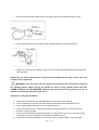
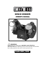
BENCH GRINDER OWNER’S MANUAL WARNING: Read carefully and understand all ASSEMBLY AND OPERATION INSTRUCTIONS before operating. Failure to follow the safety rules and other basic safety precautions may result in serious personal injury. Item#s 22481, 22483 Thank you very much for choosing a Wel-Bilt™ product! For future reference, please complete the owner’s record below: Model: _______________ Purchase Date: _______________ Save the receipt, warranty and these instructions. It is important that you read the entire manual to become familiar with this product before you begin using it. This machine is designed for certain applications only. The distributor cannot be responsible for issues arising from modification. We strongly recommend this machine not be modified and/or used for any application other than that for which it was designed. If you have any questions relative to a particular application, DO NOT use the machine until you have first contacted the distributor to determine if it can or should be performed on the product. For technical questions please call 1-800-222-5381. INTENDED USE: This Wel-Bilt 8in. Bench Grinder is ideal for use in sharpening chisels, axes and other wood-cutting tools. It is also useful for repairing tips on screwdrivers and drill bits or for removing excess metal burrs from pieces of cut metal. SPECIFICATIONS: 6in. (Item# 22481) 8in. (Item# 22483) • Rated Voltage: • Rated Input Power: • Delivers: • Wheel Size: • Wheel Grit: • Weight: 120 Volts, 60Hz 1/2 HP, 2.8 Amps 3450 RPM 6 x 3/4in. with 1/2in. arbor 36 and 60 22 lbs. 120 Volts, 60Hz 3/4 HP, 4.8 Amps 3450 RPM 8 x 1in. with 5/8in. arbor 36 and 60 35 lbs. GENERAL SAFETY RULES WARNING: Read and understand all instructions. Failure to follow all instructions listed below may result in serious injury. CAUTION: Do not allow persons to operate or assemble this Bench Grinder until they have read this manual and have developed a thorough understanding of how the Bench Grinder works. WARNING: The warnings, cautions, and instructions discussed in this instruction manual cannot cover all possible conditions or situations that could occur. It must be understood by the operator that common sense and caution are factors which cannot be built into this product, but must be supplied by the operator. SAVE THESE INSTRUCTIONS Page 2 of 14 IMPORTANT SAFETY CONSIDERATIONS WORK AREA Keep work area clean, free of clutter and well lit. Cluttered and dark work areas can cause accidents. Do not use your tool where there is a risk of causing a fire or an explosion; e.g. in the presence of flammable liquids, gasses, or dust. Power tools create sparks, which may ignite the dust or fumes. Keep children and bystanders away while operating a power tool. Distractions can cause you to lose control, so visitors should remain at a safe distance from the work area. Be aware of all power lines, electrical circuits, water pipes and other mechanical hazards in your work area, particularly those hazards below the work surface hidden from the operator’s view that may be unintentionally contacted and may cause personal harm or property damage. Be alert of your surroundings. Using power tools in confined work areas may put you dangerously close to cutting tools and rotating parts. ELECTRICAL SAFETY WARNING: Always check to ensure the power supply corresponds to the voltage on the rating plate. Do not abuse the cord. Never carry a portable tool by its power cord, or yank tool or extension cords from the receptacle. Keep power and extension cords away from heat, oil, sharp edges or moving parts. Replace damaged cords immediately. Damaged cords may cause a fire and increase the risk of electric shock. Grounded tools must be plugged into an outlet properly installed and grounded in accordance with all codes and ordinances. Never remove the grounding prong or modify the plug in any way. Do not use any adapter plugs. Check with a qualified electrician if you are in doubt as to whether the outlet is properly grounded. Double insulated tools are equipped with a polarized plug (one blade is wider than the other). This plug will fit in a polarized outlet only one way. If the plug does not fit fully in the outlet, reverse the plug. If it still doesn’t fit, contact a qualified electrician to install a polarized outlet. Do not change the plug in any way. Avoid body contact with grounded surfaces such as pipes, radiators, ranges, and refrigerators. There is an increased risk of electric shock if your body is grounded. When operating a power tool outside, use an outdoor extension cord marked “W-A” or “W.” These cords are rated for outdoor use and reduce the risk of electric shock. Extension Cord Use: Use only ‘Listed’ extension cords. If used outdoors, they must be marked “For Outdoor Use.” Those cords having 3-prong grounding type plugs and mating receptacles are to be used with grounded tools. Replace damaged or worn cords immediately. Check the nameplate rating of your tool. Use of improper size or gauge of extension cord may cause unsafe or inefficient operation of your tool. Be sure your extension cord is rated to allow sufficient current flow to the motor. For the proper wire gauge for your tool, see chart. Page 3 of 14 CHART FOR MINIMUM WIRE SIZE OF EXTENSION CORD: Nameplate AMPS CORD LENGTH 25ft. 50ft. 100ft. 150ft. 0-6 18 AWG 16 AWG 16 AWG 14 AWG 6-10 18 AWG 16 AWG 14 AWG 12 AWG 10-12 16 AWG 16 AWG 14 AWG 12 AWG 12-16 14 AWG 12 AWG (NOT RECOMMENDED) If in doubt, use larger cord. Be sure to check voltage requirements of the tool to your incoming power source. Do not expose power tools to rain or wet conditions. Water entering a power tool will increase the risk of electric shock. Do not let your fingers touch the terminals of plug when installing to or removing from the outlet. Ground fault circuit interrupters. If work area is not equipped with a permanently installed Ground Fault Circuit Interrupter outlet (GFCI), use a plug-in GFCI between power tool or extension cord and power receptacle. PERSONAL SAFETY Stay alert, watch what you are doing and use common sense when operating a power tool. Do not use a power tool while you are tired or under the influence of drugs, alcohol or medication. A moment of inattention while operating power tools may result in serious personal injury. Dress properly. Do not wear loose clothing, dangling objects, or jewelry. Keep your hair, clothing and gloves away from moving parts. Loose clothes, jewelry or long hair can be caught in moving parts. Air vents often cover moving parts and should be avoided. Use safety apparel and equipment. Use safety goggles or safety glasses with side shields which comply with current national standards, or when needed, a face shield. Use as dust mask in dusty work conditions. This applies to all persons in the work area. Also use non-skid safety shoes, hardhat, gloves, dust collection systems, and hearing protection when appropriate. Do not overreach. Keep proper footing and balance at all times. Remove adjusting keys or wrenches before connecting to the power supply or turning on the tool. A wrench or key that is left attached to a rotating part of the tool may result in personal injury. BENCH GRINDER USE AND CARE Check for misalignment or binding of moving parts, breakage of parts, and any other condition that may affect the tool’s operation. If damaged, have the tool serviced before using. Many accidents are caused by poorly maintained tools. Do not force the tool. Use the correct tool for your application. The correct tool will do the job better and safer at the rate for which it is designed. Do not use tool if switch does not turn it on or off. Any tool that cannot be controlled with the switch is dangerous and must be repaired. Page 4 of 14 Disconnect the plug from the power source before making any adjustments, changing accessories, or storing the tool. Such preventive safety measures reduce the risk of starting the tool accidentally. Use clamps or other practical way to secure and support the workpiece to a stable platform. Holding the work by hand or against your body is unstable and may lead to loss of control. Store idle tools out of reach of children and other untrained persons. Tools are dangerous in the hands of untrained users. Maintain tools with care. Keep cutting tools sharp and clean. Properly maintained tools, with sharp cutting edges are less likely to bind and are easier to control. Use only accessories that are recommended by the manufacturer for your model. Accessories that may be suitable for one tool may create a risk of injury when used on another tool. Never leave tool running unattended. Examine wheels for damage before operating, and replace if any damage is found. Do not overtighten wheel nuts. Use only wheel flanges furnished with bench grinder. Use of other flanges may cause damage or breakage to the wheel and result in injury to the operator. Do not force work against the wheel. Excessive pressure may cause damage or breakage of the wheel, resulting in injury to the operator or bystanders. Always use guards and eye shields. Use wheel suitable for speed of bench grinder. Do not operate bench grinder when flammable fumes are present. Sparks from the wheel or motor brush could ignite fumes. Tighten grinding wheel lock nuts, securing bolts and all clamps and guards. During each start-up, stand to one side of the grinder and switch it ‘On’. Let the grinder operate at full speed for approximately one minute so that any undetected flaws or cracks will become apparent. Always use proper guard with grinding wheel. A guard protects operator from broken wheel fragments. Keep hands clear of grinding wheels. Never reach behind or beneath the grinding wheels. Unplug from power supply before adjusting or servicing. The grinding wheels continue to rotate after the tool is switched off. Always allow wheels to stop before adjusting or servicing. When fitting a new grinding wheel, always check that the stated maximum RPM meets or exceeds that stated on the grinder. Also check the new wheel for damage, such as flaws or cracks. If the wheel appears satisfactory, fit it to the grinder. When a new grinding wheel has been fitted, stand to one side of the grinder and switch it ‘On’. Let the grinder operate at full speed for approximately one minute so that any undetected flaws or cracks will become apparent. DO NOT attempt to cut anything with the grinding wheel. When servicing a tool, use only identical replacement parts. Follow instructions in the maintenance section of this manual. Use of unauthorized parts or failure to follow maintenance instructions may create a risk of electric shock or injury. WARNING! Replace cracked grinding wheels immediately. Page 5 of 14 Do not overtighten spindle nuts. Adjust tool rests whenever necessary to maintain a distance of 1/8in. from the grinding wheel. ASSEMBLY: Mounting the Grinder to the Workbench Before attempting to use this grinder, it must be properly mounted to a workbench or grinding stand. WARNING! Bench grinders vibrate. Grinder movement during high-speed rotation may cause injury or damage to the workpiece or operator. Mount the grinder securely to a sturdy workbench or grinding stand. 1. Position the grinder on the workbench. 2. Mark the workbench through the two mounting holes located in the grinder base. 3. Drill holes in the workbench at the marks. 4. Using two long bolts, washers, lock-washers and nuts, as shown (not supplied), secure the grinder to the workbench. Eye Shield Installation Eye shields must be installed before operating the bench grinder. Page 6 of 14 1. Mount the left and right shield rods to the inside of the wheel guards using hex bolts. 2. Once shield rods are firmly in place, slide the shield bracket onto the shield rod. 3. Tighten the carriage bolt, leaving it loose enough to allow the safety shield to be raised and lowered easily. NOTE: The eye shield should move freely when being adjusted, but stay in place when the locking knob is tightened. WARNING! Turn the power off and remove the plug from the outlet before changing the grinding wheels. When turning the grinder on with a newly installed wheel, DO NOT STAND IN FRONT OF THE GRINDER. Stand to the side and allow the grinder to run for at least one minute before proceeding to use it. Installing or Changing the Wheel 1. Loosen the tool rest hex nuts and slide the tool rest away from the wheel. 2. Use a screwdriver to remove the wheel-cover screws and remove the wheel cover. 3. Fit an appropriately sized wrench on the spindle hex nut. 4. Loosen the wheel nut in a clockwise direction for the left side and a counter-clockwise direction for the right side. 5. Remove the outer flange and grinding wheel. To remove the hex nut, turn the wrench and nut until the wrench is resting on the workbench behind the tool. 6. Inspect the new wheel carefully to ensure there are no cracks, chips or other damage. Page 7 of 14 7. Wipe the flange surfaces clean, and install the new wheel, flange and the spindle hex nut. 8. To install a new grinding wheel, reverse the above procedure. 9. Be sure the grinding wheel and outer flange are properly seated on the spindle shaft. 10. Replace the wheel cover and reposition the tool rest. 11. The tool rest, spark deflector and eye shields will need to be readjusted after installation of the wheel is complete. 12. When turning the grinder on with a newly installed wheel, DO NOT STAND IN FRONT OF THE GRINDER. Stand to the side and allow the grinder to run for at least one minute before proceeding to use it. IMPORTANT! Do not overtighten the spindle hex nut, because this may cause the wheel to crack. CAUTION! DO NOT INSTALL OR USE A DAMAGED GRINDING WHEEL. The force of rotation may cause a damaged wheel to fly apart, and could injure operators or bystanders. Tool Rest Adjustments and Installation Mount the tool rests to the work rest bracket using the two hex screws and washers. Before tightening the bolts, adjust the gap between the grinding wheel and the work rest to a maximum of 1/8in. Tighten securely. Adjustments To prevent the workpiece from being pulled and caught between the tool rest and the wheel, readjust the tool rest position whenever necessary to maintain the 1/8in. distance. Page 8 of 14 1. Loosen, but do not remove, the two hex nuts holding the tool rest arm. 2. Slide the tool rest in or out to achieve a 1/8in. distance from the grinding wheel surface. 3. Re-tighten the two hex nuts. OPERATION: ON/OFF The rocker ON/OFF power switch is located on the front of the grinder. 1. Press the side marked ON to turn the grinder on. 2. Press the side marked OFF to turn the grinder off. Grinding Adjust the tool rest to accommodate large or unusually shaped workpieces. Always keep the workpiece moving across the face of the grinding wheel. Grinding continuously on the same spot on the wheel will cause grooves to be worn into the wheel. The wheel may crack or become damaged more easily, and grinding of other objects will be difficult. If the workpiece becomes hot, dip it into water to cool it. Always grind on the face of the wheel (around the diameter), NEVER on the sides. Side pressure on grinding wheels can cause cracking and damage. If the face of the grinding wheel is worn unevenly, becomes grooved, or is no longer smooth and flat, the wheel should be reshaped with a dressing tool (not supplied). If the diameter of the grinding wheel is no longer round, the wheel should be reshaped with a dressing tool or replaced. If the surface of the wheel becomes loaded and dull with workpiece material, the wheel should be cleaned with a dressing tool. After reshaping, always readjust the tool rests and spark arrestors. MAINTENANCE Maintenance Required Frequency 1. Check power cord Before each use. 2. Check wheels for cracks Before each use. 3. Check moving parts for alignment and binding issues Before each use. 4. Dress Grinding Wheels As needed 5. Replace Grinding Wheels (see manual section for specifics) As needed. 6. Clean and vacuum dust from the motor housing and other grinder parts As needed. 7. Replace work-light bulb As needed Tool service must be performed only by qualified repair personnel. Service or maintenance performed by unqualified personnel could result in a risk of injury. COOLANT TRAY When grinding, metal objects become heated quickly. It is important to keep moving the object back and forth across the face of the grinding wheel and to cool the object frequently using the coolant tray. Page 9 of 14 coolant tray WORKLIGHT BULB REPLACEMENT When the light bulb is worn out and will no longer work, unfasten the screws that hold the lamp cover, and then gently remove the bulb from the holder by pushing ‘in’ and turning counterclockwise. Contact distributor for replacement bulbs. To replace, gently push the light bulb into the socket and turn clockwise, and then reattach the lamp cover by reversing the instructions provided above. TROUBLESHOOTING Service on this Bench Grinder should only be performed by an authorized, qualified technician. SYMPTOM PROBABLE CAUSE Motor will not start. 1. Low Voltage. 2. Open circuit in motor or loose connections. 3. Blown fuse or breaker. Motor will not start – fuses or circuit breakers tripping or blowing. 1. Short circuit in line, cord or plug. 2. Short circuit in motor or loose connections. 3. Incorrect fuses or circuit breakers in power line. Motor overheats. 4. Motor overloaded. 5. Extension cord too long and of insufficient gauge (weight). Motor stalls (resulting in blown fuses or tripped circuit). 1. Short circuit in motor or loose connections. 2. Low voltage. 3. Incorrect fuses or circuit breakers in power line. 4. Motor overload. Page 10of 14 CORRECTIVE ACTION 1. Check power source for proper voltage. 2. Inspect all lead connection on motor for loose or open connections. (Send for Servicing.) 3. Short circuit. (Send for Servicing.) 4. Improper match between tool and circuit, fuse or breaker. 1. Inspect cord or plug for damaged insulation and shorted wires. 2. Inspect all connections on motor for loose or shorted terminals and/or worn insulation. 3. Install correct fuses or circuit breakers or switch tool to an appropriately sized circuit. 4. Reduce load on motor. 5. Utilize an extension cord of appropriate gauge and length or plug tool directly into outlet. 1. Inspect connections on motor for loose or shorted terminals or worn insulation. (Send for Servicing.) 2. Correct low voltage conditions (for example: improper extension cord length and/or gauge). 3. Install correct fuses or circuit breakers or plug tool into an appropriate circuit, matched to an appropriate fuse or breaker. 4. Reduce the load on the motor. Machine operating. slows when 1. Feed rate too great. Wavy condition on surface of workpiece. 1. Machine vibrating. 2. Workpiece not being held firmly. 3. Wheel face uneven. 4. Wheel is too hard. Lines on workpiece. 1. Impurity on surface of wheel. 2. Workpiece not being held tightly. surface of 1. Reduce the rate at which the workpiece is fed into the working area of the tool (grinding wheel). 1. Ensure machine is securely mounted on a solid surface. 2. Use a holding device to firmly retain the workpiece. 3. Dress the grinding wheel. 4. Use softer wheel, or reduce the feed rate. 1. Dress the grinding wheel. 2. Use a holding device to more firmly retain the workpiece. Burning spots or cracks in the workpiece. 3. Improper type of grinding wheel. 4. Improper feed rate. 5. Coolant required. 3. Try wheels with softer bond or coarser grit. 4. Slow down the rate at which the workpiece is fed into the wheel. 5. Add coolant. Wheel dulls quickly, grit falls off. 6. 7. 8. 9. 10. Feed rate is too aggressive. Wheel is soft. Wheel diameter too small. Bad wheel dressing. Defective wheel bonding. Wheel clogs and workpiece shows burn marks. 11. 12. 13. 14. Wheel is too hard. Feed rate is too slow. Bad wheel dressing. Coolant required. 6. Decrease feed rate of workpiece into grinding wheel. 7. Select a grinding wheel with a harder bond of material. 8. Replace wheel. 9. Dress the wheel. 10. DO NOT USE – return wheel to point of purchase. 11. Select a grinding wheel with a softer bond of material. 12. Increase the feed rate of the workpiece into the grinding wheel. 13. Dress the wheel. 14. Add coolant. Page 11of 14 DIAGRAM & PARTS LIST Page 12of 14 ITEM DESCRIPTIONS QTY. ITEM DESCRIPTIONS QTY. 1 Philips Screw (Zinc-plated) 14 35 Cord Clip 3 2 Philips Screw (Black) 6 36 Cord & Plug 1 3 Left Wheel Guard Cover 1 37 Cord Clip Fixed Plate 1 4 Hex Nut Type "I" (Zinc-plated) 1 38 Spring Washer (Black) 2 5 Wheel Flange 4 39 Hexagon Nut 4 6 36#Wheel,P200x25x15.88 1 40 Switch Plate 1 7 Philips Screw (Zinc-plated) 6 41 Switch 1 8 Spring Washer (Black) 16 42 Flat Washer (Zinc-plated) 2 9 Left Wheel Guard 1 43 Toothed Lock Washer (Black) 1 10 Little Philips Screw (Black) 8 44 Motor Housing 1 11 Cord Press Plate 2 45 Wire Bushing 1 12 Lamp Base 2 46 Stator 1 13 Hex Nut 2 47 Rotor 1 14 Philips Screw (Black) 4 48 Flat Washer (Zinc-plated) 4 15 Cord Press Base Plate 2 49 Philips Screw (Zinc-plated) 4 16 Philips Screw (Black) 4 50 Magnifier Mount Rod 1 17 Philips Screw (Black) 4 51 Magnifier Eyeshield Assy 1 18 Lamp Cover Assy 2 52 Right Sparkle Deflector 1 19 Lamp Holder 2 53 Right Work Rest 1 20 Hex Nut Type "I" (Black) 6 54 Right Wheel Guard 1 21 Left Spark Deflector 1 55 60#Wheel,P200x25x15.88 1 22 Plain Eyeshield Assy 1 56 Hex Nut Type "I" (Zinc-plated) 1 23 Eyeshield Mount Rod 1 57 Right Wheel Guard Cover 1 24 Flat Washer (Black) 2 58 Base 1 25 Spring Washer (Black) 2 59 Hex Nut Type "I" (Zinc-plated) 1 26 Hex Bolt (Black) 2 60 Capacitor 1 27 Eyeshield Lock Knob 2 61 Capacitor Support 1 28 Left Work Rest 1 62 Tool Storage Bottom Cover 1 29 Flat Washer (Black) 4 63 Tool Storage 1 30 Hex Bolt (Black) 4 64 Rubber Foot 4 31 Philips Screw (Zinc-plated) 4 65 Big Flat Washer (Zinc-plated) 4 32 End Caps 2 66 Lamp 2 33 Wave Spring Washer 1 67 Philips Screw (Black) 4 34 Ball Bearing 2 68 Hex Nut Type "I" (Zinc-plated) 4 For replacement parts and technical questions, please call 1-800-222-5381. Page 13of 14 WARNING Some dust created by power sanding, sawing, grinding, drilling, and other construction activities contains chemicals known to the State of California to cause cancer, birth defects or other reproductive harm. Some examples of these chemicals are: • lead from lead-based paints, • crystalline silica from bricks and cement and other masonry products, and • arsenic and chromium from chemically-treated lumber. Your risk from these exposures varies, depending on how often you do this type of work. To reduce your exposure to these chemicals: work in a well ventilated area, and work with approved safety equipment, such as those dust masks that are specially designed to filter out microscopic particles. Distributed by Northern Tool + Equipment Co., Inc. Burnsville, Minnesota 55306 NorthernTool.com Made in China Page 14of 14