1
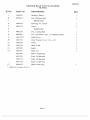
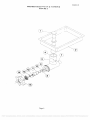
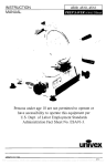
INSTRUCTION
MANUAL
MEAT GRINDER
Persons under age 18 are not permitted to operate or
have accessibility to operate this equipment per
U.S. Dept. of Labor Employment Standards
Administration Fact Sheet No. ESA91-3.
univex
MG8912/0303
ED5
PDF compression, OCR, web optimization using a watermarked evaluation copy of CVISION PDFCompressor
MG8912
INSTRUCTION MANUAL
MODEL MG8912 MEAT GRINDER
The UNI VEX Model MG8912 Meat Grinder is a portable electric power driven machine
designed to process 8 to 12 lb. of meat per minute. It consists of a I HP drive assembly with a No.
12 drive hub operating at 250 RPM; a grinder head assembly with interchangeable plates to vary
the texture of the processed meat; an 8 qt. feed pan to hold the meat that is to be processed; and a
plastic stomper to insert the meat into the grinder.
INSPECTION
The assemblies are inspected and tested at the factory; however, the user should examine the
grinder head assembly (Fig. 2) and compare the parts ordered and received with the parts list. The
drive assembly (Fig. 1) is complete and requires only to be externally inspected and electrically
checked prior to use. The electrical data listed on the nameplate of the drive assembly should be
the same as the user's electrical supply. Any damage should be reported to the carrier immediately,
and any shortage or deviation of parts to UNI VEX Corporation.
SAFETY
The user should read and understand these instructions prior to operating the machine. New
operator& should be properly trained in safety precautions to be observed for the proper use and
servicing ofthis machine.
Switch the power "OFF" and disconnect the electrical supply prior to mounting or
dismounting the grinder head, cleaning, or servicing the machine.
Switch the power 'OFF' prior to connecting the electrical supply or resetting the circuit
breaker. To prevent unauthorized operation, the power switch can be lock in the OFF" position by
removing the switch key. A manual resettable overload circuit breaker is provided on the back of
the machine, In case this circuit breaker is actuated, switch the power "OFF', disconnect the
electrical supply, determine and correct the fault prior to resetting the breaker.
Assure that the meat chopper is properly assembled and installed with the thumb screw
tightenedbefore connecting the electrìcal supply.
The knife is sharp. Use extreme care when handling or cleaning.
Do not put your fingers in the throat of the grinder when the electrical supply is connected.
Use the plastic stomper for inserting meat into the grinder. Do not put fingers or objects into plate
holes.
Wipe down the exterior of the drive assembly only. Never hose down or immerse the drive
assembly in water.
Do not attempt to service the drive assembly yourself. Refer to the list of UNI VEX
approved service representatives for adjustment or repair of your UNI VEX equipment.
ASSEMBLY
Attach the Pan Support (Fig. 1 Item 7) to the Housing Cover (Item 3) using screws provided.
The PTO adapter (Fig. 1 Item 24,) should remain on the PTO drive shaft when the grinder
head is removed. The Grinder Head Housing Assembly (Fig. 2 Item 4 through 8,) should be
maintained as an integral unit. No additional disassembly of these components should occur.
Likewise, the Worm Assembly (Fig. 2 Items 9 through 12,) should be maintained as an integral
unit. These assemblies and the other components of the Grinder Head Assembly should be washed
with awarmwater and soap solution and driedpriorto use. Inspectthe Knife (Item 13) for
sharpness and handle carefully.
Page 1
PDF compression, OCR, web optimization using a watermarked evaluation copy of CVISION PDFCompressor
MG8912
Insert the housing of the Grinder Head Assembly into the PTO housing of the Drive
Assembly. Tighten the thumb screw and assure that the engagement is proper and secure. Lightly
coat the Drive Shaft (Item 9) and Fiber Washer (Item 10) of the Worm Assembly with Drive Shaft
Lubricant (Item 16). Insert the Worm Assembly into the Housing, assuring that it is engaged in the
PTO adapter.
The Knife and Grinder Plate (Items 13 & 14) should be coated with the lubricant provided
or beef tallow prior to assembly. Place the Knife, SHARP EDGES OUT, on the square extension
of the Worm Assembly. Place the Grinder Plate on the worm assembly extension so that the notch
in the plate engages the pin in the grinder housing. Screw the Hand wheel Ring (Item 15) on the
housing assembly using only minimum force. The ring controls the pressure between the plate and
the knife. The knife is easily damaged by dry running or excessive force on the Hand wheel Ring.
Mount the Feed Pan on the top of the Drive Assembly so that its outlet spout engages the
inlet throat of the Grinder Assembly Housing.
PROCESSING
Locate the equipment for the convenience of the operator, allowing free access to the power
switch and sufficient clearance for safety and care of operation. Slice the meat into strips which
will easily fit into the outlet of the Feed Pan. Place a suitable container at the discharge of the
Grinder Head. Place the meat in the Feed Pan and start grinder. Hand feed the meat into the outlet
of the pan using the stomper to feed the meat into the grinding worm. Do not use the stomper to
force feed the grinder at an increased rate. Best results are obtained when the meat is fed only as
fast as the grinder processes it. Switch the power 'OFF when processing is interrupted. When the
processing has been compled, switch the power "OFF" and disconnect the power supply cord.
Dismount the Grinder Head from the Drive. Disassemble, wash, and dry the components of the
Grinder Head. Store the components in a refrigerator for added sanitation.
Page 2
PDF compression, OCR, web optimization using a watermarked evaluation copy of CVISION PDFCompressor
MG8912
MG8912 MEAT GRINDER ASSEMBLY
FIGURE 1
ITEM NO. PART NO.
DESCRIPTION
2
3
4
5
6
7
8
9
10
11
12
13
14
15
16
17
18
19
20
21
22
23
24
25
26
27
28
29
30
31
32
33
34
35
36
37
38
39
40
8700001
8700014
8700002
4400141
1200075
1200442
8700012
8700009
1030019
4400072
8800010
4400230
1200117
1200119
8700025
8700010
1200025H
4400005
8700035
8700036
8700019
4400045
8800012
1200412
1200415
8700024
4400410
7510094
1200012
4400414
8700026
4400415
1200411
1200413
4400416
8700032
4400398
1012042
8800100
8800100-2
41
42
1030307E
43
47
48
4400417
1200076
8700022
4400351
1200060
4400065
40
49
50
8800100-1
4400239
4400227
44
45
46
Housing
Foam, Rubber Strip
Cover, Housing
Nut, Kep 1/4-20
Washer, Steel Flat 1/4
Screw, Truss HD 10-32 x 1/2
Bracket, Pan support
Sleeve, Pan Support
Reserved
Ball Bearing 6204ZZ
Set Screw 5/16-18 x 3/8
Shaft, P T O
Key 3/16 Square
Retaining Ring mt.
Retaining Ring Ext.
Pulley, Driven
Belt, Drive 300J10
Screw, Hex HD 1/4-20 x 3/4
Lockwasher 1/4
Switch, With Key
Key, Switch (Key Only)
Knob Assembly, P T O
Housing, P T O
Adaptor, P T O
Set Screw 1/4-20 x 1/4
Bolt, 10-32 x 1/4
Pulley, Drive
Nut 8M x 1.25
Feet
Screw, Phil HD 10-3 2 x 1/2
Washer, Flat 1/4
Spring, Compression
Sleeve (Long)
Screw, Hex BD 1/2-20 x 2
Screw, Hex HD 1/4-20 x 1 1/2
Sleeve (Short)
Spacer, Isolator
Cable Tie
Strain Relief
Cord, Electric 115V
Cord, Electric 220V
Reserved
Motor, I HP. 115V, 60HZ
Motor, i HP, 220V, 60HZ
Sleeve, Spring
Washer no. 10
Label, Attention (Not Shown)
Label, Caution (Not Shown)
Nut, Hex 10-32
Lockwasher, #10
FOR CSA ONLY)
Cord, Electric 115V
Circuit Breaker
Label, Reset (Not Shown)
OTY.
2
4
7
4
2
2
2
2
3
3
1
1
i
2
4
4
6
4
2
2
2
2
2
4
3
2
2
5
4
Page 3
PDF compression, OCR, web optimization using a watermarked evaluation copy of CVISION PDFCompressor
MG89 12
MG8912 MEAT GRINDER ASSEMBLY
FIGURE 1
Page 4
PDF compression, OCR, web optimization using a watermarked evaluation copy of CVISION PDFCompressor
MG8912
GRINDER HEAD W/PAN & STOMPER
FIGURE 2
ILLUS.
PART NO.
DESCRIPTION
1
1000505
Stomper, Plastic
2
870001 1
Pan, Stainless Steel
4
100065 1
Housing, No. 12 hub
5
4400351
Label,
7
4400275
Pin, Locating Hub
8
4400050
Pin, Lock Plate 5/32 x 1 1/2 Stainless Steel
9
1000519 *
Shaft, Drive
10
1000516
Fiber Washer 3/4 x 1 5/16 x 1/8
11
1000653
Worm
12
1000518
Shaft, Front
13
1000506
Knife
14
1000509
Plate 3/16
1000508
Plate 1/8 Optional
1000510
Plate 1/4 Optional
1000511
Plate 3/8 Optional
1000512
Plate 1/2 Optional
1000652
Hand wheel Ring
RESERVED
3
6
15
*
QTY
RESERVED
Illus No. 9 is part ofNo 11
Page 5
PDF compression, OCR, web optimization using a watermarked evaluation copy of CVISION PDFCompressor
MG912
GRINDER HEAD W/PAN & STOMPER
FIGURE 2
Page 6
PDF compression, OCR, web optimization using a watermarked evaluation copy of CVISION PDFCompressor