1
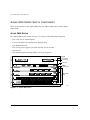
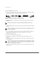
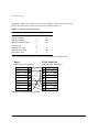
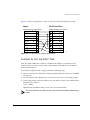
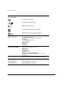
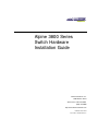
Alpine 3800 Series
Switch Hardware
Installation Guide
Extreme Networks, Inc.
3585 Monroe Street
Santa Clara, California 95051
(888) 257-3000
http://www.extremenetworks.com
Published: March 2000
Part number: 100054-00 Rev. A
©2000 Extreme Networks, Inc. All rights reserved. Extreme Networks and BlackDiamond are registered
trademarks of Extreme Networks, Inc. in the United States and certain other jurisdictions.
ExtremeWare, ExtremeWare Vista, ExtremeWorks, ExtremeAssist, ExtremeAssist1, ExtremeAssist2,
PartnerAssist, Extreme Standby Router Protocol, ESRP, SmartTraps, Alpine, Summit, Summit1,
Summit4, Summit4/FX, Summit7i, Summit24, Summit48, Summit Virtual Chassis, SummitLink,
SummitGbX, SummitRPS and the Extreme Networks logo are trademarks of Extreme Networks, Inc.,
which may be registered or pending registration in certain jurisdictions. The Extreme Turbodrive logo
is a service mark of Extreme Networks, which may be registered or pending registration in certain
jurisdictions. All other registered trademarks, trademarks and service marks are property of their
respective owners. Specifications are subject to change without notice.
ii
Contents
PREFACE
Introduction xi
Conventions xii
Related Publications
1
xiii
ALPINE 3800 SERIES SWITCH OVERVIEW
Summary of Features 1-1
Port Connections 1-3
Media Types and Distances 1-4
Full-Duplex 1-5
Alpine 3800 Series Switch Components 1-6
Alpine 3804 Switch 1-6
Alpine 3808 Switch 1-7
Alpine 3800 Series Switch Power Supply 1-8
Power Supply LEDs 1-8
Switch Management Module 1-9
SMMi Memory 1-10
SMMi LEDs 1-10
Alpine 3800 Series Switch Fan Tray 1-11
I/O Module Cards 1-11
GM-4Ti Module 1-11
GM-4Xi Module 1-13
GM-4Si Module 1-14
FM-32Ti Module 1-15
FM-24Fi Module 1-16
iii
I/O Module LEDs 1-16
Alpine 3804 Switch Rear View 1-17
Alpine 3808 Switch Rear View 1-18
2
INSTALLATION
AND
SETUP
Following Safety Information 2-1
Determining the Switch Location 2-2
Installing the Alpine 3800 series switch 2-2
Installing the Alpine 3800 series switch components
Installing the Power Supplies 2-6
Installing Module Cards 2-7
Powering On the System 2-9
Checking the Installation 2-9
Connecting Equipment to the Console Port 2-9
Logging In for the First Time 2-11
3
SERVICE
AND
2-6
MAINTENANCE
Following Safety Information 3-1
Removing and Replacing a Module Card 3-2
Removing and Replacing a Power Supply 3-3
Removing and Replacing an Alpine 3804 Power Supply 3-3
Removing and Replacing an Alpine 3808 Power Supply 3-5
Removing and Replacing the Fan Tray 3-7
Removing and Replacing the Alpine 3804 Fan Tray 3-7
Removing and Replacing the Alpine 3808 Fan Tray 3-9
Adding and Removing SODIMMs 3-11
Adding and Removing GBICs 3-12
A
SAFETY INFORMATION
Important Safety Information
Power A-1
Power Cord A-2
Connections A-3
Lithium Battery A-3
iv
A-1
B
TECHNICAL SPECIFICATIONS
INDEX
v
vi
Figures
1-1
1-2
1-3
1-4
1-5
1-6
1-7
1-8
1-9
1-10
1-11
2-1
2-2
2-3
2-4
2-5
2-6
2-7
3-1
3-2
3-3
3-4
3-5
3-6
3-7
3-8
Alpine 3804 switch 1-6
Alpine 3808 Switch 1-7
Switch Management Module (SMMi) 1-9
SMMi SODIMM sockets 1-10
GM-4Ti module 1-12
GM-4Xi module 1-13
GM-4Si module 1-14
FM-32Ti module 1-15
FM-24Fi module 1-16
Alpine 3804 switch rear view 1-17
Alpine 3808 switch rear view 1-18
Rack-mount helper bracket 2-3
Alpine 3804 chassis mounted in rack 2-4
Alpine 3808 chassis mounted in rack 2-5
Power supply bays 2-6
SMMi with extended ejector/injector handles 2-8
Null-modem cable pinouts 2-10
PC-AT serial null-modem cable pinouts 2-11
Alpine 3804 power supply 3-4
Alpine 3808 power supply 3-5
Removing the Alpine 3804 fan tray 3-7
Alpine 3804 fan tray 3-8
Removing the fan tray 3-9
Alpine 3808 fan tray 3-10
Adding a SODIMM 3-11
GBIC connectors 3-12
vii
viii
Tables
1
2
1-1
1-2
1-3
1-4
1-5
1-6
2-1
Notice Icons xii
Text Conventions
xii
Media Types and Distances
1-4
1000BASE-LX70 Specifications
1-5
1000BASE-SX and 1000BASE-LX Specifications
Power Supply LEDs
1-8
SMMi LEDs
1-10
I/O Module LEDs
1-16
Console Connector Pinouts 2-10
1-5
ix
x
Preface
This Preface provides an overview of this guide, describes guide conventions, and lists
other publications that may be useful.
INTRODUCTION
This guide provides the required information to install the Alpine™ 3800 series switch.
This guide is intended for use by network administrators who are responsible for
installing and setting up network equipment. It assumes a basic working knowledge of:
• Local Area Networks (LANs)
• Ethernet concepts
• Ethernet switching and bridging concepts
• Routing concepts
• Simple Network Management Protocol (SNMP)
For information on configuring the Alpine 3800 series switch, refer to the ExtremeWare
Software User Guide.
If the information in the “Release Notes” shipped with your switch differs from the
information in this guide, follow the “Release Notes.”
ALPINE 3800 SERIES SWITCH HARDWARE INSTALLATION GUIDE
XI
PREFACE
CONVENTIONS
Table 1 and Table 2 list conventions used throughout this guide.
Table 1: Notice Icons
Icon
Notice Type
Alerts you to...
Note
Important features or instructions.
Caution
Risk of personal injury, system damage,
or loss of data.
Warning
Risk of severe personal injury.
Table 2: Text Conventions
Convention
Description
Screen displays
This typeface represents information as it appears on the screen,
or command syntax.
Screen displays bold
This typeface represents commands that you type.
The words “enter”
and “type”
When you see the word “enter” in this guide, you must type
something, and then press the Return or Enter key. Do not press
the Return or Enter key when an instruction simply says “type.”
[Key] names
Key names appear in text in one of two ways:
■
Referred to by their labels, such as “the Return key” or “the
Escape key”
■
Written with brackets, such as [Return] or [Esc]
If you must press two or more keys simultaneously, the key
names are linked with a plus sign (+). Example:
Press [Ctrl]+[Alt]+[Del].
Words in italicized type
XII
Italics emphasize a point or denote new terms at the place where
they are defined in the text.
ALPINE 3800 SERIES SWITCH HARDWARE INSTALLATION GUIDE
RELATED PUBLICATIONS
RELATED PUBLICATIONS
The Alpine documentation set includes the following:
• ExtremeWare Software User Guide
• ExtremeWare Quick Reference Guide
Documentation for Extreme Networks products is available on the World Wide Web at
the following location:
• http://www.extremenetworks.com/support/documentation.asp
ALPINE 3800 SERIES SWITCH HARDWARE INSTALLATION GUIDE
XIII
PREFACE
XIV
ALPINE 3800 SERIES SWITCH HARDWARE INSTALLATION GUIDE
1
Alpine 3800 Series Switch
Overview
The Alpine 3800 series switch is a chassis-based, Ethernet service provisioning switch
designed for edge and aggregation applications. The Alpine 3800 series switch is
flexible and scalable, making it easy for you to meet the changing requirements of your
network. The combination of BlackDiamond, Alpine, and Summit switches delivers a
consistent end-to-end network solution that provides a nonblocking architecture,
wire-speed switching, wire-speed IP routing, and policy-based Quality of Service (QoS).
This chapter describes the following:
• Alpine 3800 series switch features
• Network configurations using the Alpine 3800 series switch
• Alpine 3800 series switch components
SUMMARY
OF
FEATURES
The features of the Alpine 3800 series switch include the following:
• A 5-slot or 9-slot chassis that can be populated with up to 4 or 8 input/output (I/O)
modules and one Switch Management Module (SMMi)
• I/O modules are hot-swappable, and include Gigabit Ethernet or 10/100 Mbps
Ethernet ports
• Redundant, load-sharing, hot-swappable power supplies
• Field-replaceable, hot-swappable fan tray
Alpine 3800 Series Switch Hardware Installation Guide
1-1
ALPINE 3800 SERIES SWITCH OVERVIEW
• Up to 128 switched 10BASE-T/100BASE-TX Ethernet ports (model 3804), or up to
256 switched 10BASE-T/100BASE-TX Ethernet ports (model 3808)
• Up to 96 switched 100BASE-FX Fast Ethernet ports (model 3804), or up to 192
switched 100BASE-FX Fast Ethernet ports (model 3808)
• Up to 16 switched Gigabit Ethernet ports (model 3804), or up to 32 switched Gigabit
Ethernet ports (model 3808)
• Fully nonblocking operation
— All ports transmit and receive packets at wire speed
• Autonegotiation for half- or full-duplex operation on 10/100 Mbps ports
• Load-sharing on multiple ports
• Virtual local area networks (VLANs), including support for IEEE 802.1Q
• Spanning Tree Protocol (STP) (IEEE 802.1D) with multiple STP domains
• Policy-Based Quality of Service (QoS)
• Wire-speed Internet Protocol (IP) routing
• IP Multinetting
• Dynamic Host Configuration Protocol/Bootstrap Protocol (DHCP/BOOTP) Relay
• Routing Information Protocol (RIP) version 1 and RIP version 2
• Open Shortest Path First (OSPF) routing protocol
• IPX routing, including RIP and Service Advertisement Protocol (SAP)
• Wire-speed IP multicast routing support
• Internet Group Multicast Protocol (IGMP) and IGMP snooping
• Distance Vector Multicast Routing Protocol (DVMRP)
• IGMP snooping to control IP multicast traffic
• Console (RS-232) command-line interface (CLI) connection
• Telnet CLI connection
• ExtremeWare™ Vista™ Web-based management interface
• Simple Network Management Protocol (SNMP) support
• Dedicated 10BASE-T/100BASE-TX port for out-of-band management via CLI,
ExtremeWare Vista, and/or SNMP
1-2
Alpine 3800 Series Switch Hardware Installation Guide
SUMMARY
OF
FEATURES
PORT CONNECTIONS
Both Alpine 3800 series switches support the following I/O modules:
• GM-4Ti module
The GM-4Ti module has four Gigabit Ethernet ports, using standard RJ-45
connectors. The GM-4T module supports autonegotiation of
100BASE-TX/1000BASE-T.
• GM-4Xi module
The GM-4Xi module has four Gigabit Ethernet ports, using standard Gigabit
Interface Connectors (GBICs). The GM-4Xi module supports 1000BASE-SX,
1000BASE-LX, and 1000BASE-LX70 GBIC modules.
• GM-4Si module
The GM-4S imodule has four Gigabit Ethernet ports, using standard MT-RJ
connectors. The GM-4Si module supports 1000BASE-SX only.
• FM-32Ti module
The FM-32Ti module has 32 10/100 Mbps autonegotiating Ethernet ports, using
standard RJ-45 connectors. The FM-32Ti module supports 10BASE-T and
100BASE-TX.
• FM-24Fi module
The FM-24Fi module has 24 100 Mbps Ethernet ports, using standard MT-RJ
connectors. The FM-24Fi module supports 100BASE-FX in full-duplex mode only.
Caution: Modules that use SX, LX, LX70, and FX interfaces contain Class 1
laser devices. Invisible laser radiation can occur when open. Avoid direct eye
exposure to beam.
Alpine 3800 Series Switch Hardware Installation Guide
1-3
ALPINE 3800 SERIES SWITCH OVERVIEW
MEDIA TYPES
AND
DISTANCES
Table 1-1 describes the media types and distances for the different types of Alpine 3800
series switch ports.
Table 1-1: Media Types and Distances
Standard
Media Type
Mhz/Km
Rating
Maximum
Distance
1000BASE-SX
50/125 µm Multimode Fiber
400
500 Meters
50/125 µm Multimode Fiber
500
550 Meters
62.5/125 µm Multimode Fiber
160
220 Meters
62.5/125 µm Multimode Fiber
200
275 Meters
50/125 µm Multimode Fiber
400
550 Meters
50/125 µm Multimode Fiber
500
550 Meters
62.5/125 µm Multimode Fiber
500
550 Meters
1000BASE-LX
10u Single-mode Fiber
5,000 Meters
10u Single-mode Fiber*
10,000 Meters
1000BASE-LX70
10u Single-mode Fiber
70,000 Meters
100BASE-FX
50/125 µm Multimode Fiber
(full-duplex operation)
2000 Meters
62.5/125 µm Multimode Fiber
(full-duplex operation)
2000 Meters
1000BASE-T
Category 5 and higher UTP Cable
100 Meters
100BASE-TX
Category 5 and higher UTP Cable
100 Meters
10BASE-T
Category 3 and higher UTP Cable
100 Meters
*Extreme Networks proprietary. Connections between two Extreme Networks 1000BASE-LX interfaces can use a maximum
distance of 10,000 meters.
1-4
Alpine 3800 Series Switch Hardware Installation Guide
SUMMARY
OF
FEATURES
Table 1-2 describes the specifications for the 1000BASE-LX70 interface.
Table 1-2: 1000BASE-LX70 Specifications
Parameter
Minimum
Typical
Maximum
Optical Output Power
0dBm
3dBm
5dBm*
Center Wavelength
1540nm
1550nm
1560nm
Transceiver
Receiver
Optical Input Power Sensitivity
-20dBm
Optical Input Power Maximum
Operating Wavelength
-3dBm
1200nm
1560nm
*The transmitter output power level for the 1000BASE-LX70 is +5dBm. The maximum allowable receiver input power level is
-3dBm. Therefore, there is a minimum of 8dB loss required for the link to operate without errors. This minimum required loss
can be achieved using a fiber length of 32km (0.25dB/km provides 8dB loss), or by adding 10dB of fixed optical attenuator at
the receiver end.
Table 1-3 describes the specifications for the 1000BASE-SX and 1000BASE-LX interfaces.
Table 1-3: 1000BASE-SX and 1000BASE-LX Specifications
Parameter
Minimum
Maximum
SX
-9.5dBm
0dBm
LX
-11dBm
-3dBm
SX
-17dBm
0dBm
LX
-19dBm
-3dBm
Tranceiver
Receiver
FULL-DUPLEX
The Alpine 3800 series switch provides full-duplex support for all ports. Full-duplex
allows frames to be transmitted and received simultaneously and, in effect, doubles the
bandwidth available on a link. All ports on the Alpine 3800 series switch autonegotiate
for half- or full-duplex operation. Gigabit Ethernet and 100BASE-FX ports operate in
full-duplex mode, only.
Alpine 3800 Series Switch Hardware Installation Guide
1-5
ALPINE 3800 SERIES SWITCH OVERVIEW
ALPINE 3800 SERIES SWITCH COMPONENTS
There are two models in the Alpine 3800 series: the Alpine 3804 switch, and the Alpine
3808 switch.
ALPINE 3804 SWITCH
The Alpine 3804 switch, shown in Figure 1-1, consists of the following components:
• One 5-slot chassis with backplane
• Four I/O module slots, labeled Slot 1 through Slot 4
• One SMM module slot
• One or two power supplies (accessed from the rear of the unit)
• One fan tray
• One electromagnetic discharge (ESD) wrist strap receptacle
ESD
wrist strap
connector
Fan tray
SMM
module slot
1
2
3
4
1
2
3
4
I/O module
slots
1
2
3
4
5
6
7
8
9
10
11
12
13
14
15
16
17
18
19
20
21
22
23
1
4
5
8
9
12
13
16
17
20
21
24
25
28
29
32
24
38_3804
Figure 1-1: Alpine 3804 switch
1-6
Alpine 3800 Series Switch Hardware Installation Guide
ALPINE 3800 SERIES SWITCH COMPONENTS
ALPINE 3808 SWITCH
The Alpine 3808 switch, shown in Figure 1-2, consists of the following components:
• One 9-slot chassis with backplane
• Eight I/O module slots, labeled Slot 1 through Slot 8
• One SMM module slot
• Two power supply slots
• One fan tray
• One electromagnetic discharge (ESD) wrist strap receptacle
Blank for
second
power
supply
SERVICE
45012
WHEN INSTALLED IN 3808 THIS WAY UP
Hz
50
60
A
13
6
Hz
50
60
V
100-120
200-240
V
100-120
200-240
SLIDE TO REMOVE
Power
supply
ESD
wrist strap
connector
A
13
6
WHEN INSTALLED IN 3804 THIS WAY UP
DC OK
DC OK
Fan tray
SMM
module slot
1
2
3
4
1
2
3
4
1
2
3
4
1
2
3
4
I/O module
slots
1
2
3
4
5
6
7
8
9
10
11
12
13
14
15
16
17
18
19
20
21
22
23
24
1
2
3
4
5
6
7
8
9
10
11
12
13
14
15
16
17
18
19
20
21
22
23
24
1
4
5
8
9
12
13
16
17
20
21
24
25
28
29
32
1
4
5
8
9
12
13
16
17
20
21
24
25
28
29
32
38_3808
Figure 1-2: Alpine 3808 Switch
Alpine 3800 Series Switch Hardware Installation Guide
1-7
ALPINE 3800 SERIES SWITCH OVERVIEW
ALPINE 3800 SERIES SWITCH POWER SUPPLY
The Alpine 3800 series switch can have one or two AC or DC power supplies. The AC
power supplies auto-sense for 110V and 220V power. The DC power supplies require
-48 VDC input line voltage. When two power supplies are present, the power is
load-shared between the supplies for enhanced longevity. AC and DC power supplies
may be combined in the same chassis. Both AC and DC power supplies are
hot-swappable.
SNMP traps are sent for the following events:
• AC power failure
• Power supply failure
• Power supply is removed
POWER SUPPLY LEDS
Table 1-4 describes the light emitting diode (LED) behavior on the power supply.
Table 1-4: Power Supply LEDs
LED
Color
Indicates
D/C OK
Green
All DC outputs are operational
Off
One or more DC outputs have failed
1-8
Alpine 3800 Series Switch Hardware Installation Guide
ALPINE 3800 SERIES SWITCH COMPONENTS
SWITCH MANAGEMENT MODULE
The Switch Management Module (SMMi) is responsible for upper-layer protocol
processing and switch management functions. The SMMi can store two ExtremeWare
software images (version 6.0 or greater) and two switch configurations.
Figure 1-3 shows the SMMi.
Module status
LEDs
Console
port
Modem
port
Module
reset
Management
port
PCMCIA slot
38_SMMi
Figure 1-3: Switch Management Module (SMMi)
The SMMi has the following out-of-band management ports:
• Console port (used to connect a terminal and perform local management)
• 10/100BASE-TX Ethernet port
• Modem port (used to connect a modem for remote access to the CLI)
• PCMCIA slot (not used for normal operation)
Alpine 3800 Series Switch Hardware Installation Guide
1-9
ALPINE 3800 SERIES SWITCH OVERVIEW
SMMI MEMORY
The SMMi has two 144-pin SODIMM sockets, and ships with two 128MB SODRAM
modules installed, as shown in Figure 1-4.
Only SODIMMs supplied by Extreme Networks are supported in the SMMi.
38_SODMs
Figure 1-4: SMMi SODIMM sockets
For information on adding or removing SODIMMs, refer to Chapter 3.
SMMI LEDS
Table 1-5 describes the LED behavior on the SMMi.
Table 1-5: SMMi LEDs
LED
Color
Indicates
DIAG
Green (blinking)
Power-on Self Test (POST) is running
Off
Normal operation
Green (blinking)
Normal Operation
Yellow (blinking)
Critical error, fan failure or over temperature
Off
Unit powered down
PSUA
Green
PSU is OK
PSUB
Amber
DC output failure
Off
PSU not present or not powered
STATUS
1-10
Alpine 3800 Series Switch Hardware Installation Guide
ALPINE 3800 SERIES SWITCH COMPONENTS
ALPINE 3800 SERIES SWITCH FAN TRAY
The fan tray for the Alpine 3804 contains 3 fans and the fan tray for the Alpine 3808
contains 5 fans. Fan trays for each model are accessed from the front of the chassis. The
fan status is monitored by the software for fan failure conditions. All fan failures and
over-temperature events trigger management alerts (for example, SNMP traps and
SYSLOG messages). For more information on switch monitoring, refer to the
ExtremeWare Software User Guide.
I/O MODULE CARDS
The Alpine 3800 series switch has five I/O modules, as follows:
• GM-4Ti module
• GM-4Xi module
• GM-4Si module
• FM-32Ti module
• FM-24Fi module
I/O modules can be inserted or removed at any time, without causing disruption of
network services. No configuration information is stored on the I/O modules; all
configuration information is stored on the SMMi.
When the Alpine 3800 series switch is powered on, ExtremeWare generates a default
configuration for any slots that are occupied with I/O modules. The default
configuration allows the I/O module ports to participate in the VLAN named default.
The default configuration for the I/O module is not preserved unless you explicitly save
the information to nonvolatile RAM (NVRAM).
You can use ExtremeWare to configure the I/O module. You can also pre-configure the
parameters of a module that has not yet been inserted into the chassis. The
pre-configured information is used once the module is inserted. You must select a
module type for the slot before you can pre-configure the parameters. If you
pre-configure a slot for a specific module type, and then insert a different type of
module, the module reverts to its default configuration.
GM-4TI MODULE
The GM-4Ti module is shown in Figure 1-5.
Alpine 3800 Series Switch Hardware Installation Guide
1-11
ALPINE 3800 SERIES SWITCH OVERVIEW
Module status
LED
Port speed LEDs
100/1000 Mbps ports
1
2
3
4
Port status LEDs
38_GM4T
Figure 1-5: GM-4Ti module
The GM-4Ti module has four Gigabit Ethernet ports. All Gigabit Ethernet ports on this
module use standard RJ-45 connectors and autonegotiate for 100BASE-TX or
1000BASE-T.
The default configuration of the GM-4Ti modules is as follows:
• All ports are added to the default VLAN as untagged.
• All ports inherit the properties of the default VLAN (for example, protocol type,
VLANid, and so on).
• All ports are in autonegotiation mode.
For supported media types and distances, refer to Table 1-1.
1-12
Alpine 3800 Series Switch Hardware Installation Guide
ALPINE 3800 SERIES SWITCH COMPONENTS
GM-4XI MODULE
The GM-4Xi module is shown in Figure 1-6.
Module status
LED
Gigabit Ethernet ports
1
2
3
4
Port status LEDs
38_GM4X
Figure 1-6: GM-4Xi module
The GM-4Xi module has four GBIC-based Gigabit Ethernet ports. All Gigabit Ethernet
ports on this module use standard GBIC connectors and support 1000BASE-SX,
1000BASE-LX, and 1000BASE-LX70. The default configuration of the GM-4Xi module is
as follows:
• All ports are added to the default VLAN as untagged.
• All ports inherit the properties of the default VLAN (for example, protocol type,
VLANid, and so on).
• All ports are in autonegotiation mode.
For supported media types and distances, refer to Table 1-1.
GBICs for the GM-4Xi module are sold separately.
Alpine 3800 Series Switch Hardware Installation Guide
1-13
ALPINE 3800 SERIES SWITCH OVERVIEW
GM-4SI MODULE
The GM-4Si module is shown in Figure 1-7.
Module status
LED
1000 Mbps ports
1
2
3
4
Port status LEDs
38_GM4S
Figure 1-7: GM-4Si module
The GM-4Si module has four standard MT-RJ connectors. The GM-4Si module supports
1000BASE-SX.
The default configuration of the GM-4Si module is as follows:
• All ports are added to the default VLAN as untagged.
• All ports inherit the properties of the default VLAN (for example, protocol type,
VLANid, and so on).
• All ports are in autonegotiation mode.
For supported media types and distances, refer to Table 1-1.
1-14
Alpine 3800 Series Switch Hardware Installation Guide
ALPINE 3800 SERIES SWITCH COMPONENTS
FM-32TI MODULE
The FM-32Ti module is shown in Figure 1-8.
Module status
LED
1
4
5
8
9
12
13
16
17
20
21
24
25
28
29
32
Port status LEDs
10/100 Mbps ports
38_FM32T
Figure 1-8: FM-32Ti module
The FM-32Ti module has 32 autosensing 10BASE-T/100BASE-TX ports. All ports use
standard RJ-45 connectors.
The default configuration of the FM-32Ti module is as follows:
• All ports are added to the default VLAN as untagged.
• All ports inherit the properties of the default VLAN (protocol type, VLANid, and so
on).
• All ports are in autonegotiation mode allowing 10 Mbps or 100 Mbps, full duplex, or
half-duplex operation.
Alpine 3800 Series Switch Hardware Installation Guide
1-15
ALPINE 3800 SERIES SWITCH OVERVIEW
FM-24FI MODULE
The FM-24F module is shown in Figure 1-9.
1
2
3
4
5
6
7
8
9
10
Module status LED
11
12
13
14
15
16
100 Mbps ports
with status LEDs
17
18
19
20
21
22
23
24
38_FM24F
Figure 1-9: FM-24Fi module
The FM-24Fi module has 24 100BASE-FX ports. All FM-24Fi ports use standard MT-RJ
connectors. The default configuration of the FM-24Fi module is as follows:
• All ports are added to the default VLAN as untagged.
• All ports inherit the properties of the default VLAN (protocol type, VLANid, and so
on).
• All ports are in 100 Mbps, full-duplex mode. Half-duplex mode is not supported.
I/O MODULE LEDS
Table 1-6 describes the LED behavior on the I/O modules.
Table 1-6: I/O Module LEDs
LED
Color
Indicates
Status
Green solid
Normal operation
Amber solid
Disabled
Port x
Green
Link up
(except
FM-24F)
Flashing Green Disabled
Amber
Packet activity
Off
Link down
Port x
Green
Link up
(FM24-F only)
Flashing Green Packet activity
Off
1-16
Link down
Alpine 3800 Series Switch Hardware Installation Guide
ALPINE 3804 SWITCH REAR VIEW
ALPINE 3804 SWITCH REAR VIEW
Figure 1-10 shows the rear view of the Alpine 3804 switch.
Blank for
second
power
supply
DC OK
DC OK
WHEN INSTALLED IN 3804 THIS WAY UP
Hz
50
60
A
13
6
Hz
50
60
V
100-120
200-240
V
100-120
200-240
Power
supply
A
13
6
SLIDE TO REMOVE
WHEN INSTALLED IN 3808 THIS WAY UP
SERVICE
45012
38_rear4
Figure 1-10: Alpine 3804 switch rear view
The rear view of the Alpine 3804 switch provides the following:
• Access to the power supply
• The chassis serial number
• The device Ethernet MAC address
• Safety information
Alpine 3800 Series Switch Hardware Installation Guide
1-17
ALPINE 3800 SERIES SWITCH OVERVIEW
ALPINE 3808 SWITCH REAR VIEW
Figure 1-11 shows the rear view of the Alpine 3808 switch.
38_rear8
Figure 1-11: Alpine 3808 switch rear view
1-18
Alpine 3800 Series Switch Hardware Installation Guide
ALPINE 3808 SWITCH REAR VIEW
The rear view of the Alpine 3808 switch provides the following:
• The chassis serial number
• The device Ethernet MAC address
• Safety information
Alpine 3800 Series Switch Hardware Installation Guide
1-19
ALPINE 3800 SERIES SWITCH OVERVIEW
1-20
Alpine 3800 Series Switch Hardware Installation Guide
2
Installation and Setup
This chapter describes the following:
• How to decide where to install the Alpine 3800 series switch
• How to install the chassis in a rack
• How to install the power supply
• How to install modules in the chassis
• How to connect equipment to the console port
• How to check the installation using the Power On Self-Test (POST)
Caution: Use of controls or adjustments of performance or procedures other than
those specified herein may result in hazardous radiation exposure.
FOLLOWING SAFETY INFORMATION
All service to Alpine 3800 series switch modules, fan tray, and power supplies should
be performed by trained service personnel only.
Caution: Before installing or removing any components of the switch, or before
carrying out any maintenance procedures, you must read the safety information
provided in Appendix A of this guide.
ALPINE 3800 SERIES SWITCH HARDWARE INSTALLATION GUIDE
2-1
INSTALLATION
AND
SETUP
DETERMINING
THE
SWITCH LOCATION
The Alpine 3800 series switch is suited for use in a wiring closet or equipment room,
where it can be mounted in a standard 19-inch equipment rack. Mounting brackets are
integrated with the chassis.
When deciding where to install the Alpine 3800 series switch, ensure the following:
• The switch is accessible and cables can be connected easily.
• Water or moisture cannot enter the chassis.
• Air-flow around the unit and through the vents at the sides of the chassis is not
restricted. A minimum of 3 inches is required (5 inches recommended) for clearance.
• Temperature operating limits of 0° to 40° C are not exceeded.
INSTALLING
THE
ALPINE 3800
SERIES SWITCH
The Alpine 3800 series switch fits in standard 19-inch racks.
The Alpine 3800 series switch chassis is shipped empty; you must install the power
supply and modules after rack-mounting the empty chassis.
Warning: Rack-mount the chassis before installing any Alpine 3800 series switch
components.
To install the Alpine 3800 series switch in a standard 19-inch rack, follow these steps:
1 Mount the helper bracket in the rack using four appropriate rack-mounting screws,
as shown in Figure 2-1.
2-2
ALPINE 3800 SERIES SWITCH HARDWARE INSTALLATION GUIDE
INSTALLING
THE
ALPINE 3800
SERIES SWITCH
BDbrackt
Figure 2-1: Rack-mount helper bracket
2 Insert the empty chassis into the 19-inch rack and place it on the helper bracket.
3 Secure the empty chassis with four or eight suitable screws, depending on model, as
shown in Figure 2-2 and Figure 2-3.
ALPINE 3800 SERIES SWITCH HARDWARE INSTALLATION GUIDE
2-3
INSTALLATION
AND
SETUP
38_rack4
Figure 2-2: Alpine 3804 chassis mounted in rack
2-4
ALPINE 3800 SERIES SWITCH HARDWARE INSTALLATION GUIDE
INSTALLING
THE
ALPINE 3800
SERIES SWITCH
38_rack8
Figure 2-3: Alpine 3808 chassis mounted in rack
4 Once the chassis is secured, remove the helper bracket.
ALPINE 3800 SERIES SWITCH HARDWARE INSTALLATION GUIDE
2-5
INSTALLATION
AND
SETUP
INSTALLING
THE
COMPONENTS
ALPINE 3800
SERIES SWITCH
Warning: Rack-mount the chassis before installing any Alpine 3800 series switch
components.
INSTALLING
THE
POWER SUPPLIES
To install the Alpine 3800 series switch power supplies into the mounted chassis, follow
these steps:
1 Install the first power supply in an empty power supply bay.
a Ensure that the power supply is right side up using the text on the front of the
power supply, and that the ejector/injector lever is open, as shown in Figure 2-4.
Ejector/injector lever
SERVICE
45012
WHEN INSTALLED IN 3808 THIS WAY UP
Hz
50
60
A
13
6
Hz
50
60
V
100-120
200-240
V
100-120
200-240
SLIDE TO REMOVE
ESD
wrist strap
connector
A
13
6
WHEN INSTALLED IN 3804 THIS WAY UP
DC OK
DC OK
38_pwrx8
Figure 2-4: Power supply bays
2-6
ALPINE 3800 SERIES SWITCH HARDWARE INSTALLATION GUIDE
INSTALLING
THE
ALPINE 3800
SERIES SWITCH COMPONENTS
Caution: Support the power supply from the bottom, while holding the central
handle on the front of the power supply unit.
b Use the centrally mounted handle to slide the power supply into the bay. Use the
ejector/injector lever to engage/disengage the power supply connectors during
the last inch of insertion into the chassis.
c
Secure the power supply by tightening the screw on the ejector/injector lever
using a #2 Phillips-head screwdriver.
d Slide the locking latch covering the AC power connector to the right or left to
uncover the power connector.
Caution: Be careful not to slam the power supply into the backplane. The power
supply cannot be installed if an AC power cord is plugged in. Damage to the
chassis and power supply may result if an attempt is made to install a power
supply with an AC power cord connected.
2 To install a second power supply, remove the blank plate from the empty power
supply bay using a #1 Phillips-head screwdriver.
3 Install the second power supply, by repeating the procedure described in Step 1.
INSTALLING MODULE CARDS
Prior to installing module cards into the Alpine 3804/3808 chassis, put on the ESD wrist
strap that is provided with the chassis, and connect the metal end to the ground
receptacle located on the top-right corner of the switch front panel.
Leave the ESD strap permanently connected to the chassis, so that it is always available
when you need to handle ESD-sensitive components.
ALPINE 3800 SERIES SWITCH HARDWARE INSTALLATION GUIDE
2-7
INSTALLATION
AND
SETUP
To install the SMMi follow these steps:
1 Ensure that the SMMi is right side up (printed circuit board, or PCB, on top) and the
ejector/injector handles are extended, as shown in Figure 2-5.
38_clips
Figure 2-5: SMMi with extended ejector/injector handles
2 Slide the SMMi into the appropriate slot of the chassis, until it is fully seated in the
backplane.
Use the metal front panel, not the PCB, to guide the SMMi into the chassis.
When the SMMi is fully seated in the chassis, the ejector/injector handles will begin
to close.
Caution: The SMMi can be installed in the top slot only. The SMMi does not fit in
any other chassis slots.
3 To secure the SMMi in the chassis, close the ejector/injector handles by pushing on
them toward the center of the module card, and tighten the screws using a
#2 Phillips-head screwdriver.
To install the I/O module(s), follow these steps:
1 Ensure that the I/O module is right side up, and the ejector/injector levers are
extended.
2 Slide the I/O module into the appropriate slot of the chassis, until it is fully seated
in the backplane.
Caution: The I/O module can only be installed in the slots labeled Slot 1 through
Slot 4 on the Alpine 3804, or Slot 1 through Slot 8 on the Alpine 3808. Forceful
insertion can damage the I/O module.
When the I/O module is fully seated in the chassis, the ejector/injector levers will
begin to close.
2-8
ALPINE 3800 SERIES SWITCH HARDWARE INSTALLATION GUIDE
POWERING ON
THE
SYSTEM
3 To secure the module in the chassis, close the ejector/injector levers by pushing on
them toward the center of the module card, and tighten the screws using a
#2 Phillips-head screwdriver.
4 Repeat this procedure for the additional I/O modules, if applicable.
POWERING ON
THE
SYSTEM
To turn on power to the system, connect the AC power cable to the power supply and
then to the wall outlet. If you have installed two power supplies, connect both power
cables.
CHECKING
THE INSTALLATION
After turning on power to the Alpine 3800 series switch, the SMMi performs a
power-on self test (POST). The LED labeled “DIAG” on the SMMi blinks green during
the POST. Once the SMMi is operational, each I/O module performs a POST.
For more information on the LEDs, refer to Chapter 1.
CONNECTING EQUIPMENT
TO THE
CONSOLE PORT
Connection to the console port is used for direct local management. The console port
settings are configured as follows:
• Baud rate — 9600
• Data bits — 8
• Stop bit — 1
• Parity — None
• Flow control — XON/XOFF
The terminal connected to the console port on the SMMi must be configured with the
same settings. This procedure is described in the documentation supplied with the
terminal.
ALPINE 3800 SERIES SWITCH HARDWARE INSTALLATION GUIDE
2-9
INSTALLATION
AND
SETUP
Appropriate cables are available from your local supplier. To make your own cables,
pinouts for a DB-9 male console connector are described in Table 2-1.
Table 2-1: Console Connector Pinouts
Function
Pin Number
Direction
DCD (data carrier detect)
1
In
RXD (receive data)
2
In
TXD (transmit data)
3
Out
DTR (data terminal ready)
4
Out
GND (ground)
5
-
DSR (data set ready)
6
In
RTS (request to send)
7
Out
CTS (clear to send
8
In
Figure 2-6 shows the pinouts for a 9-pin to 25-pin (RS-232) null-modem cable.
Alpine
PC-AT Serial Port
Cable connector: 9-pin female
Cable connector: 9-pin female
Screen Shell
DTR
4
TxD
3
RxD
2
CTS
8
Ground
5
DSR
6
RTS
7
DCD
1
Shell Screen
DCD
1
RxD
2
TxD
3
DTR
4
Ground
5
DSR
6
RTS
7
CTS
8
38_9pin
Figure 2-6: Null-modem cable pinouts
2-10
ALPINE 3800 SERIES SWITCH HARDWARE INSTALLATION GUIDE
LOGGING IN
FOR THE
FIRST TIME
Figure 2-7 shows the pinouts for a 9-pin to 9-pin (PC-AT) null-modem serial cable.
Alpine
PC-AT Serial Port
Cable connector: 9-pin female
Cable connector: 9-pin female
Screen Shell
DTR
4
TxD
3
RxD
2
CTS
8
Ground
5
DSR
6
RTS
7
DCD
1
Shell Screen
DCD
1
RxD
2
TxD
3
DTR
4
Ground
5
DSR
6
RTS
7
CTS
8
38_9pin
Figure 2-7: PC-AT serial null-modem cable pinouts
LOGGING IN
FOR THE
FIRST TIME
After the Alpine 3800 series switch has completed the POST, it is operational. Once
operational, you can log in to the switch and configure an IP address for the default
VLAN (named default).
To manually configure the IP settings, perform the following steps:
1 Connect a terminal or workstation running terminal-emulation software to the SMMi
console port.
2 At your terminal, press [Return] one or more times until you see the login prompt.
3 At the login prompt, enter the default user name admin to log on with administrator
privileges. For example:
login: admin
Administrator capabilities allow you to access all switch functions.
For more information on switch security, refer to the ExtremeWare Software User
Guide.
ALPINE 3800 SERIES SWITCH HARDWARE INSTALLATION GUIDE
2-11
INSTALLATION
AND
SETUP
4 At the password prompt, press [Return].
The default name, admin, has no password assigned. When you have successfully
logged on to the system, the command-line prompt displays the system name (for
example, Alpine3800>) in its prompt.
5 Assign an IP address and subnetwork mask for VLAN default by typing
config vlan default ipaddress 123.45.67.8 255.255.255.0
Your changes take effect immediately.
6 Save your configuration changes so that they will be in effect after the next system
reboot, by typing
save
The configuration is saved to the configuration database of the SMMi modules.
For more information on saving configuration changes, refer to the ExtremeWare
Software User Guide.
7 When you are finished using the facility, log out by typing
logout
2-12
ALPINE 3800 SERIES SWITCH HARDWARE INSTALLATION GUIDE
3
Service and Maintenance
This chapter describes the following:
• How to remove and replace a module card
• How to remove and replace a power supply
• How to remove and replace the fan tray
• How to add and remove SODIMMs on the SMMi
• How to add and remove a GBIC
Caution: Use of controls or adjustments of performance or procedures other than
those specified herein may result in hazardous radiation exposure.
FOLLOWING SAFETY INFORMATION
All service to Alpine 3800 series switch modules, fan tray, and power supplies should
be performed by trained service personnel, only.
Caution: Before installing or removing any components of the system, or before
carrying out any maintenance procedures, you must read the safety information
provided in Appendix A of this guide.
ALPINE 3800 SERIES SWITCH HARDWARE INSTALLATION GUIDE
3-1
SERVICE
AND
MAINTENANCE
REMOVING
AND
REPLACING
A
MODULE CARD
All Alpine 3800 series switch module cards (SMMi modules and I/O modules) are
hot-swappable. You do not need to power off the system to remove or insert a module
card.
To remove and replace a module card, follow these steps:
1 Prior to installing module cards into the Alpine 3804 or Alpine 3808 chassis, put on
the ESD wrist strap that is provided with the chassis, and connect the metal end to
the ground receptacle located on the top-right corner of the Alpine 3800 front panel.
2 Loosen the module card by unscrewing the screws using a #2 Phillips-head
screwdriver.
3 Rotate the ejector/injector levers to disengage the module card from the backplane.
4 Slide the module card out of the chassis.
5 Slide the new module card into the appropriate slot of the chassis (SMMi modules
into the orange slot, I/O modules into Slots 1 through 4 on the Alpine 3804, or Slots
1 through 8 on the Alpine 3808), until it is fully seated in the backplane.
6 When the module is fully seated in the chassis, the ejector/injector levers will begin
to close.
7 To secure the module in the chassis, close the ejector/injector levers by pushing on
them toward the center of the module card, and tighten the screws using a #2
Phillips-head screwdriver.
Caution: The I/O module can only be installed in the slots labeled Slot 1 through
Slot 4 on the Alpine 3804, or Slot 1 through Slot 8 on the Alpine 3808. Forceful
insertion can damage the I/O module.
Caution: Ensure that the sheet metal of the module, and not the PCB board,
engages the card cage runners.
3-2
ALPINE 3800 SERIES SWITCH HARDWARE INSTALLATION GUIDE
REMOVING
REMOVING
AND
REPLACING
A
AND
REPLACING
A
POWER SUPPLY
POWER SUPPLY
Alpine 3800 series switch power supplies are hot-swappable. You can add a second
power supply without powering off the chassis. If you have two power supplies
installed, you can remove one of them without powering off the chassis.
The power supplies on the Alpine 3804 switch are inserted into the lower rear of the
chassis. The power supplies on the Alpine 3808 switch are inserted into the front of the
chassis.
REMOVING
AND
REPLACING
AN
ALPINE 3804 POWER SUPPLY
To remove and replace a power supply on the Alpine 3804 switch, follow these steps:
1 Locate the power supply on the lower rear of the chassis.
2 Remove the AC power cord from the power supply.
3 Slide the locking latch on the power supply so that it covers the AC power
connector.
4 Unscrew the screw on the ejector/injector lever using a #2 Phillips-head screwdriver.
5 Pull the ejector/injector lever towards you while holding on to the central handle to
steady the power supply.
6 Supporting it with one hand, slide the power supply out of the chassis.
The power supply is shown in Figure 3-1.
ALPINE 3800 SERIES SWITCH HARDWARE INSTALLATION GUIDE
3-3
SERVICE
AND
MAINTENANCE
DC OK
DC OK
WHEN INSTALLED IN 3804 THIS WAY UP
A
13
6
SERVICE
Hz
50
60
WHEN INSTALLED IN 3808 THIS WAY UP
Hz
50
60
V
100-120
200-240
V
100-120
200-240
A
13
6
SLIDE TO REMOVE
45012
38_pwr
Figure 3-1: Alpine 3804 power supply
Caution: Ensure the latch covers the AC power connector. The power supply
cannot be removed or installed unless the connector is covered.
7 Make sure that the replacement power supply is right-side up as described by the
text on the front of the power supply, that the ejector/injector lever is open, and that
the safety latch covers the AC power connector.
8 Use the centrally mounted handle to slide the power supply into the bay. Use the
ejector/injector lever to engage/disengage the power supply connectors during the
last inch of insertion into the chassis.
Caution: Do not slam the power supply into the backplane. This will cause
damage and possibly require the return of the chassis.
9 Secure the power supply by tightening the screw on the ejector/injector lever using
a #2 Phillips-head screwdriver.
10 Slide the locking latch covering the AC power connector to the left until it locks into
the chassis.
3-4
ALPINE 3800 SERIES SWITCH HARDWARE INSTALLATION GUIDE
REMOVING
REMOVING
AND
REPLACING
AN
AND
REPLACING
A
POWER SUPPLY
ALPINE 3808 POWER SUPPLY
To remove and replace a power supply on the Alpine 3808 switch, follow these steps:
1 Locate the power supply on the front of the chassis.
2 Remove the AC power cord from the power supply.
3 Slide the locking latch on the power supply so that it covers the AC power
connector.
4 Unscrew the screw on the ejector/injector lever using a #2 Phillips-head screwdriver.
5 Pull the ejector/injector lever towards you while holding on to the central handle to
steady the power supply.
6 Supporting it with one hand, slide the power supply out of the chassis.
The power supply is shown in Figure 3-2.
Ejector/injector lever
SERVICE
45012
WHEN INSTALLED IN 3808 THIS WAY UP
Hz
50
60
A
13
6
Hz
50
60
V
100-120
200-240
V
100-120
200-240
SLIDE TO REMOVE
ESD
wrist strap
connector
A
13
6
WHEN INSTALLED IN 3804 THIS WAY UP
DC OK
DC OK
38_pwrx8
Figure 3-2: Alpine 3808 power supply
ALPINE 3800 SERIES SWITCH HARDWARE INSTALLATION GUIDE
3-5
SERVICE
AND
MAINTENANCE
Caution: Ensure the latch covers the AC power connector. The power supply
cannot be removed or installed unless the connector is covered.
7 Make sure that the replacement power supply is right-side up as described by the
text on the front of the power supply, that the ejector/injector lever is open, and that
the safety latch covers the AC power connector.
8 Use the centrally mounted handle to slide the power supply into the bay. Use the
ejector/injector lever to engage/disengage the power supply connectors during the
last inch of insertion into the chassis.
Caution: Do not slam the power supply into the backplane. This will cause
damage and possibly require the return of the chassis.
9 Secure the power supply by tightening the screw on the ejector/injector lever using
a #2 Phillips-head screwdriver.
10 Slide the locking latch covering the AC power connector to the right until it locks
into the chassis.
3-6
ALPINE 3800 SERIES SWITCH HARDWARE INSTALLATION GUIDE
REMOVING
REMOVING
AND
REPLACING
THE
AND
REPLACING
THE
FAN TRAY
FAN TRAY
The Alpine 3800 fan tray is hot-swappable. You do not need to turn off power to the
Alpine 3800 switch to replace the fan tray. You can access the fan tray from the front of
the Alpine 3800 chassis.
REMOVING
AND
REPLACING
THE
ALPINE 3804 FAN TRAY
To remove and replace the fan tray in the Alpine 3804 switch, follow these steps:
1 Unscrew the screw securing the fan tray to the chassis, as shown in Figure 3-3.
Finger grip
Turn screw head
clockwise to lock &
counter-clockwise
to unlock fan tray
Finger grip
38_fan4
Figure 3-3: Removing the Alpine 3804 fan tray
2 Pull the fan tray straight forward out of the chassis approximately 1-inch, as shown
in Figure 3-4; this step disconnects the power, causing the fans to stop.
ALPINE 3800 SERIES SWITCH HARDWARE INSTALLATION GUIDE
3-7
SERVICE
AND
MAINTENANCE
38_fanx4
Figure 3-4: Alpine 3804 fan tray
3 Allow the fan blades to stop spinning before removing the fan tray completely.
Warning: Avoid personal injury. Keep hands away from rotating fan blades.
4 Insert the new fan tray into the bay.
5 Secure the fan tray by turning the screw clockwise until it becomes tight.
3-8
ALPINE 3800 SERIES SWITCH HARDWARE INSTALLATION GUIDE
REMOVING
REMOVING
AND
REPLACING
THE
AND
REPLACING
THE
FAN TRAY
ALPINE 3808 FAN TRAY
To remove and replace the fan tray in the Alpine 3808 switch, follow these steps:
1 Unscrew the two screws securing the fan tray to the chassis, as shown in Figure 3-5.
Finger grip
Turn screw heads
clockwise to lock &
counter-clockwise
to unlock fan tray
Finger grip
38_fan8
Figure 3-5: Removing the fan tray
2 Pull the fan tray straight forward out of the chassis approximately 1-inch, as shown
in Figure 3-6; this step disconnects the power, causing the fans to stop.
ALPINE 3800 SERIES SWITCH HARDWARE INSTALLATION GUIDE
3-9
SERVICE
AND
MAINTENANCE
E
ST
AL
L
N
H
z
50
60
A
13
6
10 V
200-1
0-220
40
H
z
50
60
10 V
200-1
0-220
40
45
01
IN
HE
W
A
13
6
SLI
DE
2
TO
RE
M
O
VE
38_fanx8
Figure 3-6: Alpine 3808 fan tray
3 Allow the fan blades to stop spinning before removing the fan tray completely.
Warning: Avoid personal injury. Keep hands away from rotating fan blades.
4 Insert the new fan tray into the bay.
5 Secure the fan tray by turning the screws clockwise until they become tight.
3-10
ALPINE 3800 SERIES SWITCH HARDWARE INSTALLATION GUIDE
ADDING
ADDING
AND
AND
REMOVING SODIMMS
REMOVING SODIMMS
To add a SODIMM to the SMMi, follow these steps:
1 Prior to removing or installing SODIMMs on the SMMi, put on the ESD wrist strap
that is provided with the chassis, and connect the metal end to the ground receptacle
located on the top-right corner of the Alpine 3800 switch front panel.
2 Locate the SODIMM sockets on the SMMi.
3 Position the SODIMM in the socket by ensuring that the gold fingers of the
SODIMM slip into the connector and the keying notches align.
4 Secure the SODIMM by pressing down firmly until the SODIMM is locked into the
socket and the ejector locks rotate into position, as shown in Figure 3-7.
38_SODM
Figure 3-7: Adding a SODIMM
To remove a SODIMM, follow these steps:
1 Prior to removing or installing SODIMMs on the SMMi, put on the ESD wrist strap
that is provided with the chassis, and connect the metal end to the ground receptacle
located on the top-right corner of the Alpine 3800 switch front panel.
2 Disengage the SODIMM by pulling out on the ejector locks located on either side of
the SODIMM.
3 Rotate the SODIMM out of the socket.
ALPINE 3800 SERIES SWITCH HARDWARE INSTALLATION GUIDE
3-11
SERVICE
AND
MAINTENANCE
ADDING
AND
REMOVING GBICS
GBICs can be added and removed from the Alpine 3800 series switch without powering
off the system. The two types of GBIC connectors are shown in Figure 3-8.
Module A
Module B
EW_GBIC
Figure 3-8: GBIC connectors
GBICs are a Class 1 laser device. Use only Extreme-approved devices.
To remove the GBIC connector labeled “Module A,” lift up on the front handle and pull
the GBIC out of the slot.
To remove the GBIC connector labeled “Module B,” gently squeeze the sides to release
it, and pull the GBIC out of the slot.
Ensure that the SC fiber-optic connector is removed from the GBIC prior to
removing the GBIC from the I/O module.
Caution: Invisible laser radiation can occur when open. Avoid direct eye exposure
to beam.
To insert a GBIC connector, follow these steps:
1 Holding the GBIC by its sides, insert the GBIC into the slot on the I/O module.
2 Slide the GBIC as far back into the slot as possible, until you hear it click.
3 If the GBIC has a handle, push down on the handle to secure the GBIC in the slot.
3-12
ALPINE 3800 SERIES SWITCH HARDWARE INSTALLATION GUIDE
A
Safety Information
IMPORTANT SAFETY INFORMATION
Warning: Read the following safety information thoroughly before installing
the Alpine 3800 switch. Failure to follow this safety information can lead to
personal injury or damage to the equipment.
• Installation, maintenance, removal of parts, and removal of the unit and components
must be done by qualified service personnel only.
Service personnel are persons having appropriate technical training and experience
necessary to be aware of the hazards to which they are exposed in performing a task
and of measures to minimize the danger to themselves or other persons.
• Install the unit only in a temperature- and humidity-controlled indoor area free or
airborne materials that may conduct electricity. Too much humidity may cause a fire.
Too much dryness may produce electrical shock and fire.
POWER
This unit has two power inputs.
• Disconnect power before removing the back panel of the unit.
• The unit must be grounded.
• The unit must be connected to a grounded outlet to comply with European safety
standards.
• Do not connect the power supply unit to an A/C outlet without a ground
connection.
ALPINE 3800 SERIES SWITCH HARDWARE INSTALLATION GUIDE
A-1
SAFETY INFORMATION
• The socket outlet must be near to the unit and easily accessible. You can only remove
power from the unit by disconnecting the power cord from the outlet.
• This unit operates under Safety Extra Low Voltage (SELV) conditions according to
IEC 950. The conditions are only maintained if the equipment to which it is
connected also operates under SELV conditions.
• The appliance coupler (the connector to the unit and not the wall plug) must have a
configuration for mating with an EN60320/IEC320 appliance inlet.
• France and Peru only
This unit cannot be powered from IT† supplies. If your supplies are of IT type, this
unit must be powered by 230V (2P+T) via an isolation transformer ratio 1:1, with the
secondary connection point labeled Neutral, connected directly to ground.
POWER CORD
The power cord must be approved for the country where it is used:
• USA and Canada
— The cord set must be UL-listed and CSA-certified.
— The minimum specification for the flexible cord is No. 16 AWG (1.5 mm2), Type
SV or SJ, 3-conductor.
— The cord set must have a rated current capacity of at least 13.
— The attachment plug must be an Earth-grounding type with a NEMA (20A, 250V)
configuration.
• Denmark
— The supply plug must comply with section 107-2-01, standard DK2-1a or DK2-5a.
• Switzerland
— The supply plug must comply with SEV/ASE 1011.
If the power cord plug is unsuitable and must be replaced, you may find other codings
for the respective connections. Connect the power supply wires for the unit according to
the following scheme:
• Brown wire to the Live (Line) plug terminal, which may be marked with the letter
“L” or colored red.
• Blue wire to the Neutral plug terminal, which may be marked with the letter “N” or
colored black.
A-2
ALPINE 3800 SERIES SWITCH HARDWARE INSTALLATION GUIDE
IMPORTANT SAFETY INFORMATION
• Yellow/Green wire to the Ground plug terminal, which may be marked with the
letter “E” or the Earth symbol
or colored yellow/green.
CONNECTIONS
• Fiber Optic ports - Optical Safety. Never look at the transmit LED/laser through a
magnifying device while it is powered on. Never look directly at the fiber TX port
and fiber cable ends when they are powered on.
• CLASS 1 LASER DEVICE
LITHIUM BATTERY
• The battery in the bq4830/DS1644 device is encapsulated and not user-replaceable.
The battery is located on the SMMi module.
• If service personnel disregard the instructions and attempt to replace the
bq4830/DS1644, replace the lithium battery with the same or equivalent type, as
recommended by the manufacturer.
Warning: Danger of explosion if battery is incorrectly replaced. Replace only with
the same or equivalent type recommended by the manufacturer. Dispose of used
batteries according to the manufacturer’s instructions.
• Disposal requirements vary by country and by state.
• Lithium batteries are not listed by the Environmental Protection Agency (EPA) as a
hazardous waste. Therefore, they can typically be disposed of as normal waste.
• If you are disposing of large quantities, contact a local waste-management service.
• No hazardous compounds are used within the battery module.
• The weight of the lithium contained in each coin cell is approximately 0.035 grams.
• Two types of batteries are used interchangeably:
— CR chemistry uses manganese dioxide as the cathode material.
— BR chemistry uses poly-carbonmonofluoride as the cathode material.
ALPINE 3800 SERIES SWITCH HARDWARE INSTALLATION GUIDE
A-3
SAFETY INFORMATION
A-4
ALPINE 3800 SERIES SWITCH HARDWARE INSTALLATION GUIDE
B
Technical Specifications
Physical Dimensions - Model 3804
Height
10.5 inches
Width
17.32 inches
Depth
17 inches
Weight — Empty chassis
30 pounds
Weight — Fully loaded chassis
40 pounds without power supplies
68 pounds with two power supplies
Weight — Each power supply
14 pounds
Weight — Each module card
3 pounds
Physical Dimensions - Model 3808
Height
21 inches
Width
17.32 inches
Depth
11.375 inches
Weight — Empty chassis
50 pounds
Weight — Fully loaded chassis
70 pounds without power supplies
98 pounds with two power supplies
Weight — Each power supply
14pounds
Weight — Each module card
3 pounds
Environmental Requirements
Operating Temperature
0° to 40° C
Storage Temperature
-10° to 70° C
Operating Humidity
10% to 95% relative humidity, noncondensing
Standards
EN60068 to Extreme IEC68 schedule
ALPINE 3800 SERIES SWITCH HARDWARE INSTALLATION GUIDE
B-1
TECHNICAL SPECIFICATIONS
Certification Marks
CE (European Community)
TUV/GS (German Notified Body)
GOST (Russian Federation)
C-Tick (Australian Communication Authority)
Underwriters Laboratories (USA and Canada)
Safety
Agency Certifications
UL 1950 3rd Edition, listed
EN60950:1992/A3:1995 plus ZB/ZC Deviations
IEC 950CB
Low Voltage Directive (LVD)
CSA 22.2#950-95
AS/NZS 3260
EN60825-1
FCC CFR 21
Electromagnetic Interference/
Compatibility (EMI/EMC)
FCC CFR 47 part 15 Class A
ICES-0003 A/C108.8-M1983 Class A
VCCI Class A
AS/NZS 3548
EN55022 Class A
CISPR 22 Class A
EN50082 -1:1997 include ENV 50204
EN55024:1998 includes IEC 61000-4-2, 3, 4, 5, 6, 8, 11
EN 61000-3-2, 3
Heat Dissipation
Model 3808: 1011W maximum (3455 BTU/hr maximum)
Model 3804: 505W maximum (1727 BTU/hr maximum)
Power Supply
AC Line Frequency
47Hz to 63Hz
Input Voltage Options
90 VAC to 264 VAC, auto-ranging
Current Rating
100-120/200-240 VAC 13/6A
B-2
ALPINE 3800 SERIES SWITCH HARDWARE INSTALLATION GUIDE
Index
A
D
air-flow requirements 2-2
Alpine
air-flow requirements 2-2
certification marks B-2
components 1-6
console port 1-9
dimensions B-1
features 1-1
I/O modules 1-11
installing 2-2
MAC address 1-17, 1-19
media distances, supported 1-4
media types, supported 1-4
port connections 1-3
power supply 1-8
powering on 2-9
rear view 1-17, 1-18
serial number 1-17, 1-19
size B-1
DIMMs
description 1-10
installing and removing 3-11
F
fan tray
installing 3-7
removing 3-7
features 1-1
FM-24Fi module 1-3, 1-16
FM-32Ti module 1-3, 1-15
full-duplex 1-5
G
GBICs, installing and removing 3-12
GM-4Si module 1-3, 1-14
GM-4Ti module 1-3, 1-11
GM-4Xi module 1-3, 1-13
C
cable types and distances 1-4
certification marks B-2
chassis rear view 1-17, 1-18
components 1-6
configuring IP settings 2-11
console port 1-9
connecting equipment to 2-9
settings 2-9
conventions
notice icons xii
text xii
H
helper bracket, installing 2-2
I
I/O modules
description 1-11
hot-swapping 1-11
installing 2-8, 3-2
LEDs 1-16
removing 3-2
installation
chassis 2-2
DIMMs 3-11
fan tray 3-7
GBICs 3-12
helper bracket 2-2
I/O modules 2-8, 3-2
power supply 2-6
rack-mounting 2-2
SMMi 3-2
installing the system 2-2
IP settings, configuring 2-11
L
LEDs
I/O modules 1-16
power supply 1-8
SMMi 1-10
logging in 2-11
M
MAC address 1-17, 1-19
media types and distances 1-4
memory, SMMi 1-10
P
ports
connections 1-3
console port settings 2-9
installing and removing GBICs 3-12
power supply
installing 2-6
LEDs 1-8
voltage 1-8
powering on 2-9
power-on self test (POST) 2-9
R
rack-mounting 2-2
related publications xiii
S
safety information A-1
serial number 1-17, 1-19
SMMi
console port 1-9
console port settings 2-9
installing 3-2
installing DIMMs 3-11
LEDs 1-10
ii - INDEX
memory 1-10
removing 3-2
removing DIMMs 3-11
Switch Management Module (SMMi) 1-9
T
turning on 2-9
V
verifying the installation 2-9