1
V1
Reference Manual
Version 4.40
( 8 / 2004 )
For use with:
V1 & MCS Servers
w/ Silver Front Panel
& firmware 4.40 and higher
Doremi Labs, Inc.
306 E. Alameda Avenue, Burbank, CA 91502
USA
2
3
TABLE OF CONTENTS
WARNING..................................................................................................................... 6
AVIS .............................................................................................................................. 6
PROTECTING YOURSELF AND THE V1 .................................................................... 6
CE NOTICE................................................................................................................... 8
INTRODUCTION........................................................................................................... 9
DESIGN OF MANUAL................................................................................................. 10
1
APPLICATIONS ............................................................................................... 11
1.1
Getting Started .......................................................................................... 11
1.2
Audio Post ................................................................................................. 11
1.2.1
Most Common Connection................................................................. 11
1.2.2
Overdubbing Video & Audio Tracks ................................................... 12
1.2.3
Overdubbing/Insert of Video or Audio Only........................................ 12
1.3
Using the V1 with Edit Controllers ............................................................. 12
1.4
Synchronizing Multiple Units ..................................................................... 12
1.5
Playback for Presentations........................................................................ 13
1.6
Time Delay ................................................................................................ 14
1.6.1
V1-MP2 - Time Delay (1 Channel) ..................................................... 14
1.6.2
MCS - Time Delay (2 Channel) .......................................................... 15
1.7
Slow Motion Replay................................................................................... 17
1.7.1
V1-MP2 – Slow Motion Replay........................................................... 17
1.7.2
V1-UHD – Slow Motion Replay .......................................................... 18
1.8
Broadcast Automation ............................................................................... 20
1.8.1
V1-MP2-1r2p...................................................................................... 20
1.8.2
V1x2-1r2p........................................................................................... 21
2 RECORDING & PLAYBACK ........................................................................... 23
2.1
Single File versus Multi-File System (MFS)............................................... 23
2.2
Using the V1 Multi-File System ................................................................. 23
2.3
The V1 and Supported Control Protocols.................................................. 24
2.4
Creating Video Segments & Play Lists...................................................... 26
2.4.1
What is a Segment?........................................................................... 26
2.4.2
Segments and the V1’s Multi-File System.......................................... 26
2.4.3
Creating a Segment ........................................................................... 26
2.4.4
Creating a Play List & Loops .............................................................. 26
2.5
The Chase Function .................................................................................. 28
2.6
Using Discontinuous Time Code on the open File .................................... 29
2.7
Time Code Offset ...................................................................................... 29
3 FRONT PANEL DESCRIPTION....................................................................... 30
3.1
Keypad Area.............................................................................................. 30
3.2
Menu Controls and Jog/Shuttle ................................................................. 31
3.3
Transport Controls..................................................................................... 34
3.4
LCD Time Code Display............................................................................ 34
4
3.5
SCSI Drives............................................................................................... 35
3.6
LCD Video Display .................................................................................... 36
4 REAR PANEL DESCRIPTION ......................................................................... 37
4.1
Video Inputs / Outputs >>DCT, MPEG2 & Uncomp SD ............................ 39
4.2
Video Inputs / Outputs >>Uncomp. HDTV ................................................ 40
4.3
Audio Inputs / Outputs............................................................................... 41
4.4
9 Pin Connectors....................................................................................... 41
4.5
Ethernet Connector ................................................................................... 41
4.6
Time Code................................................................................................. 41
4.7
SCSI .......................................................................................................... 42
5 MENU REFERENCE CHART .......................................................................... 43
5.1
Menu Chart................................................................................................ 43
5.2
Option Menu Chart .................................................................................... 44
5.3
Controller Menu Chart ............................................................................... 47
6 MENU............................................................................................................... 48
7 OPTION MENU ................................................................................................ 51
7.1
Transport ................................................................................................... 53
7.2
Auto Play ................................................................................................... 54
7.3
New Rec Set ............................................................................................. 54
7.4
Init Disk...................................................................................................... 56
7.5
Save Setngs .............................................................................................. 56
7.6
SCSI Setup ............................................................................................... 56
7.7
Media Setup .............................................................................................. 57
7.8
Disk Copy .................................................................................................. 58
7.9
Vid IN ........................................................................................................ 58
7.10 Vid OUT .................................................................................................... 59
7.11 Aud IN LVL ................................................................................................ 59
7.12 Aud OUT LV .............................................................................................. 59
7.13 Edit Prst..................................................................................................... 59
7.14 Bi-Phase.................................................................................................... 60
7.15 Serial Port.................................................................................................. 60
7.16 GPIO Port.................................................................................................. 60
8 CONTROLLER MENU ..................................................................................... 62
9 TROUBLESHOOTING INFORMATION ........................................................... 64
9.1
Unable to control V1 remotely ................................................................... 64
9.2
Recording in case of tape drop-out ........................................................... 64
9.3
V1 identification for editors and DAW on the RS422 port ......................... 64
9.4
The Video has no colors............................................................................ 64
9.5
No Audio from input monitor...................................................................... 64
9.6
Unable to write to active drive ................................................................... 64
9.7
Forcing power ON in any condition ........................................................... 64
10
TECHNICAL SUPPORT ............................................................................... 65
11
WARRANTY ................................................................................................. 66
12
APPENDIX.................................................................................................... 67
12.1 Instructions for Initial Setup and Transport................................................ 67
12.2 Upgrading the V1 firmware........................................................................ 67
12.3 Upgrading the RCV2 firmware................................................................... 67
5
12.4 DCT Compression Chart ........................................................................... 68
12.5 MPEG2 Compression Chart...................................................................... 70
12.6 Standard Definition Uncompressed Chart................................................. 71
12.7 High Definition Uncompressed Chart ........................................................ 71
12.8 BiPhase Settings ....................................................................................... 72
12.9 Connecting V1 to Audio Workstations & Edit Controllers.......................... 72
13
ADDENDUM ................................................................................................. 76
6
WARNING
THIS APPARATUS MUST BE EARTHED
IMPORTANT
WARNING
Power requirements for electrical equipment vary from area to area. Please ensure that your V1 meets the
power requirements in your area. If in doubt, consult a qualified electrician or Doremi Labs, Inc. dealer.
120VAC
220-230/240VAC
240VAC
@60Hz for USA and CANADA rating 1A
@50Hz for Europe rating 0.5A
@50Hz for Australia rating 0.5A
AVIS
Le voltage peut differer d’un pays a l’autre. Il faut que le V1 soit ajuste au voltage du pays.
LA SOURCE DE PUISSANCE DOIT AVOIR UN CONDUCTEUR CONNECTE A LA TERRE.
Toutes reparations doient etre effectuees par une personne qualifiee.
AFIN D’EVITER UN CHOC ELECTRIQUE, VEUILLEZ NE PAS ENLEVER LE CAPOT.
PROTECTING YOURSELF AND THE V1
Never touch the AC plug with wet hands
Always disconnect the V1 from the power supply by pulling on the plug, not the cord.
Allow only a Doremi Labs, Inc. dealer or qualified professional engineer to repair or reassemble the V1.
Apart from voiding the warranty, unauthorized engineers might touch live internal parts and receive a
serious electric shock
Do not put, or allow anyone to put any object, especially metal objects into the V1
Use only an AC power supply. Never use a DC power supply.
If water or any other liquid is spilled into or onto the V1, disconnect the power, and call your dealer.
Make sure the unit is well ventilated, and away from direct sunlight.
To avoid damage to internal circuitry, as well as the external finish, keep the V1 away from sources of
direct heat (stoves, radiators, etc.).
Avoid using aerosol insecticides, etc. near the V1. They may damage the surface, and may ignite.
Do not use denatured alcohol, thinner or similar chemicals to clean the V1. They will damage the finish.
Modification of this equipment is dangerous, and can result in the functions of the V1 being impaired.
Never attempt to modify the equipment in any way.
In order to ensure optimum performance of your V1, select the setup location carefully, and make sure
the equipment is used properly. Avoid setting up the V1 in the following locations:
1. In a humid or dusty environment
2. In a room with poor ventilation
3. On a surface which is not horizontal
4. Inside a vehicle such as a car, where it will be subject to vibration
5. In an extremely hot or cold environment
7
WARNING!!
To prevent fire or shock hazard, do not expose this appliance to rain or moisture
CAUTION
RISK OF ELECTRIC SHOCK
DO NOT OPEN
CAUTION:
!
TO REDUCE THE RISK OF ELECTRIC SHOCK,
DO NOT REMOVE COVER (OR BACK).
NO USER-SERVICEABLE PARTS INSIDE.
REFER SERVICING TO QUALIFIED SERVICE PERSONNEL.
The lightning flash with the arrowhead symbol superimposed
across a graphical representation of a person, within an equilateral
triangle, is intended to alert the user to the presence of uninsulated
“dangerous voltage” within the product’s enclosure; that may be
of sufficient magnitude to constitute a risk of electric shock.
!
The exclamation point within an equilateral triangle is intended to
alert the user to the presence of important operating and
maintenance (servicing) instructions in the literature
accompanying the appliance.
8
CE NOTICE
indicates compliance of the device to the EMC (Electromagnetic
Marking by the symbol
Compatibility) directive and to the Low Voltage directive of the European Community. Such marking is
indicative that this device meets or exceeds the following technical standard:
•
EN 55022 "Limits and Methods of Measurement of Radio Interface Characteristics of Information
Technology Equipment."
A "Declaration of Conformity" in accordance with the above standard has been made and is on file at
Doremi Labs, Europe, Valbonne, France.
9
INTRODUCTION
Thank you for your V1 purchase. The V1 is a random access video recorder that uses magnetic
drives (hard drives) as a recording medium.
To record video on a hard drive it should be digitized which means that the analog video
information must be converted to a digital data stream.
The V1 line of products includes uncompressed video recorders (8 and 10 bit encoding) and
compressed video recorders, the trade off is between storage requirement and video quality.
V1 Uncompressed
The V1-U series records the video directly on the hard drive without the use of compression.
(V1-U for standard definition video and the V1-UHD for HDTV video).
V1 Compressed ( DCT vs MPEG2 )
Doremi’s V1 product line includes models that use DCT compression (the V1, V1m, V1d, and
V1x2) and MPEG2 compression (V1-MP2).
DCT compression (Discrete Cosine Transform) consists of compressing every field of video and
saving the data on the drive.
MPEG2 is a more advanced compression technique that yields better video quality when
compared to DCT at the same bit rate. Consequently, larger servers can be built with V1 MPEG2
units. However, V1 DCT units can be set to higher bit rates to achieve quality similar to MPEG2.
MCS Server
Doremi’s MCS servers use MPEG2 video compression. MCS Servers have multi-channel record
and play capability. A typical MCS Server would have two record and two playback channels.
The CBS algorithm
The V1 uses a constant block size (CBS) algorithm. With traditional compression algorithms,
depending on video complexity, the size of each compression field can vary thus requiring
maintaining a list to indicate the start of each field on the drive. With CBS all fields have the
same maximum size. Consequently, CBS does not require maintaining a list indicating the start
of each field because they are all the same size. This results in a more reliable video recorder
with faster video access and frame accurate recording.
Audio and Time Code
In addition to the video, and regardless of the compression ratio used, the V1 records 2, 4, 6 or 8
tracks of uncompressed audio (sampled at 48Khz). It also records the LTC and VITC timecodes.
Hopefully this introduction has explained to the reader the basic technical principles of digital
video disk recording.
10
DESIGN OF MANUAL
This reference manual covers the V1 DCT, MPEG2 and Uncompressed series. Although the basic
operation of all V1 products is the same, there are minor differences. When a feature refers to only one
product series that function will be highlighted in bold with the name of the product as seen in the
examples below:
>>DCT Only
>>MP2 Only
>>UncompSD Only
>>UncompHD Only
– for the DCT compression product series, V1, V1m, V1d, V1x2
– for the MPEG2 compression product series. V1-MP2
– for the Uncompressed standard definition video product series. V1-U
– for the HDTV Uncompressed product series. V1-UHD
This manual was written with the product firmware numbers below:
DCT (V1, V1m, V1d, V1x2)
MPEG2 (V1-MP2):
Uncompressed (V1-U):
HDTV Uncompressed (V1-UHD):
4.40
4.40
4.40
4.40
Front Panel (RCV2) firmware
1.16
The V1 firmware can be checked by going to the Option Menu (hold the OPTION button then press the
MENU button). Press the up ! or down # Menu buttons till you reach menu number 00. Press ++
until you see the version number V1 (no.).
Check the front panel firmware in the Controller Menu. Hold the ESCAPE button and press MENU.
And then scroll to Firmware.
If you have a newer firmware than shown above, check the addendum pages on the back of this manual
for a list of changes and additions. If you have recently upgraded your firmware please print out the
README document included in the zip file with the new firmware. You can also download the latest V1
manual from our tech support page “manual” section on the Doremi website www.doremilabs.com
If you have an older firmware than shown above, and you want to upgrade to Version 4.40 to benefit
from the Multi File System, please contact Doremi’s sales department.
If you will not be upgrading, you can download older manuals from the Doremi FTP page.
Menu Customs
CAPITAL & BOLD text is used when referring to buttons on the front panel.
Lower Case Bold text is used when referring to menu items on the LCD screen.
Menu (no.) text provides the Menu, Option Menu, or Controller Menu name and the menu function #.
CAPITAL is used when referring to rear panel connections.
11
1 Applications
This chapter is designed to get you started quickly with your V1. Each section provides
connection and operation information for common applications of the V1. Each section will
reference menu functions that are described in further detail in the Menu, Option Menu and
Controller Menu chapters.
1.1
Getting Started
This quick start guide assumes the most common hardware setup: Single video channel V1 equipped with
a removable hard drive using the Kingston Data Express drive carrier and receiver.
The external SCSI termination supplied with the V1 should be mounted before powering up. If there is
no SCSI connector on the back then the terminator has bean mounted internally.
1. Plug the hard drive carrier in the Data Express receiver and turn the key counter clockwise until it
locks.
2. Power the unit ON by pressing the Power ON Switch. If you keep watching the LCD display you will
see a “Scanning” message displayed for about 30 to 60 seconds (the time it takes for the hard drive to
be mounted). “Stop” is displayed after the drive is mounted.
3. Plug a valid video source on the video input of the V1.
4. Plug a working monitor on the video output of the V1.
5. Go to the Sync Source in Menu (3) and select your sync source. Ensure the selected sync source is
present.
6. Go to the Vid Source in Menu (5) and select the video source format connected to the V1.
7. If you have video recorded on the disk, it will be displayed on the monitor when you press PLAY. If
the proper sync source is present, you will see a dot to the left of the PLAY on the 4 line LCD
display.
8. Pressing the REC button only will set the unit to EE mode. (displays the video on the input).
9. If you see a valid video signal on your monitor, you can press REC and PLAY at the same time to
start recording on the V1.
10. Press STOP to finish the recording.
1.2
Audio Post
This section describes general connection procedures to digital audio workstations (DAW). It
also details several popular applications used in Audio Post.
1.2.1
Most Common Connection
This connection scheme is used to connect the V1 to Audiofile, Audiovision, Dyaxis II, Post-Pro,
Protools 4.0, StudioFrame, etc. For detailed instructions on your specific DAW refer to the Appendix.
1. Feed house sync to the V1 and the DAW.
2. Connect the time code out of the V1 to the time code input of the DAW.
12
3. Connect the serial cable between the V1 RS422 port 1 and the DAW.
4. Run the DAW software which will control the V1.
1.2.2
Overdubbing Video & Audio Tracks
To overdub both video and audio on a section of your disk, you need to execute the “Chase Command”
by holding OPTION while pressing PLAY.
1. Use Option Menu (13) Edit Prst and select Assemble ON.
2. Both the source machine and the V1 should be synchronized to the same reference (House Sync)
and time code should be fed from the source machine into the TIME CODE input of the V1.
3. Execute the Chase command by holding down OPTION and pressing PLAY
4. Place the V1 into EE (Input Monitor) by pressing the REC button
5. Begin playback of the source machine before the section that you want to overdub. The V1 will
begin playing as soon as it sees time code that matches what is on the current disk. Wait until the
V1 LCD displays PLAY with a black dot, this indicates that the V1 is playing in sync and chasing
the time code from the source machine.
6. When you reach the point where you want to punch in, hold down PLAY and press REC to start
recording. Press PLAY or STOP to stop overdubbing.
1.2.3
Overdubbing/Insert of Video or Audio Only
This feature allows the insert/overdub of selected audio track(s) and/or video on existing recordings
while the other track(s) is monitored at the same time. Since insert mode requires fast disk drives, it is
recommended that you use the fastest drives available. For the V1-U, you need at least 2 drives to
successfully insert at 8 or 10 bit resolution. Users who want to use this feature with other drives should
test at 8 bit resolution.
To use this feature:
1. Use Option Menu (13) Edit Prst to select which audio track(s) you want to insert.
2. Provide the same House Sync to the source machine and the V1.
3. Connect the time code out from the source machine into the TIME CODE input of the V1.
4. Begin playback of the source machine before the section that you want to insert on the V1.
5. Hold down OPTION and press PLAY “Chase Command” to engage synchronized playback
with the source, wait until the V1 LCD displays PLAY with a black dot (This indicates that the
V1 is now in sync with the house sync), then hold down PLAY and press REC. The V1 will
record the insert. Then press STOP or PLAY to end the insert segment procedure.
1.3
Using the V1 with Edit Controllers
Before using the V1 with an Edit Controller ensure that Option Menu (1) Transport is set to Emulate
DVW-500, BVW-75 or V1. Use the V1 and your edit controller as you would with a typical tape
machine setup.
1.4
Synchronizing Multiple Units
To synchronize the operation of multiple units you have three options.
1. Use the Doremi RCV2-9p remote controller and set to Gang Mode in Controller Menu (7).
2. Use an external controller that sends RS-422 commands to all V1 machines simultaneously.
3. Use the chase mode in Menu (4) Chase Mode. See section 2.6.
13
1.5
Playback for Presentations
To use the V1 for presentations, you will first need to record video and audio onto the V1 and then create
segments and playlists using the front panel or download software from the Doremi website under
support. www.doremilabs.com
To record video on the V1 follow the “Getting Started” section 1.1 of the Applications Chapter
To create play lists and video segments via the front panel see the “Play List and Looping” section 2.5.4
of the Recording & Playback Chapter
To create play lists and video segments via Doremi’s software read the readme document that comes with
the software download.
14
1.6
Time Delay
This section describes how to set a V1-MP2 for broadcast time delay applications.
Note Regarding Sync
Units with serial number below 11000 must have the playback channel locked to input if the
recorder channel is recording. If for any reason, the input disappears and the unit is recording, the
playback will fall out of sync. For this reason, Doremi recommends placing a frame synchronizer
before the input.
1. Feed the source video signal to a frame synchronizer (highly recommended).
2. Feed the video signal from the frame sync. to the corresponding input of the V1-MP2 or
MCS Server.
3. Feed sync to the frame synchronizer and adjust its timing.
Units with serial numbers above 11000 now have an extra circuitry to lock the playback channel to
external sync even if the record channel is in record. However, to record properly, the input must be
locked to external sync.
1.6.1 V1-MP2 - Time Delay (1 Channel)
The system is based on the simultaneous Record/Play engine. Ensure that channel-1 is in 1R1P
mode by checking Option Menu 0.
The 1 2 3 4 button on the front panel of the unit will allow access to the channels:
Button 1 will select the Recorder
Button 2 will select Player 1
Buttons 3 & 4 have no effect
Operation:
All menus are pre-configured at the factory. Just make sure that LOOP MODE is set to ON on
the Recorder and on the Player:
1. Press the 1 button to select the Recorder.
2. Go to Menu 7 and make sure that the available recording time exceeds the duration of the
delay. If not hit OPTION CLEAR and erase previous CLIPs one by one until the
remaining time in Menu 7 exceeds the duration of the delay.
3. Go to Option Menu 3 and set the Dur: to a value that exceeds your delay by 30 seconds
and hit ENTER, then hit ESCAPE.
4. Hold the OPTION key and hit SAVE, then hit ENTER to accept the CLIP name
assigned by RCV2.
5. Press the 2 button to select Player 1
6. Hold the OPTION key and hit RECALL, then turn the JOG WHEEL until you see the
CLIP you just created in step 4., then hit ENTER to load the CLIP on Player 1.
7. Hold the ESCAPE Button and press the Up Arrow key
8. Keep pressing the Up Arrow Key until you see Delay
9. Press the TOGGLE button and enter 01:00:00:00 (or any other delay) using the numeric
keypad then press the ENTER button. This will locate both recorder and player to 0 time
code. The recorder will start recording and the player will wait for an hour (or any value
set in delay), then it will start playing
10. Press the ESCAPE button
15
To end the time delay operation, select the record channel (channel 1), go to the Controller Menu
(4) Delay Mode and press the TOGGLE button.
To stop the playback but keep the V1 recording, select the playback channel, go to the Controller
Menu (4) Delay Mode and press the TOGGLE button.
1.6.2
MCS - Time Delay (2 Channel)
Note if your MCS Server system has shared storage follow the instructions in this section. If
your MCS Server is a 2r2p with two non-shared drives then follow the instructions in section
1.6.1 for each delay channel (rear-panel bottom row would be one delay channel, and top row is
a second delay channel)
The system is based on the simultaneous Record/Play engine in conjunction with a Play Only
engine. Ensure that channel-1 is in 1R1P mode by checking Option Menu 0.
The1 2 3 4 button on the front panel of the unit will allow access to the channels:
Button 1 will select the Recorder
Button 2 will select Player 1
Button 3 will select Player 2
Button 4 will have no effect.
Connections:
The back panel is divided in two halves, the lower half is labeled channel-1 and contains the
Recorder and Player 1, and the upper half contains Player 2.
1.
2.
Feed the video signal to the corresponding input of channel-1
Feed the 2 analog audio signals to channel-1
Operation:
All menus are pre-configured at the factory. Just make sure that LOOP MODE is set to ON on
the Recorder and all Players:
1. Press the 1 button to select the Recorder.
2. Go to Menu 7 and make sure that the available recording time exceeds the duration of the
delay. If not hit OPTION CLEAR and erase previous CLIPs one by one until the
remaining time in Menu 7 exceeds the duration of the delay.
3. Go to Option Menu 3 and set the Dur: to a value that exceeds your delay by 30 seconds
and hit ENTER, then hit ESCAPE.
4. Hold the OPTION key and hit SAVE, then hit ENTER to accept the CLIP name
assigned by RCV2.
5. Press the 2 button to select Player 1
6. Hold the OPTION key and hit RECALL, then turn the JOG WHEEL until you see the
CLIP you just created in step 4., then hit ENTER to load the CLIP on Player 1.Press the 2
button to select Player 1
7. Hold the Escape Button and press the Up Arrow key
8. Keep pressing the Up Arrow Key until you see Delay
9. Press the TOGGLE button and enter 01:00:00:00 (or any other delay) using the numeric
keypad then press the ENTER button. This will locate both recorder and player to 0 time
code. The recorder will start recording and the player will wait for an hour (or any value
set in delay), then it will start playing
16
10. Hit the ESCAPE button
11. Press the 3 button to select Player 2
12. Hold the OPTION key and hit RECALL, then turn the JOG WHEEL until you see the
CLIP you just created in step 4., then hit ENTER to load the CLIP on Player 1.Press the 2
button to select Player 1
13. Hold the Escape Button and press the Up Arrow key
14. Keep pressing the Up Arrow Key until you see Delay
15. Press the TOGGLE button and enter 03:00:00:00 (or any other delay) using the numeric
keypad then press the ENTER button. This will locate both recorder and player to 0 time
code. The recorder will start recording and the player will wait for three hours (or any
value set in delay), then it will start playing
To end the time delay operation, select the record channel (channel 1), go to the Controller Menu
(4) Delay Mode and press the TOGGLE button.
To stop the playback but keep the V1 recording, select the playback channel, go to the Controller
Menu (4) Delay Mode and press the TOGGLE button.
17
1.7
Slow Motion Replay
This section describes how to set the V1-UHD or V1-MP2 for slow motion replay applications.
1.7.1 V1-MP2 – Slow Motion Replay
The system is based on a simultaneous Record/Play engine. Ensure that Channel-1 is in 1R1P
mode by checking Option Menu 0
The 1 2 3 4 buttons on the front panel of the unit will allow access to the channels:
Button 1 will select the Recorder
Button 2 will select the Player
Buttons 3 & 4 have no effect
Setup:
1. Go to the Option Menu (01) Transport and set FrameMod to OFF.
2. Go to the Option Menu (01) Transport and set PL1Field<% to “0”.
3. Go to the Option Menu (05) Save Setngs to save the settings above.
Connections:
1. Feed the signal from the camera to a frame synchronizer (highly recommended)
2. Feed the video signal from the frame sync. to the corresponding INPUT of the V1-MP2.
3. Feed sync to the frame sync. And adjust its timing
Operation using a SloMo controller:
1. If you want your SloMo device to control the recorder channel, connect it to RS422-1 on
the back of the V1-MP2
2. Connect your SloMo controller to RS422-2 on the back of the unit, which will control the
player channel.
3. Follow the operating instructions of your SloMo controller.
Operation using the V1 front panel (RCV2 controller):
1. Go to the Controller Menu and select Slomo Mode ON.
2. Press 1 to select the Recorder. Go to the start of the disk by pressing CLEAR then press
GOTO, then start recording by simultaneously pressing the REC and PLAY buttons.
3. Press 2 to select the Player, and press the REC button to go in EE mode. When you see
an event worth marking press SAVE, this will increment the segment number and save
the IN point of the segment minus the Preroll value setting. (The Preroll value is set in
the Controller Menu 05)
Every time you hit SAVE, the segment number will increment and the new time code
will be captured. If you want to recall a specific segment press the ++ or -- buttons until
you see the desired segment number displayed, then press RECALL. (You can do this
while in EE mode).
4. When you press SLOMO, the unit will start playing from that point at the slow motion
speed selected by the shuttle wheel.
5. To stop and go back in EE, press STOP followed by the REC button.
18
1.7.2 V1-UHD – Slow Motion Replay
The system is based on a simultaneous Record/Play engine. Ensure that Channel-1 is in 1R1P
mode by checking Option Menu 0.
The 1 2 3 4 buttons on the front panel of the unit will allow access to the channels:
Button 1 will select the Recorder
Button 2 will select the Player
Buttons 3 and 4 have no effect
Setup:
4. Go to the Option Menu (01) Transport and set FrameMod to “off”.
5. Go to the Option Menu (01) Transport and set PL1Field<% to “0”.
6. Go to the Option Menu (05) Save Setngs to save the settings above.
Connections:
1. Feed the HDSDI signal from the camera to the HDSDI input of the V1-UHD.
2. Connect the included SCSI cables as illustrated in the picture below
Operation using a SloMo controller:
1. If you want your SloMo device to control the recorder channel, connect it to RS422-1 on
the back of the V1-UHD
2. Connect your SloMo controller to RS422-2 on the back of the unit, which will control the
player channel.
3. Follow the operating instructions of your SloMo controller
Operation using the V1 front panel (RCV2 controller):
1. Go to the Controller Menu (06) and select Slomo Mode to ON.
2. Press the 1 button to select the Recorder. Locate to 0 and start recording
3. Press the 2 button to select the Player.
19
4. Press the RECORD button to go in EE mode. When you see an event worth marking
press SAVE, this will increment the segment number and save the IN point of the
segment minus the Preroll value setting. (The Preroll value is set in the Controller Menu
05). Every time you hit SAVE, the segment number will increment and the new time
code will be captured. If you want to recall a specific segment press the ++ or -- buttons
until you see the desired segment number displayed, then press RECALL. (You can do
this while in EE mode).
5. When you press SLOMO, the unit will start playing from that point at the slow motion
speed selected by the shuttle wheel.
6. To stop and go back in EE, press STOP followed by the Record button.
20
1.8
Broadcast Automation
This section describes how to setup the MCS-1r2p and MCS-DCT-1r2p for broadcast
automation.
1.8.1 MCS-1r2p
Setup
1.
2.
3.
4.
5.
6.
7.
8.
Connect a cross over Ethernet cable between Channel-1 and Channel-2
Channel-1 is the Record channel
Channel-2 is the preview channel
Channel-3 is the Play only channel
To control Channel-1 connect your serial cable to RS422-1 (back bottom)
To control Channel-2 connect another serial cable to RS422-2 (back second from bottom)
To control Channel-3 connect another serial cable to RS422-1 (back second from top)
Connect the Video I/Os. Even though Channel-2 has video and audio inputs, these are not
active. If you want to lock to House Sync, you need to feed it to both channels on the
SYNC-IN inputs and make sure that Sync Source is set to Sync In from Menu (3). If not,
you will not need to feed Sync to the channels, but you will need to set the Sync Source
to Internal.
Recording Test
When you power up the unit, watch the front panel’s 4-line LCD display for messages. Line two
will alternate between ”No Disk” and “Scanning..” Wait for these messages to disappear and
replaced with time code on line 1 and “STOP” on line 2.
At this stage, you should be able to hit PLAY, FORWARD, etc… to view previously recorded
video material.
Make sure Channel-1 is selected on the front panel (press the “1” button under the 4-line LCD).
press OPTON and hit the SAVE button, the display will show “CLIP 001” (or another number),
hit ENTER to accept the file name to be created. From Channel-2, press the RECORD button
by itself to put the unit in EE mode. If you don’t see your source video on the confidence
monitor, check Menu (5), Vid Source, and make sure you selected the same video input that you
are feeding to the unit. Once you see your video input, you can go back to channel-1 and hold the
RECORD and PLAY buttons to go in record. You can do as many recordings as you want on
the file that you have open.
If you have more than 1 file, you can browse through them by holding the OPTION and hitting
the RECALL button. Use the Jog wheel to browse all file names.
Compression Test
The unit was set up with an I-Only GOP structure. This can be verified by going to Option Menu
(3) New Rec Set and scroll to the GOP setting. To change the compression ratio or the bit rate of
the unit, in the same Option Menu (3) scroll to BitRate and select a new bit rate value. Next
press ESCAPE, then hold OPTION and hit SAVE to create a new file using the new
parameters. If you don’t create a new file, the changes you make to the compression ratio or to
21
the GOP structure will not have an effect. Other menus can be changed and will have an effect
without creating a new file like the Sync Source or the Vid Source, etc..
Record the same material on different files using different bit rates and make a decision on the
best bit rate for your application.
Automation Test
At this stage you should be familiar with the system and you can start using your automation
system to record using channel-1, preview using channel-2 and playback using channel-3.
1.8.2 MCS-DCT-1r2p
Setup
1.
2.
3.
4.
5.
6.
Connect the Ethernet cross over cable between Channel-1 and Channel-2
Channel-1 is the Record/Preview channel
Channel-2 is the Play only channel
To control Channel-1 connect your serial cable to RS422-1 (back bottom)
To control Channel-2 connect another serial cable to RS422-1 (back second from top)
Connect the Video I/Os. Even though Channel-2 has video and audio inputs, these are not
active. If you want to lock to House Sync, you need to feed it to both channels on the
SYNC-IN input and make sure that Sync Source is set to Sync In from Menu (3). If not,
you don’t need to feed Sync to the channels, but you need to set the Sync Source to
Internal.
Recording Test
When you power up the unit, watch the front panel’s 4-line LCD display for messages. Line two
will alternate between ”No Disk” and “Scanning..” Wait for these messages to disappear and
replaced with time code on line 1 and “STOP” on line 2.
At this stage, you should be able to hit PLAY, FORWARD, etc… to view previously recorded
video material.
From the front panel, hold the OPTION button and press SAVE, the display will show “CLIP
001” (or another number), press ENTER to accept the file name to be created.
Make sure Channel-1 is selected on the front panel controller (press the “1” button under the 4line LCD). Hit the Record button by itself to put the unit in EE mode. If you don’t see your
source video on the confidence monitor, check Menu (5), Vid Source, and make sure you
selected the same video input you are feeding to the unit. Once you see your video input, you can
hold the REC and PLAY buttons to go in record. You can do as many recording as you want on
the file that you have open.
If you have more than 1 file, you can browse through them by holding the OPTION and pressing
the RECALL button. Use the Jog wheel to browse all file names.
Compression Test
The unit was set up with 5:1 compression. To change the compression ratio of the unit go to
Option Menu (3) New Rec Set, select a new compression value. Next press ESCAPE, then hold
OPTION and press SAVE to create a new file using the new parameters. If you don’t create a
new file, the changes you make to the compression ratio will not have an effect. Other menus can
22
be changed and will have an effect without creating a new file like the Sync Source or the Vid
Source, etc..
Record the same material on different files using different bit rates and make a decision on the
best bit rate for your application.
Automation Test
At this stage you should be familiar with the system and you can start using your automation
system to record and edit files using channel-1 and play them back using channel-2.
23
2 Recording & Playback
Note about terminology used in this chapter: The terms clip and file are interchangeable. “Clip”
is the term used in the V1 front panel and RCV2-9p remote to call-up and save the different files
stored on the V1. The term “File” is used in many sections of this manual because it is more
descriptive.
The term segment is used to describe what is created when IN and OUT time based reference
points are marked on the open file.
2.1
Single File versus Multi-File System (MFS)
Single file system (SFS) treats the whole storage area as a single file. To record multiple
recordings and be able to locate to them, they should be identified by their time code location just
like a tape machine.
Multi-file system (MFS) allows the user to create up to 2000 files that are identified by names.
Each file can be loaded and created using the serial connection running the Odetics or VDCP
(Louth) protocol and can also be accessed using the V1 front panel or Doremi’s RCV2-9p standalone remote control box.
The benefits of MFS include:
Odetics and VDCP protocol compatibility
- Each file can have individual video segments made.
- Deletion of individual files without deleting entire disk
- Each file can be created with unique compression, bit rate etc. although not recommended for
seamless playback using different files.
-
2.2
Using the V1 Multi-File System
The Default File
The V1 will always contain one default file. The primary purpose of the default file is to allow
operation without using files, thereby maintaining compatibility with existing video tape
recorders.
The default file will not be included in the list of available files maintained by the V1, and will
not be returned when a list of available files (clips) is requested. The default file may be specified
and used for all other purposes. If no other valid file has been specified and loaded, such as on
initialization and errors, the V1 will load the default file.
Creating a new file
Hold OPTION and press SAVE, the LCD will show you the automatically assigned name, press
ENTER to create the file or ESCAPE to abort.
Loading an existing file
Hold OPTION and press RECALL. Turn the JOG WHEEL to browse through existing files,
press ENTER to load the selected file or ESCAPE to abort.
24
Erasing a file
Hold OPTION and press CLEAR. Turn the JOG WHEEL to browse through existing files,
press ENTER to erase the selected file or ESCAPE to abort.
Files and Time Code
Each file is considered to have available a “pre-striped” time code range with continuous
ascending time code beginning at 00:00:00:00 through the largest valid time code position
specified in Option Menu 3 “New Rec Set”, the default value is 24 hours. Video material may be
recorded at any time code position within the file. Time code positions that have never been
recorded over are considered to be black video.
Setting Recording Parameters for each file
Each file can have different recording parameters. The recording parameters that will be saved
when a new file is created are in the Option Menu (3) New Rec Set which includes compression
ratio, bit rate, number of audio tracks, duration, NTSC or PAL, 1080i or 720p HD formats etc.
The available settings depend on the V1 model in use and the options installed.
Mixing Recording Parameters
Every file can have its own recording parameters (such as compression ratio), but to create playlists that use more than one file, the recording parameters should be the same for all files. If they
are not, the transition between files during playback will no longer be seamless.
Connecting multiple units
You can connect multiple units to share the same file system. You can only have up to 8 video
channels. The recorder broadcasts messages over the Ethernet port to notify the players of new
files and to update the file system. All Ethernet ports within the same system should be
connected together. If only 2 channels are used, you can use a crossover Ethernet cable, if more
than 2 channels are used, all Ethernet ports should be connected to the same hub or switch.
2.3
Recording modes
To avoid having repetitive time code within the same file, the V1 records in different ways
depending on the Time Code Mode selected in Menu 2.
•
•
2.4
If Time Mode is set to Time Code or to VITC, the V1 will read the incomming time code
selected and synchronizes itself to record at the proper position.
In all other modes, the V1 will record at the current position or at the end of file
depending on the “Rec at:” setting in Option Menu 1 “Transport”.
The V1 and Supported Control Protocols
Serial Machine Control (SONY 9 pin and Pioneer Laser Disk) Protocols
When the V1 is set to emulate Sony 9pin mode (BVW-75 or DVW-500 decks) in Option Menu
(1) Transport > Emulate or Pioneer Laser Disk in Option Menu (15) SERIAL PRT the remote
control commands will only access the video in the current opened file.
Odetics and VDCP (Louth) Protocols
The V1 supports the Odetics and VDCP (Louth) protocol. To select a protocol, go to Option
Menu (1) Transport and select the desired protocol in Emulate.
Limited Mode
25
The V1 has an emulation mode called Limited Mode. When a file is loaded and you are in
Limited Mode operation will be “limited” to the recorded video part of that file. Option Menu (1)
Transport > Emulate set to Odetics LMTD
In this mode, the playback boundaries of the file, will be set by the IN and OUT PRESET values
specified when the file is loaded. Limited Mode can only be accessed when using the V1 in
Odetics mode.
•
•
If the IN PRESET is before the start of recorded video, the start boundary will default to
the start of the recorded video.
If the OUT PRESET is after the end of recorded video, the end boundary will default to
the end of the recorded video.
26
2.5
2.5.1
Creating Video Segments & Play Lists
What is a Segment?
A segment is a recording on the active drive defined by a time IN and a time OUT points. Up to
2000 segments can be defined on the V1.
2.5.2 Segments and the V1’s Multi-File System
Segments are created on the loaded file (or the default file if no file has been loaded. When you
recall a segment it will load the file associated with it when it was created. This means that
segments can be used to create play-lists that use multiple files.
2.5.3 Creating a Segment
To work with segments, first ensure that Option Menu (01) Transport Emulate is set to V1.
To create a segment, press IN button where you want the in point to be and press OUT where you want
the out point to be. You may enter these values on-the-fly while you are playing or you can locate to each
point individually (Enter timecode and push GOTO or locate command on RS422) and enter the in and
out points separately.
Press SAVE and enter a number from 0001 to 2000 to identify the segment and then press ENTER. To
recall any defined segment for playback, press RECALL, enter the number of the segment from 0001 to
2000, and then press ENTER. The segment will play automatically and the LCD will display the
segment information as indicated in the following section.
NOTES :
The V1 will not save any segment number above 2000 and will not save segment number 0000.
When you enter a segment number, the V1 will locate to the start of the segment after a certain delay. If
you do not want the V1 to locate to those intermediate segment numbers, you should enter the whole
number quickly. If a segment does not exist, the V1 will locate to the start of the disk.
If you want to define the segment that will play directly after the one you have just entered, before you
hit ENTER press the up arrow key and enter the next segment (you can also define the previous
segment) then press ENTER.
2.5.4
Creating Play List & Loops
Once the segments are fully defined as described above, a play list can be defined to automatically chain
or loop segments during playback. In order to implement this list, each segment requires the definition of
a "next segment" parameter and, optionally, a "previous segment" parameter.
To define the next segment :
♦ Press RECALL, enter the number of the segment to modify, press ++, the LCD will display "Next
Seg:", enter the segment number of the segment you want to play next and press ENTER. Note that
your are only allowed to enter valid segment numbers.
♦ Do the above for each segment you want to chain.
♦ To create a “play list” that loops simply have the last segment of the chain point to the first segment
of the chain
♦ If you want to create a loop of a single segment, recall a segment and set the “next segment” to the
same number as the segment you just recalled.
27
Define a previous segment only when you want to insert a segment into an existing play list:
♦ Press RECALL and enter the number of the segment to be inserted, press --, the LCD will display
"Prev Seg:", enter the segment number that will precede it in the play list and press ENTER.
♦ Press RECALL and enter the number of the segment to be inserted, press ++, the LCD will display
"Next Seg:", enter the segment number that will follow in the play list and press ENTER.
NOTE: You are only allowed to enter valid segments.
Examples:
To play the following list of segments: (4, 3, 8, 1, 4) the 4 at the end will cause the V1 to loop.
Ensure all these segments have been defined with the IN, OUT and SAVE:
Press RCL 004
Press RCL 003
Press RCL 008
Press RCL 001
++
++
++
++
Next Seg
Next Seg
Next Seg
Next Seg
=
=
=
=
003
008
001
004
ENTER
ENTER
ENTER
ENTER
008
001
ENTER
ENTER
To insert segment 5 in the play list: (4, 3, 8, 5, 1, 4)
Press RCL 005
Press RCL 005
-++
Prev Seg
Next Seg
=
=
The "Previous Segment" is only used to insert a segment in a previously defined play list. The V1
will automatically display the previous segments for each play list item when you recall the segment
and move to "Prev Seg".
Defining more than one play list
The segment definition and playback feature allows the user to define more than one play list, as long as
the segment numbers do not conflict. i.e. the user can define: Play list A: (5, 4, 3, 2, 1, 5)and Play list B:
(10, 9, 8, 7, 10). To play list A, the user can recall any segment from that list (1, 2, 3, 4 or 5) or play list
B by recalling any segment from that list (7, 8, 9 or 10).
Modifying a list during playback
A list can be modified during playback. This is useful to allow jumps from one list to the other. If we use
the two play list defined above, if during playback of list one, the user Recalls segment 2 and enter 10 as
the next segment (instead of 1), the V1 will jump from list 1 to list 2 as soon as it finishes playing back
segment number 2.
Using a segment as a Marker
A segment can also be used as a marker. Locate to the point you want to put a marker on, hit the IN key
followed by the OUT key and save the segment number as "no." Any time you recall segment "no." the
V1 will locate to that point and stops.
Segments and A-Time
The Segment definition uses the A-Time (absolute time) as a reference, this means that even if you set a
Time Code Offset, your segments will not change, they will only display the new time code when played.
Remaining Time of a Segment During Playback
When you RECALL a segment or a play list, the LCD will display the segment number playing back
along with the remaining time up to the OUT point of that segment in the following format:
Segment No. :
MM.SS
Where No. is the segment number played from 0001 to 2047 and MM.SS is the remaining time up to the
OUT point in mn:sec.
28
2.6
Chase Command and Chase Modes
The V1 can chase in two different ways. The Chase Command will force the V1 to synchronize to the
incomming LTC and start playback, it will not stop when the LTC stops. In Chase Mode, the V1 will
synchronize to the incomming LTC, Serial Time Code or Biphase and stay synchronized as long as they
are present, The V1 will stop when the time code stops.
While in chase mode, if the time code stops, the V1 can be set to “free-wheel” for up to 10 frames. Select
the number of frames in Option Menu (01) Transport Chase FWL. If your LTC is reliable set this to “1”.
The Chase Command
To execute a Chase command press OPTION and hit PLAY. Both the source machine and the V1
should be synchronized to the same source of House Sync and the time code should be fed from the
source machine into the LTC IN of the V1.
Begin playing the source machine. The V1 will begin playing as soon as it sees time code that is within
the range defined for the active drive and will continue playing in stand alone mode, so a stop on the
incoming LTC will not stop the V1.
During this chase (OPTION PLAY) the V1 LCD displays “PLAY” with a black dot to indicate that the
play is in sync with the source.
Chase Mode, CHASE to LTC Time Code
To put the V1 into "Chase to LTC" mode, set Menu (04) Chase Mode to Chase to LTC. Both the source
machine and the V1 should be synchronized to the same source of House Sync and the time code should
be fed from the source machine into the LTC IN of the V1. Begin playing the source machine. The V1
will begin playing as soon as it sees time code that is within the range defined for the active file and will
continue to play LOCKED to the incoming LTC, so a stop on the incoming LTC will also stop the V1.
During this chase play, the V1 LCD displays "VAR" to indicate that it can chase at different speeds.
Chase Mode, CHASE to RS422 or Serial Time Code
To put the V1 into the Chase to RS422 or Serial Time Code mode, set Menu (04) Chase Mode to Serial
TC. Both the source machine and the V1 should be synchronized to the same source of House Sync and
the time code should be fed from the source machine into the RS422 port of the V1. Begin playing the
source machine. The V1 will begin playing as soon as it sees a time code within the range defined for the
active file and will continue to play LOCKED to the incoming RS422 time code.
During this chase play, the V1 LCD displays "VAR" to indicate that it can chase at different speeds.
Chase Mode, CHASE to BI-PHASE
To put the V1 into the Chase to Biphase mode, 3 steps are required:
• Select the input frequency using Option Menu (14) Bi-Phase #Clks/Fr
Select between 01, 02, 04, 10. The selection represents the number of clicks on the
incoming Biphase signal per video frame (01= 1 click per frame). In PAL 25
frames/sec, 01=25Hz, 02=50Hz, 04=100Hz, 10=250Hz.
• Set Menu (04) Chase Mode to BiPhase and Menu (02) Time Mode to A Time
Both the source machine and the V1 should be synchronized to the same source of House Sync and the
Biphase signal should be fed from the source machine into the second RS422 port of the V1. Locate the
source machine at a reference position, locate also the V1 to the same reference position (frame) and then
enter the required Time code Offset on the V1. (see Time Code Offset in the next section)
Begin playing the source machine. The V1 will begin playing in chase and will continue to play
LOCKED to the incoming Biphase signal, so a stop on the incoming Biphase will also stop the V1.
During this chase play, the V1 LCD displays "VAR" to indicate that it can chase at different speeds.
29
2.7
Using Discontinuous Time Code on the open File
IMPORTANT NOTE: Discontinuous time code can cause many playback problem.
If the incomming LTC or VITC are not needed, set the unit in A-Time mode
If the incomming LTC or VITC are needed, set the unit in Time Code or VITC before you start
recording. For projects that might have the same timecode, Doremi Labs, strongly recommends
creating a file for each continous time code section.
2.8
Time Code Offset
This function will allow you to offset your time code track starting at any location (frame) on the disk.
NTSC users should first select their time code frame rate from the Menu (2) Time Mode. To enter your
Time Code Offset locate to any position on the drive, manually enter the new time code desired at that
location and then hold down OPTION while hitting the IN key. The Time Code offset will be
permanently saved on the drive.
This Time Code Offset function is useful to transform an Absolute Time track into a Time Code track;
once the right offset is set for a recording done in A-Time, it will behave as if time code was recorded on
the drive.
30
3 Front Panel Description
The V1 front panel (called the RCV2) contains space for two (3 1/2") half-height SCSI drives or 3 (3
1/2") Low Profile SCSI drives, keypad, menu controls, transport controls, LCD display and an optional
LCD video confidence monitor.
To disable the front panel and prevent accidental operation, hold the OPTION button then press
ESCAPE. Press again to unlock the RCV2. When the RCV2 is in “disable mode” the letters “DIS” will
be displayed in the top right corner of the LCD.
To reset the controller (soft reset) hold the 1,2,3 or 4 buttons and press CLEAR. This may be
necessary to reset the LCD video monitor if you switch between NTSC & PAL formats.
3.1
Keypad Area
1, 2, 3, 4 (Channel Selection): If your V1 has more than one channel use these buttons to
switch between the different channels. For single channel V1
machines channel "1" should always be selected.
AUD. SEL:
Audio Select button: Switches between audio channel pairs for the
headphone connection.
ALPHA-NUMERIC KEYPAD: This keypad is used to enter numeric data such as time
code addresses, in and out points, locate points, etc. To enter data,
simply begin typing the numbers and the display will automatically
overwrite. To abort an operation, press the ESCAPE button. The
display will revert to its previous setting. The BKSP (Backspace)
button can be used to correct typing errors. The keypad can also be
used to name Video Segments by using the corresponding letters.
(This Feature is not yet available)
RECALL:
Recall a saved video segment.
For more about segments See Creating Video Segments & Play
Lists
SAVE:
Save a video segment into a memory location number or name.
31
CLEAR:
Clears the display to enter new data.
ENTER:
Press after selecting a segment to play. Also to answer YES to the
V1’s “are you sure?” question
OPTION + SAVE:
Creates a new file.
For more about files see Using the V1 Multi-File System
OPTION + RECALL: Recalls an existing file.
OPTION + CLEAR: Deletes an existing file.
3.2
Menu Controls and Jog/Shuttle
IN:
Select the In time point for a Video Segment.
OUT:
Select the Out time point for a Video Segment.
GOTO:
To locate to a specific frame (field) from the V1 front panel, enter
the time code location numbers from the numeric keypad and press
GOTO.
ESCAPE:
This is the escape button. Press it when you want to exit the menu
mode.
OPTION:
Selects the options menu. Hold down option button and press the
MENU button.
TOGGLE:
Use this button to change selections within most menus and
options.
--
Nudge the value backward. Also locates one field or frame back
from the current position. This depends if you are in frame or field
mode (Option Menu 6).
32
++
Nudge the value forward. Also locates one field or frame forward
from the current position. This depends if you are in frame or field
mode (Option Menu 6).
MENU !#
Pressing one of these buttons will engage the V1 MENU. (See
Menu) Pressing the ESCAPE button will return the V1 to the time
code display mode. Scroll forward and backward through the menu
by pressing the ! or # keys
OPTION + MENU
Holding the OPTION button and pressing the MENU button will
engage the V1 OPTION MENU. (See Option Menu )
ESCAPE + MENU
Holding the ESCAPE button and pressing the MENU button will
engage the V1 CONTROLLER MENU. (See Controller Menu )
OPTION + ESC
Holding the OPTON button and pressing ESC will disable/enable
the front panel controls of the V1. “DIS” will appear in the upper
right corner of the LCD when the front panel controls are disabled.
OPTION + IN
Holding the OPTION button and pressing IN will create a time
code offset.
For more information see Time Code Offset
33
JOG/SHUTTLE WHEEL FUNCTIONS: Activates the following function when lit:
JOG:
In Jog mode, the rotation of the Internal wheel will generate "Jog"
steps in forward or reverse. Also does the same function as the –
and the ++ buttons.
SHUTTLE:
In Shuttle mode, the angle of the external wheel from its initial
position will control the shuttle speed with 7 different values in
each direction: 10%, 20%, 48%, 100%, 200%, 500%, 1000% in
>> or <<.
The value used and the direction (">>", "<<") is displayed on the
bottom line of the LCD during the shuttle operation.
SLO MO:
Activates the external wheel for slow motion control. The slow
motion is forward only with predefined values of 0%, 3%, 10%,
15%, 20%, 26%, 30%, 39%, 48%, 60%, 65%, 75%, 81%,
87%, 93%, 100%
The V1 uses a line shifting inter-field processing technique for
smoother motion during slow motion mode on standard definition
machines.
34
3.3
Transport Controls
The V1’s standard transport controls include:
3.4
REC
Record control button. This button also has other functions described
elsewhere in this manual.
STOP
Stop control button. The stop button will cause the V1 to stop any
transport control (Play, record, rewind, fast forward).
PLAY
Play control button. If the active drive has recorded material, pressing
the PLAY button will start playback from the current location at normal
speed. If the sync source selected is present, a dot will appear to the left
of the PLAY message on the 4 line LCD display.
REW
Rewind control button with a speed of 40 times normal. When the
rewind is close to the beginning of the recording, the speed is slowed
down to normal until it reaches the start. Pressing this button again will
increase the speed. There are three speed levels REW+REW+REW.
FF
Fast forward control button with a speed of 40 times normal. When the
fast forward is close to the end of the recording, the speed is slowed
down to normal until it reaches the end. Pressing this button again will
increase the speed. There are three speed levels FF+FF+FF.
OPTION + REW
Reverse Play. Holding OPTION and then pressing PLAY will cause the
V1 to play video at 100% reverse speed.
OPTION + PLAY
Executes the Chase Command. Hold Option and press PLAY. See
Chase .
LCD Time Code Display
The First line of the display shows the following:
•
Time location of the video material using the following format: “HH:MM:SS:FF
•
"HH" represent the hours from 00 to 23, "MM" represent the minutes from 00 to 59, "SS"
represents the seconds from 00 to 59, "FF" represents the frames from 00 to 24 in PAL and 00 to
29 in NTSC, "F1/F2" represent the field: "F1" for odd fields and "F2" for even fields.
•
This display will show either Absolute Time or Time Code depending upon what the user has
selected in Menu (2) Time Mode. The display also shows Drop/NonDrop information; “.”
Means NonDrop and “;”means DROP frame. Field one shows “.” Field two shows “:” or “;”
F1/F2”
35
The Second line displays the following:
•
At the V1 start-up, the bottom left displays the version of the front panel (RCV2) software
installed on the flash EPROM (example, V 1.2 when version 1.2 is installed), then No Disk and
Scanning messages will alternate on the left side and Stop is displayed on the right side until a
valid drive is recognized on the SCSI bus of the V1, in such case No Disk will disappear and
only Stop will be displayed indicating that the V1 is now ready to access the drive. If No
Disk/Scanning is still displayed even though a disk was installed, the V1 did not recognize the
disk.
•
During transport controls, the current operation is shown on the right side of the display: ServoLock Dot, PLAY, STOP, REWIND, FORWARD, RECORD, JOG, SHUTTLE, VAR..
"VAR" is indicated during play in chase on LTC/MTC or in variable speed from RS422.
•
During shuttle movement, the shuttle speed is shown as :
If forward shuttle: ">> xx %" with xx % = 10%, 20%, 48%, 100%, 200%, 500%, 1000%
If reverse shuttle: "<< xx %" with xx % = 10%, 20%, 48%, 100%, 200%, 500%, 1000%
•
During segment playback, the remaining time up to the OUT point is shown as "no. : MM.SS",
where "no." is the number of the segment played from 001 to 2047, "MM.SS" is the remaining
time up to the OUT point of the segment played in mn:sec
•
During formatting, the message Formatting... is shown. During initialize, the message
Initializing is shown. During drive copy, the message Copying... is shown, once done, Copy
Complete is shown and if source drive has invalid recording, Bad Segment or Copy aborted is
shown.
•
During the drives mounting (insert) and un-mounting (eject), the message No disk is
displayed.
The Third and Fourth lines of the LCD display the Audio Level meters.
3.5
SCSI Drives
The V1 is shipped with either a standard SCSI storage device: 3 1/2" half-height or low-profile (LP) hard
drives mounted internally inside the V1 or in a removable tray (Data-Express).
When mounted in a removable tray, hard drives can be removed (or installed) while the V1 is on-line
(without the need to shut the unit off).
To remove (or install) a drive, insert the supplied drive key into the key slot on the receiver below the lit
SCSI ID number and turn it clockwise (or counter-clockwise). When removing a drive, turning the key
clockwise will unlock the drive and cut power off from it causing it to spin down.
Before removing a drive, wait until it has completely finished spinning down. This will usually take
about 30 to 40 seconds depending on the drive.
36
3.6
LCD Video Display
Optional LCD video confidence monitor. The display can be turned OFF or ON in the Controller Menu
(1) Video option.
To reset the entire front panel controller (soft reset) hold the 1,2,3 or 4 buttons and press
CLEAR. This may be necessary to reset the LCD video monitor if you switch between NTSC &
PAL formats.
37
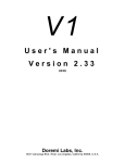
4 Rear Panel Description
DCT, MPEG2 and Uncompressed SD
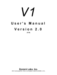
38
Uncompressed High Definition (HD)
39
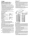
4.1
Video Inputs / Outputs >>DCT, MPEG2 & Uncomp SD
40
4.2
Note :
Do not use YUV/RGB output and Y/C (S-Video) outputs at the same
time because these signals are coming from the same buffered outputs
and this will produce a mismatch on impedance loads.
Sync In
House Sync input BNC connector for the V1 synchronization reference.
Use only Black Burst Sync here. Sync input should not exceed 1V P-P.
Video
Analog Composite video input and output BNC connectors. Video IN is
where you connect your video signal for recording to the V1 and Video
OUT is for connection to a video monitor or another video recorder.
S-Video
Two separate Y and C BNCs. You must use a Y/C to Mini DIN-4
adaptor for single cable S-VHS applications.
SDI (option)
Optional. Serial Digital Interface input and output BNC connectors
RGB/YUV (option)
Optional. Three RGB or YUV selectable BNC output connectors
Video Inputs / Outputs >>Uncomp. HDTV
HDSDI
Serial High Definition digital Video
Y Pb Pr
Analog Component High Definition Video
SYNC Input
Tri-level sync input. Locks the V1 to an external sync source
CVBS
Composite Video Reference Output – (Standard Video Resolution)
41
4.3
Audio Inputs / Outputs
Analog Audio
2 channel analog XLR inputs and outputs. These XLR connectors are the
balanced analog audio inputs and outputs. Pin 2 is hot (+), pin 3 is cold
(-), and pin 1 is ground.
Digital Audio (option) 4 channel digital XLR inputs and outputs. Transformer balanced
AES/EBU input and output. Pin 2 is hot (+), pin 3 is cold (-), and
pin 1 is ground.
Audio Expansion1
Expansion Card Slot holds one of the following optional cards
A- 4 Channels AES / EBU
B- 2 Channels analog audio
Audio Expansion2
Expansion Card Slot holds one of the following optional cards
A- 4 Channels AES / EBU
B- 2 Channels analog audio
Embedded Audio on SDI (option)
4.4
Up to 8 channels of audio can travel with the SDI video.
9 Pin Connectors
GPIO:
Optional. General Purpose inputs and outputs
RS-422-1:
Primary serial interface connector to the V1. Connector 1 should be
connected to your edit controller or workstation, while connector 2
can be used to connect the optional RCV2-9p external remote
control from Doremi Labs.
RS-422-2 / + Biphase:
If all 9 jumpers on J34 are set to the RS422 position, this connector will
be used as a second RS422 port (this is the default setting when the unit
is shipped). If all 9 jumpers on J34 are set to MIDI+BP position, this
connector will be used as a Biphase input with a +5V supply.
4.5
Ethernet Connector
Ethernet: RJ45 connector 100BaseT. You can set a unique IP address for the V1 in Option Menu
(00) INFO/MODE IP (no.)
4.6
Time Code
Balanced TRS 1/4" input and output connectors for LTC time code. The V1 time code input
accepts balanced signals (tip hot, ring cold & sleeve is ground). If you are feeding an unbalanced
signal to it, both ring and sleeve should be connected to GND. You can use an unbalanced jack
(tip and sleeve) on the time code input of the V1. The V1 time code output is a balanced signal
(tip hot, ring cold & sleeve is ground). If you are feeding it to an unbalanced input, ring should
42
not be connected to anything. You cannot use an unbalanced jack (tip and sleeve) on the time
code output of the V1. If you connect time code from one V1 to another the cable should be
balanced on both ends.
4.7
SCSI
Standard 68-pin female connector for connection to external SCSI drives. When no external
SCSI devices are used, make sure the supplied terminator is connected here. When connecting
external drives, the last drive in the chain should be terminated. All V1 internal drives supplied
by Doremi Labs, Inc. are non-terminated.
This connector may not appear on your unit because the terminator was placed inside the unit.
43
5 Menu Reference Chart
From the front panel, you have access to three different menus.
MENU:
OPTIONS MENU:
CONTROLLER MENU:
Press MENU
Hold OPTION and press MENU
Hold ESC and press MENU
Operation and navigation information are provided in the Chapter 6, 7 and 8.
5.1
Menu Chart
1 Control
Local | Remote
2 Time Mode
A Time | A Time DF | A Time as LTC | A Time LTC DF | Time Code | VITC Time
3 Sync Source
Internal for PAL or Internal 59.94 for NTSC | Auto | Sync In | Input
4 Chase Mode
Off | LTC | Serial TC | BiPhase
5 Vid Source
6 Aud Source
Composite | S-VHS | YUV | RGB | SDI
or
YPbPr | HD-SDI for High Def.
Analog | AES/EBU | SDI
HH:MM:SS:FF
7 INFO/T-LEFT
Audio Trck (no.)
Bit Rate (no.) Mbs
or
1:1 (no.) Bits
or
NTSC | PAL or ( HD Format )
Mode: 1R/P
also 1R-1P for MP2 and V1-UHD only
(no.) : 1
44
5.2
Option Menu Chart
1 TRANSPORT
DiskAcc PL-RE | Play
FrameMod On | Off | Play
StopMod Still | EE
Jog On Ch (no.) & (no.)
FastMod Norm | Enhan
JogSpeed FULL | 100%
PL1Field< % (no.)
ChaseFWL: (no.)
LimToSeg (no.)
LoopMode OFF | ON
Emulate ( V1 | DVW-500 | Odetics | Odetics LMTD | BVW-75| VDCP )
StepRec off | ALL | Video
Rec at: Cur P. | End F.
Segment#: (no.)
2 AUTO PLAY
NoVidDly 000s
BitRate (no.) Mbs or 1:1 (no.) Bit or (no.):1
NTSC | PAL or (HD Format)
3 NEW REC SET
# Aud Trks (no.)
Decimation | No Decimation for DCT & HD
GOP: I Only | IB | IP
for MPEG2
#Lines 480/512 NTSC | 576/608 PAL
Dur : HH:MM:SS
4 INIT DISK
MultiFile
Bus: (no.)
Stripe on: (no.)
#RaidSets: (no.)
bus:1, id: (no.)
5 SAVE SETNGS
6 SCSI SETUP
bus:2, id: (no.)
for High Def.
No | Are you sure?
SCSI ID (no.)
V1 Rec/Play | Play Only
Clock: 10 | 20 | 40 ( MHz )
Width: 8 Bit | 16 Bit
term'n: ON | OFF
Mount No | Are you sure?
Format No | Are you sure?
7 MEDIA SETUP
Init No | Are you sure?
8 DISK COPY
Copy ?
File (file name)
In: HH:MM:SS
Out: HH:MM:SS
Paste ?
Clear ?
45
Option Menu Chart Cont…
Vitc In Off | On
LumaCont:+ (no.)
LumaBrit:+ (no.)
ChromSat:+ (no.)
ChromHue:+ (no.)
CompBrit:+ (no.)
CompCont:+ (no.)
CompSat:+ (no.)
S.F. In: ON | OFF for High Def
Comb Filter ON | OFF for SD units
Out ( YUV | RGB | S Video )
CH PH (no.)
HTRIG off | on
HTRIG + (no.)
VTRIG + (no.)
Black 7.5IRE | 0.0IRE
PAL Sw itch 0
BIW Pos: (T/L | T/C | T/R | B/R | B/C | B/L)
BIW mode: (off | W-B | B-W )
Vitc Out Off | Line (no.)
CC Out Off | On
Pattern Off | On
S.F. Out: ON | OFF for High Def
Blank All | None
9 VID IN
10 VID OUT
11 AUD IN LVL
CH (no.): (no.) + db
12 AUD OUT LV
CH (no.): (no.) + db
A (no.): Off | On
TC: Off | On
Video Off | On
Assemble: Off | On
Insert: Off | On
Edit In: (no.)
13 EDIT PRST
Edit Out: (no.)
14 BI-PHASE
15 SERIAL PRT
#Clicks/Fr (no.)
1: P2 Protocol | 2: LD Protocol
2: P2 Protocol | 2: LD Protocol
46
Option Menu Chart Cont…
16 GPIO PORT
00 INFO/MODE
Disabled | Enabled
V1 (no.)
IP (no.)
Mask (no.)
S/N: (no.)
(no.) Megs RAM
Mode: 1R/P
also 1R-1P for MP2 and V1-UHD only
Netpos: None | Master | Slav e
47
5.3
Controller Menu Chart
01 Video
02 Composite Out
03 Burn In Window
04 Delay Mode
05 Preroll
06 Slomo Mode
ON | OFF
ON | OFF for High Def.
ON | OFF
ON | OFF for MP2 & HD 1R-1P
HH:MM:SS:FF for MP2 & HD 1R-1P
ON | OFF for MP2 & HD 1R-1P
07 Gang Mode
ON | OFF
08 4224 Clip Mode
ON | OFF
00 Firmware
RCV2 version (no.)
48
6 Menu
The V1 menu includes the most frequently used settings. Call up the V1 menu by pressing the menu up
" arrow key (or down key #). Use the arrow keys to scroll through the menu selections. The TOGGLE
button changes the parameters for the selected menu. Press TOGGLE increment or change a value and
hold OPTION and TOGGLE to decrease.
(1)
Control
This setting emulates the Local/Remote switch found on many Video Tape
Recorders and required by some remote control devices.
Local
Remote
(2)
Time Mode
For front panel control of the V1
For control of the V1 by an external edit controller or
workstation via the rear panel RS-422 connectors
Selects the Time Code source of the V1 during recording and playback.
Absolute Time, the time code displayed on the V1 front panel
and present on the TIME CODE OUT connector during
playback or record is generated internally by the V1. A Time
represents the time elapsed since the start of the recording
unless a time code offset has been set. See Section 2.8
A Time DF Absolute Time as above with Drop Frame. (NTSC Only)
A Time as If you are using A Time (with or without an offset) as your
time code and if your controller requires time code, you should
LTC
choose this option, which will make the A Time look like Time
Code on the RS422 connection.
A Time
Absolute Time as above with Drop Frame (NTSC Only)
LTC DF
Time Code
During record, the time code present on the TIME CODE IN
connector will be recorded on the time code track (guide track)
of the V1 active drive, a valid LTC signal should first be fed to
the V1 LTC IN connector. The time code displayed on the V1
front panel and present on the TIME CODE OUT connector
during playback or record is the same time code recorded on
the time code track, unless a time code offset has been set. See
Section 2.8
VITC Time During record, the time code embedded in the video input
signal (VITC) will be recorded on the VITC track of the V1
active drive. The time code displayed on the V1 front panel
and present on the VITC OUT connector during playback or
record is the same time code recorded on the VITC track,
unless a time code offset has been set. See Section 2.8
A Time
(03) Sync Source
Specifies the sync reference during playback. The V1 is always locked to the
Input when recording.
Internal
Internal
59.94
Auto
Sync In
Input
The V1 syncs to its own internal clock (PAL)
The V1 syncs to its own internal clock (NTSC)
The V1 syncs to the SYNC IN input.
The V1 syncs to the SYNC IN input. Auto and Sync In are the
same.
The V1 syncs to the VIDEO IN input.
49
MP2/MCS Only (Sync. Source) The sync source in units above 11000 is used to synchronize
both recording and playback. If the input is not locked to the sync source, a message will be displayed on
the 4 line LCD display of the recorder channel. For proper recording, the input must be locked to the sync
source selected on the V1. See the chart below for operation differences between units with serial number
above and below 11000.
Sync Source
Internal
Input
Sync in
Auto *
Units >11000 (1R-1P)
Recording: Not proper
Playback: Locked to internal
No SC Phase adjustment
Recording: Proper
Playback: Locked to input
No SC Phase adjustment
Recording: Proper only if input
is locked to sync in
Playback: Locked to sync in
SC Phase adjustment possible
Recording: Proper
Playback: Locked to sync in
SC Phase adjustment possible
Units <11000 (1R-1P)
Recording: Proper
Playback: Locked to input during record
No SC Phase adjustment
Recording: Proper
Playback: Locked to input
SC Phase adjustment possible
Recording: Proper
Playback: Locked to input during record
SC Phase adjustment possible
Recording: Proper
Playback: Locked to input during record
SC Phase adjustment possible
* Auto Mode: In this mode the unit normally works like sync in, but in certain conditions
outlined below it will change the way it locks.
• If the input disappears or becomes unlocked, the unit will display a message on the
record channel and starts to record black. The playback will continue normally.
When the input comes back, the unit will continue recording normally and the
playback will not be disturbed.
• If the sync in disappears, the unit will display a message on both channels, it will
stop and start the recording and playback for less than a second to lock record and
play to the input signal. When sync comes back, the unit will stop and start again to
lock to sync in.
• If both input and sync in disappear, the unit will stop and start to lock to internal, the
recording will be black and the playback will be normal. The unit will stay in
internal until sync comes back. If input comes back without sync, the unit will
continue recording black and will stay locked to internal
If you have a delay system and the input to the V1 was absent for 5 minutes, you can use the v1log.exe application
posted on our web site to capture messages with more information on what happened and when. This information can
be used to switch the output before the delay channel reaches the black area.
(04) Chase Mode
Specifies how the V1 will chase to time code.
Off
LTC
Serial TC
Biphase
Note:
Normal mode of operation when the unit is controlled by a
workstation via the 9 pin RS-422 connection.
In this mode the V1 will chase the time code fed through the
TIME CODE INPUT jack. This mode is recommended when
no RS422 9 pin control is present. See Section 2.6
In this mode the V1 will chase the time code received on the RS422 connection. This mode requires a special cable and it is
recommended only if no RS422 9 pin control is present.
In this mode the V1 will chase the Biphase input clock signal.
Option Menu (14) Bi-Phase should be set properly in order to
select the clock frequency.
To use the Biphase mode, jumpers on the main motherboard
should be set correctly. Please refer to Section 12.8
The Chase to LTC Mode above is different than the OPTION PLAY
Command also referred to as Chase Command (see section 2.6)
50
(05) Vid Source
Specifies which video input format of the V1 is active. Select between
COMPOSITE, S-VHS, YUV, RGB, SDI, HD-SDI, YPbPr. Formats available depend
on the V1 model and options you have installed.
(06) Aud Source
Specifies the audio input format. Select between Analog, AES/EBU or SDI (for
embedded audio on SDI). Formats available depend on the V1 model and options
installed.
AES/EBU Note: To ensure lossless audio on the digital input, it must be sampled
at 48.000Khz and phase locked to the video input. If you feed digital audio at a
different frequency, or if it is not phase locked to the video, the V1 will re-sample
the audio at 48Khz which may produce undesirable clicks.
(07) INFO/T-Left
This menu selection provides information on the current V1 settings. None of
these settings can be changed in this menu.
Will display how much time is still available on the disk
from the end of the existing recording. The total duration is
calculated using the disk capacity detected, the compression
rate, and the number of audio channels. After an Initialize
Command, T-Left displays the full capacity of the drive in
"HH:MM:SS:FF" format. If you call this menu during
recording, it will show the time left at the moment it was
activated. When the drive is fully recorded, "Time Left" will
display 00:00:00:00 and you are only allowed to record over
existing material. When this menu selection is active
pressing the ++ key will update the time left.
Audio Trck (no.) Displays the number of audio tracks available for record.
This setting changes if you create a new file or perform an
initialize command with a different audio track number
specified.
The information provided depends on the V1 model in use.
-> For Uncompressed 1:1 The sample bit rate is displayed
1:1 (no.) Bit
Bit Rate (no.)Mbs -> For MPEG2 the Mbs is displayed
-> For DCT compression the compression ratio is displayed
(no.) : 1
HH:MM:SS:FF
NTSC or PAL
HD Format
1R/P
1R-1P
NTSC or PAL is displayed for standard definition V1. And
the HD format for the High Definition video V1.
1R/P indicates the V1 can record or play
1R-1P indicates the V1 has a simultaneous record and play
engine installed.
51
7 Option Menu
To call up the Option Menu Hold the OPTION and press the MENU " (or down key #) buttons. Use
the arrow keys to scroll through the menu selections.
Use the ++ or -- buttons to scroll through the sub-menus. The TOGGLE button sets the parameters for
the selected sub-menu. Press TOGGLE to increase or increment a value and hold OPTION and
TOGGLE to decrease or use the JOG wheel.
TOGGLE is also used to execute a command (Option Menu 5 and 6), you will be prompted “are you
sure?” press ENTER for yes or ESC for no.
To enter time code numerals use the numeric keypad. To enter numbers for the IP, Time and Date use the
keypad and press the “.” button to skip from one section to the next (i.e. month to date). Press ENTER to
save your settings.
Commands that change the mode of operation, such as changing the IP, Subnet Mask, SCSI ID, rec/play
mode etc, will require you to reboot the V1. Please wait 30 seconds before rebooting the V1 to ensure
that the new settings take effect.
(00) Info/Mode
V1 (no.)
Displays the V1 Version number
IP and Mask below must be set to conform to your LAN so that you can operate the V1 and upgrade the
firmware via the Ethernet connection.
IP (no.)
Displays the current IP number of the V1. (Only part of the IP number is displayed,
to view the rest press TOGGLE)
Set the IP number by using the keypad. Press “.” to jump between the sections.
After inputting the IP numbers press ENTER. You will also need to go to
OPTION MENU (05) Save Setngs and save.
Wait 30 seconds and restart the V1 for the setting to take effect.
Mask (no.)
Displays the current IP number of the V1. (Only part of the IP number is displayed,
to view the rest press TOGGLE)
Set the Mask number by using the keypad. Press “.” to jump between the sections.
After inputting the Mask numbers press ENTER. You will also need to go to
OPTION MENU (05) Save Setngs and save.
Wait 30 seconds and restart the V1 for the setting to take effect.
The functions below provide general information about your V1. Please have this information on hand
prior to contacting Doremi tech support.
S/N: (no.)
Displays the unique serial number of your V1.
(no.) Megs RAM
The total RAM on the V1 motherboard.
Mode
1R/P: Indicates a standard record or play engine
1R-1P: Indicates a simultaneous record and play engine. MP2 & UnocmpHD only
To change the mode press the TOGGLE key and the hit ENTER. You will next
need to save your settings, wait 30 seconds and recycle power on the V1.
52
Netpos
None: For all units that are not sharing storage between channels except for dual
channel units that are set to 1R-1P modes.
Master: For MCS units with shared storage. Only one recorder channel should be
set to Master
Slave: For MCS units with shared storage. All channels should be set to Slave
except the Master.
To change the mode press the TOGGLE key and the hit ENTER. You will next need to save your
settings; wait 30 seconds and recycle power on the V1.
53
7.1
Transport
The Transport settings feature functions that affect the general playback and record operation of
the V1.
Disk Access
This option will allow you to write protect your drive. Select between Play
and PL-RE (Play & Record (Default). When Play is selected, you will not
be able to record on the disk or initialize it.
Frame Mode
Select between Frame Mode ON, OFF and Play.
When ON the V1 will stop on a frame and in slow motion it will play frame
by frame.
When OFF the V1 will stop on a field and in slow motion it will play field
by field.
In PLAY, the V1 will stop on a field and in slow motion it will play frame
by frame.
This setting also affects the Step Recording option. For Slow Motion
application, the frame mode must be OFF. When the V1 is in stop (freeze)
mode and Frame Mode is set to ON a full video frame will be displayed.
StopMod
Select the video output to be displayed after the V1 receives a stop
command. Set stop mode to either show a field/frame from the drive (Still)
or show the image present on its input (EE).
Jog On Ch
Select between “1&2”, “3&4”, “5&6” and “7&8”. When the V1 is playing
at any speed below 100%, the audio will output from only two channels. Use
this option to select which tracks the audio will be on when the V1 is
playing at any speed below 100%.
FastMod
Select between Norm (normal) and Enhan (enhanced). Enhanced mode will
provide the best video preview in Fast Forward and Fast Rewind
Set Fast Mode to Enhanced on all single channel units, the V1x2 with dual-drives
and the V1-MP2 in 1R/P mode.
Set to Normal for units connected to the V1Xserver and multi-channel units like
the V1x2-1r2p, V1-MP2-1r2p & 1r-1p, V1-UHD-1r-1p, V1-MP2 1r-1p.
JogSpeed
Sets the maximum speed in Jog mode to 100% or FULL (no limit).
PL1Field<%
The speed shown in percentage will define the speed under which the V1 will only
play odd fields. If you want to play odd and even fields at all speeds, select 0%.
For Slow Motion applications you must set this parameter to “0” and save it.
ChaseFWL:
The number of frames defined in this option will set the free-wheel of the chase
mode between 1 and 10 frames or “0”. If your time code is reliable set to “0”.
When set to a value between 1 and 10, the V1 will play the same field for the
specified amount of frame(s) before it stops and wait for the new time code to
chase.
54
This function is useful to reduce the audio noise during the chase command. If you
know that your source does not have drop-outs in the time code, set this value to 1.
LimToSeg
Limit to Segment; specifies the operation of “Loop Mode” below. When
“LoopMode” is set to ON, the V1 will record (play) in a loop specified by the
segment number. If the segment selected in this option is 0, the loop will be the
entire length of the file (24 hours).
LoopMode
Select between OFF and ON. When ON the V1 will loop back to beginning of the
recorded video when it reaches the end of the file or segment as specified in
“LimToSeg” above. When set to OFF the V1 will stop.
Emulate
Select between V1 (default), BVW-75, DVW-500, Odetics, Odetics LMTD and
VDCP (Louth).
StepRec
This option is for Step Recording. When enabled, every time the V1 goes into
record, it will only record one frame. This option is useful for animation. When
Step Recording is disabled, the V1 is in normal mode of operation.
Select ALL to record the video and audio. If you want to record video only
without altering the previously recorded audio, select Video.
Note: Step record cannot be enabled on the MPEG2 products
Rec at:
The function tells the V1 to record at the current position (Cur P.) or at the end of
the last recorded video in the file (End F.). If you are working in any of the ATime modes and want to avoid recording over existing material, set this option to
End F.
Note : Rec at: End F. is not valid if the Time Mode is set to Time Code or to
VITC. In those two modes, the unit will synchronize to the incomming time code
to determine the recording position.
7.2
Auto Play
The Auto Play settings allow the V1 to automatically start playing a segment when the V1 is powered on
and the drive is mounted.
Auto Play
Enter a predefined segment number. The V1 will now play that segment every time
it mounts that drive. This function can also be used to automatically locate to a
start point every time the disk is mounted. All you need to do is set the IN and
OUT time at the same location for the auto-play segment.
NoVidDly 000s
V1 Screen Saver. This parameter sets the delay until the video output goes black
(screen saver) in 10 second increments. "000" will disable this feature. Example:
"010" will cause the unit to output black video when the unit is idle for 10 seconds.
7.3
New Rec Set
The New Record Settings contain all the main options used to define a V1 File.
If you are using multiple files on the V1 you must create a new file after changing a setting in this
section. For instructions on how to create a file see section 2.2
55
If you are using a single file (the default file created by the V1) you will need to reinitialize after
changing a setting in this section. See section 7.7
The options below determine the amount of compression or the sample bit rate of the recording:
BitRate
MP2 Only Select the Mbs (Mega Bits Per Second) from 5 to 50Mbs. The higher
the number the better the video quality and more storage space required.
1:1 (no.) Bit
Uncomp SD & HD only Select 8bit or 10bit.
(no.) : 1
DCT Only Select the compression ratio. The smaller the ratio the better the video
quality and more storage space required.
The first three options below determine the Format of the recording, and the max number of audio tracks
to be recorded.
NTSC or PAL
Select NTSC or PAL resolution and frame rate. Applies to Standard Definition V1.
(HD Format)
UncompHD Only Select between the different HD formats.
720 59.94p
720 60p
1080 29.97p
1080 30p
1080 59.94i
1080 60i
1080 25p
1080 50i
1080 23.98p
1080 24p
1080 48i
1080 47.95i
Selects 720 line progressive 59.94 frame /sec standard
Selects 720 line progressive 60 frame /sec standard
Selects 1080 line progressive 29.97 frame /sec standard
Selects 1080 line progressive 30 frame /sec standard
Selects 1080 line interlaced 59.94 field /sec standard
Selects 1080 line interlaced 60 field /sec standard
Selects 1080 line progressive 25 frame /sec standard
Selects 1080 line interlaced 50 field /sec standard
Selects 1080 line progressive 23.98 frame /sec standard
Selects 1080 line progressive 24 frame /sec standard
Selects 1080 line interlaced 48 field / sec standard
Selects 1080 line interlaced 47.95 field/ sec standard
# Lines
Select between 480 or 512 for NTSC or 576 or 608 for PAL. This sets the total
number of lines recorded for NTSC or PAL.
No Decimation
Select between Decimation and No Decimation. For DCT units decimation will
record half the pixels. For HD units decimation will compress the component Pb
and Pr and leave Y uncompressed (411 encoding). When Decimation is selected
you will double your recording time on V1 DCT units and increase the recording
time by 25% on V1-UHD units.
GOP
MP2 Only Determines the type of MPEG2 compression to be used. There are
different performance and storage space trade offs between the three different
types offered.
# Audio Trks (no.)
Select between 2. 4. and 8 which designate the number of audio channels to be
recorded.
Dur:
The default value of this parameter is 24 hours (24:00:00) but it can be set to any
other value below 24 hours to define the time code length of the file. If you want a
file to start at 0 and end at 1 hour instead of 24 hours, you should set this
56
parameter to 01:00:00, hit ENTER then create a new file. This parameter can be
saved to flash and is essential for time delay applications.
7.4
Init Disk
The Initialize Disk settings will set the parameters and configuration of the drive(s). These settings are
preconfigured at the factory (when the drives are purchased from Doremi Labs) and typically will not
require change.
You must initialize the drive(s) after changing any of the settings in this section.
MultiFile Type
This option indicates that the drive will be initialized with Doremi’s Multi-File
System (MFS). This setting cannot be changed
Bus: (no.)
Select the number of SCSI buses to use. For all standard definition V1 this
should be set at 1. For the high definition it can be 1 or 2.
Stripe on: (no.)
Sets the number of disks in the RaidSets (see option below). This parameter
should be set to the total number of drives in the Raid set.
#RaidSets:(no.)
Sets the number of RaidSets to be defined. This parameter should be set to 1.
Bus1.id(no.)
Sets the first SCSI ID of bus 1. All other drive IDs for Bus 1 should be
consecutive to the first drive ID.
Bus2,id(no.)
UncompHD Only. Sets the first SCSI ID of bus 2.
7.5
Save Setngs
This menu option will save all the current menu settings of the V1 to the internal memory so that upon
restart the settings will be preserved. All saved settings will remain on the drive, so that if the drive is
placed in another V1 the settings will be preserved.
To write the settings to memory (Flash EPROM (see Note below), press TOGGLE. A message will
appear on the LCD screen: “Are you sure?”
♦ If you want to save, press ENTER. The V1 will write the changes on the Flash EPROM.
♦ If you change your mind and don't want to save, press ESCAPE.
NOTE: THIS FUNCTION SHOULD NOT BE ABUSED BECAUSE THE FLASH EPROM CAN
ONLY BE WRITTEN 2000 TIMES. If you save your settings on the flash EPROM more than 2000 times
you might damage it and need to replace it by sending the unit back to Doremi Labs.
7.6
SCSI Setup
The SCSI Setup settings will set the parameters and configuration of the drive(s). These settings are
preconfigured at the factory (when the drives are purchase from Doremi Labs) and typically will not
require change.
You must initialize the drive(s) after changing any of the settings in this section.
SCSI ID (no.)
Sets the SCSI ID number of the V1 after restart. Do not use a SCSI ID number
for the V1 that conflicts with any installed drive. The default SCSI ID is 7.
57
V1 (type)
Select between Rec/Play and Play Only. This option is used when more than one
V1 unit is connected to the same drive or RAID. You can only have one unit set in
Rec/Play and all the rest should be Play Only. The Rec/Player is the only unit
allowed to record.
Important Note: When the unit is in Play Only mode, all operations that write to
the active drive are denied, including record, initialize, format, etc.
The settings below are used to set the SCSI Parameters. Below are the recommended settings:
•
•
•
DCT and MPEG2 standalone units the settings should be: 20-16-ON.
V1-U settings should be: 40-16-ON
For units installed with the V1Xserver, the settings should be: 10-16-ON.
Note: For the MPEG2 and DCT units with a loop SCSI cable (2 SCSI connectors in the back),
the Termination should be OFF.
Clock
Used to set the SCSI speed in MHz; 10, 20 or 40
Width
Used to set the SCSI bus width; 8 bit or 16bit
Termination
Used to set the Termination mode; ON or OFF
Warning: You should not set the termination to off unless it was originally configured by Doremi
or when requested by a Doremi Labs technician.
7.7
Media Setup
To activate the commands in this section. Press TOGGLE. The message “Are you sure?” will
appear on the LCD screen. To accept press ENTER. If you change your mind press ESCAPE.
Mount
If you have more than one drive powered up, this command will mount the
drive with the highest SCSI ID number.
Format
This command deletes all previous recording and prepares the active drive for
optimal V1 performance. Brand new drives do not need formatting. The Format
command should always be followed by an Initialize command (see below).
When the format command is executed the LCD will display "Formatting..." and
will format the disk. Once done, "Formatting..." is cleared and the LCD displays
“No MD Present”. The drive is now ready for the Initialize operation.
CAUTION NOTE !!
Formatting a drive is a long procedure, please do not attempt to use the V1
until the format operation is complete and DO NOT SHUT OFF THE V1
DURING THE FORMAT OPERATION
If the V1 is switched off during the format operation, you will need to restart the
format operation.
CAUTION NOTE !!
Option Menu (04) Init Disk should be set properly before formatting a drive.
Once Format and Initialize have been executed on a drive, it is not
necessary to Format again. Initialize is enough for erasing the drive.
58
Init
The Initialize command deletes all previous recordings and files (clips), and writes
all the new set-up parameters selected in the menus on the active drive. A disk that
was never initialized on the V1 will display the message "No MD Present" until it
gets initialized.
CAUTION NOTE !!
Ensure that the settings under Option Menu (04) Init Disk are set properly before
initializing the drive.
7.8
Disk Copy
The Disk Copy functions will allow you to copy a whole file or a segment within the same disk or from
one disk to another. The copy operation is based on a Copy Paste approach.
•
•
•
•
•
•
•
•
•
Load the source file
Locate to the start of the segment you want to copy and hit IN (optional)
Locate to the end of the segment you want to copy and hit OUT (optional)
Go to Option Menu 8, the display should be “Copy ?”, hit ENTER to mark the segment or file for
copy.
The display will show you the file name and if you hit ++, it will show you the IN and OUT points
followed by the “PASTE ?” prompt.
Load the destination file
Locate to the timecode where you want the video to be pasted to
Go to Option Menu 8 and when you see the prompt “Paste ?” hit ENTER and the copy will start.
To copy another segment, go the “CLEAR ?” prompt, hit ENTER and repeat the above steps.
Line 2 of the LCD display will show the copy progress status. When done it will display the message
“Completed”.
To copy a file from one disk (or set of disks) to another, use the Mount command in Option Menu 7.
Every time you issue a Mount command, the unit will search all drives for valid V1 Multi File systems
and it will mount the next available one.
7.9
Vid IN
The Video Input settings below affect the video prior to recording on the drive.
VITC In
Luma Cont
Luma Brit
Chroma Sat
Chroma Hue
Comp Brit
Comp Cont
Comp Sat
Select off or the line number the source VITC is on
(10 to 18 for NTSC & 6 to 20 for PAL)
(Recommended Values: NTSC:14 - PAL:19)
Luma Contrast. Set value of the analog input.
Luma Brightness. Set value of the analog input.
Chroma Saturation. Set value of the analog input.
Chroma Hue. Set value of the analog input.
Composite Brightness. Set value of the analog input; Component YUV/RGB
Composite Contrast. Set value of the analog input; Component YUV/RGB
Composite Saturation. Set value of the analog input; Component YUV/RGB
59
S.F. In
Comb Filter
UncompHD only. Select between segmented and non-segmented frame on the
input. S.F. ON or S.F. OFF.
Select ON or OFF. Enables or disables the 3 line comb filter on the composite
video input.
7.10 Vid OUT
The Video Output settings below affect the video on the output (during playback from the drive)
Out
CH PH
HTRIG
HTRIG +
VTRIG +
Black 7.5 IRE
PAL Switch
BIW Pos
BIW mode
VITC Out
CC Out
Blank
Pattern
S.F. Out
Select the video format on the output (YUV, RGB, S Video)
See section 4.1 for information on what formats are available simultaneously.
Increase or decrease the chroma phase from 0 to 360.
Horizontal Trigger adjustment. Set the HTRIG adjustment ON or OFF.
Enter the Horizontal Trigger value.
Vertical Trigger adjustment. A positive number will move the picture
upwards, and a negative number downwards.
Used in NTSC only. Sets the black level to 0.0IRE for the Japanese
standards and 7.5IRE for the American standards.
Select 0 or 1. Set the value according to the PAL standard used in your area
(A or B)
Time Code Burn-in window. Position on the screen at Top-Left, Top-Center,
Top-Right, Bottom-Right, Bottom-Center, Bottom-Left
(Analog Video Outputs Only)
(For HD always present on the standard definition composite output.
Available on HD-SDI and YpbPr only when enabled)
Select between off, black on white, or white on black numerals.
Vertical Interval Time Code. Select off or the line number to output VITC on
(10 to 18 for NTSC and 6 to 20 for PAL)
(Recommended Values: NTSC:14 - PAL:19)
Close Caption. Set to on or off to allow close caption to pass through the V1.
(Analog and SDI Video)
Select all or none. Will either blank or show the extra lines for 512 line
(NTSC) or 608 line (PAL) recordings.
Video Pattern. Select on or off.
UncompHD Only. Select between segmented and non-segmented frame on
the output. S.F. On or S.F. off.
7.11 Aud IN LVL
Sets the audio input level for each analog audio channel separately.
7.12 Aud OUT LV
Sets the audio output level for each analog audio channel separately.
This feature is not yet enabled.
7.13 Edit Prst
The settings in Edit Presets allow for the insert/overdub of audio, time code or video individually, while
the non-selected track(s) are monitored at the same time. The settings are used for manual insertion.
This is not a recommended practice. Doremi Labs strongly recommends using an edit controller.
60
If you are using an edit controller the edit controller will set these options automatically. The settings
the edit controller has selected will be reflected here.
NOTE: For the V1-U the overdub feature is only supported on the Seagate Cheetah SCSI 15k RPM
drives. For the V1-MP2 & DCT you can use 10k RPM drives. For the V1-UHD it requires at least 4
15000 RPM drives or the dual-SCSI external drive setup.
Select the audio track number(s) and then select off or on. On indicates the
track will be overdubbed.
To insert/overdub time code on the guide track, select On.
To insert/overdub video, select On.
If this option is set to On, all the previous 3 submenus above will default to
the On position and the drive is set for normal recording (video, audio and
time code).
The reason for this option is to allow the V1 to record while in PLAY mode
(Usually required by Editors using RS422 control), in this case, the sub-menu
Assemble must be set to On.
Enables or disables the ability to insert video or audio using the front panel.
Specifies the Record delay for the IN point in number of frames. The V1 will
wait x frames before it starts recording after receiving an EDIT ON
command. For MPEG2 units this should be set to 5 or higher.
Specifies the Record delay for the OUT point in number of frames. The V1
will wait x frames before it stops recording after receiving an EDIT OFF
command. For MPEG2 units this should be set to 5 or higher.
A (no.):
TC
Video
Assemble
Insert
Edit In
Edit Out
7.14 Bi-Phase
Select between 01, 02, 04, 10. The selection represents the number of clicks on the incoming
Biphase signal per video frame (01= 1 click per frame). In PAL 25 frames/sec, 01=25Hz,
02=50Hz, 04=100Hz, 10=250Hz.
7.15 Serial Port
Defines the protocol used on the RS422 PORT1 and RS422 PORT2 located on the back of the unit. Each
port can be individually set to emulate:
P2 Protocol: Sony P2 protocol at 38400 bauds
LD Protocol: Pioneer Laser Disk Protocol at 4800 or 9600 bauds.
1:
2:
For Serial Port 1. Select P2 or the LD protocol
For Serial Port 2. Select P2 or the LD protocol
7.16 GPIO Port
For the General Purpose Interface (GPI) port on the back of the unit. Select between enabled and
disabled.
Note: GPI cannot be enabled if your V1 was not purchased with the GPI option. If the Option board is
not installed, this option menu should be disabled.
61
A future software release will allow the user to specify the functions of the 3 GPIs and GPOs. In the
current software the 3 GPIs are set to:
GPI 1: Play previous available segment (= Pin 1 to set at GND level),
GPI 2: Reset segment number to 0 (= Pin 7 to set at GND level),
GPI 3: Play next available segment (= Pin 3 to set at GND level).
GND
1
GPI3
3
GPO3
2
GND
4
GPI1
5
GPIO connector on Back Panel
GND
6
GPO2
7
GPI2
8
GPO1
9
GPI inputs are TTL ACTIVE LOW signals to be controlled by closing contacts: Contact closed
(Between GPI & GND) = Level 0 on that GPI = Command as listed
(Open GPI has a voltage of TTL high level so between 3.5 & 5V)
The V1 sends a trigger signal to either GPO pin number 1, 2 or 3 after it completes the playback
of a segment. The GPO pin number the trigger is sent to is determined by the remainder value
when dividing the segment number by the number three.
If remainder is 1 the trigger is sent to GPO1
If remainder is 2 the trigger is sent to GPO2
If remainder is 0 the trigger is sent to GPO3
62
8 Controller Menu
The front panel controls of the V1 are called the “RCV2 controller”. The RCV2 controller
communicates with the V1 via RS-422. The controller has several unique functions. To call up the
Controller Menu hold the ESCAPE button and press the menu up " arrow key (or down key #). Use the
arrow keys to scroll through the menu selections. The TOGGLE button changes the parameters for the
selected menu. Press TOGGLE to increase the parameter and hold OPTION and TOGGLE to decrease
the parameter.
To disable the RCV2 and prevent accidental operation, hold the OPTION button then press ESCAPE.
Press again to unlock the RCV2. When the RCV2 is in “disable mode” the letters “DIS” will be
displayed in the top right corner of the 4 line LCD.
To reset the controller (soft reset) hold the 1,2,3 or 4 buttons and press CLEAR. This may be
necessary to reset the optional Video LCD display if you switch between NTSC & PAL formats.
(00)
RCV2 Version
Displays the firmware version number for the RCV2 controller.
(01)
Video
Use the TOGGLE button to switch the front panel LCD monitor
“on” or “off”. Default is “on”
(02)
Composite Out
For V1-UHD only. Switches the composite output on the rear
panel of the V1-UHD “on” or “off”. Default is “on”.
(03)
Burn In Window
When ON, the burn in window will be enabled on the confidence
LCD monitor (it needs to also be enabled in the Option Menu
setting). - Defualt is “on”.
(UncompHD Only – Always active on LCD monitor and on
composite output)
(04)
Delay Mode
Dual-channel V1x2 configured for single drive operation or
V1-MP2 1R2P or V1-UHD 1R2P.
This is used for broadcast delay to define the time delay between
the recorder and the player(s). Ensure that the V1 is not recording.
Select the player (channel 2) and enter the delay time desired and
press ENTER. The record and play channel will locate to 0 time
code, the recorder will start recording and the player will wait for
the time set for delay to elapse, and will then start playing back
automatically.
The transport controls on the player (channel 2) will be disabled
when the time delay function is engaged. To stop the delay
function select the recorder (channel 2) and press STOP.
Default is “off”.
(05)
Preroll
Used in conjunction with Slomo Mode (See below). When a time
value is entered the RCV2 identifies the pre-roll time from the
location point. This helps to compensate for the delay between the
action being recorded and the push of the save button.
63
(06)
Slomo Mode
Dual-channel V1 configured for single drive operation or V1MP2 & HD 1R-1P only .
Used for sports slow motion replay applications. When ON, the
RCV2 operates like a slow motion controller.
Note: To use Slom Mode, ensure that Menu (02) Time Mode is set
to A-Time. To operate with Time Code, you will need to use an
external controller.
Select Channel 1. Go to the start of the disk by pressing CLEAR
then press GOTO, then start recording.
Select Channel 2 and press the Record button to go in EE mode.
When you see an event worth marking press SAVE, this will
increment the Segment number and save the IN point of the
clip minus the Preroll value setting. (see Preroll above)
Every time you hit SAVE, the Segment number will increment
and the new time code will be captured.
If you want to recall a specific segment press the ++ or – buttons
until you see the desired Segment number displayed, then press
RECALL. (You can do this while in EE mode)
When you press SloMo, the unit will start playing from that point
at the slow motion speed selected by the Shuttle wheel.
To stop and go back in EE, press STOP followed by the RECORD
button.
Default is “off”.
(07)
Gang Mode
Dual-channel V1 only or control of two single channel V1
decks. When ON, it will insure that both channels are always at
the same time code location. Used to synchronize the recording
and playback operation of two channels. Default is “off”.
(08)
4224 Clip Mode
Dual-channel V1 only or control of two single channel V1
decks. For applications such as logo insertion plus key. Allows
you to record Logo plus Key separately, then find the in points and
make clips that are locked together.
In this mode the RCV2 will insure that all clips are created with the
same duration on both channels, the only distinction is that the IN
and Out points will be different.
Define the IN and OUT on Channel 1, then define the IN only on
channel 2 and hit SAVE clip# ENTER. The RCV2 will
automatically calculate the duration from channel 1 and create an
equal length clip on channel 2. When you RECALL clip# ENTER,
the unit will play both clips synchronously even if they don't have
the same start time. Default is “off”.
64
9 Troubleshooting Information
9.1
Unable to control V1 remotely
If you have a normal RS422 9 pin control connection and you cannot control the V1, check Menu (4)
Chase Mode. It should be set to OFF. In addition, ensure that the controller protocol and the emulation
mode match. (Option Menu (01) Transport Emulate and Option Menu (15) Serial Port)
9.2 Recording in case of tape drop-out
When recording with external timecode, two kinds of drop-out might occur:
♦ If the time code drops out but the video signal is still valid, the V1 will keep recording the
timecode (it will free-wheel for 4 frames and then records any right or wrong time code fed
on the TIME CODE IN jack) and the valid video signal.
♦ If the video signal is not valid, the V1 will 'pause' (stop recording but will stay in record
mode) until the video signal becomes valid, then the V1 will continue recording. This case
may result in bad video/audio recording. We recommend using a frame synchronizer for
video, and delay the audio by the same amount if needed.
9.3
V1 identification for editors and DAW on the RS422 port
The V1 can reply with two different Machine Ids when connected to a controlling device like a Sony 9Pin editor.
If Option Menu (1) Transport is set to BVW75, it will reply with a "BVW75" identification.
If Option Menu (1) Transport is set to V1 (default), the V1 will reply with a "V1" identification.
If Option Menu (1) Transport is set to DVW-500, the V1 will reply with a "DVW500" identification.
Caution note: Some DAWs or Editors will not initialize the RS422 port correctly if the Id returned on
the RS422 port is unknown by them. In this case, set the EMULATION to BVW75.
9.4
The Video has no colors
If the video is not stable and is not displaying colors properly, you have set the Menu (3) Sync Source
to Auto or Sync In but you do not have a black burst signal fed to the SYNC IN connector. If the video
stabilizes when you switch to Internal, the problem is definitely your Sync Source setting.
9.5
No Audio from input monitor
If you cannot hear the audio when you go in input monitor, check the Option Menu (11 & 12) for your
Audio Levels and check the audio input source menu.
9.6
Unable to write to active drive
If you are not able to write to your active drive, i.e. cannot record, initialize or format, check Option
Menu (6) SCSI Setup and set V1 to Rec/Play
9.7
Forcing power ON in any condition
The V1 can be set to remain on even if AC power is cycled OFF then ON again. To force a “always ON”
operation please consult our tech support department.
65
10 TECHNICAL SUPPORT
Technical Support Contact Information:
On the web: www.doremilabs.com select the “support” button
Tel. 818 562-1101
Fax. 818 562-1109
Email [email protected]
306 E. Alameda Ave,
Burbank, CA 91502
U.S.A.
66
11 WARRANTY
Doremi's warranty obligations are limited to the terms set forth below:
Doremi Labs, Inc. ("Doremi") warrants this hardware product against defects in materials and workmanship for a period of ONE (1)
YEAR from the date of original retail purchase.
If you discover a defect, Doremi will, at its option, repair, replace, or refund the purchase price of this product at no charge to you,
provided you return it during the warranty period, with transportation charges prepaid, to the authorized Doremi distributor from
whom you purchased it or to any other authorized Doremi distributor within the country of original retail purchase. (You can obtain
additional information by contacting Doremi at the address printed on this certificate). To each product returned for warranty
service, please attach your name, address, telephone number, and a copy of the bill of sale bearing the appropriate Doremi serial
numbers as proof of date of the original retail purchase.
If your product fails during the warranty period while you are out of the country of original retail purchase, you may have it repaired
(no refunds or replacements are provided) at your expense by an authorized Doremi distributor in the country in which the product
failed. You may obtain a refund for the repair costs by submitting a claim to Doremi (instructions are obtained by contacting Doremi
at the address printed on this certificate).
This warranty applies only to hardware products manufactured by or for Doremi that can be identified by the "Doremi" and “V1”
trademark, trade name, or logo affixed on them. Doremi software is warranted pursuant to a separate written statement packed with
the software. Doremi does not warrant any products that are not Doremi products. This warranty does not apply if the product has
been damaged by accident, abuse, misuse, or misapplication; if the product has been modified without the written permission of
Doremi; or if any Doremi serial number has been removed or defaced.
THE WARRANTY AND REMEDIES SET FORTH ABOVE ARE EXCLUSIVE AND IN LIEU OF ALL OTHERS, WHETHER ORAL
OR WRITTEN, EXPRESS OR IMPLIED. DOREMI SPECIFICALLY DISCLAIMS ANY AND ALL IMPLIED WARRANTIES,
INCLUDING, WITHOUT LIMITATION, WARRANTIES OF MERCHANTABILITY AND FITNESS FOR A PARTICULAR PURPOSE.
No Doremi distributor, agent, or employee is authorized to make any modification, extension, or addition to this warranty.
DOREMI IS NOT RESPONSIBLE FOR SPECIAL, INCIDENTAL, OR CONSEQUENTIAL DAMAGES RESULTING FROM ANY
BREACH OF WARRANTY, OR UNDER ANY OTHER LEGAL THEORY, INCLUDING BUT NOT LIMITED TO LOST PROFITS,
DOWNTIME, GOODWILL, DAMAGE TO OR REPLACEMENT OF EQUIPMENT AND PROPERTY, AND ANY COSTS OF
RECOVERING, REPROGRAMMING, OR REPRODUCING ANY PROGRAM OR DATA STORED IN OR USED WITH DOREMI
PRODUCTS.
67
12 APPENDIX
12.1 Instructions for Initial Setup and Transport
Before any transport :
♦
Lock the Data-Express (Key ON as for normal use).
Note: Doremi highly recommends shipping drives separately.
♦
Switch the V1 OFF.
♦
Remove the SCSI termination on rear (Leaving it in may break the SCSI connector
during transport).
12.2 Upgrading the V1 firmware
The V1 firmware can be checked by going to the Option Menu. Scroll with the menu arrow keys
until you reach Option Menu (00) Info/Mode.
The V1 firmware can be upgraded from a PC or Mac using the VUploader utility posted on our
support page at: http://www.doremilabs.com
The latest firmware upgrades are posted on the support page of the Doremi web site:
The manual for VUploader is included in pdf format with the VUploader compressed file.
12.3 Upgrading the RCV2 firmware
All silver V1 decks have two firmwares, one for the V1 motherboard and another for the front panel (the
RCV2).
Check your RCV2 firmware version
Enter the Controller Menu by holding the ESCAPE button and pressing MENU. Scroll to Firmware.
The VUploader utility
The RCV2 can be upgraded using the VUploader utility version 1.08 or higher. Download the VUploader
utility from www.doremilabs.com in the support page.
Connect the 9pin cable between the RCV2-9P port labeled RS422 (1-2) (do not use the port labeled
RS422 (3-4)) to any of the ports on the back panel of your V1 deck.
Check that your V1 is running firmware version 4.16c or higher. If not use VUploader to upgrade it first.
Power up the unit while holding the Channel 1 button under the 4 line LCD display, you should see a
message saying "Flash mode"
Run VUploader. For detailed instructions see the VUploader README file that comes with VUploader.
When you receive the message from VUploader asking to select a port, choose the RS422 port that you
connected to on the back of the V1.
68
12.4 DCT Compression Chart
(H:M:S)
NTSC DCT Compression according to CCIR-601
Compression
Ratio
2:1
2.5:1
3:1
3.5:1
4:1
5:1
6:1
7:1
8:1
9:1
10:1
12:1
14:1
16:1
20:1
24:1
34:1
18GB
36GB
73GB
147GB
27:38 0:55:16
34:16 1:08:32
39:48 1:19:36
47:28 1:34:56
56:06 1:52:12
1:04:56 2:09:52
1:17:08 2:34:16
1:28:10 2:56:20
1:42:50 3:25:40
1:52:12 3:44:24
2:03:24 4:06:48
2:17:08 4:34:16
2:34:16 5:08:32
2:56:20 5:52:40
3:25:42 6:51:24
4:06:50 8:13:40
5:08:34 10:17:08
1:50:32
2:17:04
2:39:12
3:09:52
3:44:24
4:19:44
5:08:32
5:52:40
6:51:20
7:28:48
8:13:36
9:08:32
10:17:04
11:45:20
13:42:48
16:27:20
20:34:16
3:41:04
4:34:08
5:18:24
6:19:44
7:28:48
8:39:28
10:17:04
11:45:20
13:42:40
14:57:36
16:27:12
18:17:04
20:34:08
23:30:40
27:25:36
32:54:40
41:08:32
180GB
360GB
1.26TB
2.16TB
External Drive Chassis
04:36:20
9:12:40
05:42:40 11:25:20
06:38:00 13:16:00
07:54:40 15:49:20
09:21:00 18:42:00
10:49:20 21:38:40
12:51:20 25:42:40
14:41:40 29:23:20
17:08:20 34:16:40
18:42:00 37:24:00
20:34:00 41:08:00
22:51:20 45:42:40
25:42:40 51:25:20
29:23:20 58:46:40
34:17:00 68:34:00
41:08:20 82:16:40
51:25:40 102:51:20
32:14:20
39:58:40
46:26:00
55:22:40
65:27:00
75:45:20
89:59:20
102:51:40
119:58:20
130:54:00
143:58:00
159:59:20
179:58:40
205:43:20
239:59:00
287:58:20
359:59:40
55:16:00
68:32:00
79:36:00
94:56:00
112:12:00
129:52:00
154:16:00
176:20:00
205:40:00
224:24:00
246:48:00
274:16:00
308:32:00
352:40:00
411:24:00
493:40:00
617:08:00
69
PAL DCT Compression according to CCIR-601
Compression
Ratio
2:1
2.5:1
3:1
3.5:1
4:1
5:1
6:1
7:1
8:1
9:1
10:1
12:1
14:1
16:1
20:1
24:1
34:1
18GB
36GB
73GB
147GB
180GB
27:40
33:40
44:44
50:50
56:56
1:07:18
1:17:56
1:26:28
1:38:44
1:53:56
2:03:26
2:28:06
2:44:34
3:05:08
3:31:36
4:06:52
4:56:14
0:55:20
1:07:20
1:29:28
1:41:40
1:53:52
2:14:36
2:35:52
2:52:56
3:17:28
3:47:52
4:06:52
4:56:12
5:29:08
6:10:16
7:03:12
8:13:44
9:52:28
1:50:40
2:14:40
2:58:56
3:23:20
3:47:44
4:29:12
5:11:44
5:45:52
6:34:56
7:35:44
8:13:44
9:52:24
10:58:16
12:20:32
14:06:24
16:27:28
19:44:56
3:41:20
4:29:20
5:57:52
6:46:40
7:35:28
8:58:24
10:23:28
11:31:44
13:09:52
15:11:28
16:27:28
19:44:48
21:56:32
24:41:04
28:12:48
32:54:56
39:29:52
04:36:40
05:36:40
07:27:20
08:28:19
09:29:20
11:12:59
12:59:20
14:24:39
16:27:20
18:59:20
20:34:20
24:41:00
27:25:40
30:51:20
35:16:00
41:08:40
49:22:20
360GB
1.26TB
2.16TB
External Drive Chassis
9:13:20
11:13:20
14:54:40
16:56:38
18:58:40
22:25:58
25:58:40
28:49:18
32:54:40
37:58:40
41:08:40
49:22:00
54:51:20
61:42:40
70:32:00
82:17:20
98:44:40
32:16:40
39:16:40
52:11:20
59:18:13
66:25:20
78:30:53
90:55:20
100:52:33
115:11:20
132:55:20
144:00:20
172:47:00
191:59:40
215:59:20
246:52:00
288:00:40
345:36:20
55:20:00
67:20:00
89:28:00
101:39:48
113:52:00
134:35:48
155:52:00
172:55:48
197:28:00
227:52:00
246:52:00
296:12:00
329:08:00
370:16:00
423:12:00
493:44:00
592:28:00
Restrictions:
Due to drive speed variations, the following drives should not have a total record time lower than the
value specified in this table:
Due to drive speed variations, the following drives can only be used at the compressions specified in this
table:
Drive type
ST34371N/W
ST34572N/W
ST19171N/W
ST34501N/W
ST19101N/W
Minimum Compression Ratio (2 Fields)
4:1 or higher
3:1 or higher
ST34573N/W/LW
ST39173N/W/LW
ST39175LW
ST118273N/W/LW
ST318275W/LW
ST136475LW
ST150176LW
All newer Barracuda
2.5:1 or higher
ST34502LW
ST39102LW
ST39103LW
ST118202LW
ST318203LW
ST136403LW
ST373405LW
All newer Cheetah
2:1 or higher
70
12.5 MPEG2 Compression Chart
(H:M:S)
NTSC MPEG2 Compression at 720x480
Compression
Bit Rate
50 Mbit/s
45 Mbit/s
40 Mbit/s
35 Mbit/s
30 Mbit/s
25 Mbit/s
20 Mbit/s
15 Mbit/s
12 Mbit/s
10 Mbit/s
8 Mbit/s
5 Mbit/s
18GB
36GB
73GB 147GB
180GB
360GB
1.26TB
2.16TB
External Drive Chassis
0:40:46
0:45:14
0:50:38
0:57:41
1:06:46
1:19:17
1:38:02
2:07:33
2:36:41
3:04:15
3:43:35
5:26:13
1:21:32
1:30:28
1:41:16
1:55:22
2:13:32
2:38:34
3:16:04
4:15:06
5:13:22
6:08:30
7:27:10
10:52:26
2:43:04 5:26:08
3:00:56 6:01:52
3:22:32 6:45:04
3:50:44 7:41:28
4:27:04 8:54:08
5:17:08 10:34:16
6:32:08 13:04:16
8:30:12 17:00:24
10:26:44 20:53:24
12:17:00 24:34:00
14:54:20 29:48:40
21:44:52 43:29:44
6:47:40
7:32:20
8:26:20
9:36:50
11:07:40
13:12:50
16:20:20
21:15:30
26:06:50
30:42:30
37:15:50
54:22:09
13:35:20
15:04:40
16:52:40
19:13:40
22:15:20
26:25:40
32:40:40
42:31:00
52:13:40
61:25:00
74:31:40
108:44:18
47:33:40
52:46:20
59:04:20
67:17:50
77:53:40
92:29:50
114:22:20
148:48:30
182:47:50
214:57:30
260:50:50
380:35:03
81:32:00
90:28:00
101:16:00
115:22:00
133:32:00
158:34:00
196:04:00
255:06:00
313:22:00
368:30:00
447:10:00
652:25:48
1.26TB
2.16TB
PAL MPEG2 Compression Chart at 720x576
Compression
Bit Rate
50 Mbit/s
45 Mbit/s
40 Mbit/s
35 Mbit/s
30 Mbit/s
25 Mbit/s
20 Mbit/s
15 Mbit/s
12 Mbit/s
10 Mbit/s
8 Mbit/s
5 Mbit/s
18GB
36GB
73GB 147GB
180GB
360GB
External Drive Chassis
0:40:48
0:45:13
0:50:41
0:57:40
1:06:53
1:19:35
1:38:15
2:08:22
2:37:05
3:03:40
3:43:10
5:27:06
1:21:36
1:30:26
1:41:22
1:55:20
2:13:46
2:39:10
3:16:30
4:16:44
5:14:10
6:07:20
7:26:20
10:54:12
2:43:12 5:26:24
3:00:52 6:01:44
3:22:44 6:45:28
3:50:40 7:41:20
4:27:32 8:55:04
5:18:20 10:34:40
6:33:00 13:06:00
8:33:28 17:06:56
10:28:20 20:56:40
12:14:40 24:29:20
14:52:40 29:45:20
21:48:24 43:36:48
6:48:00
7:32:10
8:26:50
9:36:40
11:08:50
13:15:50
16:22:30
21:23:40
26:10:50
30:36:39
37:11:40
54:31:00
13:36:00
15:04:20
16:53:40
19:13:20
22:17:40
26:31:40
32:45:00
42:47:20
52:21:40
61:13:18
74:23:20
109:02:00
Note: This table is compiled for video at the indicated bit rate with 2 audio channels.
You can use any Seagate Cheetah hard disk that ends with the extension LW or a Barracuda 180gig.
If you are planning to do insert editing, use only Cheetah 15000RPM drives(X15) like the ST318452 and ST336752.
47:36:00
52:45:10
59:07:50
67:16:40
78:01:50
92:50:50
114:37:30
149:45:40
183:15:50
214:16:33
260:21:40
381:37:00
81:36:00
90:26:00
101:22:00
115:20:00
133:46:00
159:10:00
196:30:00
256:44:00
314:10:00
367:19:48
446:20:00
654:12:00
71
12.6 Standard Definition Uncompressed Chart
Uncompressed Recording Time
Model Number
V1-Ux2-23 per channel
V1-U-46
V1-U-93
V1-U-186
360GB
1.26TB
2.16TB
8Bit
10Bit
Drive Qty
36 GB
1 0:29:03 0:23:21
36GB
2 0:58:07 0:46:43
73 GB
2 1:56:14 1:33:25
147 GB
2 3:52:28 3:06:50
With External Storage Chassis
360GB
1 4:50:35 3:53:34
1260GB
1 16:57:02 13:37:27
2160GB
1 29:03:30 23:21:21
Drive Size
12.7 High Definition Uncompressed Chart
Model#
14R
29R
78
31T
62E
125E
219E
Drive Size
36 GB
3
73 GB
3
147 GB
4
73 GB
4
73 GB
8
147 GB
8
147 GB
14
Drive Qty
HD Format
1080 50i
or
1080 25p
Bit Coding
8 411
8 422
10 422
0:23:32
0:17:39
0:14:07
0:47:03
0:35:17
0:28:15
2:05:28
1:34:06
1:15:19
1:02:44
0:47:03
0:37:40
2:05:28
1:34:06
1:15:19
4:10:57
3:08:13
2:30:38
7:19:09
5:29:22
4:23:37
1080 60i
or
1080 30p
8
8
10
411
422
422
0:19:36
0:14:42
NA
0:39:13
0:29:25
NA
1:44:34
1:18:25
NA
0:52:17
0:39:13
0:31:22
1:44:34
1:18:25
1:02:45
3:29:08
2:36:51
2:05:30
6:05:59
4:34:29
3:39:37
1080 48i
or
1080 24p
8
8
10
411
422
422
0:24:31
0:18:23
0:14:42
0:49:01
0:36:46
0:29:25
2:10:43
1:38:02
1:18:26
1:05:22
0:49:01
0:39:13
2:10:43
1:38:02
1:18:26
4:21:27
3:16:05
2:36:51
7:37:31
5:43:09
4:34:30
720 60p
8
8
10
411
422
422
0:21:56
0:16:27
NA
0:43:52
0:32:54
NA
1:56:58
1:27:44
NA
0:58:29
0:43:52
0:35:20
1:56:58
1:27:44
1:10:39
3:53:57
2:55:28
2:21:19
6:49:24
5:07:03
4:07:18
V1-U: (46, and 93 versions) Use two DE300i-SWC160/B with Seagate Cheetah 15000RPM drives that
end with the LC extension. If the V1-U is equipped with ST318452 or ST336752, it can be initialized in
Single File system, which does not allow striping but allows daisy chaining and allows for the clips to be
saved on the drive.
V1-U-231: Use two DE100i-SWC160/B
V1-UHD: Internal non-removable, use Seagate Cheetah 15000RPM drives that end with the LW
extension
V1-UHD: External removable, use Seagate Cheetah 15000RPM drives that end with the LC extension.
72
12.8 BiPhase Settings
Pin 5: +5V will provide a 5V power signal
Pin 4: Biphase S signal
Pin 9: Biphase R Signal
Pin 1: Ground Signal
The rest of the pins are used for MIDI chase,
which is still not implemented.
TX
MIDI2
GND
1
RX
MIDI+
3
BP-S
4
+5V
5
DVP400
GND
6
TX
MIDI+
7
RX
MIDI8
BP-R
9
12.9 Connecting V1 to Audio Workstations & Edit Controllers
Most Common Connection
This connection scheme is used to connect the V1 to StudioFrame, Audiofile, Audiovision, Post-Pro,
Dyaxis II, Protools 4.0 etc.
1. Feed house sync to the V1 and the DAW,
2. Connect the time code out of the V1 to the time code in of the DAW,
3. Connect the serial cable between the V1 RS422 port 1 and the DAW,
Run the DAW software which will control the V1.
Connection to the DAWN workstation (v 4.3c or later)
1.
2.
3.
4.
5.
6.
7.
8.
9.
10.
Feed house sync to the V1 and the DAWN
Connect the time code out of the DAWN to the time code in of the V1
Connect the RS422 port 1 of the V1 to one of the serial ports on the Macintosh
Make sure the V1 is in Chase Off mode
Make sure the V1 Sync source is “Auto”
Run the DAWN software
You should see a V1 track at the bottom of the mix view
Make sure House Sync is checked
Toggle Master/Slave and then make sure you end up in master mode
Hit play, both units should play in sync
73
11. Hit Stop, both unit should stop.
The DAWN should always be in master mode.
Connection to the Akai DD-1500 with RS422 control (recommended)
1. Use the standard RS422 direct cable male-male 9 pins (Master to Slave)
2. Feed House Sync to the V1 and to the DD1500
3. Connect the serial cable between the V1 RS422 port 1 and the DD1500
4. Set the DD1500 Word Sync to Video A (29.97 for NTSC, 25fps for PAL)
5. Set the Ext M/C of the DD1500 to Master
6. Make sure the V1 is in Chase Off mode
Please contact Akai to get the best connection with the DD-1500 and the DD-8.
Connection to the Akai DD-1500 in CHASE RS422 Mode
1. If you did not receive a special serial cable that is DB9 Male to Male specific to the DD1500, you
need to make one with the following pin-out (This is a twisted Slave to Slave cable) :
pin 1 -> pin 1
pin 2 -> pin 8
pin 3 -> pin 7
pin 4 -> pin 6
pin 5 -> pin 5
pin 6 -> pin 4
pin 7 -> pin 3
pin 8 -> pin 2
pin 9 -> pin 9
2. Feed house sync to the V1 and to the DD1500
3. Connect the serial cable between the V1 RS422 port 1 and the DD1500
4. Set the DD1500 Word Sync to Video A (29.97 for NTSC, 25 fps for PAL),
5. Set the Ext M/C of the DD1500 to Full Slave,
6. Set the Chase mode of the V1 to Serial TC.
Use the DD1500 as if it is standalone, the V1 will chase to it at any speed.
Connection to the Fairlight
1. Feed House Sync to the V1 and the Fairlight
2. Connect the serial cable between the Fairlight and the V1 RS422 port 1
3. On the V1, set Option Menu (1) Transport JogSpeed to 100% (No Limit) and save using Option
Menu (5).
4. Run the Fairlight software, Hit the Machine 1 button to put the V1 on-line
5. Push buttons for setup of M1
6. Set Lace parameters to UNLACE=ON
7. And the LACE time parameter to 0 SEC
The Fairlight software will control the V1 properly
Connection to the Microlynx, the Lynx 1 and Lynx 2 synchronizers
1.
2.
3.
4.
5.
6.
Feed house sync to the V1 and the lynx,
If you are using a Lynx 1, connect the time code out of the V1 to the time code in of the Lynx
Connect the transport serial cable between the Lynx and the V1
In the Transport menu, select the machine as DVR10.
Set the Preroll to zero
If you are using a Microlynx or a Lynx 2, select Serial TC.
The Lynx will control the V1 and lock it to the system
74
Connection to the Sonic Solutions
1.
2.
3.
4.
Feed house sync to the V1 and the Sonic Station,
Connect the time code out of the V1 to the time code in of the Sonic,
Connect the serial cable between the V1 RS422 port 1 and the Sonic,
Select D-2 as the type of machine in the Sonic Machine list
The Sonic software will control the V1.
Connection to the Pro-Tools 4.0
Establishing Machine-control from Protools on the Macintosh
1. Connect the 9 pin RS422 cable between the V1’s lower RS422 port and the Macintosh’s Modemport, Printer-port or G-Port serial port. You can also connect it to the serial port on your D24 or MIX
card, but note that the VTPRO software will NOT operate through this port.
2. Connect the V1 LTC output to your LTC-to-MTC converter (for example: MOTU’s MTP2 / MTPAV, Opcode Midi interfaces, Digidesign USD etc.)
3. Connect the LTC-to-MTC converter to your Macintosh. In doing so, check that your Macintosh
receives MTC data from your interface.
4. Install Digidesign’s PostView or Machine Control Option on your Macintosh.
5. Power-up the V1. Make sure it operates correctly.
6. After your V1 has booted, run the Protools software.
7. Select the Machine-Control menu (Protools -> Setups -> Peripherals -> Machine Control).
8. Enable “9-pin serial”. If it’s grayed-out, try re-installing your Machine-Control software.
9. Under “Port”, select the serial port that you connected your V1 to (see step 1).
10. Under “Machine Type”, select “Sony-9 pin”
11. Under “Node”, select “V1”.
12. Under “Pre-Roll”, set Pre-Roll to 30 frames
13. Select the Synchronization menu (Protools -> Setups -> Peripherals -> Synchronization)
14. Under “Device”, select the correct LTC-to-MTC converter. If you’re not using a Digidesign device to
perform this function, select “Generic MTC reader”.
15. Under “Port”, select the serial or USD port that you connected your LTC-to-MTC converter to.
16. Set “Minimum sync delay” to 30 frames.
17. Select Protools -> Setups -> Preferences -> Operation. Activate “Machine Follows
Selection/Scrub”
18. Locate the Transport Control on your screen. If you don’t see it, select Protools -> Display -> Show
Transport
19. Make sure “transport = protools” is set and that the “online” button (the one that looks like a clock)
is selected.
20. Select Protools -> OMS Midi. Please be sure to deselect the serial port used by Protools for V1
control to avoid a conflict with OMS operation.
Protools will now be able to control the V1. The way it works is as followed:
• You hit play in Protools
• Then Protools will cue the V1 to the current play location MINUS the amount of frames set in
step 12
• Next, the V1 will send LTC to your LTC-to-MTC converter
• Finally, Protools will receive the MTC and start chasing this timecode
If problems persist, please consult the “Protools and V1 control” FAQ’s
Connection to the Orban AUDICY VX
1. Feed house sync to the V1 and to the reference video inputs on Audicy's timecode and digital input
modules.
2. Connect the time code out of the V1 to Audicy's time code input, You don't need to connect Audicy's
time code output.
3. Connect the RS422 port 1 of the V1 to the Audicy's RS-422 output, through the Orban adapter cable
supplied.
75
4. Make sure the V1 is in Chase Off mode.
5. Make sure Audicy's I/O Setup has Sync Source set to Video and your local sync rate (NTSC or PAL).
You may set this as a default.
6. Make sure Audicy's VTR Setup is set for +2 frame Timecode Delay, and normal Chase Dynamics and
Lock Criterion. You may set this as a default.
If you press Audicy's Machine Control button, the V1 will follow every move you make on the Audicy. If
you press Audicy's Chase button, it will follow every move you make on the V1. You may switch freely
between these functions during a session.
Connection to the Dyaxis II
This connection scheme is used to connect the V1 to StudioFrame, Audiofile, Audiovision, Post-Pro,
Dyaxis II, Protools 4.0 etc.
1.
2.
3.
4.
Feed house sync to the V1 and the DAW,
Connect the time code out of the V1 to the time code in of the DAW,
Connect the serial cable between the V1 RS422 port 1 and the DAW,
From the Dyaxis II software choose the following two options:
• Internal Time Code on 9 Pin
• Time Code on Audio Tracks
List of DAWs & Editors currently supported by the V1(*)
Adams-Smith SuperController, Akai DD1500, AMS Neve Audiofile, Augan OMX, DAR, Digidesign
Protools 4.0, Digigram X-Track, Doremi Labs Dawn II v. 4.3+, Fairlight MFX3, Fast Video Machine,
Sadie, Sonic Solutions, Sony BVE, Spectral, Studer Dyaxis, SSL/Screensound, Synclavier, TimeLine
Vista Waveframe/StudioFrame, TimeLine Lynx & Micro Lynx Synchronizers .
Special note for the SSL/Screensound :
On the Screensound, go into the page 'Setup Serial' and select 'Motion Off'. The V1 will be controlled by
the Screensound. The offset on the Screensound must then be set to 0; if not the Screensound will operate
as if a real offset is present between the V1 and the audio tracks on the Screensound.
(*)
This list is not absolute, contact Doremi Labs if your product is not listed above
76
13 ADDENDUM
4.40c release notes:
In software 4.40c, the segments are associated with files. Unlike 4.40, you can now use segments
to create playlist with multiple files.